building blast shields - the chemical institute of canada 2007... · building blast shields: an...
TRANSCRIPT
B E R CAKER NGINEERING AND ISK ONSULTANTS
Building Blast Shields: An Overview
Adrian J Pierorazio, P.Eng.Principal EngineerBurlington, Ontario
Presented at theCSChE ConferenceEdmonton, Alberta
October 31, 2007
Outline
What is a building blast shield?
Impetus for this topic
Theory
“Rule of Thumb”
Applications of the “Rule of Thumb”
“Real” answers
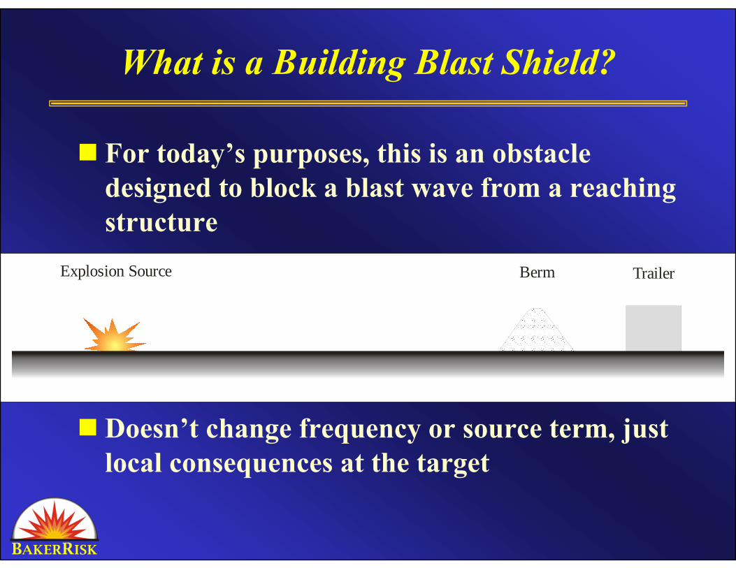
What is a Building Blast Shield?
For today’s purposes, this is an obstacle designed to block a blast wave from a reaching structure
Doesn’t change frequency or source term, just local consequences at the target
Explosion Source Berm Trailer
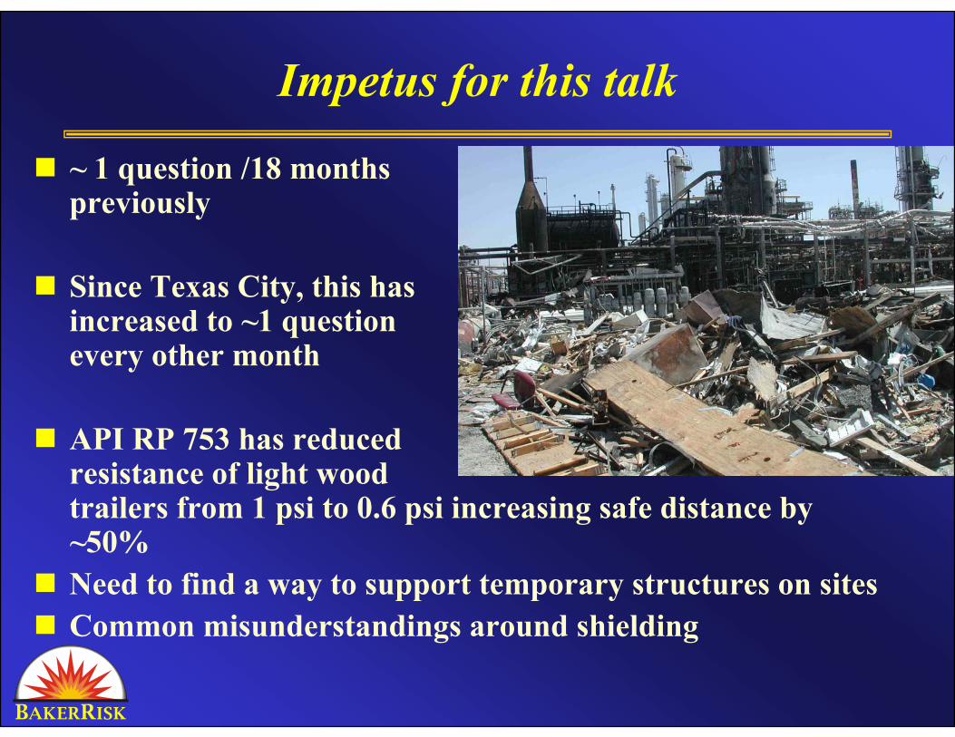
Impetus for this talk
~ 1 question /18 monthspreviously
Since Texas City, this hasincreased to ~1 questionevery other month
API RP 753 has reducedresistance of light wood trailers from 1 psi to 0.6 psi increasing safe distance by ~50%Need to find a way to support temporary structures on sitesCommon misunderstandings around shielding
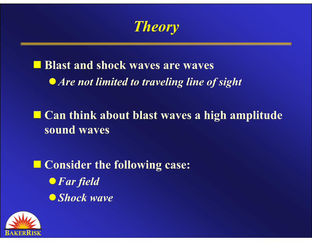
Theory
Blast and shock waves are wavesAre not limited to traveling line of sight
Can think about blast waves a high amplitude sound waves
Consider the following case:Far fieldShock wave
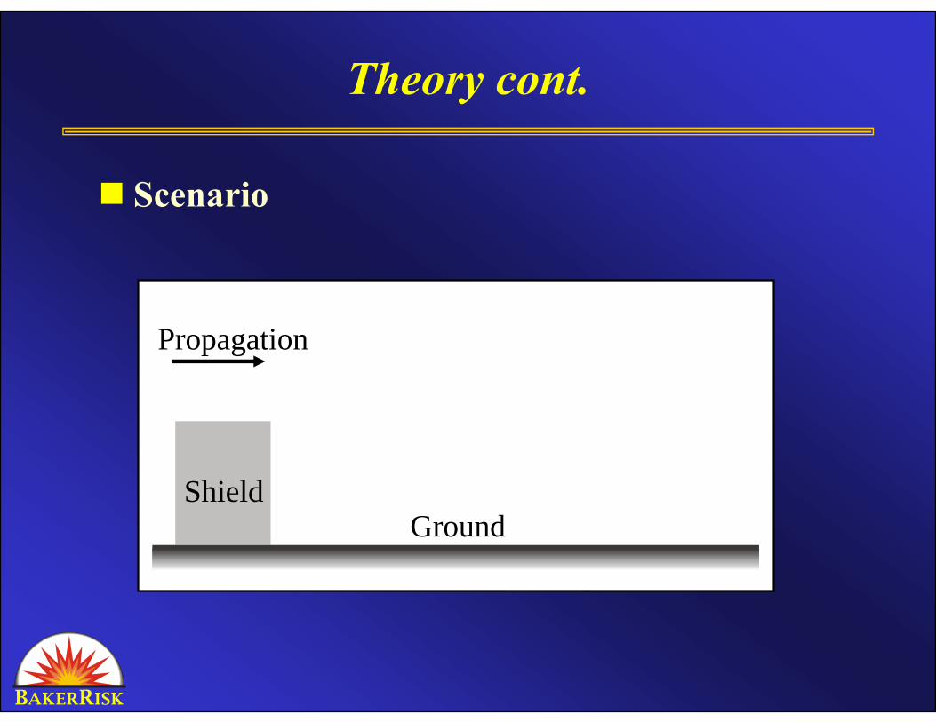
Theory cont.
Scenario
ShieldGround
Propagation
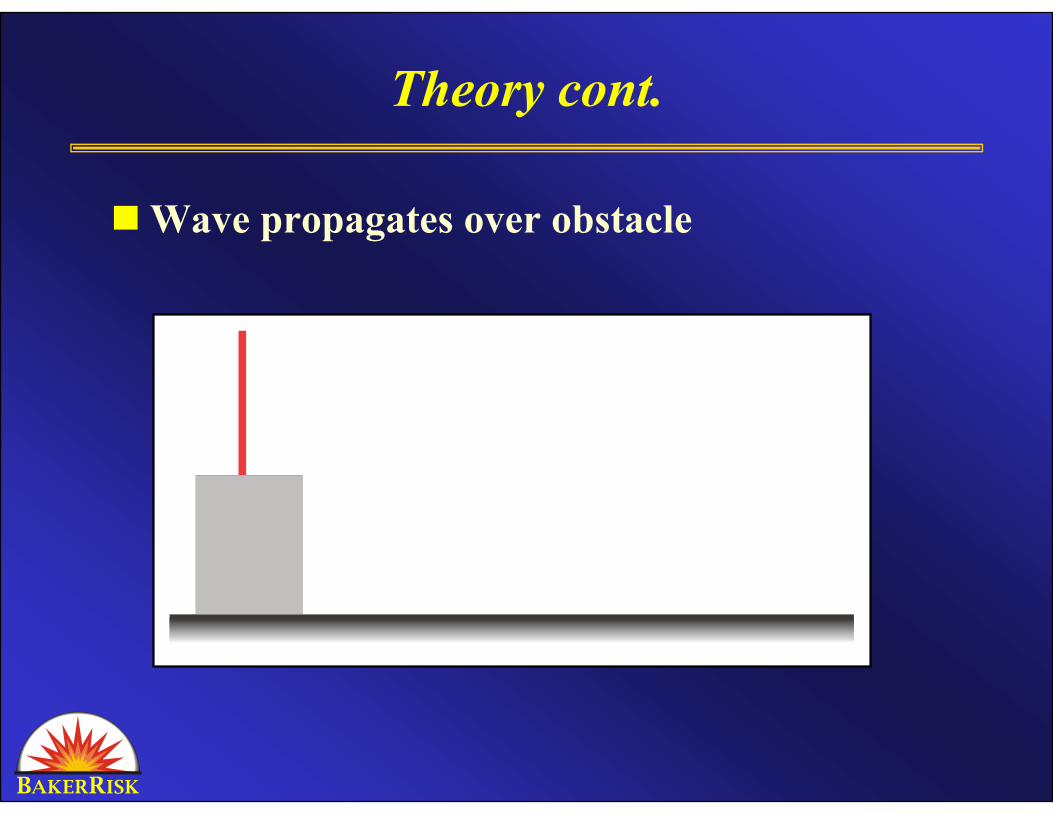
Theory cont.
Wave propagates over obstacle
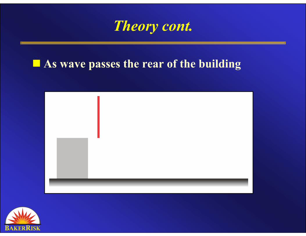
Theory cont.
As wave passes the rear of the building
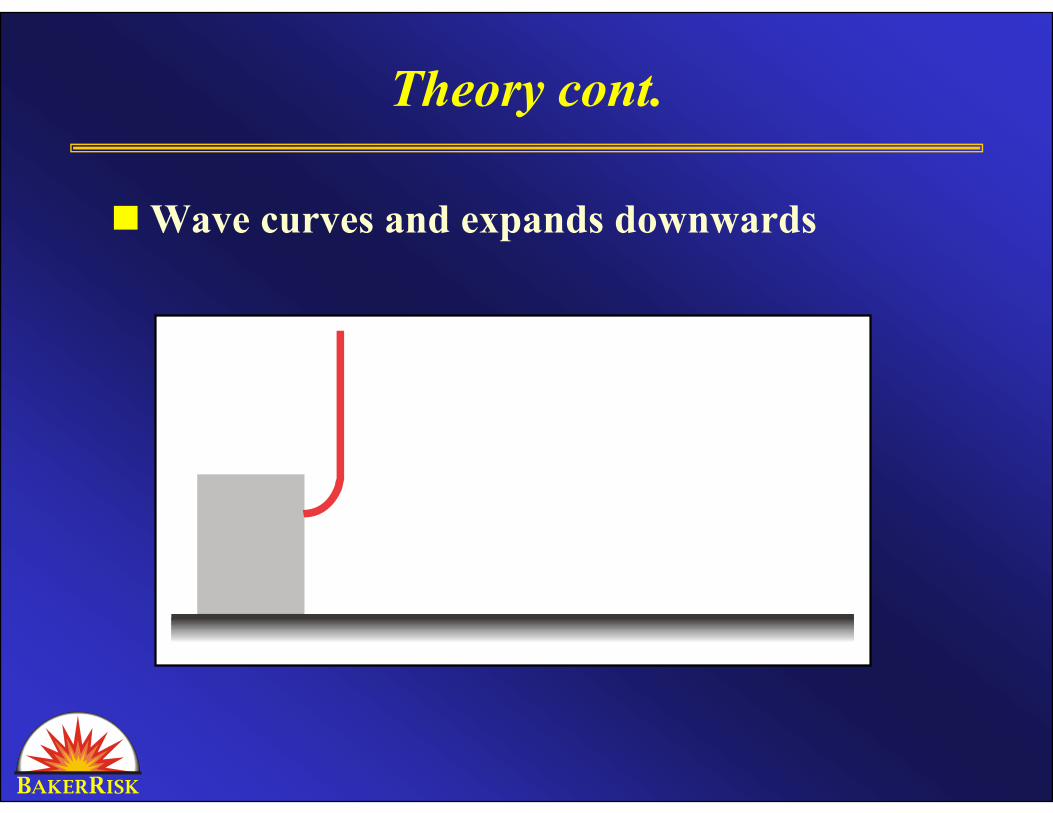
Theory cont.
Wave curves and expands downwards
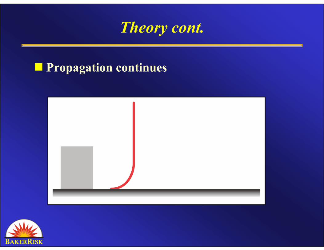
Theory cont.
Propagation continues
Theory Conclusions
Blast wave still loads back face of obstacle
Expansion through rarefaction reduces blast loadLoad immediately behind the shield reduces
Wave re-forms downstreamEssentially unaffected by shield in far field
Direction of loading behind shield is different
Rule of Thumb Disclaimer
It must be noted that this analysis is for general scoping only and should not be used for final
design. If a company wishes to pursue the use of a berm or blast wall for blast protection, a numerical analysis should be performed to
accurately analyze the situation and provide results that can be used for design.
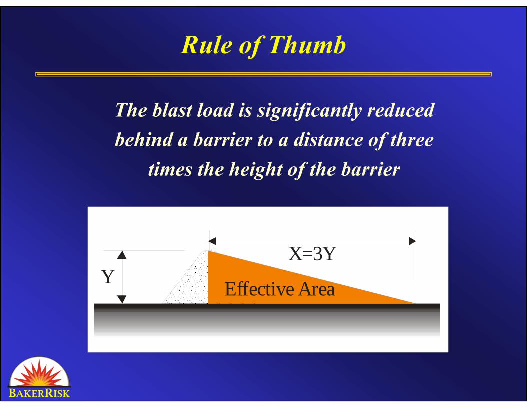
Rule of Thumb
The blast load is significantly reducedbehind a barrier to a distance of three
times the height of the barrier
YX=3Y
Effective Area
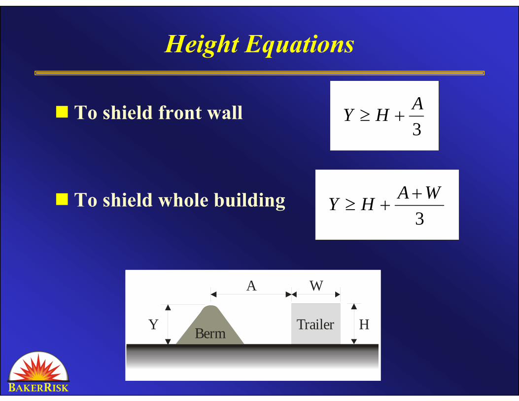
Height Equations
To shield front wall
To shield whole building
BermY H
A W
Trailer
3AHY +≥
3WAHY +
+≥
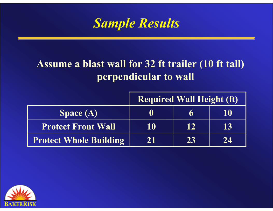
Sample Results
Assume a blast wall for 32 ft trailer (10 ft tall) perpendicular to wall
242321Protect Whole Building131210Protect Front Wall1060Space (A)
Required Wall Height (ft)
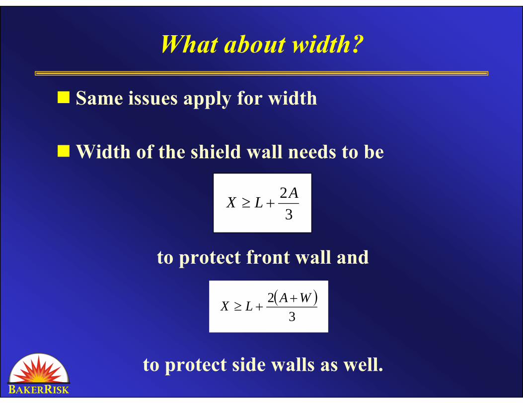
What about width?
Same issues apply for width
Width of the shield wall needs to be
to protect front wall and
to protect side walls as well.
( )3
2 WALX ++≥
3
2ALX +≥
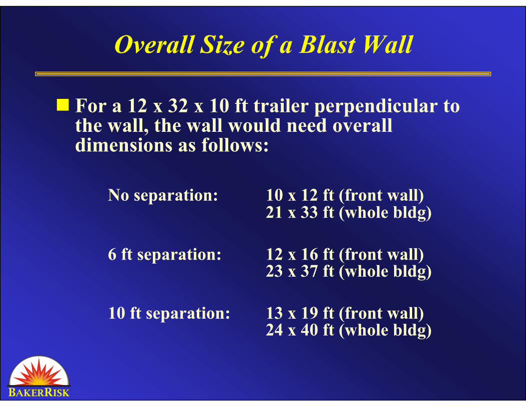
Overall Size of a Blast Wall
For a 12 x 32 x 10 ft trailer perpendicular to the wall, the wall would need overall dimensions as follows:
No separation: 10 x 12 ft (front wall)21 x 33 ft (whole bldg)
6 ft separation: 12 x 16 ft (front wall)23 x 37 ft (whole bldg)
10 ft separation: 13 x 19 ft (front wall)24 x 40 ft (whole bldg)
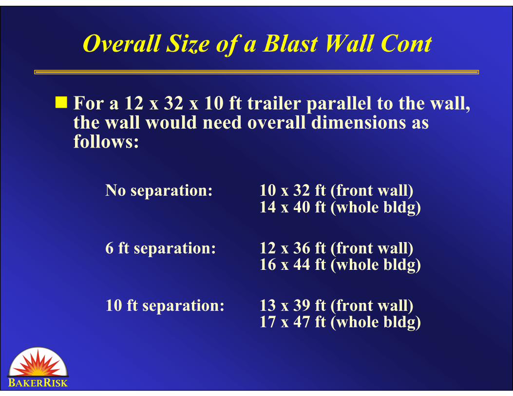
Overall Size of a Blast Wall Cont
For a 12 x 32 x 10 ft trailer parallel to the wall, the wall would need overall dimensions as follows:
No separation: 10 x 32 ft (front wall)14 x 40 ft (whole bldg)
6 ft separation: 12 x 36 ft (front wall)16 x 44 ft (whole bldg)
10 ft separation: 13 x 39 ft (front wall)17 x 47 ft (whole bldg)
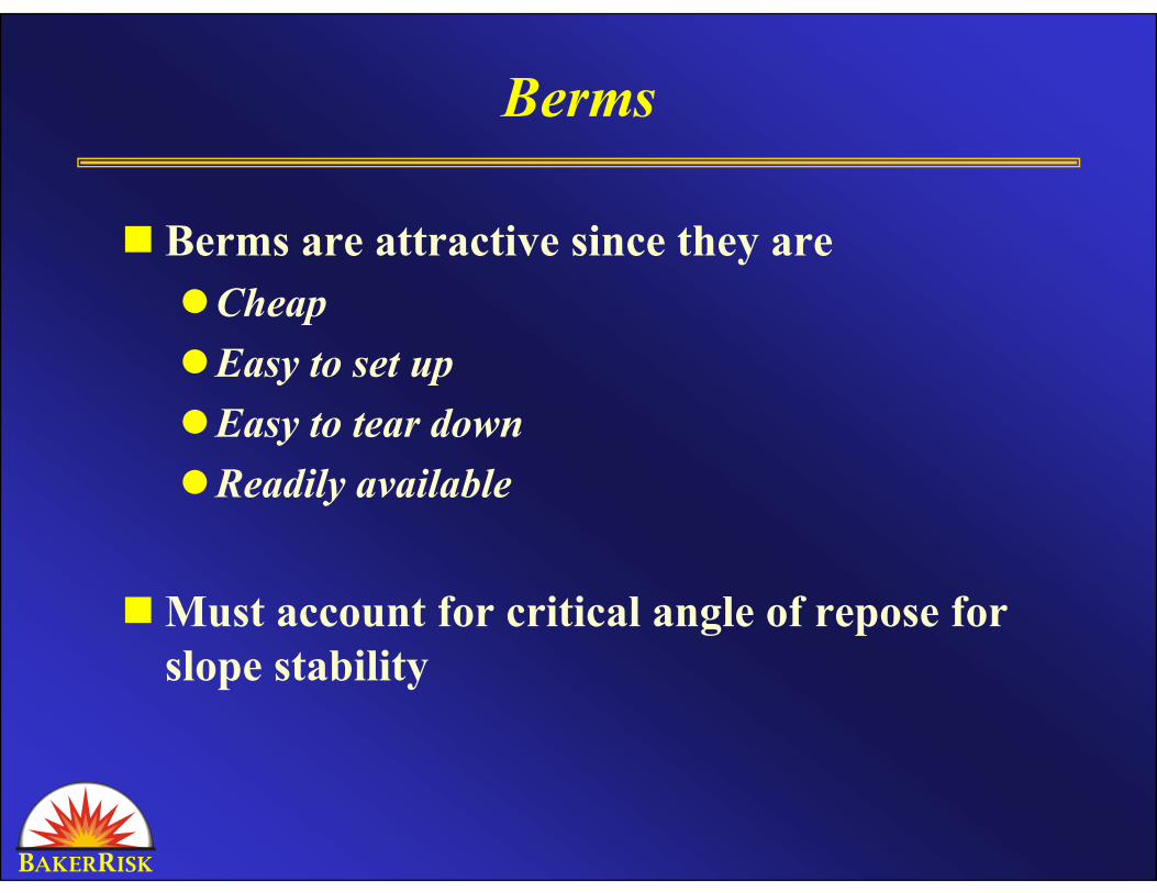
Berms
Berms are attractive since they areCheapEasy to set upEasy to tear downReadily available
Must account for critical angle of repose for slope stability

Berm Angle of Repose
The angle of repose (α) will control the minimum width of the berm itself according to the following equation:
Sample calculation results are shown for clay (angle of repose = 45 degrees) as a berm material. Other berm materials have smaller angles of repose and the corresponding berm heights and widths would be increased from what is shown here.
( )αtanYA ≥
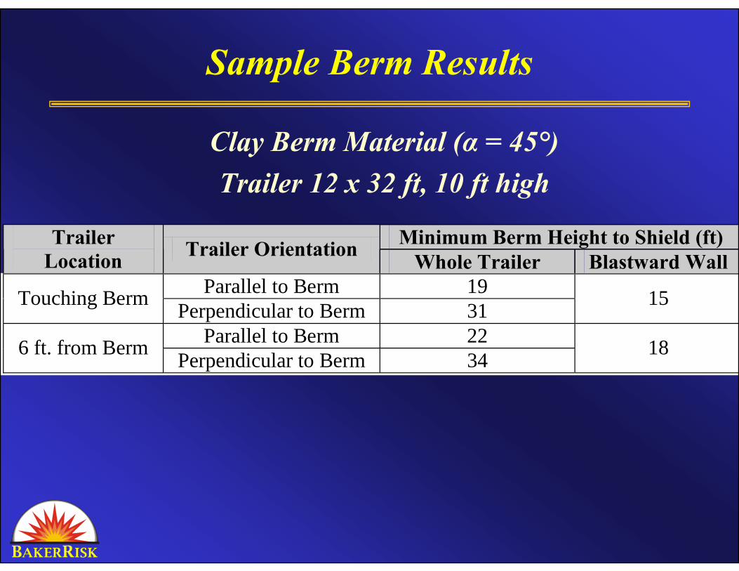
Sample Berm Results
Clay Berm Material (α = 45°)Trailer 12 x 32 ft, 10 ft high
Minimum Berm Height to Shield (ft) Trailer Location Trailer Orientation Whole Trailer Blastward Wall
Parallel to Berm 19 Touching Berm Perpendicular to Berm 31 15
Parallel to Berm 22 6 ft. from Berm Perpendicular to Berm 34 18
“Real Answers”
The Rule of Thumb indicates the area where blast load reduction is “significant”
To quantify reduction, need to run numerical model
Note that blast loading direction may not be the same as when the shield is not there
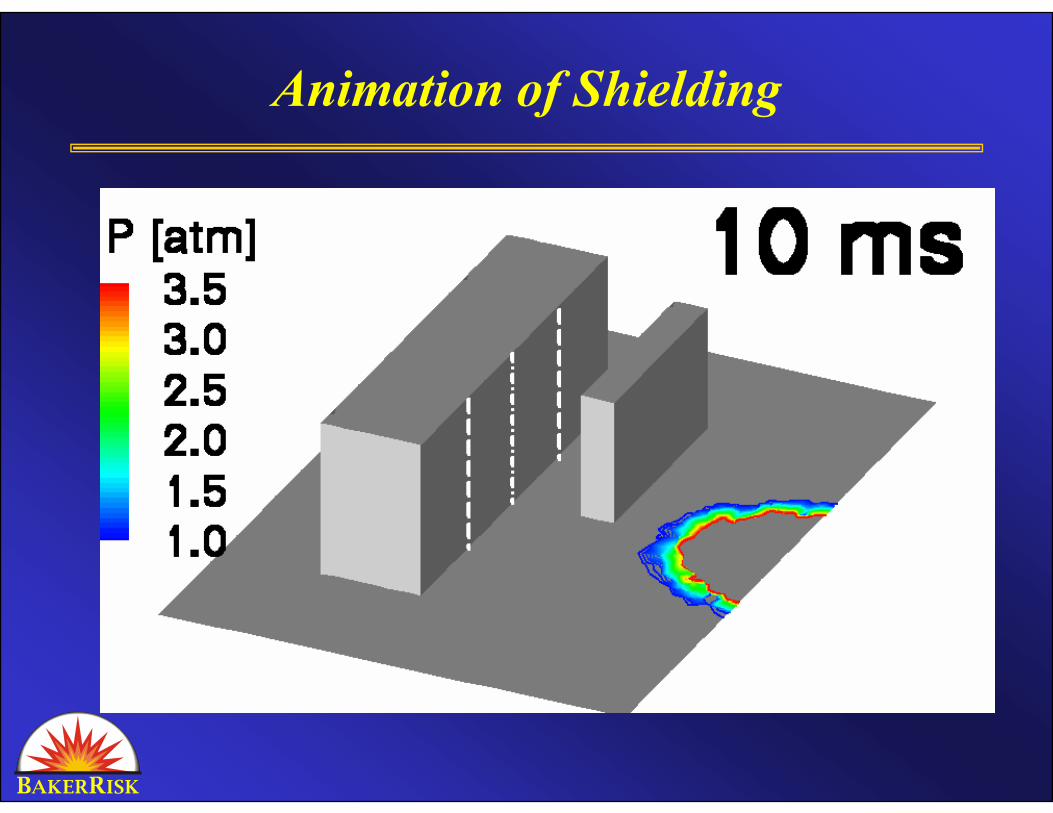
Animation of Shielding
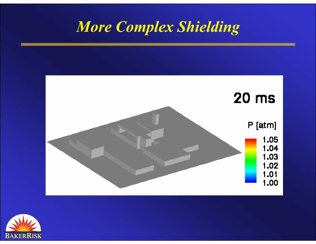
More Complex Shielding
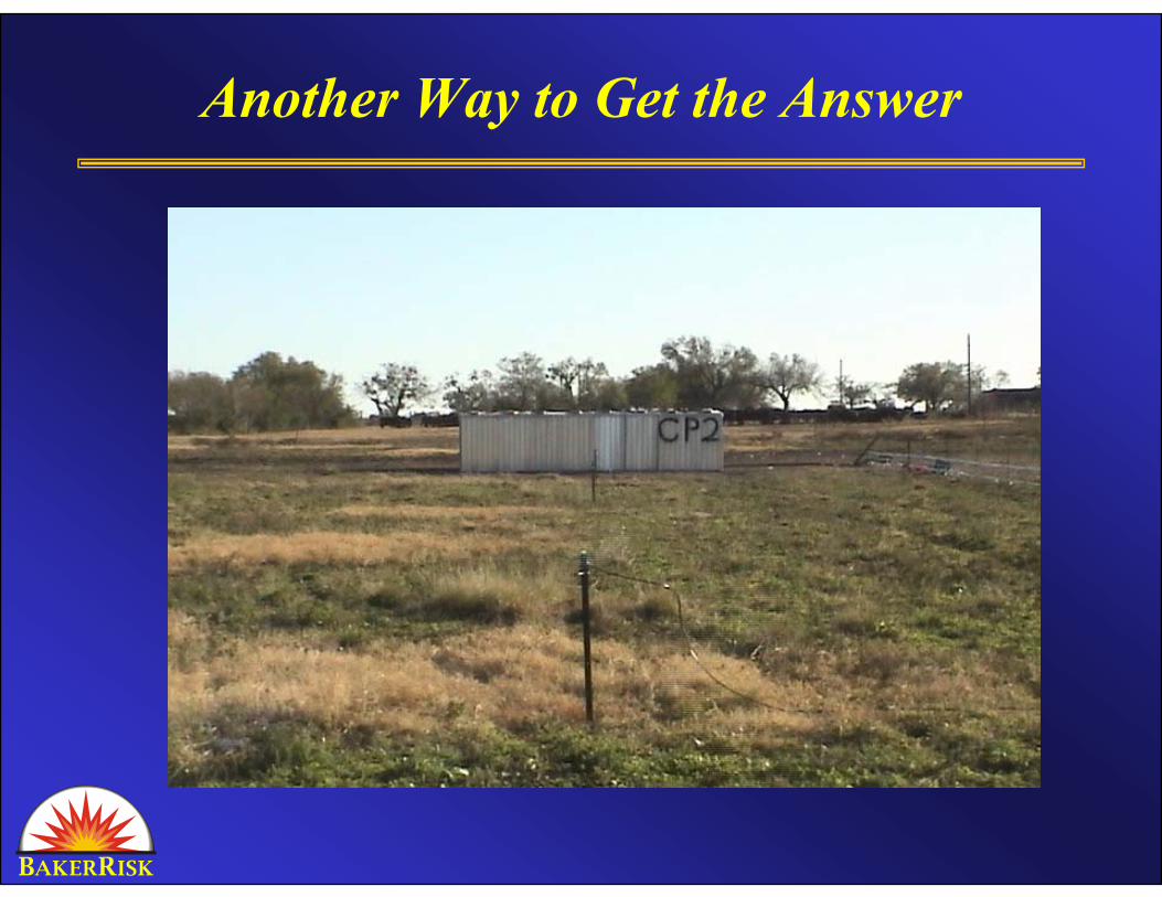
Another Way to Get the Answer
Conclusions
Rule of thumb presented for approximate blast wall sizing
Indicates feasibilityWall needs to resist blast loadMay need significant reaction structure
Numerical analysis needed to determineActual reductionLoad distributionLoad direction

B E R CAKER NGINEERING AND ISK ONSULTANTS
Questions?