building instructions - operating manual€¦ · boc 2 rudder control horn washer plastic pta 1...
TRANSCRIPT

Nuova FULCRO ServiceVia Sesto n.46 - 26100 CREMONA (ITALY)
BUILDING INSTRUCTIONS - OPERATING MANUAL

Xcalibur V.: 2.1 ENG - 14/09/2003
Copyright 2003 Nuova FULCRO ServiceNo parts of this document can be copied neither shared with any media without the author’s per-mission.Nuova FULCRO Service reserves the right to modify this document according to technical im-provement requirements.

INDICE
INDEX
XCALIBUR .........................................................................1Technical data................................................................................................... 1
CHAP. 1 PART LIST, MATERIALS AND TOOLS LIST ...................31.1 Components included in the Xcalibur kit ......................................... 3
1.2 Part needed to complete the kit but not included ............................ 5List of parts you will need to complete the model ............................................. 5Optional parts.................................................................................................... 5
1.3 Tools and materials needed (not included) to complete the kit ...... 6Tools ................................................................................................................. 6Materials............................................................................................................ 6
CHAP. 2 BUILDING INSTRUCTIONS ..............................................72.1 Preliminary operations .................................................................... 7
2.2 Fuselage, elevator and rudder ........................................................ 7Installing the elevators ...................................................................................... 7Elevator bellcrank system installation ............................................................... 10Rudder .............................................................................................................. 12Elevators ........................................................................................................... 15Canopy.............................................................................................................. 16Installing the wing servo connection in the fuselage ......................................... 17Radio equipment baseplate .............................................................................. 18
2.3 Wing ................................................................................................ 21Servo wires ....................................................................................................... 21Installing wing servos ........................................................................................ 23Aileron and flap control ..................................................................................... 23
2.4 Options ........................................................................................... 25Servo actuated tow hook................................................................................... 25Winch hook installation guide - (use a F3B/F3J winch for launching) ............... 26
2.5 Connecting the wing and fuselage .................................................. 27
CHAP. 3 CONTROL TRAVEL VALUES ...........................................29
I

3.1 Control list .......................................................................................29
3.2 Suggested control travel values ......................................................30Ailerons..............................................................................................................30Flaps ..................................................................................................................30Elevator..............................................................................................................30Rudder ...............................................................................................................30
3.3 Centre of gravity ..............................................................................31Checking the position of the CofG.....................................................................31Side balancing ...................................................................................................31
CHAP. 4 DRAWINGS 1:1 SCALE.................................................... 33Servo tray ..........................................................................................................33Fuselage rudder reinforcement..........................................................................34
II

Nuova FULCRO Service
XCALIBURHigh performance glider
Technical dataThe Xcalibur is a general purpose glider designed to offer the best performance in almost all fly-ing conditions, but it isn’t a competition machine. All moulded fiberglass carbon reinforced wingwith carbon spar, thinned RG15 (7.8%), to offer high performance and a very broad flying speedrange; fiberglass carbon reinforced fuselage suited for slope soaring and towing and adaptableto electric flight (there is plenty of room for motor and up to 20 cells), all moving tailplane to im-prove control at all flying speeds.ATTENTION! This model is definitely not suitable for beginners.
Controls: ailerons, flaps, elevator, rudder, (tow release and motor).
Pic.1: Xcalibur.
Wing span: 3170 mm
Wing area: about 56 sq. dm
Length: 1510 mm
Weight: empty about g 2200, flying weight from g 3300
Profile: RG 15 mod. (7.8%)
Radio control: 6 to 8 channels
1

X-MODELS - Xcalibur
2

Nuova FULCRO Service
CHAP. 1 PART LIST, MATERIALS AND TOOLS LIST
1.1 Components included in the Xcalibur kitTable 1: supplied items (fuselage/tail)
COD. QT. Item Remarks
FUS 1 fuselage fiberglass carbon reinforced
CAP 1 canopy fiberglass
CDX 1 right elevator balsa fiberglass sandwich with carbon spar
CSX 1 left elevator balsa fiberglass sandwich with carbon spar
DER 1 rudder fiberglass
ARC 1 elevator pushrod carbon tube 800 mm - 10 mm x 8 mm
BAC 1 elevator main rod steel 115 mm long - diam. 4 mm
BCC 1 elevator bellcrank brass bushingcenter piece
brass - asymmetrical
BLC 2 elevator bellcrank brass bushingouter pieces
brass
ACC 1 elevator rod steel 110 mm long - diam. 2.5 mm
SQR 1 elevator bellcrank hardened alloy CNC machined
TCA 2 pushrod wood adapter wood 40 mm - diam. 8 mm
AM3 2 metal pushrod steel 200 mm - diam. 3 mm - threaded M3 (one side)
DM3 2 nut M3
FO3 2 clevis M3
MAG 4 canopy holder magnet neodym 8 mm - diam, 6 mm
CAV 1 rudder pull-pull cable steel 0.8 mm - 3.0 mm
NOT 2 rudder control horn plastic, threaded M3.
ATD 1 threaded rod for rudder controlhorn
steel 30 mm - threaded M3
BOC 2 rudder control horn washer plastic
PTA 1 rudder rod steel 350 mm - diam. 2 mm
BPT 2 rudder hinge tube plastic 100 mm long - diam. 3 mm x 2 mm
CER 2 rudder hinge plastic
SSS 2 MPX connector male plastic
CUN 4 servo cable electric wire, 4 m, triple, 0.35 square mm section
STB 4 stopper tube brass 10 mm length - diam. 3 mm
3
X-MODELS - Xcalibur
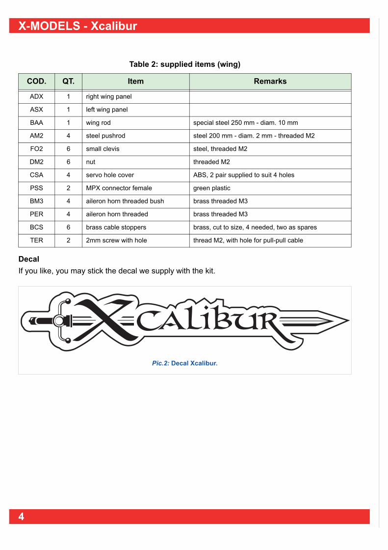
DecalIf you like, you may stick the decal we supply with the kit.
Table 2: supplied items (wing)
COD. QT. Item Remarks
ADX 1 right wing panel
ASX 1 left wing panel
BAA 1 wing rod special steel 250 mm - diam. 10 mm
AM2 4 steel pushrod steel 200 mm - diam. 2 mm - threaded M2
FO2 6 small clevis steel, threaded M2
DM2 6 nut threaded M2
CSA 4 servo hole cover ABS, 2 pair supplied to suit 4 holes
PSS 2 MPX connector female green plastic
BM3 4 aileron horn threaded bush brass threaded M3
PER 4 aileron horn threaded brass threaded M3
BCS 6 brass cable stoppers brass, cut to size, 4 needed, two as spares
TER 2 2mm screw with hole thread M2, with hole for pull-pull cable
Pic.2: Decal Xcalibur.
4

Nuova FULCRO Service
1.2 Part needed to complete the kit but not includedThese are the part you will need to complete the model (see “List of parts you will need to com-plete the model”) and some you may need as option (see “Optional parts”).
List of parts you will need to complete the modelTo complete the model you will need the following:
Note: not included in the table are glues and small parts that should obviously be present in every modeler’s house.
Optional partsIf you like, you may install a tow release device for air-towing and/or a hook to launch the modelusing a winch or a bungee.
Air-towing:If you want to tow the Xcalibur you will need to install a towing cable release system; many devic-es are available on the market, one of the easier to find that works correctly is the Graupner Best.- Nr. 1065.
You will need:— n.1 servo at least 6 kg (suggested HITEC HS-5645MG);— n.1 kit Graupner Best. - Nr. 1065. Note: feel free to use any tow release device you feel confident too; anyway from experience never use a servo withless than 6 kg of real power.
Winch - bungee:You may install a hook to take advantage of a winch or a bungee assisted launch; you will need:— hard wood piece (or better plywood) 150 x 20 x 5 mm.— tow hook, heavy duty F3B like.Note: there is room enough inside the fuselage to install both the hook and the tow release device.
Table 3: Part needed to complete the model (NOT INCLUDED)
COD. QT. Item Remarks
SEA 4 wing servos suggested HITEC HS125MG or HS5125MG
SED 1 rudder servo suggested HITEC HS-525BB
SEP 1 elevator servo suggested HITEC HS-925MG or HS 5925MG
CSS 4 extension servo cable with plug 1 m - connectors to suit your radio equipment (you mayavoid to use these)
RIC 1 receiver with xtal at least 6 channel
BAT 1 rx battery 4 ~ 5 elements, at least 1700 mA
IOO 1 rx switch
5

X-MODELS - Xcalibur
1.3 Tools and materials needed (not included) to complete the kit
ToolsThis tools may help you while assembling the kit:— electric drill;— cutter;— solder;— hair drier;— sand paper 400 and 180 grit;— set of files;— usual tools like screwdrivers, pliers, etc.;— Z-Bend pliers;— rubber bands;— some cleaning paper.Note: other tools may help you too...
Materials— super-glue (CA, cyano, like Green ZAP)— 5 minute epoxy;— tape;— double adhesive tape, thin;— about 200 grams lead;— velcro, 20 cm.Pay attention to the safety instructions for the use of any kind of glue or tools.
If you should need we may supply all you need to complete your Xcalibur
Nuova Fulcro Service S.r.l. - Via Sesto, 46 - 26100 CREMONA (ITALY).Tel. 0039 0372 35138 Fax 0039 0372 27121 e-mail: [email protected]
6

Nuova FULCRO Service
CHAP. 2 BUILDING INSTRUCTIONSThese are our suggestion to achieve an accurate completion of our kit.
2.1 Preliminary operationsKit components controlHave a look at the components (see “PART LIST, MATERIALS AND TOOLS LIST” at page 3) soyou may easily identify these. It is strongly suggested to trial fit all the parts “dry” before gluingthe same.
2.2 Fuselage, elevator and rudder
Installing the elevators This is the hardest part in building this model, please pay attention.
Elevator rod• Try to insert the elevator rod “BAC” into the bras asymmetrical bush “BCC”: it should go with-
out being too “hard” to insert (in case you may use some 400 grit sand paper).
Elevator bellcrank brass bushing outer pieces• Try to “dry” fit the bush, and if too tight, you
will have to clean the hole using a sharp cut-ter (see picture 4) until they fit correctly.
Pic.4: Cleaning the bush holes.
Pic.3: Elevator rod inserted in the asymmetrical bush.
7

X-MODELS - Xcalibur
Tailplane-fuselage alignement controlYou will have to check for the correct aligne-ment of the elevator rod “BAC” respect to thefuselage and to the wing. Follow this procedure:• insert WHITOUT GLUE the bush “BLC” in
the left hole (see picture 5);
Pic.5: Insert left bush.
• from the other side insert (see picture 6), theelevator main rod “BAC” complete with thebrass bushing central piece “BCC”;
• then insert TEMPORARILY the other brassouter bushing “BLC”;
Pic.6: Insert the main elevator rod.
• Insert the wing rod “BAA” in its fuselage hole(see picture 7).
Now it is time to check for the right elevatoralignement:• looking from behind, check for the correct
alignement between the two rods (wing andelevator (see picture 8).
Pic.7: Wing rod inserted in its hole.
If the two rod are not parallel (see picture 8),you will need adjust the rear mounting (see“Adjustments” at page 9).
Pic.8: Misaligned rods.
wing rod
elevator rod
8

Nuova FULCRO Service
AdjustmentsIn this case you must (using a sharp knife or around file) cut away some material from thebottom part of the hole (higher than normalside) and from the top of the hole, lower thannormal side (see picture 9).Go carefully and check the alignment frequent-ly (see picture 8) until both rods are parallel.
Pic.9: Slightly enlarging the hole.
Once satisfied:• remove the rod and the bushes “BAC”+“BCC”+“BLC” from the fuselage;• mix some 5 minute epoxy and put some around one of the bushing “BLC”;• insert the bush in the left hole (see picture 5);• wipe away any excess of glue using cleaning tissue;• from the opposite side insert the elevator rod complete with the central bush, and then the out-
er bushing (DO NOT GLUE THIS SECOND BUSH YET);• using a rubber band keep the rod “BAC” at
the correct alignement until the epoxy dries(see picture 10);
• once the epoxy has dried take away theright bush and the rod.
Pic.10: Correction of vertical mis-alignement.
9

X-MODELS - Xcalibur
Elevator bellcrank system installationLet’s divide it in 3 part to make description easier: rear part; front part; pushrod.
Rear part• Drill a 3 mm hole in the wooden adaptor “TCA”.Please refer to picture 11:• glue (using CA or epoxy) inside one of the
“TCA” the 3 MA threaded rod “AM3” (gluethe non threaded end);
• insert the nut “DM3” to mid thread “DM3”andthe clevis “FO3”;
• connect the clevis to the bellcrank “SQR”.
Front partPlease refer to picture 11:• glue (using CA or epoxy) inside one of the
“TCA” the 3 MA threaded rod “AM3” (gluethe non threaded end);
• insert the nut “DM3” to mid thread “DM3”andthe clevis “FO3”.
Pushrod • Check for the length of the carbon pushrod “ARC” (depending on the place you will install the
elevator servo it should be between around 750 mm);• insert and glue the rear part (see picture 13);Note: do not glue the front part yet, as the finallength of the pushrod will depend from the exactplace you will install the elevator servo (see “Radioequipment baseplate” at page18).
Pic.13: Glueing the rear part.
Installing the elevator bellcrankOnce installed and glued the second outerbushing the bellcrank assembly will be impos-sible to be removed, so please pay attention.Please refer to picture 14:• Insert the carbon pushrod from behind, until
the hole (1) from the elevator bellcrank“SQR” will be in line with the hole (2);
• insert the elevator rod with the central bush-ing “BAC”+“BCC”; please note that the long-est side of the BCC is on the side indicatedby the arrow (3);
Pic.14: How to insert the elevator rod.
Pic.11: Elevator pushrod (rear - not in scale).
TCA AM3 DM3 FO3
SQR
Pic.12: Elevator pushrod (front - not in scale).
TCAAM3DM3FO3
1 23
10

Nuova FULCRO Service
• insert the elevator rod “ACC” (see picture15), through the rear hole in the elevatorbellcrank “SQR” do not use glue;
• move the carbon pushrod “ARC” back andforth from the fuselage front opening tocheck for free movement of the rod “ACC”; ifneeded gently enlarge (using a sharp knifeor a file) the opening pointed by the arrow(see picture 15).
Pic.15: Insert the elevator rod.
Longitudinal alignement control• Insert the two elevator halves “CDX” e
“CSX” on the rods “BAC” and “ACC” andcheck for the alignement.
Alignement correction (if needed)Should the elevator not be correctly aligned, asin picture 16, you will need to correct it:• slightly enlarge the right hole for the “BLC”
until the rod “BAC” is perfectly aligned.
Pic.16: Elevator alignement check.
Final installation of the right bushingOnce satisfied with the alignement:• insert the rod complete with the centre bush
“BAC”+“BCC”; mix some 5 minute epoxyand spread around the bush “BLC”;
• insert the bush “BLC”, clean any excess ofglue. (see picture 17);
• check for the correct alignment and keep inposition until the epoxy has dried.
Pic.17: Position of the tailplane mounting. 90°
11

X-MODELS - Xcalibur
Rudder
Preliminary works• drill a 3 mm hole were indi-
cated by the arrows in pic-ture 18;
Pic.18: Position of the holes.
• with a sharp knife make cutsin the rudder “DER” for thetwo rudder hinges “CER”,where indicated picture 19;
Pic.19: Where to make the cuts.
• clean the cuts using a flatfile;
• insert the two pieces of tube“BPT” into the two cuts andglue with CA;
Pic.20: Rudder hinge workings.
• insert the rudder rod “PTA” inside “BPT” and till the other hole;• insert a hinge “CER” in each
cut;• do not glue the rod “PTA”;
just keep it in place with apiece of clear tape.
Note: keeping the rod in place withtape will allow you to remove the rud-der easily for maintenance work in fu-ture!
4 mm
149 mm90 mm 65 mm
4 mm
BPT BPTCER CERPTA
Pic.21: Assembled group.
12
Nuova FULCRO Service
Rear fuselage reinforcement for the rudder hingesPleas refer to the 1:1 scale drawings (see “Fuselage rudder reinforcement wood.” at page 34),and make the wooden part.
Installing the hinges• Dry fit the hinges to the
wood reinforcement (seepicture 22).
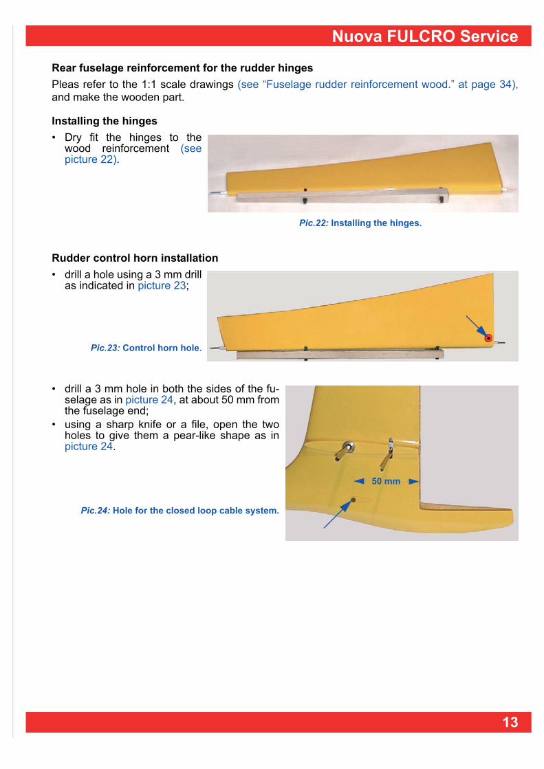
Rudder control horn installation• drill a hole using a 3 mm drill
as indicated in picture 23;
Pic.23: Control horn hole.
• drill a 3 mm hole in both the sides of the fu-selage as in picture 24, at about 50 mm fromthe fuselage end;
• using a sharp knife or a file, open the twoholes to give them a pear-like shape as inpicture 24.
Pic.24: Hole for the closed loop cable system.
Pic.22: Installing the hinges.
50 mm
13

X-MODELS - Xcalibur
Installing the rudder• Dry fit the rudder and the wood reinforcement in
place;• check for free movement (You may need to move
the hinges in or out to achieve a good fit with cor-rect movement).
When satisfied:• mix some 5 minute epoxy, spread it on the sides
of the wood reinforcement and glue it in position;keep it in place with your hands or clamps untilthe epoxy has dried (see picture 25);
Pic.25: Installing the rudder.
Rudder control The rudder control horn consists of the threaded rod“ATD”, two plastic washers and two plastic horns“NOT”; the rudder control is actuated through aclosed loop cable.• Screw one of the two plastic horn on the threaded
rod (see picture 26);
• insert the threaded rod in the rudder hole with awasher and horn installed;
• insert from the other side the other washer andthe horn.
Pic.27: Rudder in place.
Pic.26: Rudder control horns and threaded rod.
14

Nuova FULCRO Service
ElevatorsUsing pliers, slightly bend each end of the“ACC” rod (see picture 28), so it will fit tightlyinside the tube: this will keep the elevators inplace during flight but still able you to easilychange the rod if you bend it; during a badlanding or after an accident;
Pic.28: Gently bending the elevator rod.
• the rod must go inside its tube with some re-sistance but without having to push toomuch (see picture 29);
Pic.29: Inserting the rod in its tube.
• try fitting the elevator halves (see picture30);
Should the two elevators go together too easilythey may come loose during flight; in this casebend the “ACC”. rod a little more.
Pic.30: Installing the elevators.
15
X-MODELS - Xcalibur
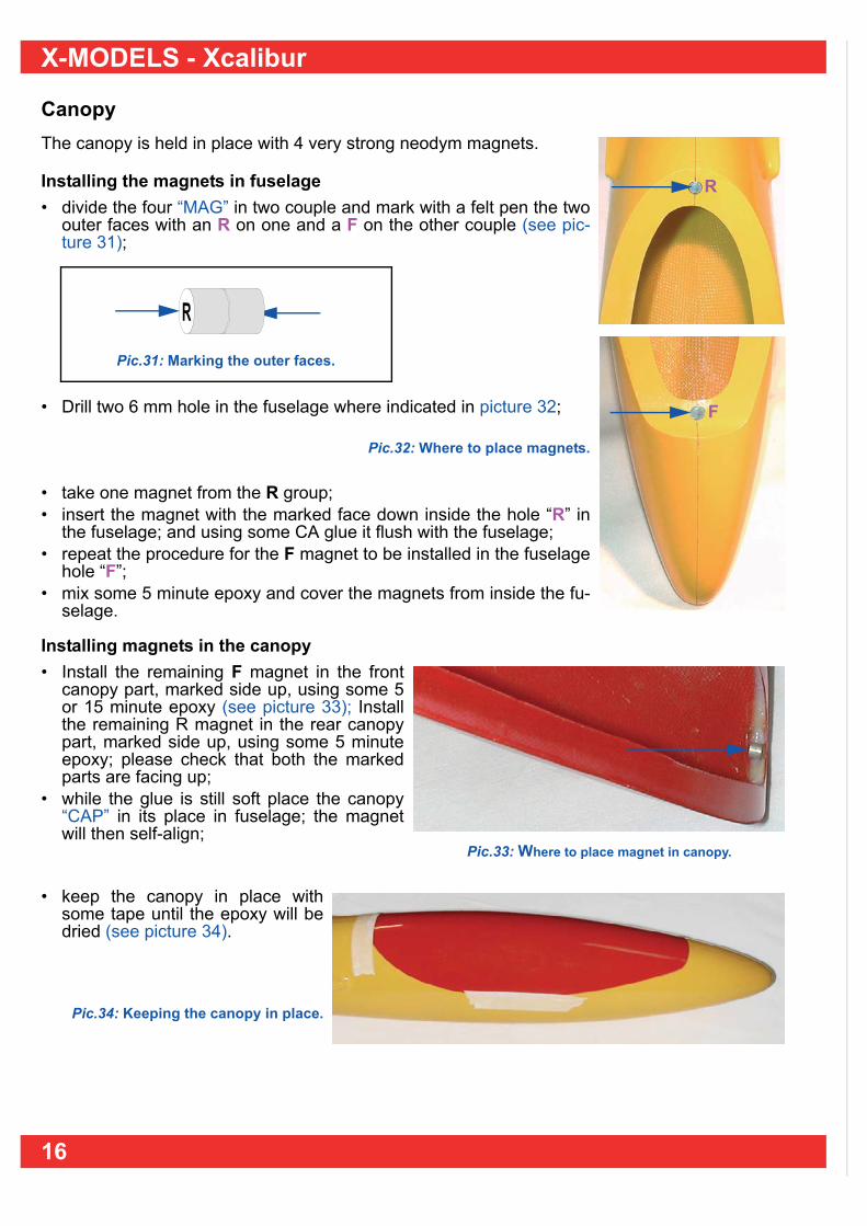
CanopyThe canopy is held in place with 4 very strong neodym magnets.
Installing the magnets in fuselage• divide the four “MAG” in two couple and mark with a felt pen the two
outer faces with an R on one and a F on the other couple (see pic-ture 31);
• Drill two 6 mm hole in the fuselage where indicated in picture 32;
Pic.32: Where to place magnets.
• take one magnet from the R group;• insert the magnet with the marked face down inside the hole “R” in
the fuselage; and using some CA glue it flush with the fuselage;• repeat the procedure for the F magnet to be installed in the fuselage
hole “F”;• mix some 5 minute epoxy and cover the magnets from inside the fu-
selage.
Installing magnets in the canopy • Install the remaining F magnet in the front
canopy part, marked side up, using some 5or 15 minute epoxy (see picture 33); Installthe remaining R magnet in the rear canopypart, marked side up, using some 5 minuteepoxy; please check that both the markedparts are facing up;
• while the glue is still soft place the canopy“CAP” in its place in fuselage; the magnetwill then self-align;
• keep the canopy in place withsome tape until the epoxy will bedried (see picture 34).
Pic.34: Keeping the canopy in place.
R
F
Pic.31: Marking the outer faces.
R
Pic.33: Where to place magnet in canopy.
16

Nuova FULCRO Service
Installing the wing servo connection in the fuselageYou will logically need to disconnect the wingservos from the receiver during transportationof the model; we suggest the use of a MPXmulti connector for this purpose, but pleaseconsider this just one suggestion and feel freeto finish the model the way you like in this re-spect.
Enlarging the hole in fuselage• With a flat file (see picture 35), enlarge tho
hole to the size of 18 x 8 mm.Pic.35: Enlarging hole.
Connection drawings • You will need 4 servo plugs with wire “CUN” to suit your radio equipment (if you are cutting the
plugs from the wing servos, you can use those). Please check that the wires will be longenough to reach your receiver and protrude about 5 cm from the fuselage;
• insert every single wire in a 10 mm piece of heatshrink tube and then solder the wires to the“SSS” connectors, following the drawings as for picture 36.
• with a hot air gun shrink the heatshrinksleeves;
• insert the ready made wire system in the fu-selage hole (see picture 37).
Pic.37: Fuselage with servo wires.
Pic.36: How to solder the servo wires.
+
_~~
+
_~~
17

X-MODELS - Xcalibur
Radio equipment baseplateATTENTION! If you intend to install a winch hook, (see “Winch hook installation guide - (use a F3B/F3Jwinch for launching)” at page26) now is the time to install the hook.
Note: we give here some ideas on how to install the radio equipment; please note that these are just suggestions.• from a piece of 5 mm birchwood ply cut the servo tray as shown in the template in picture 71 at
page 33;• temporarily insert the servos;• mark with a pencil the place to drill the holes for the servo’s screws, then remove servos;• drill the holes using a 1.8 mm drill;• install the servo tray in the fuselage and glue it with 5 minute epoxy (see picture 38);
Note: you will have to rotate the servo tray to install it.• instal the elevator servo “SEP” and the rudder servo “SED”;• heck that the two servo horns will not come in contact (see picture 39).
Elevator control, final task• Insert the front part (see “Front part” at
page10) inside the carbon pushrod (see“Pushrod” at page10);
• connect the clevis to the elevator servo horn(see picture 40);
Pic.40: Connect the elevator pushrod.
Pic.38: Dry fitting the servo tray.
Pic.39: Installing servos.
18

Nuova FULCRO Service
• lock temporarily the elevator at 0° (flush withthe moulding on fuselage;
• take out the front part of the elevator push-rod, spread some 5 minute epoxy on thewooden piece and re-install it; connect theclevis to servo and wait for the epoxy to dry(see picture 41).
Rudder closed loop controlPlease note that the closed loop system works much better if you connect the wires “crossed”see picture 44 at page 20).You will need cutting nippers for squeezing the stopper tubes “STB” (you may use the cutting ar-ea of standard pliers).• Insert the cable through the stopper tube, then through the rudder horn and again through the
stopper tube;• squeeze with the cutting nippers in two dif-
ferent places (see picture 42).Note: You need not worry about cutting the cables: a lotof strength is required to cut the steel wires.
The finished work should look like in picture 42 (rightside).
Pic.42: Squeeze the tube in two different places.
• Cut the closed loop cable “CAV” into two equal pieces;• insert the rudder control cables through the holes in the
fuselage;• prepare the control linkage by screwing a nut “DM2”
about half way on the screw with the hole “TER” andthen screwing on the clevis “FO2” until it is against thescrew (see picture 43);
• working with a cable on the inside of the fuselage, inserts one cable end through a stoppertube “STB”, the hole in the screw and again through the stopper tube;
• lock the cable by squeezing the stopper tube with cutting nippers;• do the same for the other cable;• connect the clevises to the outer hole in the rudder servo horn keeping the cable crossed;• temporary plug the radio set to the rudder servo in order to adjust its central position;• turn the radio on and center the rudder servo;• take one cable that is coming up the fuselage and insert it through a stopper tube, through the
hole in the rudder horn “NOT” and again through the stopper tube (DO NOT SQUEEZE YET!);• do the same for the other side;• tension the cables so that the rudder is in the neutral position, move the stopper tubes close to
the rudder horn and squeeze the tubes with cutting nippers to lock them in place;Note: minor adjustments in the tensioning can be made at the servo end by loosening or tightening the clevises.
Pic.41: Installing the front part.
Pic.43: clevis, nut and screw assembly.
DM2FO2
TER
19
X-MODELS - Xcalibur
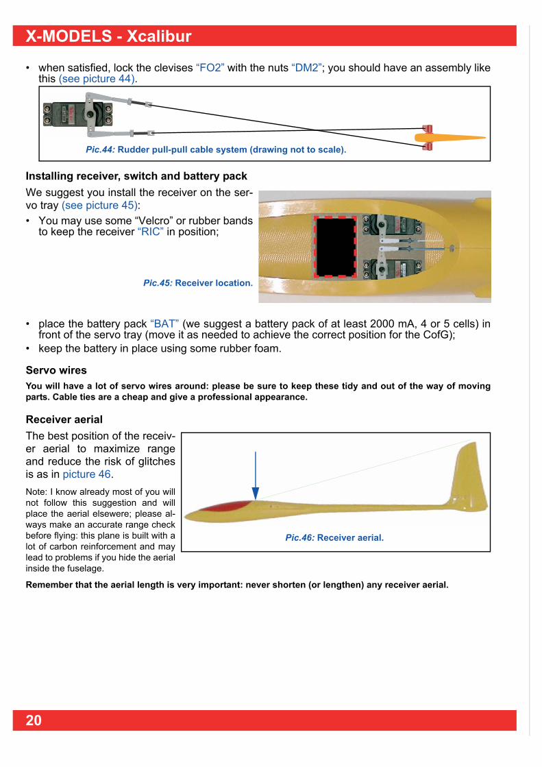
• when satisfied, lock the clevises “FO2” with the nuts “DM2”; you should have an assembly likethis (see picture 44).
Installing receiver, switch and battery packWe suggest you install the receiver on the ser-vo tray (see picture 45):• You may use some “Velcro” or rubber bands
to keep the receiver “RIC” in position;
Pic.45: Receiver location.
• place the battery pack “BAT” (we suggest a battery pack of at least 2000 mA, 4 or 5 cells) infront of the servo tray (move it as needed to achieve the correct position for the CofG);
• keep the battery in place using some rubber foam.
Servo wiresYou will have a lot of servo wires around: please be sure to keep these tidy and out of the way of movingparts. Cable ties are a cheap and give a professional appearance.
Receiver aerial The best position of the receiv-er aerial to maximize rangeand reduce the risk of glitchesis as in picture 46.Note: I know already most of you willnot follow this suggestion and willplace the aerial elsewere; please al-ways make an accurate range checkbefore flying: this plane is built with alot of carbon reinforcement and maylead to problems if you hide the aerialinside the fuselage.
Remember that the aerial length is very important: never shorten (or lengthen) any receiver aerial.
Pic.44: Rudder pull-pull cable system (drawing not to scale).
Pic.46: Receiver aerial.
20

Nuova FULCRO Service
2.3 Wing The wing is in two pieces (a must for transport) and has big aileron and flaps. There are readymade holes for the aileron and flap servos (see picture 47) with enough room to use mini or mi-cro size servos.
Due to the very thin wing section, the servo thickness must be no more than 13 mm. Also, due tothe aileron (and flap) size and to the high speed this plane may reach, you will need to install ser-vos with at least 2.5 kg of power. There are a lot of different servo that will do the job, but have alook at the new HITEC 125 (or better still the digital version, 5125) that are perfect for the job.The procedure is the same for the two wing panels.
Servo wiresYou will have to do some soldering work, so here is a brief note on the servo wires.These days all servos have 3 wires, with the exception of some (now quite old) Sanwa products. Usually there is a black (may be brown) wire that is the negative (-), a redthat is the positive (+) and a yellow (or white or orange) that is the signal(~) wire (see picture 48).
Pic.48: Signal (~), positive (+) and negative (-).
You may choose to cut off the servo connectors and solder the servos direct to the wiring loom,alternatively you may leave the connectors and use additional extension leads with female con-nectors ready installed. There are advantages and disadvantages with either.
a) leave the servo plugs attachedThis choice will leave the servo “as it was made” and allow for easier servo substitution (if need-ed); but you will have two more connectors in every servo line that may oxidize, and is heavier.• Remember to insert each wire in a 10 mm long piece of heatshrink tube before soldering it;• check that the cable will be long enough to reach each servo; solder the servo female cable
“CSS” to the Multiplex multi connector “PSS” as in picture 49;
Pic.47: The servo holes.
+_~
Pic.49: Servo connections drawing.
+
_~~
21

X-MODELS - Xcalibur
• cover every solder joint with the heatshrink tube and shrink it;• using a file enlarge the hole for the multi connector in the wing rib; • insert the wire assembly and glue the mpx connector as shown in picture 50;
• connect the two servo female connector “CSS” to the servos “SEA”.
b) servos soldered directIn this case you will make the things easier, safer and lighter but you have to overcome your fear(!) of cutting the servo original wire; the picture 51 shows the drawings.
Note: the positive and negative wire of the two servo may be connected to one wire only (each) saving in weight; thesignals must have their own wire.• You will need about 3 metres of servo wire, suggested section is at least 0,35 square millime-
ters;• split it in two 1 m long sections and two 50 cm long sections;• remember to slide a 10 mm length of heatshrink tube over each wire before soldering;• solder the wire to the multi connector as for the scheme in picture 51; (the 50 cm will reach the
flap servo and the 100 cm long the aileron servo;• place the heatshrink sleeve over the soldered joint and shrink it;• using a file enlarge the hole for the multi connector in the wing rib; • insert the wire assembly and glue the mpx connector as shown in picture 50.Flap servo connection: • cut the servo wire at about the half of the original length;• remember to insert the wire to be soldered into the heatshrink
sleeve;• solder the wire (see picture 52) and shrink the sleeve;
Pic.52: Flap servo wire schematic.
Pic.50: Position of mpx connector.
Pic.51: Schematic drawings for direct servo connections.
+
_~~
22
Nuova FULCRO Service
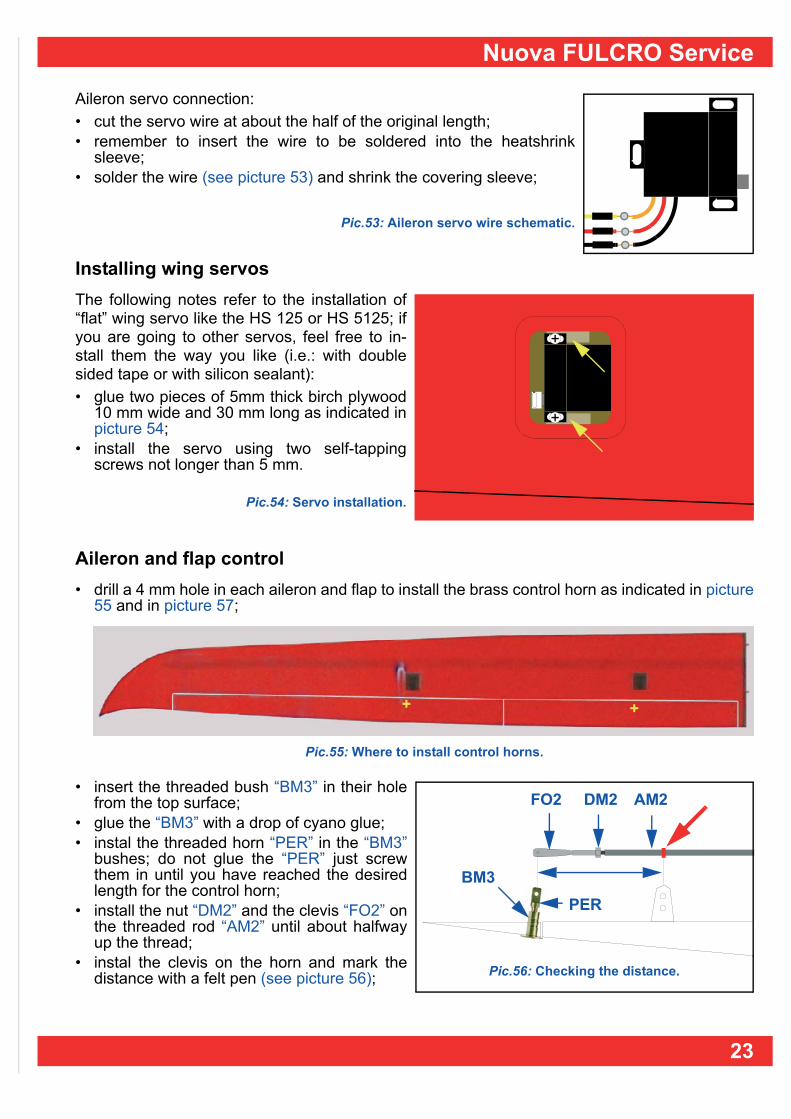
Aileron servo connection:• cut the servo wire at about the half of the original length;• remember to insert the wire to be soldered into the heatshrink
sleeve;• solder the wire (see picture 53) and shrink the covering sleeve;
Pic.53: Aileron servo wire schematic.
Installing wing servosThe following notes refer to the installation of“flat” wing servo like the HS 125 or HS 5125; ifyou are going to other servos, feel free to in-stall them the way you like (i.e.: with doublesided tape or with silicon sealant):• glue two pieces of 5mm thick birch plywood
10 mm wide and 30 mm long as indicated inpicture 54;
• install the servo using two self-tappingscrews not longer than 5 mm.
Pic.54: Servo installation.
Aileron and flap control• drill a 4 mm hole in each aileron and flap to install the brass control horn as indicated in picture
55 and in picture 57;
• insert the threaded bush “BM3” in their holefrom the top surface;
• glue the “BM3” with a drop of cyano glue;• instal the threaded horn “PER” in the “BM3”
bushes; do not glue the “PER” just screwthem in until you have reached the desiredlength for the control horn;
• install the nut “DM2” and the clevis “FO2” onthe threaded rod “AM2” until about halfwayup the thread;
• instal the clevis on the horn and mark thedistance with a felt pen (see picture 56);
Pic.55: Where to install control horns.
++
DM2FO2 AM2
BM3PER
Pic.56: Checking the distance.
23

X-MODELS - Xcalibur
• make a “Z” bend using the “Z plier”: themark made with the felt pen must be whereindicated by the yellow arrow (see picture57);
• insert the “z” in the servo horn and connectthe clevis to the control horn;
Pic.57: Making the “z” bend.
Servo coversYou have to cut out the twoservo covers from the supplied“CSA” piece (see picture 58);• cut along the lines as in pic-
ture 58.
Pic.58: Cutting the servo covers.
• using sand paper fit the cover perfectly onthe recess in the wing (see picture 59);
Note: if you wish you may paint the cover to match thebottom wing color.• using clear tape keep the servo cover in po-
sition.
Pic.59: Cover in place.
24
Nuova FULCRO Service
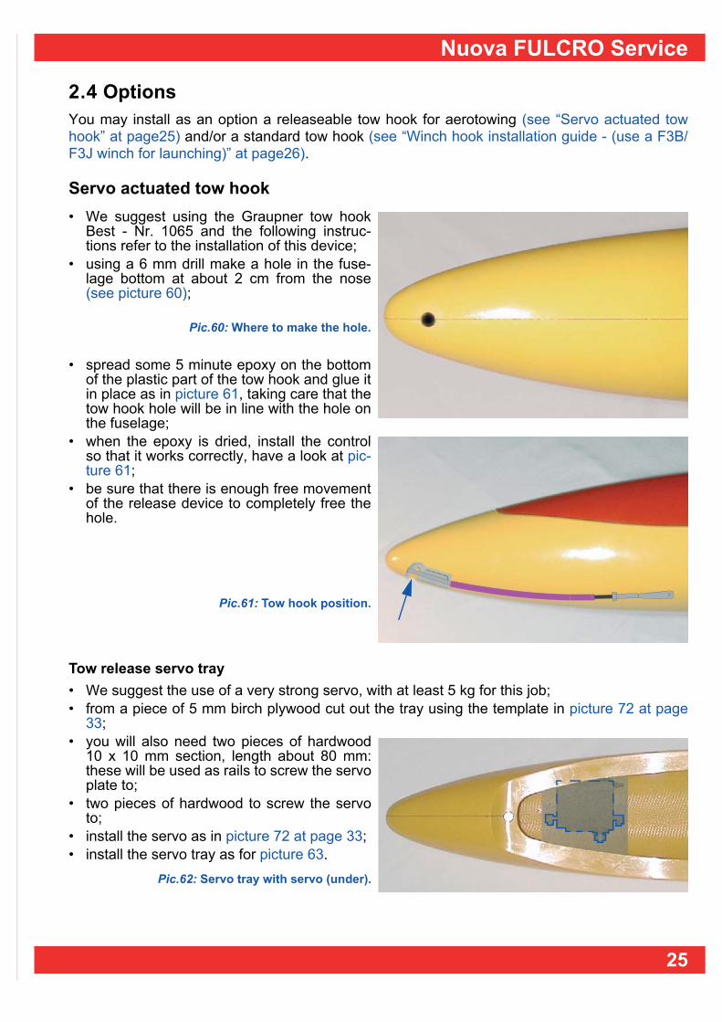
2.4 Options You may install as an option a releaseable tow hook for aerotowing (see “Servo actuated towhook” at page25) and/or a standard tow hook (see “Winch hook installation guide - (use a F3B/F3J winch for launching)” at page26).
Servo actuated tow hook • We suggest using the Graupner tow hook
Best - Nr. 1065 and the following instruc-tions refer to the installation of this device;
• using a 6 mm drill make a hole in the fuse-lage bottom at about 2 cm from the nose(see picture 60);
Pic.60: Where to make the hole.
• spread some 5 minute epoxy on the bottomof the plastic part of the tow hook and glue itin place as in picture 61, taking care that thetow hook hole will be in line with the hole onthe fuselage;
• when the epoxy is dried, install the controlso that it works correctly, have a look at pic-ture 61;
• be sure that there is enough free movementof the release device to completely free thehole.
Pic.61: Tow hook position.
Tow release servo tray• We suggest the use of a very strong servo, with at least 5 kg for this job;• from a piece of 5 mm birch plywood cut out the tray using the template in picture 72 at page
33;• you will also need two pieces of hardwood
10 x 10 mm section, length about 80 mm:these will be used as rails to screw the servoplate to;
• two pieces of hardwood to screw the servoto;
• install the servo as in picture 72 at page 33;• install the servo tray as for picture 63.
Pic.62: Servo tray with servo (under).
25

X-MODELS - Xcalibur
Winch hook installation guide - (use a F3B/F3J winch for launching)If you wish to install a hook, first bond a piece of hard wood, of about 150 x 10 x 10 mm, as a re-inforcement inside the fuselage.• Glue the wood reinforce-
ment (150 x 10 x 10 mm)in the fuselage, using 5minute epoxy, as indicat-ed in picture 64.
The position of the tow hook must be about 10 mm in front of the CofG (see “Centre of gravity” atpage31). Make several holes if you wish to have adjustable tow positions relative to the CofG.
Pic.63: Connect the clevis to the servo horn.
Pic.64: Where to place the wood reinforcement.
26

Nuova FULCRO Service
2.5 Connecting the wing and fuselage• First insert the wing rod in the fuselage;• slide a wing panel part way onto the rod and
connect the mpx connector (see picture 65);Note: be careful when connecting the mpx connectors.
Pic.65: Connecting the MPX connector.
• slide wing on fully (see picture 66), payingattention that the wire goes freely inside thefuselage.
Pic.66: Connection of the wing to the fuselage.
Repeat for the opposite wing:• slide the panel part way onto the rod and
connect the mpx connector (see picture 67).
Pic.67: Attaching the other wing panel.
• now slide panel on fully, again paying attention to the wires.
27

X-MODELS - Xcalibur
28

Nuova FULCRO Service
CHAP. 3 CONTROL TRAVEL VALUES
3.1 Control listPlease refer to the picture 68:— aileron 1 and 2;— flap 3 and 4;— elevators 5 and 6;— rudder 7.
1
3
5
Pic.68: Controls list.
7
2
4
6
29
X-MODELS - Xcalibur
3.2 Suggested control travel valuesThe travel values indicated are just suggestions; please feel free to modify them to suit your fly-ing needs; all the values are in mm and are measured at the outer part unless specified.
AileronsThe ailerons are mainly used during turns, but with this model you may also use them as flaper-ons to change the profile camber and as air-brakes during landings.Up ....................... 10 mm (low rate) / 14 mm (high rate) / 2 mm (flaperons) / 20 mm (butterfly);Down ................... 8 mm (low rate) / 10 mm (high rate) / 2 mm (flaperons).
FlapsMainly used to change the camber of the profile, you may use them as ailerons to improve theroll rate and as air-brake for landing (butterfly)Up ....................... 3 mm (flap - profile) / 6 mm (aileron);Down ................... 4 mm (flap - profile) / 3 mm (aileron) / 30 mm (butterfly).
Elevator Please note that the elevator neutral is with the elevator flush with the fairings on the fuselage.Up ....................... 8 mm (low rate) / 10 mm (high rate);Down ................... 8 mm (low rate) / 10 mm (high rate).Note: travel value at the elevator root chord, next to the fuselage
RudderRight ........................ as much as you can;Left .......................... as much as you can.
Exponential and dual ratesThe suggested travel values for dual rates are indicated as low rates - high rates.The use of exponential control is a personal preference, which appeals to some flyers and othersavoid.
30

Nuova FULCRO Service
3.3 Centre of gravityWe suggest startingwith a CofG position70 ~ 75 mm from thewing leading edge atthe root (see picture69). After the first flights youmay wish to change theCofG position to better suityour flight needs.
Pic.69: Centre of gravity location.
Checking the position of the CofGTo check the CofG:• mark on the bottom of the wing the CofG position and balance the model on your index fingers
(from bottom): it should stay level;• If not add required lead ballast;• remember that the model must be completed with all parts (battery, receiver, etc.) when
checking the CofG.
Side balancingIn large gliders it is important to check for side balancing, i.e. to check if there is a difference inweight between one wing panel and the other; it will not take long and you will be rewarded withbetter flight performance.
How to check • Lay the assembled model on a flat and even surface;• keep level;• the heaviest wing (if any) will fall and touch the ground (see picture 70);
• repeat the test several times to ensure that you know which wing is heavier;• add a few grams of lead in the servo hole in the lighter wing;• repeat until you obtain a good balance.
70 ~ 75 mm
Pic.70: You will have to add weight to the lighter wing, the one that always stays up.
31

X-MODELS - Xcalibur
32

Nuova FULCRO Service
CHAP. 4 DRAWINGS 1:1 SCALEWe suggest you make a copy of the drawings, taking care to keep them full size.
Servo trayUse 5 mm birchwood ply.There is ample space (see picture 71)for:— receiver (1);— elevator servo (2);— rudder servo (3);— receiver switch (4). Note: the servo size is just an indication;please make the holes to suit your equipment.
Pic.71: servo tray.
Tow release servo tray (optional)The optional tow release servo tray(see picture 72) is only needed if youwant to install a tow release servo;here is the template to cut the servotray from a piece of 5 mm birch ply-wood
Pic.72: Tow release servo tray.
2
4
3
1
100
mm
88 mm
86 mm
64 mm
82 mm
82 m
m
33

X-MODELS - Xcalibur
Fuselage rudder reinforcementThe internal rudder reinforcement (see picture72) may be made from 5 mm plywood or from8 mm hard balsa • the design is full size • the holes are meant for the supplied hinges:
if you use a different system you will notneed them.
Pic.73: Fuselage rudder reinforcement wood.
240
mm
6 mm
4 mm
149
mm
78 m
m
6 mm
4 mm
5 m
m
5 mm
12 mm
34