building lego robots for first lego leagueen1000/07s1/lego_building_tutorial.pdf · building lego...
TRANSCRIPT

Building LEGO RobotsFor
FIRST LEGO League
Version: 1.0Sept. 23, 2002
ByDean Hystad
www.hightechkids.org

About the Author and This Document
Dean Hystad is a first class LEGO fanatic. Dean is an engineer for MTS Systems locatedin Eden Prairie, Minnesota. MTS Systems Corporation is one of the worldís leadingsuppliers of mechanical testing and simulation equipment, making everything fromearthquake simulators to amusement park rides. At MTS, Dean writes control softwarefor a range of large robotic systems. As you can see in this book, Dean brings thatexpertise to his passion for LEGO. Dean has judged at FLL events for several years andis currently working as a contributing author on a soon-to-be published book on LEGOMindstorms. Dean can be reached at [email protected].
This book is a significant piece of work, and frankly is awe inspiring to me. It is anexcellent mix of theory and practice. Some of the text may be beyond middle schoolyouth, but the accompanying labs and presentation material should help coachesunderstand the concepts and present key ideas to their teams. The book can also provide auseful text for those of you wanting to incorporate FLL into high school classes. I hopeyou find it useful.
This book fits well with INSciTE's mission to advance innovative programs that providean environment where kids, educators, and the technical community come together tocultivate life long learning in science, math and technology.
Fred [email protected] PresidentSeptember 20, 2002
Copyright and Trademark Notice
© 2002 INSciTE in agreement with, and permission from FIRST and the LEGO Group. This document isdeveloped by INSciTE and is not an official FLL document from FIRST and the LEGO Group. This
document may be freely copied and distributed, electronically or otherwise, in its entirety only, and only ifused in conjunction with FIRST LEGOÆ League. Any use, reproduction, or duplication of this manual
for purposes other than directly related toFIRST LEGO League is strictly prohibited without specific written permission from INSciTE.
LEGO , ROBOLAB, and MINDSTORMS are trademarks of the LEGO Group used here withspecial permission. FIRST LEGO League is a trademark owned by FIRST (ForInspiration and Recognition of Science and Technology) and the LEGO Group
used here with special permission. INSciTE is a trademark of Innovations in Science and TechnologyEducation.
INSciTEPO Box 41221
Plymouth, MN 55441
www.hightechkids.org

Table of Contents
1 Structures ................................................................................................................1-11.1 Bricks, Plates, and Beams ...............................................................................1-11.1.1 Bricks ......................................................................................................1-11.1.2 Plates.......................................................................................................1-21.1.3 Beams .....................................................................................................1-31.1.4 Axles and Pins.........................................................................................1-31.1.5 LEGO Vocabulary ..................................................................................1-4
1.2 Building a Frame ............................................................................................1-51.2.1 LEGO Geometry.....................................................................................1-7
1.3 SNOT..............................................................................................................1-92 Gears.....................................................................................................................2-122.1 Spur Gears ....................................................................................................2-122.1.1 Gear Spacing.........................................................................................2-122.1.2 Gear Ratio .............................................................................................2-162.1.3 Torque...................................................................................................2-182.1.4 Speed.....................................................................................................2-202.1.5 Gear Trains............................................................................................2-212.1.6 Clutch Gear ...........................................................................................2-23
2.2 Crown Gear...................................................................................................2-242.3 Bevel Gear ....................................................................................................2-242.4 Worm Gear ...................................................................................................2-252.4.1 Directional Transmission ......................................................................2-27
2.5 Differential....................................................................................................2-272.5.1 Ratchet Splitter......................................................................................2-29
2.6 Gear Rack .....................................................................................................2-302.7 Pulleys...........................................................................................................2-312.7.1 Torque...................................................................................................2-32
2.8 Reinforcing gear trains..................................................................................2-332.9 Backlash........................................................................................................2-34
3 Wheels ..................................................................................................................3-373.1 Sizes..............................................................................................................3-373.1.1 Speed.....................................................................................................3-373.1.2 Force .....................................................................................................3-39
3.2 Treads ...........................................................................................................3-413.3 Balance .........................................................................................................3-423.3.1 Finding the Center Of Gravity...............................................................3-423.3.2 Inertia ....................................................................................................3-43
3.4 Wheel Loading and Friction..........................................................................3-464 Lego Electronics ...................................................................................................4-484.1 RCX Brick ....................................................................................................4-484.1.1 Firmware...............................................................................................4-484.1.2 Programming ........................................................................................4-49
4.2 Motors...........................................................................................................4-51

4.2.1 Modes....................................................................................................4-524.2.2 Attaching...............................................................................................4-53
4.3 Touch Sensor ................................................................................................4-544.3.1 Bumpers................................................................................................4-554.3.2 Limit and Position Switches..................................................................4-574.3.3 Rotation sensor......................................................................................4-57
4.4 Light Sensor..................................................................................................4-584.4.1 Experiment #1, Color ............................................................................4-594.4.2 Experiment #2, Ambient Light..............................................................4-64
4.5 Rotation Sensor.............................................................................................4-664.5.1 Resolution .............................................................................................4-664.5.2 Internals ................................................................................................4-674.5.3 Counting Errors.....................................................................................4-68
4.6 Sensor Stacking.............................................................................................4-695 Robot Drives .........................................................................................................5-705.1 Differential Drive..........................................................................................5-705.1.1 Casters...................................................................................................5-715.1.2 Wheel Configuration.............................................................................5-735.1.3 Steering .................................................................................................5-745.1.4 Steering Made Easier ............................................................................5-765.1.5 Straight Line Travel ..............................................................................5-765.1.6 Differential Skid....................................................................................5-78
5.2 Steering drive................................................................................................5-795.2.1 Turning..................................................................................................5-805.2.2 Tricycle Drive .......................................................................................5-82

FiguresFigure 1-1. Basic LEGO Brick ......................................................................................1-1Figure 1-2. Brick Dimensions........................................................................................1-1Figure 1-3. Three Plates = One Brick high ....................................................................1-2Figure 1-4. Simple Gearbox Using Technic Plates ........................................................1-2Figure 1-5. Technic Beams ............................................................................................1-3Figure 1-6. Pins and Axles.............................................................................................1-3Figure 1-7. Studs on the Side of a Beam?......................................................................1-4Figure 1-8. A Typical Driven Wheel Assembly.............................................................1-4Figure 1-9. A 16L Technic Pin ......................................................................................1-4Figure 1-10. Common Technic Pieces ...........................................................................1-5Figure 1-11. Simple Frame ............................................................................................1-5Figure 1-12. Improved Frame ........................................................................................1-6Figure 1-13. Cross Braced Frame ..................................................................................1-6Figure 1-14. Snap On Connections are Weak in Tension ..............................................1-7Figure 1-15. Cross Bracing ............................................................................................1-7Figure 1-16. Two Cross Bracing Choices ......................................................................1-8Figure 1-17. A Tall Frame .............................................................................................1-8Figure 1-18. Diagonal Cross Bracing.............................................................................1-9Figure 1-19. One of Jennifer Clark's Incredible Creations. Yes itís LEGO. ...............1-10Figure 1-20. Turning 90 degrees. Studs Out ...............................................................1-10Figure 1-21. Turning 90 degrees. Studs In..................................................................1-11Figure 1-22. Upside Down...........................................................................................1-11Figure 1-23. Extending Beams Using Pins and Plates .................................................1-11Figure 2-1 Lego Spur Gears.........................................................................................2-12Figure 2-2. Stud Gear Spacing.....................................................................................2-13Figure 2-3. Half Stud Spacing Using 2 Holed 1 x 2 Beam ..........................................2-14Figure 2-4. Vertical Gear Spacing ...............................................................................2-14Figure 2-5. Circumventing Vertical Gear Spacing Restrictions...................................2-15Figure 2-6. Diagonal Gear Spacing..............................................................................2-15Figure 2-7. Circumventing Diagonal Gear Spacing Restrictions ..................................2-16Figure 2-8. 3:1 Gear Ratio ...........................................................................................2-17Figure 2-9. Torque = Force x Distance ........................................................................2-18Figure 2-10. The Ratio of the Torques is Equal to the Ratio of the Radii ....................2-19Figure 2-11. Ratio of Angular Velocities is Equal to Inverse Ratio of the Radii .........2-20Figure 2-12. Multi-stage Gear Train ............................................................................2-21Figure 2-13. Idler Gear ................................................................................................2-23Figure 2-14. Using Clutch Gear to Limit Forces..........................................................2-23Figure 2-15. Crown Gear .............................................................................................2-24Figure 2-16. Bevel Gear...............................................................................................2-24Figure 2-17. A Small Wheel Built from Two 12t Bevel Gears ....................................2-25Figure 2-18. Worm Gear..............................................................................................2-25Figure 2-19. Using the Worm Gear's Self Locking Feature.........................................2-26Figure 2-20. LEGO Lead Screw ..................................................................................2-26Figure 2-21. Directional Transmission.........................................................................2-27Figure 2-22. LEGO Differential...................................................................................2-27

Figure 2-23. During Turns the Wheels Cover Different Distances ..............................2-28Figure 2-24. Using Differential to Calculate Average Rotation...................................2-29Figure 2-25. Using a Differential to Calculate Difference in Rotation ........................2-29Figure 2-26. Ratchet Splitter .........................................................................................2-30Figure 2-27. LEGO Gear Rack and Pinion ..................................................................2-30Figure 2-28. Pulleys and Belts .....................................................................................2-31Figure 2-29. Lego Pulleys............................................................................................2-31Figure 2-30. Two ways to Increase Torque Capacity...................................................2-32Figure 2-31. Using Pulleys to Limit Torque ................................................................2-33Figure 2-32. Forces on gears........................................................................................2-33Figure 2-33. Gearboxes Donít Have to be Big to be Strong ........................................2-34Figure 2-34. Backlash is caused by poor gear meshing ...............................................2-34Figure 2-35. Preloading a gear train with a rubber band..............................................2-35Figure 2-36. Split gear made from LEGO....................................................................2-36Figure 3-1. Lego Wheels and Tires..............................................................................3-37Figure 3-2. A Very Fast Tractor...................................................................................3-39Figure 3-3. Force = Torque / Radius............................................................................3-40Figure 3-4. Tracked Robot...........................................................................................3-41Figure 3-5. Mario Ferrari's Johnny 5............................................................................3-41Figure 3-6. Wheelbase .................................................................................................3-42Figure 3-7. Finding CG Using Balance Method ..........................................................3-43Figure 3-8. Modified Balance Method.........................................................................3-43Figure 3-9. An Incline Moves the Effective CG ..........................................................3-44Figure 3-10. Turning Generates Forces and Moments.................................................3-45Figure 3-11. FIRST Team 254's Robot "Cheesy Poofs" Does a Victory Wheelie .......3-45Figure 3-12. Cantilevered and Fully Supported Wheels ..............................................3-46Figure 3-13. Wheel Loading ........................................................................................3-46Figure 4-1. The RCX Programmable Brick .................................................................4-48Figure 4-2. RCX Code Screenshot...............................................................................4-50Figure 4-3. ROBOLAB Screenshot ..............................................................................4-50Figure 4-4. 9 Volt Geared Motor .................................................................................4-51Figure 4-5. PWM Duty Cycles ....................................................................................4-52Figure 4-6. Using a Pulley to Increase Drag ................................................................4-53Figure 4-7. Using Color Coding to Document Proper Connector Orientation .............4-53Figure 4-8. Strengthening Motor Mounts with Cross Bracing .....................................4-53Figure 4-9. Motor Mount Using Rails..........................................................................4-54Figure 4-10. Wiring the Touch Sensor.........................................................................4-55Figure 4-11. A Simple Bumper....................................................................................4-55Figure 4-12. A Bumper that Uses the Rotation Sensor ................................................4-55Figure 4-13. A Normally Closed Bumper Design........................................................4-56Figure 4-14. Improved Normally Open Bumper..........................................................4-56Figure 4-15. Position and Limit Switches....................................................................4-57Figure 4-16. A Touch Rotation Sensor ........................................................................4-58Figure 4-17. The Light Sensor .....................................................................................4-58Figure 4-18. Light Sensor Color Experiment...............................................................4-60Figure 4-19. Visible Light Spectrum ...........................................................................4-61

Figure 4-20. The Light Sensor Sees Differently than Our Eyes....................................4-61Figure 4-21. Light Colors ............................................................................................4-62Figure 4-22. Color Experiment Sensor Readings.........................................................4-63Figure 4-23. Ambient Light Experiment......................................................................4-64Figure 4-24. Light Sensor Readings for Gray LEGO Brick.........................................4-65Figure 4-25. Rotation Sensor .......................................................................................4-66Figure 4-26. Using Gear Reduction to Increase Resolution.........................................4-67Figure 4-27. Rotation Sensor Internals. DON'T DO THIS!!! .....................................4-67Figure 4-28. Homemade Rotation Sensor Made From LEGO Parts .............................4-68Figure 4-29. A Homing Switch to Reset the Rotation Sensor......................................4-68Figure 5-1. A Differential Drive Robot........................................................................5-71Figure 5-2. Swivel Casters ...........................................................................................5-71Figure 5-3. Swivel Casters are Self Aligning...............................................................5-72Figure 5-4. Casters Generate Steering Forces While Aligning ....................................5-72Figure 5-5. Diamond Shaped Wheel Layout................................................................5-73Figure 5-6. Triangle Shaped Wheel Layout .................................................................5-74Figure 5-7. Turning Radius is Determined Wheelbase and Relative Speed.................5-74Figure 5-8. Pivoting About a Wheel ............................................................................5-76Figure 5-9. Simple LEGO Slip Limiter........................................................................5-77Figure 5-10. A Locking Differential ............................................................................5-78Figure 5-11. A Pair of Differential Skid Robots ..........................................................5-79Figure 5-12. Two steered wheel robots........................................................................5-80Figure 5-13. Path Planning is Harder for Non-Holonomic Robots ..............................5-80Figure 5-14. Ackerman Steering Minimizes Geometry Induced Wheel Skid ..............5-81Figure 5-15. Turning Radius is Determined by Wheel Base and Steering Angle ........5-81Figure 5-16. Tricycle Drive (Left) and Steering Drive (Right) Robots Look Similar ..5-82Figure 5-17. Any Steer Angle is Possible with a Tricycle Drive .................................5-83

TablesTable 1-1. Calculating Diagonal Lengths ......................................................................1-9Table 2-1. Spur Gear Sizes ..........................................................................................2-13Table 2-2. Diagonal Gear Spacing ...............................................................................2-16Table 2-3. Gear Ratios for LEGO Spur Gears .............................................................2-18Table 2-4. Measured pulley diameters .........................................................................2-31Table 2-5. Pulley Ratios................................................................................................2-32Table 4-1. Light Sensor Readings for Peanut M&Ms..................................................4-59Table 4-2. Light Sensor Readings for Color Experiment.............................................4-60Table 4-3. Sensor Readings for Ambient Light Experiment ........................................4-65Table 4-4. Sensor Readings for Two Stacked Sensors.................................................4-69

1-1
1 Structures
1.1 Bricks, Plates, and BeamsBricks, plates, and beams are not as glamorous as the RCX brick, motors, and sensors.But they are the fundamental components that are used to build the frame that supportsthe RCX, counteracts the motorís forces, and holds the sensors precisely in place. Mastersome LEGO building fundamentals first, and your team will have success. Ignore them,and youíll spend more time repairing your robot than you did building it.
1.1.1 BricksThis is a LEGO building brick. Little has changed since its introduction in 1949.According to LEGO, they have produced 320 billion bricks1 since that time. Thatísapproximately 52 bricks per person living today.
Figure 1-1. Basic LEGO Brick
LEGO bricks are made out of ABS plastic. They are injection molded to very exactingtolerances (0.002mm)2. The top of the brick is covered with cylindrical plastic bumpscalled studs. The bottom of the brick has cylindrical holes or tubes. When you snap twobricks together, the tubes deform slightly around the studs, locking the two firmlytogether.
1.1.1.1 DimensionsThe common practice is to refer to bricks using their dimensions: width, length, andheight (though height is often left off when referring to standard sized bricks). Whendoing this, the width and length dimensions are given in studs. The piece below is a 2 x 4brick.
Figure 1-2. Brick Dimensions
LEGO bricks are based on the metric system. The 2 x 4 brick above is 16mm wide, 32mm long, and 9.6mm high (ignoring the studs on top). That works out to 1 stud = 8mm.
1 From www.lego.com/eng/info/history2 From ì Jin Satoís Lego Mindstorms The Masterís Techniqueî
24
1

1-2
It also means that bricks are 1.2 studs high. This asymmetry can lead to design andbuilding difficulties as will be discussed later.
Question: What is the smallest sized cube that can be made out of
LEGO bricks?
1.1.2 PlatesPlates are essentially short bricks. They are 1/3 the height of standard bricks--3.2mm or0.4 studs. Plates use the same naming convention as bricks.
Figure 1-3. Three Plates = One Brick high
Some plates have through holes aligned with the backside tubes. They are referred to asTechnic plates, or less obscurely, plates with holes. The holes accept axles and connectorpins and make the Technic plates much more useful.
Figure 1-4. Simple Gearbox Using Technic Plates
Construction Note: Use normal plates when you don’t need the through
holes. Save the Technic plates for where they are needed.
Question: What is the smallest sized cube that can be made out of
bricks and plates?

1-3
1.1.3 BeamsIn 1977, LEGO introduced Technic3, a series of complex models for older children tobuild. Central to Technic are the new beams which are 1x bricks with holes in theirsides. The holes are spaced at one-stud intervals and centered between the studs on thetop of the beam. The beams can be stacked on top of each other just like bricks. Inaddition, connector pins can be placed in the side holes allowing the beams to beassembled side by side. The number of assembly techniques available using the newparts is staggering.
Figure 1-5. Technic Beams
1.1.4 Axles and PinsThe RIS kit comes supplied with a wide variety of pins and axles for connecting Technicbeams together. The most commonly used of these is the black Technic pin with friction,or friction pin. The friction pin has small, raised ridges that make it lock tightly in theholes of a Technic beam providing a very strong connection. A long version of thefriction pin can be used to pin three beams together. The double pin works well with thegoofy transparent blue connector block that comes in the newer RIS sets and has an axlehole that can sometimes be useful.
Figure 1-6. Pins and Axles
Slightly less common is the gray Technic pin. Similar in appearance to the friction pin, itlacks the ridges and has a slightly loose fit. The Technic pin is a good choice for pivotsor hinges. The short post of the æ Technic pin fits nicely in the half deep holes in theside of the RCX, and it is often used to attach beams to the side of the programmable
3 From www.lego.com/eng/info/history
A
B
C
D
E
F
G
H
I
J
K
LA. Pin with Friction G. Axle PinB. 3L Double Pin H. 6L AxleC. Long Pin with Friction I. 3L Pin with StudD. Technic Pin J. Full BushingE. Half Pin K. Half BushingF. æ Pin L. Long Pin with Stop Bushing
1-4
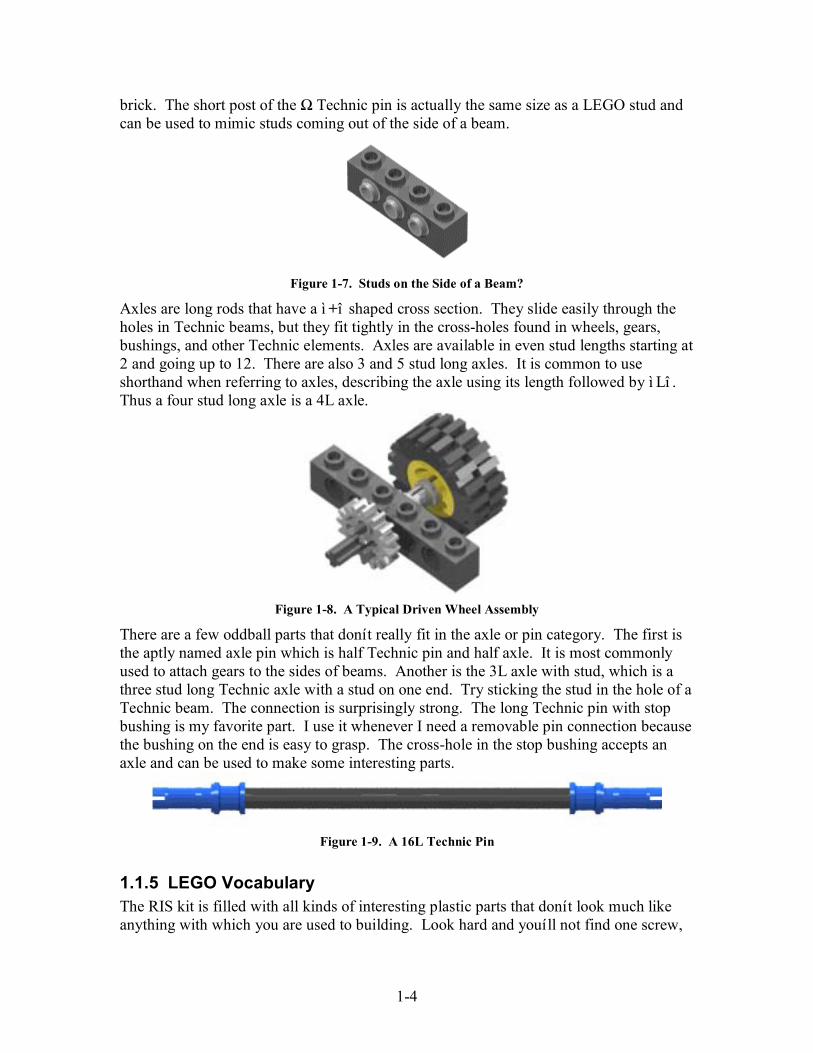
brick. The short post of the Ω Technic pin is actually the same size as a LEGO stud andcan be used to mimic studs coming out of the side of a beam.
Figure 1-7. Studs on the Side of a Beam?
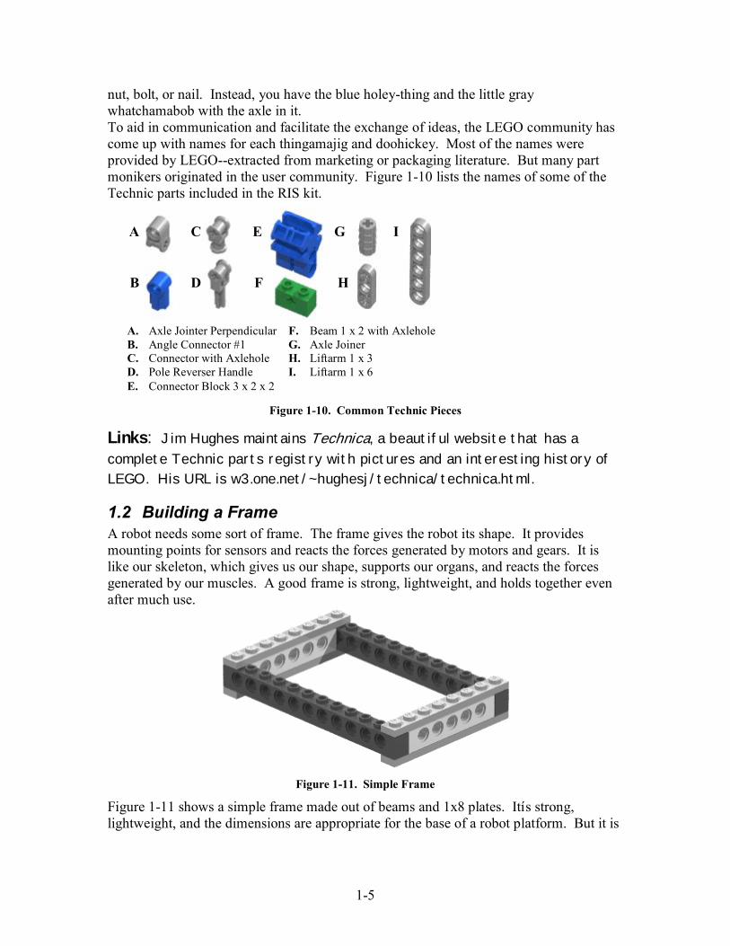
Axles are long rods that have a ì +î shaped cross section. They slide easily through theholes in Technic beams, but they fit tightly in the cross-holes found in wheels, gears,bushings, and other Technic elements. Axles are available in even stud lengths starting at2 and going up to 12. There are also 3 and 5 stud long axles. It is common to useshorthand when referring to axles, describing the axle using its length followed by ì Lî .Thus a four stud long axle is a 4L axle.
Figure 1-8. A Typical Driven Wheel Assembly
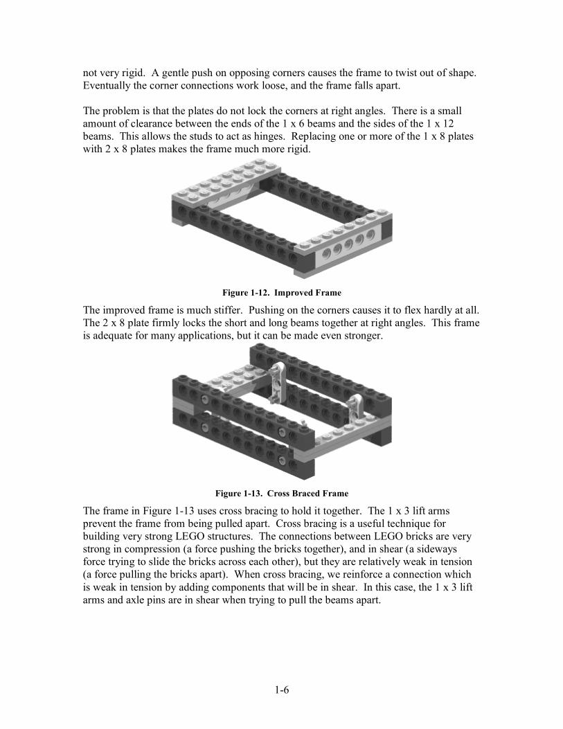
There are a few oddball parts that donít really fit in the axle or pin category. The first isthe aptly named axle pin which is half Technic pin and half axle. It is most commonlyused to attach gears to the sides of beams. Another is the 3L axle with stud, which is athree stud long Technic axle with a stud on one end. Try sticking the stud in the hole of aTechnic beam. The connection is surprisingly strong. The long Technic pin with stopbushing is my favorite part. I use it whenever I need a removable pin connection becausethe bushing on the end is easy to grasp. The cross-hole in the stop bushing accepts anaxle and can be used to make some interesting parts.
Figure 1-9. A 16L Technic Pin
1.1.5 LEGO VocabularyThe RIS kit is filled with all kinds of interesting plastic parts that donít look much likeanything with which you are used to building. Look hard and youíll not find one screw,
1-5
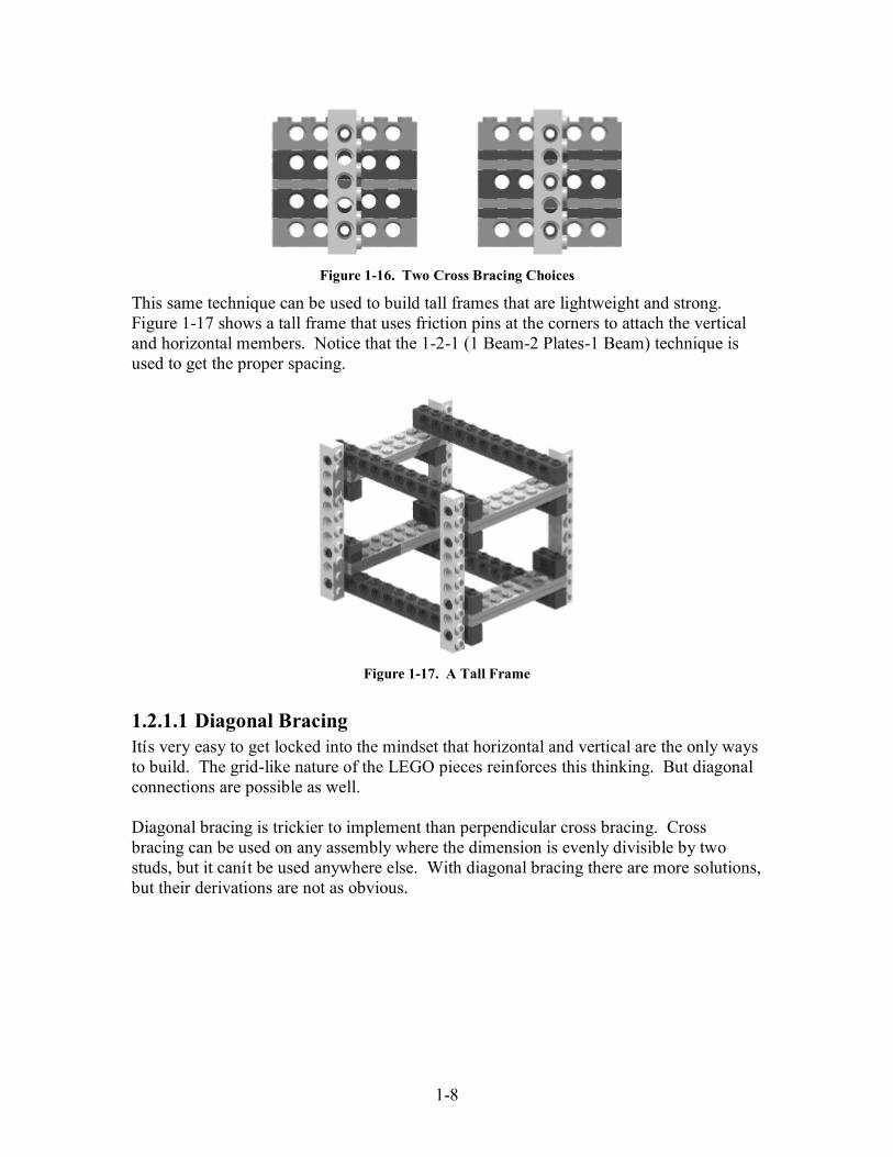
nut, bolt, or nail. Instead, you have the blue holey-thing and the little graywhatchamabob with the axle in it.To aid in communication and facilitate the exchange of ideas, the LEGO community hascome up with names for each thingamajig and doohickey. Most of the names wereprovided by LEGO--extracted from marketing or packaging literature. But many partmonikers originated in the user community. Figure 1-10 lists the names of some of theTechnic parts included in the RIS kit.
Figure 1-10. Common Technic Pieces
Links: Jim Hughes maintains Technica, a beautiful website that has a
complete Technic parts registry with pictures and an interesting history ofLEGO. His URL is w3.one.net/~hughesj/technica/technica.html.
1.2 Building a FrameA robot needs some sort of frame. The frame gives the robot its shape. It providesmounting points for sensors and reacts the forces generated by motors and gears. It islike our skeleton, which gives us our shape, supports our organs, and reacts the forcesgenerated by our muscles. A good frame is strong, lightweight, and holds together evenafter much use.
Figure 1-11. Simple Frame
Figure 1-11 shows a simple frame made out of beams and 1x8 plates. Itís strong,lightweight, and the dimensions are appropriate for the base of a robot platform. But it is
A
B
C
D
E
F
G
H
I
A. Axle Jointer Perpendicular F. Beam 1 x 2 with AxleholeB. Angle Connector #1 G. Axle JoinerC. Connector with Axlehole H. Liftarm 1 x 3D. Pole Reverser Handle I. Liftarm 1 x 6E. Connector Block 3 x 2 x 2
1-6
not very rigid. A gentle push on opposing corners causes the frame to twist out of shape.Eventually the corner connections work loose, and the frame falls apart.
The problem is that the plates do not lock the corners at right angles. There is a smallamount of clearance between the ends of the 1 x 6 beams and the sides of the 1 x 12beams. This allows the studs to act as hinges. Replacing one or more of the 1 x 8 plateswith 2 x 8 plates makes the frame much more rigid.
Figure 1-12. Improved Frame
The improved frame is much stiffer. Pushing on the corners causes it to flex hardly at all.The 2 x 8 plate firmly locks the short and long beams together at right angles. This frameis adequate for many applications, but it can be made even stronger.
Figure 1-13. Cross Braced Frame
The frame in Figure 1-13 uses cross bracing to hold it together. The 1 x 3 lift armsprevent the frame from being pulled apart. Cross bracing is a useful technique forbuilding very strong LEGO structures. The connections between LEGO bricks are verystrong in compression (a force pushing the bricks together), and in shear (a sidewaysforce trying to slide the bricks across each other), but they are relatively weak in tension(a force pulling the bricks apart). When cross bracing, we reinforce a connection whichis weak in tension by adding components that will be in shear. In this case, the 1 x 3 liftarms and axle pins are in shear when trying to pull the beams apart.

1-7
Figure 1-14. Snap On Connections are Weak in Tension
1.2.1 LEGO GeometryA 1 x 6 Technic beam is 1 stud wide, 6 studs long, and 1.2 studs high. Bricks and beamsnot being an integer number of studs high causes problems when trying to do crossbracing. This can be seen in the left assembly in Figure 1-15. The second hole in thevertical beam does not line up with the hole in the horizontal beam.
Figure 1-15. Cross Bracing
In the assembly on the right, the third hole in the vertical beam aligns perfectly with thehole in the horizontal beam. This is because the beam and the two plates add up toexactly two studs tall (1.2 + 2 * 0.4 = 2). You will find that cross bracing only works outwhen the vertical hole spacing is divisible by two.
Question: What is the shortest stack of beams (no plates allowed)
that will align with holes in a vertical beam?
Construction Note: The two assemblies below are the same height, but theone on the right allows for locking the beam at an intermediate point and has
better spacing for vertical meshing of LEGO gears.
Compression Shear Tension
1-8
Figure 1-16. Two Cross Bracing Choices
This same technique can be used to build tall frames that are lightweight and strong.Figure 1-17 shows a tall frame that uses friction pins at the corners to attach the verticaland horizontal members. Notice that the 1-2-1 (1 Beam-2 Plates-1 Beam) technique isused to get the proper spacing.
Figure 1-17. A Tall Frame
1.2.1.1 Diagonal BracingItís very easy to get locked into the mindset that horizontal and vertical are the only waysto build. The grid-like nature of the LEGO pieces reinforces this thinking. But diagonalconnections are possible as well.
Diagonal bracing is trickier to implement than perpendicular cross bracing. Crossbracing can be used on any assembly where the dimension is evenly divisible by twostuds, but it canít be used anywhere else. With diagonal bracing there are more solutions,but their derivations are not as obvious.

1-9
Figure 1-18. Diagonal Cross Bracing
You can find diagonal bracing solutions through experimentation. Lay the diagonalbrace on the part, and move it about until you find a place where the holes line up. It canalso be done analytically using the Pythagorean Theorem for right triangles. ì The sum ofthe squares of the legs of a right triangle equals the square of the hypotenuse.î This isoften written as ì 22 BAC += .î The two legs are the base (width across the bottom)and the height. The hypotenuse is the diagonal beam. Diagonal bracing is possible if thehypotenuse is close to an integer number (less than 0.05 studs difference).
Table 1-1. Calculating Diagonal Lengths
Base (A) Height (B) Hypotenuse Comments
4 4 5.65 Doesnít fit3 4 5 Perfect fit1.5 4.8 5.03 Fits, but a little tight6 8 10 Perfect fit
1.3 SNOTSNOT is all the rage in the LEGO building community today. SNOT, standing for StudsNot On Top, is a way of building with LEGO that does not always utilize the traditionalclick-fit assembly techniques. This can be very tricky and requires great imagination, butthe resulting models are very beautiful and quite realistic.
3
4
1.5
4.8 58
6
1-10
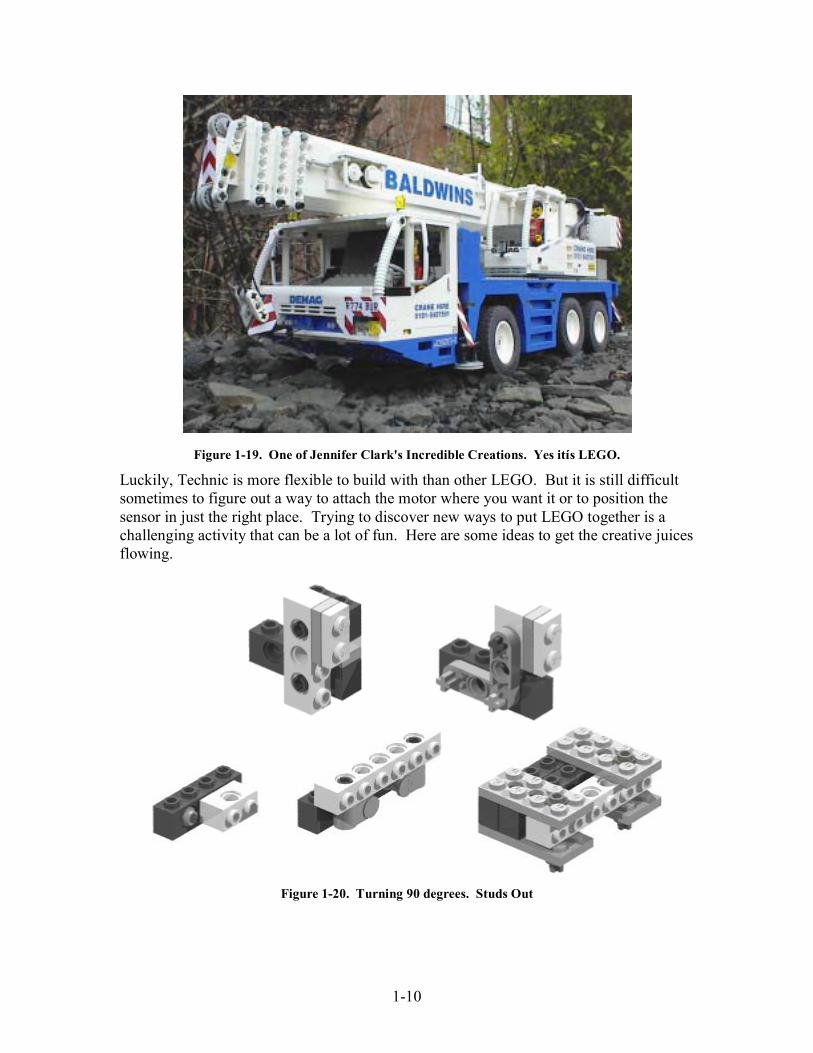
Figure 1-19. One of Jennifer Clark's Incredible Creations. Yes itís LEGO.
Luckily, Technic is more flexible to build with than other LEGO. But it is still difficultsometimes to figure out a way to attach the motor where you want it or to position thesensor in just the right place. Trying to discover new ways to put LEGO together is achallenging activity that can be a lot of fun. Here are some ideas to get the creative juicesflowing.
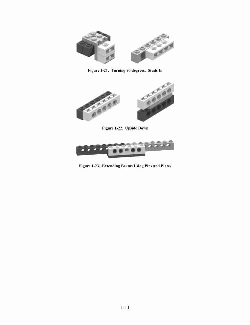
Figure 1-20. Turning 90 degrees. Studs Out
1-11
Figure 1-21. Turning 90 degrees. Studs In
Figure 1-22. Upside Down
Figure 1-23. Extending Beams Using Pins and Plates

2-12
2 GearsEventually you will want to make your robot move. After all, this is not the FLLSculpture Competition! The 9 volt motors provide the motive power, but they may notrun at the right speed or be powerful enough. It may also be too difficult to position themotors where they can be directly attached to the wheels. All these problems can besolved using gears.
Gears are generally used for one of the following reasons:1. To transmit torque from one axle to another2. To increase or decrease the speed of rotation3. To reverse the direction of rotation4. To move rotational motion to a different axis5. To change rotary motion to linear motion6. To keep the rotation of two axles synchronized
2.1 Spur GearsA spur gear is used when shafts must rotate in the same plane. In a spur gear the teeth arestraight and parallel to the shaft. They are by far the most common type of gears, andthey are what most people picture when you mention gears. LEGO includes fourdifferent sized spur gears in the Robotics Invention System.
Figure 2-1 Lego Spur Gears
Gears are normally referred to by their type and the number of teeth. Take, for example,an 8 tooth spur gear. Sometimes a kind of shorthand notation is used where ì toothî isreplaced with ì tî and the type is not specified for spur gears (because they are socommon). For example, a 40 tooth spur gear would be referred to as a 40t gear.
2.1.1 Gear SpacingSizes of LEGO spur gears are shown in Table 2-1. It is interesting to note that the ratioof the radii is equal to the ratio of the tooth count (8/24 = 0.5/1.5 = 1/3). This is becauseall the different sized spur gears have the same sized teeth--even the little 8t gear with itsinvolute profile gear teeth. Having the same sized teeth allows the gears to meshproperly.
24 40168

2-13
Table 2-1. Spur Gear Sizes
Teeth 8 16 24 40Radius (studs) 0.5 1 1.5 2.5
Knowing the radius of a gear and the number of teeth, we can calculate the size of eachtooth. This information can be useful to know when using a spur gear with a gear rack.
Circumference = 2 x Pi x RadiusCircumference = Tooth Size x Tooth CountSize x Count = 2 x Pi x RadiusSize = 2 x Pi x Radius / Count16 tooth = 2 x Pi x 1 / 16
= Pi / 8 studs= 0.392 studs or 3.14 mm
Check it out for yourself. The teeth for each spur gear really do evaluate to the samesize!
2.1.1.1 Horizontal Gear SpacingUsing the information from Figure 2-2, we can calculate the gear spacing required forproper meshing. The distance between the two axles is equal to the sum of the two radii.
8t 16t 24t 40t
8t 1.0 studs 1.5 studs 2.0 studs 3.0 studs
16t 1.5 studs 2.0 studs 2.5 studs 3.5 studs
24t 2.0 studs 2.5 studs 3.0 studs 4.0 studs
40t 3.0 studs 3.5 studs 4.0 studs 5.0 studs
Figure 2-2. Stud Gear Spacing
Combinations using eight, twenty-four, and forty tooth gears are straight forward to setup. Sixteen tooth gears are easy to use with other sixteen tooth gears, but require halfstud spacing to mesh with 8t, 24t, or 40t gears. A two holed 1 x 2 Technic brick can beused to get half stud spacing.

2-14
Figure 2-3. Half Stud Spacing Using 2 Holed 1 x 2 Beam
Construction Notes: Gear spacing of two or three studs provides themaximum number of gear combinations. Two stud spacing also works well in
vertical layouts.
2.1.1.2 Vertical SpacingIt is difficult to mesh gears laid out on a vertical axis. The gear spacing table shows thatproper gear meshing is achieved at half stud intervals starting at 1 stud and going up to 5studs. For good vertical gear meshing, we need to build a structure using 1.2 stud highbeams and 0.4 stud high plates that provides the correct spacing. It works out that 2 and4 studs spacing are the only solutions.
8t 16t 24t 40t8t 2.0 studs16t 2.0 studs24t 2.0 studs 4.0 studs40t 4.0 studs
Figure 2-4. Vertical Gear Spacing
The spacing doesnít have to be perfect for the gears to mesh. Anything within 0.08 studsworks fairly well. The 8 tooth and 16 tooth gears almost fit at 1.6 stud spacing (ideal is1.5 studs), but they donít mesh securely, and it is possible for the gears to slip.

2-15
Figure 2-5. Circumventing Vertical Gear Spacing Restrictions
Figure 2-5 shows one way to get around vertical gear spacing restrictions. The middlegear is held in place by an axle pin in the vertical beam. The top and bottom gears arespaced six studs apart allowing them to fit nicely on axles passing through the horizontalbeams.
2.1.1.3 Diagonal gear spacingDiagonal gear spacing is trickier to calculate than perpendicular or vertical gear spacing.As was done to calculate diagonal cross bracing solutions, Pythagorasís theorem for righttriangles is used to compute the diagonal (hypotenuse). This value is then compared tothe ideal gear spacing information from the table in Figure 2-2.
Figure 2-6. Diagonal Gear Spacing
Table 2-2 shows the possible layouts for 8, 16, 24, and 40 tooth spur gears. Verticaldimensions are displayed in the left hand column, horizontal dimensions in the top row.At the intersection of each row and column is the calculated diagonal gear spacing. Theentry is left blank if this distance does not match the spacing of any of the available gearcombinations. Acceptable gear meshes must be within 0.08 studs of the ideal value.Excessive binding of the gears occurs if the spacing is too small. If the spacing is toogreat, the gear train will have large amounts of backlash, and slippage may occur.
2.8
2
3.44
2-16
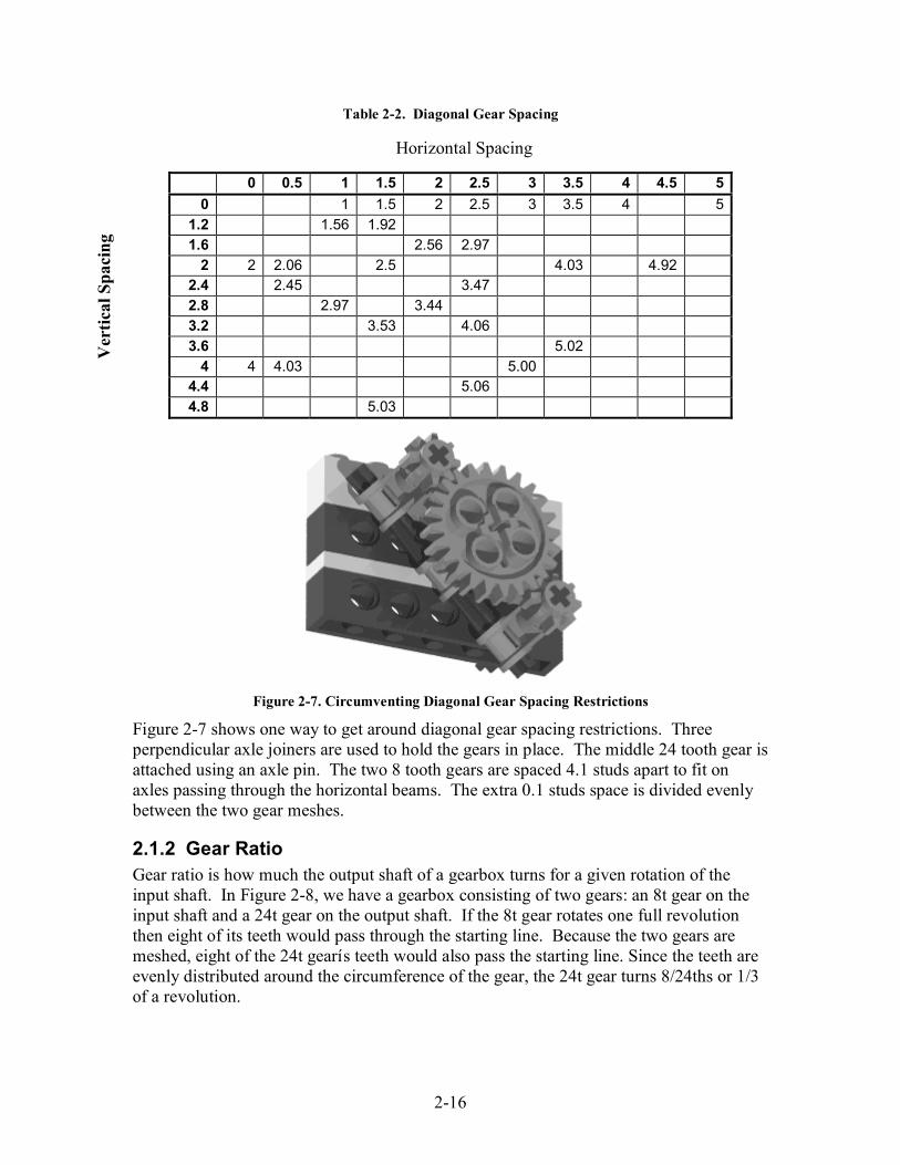
Table 2-2. Diagonal Gear Spacing
0 0.5 1 1.5 2 2.5 3 3.5 4 4.5 5
0 1 1.5 2 2.5 3 3.5 4 5
1.2 1.56 1.92
1.6 2.56 2.97
2 2 2.06 2.5 4.03 4.922.4 2.45 3.47
2.8 2.97 3.44
3.2 3.53 4.06
3.6 5.02
4 4 4.03 5.004.4 5.06
4.8 5.03
Figure 2-7. Circumventing Diagonal Gear Spacing Restrictions
Figure 2-7 shows one way to get around diagonal gear spacing restrictions. Threeperpendicular axle joiners are used to hold the gears in place. The middle 24 tooth gear isattached using an axle pin. The two 8 tooth gears are spaced 4.1 studs apart to fit onaxles passing through the horizontal beams. The extra 0.1 studs space is divided evenlybetween the two gear meshes.
2.1.2 Gear RatioGear ratio is how much the output shaft of a gearbox turns for a given rotation of theinput shaft. In Figure 2-8, we have a gearbox consisting of two gears: an 8t gear on theinput shaft and a 24t gear on the output shaft. If the 8t gear rotates one full revolutionthen eight of its teeth would pass through the starting line. Because the two gears aremeshed, eight of the 24t gearís teeth would also pass the starting line. Since the teeth areevenly distributed around the circumference of the gear, the 24t gear turns 8/24ths or 1/3of a revolution.
Horizontal Spacing
Vertical Spacing

2-17
Figure 2-8. 3:1 Gear Ratio
Using the rotation information we can calculate the gear ratio. Following popularconvention, it is expressed as a ratio of whole numbers.
Gear Ratio = 1 : 1/3= 3 : 1
The 3:1 gear ratio tells us that the input shaft (attached to the 8t gear) has to completethree full revolutions for the output shaft (attached to the 24t gear) to rotate all the wayaround just once. Using gears to slow down rate of rotation or decrease the amount ofrotation is called gearing down. If we were to switch the 8t and 24t gears around, theoutput shaft would spin three revolutions for each revolution of the input shaft. This isgearing up, and the gear ratio would be 1:3.
You may have noticed that the gear ratio is the inverse of the ratio of the number of gearteeth. The reason for this is easier to see if we recalculate the gear ratio using an inputshaft rotation of only 1 tooth. In the case of the 8t gear driving the 24t gear, the inputshaft would turn 1/8 of a revolution and the output shaft 1/24 of a revolution.
Gear Ratio = 1/8 : 1/24= 24 : 8= 3 : 1
Using gear tooth counts to directly calculate gear ratios is easier and faster thancalculating the rotations first and then using these values to derive the gear ratio.
1 rev8 teeth
1/3 rev8 teeth

2-18
Table 2-3. Gear Ratios for LEGO Spur Gears
8t 16t 24t 40t
8t 1:1 2:1 3:1 5:1
16t 1:2 1:1 3:2 5:2
24t 1:3 2:3 1:1 5:3
40t 1:5 2:5 3:5 1:1
Links: Ted Cochran has a nice treatment of gear ratios with Minnesota FLL
examples at www.hightechkids.org/fll/coaching/Gears/gears.htm.
2.1.3 TorqueTorque is a force that tends to rotate or turn things. You generate a torque any time youapply a force to the handle of a wrench. This force creates a torque on the nut, whichtends to turn the nut. If the nut is too tight, you either pull harder (more force), or get alonger handled wrench (more distance).
Figure 2-9. Torque = Force x Distance
From the wrench example, we see that torque is a product of force and distance. Theunits used when measuring torque reflect this. In the U. S. we measure torque in foot-pounds (ft-lbs). Newton-meters (Nm) is the unit of torque in the metric system.
Distance
Torque Force
16 : 8or2 : 1
24 : 8or3 : 1
40 : 8or5 : 1
Output Shaft or Driven Gear
Input Shaft or
Driving Gear
2-19
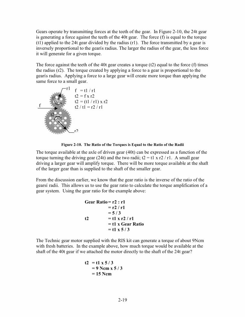
Gears operate by transmitting forces at the teeth of the gear. In Figure 2-10, the 24t gearis generating a force against the teeth of the 40t gear. The force (f) is equal to the torque(t1) applied to the 24t gear divided by the radius (r1). The force transmitted by a gear isinversely proportional to the gearís radius. The larger the radius of the gear, the less forceit will generate for a given torque.
The force against the teeth of the 40t gear creates a torque (t2) equal to the force (f) timesthe radius (r2). The torque created by applying a force to a gear is proportional to thegearís radius. Applying a force to a large gear will create more torque than applying thesame force to a small gear.
Figure 2-10. The Ratio of the Torques is Equal to the Ratio of the Radii
The torque available at the axle of driven gear (40t) can be expressed as a function of thetorque turning the driving gear (24t) and the two radii; t2 = t1 x r2 / r1. A small geardriving a larger gear will amplify torque. There will be more torque available at the shaftof the larger gear than is supplied to the shaft of the smaller gear.
From the discussion earlier, we know that the gear ratio is the inverse of the ratio of thegearsí radii. This allows us to use the gear ratio to calculate the torque amplification of agear system. Using the gear ratio for the example above:
Gear Ratio= r2 : r1= r2 / r1= 5 / 3
t2 = t1 x r2 / r1= t1 x Gear Ratio= t1 x 5 / 3
The Technic gear motor supplied with the RIS kit can generate a torque of about 9Ncmwith fresh batteries. In the example above, how much torque would be available at theshaft of the 40t gear if we attached the motor directly to the shaft of the 24t gear?
t2 = t1 x 5 / 3= 9 Ncm x 5 / 3= 15 Ncm
r1
r2
t2
t1
f
f = t1 / r1t2 = f x r2t2 = (t1 / r1) x r2t2 / t1 = r2 / r1

2-20
2.1.4 SpeedWhen using simple machines like gears (or any kind of machine for that matter) younever get something for nothing. In our prior example, we used gears to increase torque.What we traded to get the torque increase was speed. The output shaft may turn stronger,but it also turns slower.
If we measure the angles in radians (1 radian = 180 degrees / Pi = 1 revolution / (2 x Pi)),the tooth velocity of a gear (v) is equal to the angular velocity (ω) times the radius (r).There is a proportional relationship between the radius and the tooth velocity. At a givenangular velocity, the teeth of a larger gear will travel faster than the teeth of a smallergear.
Figure 2-11. Ratio of Angular Velocities is Equal to Inverse Ratio of the Radii
When two gears are meshed, the tooth velocity for each gear is the same. In the exampleabove, what is the angular velocity of the 40t gear if the 24t gear is spinning at 180 rpm?
r1 = 1.5 studs = 12 mmr2 = 2.5 studs = 20 mmω1 = 180 rpm= 180 revolutions / minute x 1 minute / 60 seconds= 3 revolutions / second= 3 revolutions / second x 2 Pi radians / revolution= 6 Pi radians / second= 18.85 radians / second
v = ω1 x r1= 18.85 radians / second x 12mm / radian= 226.19 mm / second
ω2 = v / r2= (226.19 mm /second) / (20 mm / radian)= 11.31 radians / second= 1.8 revolutions / second= 108 rpm
The larger gear spins more slowly than the smaller gear. The ratio of the angularvelocities is equal to the inverse of the ratio of the radii. Knowing this we can calculatethe angular velocity using the radius ratio directly.
r2
r1
ω1
ω 2
v
v = ω1 x r1ω2 = v / r2ω2 = (ω1 x r1) / r2
= ω1 x r1 / r2ω2 / ω1 = r1 / r2

2-21
ω2 = ω1 x r1 / r2= 180 rpm x 1.5 studs / 2.5 studs= 108 rpm
Just as with torque, the gear ratio can be used in place of the ratio of the radii.
Gear Ratio = r2 : r1= r2 / r1= 5 / 3
ω2 = ω1 x r1 / r2= ω1 x (1 / Gear Ratio)= ω1 / Gear Ratio= 180 rpm / (5 / 3)= 180 rpm x 3 / 5= 108 rpm
Links: How Stuff Works, one of the best sites on the web, has a wonderful
article about gears, gear ratios, torque, and speed. Check it out at
“www.howstuffworks.lycozone.com”.
2.1.5 Gear TrainsIf a number of gears are cascaded so that several meshes relate an input to an output, agear train is formed. Using four 40t and four 8t gears, it is possible to create a gear ratioof 625:1.
Figure 2-12. Multi-stage Gear Train
The gear train above consists of four stages, each having a 5:1 gear ratio. To calculate theoverall gear reduction, we start with the gear ratio between A and B, multiply that timesthe ratio between B and C, and so on until we get to E.
A C E DB
2-22
A→B = 5:1B→C = 5:1C→D = 5:1D→E = 5:1A→E = A→B x B→C x C→D x D→E
= 5:1 x 5:1 x 5:1 x 5:1= 5 x 5 x 5 x 5:1 x 1 x 1 x 1= 625:1
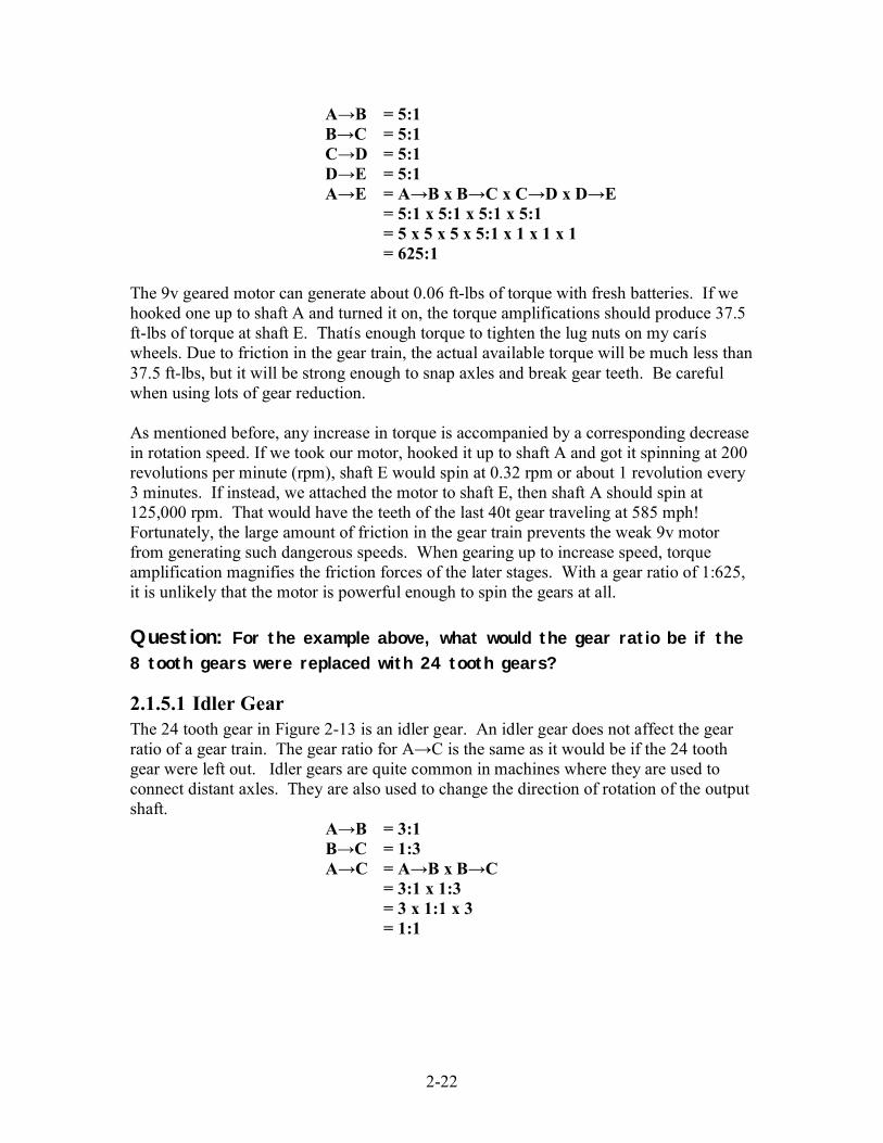
The 9v geared motor can generate about 0.06 ft-lbs of torque with fresh batteries. If wehooked one up to shaft A and turned it on, the torque amplifications should produce 37.5ft-lbs of torque at shaft E. Thatís enough torque to tighten the lug nuts on my caríswheels. Due to friction in the gear train, the actual available torque will be much less than37.5 ft-lbs, but it will be strong enough to snap axles and break gear teeth. Be carefulwhen using lots of gear reduction.
As mentioned before, any increase in torque is accompanied by a corresponding decreasein rotation speed. If we took our motor, hooked it up to shaft A and got it spinning at 200revolutions per minute (rpm), shaft E would spin at 0.32 rpm or about 1 revolution every3 minutes. If instead, we attached the motor to shaft E, then shaft A should spin at125,000 rpm. That would have the teeth of the last 40t gear traveling at 585 mph!Fortunately, the large amount of friction in the gear train prevents the weak 9v motorfrom generating such dangerous speeds. When gearing up to increase speed, torqueamplification magnifies the friction forces of the later stages. With a gear ratio of 1:625,it is unlikely that the motor is powerful enough to spin the gears at all.
Question: For the example above, what would the gear ratio be if the
8 tooth gears were replaced with 24 tooth gears?
2.1.5.1 Idler GearThe 24 tooth gear in Figure 2-13 is an idler gear. An idler gear does not affect the gearratio of a gear train. The gear ratio for A→C is the same as it would be if the 24 toothgear were left out. Idler gears are quite common in machines where they are used toconnect distant axles. They are also used to change the direction of rotation of the outputshaft.
A→B = 3:1B→C = 1:3A→C = A→B x B→C
= 3:1 x 1:3= 3 x 1:1 x 3= 1:1

2-23
Figure 2-13. Idler Gear
2.1.6 Clutch GearThe funny looking white 24 tooth spur gear with the writing on its face is the clutch gear.The clutch gear is special in that the gear teeth are able to rotate about the shaft. It has aninternal clutch mechanism that starts to slip when its maximum rated torque is exceeded.The clutch gear is used to limit the torque of a geared system, saving motors andpreventing your robot from tearing itself apart.
The clutch gear has ì 2.5.5 Ncmî stamped on its face. This is the torque rating of theclutch. Ncm stands for Newton Centimeter, a unit of torque (torque is a product of forceand distance, centimeter is a unit of distance, and Newton is a unit of force). The clutchgear can transmit a maximum torque of from 2.5 to 5 Ncm (0.018 to 0.037 ft lbs or 0.22to 0.44 in lbs).
Figure 2-14. Using Clutch Gear to Limit Forces
In Figure 2-14, the clutch gear is used to limit the force of the lift arm pressing againstthe connector peg stops. Without the clutch gear, we would run the risk of stalling amotor or damaging the assembly. Using the information we have about the clutch gear,gear ratios, and distance, itís possible to calculate the maximum force the lift arm cangenerate to push against the connector peg.
A max torque = 5 NcmGear ratio A:B = 5:3B max torque = A torque x Gear Ratio
= 5 Ncm x 5 / 3= 8.33 Ncm
24 mmBA
A B C

2-24
Distance B to Pin= 3 studs= 24 mm or 2.4 cm
Max force at Pin = B torque / Distance= 8.33 Ncm / 2.4 cm= 3.47 N or 0.78 lbs
2.2 Crown GearThe crown gear has teeth that are raised on one side and rounded off on the other. Thisgives it a crown-like appearance. The crown gear is used when the shafts to be turnedmeet at an angle--usually a right angle. The crown gear can be meshed to spur gears andworm gears, but it doesnít mesh well with other crown gears. The crown gear can also beused in place of a 24 tooth spur gear.
Figure 2-15. Crown Gear
Treat the crown gear just like the 24t spur gear when computing gear reduction. For thegearbox above, if the 8t gear is attached to the input shaft, and the 24t spur gear to theoutput shaft, the gear ratio is:
Gear Ratio = 24:8 x 24:24= 3:1 x 1:1= 3:1
2.3 Bevel GearThe bevel gear has teeth that slope along one surface of the disc. It is used when theshafts to be turned meet at an angle--usually a right angle. It has less friction than thecrown gear, but it can only mesh with another bevel gear. LEGO produces 12 tooth, 14tooth, and 20 tooth bevel gears. Unfortunately, only the 12 tooth bevel gear is includedin the RIS kit.
Figure 2-16. Bevel Gear

2-25
The old 14 tooth bevel gears have a problem with their thin faceted teeth breaking. The12 tooth bevel gear has a circular backing plate that strengthens the gear teeth to preventthis from happening. The backing plate gives the gear a smooth circular outline andallows it to be used as a very small wheel.
Figure 2-17. A Small Wheel Built from Two 12t Bevel Gears
Question: A wheel made out of bevel gears would not have much
traction. For what applications could this be a benefit?
2.4 Worm GearA worm gear is a screw that usually turns along a spur gear. Motion is transmittedbetween shafts that are at right angles. If you want to create a high gear ratio, nothingbeats a worm gear. Each time the shaft spins one revolution, the spur gear moves onetooth forward. If the spur gear has 24 teeth, you have a 24:1 gear ratio in a very smallpackage.
Figure 2-18. Worm Gear
The efficiency of a worm gear system is much lower than that of normal meshes becausethe worm works primarily by sliding, thus increasing frictional losses. This has anunusual side effect in that the worm gear is asymmetric and self-locking. You can turnthe input shaft to drive the output shaft, but you cannot turn the output shaft to drive theinput shaft.

2-26
Figure 2-19. Using the Worm Gear's Self Locking Feature
The mechanism in Figure 2-19 makes use of the worm gearís self-locking feature to holdthe bucket in place. The axle through the worm gear can be turned to raise or lower thebucket. Once in place, no torque is required to maintain the position.
The worm gear can also be used to implement a lead screw. Lead screws convert rotarymotion to linear motion. A lead screw consists of a threaded rod and a captured nut.Spinning the rod causes the nut to move along the length of the rod. Lead screws areused in many devices. One of the most visible examples is the Genie garage door opener.
Figure 2-20. LEGO Lead Screw
Figure 2-20 is a LEGO implementation of a lead screw. The threaded rod is constructedof multiple worm gears on the center axle. The half bushings on the outer axles make upthe captured nut. Spinning the center axle causes the outer axles to move in or out.
Construction Note: Be careful when constructing a threaded rod out ofworm gears. You can put two worm gears on an axle in four different ways,
but only one results in a continuous thread.
Good Bad
2-27
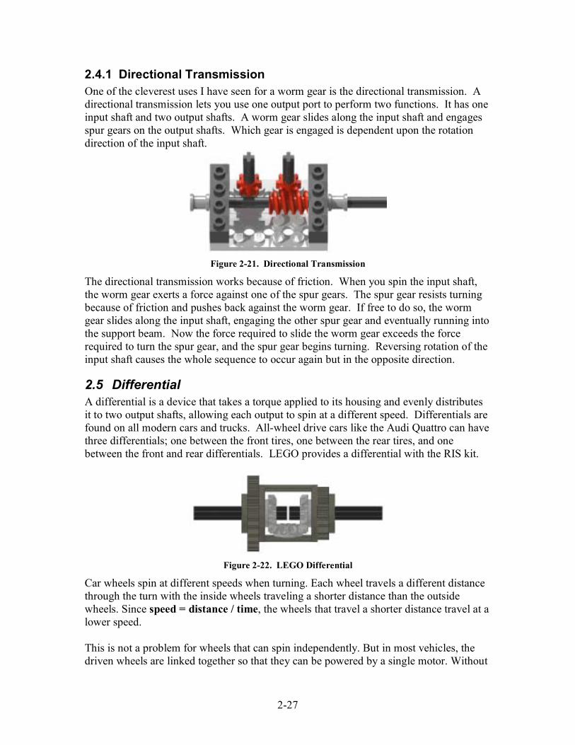
2.4.1 Directional TransmissionOne of the cleverest uses I have seen for a worm gear is the directional transmission. Adirectional transmission lets you use one output port to perform two functions. It has oneinput shaft and two output shafts. A worm gear slides along the input shaft and engagesspur gears on the output shafts. Which gear is engaged is dependent upon the rotationdirection of the input shaft.
Figure 2-21. Directional Transmission
The directional transmission works because of friction. When you spin the input shaft,the worm gear exerts a force against one of the spur gears. The spur gear resists turningbecause of friction and pushes back against the worm gear. If free to do so, the wormgear slides along the input shaft, engaging the other spur gear and eventually running intothe support beam. Now the force required to slide the worm gear exceeds the forcerequired to turn the spur gear, and the spur gear begins turning. Reversing rotation of theinput shaft causes the whole sequence to occur again but in the opposite direction.
2.5 DifferentialA differential is a device that takes a torque applied to its housing and evenly distributesit to two output shafts, allowing each output to spin at a different speed. Differentials arefound on all modern cars and trucks. All-wheel drive cars like the Audi Quattro can havethree differentials; one between the front tires, one between the rear tires, and onebetween the front and rear differentials. LEGO provides a differential with the RIS kit.
Figure 2-22. LEGO Differential
Car wheels spin at different speeds when turning. Each wheel travels a different distancethrough the turn with the inside wheels traveling a shorter distance than the outsidewheels. Since speed = distance / time, the wheels that travel a shorter distance travel at alower speed.
This is not a problem for wheels that can spin independently. But in most vehicles, thedriven wheels are linked together so that they can be powered by a single motor. Without
2-28
a differential, the wheels would be locked together, forced to spin at the same speed. Thiswould make turning difficult. For the car to be able to turn, one wheel would have to slip,which can require great force.
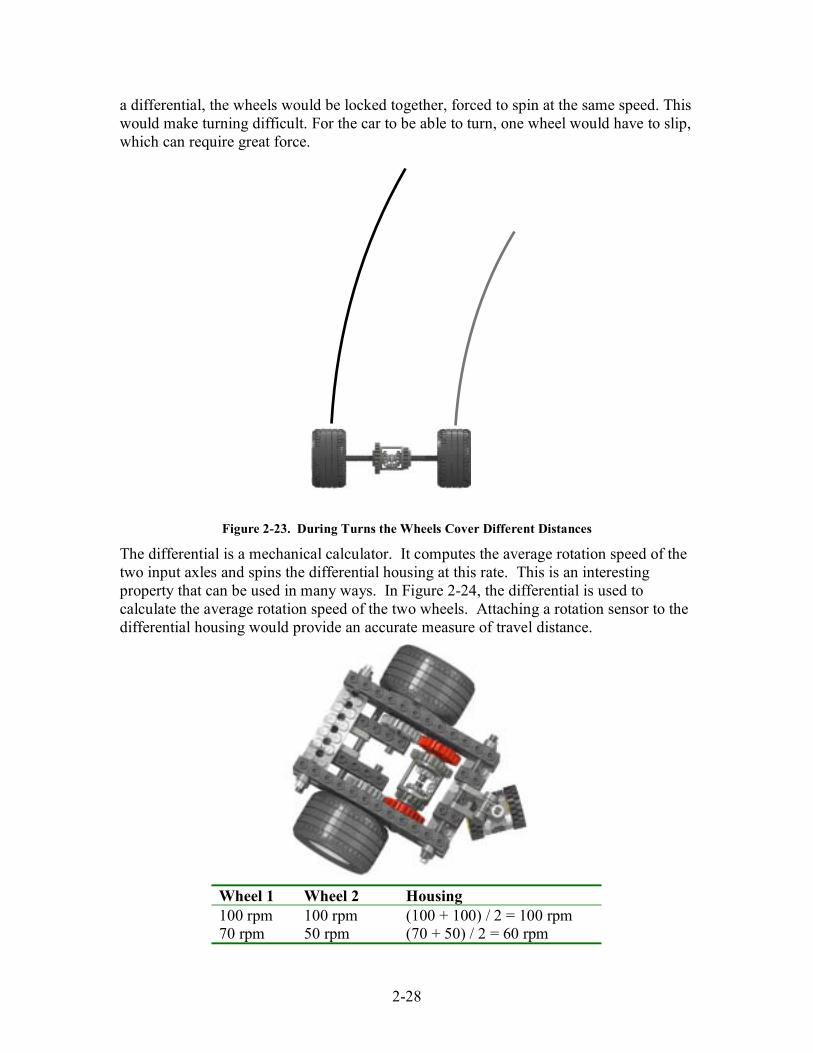
Figure 2-23. During Turns the Wheels Cover Different Distances
The differential is a mechanical calculator. It computes the average rotation speed of thetwo input axles and spins the differential housing at this rate. This is an interestingproperty that can be used in many ways. In Figure 2-24, the differential is used tocalculate the average rotation speed of the two wheels. Attaching a rotation sensor to thedifferential housing would provide an accurate measure of travel distance.
Wheel 1 Wheel 2 Housing100 rpm 100 rpm (100 + 100) / 2 = 100 rpm70 rpm 50 rpm (70 + 50) / 2 = 60 rpm

2-29
80 rpm -80 rpm (80 ñ 80) / 2 = 0 rpm
Figure 2-24. Using Differential to Calculate Average Rotation
The platform below uses the differential to measure the difference in rotation speedbetween the two axles. Notice the extra gear between the differential and the wheel onthe right side. It reverses the direction of rotation for the right differential shaft. Arotation sensor could be used here to measure turning.
Wheel 1 Wheel 2 Housing100 rpm 100 rpm (100 - 100) / 2 = 0 rpm70 rpm 50 rpm (70 - 50) / 2 = 10 rpm80 rpm -80 rpm (80 + 80) / 2 = 80 rpm
Figure 2-25. Using a Differential to Calculate Difference in Rotation
2.5.1 Ratchet SplitterAn intriguing use for the differential is as part of a ratchet splitter. A ratchet splitter letsyou perform two different functions with a single motor, just like the directionaltransmission. But instead of using friction to switch gears, the ratchet splitter uses aratcheting mechanism to prevent an axle from spinning in both directions.

2-30
Figure 2-26. Ratchet Splitter
The assembly in Figure 2-26 is part of a differential drive car I built that used a singlemotor to provide both locomotion and steering. The perpendicular axle joiner and 24tgear is a ratcheting mechanism that prevents the right axle from rotating counterclockwise. When the motor turns clockwise, the left and right axles turn in the samedirection and propel the vehicle forward. When the motor turns counter clockwise, theratchet locks the right wheel, and the vehicle turns to the right as it backs up.
Question: What would happen if a second ratchet was added to
prevent the left axle from turning clockwise?
2.6 Gear RackThe gear rack looks like a spur gear laid out flat. It is usually used in conjunction with aspur gear (which is referred to as the pinion). Rack and pinion gears are used to convertrotation into linear motion. An example of this is the steering system on many cars. Thesteering wheel rotates a gear that engages the rack. As the gear turns, it slides the rackeither to the right or left depending on which way you turn the steering wheel. Themotion is transmitted via linkages to the front wheels causing them to pivot.
Figure 2-27. LEGO Gear Rack and Pinion
One of the trickier problems encountered when using the gear rack is how to provide asmooth surface upon which the rack can slide. Most LEGO car models solve thisproblem with tiles, which are plates without studs on top. Figure 2-27 uses two 1 x 5 liftarms to provide a smooth surface. An upside down Technic beam is another commonlyused solution.

2-31
2.7 PulleysA pulley is a wheel with a groove about its diameter. The groove, called the race, acceptsa belt which attaches the pulley to other pulleys. As the pulley rotates, friction forces pullon the belt putting it in tension. The belt transmits the force to the other pulley causing itto rotate.
Figure 2-28. Pulleys and Belts
LEGO includes four sizes of pulleys in the RIS--the half bushing, the small pulley, thepulley wheel, and the large pulley. Pulleys are connected using belts that rest in thepulleysí races. LEGO belts are color coded: small (white), medium (blue), and large(yellow). The black rubber bands can be used as belts, but they are more elastic than theLEGO belts, and their rectangular cross section doesnít fit well in a pulleyís race.
Figure 2-29. Lego Pulleys
With four different sized pulleys, it is possible to ì gearî up and ì gearî down. Thereduction ratio with pulleys is determined by the ratio between their diameters. The trickis determining exactly where to measure the diameter. Table 2-4 shows pulley diametersmeasured at the bottom of the race. The resulting reduction ratios are close to the valuesdetermined experimentally in Table 2-5.
Table 2-4. Measured pulley diameters
DiameterHalfBushing
SmallPulley
MediumPulley
LargePulley
Millimeters 5.7 8.7 22 34.5Studs 0.71 1.09 2.75 4.3

2-32
Table 2-5. Pulley Ratios
HalfBushing
SmallPulley
MediumPulley
LargePulley
Half Bushing 1:1 3:2 7:2 6:1Small Pulley 2:3 1:1 7:3 4:1Medium Pulley 2:7 3:7 1:1 5:3Large Pulley 1:6 1:4 3:5 1:1
2.7.1 TorquePulleys may be used in place of gears in many applications. Since there are no teeth tomesh, placement is much more forgiving. But because it has no teeth, a pulley cannot beused to transmit high torques. The belt will slip first. Determining when and how muchthe belt will slip is difficult. It depends on many factors such as the size of the pulleys,the tension of the belt, and the friction between the pulley and the belt.
You can increase the torque capacity of a pulley system by increasing the reduction ratioor by increasing the friction between the pulleys and the belt. Increasing the reductionratio may not be desirable because it has an associated decrease in speed. Friction can beincreased either by using a tighter belt or by increasing the contact area between thepulleys and the belt.
Figure 2-30. Two ways to Increase Torque Capacity
Question: How else can we increase the friction between the pulleys
and the belt?
Some enterprising robot designers use belt slippage as a torque limiting device, similar tothe clutch gear. Because slippage is difficult to predict, it is best to use experimentationto find the belt and pulley combination that will slip at the desired torque.

2-33
Figure 2-31. Using Pulleys to Limit Torque
Construction Notes: The tank tread and sprocket can be used like a pulley
and belt system. The tread’s teeth prevent slipping even if a large torque isapplied to the sprocket.
2.8 Reinforcing gear trainsThe components of the gear train are likely to experience the largest forces of anything inyour robot. The motor will stall and wheels will slip before forces get too out of hand.But with enough gear reduction, it is easy to generate forces that will tear a gearbox apart.
Figure 2-32. Forces on gears
Different types of gears require different kinds of support. In spur gears, forces areapplied perpendicular to the axles. Unless the axles are properly supported, they will bepushed apart when high torques are applied. Supporting the axles is not a problem inhorizontal layouts, but vertical and diagonal layouts may require additional bracing.
Crown and bevel gears have forces directed perpendicular and parallel to their axles. Aswith spur gears, the supporting structure will probably require bracing to hold the axles inplace. This can be difficult at times because the supports are perpendicular to each other.Crown and bevel gears also require a solid backing to prevent them from sliding on theiraxles.
The most difficult problem with the worm gear is locking the worm screw in place on itsaxle. This is exacerbated by the gearís odd length (itís 15.5mm long instead of the 16mm

2-34
required for a perfect fit). When the worm gear is used with a spur gear, the spur gearísaxle must be well supported.
Figure 2-33. Gearboxes Donít Have to be Big to be Strong
2.9 BacklashThe backlash of a gear train is the amount the input shaft can rotate without moving theoutput shaft. Backlash is caused by the gears not meshing perfectly (see Figure 2-34). Inthis example, when gear A reverses rotation, the tooth on gear B goes from being loadedon the left side to being loaded on the right side. Because of the gap between the teeth, Awill be able to rotate a small amount before B notices the change in direction.
Figure 2-34. Backlash is caused by poor gear meshing
Backlash introduces discontinuity, uncertainty, and impact in mechanical systems. Thismakes accurate control difficult. Positioning accuracy is also compromised due tobacklash. A large amount of backlash makes a robot feel sloppy and gives an overallimpression of poor engineering (you want to impress those judges).
In industry, backlash is reduced by using specially mated gears that are designed to meshperfectly. LEGO gears are designed to work with a wide variety of gears of differentsizes and designs. This limits how perfectly they can fit together. Luckily, there areother ways to minimize backlash and its effects.

2-35
Reducing Backlash:1. Place rotation sensors near the output shaft. This minimizes the effect backlashhas on the sensor readings. Unfortunately, it also limits your ability to increasesensor resolution by gearing up.
2. Use large gears. Backlash is less noticeable in larger gears.3. Minimize the number of gears in a gear train. The larger the number of meshes,the greater the backlash.
4. Backlash increases when you gear up and decreases when you gear down.5. When laying out gears diagonally, keep gear spacing near the ideal values.Backlash increases if the gears are too far apart.
6. Be careful when using the worm gear. The worm gearís odd size (1.94 studslong) makes it difficult to support. Multiple half bushings can be used to hold theworm gear in place for lightly loaded applications.
An interesting alternative is to prevent backlash from occurring. You can take the playout of a gear train by applying a torque to the output shaft, trading some input torque formore precision. If the torque is great enough, it prevents backlash from happening whenchanging direction. In Figure 2-35, the rubber band is supplying the force used topreload the gear train.
Figure 2-35. Preloading a gear train with a rubber band
Some high precision machines use a split gear to minimize backlash. A split gear lookslike a spur gear that has been cut through the middle about its circumference. Springs areplaced in channels between two gears. The springs push the gears apart radially. Whenmeshed to another gear, the spring is compressed providing a preload force.

2-36
Figure 2-36. Split gear made from LEGO
Figure 2-36 shows a split gear made out of LEGO parts. It uses the axles instead ofsprings to provide the preload force. When assembling, the 40t gears are twisted onetooth relative to each other before meshing them to the 8t gears.

3-37
3 WheelsFLL challenges involved moving around and picking up things, moving around anddropping things, moving around and triggering things. All this moving around requiressome sort of mobile platform, and most of the mobile platforms use wheels.
Wheels support the weight of the robot and transmit the power of the motors to theground. What wheels you use will affect your robotís speed, power, accuracy, and abilityto handle variations in terrain. Wheel choices will have a profound effect on your robotíssuccess or failure.
3.1 SizesLEGO has supplied a wide variety of wheels and tires in the RIS kit. There are threesizes of solid rubber tires which all fit on the same plastic wheel and three sizes ofballoon tires that fit on differently sized hubs. Dimensions in millimeters are stamped onthe sidewall of the balloon tires. Dimensions for the solid tires are not available,therefore, approximate dimensions are supplied in the figure below.
Figure 3-1. Lego Wheels and Tires
The diameter of the wheels chosen will, in a large part, determine how fast and powerfulyour robot is. Large wheels will make a robot run faster but decrease its towing capacity.Small wheels will give you more power but with a corresponding decrease in speed.
3.1.1 SpeedAs you drive down the highway the speed your car travels is dependent upon therotational speed of the engine, the gear ratio of the transmission, and the diameter of thetires. The engine speed and gear ratio define how fast the drive wheels are spinning
Small Solid24mm x 7mm
Medium Solid30mm x 10.7mm Large Solid
43mm x 10.7mm
Large Balloon81.6mm x 15mm
Small Balloon30.4 mm x 14
Medium Balloon49.6 mm x 28 mm
Pulley Wheel30 mm x 4 mm

3-38
(their angular velocity). The angular velocity can then be converted to linear velocityusing the equation for the circumference of a circle (distance around the circle).
I am driving down the highway in my trusty Camry with the broken speedometer cablewhen I see a police car with its lights on. A quick look at the instruments shows theengine is at 800 rpm and that I am in third gear. Am I going to get a ticket?
I know (because I diligently read the owners manual) that the gear ratio for my automatictransmission is 1:1 in third gear. I also know that the tires are 24.6î in diameter. So whatis the speed?
ω = Engine RPM x Gear Ratio= 800 rpm x 1:1= 800 rpm
v = ω x Pi x d= 800 rpm x 3.14 x 24.6 inches= 61826 inches per minute
= 58.5 mph ! I think I’m OK
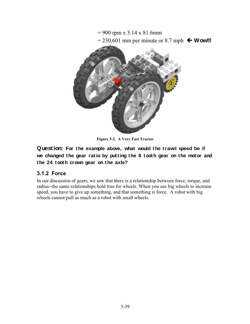
The same equations can be used to calculate the expected travel speed of your robot. Forexample, letís use the robot shown in Figure 3-2. It has one 9v motor that is geared up bya factor of 3:1 (a 24 tooth crown gear driving an 8 tooth spur gear). It uses the big 81.6 x15 balloon tires to make it go really fast. The motor should be able to reach 300 rpm fora lightly loaded structure like this. What is the expected speed?
ω = Motor RPM x Gear Ratio= 300 rpm x 3:1= 900 rpm
v = ω x Pi x d
vd
ωv = ω x Pi x d
Circumference
Diameter 1 Revolution
Circumference = Pi x Diameter
3-39
= 900 rpm x 3.14 x 81.6mm
= 230,601 mm per minute or 8.7 mph ! Wow!!!
Figure 3-2. A Very Fast Tractor
Question: For the example above, what would the travel speed be if
we changed the gear ratio by putting the 8 tooth gear on the motor andthe 24 tooth crown gear on the axle?
3.1.2 ForceIn our discussion of gears, we saw that there is a relationship between force, torque, andradius--the same relationships hold true for wheels. When you use big wheels to increasespeed, you have to give up something, and that something is force. A robot with bigwheels cannot pull as much as a robot with small wheels.
3-40
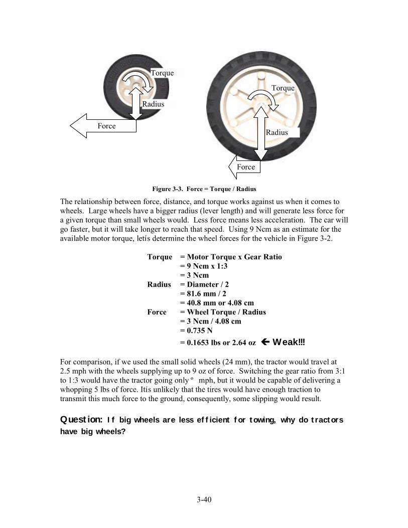
Figure 3-3. Force = Torque / Radius
The relationship between force, distance, and torque works against us when it comes towheels. Large wheels have a bigger radius (lever length) and will generate less force fora given torque than small wheels would. Less force means less acceleration. The car willgo faster, but it will take longer to reach that speed. Using 9 Ncm as an estimate for theavailable motor torque, letís determine the wheel forces for the vehicle in Figure 3-2.
Torque = Motor Torque x Gear Ratio= 9 Ncm x 1:3= 3 Ncm
Radius = Diameter / 2= 81.6 mm / 2= 40.8 mm or 4.08 cm
Force = Wheel Torque / Radius= 3 Ncm / 4.08 cm= 0.735 N
= 0.1653 lbs or 2.64 oz ! Weak!!!
For comparison, if we used the small solid wheels (24 mm), the tractor would travel at2.5 mph with the wheels supplying up to 9 oz of force. Switching the gear ratio from 3:1to 1:3 would have the tractor going only º mph, but it would be capable of delivering awhopping 5 lbs of force. Itís unlikely that the tires would have enough traction totransmit this much force to the ground, consequently, some slipping would result.
Question: If big wheels are less efficient for towing, why do tractors
have big wheels?
Force
Torque
Radius
Radius
Torque
Force
3-41
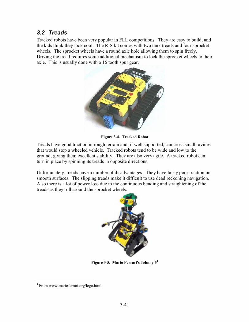
3.2 TreadsTracked robots have been very popular in FLL competitions. They are easy to build, andthe kids think they look cool. The RIS kit comes with two tank treads and four sprocketwheels. The sprocket wheels have a round axle hole allowing them to spin freely.Driving the tread requires some additional mechanism to lock the sprocket wheels to theiraxle. This is usually done with a 16 tooth spur gear.
Figure 3-4. Tracked Robot
Treads have good traction in rough terrain and, if well supported, can cross small ravinesthat would stop a wheeled vehicle. Tracked robots tend to be wide and low to theground, giving them excellent stability. They are also very agile. A tracked robot canturn in place by spinning its treads in opposite directions.
Unfortunately, treads have a number of disadvantages. They have fairly poor traction onsmooth surfaces. The slipping treads make it difficult to use dead reckoning navigation.Also there is a lot of power loss due to the continuous bending and straightening of thetreads as they roll around the sprocket wheels.
Figure 3-5. Mario Ferrari's Johnny 54
4 From www.marioferrari.org/lego.html

3-42
Only one size track is included in the RIS kit. For the track not to slip, the spacingbetween the sprockets must be large enough to maintain a light tension (about 12 studs).The wheelbase can be shortened if additional sprockets are used to change the shape ofthe track. In the example above, two pulley wheels make up the additional sprocket thatgives Johnny 5 his distinctive drive train.
3.3 BalanceProper balance is very important in robot design. For your robot to move in a predictableand repeatable manner, all wheels must be in contact with the ground at all times, and theweight carried by each wheel must be consistent. Improper balance will result in a robotthat tips over easily or lifts its wheels when accelerating or turning.
Balance is dependent upon two factors: wheel base and center of gravity. Center ofgravity (CG) is the point within your robot where there are equal amounts of mass aboveand below, equal amounts to the left and right, and equal amounts fore and aft. Forstability calculations, we pretend that all the mass of your robot is concentrated in thistiny spot. The wheel base is the region outlined when you play connect the dots with thepoints where your robotís wheels touch the ground.
Figure 3-6. Wheelbase
To maintain balance, the CG must remain well inside the wheelbase. If it is outside thewheelbase, the robot will tip over. The closer the CG is to the center of the wheelbase,the more stable the robot becomes.
3.3.1 Finding the Center Of GravityDetermining your robotís CG is an informative and educational activity. There are manyways this can be done, ranging from the dry and boring (summing the moment of inertiafor each component and dividing by the total mass) to the slightly frightening (hangingthe robot from a string). A fairly safe and easy way to locate the CG is the balancemethod.
To determine the CG using the balance method you need to locate the balance point onthe lateral, longitudinal, and vertical axes. Each balance point defines a plane uponwhich the CG resides. The CG is located at the intersection of the three planes.
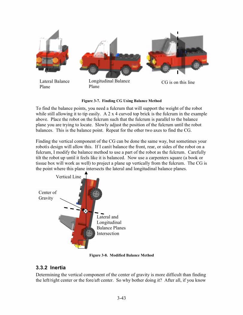
3-43
Figure 3-7. Finding CG Using Balance Method
To find the balance points, you need a fulcrum that will support the weight of the robotwhile still allowing it to tip easily. A 2 x 4 curved top brick is the fulcrum in the exampleabove. Place the robot on the fulcrum such that the fulcrum is parallel to the balanceplane you are trying to locate. Slowly adjust the position of the fulcrum until the robotbalances. This is the balance point. Repeat for the other two axes to find the CG.
Finding the vertical component of the CG can be done the same way, but sometimes yourrobotís design will allow this. If I canít balance the front, rear, or sides of the robot on afulcrum, I modify the balance method to use a part of the robot as the fulcrum. Carefullytilt the robot up until it feels like it is balanced. Now use a carpenters square (a book ortissue box will work as well) to project a plane up vertically from the fulcrum. The CG isthe point where this plane intersects the lateral and longitudinal balance planes.
Figure 3-8. Modified Balance Method
3.3.2 InertiaDetermining the vertical component of the center of gravity is more difficult than findingthe left/right center or the fore/aft center. So why bother doing it? After all, if you know
Longitudinal BalancePlane
CG is on this lineLateral BalancePlane
Center ofGravity
Lateral andLongitudinalBalance PlanesIntersection
Vertical Line
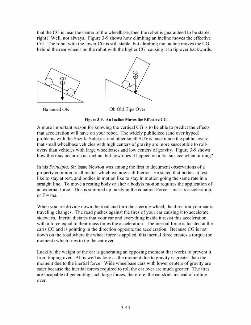
3-44
that the CG is near the center of the wheelbase, then the robot is guaranteed to be stable,right? Well, not always. Figure 3-9 shows how climbing an incline moves the effectiveCG. The robot with the lower CG is still stable, but climbing the incline moves the CGbehind the rear wheels on the robot with the higher CG, causing it to tip over backwards.
Figure 3-9. An Incline Moves the Effective CG
A more important reason for knowing the vertical CG is to be able to predict the effectsthat acceleration will have on your robot. The widely publicized (and over hyped)problems with the Suzuki Sidekick and other small SUVís have made the public awarethat small wheelbase vehicles with high centers of gravity are more susceptible to roll-overs than vehicles with large wheelbases and low centers of gravity. Figure 3-9 showshow this may occur on an incline, but how does it happen on a flat surface when turning?
In his Principia, Sir Isaac Newton was among the first to document observations of aproperty common to all matter which we now call Inertia. He stated that bodies at restlike to stay at rest, and bodies in motion like to stay in motion going the same rate in astraight line. To move a resting body or alter a bodyís motion requires the application ofan external force. This is summed up nicely in the equation Force = mass x acceleration,or F = ma.
When you are driving down the road and turn the steering wheel, the direction your car istraveling changes. The road pushes against the tires of your car causing it to acceleratesideways. Inertia dictates that your car and everything inside it resist this accelerationwith a force equal to their mass times the acceleration. The inertial force is located at thecarís CG and is pointing in the direction opposite the acceleration. Because CG is notdown on the road where the wheel force is applied, this inertial force creates a torque (ormoment) which tries to tip the car over.
Luckily, the weight of the car is generating an opposing moment that works to prevent itfrom tipping over. All is well as long as the moment due to gravity is greater than themoment due to the inertial force. Wide wheelbase cars with lower centers of gravity aresafer because the inertial forces required to roll the car over are much greater. The tiresare incapable of generating such large forces, therefore, the car skids instead of rollingover.
CG
CG
Balanced OK Oh Oh! Tips Over
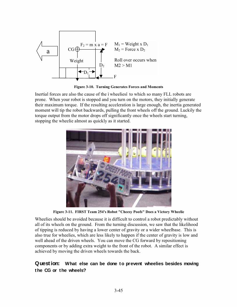
3-45
Figure 3-10. Turning Generates Forces and Moments
Inertial forces are also the cause of the ì wheeliesî to which so many FLL robots areprone. When your robot is stopped and you turn on the motors, they initially generatetheir maximum torque. If the resulting acceleration is large enough, the inertia generatedmoment will tip the robot backwards, pulling the front wheels off the ground. Luckily thetorque output from the motor drops off significantly once the wheels start turning,stopping the wheelie almost as quickly as it started.
Figure 3-11. FIRST Team 254's Robot "Cheesy Poofs" Does a Victory Wheelie
Wheelies should be avoided because it is difficult to control a robot predictably withoutall of its wheels on the ground. From the turning discussion, we saw that the likelihoodof tipping is reduced by having a lower center of gravity or a wider wheelbase. This isalso true for wheelies, which are less likely to happen if the center of gravity is low andwell ahead of the driven wheels. You can move the CG forward by repositioningcomponents or by adding extra weight to the front of the robot. A similar effect isachieved by moving the driven wheels towards the back.
Question: What else can be done to prevent wheelies besides moving
the CG or the wheels?
a
WeightD2
CGF2 = m x a = F
F
M1 = Weight x D1M2 = Force x D2
Roll over occurs whenM2 > M1
D1

3-46
3.4 Wheel Loading and FrictionThe weight of the RCX brick, batteries, three motors, a light sensor, and a rotation sensoris close to 1 pound. Add to this a frame, motor supports, gears, and some sort ofmanipulator, and a typical FLL robot (if there is such a thing) is supporting 1.5 to 2pounds on its wheels. Depending on the relative placement of the wheels and supportingframe components, the force on the axles may be many times greater. These high forcescan cause much of the motor power to be wasted trying to overcome the resultingfriction. What is generating these forces, and how can they be minimized?
Figure 3-12. Cantilevered and Fully Supported Wheels
Most wheeled vehicles use some sort of cantilevered assembly to attach the wheels to thevehicle. Supported on only one side, the axle acts like a lever, generating a moment thathas to be reacted to by the frame. A moment is the product of a force (the weight beingcarried by the wheel) and its perpendicular distance from its axis (the place where theaxle is supported by the frame). The farther the wheel is from the frame, the larger themoment.
The way that the frame reacts the moment has a great effect on the amount of friction.Where the axle passes through the frame it does not rest against the top of the channel,but instead it is tilted, contacting the frame at only two points. The farther apart the twocontact points are, the lower the forces exerted against each.
Figure 3-13. Wheel Loading
Distance a Distance b Force A Force B Friction Forces1 stud 2.5 studs 2.5 W -3.5 W 6 W1 stud 1.5 studs 1.5 W -2.5 W 4 W4 studs 1.5 studs 0.375 W -1.375 W 1.75 W
W
A A A
B B B
aa ab b b
W W
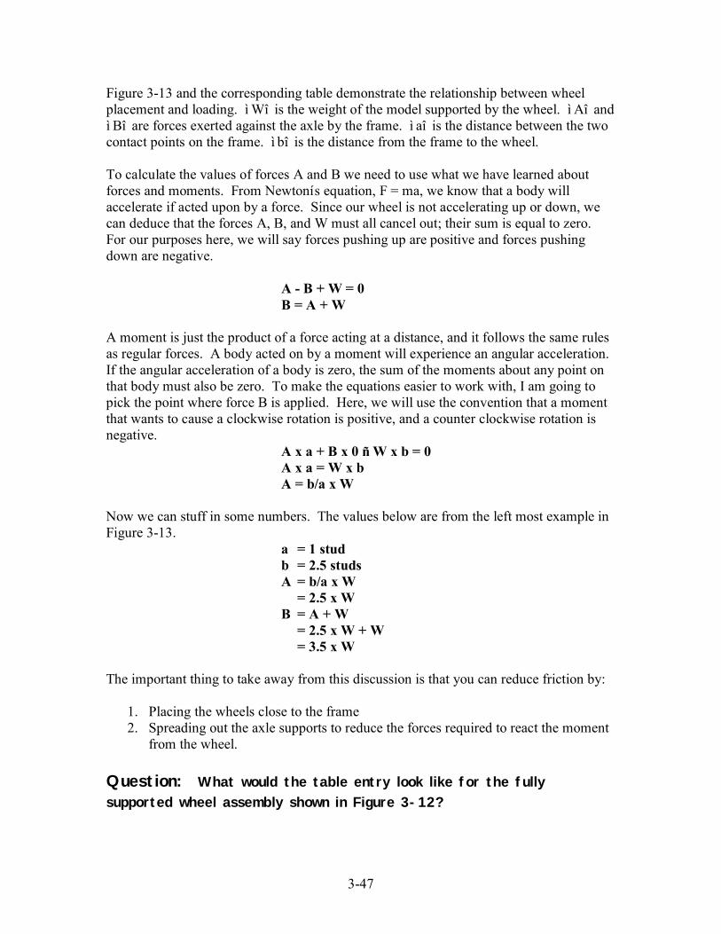
3-47
Figure 3-13 and the corresponding table demonstrate the relationship between wheelplacement and loading. ìWî is the weight of the model supported by the wheel. ì Aî andì Bî are forces exerted against the axle by the frame. ì aî is the distance between the twocontact points on the frame. ì bî is the distance from the frame to the wheel.
To calculate the values of forces A and B we need to use what we have learned aboutforces and moments. From Newtonís equation, F = ma, we know that a body willaccelerate if acted upon by a force. Since our wheel is not accelerating up or down, wecan deduce that the forces A, B, and W must all cancel out; their sum is equal to zero.For our purposes here, we will say forces pushing up are positive and forces pushingdown are negative.
A - B + W = 0B = A + W
A moment is just the product of a force acting at a distance, and it follows the same rulesas regular forces. A body acted on by a moment will experience an angular acceleration.If the angular acceleration of a body is zero, the sum of the moments about any point onthat body must also be zero. To make the equations easier to work with, I am going topick the point where force B is applied. Here, we will use the convention that a momentthat wants to cause a clockwise rotation is positive, and a counter clockwise rotation isnegative.
A x a + B x 0 ñ W x b = 0A x a = W x bA = b/a x W
Now we can stuff in some numbers. The values below are from the left most example inFigure 3-13.
a = 1 studb = 2.5 studsA = b/a x W= 2.5 x W
B = A + W= 2.5 x W + W= 3.5 x W
The important thing to take away from this discussion is that you can reduce friction by:
1. Placing the wheels close to the frame2. Spreading out the axle supports to reduce the forces required to react the momentfrom the wheel.
Question: What would the table entry look like for the fully
supported wheel assembly shown in Figure 3-12?

4-48
4 Lego Electronics
4.1 RCX BrickThe RCX is your robotís brain, a tiny computer shaped like a LEGO brick. At the core ofthe RCX is a Hitachi H8 8 bit microcontroller running at 5 to 20 MHz with 32K of RAM.This may seem anemic when compared to modern desktop computers with 2GHz 32 bitprocessors and 512 Mbytes of memory, but itís as powerful as the Apple II computer Ilearned to program on and significantly more powerful than the computers that sent mento the moon.
The microcontroller is used to control three voltage outputs, three sensor inputs, and aninfrared serial communications port. Snap-on wire leads are used to connect the RCX tomotors, lamps, touch sensors, light sensors, rotation sensors, etcÖ The serialcommunication port is used to download programs from a PC and can be used tocommunicate between two RCXís.
The RCX is powered by 6 AA batteries. Older versions of the RCX also had a 9V DCinput plug for use with an optional AC adapter. If you have this model of RCX, thetransformer will pay for itself in saved battery costs. Having two or three sets of goodquality rechargeable batteries is also a good idea. The rechargeable alkaline batteriesseem to work best with the RCX.
Construction Note: When building your robot, remember that you will haveto occasionally remove the RCX to replace the batteries. Design accordingly.
Figure 4-1. The RCX Programmable Brick
4.1.1 Firmware
The RCX contains 32K of battery-backed RAM. Most of this is used up by the firmwarethat you have to install prior to loading your own robot programs. An additional 6K isreserved to store up to five user programs. This may not seem like much space, but most
4-49
RCX programs are only a few hundred bytes long. The remaining memory is used forrunning programs.
When a program is written for the RCX, it does not contain native code for the CPU.Instead, it is made up of special bytecodes which are interpreted by the firmware. This issimilar to the way Java programs on the web are interpreted by the Java Virtual Machinerunning in your browser. Using a bytecode interpreter allows the RCX to maintain areliable environment for executing user programs. Your program may not do what youwant, but it wonít crash the RCX.
Because the firmware is stored in RAM, it is erased if your RCX remains without powerfor more than a few seconds. A capacitor in the RCX powers the memory long enoughfor you to change the batteries (15-30 seconds). If after changing batteries your RCX nolonger functions properly, you may have lost your firmware. You can tell if the firmwareis loaded by looking at the LCD display. If all you can see is the program number andthe minifig icon (either standing or walking as in Figure 4-1), then the firmware is notloaded. This will be the condition of your RCX brick when you receive your kit.
Construction Note: Whenever it is turned on, the RCX is receptive tomessages coming in on its infrared serial port. With all the activity and
congestion at competitions, it is quite possible that another team couldunintentionally overwrite the programs stored in your RCX. Care should betaken to block the IR port when not in use.
4.1.2 Programming
The RCX is programmed using special software that resides on your PC. The program istranslated into bytecodes and transferred to the RCX via an infrared serial link (using theIR tower). This method of programming--writing code on one type of computer to be runon another type of computer--is called cross development. A computer without akeyboard and monitor, like the RCX, is called an embedded system. That means allFLLíers are embedded systems developers, familiar with cross development tools. Thisis impressive stuff to put on your resume.
User programs can be written either in RCX Code or ROBOLAB. RCX Code is thegraphical programming tool that LEGO supplies to program the RCX. It is targeted topeople with no programming experience. Programs are written by picking instructionblocks and snapping them together, much like using actual LEGO bricks. The originalversions of RCX Code were very limited (V1.0 and V1.5). Many instructions supportedby the bytecode interpreter were not available, and support for variables was minimal. Ifyou plan to use RCX Code, make sure you have the version 2.0 software. RCX Code iscurrently only available for Windows PCís.

4-50
Figure 4-2. RCX Code Screenshot
ROBOLAB is a product of LEGO DACTA, the education branch of LEGO. It is basedon LabVIEW, a graphical programming environment that is really used by engineers andscientists for measurement and control. In fact, NASA scientists used LabVIEW tomonitor the Sojourner Rover on Mars! Like RCX Code, ROBOLAB uses a graphicalmetaphor for writing programs. Command icons are selected from a palette and placed inthe programming workspace. Then the command icons are wired together to specify theprogram flow.
Figure 4-3. ROBOLAB Screenshot
ROBOLAB is a more powerful tool than RCX Code, but not all this power is directedtowards programming robots. Large portions of ROBOLAB are devoted to using theRCX like a lab instrument. You can create programs that run on the PC but collectsensor data from the RCX. Other ROBOLAB tools are available to process and analyzethe data. There are even tools for publishing the results or converting them to a web

4-51
page. Learning all there is to ROBOLAB could take a long time. Luckily, everything youneed for FLL is isolated in one section called Inventor. ROBOLAB also has extensiveuser documentation built into the tool, plus there is a very thorough user manual availableonline at http://www.ceeo.tufts.edu/robolabatceeo/documentation.htm .
Programming using RCX Code or ROBOLAB is pretty much the same. The programmeruses the mouse to select from a list of icons that represent program instructions. Theselected instruction icons are placed into a workspace. Some sort of graphical connectionmetaphor is used to define the flow of the program (snapping together for RCX Code,wires for ROBOLAB). When the programmer finishes laying out the instructions, he/sheuses a menu or toolbar button to compile the program and download it to the RCX.
If you are programming on a Mac, then you have to use ROBOLAB. Otherwise, thechoice is mostly a matter of taste. Careful analysis of Minnesota FLL competition resultsover the last three seasons shows no correlation between a teamís success and theprogramming language it used.
4.2 MotorsThe motor that comes with the challenge kit is called the 9 volt geared motor. It has aninternal gear train that delivers a 12:1 gear reduction. This converts an internal rotationspeed of 4200 rpm to a more useable 350 rpm5 at the output shaft. The internal gearingalso increases the stall torque to 8.9 Ncm or 0.06 ft-lbs6.
Figure 4-4. 9 Volt Geared Motor
The motor normally draws about 10 milliamps (mA) of current under no load. This caneasily increase to 200 mA or more when it is working hard. Add powered sensors (lightand rotation), the LCD display, the processor, and a typical FLL robot can be drawing600 ñ 700 milliamps. Since good quality AA batteries are rated around 2500 milliamphours (mAh) you can expect to change batteries after three to four hours of operation.
5 Typical speed under load is closer to 200 rpm6 From the Random Hall Lego Robotics Seminar (web.min.edu/sp.742/www/motor.html)
4 Studs
3.6 Studs or3 Bricks
2.8 Studs or2.33 Bricks
4 Studs
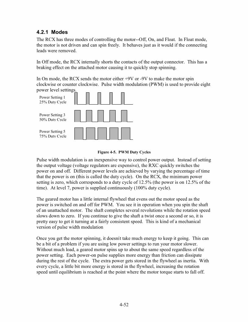
4-52
4.2.1 ModesThe RCX has three modes of controlling the motor--Off, On, and Float. In Float mode,the motor is not driven and can spin freely. It behaves just as it would if the connectingleads were removed.
In Off mode, the RCX internally shorts the contacts of the output connector. This has abraking effect on the attached motor causing it to quickly stop spinning.
In On mode, the RCX sends the motor either +9V or -9V to make the motor spinclockwise or counter clockwise. Pulse width modulation (PWM) is used to provide eightpower level settings.
Figure 4-5. PWM Duty Cycles
Pulse width modulation is an inexpensive way to control power output. Instead of settingthe output voltage (voltage regulators are expensive), the RXC quickly switches thepower on and off. Different power levels are achieved by varying the percentage of timethat the power is on (this is called the duty cycle). On the RCX, the minimum powersetting is zero, which corresponds to a duty cycle of 12.5% (the power is on 12.5% of thetime). At level 7, power is supplied continuously (100% duty cycle).
The geared motor has a little internal flywheel that evens out the motor speed as thepower is switched on and off for PWM. You see it in operation when you spin the shaftof an unattached motor. The shaft completes several revolutions while the rotation speedslows down to zero. If you continue to give the shaft a twist once a second or so, it ispretty easy to get it turning at a fairly consistent speed. This is kind of a mechanicalversion of pulse width modulation
Once you get the motor spinning, it doesnít take much energy to keep it going. This canbe a bit of a problem if you are using low power settings to run your motor slower.Without much load, a geared motor spins up to about the same speed regardless of thepower setting. Each power-on pulse supplies more energy than friction can dissipateduring the rest of the cycle. The extra power gets stored in the flywheel as inertia. Withevery cycle, a little bit more energy is stored in the flywheel, increasing the rotationspeed until equilibrium is reached at the point where the motor torque starts to fall off.
Power Setting 575% Duty Cycle
Power Setting 125% Duty Cycle
Power Setting 350% Duty Cycle
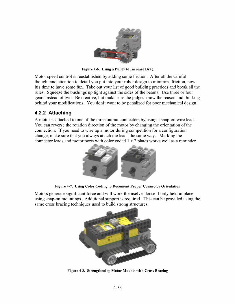
4-53
Figure 4-6. Using a Pulley to Increase Drag
Motor speed control is reestablished by adding some friction. After all the carefulthought and attention to detail you put into your robot design to minimize friction, nowitís time to have some fun. Take out your list of good building practices and break all therules. Squeeze the bushings up tight against the sides of the beams. Use three or fourgears instead of two. Be creative, but make sure the judges know the reason and thinkingbehind your modifications. You donít want to be penalized for poor mechanical design.
4.2.2 AttachingA motor is attached to one of the three output connectors by using a snap-on wire lead.You can reverse the rotation direction of the motor by changing the orientation of theconnection. If you need to wire up a motor during competition for a configurationchange, make sure that you always attach the leads the same way. Marking theconnector leads and motor ports with color coded 1 x 2 plates works well as a reminder.
Figure 4-7. Using Color Coding to Document Proper Connector Orientation
Motors generate significant force and will work themselves loose if only held in placeusing snap-on mountings. Additional support is required. This can be provided using thesame cross bracing techniques used to build strong structures.
Figure 4-8. Strengthening Motor Mounts with Cross Bracing
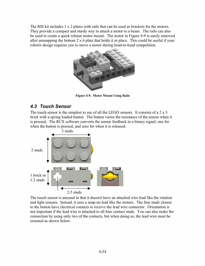
4-54
The RIS kit includes 1 x 2 plates with rails that can be used as brackets for the motors.They provide a compact and sturdy way to attach a motor to a beam. The rails can alsobe used to create a quick release motor mount. The motor in Figure 4-9 is easily removedafter unsnapping the bottom 2 x 6 plate that holds it in place. This could be useful if yourrobotís design requires you to move a motor during head-to-head competition.
Figure 4-9. Motor Mount Using Rails
4.3 Touch SensorThe touch sensor is the simplest to use of all the LEGO sensors. It consists of a 2 x 3brick with a spring loaded button. The button varies the resistance of the sensor when itis pressed. The RCX software converts the sensor feedback to a binary signal: one forwhen the button is pressed, and zero for when it is released.
The touch sensor is unusual in that it doesnít have an attached wire lead like the rotationand light sensors. Instead, it uses a snap-on lead like the motors. The four studs closestto the button have electrical contacts to receive the lead wire connector. Orientation isnot important if the lead wire is attached to all four contact studs. You can also make theconnection by using only two of the contacts, but when doing so, the lead wire must beoriented as shown below.
2 studs
3 studs
1 brick or1.2 studs
2.5 studs

4-55
Figure 4-10. Wiring the Touch Sensor
4.3.1 BumpersA bumper is a device that notifies your robot that you ran into an obstacle. When struck,the bumper moves and presses or releases a touch sensor, notifying your robot of theimpact. Bumpers are the most common use for a touch sensor in FLL. This may be dueto the Constructopedia using touch sensors primarily in this role, or it could be becausebumpers are such useful devices.
Figure 4-11. A Simple Bumper
A bumper assembly usually consists of four parts: the bumper, a sensor, a returnmechanism, and a supporting framework. The bumper component is the part thatreceives the impact and converts it to motion that can be detected by the sensor. Themotion is usually sliding (Figure 4-11) or pivoting (Figure 4-12), though I have seensome interesting bumpers built of flexible parts that use bending. The sensor componentis usually a touch sensor, but bumpers can be built using rotation sensors or light sensors.
Figure 4-12. A Bumper that Uses the Rotation Sensor
Good Bad

4-56
The return mechanism forces the bumper to its normal (non-impacted) state when theobstacle is removed. The most common return mechanism is a rubber band that pulls thebumper against a mechanical stop. The design of some bumpers allows gravity to beused as the return mechanism. The simple bumper in Figure 4-11 originally used thespring inside the touch sensor as the return mechanism. That design proved to beunreliable, occasionally signaling a collision when none had occurred. Adding the rubberband fixed the problem.
Figure 4-13. A Normally Closed Bumper Design
Most bumper designs can be divided into two categories based on the way they monitortheir sensor for impacts. The bumper in Figure 4-11 is a ì Normally Openî design. Whena collision occurs, the bumper presses against the touch sensor, closing the contacts. In aì Normally Closedî style of bumper, the return mechanism pulls the bumper against thetouch sensor. A collision causes the bumper to pull away from the touch sensor, openingthe contacts.
When the normally open bumper in Figure 4-11 collides with an obstacle, the impact ofthe collision is transmitted through the bumper to the touch sensor. This will loosen thesensor mounting, and after a few collisions the sensor may fall off. Additional bracingcould be used to strengthen the sensor mounting, but this just transmits the impact to therobot frame.
In a normally closed bumper like that in Figure 4-13, the force of a collision is absorbedby the rubber bands. This bumper also has a long ì throw,î the distance between where acollision is detected and the bumper ì bottoms outî against a hard stop. The long throwallows the bumper to sense an obstacle and stop the robot before a hard collision occurs.
Figure 4-14. Improved Normally Open Bumper

4-57
Normally closed bumpers are good at detecting obstacles and protecting your robot fromforceful collisions. But the normally closed touch sensor causes problems for sensorstacking (attaching multiple sensors to one input port). A closed touch sensor will forcethe input to be 1 (if configured as a touch sensor port) or 100 (if configured as a lightsensor port). The improved bumper above retains all the benefits of a normally closeddesign with the advantage of having the touch sensor be normally open.
4.3.2 Limit and Position SwitchesTouch sensors have many uses other than bumpers. Limit and position switches tell youwhen a component of your robot is in a certain location. They are discrete sensors (asopposed to continuous sensors) in that they provide position information only at certainlocations. You only know where you are while the touch sensor is pressed. When it isopen, you only know where you are not.
Figure 4-15. Position and Limit Switches
Limit and position switches really differ only in their use. Limit switches are guards thatwatch for something being where it is not supposed to be. They are protectivemechanisms used when damage could result from a device moving outside its workingenvelope. A position switch is just the opposite; it is a messenger that notifies you whena device is where you want it to be.
The light scanner in Figure 4-15 has two limit switches and a position switch, and all useonly one touch sensor! The bottom two cams are part of the limit switches. They preventthe scanner post from twisting more than +/-90 degrees. The top cam is a position switchthat tells the RCX when the sensor is pointed straight forward. To be able to interpret thetouch sensor feedback, the program has to keep careful track of where the scanner post isand which way it is spinning.
4.3.3 Rotation sensorPerhaps the most repeated gripe Iíve heard from FLL teams is about the lack of a secondrotation sensor. Having two just seems to make sense: one for left and one for right, orone for distance and one for steering. Other teams see the lack of a second rotationsensor as a challenge, and some of their solutions have been very creative.

4-58
Figure 4-16. A Touch Rotation Sensor
Just as a rotation sensor can be used in place of a touch sensor as part of a bumper, atouch sensor can be used to measure rotation. In the rotation sensor, opto-interrupters uselight to monitor the position of a fan-shaped rotor. In Figure 4-17, the touch sensor isused to monitor the position of the axle joiner.
Question: What is the resolution of the rotation sensor in Figure
4-16?
4.4 Light SensorThe light sensor is a 2 x 4 LEGO brick that contains a red light emitting diode (LED) anda photo transistor. The red LED illuminates the area in front of the brick, and the phototransistor measures the intensity of the reflected light. The light sensor returns a value inthe range of 0 to 100%. The lowest reading I have ever seen is 20%, which I took atmidnight in the middle of my basement with the lights off. You can get to 100% byaiming the sensor at the sun on a clear day or by holding it within a few inches of a 100Wlight bulb. In normal operation, the sensor values tend to be between 30 and 60%.
Figure 4-17. The Light Sensor
One of my earliest experiences with the light sensor was when I used it as part of a candysorter. I wanted to sort bags of peanut M&Ms based on the color of their candy shells(brown is my favorite). The concept was simple. I would use the light to determine thecolor, then move the robot to position it over the correct bin.
2 studs
4 studs
1.33 bricksor1.6 studs
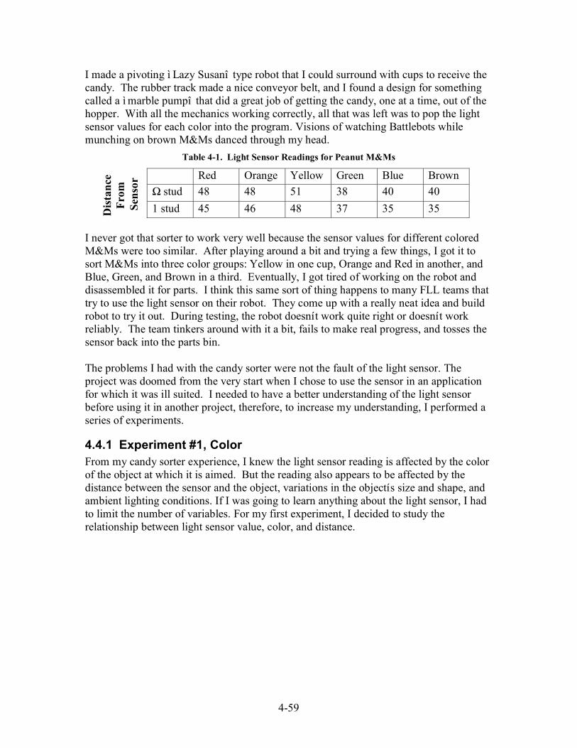
4-59
I made a pivoting ì Lazy Susanî type robot that I could surround with cups to receive thecandy. The rubber track made a nice conveyor belt, and I found a design for somethingcalled a ì marble pumpî that did a great job of getting the candy, one at a time, out of thehopper. With all the mechanics working correctly, all that was left was to pop the lightsensor values for each color into the program. Visions of watching Battlebots whilemunching on brown M&Ms danced through my head.
Table 4-1. Light Sensor Readings for Peanut M&Ms
Red Orange Yellow Green Blue Brown
Ω stud 48 48 51 38 40 40
1 stud 45 46 48 37 35 35
I never got that sorter to work very well because the sensor values for different coloredM&Ms were too similar. After playing around a bit and trying a few things, I got it tosort M&Ms into three color groups: Yellow in one cup, Orange and Red in another, andBlue, Green, and Brown in a third. Eventually, I got tired of working on the robot anddisassembled it for parts. I think this same sort of thing happens to many FLL teams thattry to use the light sensor on their robot. They come up with a really neat idea and buildrobot to try it out. During testing, the robot doesnít work quite right or doesnít workreliably. The team tinkers around with it a bit, fails to make real progress, and tosses thesensor back into the parts bin.
The problems I had with the candy sorter were not the fault of the light sensor. Theproject was doomed from the very start when I chose to use the sensor in an applicationfor which it was ill suited. I needed to have a better understanding of the light sensorbefore using it in another project, therefore, to increase my understanding, I performed aseries of experiments.
4.4.1 Experiment #1, ColorFrom my candy sorter experience, I knew the light sensor reading is affected by the colorof the object at which it is aimed. But the reading also appears to be affected by thedistance between the sensor and the object, variations in the objectís size and shape, andambient lighting conditions. If I was going to learn anything about the light sensor, I hadto limit the number of variables. For my first experiment, I decided to study therelationship between light sensor value, color, and distance.
Distance
From
Sensor

4-60
Figure 4-18. Light Sensor Color Experiment
For this experiment, I built a box out of LEGO parts with a light sensor centered at oneend. The box had solid sides and a top and bottom to prevent ambient light fromdistorting the results. Next, I made several different colored ì targetsî that I could placein the box at various distances from the sensor. I used 1 x 4 bricks to make the targetsbecause I have them in many different colors, and they will allow others to easilyreproduce my work. For each different color, I took sensor readings at 1, 2, 3, 4, and 5studs spacing. The results are shown in the table below.
Table 4-2. Light Sensor Readings for Color Experiment
Distance (studs)1 2 3 4 5
Black 43 38 35 33 27
White 54 48 43 40 37
Gray 49 43 39 35 32
Dk Gray 45 40 35 31 29
Yellow 53 48 43 39 36
Red 50 45 41 37 35
Blue 44 38 34 32 31
Green 42 37 32 29 28
4.4.1.1 ColorAs I was performing my light sensor experiments, it became apparent that the light sensordoesnít see light the same way I do. To my eyes, the green bricks appear brighter thanthe red bricks, yet the green brick sensor readings were consistently lower. In fact, thelight sensor readings for the green, blue, dark gray, and black bricks were essentially thesame.
Light is made up of electromagnetic waves--vibrations of electric and magnetic fields thattravel through space. There are many types of electromagnetic waves: some we can feel(heat), some we can see (light), and some we have harnessed for our own uses (televisionand radio). Our eyes can detect electromagnetic waves with wavelengths in the range of400nm (violet) to 700nm (red) in length. We call this tiny portion of the electromagneticspectrum visible light. Our eyes perceive different wavelengths of visible light as having
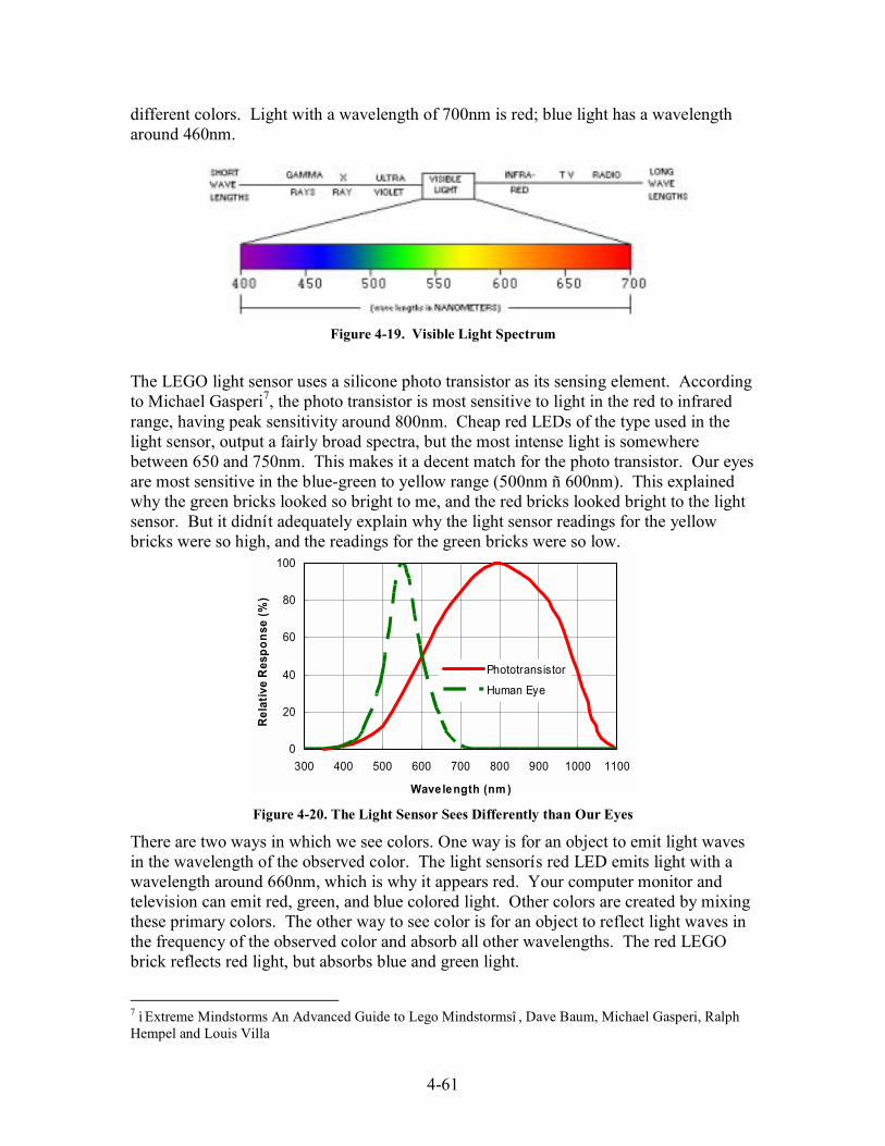
4-61
different colors. Light with a wavelength of 700nm is red; blue light has a wavelengtharound 460nm.
Figure 4-19. Visible Light Spectrum
The LEGO light sensor uses a silicone photo transistor as its sensing element. Accordingto Michael Gasperi7, the photo transistor is most sensitive to light in the red to infraredrange, having peak sensitivity around 800nm. Cheap red LEDs of the type used in thelight sensor, output a fairly broad spectra, but the most intense light is somewherebetween 650 and 750nm. This makes it a decent match for the photo transistor. Our eyesare most sensitive in the blue-green to yellow range (500nm ñ 600nm). This explainedwhy the green bricks looked so bright to me, and the red bricks looked bright to the lightsensor. But it didnít adequately explain why the light sensor readings for the yellowbricks were so high, and the readings for the green bricks were so low.
0
20
40
60
80
100
300 400 500 600 700 800 900 1000 1100
Wavelength (nm )
Relative Response (%)
Phototransistor
Human Eye
Figure 4-20. The Light Sensor Sees Differently than Our Eyes
There are two ways in which we see colors. One way is for an object to emit light wavesin the wavelength of the observed color. The light sensorís red LED emits light with awavelength around 660nm, which is why it appears red. Your computer monitor andtelevision can emit red, green, and blue colored light. Other colors are created by mixingthese primary colors. The other way to see color is for an object to reflect light waves inthe frequency of the observed color and absorb all other wavelengths. The red LEGObrick reflects red light, but absorbs blue and green light.
7 ì Extreme Mindstorms An Advanced Guide to Lego Mindstormsî , Dave Baum, Michael Gasperi, RalphHempel and Louis Villa

4-62
Figure 4-21. Light Colors
The light sensor readings in Table 4-2 start to make sense when you think of color interms of emission, reflection, and absorption. With the cover placed on my test box, theonly light striking the colored brick target was the red light emitted from the red LED.The red LEGO bricks are very good at reflecting red light, thatís why they appear red tous and bright to the sensor. The green and blue bricks donít reflect red light well at alland have sensor readings that would make you think they were black. The yellow andwhite bricks give the highest sensor readings because they reflect red light and otherwavelengths the LED emits as well.
Question: In a dark room, what color do you see when shining the
light sensor’s red LED light on a yellow LEGO brick?
4.4.1.2 DistanceThe Inverse Square Law is a neat mathematical formula that shows up all over the placein physics. It defines the relationship between the measured strength of a thing, like thepull of gravity or the loudness of sound, and the distance you are from the source of thething. The Inverse Square Law for light intensity states that the intensity of lightobserved from a source of constant brightness falls off as a square of the distance fromthe object. It is generally expressed as the ratio of light intensities l1 and l2 at distances d1and d2.
21
22
2
1
d
d
l
l =
0
20
40
60
80
100
1 2 3 4 5
Relative Distance
Relative Intensity (%)
This means that if we double the distance to a light source, the observed intensity isdecreased to (1/2)
2 or º of its original value. At 3, 4, and 5 times the distance, the
White
Green
Blue
Red
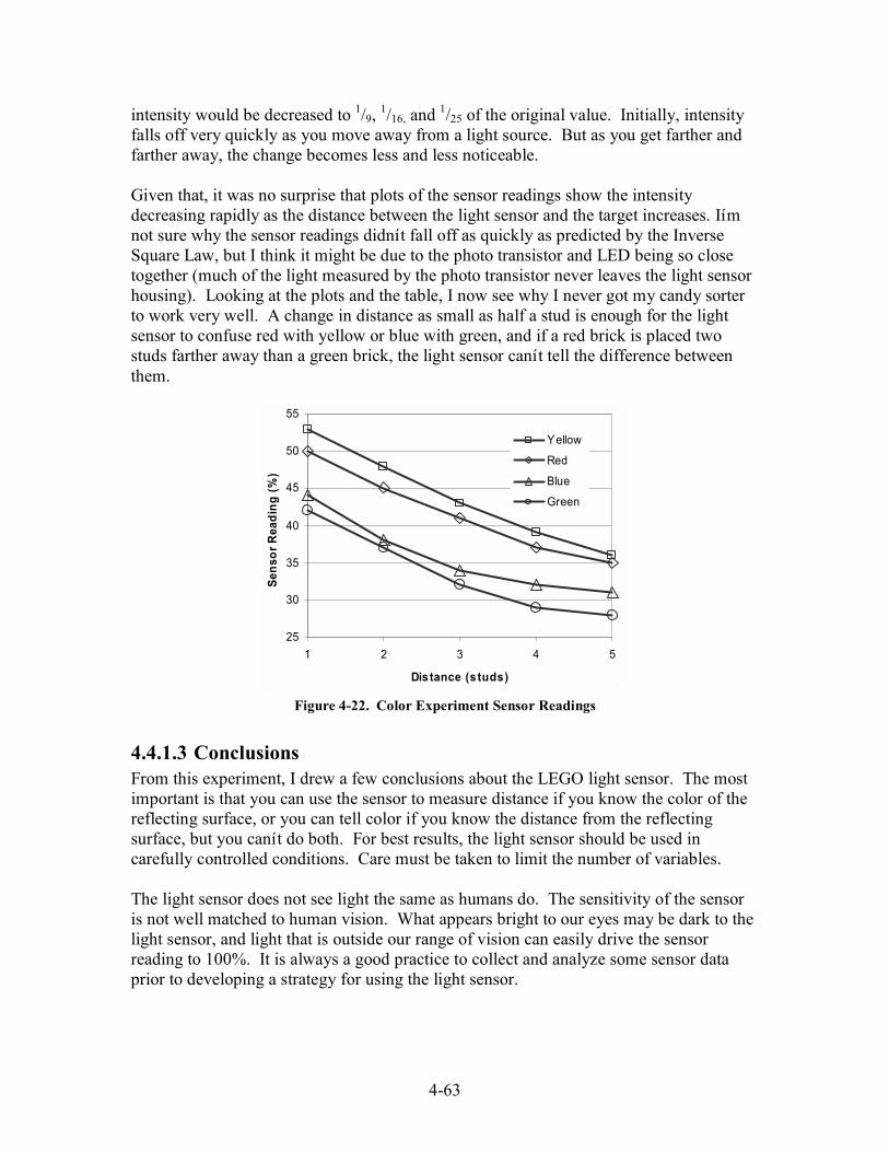
4-63
intensity would be decreased to 1/9, 1/16, and
1/25 of the original value. Initially, intensityfalls off very quickly as you move away from a light source. But as you get farther andfarther away, the change becomes less and less noticeable.
Given that, it was no surprise that plots of the sensor readings show the intensitydecreasing rapidly as the distance between the light sensor and the target increases. Iímnot sure why the sensor readings didnít fall off as quickly as predicted by the InverseSquare Law, but I think it might be due to the photo transistor and LED being so closetogether (much of the light measured by the photo transistor never leaves the light sensorhousing). Looking at the plots and the table, I now see why I never got my candy sorterto work very well. A change in distance as small as half a stud is enough for the lightsensor to confuse red with yellow or blue with green, and if a red brick is placed twostuds farther away than a green brick, the light sensor canít tell the difference betweenthem.
25
30
35
40
45
50
55
1 2 3 4 5
Distance (s tuds)
Sensor Reading (%)
Yellow
Red
Blue
Green
Figure 4-22. Color Experiment Sensor Readings
4.4.1.3 ConclusionsFrom this experiment, I drew a few conclusions about the LEGO light sensor. The mostimportant is that you can use the sensor to measure distance if you know the color of thereflecting surface, or you can tell color if you know the distance from the reflectingsurface, but you canít do both. For best results, the light sensor should be used incarefully controlled conditions. Care must be taken to limit the number of variables.
The light sensor does not see light the same as humans do. The sensitivity of the sensoris not well matched to human vision. What appears bright to our eyes may be dark to thelight sensor, and light that is outside our range of vision can easily drive the sensorreading to 100%. It is always a good practice to collect and analyze some sensor dataprior to developing a strategy for using the light sensor.

4-64
I also learned that the light sensor is extremely sensitive to the distance between thesensor and the reflecting surface. When using the sensor to measure contrast it must beheld a fixed distance from the reflecting surface. Even small variations in distance canmake the sensor readings unusable. Remember this when designing the light sensormount for your robot.
4.4.2 Experiment #2, Ambient LightIn my first experiment, I studied the relationship between color and the light sensorreading. From the data, I deduced that the sensor reading is not only dependant upon thecolor of the object being viewed but also upon the wavelength of the light illuminatingthe object. In normal usage, the light sensor and target will not be in a sealed container.Light from external sources, ambient light, will have some effect on the sensor reading.To better understand how ambient light affects the sensor readings, I performed a secondexperiment.
For this experiment, I built a wall of different colored bricks to use as a target and anadjustable stand to hold the sensor a known distance away from the bricks. The standwas ì spider likeî to minimize the shadow it cast. I then recorded the light sensorreadings for each colored brick at different distances under a variety of lightingconditions. First, as a baseline, I took measurements in a completely dark room in mybasement (light sensor reading 22%). I repeated the experiment in ì normal basementîlighting conditions (sensor reading 46%) and then in ì bright competitionî lightingconditions (sensor reading 65%). The readings appear in Table 4-3.
Figure 4-23. Ambient Light Experiment
The first thing I noticed from the data was how the green and blue sensor readings werethe most affected by the presence of ambient light. The incandescent lamps used toproduce the moderate and bright lighting conditions emit a full spectrum of visible lightwavelengths. This gives the blue and green bricks something to reflect, so they appearmuch brighter to the sensor than in the previous experiment.
Question: In the ’01 FLL challenge “Volcano Panic,” a blue tape line
was used to mark the edge of the ocean. The intersection of the blue
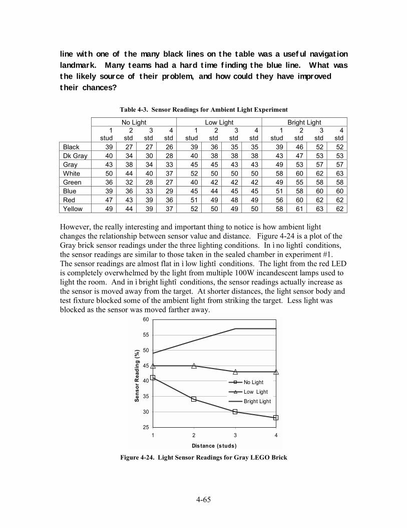
4-65
line with one of the many black lines on the table was a useful navigation
landmark. Many teams had a hard time finding the blue line. What wasthe likely source of their problem, and how could they have improved
their chances?
Table 4-3. Sensor Readings for Ambient Light Experiment
No Light Low Light Bright Light
1
stud2
std3
std4
std1
stud2
std3
std4
std1
stud2
std3
std4
stdBlack 39 27 27 26 39 36 35 35 39 46 52 52Dk Gray 40 34 30 28 40 38 38 38 43 47 53 53Gray 43 38 34 33 45 45 43 43 49 53 57 57White 50 44 40 37 52 50 50 50 58 60 62 63Green 36 32 28 27 40 42 42 42 49 55 58 58Blue 39 36 33 29 45 44 45 45 51 58 60 60Red 47 43 39 36 51 49 48 49 56 60 62 62Yellow 49 44 39 37 52 50 49 50 58 61 63 62
However, the really interesting and important thing to notice is how ambient lightchanges the relationship between sensor value and distance. Figure 4-24 is a plot of theGray brick sensor readings under the three lighting conditions. In ì no lightî conditions,the sensor readings are similar to those taken in the sealed chamber in experiment #1.The sensor readings are almost flat in ì low lightî conditions. The light from the red LEDis completely overwhelmed by the light from multiple 100W incandescent lamps used tolight the room. And in ì bright lightî conditions, the sensor readings actually increase asthe sensor is moved away from the target. At shorter distances, the light sensor body andtest fixture blocked some of the ambient light from striking the target. Less light wasblocked as the sensor was moved farther away.
25
30
35
40
45
50
55
60
1 2 3 4
Distance (s tuds)
Sensor Reading (%)
No Light
Low Light
Bright Light
Figure 4-24. Light Sensor Readings for Gray LEGO Brick
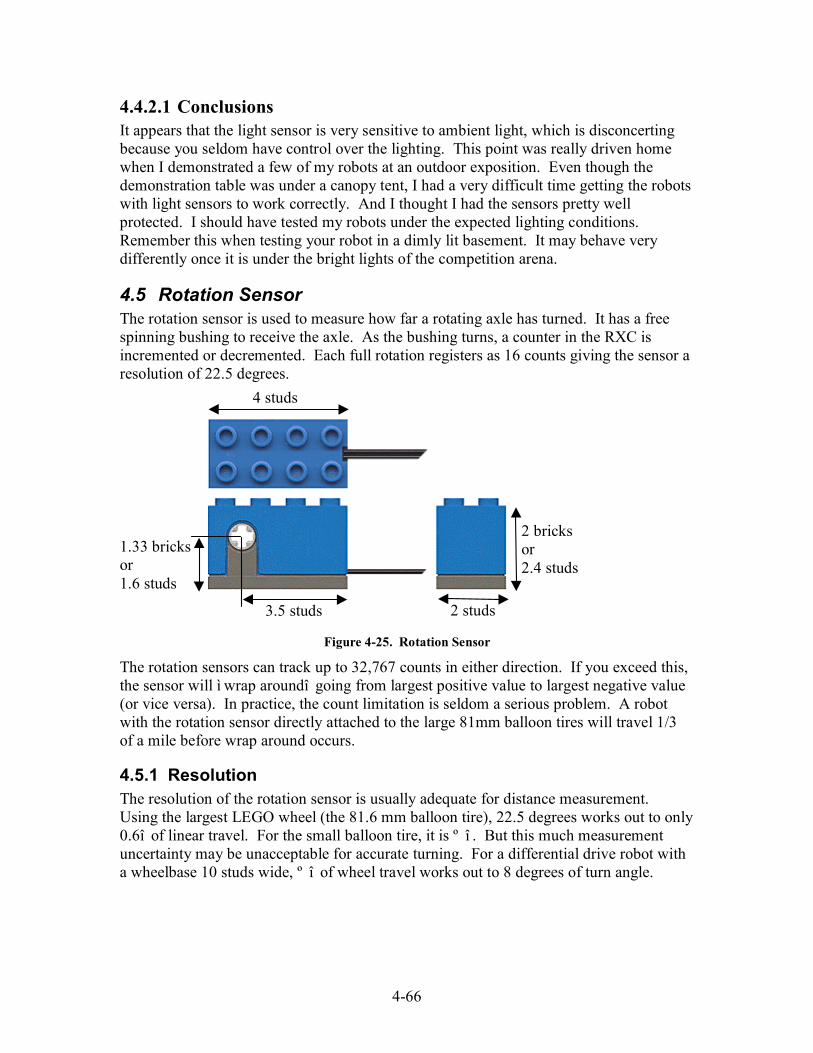
4-66
4.4.2.1 ConclusionsIt appears that the light sensor is very sensitive to ambient light, which is disconcertingbecause you seldom have control over the lighting. This point was really driven homewhen I demonstrated a few of my robots at an outdoor exposition. Even though thedemonstration table was under a canopy tent, I had a very difficult time getting the robotswith light sensors to work correctly. And I thought I had the sensors pretty wellprotected. I should have tested my robots under the expected lighting conditions.Remember this when testing your robot in a dimly lit basement. It may behave verydifferently once it is under the bright lights of the competition arena.
4.5 Rotation SensorThe rotation sensor is used to measure how far a rotating axle has turned. It has a freespinning bushing to receive the axle. As the bushing turns, a counter in the RXC isincremented or decremented. Each full rotation registers as 16 counts giving the sensor aresolution of 22.5 degrees.
Figure 4-25. Rotation Sensor
The rotation sensors can track up to 32,767 counts in either direction. If you exceed this,the sensor will ì wrap aroundî going from largest positive value to largest negative value(or vice versa). In practice, the count limitation is seldom a serious problem. A robotwith the rotation sensor directly attached to the large 81mm balloon tires will travel 1/3of a mile before wrap around occurs.
4.5.1 ResolutionThe resolution of the rotation sensor is usually adequate for distance measurement.Using the largest LEGO wheel (the 81.6 mm balloon tire), 22.5 degrees works out to only0.6î of linear travel. For the small balloon tire, it is º î . But this much measurementuncertainty may be unacceptable for accurate turning. For a differential drive robot witha wheelbase 10 studs wide, º î of wheel travel works out to 8 degrees of turn angle.
2 studs
4 studs
2 bricksor2.4 studs
3.5 studs
1.33 bricksor1.6 studs

4-67
Figure 4-26. Using Gear Reduction to Increase Resolution
Effective sensor resolution can be increased using gear reduction. For the example inFigure 4-26, the input shaft (one with the worm gear) turns 24 times for each revolutionof the output shaft (one with the spur gear). The rotation sensor will generate 384 countsfor each revolution of the 24 tooth gear. Thatís less that 1 degree per count.Unfortunately, this assembly has about 2 degrees of backlash, causing a lot of thatresolution to be wasted.
4.5.2 InternalsThe rotation sensor is an interesting little device. If you had Supermanís X-ray vision,you could see that it is built using two tiny opto-interrupters. These are fork shapeddevices that have an LED on one tine and a photo resistor on the other. The photoresistor senses when an obstruction passes between it and the LED.
Figure 4-27. Rotation Sensor Internals. DON'T DO THIS!!!
The rotating bushing has four little fan blades that pass between the opto-interrupters asthe bushing spins. The opto-interrupter output changes as a blade enters and again as itleaves. This gives 8 transitions per rotation for each sensor. Using two sensors provides16 counts per revolution plus allows the sensor to calculate the direction of rotation..

4-68
Figure 4-28. Homemade Rotation Sensor Made From LEGO Parts
You can use a light sensor, lamp, and medium pulley wheel to build your own rotationsensor. The light sensor and lamp are used to implement the opto-interrupter. As theaxle turns, the pulley wheel will alternately block or transmit light from the lamp. Withonly one sensor, you cannot determine rotation direction, but direction can usually beascertained by looking at the motor commands.
Question: What is the resolution of the homemade rotation sensor in
Figure 4-28?
4.5.3 Counting ErrorsThere have been dozens of posts on LUGNET (LEGO Users Group Network) discussinga mysterious problem with the LEGO rotation sensor. There is a wide held belief thatcounting errors occur if the rotation speed is too fast or too slow. Exact speeds areuncertain, but they have been reported to be below 10-20 rpm or above 1200-1400 rpm.The large body of experimental data available on the web seems to agree that the rotationsensor is quite reliable if speeds are kept in the 60 ñ 1000 rpm range.
Figure 4-29. A Homing Switch to Reset the Rotation Sensor
The rotation sensor can be tricky to use, so donít immediately blame counting problemsif you have difficulties using it in your robot. Repeatability problems are more likely dueto programming errors (forgetting to clear the sensor before use or interpreting the sensor
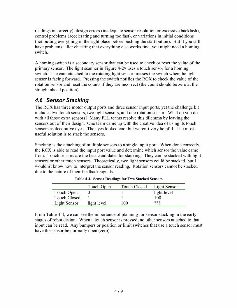
4-69
readings incorrectly), design errors (inadequate sensor resolution or excessive backlash),control problems (accelerating and turning too fast), or variations in initial conditions(not putting everything in the right place before pushing the start button). But if you stillhave problems, after checking that everything else works fine, you might need a homingswitch.
A homing switch is a secondary sensor that can be used to check or reset the value of theprimary sensor. The light scanner in Figure 4-29 uses a touch sensor for a homingswitch. The cam attached to the rotating light sensor presses the switch when the lightsensor is facing forward. Pressing the switch notifies the RCX to check the value of therotation sensor and reset the counts if they are incorrect (the count should be zero at thestraight ahead position).
4.6 Sensor StackingThe RCX has three motor output ports and three sensor input ports, yet the challenge kitincludes two touch sensors, two light sensors, and one rotation sensor. What do you dowith all those extra sensors? Many FLL teams resolve this dilemma by leaving thesensors out of their design. One team came up with the creative idea of using its touchsensors as decorative eyes. The eyes looked cool but werenít very helpful. The mostuseful solution is to stack the sensors.
Stacking is the attaching of multiple sensors to a single input port. When done correctly,the RCX is able to read the input port value and determine which sensor the value camefrom. Touch sensors are the best candidates for stacking. They can be stacked with lightsensors or other touch sensors. Theoretically, two light sensors could be stacked, but Iwouldnít know how to interpret the sensor reading. Rotation sensors cannot be stackeddue to the nature of their feedback signals.
Table 4-4. Sensor Readings for Two Stacked Sensors
Touch Open Touch Closed Light SensorTouch Open 0 1 light levelTouch Closed 1 1 100Light Sensor light level 100 ???
From Table 4-4, we can see the importance of planning for sensor stacking in the earlystages of robot design. When a touch sensor is pressed, no other sensors attached to thatinput can be read. Any bumpers or position or limit switches that use a touch sensor musthave the sensor be normally open (zero).

5-70
5 Robot DrivesA vast majority of robots, especially those used in industry, are of the stationary type.They may have hands to pick things up and arms to move things from here to there, butthey have no legs. Instead, they depend on other specialized machines to bring them thematerials they need for their work and cart off the fruits of their labor. The robotsdesigned for FLL are quite the opposite; they need to move. They have places to go andscientists to save, and all without any outside intervention or control. This kind of robotis commonly referred to as an Autonomous Robotic Vehicle or ARV, and it is among themost difficult kinds of robots to build and program.
The part of an ARV that is responsible for moving around is called the motion base ormotion platform. Early motion bases were exclusively wheeled platforms that only hadto move their robots around on a smooth laboratory floor. As robots moved out of thelab, automotive and tank type robots became increasingly popular. Nowadays, ARVísare zooming down the highway at 60mph, diving to the deepest depths of the ocean,walking down into the cauldrons of active volcanoes, flying surveillance over enemyarmies, and rolling over the surface of Mars.
The motion bases for FLL robots havenít been quite so exotic. Their operatingenvironment is closer to the smooth laboratory floor than the cauldron of an activevolcano. Wheeled platforms are the most common, but tracks are popular too. Somehave all-wheel-drive to help them climb inclines or traverse rugged terrain. A few teamshave tried automotive type platforms with steered front wheels, but most robots use somesort of differential steering arrangement where turning is performed by changing therelative speeds of the two drive motors.
Much of your robotís success will be determined on how well the strengths of its motionbase match the needs of your overall strategy. Whatís more important, speed oraccuracy? Is traveling in a perfectly straight line really required? Do your plans requirelots of turns and maneuvering in tight quarters? Is pulling capacity or load carryingcapacity important? What about obstacles, uneven terrain, surface variations? Manyquestions must be answered before building can begin.
5.1 Differential DriveDifferential drive motion platforms were very popular in early mobile robots. Twowheels mounted on a single axis are independently powered and controlled, providingboth drive and steering. Steering is performed by changing the relative velocities of thetwo drive wheels. Spinning the left wheel faster causes the robot to turn right. Spinningthe right wheel faster causes the robot to turn left. By spinning the wheels in oppositedirections, it is possible to turn in place, something that is impossible to do in anautomobile. Perhaps the most common example of a differential drive platform ineveryday life is the wheelchair.

5-71
Figure 5-1. A Differential Drive Robot
Differential drive robots are very popular in FLL. Iím sure this is in large part due totheir inclusion in the Constructopedia. However, they really are a good platform forrobot competitions. Differential drives are easy to design and build, making them a goodchoice for teams with young children. They are very agile and can be quite compact,allowing them to maneuver in tight spaces. Having two motors attached to the drivenwheels makes differential drive robots very powerful and capable of climbing inclinesthat would stop other robots.
5.1.1 CastersBecause it is hard to make a stable two wheeled vehicle, most differential drive robotshave one or more non-driven wheels to provide balance. Commonly called casters,idlers, or bogeys, the job of these wheels is to prevent the robot from tipping over whileat the same time having little or no impact on locomotion or steering. Unlike the drivenwheels that have only one axis of motion, these balance wheels must be able to turn inany direction. Upside-down ball rollers are perfectly suited for this task. Using skids canalso be a good solution if the floor is smooth and slippery.
Figure 5-2. Swivel Casters
But LEGO does not make ball bearings, and skids are not always appropriate. Therefore,FLL differential drive robots usually use a swivel caster. A swivel caster has one or morewheels which are attached to a pivoting horn. The horn is bent to offset the wheel axle

5-72
and pivot axle. This offset makes the caster wheel self aligning. When your robotchanges direction the caster automatically turns to the new heading.
Figure 5-3. Swivel Casters are Self Aligning
As a differential drive robot moves forward, the ground slides backwards beneath thecaster wheels. Friction between the wheel and ground generates a force pullingbackwards on the wheel. If the caster is pointed in the direction of travel, the drag forcejust causes the casterís wheel to turn. However, if the caster is not pointing in thedirection of travel, it generates an aligning torque which tends to pivot the caster. Theamount of aligning torque is proportional to the caster offset. Casters with a large offsetwill have higher aligning torques for a given steer angle. They are more stable andfollow better than casters with small offsets.
Figure 5-4. Casters Generate Steering Forces While Aligning
Increasing the offset will make a caster less twitchy, but it can also amplify caster steer,which is something that is not very desirable in robot applications. Caster steer issomething we are all familiar with from our experience with shopping carts. It is thetendency of the casters to steer the front end of the cart while they align themselves aftercompleting a turn. This is particularly noticeable if the cart is heavily loaded andstraightening after a sharp corner or reversing direction. While only mildly annoying in ashopping cart, it can be a real problem in a robot. Excessive caster steer makes yourrobot difficult to control and introduces errors in distance and steering measurements.
When the caster wheel is not aligned with the direction of travel it generates a sidewaysforce as it rolls, just as the front wheels of an automobile generate a sideways forceduring steering. If the friction between the wheel and the ground is too great to allow thecaster to skid, the force is exerted against the cart, causing the front end to movesideways. As the caster straightens out, the sideways motion becomes less and lessnoticeable.
TravelDirection
Caster Offset
Drag
Aligning Torque Steer
Angle
D O= Caster OffsetA = Steer AngleD = O x sin(A)F = Drag ForceT = Aligning Torque= F x D= F x O x sin(A)

5-73
Question: Drawing on your shopping cart experience, how can you
minimize the caster steer effect?
5.1.2 Wheel ConfigurationEarly differential drive robots often had a diamond shaped wheel configuration like thatshown in Figure 5-5. These robots used encoders (rotation sensors) on the two drivewheels to measure distance traveled and to control steering. Therefore, it was veryimportant that the drive wheels be in firm contact with the ground. By having castersboth fore and aft, it was possible to put the robotís center of gravity directly over thedrive wheels, which supported almost all of the robotís weight. This maximized thetraction of the drive wheels and minimized the forces generated by the casters aligning.
Figure 5-5. Diamond Shaped Wheel Layout
The diamond layout worked great in the lab, gliding along over the smooth flat floors, butit encountered some serious problems out in the real world. To achieve static stability(not fall over when standing still), a vehicle must have at least three wheels, not all on acommon axis, touching the ground. If the vehicle has more than three wheels there is noguarantee that all the wheels will be touching the ground at any given moment. Aproblem with the diamond wheel layout is that when one of the casters drives over abump it causes one of the drive wheels to lift up into the air. When this happens, therobot turns uncontrollably towards the raised wheel. By the time the caster gets over thebump, the robot is no longer certain of its heading and distance traveled.
A three wheeled triangle configuration fixes this problem, but it loses some of theadvantages of the diamond layout. With only three wheels, you are guaranteed to haveall three wheels in contact with the ground. Unfortunately, using three wheels also meansthat the center of gravity cannot be centered over the drive wheel axis, and some of therobotís weight will be supported by the caster. To compensate, robot designers positionthe CG as close to the drive wheel axis and as far away from the caster as possible.Moving the caster farther away from the drive wheels also helps.
CG
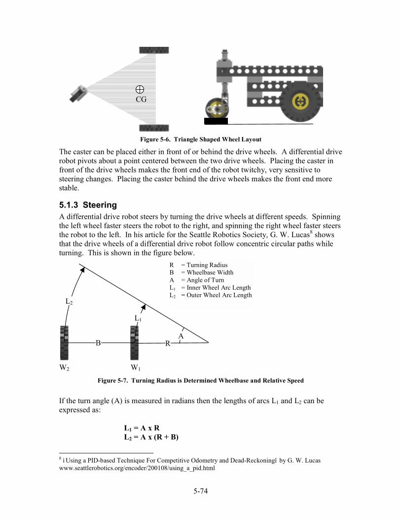
5-74
Figure 5-6. Triangle Shaped Wheel Layout
The caster can be placed either in front of or behind the drive wheels. A differential driverobot pivots about a point centered between the two drive wheels. Placing the caster infront of the drive wheels makes the front end of the robot twitchy, very sensitive tosteering changes. Placing the caster behind the drive wheels makes the front end morestable.
5.1.3 SteeringA differential drive robot steers by turning the drive wheels at different speeds. Spinningthe left wheel faster steers the robot to the right, and spinning the right wheel faster steersthe robot to the left. In his article for the Seattle Robotics Society, G. W. Lucas8 showsthat the drive wheels of a differential drive robot follow concentric circular paths whileturning. This is shown in the figure below.
Figure 5-7. Turning Radius is Determined Wheelbase and Relative Speed
If the turn angle (A) is measured in radians then the lengths of arcs L1 and L2 can beexpressed as:
L1 = A x RL2 = A x (R + B)
8 ì Using a PID-based Technique For Competitive Odometry and Dead-Reckoningî by G. W. Lucaswww.seattlerobotics.org/encoder/200108/using_a_pid.html
CG
B R
L1
L2
A
R = Turning RadiusB = Wheelbase WidthA = Angle of TurnL1 = Inner Wheel Arc LengthL2 = Outer Wheel Arc Length
W1W2
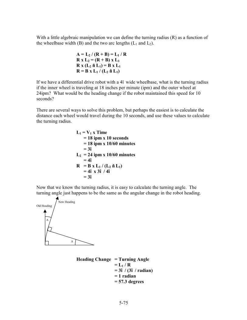
5-75
With a little algebraic manipulation we can define the turning radius (R) as a function ofthe wheelbase width (B) and the two arc lengths (L1 and L2).
A = L2 / (R + B) = L1 / RR x L2 = (R + B) x L1R x (L2 ñ L1) = B x L1R = B x L1 / (L2 ñ L1)
If we have a differential drive robot with a 4î wide wheelbase, what is the turning radiusif the inner wheel is traveling at 18 inches per minute (ipm) and the outer wheel at24ipm? What would be the heading change if the robot maintained this speed for 10seconds?
There are several ways to solve this problem, but perhaps the easiest is to calculate thedistance each wheel would travel during the 10 seconds, and use these values to calculatethe turning radius.
L1 = V1 x Time= 18 ipm x 10 seconds= 18 ipm x 10/60 minutes= 3î
L2 = 24 ipm x 10/60 minutes= 4î
R = B x L1 / (L2 ñ L1)= 4î x 3î / 4î= 3î
Now that we know the turning radius, it is easy to calculate the turning angle. Theturning angle just happens to be the same as the angular change in the robot heading.
Heading Change = Turning Angle= L1 / R= 3î / (3î / radian)= 1 radian= 57.3 degrees
Old Heading
New Heading
A
A
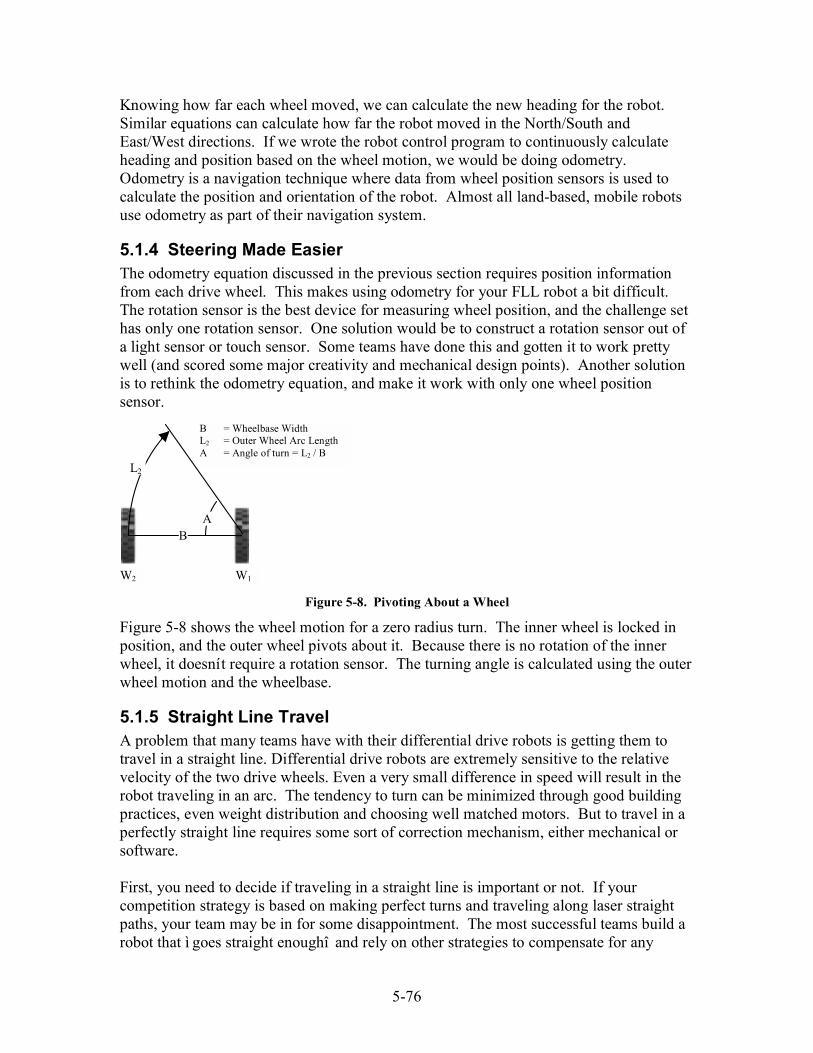
5-76
Knowing how far each wheel moved, we can calculate the new heading for the robot.Similar equations can calculate how far the robot moved in the North/South andEast/West directions. If we wrote the robot control program to continuously calculateheading and position based on the wheel motion, we would be doing odometry.Odometry is a navigation technique where data from wheel position sensors is used tocalculate the position and orientation of the robot. Almost all land-based, mobile robotsuse odometry as part of their navigation system.
5.1.4 Steering Made EasierThe odometry equation discussed in the previous section requires position informationfrom each drive wheel. This makes using odometry for your FLL robot a bit difficult.The rotation sensor is the best device for measuring wheel position, and the challenge sethas only one rotation sensor. One solution would be to construct a rotation sensor out ofa light sensor or touch sensor. Some teams have done this and gotten it to work prettywell (and scored some major creativity and mechanical design points). Another solutionis to rethink the odometry equation, and make it work with only one wheel positionsensor.
Figure 5-8. Pivoting About a Wheel
Figure 5-8 shows the wheel motion for a zero radius turn. The inner wheel is locked inposition, and the outer wheel pivots about it. Because there is no rotation of the innerwheel, it doesnít require a rotation sensor. The turning angle is calculated using the outerwheel motion and the wheelbase.
5.1.5 Straight Line TravelA problem that many teams have with their differential drive robots is getting them totravel in a straight line. Differential drive robots are extremely sensitive to the relativevelocity of the two drive wheels. Even a very small difference in speed will result in therobot traveling in an arc. The tendency to turn can be minimized through good buildingpractices, even weight distribution and choosing well matched motors. But to travel in aperfectly straight line requires some sort of correction mechanism, either mechanical orsoftware.
First, you need to decide if traveling in a straight line is important or not. If yourcompetition strategy is based on making perfect turns and traveling along laser straightpaths, your team may be in for some disappointment. The most successful teams build arobot that ì goes straight enoughî and rely on other strategies to compensate for any
B
L2
A
B = Wheelbase WidthL2 = Outer Wheel Arc LengthA = Angle of turn = L2 / B
W1W2
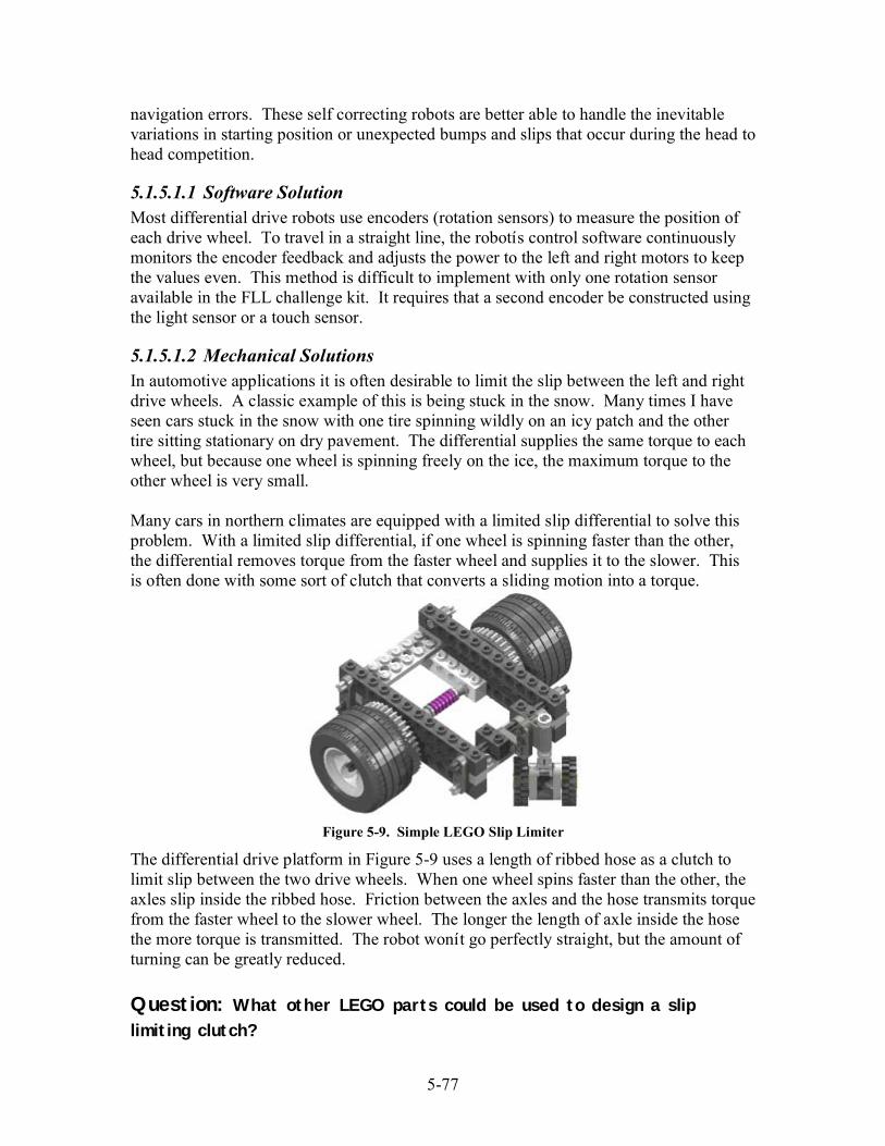
5-77
navigation errors. These self correcting robots are better able to handle the inevitablevariations in starting position or unexpected bumps and slips that occur during the head tohead competition.
5.1.5.1.1 Software SolutionMost differential drive robots use encoders (rotation sensors) to measure the position ofeach drive wheel. To travel in a straight line, the robotís control software continuouslymonitors the encoder feedback and adjusts the power to the left and right motors to keepthe values even. This method is difficult to implement with only one rotation sensoravailable in the FLL challenge kit. It requires that a second encoder be constructed usingthe light sensor or a touch sensor.
5.1.5.1.2 Mechanical SolutionsIn automotive applications it is often desirable to limit the slip between the left and rightdrive wheels. A classic example of this is being stuck in the snow. Many times I haveseen cars stuck in the snow with one tire spinning wildly on an icy patch and the othertire sitting stationary on dry pavement. The differential supplies the same torque to eachwheel, but because one wheel is spinning freely on the ice, the maximum torque to theother wheel is very small.
Many cars in northern climates are equipped with a limited slip differential to solve thisproblem. With a limited slip differential, if one wheel is spinning faster than the other,the differential removes torque from the faster wheel and supplies it to the slower. Thisis often done with some sort of clutch that converts a sliding motion into a torque.
Figure 5-9. Simple LEGO Slip Limiter
The differential drive platform in Figure 5-9 uses a length of ribbed hose as a clutch tolimit slip between the two drive wheels. When one wheel spins faster than the other, theaxles slip inside the ribbed hose. Friction between the axles and the hose transmits torquefrom the faster wheel to the slower wheel. The longer the length of axle inside the hosethe more torque is transmitted. The robot wonít go perfectly straight, but the amount ofturning can be greatly reduced.
Question: What other LEGO parts could be used to design a slip
limiting clutch?

5-78
Sometimes a limited slip differential isnít enough. To eliminate slip between the left andright drive wheels, some off road vehicles are equipped with a locking differential. Alocking differential has a switch that allows it to work like a normal differential, or forcesit to behave like a solid axle.
Figure 5-10. A Locking Differential
Way back in the Gears chapter, we talked about how a differential can be used tomeasure the speed difference between two tires by reversing the rotation of one of theinput shafts. This forms the basis for a LEGO locking differential. Preventing thedifferential in Figure 5-10 from rotating makes the drive train behave as though the leftand right wheels were attached to a single axle. Unlocking the differential allows thewheels to spin independently.
Question: Some vehicles have a button or lever in the passenger
compartment for locking and unlocking the differential. Can you think of
a scheme where the RCX could lock and unlock our LEGO implementation?
5.1.6 Differential SkidDifferential skid, sometimes referred to as skid-steer, is a variation of the differentialdrive. Itís normally used with tracked vehicles (like tanks), but sometimes with 4 or 6wheel platforms (like the Bobcat skid loader or Gator ATV) as well. Casters are not usedin a differential skid drive; all the wheels are driven. Wheels on the left side are drivenby one motor, wheels on the right by another.
Skid steer configurations rely on track or wheel slippage for steering. As a consequence,the wheel position information cannot be used for reliable odometry. For this reason,skid steering is usually reserved for tele-operated (remote controlled) roboticapplications. Non-driven measurement wheels can be added to obtain odometryinformation for autonomous operation.

5-79
Figure 5-11. A Pair of Differential Skid Robots
Many differential skid robots have competed in Minnesota FLL competitions over thepast few years, and several have done quite well. The successful teams developedstrategies that maximized their robotsí strengths and minimized their robotsí weaknesses.Skid steer robots are good climbers and can handle rougher terrain than most other robotdesigns. They are as maneuverable as a differential drive robot, but less prone tounwanted differential steer. And poor odometry data isnít a problem if your robot usesline following or some other landmark-based strategy for navigation.
5.2 Steering driveA steering drive is the familiar configuration used in automobiles. In a steering drive,one motor is used for locomotion and a second motor for steering. Decoupling steeringfrom forward motion makes a steering drive easier to control than a differential drivewhere the velocity of each drive wheel must always be carefully measured andcontrolled. Front wheeled steering provides accurate odometry while supporting thetraction and ground clearance needs of all-terrain operation. This makes it a popularchoice for outdoor autonomous vehicles.
In general, a steering drive robot is more difficult to build than a differential drive robot.It needs a differential to transfer the power of the drive motor to the wheels. Extragearing is usually required to amplify the torque output of the single drive motor. Thesteering mechanism can also be difficult to design using the parts available in the RIS kit.Luckily, there are many Technic steering drive examples on the web. A quick search onLUGNET revealed over 100 different steering drive vehicles.
Figure 5-12 shows two different steering drive robots. The robot on the left uses crowngears and spur gears to pivot the front axles. The robot on the right has rack and pinionsteering just like most cars on the road today. The robot on the right uses a special gearrack that is available in many Technic vehicle sets, but a similar mechanism could bebuilt using the gear racks supplied in the RIS kit.

5-80
Figure 5-12. Two steered wheel robots
5.2.1 TurningA steering drive robot has a non-zero turning radius. This means that unlike a differentialdrive robot, a steering drive robot must translate (move forward, backwards, and/orsideways) while turning. Such systems are said to be non-holonomic. In a non-holonomic robot, one or more of the degrees-of-freedom (heading, position) cannot becontrolled independently. This makes path planning more difficult because each headingchange will have an accompanying position change. Non-holonomic vehicles can beparticularly difficult to navigate in tight spaces. Remember the last time you parallelparked?
Figure 5-13. Path Planning is Harder for Non-Holonomic Robots
The only odometry information I could find on the web was for steering platforms withAckerman correction. Used in almost every vehicle you see on the road, Ackermansteering correction is a modified steering geometry that minimizes wheel skid whenturning. During steering, the four wheels of a steering drive travel along four concentricarcs. As seen in Figure 5-14, the front wheels of a vehicle with Ackerman correction areoriented such that the extended axis of the wheels passes through the center of these arcs.This requires the inner wheel to turn at a sharper angle than the outer wheel.
Differential Drive Steering Drive

5-81
Figure 5-14. Ackerman Steering Minimizes Geometry Induced Wheel Skid
Without Ackerman correction, the front wheels both turn the same amount when steering.This results in them trying to travel along arcs with different centers. As the vehicleturns, one or both of the front wheels are forced to skid sideways, generating large forceson the steering components and producing excessive wear on the tires. More importantfor robotics applications, is the fact that you canít calculate solutions for the odometryequations because the turning center cannot be absolutely determined.
Itís possible but difficult to build a LEGO steering drive with Ackerman correction. Ifound some web pages with calculators for designing the components and geometry and afew books devoted to the subject. Unfortunately, the solutions require using specificallysized components that often donít map well to my available LEGO pieces.
A simpler solution is to use only one steered wheel. Three wheeled steering drives aremost common in specialized niche markets like golf or meter reader carts. Their maindisadvantage, a tendency to tip over when turning at high speed, is not a big problem inthese applications. However, a three wheeled platformís simpler construction andodometry makes it a good choice for a LEGO robot.
Figure 5-15. Turning Radius is Determined by Wheel Base and Steering Angle
With Ackerman Correction Without Ackerman Correction
Turning Center Turning Center?
R
A
L
A
A = Steer AngleL = Wheelbase LengthR = Turning Radius= L / sin(A)

5-82
As shown in Figure 5-15, the turning radius of a steering drive is determined by thelength of the wheelbase and the steer angle of the front wheel(s). This is why long truckshave a large turning radius and small sports cars a tight turning radius.
Letís say we have a steering drive robot with a 6î long wheelbase and a maximum steerangle of 30 degrees. What is the minimum turning radius for the front wheel, and howfar would the front wheel travel while completing a 45 degree turn?
Turning Radius = L / sin(A)= 6î / sin(30 degrees )= 12î
Travel Distance = Radius x Angle (in radians)= 12î x 45 degrees x (Pi radians / 180 degrees)= 12î x Pi / 4= 9.42î
5.2.2 Tricycle DriveA tricycle drive is a steered drive platform with a single driven front wheel and twopassive rear wheels (or vice versa). Though it may look very similar to a three wheeledsteering drive platform, a tricycle drive has some unique characteristics that make itpreferable for most robotic applications. The most important of these is its ability to turnin place.
Figure 5-16. Tricycle Drive (Left) and Steering Drive (Right) Robots Look Similar
As discussed in the previous section, the minimum turning radius for a steering drive isdetermined by the maximum steer angle and the length of the wheelbase, R = L / sin(A).If the maximum steer angle was 90 degrees, then the turning radius would be equal to thewheelbase length. The robot could pivot about a point midway between the two rearwheels.
Unfortunately, a steering drive will not turn if the steer angle is 90 degrees. If the vehiclemoves at all, the front wheel(s) skid sideways instead of rolling. This is because the drive
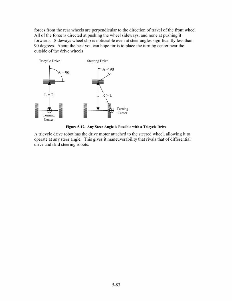
5-83
forces from the rear wheels are perpendicular to the direction of travel of the front wheel.All of the force is directed at pushing the wheel sideways, and none at pushing itforwards. Sideways wheel slip is noticeable even at steer angles significantly less than90 degrees. About the best you can hope for is to place the turning center near theoutside of the drive wheels
Figure 5-17. Any Steer Angle is Possible with a Tricycle Drive
A tricycle drive robot has the drive motor attached to the steered wheel, allowing it tooperate at any steer angle. This gives it maneuverability that rivals that of differentialdrive and skid steering robots.
L = R
A = 90
TurningCenter
L
A < 90
TurningCenter
R > L
Tricycle Drive Steering Drive