building maintenance unit - fba gomyl building maintenance unit – bmu ... systematically over a...
TRANSCRIPT
Building Maintenance Unit 10/Jan/2017 1
Building Maintenance Unit
fba-gomyl.com
Building Maintenance Unit 10/Jan/2017 2
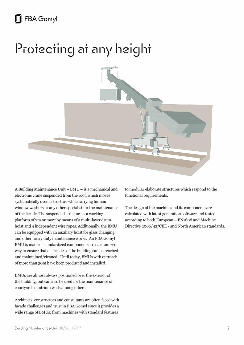
A Building Maintenance Unit – BMU – is a mechanical and electronic crane suspended from the roof, which moves systematically over a structure while carrying human window washers or any other specialist for the maintenance of the facade. The suspended structure is a working platform of 2m or more by means of a multi-layer drum hoist and 4 independent wire ropes. Additionally, the BMU can be equipped with an auxiliary hoist for glass changing and other heavy duty maintenance works. An FBA Gomyl BMU is made of standardized components in a customized way to ensure that all facades of the building can be reached and maintained/cleaned. Until today, BMUs with outreach of more than 30m have been produced and installed.
BMUs are almost always positioned over the exterior of the building, but can also be used for the maintenance of courtyards or atrium walls among others.
Architects, constructors and consultants are often faced with facade challenges and trust in FBA Gomyl since it provides a wide range of BMUs; from machines with standard features
to modular elaborate structures which respond to the functional requirements.
The design of the machine and its components are calculated with latest generation software and tested according to both European – EN1808 and Machine Directive 2006/42/CEE - and North American standards.
Protecting at any height

Building Maintenance Unit 10/Jan/2017 3
A Building Maintenance Unit – BMU – is a mechanical andelectronic crane suspended from the roof, which movessystematically over a structure while carrying humanwindow washers or any other specialist for the maintenanceof the facade. The suspended structure is a workingplatform of 2m or more by means of a multi-layer drumhoist and 4 independent wire ropes. Additionally, the BMUcan be equipped with an auxiliary hoist for glass changingand other heavy duty maintenance works. An FBA GomylBMU is made of standardized components in a customizedway to ensure that all facades of the building can be reachedand maintained/cleaned.
BMUs are almost always positioned over the exterior ofthe building, but can also be used for the maintenance ofcourtyards or atrium walls among others.
The design of the machine and its components arecalculated with latest generation software and testedaccording to both European – EN1808 and MachineDirective 2006/42/CEE - and North American standards.
The BMU 1 model is the lightest solution for buildings where the cradle needs to be positioned not parallel to the railtrack, where the mast and a single jib can rotate allowing multiple working positions. 1. Base Frame
The base frame has four wheelsets suitable for the track existing in site. The two front wheel assemblies are centrically fitted under the frame.
Both front wheels are connected to an electric geared motor drive. The two rear wheel assembly arms are swiveling type for negotiating bends. They are provided with vertical allowances for compensating levels of track. Limit switches at the arm pivot ensure speed difference between front and rear wheels while negotiating bends.
FBA 1: Best system to cover the whole perimeter of a building
BMU FBA 1 installed in Spain. The rails are fixed to an upper structure behind a 3m high parapet. The machine has a jib luffing, in order to pass the cradle over the parapet.

Building Maintenance Unit 10/Jan/2017 4
2. Crane house with jib
The cranehouse that houses the hoist unit and main slew drive system is mounted to the baseframe by means of a slewing ring with electrical drive to allow the crew to slew the cradle from its non-working position on the roof to the working position in front of the facade. The crane house designed to rigidly support the jib with luffing mechanism and the hoist unit.
3. Jib
The jib is fitted to the cranehouse frame in a fixed or a hinge joint with suitable bearing arrangement. A luffing device, consisting of an electric motor with screw spindle and traveling nut, can be installed to allow a luffing movement of the jib to adjust the distance between cradle and facade and pass the cradle trough high parapets.
Easily operated. A Rope Access Technician Certification is not required.
4. Hoist unit
The hoist unit consists of a brake motor of irreversible type with a second centrifugal brake, a gear box and a cable drum divided into 4-sections. The drum has helical groves to allow the rope to wind efficiently. At the end of each layer, the direction of motion changes to fill the following layer. Both ends of the drum are supported, namely one end in a Internal slew ring bearing support and the other end in an overspeed device with bearing and expansion joint. The suspension ropes have core conductors of suitable capacity to control all the functions of the power unit from cradle control panel through a slip ring mechanism mounted to the drive of the hoist unit.
5. Cradle
The super structure of the cradle is built of Aluminum alloy 6060 T6. The super structure has aluminum cladding all around. The cradle is provided with protective rubber
cushions to prevent damage to the building. A trip bar under the cradle stops the descent of the platform when an obstruction is encountered. A control panel inside the cradle with dead-man type push buttons control system allow controlling of the motions of the roof trolley. The cradle is suspended by four suspension ropes, namely two hoisting ropes and two safety ropes through wedge sockets, over load device and rope equalizing mechanism. The special shape of the cradle will allow access to required portions of the facade.
6. Scope of Supply
Following a scope of supply of a typical FBA 1 B.M.U. However, each machine is customized according to the building, project and client’s requirements, so it may vary.
FBA 1 with jib luffing, in order to pass the cradle over the high parapet. Installed in Doha, Qatar.

Building Maintenance Unit 10/Jan/2017 5
6.1. Cradle (Four rope suspension system in aluminium).• Two fixing points for safety belts• Two light coloured protecting profiles • One anti slip flooring • One soft foam distance roller
6.2. Roofcar (welded).• One jib with/without luffing device• Two horizontal bearings• One winch housing with inspection door• One multi layer drum winch with rope• Lay down device• One primary brake• One secondary brake• One bevel wheel geared brake motor with manual brake
release and emergency decent• One spring loaded cable wheeler - Fixed or
motorised spreader bar• One slewing ring between winch housing and
under carriage for 350 degree turning• One four point traversing unit with two electrical
geared brake motors and two self adjusting rear wheels• One control panel with PLC control and self Diagnostic
system. Machine status on display
6.3. Control elements. • One control box in cradle• One anti collision bar
FBA 1 B.M.U. installed in Spain. The machine design is optimized making it lightweight and inconspicuous in the building roof, in a custom color as per client’s requirements.
• One control box at roof car• Four rope lay down detectors• Four slack rope detectors• One limit switch spring loaded cable wheeler• One limit switch secondary brake• Two limit switches final position luffing device• Two limit switches slewing roof car• Two limit switches traversing gear• One limit switch max. working position of cradle• One overload device cradle
7. Technical Data
Following the Technical Data of a typical FBA 1 B.M.U. However, each machine is customized according to the building, project and client’s requirements, so it may vary.
7.1. General.Designed, engineered, manufactured and tested according to EN 1808.• Safe Working Load: 200-350 kg• Hoisiting height: 0-300 m• Wheel gauge: 600-3000 mm• Wheel base: 600-3000 mm• Outreach max.: 20 m
7.2. Cradle.• Length: 2000-9000 mm• Width: 600 mm• Height: 1000/1200 mm
7.3. Ropes.• Nominal diameter: 8 mm• Number of ropes: 4• Construction: 114 wires - seale similar DIN 3058• Calculated breaking load: 44,40 kN• Min. breaking load: 38,20 kN• Calculated weight: 0,234 kg/m• Copper conductor: 0,96 mm2
• Safety factor min: 14• Tensile grade of wire: 1770 N/mm2
Building Maintenance Unit 10/Jan/2017 6
7.4. Material selection / corrosion protection.• Roofcar: RSt 37 - 2 hot dip galvanized• Undercarriage: RSt 37 - 2 hot dip galvanized• Jib: RSt 37 - 2 hot dip galvanized• Cradle: Aluminum• Exterior bolts and nuts: Austennitic stainless steel• High tensile bolts: HT - material, hot dip galvanized• Paint: 2 x 40 µm. Color code according to customer’s
specification
7.5. Electrical equipment.• Voltage: 380 Volt (others on request)• Frequency: 50 Hz (others on request)• Power supply: 3 Phase + PE + N• Hoisting drive: Bevel wheel geared brake motor with
manual brake release and emergency decent 1 x 2,2 KW• Actuator slew ring: Bevel wheel geared brake motor
with manual brake release 1 x 0,55 KW• Actuator traversing: Geared motor 2 x 0,25KW
7.6. Power supply roofcar.• Power supply: Spring loaded cable drum 5 x 2,5 mm2
• Length: 25 m• Max. distance: 2 x 20 m
7.6. Control panel.• Protection: IP 55• Wattage: 3,5 KW• Supply rating: 20 Ampere
7.8. Controls.• Roofcar: Single maneuver selector with display. Start
up push button and emergency stop push button• Cradle: Single maneuver selector with display. Start up
push button and emergency stop push button• Signal transmission: Copper conductors in wire rope• Control voltage: 24V
8. Accesories / Optional Extras
The machine can be equipped with additional accesories as per project requirements:- 30 l Watertank in cradle - Material hoist 350 kg (others on request)- Soft starting motors- Facade Restraints (buildings in Excess of 40 m)
Some projects may require specific accesories which can be added as per client’s requirements.
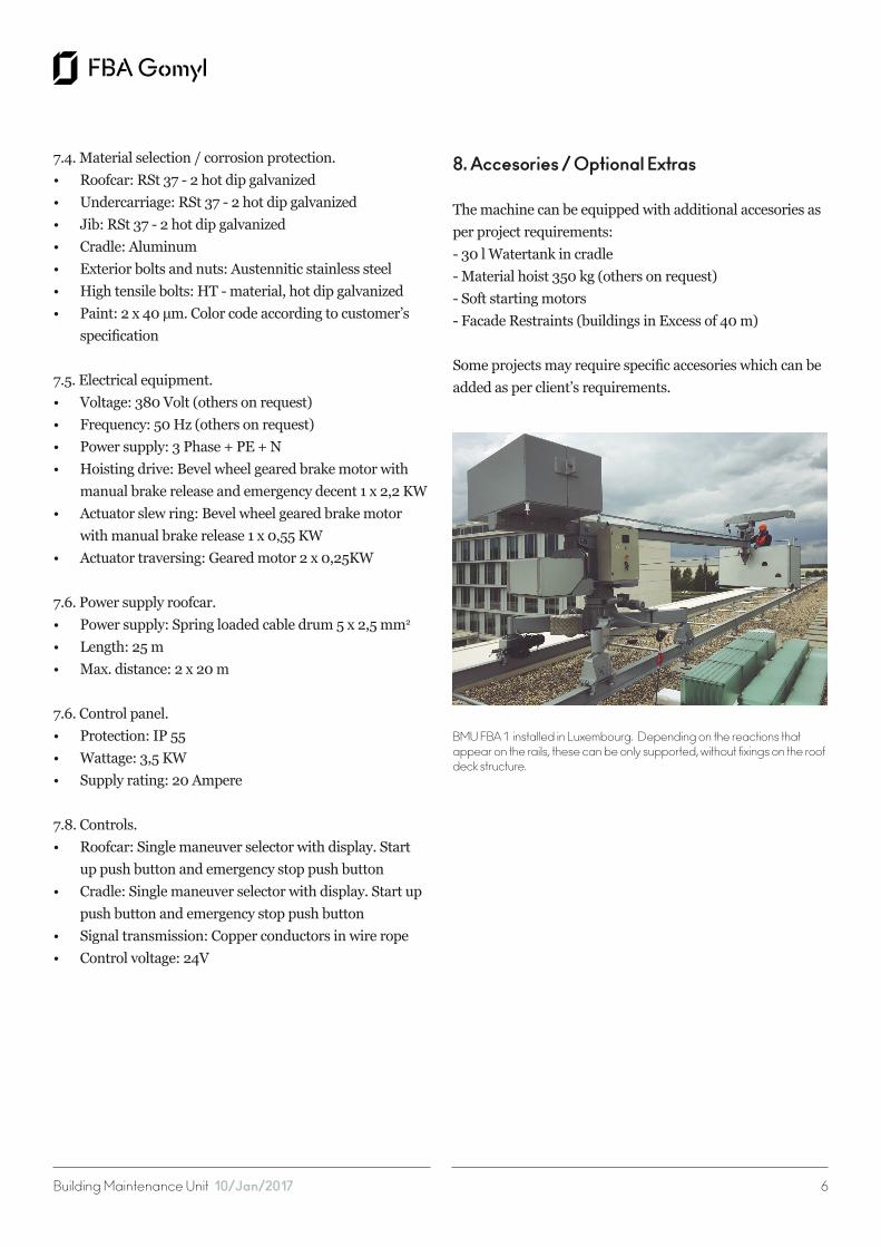
BMU FBA 1 installed in Luxembourg. Depending on the reactions that appear on the rails, these can be only supported, without fixings on the roof deck structure.

Building Maintenance Unit 10/Jan/2017 7
A Building Maintenance Unit – BMU – is a mechanical andelectronic crane suspended from the roof, which movessystematically over a structure while carrying humanwindow washers or any other specialist for the maintenanceof the facade. The suspended structure is a workingplatform of 2m or more by means of a multi-layer drumhoist and 4 independent wire ropes. Additionally, the BMUcan be equipped with an auxiliary hoist for glass changingand other heavy duty maintenance works. An FBA GomylBMU is made of standardized components in a customizedway to ensure that all facades of the building can be reachedand maintained/cleaned.
BMUs are almost always positioned over the exterior ofthe building, but can also be used for the maintenance ofcourtyards or atrium walls among others.
The design of the machine and its components arecalculated with latest generation software and testedaccording to both European – EN1808 and MachineDirective 2006/42/CEE - and North American standards.
The BMU 2 model is the lightest solution and the most standarized machine for small buildings. The two jibs allow, with only one rotatory axis, working positions with different reaches and a parking position for the cradle.
1. Base Frame
The base frame has four wheelsets suitable for the track existing in site. The two front wheel assemblies are centrically fitted under the frame. Both front wheels are connected to an electric geared motor drive. The two rear wheel assembly arms are swiveling type for negotiating bends.
They are provided with vertical allowances for compensating levels of track. Limit switches at the arm
pivot ensure speed difference between front and rear wheels while negotiating bends.
2. Crane house with jibs
The cranehouse that houses the hoist unit and main slew drive system is mounted to the baseframe by means of a slewing ring with electrical drive to allow the crew to slew the cradle from its non-working position on the roof to the working position in front of the facade. The crane house designed to rigidly support the jibs with luffing mechanism and the hoist unit.
FBA 2: The lightest BMU solution
BMU FBA Type 2: the standard lightest machine.

Building Maintenance Unit 10/Jan/2017 8
3. Jibs
The jibs are fitted to the cranehouse frame in a hinge joint with suitable bearing arrangement. A luffing device, consisting of an electric motor with screw spindle and traveling nut, allow a luffing movement of the jib to adjust the distance between cradle and facade.
4. Hoist unit
The hoist unit consists of a brake motor of irreversible type with a second centrifugal brake, a gear box and a cable drum divided into 4-sections. The drum has helical groves to allow the rope to wind efficiently. At the end of each layer, the direction of motion changes to fill the following layer. Both ends of the drum are supported, namely one end in a Internal slew ring bearing support and the other end in an overspeed device with bearing and expansion joint. The suspension ropes have core conductors of suitable capacity to control all the functions of the power unit from cradle control panel through a slip ring mechanism mounted to the drive of the hoist unit.
Modular system, which allows augmentation or exclusion of elements.
5. Cradle
The super structure of the cradle is built of Aluminum alloy 6060 T6. The super structure has aluminum cladding all around. The cradle is provided with protective rubber cushions to prevent damage to the building. A trip bar under the cradle stops the descent of the platform when an obstruction is encountered. A control panel inside the cradle with dead-man type push buttons control system allow controlling of the motions of the roof trolley. The cradle is suspended by four suspension ropes, namely two hoisting ropes and two safety ropes through wedge sockets, over load device and rope equalizing mechanism.
The special shape of the cradle will allow access to required portions of the facade.
6. Scope of Supply
Following a scope of supply of a typical FBA 2 B.M.U. However, each machine is customized according to the building, project and client’s requirements, so it may vary.
6.1. Cradle (Four rope suspension system in aluminium).• Two fixing points for safety belts• Two light coloured protecting profiles • One anti slip flooring • One soft foam distance roller
FBA 2 in parking position, just after its installation.
Building Maintenance Unit 10/Jan/2017 9
6.2. Roofcar (welded).• Two jibs with one luffing device• Two horizontal bearings• One winch housing with inspection door• One multi layer drum winch with rope• Lay down device• One primary brake• One secondary brake• One bevel wheel geared brake motor with manual
6.3. Control elements. • One control box in cradle• One anti collision bar• One control box at roof car• Four rope lay down detectors• Four slack rope detectors• One limit switch spring loaded cable wheeler• One limit switch secondary brake• Two limit switches final position luffing device• Two limit switches slewing roof car• Two limit switches traversing gear• One limit switch max. working position of cradle• One overload device cradle
7. Technical Data
Following the Technical Data of a typical FBA 2 B.M.U. However, each machine is customized according to the building, project and client’s requirements, so it may vary.
7.1. General.Designed, engineered, manufactured and tested according to EN 1808.• Safe Working Load: 200-350 kg• Hoisiting height: 0-300 m• Wheel gauge: 600-3000 mm• Wheel base: 600-3000 mm• Outreach max.: 8000 mm
7.2. Cradle.• Length: 2000-9000 mm• Width: 600 mm• Height: 1000/1200 mm
7.3. Ropes.• Nominal diameter: 8 mm• Number of ropes: 4• Construction: 114 wires - seale similar DIN 3058• Calculated breaking load: 44,40 kN• Min. breaking load: 38,20 kN• Calculated weight: 0,234 kg/m• Copper conductor: 0,96 mm2
• Safety factor min: 14• Tensile grade of wire: 1770 N/mm2
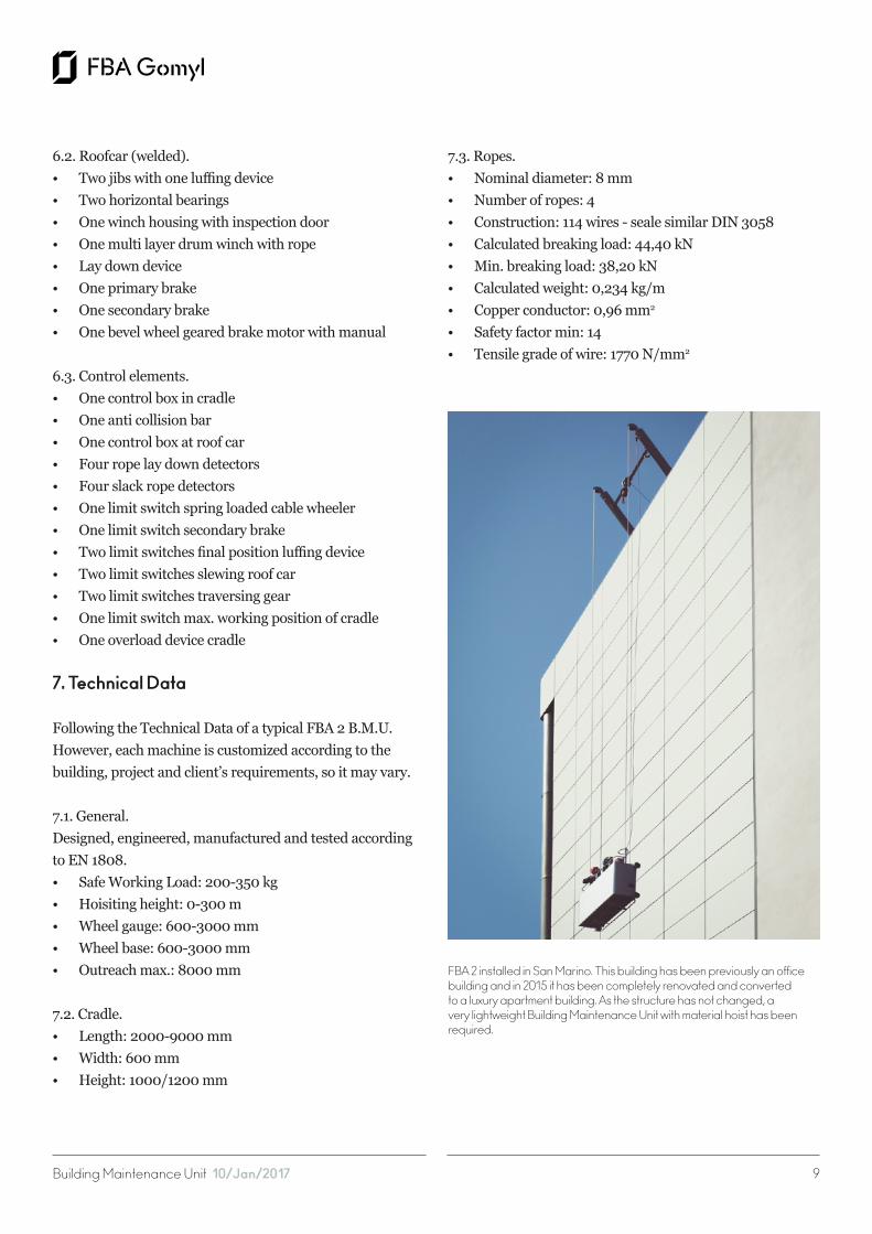
FBA 2 installed in San Marino. This building has been previously an office building and in 2015 it has been completely renovated and converted to a luxury apartment building. As the structure has not changed, a very lightweight Building Maintenance Unit with material hoist has been required.
Building Maintenance Unit 10/Jan/2017 10
7.4. Material selection / corrosion protection.• Roofcar: RSt 37 - 2 hot dip galvanized• Undercarriage: RSt 37 - 2 hot dip galvanized• Jib: RSt 37 - 2 hot dip galvanized• Cradle: Aluminum• Exterior bolts and nuts: Austennitic stainless steel• High tensile bolts: HT - material, hot dip galvanized• Paint: 2 x 40 µm. Color code according to customer’s
specification
7.5. Electrical equipment.• Voltage: 380 Volt (others on request)• Frequency: 50 Hz (others on request)• Power supply: 3 Phase + PE + N• Hoisting drive: Bevel wheel geared brake motor with
manual brake release and emergency decent 1 x 2,2 KW• Actuator slew ring: Bevel wheel geared brake motor
with manual brake release 1 x 0,55 KW• Actuator traversing: Geared motor 2 x 0,25KW• Actuator luffing device: Hydraulicpump 0,55 KW
7.6. Power supply roofcar.• Power supply: Spring loaded cable drum 5 x 2,5 mm2
• Length: 25 m• Max. distance: 2 x 20 m
7.7. Control panel.• Protection: IP 55• Wattage: 3,5 KW• Supply rating: 20 Ampere
7.8. Controls.• Roofcar: Single maneuver selector with display. Start
up push button and emergency stop push button• Cradle: Single maneuver selector with display. Start up
push button and emergency stop push button• Signal transmission: Copper conductors in wire rope• Control voltage: 42V
8. Accesories / Optional Extras
The machine can be equipped with additional accesories as per project requirements:• 30 l Watertank in cradle • Material hoist 350 kg (others on request)• Soft starting motors• Facade Restraints (buildings in Excess of 40 m)
Some projects may require specific accesories which can be added as per client’s requirements.
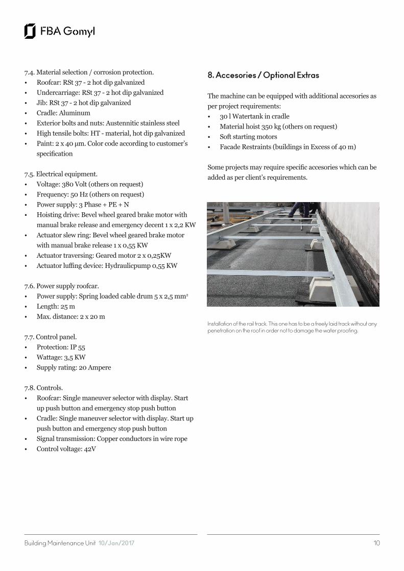
Installation of the rail track. This one has to be a freely laid track without any penetration on the roof in order not to damage the water proofing.

Building Maintenance Unit 10/Jan/2017 11
A Building Maintenance Unit – BMU – is a mechanical andelectronic crane suspended from the roof, which movessystematically over a structure while carrying humanwindow washers or any other specialist for the maintenanceof the facade. The suspended structure is a workingplatform of 2m or more by means of a multi-layer drumhoist and 4 independent wire ropes. Additionally, the BMUcan be equipped with an auxiliary hoist for glass changingand other heavy duty maintenance works. An FBA GomylBMU is made of standardized components in a customizedway to ensure that all facades of the building can be reachedand maintained/cleaned.
BMUs are almost always positioned over the exterior ofthe building, but can also be used for the maintenance ofcourtyards or atrium walls among others.
The design of the machine and its components arecalculated with latest generation software and testedaccording to both European – EN1808 and MachineDirective 2006/42/CEE - and North American standards.
The BMU S model is the solution for buildings with high heights, complex geometries, long reaches and special requirements. The customized jib and mast allow reaching working positions in the facade which would not be possible with standard machines.
FBA S: The maintenance solution for great heights buildings

Building Maintenance Unit 10/Jan/2017 12
1. Base Frame
The base frame has four wheelsets suitable for the track existing in site. The two front wheel assemblies are centrically fitted under the frame. Both front wheels are connected to an electric geared motor drive. The two rear wheel assembly arms are swiveling type for negotiating bends. They are provided with vertical allowances for compensating levels of track. Limit switches at the arm pivot ensure speed difference between front and rear wheels while negotiating bends.
2. Crane house with jibs
The cranehouse that houses the hoist unit and main slew drive system is mounted to the baseframe by means of a slewing ring with electrical drive to allow the crew to slew the cradle from its non-working position on the roof to the working position in front of the facade. The crane house designed to rigidly support the jib with luffing mechanism if needed and the hoist unit.
Tailored design to all complex facade geometries.
3. Jib
The jib is fitted to the cranehouse frame in a fixed or a hinge joint with suitable bearing arrangement. A luffing device, consisting of an electric motor with screw spindle and traveling nut, can be installed to allow a luffing movement of the jib to adjust the distance between cradle and facade and pass the cradle trough high parapets.
4. Hoist unit
The hoist unit consists of a brake motor of irreversible type with a second centrifugal brake, a gear box and a cable drum divided into 4-sections. The drum has helical groves to allow the rope to wind efficiently. At the end of each layer, the direction of motion changes to fill the following layer. Both ends of the drum are supported, namely one end in a Internal slew ring bearing support and the other end in an overspeed device with bearing and expansion joint. The
suspension ropes have core conductors of suitable capacity to control all the functions of the power unit from cradle control panel through a slip ring mechanism mounted to the drive of the hoist unit.
5. Cradle
The super structure of the cradle is built of Aluminum alloy 6060 T6. The super structure has aluminum cladding all around. The cradle is provided with protective rubber cushions to prevent damage to the building. A trip bar under the cradle stops the descent of the platform when an obstruction is encountered. A control panel inside the cradle with dead-man type push buttons control system allow controlling of the motions of the roof trolley. The cradle is suspended by four suspension ropes, namely two hoisting
A FBA S machine with knuckle boom and pantograph cradles. The building had some structural limitations from the early design stage, for that reason the weight of the BMU on the top floor had to be limited by shortening the outreach of the machine.
Building Maintenance Unit 10/Jan/2017 13
• Safe Working Load: 200-350 kg
ropes and two safety ropes through wedge sockets, over load device and rope equalizing mechanism. The special shape of the cradle will allow access to required portions of the facade.
6. Scope of Supply
Following a scope of supply of a typical FBA S B.M.U. However, each machine is customized according to the building, project and client’s requirements, so it may vary.
6.1. Cradle (Four rope suspension system in aluminium).• Two fixing points for safety belts• Two light coloured protecting profiles • One anti slip flooring • One soft foam distance roller
6.2. Roofcar (welded).• Jib with luffing device• Two horizontal bearings• One winch housing with inspection door• One multi layer drum winch with rope• Lay down device• One primary brake• One secondary brake• One bevel wheel geared brake motor with manual
brake release and emergency decent• One spring loaded cable wheeler - Fixed or
motorised spreader bar• One slewing ring between winch housing and
under carriage for 350 degree turning• One four point traversing unit with two electrical
geared brake motors and two self adjusting rear wheels• One control panel with PLC control and self Diagnostic
system. Machine status on display
6.3. Control elements. • One control box in cradle• One anti collision bar• One control box at roof car• Four rope lay down detectors• Four slack rope detectors• One limit switch spring loaded cable wheeler• One limit switch secondary brake• Two limit switches final position luffing device• Two limit switches slewing roof car• Two limit switches traversing gear• One limit switch max. working position of cradle• One overload device cradle
7. Technical Data
Following the Technical Data of a typical FBA S B.M.U. However, each machine is customized according to the building, project and client’s requirements, so it may vary.
7.1. General.Designed, engineered, manufactured and tested according to EN 1808.• Safe Working Load: 200-350 kg
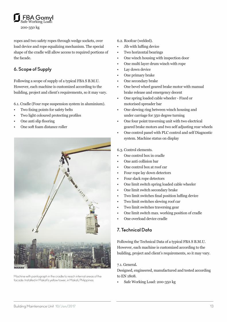
Machine with pantograph in the cradle to reach internal areas of the facade. Installed in Makati’s yellow tower, in Makati, Philippines.
Building Maintenance Unit 10/Jan/2017 14
• Hoisiting height: 0-300 m• Wheel gauge: 600-3000 mm• Wheel base: 600-3000 mm• Outreach max.: 30 m
7.2. Cradle.• Length: 2000-9000 mm• Width: 600 mm• Height: 1000/1200 mm
7.3. Ropes.• Nominal diameter: 8 mm• Number of ropes: 4• Construction: 114 wires - seale similar DIN 3058• Calculated breaking load: 44,40 kN• Min. breaking load: 38,20 kN• Calculated weight: 0,234 kg/m• Copper conductor: 0,96 mm2
• Safety factor min: 14• Tensile grade of wire: 1770 N/mm2
7.4. Material selection / corrosion protection.• Roofcar: RSt 37 - 2 hot dip galvanized• Undercarriage: RSt 37 - 2 hot dip galvanized• Jib: RSt 37 - 2 hot dip galvanized• Cradle: Aluminum• Exterior bolts and nuts: Austennitic stainless steel• High tensile bolts: HT - material, hot dip galvanized• Paint: 2 x 40 µm. Color code according to customer’s
specification
7.5. Electrical equipment.• Voltage: 380 Volt (others on request)• Frequency: 50 Hz (others on request)• Power supply: 3 Phase + PE + N• Hoisting drive: Bevel wheel geared brake motor with
manual brake release and emergency decent 1 x 2,2 KW• Actuator slew ring: Bevel wheel geared brake motor
with manual brake release 1 x 0,55 KW• Actuator traversing: Geared motor 2 x 0,25KW• Actuator luffing device: Hydraulicpump 0,55 KW
7.6. Power supply roofcar.• Power supply: Spring loaded cable drum 5 x 2,5 mm2
• Length: 25 m• Max. distance: 2 x 20 m
7.6. Control panel.• Protection: IP 55• Wattage: 3,5 KW• Supply rating: 20 Ampere
7.8. Controls.• Roofcar: Single maneuver selector with display. Start
up push button and emergency stop push button• Cradle: Single maneuver selector with display. Start up
push button and emergency stop push button• Signal transmission: Copper conductors in wire rope• Control voltage: 42V
8. Accesories / Optional Extras
The machine can be equipped with additional accesories as per project requirements:• 30 l Watertank in cradle • Material hoist 350 kg (others on request)• Soft starting motors• Facade Restraints (buildings in Excess of 40 m)
Some projects may require specific accesories which can be added as per client’s requirements.
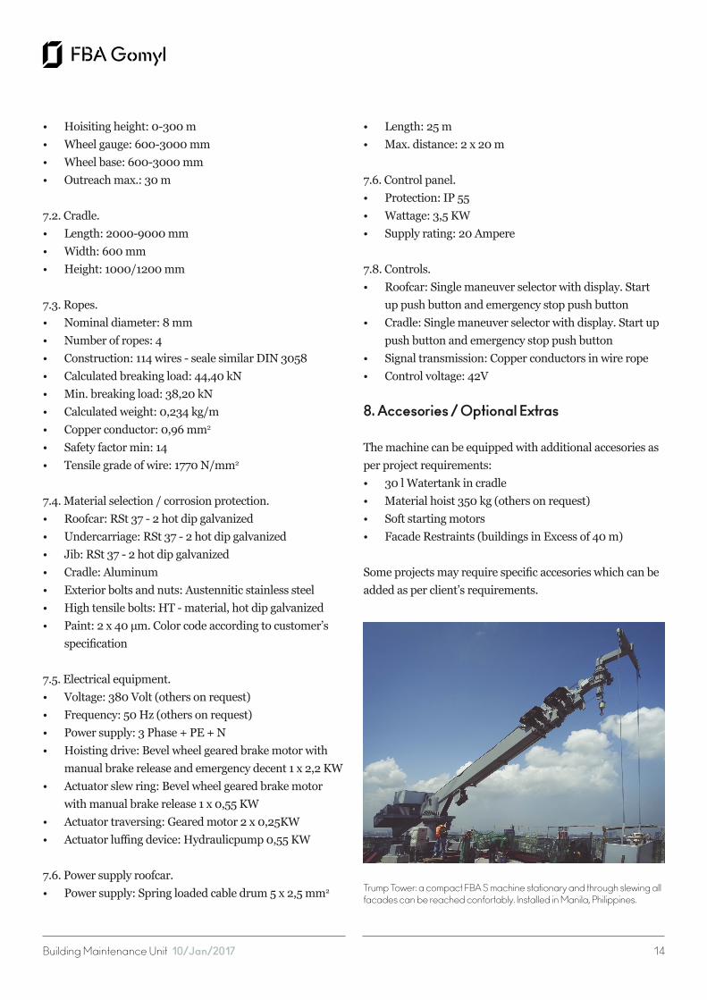
Trump Tower: a compact FBA S machine stationary and through slewing all facades can be reached confortably. Installed in Manila, Philippines.