building maintenance units blockstop minifor
TRANSCRIPT
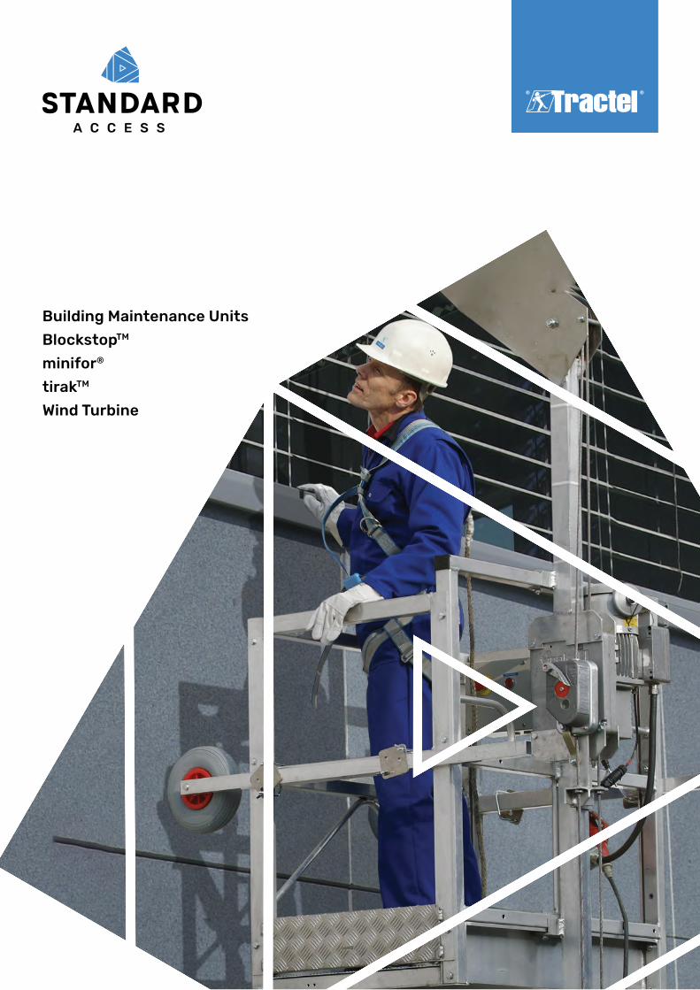
Building Maintenance Units
BlockstopTM
minifor®
tirakTM
Wind Turbine
Building Maintenance Units
STANDARD ACCESS | BUILDING MAINTENANCE UNITS
3
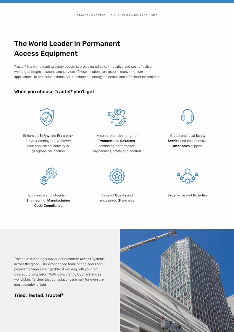
The World Leader in Permanent Access Equipment
Tractel® is a world leading safety specialist providing reliable, innovative and cost-effective working-at-height solutions and services. These solutions are used in many end-user applications, in particular in industrial, construction, energy, telecoms and infrastructure projects.
When you choose Tractel® you'll get:
Tractel® is a leading supplier of Permanent Access Systems across the globe. Our experienced team of engineers and project managers are capable of working with you from concept to installation. With more than 10,000 references worldwide, it's clear that our solutions are built for even the most complex of jobs.
Tried, Tested, Tractel®
Enhanced Safety and Protection for your employees, whatever your application, industry or
geographical location
Excellence and integrity in Engineering, Manufacturing
Code Compliance
A comprehensive range of Products and Solutions, combining performance,
ergonomics, safety and comfort
Assured Quality and recognized Standards
Global and local Sales, Service and cost effective
After-sales support
Experience and Expertise

STANDARD ACCESS | BUILDING MAINTENANCE UNITS
4
HMI LCD Display
HMI LCD display clearly communicates status of the BMU and platform to operator on platform and to the team on the rooftop.
Ergonomic Human Machine Interface (HMI)
The control system is equipped with dedicated failsafe toggle switches. User friendly design with dedicated switches for each function that eliminates unintentional machine movement.
tirak®: The Global Standard in Man-Riding Hoists
Dual driven tirak®has self-powered reelers that automatically collect the wire rope at the same speed as the hoist without the need to add motors, clutches and circuits.
Because the dual reelers do not collect the wire rope under load, we eliminate crushing and strand damage and prolong the lifespan of the wire rope.
BMU Standard Features
Built in safety devices constantly monitor all operations for complete operator safety. Integrated safety features include obstruction sensing device, overload detection, centrifugal brake, electromagnetic motor brake and in the event of loss of power, a manual controlled descent device.
Material hoist can be incorporated into the design for building maintenance or final construction.
Smooth Boom Transition
Rack and pinion driven boom with side rollers for smoother extention and retraction. Shown with hydraulic option when luffing, feature is used with extendable booms.

STANDARD ACCESS | BUILDING MAINTENANCE UNITS
5
Soft Start / Soft Stop Smoother ride providing precise platform positioning.
Dynamic Automatic Platform Leveling Ensures that the platform stays level during ascent or descent providing comfort, reassurance and safety. Continuous leveling eliminates the need for manual adjustment by service techs.
Anti-Tilt tracmod® Platform Dynamic automatic platform leveling, no need for manual adjustment. Sensor prevents platform from becoming unlevel ensuring comfort, reassurance and safety.
Inclined Track Option Shown on standard I-beam track, options available for inclined track or stationary BMUs.
BMU References
BMU with Self-Powered Platform
Material Hoist at Boom Tip
Track Mounted Retrofit
Luffing and Telescoping Mast
Parked Position
Stick Built - Retrofit
Track Mounted
tracmod® Extendable Platform
Transfer Shunt Carriage
Telescoping Mast
Articulating Platform
Luffing

BlocstopTM
7
STANDARD ACCESS | BLOCSTOPTM
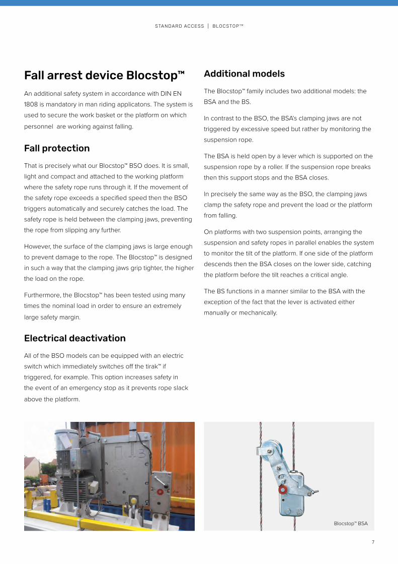
Fall arrest device Blocstop™An additional safety system in accordance with DIN EN 1808 is mandatory in man riding applicatons. The system is used to secure the work basket or the platform on which
personnel are working against falling.
Fall protection
That is precisely what our Blocstop™ BSO does. It is small, light and compact and attached to the working platform where the safety rope runs through it. If the movement of the safety rope exceeds a specified speed then the BSO triggers automatically and securely catches the load. The safety rope is held between the clamping jaws, preventing the rope from slipping any further.
However, the surface of the clamping jaws is large enough to prevent damage to the rope. The Blocstop™ is designed in such a way that the clamping jaws grip tighter, the higher the load on the rope.
Furthermore, the Blocstop™ has been tested using many times the nominal load in order to ensure an extremely
large safety margin.
Electrical deactivation
All of the BSO models can be equipped with an electric switch which immediately switches off the tirak™ if triggered, for example. This option increases safety in the event of an emergency stop as it prevents rope slack
above the platform.
Additional models
The Blocstop™ family includes two additional models: the BSA and the BS.
In contrast to the BSO, the BSA‘s clamping jaws are not triggered by excessive speed but rather by monitoring the suspension rope.
The BSA is held open by a lever which is supported on the suspension rope by a roller. If the suspension rope breaks then this support stops and the BSA closes.
In precisely the same way as the BSO, the clamping jaws clamp the safety rope and prevent the load or the platform from falling.
On platforms with two suspension points, arranging the suspension and safety ropes in parallel enables the system to monitor the tilt of the platform. If one side of the platform descends then the BSA closes on the lower side, catching the platform before the tilt reaches a critical angle.
The BS functions in a manner similar to the BSA with the exception of the fact that the lever is activated either manually or mechanically.
Blocstop™ BSA

8
STANDARD ACCESS | BLOCSTOPTM
ModelWLL in t Rope Specification
Bolt 0 in mmMan Riding Material
Handling0 in mm Min breaking
load in kN
BSO 510 - 0,35 6 13,7
12
BSO 500 0,6 0,6 8 47,1
BSO 520 0,6 0,6 9 47,1
BSO 1000 0,7 0,7 8 54,9
BSO 1020 0,8 0,8 9 62,8
BSO 1030 1,0 1,0 10 78,5
BSO 1040 1,0 1,0 11,5 78,5
BSO 2050 2,0 2,6 14 157,022
BSO 2360 2,3 3,0 16 180,5
BSO 500 - 510 - 520 BSO 1000 - 1020 - 1030 BSO 2050 - 3060

minifor®

10
STANDARD ACCESS | MINIFOR®
minifor® TR 10 - TR 30With its simple and efficient design, the minifor range makes it easy for you to choose the right hoist for your applications.
These two versions give you:
• unlimited length of hoist cable, adapted to the requirement
• light, easy to handle aluminium alloy design• integral handle for easy carrying• suitable for building sites, fast setup• efficient operation with swivelling suspension hook• extremely good weight/power ratio• reduced maintenance• quiet operation (70 dB)• operational safety : • upper and lower limit switches • brake motor • pendant control with emergency stop • CE socket
Conform to European directive no. 89/392 - 91/368 - 93/44 - 93/68 - 89/336 and to standards EN 50 081-2 and 50 082-2.
Options :
• Spring cable reel, capacity 20 m and 40 m• 9m/min 3-phase version, 48 VAC control, 0.55 kW motor
(TR30 only) - diagram n°1• Special motors• Long power supply and remote control cables• Pulley block kit - diagram n°2• Self-locking hook• Radio remote control with «lift/lower» function
Model Unit TR 10 TR 30
Hoisting capacity kg 100 300
Hoisting Speed m/min 15 5 single ph. 9-3 phase
Weight of Hoist kg 20 20.2
Dimensions mm mm5 355 x 420 x 180 Cable diameter
Cable weight (per m)
kg 0.105
Motor power Single phase 3-phase
kW kW
0.37 0.55
Cable breaking load factor 5
kg 1500
Power Supply Single 3-phase
115 V - 50 & 60 Hz - 230 - 50 Hz
230 - 400 V - 50 Hz
Operating factor % 40
Double insulated control pendant
IP 65 - 3 controls
Degree of protection
IP 55
Current with brake motor
A 7.5 at 115 V - 50 Hz single phase 9 at 115 V - 60 Hz single phase 4 at 230 V - 50 Hz single phase
1.8 at 400 V - 50 Hz 3-phase
1. Direct traction 2. Double tackle pulley block
11
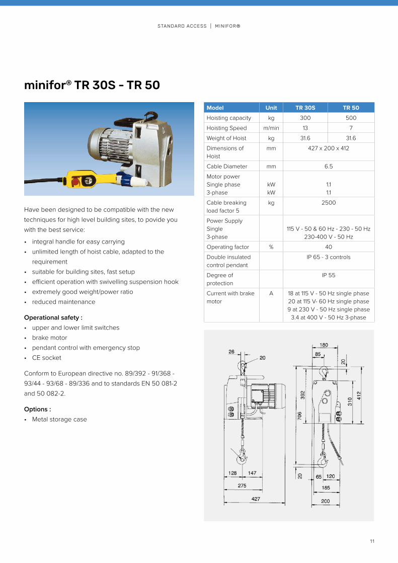
minifor® TR 30S - TR 50
Model Unit TR 30S TR 50
Hoisting capacity kg 300 500
Hoisting Speed m/min 13 7
Weight of Hoist kg 31.6 31.6
Dimensions of Hoist
mm 427 x 200 x 412
Cable Diameter mm 6.5
Motor power Single phase 3-phase
kW kW
1.1 1.1
Cable breaking load factor 5
kg 2500
Power Supply Single 3-phase
115 V - 50 & 60 Hz - 230 - 50 Hz
230-400 V - 50 Hz
Operating factor % 40
Double insulated control pendant
IP 65 - 3 controls
Degree of protection
IP 55
Current with brake motor
A 18 at 115 V - 50 Hz single phase 20 at 115 V- 60 Hz single phase 9 at 230 V - 50 Hz single phase
3.4 at 400 V - 50 Hz 3-phase
Have been designed to be compatible with the new techniques for high level building sites, to povide you with the best service:
• integral handle for easy carrying• unlimited length of hoist cable, adapted to the
requirement• suitable for building sites, fast setup• efficient operation with swivelling suspension hook• extremely good weight/power ratio• reduced maintenance
Operational safety :• upper and lower limit switches• brake motor• pendant control with emergency stop• CE socket
Conform to European directive no. 89/392 - 91/368 - 93/44 - 93/68 - 89/336 and to standards EN 50 081-2 and 50 082-2.
Options :• Metal storage case
STANDARD ACCESS | MINIFOR®

tirakTM

13
tirak™The tirak™ is a traction hoist – it drives the rope without reeling it in. For you, this means: You can lift and pull as far or as high as you want.
Thanks to the tirak™ rope pass-through design, unlimited rope lengths are theoretically possible, making the tirak™ a flexible option for every application.
With the tirak™ you can "climb upwards" with one rope for as far as you have to. This is why it is frequently used as a drive for man riding, as a single-person work seat and also for suspended platforms on famous high-rise buildings throughout the world.
The T-series
The T series is the first model in the tirak™ range and works with two traction sheaves. The wire rope runs through the two traction sheaves along an S-shaped path. The symmetrical design of the T-series makes these the only models capable of pulling in both directions with the same force. As such, they are ideal for use in all horizontal tasks where loads need to be moved back and forth.
The X-series
The X-series models use a single traction sheave to move the rope. The rope runs through a fittingly-sized groove in the traction sheave and is also pressed into place by means of a press system. This further increases the true load-bearing capacity to ensure even greater safety. At a particular point on the traction sheave the incoming and outgoing ropes cross over, lending the X series its name.
Using this functional principle, all of the models achieve a steady and constant rope speed; regardless of the position of the load.
Top quality
The tirak™ combines proven technology with modern developments and stateof-the-art production methods in order to achieve high standards of quality.
Development and production – Made in Germany.
Durable and powerful, yet nevertheless easy to transport, the tirak™ hoist provides the highest levels of reliability and dependability even in demanding environments, such as the harsh conditions on construction sites. This is why the tirak™ has now become the No. 1 motorized traction hoist worldwide.
Efficiency
Two decisive reasons for this success are the following profitability arguments:
1. Through the single rope drive, almost no maintenance costs are incurred beyond the mandatory safety inspections.
2. The extremely gentle rope drive ensures that the rope has a long service life.
Safety
Numerous details ensure the greatest possible safety when using the tirak™. All of the relevant standards and safety regulations are taken into account during development.
All tirak™ systems intended for man riding are equipped with integrated overload protection which reliably shuts down the tirak™ in the event of overloading.
The highest safety standards apply when man riding. Certified to EN1808 by an independent testing authority, the tirak™ hoist fulfils all of these requirements.
STANDARD ACCESS | T IRAKTM

14
STANDARD ACCESS | T IRAKTM
tirak™ for Man Riding
Universal Use
The tirak™ hoist is the ideal and universal option for man riding.
The compact dimensions and low weight enable easy handling and simplify the integration of the tirak™ hoist into the company‘s own applications, thus increasing productivity and efficiency.
The low weight of the tirak™ permits the system to have a higher payload. A complete series of tirak™ models offers load capacities from below 300 kg up to 2,000 kg for man riding.
This saves you a lot of time – and, of course, saves you money too!
Application
The tirak™ hoist can either be attached to a fixed mounting in order to pull the load on the wire rope or the rope is fixed and the tirak™ moves along the rope with the load. A wide range of accessories is available for attaching the tirak™ or the load, to suit the requirements of your application.
If the tirak™ utilizes a fixed mounting then deflection rollers can be used to guide or reeve the rope. So that the right tirak™ solution can be found for every task.
tirak™ for Material Handling
Versatility
Of course, the tirak™ is not only restricted to man riding. Its special advantages are: long weight, compact shape, unlimited rope length.
Enable easy handling and simplify the integration of the tirak™ hoist into the company‘s own applications, thus increasing productivity and efficiency.
A complete series of tirak™models offers load capacities from below 300 kg up to 3000 kg for material handling.
Possibilities
Three forms of application offer plenty of scope for the use of the tirak™:
1. tirak™ over the load
2. tirak™ anchored "within easy reach" – whereby this is a very broad term given the open length of the rope. Only a pulley needs to be fixed at the upper position. This simplifies preparation and saves lots of time.
Work basket for assembly work.
Work seat during repair work.
3. There is an even quicker method if you wish to hoist through the opening in a load-bearing wall/ceiling: Simply place the tirak™ behind or on top of it.
However, here the use of a mobile hoist is recommended with the tirak™.

tirak™ Mobile Hoists
They are the logical supplement to the tirak™ series.
tirak™ hoists can be equipped with a mobile frame in order to provide them with better protection against day-to-day damage or for easier transport.
This simplifies the handling of larger hoists or models fitted with a wire rope reeler, in particular, and reliably protects the tirak™ against hard impacts. A separate wire rope reeler can also be integrated into the frame if especially long ropes need to be wound up or stored.
Wire rope reeler
Thanks to the rope pass-through design of the tirak™ a wire rope reeler is not absolutely essential. The free end of the rope can simply be left hanging.
If you would prefer not to, three different types of rope reelers are available:
• The simplest solution consists of mounting a free reeler on the tirak™ into which the wire rope is fed. The rigidity of the wire rope causes it to wind and unwind automatically.
• When used with longer rope lengths, the rope reeler is driven by an extended traction sheave shaft. Ropes of up to several hundred metres in length can be stored economically on the tirak™. This also enables simple transportation.
• A separately driven rope reeler in a frame is utilized for even longer rope lengths. On mobile tirak™ systems this reeler is integrated into the frame, creating a single unit.
Free running reeler Separately driven wire rope reeler Driven wire rope reeler
15
STANDARD ACCESS | T IRAKTM
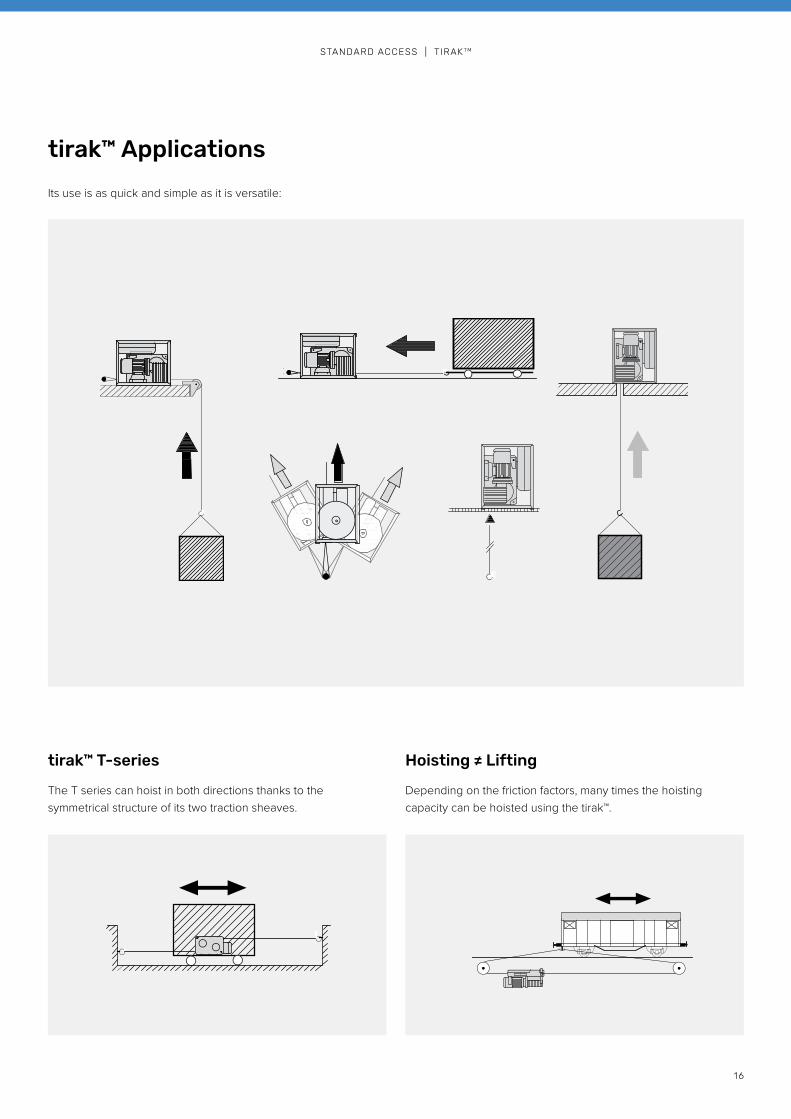
tirak™ Applications
Its use is as quick and simple as it is versatile:
tirak™ T-series
The T series can hoist in both directions thanks to the symmetrical structure of its two traction sheaves.
Hoisting ≠ Lifting
Depending on the friction factors, many times the hoisting capacity can be hoisted using the tirak™.
16
STANDARD ACCESS | T IRAKTM

Technical Specifications
* Drive types: 3 Ph = Three-phase motor, 1 Ph = AC motor (single phase)
*Reeler only available for listed tirak™
Working Speeds (m/min)
Optional wire rope reelers for material handling & man-riding*
Drive types* for X 2000 / 3000
50 Hz 60 Hz 50 Hz 60 Hz
0 = 3 Ph 9 11 6 7
or pneumatic drive or hydraulic drive
2 = 3 Ph 18 22 12 14
3 = 3 Ph 9/18 11/22 6/12 7/14
4 = 3 Ph 4,5 5,5 4,5 5,5
5 = 3 Ph 4,5/9 5,5/11 3/6 3,5/7
6 = 3 Ph 4,5/18 5,5/22 3/12 3,5/14
7 = 3 Ph stepless (0 to 9 / 18 / 30)
1 = 1 Ph 9 11 - -
Overview Free running wire rope reeler (Rope length) 1)(on request) not recommended
for every applications
Single reeler GM = triggered by a separate gearmotor
op. GM = optional triggering with gearmotor Other tirak™ are directly triggered by the tirak™ shaft
(XXX m) = maximum usable length
tirakTM Ø Rope Capacity (kg)
Ø350 mm
Ø400 mm
Ø450 mm(1)
Ø600 mm
90m (Plastic) 120m (op. GM)
220m (op. GM)
320m (op. GM)
X 300 Ø 8mm 300 40m 60m - - 90m (75m) - - -
X 400 Ø 8mm 400 40m 60m - - 90m (75m) - - -
X 310 Ø 6mm 300 60m 80m - - 160m (140m) - - -
X 510 Ø 6mm 350 60m 80m - - 160m (140m) 200m (189m) 360m (341m) 520m (493m)
X 500 Ø 8mm 500 40m 60m 80m - 90m (75m) 120m (110m) 220m (205m) 320m (300m)
L 500 Ø 8mm 500 40m 60m - - - - - -
X 600 Ø 8mm 600 40m 60m 80m - 90m (75m) 120m (110m) 220m (205m) 320m (300m)
X 800 Ø 8mm 800 40m 60m 80m - 90m (75m) 120m (110m) 220m (205m) 320m (300m)
X 520 Ø 9mm 500 33m 50m 65m - 70m (55m) 95m (85m) 170m (155m) 250m (230m)
X 620 Ø 9mm 600 33m 50m 65m - 70m (55m) 95m (85m) 170m (155m) 250m (230m)
X 820 Ø 9mm 800 33m 50m 65m - 70m (55m) 95m (85m) 170m (155m) 250m (230m)
X 1020 Ø 9mm 980 33m 50m 65m - 70m (55m) 95m (85m) 170m (155m) 250m (230m)
X 1220 Ø 9mm 1250 33m 50m 65m - 70m (55m) 95m (85m) 170m (155m) 250m (230m)
X 1030 Ø 10mm 1000 27m 40m 55m - - 80m (70m) 150m (135m) 220m (200m)
X 1530 Ø 10mm 1500 27m 40m 55m - - 80m (70m) 150m (135m) 220m (200m)
X 2050 Ø 14mm 2000 - - 40m 110m - 55m (GM) 65m (GM) -
X 3050 Ø 14mm 3000 - - 40m 110m - 55m (GM) 65m (GM) -
X 300P Ø 8mm 300 40m 60m - - 90m (75m) - -
X 400P Ø 8mm 400 40m 60m - - 90m (75m) - - -
X 500P Ø 8mm 500 40m 60m 80m - 90m (75m) 120m (110m) 220m (205m) 320m (300m)
X 520P Ø 9mm 500 33m 50m 65m - 70m (55m) 95m (85m) 170m (155m) 250m (230m)
X 620P Ø 9mm 600 33m 50m 65m - 70m (55m) 95m (85m) 170m (155m) 250m (230m)
X 820P Ø 9mm 800 33m 50m 65m - 70m (55m) 95m (85m) 170m (155m) 250m (230m)
X 1030P Ø 10mm 1000 27m 40m 55m - - 80m (70m) 150m (135m) 220m (200m)
X 2050P Ø 14mm 2000 - - 40m 110m - 55m (GM) 65m (GM) -
17
STANDARD ACCESS | T IRAKTM

Technical Specifications
*Reeler only available for listed tirak™Optional wire rope reelers for mobile winches*
Overview Free running wire rope
reeler (Rope length)
Single reeler MW = Mobile Winch- in frame
GM = triggered by a separate gearmotor Other tirak™ are directly triggered by the tirak™ shaft
(XXX m) = maximum usable length
tirakTM Ø Rope Capacity (kg)
MW MW 120m
MW 220m
MW 300m GM
MW 500m
MW 800m GM
MW 1000m GM
X 510 Ø 6mm 350 80m 200m (189m) 360m (341m) - 820m (793m) - -
X 500 Ø 8mm 500 60m 120m (110m) 220m (205m) - 500m (480m) - 1000m (978m)
X 600 Ø 8mm 600 60m 120m (110m) 220m (205m) - 500m (480m) - 1000m (978m)
X 800 Ø 8mm 800 60m 120m (110m) 220m (205m) - 500m (480m) - 1000m (978m)
X 520 Ø 9mm 500 50m 95m (85m) 170m (155m) - 400m (380m) - 800m (780m)
X 620 Ø 9mm 600 50m 95m (85m) 170m (155m) - 400m (380m) - 800m (780m)
X 820 Ø 9mm 800 50m 95m (85m) 170m (155m) - 400m (380m) - 800m (780m)
X 1020 Ø 9mm 980 50m 95m (85m) 170m (155m) - 400m (380m) - 800m (780m)
X 1220 Ø 9mm 1250 50m 95m (85m) 170m (155m) - 400m (380m) - 800m (780m)
X 1030 Ø10mm 1000 40m 80m (70m) 150m (135m) - 350m (333m) - 700m (686m)
X 1530 Ø10mm 1500 40m 80m (70m) 150m (135m) - 350m (333m) - 700m (686m)
X 2050 Ø14mm 2000 40 / 110 m - - 300m (287m) - 800m (765m) -
X 3050 Ø14mm 3000 40 / 110 m - - 300m (287m) - 800m (765m) -
X 500P Ø 8mm 500 60m 120m (110m) 220m (205m) - 500m (480m) - 1000m (978m)
X 520P Ø 9mm 500 50m 95m (85m) 170m (155m) - 400m (380m) - 800m (780m)
X 620P Ø 9mm 600 50m 95m (85m) 170m (155m) - 400m (380m) - 800m (780m)
X 820P Ø 9mm 800 50m 95m (85m) 170m (155m) - 400m (380m) - 800m (780m)
X 1030P Ø10mm 1000 40m 95m (85m) 170m (155m) - 350m (333m) - 700m (686m)
X 2050P Ø14mm 2000 40 / 110 m - - 300m (287m) - 800m (765m) -
Double reeler MW = Mobile Winch- in frame
(XXX m) = maximum usable length
MW 2x120m MW 2x220m MW 2x320m
XD 300P Ø 8mm 350 2x120m (2x110m) 2x220m (2x205m) -
XD 310P Ø 6mm 350 2x200m (2x189m) 2x360m (2x341m) -
XD 500P Ø 8mm 500 2x120m (2x110m) 2x220m (2x205m) 2x320m (2x300m)
XD 800P Ø 8mm 800 2x120m (2x110m) 2x220m (2x205m) 2x320m (2x300m)
XD 720P Ø 9mm 700 2x95m (2x85m) 2x170m (2x155m) 2x250m (2x230m)
XD 820P Ø 9mm 800 2x95m (2x85m) 2x170m (2x155m) 2x250m (2x230m)
XD 1020P Ø 9mm 1000 2x95m (2x85m) 2x170m (2x155m) 2x250m (2x230m)
XD 1030P Ø 10mm 1000 2x80m (2x70m) 2x150m (2x135m) 2x220m (2x200m)
18
STANDARD ACCESS | T IRAKTM

Wind Turbine

Blade Maintenance Platform
Wind farms are becoming ever taller. Hardly surprisingly, since the higher the turbine rotors are positioned, the more likely they are to be within a constant air flow affording greater efficiency.
Of course, the height of the masts imposes very special requirements upon manufacturers and operating companies.
For external access to the wind turbine and in particular for inspection and maintenance of the rotor blades, suspended platforms are proving their superiority over other forms of access.
• Consistently low costs for assembly and dismantling due to minimum installation time irrespective of operating height.
• Independence from cranes or hoists for material transport.
• Time saving, as the suspended platform always offers an optimum working position.
• And last, but not least, there is no need for anchoring to the tower.
TECHNICAL DATA
Standard Platform Capacity (2 persons and material) Total : 300 kg
Per platform section : 150 kg Dead weight approx. : 1300 kg Other dimensions on request
20
STANDARD ACCESS | WIND TURBINE

Service Lift, rope or ladder-guided
For access within the masts, our service lift uses the wire rope driving principle of the Tirak™ Manriding hoists:
• It simply runs up and down the wire rope which is anchored at the top of the tower.
• The quite operating Tirak™ hoist is light weight and only requires a minimum of space.
• No unnecessary wire rope weight to reduce lift capacity.
• Standard use by two persons.
• Two options available: wire ropeguided or ladder-guided.
Safety features:
• Electrically monitored door for entrance as well as exit to and from the platform.
• Standard limit switches as well as additional safety limit stops above and below the service lift.
• Blocstop™ fall arrest device ensures that the service lift does not gain too much speed during travel , in the event of wire rope rupture breaking or simply to improve operational safety!
• In the event of a power failure, the service lift can be lowered using the emergency descent device.
Tirak™ Endless Hoist & Blocstop™ BSO Fall Arrest Device
Approved and CE-marked in accordance with EN 1808 for “Suspended Access Equipment”, the Tirak™ hoists for manriding applications offer capacities from 300 to 2000 kg and speeds of up to 18 m / min, ensuring fast access to the top, and, due to the continuously circulating wire rope, height is almost irrelevant.
Safety first!
The BlocstopTM fall arrest devices are used to protect loads against falling in case of wire rope rupture, or simply to improve operational safety.
The ladder-guided version offers several advantages:
• No additional parts are required for wire rope guidance.
• Direct access to the ladder by means of a second door and a lower trap door. All precautions have been taken for technical failures: lift entry and evacuation on failure, and correction is possible without any special prior preparations.
• Particularly low vibration and smooth running thanks to rollers.
21
STANDARD ACCESS | WIND TURBINE

Climbing Aid for Vertical Ladders
The Climbing Aid relieves persons climbing a ladder with a constant pulling force of approx. 40 daN (≈ 40 kg) and offers the following advantages:
• Less stress on arms and legs,
• Less physical exertion for the climber,
• Lower risk of accidents as exhaustion is effectively reduced, significantly improving operational safety.
Drive and Control
A gear motor at the lower end of the ladder drives the looped belt by means of a drive pulley.
The pulley is connected to the gearbox by a continuously adjustable, oil-bathlubricated sliding clutch.
The continuous welded, reinforced round belt, made of special synthetic material, runs over the drive pulley and the diverter pulley at the upper end of the ladder.
Approved system:
The motor is automatically turned on or off by a switch signal which monitors the revolution of the drive pulley:
• At the fi rst switch signal, e. g. when pulling the round belt upwards, the motor starts and keeps running, as long as the signal is repeated within three seconds.
• If the round belt’s movement is stopped, e.g. by interrupting the ascent, the signal is not repeated within a three-second interval and the motor stops.
Connection to the round belt
The harness (EN 361) is connected to the round belt by a rope grab (EN 567) with a spring snap connector (EN 362). The immediate connection is to the D-ring at chest level.
The removable driver unit
One motor for any number of Climbing Aids – that is the economic solution, where neighbouring installations are not all used at the same time, as is the case in wind farms.
Universal application
Driver unit and diverter pulley are also available for standard ladders (Fig. 1 + 3), for ladders with a middle pole (Fig. 4 + 5) as well as for those with round rungs (Fig. 3).
Advantage: no need for additional control such as a pull cord or similar, which excludes potential sources of error.
FIG. 1 FIG. 2 FIG. 4FIG. 3 FIG. 5
22
STANDARD ACCESS | WIND TURBINE

Height Safety Equipment
When working at height, safety is the primary concern at all times. Our range offers all the appropriate equipment for the access, working and potential rescue situations that personnel are likely to encounter in wind power plants.
• Comfortable, fully equipped fall arrest, work positioning and sit harnesses.
• Web or rope lanyards with shock absorber.
• Derope™ Descender and Rescue Lifting Devices. Constant speed of approx. 42 m / min., descent height of up to 400 m for one and 125 m for two persons.
• Blocfor™ Retractable Lifelines and Rescue Lifting Devices. Available with synthetic rope to avoid damage to varnished surfaces and glass-fi bre parts of the construction.
• Stopfor™ Rope Grabs on polyamide or kernmantel rope for restraint or fall arrest use.
• Temporary and permanent anchor points to attach the fall arrest system.
• Connectors, scaffolding hooks and accessories.
• Work positioning and restraint lanyards.
• Height safety kits for the most frequently encountered working situations, including bag or box for transport and storage.
TrainingThe Tractel Group‘s worldwide network of companies offer height safety training and can provide on-site product and rescue training.
Engineering SolutionsOur engineering team is closely involved in all aspects of project management, bringing a high degree of effi ciency and responsiveness to our services. Our knowledgeable professionals will work with you to develop engineering solutions to meet all your wind energy application needs.
Material Hoist with Textile Rope
The material hoist with textile rope has been specially designed to lift loads on wind turbines. Using through rope technology, it is an electric, portable hoist that is lightweight, compact and has a wide range of applications on the work site.
The flexibility and light weight of the textile rope offer many advantages:
• Easy handling even over lifting heights of up to 150 m.
• No damage to surfaces which come into contact with the rope.
• Smaller bending radii possible.
The uses vary according to the type of wind turbines, electric pylons and construction sites.
23
STANDARD ACCESS | WIND TURBINE
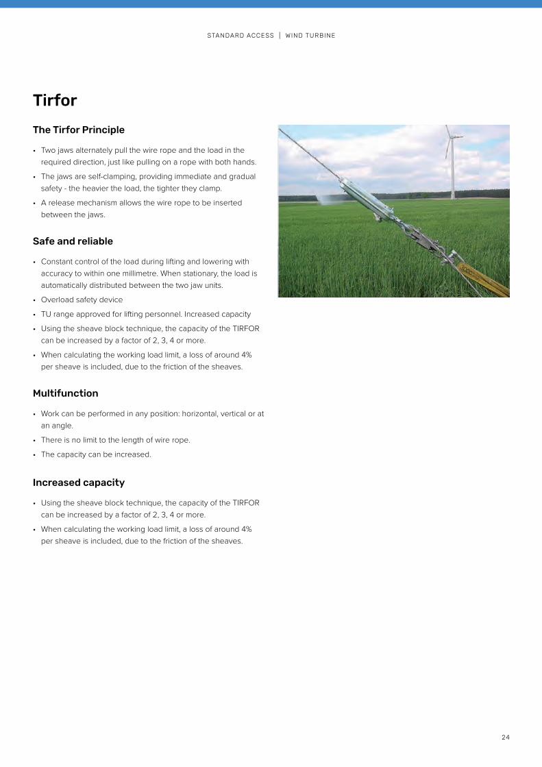
Tirfor
The Tirfor Principle
• Two jaws alternately pull the wire rope and the load in the required direction, just like pulling on a rope with both hands.
• The jaws are self-clamping, providing immediate and gradual safety - the heavier the load, the tighter they clamp.
• A release mechanism allows the wire rope to be inserted between the jaws.
Safe and reliable
• Constant control of the load during lifting and lowering with accuracy to within one millimetre. When stationary, the load is automatically distributed between the two jaw units.
• Overload safety device
• TU range approved for lifting personnel. Increased capacity
• Using the sheave block technique, the capacity of the TIRFOR can be increased by a factor of 2, 3, 4 or more.
• When calculating the working load limit, a loss of around 4% per sheave is included, due to the friction of the sheaves.
Multifunction
• Work can be performed in any position: horizontal, vertical or at an angle.
• There is no limit to the length of wire rope.
• The capacity can be increased.
Increased capacity
• Using the sheave block technique, the capacity of the TIRFOR can be increased by a factor of 2, 3, 4 or more.
• When calculating the working load limit, a loss of around 4% per sheave is included, due to the friction of the sheaves.
24
STANDARD ACCESS | WIND TURBINE

43 Dunmore Drive, Truganina VIC 3029 Australia
+61 3 9116 4090 [email protected] www.standardaccess.com.au