building structure design of the sunan hotel 7 … · published, namely sni-1726:2012 (tata cara...
TRANSCRIPT
BUILDING STRUCTURE DESIGN OF
THE SUNAN HOTEL 7 (SEVEN) FLOORS AND 1 (ONE) BASEMENT
USING INTERMEDIATE MOMENT RESISTING FRAME (IMRF) IN
SURAKARTA
Final Project to Achieve a Part of
Civil Engineering Bachelor Degree Requirement
submitted by :
M. BAGUS RIZAL RIYANANSYAH
D 100 134 007
ENGINEERING FACULTY
CIVIL ENGINEERING DEPARTMENT
UNIVERSITAS MUHAMMADIYAH SURAKARTA
2017

i

ii

1
BUILDING STRUCTURE DESIGN OF
THE SUNAN HOTEL 7 (SEVEN) FLOORS AND 1 (ONE) BASEMENT
USING INTERMEDIATE MOMENT RESISTING FRAME (IMRF)
IN SURAKARTA
Abstraction
Surakarta city located on the southern island of Java, Central Java Province, Indonesia.
Surakarta city become tourist attraction for foreign and national to visit. These conditions will
grow especially on the perspective of business. Infrastructure needs in the city of Surakarta
will increase the coming of the tourists or people who have a purpose in coming different. The
supporting infrastructure like as the construction site hotel. Therefore it, would planned
building structure design of The Sunan hotel 7 (seven) floors and 1 (one) basement using
intermediate moment resisting frame (IMRF) in Surakarta.Which should be considered in the
planning of the building structure including safety aspects, architectural and economic.
Planning the hotels building refers to the regulation standards (SNI) version that has been
published, namely SNI-1726:2012 (Tata Cara Perencanaan Ketahanan Gempa Untuk Struktur
Gedung dan Non-Gedung) and SNI 2847:2013 (Persyaratan Beton Struktural Untuk
Bangunan Gedung). The building plan includes a main structure (the structure of columns,
beams, and under the structure) and the steel roof structure and a slab structure (slab floors,
staircases and basement). The location of the building in the city of Solo and the ground site
including SD classification (ground medium), then the SDS and SD1 values obtained are 0,599g
and 0,370g. For planning of earthquake loads on the building needs sway intermediate (SI),
used primacy building factor 1 (for building hotel are included in category II), response
modification factor (R) equal to 5, the method of analysis earthquake load using the static
equivalent. Quality of concrete used f'c 25 MPa, and the quality of reinforcement use fy 390
MPa and for shear reinforcement use fy 240 MPa. Dimensional beam structure planned
500/700 mm for the 1st to 4th floors, and 450/600 mm for the 5th floor to the roof. As for the
column is planned with the dimensions 750/850 mm to all the floors. Under the structure of
pile foundation planned diameter to use 400 mm with a depth total is 18 m, and dimensions of
pile cap first type is 1500x1500x750 mm for pile foundation 5 piles, the second type is
3200x3200x750 mm for pile foundation 9 piles and the third type is 3200x2100x750 mm for
pile foundation 9 piles. Sloof planned dimension 350/700 mm.
Keywords: building structure, intermediate moment resisting frame, planning.

2
Abstrak
Kota Surakarta terletak di sebelah selatan Pulau Jawa, Propinsi Jawa Tengah, Indonesia. Kota
Surakarta menjadi objek wisata bagi wisatawan asing dan nasional untuk dikunjungi. Kondisi
ini akan tumbuh terutama pada perspektif bisnis. Kebutuhan infrastruktur di kota Surakarta
akan meningkatkan datangnya wisatawan atau orang yang memiliki tujuan datang berbeda.
Infrastruktur pendukungnya seperti konstruksi hotel. Oleh karena itu, maka direncanakan
struktur bangunan hotel The Sunan 7 (tujuh) lantai dan 1 (satu) basement menggunakan
sistem rangka pemikul moment menengah (SRPMM) di Surakarta. Struktur gedung yang
direncanakan harus mempertimbangkan aspek keamanan, arsitektural dan ekonomi.
Perencanaan gedung hotel ini mengacu pada standar peraturan (SNI) terbaru yang telah
diterbitkan, yaitu SNI-1726:2012 (Tata Cara Perencanaan Ketahanan Gempa Untuk Struktur
Gedung dan Non-Gedung) dan SNI-2847:2013 (Persyaratan Beton Struktural Untuk
Bangunan Gedung). Perencanaan gedung ini mencakup struktur utama (struktur atas
balok,kolom dan struktur bawah) serta struktur rangka atap baja dan struktur plat (plat lantai,
dinding basement dan tangga). Lokasi bangunan di wilayah kota Solo dan perhitungan
klasifikasi situs tanah termasuk kategori SD (tanah sedang), maka diperoleh nilai SDS dan SD1
adalah 0,599g dan,370g. Untuk kebutuhan perencanaan beban gempa pada gedung dengan
SRPMM, dipakai faktor keutamaan bangunan Ie dengan nilai 1,0 (hunian, kategori risiko II)
faktor modifikasi respons (R) sebesar 5, metode analisis beban gempa menggunakan statik
ekivalen. Mutu beton yang dipakai fc’ 25 MPa, serta mutu tulangan baja ulir fy 390 MPa dan
tulangan geser polos fy 240 MPa. Struktur balok direncanakan berdimensi 500/700 mm untuk
lantai 1 sampai 4, dan 450/600 mm untuk lantai 5 sampai atap. Sedangkan untuk kolom
direncanakan dengan dimensi 750/850 mm untuk untuk semua lantai. Struktur bawah
direncanakan memakai pondasi tiang pancang diameter 400 mm dengan kedalaman total 18
m, dengan dimensi poer tipe pertama 1500x1500x750 mm untuk pondasi tiang pancang 5
tiang, tipe kedua adalah 3200x320x750 mm untuk pondasi tiang pancang 9 tiang dan tipe
ketiga adalah 3200x2100x750 mm untuk pondasi tiang pancang 5 tiang.Sloof direncanakan
berdimensi 350/700 mm.
Kata Kunci : perencanaan, sistem rangka pemikul momen menengah, struktur gedung.

3
1. PRELEMINARY
1.1. Background
Surakarta city located on the southern island of Java, Central Java Province, Indonesia.
Surakarta city become tourist attraction for foreign and national to visit. These conditions will
grow especially on the perspective of business. Infrastructure needs in the city of Surakarta
will increase the coming of the tourists or people who have a purpose in coming different. The
supporting infrastructure like as the construction site hotel. Therefore it, would planned
building structure design of The Sunan hotel 7 (seven) floors and 1 (one) basement using
intermediate moment resisting frame (IMRF) in Surakarta. Which should be considered in the
planning of the building structure including safety aspects, architectural and economic.
Planning the hotels building refers to the regulation standards (SNI) version that has been
published, namely SNI-1726:2012 (Tata Cara Perencanaan Ketahanan Gempa Untuk
Struktur Gedung dan Non-Gedung) and SNI 2847:2013 (Persyaratan Beton Struktural Untuk
Bangunan Gedung).
1.2. Discussion of the Problems
According to background above, so the discussion problems that can be taken is how
plan structure the hotel building 7 (seven) floors and 1 (one) basement using Intermediate
Moment Resisting Frame (IRMF) in Surakarta that efficient in accordance with the latest
Indonesia National Standard ?
1.3. Objectives and Benefits Planning
1.3.1. Planning objectives
Building structure design of the Sunan hotel 7 (seven) floors and 1(one) basement
using Intermediate Moment Resisting Frame (IRMF) in Surakarta have purpose to get the
design planning structure buildings safe and resistant to earthquake often happens in
indonesia. Calculation of structures that produce specifications and design drawings must also
can be accounted safety and strength based on the regulation apply in Indonesia.
1.3.2. Planning benefits
Benefit obtained from the author of the final project is knowing more about the
science of the structure, especially desingn prosses in good building to earthquake resistant
and efficient, mechanics analysis to design concrete reinforced. This final project can also be
4
used as a reference for readers in planning earthquake-resistant building structures efficiently
as needed.
1.4.Scope of the Problems
a) Building structure 7 (seven) floors and 1 (one) basement using Intermediate Moment
Resisting Frame (IRMF).
b) Calculation structure was about calculation analysis structure, calculation design slabs
and the walls of basement. The design stairs, calculation design beam, calculation
design column and calculation design foundation.
c) Construction lift is not planned.
1.5. Literature Review
1.5.1. Design concept of earthquake resistant building structure
1.5.1.1. The concept of earthquake resistant building based on the level of building
performance
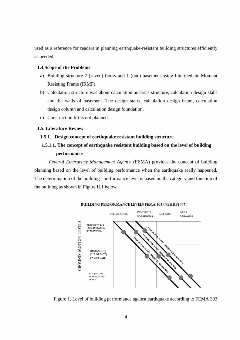
Federal Emergency Management Agency (FEMA) provides the concept of building
planning based on the level of building performance when the earthquake really happened.
The determination of the building's performance level is based on the category and function of
the building as shown in Figure II.1 below.
Figure 1. Level of building performance against earthquake according to FEMA 303

5
1.5.1.2. Concept design capacity
In planning the structure of earthquake resistant building should be applied concepts
Strong Column Weak Beam (SCWB). When an earthquake exceeds the plan earthquake, the
plastic hinge must occur on the beam first before it occurs on the column. The planned
structure with the SCWB concept needed many plastic hinge before collapse compare than
structures with the concept of "Strong Beam Weak Column". The usual frame building
structure planned with the SCWB concept is often called the Moment Resisting Frame System
(MRF) with the Medium Daktility level (IMRF) as well as with the special ductility (SMRF).
1.5.2. Load structure
1.5.2.1.Factor and combination load
Factors and combinations of charges are provided for in Article 4.2, as follows.
a). 1,4D (1)
b). 1,2D + 1,6L + 0,5(Lr or R) (2)
c). 1,2D + 1.6(Lr or R) + (L or 0.5W) (3)
d). 1,2D + 1,0W + L + 0,5(Lr or R) (4)
e). 0,9D + 1,0W (5)
f). (1,2+0,2SDS)D + ρ.E + L (6)
g). (0,9-0,2SDS)D + ρ.E (7)
With,
D = dead load,
` L = live load, Lr = live load on the roof
R = rain load
W = wind load
E = earthquake load
ρ = redundancy factor (The value 1,0 to1,3) (Article 7.3.4)
SDS =parameter of acceleration of short spectrum response
1.5.2.2. Strength reduction factor
Used to reduce the stiffness of the structure with consideration of the uncertainty of
the stiffness of structural elements due to imperfections on the field (Asroni:2010). The value
strength factor (Ø) in regulation SNI-2847-2013 Article 9.3

6
1.5.3. Earthquake load
1.5.3.1.Earthquake determinants
1.5.3.1.1. Factor primacy of building (Ie) and risk category of building structures
Article 4.1.2, the risk categories of building structures has 4 categories. Category I is a
category of buildings and non-buildings that have the lowest level of priority, while category
IV is the category with the highest priority of the building. The primacy factor of the building
is adjusted according to the risk category of the building structure. The higher the category of
building structure, then the value of the value factor is also higher.
1.5.3.1.2. The natural vibration period of the structure (T)
To calculate the natural vibration period, formulations used in SNI-1726-2012 Section
7.8.2.1 are specified for analysis by static methods, with must be controlled by the exact
vibration period.
1.5.3.1.3. Earthquake load coefficient (C)
The value C obtained from diagram spectrum response based on the natural vibration
period of the structure (T). The value C used as a base load for the shear force of the structure
design.
1.5.3.1.4. Earthquake load reduction factor(R)
The earthquake load reduction factor or the response modification factor (R) is a value
that reduces the amount of earthquake load based on the type of planned structure and other
supporting structural components. The value R be requlated in SNI-1726-2012 Article 7.2.1.
1.5.3.1.5. Effective seismic weight (W)
Effective seismic weight is its self weight of the whole structure with the reduced live
load weight. The seismic weight be requlated in SNI-1726-2012 Article 7.7.2.
1.5.3.2. Response spectrum in the region of Indonesia.
The spectrum responses of each region in Indonesia vary depending on location and
ground conditions. Spectrum response in the region of Indonesian be requlated in SNI-1726-
2012 Article 6. Here are the factors that influence the spectrum response of a region.
1.5.3.2.1. Parameters of short period acceleration response (SS) and a period of 1
second (S1)
SS and S1 parameters are obtained based on seismic maps inside SNI-1726-2012.
Acceleration response parameter of short period or 0,2 second (SS) and a period of 1 second

7
(S1) used because among these periods contain the largest earthquake energy.
1.5.3.2.2. Classification ground site (as an amplification factor)
In determining the status of the ground has be done ground investigation with depth of up
to 30 m. Characteristics of soil required is shear wave velocity (vs), standard penetration test
N-SPT (N) and shear strength ground (su). From 3 criteria minimum should be 2 criteria to
determine the status of the land. Site land is classified into 6 sites, ie SA up to SF.
1.5.3.2.3. Category of seismic design
In article 6.5, the structure should be assigned the Seismic Design Category based on
structural risk category, short period acceleration response parameter (SDS) and period of 1
second (SD1). Category of seismic design is divided into 6 categories (A - F). The higher the
group will have an impact on the regulation and detailing of the stricter structure.
1.6. Theorical Basic
1.6.1. Response spectrum diagram
Response spectrum diagram (Article 6) made coordinates by manual or website
puskim.go.id applications with ground classification data of the site (SA up to SF).
SDS = 2
3× 𝑠𝑚𝑠 × 𝑐𝑟𝑠 (8)
SD1 = 2
3× 𝑠𝑚1 × 𝑐𝑟𝑠1 (9)
Figure 2. Spectra Response Diagram

8
1.6.2. Modeling and load structure
In the SAP 2000 application, the frame structure is modeled with a 3D closed frame (floor
slabs modeling). The gravitational loads suffered by the structure will be modeled as an
envelope load (triangle or trapezoid) on each frame.
Figure 3. Modeling and Load Structure
1.6.3. Evaluation of structural irregularities
The building is designed to be evaluated against the irregularities horizontally and
vertically in Section 7.3.2.
The irregularities of this structure will have an impact on:
a) Whether or not the design of the structure is used (based on Category of seismic
design),
b) Static or dynamic analysis (Article 7.6).
1.6.4. Load earthquake on the structure
1.6.4.1. Equivalent Lateral Force analysis
Earthquake load with equivalent static method (equivalent lateral force, ELF) with
manual calculated and load pattern IBC 2009 from SAP 2000 application as shown in Figure
4. Earthquake loads on each floor with eccentricity of 5% plan from center of stiffness.

9
Figure 4. Earthquake Load ELF IBC 2009
1.6.4.2. Dynamic Response Spectrum analysis
Earthquake load can be calculated by the method of dynamic response of the spectrum
by taking into account the following criteria and requirements:
a). The number of modes used in the calculation has a mass participation accumulation of
at least 90% (Article 7.9.1).
b). Superposition mode uses the CQC (Complete Quadratic Combination) method if the
difference between the vibration period between modes is not more than 15%. If more
than that then used the method of SRSS (Square Root of the Sum of Sum Squares).
c). Dynamic earthquake loads must be scaled so that the acquired seismic dynamic shear
force of not less than 85% of earthquake static (ELF) (Section 7.9.4.1).
1.6.5. Response analysis and Drift control permission structure
Analysis of the structure's response is calculated by SAP applications 2000. The output
results need to be validated as required by a conventional method to ensure modeling and
loading structure is correct.
Drift every floor due to earthquake loading must be controlled with maximum permissible
drift. Drift floor (Article 7.8.6) calculated by the formula:

10
δx = 𝐶𝑑.δ𝑒
𝐼𝑒 (10)
with,
δx = floor drift to direction x
Cd = deflection enlargement factor
δx = floor drift calculation results
Ie = the primacy factor of the building
Drift (δx) the calculated floor should be reviewed from the structure response due to the
earthquake load with the original vibration period (without limitation Cu.Ta). δx should not
exceed Δpermission which is calculated by the formula:
Δ permission= 0,020.hsx, with hsx = high floor (11)
1.6.6. Design of reinforcement concrete structure
Frame structure is designed based on the needs forces of the frame by using the
principle IRMF with the concept of capacity design. Beam and column installed plastic hinge
the hope that the sway and collapse as planned. The plastic hinge on the beam installed
distance of 2h from the face of the column, while the plastic hinge of the column installed at
distance λo from the bottom of the foot of the column with the following conditions
λo ≥ 1/6 of the net height of the column
λo ≥ the largest dimension of column cross section
λo ≥ 500 mm.
1.6.7. Biaxial column control
Ability to withstand moments column 2 direction with bresler with formula :
a = (𝑀𝑢𝑥
𝑀𝑢𝑥𝑜)𝑚
+ (𝑀𝑢𝑦
𝑀𝑢𝑦𝑜)𝑛
(12)
1.6.8. Under structure design
The foundation is planned using pile foundation. The bearing capacity of the pile is
obtained from the frictional resistance (Qs) and the end resistance pile (Qb). Piles (can be
grouped with certain efficiency) are designed only to withstand axial loads. The reinforcement
on the piles has function to withstand the moment when the process implementation in the
field. Pile cap above the piles has function to withstand the moment that occurs due to load
eccentricity axial load piles with center point pile cap.
11
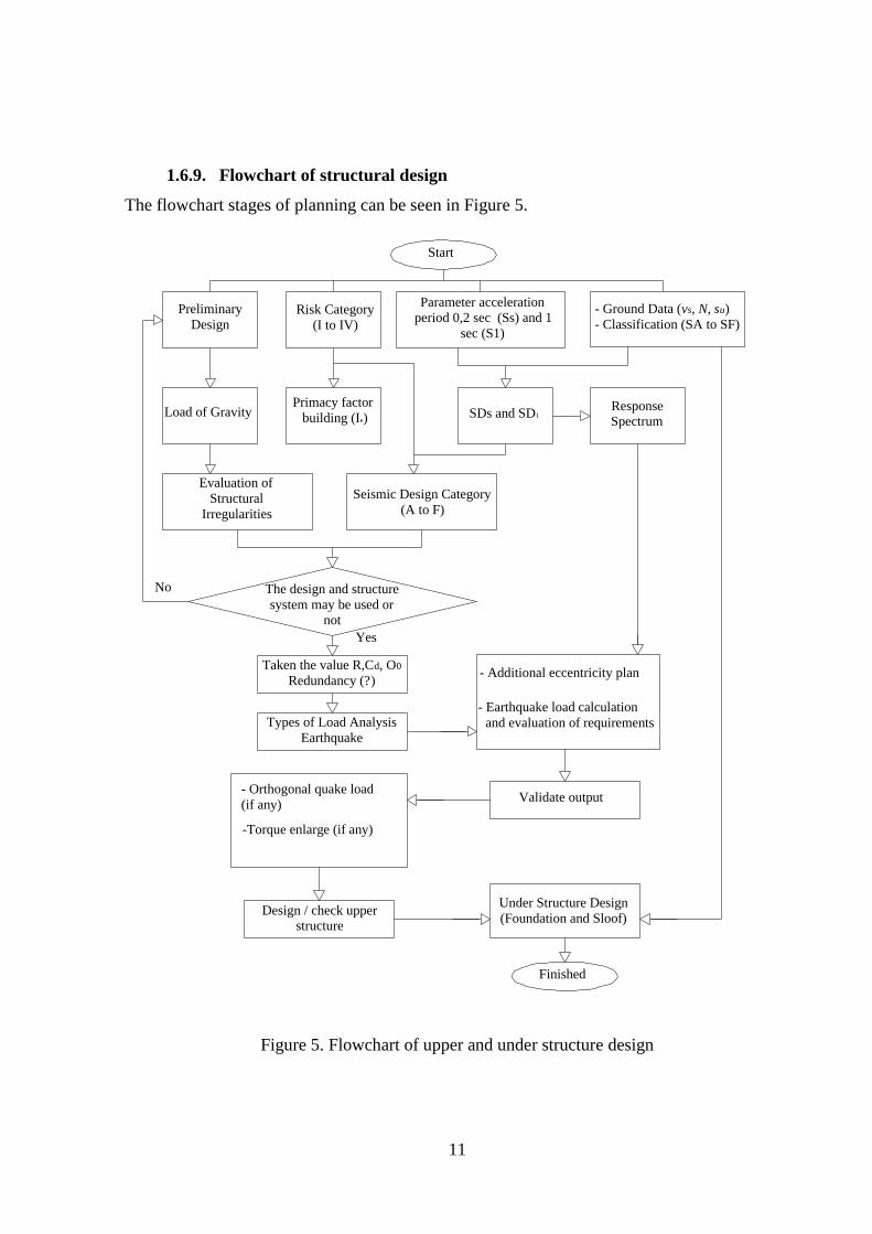
1.6.9. Flowchart of structural design
The flowchart stages of planning can be seen in Figure 5.
Preliminary
DesignRisk Category
(I to IV)
- Ground Data (vs, N, su)
- Classification (SA to SF)
Parameter acceleration
period 0,2 sec (Ss) and 1
sec (S1)
SDs and SD1
Primacy factor
building (Ie)Load of Gravity ResponseSpectrum
Evaluation of
Structural
Irregularities
Seismic Design Category
(A to F)
The design and structure
system may be used ornot
No
Taken the value R,Cd, O0
Redundancy (?)
Types of Load Analysis
Earthquake
- Additional eccentricity plan
- Earthquake load calculation
and evaluation of requirements
Validate output- Orthogonal quake load
(if any)
-Torque enlarge (if any)
Design / check upperstructure
Under Structure Design
(Foundation and Sloof)
Finished
Start
Yes
Figure 5. Flowchart of upper and under structure design

12
2. PLANNING METHOD
2.1. Planning Data
The planning data for structural calculation in this Final Project is as follows :
a) The planned structure of the building is a hotel with Intermediate Moment Resisting Frame
(IMRF). The location of the planned building is located in the city area of Surakarta
(coordinates latitude -7,557 and longitude 110,795).
b) Column height of the ground floor (basement) is -3.5 m, while the height of the floor to the
1st floor is + 5 m and to 2nd until 7th is + 3.5 m
c) The specification of the materials used Concrete quality f’c = 25 MPa. Steel quality fy =
390 MPa (BJTS main reinforcement) and fyt = 240 MPa (BJTP Shear reinforcement).
d) The dimensions of the starting used beam 300/600 mm, Joist beam 300/400 mm, Column
550/550 mm, Sloof 400/700 mm Slab thickness on the floors is 120 mm and Slab thickness
on the roof 100 mm. Foundation types used are pile foundation.
2.2. Analysis Tools
Planning the structure used in the form of a computer application tools to facilitate the
work. Computer applications used are as follows application SAP2000 v.15, AutoCAD 2007
and Microsoft Office 2013.
2.3. Planning Stages
The stages of the planning structure in this final project is as follows.
a) Stage I : Data collection
b) Stage II : Image design plan
c) Stage III : construction of the roof, stairs, floors slab and basement slab
d) Stage IV : Planning beams and columns
e) Stage V : Determine the adequacy of the dimensions of beams and columns
f) Stage VI : Foundation design
g) Stage VII : Image detail
3. DISCUSSION
3.1. Roof Truss Design
The construction roof truss used 4 profile types double angle with quality material BJ41
is fy = 250 MPa and Fu = 410 MPa.
13
3.2. Slabs Design
On the roof slabs, floor slabs, basement floor slabs and basement wall are planned
system 2 direction with Ø10 and Ø13 to main reinforcement and divided reinforcement for
Ø8. For stairs construction using 1 direction used same with as the floor slabs.
3.3. Upper Structure Design
3.3.1. Spectra response diagram
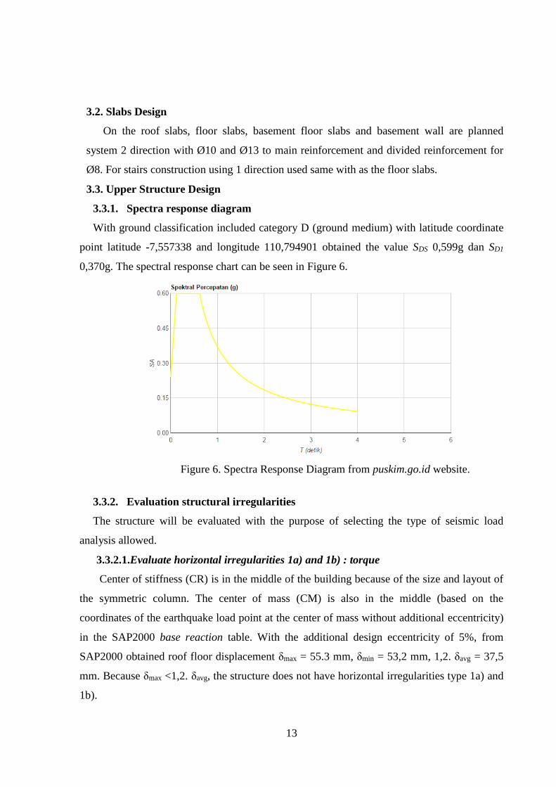
With ground classification included category D (ground medium) with latitude coordinate
point latitude -7,557338 and longitude 110,794901 obtained the value SDS 0,599g dan SD1
0,370g. The spectral response chart can be seen in Figure 6.
Figure 6. Spectra Response Diagram from puskim.go.id website.
3.3.2. Evaluation structural irregularities
The structure will be evaluated with the purpose of selecting the type of seismic load
analysis allowed.
3.3.2.1.Evaluate horizontal irregularities 1a) and 1b) : torque
Center of stiffness (CR) is in the middle of the building because of the size and layout of
the symmetric column. The center of mass (CM) is also in the middle (based on the
coordinates of the earthquake load point at the center of mass without additional eccentricity)
in the SAP2000 base reaction table. With the additional design eccentricity of 5%, from
SAP2000 obtained roof floor displacement δmax = 55.3 mm, δmin = 53,2 mm, 1,2. δavg = 37,5
mm. Because δmax <1,2. δavg, the structure does not have horizontal irregularities type 1a) and
1b).
14
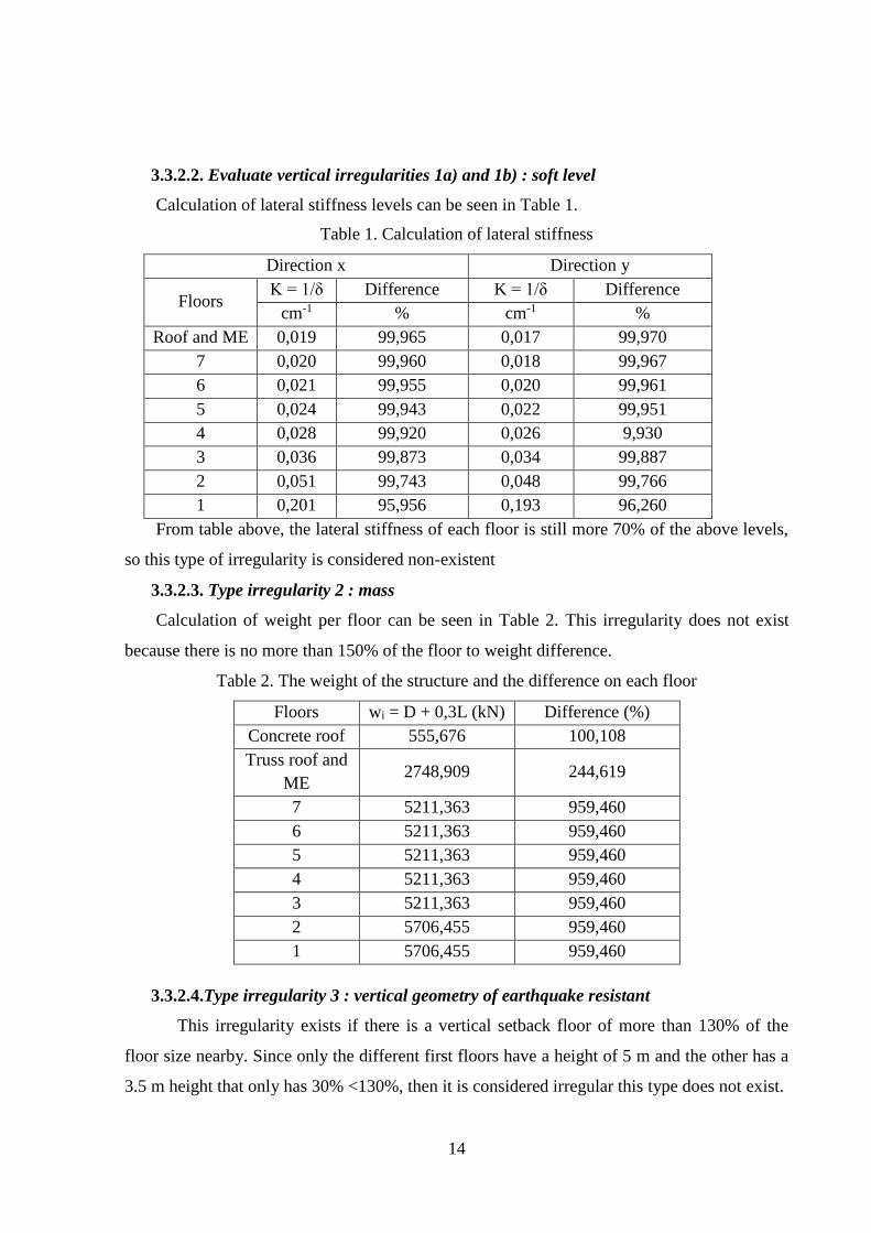
3.3.2.2. Evaluate vertical irregularities 1a) and 1b) : soft level
Calculation of lateral stiffness levels can be seen in Table 1.
Table 1. Calculation of lateral stiffness
Direction x Direction y
Floors K = 1/δ Difference K = 1/δ Difference
cm-1 % cm-1 %
Roof and ME 0,019 99,965 0,017 99,970
7 0,020 99,960 0,018 99,967
6 0,021 99,955 0,020 99,961
5 0,024 99,943 0,022 99,951
4 0,028 99,920 0,026 9,930
3 0,036 99,873 0,034 99,887
2 0,051 99,743 0,048 99,766
1 0,201 95,956 0,193 96,260
From table above, the lateral stiffness of each floor is still more 70% of the above levels,
so this type of irregularity is considered non-existent
3.3.2.3. Type irregularity 2 : mass
Calculation of weight per floor can be seen in Table 2. This irregularity does not exist
because there is no more than 150% of the floor to weight difference.
Table 2. The weight of the structure and the difference on each floor
Floors wi = D + 0,3L (kN) Difference (%)
Concrete roof 555,676 100,108
Truss roof and
ME 2748,909 244,619
7 5211,363 959,460
6 5211,363 959,460
5 5211,363 959,460
4 5211,363 959,460
3 5211,363 959,460
2 5706,455 959,460
1 5706,455 959,460
3.3.2.4.Type irregularity 3 : vertical geometry of earthquake resistant
This irregularity exists if there is a vertical setback floor of more than 130% of the
floor size nearby. Since only the different first floors have a height of 5 m and the other has a
3.5 m height that only has 30% <130%, then it is considered irregular this type does not exist.

15
3.3.3. Selection type analysis
Category of seismic design include D, equivalent lateral force then selected for the
following reasons :
a). Category of building risk is II.
b). The value of the vibration period of the structure is (Ta) < 3,5Ts (3,5.0,441 = 1,543 sec).
With formulas Ta = 0,0466.(33)0,9= 1,084 sec. Because Ta struktur < 3,5Ts, then this
requirement is met.
c). The building does not have horizontal irregularities type 1a), 1b) and vertical irregular
types 1a), 1b), 2 and type 3. Based on the evaluation in the previous section, the building
does not have irregularities of these types, then this requirement has been met.
3.3.4. Base reaction earthquake load
Effective seismic weight (Wt) is 42892,593 kN (D+0,3L). The value response
modification factor (R) is 5 and factor of building importance (Ie) 1,0. Value of the vibration
period approach (Ta) is 1,084 sec and Cu.Ta = 1,518 sec. The value of the exact vibration
period (Tc) results of computer count for direction x and y is 1,6066 detik 1,7001 sec, so that
vibrating period of use T = Cu.Ta.
Base reaction (Shear Force V) calculated :
Vx = Cx.Ie.Wt/R = 2092,389 kN
Vy= Cy.Ie.Wt/R = 2092,389 kN
3.3.5. Validation of mechanical analysis result
Validation of moments due to dead load Moment total = Distribution load (qD) +
Triangle load (qT) = 20,427 + 6,987 = 27,413 kNm (Restraint) At the value calculated by
SAP 2000 obtained the value of the moment on dead load 27,413 kNm because it has the
difference 0,00 % which approached then the results of the analysis SAP 2000 can be used for
calculation.

16
Figure 7. Load and moment due to dead load on SAP 2000.
Validation shear force base reaction equivalent lateral force
Table 3. Comparative analysis SAP 2000 and manual calculation
Type load
Check Difference
(%) SAP 2000 (kN) Manual calculation
(kN)
Dead 40326,357 40774,310 1,111
Live 7060,034 7060,944 0,013
Earthquake 2070,070 2092,389 1,078

17
Because the result of earthquake load calculation by using SAP 2000 and manual calculation
manual is approaching, then the earthquake load input done in SAP 2000 .15 is correct.
3.3.6. Story drift control
Story drift calculation is labeled in Table V.3. for the y direction, the largest drift also
occurs on the 2nd floor with a value of 5,355 cm. The drift value performed on the final
dimension of the building. The result of story drift is still below the permission drift story so
that the structure is safe against excessive deviation between floors.
Table 4. The calculation of the direction drift story control x
Floors (Δpermit)
(Cd) δe δ Drift (Δ)
cm cm cm cm
2 7 4,5 1,356 6,103 4,610
3.3.7. Beam and column design
Beam and column are designed with Moment Resisting Frame System with Medium
Ductility (IMRF) with plastic hinge at the ends of beams and columns. For longitudinal
reinforcement used diameter D22, torsion reinforcement D19 and reinforcement Ø10.
3.3.8. Beam and column design
The column should be reviewed if it is able to withstand 2 direction moment by
Bresler. The column under review is column K76 with a value = 0,2083 <1,00 so the column
is considered safe against the 2direction moment.
3.4. Under Structure Design
The under structure of pile, pile cap and sloof foundation.
a) The pile used with diameter of 400 mm, the length of the pile is 9 m. The foundation
depth of 18 m is divided into 2 segments, the longitudinal reinforcement used D13,
shear reinforcement 2ɸ10.
b) Foundation on P1 with pile cap size 2,4 x 2,5 x 0,75 m, P2 with pile cap size 3,2 x 3,2 x
0,75 m and P3 with pile cap size 3,2 x 2,1 x 0.75 m. The main reinforcement used D22,
the divide reinforcement is used D16.
c) Sloof used with dimension 350x700 with longitudinal reinforcement D22 and shear
reinforcement 2ɸ10.

18
4. CONCLUSIONS AND SUGGESTIONS
4.1. Conclusion
4.1.1. Roof truss design
a) The construction roof truss used 4 profile types,that is 2L.50.50.5 used for the frame
a1 - a10, b1 - b10 and v1 - v9. 2L.60.60.4 used for the frame v4 = v6. 2L.65.65.5
used for the frame v5 and 2L.50.50.6 used for the frame d1 - d 8.
b) The connection from profile structure used bolt connection with diameter 9,525 mm.
Number of bolts installed 3 bolts to frame name a and b. Number of bolts installed 2
bolts to frame name v and d. The knot plate have thickness 10 mm.
c) On the compression frame name a used kopel plate 50.50.5 with distance between
kopel plate is 462 mm. While on the compresin frame name v used 50.50.6 with
distance between kopel plate is 448 mm.
4.1.2. Slabs design
a) The slabs design with material reinforced concrete on the roof have thickness 100
mm and main reinforcement installed Ø10-175 and divided reinforcement installed
Ø8-200 on x and y direction.
b) The slabs design with material reinforced concrete on floors 1 to 7 and ME have
thickness 120 mm and main reinforcement installed Ø10-140 and divided
reinforcement installed Ø8-200 on x and y direction
c) The slabs design with material reinforced concrete on floors basement have thickness
250 mm and main reinforcement installed Ø12-130 and divided reinforcement
installed Ø10-155 on x and y direction. The quality used is BJTS 390 MPa
d) The wall basement design with material reinforced concrete have thickness 200 mm,
on the end installed main reinforcement Ø10-180 and divided reinforcement Ø10-
330. As for middle area installed main reinforcement Ø10-380 and divided
reinforcement Ø10-330. The quality used is BJTS 390 MPa
e) The stairs from first floors used reinforced concrete with thickness 120 mm with
optrade T = 18 cm and antrade I = 28 cm. On the bordes installed main
reinforcement Ø12-120 and divided reinforcement Ø8-200. As for stairs installed
main reinforcement Ø10-120 and divided reinforcement Ø8-200.

19
f) The stairs from basement, 2nd until mechanical electrical floors used reinforced
concrete with thickness 120 mm with optrade T = 18 cm and antrade I = 28 cm. On
the bordes installed main reinforcement Ø12-40 and divided reinforcement Ø8-200.
As for stairs installed main reinforcement Ø10-140 and divided reinforcement Ø8-
200.
4.1.3. Structure beam using IMRF
The structure main beam have dimension and diameter reinforcement as follows :
Table 5. Dimension beam and diameter installed
Floors Dimension beam Main
reinforcement
Shear
Reinforcement
1
500/700 Longitudinal
D22
shrinking
reinforcement
D19
4dp10
2
3
4
5
450/600 6
7
8
4.1.4. Structure beam using IMRF
Structure column have dimension 750/850 on the basement up to the top floor that is
mechanical electrical floors. Reinforcement used diameter D22 for longitudinal reinforcement
and 2dp10 for shear reinforcement.
4.1.5. Under structure design
The under structure consists of pile and sloof foundation. Pile used diameter 40 cm
with depth 18 m. type foundation name P1 used poer with size 2,4 x 2,5 x 0,75 m with have 5
piles, P2 used poer 3,2 x 3,2 x 0,75 m with 9 pile and as for foundation name P3 used poer 3,2
x 2,1 x 0,75 m with 5 pile. The sloof beam used dimension 350 x 700 mm with main
reinforcement Ø22 and shear reinforcement 2dp10.
4.1.6. Consideration of earthquake method
Earthquake load analysis is done with the help of SAP 2000 v.15. Building analysis using
two methods for consideration is Equivalent Lateral Force and Dynamic Spectrum Response
is as follows :

20
Table 6. Base reaction final on the method Equivalent Lateral Force and Dynamic Response
Spectrum
The building analyzed in this final project has 7 floors, basement and mechanical electrical
room with total height 33 m. Then the value of the method used can use the Equivalent
Lateral Force method in addition to the building has been analyzed by checking the structure
irregular still categorized regular buildings.
4.2. Suggestions
a) The structure of the building should be planned with good geometry to obtain a safe
and economical structure without losing the architectural aspect.
b) The structure of building will good design if have analysis together with shear, so that
the shear reinforcement not have space less than 100 mm. In addition, with the wall
shear of the building will be more rigid and can absorb nearly 90% of lateral forces
that work on the structure.
c) The standards regulation from SNI to load earthquake or reinforced concrete
designfor building should be well understood by the planner, so that planned
according to current conditions. Because basically the new regulations are published
based on the latest research from the related sciences.
d) Size dimensions of the structure (beams, columns and foundation) should be
determined by always attention to the ratio of concrete and iron reinforcement ratio so
that the cost of construction is more efficient.
e) The calculation use software as SAP2000 must needs to be done with the mastery of
the use of such software science and engineering conventional enough with the hope
of minimizing errors in its use.The process of modeling the structure, give load and
output of SAP 2000 should be done carefully and thoroughly and should be validated
as necessary by conventional methods to ensure that the output results are correct.
Output
Case Equivalent Lateral Force
Dynamic Response
Spectrum
Text Global FX
(kN)
Global FY
(kN)
Global FX
(kN)
Global FY
(kN)
QUAKE X -3611,02 0,00 3069,35 226,58
QUAKE Y 0,00 -3372,46 242,35 2866,57

21
REFERENCES
Asroni, A. 2010. Balok dan Pelat Beton Bertulang. Graha Ilmu. Yogyakarta.
Asroni, A. 2010. Kolom Fondasi & Balok T Beton Bertulang. Graha Ilmu.
Yogyakarta.
Asroni, A. 2009. Struktur Beton Lanjut. Program Studi Teknik Sipil Universitas
Muhammadiyah Surakarta. Surakarta.
BSN. 2013. Persyaratan Beton Struktural untuk Bangunan Gedung SNI 03-2847-
2013. Badan Standardisasi Nasional. Jakarta.
BSN. 2012. Tata Cara Perencanaan Ketahanan Gempa Untuk Struktur Bangunan
Gedung dan Non Gedung SNI 03-1726-2012. Badan Standardisasi Nasional.
Jakarta.
BSN. 2012. Beban Minimum untuk Perancangan Bangunan Gedung dan Struktur
Lain SNI 03-1727-2012. Badan Standardisasi Nasional. Jakarta.
BSN. 2002. Tata Cara Perencanaan Struktur Baja Untuk Bangunan Gedung SNI
03-1729-2002. Dinas Pekerjaan Umum.
BSN. 2002. Standar Perencanaan Ketahanan Gempa Untuk Struktur Bangunan Gedung
SNI-1726-2002. Departemen Permukiman Dan Prasarana Wilayah. Bandung.
Budiono, B. 2011. Studi Komparasi Desain Bangunan Tahan Gempa Dengan
Menggunakan SNI-03-1726-2002 dan RSNI 03-1726-201x. ITB. Bandung.
FEMA 451. 2006. NEHRP Recommended Provisions : Design Examples. Building Seismic
Safety Council National Institute of Building Sciences. Washington D.C.
Pawirodikromo, W. 2012. Seismologi Teknik dan Rekayasa Kegempaan. Pustaka
Pelajar. Yogyakarta.
Redana, I. W. 2010. Teknik Pondasi. Udayana University Press. Bandung.
Rochman, A. 2012. Pedoman Penyusunan Tugas Perancangan Atap. Program
Studi Teknik Sipil Universitas Muhammadiyah Surakarta. Surakarta.
Taranath, Bungale S. 2009. Reinforced Concrete Design of Tall Buildings. CRC Press.
Florida.

22
Hanafi, M.B. 2015. Perencanaan Struktur Apartemen 5 Lantai + 1 Basement Dengan
Sistem Rangka Pemikul Momen (SRPMM) Di Sukoharjo. Program Studi Teknik
Sipil Universitas Muhammadiyah Surakarta. Surakarta.