built environment heating systems non-domestic hot water · design, installation, ... cibse...
TRANSCRIPT
Engineering a sustainablebuilt environment
Non-domestic hot waterheating systems
The Chartered Institution of Building Services Engineers222 Balham High Road, London SW12 9BS+44 (0) 20 8675 5211www.cibse.org
Non-dom
estic hot water heating system
sA
M14
9 7 8 1 9 0 6 8 4 6 1 2 1
ISBN 978-1-906846-12-1
AM14: 2010
This publication is supplied by CIB
SE
for the sole use of the person making the dow
nload. The content remains the copyright property of C
IBS
E

Non-domestic hot water heating systems
CIBSE AM14: 2010
Engineering a sustainablebuilt environment
The Chartered Institution of Building Services Engineers
222 Balham High Road, London SW12 9BS
This publication is supplied by CIB
SE
for the sole use of the person making the dow
nload. The content remains the copyright property of C
IBS
E

The rights of publication or translation are reserved.
No part of this publication may be reproduced, stored in aretrieval system or transmitted in any form or by any meanswithout the prior permission of the Institution.
© January 2010 The Chartered Institution of Building ServicesEngineers London
Registered charity number 278104
ISBN 978-1-906846-12-1
This document is based on the best knowledge available atthe time of publication. However no responsibility of anykind for any injury, death, loss, damage or delay howevercaused resulting from the use of these recommendations canbe accepted by the Chartered Institution of Building ServicesEngineers, the authors or others involved in its publication.In adopting these recommendations for use each adopter bydoing so agrees to accept full responsibility for any personalinjury, death, loss, damage or delay arising out of or inconnection with their use by or on behalf of such adopterirrespective of the cause or reason therefore and agrees todefend, indemnify and hold harmless the CharteredInstitution of Building Services Engineers, the authors andothers involved in their publication from any and all liabilityarising out of or in connection with such use as aforesaidand irrespective of any negligence on the part of thoseindemnified.
Typeset by CIBSE Publications
Printed in Great Britain by The Charlesworth Group,Wakefield, West Yorkshire WF2 9LP
Cover: The Boilersuit, Guy’s Hospital, London (architect:Thomas Heatherwick Studio); photograph © EdmundSumner (VIEW Pictures Ltd.)
Note from the publisherThis publication is primarily intended to provide guidance to those responsible for thedesign, installation, commissioning, operation and maintenance of building services. It isnot intended to be exhaustive or definitive and it will be necessary for users of the guidancegiven to exercise their own professional judgement when deciding whether to abide by ordepart from it.
Any commercial products depicted or described within this publication are included forthe purposes of illustration only and their inclusion does not constitute endorsement orrecommendation by the Institution.
Printed on recycled paper comprising at least 80% post-consumer waste
This publication is supplied by CIB
SE
for the sole use of the person making the dow
nload. The content remains the copyright property of C
IBS
E

ForewordWhen first published in 1989, CIBSE Applications Manual AM3 provided guidance on anovel form of boiler for heating systems and domestic hot water — the condensing boiler.In the intervening period, the place of the condensing boiler in heating and hot watersystems has changed to the point where, in almost all cases, they are now required by theBuilding Regulations. Standards for such systems have evolved from the old BritishStandards into new European Standards, which focus far more on removing barriers totrade than overcoming barriers to understanding how to install and commission modernboilers, heating and control systems.
Other regulations have also emerged in that time, notably the Boiler Efficiency Directive,as well as the Energy Using Products Directive. The environmental agenda has alsotravelled far in that time, from Rio to Kyoto and then on, via Bali, to Copenhagen.
From a position of self sufficiency in oil and gas from the harsh operating conditions of theNorth Sea, and a quarter of UK electricity generated from nuclear plant, we now havedwindling nuclear supplies as our aging reactors reach the end of their working lives, andare increasingly dependent on gas from the harsher political climate east of the Urals.
There is no avoiding the need for the United Kingdom to reduce its energy use by alleconomically effective means. Doing so is essential to improve the security of our supplies,and to minimise the huge capital costs of the next generation of electricity plants, whateverfuel they use. Taking these actions now will also help us to reduce man-made emissions ofcarbon dioxide into the atmosphere.
The politics of CO2 emissions may be clouded, but the chemistry is very simple. The bondbetween carbon and oxygen absorbs radiation at a certain wavelength, so that carbondioxide traps radiation and prevents it leaving the atmosphere — the ‘greenhouse gas’effect. If there is more CO2 in our atmosphere, it will retain more heat. This fact wasestablished by the Swedish chemist Arrhenius in the late 19th century.
It is also increasingly clear that the existing building stock needs considerable investmentto reduce its energy consumption, and replacement of heating systems will play a significantrole in achieving this. There is a pressing need to provide advice on the refurbishment ofexisting buildings and retrofitting of heating systems within them.
It is therefore timely for CIBSE, working with ICOM Energy and experts from themanufacturing, design, and installation and commissioning sectors, to produce this newApplications Manual, giving comprehensive guidance on the design, installation, commis -sioning and operation and maintenance of heating systems. It also addresses the two verydifferent aspects of design: that intended for a new building, and that for a refurbishmentor retrofit project.
This publication should be widely read and used by all those responsible for heatingsystems in non-domestic buildings, and should contribute significantly to providing betterheating in many buildings.
This publication would not have been possible without the tireless efforts of the volunteerson the Steering Group, as well as the contracted authors from BSRIA, and the professionaleditorial and publishing team at CIBSE. The Institution and the wider readership areindebted to them.
Dr Hywel Davies
CIBSE Technical Director
Principal authorArnold Teekaram (BSRIA Ltd.)
This publication is supplied by CIB
SE
for the sole use of the person making the dow
nload. The content remains the copyright property of C
IBS
E

AM14 Steering CommitteeArnold Teekaram (BSRIA Ltd.) (Chair)Keith Brant (Exhausto Ltd.)David Davies (CIBSE)Hywel Davies (CIBSE)Yan Evans (Baxi Heating UK Ltd.)Peter Gammon (Modular Heating Group plc)Barry Gregory (Riello Ltd.)Malcom Gunn (Hamworthy Heating Ltd.)David Hughes (ICOM Energy Association)Fiona Lowrie (BSRIA Ltd.)Stephen Laws (Clyde Energy Solutions Ltd.)George Moss (Burgess Group)Keith Nelson (Broag Ltd.)Brian Price (Broag Ltd.)Peter Roge (Exhausto Ltd.)Wayne Rose (Armstrong Holden Brooke Pullen Ltd.)Claire Ruston (CIBSE) (Secretary)
AcknowledgementsCIBSE gratefully acknowledges the contribution of material for inclusion in thispublication by the following: Mike Campbell (AECOM), Robin Curtis and Don Sullivan(Earth Energy Ltd.), Guy Hundy (Institute of Refrigeration) and Rosemary Rawlings.
The Institution also gratefully acknowledges the following for permission to reproducegraphs, text and illustrations: AECOM, Aqua Environmental Ltd., Armstrong HoldenBrooke Pullen Ltd., Armstrong Integrated Systems Ltd., Baxi Commercial Division, BroagLtd., BSRIA Ltd., Clyde Energy Solutions Ltd., Dresser-Rand Ltd., Earth Energy Ltd.,Econergy Ltd., Exhausto Ltd., Fröling GmbH., Hamworthy Combustion EngineeringLtd., Hoval Ltd., Institution of Gas Engineers and Managers, Kensa Engineering Ltd., DrSteve Lo, MHS Boilers Ltd., Minikin and Sons Ltd., Riello Ltd., Spirotech Ltd., TrentConcrete Ltd., Viessmann Ltd.
The Institution is grateful to Mike Campbell (AECOM), Ian Richardson (NG Bailey Ltd.)and Andy Sneyd (Crown House Ltd.) for kindly reviewing the draft prior to publication.
EditorKen Butcher
CIBSE Technical DirectorHywel Davies
CIBSE Director of InformationJacqueline Balian
This publication is supplied by CIB
SE
for the sole use of the person making the dow
nload. The content remains the copyright property of C
IBS
E

Contents1 Introduction
1.1 Background1.2 How to use this Applications Manual1.3 Sources of further informationReferences
2 Design decisions and criteria: new buildings2.1 Introduction2.2 Strategic design decisions2.3 Design criteria for boilers in new buildingsReferences
3 Design decisions and criteria: refurbishment3.1 Introduction3.2 Drivers for refurbishment3.3 Scope for refurbishment3.4 Constraints3.5 Statutory regulations and guidance3.6 Identification of existing heating types3.7 Evaluation of existing heating systems3.8 Evaluation of heating loads3.9 Reducing energy consumption3.10 Options for refurbishment using low carbon technologies3.11 Whole life costs and payback3.12 Performance criteria for replacement boiler plantReferences
4 Major components of heating systems4.1 Introduction4.2 Heat sources (boilers)4.3 Distribution network4.4 Heat emitters4.5 Flue and chimney design4.6 Air supply and ventilation4.7 Fuel storageReferences
5 Controls5.1 Introduction5.2 Circuit design5.3 Boiler controls5.4 Avoiding excessive boiler cycling5.5 Demand-based boiler control and system inhibit5.6 Boiler sequence control5.7 Burner controls5.8 Time controls5.9 Temperature controls5.10 Hot water controlsReferences
6 Installation6.1 General6.2 Legislation and guidance6.3 Site facilities6.4 On-site storage and protection of equipment
1-11-11-11-31-4
2-12-12-1
2-122-22
3-13-13-13-23-43-53-63-7
3-103-103-113-173-183-21
4-14-14-1
4-244-354-394-454-494-52
5-15-15-15-35-35-35-35-45-45-55-75-7
6-16-16-16-16-2
This publication is supplied by CIB
SE
for the sole use of the person making the dow
nload. The content remains the copyright property of C
IBS
E

6.5 Installation of equipment6.6 Installation of circulation and distribution equipment6.7 Installation of heat emittersReferences
7 Testing, commissioning and maintenance7.1 Introduction7.2 System testing7.3 System cleaning, flushing and water treatment7.4 Pre-commissioning7.5 Commissioning7.6 Final reporting and documentation7.7 Continued evaluation and record keepingReferences
8 Troubleshooting for hot water heating systems8.1 IntroductionReference
Index
6-46-56-76-8
7-17-17-17-27-47-47-67-77-7
8-18-18-4
I-1
This publication is supplied by CIB
SE
for the sole use of the person making the dow
nload. The content remains the copyright property of C
IBS
E

1-1
1.1 Background
This new CIBSE Applications Manual has evolved as aresult of the following:
— the need to revise CIBSE AM3: Condensingboilers(1)
— the pending withdrawal of parts of BS 6880: Codeof practice for low temperature hot water heatingsystems of output greater than 45 kW(2)
— the implications of the changes to the BuildingRegulations(3) introduced in 2006
— the requirements of the Energy Performance inBuildings Directive(4) and its implementation inthe UK(5).
CIBSE Applications Manual AM3, first published in 1989,dealt specifically with the application of condensingboilers. At that time condensing boilers were the first highefficiency boilers, mainly for natural gas, and were used inthe UK in small numbers. Their use was not encouragedby legislation and, apart from a number of voluntary‘green’ schemes, there was little incentive to use them.
Since the publication of CIBSE AM3, there have beensignificant advances in technology and, with commit -ments to reduce carbon emissions, legislation is now inplace that prohibits the use of inefficient boilers for manydomestic and commercial space heating and hot waterproduction/applications.
BS 6880(2) was for many years a comprehensive guide forengineers involved in the design, installation and commis -sioning of non-domestic heating systems. Its nominalreplacement, BS EN 12828(6) (published in 2003), onlycovers system design and in far less detail than the earlierstandard. Matters covered in BS 6880: Part 2: Selection ofequipment and Part 3: Installation, commissioning andmaintenance are not addressed in BS EN 12828.
The changes to the Building Regulations(3) in 2006imposed more stringent requirements for energyefficiency and carbon emission reduction, which apply toboth new and existing buildings. This imposes additionalrequirements for designers and installers who areupgrading existing systems. What was once a simple boilerreplacement now needs more thought and detailedknowledge of the building, the system and its controls toenable the engineer not only to comply with theRegulations, but also to implement an efficient andeffective system. In addition, to ensure that boilers complywith the Regulations, extra measures may need to betaken, such as improvement in operating temperaturecontrols and zoning.
Existing heating systems are highly diverse in design andthis can mean that some are relatively simple to upgradewhilst others present much more of a challenge.Knowledge of the types and designs of existing systems,their initial design criteria and their limits will help theengineer to make the correct decisions.
1.1.1 Purpose
This Applications Manual provides guidance on thedesign, installation and commissioning of water basedheating systems. It addresses both the design of heatingsystems for new buildings and the specific requirementsrelating to the design of replacement systems, orrefurbishment of existing systems, in the existing buildingstock. It does not cover medium temperature or hightemperature hot water systems (i.e. those having flowtemperatures above 90 °C).
1.1.2 Readership
The guidance is intended for designers and those whoinstall and commission heating systems and theircomponents. It is important that those who designsystems, particularly for existing buildings, have regardfor the installation and commissioning require ments. Notonly do they and their employers have a statutory duty toconsider the safe construction and installation of theirdesign, but it also yields benefits in terms of betterperformance, improved maintainability and lower costsover the life cycle of the system. The guidance thereforeconsiders installation and commis sioning alongsidedesign requirements.
1.2 How to use thisApplications Manual
This publication is intended to describe a logical sequenceof processes for engineers to enable them to designefficient heating systems. It covers water based heatingsystems for buildings other than dwellings with a totalinstalled capacity from 45 kW up to 2 MW. Domestic hotwater generation is outside the scope of this publication.
The design decisions and criteria for space heating andhot water systems for new buildings and existing buildingrefurbishment projects are covered in chapters 2 and 3respectively of this Manual.
For new buildings, a number of key strategic designdecisions are outlined. These include planning andsustainability issues. ‘Sustainable development’ is now
1 Introduction
This publication is supplied by CIB
SE
for the sole use of the person making the dow
nload. The content remains the copyright property of C
IBS
E
1-2 Non-domestic hot water heating systems
becoming a major criterion underpinning planning.Specific targets for low carbon buildings and the use ofrenewable energy are being set by many local authorities.Examples of sustainability issues relating to the design ofthe building, reduction in energy and CO2 emissions andNOx pollution are given in section 2 of the guide.Examples of other key strategic design decisions that needto be considered in the early design stages of the projectinclude the intended occupancy of the building and itsuse, thermal comfort, interaction with the building design,building fabric, services and facilities, the client’s budget,fuel supply and heat generators.
Guidance in these areas is given with additional referencesfor further reading. The operating strategy of the heatingplant is covered with specific reference to the use ofcontrols. Various strands of legislation that affect thedesign of the heating system are covered, such as Part L ofthe Building Regulations(3). The standards and guidancedocuments that support the requirements, such as the NonDomestic Heating, Cooling and Ventilation ComplianceGuide(7), CIBSE Guides and British and EuropeanStandards, are identified.
The criteria for the design of heating systems for newbuildings are given in section 2.3. Heating systems areclassified according to the temperature regime over whichthey operate and the corresponding operating pressure.The guidance is aimed mainly at low temperature hotwater (LTHW) systems with condensing boilers. The choiceof the internal and external design temperatures,calculation of the fabric and ventilation heat loss and useof reheat factors are included. A simple methodology forcalculation of the total design building heat load using thesteady state approach is given.
The minimum seasonal efficiency criteria and controlrequirements that must be met by boilers in new buildingsin order to comply with Building Regulations ApprovedDocument L2A(8) are also reviewed.
An existing system presents more challenges thandesigning a new system. Not only does the engineer need afull understanding of the type of system installed, but alsoan understanding of the logic and intent behind its designat the time of installation. Only with this knowledge canreasonable decisions be made on upgrading. Chapter 3 hastherefore been written specifically for refurbishmentprojects. The main drivers for refurbish ment areidentified, including failed heating plant, improvingperformance of existing heating plant etc. For thepurposes of this document, the scope of refurbishment isdefined at three levels: minor refurbish ment, majorrefurbishment and complete refurbishment. A flowchartfor a major refurbishment is included. The refurbishmentof existing heating systems is often subject to constraintsand these are identified.
There are various types of heating systems currentlyinstalled in buildings. These are described so that existingsystems undergoing refurbishment can be easily iden -tified. Guidance is also given that will assist the evaluationof current systems so that logical decisions can be maderegarding the appropriate level of refurbishment.Evaluation of the existing heating load is reviewed andthree methods are given to enable this to be determined.Options for refurbishment using low carbon technologyare given, including the use of solar thermal technology,
combined heat and power (CHP) and the application ofbiomass boilers. Life cycle analysis costs and payback arereviewed with respect to the replacement of plant. Theminimum efficiency and controls requirements forreplacement boiler plant are also included.
Guidance on the use of renewable and low carbontechnologies is given in chapters 3 and 4. This is achanging field and there is currently little authoritativeguidance available. This document therefore refers to thevarious technologies and directs readers to more detailedguidance where this is available.
Chapter 4 describes the major components of the heatingsystem, including a review of the technologies used bydifferent boilers. Recent advances in the field ofrenewables, such as biofuel boilers and heat pumps, arecovered. The majority of hot water heating systemscurrently installed in buildings are of the constant volumetype with fixed speed pumps for the primary andsecondary circuits. Developments in variable speedpumping technology have since led to variable flowheating systems as an alternative to the constant volumeheating system and are reviewed here.
The main components within the distribution hot watersystem such as pumps, flow measurement and regulatingdevices are also covered and guidance is given oncomponent selection. The different types of heat emittersare reviewed and reference made to underfloor heating.Detailed guidance is given on flue and chimney designwith respect to natural and mechanical draught systemswith particular emphasis on condensation occurringwithin the flue or chimney. Requirements for combustionair supply and ventilation are given, based upon theguidance already given in published British Standards.Fuel storage, particularly that required for biomass andliquid biofuels, and requirements for reheating and waterremoval are covered. The requirements for water treat -ment, safety controls and electrical installation are alsocovered in detail.
Chapter 5 reviews the basic types of controls for heatingsystems. This chapter is not intended to deal with thesubject in great detail and reference is therefore made toCIBSE Guide H(9), CIBSE KS4(10) and CIBSE Guide F(11),which offer extensive information. The minimum controlrequirements required to meet the Building Regulations(3)
are also included.
Chapter 6 seeks to offer guidance on the installation ofLTHW systems and ancillary equipment. These include theinstallation considerations for principal items of equip -ment, including heat sources, water circulation anddistribution systems, heat emitters, controls and otherassociated plant items.
Chapter 7 provides an overview of the installation, testing,commissioning and maintenance of heating systems ingeneral. This subject covers everything from static testingof newly installed pipework, through the flushing andcleaning and finally the testing and commissioning of thesystems. It should be noted that many documents existcovering each aspect of this subject in detail. This chaptertherefore provides an overview of the process.
A ‘troubleshooting’ guide is given in chapter 8. Thisidentifies typical problems, causes of failure and solutions
This publication is supplied by CIB
SE
for the sole use of the person making the dow
nload. The content remains the copyright property of C
IBS
E

Introduction 1-3
relating to hot water heating systems. It covers typicalproblems relating to the heat generator, flue, systemhydraulics, controls and commissioning
1.3 Sources of furtherinformation
1.3.1 Building Regulations
The Building Regulations(3) set requirements forminimum levels of energy efficiency. They are supportedby Approved Documents and other publications:
— Building Regulations Approved Document L2A:Conservation of fuel and power for new buildings otherthan dwellings
— Building Regulations Approved Document L2B:Conservation of fuel and power for existing buildingsother than dwellings
— Non Domestic Heating, Cooling and VentilationCompliance Guide
— Low or Zero Carbon Energy Sources: Strategy Guide
The above documents may be downloaded free of chargefrom the government’s ‘Planning Portal’ website (http://www.planningportal.gov.uk). It should be noted that a newedition of Part L of the Building Regulations is likely tobe published in 2010.
The procedure for demonstrating compliance with theBuilding Regulations for buildings other than dwellings isby calculating the annual energy use for a proposedbuilding and comparing it with the energy use of acomparable ‘notional’ building. The calculation may becarried out either using approved simulation software, orby a simplified tool developed by BRE called the‘Simplified Building Energy Model’ (SBEM) with itsassociated basic user interface (iSBEM). The followingdocuments provide guidance:
— User guide to iSBEM (Simplified Building EnergyMethod)
— A Technical Manual for SBEM.
These documents may be downloaded free of charge fromthe ‘National Calculation Method’ website (http://www.ncm.bre.co.uk).
1.3.2 CIBSE guidance
The following CIBSE documents give further detailedguidance on the design decisions, system design, controls,commissioning and maintenance for energy efficientsystems and building. Details of these and other CIBSEpublications may be found on the CIBSE website (http://www.cibse.org/publications).
CIBSE Guides are regarded as the most authoritativepublications produced by the Institution and numerousreferences to these Guides will be found in otherdocuments mentioned below:
— CIBSE Guide A: Environmental design: chapter 3:Thermal properties of building structures.
— CIBSE Guide B: Heating, ventilating, air conditioningand refrigeration: chapter 1: Heating
— CIBSE Guide C: Reference data: chapter 4: Flow offluids in pipes and ducts
— CIBSE Guide F: Energy efficiency in buildings
— CIBSE Guide H: Building control systems
— CIBSE Commissioning Code B: Boilers
— CIBSE Commissioning Code C: Automatic controls
— CIBSE Commissioning Code M: Commissioningmanagement
— CIBSE Commissioning Code W: Water distributionsystems
— CIBSE TM27: Flexible building services for office-based environments: principles for designers
— CIBSE. TM29: HVAC strategies for well-insulatedairtight buildings
— CIBSE TM31: Building log book toolkit
— CIBSE TM38: Renewable energy sources for buildings
— CIBSE TM39: Building energy metering.
The CIBSE Knowledge Series gives straightforward,practical advice for engineers and the following titles areparticularly relevant to this Applications Manual:
— CIBSE KS2: Managing your building services
— CIBSE KS4: Understanding controls
— CIBSE KS5: Making buildings work
— CIBSE KS6: Comfort
— CIBSE KS7: Variable flow pipework systems
— CIBSE KS8: How to design a heating system
— CIBSE KS9: Commissioning variable flow pipeworksystems
— CIBSE KS10: Biomass heating.
CIBSE Briefings give an overview of topical subjects andmay be downloaded free of charge from the CIBSEwebsite. Although some date back to 2002, they offeruseful background information to more current guidance.Those relevant to this document are listed below:
— CIBSE Briefing 6: The Energy Performance inBuildings Directive
— CIBSE Briefing 7: Energy efficiency in refurbishment
— CIBSE Briefing 8: Reducing emissions through energyefficiency
— CIBSE Briefing 10: Thermal comfort in a 21st centuryclimate.
The above CIBSE Briefings may be downloaded free ofcharge from the CIBSE website (https://www.cibse.org/membersservices/downloads). It is necessary first to log-in,either as a member or non-member.
This publication is supplied by CIB
SE
for the sole use of the person making the dow
nload. The content remains the copyright property of C
IBS
E

1-4 Non-domestic hot water heating systems
1.3.3 HVCA guidance
The Heating and Ventilating Contractors’ Association(HVCA) offers guidance for heating and ventilationcontractors on various topics associated with health andsafety, site management and installation.
Generally, published guidance on pipework installationand testing is very limited. The following are the mostrelevant parts of HVCA TR20: Installation and Testing ofPipework Systems:
— HVCA TR20: Part 1: Low temperature hot waterheating
— HVCA TR20: Part 9: Natural gas
— HVCA TR20: Part 10: Fuel oil.
Details of these and other HVCA publications may befound on the HVCA website (https://shop.welplan.co.uk).
1.3.4 Further guidance
Although published some years ago, the following BritishStandards offer sound and practical advice:
— BS 6644: 2005 + A1: 2008: Specification forinstallation of gas-fired hot water boilers of rated inputsof between 70 kW (net) and 1.8 MW (net) (2nd and3rd family gases)
— BS 6880: Code of practice for low temperature hotwater heating systems of output greater than 45 kW(3 parts)
— BS 5410: Code of practice for oil firing. Installationsup to 45 kW output capacity for space heating and hotwater supply purposes (2 parts).
Details of British Standards may be found on the BSIwebsite (http://www.bsigroup.com).
References1 Condensing boilers CIBSE AM3 (London: Chartered Institution
of Building Services Engineers) (1989) (out of print)
2 BS 6880: Code of practice for low temperature hot water heatingsystems of output greater than 45 kW: Part 1: 1988: Fundamentaland design considerations; Part 2: 1988: Selection of equipment;Part 3: 1988: Installation, commissioning and maintenance(London: British Standards Institution) (1988)
3 The Building Regulations 2000 Statutory Instruments 2000 No2531 as amended by The Building (Amendment) Regulations2001 Statutory Instruments 2001 No. 3335 and The Buildingand Approved Inspectors (Amendment) Regulations 2006Statutory Instruments 2006 No. 652 (London: The StationeryOffice) (dates as indicated) (available at http://www.opsi.gov.uk/stat.htm) (accessed August 2009)
4 Directive 2002/91/EC of the European Parliament and of theCouncil of 16 December 2002 on the energy performance ofbuildings (‘The Energy Performance of Buildings Directive’)Official J. of the European Communities L1/65 (4.1.2003)(Brussels: Commission for the European Communities) (2003)(available at http://ec.europa.eu/energy/demand/legislation/buildings_en.htm) (accessed August 2009)
5 The Energy Performance of Buildings (Certificates andInspections) (England and Wales) Regulations 2007 StatutoryInstruments 2007 No. 991 (London: The Stationery Office)(2007) (available at http://www.opsi.gov.uk/stat.htm) (accessedAugust 2009)
6 BS 12828: 2003: Heating systems in buildings. Design for water-based heating systems (London: British Standards Institution)(2003)
7 Non Domestic Heating, Cooling and Ventilation Compliance Guide(London: NBS/Department of Communities and LocalGovernment) (2006) (available at http://www.planningportal.gov.uk/uploads/br/BR_PDF_PTL_NONDOMHEAT.pdf)(accessed August 2009)
8 Conservation of fuel and power in new buildings other than dwellingsBuilding Regulations 2000 Approved Document L2A (London:The Stationery Office) (2006) (available at http://www.planningportal.gov.uk/england/professionals/en/1115314231806.html)(accessed August 2009)
9 Building control systems CIBSE Guide H (London: CharteredInstitution of Building Services Engineers) (2009)
10 Understanding controls CIBSE KS4 (London: CharteredInstitution of Building Services Engineers) (2005)
11 Energy efficiency in buildings CIBSE Guide F (London:Chartered Institution of Building Services Engineers) (2004)
This publication is supplied by CIB
SE
for the sole use of the person making the dow
nload. The content remains the copyright property of C
IBS
E

2-1
2.1 IntroductionThis chapter covers the design decisions and criteria thatshould be considered when designing a heating system fora new building. More detailed guidance for existingbuildings is contained in the chapter 3.
In the design of heating systems for new buildings, anumber of key strategic design decisions must be made atthe outset of the project. These include sustainability andplanning issues at local level and the use of low and zerocarbon technology* to reduce the energy consumption andCO2 emissions. The client may also specify targets forBREEAM(1) (or equivalent) and asset rating for energyperformance certification. The design of the heatingsystem has a significant influence on whether or not suchtargets will be met. Some guidance on sustainability isgiven here but further information can be found in theIntroduction to sustainability(2) and CIBSE Guide L(3).Guidance on some of the key strategic design decisionsrequired is given in section 2.2. Section 2.3 gives designcriteria for new buildings and calculation of the totalbuilding heating load. The minimum requirements forefficiency and controls are also given.
2.2 Strategic design decisionsFigure 2.1 shows a strategic design decision flow chart forheating systems in new buildings. It shows some of thekey issues that should be considered during the designprocess. These are covered in the following sections. (Seealso CIBSE Knowledge Series KS8(4) for further guidanceon the design process for heating systems.)
2.2.1 Planning and sustainabilityissues
The successful criteria for the heating system design are:
— the installation and commissioning of a systemthat can deliver the required indoor temperatureswithin client budget
— a system that operates with high efficiency (i.e.minimise fuel costs and environmental emissions)
— a system that can sustain the performance over theplanned lifetime with limited need for unplannedmaintenance and replacement of components
— a system that complies with legal requirements(e.g. Building Regulations Part L(5), planningpolicies, commissioning, environmental impact,health and safety requirements) and meets anyadditional voluntary targets.
Section 4 of CIBSE Guide L(3) gives guidance on how thebuilding services engineer can contribute to assist projectsthrough the planning process. ‘Sustainable development’is now becoming the main criterion underpinning plan -ning. Many local authorities have specific targets for lowcarbon buildings and for a percentage contribution fromrenewable energy.
Guidance on how spatial planning should contribute toreducing emissions and stabilising climate change is givenin the Department for Communities and LocalGovernment (CLG) Planning Policy Statement 1:Planning and climate change(6). It increases pressure on newdevelop ments to:
— meet low and zero carbon targets (includingBuilding Regulations Part L emissions targets)
— take account of the effects of climate change
— provide a coherent response to issues related toclimate change such as flood risk, biodiversity andsustainable transport.
Table 2.1, reproduced from CIBSE Guide L, shows the keydocuments required for a major planning application.
At the early stages of the design process, it is important toaddress sustainability issues and to understand the impactthat engineering decisions can have on a sustainable builtenvironment. Sustainable issues can influence the designbrief, the choice of heating plant and the energy and CO2emissions for the building. CIBSE Guide L gives theguidance on a range of sustainable issues and outlines thegeneral principles to be applied. In the design of a heatingsystem for new buildings, the principles of sustainabilityshown in Table 2.2 apply. The building services engineerwill have direct control over the sustainability issues givenin the table. He/she will be able to make a usefulcontribution that can influence the design strategy andshould be involved at the early stages while there is stillmaximum scope to integrate appro priate solutions tominimise the costs. As a key member of the project team,building services engineers are also in a position to raiseother sustainability issues and contribute to addressingthem.
It is essential that a strategic brief is drawn up by theclient that will provide consultants with the necessaryrequirements on which to tender. Sustainability objec -tives, targets, and criteria for measuring performance anddetermining success should be an integral part of thebriefing process. If the strategic brief does not address
2 Design decisions and criteria: new buildings
* Definitions of low and zero carbon technology as used for the ‘MertonRule’ (see section 2.2.1) are as follows: ‘A zero carbon development is onethat achieves zero net carbon emissions from energy use on site, on anannual basis. A low carbon development is one that achieves a reductionin carbon emissions of 50% or more from energy use on site, on anannual basis.’ (http://www.themertonrule.org)
This publication is supplied by CIB
SE
for the sole use of the person making the dow
nload. The content remains the copyright property of C
IBS
E

2-2 Non-domestic hot water heating systems
Consider sustainability issues,reduction in energy demands from renewables, use of low and zero carbon technologies. Review planning requirements with local authority
Strategic design decisions flowchart for heating systems in
new buildings
Obtain design brief. Identify client requirements. Obtain information about the building and its use
Establish key design data and parameters that relate to the design of the heating system (e.g. system operating temperatures, boiler flow rates)
Determine heating and cooling loads based on occupancy and processes, pattern of use
Propose choice of plant and fuel type
Can the system work within the design parameters?
Submit for approval to client
Produce tender M&E specification document, schedules and specifications
Check design meets clientrequirements for performance,quality, reliability, energy targets and complies with Regulations
Produce design of heating system and control strategy. Check suitability of system with design team
Information about the buildingwould include, for example, its fabric, thermal mass, building airtightness, orientation, shadingand location, glazing locationsetc. Obtain plan, elevation andstructural drawings, access toboiler plant rooms
For example, condensing boilers, high efficiency modular boilers.Consider potential of low and zero carbon (LZC) technologies, e.g CHP, bio-mass boilers, solar thermal systems and ground source heat pumps. Consider space limitations, fuel type and sustainability implications, fuel storage. Check proposed location of flue terminal, solar panels, fuelstorage etc. with planners. Checkstructural loadings withstructural engineer if relevant
For example, constant volume system/variable volume heating system. Produce layout drawings of primary and secondary flowheating circuits. Consider thehydraulics of the flow circuits,choice of heat emitters andpositions, ventilation requirements for boiler house, flue arrangement (e.g. natural draught/mechanical draught/fan diluted system)
Consider occupancy of building, pattern of usage; what passive heating and cooling features are intended for the building? (e.g. solar shading, natural or mechanical ventilation, advanced fenestration, energy targets)
Determine: fabric losses plus ventilation losses plus heating-up capacity
Consider statutory and regulatory requirements, e.g: Clean Air Act; DCLG requirements; Building Regulations Parts A (Structure), B (Safety in fire), F (Ventilation), G3 (Hot water storage), J (heat producing appliances), L2A and L2B (Conservation of fuel and power); Gas Safety (installation and use) Regulations; Health and Safety at Work Act; CDM Regula-tions; COSHH Regulations; Water Supply Regulations
No
Yes
Figure 2.1 Design process for heating systems (see also CIBSE KS8(4), Figures 4 and 5, for further guidance on the design process)
This publication is supplied by CIB
SE
for the sole use of the person making the dow
nload. The content remains the copyright property of C
IBS
E

Design decisions and criteria: new buildings 2-3
Table 2.1 Planning submission documents(3)
Key document Likely author Comments
Environmental statement (ES) Environmental consultants See CIBSE Guide L, section 4.2.3, on environmental impact assessments and with a number of experts environmental statements. Information may be required from engineers on air quality from CHP etc.
Sustainability statement (SS) Sustainability consultant Often presented as a separate document, but can be included as an additional chapter in ES. Will draw on information from the energy strategy report.
Energy strategy report Building services engineer An energy strategy report should be prepared for major projects (see CIBSE Guide L (currently mainly for section 4.2.1).projects in London)
Design and access statements Architect Should include sustainability issues relating to the architecture and accessibility of the scheme.
Planning statements Planning consultant Draws together and summarises the findings of all studies undertaken in support of planning to make the case for the granting of planning application for the site and seeks to demonstrate compliance with planning policy.
Table 2.2 Principles of sustainability for heating system in new buildings
Sustainability issue Principles to be applied
Design of building Consider site layout, building form, orientation and building fabric. Building envelope should be designed toeliminate thermal bridging (heat loss through conduction directly to the environment) and promote thecontinuity of insulation, to minimise building fabric heat losses.
In England and Wales, insulation standards must achieve the minimum area-weighted U-values as given inBuilding Regulations Approved Document L2A(5) for new buildings. Carry out thermal modelling to assesswhether there is any advantage on improving the thermal insulation values. Building Regulations Part L2Ashould be considered as a minimum standard and not as an aspirational target.
Make effective use of thermal mass to minimise heating up capacity of boiler plant.
Design to minimise ventilation and air infiltration losses. All new buildings are required to be pressure testedin accordance with Building Regulations Approved Document L to a test pressure of 50 Pa. The design airpermeability limit at this pressure is 10 m3·h–1/m2. For buildings that have been heated to provide thermalcomfort, air leakage can result in significant energy losses. Buildings should be designed to achieve airpermeability rates that are significantly lower than the minimum standards specified in Approved DocumentL. Further information can be obtained from CIBSE TM23: Testing buildings for air leakage(7).
Energy and CO2 emissions Reduce demand: this can be achieved by improving the design of the building as described above and byminimising the heat losses from the boilers, pipework and storage. Locate plant to minimise the distributionsystem. In the design of a new building, this should be discussed with the architect at the very early stages ofthe project. Heat losses are minimised by insulating distribution pipework, valves and flanges in the plantroom.
Meet end-use demand by specifying the most efficient boiler(s), e.g condensing boilers. Size plant withappropriate margins but avoid oversizing (see CIBSE KS8(4)). Check the installed capacity and energyperformance against benchmarks and rules of thumb in cases where thermal modelling of the building has notbeen carried out. (See CIBSE Guide F(8) section 10.4, and Carbon Trust publication ECG019: Energy use inoffices(9)). Select fuels and tariffs that promote energy efficiency and minimise running costs. Also consider de-centralised heating plant on large sites to reduce standing losses and improve load matching (see CIBSEGuide F(8) Tables 10.5 and 10.6 for advantages and disadvantages of centralised and local plants).
Consider energy supply from low carbon or zero carbon technologies (e.g. CHP, heat pumps, ground sourceheat pumps, solar thermal) and the feasibility of renewable energy (e.g. biomass and liquid biofuel hot waterheating boilers). It is essential to consider low/zero carbon technologies and renewable options early in thedesign process and how to integrate these with fossil fuel heating boilers. Refer to the GLA Guide 10:Integrating renewable energy into new developments: Toolkit for planners, developers and consultants(10) for furtherinformation.
Enable energy management, e.g. by including effective controls on primary plant and distribution systems.Incorporate controls based on temperature, time, zones, variable flow, based on the requirements of thebuilding. Provide effective occupant controls, e.g. TRVs in all rooms. Specify an effective building energymanagement system. Consider controls at an early stage in the design. See CIBSE Guide F(8) section 10.3.Specify effective energy metering strategy in accordance with Building Regulations(5) requirements.
Pollution Reduce pollution at source, e.g. specify boilers with low NOx emissions.
Undertake disposal of pollutants in an environmentally safe manner, e.g. disposal of ash from wood pelletboilers. Biomass boilers below 400 kW thermal output are not subject to regulatory control unless they arelocated within a smoke control area. The Clean air Act 1993(11) requires that, except in exempt appliances,only authorised fuels may be used in designated smoke control areas. Authorised fuels include gas, anthraciteand specified manufactured smokeless fuels, but not biomass. In order to qualify as an exempt appliance, abiomass boiler must be subject to specific testing.
Take adequate precautions to prevent pollution at source, e.g. storage of fuel oil in propriety pre-fabricated oiltanks must be bunded. See CIRIA publication C535: Above-ground proprietary prefabricated oil storage tanksystems(12), Pollution Prevention Guidelines PPG2(13) and PPG27(14) and BS 5410: Part 2(15).
This publication is supplied by CIB
SE
for the sole use of the person making the dow
nload. The content remains the copyright property of C
IBS
E

2-4 Non-domestic hot water heating systems
sustainability, then the building services engineers shouldconsider the drivers for addressing sustainability issuesearly in the project.
Examples of key drivers are:
— European legislation (e.g. Ecodesign for Energy-Using Products Directive (EUPD)(16)*, EnergyPerformance in Buildings Directive (EPBD)(19),Energy Services Directive (ESD)(20))
— Regulations (e.g. Building Regulations ApprovedDocuments L1A(21) and L2A(22))
— planning policies
— client requirements.
Addressing issues early in the project may highlightunexpected requirements from, for example, regional andlocal planning policies, Building Regulations and theclient’s own corporate policy on social responsibilities. Anexample of local planning policy that has a direct impact isthe ‘Merton Rule’, which is applicable to the LondonBorough of Merton and, at the time of publication, isbeing adopted as a planning require ment in other areas.This sets a target for the use of on-site renewable energy toreduce annual CO2 emissions for all new major develop -ments in the Borough of Merton by 10%. Integratingsustainable solutions in the strategic brief from the outsetshould not be overlooked as this could be very cost-effective in terms of time, effort and finance.
Sustainability objectives should be supported byperformance standards.
2.2.2 Occupancy and building use
The level of occupancy and building use are key factorsthat should be considered in strategic design stages.Consideration should be given to the following factors:
— periods of occupation
— whether the occupants are sedentary or physicallyactive
— what heat gains will arise due to occupancy andactivities, including heat gains from associatedequipment (computers, office machinery etc.);where specified, these can be taken into account inthe energy efficiency calculations but, for Part Lcompliance, the building shell, which is the mostenergy-intensive scenario, should be used
— whether or not all areas of the building havesimilar requirements
— future re-allocation of floor space: considerationshould be given to whether or not the system canbe adapted to meet potential changes in occupancypatterns.
2.2.3 Thermal comfort
Usually heating is required to maintain comfortableconditions for the occupants, either for working or living
conditions. Thermal comfort depends on environmentalfactors:
— temperature of the air
— temperature of the surrounding exposed surfaces
— air movement
— humidity
— air quality.
The Workplace (Health, Safety, Welfare) Regulations(23)
stipulate that the temperature of the working environmentshall be ‘reasonable’. Operative temperature (formerlyknown as ‘dry resultant temperature’) combines the airand mean radiant temperatures and is generally the mostimportant environmental factor in the assessment ofthermal comfort. (See section 2.3.3 for further discussionof operative temperature.) Guidance on temperaturessuitable for a range of indoor spaces is given in CIBSEGuide A(24), Tables 1.5 and 1.7, and BS EN ISO 7730(25).
Moving air will have a cooling effect, which can give riseto unwanted draughts for some occupants. Guidance onthe effect of air speed on operative temperature, compen -sation for occupant activity and calculation of draughtrating for air conditioned and mechanically ventilatedbuildings can be found in CIBSE Guide A, section 1.3.The relative air speed over an occupant increases asactivity increases and the operative temperature may needfurther correction to compensate for the additionalcooling effect. It must also be noted that fluctuations in airspeed contribute to discomfort; turbulence intensity is ameasure of this effect. A draught rating can be calculated,as described in CIBSE Guide A, section 1.3.
Humidity has little effect on warmth for most practicalsituations and a range of 40–70 %RH is consideredacceptable.
Thermal comfort also depends on personal factors:
— metabolic heat production
— clothing.
Metabolic heat production is highly dependent onactivity; where the activities vary throughout the day aweighted-average metabolic rate can be used to estimateheat generation. Typical values of heat generation forvarious activities can be found in CIBSE Guide A, Table1.4.
The clothing worn by occupants of a building will dependon the season and outdoor weather conditions as well asthe indoor temperature. Examples of the insulationprovided by clothing and the corresponding change inoperative temperature are listed in CIBSE Guide A, Table1.3. BS EN ISO 7730(25) gives more detailed informationabout thermal comfort.
Where possible, the heating system design should addressall of the above to ensure that unacceptable conditions donot occur.
The subject of thermal comfort is covered in detail in thefollowing publications:
— CIBSE Guide A: Environmental design(24)
* The EUP Directive has incorporated the minimum boiler efficiencyrequirements specified in the Boiler Efficiency Directive(17) and has beenimplemented in the UK by the EUP Regulations 2007(18).
This publication is supplied by CIB
SE
for the sole use of the person making the dow
nload. The content remains the copyright property of C
IBS
E

Design decisions and criteria: new buildings 2-5
— CIBSE Guide B: Heating, ventilating, air conditioningand refrigeration(26)
— CIBSE KS6: Comfort(27)
— CIBSE Briefing 10: Thermal comfort in a 21st centuryenvironment(28)
— BS EN ISO 7730: 2005: Ergonomics of the thermalenvironment(25).
Unoccupied areas may require heating to control thetemperature or humidity for the following reasons:
— to protect building fabric or contents, e.g. fromfrost, condensation etc.
— to provide the environmental conditions requiredby processes carried out in the space
— for certain applications (e.g. preservation ofartifacts, reduction of static electricity), a highhumidity may be preferred.
In all cases the time taken to reach comfort conditionsfrom start-up must be considered.
2.2.4 Interaction between buildingdesign, building fabric, servicesand facilities
Important characteristics that influence the heatingsystem include:
— building form and orientation
— building layout: windows, internal thermal mass,levels of fabric insulation
— building airtightness and ventilation
— location of plant rooms and space for and routingof distribution networks
— requirement to heat hot water in addition toheating.
Once again the importance of involving the buildingservices engineer at the strategic design decisions stagemust be stressed, since input in the above areas cancontribute to optimising the building performance.
The building layout is linked to building form andorientation, e.g. the decisions made on the use of daylightwill influence window design and the amount and type ofglazing used. The amount of solar gain the buildingexperiences will in turn influence the capacity and spacerequired for the heating system. The internal thermalmass of the building is a measure of its capacity to storeheat; the higher the value, the slower the rate oftemperature change of the building. The effect on heatinga building from cold, e.g. at the start of the day, must beconsidered since a high thermal mass will require a largerheating system or a longer pre-heat time.
The building’s airtightness and ventilation affect theamount of heat loss. Unintentional heat loss occursthrough defects in the building fabric (walls, roof, floor)and is influenced by several factors, including the amountof insulation. An estimate of the building’s airtightnesscan be made using a fan pressurisation test. Intentionalventilation is determined by the intended use of the
building and both natural and mechanical means can beused to ensure adequate air changes.
Plant rooms can be located anywhere inside or outside thebuildings and it is important that access is readilyavailable for maintenance and other purposes. The spacemay be limited due to requirements of other users so it isimportant to determine potential constraints as early aspossible, including access and egress for plant and equip -ment and for personnel in an emergency. The size andamount of the pipework used in certain systems must beincorporated early into the building design and ampleservice ducts provided for its transition through thebuilding. The route and calculations for the discharge ofcombustible products via flues should be agreed andconfirmed early in the design process, as should thelocation and space required for emitters on walls etc. Theheat loss from the distribution network must also beaccounted for in the overall heat loss calculations.
In applications where the hot water loads are not high it isgenerally more energy efficient to provide a separate directfired hot water system rather than to combine hot waterand heating systems. Combination boilers can be used forsmall sized centralised systems but the heating and hotwater systems may interact during winter demands. Theinstallation of ‘point of use’ electric water heaters could beconsidered for low load or infrequent hot water use. Incases where the hot water load is high, this may be thefactor that drives boiler requirements.
2.2.5 Operating strategy
The client must advise of their approach to overallbuilding design and operation. Factors to considerinclude:
— energy strategy including use of renewable energysources, energy efficiency
— maintenance
— control of system, i.e. manual/automatic controls,level of complexity for users etc.
The use of low and zero carbon energy sources for newbuildings is being encouraged by regulations and canmake a significant contribution to reducing the overallenergy costs of the building. It is generally more straight -forward to incorporate these technologies at the designstage, as part of an intrinsically energy-efficient design,than to retrofit them. Over-specification of services andexcessive design margins should be avoided.
Maintenance tasks can be considered as unplanned(breakdown) and planned (preventative) tasks. Unplannedtasks include not only faults which cause loss of servicebut also those which result in energy wastage; these latterfaults should be considered a priority if energy efficiencyis to be maintained. Careful monitoring of energy use canhighlight such faults. Planned main tenance should reducethe risk of breakdown or loss of performance. It can becarried out either at specified times or when specifiedconditions occur. CIBSE Guide F(8), chapter 17, containsfurther information regarding maintenance checks forenergy related systems.
Controls provide the main interface between the buildingoccupants and the building services and so it is essential to
This publication is supplied by CIB
SE
for the sole use of the person making the dow
nload. The content remains the copyright property of C
IBS
E
2-6 Non-domestic hot water heating systems
include user controls within the strategy. Good control ofthe heating system makes a vital contribution to lowenergy consumption. Ideally heat will be provided onlywhen and where it is needed, at the required temperatureand with minimal boiler cycling. Often this requires thebuilding to be divided into zones, where a zone is a set ofrooms or areas that require the same heating conditionsand so can be placed on the same control circuit. BuildingRegulations Approved Document L2A(5) stipulates thatcontrol zones should be used where possible.
Zone control can be implemented using thermostaticradiator controls on individual emitters, or by usingmotorised valves, room thermostats and time controls thatare independent of the main heating time control.Programmable room thermostats are a convenient way ofachieving these secondary systems. Multiple secondarycircuits should be connected in parallel across a commonheader so that each circuit has access to the full heatsource(8). It should be noted that the ability to adjust theindoor environment locally contributes to occupantsatisfaction, see CIBSE Guide B(26), section 1.3.2.
2.2.6 Budget
The client’s budget must be adhered to. The budgetshould take into account:
— design costs
— capital costs of heating plant
— installation and commissioning
— day-to-day running, including fuel costs
— maintenance and repairs
— the climate change levy on energy bills
— enhanced capital allowances for energy and watersaving technologies.
2.2.7 Site related issues
Particular characteristics of a site must be accounted for,including:
— exposure: geographical location and height abovesea level, local microclimate, local conditions
— site access for plant items
— connection to facilities (affects choice of fuel)
— form and orientation of building: this can have asignificant effect on heating/cooling demands, e.g.exposure to solar gain, shading by surroundingbuildings etc.
Exposure to climatic conditions can make a significantdifference to the energy requirements of a building. Thegeneral considerations when designing the building are toreduce unwanted heat gains in summer and heat lossesduring winter.
Site access includes the access required to work on the siteduring building construction and access for manoeuvringand installing the heating plant items in their specificlocations. Access should also be provided for systemmaintenance and plant replacement. Access in all casesmust allow work to be carried out safely; further
information can be found in the Construction (Design andManagement) Regulations(29) (CDM Regulations), item 26.
The effect of the building’s form on its energy use dependson several factors, including shape, mass (usually floors,external walls and roofs are the most critical elements),insulation, glazing and lighting. Good roof insulation ismore important with low-rise buildings than high-rise.Frequently a compromise must be reached between theneed for natural lighting and ventilation and the desire tominimise heat loss through glazing. The orientation of thebuilding with respect to surrounding buildings mayinfluence daylight penetration, and hence solar gains, andmay also create undesirable wind patterns around thebuilding. Passive solar gains may be maximised byorientating the building so that windows face south. Thesetopics are considered in CIBSE Guide F: Energy efficiencyin buildings(8).
2.2.8 Fuel supply and heat generators
A decision has to be made early in the design process onwhich type of fuel is to be used. The choice of fuel willmainly determine the building emissions rate target.Other factors that would determine the choice of fuel arethe efficiency criteria of the boiler plant, availability,storage facilities and price.
Where natural gas is available, this tends to be the obviouschoice of fuel as there is no requirement for storage, itoffers clean combustion and there is a wide choice ofsuitable appliances. Liquid petroleum gas (LPG), althoughhaving the advan tages of gas appliances, does requirestorage facilities. With oil, only distillate fuels class C2(kerosene) and class D (gas oil) tend to be used for 2 MWappliances and under. Kerosene can be used in smallerappliances but reference must also be made to the burnermanufacturer.
The choice of renewables can be limited when the fuel islinked with hot water heating systems as heat pumps andsolar panels are not always able to supply the higher watertemperatures required without gas-fired ‘top-up’. Liquidor solid biomass can be used as alternatives to conven -tional liquid and solid fuels. Solid biomass (mainly woodor waste pellets) burning appliances on a commercialscale, although they do have some degree of automation,require manual supervision and facilities have to be madefor ash removal.
Liquid biofuels have been developed as a sustainablesubstitute for liquid fossil fuels. The pure blends areregarded as ‘carbon neutral’ because the CO2 emittedwhen they are burnt is equal to that which was absorbedfrom the environment over the lifetime of the fuel source(i.e. the crop). See section 4.2.10 for more details.
Thermal solar heating may be suitable for hot waterservice generation but is not often appropriate for heatingsystems because heating is most likely to be needed whenthe availability of solar energy is at its least. Hot waterdemand is more intermittent than space heating therebyallowing the thermal solar energy an opportunity torecharge the thermal store.
This publication is supplied by CIB
SE
for the sole use of the person making the dow
nload. The content remains the copyright property of C
IBS
E

Design decisions and criteria: new buildings 2-7
2.2.8.1 Gas fired heat generators
There has been a trend over the last few years to movefrom large single appliances to three, four, or more smallerunits to meet the total load. This change came about toimprove load matching and thus seasonal efficiency.
Developments in domestic, wall-hung condensing boilershas led to fully modulating commercial sized (>70 kW)wall-hung boilers. Many of these units can be cascadedand some have their own in-built sequence controls.
A major concern over the years with multiple boilers hasbeen considerable oversizing (up to 500% compared witheven the building maximum design load). This oversizingcreates a situation where one boiler is usually sufficient tomeet the total building load and the others are super -fluous. The heating load on most buildings is less than15% for most of the heating season.
2.2.8.2 Oil fired heat generators
Oil appliances covering this output range up to 2 MWtend to be of the pressure jet type. Burners can be single,multiple stages or modulating.
Where oil appliances are utilised, operating temperaturesare more critical than for gas in order to avoid acidcondensation in the boiler flueways and flue system. It isnormal to operate oil-fired boilers at a constant tempera -ture unless the appliance is capable of operating at lowwater temperatures. Oil-fired condensing boilers areavailable but the condensate has to be neutralised. Theamount of latent heat available in the flue gases is not asgreat as that for gas-fired appliances.
2.2.9 Controls
CIBSE KS4: Understanding controls(30) gives an accuratesummary of many building heating control systemsinstalled and operating today:
Controls and control systems are an essential part of buildings,from the simple switching on and off of equipment tosophisticated building management systems that monitor andoptimise plant performance to meet building needs. Nowadaysit is impossible to avoid the use of control systems, whichnecessitates some knowledge of what they do, and how theyfunction, in order to be able to ask for the right level of controlin the first place and to operate the controls successfully.
It is essential to establish how to control the system as partof the initial design concept and not as an afterthought.Important questions that need to be answered are:
— What will the building be used for?
— Who occupies it, where and when?
— What is the building orientation and what are thethermal effects of this?
— Are there any areas of high heat gain from othersources?
— Are there any areas with special requirements?
With this knowledge areas can be zoned and grouped inorder of time, temperature and load control. More detaileddescriptions and use of the types of controls available are
given in chapter 4 on plant types and system design. Inaddition, there are several documents giving usefulguidance on controls:
— CIBSE Guide H: Building control systems(31)
— CIBSE Guide F: Energy efficiency in buildings(8)
— CIBSE KS7: Variable flow pipework systems(32).
Minimum requirements for controls to comply with theBuilding Regulations are summarised in section 2.3.10;controls required for the complete heating system detailedin chapter 5.
2.2.10 Energy efficiency targets
The requirement for energy efficient buildings is drivenby the need both to reduce fuel costs and to minimiseenvironmental damage through CO2 emissions. To meetthe latter requirement, in 2003 the UK Governmentpublished an Energy White Paper: Our energy future —creating a low carbon economy(33), which set out the aim forthe UK to reduce carbon emissions by 60% of currentlevels by 2050. Other challenging targets are to be met enroute, such as reducing carbon dioxide emissions by 20 %of the 1990 level by 2010. The strategy includes bothfinancial incentives and regulations.
Taxes have been introduced to reduce energy consumption(e.g. the climate change levy on industrial and commercialenergy supplies) and allowances provided to encourage thetake-up of energy efficient technologies.
In 2003 the Energy Performance of Buildings Directive(19)
(EPBD) was implemented, which led to revisions toBuildings Regulations Part L2(5). These changes have setnew standards for energy efficiency in new buildings andrequire energy consumption, as measured by annual CO2emissions per unit useful floor area, to be reduced by15–20% of 2002 levels. There is some variation in therequired reduction depending on the style of building, e.g.air conditioned or mechanically ventilated buildingscompared to naturally ventilated buildings. Examples ofthe range of energy consumption and CO2 emissions fordifferent types of office building are given in EnergyConsumption Guide ECG019: Energy use in offices(9). Inaddition, designers are encouraged to considerincorporating low and zero carbon technologies, whichcan make substantial and cost-effective contri butions toreducing CO2 emissions.
The EPBD requires Member States to adopt a commonmethodology to calculate the energy performance ofbuildings in order to demonstrate compliance. The UKhas developed a National Calculation Methodology fornew non-dwellings, which is implemented through theSimplified Building Energy Model (SBEM) or otherapproved software to calculate the carbon emissions. Thisallows a target CO2 emission rate (TER) to be calculated, asdescribed below, and then compared to the actual buildingCO2 emission rate (BER); to comply with the BuildingRegulations the BER must not be worse than the TER. Inorder to comply with the Regulations minimum construc -tion criteria must also be met. Note: the BER is not thevalue of CO2 emitted from the boiler, but is a rating of theentire building.
This publication is supplied by CIB
SE
for the sole use of the person making the dow
nload. The content remains the copyright property of C
IBS
E

2-8 Non-domestic hot water heating systems
Several dynamic simulation packages that are commonlyused for design are approved for the purposes ofcalculating the emissions ratings, and therefore designersusing these tools can calculate emissions ratings anddemonstrate compliance within the package. This requiresdata on boiler performance, and so the characteristics ofthe boiler and heating system have an impact on thecompliance calculations for the design.
2.2.10.1 Calculation of TER
The TER is the mass of CO2 emitted per year per m2 of thetotal useful floor area of the building. It is determinedfrom the following formula:
TER = (Cnotional)
× (1 – improvement factor)
× (1 – LZC benchmark) (2.1)
where Cnotional is the CO2 emission level for a buildingconstructed notionally in the year 2002 which has thesame size, shape and use as the building under consider -ation but has a set of specified properties (this is calculatedusing the approved software tool), the improve ment factoris the improvement in energy efficiency appropriate to theclasses of building services in the proposed building, theLZC benchmark is the bench mark provision for LZCtechnologies (Note: the LZC technologies are notmandatory in order to comply with Building Regulationsbut may be mandatory to comply with local authorityplanning requirements.)
2.2.10.2 Calculation of BER
The BER is the mass of CO2 emitted by the actual buildingunder consideration and the value should be equal orlower than the TER. It must be calculated using the samesoftware tool as for the TER and should be based on thebuilding as finally constructed. Therefore it must includeany changes to the performance specifications madeduring construction and include the measured airpermeability, ductwork leakage and fan performances ascommissioned. The CO2 emission factors for various fuelsgiven in Table 2.3 should be used in the BER calculation.Following the final calculations, notice should be submit -ted to the local authority specifying the TER and BER. Note:the BER is not a value of CO2 emitted from the boiler, butthe rating of the entire building.
The following applies in situations where a system couldbe fired by more than one fuel type:
— For biomass-fired systems with an output rating>100 kW, but where there is an alternativeappliance (e.g. fossil fuel) as a backup system, theCO2 emission factor should be based on the fueltype that is expected to provide the lead.
— For systems with an output rating <100 kW,which are capable of burning both biofuel andfossil fuel, the CO2 emission factor for dual fuelappliances should be used unless the building is ina smoke control area; in this case the factor foranthracite should be used.
— For all other cases the fuel with the highest CO2emission factor should be used.
From October 2008, an Energy Performance Certificate,stating a building’s energy rating and how it could beimproved, must be produced following construction of anynon-dwelling building. A building logbook, containingdetails of the energy performance of the building, mustalso be maintained.
Effective metering of energy consumption throughout abuilding is essential if these targets are to be demonstratedand new buildings should include meters that allow 90%of energy consumption to be measured.
Further information can be found in the followingreferences:
— Good Practice Guide 306: Energy managementpriorities — a self-assessment tool(35) gives informa -tion on calculating energy outgoings.
— CIBSE Guide F: Energy efficiency in buildings(8)
gives detailed guidance on energy efficiency.
— CIBSE TM39: Building energy metering(36) considerslegislation and best practice regarding energymetering.
— CIBSE TM22: Energy assessment and reportingmethod(37) describes method of calculating energyperformance of buildings.
— Energy and carbon emissions regulations(33) sets outthe legislative, regulatory and planning mech -anisms in force within the UK
Table 2.3 CO2 emission factors (source: Building Regulations ApprovedDocument L2A(5); Crown copyright)
Fuel CO2 emission factor* / (kgCO2/kW·h)
Natural gas 0.194 (0.206)
Liquid petroleum gas 0.234 (0.251)
Biogas 0.025 (0.024)
Oil 0.265 (0.284)
Coal 0.291 (0.382)
Anthracite 0.317 (0.365)
Smokeless fuel (inc. coke) 0.392 (0.402)
Dual fuel appliances (mineral plus wood) 0.187 (0.243)
Biomass 0.025
Electricity:— grid supplied 0.422 (0.591)— grid displaced[1] 0.568 (0.591)
Waste heat[2] 0.018
* Values in parenthesis are those likely to be published in the 2010edition of Building Regulations Approved Document L2A(34); readersshould check these values with the published edition when available
Notes:
[1] Grid displaced electricity comprises all electricity generated in or onthe building premises by, e.g., PV panels, wind-powered generators,combined heat and power (CHP), etc. The associated CO2 emissionsare deducted from the total CO2 emissions for the building beforedetermining the BER. CO2 emissions arising from fuels used by thebuilding’s power generation system (e.g. to power the CHP engine)must be included in the building CO2 emissions calculations.
[2] This includes waste heat from industrial processes and powerstations rated at more than 10 MWe and with a power efficiency>35%.
This publication is supplied by CIB
SE
for the sole use of the person making the dow
nload. The content remains the copyright property of C
IBS
E

Design decisions and criteria: new buildings 2-9
2.2.11 Legal, economic and generalconsiderations (UK)
Various strands of legislation affect the design of heatingsystems in the UK, as described below. These regulationsare supported by various guidance documents. Note thatlegislation is subject to amendment and the text belowrefers to the versions current at the time of writing.Readers should assure themselves that they are using themost up-to-date versions of regulations etc.
Regulations are contained in primary and secondarylegislation (Acts and Regulations, respectively) and mustbe complied with. The following relate to some aspects ofheating systems:
— The Building Regulations(39)
— Workplace (Health, Safety and Welfare)Regulations 1992(23)
— Gas Safety (Installation and Use) Regulations1998(40) and their equivalent for NorthernIreland(41)
— Gas Appliances (Safety) Regulations 1995(42)
— Dangerous Substances and Explosive AtmospheresRegulations 2002(43)
— Construction (Design and Management)Regulations 2007(44) (‘CDM Regulations’)
— Electricity at Work Regulations 1989(45)
— The Fire Precautions Act 1971(46) (implementedthrough several sets of regulations, see below)
— The Clean Air Act 1993(11)
— Chimney Heights: 1956 Clean Air Act Memorandum(3rd edition)(47)
— Environment Act 1995(48).
These are described in detail below.
2.2.11.1 Building Regulations
England and Wales
The Building Regulations are made under powersprovided in the Building Act 1984(49) as amended by theSustainable and Secure Buildings Act 2004(50), and applyin England and Wales. They provide minimum standardsacross a range of design issues, particularly health andsafety, but also energy conservation and access. Thecurrent Building Regulations date from 2000, as theBuilding (Approved Inspectors etc.) Regulations 2000(51).The most recent changes to Part L were introducedthrough the Building and Approved Inspectors(Amendment) Regulations 2006(52).
In addition to the Building Regulations and the scheduleof requirements (known as Parts A to P) that they contain,there are a number of Approved Documents, which are‘approved and issued by the Secretary of State for thepurpose of providing practical guidance with respect tothe technical requirements of the Building Regulations2000 for England and Wales.’
Furthermore, as stated in the introduction to theApproved Documents, they are:
intended to provide guidance for some of the more commonbuilding situations. However, there may well be alternativeways of achieving compliance with the requirements [of theBuilding Regulations]. Thus there is no obligation to adopt anyparticular solution contained in an Approved Document if youprefer to meet the relevant requirement in some other way.
Building Regulations Approved Document L2A:Conservation of fuel and power in new buildings other thandwellings(5) provides practical guidance with respect to therequirements on conservation of fuel and power in newnon-domestic buildings. It covers the limiting of heatgains and losses, the provision of energy efficient buildingservices and controls and how to provide sufficientinformation to the building owner to enable the buildingto operate using no more fuel and power than isconsidered reasonable.
For heating systems, the Department for Communitiesand Local Government has produced a compliance guidespecifically for non-domestic systems: Non-DomesticHeating, Cooling and Ventilation Compliance Guide(53). This‘second-tier’ document contains guidance on theminimum provision to enable compliance with ApprovedDocument L2A(5). Pertinent to heating systems, the guidecovers plant efficiency, controls, suggestions for improvingefficiency and insulation of pipes, ducts etc. In particularit describes seasonal boiler efficiency, effective heatgenerating seasonal efficiency and heating efficiencycredits.
Scotland
In Scotland, the governing legislation is the Building(Scotland) Act 2003(54) and the current Regulations are theBuilding (Scotland) Regulations 2004(55). These aresupported by Technical Handbooks in lieu of ApprovedDocuments. There are two Handbooks, one for domesticbuildings(56) and one for non-domestic buildings(57).Section 6 of these Handbooks addresses the energyefficiency requirements.
Northern Ireland
In Northern Ireland the current primary legislation underwhich Building Regulations are introduced is the BuildingRegulations (Northern Ireland) Order 1979(58) (asamended 1990). The current Building Regulations are theBuilding Regulations (Northern Ireland) 2000(59).
2.2.11.2 Other legislation
Workplace (Health, Safety and Welfare) Regulations
The Workplace (Health, Safety and Welfare) Regulations1992: approved code of practice and guidance(60) (Health andSafety: Legal Series L24) is no longer current but is citedin the Building Regulations. This code contains furtherinformation and guidance concerning the Regulations.Topics relevant to heating systems include the main -tenance of equipment and systems, ensuring a reasonabletemperature of the internal environment, provision anduse of thermometers, and the prevention of dangerousfumes from the operation of heating or cooling systems.
This publication is supplied by CIB
SE
for the sole use of the person making the dow
nload. The content remains the copyright property of C
IBS
E

2-10 Non-domestic hot water heating systems
Gas Safety (Installation and Use) Regulations 1998
These Regulations(40) cover the safety, installation and useof gas fittings, including all aspects of gas transmission,distribution, supply or use. The fuels concerned arenatural gas and liquified petroleum gas. The regulationsalso cover the qualifications and duties of people involvedwith gas installation and use.
Gas Appliances (Safety) Regulations 1995
These Regulations(42) apply to all gas (including LPG)appliances used for, among other things, heating wherethe water temperature does not exceed 105 °C. They alsoapply to the fittings, controls and sub-assemblies.
Dangerous Substances and Explosive AtmospheresRegulations 2002
These Regulations(43) impose a duty on employers and theself-employed to protect people from risks to their safetyfrom fires etc. in the workplace.
Construction (Design and Management) Regulations2007
The key aims of the ‘CDM Regulations’(44) are to integratehealth and safety into the management of the project andto encourage everyone involved to work together toimprove the planning and management of projects;identify risks early on; target effort where it can do themost good in terms of health and safety; and discourageunnecessary bureaucracy.
The Electricity at Work Regulations 1989
The Electricity at Work Regulations 1989(45) apply to allworkplaces and the electrical equipment used in them.They require precautions to be taken against the risk ofdeath or personal injury from electricity in work activities,including routine visual inspections of equipment.
The Fire Precautions Act 1971
This legislation(46) deals with general fire precautionsincluding the means of detection and giving warning incase of fire; the provision of means of escape; the means offighting fire; and the training of staff in fire safety. Thereis also a requirement to undertake an assessment of thefire risks, covering both the risk of fire occurring and therisk to people in the event of fire. The fire authorities willissue a certificate only when satisfied that the buildingmeets the necessary standards.
The Act has been implemented by several sets ofregulations, such as Fire Precautions (Factories, Offices,Shops and Railway Premises) Order(61), the FirePrecautions (Hotels and Boarding Houses) Order 1972(62)
and those contained in Building Regulations Part B(63).These Regulations must not be contravened
Clean Air Act 1993
This Act(11) controls the emissions of dark smoke, grit,dust and fumes from industrial premises and furnaces and
allows Local Authorities to declare certain regions as‘smoke control areas’, in which smoke emissions areprohibited. It is also an offence to acquire an‘unauthorised fuel’ for use within a smoke control areaunless it is used in an ‘exempt’ appliance. Authorised fuelsinclude inherently smokeless fuels such as gas, electricityand anthracite together with specified brands ofmanufactured solid smokeless fuels. Exempt appliances,e.g. ovens, wood burners and stoves, have passed tests toconfirm that they are capable of burning unauthorised orinherently smoky solid fuels without emitting smoke. Thepellets or chips used in wood burners must not containhalogenated organic compounds or heavy metals. Theremay also be concern regarding particulates from biomass(wood) fuel in urban areas.
Chimney Heights: Third Edition of the 1956 Clean AirAct Memorandum
This publication(47) provides advice on the calculation ofappropriate chimney heights for new chimneys. It isapplies only to chimneys for fuel burning plant with grossheat input in the range of 0.15–150 MW.
2.2.11.3 Guidance and other documents
Guidance on how to implement regulations is usuallygiven by the relevant industry association or organisation,or by other bodies that are recognised as having authorityin the particular area. For heating systems these bodiesinclude:
— Oil Firing Technical Association (OFTEC): producesguidance for oil-fired appliances, including boilers.Standards can be found on the OFTEC website(http://www.oftec.org/oftec_standards.asp).
— Gas Safe Register: on 1 April 2009, the CORGIregistration scheme for gas installers was replacedby the Gas Safe Register, which is operated byCapita Gas Registration and Ancillary ServicesLtd. on behalf of the Health and Safety Executive.Guidance is available at the Gas Safe Registerwebsite (http://www.gassaferegister.co.uk).
— Heating and Ventilation Contractor’s Association(HVCA): represents the interests of firms active inthe design, installation, commissioning andmaintenance of heating products and equipment.Legal advice and health and safety guidance can befound on the HVCA website (http://www.hvca.org.uk).
— Institution of Gas Engineers and Managers (IGEM):guidance and technical standards may be obtainedfrom the IGEM website (http://www.igem.org.uk).
Standards that are of relevance to heating instal lations innew buildings include the following:
— BS EN 303-5: 1999: Heating boilers. Heating boilerswith forced draught burners. Heating boilers for solidfuels, hand and automatically fired, nominal heatoutput of up to 300 kW. Terminology, requirements,testing and marking(64).
— BS 6644: Specification for installation of gas-fired hotwater boilers of rated inputs between 70 kW (net) and1.8 MW (net) (2nd and 3rd family gases)(65). This
This publication is supplied by CIB
SE
for the sole use of the person making the dow
nload. The content remains the copyright property of C
IBS
E

Design decisions and criteria: new buildings 2-11
standard covers all main areas of installation of gasfired hot water boilers.
— BS 6880: Low temperature hot water heating systems ofoutput greater than 45 kW(66). Part 1 coversfundamental and design considerations, Part 2 theselection of equipment and Part 3 covers instal -lation, commissioning and maintenance.
— BS 7671: Requirements for electrical installations. IEEWiring Regulations. Seventeenth edition(67). TheseRegulations are the national standard to which alldomestic and industrial wiring must conform.
— BS EN ISO 7730: Ergonomics of the thermal environ -ment. Analytical determination and interpre tation ofthermal comfort using calculation of the PMV and PPDindices and local thermal comfort criteria(25).
— BS EN 12828: Heating systems in buildings. Designfor water based heating systems(68).
— IGE/UP/10 (edition 3): Installation of flued gasappliances in industrial and commercial premises(69).This publication covers the installation of a rangeof flued gas appliances, including hot water boilersof net heat input >70 kW. The guidance coverslocation, pipework, ventilation, chimneys, gasdetection and maintenance.
— IGEM/UP/2 (edition 2): Installation pipework onindustrial and commercial premises(70).
2.2.11.4 Environmental assessmentmethodologies
The environmental assessment of buildings is becomingincreasingly widespread. It entails a systematic assessmentof the proposed building, with a series of credits beingawarded for environmentally beneficial aspects of design.Building services, including heating systems, fall withinthe scope of such assessments.
In the UK, the predominant scheme is the BREEnvironmental Assessment Method (BREAM). Detailsmay be found at the BREEAM website (http://www.breeam.org). Other schemes that may be encounteredinclude the US Green Building Council’s Leadership inEnergy and Environmental Design (LEED) scheme(http://www.usgbc.org/LEED) and the Royal Institution ofChartered Surveyors’ SKA Rating (http://www.rics.org/ska).
2.2.12 Regulations, standards andguidance (Australia)
The following is a summary of Australian standards,regulations and guidance documents relating to condens -ing boilers and heating systems.
2.2.12.1 Building Code of Australia
The Building Code of Australia (BCA) is administered andmaintained by the Australian Building Codes Board(ABCB) (http://www.abcb.gov.au/go/home) on behalf of theAustralian Government and State Territory Governments.
BCA volume 1 addresses non-residential building types,which are arranged into nine sub-classes. Volume 2addresses all residential buildings and housing.
Section 5.4 of BCA volume 1 sets out the thermalefficiency of boilers that must be attained for compliancewith the Code.
Minimum Energy Performance Standards (MEPS)
These mandatory standards are set by state governments,and specify the minimum energy perform ance for plantand equipment that is sold in and imported into Australia.Details may be found on the MEPS website (http://www.energyrating.gov.au/meps1.html).
2.2.12.2 Australian Standards
The following Australian Standards apply to heatingsystem installations:
— AS 5601: 2004: Gas installations(71): this standardprovide specific details on pipe design and sizing,appliance installation and commissioning, fluedesign, and general work and safety requirementsfor gas installations.
— AS 2593: 2004: Boilers — Safety management andsupervision systems(72): this standard specifies therequirements for the operation of boilers,including special features within unattended (orlimited attendance) facilities, and details thechecking, testing and maintenance requirements.
— AS/NZS 1200: 2000: Pressure equipment(73): thisstandard covers the design, materials, manufac -ture, installation, commissioning, operation andinspection of pressure equipment (includingboilers, pressure vessels and pressure piping).
— AS 3788: 2006: Pressure equipment — In-serviceinspection(74): this standard covers the inspection,repair and in-service alteration of boilerequipment (i.e. boilers, pressure vessels andpressure piping).
2.2.12.3 Other guidance (Australia)
Green Building Council of Australia
The Green Building Council of Australia (GBCA) isresponsible for developing the ‘Greenstar’ environmentalrating system for buildings. It is intended for use byproject teams, contractors and other interested parties tovalidate the environmental initiatives at the design phase,the construction phase and the ‘as built’ phase. Part of thisassessment process is the rating of the building’s plant(including boilers) using the ‘Green Star’ energy calculatoror the Australian Building Greenhouse Rating (ABGR)rating tool.
The rating system awards from 4 to 6 stars, depending onthe overall environmental performance of the building orspace. Details may be found on the GBCA website(http://www.gbca.org.au).
This publication is supplied by CIB
SE
for the sole use of the person making the dow
nload. The content remains the copyright property of C
IBS
E

2-12 Non-domestic hot water heating systems
National Australian Built Environment Rating System
The National Australian Built Environment RatingSystem (NABERS) is an industry standard for measuringand benchmarking the environmental performance ofexisting buildings in Australia. The scheme is adminis -tered by the New South Wales state government.
The scheme awards from 1 to 5 stars depending on the‘greenhouse’ performance of the building or space. Boilerefficiency is included in the assessment. Details may befound on the NABERS website (http:www.nabers.com.au).
2.2.13 Making the strategic decisions
In conclusion, each case must be considered on its ownmerits and a rigorous appraisal of options based onfunctional, economic and environmental considerationsundertaken.
As mentioned earlier, it is likely that several iterations ofdesign will be required and the input from other teammembers involved in designing the building is essentialfor successful completion of the building.
2.3 Design criteria for boilersin new buildings
2.3.1 General
This section reviews the basic types of heating systemsand some of the important factors to be considered duringthe preliminary design stages. It also gives the designcriteria for the design of heating systems for new buildingsin relation to determining the building’s heating load. Acalculation method is included for determining theheating load in a building under standard design con -ditions to maintain the internal design temperature. Theheat load methodology given here assumes steady stateconditions assuming constant properties. This calculationwill enable the boilers to be sized accordingly. Themethodology presented here excludes the requirement fordomestic hot water. The heat load calculation requiresknowledge of the following parameters:
— internal design temperature
— external design temperature
— structure or fabric heat loss
— ventilation heat loss
— thermal capacity of the building.
Design data relating to each of the above parameters isgiven in the following sections. The minimum seasonalefficiency criteria that boilers in new buildings must meetin order to comply with Building Regulations ApprovedDocument L2A(5) are also given. The information givenhere is based on that provided in the CLG’s Non-DomesticHeating, Cooling and Ventilation Compliance Guide(53).
2.3.2 Heating system classification
The majority of buildings in the UK will require heatingbut different building types and locations will have verydifferent requirements and constraints. The fundamentalcomponents of any heating system are:
— a means of generating heat, i.e. the heat source
— a means of distributing the heat around thebuilding or buildings, i.e. the distribution mediumand system
— a means of delivering the heat into the space to beheated, i.e. the heat emitter
— a control system: a means of ensuring that the heatsource is operated at the correct output level andonly when it is required.
There are many possible options to be considered, some ofwhich are listed in Table 2.4(4). These range from thesimple, such as a conventional gas boiler distributing lowtemperature hot water to convection heat emitters, tomuch more complex systems. An example of the latterwould be a system serving various buildings by using oilas the heat source to generate high temperature water forthe main distribution, which is then reduced in tempera -ture and pressure, via heat exchangers, to low temperaturewater serving a radiator system. Hot water heating systemsoffer considerable flexibility in the type and location ofemitters. These systems are generally classified accordingto their operating temperature and static pressure, assummarised in Table 2.5.
Figure 2.2 Hot water boiler installation in Jury’s Inn, Belfast(photograph courtesy of Riello Ltd.)
Table 2.4 Heating system options (source: CIBSE KS8(4))
Component Options
Heat source Gas fired hot water boilers Oil fired hot water boilers Biomass and liquid biofuel boilers Combined heat and power (CHP) systems Air-to-water and ground source heat pumps Solar hot water systems
Distribution medium Low temperature hot water systems (LTHW) Medium temperature hot water systems (MTHW) High temperature hot water systems (HTHW)
Emitters Radiators Natural and forced draught convectors Chilled beams Radiant ceiling panels Underfloor heating
This publication is supplied by CIB
SE
for the sole use of the person making the dow
nload. The content remains the copyright property of C
IBS
E

Design decisions and criteria: new buildings 2-13
Conventional design temperatures in the UK for LTHWsystems have been 82 °C flow and 71 °C return for manyyears. However, the designer of a new system need not beconstrained by such conventions and the system should bedesigned to minimise the energy consumption of theplant. With increasing frequency, larger temperaturedifferences (ΔT) between the flow and return are employedto reduce the mass of water being circulated. For themajority of boilers, the heat output is normally specified ata ΔT of 20 °C.
When a condensing boiler is used (which is very likely ina new system), the return temperature should be kept aslow as possible for the reasons explained below. Even withmixed temperature systems (for example, those withconstant temperature circuits supplying heater batteries,domestic hot water calorifiers and fan coils, as well asvariable temperature circuits and low temperature heatemitters), it might be possible to split returns to ensuresome condensing benefit from the boiler is attained, seeFigure 2.3. Some condensing boilers are available with tworeturn connections for this purpose.
There are several factors that should be considered whendesigning LTHW systems with condensing boilers, asfollows:
— The heat loading per room for new buildings isrelatively low and thus the emitter surface area canbe quite small, or mean temperature differences
can be lowered to take advantage of the improvedefficiencies available from condensing boilers atlow temperatures.
— Underfloor heating is now more popular andoperates with flow temperatures below 55 °C and isan ideal application for condensing boilers as thiswill ensure continual condensing operation
— Condensate in the flue begins to form at 57 °C forgas fired appliances and at 47 °C for oil firedappliances. Below these temperatures the exhaustgases can be condensed and hence latent heat isrecovered*. At this point the boiler efficiency isnominally 86% gross (95% net) for appliancesburning natural gas. As the return and flue gastemperatures become lower, the boiler efficiencyincreases. At a return temperature of 30 °C muchof the latent heat is recovered and efficiency can beas high as 99% gross (110% net) for appliancesburning natural gas.
The effect of the system return water temperature on theefficiency for a gas fired condensing boiler is illustrated inFigure 2.4(75). As observed, the efficiency of the boiler overthe range of loads is higher at low return watertemperatures when compared to the higher return watertemperatures. Thus consideration should always be givento the temperature regime in which the boiler is designedto operate.
Choice of boiler
The choice of boiler/burner type can have a marked effecton both the maximum flow temperature and temperaturedrop. A boiler fitted with a modulating burner andoperating with weather compensation performs muchmore efficiently than a constant temperature boiler (i.e.one fitted with on/off or high/low burners), as illustrated
Condensingboiler
Bypass
R2
R1
High temperaturereturn header
Low temperaturereturn header
High temp. return
Low temp. returnfrom underfloorheating
Underfloorheating
HWScalorifier
Figure 2.3 Split return system
* The calorific value (CV) of the fuel is a measure of the heat released byunit quantity of the fuel on complete combustion. The gross CV is thatvalue obtained when the vapour of combustion has been condensed, andthe net CV is the gross CV minus an allowance for the latent heat ofvaporisation of the vapour. The boiler efficiency can be based on eitherthe gross or the net CV of the fuel. In the Building Regulations and theEnhanced Capital Allowances (ECA) scheme, boilers efficiencies areexpressed in terms of the gross calorific value, although the BoilerEfficiency Directive(17) quotes efficiencies based on the net calorificvalue.
Return water temperature / °C
20 30 40 50 60 70 80Full
load
eff
icie
ncy
/ % (
gros
s ca
lori
fic v
alue
)
100
95
90
85
80
75
Probableseasonal average Typical range
Theoretical maximum
Figure 2.4 Effect of return water temperatures on boiler efficiency(75)
Table 2.5 Design water temperatures and pressures for hot water heatingsystems
Category System design Operating staticwater temp. pressure / bar / °C (absolute)
Min. Max.
Low temp. hot water (LTHW) Up to 90 1 10
Medium temp. hot water (MTHW) 90–120 3 10
High temp. hot water (HTHW) >120 5 10
Note: account must be taken of varying static pressures in tall buildings
This publication is supplied by CIB
SE
for the sole use of the person making the dow
nload. The content remains the copyright property of C
IBS
E

2-14 Non-domestic hot water heating systems
With the exception of buildings with highly glazedfacades, the difference between indoor air temperature andmean radiant temperature is usually insignificant forbuildings with moderate levels of insulation. However, insituations where the difference in temperatures issignificant, such as older, poorly insulated, buildings orthermally massive buildings that are heated intermit -tently, the required heating output may influence the typeof emitter used. For example radiant panels, where theemission is affected by the temperature of the surroundingsurfaces, are often used in churches to achieve comfortableconditions quickly without having to raise the tempera -ture of the building structure. Radiant panels are also usedin situations that require high ventilation rates, such asindustrial buildings, to achieve comfortable temperatureswithout having to heat large volumes of air(26).
Thermal comfort may also be affected by temperaturedifferences within the heated space, e.g. vertical tempera -ture differences arising from the buoyancy of warm airgenerated by convective heating. It is recommended thatthe temperature difference between head and feet is notgreater than 3 K, or of a gradient up to 2 K/m if the airvelocities are different at head and feet levels. Footcomfort can also be affected by excessively hot or coldfloors.
Asymmetric thermal radiation, such as may occur throughproximity to hot or cold surfaces, or exposure to solarradiation, can also produce thermal discomfort. It isrecommended that a dissatisfaction level of no more than5%, as determined in CIBSE Guide A(24), should be causedby radiant temperature asymmetry.
2.3.4 External design temperatures
The generally adopted external design temperature forbuildings with low thermal inertia (capacity) (see CIBSEGuide B(26), section 1.3.3.7) is that for which only one dayon average in each heating season has a lower meantemperature. Similarly, for buildings with high thermalinertia the design temperature selected is that for whichonly one two-day spell on average in each heating seasonhas a lower mean temperature. Table 2.7 shows designtemperatures derived on this basis for various locations inthe UK. In the absence of more localised information, datafrom the closest tabulated location may be used, decreasedby 0.6 K for every 100 m by which the height above sealevel of the site exceeds that of the location in the table. Todetermine design temperatures based on other levels ofrisk, see CIBSE Guide A(24), section 2.3.
2.3.5 Structure or fabric heat loss
Heat loss through the fabric of the building occurs byconduction where parts of the building are exposed to theoutside air. Heat transfer can also take place betweenunheated and heated spaces within the building.
The fabric heat loss through each external element of thebuilding can be calculated from:
Φf = A U (θai – θao) (2.2)
where Φf is the fabric heat loss (W), A is the area ofbuilding element (m2), U is the thermal transmittance of
in Figure 2.5. For systems with condensing boilers andvariable temperature heating circuits, outside weathercompensation is the minimum control require ment. Thebenefits of increased boiler efficiency in mild weather,when return water temperatures are low, can then berealised. The issue of controls is discussed more fully insection 4. Minimum requirements, for both boiler efficien -cy and for the provision of controls, are specified in theNon-Domestic Heating Cooling and Ventilation Guide(53)
associated with Part L of the Building Regulations; seesections 2.3.9 and 2.3.10 for a summary of requirements.
2.3.3 Internal design temperatures
The internal design temperature is the temperature thatmust be maintained within the room or space to meet thespecific thermal comfort or other requirements of thatroom or space. Heat exchange between humans and theirsurroundings occurs through radiation and convectionand for most indoor situations (where mean air speed<0.1 m/s) the operative temperature is given as theaverage of indoor air temperature and mean radianttemperature. It is this operative temperature that is usedin the assessment of thermal comfort and to calculate heatloss through the fabric of the building.
Note: it is the air temperature that is controlled andmeasured by sensors/thermometers. Designers shouldtherefore check the mean radiant temperature/insidesurface temperature and air temperature for highly glazedbuildings. For example, a highly glazed façade with a lowsurface temperature could result in a required air tem -perature significantly higher than would be comfortable.Simply obtaining a heat loss based on, say, 20 °C wouldnot reveal such design issues.
The desired operative temperature of a room or space willdepend on its occupancy and use; examples of therecommended winter temperatures for a variety ofbuildings and activities are given in Table 2.6(24). Clientsshould highlight any areas of a building where specialrequirements may apply, such as non-typical levels ofactivity or clothing, and the operative temperatureadjusted to take account of these needs.
Hea
ting
sys
tem
flo
w t
emp
erat
ure
/ °C
90
80
70
60
50
40
30
20 –10–50
Outside air temperature / °C 15 1020
Constant temperature (e.g. fan coils)
Variable temperature (e.g. radiators with weather compensation)Constant temperature (e.g. underfloor heating)
Underfloor heating with weather compensation
Figure 2.5 Comparison of constant temperature and variabletemperature boiler operation (courtesy of MHS Boilers Ltd.)
This publication is supplied by CIB
SE
for the sole use of the person making the dow
nload. The content remains the copyright property of C
IBS
E

Design decisions and criteria: new buildings 2-15
Table 2.6 Recommended winter operative temperatures for various buildings and activities(20) (source: CIBSE Guide A(24))
Building/room type Temperature / °C Building/room type Temperature / °C
Airport terminals— baggage reclaim 12–19— check–in areas 18–20— customs areas 18–20— departure lounges 19–21
Banks, building societies and post offices— counters 19–21— public areas 19–21
Bars, lounges 20–22
Churches 19–21
Computer rooms 19–21
Conference/board rooms 22–23
Drawing offices 19–21
Dwellings— bathrooms 20–22— bedrooms 17–19— hall/stairs/landing 19–24— kitchen 17–19— living rooms 20–23— toilets 19–21
Educational buildings— lecture halls 19–21— seminar rooms 19–21— teaching spaces 19–21
Exhibition halls 19–21
Factories— heavy work 11–14— light work 16–19— sedentary work 19–21
Fire/ambulance stations— recreation rooms 20–22— watch room 22–23
Garages— servicing 16–19
General building areas— corridors 19–21— entrance halls 19–21— kitchens (commercial) 15–18— toilets 19–21— waiting areas/rooms 19–21
Hospitals and health care— bedheads/wards 22–24— circulation spaces (wards) 19–24— consulting/treatment rooms 22–24— nurses stations 19–22— operating theatres 17–19
Hotels— bathrooms 20–22— bedrooms 19–21
Ice rinks 12
Laundries— commercial 16–19— launderettes 16–18
Law courts 19–21
Libraries — lending/reference rooms 19–21— reading rooms 22–23— store rooms 15
Museums and art galleries — display 19–21— storage 19–21
Offices— executive 21–23— general 21–23— open plan 21–23
Public assembly buildings— auditoria 22–23— changing/dressing rooms 23–24— circulation spaces 13–20— foyers 13–20
Prison cells 19–21
Railway/coach stations— concourse (no seats) 12–19— ticket office 18–20— waiting room 21–22
Restaurants/dining rooms 21–23
Retail buildings— shopping malls 12–19— small shops, department stores 19–21— supermarkets 19–21
Sports halls— changing rooms 22–24— hall 13–16
Squash courts 10–12
Swimming pools— changing rooms 23–24— pool halls 23–26
Television studios 19–21
Table 2.7 Suggested design external temperatures for various UK locations (source: CIBSE Guide A(24))
Location Altitude / m Design temperature* / °C
Low thermal inertia High thermal inertia
Belfast (Aldergrove) 68 –3 –1.5Birmingham (Elmdon) 96 –4.5 –3Cardiff (Rhoose) 67 –3 –2Edinburgh (Turnhouse) 35 –4 –2
Glasgow (Abbotsinch) 5 –4 –2London (Heathrow) 25 –3 –2Manchester (Ringway) 75 –4 –2Plymouth (Mountbatten) 27 –1 0
* Based on the lowest average temperature over a 24- or 48-hour period likely to occur once per year onaverage (derived from histograms in CIBSE Guide A(24) , section 2.3).
This publication is supplied by CIB
SE
for the sole use of the person making the dow
nload. The content remains the copyright property of C
IBS
E

2-16 Non-domestic hot water heating systems
Mechanical ventilation
Purpose provided ventilation is governed by the occu -pancy level and is aimed at ensuring adequate air qualityfor the building occupants. In some industrial buildings, itis based on matching the process extract requirements*.Ventilation requirements are specified either in volumesupply (litres per second) or in air changes per hour (ACH).Recommended air supply rates are given in CIBSE GuideA(24) and chapter 2 of CIBSE Guide B(26). Table 2.9(24) givesthe recom mended fresh air supply rates for selectedbuildings and uses. See CIBSE Guide A, Table 1.5 for awider range of building/room types.
Building Regulations Approved Document F: Means ofventilation(77) gives additional requirements for theventilation rates for offices. These are given in Tables 2.10and 2.11. Guidance of the ventilation rates for otherbuildings and spaces are given in Building RegulationsPart F, Table 2.3.
Air infiltration
Air infiltration or air leakage arise through imperfectionsin the building fabric. Air infiltration is a vital componentof sustainable design. Building Regulations ApprovedDocument L2A(5) requires all commercial and industrialbuildings with a gross floor area greater than 500 m2 to betested for air permeability to a minimum standard of10 m3·h–1/m2 at 50 Pa.
Current methods to measure the infiltration rates includeCIBSE TM23: Testing buildings for air leakage(7), which usesa fan pressurisation method for estimating the averageinfiltration rates. For heat load calculations in newbuildings, the infiltration rates can be obtained from thefan pressurisation test results. Table 2.12(78) gives the airpermeability for current normal and best practice for arange of building types.
the building element (W·m–2·K–1), θai is the indoor airtemperature (°C) and θao is the outdoor temperature (°C).
The total fabric heat loss for the whole building isgenerally obtained by summing the fabric heat lossthrough the various elements of the building, i.e. walls,glazing, ground floor and roof. Measurements should bebased upon the internal dimensions and adjusted to takeaccount of intermediate floors and party walls in order todemonstrate compliance with the Building Regulations.
Table 2.8 from Building Regulations Approved DocumentL2A(5) gives limiting design U-values for various elementsof the building. U-values for typical constructions aregiven in CIBSE Guide A(24), Appendix 3.A8.
Table 2.8 Limiting U-value standards (reproduced from BuildingRegulations Approved Document L2A(5); Crown copyright)
Element U-value
(a) Area-weighted average (b) For any individualelement
Wall 0.35 0.7
Floor 0.25 0.74
Roof 0.25 0.35
Windows[1], 2.2 3.3roof windows, rooflights[2] and curtain walling
Pedestrian doors 2.2 3.0
Vehicle access and 1.5 4.0similar large doors
High usage 6.0 6.0entrance doors
Roof ventilators 6.0 6.0(inc. smoke vents)
Notes:
[1] Excluding display windows and similar glazing. There is no limit ondesign flexibility for these exclusions but their impact on CO2emissions must be taken into account in calculations.
[2] The U-values for roof windows and rooflights in this table are basedon the U-value having been assessed with the roof window orrooflight in the vertical position. If a particular unit has beenassessed in a plane other than the vertical, the standards given inApproved Document L2A should be modified by making anadjustment that is dependent on the slope of the unit following theguidance given in BR 443(76).
* The heat load on mechanical ventilation plant is given by Φv = m· cpΔθ, where m· is the mass flow rate of water through the boiler (kg·s–1), cp isthe specific heat capacity of water (= 4.18) (kJ·kg–1·K–1) and Δθ is thetemperature difference across the boiler (K). However, in these cases it islikely that a more accurate value of the load will be given by the airhandling unit manufacturer.
Table 2.9 Recommended ventilation requirements for selected buildingsand uses (source: CIBSE Guide A(24))
Building/use Ventilation requirement
Public and commercial buildings (general use) 10 litre·s–1 per person
Hotel bathrooms 12 litre·s–1 per person
Hospital operating theatres 650–1000 litre·s–1
Toilets >5 ACH
Changing rooms 10 ACH
Squash courts 4 ACH
Ice rinks 3 ACH
Swimming pool halls 15 litre·s–1 per m2 ofwet area
Dwellings:— bedrooms and living rooms 0.4–1 ACH
— kitchens 60 litre·s–1
— bathrooms 15 litre·s–1
2.3.6 Ventilation heat loss
The design ventilation heat loss for a heated space iscalculated as follows:
Φv = (N V / 3) (θai – θao) (2.3)
where Φv is the heat loss due to ventilation (W), N is thenumber of air changes per hour (h–1), V is the volume ofthe room (m3), θai is the indoor air temperature (°C) andθao is the outdoor temperature (°C).
The ventilation heat loss in a building is due to contri -butions from the following:
— purpose provided ventilation by mechanicalventilation or natural ventilation
— air infiltration or air leakage.
This publication is supplied by CIB
SE
for the sole use of the person making the dow
nload. The content remains the copyright property of C
IBS
E

Design decisions and criteria: new buildings 2-17
Methods for estimating infiltration rates are given inchapter 4 of CIBSE Guide A(24); Tables 4.13 to 4.21 thereinprovide air infiltration values for various types and sizes ofbuildings for use in heat loss calculations.
2.3.7 Thermal capacity
The thermal capacity of a building is its ability to storeheat. It is governed by the materials used in the buildingstructure. The use of construction materials with highthermal mass can reduce the total heating and coolingrequirements. For example, buildings with concrete floorsand ceilings combined with brick or concrete walls willhave a higher thermal capacity compared to buildingswith suspended floors and ceilings with lightweight walls.
A building with a high thermal capacity is required whenit is desirable to slow down the rate at which a buildingchanges temperature. High thermal capacity reduces boththe drop in temperature during periods when the buildingis not occupied and the rate at which it re-heats. The effectof heating up a building from cold, particularly afterweekends when the building is not occupied, needs to beconsidered. CIBSE Guide A(24) section 5.6 gives furtherguidance on the treatment of thermal capacity using adynamic model.
Figure 2.6 shows the installation of high thermal massconcrete ceiling into a building under construction andFigure 2.7 shows the exposed soffits in the completedbuilding. The hybrid concrete construction (HCC) ismainly of hidden in-situ reinforced concrete inconjunction with exposed precast coffered floor units andstructural columns that are mostly precast (with aninternal steel column). The client’s brief was that thebuilding should be flexible in use whilst maintaining alow energy concept.
The ‘heating-up’ capacity required to compensate for theeffects of intermittent heating in a heated space may becalculated according to the method described in BS EN12831(79), as follows:
Φi = f A (2.4)
where Φi is the heating-up capacity required to compen -sate for intermittent heating (W), f is a reheat factor
Table 2.11 Whole building ventilation rate for air supply to offices fromBuilding Regulations Approved Document F(77)
Situation Air supply rate
Total outdoor air supply rate for offices 10 litre·s–1 per person(no smoking or significant pollutant sources)
Table 2.12 ‘Normal’ and best practice air permeability values (source:ATTMA Technical Standard 1(78))
Building type Air permeability / (m3·h–1/m2) at 50 Pa
Normal Best practice
Building Regulations 10 —
Offices:— naturally ventilated 7 5— mixed mode 5 2.5— air conditioned 5 3
Factories and warehouses 6 2
Superstores 5 1
Schools 9 3
Hospitals 9 5
Museums and archival storage 1.5 1
Cold stores 0.3 0.2
Figure 2.6 Concrete ceiling being hoisted into position on a buildingwith high thermal mass under construction (Toyota UK’s HQ Surrey)(courtesy of Trent Concrete Ltd.)
Figure 2.7 Completed Toyota UK’s HQ building showing exposedconcrete soffits; the building was designed to meet the client’s brief forflexibility and low energy (courtesy of Trent Concrete Ltd.)
Table 2.10 Extract ventilation rates from Building RegulationsApproved Document F(77)
Room Air extract rate
Rooms containing printers and 20 litre·s–1 per machine during use. photocopiers in substantial use (Note: if operators are in the room (>30 minutes per hour) continuously, the greater of the
extract and whole building ventilations rates should be used.
Office sanitary accommodation Intermittent air extract rate of:and washrooms — 15 litre·s–1 per shower / bath
— 6 litre·s–1 per WC/urinal
Food and beverage preparation Intermittent air extract rate of:areas (not commercial kitchens) — 15 litre·s–1 with microwave and
beverages only— 30 litre·s–1 adjacent to the hob
with cooker— 60 litre·s–1 elsewhere with
cooker
All to operate while food andbeverage preparation is in progress
Specialist buildings and spaces See Approved Document F, Table 2.3(e.g. commercial kitchens, sports centres)
This publication is supplied by CIB
SE
for the sole use of the person making the dow
nload. The content remains the copyright property of C
IBS
E

2-18 Non-domestic hot water heating systems
depending on the type of building, building construction,reheat time and assumed drop of the internal temperatureduring setback (W·m–2) and A is the floor area of heatedspace (m2)
Values of the reheat factor are given in Appendix D of BSEN 12831(79).
2.3.8 Total design building heat load
The total design heat load for a zone/room/building iscalculated by summation of the fabric heat loss, theventilation heat loss and the heating-up capacity requiredto compensate for the effects of intermittent heating, i.e:
Φh = ΣΦf + ΣΦv + ΣΦi (2.5)
where Φh is the total design heat load (W), ΣΦf is the sumof fabric heat losses through all external elements (W),ΣΦv is the sum of ventilation heat losses, including anallowance for infiltration (W) and Σ Φi is the sum ofheating-up capacities of all heated spaces required tocompensate for the effects of intermittent heating (W).
This process is summarised in the flow diagram shown inFigure 2.8.
Calculate structure or fabric heat loss:
Determine the dimensional andthermal characteristics of all building elements for each heated and unheated space
Decide on internal design temperatures for each heated space
External design temperature Basic design data
Calculate the design ventilation heat loss:
Calculate the heating-up capacity to account for the effects of intermittent heating:
Calculate the total design heat load:
For example, internal air volume of each room (m3), area of each building element (m2), thermal transmittance of each building element (W/m2·K), linear thermal transmittance of each linear bridge (W/m·K) and length of thermal bridge (m)
For heat losses through building envelope, unheated spaces, neighbouring spaces and ground
f = A U (tai – tao)Φ
v = (N V / 3) (tai – tao)Φ
i = f AΦ
h = ∑ f+∑ v+∑ iΦ Φ Φ Φ
Figure 2.8 Procedure forcalculation of the total designbuilding heating load using thesteady state approach
2.3.9 Minimum boiler efficiencyrequirements
2.3.9.1 Introduction
This section gives minimum efficiency requirements thatboilers must meet in new buildings in order to complywith Building Regulations Approved Document L2A(5).The information given here is based on that provided inthe CLG’s Non-Domestic Heating, Cooling and VentilationCompliance Guide(53) (NDHCV Guide). Subsequentrevisions to the NDHCV Guide may be obtained throughthe CLG’s ‘Planning Portal’ website(80).
The guidance given here applies to the following types ofboilers and excludes steam and electric boilers:
— boilers using natural gas
— boilers using liquid petroleum gas (LPG)
— oil-fired boilers (these include boilers using 25seconds kerosene and 35 seconds gas oil).
Compliance with the following is required for all boilersburning liquid and gaseous fuels:
— Non-Domestic Heating, Cooling and VentilationCompliance Guide(53)
This publication is supplied by CIB
SE
for the sole use of the person making the dow
nload. The content remains the copyright property of C
IBS
E

Design decisions and criteria: new buildings 2-19
The minimum efficiencies required by the EUPRegulations(18) for hot water boilers (Table 2.13)are presented graphically in Figure 2.9 for boilerswith outputs in the range 4 to 400 kW.
— Seasonal boiler efficiency: the seasonal boilerefficiency is a calculated average efficiency thatmight be achieved in an actual installation,making reasonable assumptions about pattern ofusage, climate, control, and other influences. It iscalculated from the results of full and part loadstandard laboratory efficiency tests, as described inthe Non-Domestic Heating, Cooling and VentilationCompliance Guide(53).
— minimum values for seasonal boiler efficiency.
For the purposes of this publication, the followingdefinitions apply:
— Boiler efficiency: This is a measure of the thermalperformance of the boiler and is defined as theratio of the useful heat output of the boiler dividedby the heat input and expressed as a percentage.Boiler efficiency can be based on either the grossor the net calorific value of the heating fuel; forthe purposes of this publication it is based on thegross calorific value of the fuel.
Boiler efficiencies are measured in accordancewith the relevant boiler standards. All new boilersmust comply with the minimum full and part loadefficiency requirements given in the Ecodesign forEnergy-Using Products Regulations 2007(18) (‘EUPRegulations’), which is the legislation introducedto enable the UK to meet its requirements forclimate protection within the European Union.These requirements are given, at the appropriatetest temperature, for new hot water boilers firedwith liquid or gaseous fuels up to 400 kW output,see Table 2.13. Note the value of the efficienciesquoted in Table 2.13 are in terms of the netcalorific value of the fuel. For condensing boilers,quoting the efficiency in terms of the net CV can beconfusing as it gives rise to efficiencies well over100%. Hence it is now appropriate to baseefficiency measurements on the gross calorificvalue, so that 100% represents a true upperefficiency limit.
The following relation can be used for convertingthe efficiency from net values to gross:
ηgross = f × ηnet (2.6)
where the value of the constant f are given in Table2.14.
— Full load efficiency: The full load efficiency isdefined as that measured at the appropriate testtemperature within the EUP Regulations(18) whenthe boiler is operating at a load corresponding to100% of the nominal heat input as declared by themanufacturer.
— Part load efficiency: The part load efficiency isdefined as that measured at the appropriate testtemperature set down within the EUPRegulations(18) when the boiler is operating at aload corresponding to a percentage of the nominalheat input. Part load conditions given in the boilerstandards are referenced to 30%.
Table 2.13 Efficiency requirements for hot water boilers under the EUP Regulations (reproduced from the Ecodesign for Energy-Using ProductsRegulations 2007(18); Crown copyright)
Type of boiler Range of power Efficiency at rated output Efficiency at part loadoutput / kW
Average boiler-water Efficiency Average boiler-water Efficiency temperature / °C requirement* / % temperature / °C requirement* / %
Standard boilers 4 to 400 70 ≥ 84 + 2 log Pn ≥ 50 ≥ 80 + 3 log Pn
Low temperature boilers† 4 to 400 70 ≥ 87.5 + 1.5 log Pn 40 ≥ 87.5 + 1.5 log Pn
Gas condensing boilers 4 to 400 70 ≥ 91 + log Pn 30‡ ≥ 97 + log Pn
* Pn = rated output of boiler in kW† Including condensing boilers using liquid fuels.‡ Temperature of boiler water supply.
EU m
inim
um e
ffic
ienc
y / %
100
90
80
91·5
93·5
89·588·5
85·5
99·5
97·5
91·5
88·588·0
82·0
Boiler load / %
Smaller values apply at 4 kW;larger values at 400 kW
30% 100%
Standard boiler
Low temperature boiler
Condensing boiler
Figure 2.9 EUP Regulations(18) boiler efficiency requirements
2.3.9.2 Calculation of seasonal boilerefficiency
Single boiler systems and multiple boiler systems usingidentical boilers
In accordance with the Non-Domestic Heating and CoolingCompliance Guide(53), the seasonal boiler efficiency is aweighted average of the efficiencies at 15%, 30% and 100%of the boiler input (the efficiency at 15% is taken to be thesame as that at 30%). These efficiencies are declared by themanufacturer from the results of laboratory type-tests andare usually quoted based on the net calorific value (CV) ofthe fuel. These must be expressed on a gross CV basis whendetermining the seasonal efficiency. See Table 2.14 for theappropriate conversion factors.
This publication is supplied by CIB
SE
for the sole use of the person making the dow
nload. The content remains the copyright property of C
IBS
E

2-20 Non-domestic hot water heating systems
Equation 2.7 is used for calculating the seasonal boilerefficiency*:
ηs = 0.81 η30 + 0.19 η100 (2.7)
where ηs is the seasonal boiler efficiency (%), η30 is thegross boiler efficency at 30% load (%) and η100 is the grossboiler efficiency at 100% load (%).
Where non-identical boilers that do not have identicalefficiencies are installed in a multi-boiler installation, theseasonal efficiency should be calculated using thefollowing relation:
(2.8)
where ηos is the overall seasonal boiler efficiency (being aweighted average with respect to boiler output of theindividual seasonal boiler efficiencies) (%), ηs is the grossseasonal boiler efficiency of each individual boiler(calculated using equation 2.7) (%) and R is the ratedoutput in of each individual boiler (at 80 °C/60 °C) (kW).
Multiple boiler systems in new buildings
Where multiple boilers are installed in a new building amore accurate three-step calculation should be used tocalculate the overall seasonal boiler efficiency of thesystem. The steps are as follows:
— Step 1: determine at what percentage of full loadeach individual boiler is operating, for each of thespecified part load output conditions (15%, 30%and 100%). For example, for a boiler system thatcomprises three identical boilers, an overall 15%output could be obtained by using just one of theboilers at 45% of its output.
— Step 2: determine the efficiency at which eachindividual boiler is operating, for each of thespecified part load output conditions. For example,for a boiler operating at 45% load, the efficiencycan be obtained by linear inter polation between itsstated efficiencies at 30% and 100%. Where it isnecessary to determine the efficiency of anindividual boiler at 15% of rated output, thisshould be taken as the same as the efficiency at30% of rated output. (Note: the efficiency at 15% ofrated output will only be required if a single boilermeets the full design output.)
— Step 3: determine the overall operating efficiencyof the system for each of the specified part loadoutput conditions from the following equation:
ηη
os=
( )Σ
Σs R
R
(2.9)
where ηp is the overall system efficiency atspecified part load condition p, where p is 15%,30% and 100% of the system rated output (%), Φp isthe overall system output at part load condition p(W), φn, p is the individual output of boiler n atsystem part load condition p (W) and ηn, p is theefficiency of boiler n at system part load condition,p (%).
Determine the overall seasonal boiler effi ciency asthe weighted average of the efficiencies at thespecified load conditions using the followingequation:
ηos = 0.36 η15 + 0.45 η30 + 0.19 η100
(2.10)
where ηos is the overall seasonal efficiency of theboiler system (%), η15 is the gross efficency of theboiler system at 15% load (%), η30 is the grossefficency of the boiler system at 30% load (%) andη100 is the gross efficiency of the boiler system at100% load (%).
Example
Table 2.15(81) gives an example of how the steps of thecalculation can be followed through on a worksheet. Inthis example the system has an overall output rating of625 kW and comprises three identical boilers rated at250 kW each. Boilers 1 and 2 are condensing and boiler 3is a standard (non-condensing) boiler. Note that, becausethe system is oversized (i.e. total boiler output of 750 W tosatisfy the full system load of 625 kW), the final boiler isonly required to operate at 50% at full system output.
The boiler efficiency at 15% of system output is obtainedby extrapolation, i.e:
(φn, p – 30%) ηn, p = η30 – ((η30 – η100) × —————— ) (100% – 30%)
where φn, p is the individual output of boiler n at systempart load condition p expressed as a percentage of its fullload output (%).
Hence, for boiler 1:
(38 – 30) η1, 15 = 90 – ((90 – 86) × ———— ) = 89.6 (100 – 30)
The system efficiency at part load is calculated by dividingthe thermal output of the system (625 kW) by the rate offuel consumption, which is given by the sum of the boileroutputs divided by their individual operating efficiencies,i.e:
625 × 100% ———————————————–—–— = 85.6% 250 × 100% 250 × 100% 250 × 50% (————– + ————– + ———–—)
86.0% 86.0% 84.1%
ηφ
η
pp
n p
n p
=⎛
⎝
⎜⎜
⎞
⎠
⎟⎟
Φ
Σ ,
,
* Equation 2.7 assumes that the efficiency at 15% load is the same as at30% load and the equation has been simplified accordingly.
Table 2.14 Efficiency conversion factors(53)
Fuel Net-to-gross conversion factor
Natural gas 0.901
LPG (propane or butane) 0.921
Oil (kerosene or gas oil) 0.937
This publication is supplied by CIB
SE
for the sole use of the person making the dow
nload. The content remains the copyright property of C
IBS
E

Design decisions and criteria: new buildings 2-21
Boilers
Boilers for any new building must be of a high efficiencytype (condensing or non-condensing) and the minimumheat generator seasonal efficiency values are specified toensure such boilers are utilised. (Due to the complexity ofcommercial heating systems the selection of boiler typewill need to be determined by application and physicalrestraints.)
In theory, condensing boilers have a higher efficiency thannon-condensing boilers (see Figure 2.10(82)) but thisperformance will only be attained when operated in con -junction with a low system return temperature, between
Table 2.15 Example calculation of the overall seasonal boiler efficiency of a multiple boiler system in a new building (reproducedfrom the Proposed Non-Domestic Building Services Compliance Guide(81); Crown copyright)
Boiler Rating Efficiency (%) at stated Individual boiler load as percentage Individual boiler efficiency (%) at no. (n) / kW percentage of output[1] of its full load output (%) stated percentage of system output
30% 100% 15% 30% 100% 15% 30% 100%
1 250 90.0 86.0 38.0 75.0 100.0 89.6[2] 87.4 86.0
2 250 90.0 86.0 N/F* N/F 100.0 N/F N/F 86.0
3 250 85.0 82.0 N/F N/F 50.0 N/F N/F 84.1
System efficiency at part load: 89.6 87.4 85.6[3]
Weighting factor: 0.36 0.45 0.19
Overall seasonal boiler efficiency: 87.9[4]
* N/F = boiler not firing
Notes: [1] Obtained from manufacturers’ data; [2] Calculated by extrapolation (see text); [3] Calculated by dividing the thermaloutput of the system (625 kW) by the rate of fuel consumption (see text); [4] Calculated as the weighted average, i.e. (89.6 × 0.36) + (87.4 × 0.45) + (85.6 × 0.19) = 87.9%
30 °C and 40 °C for 80 % of operation time. If the returntemperature is 55 °C and above, there is little difference inthe efficiencies of condensing and non-condensing boilers.A combination of condensing and non-condensing boilersmay be the best choice if the return temperatures can becontrolled so that they lie within the condensing range(30–40 °C) for part of the heating season.
For boilers in new buildings, the seasonal efficiency canbe calculated using equations 2.7, 2.8, 2.9 and 2.10.
Minimum provisions for boilers in new buildings
In order to comply with Building Regulations ApprovedDocument L2A(5), when installing boiler systems in newbuildings the seasonal efficiencies given in Table 2.16(53)
must be met. In addition, the relevant minimum controlsrequirements must be met, see below.
Part
load
net
eff
icie
ncy
/ %
110
100
90
80
70
60
50
40
30
20
10
0100
Boiler load / %
Gain(constant temperatureboiler made in 1975)
Increased gain(low temperature boiler)
Increased gain(gas fired condensing boiler)
Outside temperature / °C
0 10 20 30 40 50 60 70 80 90
–15–10–5015 1020
Figure 2.10 Efficiency performance for three boiler technologies:constant temperature, low temperature and condensing (reproduced fromCondensing Technology(82) by permission of Viessmann Ltd.)
Table 2.16 Minimum heat generator seasonal efficiency for primaryheating systems (source: Non-Domestic Heating, Cooling and VentilationCompliance Guide(53); Crown copyright)
Primary space heating system Required minimum boiler seasonal efficiency (based on gross calorific value)
New buildings (natural gas):— single boiler system 84% (86%)— multiple boiler system 80% (82%) (any individual boiler)
84% (86%) (for the overall system)
New buildings (LPG): — single boiler system 84% (87%)— multiple boiler system 80% (82%) (any individual boiler)
84% (87%) (for the overall system)
New buildings (Oil):— single boiler system 84% (84%)— multiple boiler system 80% (82%) (any individual boiler)
84% (84%) (for the overall system)
New buildings (biomass) — (75%)
Existing buildings:— natural gas 80% (82%) — LPG 81% (81%) — oil 82% (84%)— biomass — (75%)
Note: values shown in parenthesis are those likely to be published in the2010 edition of the Non-Domestic Building Services Compliance Guide(81);readers should check these values with the published edition whenavailable
This publication is supplied by CIB
SE
for the sole use of the person making the dow
nload. The content remains the copyright property of C
IBS
E
2-22 Non-domestic hot water heating systems
References1 BREEAM: the environmental assessment method for buildings
around the world (website) (Garston: BRE Global) (2009)(http://www.breeam.org) (accessed June 2009)
2 Introduction to sustainability (London: Chartered Institution ofBuilding Services Engineers) (2007)
3 Sustainability CIBSE Guide L (London: Chartered Institutionof Building Services Engineers) (2007)
4 Lawrence Race G How to design a heating system CIBSEKnowledge Series KS8 (London: Chartered Institution ofBuilding Services Engineers) (2006)
5 Conservation of fuel and power in new buildings other than dwellingsBuilding Regulations 2000 Approved Document L2A (London:NBS/Department for Communities and Local Government)(2006) (available at http://www.planningportal.gov.uk/england/professionals/en/1115314110382.html) (accessed June 2009)
6 Planning Policy Statement: Planning and Climate Change —Supplement to Planning Policy Statement 1 (London:Communities and Local Government) (2007) (available athttp://www.communities.gov.uk/publications/planningandbuilding/ppsclimatechange) (accessed June 2009)
Table 2.17 Minimum controls package for new boilers or multiple boilersystems (depending on boiler plant output or combined boiler plantoutput) (reproduced from the Non-Domestic Heating, Cooling andVentilation Compliance Guide(53); Crown copyright)
Boiler plant Minimum Minimum controls package contentoutput controls
package
< 100 kW A Timing and temperature demand control which should be zone-specific wherebuilding floor area > 150 m2
Weather compensation (except whereconstant temperature supply is needed)
100–500 kW B Controls package A, plus:— optional start/stop control is required
with night set-back or frost protection outside occupied periods
— boiler with two stage high/low firing facility or multiple boilers should be installed to provide efficient part-load performance
— for multiple boilers, sequence controlshould be provided and boilers should have limited heat loss from non-firing modules, e.g. by using isolation valves or dampers
— individual boilers should have limited heat loss from non-firing modules.
> 500 kW C Controls packages A and B, plus:(individual — burner controls should be fully boilers) modulating for gas-fired boilers or
multi-stage for oil-fired boilers.
7 Testing buildings for air leakage CIBSE TM23 (London:Chartered Institution of Building Services Engineers) (2000)
8 Energy efficiency in buildings CIBSE Guide F (London:Chartered Institution of Building Services Engineers) (2004)
9 Energy use in offices Energy Consumption Guide ECG019 (TheCarbon Trust) (2003) (available at http://www.carbontrust.co.uk/publications) (accessed June 2009)
10 Integrating renewable energy into new developments: Toolkit forplanners, developers and consultants GLA Guide 10 (London:Greater London Authority) (2004) (available at http://www.london.gov.uk/mayor/environment/energy/renew_resources.jsp)(accessed June 2009)
11 Clean Air Act 1993 chapter 11 (London: Her Majesty’sStationery Office) (1993) (available at http://www.opsi.gov.uk/acts/acts1993/ukpga_19930011_en_1) (accessed June 2009)
12 Above-ground proprietary prefabricated oil storage tank systemsCIRIA publication C535 (London: CIRIA) (2002)
13 Above ground oil storage tanks Pollution Prevention GuidelinesPPG2 (London: Environment Agency) (2004) (available athttp://www.environment-agency.gov.uk/business/topics/pollution/39083.aspx) (accessed August 2009)
14 Installation, decommissioning and removal of underground storagetanks Pollution Prevention Guidelines PPG27 (London:Environment Agency) (2002) (available at http://www.environment-agency.gov.uk/business/topics/pollution/39083.aspx) (accessed August 2009)
15 BS 5410-2: 1978: Code of practice for oil firing. Installations of45 kW and above output capacity for space heating, hot water andsteam supply services (London: British Standards Institution)(2005)
16 Directive 2005/32/EC of the European Parliament and of theCouncil of 6 July 2005 establishing a framework for the settingof ecodesign requirements for energy-using products andamending Council Directive 92/42/EEC and Directives96/57/EC and 2000/55/EC of the European Parliament and ofthe Council Official J. of the European Union L191 29–58(22.7.2005) (available at http://ec.europa.eu/enterprise/eco_design/directive_2005_32.pdf) (accessed June 2009)
17 Council Directive 92/42/EEC of 21 May 1992 on efficiencyrequirements for new hot-water boilers with liquid or gaseousfuels (‘Boiler Efficiency Directive’) Official J. of the EuropeanCommunities L167 17–28 (22.6.92) (available at http://ec.europa.eu/enterprise/eco_design/directive_92_42.pdf) (accessed June2009)
18 The Ecodesign for Energy-Using Products Regulations 2007Statutory Instruments 2007 No. 2037 (London: The StationeryOffice) (2007) (available at http://www.opsi.gov.uk/si/si200720)(accessed June 2009)
19 Directive 2002/91/EC of the European Parliament and of theCouncil of 16 December 2002 on the energy performance ofbuildings (‘Energy Performance of Buildings Directive’)Official J. of the European Communities L1 65 (4.1.2003)(Brussels: Commission for the European Communities) (2003)(available at http://ec.europa.eu/energy/demand/legislation/buildings_en.htm)
20 Directive 2006/32/EC of the European Parliament and of theCouncil of 5 April 2006 on energy end-use efficiency andenergy services and repealing Council Directive 93/76/EEC(‘Energy Services Directive’) Official J. of the EuropeanCommunities L114 64–85 (27.4.2006) (available at http://eur-lex.europa.eu/LexUriServ/LexUriServ.do?uri=OJ:L:2006:114:0064:0064:EN:PDF) (accessed June 2009)
21 Conservation of fuel and power in new dwellings BuildingRegulations 2000 Approved Document L1A (London:NBS/Department for Communities and Local Government)(2006) (available at http://www.planningportal.gov.uk/england/professionals/en/1115314110382.html) (accessed June 2009)
The correct efficiency to use when calculating the energyperformance rating is the effective heat generatingseasonal efficiency. For boilers in new buildings heatingefficiency credits (see section 2.2.11.1) are not available, sothe effective heat generating seasonal efficiency is thesame as the heat generator seasonal efficiency.
2.3.10 Minimum control requirements
The minimum control requirements for boilers in newbuildings are given in Table 2.17.
This publication is supplied by CIB
SE
for the sole use of the person making the dow
nload. The content remains the copyright property of C
IBS
E
Design decisions and criteria: new buildings 2-23
22 Conservation of fuel and power in new buildings other thandwellings Building Regulations 2000 Approved Document L2A(London: NBS/Department for Communities and LocalGovernment) (2006) (available at http://www.planningportal.gov.uk/england/professionals/en/1115314110382.html) (accessedJune 2009)
23 The Workplace (Health, Safety and Welfare) Regulations 1992Statutory instruments 1992 No. 3004 (London: Her Majesty’sStationery Office) (1992) (available at http://www.opsi.gov.uk/si/si199230.htm) (accessed June 2009)
24 Environmental design CIBSE Guide A (London: CharteredInstitution of Building Services Engineers) (2006)
25 BS EN ISO 7730: 2005: Ergonomics of the thermal environment.Analytical determination and interpretation of thermal comfort usingcalculation of the PMV and PPD indices and local thermal comfortcriteria (London: British Standards Institution) (2005)
26 Heating, ventilating, air conditioning and refrigeration CIBSEGuide B (London: Chartered Institution of Building ServicesEngineers) (2005)
27 Lawrence Race G Comfort CIBSE Knowledge Series KS6(London: Chartered Institution of Building ServicesEngineers) (2006)
28 Thermal comfort in a 21st century environment CIBSE Briefing 10(London: Chartered Institution of Building ServicesEngineers) (2004)
29 The Construction (Design and Management) Regulations 2007Statutory Instruments No. 320 2007 (London: The StationeryOffice) (2007)
30 Lawrence Race G Understanding controls CIBSE KnowledgeSeries KS4 (London: Chartered Institution of BuildingServices Engineers) (2005)
31 Building control systems CIBSE Guide H (London: CharteredInstitution of Building Services Engineers) (2000)
32 Parsloe C Variable flow pipework systems CIBSE KnowledgeSeries KS7 (London: Chartered Institution of BuildingServices Engineers) (2006)
33 Our energy future — creating a low carbon economy Energy whitepaper Cm 5761 (London: The Stationery Office) (February2003) (available at http://www.berr.gov.uk/files/file10719.pdf)(accessed June 2009)
34 Proposed Approved Document L2A ch. 3 in Proposals for amendingPart L and Part F of the Building Regulations — ConsultationVolume 2: Proposed technical guidance for Part L (London:Department for Communities and Local Government) (2009)(available at http://www.communities.gov.uk/publications/planningandbuilding/partlf2010consultation) (accessed October2009)
35 Energy management priorities: a self assessment tool Good PracticeGuide GPG306 (The Carbon Trust) (2001) (available athttp://www.carbontrust.co.uk/publications) (accessed June2009)
36 Building energy metering CIBSE TM39 (London: CharteredInstitution of Building Services Engineers) (2009)
37 Energy assessment and reporting method CIBSE TM22 (London:Chartered Institution of Building Services Engineers) (2006)
38 Energy and carbon emissions regulations — a guide toimplementation (London: Chartered Institution of BuildingServices Engineers) (2008)
39 The Building Regulations 2000 Statutory Instruments 2000 No2531 as amended by The Building (Amendment) Regulations2001 Statutory Instruments 2001 No. 3335 and The Buildingand Approved Inspectors (Amendment) Regulations 2006Statutory Instruments 2006 No. 652) (London: The StationeryOffice) (dates as indicated) (London: The Stationery Office)(2007) (available at http://www.opsi.gov.uk/stat.htm) (accessedJune 2009)
40 The Gas Safety (Installation and Use) Regulations 1998Statutory Instruments 1998 No. 2451 (London: The StationeryOffice) (available at www.opsi.gov.uk/si/si1998/98245102.htm)(accessed June 2009)
41 Gas Safety (Installation and Use) Regulations (NorthernIreland) 2004 Statutory rules of Northern Ireland 2004 No. 63(London: The Stationery Office) (available at http://www.england-legislation.hmso.gov.uk/sr/sr200400.htm) (accessedJune 2009)
42 The Gas Appliances (Safety) Regulations 1995 StatutoryInstruments 1995 No. 1629 (London: Her Majesty’s StationeryOffice) (1995) (available at http://www.opsi.gov.uk/si/si199516.htm) (accessed June 2009)
43 The Dangerous Substances and Explosive AtmospheresRegulations 2002 Statutory Instruments 2002 No. 2776(London: The Stationery Office) (2002)
44 The Construction (Design and Management) Regulations 2007Reprinted March 2007 Statutory Instruments No. 320 2007(London: The Stationery Office) (2007) (available athttp://www.opsi.gov.uk/si/si200703) (accessed June 2009)
45 The Electricity at Work Regulations 1989 StatutoryInstrument 1989 No. 635 (London: Her Majesty’s StationeryOffice) (1989) (available at http://www.opsi.gov.uk/si/si1989/Uksi_19890635_en_1.htm) (accessed June 2009)
46 Fire Precautions Act 1971 Elizabeth II. Chapter 40 ReprintedOctober 2001 (London: Her Majesty’s Stationery Office)(2001) (available at http://www.opsi.gov.uk/acts/acts1971a)(accessed June 2009)
47 Chimney Heights: 1956 Clean Air Act memorandum (3rd edn.)(London: Her Majesty's Stationery Office) (1981)
48 Environment Act 1995 chapter 25 (London: Her Majesty’sStationery Office) (1995) (available at http://www.opsi.gov.uk/acts/acts1995/ukpga_19950025_en_1) (accessed June 2009)
49 The Building Act 1984 (London: Her Majesty’s StationeryOffice) (1984)
50 The Sustainable and Secure Buildings Act 2004 chapter 22(London: Her Majesty’s Stationery Office) (2004) (available athttp://www.opsi.gov.uk/acts/acts2004a) (accessed June 2009)
51 The Building (Approved Inspectors etc.) Regulations 2000Statutory Instruments 2000 No. 2532 (London: Her Majesty’sStationery Office) (2000) (available at http://www.opsi.gov.uk/si/si200025) (accessed June 2009)
52 The Building and Approved Inspectors (Amendment)Regulations 2006 Statutory Instruments 2006 No. 652(London: Her Majesty’s Stationery Office) (2006) (available athttp://www.opsi.gov.uk/si/si200606) (accessed June 2009)
53 Non-Domestic Heating, Cooling and Ventilation Compliance Guide(London: NBS/Department of Communities and LocalGovernment) (2006) (available at http://www.planningportal.gov.uk/uploads/br/BR_PDF_PTL_NONDOMHEAT.pdf)(accessed June 2009)
54 Building (Scotland) Act 2003 Elizabeth II. 2003 asp 8(London: The Stationery Office) (2003) (available fromhttp://www.opsi.gov.uk/legislation/scotland/s-acts2003a)(accessed June 2009)
55 The Building (Scotland) Regulations 2004 Scottish StatutoryInstruments 2004 No. 406 (London: The Stationery Office)(2004) (available at http://www.opsi.gov.uk/legislation/scotland/s-200404.htm) (accessed June 2009)
56 Technical Handbook 2009 — Domestic (Livingstone: ScottishGovernment Building Standards) (2009) (available athttp://www.sbsa.gov.uk/tech_handbooks/tbooks2009.htm)(accessed June 2009)
This publication is supplied by CIB
SE
for the sole use of the person making the dow
nload. The content remains the copyright property of C
IBS
E

2-24 Non-domestic hot water heating systems
57 Technical Handbook 2009 — Non-domestic (Livingstone:Scottish Government Building Standards) (2009) (available athttp://www.sbsa.gov.uk/tech_handbooks/tbooks2009.htm)(accessed June 2009)
58 The Building Regulations (Northern Ireland) Order 1979Statutory Instruments 1979 No. 1709 N.I. 16 (London: HerMajesty’s Stationery Office) (1979)
59 Building Regulations (Northern Ireland) 2000 Statutory Rulesof Northern Ireland 2000 No. 389 (London: The StationeryOffice) (2000) (available at http://www.opsi.gov.uk/sr/sr200003.htm) (accessed June 2009)
60 Workplace health, safety and welfare. Workplace (Health, Safety andWelfare) Regulations 1992 (as amended by the QuarriesMiscellaneous Health and Safety Provisions Regulations 1995)HSC Approved Code of Practice and guidance L24 (Sudbury:HSE Books) (1996) (Note: the Regulations contained in thisApproved Code of Practice have been amended by the QuarriesRegulations 1999, the Health and Safety (MiscellaneousAmendments) Regulations 2002, the Work at HeightRegulations 2005, and the Construction (Design andManagement) Regulations 2007)
61 The Fire Precautions (Factories, Offices, Shops and RailwayPremises) Order 1989 Statutory Instruments 1989 No. 76(London: Her Majesty’s Stationery Office) (1989) (available athttp://www.opsi.gov.uk/si/si198900.htm) (accessed June 2009)
62 The Fire Precautions (Hotels and Boarding Houses) Order1972 Statutory Instruments 1972 No. 238 (London: HerMajesty’s Stationery Office) (1972)
63 Fire safety Building Regulations 2000 Approved Document BVolume 2: Buildings other than dwelling houses (London:NBS/Department for Communities and Local Government)(2006) (available at http://www.planningportal.gov.uk/england/professionals/en/1115314110382.html) (accessed June 2009)
64 BS EN 303-5: Heating boilers. Heating boilers with forced draughtburners. Heating boilers for solid fuels, hand and automatically fired,nominal heat output of up to 300 kW. Terminology, requirements,testing and marking (London: British Standards Institution)(1999)
65 BS 6644: 2005+A1: 2008: Specification for installation of gas-firedhot water boilers of rated inputs of between 70 kW (net) and 1.8 MW(net) (2nd and 3rd family gases) (London: British StandardsInstitution) (2005)
66 BS 6880: Code of practice for low temperature hot water heatingsystems of output greater than 45 kW: Part 1: 1988: Fundamentaland design considerations; Part 2: 1988: Selection of equipment;Part 3: Installation, commissioning and maintenance (London:British Standards Institution) (1988)
67 BS 7671: 2008: Requirements for electrical installations. IEEWiring Regulations. Seventeenth edition (London: BritishStandards Institution) (2008)
68 BS EN 12828: 2003: Heating systems in buildings. Design forwater-based heating systems (London: British StandardsInstitution) (2003)
69 Installation of Flued Gas Appliances in Industrial and CommercialPremises IGE/UP/10 Edition 3 (communication 1726)(Kegworth: Institution of Gas Engineers and Managers) (2007)
70 Installation pipework on industrial and commercial premises (2ndedn.) IGE/UP/2 (Kegworth: Institution of Gas Engineers andManagers) (date unknown)
71 AS 5601: 2004: Gas installations (Sydney NSW: StandardsAustralia) (2004)
72 AS 2593: 2004: Boilers — Safety management and supervisionsystems (Sydney NSW: Standards Australia) (2004)
73 AS/NZS 1200: 2000: Pressure equipment (Sydney NSW:Standards Australia) (2000)
74 AS 3788: 2006: Pressure equipment — In-service inspection(Sydney NSW: Standards Australia) (2006)
75 Oughton D and Hodkinson S Faber & Kell’s Heating and Air-Conditioning of Buildings (10th. edn.) (Oxford: ButterworthHeinemann) (2008)
76 Anderson B Conventions for U-value calculations BR443(Garston: BRE) (2006)
77 Ventilation Building Regulations 2000 Approved Document F1:Means of ventilation (London: NBS/Department forCommunities and Local Government) (2006) (available athttp://www.planningportal.gov.uk/england/professionals/en/1115314110382.html) (accessed June 2009)
78 Measuring air permeability of building envelopes ATTMATechnical Standard 1 (Issue 2) (Air Tightness Testing andMeasurement Association) (2007) (available at http://www.attma.org) (accessed June 2009)
79 BS EN 12831: 2003: Heating systems in buildings. Method for thecalculation of the design heat load (London: British StandardsInstitution) (2003)
80 Planning Portal — The complete online planning and buildingresource (website) (London: Department for Communities andLocal Government) (2007) (http://www.planningportal.gov.uk)
81 Proposed Non-Domestic Building Services Compliance Guide:Compliance ch. 7 in Proposals for amending Part L and Part F ofthe Building Regulations — Consultation Volume 2: Proposedtechnical guidance for Part L (London: Department forCommunities and Local Government) (2009) (available athttp://www.communities.gov.uk/publications/planningandbuilding/partlf2010consultation) (accessed October 2009)
82 Condensing technology Viessmann Technical Series (Telford:Veissmann) (2002) (available at http://www.viessmann.co.uk/dom_tech_series.php) (accessed July 2009)
This publication is supplied by CIB
SE
for the sole use of the person making the dow
nload. The content remains the copyright property of C
IBS
E

3-1
3.1 IntroductionThis section outlines the main requirements relating torefurbishing central heating hot water systems for spaceheating in existing buildings.
Effective refurbishment is complex and will depend on anumber of factors. These include the scope of the work tobe undertaken, the design, layout and operation of theexisting heating system, and practical constraintsassociated with the building. The principal aim of refur -bishing heating systems is to provide optimum systemperform ance, which includes meeting environ mentaltargets, for minimum capital expenditure whilst ensuringappropriate comfort conditions are maintained. Inpractice, these aims are not always fully realised.
Minimum design input generally leads to heating plantbeing replaced with one of similar rating without consid -eration to changes in the heat load. It also perpetuates anyerrors in the original design and overlooks recentadvances in heating plant technology that could reduceoperating costs. The constraint of minimum capital cost ina refurbishment project will probably not give the mosteffective solution over the life of the plant in terms ofoperating costs and ease of control to meet comfortconditions.
Consultants involved in refurbishing existing heatingsystems will generally apply design procedures for new-build projects. These carry the risk of making the samemistakes, such as plant oversizing, from the use of designsafety margins and inaccurate design data. With existingheating systems, more accurate estimations of the heatingload are possible, e.g. by examining the metered gas utilitybills or by monitoring the plant. It is possible to calculatethe existing heating load using the design procedures asfor a new building, but consideration must be given tochanges in:
— the thermal fabric
— ventilation and infiltration losses if the buildinghas been refurbished
— the internal heat gains
— occupancy pattern and building usage.
It is important to look at the appropriateness of thecurrent system, its size and existing capacity and comparewith the recalculated heat loads so that design decisionson what to change and what needs to be achieved (e.g.reduced energy consumption and carbon emissions) canbe made. Reducing the capacity of the replacement plant,for example, can eliminate the inefficiencies caused byplant oversizing. Any new plant must comply with theminimum efficiencies of Part L of the Building
Regulations(1), as outlined in Building RegulationsApproved Document L2B(2).
The potential to increase the thermal performance of thebuilding to reduce the heating load should also beconsidered in the early stages of the refurbishment.Examples of these include improving the building fabricinsulation, installation of new windows, minimising theventilation and air infiltration losses. Again, referenceshould be made to Building Regulations ApprovedDocument L2B(2).
One of the biggest challenges in refurbishing existingheating systems is overcoming design and practicalconstraints imposed by the existing heating system, theproposed refurbishment and the building. Lack ofinformation on the layout and operation of the existingsystems and control strategy are common.
The guidance given here applies to all gas and oil firedheating plant in commercial premises, providing low ormedium temperature hot water for space heating.
3.2 Drivers for refurbishmentThe decision to initiate refurbishment of an existingheating systems may be the result of choice, or thebuilding owner may have been be forced to act due toplant failure, changing regulatory requirements, majorstructural changes to the building, or significant changesin the demand profile arising from changes in use of thebuilding. In all cases of refurbish ment, the potential forenhancing performance of the heating system must beconsidered, rather than auto matically replacing ‘like-for-like’. The decision procedure described in chapter 2should be followed.
The main drivers for refurbishing hot water heatingsystems are:
— failure of existing heating plant
— to improve plant performance, reduce carbonemissions, improve reliability and maintainability,or to reduce fuel costs
— to provide for changes in the heating load due toextension/refurbishment of the building or changeof use
— when labour resources for reactive works (e.g.breakdown repairs or costs associated withdeterioration in plant performance) exceedresources for planned maintenance
— to take advantage of incentive schemes supportingrefurbishment for improved energy efficiency
3 Design decisions and criteria:refurbishment This publication is supplied by C
IBS
E for the sole use of the person m
aking the download. The content rem
ains the copyright property of CIB
SE

3-2 Non-domestic hot water heating systems
— to comply with the client’s own environmentalpolicies
— to reduce the carbon footprint of the propertythrough the use of low carbon and renewabletechnologies (see section 3.10 for furtherinformation on low carbon technologies)
— to improve control over comfort conditions
— to meet the requirements for Energy PerformanceCertificates; when existing buildings are to be soldor rented, along with accompanying recommen -dations reports, there may be a further driver forupgrading of heating systems, either in advance ofcertification, or due to a poor Asset Rating; it isnot yet clear how the market will respond, but it isanticipated that certification will increase thedemand for more efficient heating systems.
3.3 Scope of refurbishmentRefurbishment of heating systems may involve any orseveral of the following works:
— Complete redesign/replacement of heating systemincluding primary/secondary heat distributioncircuits, boilers, primary and secondary watercirculation pumps, flues, auxiliary plant items andheat emitters.
— Replacement of burner(s) only (e.g. upgrade fromon/off to multistage or modulating burner, orconsider switching fuel).
— Replacement of boiler(s) only.
— Replacement of plant auxiliary items (e.g. primaryand secondary water circulation pumps, inverterdrives on boiler pumps, chemical dosing system,commissioning valves, isolation valves).
— Conversion of constant volume circuits to variablevolume through the replacement of fixed-headpumps with models with automatic performanceadjustment and which may also include replacing3-port diverting valves with 2-port valves anddifferential pressure controlled bypass arrange -ments).
— Replacement of boiler flues or dilution systems inpoor condition.
— Re-routing of flue systems to comply withlegislation.
— Installation of chemical dosing system for watertreatment.
— Installation of de-aeration facilities to improvesystem performance.
— Replacement of heat emitters.
— Replacement of controls.
— Installation of metering devices for (a) energymonitoring, (b) fuel consumption and measure -ment, and (c) for commissioning and servicing.
— Provision of correct boilerhouse/plant roomventilation and combustion air openings,particularly when retro-fitting additional plant orupgrading existing plant.
— Upgrading of gas supply distribution pipework tolarger sizes and/or installation of gas boosters;replacement of primary and installation ofsecondary gas meters.
— Upgrading/refurbishment of fuel oil storagefacilities, fuel oil distribution pipework.
— Improving access to the boilerhouse/plant roomfor cleaning and maintenance.
— Integration of existing plant with zero/low carbonheating technologies such as combined heat andpower (CHP), solar hot water systems, biomass andliquid biofuel boilers, heat pumps etc.
— Refurbishment of hot water heating systems; theextent of which will depend primarily on which ofthe above drivers are being targeted, the conditionof the existing plant, the technical, practical andenvironmental constraints associated with theworks and the technical and financial resourcesavailable.
For the purposes of this document the scope of therefurbishment is defined at three levels:
— minor refurbishment
— major refurbishment
— complete refurbishment.
These are described in the following sections.
3.3.1 Minor refurbishment
This level of refurbishment is one that can be carried outwith minimal disruption to the operation of the heatingplant.
Examples would include works such as the installation ofchemical dosing and de-aeration system for watertreatment, installation of metering devices, upgrading/refurbishing of oil storage facilities, improved controls, orrepairs to failed boiler plant
3.3.2 Major refurbishment
A major refurbishment is likely to incur substantial worksthat may cause major disruption to the operation of theheating system. Such work is generally carried out outsideof the heating season or when the building is vacant, e.g.at the end of the lease. It may involve the installation ofadditional plant or the removal of existing plant toincrease capacity and improve control, or replacing itemsof equipment with similar or different items.
An example of a major refurbishment may involve all ofthe following activities:
— replacement of boilers and flues, primary pumps
— cleaning and flushing the primary and secondaryheating system
— insulation of hot water pipes
— re-commissioning.
It may also involve replacing the heat emitters. In thislevel of refurbishment, other aspects of the heating system,
This publication is supplied by CIB
SE
for the sole use of the person making the dow
nload. The content remains the copyright property of C
IBS
E
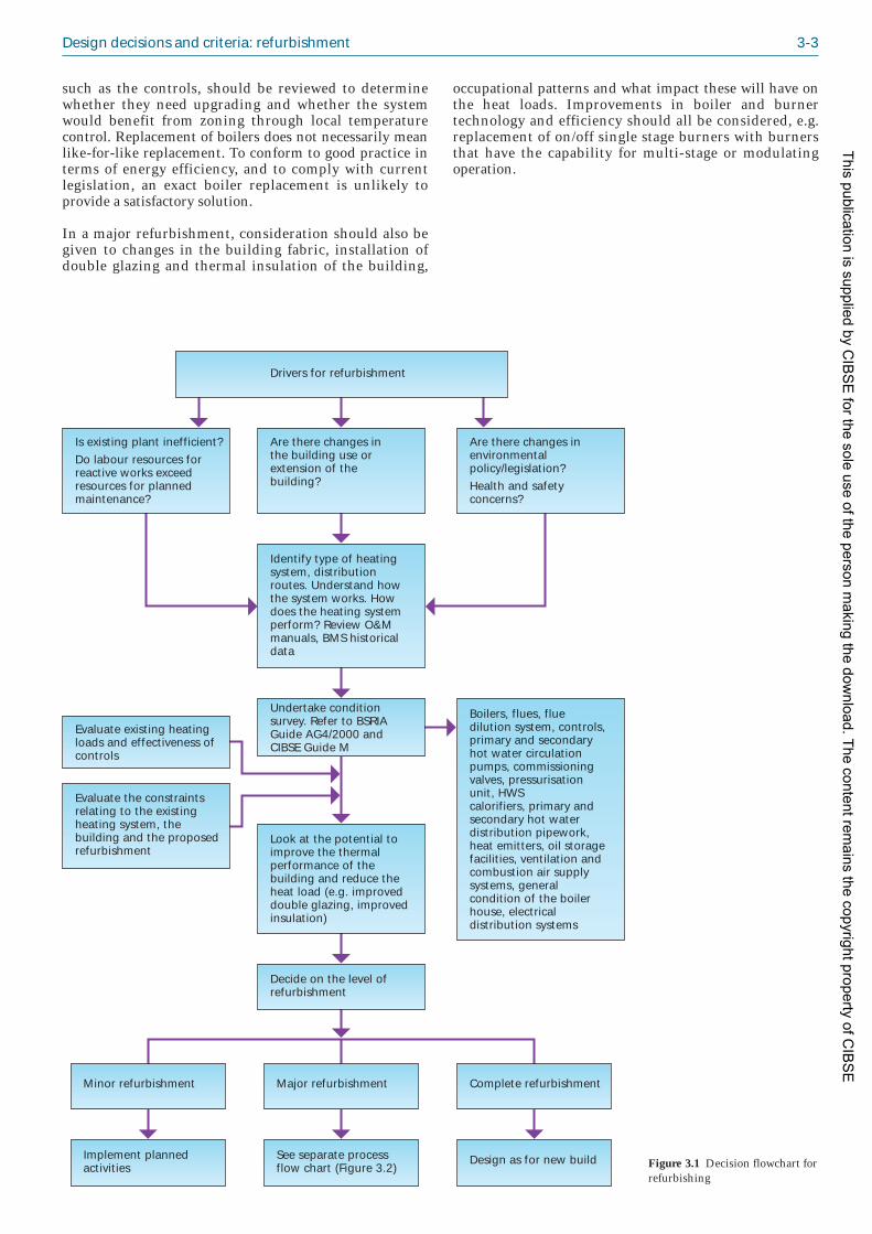
Design decisions and criteria: refurbishment 3-3
such as the controls, should be reviewed to determinewhether they need upgrading and whether the systemwould benefit from zoning through local tempera turecontrol. Replacement of boilers does not necessarily meanlike-for-like replacement. To conform to good practice interms of energy efficiency, and to comply with currentlegislation, an exact boiler replacement is unlikely toprovide a satisfactory solution.
In a major refurbishment, consideration should also begiven to changes in the building fabric, installation ofdouble glazing and thermal insulation of the building,
occupational patterns and what impact these will have onthe heat loads. Improvements in boiler and burnertechnology and efficiency should all be considered, e.g.replacement of on/off single stage burners with burnersthat have the capability for multi-stage or modulatingoperation.
Drivers for refurbishment
Decide on the level of refurbishment
Major refurbishment
See separate process flow chart (Figure 3.2)
Implement planned activities
Design as for new build
Minor refurbishment Complete refurbishment
Look at the potential toimprove the thermalperformance of thebuilding and reduce theheat load (e.g. improveddouble glazing, improvedinsulation)
Undertake condition survey. Refer to BSRIA Guide AG4/2000 and CIBSE Guide M
Boilers, flues, fluedilution system, controls, primary and secondary hot water circulation pumps, commissioning valves, pressurisation unit, HWScalorifiers, primary andsecondary hot water distribution pipework,heat emitters, oil storage facilities, ventilation andcombustion air supplysystems, generalcondition of the boilerhouse, electrical distribution systems
Are there changes inthe building use or extension of the building?
Are there changes inenvironmental policy/legislation?Health and safetyconcerns?
Is existing plant inefficient?Do labour resources forreactive works exceedresources for plannedmaintenance?
Evaluate the constraintsrelating to the existing heating system, the building and the proposed refurbishment
Identify type of heatingsystem, distribution routes. Understand how the system works. How does the heating system perform? Review O&M manuals, BMS historical data
Evaluate existing heating loads and effectiveness ofcontrols
Figure 3.1 Decision flowchart forrefurbishing
This publication is supplied by CIB
SE
for the sole use of the person making the dow
nload. The content remains the copyright property of C
IBS
E

3-4 Non-domestic hot water heating systems
3.3.3 Complete refurbishment
This may involve a complete redesign and replacement ofthe heating system and all associated works in the boilerplant room in addition to replacing the complete heatdistribution system and heat emitters. Refurbishment ofthis nature may be undertaken as part of a major refur -bishment of the building structure, when the building isunoccupied.
The key decisions that need to be made when consideringthe extent of refurbishment are shown in Figure 3.1 andthe process of major refurbishment is illustrated in Figure3.2.
3.4 ConstraintsThe design of the existing building, including access toelements of the existing heating system and the size and
layout of the plant space, may impose some constraints onthe design of a replacement system. For example, the useof some low carbon technologies may require a largerfootprint than traditional heating plant, and additionalspace for fuel storage and handling. The existing designmay also have implications for the installation, particular -ly relating to access to carry out the work or maintenanceof the installation. The following issues may need to beconsidered, under the various headings listed:
3.4.1 Design
Possible constraints on design include:
— lack of information on the existing heating system;e.g. layout schematics of heating plant, primaryand secondary hot water distribution systems,O&M manuals, oil, gas and electricity utility bills
— lack of information on the operation of theexisting heating system and control strategies
Commission and handover
Fill, test and chemicallydose system
Major refurbishment
Re-evaluate options
Continuous monitoring, maintenance and targeting
Install new plant andauxiliary items; upgrade or replace controls
Drain sections of heatdistribution system toallow removal of existing equipment
Prepare M&E designspecification based onpreferred option/tenderdocumentation; appointcontractors
Include client in discussions. Ensureinvolvement of building services engineer, building operators, maintenance staff
Determine use of building and new heating loads Review existing controls
Identify and evaluateoptions for plantreplacement, auxiliary items and controls. Size replacement plant
Consider changes to the building fabric,installation of doubleglazing, thermalinsulation of building
Consider statutoryrequirements, e.g.Health and Safety at Work Act, CDM Regs., COSHH Regulations that have to be complied with
Has whole life cycle cost been considered?
Consider use of zoning to enable flexibility of building use; determine appropriate zoning requirement
No
Establish local authority requirements for planning with regard to use of low or zero carbon technolo-gies, e.g. CHP, condensing boilers, biomass boilers, solarthermal systems Yes
Does design specification comply with legislation, efficiency requirements etc?
Figure 3.2 Process flow chart formajor refurbishment
This publication is supplied by CIB
SE
for the sole use of the person making the dow
nload. The content remains the copyright property of C
IBS
E

Design decisions and criteria: refurbishment 3-5
— lack of design data for original plant equipment (tobe interfaced with new plant)
— lack of information relating to the building fabricthermal properties and existing heating loads
— compatibility issues of new plant with existingplant and utility supplies
— compatibility issues of new plant with existingcontrols (e.g. BMS)
— corporate guidelines/image may require highefficiency and/or low carbon technologies
— existing heating system designed for non-condensing boiler plant; may require substantialdesign changes for condensing boiler application.
3.4.2 Costs
Likely cost constraints include:
— consultancy/design cost limit
— capital expenditure limit
— operational costs: energy, service and maintenance.
3.4.3 Environmental
Various environmental requirements may apply:
— position of flue terminal/discharge of combustiongases; in cases where a flue discharge can only besited at low level, a fanned flue dilution systemmay be required (this may not be practical due tospace constraints within the plant room)
— presence of asbestos (will require removal orencapsulation)
— compliance with the Building RegulationsApproved Document L2B(2) and the Chimneyheights memorandum(3) with respect to separationdistances from the flue terminal to an opening orboundaries
— location of the plant room and the ability todischarge flue gases and the removal of condensate
— boiler emissions (NOx, CO, CO2): legislation mayrequire plant with low emissions*
— renewable energy and carbon reduction tech -nologies (refer to local authority planning policy)
— noise (external limits apply).
3.4.4 Space and access
The following may affect the installation of the replace -ment system:
— isolation of existing services
— access for safe removal of redundant equipment
— routing of flues, pipes, ducts etc.
— access for plant equipment installation
— access for inspection
— access for maintenance
— access for repair
— access for replacement
— access for future plant removal/replacement.
3.4.5 Space for plant
Space considerations include the following:
— plant rooms
— vertical riser space for ducts and pipes
— floor voids
— ceiling voids.
3.4.6 Weight loading
The loadings imposed by plant need to be considered asfollows:
— plant room floors
— ceilings
— roofs
— walls.
3.4.7 Constraints due to installationwork
Refurbishment works may be limited because of thefollowing:
— building remains occupied during refurbishment
— restricted working hours
— co-ordination with work on building fabric
— reducing the impact of noise and dust onoccupants.
3.4.8 Safety
The following issues should also be considered
— noise
— fumes
— vibration
— surface temperatures
— rotating machinery
— air quality (Clean Air Act(4))
— use of hazardous materials.
3.5 Statutory regulations andguidance
The statutory regulations and guidance for new buildingsdiscussed in section 2 apply to any form of refurbishment.
* If project is subject to assessment under BREEAM or equivalent thenthe score may be affected
This publication is supplied by CIB
SE
for the sole use of the person making the dow
nload. The content remains the copyright property of C
IBS
E

3-6 Non-domestic hot water heating systems
In addition, the following also applies to any refurbish -ment project:
— Building Regulations Approved Document L2B:Conservation of fuel and power in existing buildingsother than dwellings(2).
3.6 Identification of existingheating system types
There are various types of heating distribution systemsthat have been installed in buildings over the last fewdecades. These are:
— one-pipe systems (very old systems)
— two-pipe systems (direct return)
— two-pipe systems (reversed return)
— pumped primary/pumped secondary systems(direct return)
— manifold systems.
Some are easily adaptable to adequate zoning and controls,others are less adaptable whilst there are some systems forwhich the only economical or practical solution isreplacement.
It is likely that when the new load is determined, existingemitters may prove to be capable of meeting the designload at reduced temperature. This is particularly beneficialwhere condensing boilers are used as replacements, seesection 3.9.
3.6.1 One-pipe systems
In this arrangement, the emitters are served by a singleLTHW pipe loop or several loops in parallel, see Figure3.3(a). The water flow temperature drops progressivelythrough each radiator. As a result, a major disadvantage ofthis arrangement is that the first radiator gets hotter thanthe second and the last radiator in the series will beconsiderably cooler. Any number of radiators may befitted to a one-pipe system, but the greater the number ofradiators, the greater the temperature drop across thesystem. Control of one-pipe systems requires the use ofbypasses with 3-port control valves. For such systems thepipework distribution infrastructure will be sized for thetotal circuit.
3.6.2 Two-pipe systems (direct return)
Two-pipe systems are the most common wet system foundin commercial buildings. Figure 3.3(b) shows a two-pipesystem with direct return and Figure 3.3(c) shows a
Return
Flow
(a) One-pipe system
Heatsource
Load Load Load
Return
Flow
(b) Two-pipe system (direct return)
Heatsource Load Load Load
Return
Return
Flow
(c) Two-pipe system (reverse return)
Heatsource
Load Load Load
(d) Pumped primary/pumped secondary system (direct return)
Load Load
Primary flow
Secondary return
Secondary flow
Load
Primary return
Note: bypasses not shown
Heatsource
Return
ManifoldManifoldFlow
(e) Manifold system
LoadLoad Load
Heatsource
Figure 3.3 Diagram illustrating the different configurations of heating systems
This publication is supplied by CIB
SE
for the sole use of the person making the dow
nload. The content remains the copyright property of C
IBS
E
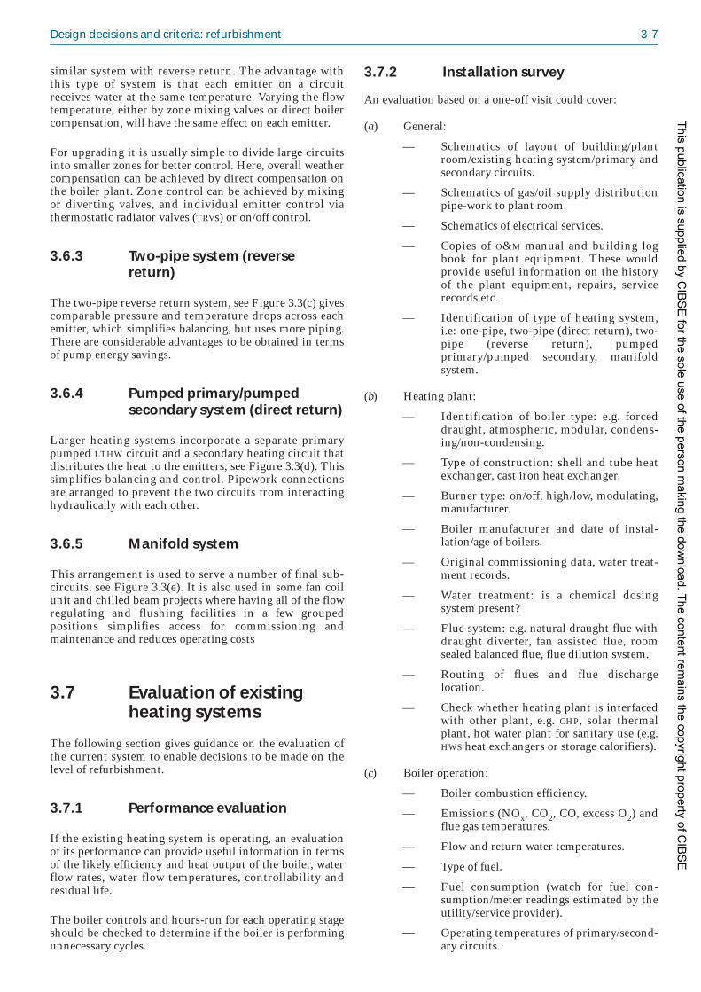
Design decisions and criteria: refurbishment 3-7
similar system with reverse return. The advantage withthis type of system is that each emitter on a circuitreceives water at the same temperature. Varying the flowtemperature, either by zone mixing valves or direct boilercompen sation, will have the same effect on each emitter.
For upgrading it is usually simple to divide large circuitsinto smaller zones for better control. Here, overall weathercompensation can be achieved by direct compensation onthe boiler plant. Zone control can be achieved by mixingor diverting valves, and individual emitter control viathermostatic radiator valves (TRVs) or on/off control.
3.6.3 Two-pipe system (reversereturn)
The two-pipe reverse return system, see Figure 3.3(c) givescomparable pressure and temperature drops across eachemitter, which simplifies balancing, but uses more piping.There are considerable advantages to be obtained in termsof pump energy savings.
3.6.4 Pumped primary/pumpedsecondary system (direct return)
Larger heating systems incorporate a separate primarypumped LTHW circuit and a secondary heating circuit thatdistributes the heat to the emitters, see Figure 3.3(d). Thissimplifies balancing and control. Pipework con nectionsare arranged to prevent the two circuits from interactinghydraulically with each other.
3.6.5 Manifold system
This arrangement is used to serve a number of final sub-circuits, see Figure 3.3(e). It is also used in some fan coilunit and chilled beam projects where having all of the flowregulating and flushing facilities in a few groupedpositions simplifies access for commissioning andmaintenance and reduces operating costs
3.7 Evaluation of existingheating systems
The following section gives guidance on the evaluation ofthe current system to enable decisions to be made on thelevel of refurbishment.
3.7.1 Performance evaluation
If the existing heating system is operating, an evaluationof its performance can provide useful information in termsof the likely efficiency and heat output of the boiler, waterflow rates, water flow temperatures, controllability andresidual life.
The boiler controls and hours-run for each operating stageshould be checked to determine if the boiler is performingunnecessary cycles.
3.7.2 Installation survey
An evaluation based on a one-off visit could cover:
(a) General:
— Schematics of layout of building/plantroom/existing heating system/primary andsecondary circuits.
— Schematics of gas/oil supply distributionpipe-work to plant room.
— Schematics of electrical services.
— Copies of O&M manual and building logbook for plant equipment. These wouldprovide useful information on the historyof the plant equipment, repairs, servicerecords etc.
— Identification of type of heating system,i.e: one-pipe, two-pipe (direct return), two-pipe (reverse return), pumpedprimary/pumped secondary, manifoldsystem.
(b) Heating plant:
— Identification of boiler type: e.g. forceddraught, atmospheric, modular, condens -ing/non-condensing.
— Type of construction: shell and tube heatexchanger, cast iron heat exchanger.
— Burner type: on/off, high/low, modulating,manufacturer.
— Boiler manufacturer and date of instal -lation/age of boilers.
— Original commissioning data, water treat -ment records.
— Water treatment: is a chemical dosingsystem present?
— Flue system: e.g. natural draught flue withdraught diverter, fan assisted flue, roomsealed balanced flue, flue dilution system.
— Routing of flues and flue dischargelocation.
— Check whether heating plant is interfacedwith other plant, e.g. CHP, solar thermalplant, hot water plant for sanitary use (e.g.HWS heat exchangers or storage calorifiers).
(c) Boiler operation:
— Boiler combustion efficiency.
— Emissions (NOx, CO2, CO, excess O2) andflue gas temperatures.
— Flow and return water temperatures.
— Type of fuel.
— Fuel consumption (watch for fuel con -sumption/meter readings estimated by theutility/service provider).
— Operating temperatures of primary/second -ary circuits.
This publication is supplied by CIB
SE
for the sole use of the person making the dow
nload. The content remains the copyright property of C
IBS
E
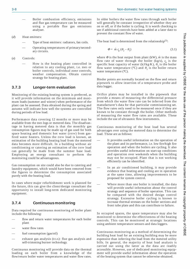
3-8 Non-domestic hot water heating systems
— Boiler combustion efficiency, emissionsand flue gas temperature can be measuredusing a portable flue gas emissionsanalyser.
(d) Heat emitters:
— Type of heat emitters: radiators, fan coils.
— Operating temperatures of primary/second -ary circuits.
(e) Controls:
— How is the heating plant controlled inrelation to any cooling plant, i.e. BMS orboiler controls, individual zone controls,weather compensation. Obtain controlstrategy for heating plant.
3.7.3 Longer-term evaluation
Monitoring of the existing heating system is preferred, asit will provide information on the minimum and maxi -mum loads (summer and winter) when performance of theplant can be assessed. Data obtained during the spring andautumn will indicate how well the systems are controlledduring periods of low load.
Performance data covering 12 months or more may beavailable from the BMS logs or metered data. The disadvan -tage in having metered data is that the monthly gasconsumption figures may be made up of gas used for bothspace heating and domestic hot water (DHW) from gas-fired water heaters. Unless the DHW load is known, anestimation of the building heating load from the metereddata becomes more difficult. In a building without airconditioning or catering an estima tion of the DHW loadcan generally be made from the summer base load.Employing an energy consultant to perform themonitoring could be advantageous.
Gas consumption on site could also be due to catering andlaundry equipment, which would have been removed fromthe figures to determine the consumption associatedpurely with the heating load.
In cases where major refurbishment work is planned forthe future, this can give the client/design consultant theopportunity to install long-term dedicated monitoringequipment.
3.7.4 Continuous monitoring
Data required for continuous monitoring of boiler plantinclude the following:
— flow and return water temperatures for each boilerplant
— water flow rates
— fuel consumption (gas/oil)
— exhaust gas analysis (EGA): flue gas analysis andself-trimming burner technology.
Continuous monitoring will provide data on the thermalloading on each boiler from a knowledge of theflow/return boiler water temperatures and water flow rates.
In older boilers the water flow rates through each boilerwill generally be constant irrespective of whether they areon or off, or if the boiler is cycling. It is worth checking tosee if additional controls have been added at a later date toprevent the constant flow of water.
The heat load is determined from the relationship(5):
Φ = m· cp (θ2 – θ1) (3.1)
where Φ is the heat output from plant (kW), m· is the massflow rate of water through the boiler (kg/s), cp is thespecific heat capacity of water (kJ/kg·K), θ2 is the boilerflow water temperature (°C) and θ1 is the boiler returnwater temper ature (°C).
Binder points are normally located on the flow and returnpipework to allow insertion of a temperature probe anddata logger.
Orifice plates may be installed in the pipework thatprovide a means of measuring the differential pressurefrom which the water flow rate can be inferred from themanufacturer’s data for that particular commis sioning set.The flow rates only need to be measured once if they areknown to be constant through the boiler. Other methodsof measuring the water flow rates are available. Theseinclude the use of ultrasonic flow instruments.
Continuous monitoring of the heat load has severaladvantages over using the metered data to determine theload. These are as follows:
— It provides useful information on the operation ofthe plant and its performance, i.e. low fire/high fireoperation and when the boilers are cycling. It alsoprovides useful information on start-up conditionsand operation over weekends when the buildingmay not be occupied. Plant that is not workingefficiently can be identified.
— In an air conditioned building, it may provideevidence that heating and cooling are in operationat the same time, allowing improvements to beproposed for system control.
— Where more than one boiler is installed, the datawill provide useful information about the controlstrategy and sequence of boiler operation. This canbe compared with the desired design controlstrategy. Excessive boiler cycling is known toincrease thermal stresses on the boiler sections andfront tube plate and this can contribute to failure.
In occupied spaces, the space temperature may also bemonitored to determine the effectiveness of the heatingcontrols. This can be monitored at strategic locationsusing ambient temperature sensors and data loggers.
Continuous monitoring as a method of determining thebuilding heat load for an existing building may be moreexpensive than inferring the load from the metered utilitybills. In general, the majority of heat load analysis iscarried out using the latter as the data are readilyaccessible. However, use of dedicated monitoring equip -ment will provide useful information about the operationof the heating system that cannot be otherwise obtained.
This publication is supplied by CIB
SE
for the sole use of the person making the dow
nload. The content remains the copyright property of C
IBS
E

Design decisions and criteria: refurbishment 3-9
3.7.5 Monitoring interval
The frequency of monitoring will depend on thefrequency of the load variations. Boilers on a high/lowcontrol strategy will normally start-up on high fire from acold start, modulate to low fire, then cycle on/off on lowfire once the heat load is satisfied. It will be necessary tolog the data at one-minute intervals to assess the controlstrategy during the cyclic mode of operation.
3.7.6 Data analysis
The data should be analysed by comparing the constantflow load data (i.e. water flow rates, flow/return temper -atures, flue gas temperatures, combustion readings, fuelconsumption) with design/commissioning data andascertaining whether there is a difference of more than10–20%. Constant flow data can be obtained when theheating plant is operating on high or low fire.
Calculate the heating load from measurements of thewater flow rate and temperature difference when the boileris working at full load conditions (high fire) and comparewith the nominal design heat output of the plant.
Assess the operation of the plant and how well theyrespond to meeting high and low loads. For example, inmid-winter, how many boilers are on? Do they rapidlycycle on/off?
Determine the total heating load (by summation of themeasured heating load profiles where there is more thanone boiler) and compare with the combined nominal heatoutput of the plant. This will indicate by how much theboilers are oversized. For example, in one particularbuilding, three identical boilers were installed butmonitoring showed that only two were ever needed.
3.7.7 Site condition survey
The objectives of a site condition survey are as follows:
— To inform client/design consultant of the con -dition of the heating installation and recommendoptions for their refurbishment.
— To describe the condition of the plant equipment.
— To comment on the equipment surveyed, e.g.general condition, expected life and performance.
— To provide an asset list of building servicesequipment.
Information required as part of a survey includes thefollowing:
— schematics of layout of building/plant room/existingheating system/primary and secondary circuits
— schematics of gas/oil supply distribution pipe-work to plant room
— schematics of electrical services
— condition of services
— size/rating of plant
— access to plant (removal and replacement)
— capacity of services (gas, fuel oil, electricity, water)
— condition of building fabric (note effects of defectsof fabric and plant).
Plant items to be examined include the following:
(a) Heating plant
— boilers and boiler insulation
— other heat generating plant e.g. CHP, heatpumps
— flues, flue dilution system
— hot water circulation pumps (secondaryand primary)
— commissioning valves, isolation valves
— primary and secondary hot water distri -bution pipework, pipework joints
— pipework insulation
— controls
— sensors
— oil/LPG storage facilities
— ventilation and combustion air supplysystems
— fuel distribution services (gas and oil) andmeters
— chemical water treatment dosing plant
— general condition of the boiler house
— burner and controls.
(b) DHW services:
— oil or gas fired water heaters
— HWS calorifiers
— storage cylinders
— plate heat exchangers
— pressurisation unit
— header tank
— valves.
(c) Other:
— heat emitters
— zone controls
— building management system (BMS)
— electrical distribution system
— catering and laundry equipment (fuelconsumption).
Prior to carrying out the site survey, as much informationas possible should be collected, e.g. from the building logbook, record drawings, O&M manuals, commissioningrecords, and maintenance data. The survey shouldproduce details of the equipment and its condition, asfollows:
— manufacturer
— model
— size
This publication is supplied by CIB
SE
for the sole use of the person making the dow
nload. The content remains the copyright property of C
IBS
E

3-10 Non-domestic hot water heating systems
— output
— age and condition
— service history.
A rating scheme for plant condition should be devised,e.g:
— ‘Excellent’: above average condition for age
— ‘Average’: average condition for age
— ‘Poor’: below condition average for age
— ‘U/S’: unservicable.
When carrying out a site condition survey, particularattention should be paid to the following:
— damaged or missing plant items
— corrosion (plant can be examined internally usinga endoscope)
— excessive sooting within the combustion chamber
— leaks/water stains on the welds on the front andrear tube plates of shell and tube boilers
— leaks on cast iron sectional boilers
— dangerous or unsafe equipment
— excessive noise and vibration
— excessive heat loss from boiler insulation panels
— poor performance and operation of heating plant(from monitoring data)
— items of plant not working or redundant
— whether old/damaged/broken equipment can beeconomically repaired/refurbished or has to bereplaced.
3.7.8 Personal safety
The Health and Safety at Work etc. Act(6) and subsidiaryregulations must be adhered to at all times.
Personnel involved in site conditions surveys must notundertake any tasks that are outside their areas ofcompetence, particularly in respect of oil, gas and electri -cal installations.
A risk assessment must be conducted in areas that aredeemed unsafe for inspection, e.g. where asbestos ispresent, or require entry into confined spaces orunguarded roof levels.
Condition surveys should be undertaken by independentconsultants in the presence of regular maintenance staffwho have first hand knowledge about the plant items. Noequipment should be turned on or off without a fullunderstanding of the implications of doing so.
3.8 Evaluation of heatingloads
The existing heating load in a building can be evaluatedby using any of the three methods described below:
— by calculation from first principles
— by using historical information on the annual fuelconsumption
— by long-term monitoring of the heating plant.
The methods of calculating the heat loads from firstprinciples have been described in detail in chapter 2.
3.8.1 Calculation principles
The existing total heat load can be calculated byconsidering the total fabric transmission heat loss of thebuilding, the total ventilation heat loss and the totalheating-up capacity required to compensate for the effectsof intermittent heating.
Compared to the original heating load design calculation,there may have been changes to the building structure,mechanical services, building usage etc. that would affectthe thermal performance of the building. The heat loadcan therefore be re-calculated taking into considerationthe following:
— changes to the thermal fabric of the building,particularly where extensions/refurbishment to thebuilding are made
— changes in the ventilation requirements andinfiltration levels
— changes in the internal heat gains
— changes in the occupancy pattern
— changes in building use.
3.8.2 Use of historical data
An estimate of the existing heat loads can be made frommetered data. However care is required as the gasconsumption figures may be made up of gas used for spaceheating and gas used for domestic hot water supply.
3.8.3 Long-term monitoring
Performance monitoring data obtained over a 12-monthperiod may be used to determine the heating load profiles.These will include measurement of the flow and returnwater temperatures, water flow rates and fuel consump -tion. Section 3.7.4 describes how the heat load profiles canbe determined from the measured parameters.
3.9 Reducing energyconsumption
Energy savings opportunities should be examined prior torefurbishment of the existing heating system. These mayinclude the following:
— improving the thermal performance of thebuilding through improved insulation and windowreplacement
— performing a pressure test and infra-red survey todetermine infiltration rates through the building
This publication is supplied by CIB
SE
for the sole use of the person making the dow
nload. The content remains the copyright property of C
IBS
E

Design decisions and criteria: refurbishment 3-11
fabric; reduce the infiltration rates throughimprovements in the building fabric if necessary
— selecting efficient plant, e.g. condensing boilers,and a direct weather compensation strategy
— installing heat recovery on ventilation plant (if notalready installed)
— incorporating zone controls
— minimising the heat losses from boilers, pipeworkand storage.
— considering direct fired condensing HWSgenerators and/or solar water heating so that themain boilers (if condensing type) can maximiseefficiency in the condensing mode.
3.10 Options for refurbishmentusing low carbontechnologies
3.10.1 Solar thermal technology
Solar thermal technology makes use of solar collectors forharnessing solar energy for heating hot water. The basicform of operation involves the transfer of solar irradiationenergy in the form of heat to the solar circuit fluid. Thecircuit fluid is usually pumped around the system but maybe driven by natural convention, transferring the heatenergy to the storage cylinder, indirectly via a coil. Thecircuit fluid may be water from the storage cylinder or, inpumped systems, a separate heat transfer circuitcontaining anti-freeze (usually a water/glycol mixture) anda corrosion inhibitor. This is usually a coil of copper orstainless steel within a storage cylinder.
Collectors for solar thermal systems can be any of thefollowing:
— formed plastic plate collectors such as poly -propylene
— glazed flat plate collectors
— evacuated tube collectors.
The collector area required will be dictated by theefficiency of the system and hence will depend on the typeselected, e.g. for the same output a flat plate collectorwould need a greater area than an evacuated tube collector.The efficiency of the system is dependent upon the heatloss from the collector surface which is a function of thethermal gradient between the surface temperature of thecollector absorber (glazed flat plate type), or temperatureof the heat transfer fluid exiting the collector (evacuatedtube type), and the ambient air. The efficiency of thecollector decreases as the ambient temperature falls orwhen the collector temperature rises. The efficiency of thecollector can be improved by increasing its insulationeither by sealing the unit in glass, e.g. glazed flat platecollectors or by providing a vacuum seal, e.g. evacuatedtube collectors.
Collectors are generally arranged in arrays. Arrays can belocated differently to maximise the incident irradiation. Ingeneral only one array is used and it is placed in the
optimum position. Multiple arrays of solar collectors areused when a more even heat gain is required throughoutthe day, roof space is limited or where one location is notideal.
The choice of the collector depends upon the heatingrequirements and the conditions where it is installed.
3.10.1.1 Applications in the commercial andindustrial sectors
Solar thermal technology can be applied in various appli -cations associated with commercial heating systems.These include:
— heating systems: integration with commercialboilers and direct-fired water heaters to producedomestic hot water
— leisure centres: heating swimming pools.
Solar irradiation will not always supply hot water at timesof demand and there may be periods where there could beno solar contribution. Supplementary heating systems arenormally integrated as part of the solar hot water system toensure that hot water demand is always satisfied.
Figure 3.4 shows an application involving the use of asolar thermal system with a gas fired condensing boiler toprovide LTHW. Dedicated boilers can also be used tosupplement the production of hot water from the solarthermal system, see Figure 3.5. Alternatively hot waterfrom an existing primary heating system can be divertedvia a pump and valve arrangement to the solar thermalsystem.
3.10.1.2 Interfacing solar thermal systems
The main issues to be considered when interfacing solarthermal technology to existing buildings are given below.
Sizing
The solar thermal cylinder should be sized on the dailyhot water demand for the property. The solar collectorarray should then be sized to provide a proportion of thedaily hot water load (typically up to 50% is an industrynorm).
Robust historical information on the hot water load forthe building is required for accurate matching of demandand the solar thermal solution.
Where solar thermal systems are used with boilers, thesolar cylinder could replace an existing calorifer. Thiswould be a twin-coil solar cylinder with the lower coilbeing served by the solar collector array and the top coilby the boilers.
It is essential that the top portion of the cylinder served bythe boilers is of sufficient volume to provide sufficient hotwater to meet demand during periods of low solar gain;e.g. if the load is 900 litres then the top coil of cylindermust serve a volume of 900 litres in order to meet demand.
Ensure that pipework is sized appropriately for therequired flow rates.
This publication is supplied by CIB
SE
for the sole use of the person making the dow
nload. The content remains the copyright property of C
IBS
E

3-12 Non-domestic hot water heating systems
HWSflow
Expansionvessel
Solarpumpstation
Isolationvalves
Gas firedheater
Thermalstore
Solar control panel
Non-returnvalve
Expansionrelief valve
Pressurelimiting line andstrainer valve
Temp/pressurerelief valve
Solarexpansionvessel
Cold watersupply
Stopcock
Non-returnvalve
Hotwateroutlets
Secondaryreturn pump
HWSreturn
Commissionand fillingvalve
Draincock
Figure 3.5 Solar thermal (HWS)with dedicated hot water boiler(courtesy of Baxi CommercialDivision)
LTHWflow
LTHWreturn
Pressurisationunit
EV
Solarpumpstation
Solarexpansionvessel
Isolationvalves
Condensingboiler
Thermalstore
Solar control panel
LTHW load
Temp/pressurerelief valve
Figure 3.4 Solar thermal systemdesigned to provide LTHW withgas fired condensing boiler(courtesy of ArmstrongIntegrated Systems Ltd.)
This publication is supplied by CIB
SE
for the sole use of the person making the dow
nload. The content remains the copyright property of C
IBS
E

Design decisions and criteria: refurbishment 3-13
Installation
Figure 3.6 shows a typical solar collector installation(7).
Collectors should be installed at their optimumorientation and angle to maximise solar contribution, i.e.between 30° and 45° from the horizontal when facing duesouth (collectors should be installed facing due north inthe southern hemisphere).
Appropriate expansion vessels and relief valves should beinstalled on both solar and domestic hot water sides of thesystem.
Solar collectors must be covered during periods ofexposure to solar irradiation prior to the system beingfilled to prevent damage to the absorber surface due tooverheating.
The solar system should only be filled using the suppliedglycol/water mixture. It is recommended that this is alsoused for test fills due to difficulties in draining down thecollectors completely.
A destratification pump should be installed on the solarcylinder to pasteurise the water to mimimise the growth ofLegionella bacteria .
Plant room height should be considered as a twin-coilsolar cylinder would be larger than a conventionalcalorifer for a given hot water load. Plant room spacewould be required to accommodate the solar pump stationand solar heat transfer fluid expansion vessel, and wallspace for the control unit. As an alternative to a twin-coilcylinder, a single coil solar cylinder could be used to pre-heat the cold water feed into an existing calorifier but thespace would be required for the additional solar cylinder.In this case a shunt pump should be installed between thehot water in the calorifier and the solar pre-heat cylinderfor pasteurisation. Another commonly used alternative,particularly for large scale installations, is a direct cylinderwith an external plate heat exchanger.
3.10.2 Combined heat and power
Combined heat and power (CHP), is the simultaneousgeneration of usable heat and power from the same source.CHP has developed as an established technology and playsa key role in reducing CO2 emissions. These systems aremost suitable for applications where there is a significantyear-round demand for heating as well as electricity.
CHP systems are usually categorised according to the sizeof the electrical output. Each category contains a range ofsizes but the categories can be approximately defined as inTable 3.1.
Prime movers for CHP include reciprocating engines,steam turbines, gas turbines, biomass and combined cyclesystems. Fuels for CHP include natural gas, LPG, landfillgas, biogases, biodiesel, biomass and fuel cells.
At the lower end of the scale (i.e. micro, mini and smallscale CHP), reciprocating engines are mainly used. Themajority of reciprocating engines used in CHP are auto -motive or marine engines that have been adapted to runon natural gas. Such systems produce two grades of heat:high-grade heat from the engine exhaust, and low-gradeheat from the engine cooling circuits.
For medium and large scale CHP applications, gas turbinesare generally used. These are often developments of aero-engines.
In addition to the simultaneous production of heat andpower, CHP can also be used to provide cooling for air con -ditioned buildings. This process, known as ‘trigeneration’or ‘combined cooling, heat and power’ (CCHP), combinesCHP with a heat driven absorp tion chilling plant to extendthe base load heat demand in the summer months to meetcooling loads that are economic and help to reduce CO2emissions. Trigeneration makes effective use of heat forlarge air conditioned buildings that were previouslyunsuitable for CHP alone. An example of such a system isshown in Figure 3.7.
Examples of typical applications for CHP in thecommercial/industrial sector include:
— hospitals
— hotels
— leisure centres.
Retrofitting CHP systems to existing heating systems
The installation of the CHP may be part of a majorrefurbishment or complete refurbishment. In the case of amajor refurbishment, the process flowchart in Figure 3.2should be followed. In cases where complete refurbish mentof the heating system is to take place, the design guidanceas for new-build should be followed, see chapter 2.
Some of the main issues to be considered when retrofittingCHP systems to heating systems are:
— feasibility of CHP
Figure 3.6 Solar panels mounted on a flat roof (courtesy of BaxiCommercial Division)
Table 3.1 Classification of CHP systems(source: BSRIA BG2/2007(8)
Description Electricity output
Micro CHP < 5 kWe*
Mini CHP 5 to 500 kWe
Small scale CHP 500 kWe to 5 MWe
Medium scale CHP 5 to 50 MWe
Large scale CHP > 50 MWe
* kWe refers to the electricity output of CHP
This publication is supplied by CIB
SE
for the sole use of the person making the dow
nload. The content remains the copyright property of C
IBS
E
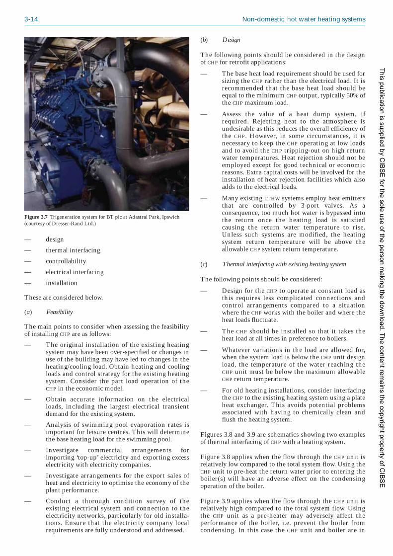
3-14 Non-domestic hot water heating systems
— design
— thermal interfacing
— controllability
— electrical interfacing
— installation
These are considered below.
(a) Feasibility
The main points to consider when assessing the feasibilityof installing CHP are as follows:
— The original installation of the existing heatingsystem may have been over-specified or changes inuse of the building may have led to changes in theheating/cooling load. Obtain heating and coolingloads and control strategy for the existing heatingsystem. Consider the part load operation of theCHP in the economic model.
— Obtain accurate information on the electricalloads, including the largest electrical transientdemand for the existing system.
— Analysis of swimming pool evaporation rates isimportant for leisure centres. This will determinethe base heating load for the swimming pool.
— Investigate commercial arrangements forimporting ‘top-up’ electricity and exporting excesselectricity with electricity companies.
— Investigate arrangements for the export sales ofheat and electricity to optimise the economy of theplant performance.
— Conduct a thorough condition survey of theexisting electrical system and connection to theelectricity networks, particularly for old installa -tions. Ensure that the electricity company localrequirements are fully understood and addressed.
(b) Design
The following points should be considered in the designof CHP for retrofit applications:
— The base heat load requirement should be used forsizing the CHP rather than the electrical load. It isrecommended that the base heat load should beequal to the minimum CHP output, typically 50% ofthe CHP maximum load.
— Assess the value of a heat dump system, ifrequired. Rejecting heat to the atmosphere isundesirable as this reduces the overall efficiency ofthe CHP. However, in some circumstances, it isnecessary to keep the CHP operating at low loadsand to avoid the CHP tripping-out on high returnwater temperatures. Heat rejection should not beemployed except for good technical or economicreasons. Extra capital costs will be involved for theinstallation of heat rejection facilities which alsoadds to the electrical loads.
— Many existing LTHW systems employ heat emittersthat are controlled by 3-port valves. As aconsequence, too much hot water is bypassed intothe return once the heating load is satisfiedcausing the return water temperature to rise.Unless such systems are modified, the heatingsystem return temperature will be above theallowable CHP system return temperature.
(c) Thermal interfacing with existing heating system
The following points should be considered:
— Design for the CHP to operate at constant load asthis requires less complicated connections andcontrol arrangements compared to a situationwhere the CHP works with the boiler and where theheat loads fluctuate.
— The CHP should be installed so that it takes theheat load at all times in preference to boilers.
— Whatever variations in the load are allowed for,when the system load is below the CHP unit designload, the temperature of the water reaching theCHP unit must be below the maximum allowableCHP return temperature.
— For old heating installations, consider interfacingthe CHP to the existing heating system using a plateheat exchanger. This avoids potential problemsassociated with having to chemically clean andflush the heating system.
Figures 3.8 and 3.9 are schematics showing two examplesof thermal interfacing of CHP with a heating system.
Figure 3.8 applies when the flow through the CHP unit isrelatively low compared to the total system flow. Using theCHP unit to pre-heat the return water prior to entering theboiler(s) will have an adverse effect on the condensingoperation of the boiler.
Figure 3.9 applies when the flow through the CHP unit isrelatively high compared to the total system flow. Usingthe CHP unit as a pre-heater may adversely affect theperformance of the boiler, i.e. prevent the boiler fromcondensing. In this case the CHP unit and boiler are in
Figure 3.7 Trigeneration system for BT plc at Adastral Park, Ipswich(courtesy of Dresser-Rand Ltd.)
This publication is supplied by CIB
SE
for the sole use of the person making the dow
nload. The content remains the copyright property of C
IBS
E

Design decisions and criteria: refurbishment 3-15
parallel and the internal pump in the CHP is controllingthe flow rate through the unit. Operators need to bemindful of the pressure drop across the boiler because thepump within the CHP unit would need to overcome theloss.
(d) Controllability
Control options for CHP to avoid unnecessary tripping outor heat dumping may include the following:
— Reducing the boiler flow temperature: where it isuneconomical to modify the control strategy forthe existing heating system, to provide adequatecontrol of the LTHW return, it may be acceptable toreduce the boiler flow temperature setting. Thismay be achieved by setting the boiler flowthermostat to, say, 2 °C above the CHP maximumreturn tempera ture. This will result in the boilerbecoming disabled when the system returntemperature reaches the boiler set-point flowtemperature. This will allow the CHP to provide theentire base heating load.
— Controlling the boiler firing according to the heatingsystem return temperature: consider the feasibility ofcontrolling the boiler firing sequence. This willdepend on the capabilities of the differentburner/boiler combinations and whether theburner is on/off or modulating. For example, inone installation, the boilers had 2-stage burnerswith thermostats set to 82 °C. These weresequenced to the system return temperature suchthat, at a return temperature of 79 °C, one boilerwas switched off. As the return temperaturereached 82 °C both boilers were switched off. Thiscontrol strategy would enable the CHP to run forlong periods without shutting down.
— Use of 2-port control valves: consider the advantagesand disadvantages of 2-port and 3-port valvecontrol systems, and the hydraulic and tempera -ture effects of these systems.
— Control using a BMS: consider the use of the BMS forsequencing the CHP and boilers. Correct operationwill depend on close temperature differentials. Itwill be necessary to use the return temperaturedetector in the CHP as the BMS referencing point for
sequencing the CHP unit and boiler firingsequence.
(e) Electrical interfacing
Electrical installation should comply with the EnergyNetworks Association (ENA) engineering recommen -dations G59/1(9) and G83/1(10) and the IEE WiringRegulations (BS 7671: Requirements for electricalinstallations(11)).
G59/1: Recommendations for the connection of embeddedgenerating plant to the Public Electricity Suppliers distributionsystems(9) relates to the connection of an embeddedgenerating plant to public electricity suppliers’ distri -bution system where the connection is to systems at orbelow 20 kV and the output of the generating plant is upto 5 MW.
G83/1: Recommendations for the connection of small scaleembedded generators (up to 16 A per phase) in parallel withpublic low-voltage distribution networks(10) provides guidanceon the technical requirements for connecting small-scale(i.e. rated up to and including 16 A per phase, single ormulti-phase, 230/400 V AC) embedded generators inparallel with public low-voltage distribution networks.
(f) Installation
The exhaust system should be installed in accordance withthe British Gas publication IM/17: Code of Practice forNatural Gas Fuelled Spark Ignition and Dual-FuelEngines(12). Refer also to BS 6644: Specification forinstallation of gas-fired hot water boilers of rated inputs between70 kW (net) and 1.8 MW (net) (2nd and 3rd family gases)(13)
and the Clean Air Act 1993(4) for the location and heightof flue.
The gas supply pipework should conform to IGE/UP/10:Installation of flued gas appliances in industrial and commercialpremises(14). The completed pipework should be painted toidentify its purpose in accordance with BS 1710:Specification for identification of pipelines and services(15).
Combustion and ventilation air requirements should be inaccordance with BS 5410-2: Code of Practice for Oil Firing.
Heating circuit
DHWcircuit
Low lossheaderBoiler
CHP
Heating circuit
Low lossheaderBoiler
CHP
Figure 3.8 CHP installation with non-condensing > 125 kW (source: Baxi-SenerTec UK)
Figure 3.9 CHP installation with condensing boiler <100 kW (source:Baxi-SenerTec UK)
This publication is supplied by CIB
SE
for the sole use of the person making the dow
nload. The content remains the copyright property of C
IBS
E

3-16 Non-domestic hot water heating systems
Part 2: Installations of 45 kW and above output capacity forspace heating, hot water and steam supply services(16).
Thermal insulation to water pipework, ductworkdistributing heated air/ambient air and the exhaust systemshould be in accordance with the recommendations givenin BS 5422: Method for specifying thermal insulating materialson pipes, ductwork and equipment (in the temperature range–40 °C to +700 °C)(17), BS 5970: Code of Practice for thermalinsulation of pipework and equipment in the temperaturerange –100 °C to +870 °C(18) and BS 6700: Specification fordesign, installation, testing and maintenance of servicessupplying water for domestic use within buildings and theircurtilages(19), where applicable.
Noise in occupied spaces within the building should notexceed the appropriate noise rating (NR) curve for thebuilding/space purposes as recommended in CIBSE GuideA: Environmental design(20) and BS 8233: Sound insulationand noise reduction for buildings. Code of practice(21).
The Combined Heat and Power Quality Assurance(CHPQA) is a scheme under which registration andcertification of CHP installations is carried out inaccordance with the criterion for good quality CHP. TheCHPQA quality index is an indicator of the energyefficiency and environmental performance of a CHPscheme, relative to the generation of the same amounts ofheat and power by separate, alternative means. In order tocomply with Building Regulations Approved DocumentsL2A(22) and L2B(2) the CHP plant must achieve a minimumCHPQA quality index of 105.
Table 3.2 gives the minimum provisions for CHP units thatmust be met, in both new and existing buildings, in orderto comply with Building Regulations ApprovedDocuments L2A(22) and L2B(2).
For further information on CHP see BSRIA Guide BG2/2007: CHP for existing buildings(8).
with 50% moisture to 18 MJ/kg for prepared wood pellets.As an alternative fuel system, biomass is attractive todesigners and planners because of its apparent similarityto the combustion of gas or oil and its appeal as a renew -able and low carbon fuel. It is relatively easy to store, thuseliminating dependence on the intensity and availabilityof wind or solar irradia tion that affects other renewabletechnologies. A biomass boiler burning wood fuel isshown in Figures 3.10 and 3.11.
3.10.3.1 Pre-design considerations
Adequate space for fuel storage
Usually, storage will be in an external silo or purpose-made bunker, sited as close as possible to the boiler. BS5410-2: Code of practice for oil firing(16) proposes that fuel oilstorage should be sufficient for three weeks’ consumption.Since the calorific value (CV) of mineral oil is at least40 MJ/kg, fuel storage for biomass will be considerablylarger than that required for oil. CIBSE Guide B: Heating,ventilating, air conditioning and refrigeration(25), section1.6.3.4, suggests that solid fuel stores should be sized for100 hours at full load. Adequate access to the fuel store fordelivery lorries must be provided.
Availability of fuel
Preferably, there should be a reliable local source. If thefuel is being transported, consideration should be given tohow this affects the carbon footprint of the plant.
Figure 3.10 Biomass boiler installation with wood pellet burner atNayland Primary School, Suffolk (courtesy of Ecoenergy Ltd.(www.econergy.ltd.uk))
Figure 3.11 Wood pelletsburning in a biomass boiler(courtesy of Clyde EnergySolutions Ltd.)
Table 3.2 Summary of minimum provisions for CHP units.
Regulated area Minimum level of provision
CHPQA quality index 105
Control system Must ensure the CHP unit operates asthe lead heat generator
Metering Must be provided to measure the hoursrun, the electricity generated and thefuel supplied to the CHP unit
Efficiencies and controls See sections 2.3.8 and 2.3.9 for new for standby boilers buildings and section 3.12.2 for existing
buildings
3.10.3 Biomass boilers (solid fuel)
See also CIBSE KS10: Biomass heating(23) and CarbonTrust publication CT012: Biomass heating: a practical guidefor potential users(24). For liquid biofuel systems, see section4.2.10.
The range of solid biomass available for fuel use is large,with an accordingly wide calorific value (CV). Stemproducts (e.g. straw, grains etc.) have a gross calorific valuein the region of 14 MJ/kg. Woody biomass (the subject ofthis section) ranges from around 8 MJ/kg for wood chips
This publication is supplied by CIB
SE
for the sole use of the person making the dow
nload. The content remains the copyright property of C
IBS
E

Design decisions and criteria: refurbishment 3-17
Disposal of ash
Ash will be produced during combustion (~1% of fuel byvolume). It is non-toxic but will need to be contained onsite while awaiting disposal.
3.10.3.2 Design considerations
Boiler operating regime
Response to changes in temperature demand is muchslower than with a conventional-fuel boiler. There is aramp-up time before the boiler reaches temperature and aburn-down period at the end of each burn cycle. Unlessthe system is constant temperature, a buffer tank may berequired. Acting as a thermal store, a buffer tank willaffect the sizing and selection of the boiler. The energystored in the tank can be used to meet the peak heatdemand of the building, thus reducing the requiredcapacity of the boiler. During peak demand the energystored in the tank is depleted and at other times the boilercan re-charge the buffer tank. The selection of buffer tankand boiler will therefore depend on the user profile of thebuilding.
System temperatures
Biomass boilers usually operate at the same water-sidetemperatures as non-condensing boilers. Maintainingadequate return water temperatures is critical to ensuringboiler longevity. Many biomass boilers are steel and notresistant to corrosion associated with condensation. Withwoody biomass fuel, condensation is governed by acombination of air/fuel ratio (λ) and water content of thefuel (see Figure 3.12). The dew point temperature can beas low as 40 °C, but is more typically between 55 °C and65 °C. Consequently, biomass boilers require back-endtemperature protection. This should be taken intoconsideration if they are to be coupled with condensingboilers.
Safety
Biomass is a highly combustible fuel. Adequate precau -tions against back-burning (i.e. burning of fuel spreadingfrom the boiler combustion chamber back through thefuel delivery system) must be incorporated in any design.Current fire regulations have little to say about biomassfuel storage, but similar precautions regarding siting ofstorage silos, venting and filling should be taken as withoil storage tanks.
Chimney design
Woody biomass has a lower theoretical flame temperaturethan natural gas (around 1000 °C as opposed to 1930 °C).Therefore, the flue gases have much less buoyancy andchimneys will usually be required to overcome theresistance of the boiler combustion chamber. Fanassistance may be required. Environmental and legislativefactors may affect chimney design, e.g. if located in asmokeless zone.
Under the Clean Air Act 1993(4) it is an offence to acquirean ‘unauthorised fuel’ for use within a smoke control areaunless it is used in an ‘exempt appliance’ (i.e. exemptedfrom the controls that generally apply in smoke controlareas). Exempt appliances are those appliances (ovens,wood burners and stoves) that have been exempted byOrders under the Clean Air Act. Such appliances havebeen tested to show that they are capable of burning anunauthorised solid fuel (such as biomass) without emittingsmoke. If the biomass boiler is on the list of exemptappliances, flue height design can be as for a gas firedboiler.
Fuel delivery to the boiler
The fuel store should be as close as possible to the boiler.The delivery system must be appropriate to the fuel (e.g.an auger drive is ideal for standardised pellet sizes, butmay jam if used for irregularly-sized wood chips, forwhich a conveyor system might be more suitable). Anexample of fuel being delivered into a burner is shown inFigure 3.13.
Refer also to BS EN 303-5(27)27) ..
3.11 Whole life costs andpayback
The replacement of plant that has not already failed mayneed to be justified in terms of running cost savings andpayback period. Simple payback is a way to relate poten -tial or actual running cost savings (which may consist offuel savings, reduced maintenance and servicing costs,etc.) to capital cost, i.e:
capital cost simple payback (years) = ——————— annual running cost savings
The shorter the payback period, the more attractive willbe the proposition. Payback periods in excess of 5 years are
Dew
poi
nt t
emp
erat
ure
/ °C
70
65
60
55
50
45
40
3521·5
Air/fuel ratio1
30% moisture content
0% moisture content20% moisture content
40% moisture content
Figure 3.12 Graph showing effect of moisture content of fuel and air/fuelratio on dew point temperature (based on data from Planning andinstalling bioenergy systems(26))
This publication is supplied by CIB
SE
for the sole use of the person making the dow
nload. The content remains the copyright property of C
IBS
E

3-18 Non-domestic hot water heating systems
rarely acceptable and the payback period must always beless than the life expectancy of the plant.
Simple payback may be satisfactory for some accountingprocedures and is a good starting point. However, it doesnot take into account the changing value of money overtime. For example, the new plant may be financed by aloan, so how does interest repayments affect the paybackperiod? If the cost is paid out of the capital reserves of aclient, then interest is lost on money that could have beeninvested elsewhere, and this may also need to be takeninto account.
The solution is cumulative present value (CPV), whichrelates the value of the investment at the end of thepayback period to that at the beginning, with a specifiedinterest rate. This method gives a more accurate cal -culation of the actual payback period.
CPV = (1 – (1 + r / 100)–n) / (r / 100) (3.1)
where CPV is the cumulative present value, or the actualpayback period (years), r is the discount (interest) rate (%)and n is the number of years.
For example, a capital cost of £3000 with annual savings of£1000 would give a simple payback of 3 years, but if adiscount rate of 5% is introduced, that would be extendedto 3.33 years.
An alternative to calculation is published tables of NPV andcost benefit. These can be found, for example, inAppendix 6 of Energy Management and Operating Costs inBuildings(28).
An evaluation of life cycle costs takes much more than justpayback periods into account. Whilst payback is con -cerned with capital costs, running costs and subsequentsavings, life cycle costing also considers the embeddedenergy used in manufacturing, disposal and recycling ofthe plant. The validity of life cycle costing is alwaysdependent upon both the availability and accuracy of data.Typically, it would be used to compare the environmentalimpact for different plant performing the same function;in this case, it might be used to compare condensing andnon-condensing boilers, or condensing boilers manufac -tured from different materials. A full life cycle analysiswould include an energy analysis and an emissionsanalysis for that energy usage.
Figure 3.14 shows a generic life cycle analysis calculationprocess.
3.12 Performance criteria forreplacement boiler plant
3.12.1 Efficiency requirements forreplacement boilers
The following sections give minimum efficiency require -ments for replacement boilers in existing buildings inorder to comply with Building Regulations ApprovedDocument L2B(2) (ADL2B). The information given hereis based on that provided in the Department forCommunities and Local Government’s Non-DomesticHeating, Cooling and ventilation Compliance Guide(29). Theguidance given here applies to the following types ofboilers and excludes steam and electric boilers:
— boilers using natural gas
— boilers using liquid petroleum gas (LPG)
— oil-fired boilers (including boilers using class Dgas oil and class C2 kerosene).
Compliance with the following is required for all boilersburning liquid and gaseous fuels:
— Energy Using Products Directive (EUP)(30)
— minimum value for seasonal boiler efficiency
— minimum value for effective heat generatingseasonal efficiency.
3.12.2 Minimum requirements
For compliance with ADL2B(2), the following require -ments must be met:
(a) Each boiler (regardless of whether it is a singleboiler system or part of a multiple boiler system)should have a minimum boiler seasonal efficiency(based on gross calorific value) as calculated byequation 3.2, no worse than the relevant valuegiven in Table 3.3
Figure 3.13 Conveyor systemdelivering fuel to a biomass boiler(courtesy of Fröling GmbH)
This publication is supplied by CIB
SE
for the sole use of the person making the dow
nload. The content remains the copyright property of C
IBS
E

Design decisions and criteria: refurbishment 3-19
(b) For multiple boiler systems the minimum seasonalboiler efficiency as determined by equation 3.3should be no worse than the relevant value givenin Table 3.3
and:
(c) a minimum controls package should be adopted asgiven in Table 3.4
and:
(d) the effective heat generating seasonal efficiencyshould be not less than the relevant value in Table3.3; additional measures from Table 3.5 must beadopted to gain heating efficiency credits (seesection 3.12.3) if the boiler seasonal efficiency isless than the relevant value of the effective heatgenerating seasonal efficiency.
Definitions of terms are given in section 2.3.9.1. Equations3.2 and 3.3 are as follows:
ηs = 0.81 η30 + 0.19 η100 (3.2)
where ηs is the seasonal boiler efficiency (%), η30 is thegross boiler efficency at 30% load (%) and η100 is the grossboiler efficiency at 100% load (%).
(3.3)
where ηos is the overall seasonal boiler efficiency (%)(being a weighted average with respect to boiler output, of
ηη
os=
( )Σ
Σs R
R
Energy paybackperiod (years)
Life cycle emissions (g/kW·h)
Proportion of materials recycled (g/kW·h)
Total embodied energy of technology or site under consideration (MJ or GJ)
Total emissions of technology or site under consideration (MJ or GJ)
Energy production (kW·h or MW·h/year)
Total amount of material involved in production and disposal of technology or site under consideration (kg)
Total emissions involved in production and disposal of specific materials (g/kg of material)
Total primary energy consumption involved in production and disposal of specific materials (by fuel type if possible) (MJ/kg or MJ/m2)
Figure 3.14 Generic life cycleanalysis calculation process(courtesy of Dr Steve Lo,University of Bath)
Table 3.3 Required minimum effective heat generating seasonalefficiencies and minimum boiler seasonal efficiency for boiler systems inexisting buildings (reproduced from the Non-Domestic Heating, Coolingand Ventilation Compliance Guide(29); Crown copyright)
Fuel type Minimum effective Minimum boiler heat generating seasonal efficiency
seasonal efficiency (% gross calorific value)(% gross calorific value)
Gas (natural) 84 80
Gas (LPG) 85 81
Oil 86 82
Table 3.4 Minimum controls package for replacement boilers in existingbuildings (reproduced from the Non-Domestic Heating, Cooling andVentilation Compliance Guide(29); Crown copyright)
Minimum controls package Suitable controls
Zone controls Zone control is required only forbuildings where the floor area isgreater than 150 m2. As a mini -mum, on/off control (e.g. throughan isolation valve for unoccupiedzones) should be provided. Thisis achieved by default for a build -ing of floor area 150 m2 or less.
Demand controls Room thermostat which controlsthrough a diverter valve withconstant boiler flow watertemperature. This method ofcontrol is not suitable forcondensing boilers.
Time controls Time clock controls
This publication is supplied by CIB
SE
for the sole use of the person making the dow
nload. The content remains the copyright property of C
IBS
E

3-20 Non-domestic hot water heating systems
Table 3.5 Heating efficiency credits for measure applicable to boiler replacement in existing buildings (reproduced from the Non-Domestic Heating,Cooling and Ventilation Compliance Guide(29); Crown copyright)
Measure Heating efficiency Comments/definitioncredits % points
A Boiler oversize ≤ 20% 2 Boiler oversize is defined as the amount by which the maximum boiler heatoutput exceeds heat output of the system at design conditions, expressed as apercentage of the system heat output. For multiple boiler systems the maximumboiler heat output is the sum of the maximum outputs of all the boilers in thesystem.
B Multiple boilers 1 Where more than one boiler is used to meet the heat load.
C Sequential control of multiple 1 Applies only to multi-boiler/module arrangements. It is recommended that the boiler systems most efficient boiler(s) should act as the lead in a multi-boiler system.
D Monitoring and targeting 1 Means of identifying changes in operation or onset of faults. The credit can onlybe claimed if metering is included and a scheme for data collection is providedand available for inspection.
E (i) Thermostatic radiator valves 1 TRVs enable the building temperature to be controlled and therefore reduce (TRVs) alone. Would also apply wastage of energy. to fanned convector systems
(ii) Weather (inside/outside 1.5 Provides more accurate prediction of load and hence control.temperature) compensation system using a mixing valve.
(iii) Addition of TRV or temperature 1 This credit is additional to E(ii) above.zone control to (ii) above to ensure full building temperature control
F (i) A ‘room’ thermostat or sensor 0.5that controls boiler water temperature in relation to heat load
(ii) Weather (inside/outside 2 Provides more accurate prediction of load and hence control.temperature) compensation system that is direct acting
(iii) Addition of TRV or temperature 1 This credit is additional to F(i) or F(ii) above. Note F(i) and F(ii) are not used zone control to (i) or (ii) above to together.ensure full building temperature control
G (i) Optimised start 1.5 A control system which starts plant operation at the latest time possible toachieve specified conditions at the start of the occupancy period.
(ii) Optimised stop 0.5 A control system which stops plant operation at the earliest possible time suchthat internal conditions will not deteriorate beyond preset limits by the end ofthe occupancy period.
(iii) Optimised start/stop 2 A control system which starts plant operation at the latest time possible toachieve specified conditions at the start of the occupancy period and stops plantoperation at the earliest possible time such that internal conditions will notdeteriorate beyond preset limits by the end of the occupancy period. (Note that ifoptimised start/stop systems are installed credits G(i) and G(ii) cannot also beclaimed.)
H Full zoned time control 1 Allowing each zone to operate independently in terms of start/stop time. Onlyapplicable where operational conditions change in different zones. Does notinclude local temperature control.
I Full building management system (BMS) 4 A full BMS will allow control, with respect to the heating plant, of the following:the sequential control of multiple boilers, full zoned time controls and weathercompensation where applicable; frost protection and/or night set-back;optimisation and monitoring and targeting. (Note that if a full BMS is installed,where credits are available for the individual components of a full BMS, thecredits for the components cannot be claimed in addition to these 4 percentagepoints. So, for example where a full BMS was installed that allowed sequentialcontrol of multiple boilers, credit C could not be claimed in addition to credit I.)
J Decentralised heating systems 1 Elimination of long pipe runs between buildings or through unheated areas inexisting systems in order to reduce excessive heat losses.
Note: At the time of publication, heating efficiency credits for low carbon technologies had yet to be agreed.
This publication is supplied by CIB
SE
for the sole use of the person making the dow
nload. The content remains the copyright property of C
IBS
E

Design decisions and criteria: refurbishment 3-21
the individual seasonal boiler efficiencies), ηs is the grossseasonal boiler efficiency of each individual boiler(calculated using equation 3.2) (%) and R is the ratedoutput in of each individual boiler (at 80 °C/60 °C) (kW).
3.12.3 Heating efficiency credits forreplacement boilers
In cases where the boiler seasonal efficiency is below theminimum value given in Table 3.3, additional measurescan be taken to achieve an effective heat generatingseasonal efficiency. These values should not be less thanthe values given in Table 3.4. The measures that can betaken are identified in Table 3.4. The additional creditpoints for each measure are also shown.
Example
The following example shows how heating efficiencycredits may be used to achieve the minimum effective heatgenerating seasonal efficiency for a boiler system in anexisting building. In the example, the existing boiler is tobe replaced with a gas boiler with a seasonal efficiency of82%. (The minimum allowed for this boiler type is 80%.)
To achieve the minimum effective heat generatingseasonal efficiency of at least 84%, additional measures,with associated heating efficiency credits, must beadopted.
This could be achieved as follows:
— the decision is taken to restrict oversizing to 15%(after a detailed assessment of load)
— two equally sized boilers will be used to meet theheat load in place of the existing single boiler
— TRVs will be fitted to control the temperature inareas other than where the room thermostat islocated
— the boilers will be fired by natural gas.
Table 3.6 shows how credits would be awarded.
The effective heat generating seasonal efficiency is thenthe sum of the boiler seasonal efficiency and the totalheating efficiency credits, i.e. (82 + 4.5) = 86.5%. Thus,the minimum require ment of an effective heat generatingseasonal efficiency of 86% is exceeded by 0.5%.
References1 The Building Regulations 2000 Statutory Instruments 2000 No
2531 as amended by The Building (Amendment) Regulations2001 Statutory Instruments 2001 No. 3335 and The Buildingand Approved Inspectors (Amendment) Regulations 2006Statutory Instruments 2006 No. 652) (London: The StationeryOffice) (dates as indicated) (London: The Stationery Office)(2007) (available at http://www.opsi.gov.uk/stat.htm) (accessedJune 2009)
2 Conservation of fuel and power in existing buildings other thandwellings Building Regulations 2000 Approved Document L2B(London: NBS/Department for Communities and LocalGovernment) (2006) (available at http://www.planningportal.gov.uk/england/professionals/en/1115314110382.html) (accessedJune 2009)
3 Chimney Heights: 1956 Clean Air Act memorandum (London:Her Majesty's Stationery Office) (1981)
4 Clean Air Act 1993 chapter 11 (London: Her Majesty’sStationery Office) (1993) (available at http://www.opsi.gov.uk/acts/acts1993/ukpga_19930011_en_1) (accessed June 2009)
5 Day AR, Shepherd KJ and Ratcliffe MS Heating systems, plantand control (Chichester: Wiley Blackwell) (2003)
6 Health and Safety at Work, etc. Act 1974 Elizabeth II. Chapter37 (London: Her Majesty’s Stationery Office) (1974)
7 Illustrated guide to renewable technologies BSRIA Guide BG1/2008 (Bracknell: BSRIA) (2008)
8 Teekaram A, Palmer A and Parker J CHP for existing buildings:Guidance on design and installation BSRIA BG 2/2007(Bracknell: BSRIA) (2007)
9 Recommendations for the connection of embedded generating plant tothe Public Electricity Suppliers distribution systems EngineeringRecommendation G59/1 (London: Energy NetworksAssociation) (1995)
10 Recommendations for the connection of small-scale embeddedgenerators (up to 16A per phase) in parallel with public low-voltagedistribution networks Engineering Recommendation G83/1-1(London: Energy Networks Association) (2008)
11 BS 7671: 2008: Requirements for electrical installations. IEEWiring Regulations. Seventeenth edition (London: BritishStandards Institution) (2008)
12 Code of practice for natural gas fuelled spark ignition and dual-fuelengines IM/17 (London: British Gas) (1981)
13 BS 6644: 2005+A1: 2008: Specification for installation of gas-firedhot water boilers of rated inputs of between 70 kW (net) and 1.8 MW(net) (2nd and 3rd family gases) (London: British StandardsInstitution) (2005/2008)
14 Installation of flued gas appliances in industrial and commercialpremises IGE/UP/10 (Kegworth: Institution of Gas Engineersand Managers) (2007)
15 BS 1710: 1984: Specification for identification of pipelines andservices (London: British Standards Institution) (1984)
16 BS 5410-2: 1978: Code of practice for oil firing. Installations of45 kW and above output capacity for space heating, hot water andsteam supply services (London: British Standards Institution)(1978)
17 BS 5422: 2009: Method for specifying thermal insulating materialsfor pipes, tanks, vessels, ductwork and equipment operating within thetemperature range –40 °C to +700 °C (London: British StandardsInstitution) (1978)
18 BS 5970: 2001: Code of practice for thermal insulation of pipeworkand equipment in the temperature range of –100 °C to +870 °C(London: British Standards Institution) (2001)
Table 3.6 Example: allocation of heating efficiency credits for areplacement boiler in an existing building
Plant description Heating efficiency credits (% points)
Boiler oversizing is less than 20% 2
System controlled by room thermostat that 0.5controls boiler water temperature
System uses TRVs to ensure full building 1temperature control
Multiple boilers 1
Total credits: 4.5
This publication is supplied by CIB
SE
for the sole use of the person making the dow
nload. The content remains the copyright property of C
IBS
E

3-22 Non-domestic hot water heating systems
19 BS 6700: 2006+A1: 2009: Design, installation, testing andmaintenance of services supplying water for domestic use withinbuildings and their curtilages. Specification (London: BritishStandards Institution) (2006/2009)
20 Environmental design CIBSE Guide A (London: CharteredInstitution of Building Services Engineers) (2006)
21 BS 8233: 1999: Sound insulation and noise reduction for buildings.Code of practice (London: British Standards Institution) (1999)
22 Conservation of fuel and power in new buildings other than dwellingsBuilding Regulations 2000 Approved Document L2A (London:NBS/Department for Communities and Local Government)(2006) (available at http://www.planningportal.gov.uk/england/professionals/en/1115314110382.html) (accessed June 2009)
23 Ratcliffe M and McClory R Biomass heating CIBSE KS10(London: Chartered Institution of Building ServicesEngineers) (2007)
24 Biomass heating: a practical guide for potential users CT012 (TheCarbon Trust) (2009) (available at http://www.carbontrust.co.uk/publications) (accessed October 2009)
25 Heating, ventilating, air conditioning and refrigeration CIBSEGuide B (London: Chartered Institution of Building ServicesEngineers) (2001–2002)
26 German Solar Energy Society (DGS) Planning and installingbioenergy systems: A guide for installers, architects and engineers(London: Earthscan Publications) (2005)
27 BS EN 303-5: 1999: Heating boilers. Heating boilers with forceddraught burners. Heating boilers for solid fuels, hand andautomatically fired, nominal heat output of up to 300 kW.Terminology, requirements, testing and marking (London: BritishStandards Institution) (1999)
28 Moss K Energy management and operating costs in buildings(Oxford: Taylor & Francis) (1997)
29 Non-Domestic Heating, Cooling and Ventilation Compliance Guide(London: NBS/Department of Communities and LocalGovernment) (2006) (available at http://www.planningportal.gov.uk/uploads/br/BR_PDF_PTL_NONDOMHEAT.pdf)(accessed June 2009)
30 Directive 2005/32/EC of the European Parliament and of theCouncil of 6 July 2005 establishing a framework for the settingof ecodesign requirements for energy-using products andamending Council Directive 92/42/EEC and Directives96/57/EC and 2000/55/EC of the European Parliament and ofthe Council Official J. of the European Union L191 29–58(22.7.2005) (available at http://ec.europa.eu/enterprise/eco_design/directive_2005_32.pdf) (accessed June 2009)
This publication is supplied by CIB
SE
for the sole use of the person making the dow
nload. The content remains the copyright property of C
IBS
E

4-1
4.1 Introduction
The most widely used method to provide space heating incommercial buildings is currently the low temperature hotwater (LTHW) system. Typically this uses LTHW as the heattransfer medium and is generated by the combustion ofgas or oil in a boiler. Whilst not applicable for everysituation it is still a flexible and effective method;comparatively simple and cost effective when compared tohigh pressure or steam systems. Hence a large proportionof this chapter is concerned with the elements offundamental LTHW heating plant. This includes a reviewof the technology used by different boilers. The morerecent advances made in the field of renewables, such asbiofuel boilers and heat pump systems, are also covered.The hot water distribution system is reviewed. Themajority of hot water heating systems in buildings aredesigned with fixed speed primary/secondary pumps toprovide constant volume flow with the application of 3-port valves for controlling the loads in the sub-circuits.Developments in variable speed pumping technology hassince led to variable flow heating circuits as an alternativeto the constant volume system. Both types of systems arereviewed here.
The main components within the distribution hot watersystem such as pumps, flow measurement and regulatingdevices are also dealt with and guidance is given oncomponent selection. The different types of heat emittersare reviewed and reference made to underfloor heating.Detailed guidance is given on flue and chimney designwith respect to natural and mechanical draught systemswith particular emphasis on condensation occurringwithin the flue or chimney. Requirements for combustionair supply and ventilation are given here and these arebased upon the guidance available in published BritishStandards. Fuel storage, particularly that required forbiomass and liquid biofuels, and requirements forreheating and water removal are covered. The require -ments for water treatment, safety controls and electricalinstallation are also covered in detail.
4.2 Heat sources (boilers)
The heat source for LTHW systems is the boiler, whichcomprises the fuel-burning apparatus for heating water.The fundamental requirements are that it should becapable of heating a continuous supply of water, burningthe fuel in a controlled manner to maintain a specifiedwater temperature, and permit the safe removal anddispersion of the products of combustion. It consists ofseveral components:
— Boiler block: this comprises the combustionchamber and heat exchange surfaces that allow the
transfer of heat to take place between the hotcombustion gases and the water.
— Burner: where the fuel is mixed with combustionair and ignited. Two fundamental types of burnersare the atmospheric gas burner and the forceddraught gas burner. For oil-fired appliances,pressure jet burners are used whereby atomisationof the fuel is necessary to achieve good com -bustion.
— Flue or chimney: required for the safe evacuation ofthe products of combustion. Flues may be eithernatural or mechanical draught.
— Burner fuel supply line: which feeds the fuel to theburner.
— Control system: which regulates the operation of theboiler to meet the heat demands of the building.
— Boiler casing: which physically protects the boilerand its insulation and also separates the potentiallyhazardous items enclosed within it from thepeople nearby. Heat losses from an insulated boilervary with boiler age and typically range from 0.5 to5%.
The different types of boiler and their operation areconsidered in more detail in the following sections. Theseare:
— atmospheric gas boilers
— forced draught boilers
— condensing boilers
— modular boilers
— shell-and-tube boilers
— biomass boilers (see section 3.10.3)
— oil fired boilers
— liquid biofuel boilers
— heat pumps
— combined heat and power (CHP) units.
Note: liquid petroleum gas (LPG) fired equipment shouldnot be installed in positions which are below ground level(i.e. they must not be installed in basement plant rooms).
4.2.1 Atmospheric gas boilers(1)
Atmospheric gas boilers are generally the simplest type ofcombustion technology. They are termed ‘atmospheric’because they operate at atmospheric pressure without fanassistance or pressurisation. Gaseous fuel is supplied to theinlet of the gas control and shut-off valve on the boiler, atthe appropriate static and dynamic pressure for the type ofgas to be fired. The gas passes through the valve and,
4 Major components of heating systems
This publication is supplied by CIB
SE
for the sole use of the person making the dow
nload. The content remains the copyright property of C
IBS
E

4-2 Non-domestic hot water heating systems
where appropriate, a governor (regulator) to bring the gasto the set pressure before entering the burner manifold.From the manifold, the gas is discharged through injectors(jets, orifices) into the individual burner bars that aremounted a specific distance from the injectors. Thisprimary air inlet area allows the stream of gas from theinjector to entrain and then mix with, combustion airfrom the surrounding atmosphere as it enters the burnerinlet venturi and mixing chamber. This venturi effect willusually entrain around 50% of the air needed for combus -tion, with the additional secondary air being drawn inbetween and around the burner bars from generallybeneath the boiler, which is open to the atmosphere. Anexample boiler and burner bar assembly are shown inFigures 4.1 and 4.2.
Conventional atmospheric and forced draught burners donot mix the air and gas perfectly, so the air is introducedboth before (‘primary air’) and after (‘secondary air’) theflame ports. The theoretically perfect mixture of gas andair in the chemically correct proportions is known as thestoichiometric condition, but it is virtually impossible toachieve. For natural gas, the most common fuel, thestoichiometric ratio of air to gas is 9.7 :1. To ensurecomplete combustion, additional excess air is added to theprocess, typically 30 to 40% more than the theoreticalamount required. This is heated but not used in thecombustion process and is discharged via the chimney aswaste energy.
The burner bar is perforated, usually with two types ofopenings, to allow the gas/air mix to escape and burn. Thelarger burner ports produce the main flame whilst thesmaller flame retention ports produce a small but verysteady flame that stabilises the main burner port flames inthe event of the flame ‘lifting-off’ the burner.
The burner flames are initially ignited by either a smallignition burner (pilot) or by direct ignition utilising aspark or glow coil. The pilot burner itself can be ignited inseveral ways and can operate in different modes. Thesimplest version is the permanent pilot that burnscontinuously once lit, whether the main flame is presentor not. The pilot can be lit by manual taper, or by a sparkfrom a piezoelectric unit or high tension (HT) transformer.
Other modes of operation have been developed to reducegas consumption by eliminating the permanently burningpilot. The intermittent ignition burner is usually ignitedby an HT spark at the beginning of each boiler light-upsequence and extinguishes at each boiler shut down. The
interrupted ignition burner is similarly ignited by an HTspark at the beginning of each boiler light-up sequence butextinguishes when the main burner flame is established.Direct ignition of the main flame is normally carried outusing a high tension electric spark of up to 10 000 Vbetween a spark electrode and an earth electrode, or by anelement such as a filament (glow coil) or a solid conductor(hot surface igniter) that glows when an electric current ispassed through it. Direct ignition of the main flame maybe at a reduced gas rate to ensure a smooth light-up.
The ignition burner assembly or direct igniterincorporates a flame failure safety device that must befitted to all boilers.
On a permanent pilot burner, this usually takes the formof a thermocouple, the tip of which is located in the pilotflame. The heat generates sufficient voltage to hold openthe safety shut-off section of the gas control valve. Shouldthe pilot extinguish, the thermocouple cools down, thevoltage decreases and the safety shut-off operates. Manualintervention is then required to reset the burner and re-ignite pilot.
For intermittent, interrupted and direct ignition, theflame safety device usually takes the form of a flameionisation (rectification) probe. Using the ionisingproperties of a burning flame, the flame probe is suppliedwith an AC voltage that passes a small current through thepilot and/or the main flame. The current is rectified in theflame to DC and measured by an amplifier in the controlunit. Should the sensed flame extinguish, the lack ofcurrent is immediately recognised and the safety shut-offoperates.
Although based on ‘simple’ technology, the burnerrequires precision manufacture. The injector diameter andburner bar/injector spacing are critical to ensure the bestpossible air/gas mix. Typically, the ideal flame speed fornatural gas is around 45 m/s. If the actual flame speed istoo slow, it will ‘light-back’ onto the injector. If too high, itwill cause the flame to ‘lift-off’ from the burner ports.
Usually, the burner bar assembly is stainless steel and theheat exchanger is cast iron or steel. In terms of physicalsize, an atmospheric heat exchanger tends to be larger perkW of output than one where the combustion air is moretightly controlled (i.e. by using a fan). Conventionalatmospheric boilers have typically, at 81% gross efficiency,a lower heat-to-water efficiency than newer designs butthis is offset by their simplicity and reliability.
In certain situations ‘gas boosters’ are required to increasethe pressure at which the gas is supplied to the boilercompared to the gas pressure at the meter. An example isthe use of dual-fuel burners, where the combustion air isprovided at a higher pressure than the gas. The boosterconsists of a centrifugal unit serving one or severalburners. The operation must be fully automatic and linkedto the burner control systems.
4.2.2 Forced draught gas boiler(1)
Whilst an atmospheric boiler is constructed as a singleunit, a forced draught gas boiler has two separate parts:the boiler body (usually cast iron or steel) and the burner,with its associated gas train and controls. The burner is
‘Kanthal’ steel rods
Perforations
Figure 4.2 Stainless steel burnerbar arrangement for anatmospheric boiler (courtesy of(courtesy of Clyde CombustionsLtd.)
Burner bars
Figure 4.1 Cutaway diagram ofan atmospheric boiler (courtesy ofClyde Combustions Ltd.)
This publication is supplied by CIB
SE
for the sole use of the person making the dow
nload. The content remains the copyright property of C
IBS
E

Major components of heating systems 4-3
matched to the boiler by measuring the boiler gas-sideresistance in mbar against boiler input in kW or by test-firing.
A forced draught burner gives much more controlledcombustion than does an atmospheric burner. Rather thanrelying on combustion air to be entrained by the gas flow,combustion air is driven into the burner by a fan. The airflow can be controlled by a motorised damper or, morerecently, a variable speed motor may be used to drive thefan. This is shown in Figure 4.3(2).
Forced draught gas burners do not pre-mix all of the fueland air before combustion. A proportion of the gas and air(referred to as ‘primary’) is mixed at the inner primarydiffuser plate immediately prior to ignition. The majorityof the gas and air (referred to as ‘secondary’) is not mixedbefore reaching the flame region.
The burner combustion head is located at the front end ofa blast tube, the length of which is adjusted to ensure thecorrect flame penetration of the boiler body. Typically, theflame should reach the length of the boiler withouttouching the rear boiler section or impinging on the sidesof the boiler combustion chamber. If it is a reverse flameboiler, the flame must be narrow enough for the flue gasesto pass back down the combustion chamber around theflame. The diffuser plate of the burner combustion headcan be moved forward and back to change the shape of theflame. To maintain a good fuel/air mix, the combustion airvolume is controlled by the air damper and variable speedcontrol of the fan motor (if fitted), and the gas supply iscontrolled by proportioning gas valves. The level ofcontrol far exceeds that of an atmospheric boiler, and grossheat-to-water efficiencies in excess of 86% are not unusualwhen firing on natural gas.
The control of an atmospheric boiler is usually eitheron/off (one stage) or high/low (two stage). In addition tothese options, a forced draught burner can be fullymodulating.
NOx emissions from boilers is of increasing importance.In atmospheric boilers, kanthal steel rods can be mounted
directly above the burner bars (as shown in Figure 4.2) tocool the flame and reduce NOx emissions. Alternatively,burner bars have been developed that are able to controlthe gas/air mix more precisely and reduce excess air (andso oxygen) volumes. With a forced draught burner,recirculation of a proportion of the flue gases will bothreduce the oxygen concentration of the combustion airand reduce the temperature of the burnt gas zone of theflame, thus reducing NOx emissions. This can be done byexternal recirculation, or by the internal recirculationeffect of so-called ‘blue flame’ burners, shown in Figure4.4. By this method, the flame tempera ture may bereduced from 1500 °C to 900–1000 °C, but is dependent onadequate volume in the combustion chamber and aroundthe burner head for the recirculation to take place. Theresulting NOx emission rate may be much less than thatfrom atmospheric burners.
4.2.3 Premix burners
Premix gas burners also use a fan to drive air into thecombustion chamber but, unlike forced draft burners, apremix gas burner mixes all of the air and fuel upstream ofthe combustion head. For smaller output ranges, the gasand the air are delivered to the fan simultaneously andconveyed to the combustion head by means of an airtightcasing to avoid leaks of the air–gas mixture. For boilerswith larger outputs, the gas enters downstream of the fan,therefore the fan casing and air ducting do not need to beairtight.
The air–gas mixture exits the combustion chamberthrough precision ports in the sides of the chamber. Themixture is pressurised by the fan, thereby producing ahigh intensity flame. Also, because the flame developsonly on the external surface of the combustion head, its
Mounting flangeand sealing gasket
Ionisation probe(flame failure)
Combustionair fanAir (’blast’) tube
Sparkignitionelectrode
Gas/air mixingassembly
Gas supplyfrom burnergas line
Combustionair damper
Burnershroud
Figure 4.3 Typical forced draught gas burner (reproduced from Plant andcontrol(2) by permission of Wiley Blackwell)
Combustion airGas inletGas injectorsFlame stabilisation zone
1234
Recirculated combustion productsMixing region for gas/air mixture and recirculated flue gasesBurnt gas flame zone
56
7
7
4
6
5
1
2
3
Figure 4.4 Internal flue gas recirculation by a blue flame burner(courtesy of Riello Ltd.)
This publication is supplied by CIB
SE
for the sole use of the person making the dow
nload. The content remains the copyright property of C
IBS
E
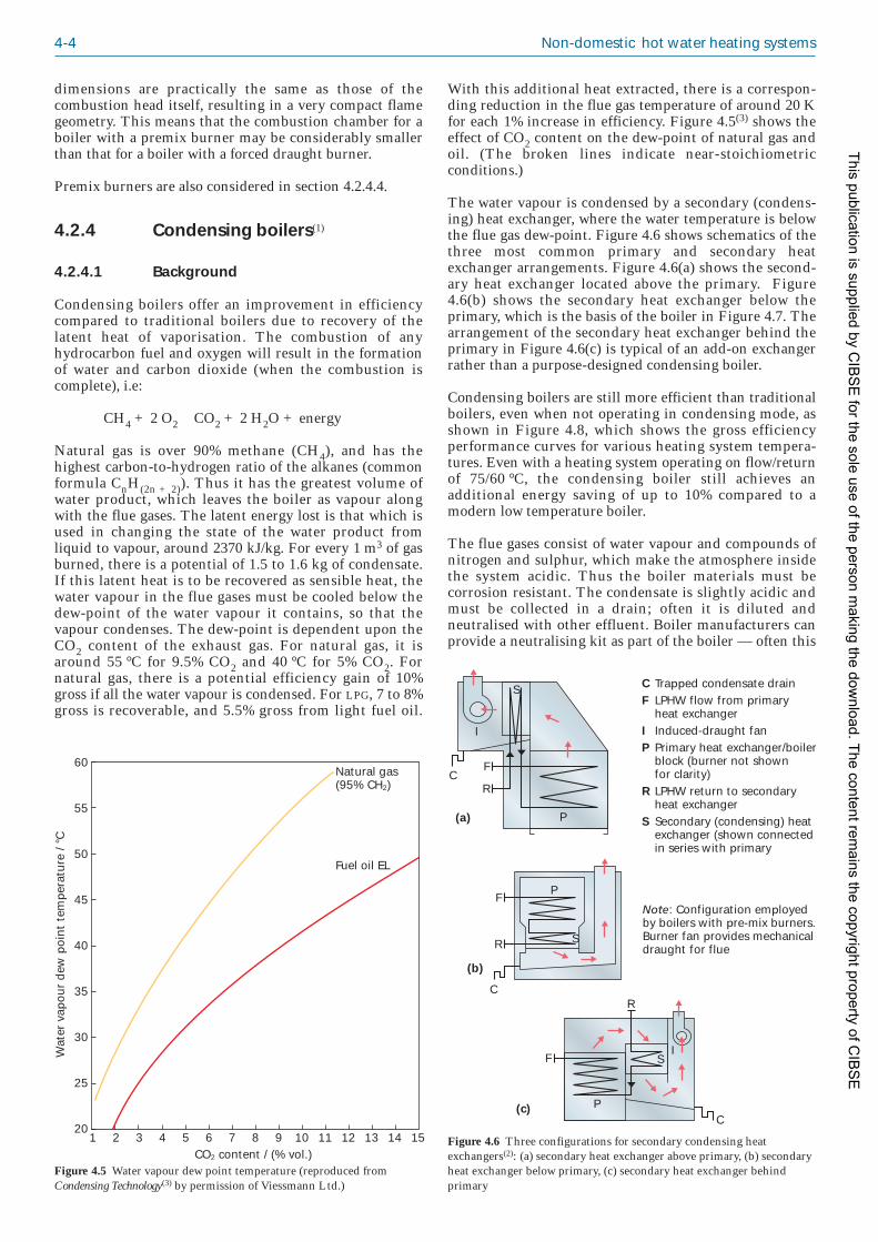
4-4 Non-domestic hot water heating systems
With this additional heat extracted, there is a correspon -ding reduction in the flue gas temperature of around 20 Kfor each 1% increase in efficiency. Figure 4.5(3) shows theeffect of CO2 content on the dew-point of natural gas andoil. (The broken lines indicate near-stoichiometricconditions.)
The water vapour is condensed by a secondary (condens -ing) heat exchanger, where the water temperature is belowthe flue gas dew-point. Figure 4.6 shows schematics of thethree most common primary and secondary heatexchanger arrangements. Figure 4.6(a) shows the second -ary heat exchanger located above the primary. Figure4.6(b) shows the secondary heat exchanger below theprimary, which is the basis of the boiler in Figure 4.7. Thearrangement of the secondary heat exchanger behind theprimary in Figure 4.6(c) is typical of an add-on exchangerrather than a purpose-designed condensing boiler.
Condensing boilers are still more efficient than traditionalboilers, even when not operating in condensing mode, asshown in Figure 4.8, which shows the gross efficiencyperformance curves for various heating system tempera -tures. Even with a heating system operating on flow/returnof 75/60 °C, the condensing boiler still achieves anadditional energy saving of up to 10% compared to amodern low temperature boiler.
The flue gases consist of water vapour and compounds ofnitrogen and sulphur, which make the atmosphere insidethe system acidic. Thus the boiler materials must becorrosion resistant. The condensate is slightly acidic andmust be collected in a drain; often it is diluted andneutralised with other effluent. Boiler manufacturers canprovide a neutralising kit as part of the boiler — often this
Wat
er v
apou
r d
ew p
oint
tem
per
atur
e / °
C
15CO2 content / (% vol.)
1 2 3 4 5 6 7 8 9 10 11 12 13 14
Natural gas(95% CH2)
Fuel oil EL
60
55
50
45
40
35
30
25
20
Figure 4.5 Water vapour dew point temperature (reproduced fromCondensing Technology(3) by permission of Viessmann Ltd.)
Trapped condensate drainLPHW flow from primaryheat exchangerInduced-draught fanPrimary heat exchanger/boilerblock (burner not shown for clarity)LPHW return to secondary heat exchangerSecondary (condensing) heatexchanger (shown connectedin series with primary
Note: Configuration employedby boilers with pre-mix burners.Burner fan provides mechanicaldraught for flue
F
F
F
R
R
R
P
P
P
S
S
S
I
I
C
C
C
CF
IP
R
S(a)
(b)
(c)
Figure 4.6 Three configurations for secondary condensing heatexchangers(2): (a) secondary heat exchanger above primary, (b) secondaryheat exchanger below primary, (c) secondary heat exchanger behindprimary
dimensions are practically the same as those of thecombustion head itself, resulting in a very compact flamegeometry. This means that the combustion chamber for aboiler with a premix burner may be considerably smallerthan that for a boiler with a forced draught burner.
Premix burners are also considered in section 4.2.4.4.
4.2.4 Condensing boilers(1)
4.2.4.1 Background
Condensing boilers offer an improvement in efficiencycompared to traditional boilers due to recovery of thelatent heat of vaporisation. The combustion of anyhydrocarbon fuel and oxygen will result in the formationof water and carbon dioxide (when the combustion iscomplete), i.e:
CH4 + 2 O2 → CO2 + 2 H2O + energy
Natural gas is over 90% methane (CH4), and has thehighest carbon-to-hydrogen ratio of the alkanes (commonformula CnH(2n + 2)). Thus it has the greatest volume ofwater product, which leaves the boiler as vapour alongwith the flue gases. The latent energy lost is that which isused in changing the state of the water product fromliquid to vapour, around 2370 kJ/kg. For every 1 m3 of gasburned, there is a potential of 1.5 to 1.6 kg of condensate.If this latent heat is to be recovered as sensible heat, thewater vapour in the flue gases must be cooled below thedew-point of the water vapour it contains, so that thevapour condenses. The dew-point is dependent upon theCO2 content of the exhaust gas. For natural gas, it isaround 55 °C for 9.5% CO2 and 40 °C for 5% CO2. Fornatural gas, there is a potential efficiency gain of 10%gross if all the water vapour is condensed. For LPG, 7 to 8%gross is recoverable, and 5.5% gross from light fuel oil.
This publication is supplied by CIB
SE
for the sole use of the person making the dow
nload. The content remains the copyright property of C
IBS
E

Major components of heating systems 4-5
applications that will achieve the greatest benefit fromcondensing boiler technology will be those with a heatingprofile that has a constant demand with few peaks, highannual heating requirements (e.g. with continuousoccupation, such as hospitals, hotels, sheltered accommo -dation, swimming pools) and high internal temperaturerequirements. The advantages of condensing boilers overnon-condensing will be reduced for applications where thebuilding requires heat at full load; this is likely to occurwhere the building has been designed for low heat losses,high incidental gains and short or intermittent occupancy.
Figure 4.9 shows a typical condensing boiler installationin a new development.
is specified by designers. Stainless steel or aluminiumalloys are suitable for the drain and also for the secondaryheat exchanger when gas is used, although the highersulphur content of oil may require different materials. Theuse of these alloys is expensive in both capital costs and interms of embedded energy (i.e. the energy used inmanufacture) and is another reason for using compact heatexchangers. Stainless steel should be used for the flue, seesection 4.5.
4.2.4.2 Applications for condensing boilers
Condensing boilers can be used in all LTHW heatingapplications, in new or existing systems and over a rangeof output sizes. Factors to consider are heating circuitdesign temperature, annual heat requirement, occupancytimes and design internal temperatures. In general, the
Air supplyFlue gas outlet
Sealed case
Venturi
Air supply fanPremix, fibre faced burner
Ignition and ionisation probe
Cast aluminiumsectional heatexchanger
Condensatedrain pan
Condensateconnection
Instrumentpanel
Flow, return andgas connections
Figure 4.7 Typical condensingboiler (secondary heat exchangerbelow primary) (courtesy of BroagLtd.)
Effi
cien
cy /
%
100
95
90
85
80
75
7080706040 50
Flow temperature / °C3020
Condensing boilerPressure jet fully modulatingGas atmospheric
Figure 4.8 Effect of return water temperature on boiler efficiency(courtesy of Ideal Stelrad)
Figure 4.9 Typical condensing boilers installation (courtesy of MHSBoilers Ltd.)
This publication is supplied by CIB
SE
for the sole use of the person making the dow
nload. The content remains the copyright property of C
IBS
E

4-6 Non-domestic hot water heating systems
The schematic arrangements shown in Figures 4.10 to4.12 suggest hydraulic circuits for two types of moderncondensing boilers which do not have separate secondary(condensing) heat exchangers, as do some older designs ofcondensing boilers as described earlier.
Figures 4.11 and 4.12 incorporate modular type condens -ing boilers. Characteristics of this type of boiler include:
— very low water content, and hence very smallstanding losses
— relatively large water-side pressure drop(50–100 kPa with a flow rate corresponding to an11 K temperature rise across the boiler
— typically have a stainless steel heat exchanger ofmulti-pass arrangement constructed from finnedtube
— provide rapid response to demand
— peak efficiency at low firing rate (in both condens -ing and non-condensing mode).
Because of these characteristics they should be installed ina primary circuit to ensure there is always adequate waterflow through a firing boiler. This can be achieved witheither a single primary pump to serve all boilers or eachboiler can be provided with a dedicated shunt pump.
Figure 4.10 shows the ‘traditional’ system design that islikely to be installed in existing buildings and is stillprovided for some new buildings. Here multiple boilersare used to serve all heat demands in a building with aprimary (constant volume) circuit and separate secondary
pumped circuits that may be a combination of constantand variable volume. The primary circuit often operates atconstant temperature (usually dictated by the domestichot water demand) to provide water at, say, 80 °C to thelow loss header. This is not ideal because the boilers willnot condense unless the return water temperature fromthe low loss header is below 55 °C and their maximumefficiency will not be achieved until the temperature fallsto approx imately 30 °C. Unless careful consideration isgiven to how the boilers are operated, they may neverachieve their condensing mode.
Typical approximate gross efficiencies of this type of boilerare given in Table 4.1.
It is worth noting from Table 4.1 that to maximiseefficiency the boilers need to operate at part load as long aspossible, and running the boilers at part load in non-condensing mode is only marginally less efficient thanwhen they operate at full load in condensing mode.
Figure 4.10 Low water content modular type condensing boilers serving constant and variable temperature circuits (courtesy of Hamworthy Heating Ltd.)
VT heatingload
DHWcylinder
VT heatingload
Roomsensor
Roomsensor
Flowsensor
Flowsensor
Outsidesensor
Pump
Pump
Pump
Mixingvalve
Optional individual shunt pumpscontrolled by each boiler
Primary circuit (constant flow)direct weather compensation Primary
pump
Low
loss
hea
derBoiler 1 Boiler 2 Boiler 3
Cascadeor unisoncontrol
Table 4.1 Approximate gross efficiencies for modular-type condensing boilers
Operating conditions Efficiency
Full load at 80/60 °C (non-condensing) 89%
Minimum load 80/60 °C (approx 20% full 90%load) (non-condensing)
Full load at 50/30 °C (condensing) 91%
Minimum load (approx 20% full load) 95%50/30 °C (condensing)
This publication is supplied by CIB
SE
for the sole use of the person making the dow
nload. The content remains the copyright property of C
IBS
E

Major components of heating systems 4-7
The following points should be considered in order tomaximise the efficiency of the boilers:
— Design the system to ensure the largest possibletemperature difference (most boiler manufacturersnow quote outputs with a ΔT of 20 K) and size theconstant temperature (CT) emitters for a water tem -peratures of 70/50 °C to ensure some condensing atmost times. This will also minimise pumpingenergy, but care needs to be taken with selection ofcontrol valves and commission ing/balancingvalves associated with the resultant low water flowrates; these are often oversized resulting in poorcontrol authority and inability to regulate duringcommissioning.
— When there is no demand from either the CTheating loads or domestic hot water, directlyweather-compensate the boiler flow temperature toincrease efficiency at part load.
— Reduce flow temperature to variable temperature(VT) loads further in response to room temperaturesensors (to account for high internal gains or highsolar gains).
— When there is significant demand for domestic hotwater sensed by a low temperature sensor in theDHW cylinder, start the DHW pump, override thedirect weather compensation and increase boilerflow temperature. (Standing losses in the DHW
AHU coilsand otherconvectiveheat emitters
Solarcollectorpanels
Destratificationpump
Direct fired gaswater heater(condensing)
Unventedstoragecalorifier
HWSflow
Flowsensor
Outsidesensor
Variable volume pump
Constant volume pump
Optional individual shunt pumpscontrolled by each boiler
Primary circuit (constant flow)direct weather compensation Primary
pump
Low
loss
hea
der
Und
erfl
oor
heat
ing
circ
uitsBoiler 1 Boiler 2 Boiler 3
Cascadeor unisoncontrol
Mains cold water
HWSreturn
Figure 4.11 Modular type condensing boilers serving variable temperature circuits with separate hot water generation employing solar panels (courtesyof Hamworthy Heating Ltd.)
This publication is supplied by CIB
SE
for the sole use of the person making the dow
nload. The content remains the copyright property of C
IBS
E

4-8 Non-domestic hot water heating systems
circuit or small demands could be offset by electrictrace heating or immersion heaters.)
— Operate the boilers under ‘unison control’, asdescribed below, rather than the traditionalapproach of ‘cascade control’.
— Under unison control, each boiler module isswitched on in turn at its lowest rate, and then allboiler modules are modulated simultaneously tohigher rates to match the system load. Thismethod of sequencing can offer higher operatingefficiencies, taking advantage of the higher partload efficiencies available at low firing rates.
— Under cascade control, a boiler modulates to itsmaximum rate before switching on the next boilerat that boiler’s lowest rate, hence maintaining thelowest number of boiler modules in operation for agiven heat load. This method of sequencing offershigher operating efficiencies for non-condensingboilers whose peak efficiency is at full output.
— Consider variable volume pumping on the CTcircuit (serving AHU coils etc.). This will avoid thehigh temperature return water that will result atpart load when a constant volume pumping circuitwith 3-port diverting control valves at emitters isused.
For new buildings, particularly where there will be arequirement to incorporate low or zero carbon technolo -gies (e.g. renewable energy sources) an improved solutionis shown in Figure 4.11. Here all circuits serving AHU coilsetc. are variable volume and any underfloor heatingcircuits are served by a separate constant volume pumpedcircuit with a small ΔT that may be constant temperatureor weather compensated via a 3-port mixing valve. In thisdesign the same type of boilers are used as those in Figure4.10, but they are directly weather compensated at alloperating times.
Here the domestic hot water (DHW) is generated by aseparate system. In this example, pre-heating of the DHW isby a solar thermal system and supplementary heatprovided by a direct gas fired, semi-storage water heater.The gas fired heater could be the condensing type tomaximise efficiency of the system when insufficient solarenergy is available. The DHW flow can be diverted to thecold fill connection on the unvented storage calorifier viathe 3-port diverting valve to pasteurise all of the storedwater on a timed basis.
Care is needed in selection of the coils in the air handlingunits (AHUs) and other convective heat emitters to ensurethey will operate effectively with the weather compensatedflow temperature and the correct weather compensationcurve needs to be applied to match the characteristics ofthe heat emitters.
Figure 4.12 High water capacity condensing boilers serving variable temperature and constant temperature circuits with separate high and lowtemperature returns
HWScalorifier
Airhandlingunits
Low temperaturereturn header
High temperaturereturn header
Flowheader
Boiler Boiler Boiler
Radiatorcircuits
Underfloorheating circuits
This publication is supplied by CIB
SE
for the sole use of the person making the dow
nload. The content remains the copyright property of C
IBS
E

Major components of heating systems 4-9
It may also be necessary to limit the flow temperaturefrom the boilers to no lower than that required by anyunderfloor heating circuits. (This will depend on thebuilding characteristics and where the underfloor heatingis installed in the building).
Figure 4.12 uses a boiler with a large water volume such asa reverse flame wet back furnace ‘shell-and-tube’ styleboiler (discussed in detail in section 4.2.6). However theconstruction is from stainless steel to permit condensing.Some characteristics of this type of boiler include:
— a very low water-side pressure drop (less than0.5 kPa with a flow rate corresponding to an 11 Ktemperature rise across the boiler) because thewater flows through the shell
— a large water content, which makes the boilertolerant of low or zero flow returning from thecircuits
— separate return water connections for high and lowtemperature water
— slightly higher efficiency in condensing mode thanwith water-in-tube boilers due to an increased areaof heat transfer with cool return water gaining heatfrom turbulent flue gases; however water-in-shellboilers are typically larger and heavier.
Because these boilers do not required a minimum constantflow they can be used without a primary constant volumecircuit. They can be used with variable temperaturecircuits or variable volume circuits.
In this example the boilers would not be directly weathercompensated but would operate to provide constanttemperature in the flow header.
Return water from constant temperature circuits fordomestic hot water generation or AHU coils (that would beclose to 80 °C at part load) and return water from weathercompensated variable temperature circuits with 3-portmixing valves for space heating (at 30–40 °C at low load)can be accommodated, with the return water from thespace heating circuits piped directly to the low tempera -ture return connections on the boilers. By doing this theboilers will condense for a significant proportion of theyear. The amount of condensing will depend on the designflow and return temperatures selected, which will haveimplications for the physical size (and therefore cost) ofthe emitters (i.e. a lower mean water temperature willresult in larger emitters).
Existing heating systems — replacing boilers
Incorporating condensing technology into an existingsystem may require some redesign of the system to ensurethat the efficiency is not impaired significantly.Traditionally, low temperature heating systems weredesigned to operate at 82/71 °C, having a mean watertemperature (MWT) of 76.5 °C; this is higher than desirablefor condensing boiler operation, which requires a returntemperature of 30–40 °C to function most efficiently. Oneway of operating condensing boilers efficiently in anexisting system is to design the heating system to meet theoptimum performance of the condensing boiler. This canbe achieved by selecting radiators that are sized for ahigher MWT than is actually required, since their larger
size means that more heat will be dissipated from themand so the return temperature will be lower. In many olderheating systems radiators were oversized and it may not benecessary to resize the existing heat emitters when instal -ling a condensing boiler.
In systems where the existing circuit requires fixed watertemperatures it may be possible to include a low orvariable temperature zone.
To further improve the performance of condensing boilersin existing heating systems, it is recommended to makeuse of external weather compensated controls to reducethe system temperature to suit the external weatherconditions in accordance with a preset characteristic.Figure 4.13 shows how weather compensation reduces theheating system flow temperature from point X, whichcorresponds to design conditions, to point Y, where noheating output is required. The emitter heat output pro -gressively decreases, causing the temperature differenceacross the heating circuit to decrease from the value at thedesign conditions to zero at point Y.
Condensing boilers are at their most efficient whenoperating in condensing mode, this starts to occur whenthe return temperature falls to 55 °C and increases as thetemperature falls further. On a weather compensated slopebased upon a 82/71 °C flow and return at –1 °C outsidetemperature, the flow and return temperatures will drop to65/55 °C when the outside air is 6 °C. In the UK theexternal temperature only falls below 6 °C for no morethan 10–15% of the entire heating season.
External weather compensation is available in two types,as follows:
— Indirect weather compensation: this is external to theboiler such as a building management system(BMS) or stand-alone compensated controller.These are normally installed to control thesecondary heating system using a 3-port mixingvalve to reduce the system flow temperature withthermostatic radiator valves (TRVs) on the heatemitters to account for local effects such as solarand internal gains.
Tem
per
atur
e / °
C
22External temperature / °C
–2 0 2 4 6 8 10 12 14 16 18 20
Flow to heating circuit
X
Return
Y
100
80
60
40
20
0
Figure 4.13 Weather compensation of flow temperature
This publication is supplied by CIB
SE
for the sole use of the person making the dow
nload. The content remains the copyright property of C
IBS
E

4-10 Non-domestic hot water heating systems
Where different emitter types are used, it is best toput them on different circuits with indirectweather compensation on each circuit withcompensation slopes that match the emitter types.
The circuit design needs to be considered toensure that the weather compensation controlproduces the lower return temperatures requiredto make the boiler condense. Particular care isneeded when the system also supplies domestichot water (DHW). Some condensing boilers areprovided with separate return connections for lowtemperature and higher temperature returns tomaximise the condensing mode. See Figure 4.14for examples.
— Direct weather compensation: when available, this isan integral part of the boiler controls. It has theability to modulate the boiler flow temperaturedirectly based on the external temperaturecondition.
It is particularly well suited to variable tempera -ture systems where the emitters all have the sameradiant to convective heat ratio, see Figure 4.14(b).This is because the outputs of radiators andconvectors do not vary by the same amount inresponse to a change in the flow temperature. TRVsshould also be used on the heat emitters to accountfor local effects such as solar and internal gains.
If it is used for systems with more than onetemperature zone, the boiler flow temperature willbe governed by the circuit that requires thehighest flow temperature, so this will be themaximum flow temperature available to any othercircuits. Often, these boilers will have DHWpriority, which will temporarily increase the flowtemperature in response to a hot water demand.Alternatively, where the load profile makes itsuitable the DHW circuit could be separated fromthe condensing boilers circuit and fed by a non-condensing boiler (Figure 4.14(c)).
Applications that optimise the performance of condensingboilers include floor heating systems (also known as‘underfloor heating’). Floor heating systems generallyrequire a constant system temperature with a flow oftypically 50 °C and a return of 40 °C, so the boiler willalways operate in condensing mode. Consideration mustbe given to the fact that in sizing a condensing boiler tooperate at these temperatures there may be a variety ofother circuits, such as radiant heating, and so anappropriate control strategy would need to be adopted tofacilitate this.
In all instances the planning of the heating system mustincorporate lower return water temperatures. As detailedabove this may be achieved by:
— changing the operational design temperaturecriteria
— utilising variable temperature circuits, throughweather compensated controls
— using lower temperature constant temperaturecircuits, as in the case of floor heating systems
— some combination of the above.
It is a current opinion that condensing boilers may not besuitable for all retro-fit applications, concerns being basedupon efficiency enhancement, flueing, collection ofcondensate and physical space limitations. Manufacturers
LTHW
HWS
To
Boiler Boiler
65 °C
10 °C
35 °C
35 °C
45 °C
Boiler
55 °CHT return
LT return
DPCV
To = Outside temperature sensor
indicates control circuit (either wired or wireless)
LTHW
HWS
Boiler Boiler Boiler
65 °C
10 °C
65/45 °C *
35 °C 35 °C
45 °C
DPCV
* 65 °C if HWS needed; 45 °C if LTHW only(b)
LTHW Boiler Boiler
45 °C
35 °C
35 °C
45 °C
DPCV
HWSstore
65 °C
10 °CN/Cboiler
82 °C
71 °C
(c)
(a)
To
To
DPCV = Differential pressure control valve
Figure 4.14 Condensing boilers and external weather compensation; (a) indirect, (b) direct, (c) direct with non-condensing boiler for HWS
(Note: temperatures are for the purposes of illustration only)
This publication is supplied by CIB
SE
for the sole use of the person making the dow
nload. The content remains the copyright property of C
IBS
E

Major components of heating systems 4-11
have developed products that will overcome many of theseconcerns, for example:
— The performance of many condensing boilers willat least match that of a non-condensing boilerwhen operating with return temperatures that donot allow the flue gases to condense. This allowsfor the heating circuit to be kept unchanged.When the emitters are finally replaced they canthen be re-sized to enable the boiler to condense,resulting in energy saving and reduced carbonemissions.
— There is also a wide range of flueing optionsavailable; these range from concentric andeccentric systems to conventional and flue dilutionsystems. Advice on the suitable flue systemmaterials and sizing/selection advice is readilyavailable from the manufacturers. See section 4.5for guidance on flueing for condensing and highefficiency modular boilers.
— Boilers have been developed specifically to fitdirectly into the space occupied by traditionalboilers. These products are also designed to takeinto account access and handling issues.
— Condensate lifting pumps and neutralisers arereadily available to assist in the removal andtreatment of condensate; these are particularlyuseful for installations below ground level.
Existing heating systems — combining boilers
Care must be taken when considering the combination ofcondensing and non-condensing boilers serving the samesystem to ensure that the return water temperature of thesystem is commensurate with the needs of the non-condensing appliances. Certain boiler types (typicallyforced draught appliances of the steel shell and many castiron sectional types) typically require that the minimumreturn water temperature is maintained above 60 °C toavoid the risk of corrosion due to condensation in the flueways of the appliance. Consideration must also be given tothe nominal water flow rates that are required individuallyby the boilers in the combination arrangement since, withcertain boiler types, wide flow/return temperature differ -ences may lead to excessive thermal stress and theconsequent possibility of failures.
System design and the control of the boilers should beoptimised to ensure the best possible efficiency from theinstalled arrangement. Typically the condensing appli -ance(s) should always be the lead heat generator(s) as theywill always return higher efficiencies than the non-condensing types. When planning to combine boiler typesin the same system, consider carefully the number ofboilers in the arrangement to ensure that the greatestbenefit is obtained from the condensing appliances.Examine the load profile of the attached system andexploit the benefits afforded by the high part-load efficien -cy of modulating condensing boilers. Environmentalheating systems operate at design load for only a verysmall percentage of the time that they are in operation andresearch suggests that heating systems working underlightest load conditions may be at only 15% of full designload. The operation of some building types (e.g. schools,offices and similar buildings working on a ‘9-to-5’schedule etc.) may seldom be required to operate at full
heating design conditions, as their working regime isgenerally during the mildest part of any given day. It maybe prudent therefore to try to select appliances to matchthe (lead) condensing boiler’s minimum output to thelikely low load output require ment from the system.
In older heating systems, there is likely to be a significantbuild-up of sludge and debris. Because the design of acondensing heat exchanger is more compact compared to,for example, a conventional cast iron heat exchanger, theyare less likely to be tolerant to these conditions.Precautions must therefore be taken to adequately cleanand flush the heating system before they are installed.Consideration should be given to interfacing the newboiler plant with the old system via a plate heat exchanger.This will not only act as a positive barrier againstcontamination of the new equipment by system dirt anddebris, but will also allow the new part of the system to besealed and pressurised while the existing part of thesystem remains open vented.
4.2.4.3 Atmospheric condensing boilers(1)
These are something of a hybrid that combines a conven -tional cast iron atmospheric boiler with a secondary(condensing) heat exchanger. Due to atmospheric burneroperation, this boiler design does not have a combustionair fan to pressurise the flue and provide assistance toevacuate the exhaust gas products, so this is provided byan exhaust gas fan within the boiler coupled to thesecondary heat exchanger.
These boilers take advantage of the robustness and largewaterways of a cast iron primary heat exchanger and lownoise levels in operation. They are often coupled withconventional, non-condensing atmospheric boilers in amodular arrangement, providing a cost-effective means ofcompliance with Building Regulations ApprovedDocument L2B(4) for a refurbishment project. However,the overall efficiency of these boilers is lower than acondensing boiler with a pre-mixed or forced draughtburner, and the burner control is only 1- or 2-stage, ratherthan modulating.
4.2.4.4 Premixed gas condensing boilers(1)
As explained in section 4.2.1, conventional atmosphericand forced draught burners do not mix the air and gasperfectly, the air being introduced both before (primaryair) and after (secondary air) the flame ports. Premixedburners thoroughly mix air and gas in sufficientproportions before the flame ports to produce (at leasttheoretically) complete combustion. Lower levels of excessair are therefore required and combustion conditionsmuch closer to stoichiometric (i.e. ideal) can be obtained.
Premixing is achieved in several ways, from simplyinjecting the gas into the eye of the fan to introducing itdownstream of the fan and utilising venturis, chambersand vanes to complete the mixing. The usual system,which also lends itself to modulation, is shown in Figure4.15. The variable speed fan is fitted with a venturiarrangement on its inlet that contains a gas dischargeannulus connected to a zero governor controlled gas valve.Provided that the gas supply pressure is constant, as thefan speed varies, the air and gas volumes also vary inproportion, hence ensuring that a precise air/gas mix is
This publication is supplied by CIB
SE
for the sole use of the person making the dow
nload. The content remains the copyright property of C
IBS
E

4-12 Non-domestic hot water heating systems
maintained throughout the modulation range of theburner.
As well as pulling in the combustion air, the fan must alsobe adequate to spread the fuel/air mix evenly along thelength of the burner head. The burner shown in Figure4.15 has a knitted matrix over the burner head to keep theflame stable. Alternatively, some manufac turers use astainless steel tube that has arrays of burner ports andflame retention ports, similar to an atmospheric burner.The flames sit around the entire burner head and theresult is an even temperature spread throughout thecombustion chamber. An alternative arrange ment is a flator slightly convex plaque burner, usually mounted at thetop of the boiler heat exchanger to give a down-firingconfiguration. This is sometimes called ‘flamelesscombustion’ because the flame appears as a radiant glowrather than as a defined flame. With a good, consistentfuel/air ratio and a minimum of excess air, typical grosscombustion efficiencies for premix burners are 85.5–87%.This is higher than most forced draught burners andmuch higher than atmospheric burners.
Premixed burners are suitable for cast iron, steel oraluminium heat exchangers. They are particularly suitablefor compact combustion chambers. Small combustionchambers often present matching problems for forceddraught burners. A narrow combustion chamber wouldrequire the flame shape to be thinner (and accordinglylonger) but this may present a problem for a shortcombustion chamber resulting in impingement of theflame on either the sides or rear of the boiler block. Theseconditions are ideal for a premixed burner. Conversely,premixed burners are normally limited by the length oftheir burner head, and consequently most outputs arelimited to around 300–400 kW. Higher outputs (1 MW)have been achieved by placing the mixing venturi after thefan, effectively using a conventional forced draught fan,controls and gas train. Although benefiting from thehigher combustion efficiency that is common to premixedburners, this arrangement loses the advantages of lowernoise levels and capital cost that come from fitting theventuri before the fan.
The wide range of modulation available to premixedburners (typically down to 20% for individual burners,although under controlled conditions some condensingboilers fitted with multiple premixed gas burners canmodulate to 2.5% of maximum rating) is often wasted onconventional cast iron or mild steel boilers. Modulatingbelow 50 or 60% of maximum output results in low flue
gas temperatures and the formation of acidic condensatein the boiler combustion chamber when the flue gastemperature drops below about 140 °C. Thus, premixedburners are particularly well suited to condensing boilers,where the full range of modulation can be utilised, flue gastemperatures are comparable to the boiler flow watertemperature and condensation in the combustion chamberis an advantage.
Noting that the dew-point of the water vapour isdependent upon the CO2 content of the flue gas (seeFigure 4.5), it is evident that increasing the excess air forcombustion will reduce the CO2 volume and consequentlyreduce the dew-point, and likely the latent heat recovered.A premixed burner is ideal for this situation, with itslimitation on excess air requirements.
Figure 4.16 shows an individual heat exchange coil from aheat exchanger. It is a flattened, 10 mm diameter stainlesssteel tube with a flue gas passageway of just 1 mmdiameter. Each coil will provide about 10 kW of heat. Thisis probably the most compact condensing boiler heatexchanger on the UK market, and the most widely used.As a wall mounted boiler, an individual unit can provideup to 180 kW heat output.
4.2.5 Modular boilers
The development of modular boilers began as early as the1960s, when changes in building methods produced theneed for boilers to become more responsive, compact andwith lower water content. They were suitable for replacinginstallations for low and medium capacity systems, whichtraditionally consisted of two large boilers that had beendeliberately oversized for the majority of the annualrequirement and hence formed an extremely inefficientand inflexible system.
There are two approaches to modular boiler instal lations.The first can be considered as a modular boiler systemmade up of several boilers arranged in modular format,piped in parallel and controlled by a remote boilersequence controller. Each boiler can be considered as astand-alone boiler that has its own water and gas supplyand own control panel. They are also fitted with draughtdiverters where appropriate, and individual flues thatconnect into a common header. The width has beenminimised so that each boiler can be coupled side-by-sideinto a compact system; manufac turers tend to limit thenumber to 6 or 8. It is common to use boilers of the samecapacity in the range of 40–120 kW output. A set of six oreight such units can provide a wide overall capacity range.The control of each boiler is usually on/off, althoughhigh/low/off operation is also available. The remote boiler
Air Gas
41234567
Gas valveAir intakeVenturiCombustion headIgnition/isolation electrodeBurner mounting flangeGas/air mixing chamber
6
3
2
57
1
Figure 4.15 Premixed gas burner for a cast iron boiler (courtesy of ClydeCombustions Ltd.)
Figure 4.16 Detail of heatexchange coil from a heatexchanger (courtesy of VeissmannLtd.)
This publication is supplied by CIB
SE
for the sole use of the person making the dow
nload. The content remains the copyright property of C
IBS
E

Major components of heating systems 4-13
allowance for initial heat-up capacity. The systemtherefore does not require the traditional 25–30%margin in standby capacity.
— Space saving and reduction in weight: shell andconventional sectional cast iron boilers are large,bulky units. It is often the case that the modularsystem, without the extra capacity but includingdraught diverters and flue header, is physicallysmaller. Modular boilers can also be more flexiblein layout so that spaces, unsuitable for largerboilers, can be utilised. Popular arrangements areL-shaped and back-to-back, and installations withas many as 20 modules are not uncommon.Lightweight, wall-hung modular boilers are alsoavailable that allow large outputs to be installed inrelatively small spaces.
— Ease of installation: the reduced weight of modularboilers compared to traditional larger units,coupled with the quiet operation of the atmos -pheric types, has led to other developments oftheir usage. These include:
(a) for new build, the support structure for theboilers can be reduced, leading to a lowercapital cost
(b) areas of buildings not previously suited asa boiler room could be utilised, particularlyrooftops and intermediate floors in high-rise blocks.
(c) the modules are highly manoeuvrable andcan pass through a standard doorway andfit into most lifts; therefore they can beused to replace worn-out traditional boilersthat had been originally built into theboiler room.
In many cases, the latter attributes allow the boilerinstallation to take place without the need to hire cranesand lifting gear. However, the pipework installation ismore complicated than that for a traditional two-boilerinstallation because of the need for all the modules to becoupled together on the water and gas sides, in addition tothe installation of the flue system. Manifolding up to eightmodules together is inevitably more complex.
Operating cost are reduced by means of the following:
— Reduction of thermal capacity: modular boilers arelighter in weight and have a lower water contentthan traditional boilers. As a result they have amuch lower thermal capacity and are able torespond more rapidly to changes in the system.This generally results in an overall improvementin thermal efficiency and lower running costs.
— Increased part load efficiency: when set up correctlywith the modules sequencing on and off, the loadmatching is more accurate than with thetraditional two-boiler system. The ideal control foran intermittent system would allow all modules toswitch on at the beginning of the heating periodand gradually to cut back as the load is satisfied,leaving a number of modules firing constantlywith one module intermittently turning on andoff. Each of the firing modules would be runningat full load and hence at maximum efficiency,producing an overall system efficiency higher thanthat of a traditional system.Figure 4.17 Example of a modular boiler (courtesy of BSRIA)
sequence controller determines the sequence in whicheach boiler operates.
The second approach incorporates several identicalindividual heat exchange modules, each with its ownpremix gas burner. Common headers for gas and waterform part of the modular boiler and provide independentwater flow/return and gas supplies to each heat exchanger.Prefabricated headers, pipework and modular flue headersare now supplied as integral components. The discharge ofthe combustion gases is into a common boiler casing.Copper finned tube heat exchangers offer more efficientheat transfer from the combustion gases to the water andsignificant weight reduction compared with cast ironboilers. Typical modular boilers will contain up to 6 or 12heat exchangers, each of 50–200 kW capacity. They can bestacked two or three modules high and any unusedpositions can be blanked off as required. Controls canagain be either on/off or, on some models, high/low/off.
An example of a modular boiler is shown in Figure 4.17.
Condensing modular boilers
The development of condensing versions of modularboilers allow them to be installed as part of a modularboiler system.
4.2.5.1 Advantages and disadvantages ofmodular boilers
The perceived advantages of the modular boiler system areboth reduced capital costs and reduced operating costs.
Capital costs are reduced due to the following:
— Reduction in standby capacity: the likelihood ofmore than one module being out of service at anyone time means that modular systems can be sizedon the calculated heat load plus, if necessary, an
This publication is supplied by CIB
SE
for the sole use of the person making the dow
nload. The content remains the copyright property of C
IBS
E

4-14 Non-domestic hot water heating systems
— Ease of servicing and maintenance: the need for allmodules to fire together to satisfy the load, otherthan when initially firing at the start of a heatingperiod, would usually be restricted to a few dayseach heating season. This allows maintenance tobe carried out on non-firing modules withoutinterrupting the heat supply.
Perceived disadvantages of the modular system are moreexacting system design and additional maintenance costs.With smaller waterways and lightweight construction,modular boilers tend to require more accurate water flowrates and better water quality which, if not maintained,can lead to early failure of the heat exchangers. Whilstmaintenance time may be equivalent between one largeboiler and several smaller ones, it should be rememberedthat each module has its own burner and associatedcontrols with a potential for more parts needing replace -ment.
4.2.5.2 Controls
To obtain the best performance from a modular system,the control set-up, such as the step control function andthe setting of the control and module thermostats(sensors), is a very important element. The modulethermostats must be set higher than the mixed flowcontrol sensor (this can contribute to reduced life as firinghotter) to enable the control sensor to turn the modules offin the correct sequence before they are extinguished bytheir own thermostats during periods of low demand. Thesequence or step controller ideally should have some formof time variation between steps to enable modules to bebrought on- or off-line more quickly or more slowly,depending on how close the mixed temperature is to theset point. Sequence controllers can also cycle all themodules on to ‘low fire’, before raising the first to ‘highfire’ when the part load efficiency is greater than the fullload efficiency.
The efficiency of a modular system can also be improvedby the addition of some form of outside temperaturecompensation that would reduce the number of firingmodules even further on warmer days.
4.2.5.3 Developments in modular boilertechnology
Recent advances in variable speed motors (and hencefans), microprocessor-based electronic burner controls,matched gas valves and burners capable of handlingsignificant turndown, have led to the current designs ofmodular boilers. Premix burners are now able to modulatesmoothly between 100% and, on average, 20% of full loadalthough lower figures are not unknown. The modularsystems can be supplied as a single unit, grouped togetheror stacked in condensing or non-condensing format withpipe kits and flue headers. Seasonal efficiencies aregenerally higher when compared with the earlier designs.
4.2.6 Shell-and-tube steel boilers
Shell boilers may be defined as those in which the steelshell contains the heat transfer surfaces. These aresurrounded by the water to be heated for hot water heatingsystems or, in the case of steam, by water up to a certainlevel above which is the space allowed for steam forma -tion.
A typical hot water boiler is shown in Figure 4.18 inwhich the combustion chamber is located centrally in theboiler in line with the burner. Heat from the burnerreverses at the blank end of the combustion chamber andexits at the front end into the burner door reversal space.The gases pass out into the final tube passes and exit at theboiler rear via a flue gas outlet box. This has a circularbranch for connecting to a chimney for safe dispersal ofthe hot gases.
A burner firing oil or natural gas can be used. With oilfiring heat is radiated to the combustion chamber surfacesby the emissive power of the molecules or incandescentparticles present in the flame/gases from the burner. Withgas firing there is a difference in flame emission leading tolower heat transfer than with oil firing. However, this isoffset by the higher convection in the tubes, which receivehotter gases into the tube passes.
Figure 4.18 Cutaway illustrationof a typical steel shell-and-tubeboiler (courtesy of Hoval Ltd.)
This publication is supplied by CIB
SE
for the sole use of the person making the dow
nload. The content remains the copyright property of C
IBS
E

Major components of heating systems 4-15
Branches are provided for connecting to the heatingsystem. At the front there is a flow connection thatincorporates both operating and limit thermostats tocontrol the burner firing. Depending on the burner type ahigh/low thermostat or modulating sensor may also beprovided. A level probe, to confirm water is present, maybe provided together with a thermometer to check thewater temperature. The safety valve, which is set at 70 kPa(0.7 bar gauge) above the working pressure, relieves excesspressure in the boiler. At the rear of the boiler the returnwater connection has an internal distribution system toensure that water is circulated to the lower areas of theboiler.
Access to the internal components, e.g. for tube cleaning,is provided by the hinged boiler door.
The boiler described above has a final pass of tubes weldedto the front tube plate and to the tube plate at the rear endto add to the two passes made in the reversal flow of thecombustion chamber.
Different combinations of tube layout are used in shellboilers involving the number of passes that the heat fromthe combustion chamber will make before beingdischarged. These include 2- and 3-pass configurationsand ‘dry’ or ‘wet’ backs (see below). For these boilers theburner is fixed to the end of the combustion chamber andaccess to the tubes is via doors that open to allow forcleaning and inspection purposes.
A ‘dry back’ boiler is one in which the hot gases from therear of the combustion chamber pass into a refractory-lined reversal chamber before passing through two passesof tubes to exit at the rear end of the boiler.
A ‘wet back’ boiler has a reversal chamber within thewater space of the boiler. This allows for greater heattransfer, thus improving the efficiency.
For all boilers the designer must prevent the boiler tubeplate material from reaching a critical temperature wherethe first pass of tubes is welded to the tube plate. For steelboilers the plate temperature should not approach 420 ºCin the area in which the tubes are positioned and high heattransfer is taking place.
Water treatment is essential to prevent scale formation onthe water side of the combustion chamber and tubes. Anyscale thus formed will restrict normal heat transferthrough the plate and lead to an increase in thetemperature of the plate. Excessive temperature in thematerial of the tube plate, tube ends or combustionchamber end can lead to cracking of the material andleakage from the boiler.
Typical thermal conditions inside the 3-pass wet backboiler are shown in Table 4.2.
Table 4.2 Typical heat transfer data for a three-pass, wet back, economicboiler (source: Hoval Ltd.)
Pass Area of Temperature Proportion of total tubes / m2 / °C heat transfer / %
1st 11 1600 56
2nd 43 850 30
3rd 46 410 14
The advantages of the shell-and-tube boiler include thefollowing:
— The entire plant may be purchased as a completepackage. The only tasks required prior tocommissioning the boiler are securing it to thefoundations and connecting it to water, electricity,fuel and steam supplies. Hence installation costsare minimal.
— Except where access is difficult, relocation of apackaged shell boiler from a boiler house atground level is straightforward.
— Modern shell boilers are well insulated andresidual heat losses are low.
— The construction, and hence maintenance, of steelboilers is generally straightforward, but should beundertaken by skilled personnel.
— Shell boilers often have one furnace tube andburner, and so control systems are generallysimple.
Although shell boilers may be designed and built tooperate up to 2.7 MPa (27 bar), the majority operate at1.7 MPa (17 bar) or less. This relatively low pressuremeans that the associated ancillary equipment should bereadily available.
Plant should be sized to meet the known maximumdemand which, for domestic use, will be provided by asingle boiler. For larger demands in large buildings,several boilers may be used so that the appropriatenumber of boilers are brought on-line to meet the varyingdemands. System water should not be allowed to passthrough off-line boilers.
4.2.7 Cast iron sectional boilers
The most familiar type of heating boiler for commercialapplications is the cast iron sectional boiler. Originallydesigned to burn coke, stoked by hand, it has beendeveloped for use with solid fuel, automatically fired, andfor oil or gas firing. Boilers up to 3 MW have beenproduced but few over 1.8 MW are currently available.
Generally, sectional boilers consist of individual sectionspulled together and held watertight by external steel tie-bars. The front and back sections differ from those in thecentre as they make provision for firing and cleaning atthe front and for a flue outlet at the back. Intermediatesections may be added for extensions or as replacementson failure.
A type of cast iron boiler has been developed for use withatmospheric gas burners. Sizes range from 20 kW to1 MW per boiler unit and heat-to-water efficiency (gross)may be around 80%. Some small modular boilers havesections built-up vertically. Figure 4.19 shows a typicalmodular, cast iron sectional boiler of this type with anatmospheric burner and a condensing heat exchanger.
Cast iron boilers are generally designed for operation withwater pressures of up to about 400 kPa (40 m head ofwater) are therefore suitable for most buildings excepthigh-rise developments. However, cast iron boilers areavailable that can operate with water pressures of up to
This publication is supplied by CIB
SE
for the sole use of the person making the dow
nload. The content remains the copyright property of C
IBS
E
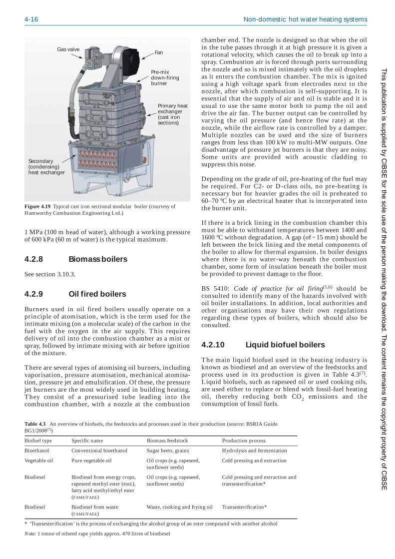
4-16 Non-domestic hot water heating systems
1 MPa (100 m head of water), although a working pressureof 600 kPa (60 m of water) is the typical maximum.
4.2.8 Biomass boilers
See section 3.10.3.
4.2.9 Oil fired boilers
Burners used in oil fired boilers usually operate on aprinciple of atomisation, which is the term used for theintimate mixing (on a molecular scale) of the carbon in thefuel with the oxygen in the air supply. This requiresdelivery of oil into the combustion chamber as a mist orspray, followed by intimate mixing with air before ignitionof the mixture.
There are several types of atomising oil burners, includingvaporisation, pressure atomisation, mechanical atomisa -tion, pressure jet and emulsification. Of these, the pressurejet burners are the most widely used in building heating.They consist of a pressurised tube leading into thecombustion chamber, with a nozzle at the combustion
chamber end. The nozzle is designed so that when the oilin the tube passes through it at high pressure it is given arotational velocity, which causes the oil to break up into aspray. Combustion air is forced through ports surroundingthe nozzle and so is mixed intimately with the oil dropletsas it enters the combustion chamber. The mix is ignitedusing a high voltage spark from electrodes next to thenozzle, after which combustion is self-supporting. It isessential that the supply of air and oil is stable and it isusual to use the same motor both to pump the oil anddrive the air fan. The burner output can be controlled byvarying the oil pressure (and hence flow rate) at thenozzle, while the airflow rate is controlled by a damper.Multiple nozzles can be used and the size of burnersranges from less than 100 kW to multi-MW outputs. Onedisadvantage of pressure jet burners is that they are noisy.Some units are provided with acoustic cladding tosuppress this noise.
Depending on the grade of oil, pre-heating of the fuel maybe required. For C2- or D-class oils, no pre-heating isnecessary but for heavier grades the oil is preheated to 60–70 °C by an electrical heater that is incorporated intothe burner unit.
If there is a brick lining in the combustion chamber thismust be able to withstand temperatures between 1400 and1600 °C without degradation. A gap (of ~15 mm) should beleft between the brick lining and the metal components ofthe boiler to allow for thermal expansion. In boiler designswhere there is no water-way beneath the combus tionchamber, some form of insulation beneath the boiler mustbe provided to prevent damage to the floor.
BS 5410: Code of practice for oil firing(5,6) should beconsulted to identify many of the hazards involved withoil boiler installations. In addition, local authorities andother organisations may have their own regulationsregarding these types of boilers, which should also beconsulted.
4.2.10 Liquid biofuel boilers
The main liquid biofuel used in the heating industry isknown as biodiesel and an overview of the feedstocks andprocess used in its production is given in Table 4.3(7).Liquid biofuels, such as rapeseed oil or used cooking oils,are used either to replace or blend with fossil-fuel heatingoil, thereby reducing both CO2 emissions and theconsumption of fossil fuels.
FanGas valve
Pre-mixdown-firingburner
Primary heatexchanger(cast iron sections)
Secondary(condensing)heat exchanger
Figure 4.19 Typical cast iron sectional modular boiler (courtesy ofHamworthy Combustion Engineering Ltd.)
Table 4.3 An overview of biofuels, the feedstocks and processes used in their production (source: BSRIA GuideBG1/2008(7))
Biofuel type Specific name Biomass feedstock Production process
Bioethanol Conventional bioethanol Sugar beets, grains Hydrolysis and fermentation
Vegetable oil Pure vegetable oil Oil crops (e.g. rapeseed, Cold pressing and extraction sunflower seeds)
Biodiesel Biodiesel from energy crops, Oil crops (e.g. rapeseed, Cold pressing and extraction and rapeseed methyl ester (RME), sunflower seeds) transesterification* fatty acid methyl/ethyl ester (FAME/FAEE)
Biodiesel Biodiesel from waste Waste, cooking and frying oil Transesterification* (FAME/FAEE)
* ‘Transesterification’ is the process of exchanging the alcohol group of an ester compound with another alcohol
Note: 1 tonne of oilseed rape yields approx. 470 litres of biodiesel
This publication is supplied by CIB
SE
for the sole use of the person making the dow
nload. The content remains the copyright property of C
IBS
E

Major components of heating systems 4-17
In the UK, liquid biofuel for heating applications ismainly produced by the re-processing of used vegetableoils (waste cooking oils that may be from a mixed supply)that are required to be cleaned and filtered, or from purevegetable oils such as rape seed. To produce biodiesel forheating boilers, these oils are chemically treated by aprocess known as ‘transesterification’. In Europe, liquidbiofuel is generally made only from rape seed oil that hasundergone transesterification to produce rapeseed methylester (RME) and then blended with heating gas oil.
Biofuel made from used or pure vegetable oils is describedas fatty acid methyl ester (FAME); both FAME and RME canbe used as biodiesels but they must conform to theEuropean biodiesel fuel standards BS EN 14214(8)
(primarily for automotive fuels) and BS EN 14213(9)
(primarily for heating fuels). Technically, both of thesefuels can be used for pressure jet oil heating applications.
Biofuel blends are designated ‘Bxx’, where ‘xx’ is thevolume percentage of extender that has been mixed withthe conventional base fuel, either kerosene or gas oil. Forexample, a blend containing 5% biofuel and 95% diesel istermed B5. The percentage blend is an important factorfor equipment manufacturers in order for them to approvetheir use without affecting warranties.
Both gas oil (‘35 sec oil’) and kerosene Class C2 (‘28 secoil’) can be used as the base mineral oil for the blending ofliquid biofuel but the user must be aware of the differencein ‘cloud point’ of the two types of oil. The cloud point isthe temperature at which cloudiness begins to appear,indicating that dissolved solids are no longer completelysoluble. As the temperature decreases further more ofthese solids will precipitate. This can cause blockages so itis important to consider the storage temperature, seesection 4.7.4. Kerosene has a much lower cloud point(approx. –40 °C) than gas oil (approx. –6 °C).
Although the cloud point for recycled cooking oils (FAME)is much higher than that for RME, they are still used. Onereason may be that FAME does not have any associatedenvironmental issues whereas concerns are being voicedover palm oil in particular. Biodiesel is an internationallytraded commodity and it may be difficult to know exactlywhere material originated but it is probable that, as themarket matures, issues of supply and feed-stock willbecome better controlled.
4.2.10.1 Basic guidelines for use of biofuel boilers
The following guidelines should be adhered to in the useof biofuels for heating applications:
— Liquid biofuels (e.g. FAME, RME) for heatingapplications must conform to BS EN 14213(9) orBS EN 14214(8).
— The ‘cold filter plugging point’ (CFPP), as definedin BS EN 590(10) and ‘cloud point’ are relevantwhen considering the low temperature effects onthe higher blends (i.e. B30 and above) of liquidbiofuels.
— Mineral oils must conform to BS 2869(11). At thetime of writing this allows for the inclusion of upto 5% of FAME in heating oil.
— Biofuels produced by blending bio-oils with eithergas oil or kerosene must be obtained only fromreputable suppliers who are able to demon stratecompliance with a certificated BSI/ISO qualitysystem and who are able to provide a full speci -fication for the fuel.
— Burner models (or retrofit kits) are likely to needspecial seals, flexible oil lines and filters suitablefor such fuels (conventional rubbers used for theseitems will be affected by biofuel use over time).
— Oil boilers, and in particular oil condensingboilers, may have components fabricated frommaterials that are unsuitable for use with liquidbiofuel (e.g. within the exhaust gas flue system)and so it would be prudent to consult the boilermanufacturer before using liquid biofuel.
— The use of liquid biofuels may require additionaland/or more frequent maintenance and cleaning ofthe burner, the appliance and the oil storage/distri -bution facilities.
4.2.10.2 Oil storage and delivery to the burner
The materials used in the construction of the oil tank andancillary equipment must be verified as suitable for usewith liquid biofuels by each manufacturer or supplier.
On existing oil tanks, particular attention should be givento the cleaning of the tank prior to biofuel use. As biofuelsare hydroscopic in nature, any water or contaminationwithin the tank will be taken-up by the biofuel. This willresult in blocked filters, pumps and oil nozzles therebynegating any warranty cover for such products.
The effects of long-term storage of biofuels and thepotential for bacterial growth is being evaluated by theindustry, but it would be prudent to consider the capacityof the oil storage (i.e. not oversized) and also the possibleuse of additives to limit bacterial growth.
High viscosity oils need to be heated in order to atomiseeffectively and pressure jet burners that use these fuelsoften have a pre-heater and/or a heated nozzle. This is thecase for pure untreated vegetable oils, i.e. rape, sunflowerand soya, which have high viscosities compared withstandard Class C or D mineral oils or blended trans -esterification biofuels. The following points need to beconsidered when selecting pre-heated burner models forthese oils:
— Identify the feed stock of the vegetable oil to beused.
— Check that trace heating will be provided for theoil storage and the oil delivery system (typicallymaintained at 10–15 °C).
— Check with the manufacturers that the oil storagetank and the ancillary equipment to be used instorage and delivery of pure vegetable oils aresuitable for this purpose.
— Contact the burner manufacturer to explain thatthis is the chosen fuel at the time of the order andto confirm that they will provide assistancethrough the product selection and commissioningprocesses.
This publication is supplied by CIB
SE
for the sole use of the person making the dow
nload. The content remains the copyright property of C
IBS
E

4-18 Non-domestic hot water heating systems
4.2.11 Boiler characteristics
Table 4.4 provides a summary of boiler characteristics.
4.2.12 Heat pumps
A heat pump takes up heat at one temperature and releasesit at a higher temperature. The energy required is usuallyobtained from a source of ambient heat such as theground, the outside air, or a lake or stream. Most heatpumps are based on an electrically driven vapour compres -sion cycle, whereby a cycle of evaporation and subsequentcondensation of the working fluid transfers heat from thesource to the building. A vapour compression cycle isshown in Figure 4.20.
The cycle is as follows:
(1) The working fluid evaporates by extracting heatfrom a low temperature source.
(2) The vapour is compressed mechani cally, whichraises its pressure and temperature causing it to
condense back into a liquid state thereby giving upits latent heat as useful heat.
(3) The liquid then expands through a valve causing adrop in pressure and partial vaporisation.
(4) The liquid/vapour mixture re-enters the evapo -rator for the cycle to be repeated.
Reversible air conditioners are sometimes referred to asheat pumps, but a purpose-built heat pump is optimisedfor heating.
Correctly designed and applied heat pumps use lessprimary energy than alternative direct fuel or electricheating methods and can offer carbon savings and reducedheating costs. Heat pump performance is expressed as acoefficient of performance (CoP), which is the ratio of heatemitted to electrical power input. A benchmark CoP of 3should be attainable for most space heating systems. Theyhave the advantage that there is no combustion orexplosive gases in the building.
The smaller the difference between the source tempera -ture and the output temperature the higher will be theCoP. Figure 4.21 illustrates the dependence of CoP ontemperature output.
This means that compression heat pumps are best suitedto providing space heating using low temperature heatingsystems such as underfloor heating, fan coils, low temper -ature radiators and air based systems. Using weathercompensation will also increase the efficiency by keepingthe heating system flow temperature as low as possible.Heat pumps can also be used to provide domestic waterheating but when doing this the efficiency will be reducedbecause of the higher temperature required. Also, auxiliaryheating may be required to provide pasteurisa tion forcontrol of Legionella bacteria.
For some hydronic heating systems it may be necessary toinclude a buffer tank to ensure that the load side system
Table 4.4 Summary of characteristics for different boiler types
Boiler type Nominal Typical gross Max. Fuels Flue arrangement Turndown Typical Typical NOx Economicoutput efficiency/ % working available ratio excess air emissions life / yearsrange / kW pressure in flue / (mg/kW·h)*
/ bar gases / %
Atmospheric 40–1000 80–83 4–6 Natural gas, Natural draught 1 to 1.4:1 30–40 267 20–25LPG
Forced draught 45–2000 82–84 (gas) 4–8 Natural gas, Conventional flue 1.6:1 12–23 119 (gas) 20–2584–86 (oil) class D oil 183 (oil)
to BS 2869,LPG
Atmospheric 50–350 84–87 (80/60 °C) 6 Natural gas, Natural draught — 25–47 211 15–20condensing 90–92 (50/30 °C) LPG
Premixed 28–180 (wall 85–89 (80/60 °C) 3–6 Natural gas, Room sealed or 5:1 (wall 20–28 44 10–15condensing mounted) 97–99 (50/30 °C) LPG conventional mounted)
60–1150 (floor flue 40:1 (floor standing) standing
Modular 50–200 (per 85–90 (80/60 °C) 3–10 Natural gas, Room sealed or 3:1; 4:1; 5:1 20–30 35–122 20condensing module) 90–93 (50/30 °C) LPG common header
Shell-and-tube 100–4000 82–84 (gas), 6 Natural gas, Conventional flue 2.5 to 3:1 20–25 112 (gas) 2085–87(oil) class D oil 155 (oil)
to BS 2869,LPG
* Based on net calorific value
Expansionvalve
Compressor
Superheatedvapour
Liquid
Dry saturatedvapourLiquid and
vapour
35 °C
Condenser
Heat out
Heat in
3 °C
Evaporator
Figure 4.20 Vapour compression cycle showing typical heat extractionand emission temperatures
This publication is supplied by CIB
SE
for the sole use of the person making the dow
nload. The content remains the copyright property of C
IBS
E

Major components of heating systems 4-19
volume is sufficient to prevent the heat pump from ‘shortcycling’.
Heat pumps with an output greater than 10 kWthermal arelikely to require a 3-phase electricity supply and in allcases the running and starting current requirements mustbe taken into account.
The minimum requirements for compliance of a heatpump system with Part L of the Building Regulations(12),for both new and existing buildings, can be found in theNon-Domestic Heating, Cooling and Ventilation ComplianceGuide(13).
Standards relevant to the design and use of heat pumpsystems include the following:
— BS EN 14511: 2007: Air conditioners, liquid chillingpackages and heat pumps with electrically drivencompressors for space heating and cooling(14) specifiesthe methods and conditions necessary for testingthe systems are fit for use over the designatedrange of operating conditions.
— BS EN 378: 2008: Refrigerating systems and heatpumps. Safety and environmental requirements(15)
covers the selection and appropriate handling ofthe refriger ant. It also covers selection of materialsthat are both compatible with the refrigerant andfunction at the required temperatures andpressures of the system.
— BS EN 1736: 2008: Refrigerating systems and heatpumps. Flexible pipe elements, vibration isolators,expansion joints and non-metallic tubes. Requirements,design and installation(16) describes the require -ments, design and installation of flexible pipes toeliminate excessive stresses within the pipe circuit.
— BS EN 15450: 2007: Heating systems in buildings.Design of heat pump heating systems(17) specifies thedesign criteria for electrically driven heat pumpsused alone or in combination with other heatgener ators. Aspects covered include the heat
pump, interfacing with the heat distributionsystem and control of the whole system.
— BS EN 15316-4-2: 2008: Heating systems inbuildings. Method for calculation of system energyrequirements and system efficiencies. Space heatinggeneration systems, heat pump systems(18) presentsmethods for calculating the additional energyrequirements of a heat generation sub-system inorder to meet the distribution sub-system demand.It standardises the required inputs, calculationmethods and resulting outputs.
— VDI 4640: Thermal use of the underground: Part 2:Ground source heat pump systems(19) is regarded as anindustry standard in the absence of an appropriateBritish Standard.
4.2.12.1 Ground source heat pumps
Advantages of ground source heat pumps are:
— high reliability (few moving parts and no exposureto weather)
— high security (no visible external components tobe damaged or vandalised)
— long life expectancy (typically 20–25 years for theheat pump and over 50 years for the ground coil)
— low noise
— low maintenance costs.
However, a disadvantage is the high capital cost of thecollector.
The term ‘ground source’ includes heat collection fromlake or river water. There are three types of groundcollection:
— Open-loop: ground water is extracted from aborehole at one temperature and returned via asecond borehole at a different temperature ordischarged to waste.
— Closed-loop, indirect: a closed loop of collector pipein which the circulating fluid is a secondary heatexchange fluid (water/antifreeze solution). This isthe most commonly used type.
— Closed-loop, direct: a closed loop of collector pipe inwhich the circulating fluid is the refrigerant.Although this removes one heat transfer barrierthey are less common because of the large amountof refrigerant and risk of leaks in connectingpipework.
With the first two methods the heat is transferred to theheat pump via a heat exchanger and the heat pump itselfusually consists of a factory assembled package requiringno refrigerant connections on site.
For closed-loop ground collectors heat transfer is drivenby the temperature difference between the ground and thecirculating fluid in the heat exchanger. At depths of lessthan 2 m, the ground temperature will show seasonalvariations above and below the annual average tempera -ture. The temperature variation decreases at lower depthsand below 10 m the temperature remains effectivelyconstant at approximately the annual mean air
Coe
ffic
ient
of
per
form
ance
/ C
oP
90
Output temperature / °C
0 10 20 30 40 50 60 70 80
12
10
8
6
4
2
0
Figure 4.21 Typical CoP against heat output temperature for heat inputtemperature of 0 °C
This publication is supplied by CIB
SE
for the sole use of the person making the dow
nload. The content remains the copyright property of C
IBS
E

4-20 Non-domestic hot water heating systems
temperature (8–14 °C).
The two main factors affecting heat transfer to a groundcollector are:
— the surface area of the collector (which depends onthe pipe length and diameter)
— the thermal properties of the ground (which willdetermine the length of heat exchanger needed tomeet a given load).
The ground collector may be installed horizontally orvertically. The geometry selected depends on the availableland, local soil type, excavation costs, and topographicalfeatures.
For horizontal installations the pipe is buried in trenches.The depth suggested by manufacturers is usually0·5–2·0 m. In order to minimise interference a minimumhorizontal separation of 0·6 m between pipes in the sametrench or 1 m between separate trenches is recommended.Spiralled, or coiled, pipework can also be used inhorizontal installations, with the extended coil either laidflat on the bottom of a wide trench or vertically in anarrow trench, see Figures 4.22(a) and 4.22(b)(7).
Vertical collector systems are used where available land islimited. The most common types of vertical borehole heatexchangers, known as single and double U-tubes, areshown in Figure 4.23(7).
The boreholes are generally 100 mm to 150 mm diameterand between 15 m and 180 m deep. With deeper holes,problems may occur with backfilling, static pressure and
insertion of the exchanger. (For a direct system themaximum depth of borehole is limited to ~30 m, in orderto ensure oil return to the compressor.) The spacingbetween adjacent boreholes should be sufficient to preventthermal interference; a separation of at least 5 m andpreferably up to 15 m is advisable. In general, a smallernumber of deeper holes will be most economical butconsideration needs to be given to the hydraulic design indetermining the final borehole layout, in order tominimise the parasitic pumping power.
In general, the higher the water content of the ground thehigher will be the thermal conductivity and this willimprove the heat transfer. However any flow of water willaffect the ability of the ground around the pipe to act as athermal store for systems providing heating and cooling.The hydrology of the area will determine whether water isable to flow between the boreholes on a seasonal orcontinuous basis.
For new buildings that require structural piling, ‘energypiles’ are sometimes installed instead of dedicatedborehole heat exchangers. The closed loop collector pipe isattached to the cage of the pile, which is then placed in thedrilled hole before the concrete is poured. The energy piletherefore performs a dual role of providing a structuralfoundation and a source of heat transfer. There is a costsaving over heat exchanger boreholes because drilling isnot required for the collector pipe. A good level of co-ordination is required with the structural engineer, whoneeds to be satisfied that the thermal effects do notendanger the structural integrity of the pile. The output ofthe pile will depend on the thermal properties of theconcrete used, as well as the bore size of the pile and thenumber of loops used.
For open-loop systems the ground water abstracted will beat approximately the ground temperature (8–14 °C). Theground collector system design depends on the hydro -geology and needs to be carried out by specialists andmust comply with the requirements of the EnvironmentAgency, which is responsible for the strategic managementof groundwater resources. An abstraction licence anddischarge permissions are required from the EnvironmentAgency and there will be charges for both abstraction anddisposal. The Environment Agency may insist that thewater is returned to the aquifer via an injection well ratherthan discharged to surface waters or the sewerage network.In this case the distance between the production andinjection wells must be sufficient that the temperature atthe abstraction well is unaffected by the returned water.
Geological reports for ground source heat pumps sites maybe obtained from the British Geological Survey (http://www.bgs.ac.uk). These provide site-specific data onthermal properties, geology and hydrogeology.
For further information on boreholes, see VDI 4640:Thermal use of the underground: Part 2: Ground source heatpump systems(19) and CIBSE TM45: Groundwater coolingsystems(20).
Applications for ground source heat pumps
Ground source heat pumps can be used in a wide range ofcommercial and public buildings, such as offices, schools,shops, hotels, sports centres and institutional buildings.
Figure 4.22 Coiled pipework for ground source heat pump; (a) horizontal, (b) vertical (courtesy of Kensa Engineering Ltd.)
(a) (b)
Figure 4.23 Schematic of typical vertical ground loop configurations; (a) single U-tube, (b) double U-tube
This publication is supplied by CIB
SE
for the sole use of the person making the dow
nload. The content remains the copyright property of C
IBS
E

Major components of heating systems 4-21
They can also be used with a wide range of systems,including the following:
— Central systems: where all heat pumps are located ina central plant room.
— Distributed systems: where a central water pump andsmall heat pumps serve individual rooms or zones.In large commercial buildings a water-loop heatpump is often used where the core of the buildingrequires cooling and the perimeter may requireheating or cooling. A ground source heat pumpcan replace both the boiler and the coolingequipment needed to maintain balance in the loop.
— Modular systems: where dedicated heat pumps andground loops serve individual zones.
— Hybrid or ‘bivalent’ systems: which consist of a heatpump and conventional heating equipment. Theground source heat pump is sized to provide thebase load and a second system operates either inplace of, or in addition to the heat pump to meetthe peak loads.
Application considerations
It is important that the proposed heat pump can satisfy theheating specifications over the full range of requiredoperating conditions. Care must be taken to consider theminimum ground loop temperatures when sizing closedloop ground source heat pumps. Appropriate sizing of theground coil is important to ensure the system works botheffectively and efficiently.
Oversizing the coil will result in a higher circulationtemperature in the ground coil and hence an improvedefficiency but this benefit might be negated by the higherenergy requirements of the circulating pump. It wouldalso mean unnecessarily high capital costs in systemswhere this is dominated by the cost of the groundcollector.
Undersizing the coil will mean that the heat pump will beunable to meet thermal comfort conditions without back-up heating. It also means that the circulation temperatureis lowered, which may lead to heat extraction becomingunsustainable.
Issues to consider when installing the coils include:
— checking that the ground where the collectors willbe positioned is free of drains and sewers
— checking for presence of mineworkings
— checking the suitability of the local soil andgeology for an effective collector performance andthat the collector can be sized correctly
— horizontal collectors are generally cheaper toinstall, whereas vertical collectors provide betterefficiencies due to the more stable temperature atgreater depths.
Figures 4.24, 4.25 and 4.26 show three arrange ments thatsuit different applications.
In the arrangement shown in Figure 4.24 only heating canbe provided if the heat pump is non-reversible. Areversible heat pump enables the system to providecooling when required. The arrangement is suitable forunderfloor heating, underfloor cooling, chilled beams andsimple fan coil/air handling systems in small installationssuch as shops and dwellings.
The system shown in Figure 4.25 can provide heating andcooling simultaneously and is therefore suitable forapplications where there may be a need for both heatingand cooling, such as an office and a neighbouring serverroom. The arrangement is suited to 4-pipe fan coil/chilledbeam applications and thermal storage systems with off-peak operation.
Figure 4.26 shows an alternative arrangement forproviding simultaneous heating and cooling in which thecontrols are simpler but two or more heat pumps arerequired. This arrangement is suited to 4-pipe fancoil/chilled beam systems and air handling systems.
Groundarray
Buffertank
Load
Heat pump(non-reversible
or reversiblerefrigeration)
Figure 4.24 Simple heating-only or heating/cooling system using a singleground source heat pump (courtesy of Earth Energy Ltd.)
Groundarray
Buffertank
Buffertank
Heat pump(non-reversible)
Figure 4.25 Simultaneous heatingand cooling using a single groundsource heat pump (courtesy ofEarth Energy Ltd.)
This publication is supplied by CIB
SE
for the sole use of the person making the dow
nload. The content remains the copyright property of C
IBS
E

4-22 Non-domestic hot water heating systems
4.2.12.2 Air source heat pumps
The advantages of air source heat pumps are:
— low capital cost with no drilling or trenching
— less disruption on site
— excellent performance at moderate air temperatures
— low maintenance costs.
However, there are disadvantages, as follows:
— more sensitive to outdoor temperature fluctuations
— noise emission from fan
— defrost required
— fan coil units are vulnerable to damage or debris.
Air source heat pumps work on the same principle asground source heat pumps but absorb energy from theoutside air, rather than from the ground. Ambient air isdrawn by a fan over the fins of a heat exchanger, whichforms the evaporator of the heat pump.
The air temperature will fluctuate more than the groundtemperature and both capacity and CoP are stronglydependent on outdoor temperature. The heat output fallsoff rapidly at low outdoor temperatures and sizing the unitfor the most severe condition can result in short cycling atmedium conditions. Air source heat pumps are usuallydesigned to operate with air temperatures down to –15 °Cbut the efficiency will be low at this temperature. Caremust be taken when sizing the heat pump to consider theminimum external operating temperatures. Some airsource heat pumps are fitted with a direct electric heater toboost the output at low outdoor temperatures (i.e.below –15 °C).
At outdoor temperatures below about 5 °C moisture fromthe air will condense to form ice on the outdoor heatexchanger, which will need to be defrosted. This is carriedout automatically but can reduce the heat pump efficiency.
Air source heat pumps are cheaper and easier to installthan ground source heat pumps as no ground collector isneeded.
Air source heat pumps can be mounted externally,internally with a ducted air supply, or as a split unit withthe evaporator and the compressor in an outdoor unitlinked by refrigeration pipework to an indoor unit
containing the condenser. Potential disturbance fromnoise, especially from the outdoor fan at night, may needto be considered.
The applications for air source heat pumps are similar tothose for ground source heat pumps.
4.2.13 Combined heat and power(CHP) units
See also section 3.10.2.
Combined heat and power (CHP), also known as co-generation, is the simultaneous generation of both usableheat and electrical power from the same source. CHPsystems can be used in applications where there is asignificant year-round demand for heating in addition tothe electricity generated.
A CHP unit consists of an engine (the prime mover) inwhich fuel is combusted and a generator that converts themechanical power produced by the engine to electricity.The ‘waste’ heat emitted from the engine is used toprovide space heating or domestic hot water and it is thisthat makes the CHP far more energy-efficient compared toconventional electricity power stations, where the heatgenerated by burning the fuel is wasted. CHP units canachieve efficiencies of around 80%. Also, the transmissionlosses associated with centralised generation and distri -bution via the national grid are eliminated.
CHP systems are classified according to their electricaloutput, see Table 3.1 in section 3.10.2.
A schematic of the main components of a CHP system isshown in Figure 4.27(7).
4.2.13.1 Types of prime mover
Various technologies can be used for the prime mover suchas reciprocating engines, steam turbines, gas turbines andcombined-cycle systems. A variety of fuels can also beused.
Reciprocating engines are commonly used for smaller CHPsystems (such as micro, mini and small scale CHP). Themajority of the reciprocating engines are automotive ormarine engines that have been adapted to run on naturalgas. These CHP systems produce two grades of waste heat:
Groundarray
Buffertank
Load
Load
Heat pump(non-reversible)
Buffertank
Cooling heat pump(non-reversible)
Low lossheader/tank Figure 4.26 Simultaneous heating
and cooling using two groundsource heat pumps (courtesy ofEarth Energy Ltd.)
This publication is supplied by CIB
SE
for the sole use of the person making the dow
nload. The content remains the copyright property of C
IBS
E

Major components of heating systems 4-23
high grade heat from the engine exhaust and low gradeheat from the engine’s cooling circuits.
Steam turbines tend to be used in medium and large scaleCHP applications. Systems include back-pressure steamturbine systems and pass-out condensing steam turbines.In both systems the steam is generated in a boiler beforeentering the turbine.
Gas turbines are used for large scale CHP systems. They areoften developments of aero-engines, the exhaust gasesbeing used to generate steam.
Combined-cycle systems consist of more than one primemover. These are normally gas turbines with the exhaustgases used to generate steam, which then passes through asteam turbine. These systems are known as combined-cycle gas turbine (CCGT) systems and are suited to thelarger installations.
4.2.13.2 Principal components
The principal components of a CHP systems are as follows:
— Prime mover: reciprocating engines and gasturbines run on natural gas while compressionunits run on diesel or fuel oil. Dual-fuel units arealso available which are suitable for natural gasand oil. Turbochargers can be used to boost theperformance of the unit. Gas turbines arecommonly used in larger CHP applications (1 MWeand above) and these also offer the advantage ofproviding higher temperature heat.
— Fuel system: usually natural gas or oil althoughbiogas and gases from landfill sites can also beused.
— Electrical generator: the generator converts themechanical power produced by the prime moverinto electrical power, which is fed into thebuilding’s electrical power distribution system.The generator usually runs at a fixed speed andmaintains its own frequency.
— Heat recovery system: CHP systems are provided witha heat recovery system that enables ‘waste’ heat tobe removed from the prime mover and supplied asa building heat load. The amount of heat that canbe usefully exploited within the building dictatesthe thermal efficiency of the CHP unit. The twomain sources of ‘waste’ heat are the exhaust gasesand the engine’s cooling water. A shell-and-tubeheat exchanger is typically used to recover heatfrom the exhaust gases of the prime mover, while aplate heat exchanger is used to recover heat fromthe engine’s water jacket.
— Cooling system: a cooling system is required toremove heat that cannot be used, such as thatproduced by CHP components (e.g. oil coolers orintercoolers). Heat will also need to be rejected insituations where the CHP unit is required togenerate electricity but not all of the recoveredheat can be used in the building. This can beachieved using a dry cooler and fan located outsidethe building.
— Air supply: an air supply and extract system isrequired to provide combustion air and remove theexhaust gases. For micro and small mini CHP unitscombustion air can be drawn from the surround -ings but for larger systems a dedicated air supplysystem may be required. Combustion air isextracted using a dedicated extract system, whichcan include additional components such as acatalytic converter to reduce pollutants (e.g. NOx),and silencers for noise attenuation.
— Control system: an automatic control system isusually provided to stop and start the CHP unitsafely and to modulate the heat and electricalpower output to meet the building’s load demands.The control system can also be used to monitor theoperating conditions and performance of the CHPunit.
— Enclosure: some form of enclosure may be required,depending on the location of the CHP unit (i.e.inside or outside) and the noise and vibration
Heating systemreturn water
Exhaust gasheatexchanger
Heat rejectionradiator(if required)
To boilercircuit
Engineexhaust
Enclosureventilation
Gas supplyControlsElectricity toswitchboard
Jacketwater heatexchanger
Lubricationoil heatexchanger
Hea
t ex
chan
ger
Figure 4.27 Schematic of themain components of a CHP system(reproduced from BSRIABG1/2008(7))
This publication is supplied by CIB
SE
for the sole use of the person making the dow
nload. The content remains the copyright property of C
IBS
E

4-24 Non-domestic hot water heating systems
specifications for the installation. Purpose-designed acoustic enclosures can be used tocontrol noise if necessary.
— Flue: unless a catalytic converter is installed theflue will need to be taller than that for gas firedboilers to ensure that there is no increase inground-level concentrations of NOx.
4.2.13.3 Tri-generation
Tri-generation involves the use of waste heat to generatechilled water via an absorption cycle, for comfort coolingand air conditioning applications. This allows the heatrecovered from the CHP prime mover to be used all yearround and so can greatly improve the usefulness and cost-effectiveness of a CHP unit.
4.2.13.4 Biomass CHP
Biomass can be used as a heat source for CHP systemsranging in output from several megawatts down to severalhundred kilowatts. The biomass fuel may be used either toproduce steam, which produces power via the steamturbine, or to produce combustible gases that can be usedto fuel prime movers including internal combustionengines.
4.2.13.5 Application of CHP in buildings
CHP systems in buildings can provide:
(a) Hot water: the hot water produced can be used fora range of applications including:
— domestic hot water for washing andcleaning purposes
— water heating for swimming and leisurepools
— space cooling using absorption cooling.
(b) Electricity: the electricity generated is used to meetpart of the total electricity demand of the building.It is possible to export any excess electricity to thenational grid during periods of low electricitydemand, providing that a regional electricitysupplier is willing to purchase the electricity.
(c) Heating: CHP units are rarely installed as theexclusive provider of hot water and electricity.Usually the CHP unit is sized to provide the baseheat load for the building and boilers are used tomeet the higher levels of thermal load.
Correct integration of the CHP unit with the boilers andwith the building’s electrical system are vital for achievingmaximum energy efficiency. Problems can arise when aCHP unit is run to satisfy a partial load because the returntemperatures will rise and cause the CHP unit to trip-outdue to overheating. This problem can be alleviated bydesignating the CHP system as the lead unit, so that itsupplies the heat load in preference to the boilers at alltimes. Such integrated systems provide security of supplyfor both electrical and thermal requirements.
CHP units are particularly suitable for applications thathave a year-round demand for the heat generated and aconsistent electrical base load. They should generally be
operated for a minimum of 4000–5000 hours per annum inorder to be cost-effective. The efficiency can be increasedif the exhaust gases are forced to condense, although caremust be taken in circuit design to ensure that low returntemperatures can be achieved from the system.
Some examples of CHP applications are shown in Table4.5(21).
For further information see BSRIA Guides BG 1/2008(7)
and BG 2/2007(22), CIBSE AM12(21), Carbon Trust GoodPractice Guides GPG043(23) and GPG256(24) and HVCATR/37(25).
Table 4.5 Examples of suitable applications for CHP (20)
Application Considerations
Swimming pools Continuous demand for pool heating and pumppower; high demand for domestic hot water
Leisure centres Operate from early morning to late evening;high demand for domestic hot water
Hospitals 24-hour operation; need high ambienttemperatures for patient care; high demand fordomestic hot water
Residential homes Elderly residents needing high ambienttemperatures; high demand for domestic hotwater
Hotels Long operating hours; need to maintaincustomer comfort; often include leisurefacilities; high demand for domestic hot water
University campus Office/teaching areas require heat during theday and for evening activities; accommodationareas require heat in early morning andevenings
Police stations 24-hour operation and occupancy; requirementfor standby generating capacity for criticaloperational facilities
4.3 Distribution network
4.3.1 Constant flow water systems
The majority of hydronic heating systems have tradition -ally been designed with fixed speed primary/secondarypumps to provide constant volume flow with the applica -tion of 3-port valves for controlling the heat loads in thesub-circuits. Arrangement of these valves in the sub-circuit can be such that the circuit is either a diverting,mixing or injection circuit, see section 5 of CIBSE GuideH(26). For these circuits, operation of the circulating pumpis always at constant speed irrespec tive of whether thesystem is operating at full load or part load.
4.3.2 Variable flow water systems
In variable flow hydronic systems, reducing pump speedor staging of pumps with boilers to suit part loadconditions is an energy efficient method of control.Variable flow systems were developed as an alternative toconstant volume systems because of the potential pumpenergy savings that can be derived by varying the flows tomatch the diversity of load requirements.
This publication is supplied by CIB
SE
for the sole use of the person making the dow
nload. The content remains the copyright property of C
IBS
E

Major components of heating systems 4-25
Figure 4.28(27) shows the variation in the return tempera -ture for variable flow and constant volume systems. Thecontrol arrangement for each load using 2-port and 3-portvalves are also shown on both types of systems, see Figure4.29(27). The designed flow and return water temperaturesare respectively 82 °C and 71 °C.
In the constant volume circuit controlled by a 3-portvalve, under part load conditions water at the flowtemperature is mixed with water from the load in thereturn. This has the effect of increasing the returntemperature at light load conditions. At zero demand,water at the flow temperature is returned from the circuit.
In a variable volume system with emitters that have asignificant radiant output, the partial closing of the 2-portvalve in order to reduce the heat emissions results in alower return water temperature. This reduction in watertemperature can be explained by the fact that the heatemitted from a radiator does not share a linear relation -ship with the flow rate, see Figure 4.30(28). As the flow ratereduces to, say, half of its original value the heat emitted tothe room only reduces to 80 or 90% of the original output.From equation 4.1, below, it is evident that if the flow ratereduces to 50% but the heat output only reduces to 90%then the temperature differential must increase to 90/50 =180% of its original value, i.e. a temperature difference of10 K increases to 18 K.
Φ = m· cp Δθ (4.1)
where Φ is the heat output from emitter (kJ), m· is themass flow rate of water through the emitter (kg·s–1), cp isthe specific heat capacity of water (= 4.18) (kJ/kg·K) andΔθ is the (water) temperature difference across the emitter(K).
As heating systems are likely to incorporate some form ofbypass arrangement, the return temperature is unlikely tobe as low as that suggested in Figure 4.28. The lowsecondary return water temperatures in variable volumesystems are therefore particularly useful when condensingboilers or CHP are used. In particular, the efficiency ofcondensing boilers increases with lower return watertemperature.
For more information see CIBSE Guide B(28) chapter 1,section 1.5.1.1 and Appendix 1.A1.2.
4.3.3 Pump selection
4.3.3.1 Constant flow applications
The following factors should be taken into account:
— The pump must be capable of delivering themaximum design water flow rate against thedesign pressure drop across the circuit that has thegreatest resistance (the ‘index’ circuit).
— The pump should operate within the stable regionof its output at full load. It should also be able toproduce 110–115 % of the total design flow againstthe index circuit resistance by change of impelleronly.
— To prevent excessive power consumption andwastage of energy, the pump’s impeller must betrimmed to the specified design flow rate andhead.
— To prevent excessive power consumption andwastage of energy, after commissioning, thepump’s impeller must be trimmed to the actualflow rate and head.
The pump motor must be rated to the absorbed kW of thepump at the duty point with safety margins as set down in
Tem
per
atur
e
Demand0% 100%
Flow temperature 82°C
Return temperature 71°C(constant flow) 3-port valve
Return temperature(variable volume) 2-portmodulating valve
Figure 4.28 Return temperature variations constant and variable volumeheating systems (reproduced from BSRIA AG16/2002(27))
1200 20 40 60 80 100
Relative flow / %
120
100
80
60
40
20
0
Rela
tive
hea
t ou
tput
/ % ( 1 – 2) = 10 Kθ θ
( 1 – 2) = 20 Kθ θ
Figure 4.30 Relationship between heat emission and flow rate for aradiator having n = 1.25 (see section 4.4) and θ1 = 75 °C, for designtemperature differences of 10 K and 20 K (source: CIBSE Guide B(28))
Constant flow(3-port valve)
Variable flow(2-port valve)
Load
Load
Figure 4.29 Schematic showing arrangement of valves in sub-circuit(reproduced from BSRIA AG16/2002(27))
This publication is supplied by CIB
SE
for the sole use of the person making the dow
nload. The content remains the copyright property of C
IBS
E
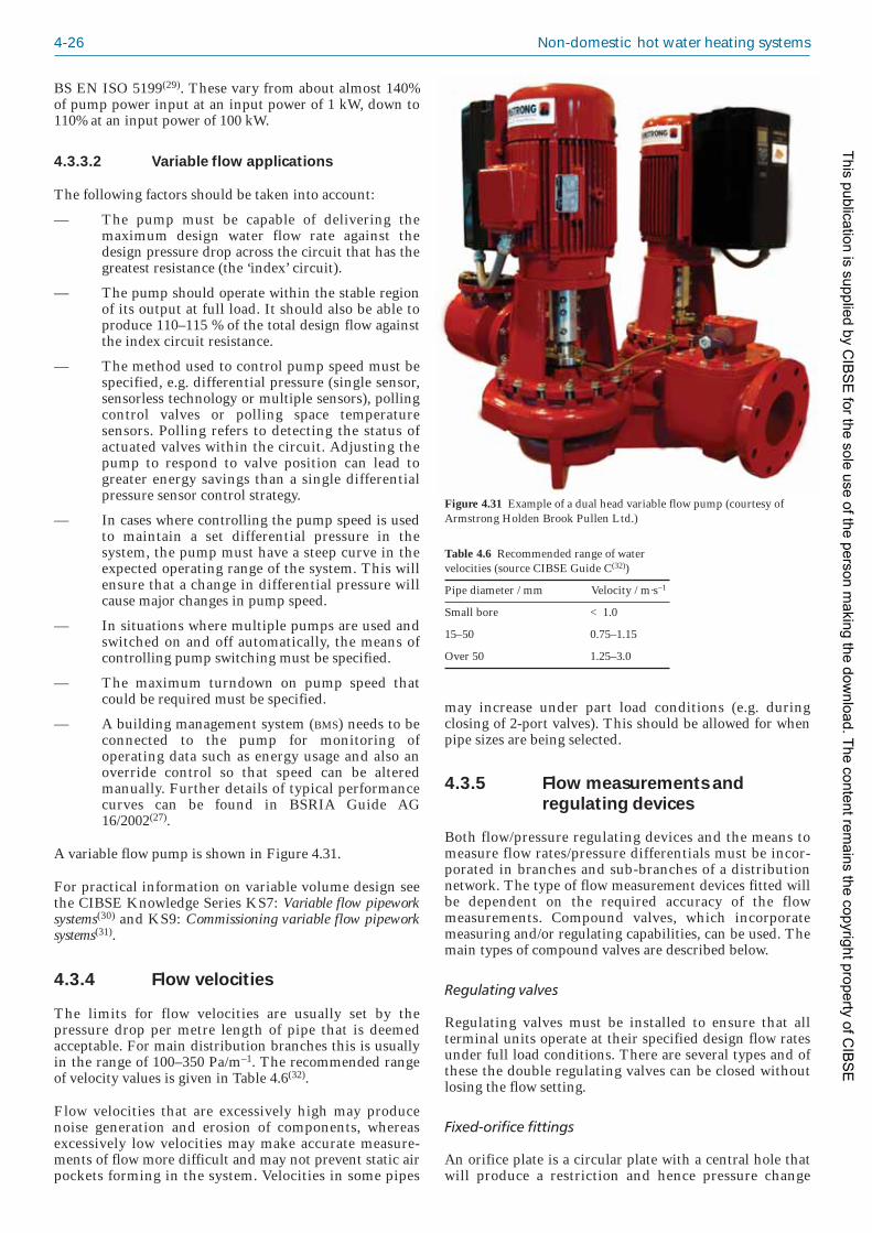
4-26 Non-domestic hot water heating systems
BS EN ISO 5199(29). These vary from about almost 140%of pump power input at an input power of 1 kW, down to110% at an input power of 100 kW.
4.3.3.2 Variable flow applications
The following factors should be taken into account:
— The pump must be capable of delivering themaximum design water flow rate against thedesign pressure drop across the circuit that has thegreatest resistance (the ‘index’ circuit).
— The pump should operate within the stable regionof its output at full load. It should also be able toproduce 110–115 % of the total design flow againstthe index circuit resistance.
— The method used to control pump speed must bespecified, e.g. differential pressure (single sensor,sensorless technology or multiple sensors), pollingcontrol valves or polling space temperaturesensors. Polling refers to detecting the status ofactuated valves within the circuit. Adjusting thepump to respond to valve position can lead togreater energy savings than a single differentialpressure sensor control strategy.
— In cases where controlling the pump speed is usedto maintain a set differential pressure in thesystem, the pump must have a steep curve in theexpected operating range of the system. This willensure that a change in differential pressure willcause major changes in pump speed.
— In situations where multiple pumps are used andswitched on and off automatically, the means ofcontrolling pump switching must be specified.
— The maximum turndown on pump speed thatcould be required must be specified.
— A building management system (BMS) needs to beconnected to the pump for monitoring ofoperating data such as energy usage and also anoverride control so that speed can be alteredmanually. Further details of typical performancecurves can be found in BSRIA Guide AG16/2002(27).
A variable flow pump is shown in Figure 4.31.
For practical information on variable volume design seethe CIBSE Knowledge Series KS7: Variable flow pipeworksystems(30) and KS9: Commissioning variable flow pipeworksystems(31).
4.3.4 Flow velocities
The limits for flow velocities are usually set by thepressure drop per metre length of pipe that is deemedacceptable. For main distribution branches this is usuallyin the range of 100–350 Pa/m–1. The recommended rangeof velocity values is given in Table 4.6(32).
Flow velocities that are excessively high may producenoise generation and erosion of components, whereasexcessively low velocities may make accurate measure -ments of flow more difficult and may not prevent static airpockets forming in the system. Velocities in some pipes
Figure 4.31 Example of a dual head variable flow pump (courtesy ofArmstrong Holden Brook Pullen Ltd.)
Table 4.6 Recommended range of watervelocities (source CIBSE Guide C(32))
Pipe diameter / mm Velocity / m·s–1
Small bore < 1.0
15–50 0.75–1.15
Over 50 1.25–3.0
may increase under part load conditions (e.g. duringclosing of 2-port valves). This should be allowed for whenpipe sizes are being selected.
4.3.5 Flow measurements andregulating devices
Both flow/pressure regulating devices and the means tomeasure flow rates/pressure differentials must be incor -porated in branches and sub-branches of a distributionnetwork. The type of flow measurement devices fitted willbe dependent on the required accuracy of the flowmeasurements. Compound valves, which incorporatemeasuring and/or regulating capabilities, can be used. Themain types of compound valves are described below.
Regulating valves
Regulating valves must be installed to ensure that allterminal units operate at their specified design flow ratesunder full load conditions. There are several types and ofthese the double regulating valves can be closed withoutlosing the flow setting.
Fixed-orifice fittings
An orifice plate is a circular plate with a central hole thatwill produce a restriction and hence pressure change
This publication is supplied by CIB
SE
for the sole use of the person making the dow
nload. The content remains the copyright property of C
IBS
E

Major components of heating systems 4-27
Pressure independent control valve (PICV)
Pressure independent control valves (sometimes referredto as ‘combination’ valves) integrate the functions of flowlimitation, modulating control and differential pressurecontrol within a single valve. This has potential parts andlabour cost savings and simplifies commissioning
For more information on flow measurement andregulating devices see CIBSE KS7(30).
4.3.6 Component selection guidelines
4.3.6.1 Regulating valves and flowmeasurement devices
The number of valves and devices should be limited tothose strictly necessary to balance and regulate the systemwithin the required tolerances.
Flow measurement devices should show a low pressureloss, to ensure that the system resistance is minimised.
Flow measurement devices must be sized using pressuredifferential/flow rate criteria and the minimum pressuredifferential signal should not be lower than 1 kPa.
across the plate when it is placed in the fluid flow. A fixed-orifice fitting is such a plate manufactured with thepressure tappings, which must be carefully positioned,already inserted.
Variable-orifice double regulating valve
This is a double regulating globe valve with a pressuretapping positioned on both sides of the valve seat, so thatthe pressure differential across the valve can be measured.The valve can also be used as an isolating valve or as afixed-orifice valve (when in the fully open position). Theflow rate is obtained by referring to the manufacturer’sflow rate or pressure differential charts.
Fixed-orifice double regulating valve
This is a double regulating valve that is incorporated intoa fixed-orifice fitting and enables flow measurement,regulation and isolation to be performed at a singlelocation. The flow rate is obtained by referring to flow rateor pressure differential charts.
Constant-flow controller
This controller regulates flow rates automatically,eliminating the need for manual adjustments and settings.As long as the pressure differential across it is within aspecified range it can be used to maintain constant flowconditions. Care must be taken when using this type ofcontroller in the same circuit as some other valves, such as2-port control valves and modulating 2-part control valves,since the valve operation can negate the performance ofthe controller.
Adjustable-flow controller
This controller also regulates flow rates automatically but,unlike the constant-flow controller, the flow rate can bechanged easily. Thus it is advisable to select this type ofcontroller if the required flow is not known when thesystem is being designed. For further details of how thesecontrollers work in practice, see BSRIA Guide AG16/2002(27).
Differential pressure control valve (DPCV)
This type of valve is used to maintain a constant pressuredifferential across a sub-branch in order to protect controlvalves downstream from excessive or varying pressures.This is achieved by the valve closing until a pre-setpressure differential is restored. Regulating valves are notnormally needed at the same location as the differentialpressure control valve, since the DPCV can be set tomaintain a specified pressure differential or flow rate. TheDPCV can be installed in either the flow or the return; forsystems with high temperature differentials the return ispreferable.
3-port control valve
3-port valves can be of two types; mixing types have oneoutlet and two inlet ports while diverting types have oneinlet and two outlet ports. The direction of flow through
32
41
+
Figure 4.32 Schematic of a 4-portvalve
each port must be specified if the valve is to workcorrectly.
2-port control valve
These valves consist have a single inlet and outlet port.
4-port control valve
4-port valves, see Figure 4.32, are used for control of flowto heating and cooling emitters such as fan coil units andchilled beams, where the design uses constant volumepumping. The valve operates in the same way as a 3-portmixing valve but the bypass is connected to a tee-piecethat forms part of the valve body. The valves are designedto give a resistance in the bypass similar to that across theemitter. They are used to simplify the piping arrangementat emitters and can be close coupled to emitters at themanufacturer’s works.
This publication is supplied by CIB
SE
for the sole use of the person making the dow
nload. The content remains the copyright property of C
IBS
E

4-28 Non-domestic hot water heating systems
Selection of double regulating valves should ensure thatthe required pressure reduction occurs at valve settings nolower than 25% open.
Flow measurement and regulation devices are onlyaccurate over a stated range of flow rates. At very low flowrates the tolerances become significant. For example, aflow rate of 0.01 l/s cannot be measured or controlled by adevice accurate to +–0.02 l/s. For this reason, very low flowrates should be avoided. Typically, the flow rates forindividual terminals should not fall below 0.01 l/s and,where a device regulates a group of terminals, theminimum flow rate should be 0.02–0.05 l/s.
4.3.6.2 Differential pressure control valves
DPCVs must be selected so that the pressure range that theyoperate within is compatible with the expected pressurevariations in the system.
For effective operation, the resistance of the DPCVs shouldmatch the resistance of the circuits they are controlling.
The set-point range must be selected so that the expectedtotal pressure drop of the relevant circuit will lie within it.
The flow coefficient (Kvs value) of the valve should becalculated to minimise the pressure reduction through it.
The size of the valve should be selected so that the portvelocity is limited to 3 m/s.
4.3.6.3 2-port control valves
Valve selection should be based on the maximum pressuredifferential in the circuit. Small diameter (15–20 mm) 2-port valves, used in conjunction with suitable actuators,can operate against differential pressures up to 16 bar, butlarger diameter valves may not be able to function at suchhigh pressures.
The entry velocity should also be limited to less than3 m/s.
For effective modulating, control valves need to haveequal percentage characteristics with an authority not lessthan 0.3. Note: the ratio of pressure drop across the valvewhen fully open to that across the complete circuit istermed the ‘valve authority’ (N) and is expressed as:
N = P1 / (P1 + P2) (4.2)
where N is the valve authority, P1 is the pressure dropacross fully open valve and P2 is the pressure drop acrossremainder of the circuit, see Figure 4.33. Refer to CIBSEKS7(30) for further guidance on valve authority.
4.3.7 Provision for thermal expansionof pipework
4.3.7.1 Introduction
This important part of the distribution system design isoften overlooked by the designer and responsibility issometimes transferred to the installation contractor in the
Figure 4.33 Calculation of valve authority: pressure drop across (a) 3- or4-port valves and (b) 2-port valves
p1 + p2
p1
p1 + p2
(b)(a)
p1
specification. This is because the installation contractor isgenerally responsible for producing installation drawingsthat include all the information necessary for on-siteinstallation of the works, including the detail design ofpipe supports and provision for thermal expansion.
What designers sometimes overlook is that it must befeasible to install the services within the general routesindicated on the design drawings without the need for re-routing of the services and/or the addition of expansionjoints or flexible connections that would incur additionalcosts.
In addition, the incorporation of expansion devices(particularly on large pipework or where axial expansionjoints are employed) could result in large loads beingimposed on the building structure at the anchor pointsthat could require modifications to the structural design.
To minimise the above risks the following check listshould be considered by the designer:
— Review the design in terms of pipework expansionand, whenever possible, endeavor to account formovement due to thermal expansion andcontraction by natural changes in the direction ofpipework, incorporating anchor points and guidescorrectly.
— Consider the impact of the choice of pipe material.For example, PVC-C pipe will expand 6–7 timesmore than steel pipe, and PE-X approxi mately 15times more than steel. (For plastic pipeworksystems it is critical to design in accordance withthe particular system manufac turer’s installationinstructions.
— Assess the maximum pipework expansion on longhorizontal runs, and in risers.
— Check that the length of offsets for final run-outsof pipework to heat emitters are adequate and, ifrequired, include flexible connections.
— Describe the design philosophy for thermalexpansion either on the drawings or in thespecification. For example, if it is established thatexpansion bellows are not required then thereshould be some notes to explain the reason for thisdecision (e.g. flexible connections may be includedat heat emitters, combined with utilisation of thenatural flexibility of the pipework material).
This publication is supplied by CIB
SE
for the sole use of the person making the dow
nload. The content remains the copyright property of C
IBS
E

Major components of heating systems 4-29
— Add a note to all design drawings stating that anyprovisions for expansion, anchors and guides areshown for guidance/costing purposes and that theactual detailed requirements shall be determinedby the contractor as part of the installationdrawings.
— When expansion bellows are incorporated,calculate the anchor loads and ensure adequateprovision is made in the design of the buildingstructure.
— Consider angular (hinged) expansion joints inpreference to axial type, to minimise anchor loads(see section 4.3.7.3).
4.3.7.2 Thermal expansion
The change in length of pipework, for both expansion andcontraction, due to temperature variation can becalculated using:
Δ l = l α Δθ × 1000 (4.3)
where Δ l is the change in length of the pipe (mm) due totemperature change Δθ , l is the original length of the pipe(m), α is the coefficient of linear expansion (K–1) and Δθis the change in temperature to which the pipe is subjected(K).
Table 4.7 gives typical coefficients of linear expansion,their expansion rate relative to steel, and expansion inmm/m of pipe, for the materials commonly used in lowtemperature hot water heating systems with a maximumdesign temperature of 80 °C. (Note: it is advisable to obtainactual figures at design operating temperatures from themanufacturers, particularly for plastic systems.)
Whilst the coefficients of linear expansion for steel andcopper are low in comparison with those of other metals
and only a tenth of those for pipeline plastics, this doesnot mean that their effects may be ignored
4.3.7.3 Methods of accommodating thermal expansion
In all instances, short rigid connections between thevarious system components, boilers, pumps etc., andbetween distribution mains and heat emitters, should beavoided.
An example is the connection of final run-outs to heatemitters from a long horizontal main. The heat emitterwill act as a natural anchor point and adequate naturalflexibility needs to be incorporated into the pipework toavoid imposing stress on the pipe connection. Theexample shown in Figure 4.34(33) could be the end termi -nal on a long horizontal main running in a floor void. Thefigure gives equations that may be used to calculate theoffset required to accommodate the thermal expansion ofthe pipework. If this cannot be achieved in practice,additional bends in the pipework or flexible hoseconnections at the heat emitters will be required.
In making calculations for dealing with the results ofthermal expansion, it is usual to take account of what iscalled ‘cold draw’ or ‘cold pull’. In effect, this representsaction taken during installation whereby the loop or offsetis shortened to take up a proportion (often half) of theanticipated expansion in service. By this expedient, theforce on the anchor points is reduced pro-rata.
Note: if 50% cold pull is applied, the offset will absorbtwice the expansion, however this is difficult to monitoron site and it actually increases the anchor forces due tothe increased rigidity of shorter offset pipes.
Allowance for pipework expansion may be provided for ina number of ways:
— by length and changes in direction: the example inFigure 4.35 shows points designated as anchors orguides to ensure full control of the expansion; thisis known as natural flexibility
— by purpose made axial or angular expansion joints:see Figures 4.36 and 4.37.
The important difference between the two types ofexpansion joints illustrated in Figures 4.36 and 4.37 is thatangular joints are pressure-restrained and do not imposelarge forces on the pipework. Therefore ‘light’ anchorsonly are required to direct the movement of the pipe inthe desired direction, and the predominant force in anangular joint is friction. Anchors for axial joints arerequired to restrain the force due to internal pressure plus
Table 4.7 Coefficients of linear expansion and comparative expansionrates of common types of heating pipework
Material Coefficient Expansion Expansion of linear rate relative from 0 °C expansion, to steel to 80 °Cα / K–1 / (mm/m)
Steel 11.3 × 10⁻⁶ 1 0.9
Copper 16.9 × 10⁻⁶ 1.5 1.4
PVC-C 70 × 10–6 6 5.6
PE-X 170 × 10–6 15 13.6
PB 130 × 10–6 11.5 10.4
Multi-layer (e.g. 25 × 10–6 2.2 2PE-X/aluminium/PE-X
Anchor
Anchor
ExpansionLength of pipe
Cold pull
Length of offset (Io):Io = 0·1 d x for steel pipe Io = 0·06 d x for copper pipewhere d is the pipe nominal diameter (mm)and x is the expansion (mm)
IoFigure 4.34 Flexibility of a pipewith an offset (reproduced fromthe Minikin Design Book(33) bypermission of Minikin and SonsLtd.)
This publication is supplied by CIB
SE
for the sole use of the person making the dow
nload. The content remains the copyright property of C
IBS
E

4-30 Non-domestic hot water heating systems
the force to compress the joint plus the force to overcomefriction due to pipe movement.
4.3.7.4 Sources of further guidance
The best sources of guidance on the design of pipeworksystems to account for thermal expansion are themanufacturers of expansion joints and specialist pipeworksystems. The Chartered Institute of Plumbing andHeating Engineering’s Plumbing Engineering ServicesDesign Guide(34) deals with pipework expansion andincludes guidance on calculating forces on anchors andprovides examples of guides and anchors. See also MinikinDesign Book: The Application of Expansion Joints toPipework Systems(33) for detailed guidance on the flexibilityof pipework systems and the application of expansionjoints.
4.3.8 System expansion,pressurisation and automaticreplacement of water losses
4.3.8.1 Introduction
The density of water reduces significantly as temperaturerises. For example if water is heated from 4 °C to 80 °C thedensity falls from 1000 kg/m3 to 971.8 kg/m3, which isequivalent to an increase in specific volume from0.001 m3/kg to 0.001029 m3/kg. This corresponds to anincrease in the system volume of 2.9%, and is sometimesexpressed as a ‘water expansion factor’ (i.e. 0.029).
Table 4.8 gives values for the percentage expansion ofwater when heated from 4 °C up to 200 °C. Appendix 4.A1of CIBSE Guide C(32) includes a table of water density at arange of temperatures.
All low temperature hot water (LTHW) heating systemsmust have facilities for the following:
— maintaining pressure at each point of the systemwithin acceptable limits, to ensure safe operationof the system but also ensuring a minimumpressure is maintained to avoid low pressurecavitation, and evaporation
— compensation of volume variations of the systemwater due to temperature variations
— correcting water losses caused by the system bymeans of a hydraulic back pressure.
4.3.8.2 Open systems
The simplest way of accommodating the above require -ments is by the use of a feed and expansion tank located
Guide Anchor
Anchor Guide
Figure 4.35 Natural flexibility ofmains pipework
Intermediateguide
Intermediateguide
Anchor AnchorPrimaryguides
Axial expansion joint
4 d 4 d
14 d 14 d
Primaryguides
Figure 4.36 Axial (orunrestrained) expansion joints(reproduced from the MinikinDesign Book(33) by permission ofMinikin and Sons Ltd.)
Guide Anchor
Anchor GuideGuide
Cold pull
GuideAllow about 40 pipe diameters
Figure 4.37 Angular, hinged (orrestrained) expansion joints(reproduced from the MinikinDesign Book(33) by permission ofMinikin and Sons Ltd.)
Table 4.8 Percentage expansion of water heating up from 4 °C
Temperature / °C Expansion / % Expansion factor
40 0.79 0.0079 50 1.21 0.0121 60 1.71 0.0171 70 2.27 0.0227 80 2.90 0.0290
90 3.63 0.0363100 4.34 0.0434110 5.20 0.0520 120 6.00 0.060130 7.00 0.070
140 8.00 0.080150 9.10 0.091160 10.2 0.102170 11.4 0.114180 12.8 0.128
190 14.2 0.142200 15.7 0.157
This publication is supplied by CIB
SE
for the sole use of the person making the dow
nload. The content remains the copyright property of C
IBS
E

Major components of heating systems 4-31
above the highest point in the system. These systems are‘open’ systems, i.e. vented to atmosphere, and must havean open safety vent pipe to provide an unrestricted pathfor the relief of pressure (or steam) if the boiler tempera -ture controls should fail. The point at which the feed andexpansion pipe is connected to a piping system is the onlyposition at which any external pressure is applied and isknown as the neutral point of the system. This neutralpoint should be at the position where the expansion ofwater will be at the lower of the two temperatures, i.e. thereturn, and the connection should also be on the suctionside of the circulation pump to reduce the risk of lowsystem pressure which could both draw air into the systemand create a risk of cavitation in the pump.
Figure 4.38(a) shows the preferred arrangement for feedand expansion piping and (b) to (d) show configurationsthat should be avoided. In the preferred solution the pumpis in the flow and the vent and the feed and expansionpipe are in balance and, since virtually the whole system isunder pump pressure, air release will present no problems.
These systems are generally only found on smaller, oldercommercial buildings.
4.3.8.3 Sealed systems
The majority of new low temperature hot water systemsare static ‘sealed’ systems, pressurised by a packaged unitcomprising an expansion vessel(s) complete with internaldiaphragm charged with inert gas or air plus a watermake-up unit comprising a break tank and pump(s).
It should be noted that not all pressurisation units includea break tank. To avoid stagnation of water and possiblecontamination, some systems are designed to supply waterdirect from the mains water supply through an approvedbackflow prevention device that must comply with theWater Supply (Water fittings) Regulations 1999(36). This is
usually a reduced pressure zone (RPZ) valve but the actualrequirements would be dictated by the category of risk.
Figure 4.39 shows the relative position of the diaphragm,(a) before connection, (b) connected to a filled system(cold fill), (c) during heating, (d) at system workingtemperature. The vessels are sized with what is known asan ‘acceptance factor’, see Table 4.9.
Sealed systems must incorporate a safety/pressure reliefvalve, either fitted to the boiler or installed in the outletpipework from the boiler. BS 7074: Part 2(37) provides acode of practice for the application and installation ofexpansion vessels and ancillary equipment, gives amethodology for the selection and installation of theequipment, establishing system pressures, and safety valvesizing.
Table 4.9 is a summary of an example given in AppendixA1 of BS 7074: Part 2, and shows the recommendedprocedure for calculating the size of an expansion vessel. Itis usual for the manufacturer of the pressurisation unit tocalculate the size of the expansion vessel using the designinformation printed in bold italic type.
(c) Avoid(a) Preferred arrangement
(d) Dangerous – avoid(b) Avoid
Open vent
Boiler
Figure 4.38 Alternativearrangements for feed andexpansion piping (reproducedfrom Faber and Kell’s Heating andAir Air-conditioning of Buildings(35)
by permission of AECOM)
(a) (b) (c) (d)
Systemconnection
Diaphragm
Charging connection
Figure 4.39 Expansion vessel diaphragm positions (reproduced fromFaber and Kell’s Heating and Air-conditioning of Buildings(35) by permissionof AECOM)
This publication is supplied by CIB
SE
for the sole use of the person making the dow
nload. The content remains the copyright property of C
IBS
E

4-32 Non-domestic hot water heating systems
From the calculation shown in the table, the manufactureris likely to select a vessel of 1300 litres and this wouldresult in a revised acceptance factor of 0.236 and a revisedfinal working pressure of 3.33 bar gauge.
The safety valve set pressure would then be (3.33 + 0.5) =3.83 bar gauge.
The arrangement shown in Figure 4.40 is a developmentof an arrangement shown in BS 7074: Part 2(37) indicatingthe relative locations of pump, boiler and expansion vesselconnection point. This shows the following ancillaryfeatures:
— temporary quick-fill connection
— automatic make-up unit, including facilities forbackflow prevention in accordance with the WaterSupply (Water Fittings) Regulations 1999(36),category 5
— pressure controls including:
(a) pressure switch to maintain cold fill pres -sure by running the pump when required
(b) high and low pressure cut-out switchesthat shut down the boiler on sensingpressure outside the normal operatingparameters
(these may not be part of the pressurisation unitpackage)
— an anti-gravity loop with automatic air vent toprevent circulation within the expansion vessel.
Table 4.9 Calculation of expansion vessel size
Quantity Value
Working pressure of component with lowest 4.0 bar gaugepressure (e.g. boiler)
Safety valve lift margin 0.5 bar gauge
System allowable final maximum pressure (4.0 – 0.5) = 3.5 bar gauge = 4.5 bar absolute
Flow temperature of system 82 °C
Water expansion factor at 82 °C 0.0307 (3.07%)
System volume 10 000 litres
Static head 20 m = 1.96 bar gauge
Pressure margin to exclude air from the 0.35 bar gaugesystem at highest point and permit system control pressure differentials
Initial system pressure (or cold fill pressure) (1.96 + 0.35) = 2.31 bar gauge = 3.31 bar absolute
Vessel acceptance factor* 4.5 – (3.31/4.5)(pressures in bar absolute) = 0.2644
Total vessel volume 10 000 × 0.0307/0.2644 = 1161.1 litres
Margin for operational variances and 10% (= 116.1 litres)contingencies
Therefore vessel volume required 1161 + 116= 1277 litres
* Vessel acceptance factor = final system pressure – (initial pressure/final system pressure)
IV
IV
IV
NRV
IV
IV
NRV
Chargingpoint
Mains water make-upto comply with Water Supply (Water Fittings)Regulations 1999
Doublecheckvalve
DOC
IV
IV
Anti-gravityloop
High/lowpressurecut-outswitches
Expansionvessel with internaldiaphragm
Tank
Packaged pressurisation unit
Safetyvalve
AAV
Flow
Boiler
Return
IV
IV IV
OF
Temporary flexible filling loop
Quick fillconnection
Doublecheck valveor RPZ valve
Must be removed immediately after fillingand before system is pressurised
WM
Figure 4.40 Typical sealed LTHW system with packaged pressurisation unit (developed from Figure 4 in BS 7074: Part 2(37))
This publication is supplied by CIB
SE
for the sole use of the person making the dow
nload. The content remains the copyright property of C
IBS
E

Major components of heating systems 4-33
4.3.8.4 Pressurisation by pump (or ‘spill’system)
Static expansion systems, as discussed in section 4.3.8.3,have two disadvantages:
— for large systems operating at relatively high tem -peratures, numerous (often quite large) expansionvessels are required
— accurate control of system pressure cannot beachieved.
For these reasons, on larger systems, ‘spill’-type or pumpdriven pressurisation units are becoming more commonand are now marketed by most manufacturers. Thesesystems are also used on medium temperature hot watersystems (i.e. where water is up to 120 °C). In such systems,the full volume of the spill vessel or spill tank can be usedto accommodate expansion, thereby reducing the‘footprint’ of the plant and enabling accurate control ofsystem pressure by control of spill valves and pumps.
These units continuously and automatically monitorsystem pressure and maintain it within set limits. Onheating, if pressure reaches the upper limit, the ‘spillvalve’ discharges water either to a covered atmospherictank (the ‘spill tank’) or into a sealed ‘spill vessel’,depending on the type of unit. For the atmospheric tanktype, water enters the covered spill tank below surfacelevel, which, together with the generally high temperatureof the water in the spill tank, tend to minimise oxygenuptake. On cooling, as pressure falls, the unit’s pumpdraws water from the spill tank into the system tomaintain pressure. The units also make up water lossesdue to the small leaks and maintenance operations that arepresent in most large systems. Low and high pressure volt-free switches safeguard the boiler. A built-in nitrogen-charged pressure vessel (or ‘accumulator’) preventsexcessive pump starting.
The pressure variation with this type of unit generallydoes not exceed 0.5 bar gauge.
When there is the likelihood of water entering a spill typeexpansion vessel containing a rubber diaphragm or bagtype membrane, consideration should be given to the useof an intermediate vessel when water temperatures are inexcess of 70 °C.
For more information see BS 7074: Part 2(37), Faber andKell’s Heating and Ventilating of Buildings(35) (chapters 11and 12), and CIBSE Guide B(28) (section 1.4.3.9 andAppendix 1.A1).
4.3.9 Air and dirt removal
4.3.9.1 Air in systems
Air will always be present in water systems used inbuildings and, without appropriate control and removal ofthe majority of the air, the system is likely to be inefficientand, in severe cases, may fail to operate.
Excessive trapped air can make a system difficult andexpensive to commission and in operation can lead tonoise and system damage, particularly where there aresignificant changes in pressure (pumps and valves). A
corrosion inhibitor will slow down corrosion of metals andalloys but air (with its incumbent oxygen) will cause somecorrosion and the resultant ‘sludge’ (together with anyother debris in the pipework system) will reduce theperformance of heat transfer surfaces and impede thewater flow.
The presence of air in heating systems is a result ofincomplete purging after the system is filled and therelease of dissolved air as microbubbles. The amount of airdissolved in the water will depend on the temperature andpressure, and is determined using Henry’s Law, whichstates that at a particular temperature the amount of gasthat will dissolve in a liquid is proportional to the partialpressure of that gas over the liquid.
The volume of air is dissolved in water will be larger athigher pressures and lower temperatures. For example, aheating system open to atmospheric pressure that isinitially full of water at 10 °C, potentially has about22 litres of air dissolved for every cubic metre of water (i.e.22 l/m³). When the system is heated to 80 °C, the volumeof dissolved air falls to about 6 l/m³, the remainder beingreleased to circulate around the system creating airpockets at the tops of radiators and any high points in thepipework. Similarly, at a system temperature of 80 °C, for areduction of pressure of 1 bar (equivalent to a pipe rise of10 m in a building) about 10 litres of air are released forevery cubic metre of water. Hence, dissolved air will bereleased in pipework higher in the building, where thestatic pressure is lower,.
Some problems that can occur in heating systems as aresult of trapped air include:
— commissioning problems (such as unreliablepressure readings)
— production of magnetite ‘sludge’ and haematite
— reduced heat transfer from heat emitters because ofa reduction in water content and obstructedwaterways
— cavitation in pumps and valves
— increased system noise
— ongoing cost and loss of time spent venting thesystem.
4.3.9.2 Removal of air
Upon initial filling of the system, the bulk of air can beremoved from a heating system by using a combination ofmanual and automatic air vents (AAVs). However, therewill always be pockets of air trapped in the system (thatmay only be displaced when the system is in operation),plus dissolved air and microbubbles.
Microbubbles in water systems have been measured at lessthan 1 µm. When water is being pumped around thesystem, microbubbles cannot be removed by AAVs as themass of water/air passing under the connecting tee or airbottle does not allow the air to rise. Therefore, when thepumps are in operation, AAVs alone should not be reliedupon to remove any air that may remain in the circulatingfluid.
This publication is supplied by CIB
SE
for the sole use of the person making the dow
nload. The content remains the copyright property of C
IBS
E

4-34 Non-domestic hot water heating systems
To remove microbubbles additional facilities are requiredas described below.
Centrifugal separators
These are often incorrectly referred to as ‘deaerators’ andproposed as an alternative to microbubble deaerators.They are small, relatively cheap and rely on relatively lowcentrifugal forces. They can separate out the larger airbubbles but are not be able to remove micro bubbles.
Microbubble (temperature differential) deaerator
Water circulating in a heating system is in turbulent flowand air cannot be removed efficiently in a turbulent zone.Therefore removal of microbubbles from water streamsrequires the provision of a zone of laminar flow so thatthey can attach to a ‘packing’ (consisting of a solderedcopper mesh) inside the deaerator and then be removedfrom the system by buoyancy forces outside of the mainwater flow, via an AAV.
Microbubble deaerators need either to be tall or have alarge bore in order to create a zone of laminar flow andallow the air to be vented from the system. Therefore itshould not be assumed that this type of deaerator will beof the same diameter as the pipework. The water inletvelocity is critical and may need to be as low as 1.0 m/s toobtain the required performance. Deaerators of this typeare manufacturered in diameters up to 600 mm. They aresuitable for flow rates in excess of 600 l/s and have apressure drop of approximately 20 kPa. They are virtuallymaintenance free.
The deaerator should always be installed at the hottestpoint in the system as shown in Figure 4.41. For thedeaerator to work properly it must be located where thestatic pressure is not excessive. Manufacturers can advise
as to this practical limit but it is typically 15 m at 82 °C.The permissible static head (critical height) reduces withlower temperatures and therefore the manufacturer’sadvice should be sought for very low temperature heatingapplications. For chilled water applications the static headis limited to 5 m above the location of the deaerator.
As the water circulates, the temperature falls and the waterabsorbs air pockets. These are then re-released asmicrobubbles at the hottest point on the system, such asboiler heat exchanger, to be subsequently removed by thedeaerator. This continues until all air pockets have beenremoved and no more dissolved air can be released.
Pressure differential (vacuum degasser) deaerator
Where the static pressure is too high for the installation ofa temperature differential deaerator a pressure differentialdeaerator, or ‘vacuum degasser’, can be used, see Figure4.42. Deaerators of this type take a proportion of the flowand reduce its pressure (using a separate vacuum pump) to0.05 bar absolute, deaerate it, and return it to the system.This is repeated until the system is fully deaerated. Theunit operates automatically and maintains a high level ofdeaeration throughout the system life. Pressure differ -ential deaerators require annual maintenance, includingthe possibility of replacing the solenoid valve diaphragmeach year. They are particularly appropriate for boilerslocated in basements. They have a temperature limitationof 90 °C.
4.3.9.3 Dirt in systems and methods ofremoval
Dirt will enter the system while it is being fabricated (e.g.sand, fibres from cloths, swarf from pipe cutting andwelding slag). This should have been removed providedthat the system has been correctly flushed prior to use (seeBSRIA AG1/2001.1: Pre-commissioning cleaning of pipeworksystems(38).
However, inefficient flushing may cause some of thisdebris to be retained in the system and, once the system isin operation there could also be accumulation of scale andparticles from corrosion (the dissolved oxygen causing thecorrosion). The reaction between iron, water and oxygenwill form magnetite and, if oxygen is then present, themagnetite is converted to the much more voluminoushematite.
The build-up of sludge and dirt in a system will reduceeffective operation. Typical problems include:
— heat exchangers becoming obstructed
— increased system noise
— strainers becoming blocked causing increasedpressure drops and hence additional pumpingcosts or loss of capacity
— reduction of the heat transfer surface in underfloorheating due to accumulation of debris.
Strainers will reduce the amount of particulates in asystem but there is always a compromise when choosingthe mesh size; large mesh sizes allow larger particles topass through but a small mesh will capture a larger volumeof particulates that can lead to rapid obstruction of the
IV
AAV
Absorption oftrapped air
Microbubble (or temperaturedifferential) dearator anddirt separator
Microbubblesformed in boiler
To drain
Maximum15 metres
Boiler
Figure 4.41 Combined temperature differential deaerator and dirtseparator in a heating circuit (courtesy of Spirotech Ltd.)
This publication is supplied by CIB
SE
for the sole use of the person making the dow
nload. The content remains the copyright property of C
IBS
E

Major components of heating systems 4-35
Figure 4.41, reducing the cost and space requirements ofseparate devices.
For critical systems or where a unit is installed in anexisting system with very high levels of dirt contam -ination, a demountable unit should be used. The lowerhalf of the unit can be opened and the spiral tube bundleremoved for cleaning and inspection.
For more information see BSRIA AG1/2001.1: Pre-commissioning cleaning of pipework systems(38) and BuildingServices Journal (September 2007)(39).
4.4 Heat emitters
Heat emitters are the interface between the heating systemand the space being heated and are the most importantfactor in influencing the thermal comfort of the occupants.They also influence the running costs, as well as capitaland maintenance costs, and so appropriate selection andinstallation is crucial if the optimum output of the heatingsystem is to be realised.
There are several types of emitter, which will beconsidered below. The advantages and disadvantages ofthe different types are summarised in Table 4.10(40).
4.4.1 Radiators
These are the most widely used form of emitter. They emitheat by con vection and radiation, with the convectivecontribution usually much higher. The radiant output isdependent on the emissivity of the surface finishes (somepaints can cause the emissivity to drop significantly) andby any architectural features that restrict air flow, such asenclosures or furniture placed in front of the radiator. Theeffects of finishes and features are given in Table 4.11. Thenominal output of the emitter should be quoted by themanufacturer according to the test method outlined in BSEN 442: Part 2(41). The heat output rate, Φ , follows theform:
Φ = k (–θw – θai)
n (4.4)
where Φ is the heat output rate (W), k is a constant for aparticular emitter,
–θw is the mean water temperature (°C),θai is the indoor air temperature (°C) and n is a constant(typically ~1.3).
Note: in determining the radiator output, BS EN 442:Part 2 specifies flow/return water temperatures of 75/65 °C,with a room temperature of 20 °C. i.e. ΔT = 50 °C. Theradiator output is proportional to (ΔT/50)1.3, where ΔT =(–θw – θai).
The heat output is varied by controlling the water flowrate through the radiator and this is usually achievedusing thermostatic radiator valves attached to eachradiator. Care must be taken to ensure that the water is notso hot that occupants could be burnt by touching thesurface of the radiator. For this reason radiators areusually only used with LTHW systems and safety grillesmay be placed over the radiator(although their use mayreduce the radiation output). In healthcare applications
Absorption oftrapped air
Dirt separator
To drainVacuumdegasser(pressuredifferential)dearator
Boiler
Figure 4.42 Pressure differential deaerator and dirt separator in aheating circuit (courtesy of Spirotech Ltd.)
waterway. Depending on the system, strainers may requirefrequent maintenance.
Where there are large amounts of material circulating inthe water, side-stream filtration can be used. However,these filter only a proportion of the circulating water andallow debris to circulate until it is removed on asubsequent circulation (if it has not already settledsomewhere else in the system where the velocity is low).
Dirt separators are full bore devices and can removeparticles down to 5 µm (0.005 mm) compared withstrainers that typically remove particles of 700–1600 µm(0.7–1.6 mm) depending on the mesh size. This type ofunit is manufacturered up to 600 mm diameter andsuitable for flow rates in excess of 600 l/s. The pressuredrop through the unit is typically no more than 20 kPa.
During commissioning, the separator will remove 98% ofall circulating material which can then be ‘blown down’through the valve at the base of the separator at the end ofthe commissioning period. The device then remains insitu and continues to remove dirt from the system. Since itis a full bore device with large waterways, its waterpressure drop is relatively small and, with correct main -tenance, will remain so (unlike a strainer). Dirt separatorsrequire blowing-down (for 5–10 seconds) monthly for thefirst two to three months, then quarterly.
Where a vacuum degasser type deaerator is used a separatedirt separator can be installed, see Figure 4.42. However,when a temperature differential type deaerator is installeda combined deaerator and dirt separator can be used, see
This publication is supplied by CIB
SE
for the sole use of the person making the dow
nload. The content remains the copyright property of C
IBS
E

4-36 Non-domestic hot water heating systems
the maximum temperature permitted for radiators is43 °C.
Radiators are usually positioned below windows since thishelps to offset both the radiation losses to the coolerwindow surface and the cold down draught from thewindow. The warm air convection current rising up fromthe radiator should be directed away from the windowsurface by a radiator shelf. A clearance of approximately50 mm should be left between the wall and the radiator.
The majority of radiators are made of pressed steel,although cast-iron or aluminium panels are also available.Pressed steel panel radiators consist of two corrugated
panels, welded together to create a set of vertical channelsconnected by headers along the top and bottom. Waterflows through the channels. The surface area for heatoutput is increased due to the corrugated panel design andthe convective output can be further increased by fixingfins to the rear of the panel. Single, double or triple panelconfigurations can be used.
Water connections to the radiator would ideally be madewith the flow to the top header and the outflow to thebottom header at the opposite end of the radiator. Thiswould enable hot water to flow uniformly through all thevertical channels. However, it is easier to connect to thebottom header so it is common practice for inflow and
Table 4.10 Comparison of the main advantages and disadvantages of different emitter types (source: BSRIA Guide AG12/2001(40))
System Advantages Disadvantages Applications
Underfloor heating ● Even temperature distribution ● Generally poor response time ● Dwellings● Increased flexibility for furniture (in solid floor applications only) ● Low temperature LTHW systems (e.g. ● Reduced running costs ● Not very flexible once installed heat pump systems)● Fewer dust mites ● Sensitive to certain types of floor● Vandal-resistant coverings● Reduced convection currents ● Floor penetrations need to be ● Less obtrusive than radiators avoided (or very carefully planned)● Conducive to high condensing ● Any leakage from embedded
boiler efficiency pipework can be very disruptive ● Combination of convective and and expensive to rectify
radiant heat provides good thermal ● Not easy to retro-fitcomfort ● Not suitable for intermittent use
● No maintenance required
Radiators ● Can be replaced easily and cheaply ● Local hot spots ● Well suited to dwellings and buildings ● Combination of convective and ● Risk of injury from burning without a need for cooling
radiant heat provides good thermal ● Convection currents aid the comfort circulation of dust and mites
● Familiar to public ● Take up wall space, reducing room usage flexibility
Air heating ● Can be used to provide cooling ● May require large plant area and ● Buildings with high ventilation rates ● Fairly flexible large ductwork ● Buildings that require heating and ● Can meet both heating and ● High capital costs cooling ventilation requirements ● High maintenance costs ● Convective heating can feel stuffy ● Can get temperature stratification ● Can be noisy
Electric convector ● Very responsive ● Can be expensive to operate in ● Buildings without a gas supplyheating ● Low capital cost areas with high heat loads ● Areas remote from central plant ● Very flexible in installation ● High CO2 emissions ● Infrequently-used applications ● Can be cost-effective when output ● Convective heating can feel stuffy required is low (where not worth installing LTHW distribution)
Fan coil units/fan ● Cooling and heating terminal ● High installation cost ● Officesconvectors units can be combined into one ● Filter maintenance needed ● Rooms with ceiling voids ● Ventilation can also be provided ● Can get temperature stratification ● Buildings in which rooms have ● Diffuser location is often flexible ● Noise of fan different heating/cooling requirements ● Convective heating can feel stuffy
Trench heating ● Good for preventing draughts ● Convection currents aid the ● Fully glazed facades and perimeter heat loss circulation of dust and mites ● Convective heating can feel stuffy
Radiant ceiling panels ● Radiant effect allows for air ● Can be uncomfortable near emitter ● Buildings with high ceilings temperature to be lower for the or for long periods of time ● Warehouses same comfort level ● Electric versions have high CO2 ● Exposed spaces ● Can cope with high air change emissions ● Highly glazed areas (to offset radiant rates because the air is not being losses) heated
Active chilled beam ● Cooling and heating terminal units ● Only suitable for low heat loads ● Offices can be combined ● Can get temperature stratification ● Low temperature LTHW systems (e.g. heat pump systems) ● Buildings with low heat losses
This publication is supplied by CIB
SE
for the sole use of the person making the dow
nload. The content remains the copyright property of C
IBS
E

Major components of heating systems 4-37
outflow to be at opposite ends of the bottom header,although this reduces the heat output. A vent is provided,usually on the top header, so that any air that collects inthe radiator can be removed. ‘Lift-off’ radiator valves arenow available that allow the radiator to be removed fromthe wall without the need to drain the system.
4.4.2 Natural convectors
Convectors emit heat almost completely by convection.The heat output rate, Φ , follows the form:
Φ = k (–θw – θai)
n (4.5)
where Φ is the heat output rate (W), k is a constant for aparticular emitter,
–θw is the mean water temperature (°C),θai is the indoor air tempera ture (°C) and n is a constant(typically ~1.5).
The exponent n in equation 4.5 is larger for convectorsthan for radiators. This means that convectors are moreresponsive to changes in the water and air temperaturethan radiators and therefore convectors are able heat up aspace more quickly than radiators. An implication of thisdifference in behaviour is that, where weathercompensation is used (see section 4.2.4.2), the temperature‘slope’ will be different so separate variable temperaturecircuits are needed where systems involve a mixture ofradiators and convectors.
They consist of a heating element placed inside a case; airflows through this case into the room, transferring theheat from the element. Airflow occurs via buoyancyeffects, which is why these emitters are referred to as‘natural convectors’. They tend to be used in situationswhere radiators would take up too much space or beconsidered unsightly.
The heating element is a finned tube through which hotwater flows, see Figure 4.43. The fins increase the surfacearea, which improves heat transfer but also causesresistance to airflow. A compromise is reached, resulting
Table 4.11 Effects of finishes and architectural features on radiator output (source: CIBSE Guide B(28))
Feature Effect
Ordinary paint or enamel No effect, irrespective of colour.
Metallic paint such as aluminium Reduces radiant output by 50% or more and overall output by between 10 and 25%.and bronze Emission may be substantially restored by applying two coats of clear varnish.
Open fronted recess Reduces output by 10%.
Encasement with front grille Reduces output by 20% or more, depending on design.
Radiator shelf Reduces output by 10%.
Fresh air inlet at rear with baffle May increase output by up to 10%. This increase should not be taken into account when sizing radiator at front but should be allowed for in pipe and boiler sizing. A damper should always be fitted.
Distance of radiator from wall A minimum distance of 25 mm is recommended. Below this emission may be reduced due to restriction ofairflow.
Height of radiator above floor Little effect above a height of 100 mm. If radiators are mounted at high level, output will depend on temperature at that level and stratification may be increased.
Single tube
Double tube
Figure 4.43 Examples of natural convectors(2)
in large, well spaced, fins. Heat output is controlled by thewater temperature. Natural convectors can be used in bothmedium (MTHW) and low temperature (LTHW) systems.
Two main types are ‘perimeter convectors’ and ‘trenchheating’, although the latter can also be fan assisted.Perimeter convectors comprise a vertical case with theheating element just above the air inlet at the bottom ofthe case. The warm air rises through the case, forming astack of warm air, and exits from the top. The taller thecase, the longer the stack and consequently the greater theair flow and heat output rates. This type of convector isusually positioned as a continuous length along outerwalls of rooms. However, it is only the case that iscontinuous, the element is limited to 2 m lengths in orderto maintain a suitable heat output rate. It can be wallmounted or positioned at skirting level for a lower heatoutput rate. Coarse control by occupants is possible usingmanually adjustable vents, in addition to automatic zonecontrol.
Trench heating (which can also be fan assisted) is used insituations where perimeter heating is not possible. In thiscase the heating element is located in a trench in the floor,covered by a grille at floor level, through which air bothenters and leaves. The heat output rate is lower thanperimeter convectors due to the shorter stack height andincreased airflow resistance.
4.4.3 Fan coil heaters
Fan coil heaters are fan convectors that can provide bothheating and cooling (whereas fan convectors provide onlyheating). They are similar to natural convectors but
This publication is supplied by CIB
SE
for the sole use of the person making the dow
nload. The content remains the copyright property of C
IBS
E

4-38 Non-domestic hot water heating systems
include a fan as well as a heating element, or coil, inside acase. They are more compact than natural convec tors sincethe fan overcomes any resistance to airflow and so the finscan be placed much closer together. The tube may becurved, to give a number of passes, or consist of severalparallel tubes. Heat output is usually controlled throughthe use of valves. Test methods for the heat output and airmovement of fan coil heaters are given in BS 4856: Part4(42).
4.4.4 Underfloor heating
In an underfloor heating system, low temperature hotwater is circulated through pipes embedded in the floor(usually either in a screed or beneath a timber floor). Alayer of thermal insulation is placed beneath the pipeworkso that the heat is radiated only upwards (there is also asmall convective contribution). The surface area of theemitter (i.e. the floor) is much larger compared to wallradiators, so the mean water temperature necessary to givethe required heat output can be reduced. This form ofemission gives excellent levels of thermal comfort and isfar less obtrusive than wall emitters. However, the slowresponse (due to the large thermal capacitance of the floorand small temperature gradient between floor and air) andalso the pipework location mean that underfloor heating isnot suitable for every application, e.g. buildings that areused intermittently, or where large amounts of fittings intothe floor may be required.
There are three common types of construction:
— solid ground floor
— floating floor
— timber suspended floor.
Solid floors use a concrete slab as a base below theinsulation. The pipework is laid out in the requiredpattern and then fixed into place, usually using clips. Alayer of screed and the final floor covering is placed ontop, see Figure 4.44(40). In a solid floor repair of the
pipework is extremely expensive and disruptive, so it isimportant that the pipework does not leak. Plastic pipesused for underfloor heating incorporate an oxygen barrierto inhibit oxygen transfer into the water system and henceminimise corrosion in the boiler system. Materials thatcomply with standard BS 7291: Part 1(43) should be usedwhere possible. Care must also be taken to ensure that thepipework and fixings do not cause cracking due to thermalexpansion.
Floating floor installations are made by laying a pre-formed, profiled, polystyrene panel onto a prepared base,see Figure 4.45. The pipework is laid into the pre-formedprofile and the floor decking laid on top. Metal spreaderplates can also be placed between the pipework and thedecking layers in order to distribute the heat over a widerarea if required. The decking sections are not fixed to theinsulation but left to ‘float’ on top.
In timber suspended floors, see Figure 4.46, insulation isfitted between the floor joists, approximately 25 mm belowthe top of the joists. The pipework is laid onto theinsulation and the space on top of this is filled-in with asand/cement mix to be level with the top of the joists. Thefloor finish is then laid over this subfloor, see Figure 4.46.
Floor finish(carpet andunderlay)
Screed
Slab oroversite
Insulation
Pipework
Rail/clipfixing
Figure 4.44 Schematic of solid ground floor (reproduced from BSRIAGuide AG12/2001(40) by permission of BSRIA)
Floor finish
Pipework
Subfloor
Insulation panel
Heat diffusionplates
Floor finish
Pipework
Floor joists
Insulation
Sand/cement mix
Subfloor
Figure 4.45 Schematic of a floating floor (reproduced from BSRIAGuide AG12/2001 by permission of BSRIA)(40)
Figure 4.46 Schematic of intermediate timber floor (reproduced fromBSRIA Guide AG12/2001(40) by permission of BSRIA)
This publication is supplied by CIB
SE
for the sole use of the person making the dow
nload. The content remains the copyright property of C
IBS
E

Major components of heating systems 4-39
Table 4.12 Comparison of underfloor heating output fordifferent floor types (source: BSRIA Guide AG12/2001(40))
Floor construction Output / W·m–2
Solid 100
Floating, timber suspended:— wood finish 70— carpet finish 50
Insulation Copper tube
Heating elementbonded toradiant panel
Radiant panel
Figure 4.47 Construction of typical radiant panel (section)
Because the radiant energy is absorbed only by the bodiesit strikes, radiant panels can achieve the same level ofcomfort as convective heaters but at a lower air temper -ature (typically 1–2 °C less than convective systems).
Radiant heaters are ideal in buildings that have highceilings and high infiltration/ventilation rates such aswarehouses. Panels can be free hanging, surface mountedor recessed/integrated into a ceiling/wall.
4.4.6 Active beams
An active beam is essentially an air driven, ceiling-mounted induction unit that is typically used for cooling(‘chilled beams’), but may also be configured to providesome heating. A dehumidified air supply is connected tothe beam and this primary air is blown through a series ofnozzles along the length of the beam at a relatively highpressure. This induces air from the room to flow acrossthe cooling or heating coil and mix with the primary air,which is diffused into the space from linear slots on eitherone or both sides of the beam.
To avoid stratification of the air temperature within theroom, low water temperatures (i.e. 40–50 °C) must be usedin the heating coil supplying the beams. Therefore activebeams are suitable for use with condensing boilers andheat pumps, both of which have increased efficiency atlower water temperatures. Again, to prevent stratification,beams are not suited for ceiling heights above about 2.7 mand the heat output from beams is limited to around40–60 W/m². Where a building requires additional heatingthis is often in the form of perimeter trench heating,which is particularly well suited to combating down -draughts that can occur with full height glazing.
In addition to any heat recovery devices, a facility to re-circulate the air in the central air handling plant should beconsidered in order to save energy when the air supply isgreater than the fresh air requirement, or when thebuilding is pre-heated prior to occupancy.
4.5 Flue and chimney design
4.5.1 General
The requirements of any chimney or flue, as stated in PartJ of the Building Regulations 2000(12), are:
— that sufficient combustion air is supplied forproper operation of flues
— that combustion products are not hazardous tohealth
— that no damage is caused by heat or fire to thefabric of the building.
Both environmental legislation and Building Regulationsmust be adhered to, and hence will affect the design andoperation of chimneys.
4.5.1.1 Environmental legislation
The main combustion products from hydrocarbon fuelsunder complete combustion conditions are carbon dioxide
It should be noted that wood-based floor systems generallyhave a lower heat output than solid floors; carpet finishesare even lower. The outputs are compared in Table 4.12.
There are limits to maximum temperatures that arepermitted in underfloor heating applications. It isrecommended that the surface temperature of the floor inregions where occupants are seated should be no morethan 25 °C and 28 °C in areas where occupants are not inprolonged contact. Thus the system operates with rela -tively low water flow temperatures, which means that theheat output may not be sufficient for some applications.One solution in such cases is to use underfloor heatingcontinuously as background heating, with a fast-responsesystem (e.g. fan convector) to top-up the heating whennecessary.
Further guidance for the design and installation of under -floor heating systems can be found BS EN 1264: Parts1–4(44–47), BSRIA Guide AG12/2001(40) and the Underfloorheating design and installation guide(48).
4.4.5 Radiant panels
Radiant heaters work on the principle that the panel ishotter than the surroundings and emits most of its heatthrough radiation rather than convection. A typical designconsists of copper pipes containing hot water bonded to analuminium panel and backed by foil-covered insulation,see Figure 4.47. Such designs allow the radiant panel todirect the radiant heat in a particular direction.
Radiant heating tends to give a feeling of freshnesswhereas convective heating can make the air feel ‘stuffy’.However if the relationship between the heaters andoccupant is such that the occupant is being heated on onlyone side of the body radiant temperature asymmetry mayresult, which should not be greater than 5 °C if discomfortis to be avoided. Discomfort can also occur where thesurface temperature of the panel is high and the panel islocated too close to the occupants and/or the occupants arein close proximity to the panel for too long.
Whereas most convective heat emitters are placed near theperimeter of a building to counter downdraughts, this isnot necessary for radiant panels. Typically radiant panelsare evenly distributed across a ceiling to provide an evendistribution of heat.
This publication is supplied by CIB
SE
for the sole use of the person making the dow
nload. The content remains the copyright property of C
IBS
E

4-40 Non-domestic hot water heating systems
For installations with rated outputs greater than theabove, the guidance offered in environmental legislationmust be followed. Further recommendations are given inCIBSE Guide B(28), BS 6644(58), BS EN 303-5(59) (applies tosolid fuels, including biomass), BS 5854(60) (applies to allfuels), BS 5410(5,6) (applies to oil) and Institution of GasEngineers and Managers IGE/UP/10: Installation of gasappliances in industrial and commercial premises(61).
The definitions of a flue and chimney as given inBuilding Regulations Approved Document J(49) are asfollows:
— Flue: ‘a passage that conveys the products ofcombustion from an appliance to the outside air.’(This can be direct from the boiler to the outside,without the need for a chimney.)
— Chimney: ‘a structure consisting of a wall or wallsenclosing one or more flues. In the gas industry,the chimney for a gas appliance is commonlycalled the flue.’
4.5.1.3 Chimney operation
Chimney operation is based on the draught created due tothe pressure difference between the internal gases andexternal atmosphere. The source of draught can be naturalor mechanical.
Natural draught results from the density of the hot fluegases being less than that of the cooler ambient air; thismeans the flue gases are more buoyant and hence rise upthe flue. Mechanical draught is created through the use ofa fan. See sections 4.5.4 and 4.5.5 for more details.
The draught must offset pressure losses due to theinduction of air into the combustion chamber, the flow ofgases through the boiler and through the flue system, andmust also ensure that the gases leave the final terminal at avelocity that is sufficient for dispersion and will avoid any‘down-washing’. This is usually considered to be at least6 m/s for natural draught and 7.5 m/s for mechanicallyassisted draught chimneys(28). However, at low loads,where multiple appliances with modulating burners areemployed, the efflux velocity at the terminal will naturallyfall below the design figure.
4.5.2 Chimney materials andconstruction
The materials used in the manufacture of the chimney orflue are selected to ensure that the chimney remains fit forpurpose over its lifetime. Clearly the chimney materialmust not be combustible and so metallic or ceramicmaterials, such as brick, are usually used. Some polymerbased materials may also be suitable. Asbestos may not beused in new chimney constructions, although existingchimney systems containing asbestos may be re-used insitu if they have mechanical integrity(61).
The main causes of failure of a chimney are eithermechanical, where the integrity of the structure fails insome way, or corrosion. Mechanical damage can be causedby exposure to forces above those that the structure hasbeen designed to operate under and/or by thermal cycling,which can cause cracking in the walls due to the repeated
(CO2) and water. CO2 is produced in concentrations ofapproximately 10% for gas boilers and 13% for oilboilers(2), which is sufficient to cause rapid death tohumans exposed to it. Therefore it is essential that thecombustion gases do not build up at ground level. Ifcombustion is incomplete then carbon monoxide (CO) isalso produced, which is toxic to humans at much lowerconcentrations than for CO2. Table 4.13(50) lists the currentworkplace exposure limits (WEL) for CO2 and CO.
Table 4.13 Current workplace exposure limits (WEL) forlikely flue gases(50)
Gas Long term Short term(8 hours) (15 minutes) WEL / mg·m–3 WEL / mg·m–3
Carbon dioxide 9150 27 400
Carbon monoxide 35 232
Nitrous oxide 183 —
Water vapour and other undesirable combustion products,such as nitrous oxides and, in the case of oil burners,sulphur dioxide and particles of unburnt carbon (smuts),should also be removed. In all cases the build-up of theseproducts near ground level will be detrimental to humanhealth, especially for those with respiratory ailments, andthe chimney or flue is the means of removing them fromthe boiler area to a location where they can be safelyreleased to the atmosphere.
The Clean Air Act 1993(51) forbids the release of ‘darksmoke’ from chimneys and allows limits to be set on theemissions of grit and dust from boiler chimneys. TheEnvironmental Protection Act 1990(52) and theEnvironment Act 1995(53) both seek to control pollution,including that from boilers. For processes such as combus -tion plants with a thermal output exceeding 50 MW,pollution is controlled by the Environment Agency. Forsmaller processes control is often delegated to a local level.Environmental guidance for chimney designs appropriatefor the majority of heating applications can be found inChimney Heights: 1956 Clean Air Act Memorandum(54) but insome cases additional guidance may be required, see HerMajesty’s Inspectorate of Pollution (HMIP) GuidanceNotes D1(55), CIBSE TM21(56) and British Gas IM/11(57).Guidance concerning materials, construction and routingshould also be adhered to in order to ensure physicalintegrity of the system and prevent adverse effects on thecombustion process (see below).
See section 3.10.3.2 for further information on the CleanAir Act 1993.
4.5.1.2 Building Regulations
The specific guidance given in Building RegulationsApproved Document J(49) is limited principally to appli -ances for domestic use, i.e. for single-flue appliances withthe following rated outputs:
— solid fuel: up to 50 kW
— gas installations: up to 70 kW (net)
— oil installations: up to 45 kW.
This publication is supplied by CIB
SE
for the sole use of the person making the dow
nload. The content remains the copyright property of C
IBS
E

Major components of heating systems 4-41
Institution of Gas Engineers and Managers documentIGE/UP/10(61), BS 4076(65) and chapter 1 of CIBSE GuideB(28) provide more detailed guidance on construction andmaterials. BS 6644(58) and BS 5410: Part 2(6) may also beconsulted.
4.5.3 Chimney routing
Consideration must be given to the route of the chimneyor flue. It may extend inside and outside the building andit is important that it is supported along its length. If theroute passes through the vicinity of combustible materials,these materials must not be exposed to temperatures above65 °C and the chimney should not pass through any fireresistant fire compartment walls or floors. IGE/UP/10(61)
gives further guidance on the distances that must bemaintained to ensure that the temperature of combustiblematerials in the vicinity does not become excessive.
It is important to minimise the pressure loss that occurs asgases flow along the flue, which arise due to pipe frictionand turbulence. Pipe friction depends on the fluedimensions and the velocity pressure of the gases;turbulence is generated at changes of direction and shapein the flue, at junctions and at the flue outlet. Thefollowing guidance should be observed when designingthe route:
— The chimney should be located as near as possibleto the boiler.
— Ideally the flue cross section should be circular,but if rectangular then the aspect ratio should bekept to below about 1.5.
— Sharp bends should be avoided where possible andjoining sections between flues kept at angle of 45°or less, with the gases flowing in the samedirection; connections should not protrude intothe gas flow.
— Abrupt changes in pipe cross-sectional area cause asudden change in pressure and should be avoided.
— ‘Horizontal’ flue sections, if necessary, should beangled slightly upwards (by at least 15°) whereverpossible and never downwards.
— Drainage facilities should be provided at low level,e.g. for rain ingress or condensation.
Means to inspect and service the chimney system must beprovided and, if the flue from an appliance is to be placedwithin an existing chimney, this chimney must first beinspected and, if necessary, cleaned and repaired.
The position of the chimney outlet must be determinedwith respect to the prevailing wind direction. Externalchimneys should be positioned on the leeward side of thebuilding but air inlets should not be placed leeward ofthem(28).
4.5.4 Natural draught chimneys
In a natural draught chimney, the draught (i.e. thepressure difference per unit height of chimney) resultsonly from the buoyancy of the combustion gases and mustbe strong enough to draw air into the combustionchamber and through the rest of the boiler and flue
Table 4.14 Examples of materials approved for use in metallic chimneysand flues (source: IGE/UP/10(61))
Material Relevant standards Material grade
Stainless steel BS EN ISO 9445(62) 1.43011.44011.4016
Aluminium BS EN 1856-1(63) As specified in standardBS EN 1856-2(64)
In addition to resisting corrosion, the internal surface ofthe flue must also:
— have sufficient thermal insulation to remain at atemperature above the acid dew-point duringnormal operation, as well as ensuring that theoutside temperature is acceptably low if the fluecould be touched (e.g. in a plant room)
— resist absorption of moisture
— withstand rapid internal gas temperature changes
— have a low thermal capacity to minimise heat-uptime (during which condensation may occur)
— be installed and maintained economically.
In order to meet these requirements most chimneys arelined internally. Brick chimneys should always be lined,with the type of lining depending on the fuel used(28).Steel liners can be inserted into existing chimneys but notinto new masonry chimneys.
To prevent excessive heat loss from metal chimneys it isrecommended that a twin wall design is used, where thegap between the inner and outer skins is filled either withan insulating material or with air. The thickness of the gapgenerally ranges from 25 mm to 100 mm(61). The insulationreduces the heat loss through the flue wall, thusmaintaining the necessary buoyancy forces and keepingthe temperature of the combustion gases above theircondensation temperature. The insulation material mustnot exhibit any change in physical structure or thermalconductivity over time.
Joints should be designed so that condensation of fluegases around them is minimised. It must also be possibleto disconnect the flue from the appliance to allowservicing and maintenance as required.
expansion and contraction. The structure must remaingas-tight to ensure that inappropriate gas move ment (e.g.leakage of combustion gases and/or water vapour into thebuilding, air ingress into the chimney) does not occur, soadequate long-term strength is required. Corrosiondamage arises from the flue gases, which make theatmosphere inside the chimney slightly acidic. Thus theinner surface of the chimney must be resistant to attackfrom these gases and to the formation of deposits.Institution of Gas Engineers and Managers IGE/UP/10(61)
gives guidance on the grades of steel or aluminium thatcan be used for various appliances, see Table 4.14(61), but ifcondensate will be present then at least 1.4401-gradestainless steel (equivalent to ‘316-grade’) must be used. Incases where the appliance connected to the chimney (andhence the fuel) may change, the chimney materials mustbe suitable for all potential combustion products.Tappings should be provided so that the combustion gasescan be analysed, if necessary.
This publication is supplied by CIB
SE
for the sole use of the person making the dow
nload. The content remains the copyright property of C
IBS
E
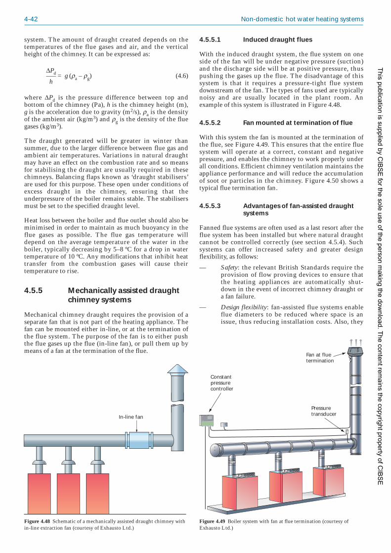
4-42 Non-domestic hot water heating systems
system. The amount of draught created depends on thetemperatures of the flue gases and air, and the verticalheight of the chimney. It can be expressed as:
ΔPd —– = g (ρa – ρg) (4.6) h
where ΔPd is the pressure difference between top andbottom of the chimney (Pa), h is the chimney height (m),g is the acceleration due to gravity (m2/s), ρa is the densityof the ambient air (kg/m3) and ρg is the density of the fluegases (kg/m3).
The draught generated will be greater in winter thansummer, due to the larger difference between flue gas andambient air temperatures. Variations in natural draughtmay have an effect on the combustion rate and so meansfor stabilising the draught are usually required in thesechimneys. Balancing flaps known as ‘draught stabilisers’are used for this purpose. These open under conditions ofexcess draught in the chimney, ensuring that theunderpressure of the boiler remains stable. The stabilisersmust be set to the specified draught level.
Heat loss between the boiler and flue outlet should also beminimised in order to maintain as much buoyancy in theflue gases as possible. The flue gas temperature willdepend on the average temperature of the water in theboiler, typically decreasing by 5–8 °C for a drop in watertemperature of 10 °C. Any modifications that inhibit heattransfer from the combustion gases will cause theirtemperature to rise.
4.5.5 Mechanically assisted draughtchimney systems
Mechanical chimney draught requires the provision of aseparate fan that is not part of the heating appliance. Thefan can be mounted either in-line, or at the termination ofthe flue system. The purpose of the fan is to either pushthe flue gases up the flue (in-line fan), or pull them up bymeans of a fan at the termination of the flue.
4.5.5.1 Induced draught flues
With the induced draught system, the flue system on oneside of the fan will be under negative pressure (suction)and the discharge side will be at positive pressure, thuspushing the gases up the flue. The disadvantage of thissystem is that it requires a pressure-tight flue systemdownstream of the fan. The types of fans used are typicallynoisy and are usually located in the plant room. Anexample of this system is illustrated in Figure 4.48.
4.5.5.2 Fan mounted at termination of flue
With this system the fan is mounted at the termination ofthe flue, see Figure 4.49. This ensures that the entire fluesystem will operate at a correct, constant and negativepressure, and enables the chimney to work properly underall conditions. Efficient chimney ventilation maintains theappliance performance and will reduce the accumulationof soot or particles in the chimney. Figure 4.50 shows atypical flue termination fan.
4.5.5.3 Advantages of fan-assisted draughtsystems
Fanned flue systems are often used as a last resort after theflue system has been installed but where natural draughtcannot be controlled correctly (see section 4.5.4). Suchsystems can offer increased safety and greater designflexibility, as follows:
— Safety: the relevant British Standards require theprovision of flow proving devices to ensure thatthe heating appliances are automatically shut-down in the event of incorrect chimney draught ora fan failure.
— Design flexibility: fan-assisted flue systems enableflue diameters to be reduced where space is anissue, thus reducing installation costs. Also, they
In-line fan
Figure 4.48 Schematic of a mechanically assisted draught chimney within-line extraction fan (courtesy of Exhausto Ltd.)
EBC20
EXHAUSTO
Alarm
ResetOK
Fan at fluetermination
Pressuretransducer
Constantpressurecontroller
Figure 4.49 Boiler system with fan at flue termination (courtesy ofExhausto Ltd.)
This publication is supplied by CIB
SE
for the sole use of the person making the dow
nload. The content remains the copyright property of C
IBS
E

Major components of heating systems 4-43
permit greater freedom in siting of the boilers byallowing unconventional flue routes, includingmultiple bends and long horizontal runs, to beconsidered.
However, designers should also be aware that fanmaintenance can present problems, due to the difficultiesin accessing the fan.
4.5.5.4 Multiple boiler applications
Where multiple, modular, or modulating boiler instal -lations are based on natural chimney draught, the flue andchimney must be calculated for peak loads with all boilersrunning at maximum load. However, this is unlikely tooccur during normal operation since, under part load, onlysome of the boilers will be in use. This can result in anincorrect chimney draught. Mechanically assisted chim -ney draught systems, controlled by a constant pressurespeed regulator, ensure that a correct, constant pressure ismaintained in the flue system, regardless of heat load andthe influences of the surroundings, and will maintainboiler performance.
4.5.6 Flue dilution systems
In some cases, it may not be possible to install aconventional flue system (e.g. due to prohibitive cost,architectural considerations etc.). It then becomesnecessary to discharge the flue gases at a lower level thanwould normally be recommended (although this must stillbe at least 2 m above ground level). In such situations, inorder to prevent causing harm or nuisance to thesurroundings the CO2 content of the flue gases must bereduced, or diluted, to 1% by volume or less.
The required dilution is achieved by discharging thecombustion gases from the boiler(s) into a common headerduct. Each end of this duct is connected to the atmosphereand a fan, positioned downstream of all the flueconnections, is used to draw enough fresh air through theduct that the gases can be discharged safely at a low level.This is shown schematically in Figure 4.51.
When using natural gas as fuel the amount of dilutionnecessary is approximately 10 times. Successful dilutiondepends on thorough mixing of the flue gases and the air,so the header duct must be long enough to ensure thatadequate mixing has occurred prior to discharge; 2 m isusually considered the minimum length required between
the fan and the discharge opening. If this is not possiblethen the volume flow rate of the air will need to beincreased but this can give rise to noise problems and sonoise attenuators may need to be incorporated into theflue design.
The temperature of the diluted gases will also be reduced,usually to below 50 °C, and exit at a velocity of 6–8 m/s.
The inlet and outlet ducts are usually located in the sameexternal wall to ensure a balanced effect against windpressure. Preferably this is a different wall to that in whichthe ducts for the air supply to the burner are located(thought this is not the case in the system shown in Figure4.51) since it is vital to ensure that the discharged fluegases are not re-circulated into the system. To avoid abuild-up of combustion products the intake and dischargeducts should be separated horizontally; a separationdistance of at least 2 m is recommended for a single boilerand this should be increased where multiple boilers areused. If the ducts are separated vertically the dischargeshould be positioned uppermost, to allow the warm fluegases to rise into the atmosphere.
Flue dilution systems are often used with boilers thatalready employ fans. In such cases, the boiler and fluesystems must be balanced so that interaction of the twofans is avoided, often through the use of draughtstabilisers. Note: extreme care must be taken whendesigning a fan dilution system that is to be used with gasfired appliances with premix burners to avoid excessivesuction being applied to the flue outlet connection of theboiler. Advice should be sought from the boiler manufac -turer.
As in all cases where the fan is in contact with flue gases,the fan components must be made of materials that areable to resist corrosion, and the build-up of condensateshould be minimised through appropriate fan design. SeeIGE/UP/10(61) for further details on the design of fluedilution systems.
Figure 4.50 Detail of fluetermination fan (courtesy ofExhausto Ltd.)
Fan
Air flowswitch
Combustionair inlet
Dilution air inlet Discharge Ventilationair outlet
Boilers
Figure 4.51 Schematic of a typical flue dilution system
This publication is supplied by CIB
SE
for the sole use of the person making the dow
nload. The content remains the copyright property of C
IBS
E

4-44 Non-domestic hot water heating systems
4.5.7 Balanced compartments (‘roomsealed’ or ‘balanced flue’)
A balanced compartment arises where an open-fluedappliance is installed with the openings for air intake(both for combustion and room ventilation) and exhaustadjacent to each other at the top of the flue. This meansthat the flue must contain two separate passages, one foringress of air and one for egress of the exhaust gases. Theexhaust gases warm the incoming air as they pass throughthe flue, thereby improving the efficiency of the boiler.The door to the boiler room must be self-closing and fittedwith a draught excluder to ensure that the flue is the onlyroute for ventilation into the room and access to it islimited; hence the room is ‘sealed’ and is known as a‘balanced compartment’.
Termination and height considerations for chimneys frombalanced compartments should follow the same criteria asfor any other chimney system but it is essential that thesystem does not reduce the fire integrity of the roof orbuilding.
Height and termination of all balanced compartmentsmust comply with Chimney Heights: 1956 Clean Air ActMemorandum(54).
4.5.8 Chimney and flue terminals
The terminal is situated at the top of the chimney or flue.Its purpose is to remove the exit point of the flue gasesaway from the turbulence created by the bulk of thechimney, and also place this exit point above the highpressure zone which can cause downdraughts. Theterminal can also reduce the likelihood of water ingress.
The installation should comply with the guidance given inIGE/UP/10(61) and meet the requirements of the Clean AirAct 1993(51). These cover the terminal and outlet dimen -sions and the terminal location, and should ensure thatthe terminal offers minimum resistance to the flow of fluegases, encourages flue gas dispersion, protects againstingress of external objects (e.g. rain, birds) and minimisesdowndraught. IGE/UP/10 gives specific guidance on thepositioning of terminals for open flues, room sealedappliances, mechanical flues, fan diluted flues andbalanced compartments.
For large flues, a terminal may not be required since theycan impede dispersion of combustion products. In all casesit is advisable that the manufacturers of appliances areconsulted to determine the minimum and maximumdraught requirements of the chimney/flue during oper -ation.
As with the rest of the flue system, the terminal materialsmust be able to resist the corrosive nature of the flue gasconstituents.
4.5.9 Flue dampers
A damper or stabiliser is an adjustable valve that is used tointroduce cold air into the chimney in order to lower thetemperature of the flue gases and hence control the naturaldraught. They must be able to withstand the corrosivecomposition of the combustion exhaust so should be
manufactured from at least 1.4301-grade stainless steel(equivalent to ‘304-grade’).
There are limits to the types of chimney into whichdampers may be fitted. IGEM/UP/10(61) prohibits their usein structural chimneys, back-boiler units, gas fires,instantaneous water heaters, room sealed appliances andcombined appliances. The size of appliance also deter -mines where a damper may be fitted in the flue system. Itis advisable to consult with the appliance manufacturerbefore fitting the damper to check that it is suitable for theappliance. In all cases, the use of a damper must notadversely affect performance of the appliance.
Dampers can be operated manually or automatically.Manual dampers tend to have two positions, open andclosed. They can be fitted to standard and fan diluted fluesbut they must not be able to block the flue by more than75% of the cross-sectional area. Automatic dampers areoperated by a drive motor. Position indicators should alsobe fitted for each damper. It is essential that the boiler isnot able to fire when the damper is in the closed position.A required safety feature is that if the linkage betweendamper and motor fails the flue will be left fully open orburner start-up will not be possible.
4.5.10 Condensation
Condensation inside the flue is undesirable due to thecorrosive nature of the combustion products; constituentssuch as sulphur, nitrogen and chlorine will react withwater vapour to form acids. Condensation will occur if thetemperature of the internal flue surface falls below that ofthe acid dew point temperature. In addition, combustiondeposits can form on the flue surface that, during periodswhen the boiler is not operating, can absorb moisture andcause corrosion.
Ideally the flue design should ensure that no condensationoccurs under full load operation. This includes:
— ensuring sufficient insulation to maintain the fluetemperature above the acid dew point temperature
— using materials that are resistant to corrosion
— ensuring the flue gas velocity is high enough toprevent precipitation of deposits inside the flue
— avoiding abrupt changes in direction of the flueroute.
However, even when the above conditions are met,transient condensation can occur on initial start-up with acold chimney. More seriously, permanent condensationcan take place if the chimney operates at a lower load thanthat for which it has been designed. In cases wherecondensation could occur, a condensate drain must beincluded in the flue design, with due care taken to ensurethat the pipework meets all necessary safety standards.This includes ensuring that there is no leakage ofcombustion products into the building and preventingcondensate from running into the terminal.
Where the flue for a condensing appliance discharges intoan existing chimney, the chimney should be lined with acorrosion resistant material, such as 1.4401-grade stainlesssteel (equivalent to ‘316-grade’)(61).
This publication is supplied by CIB
SE
for the sole use of the person making the dow
nload. The content remains the copyright property of C
IBS
E

Major components of heating systems 4-45
4.5.11 Chimney heights and sizing
The height of a chimney is critical to the natural draughtthat can be generated through it, and must be selected tomeet the requirements of the boiler appliance withoutadversely affecting the combustion process. The heightwill depend on several factors, including type of fuel, typeand efficiency of boiler, outlet conditions, height above sealevel of the installation, the physical surroundings andambient temperature ranges.
Legislation within the Clean Air Act 1993(51) specifies thatlocal authorities must approve chimney heights for boilersburning fuels at or above the following rates:
— 366.4 kW for liquid or gaseous fuel
— 45.4 kg/h for solid matter
— any rate for pulverised fuel.
For most heating applications the guidance offered inChimney Heights: 1956 Clean Air Act Memorandum(54),HMIP Technical Guidance Note D1(55), CIBSE TM21(56)
and IGE/UP/10(61). Appendix 1.A2 in CIBSE Guide B(28)
offers examples of how to calculate the necessary heightsof chimneys. Building Regulations Approved DocumentJ(49) may be used for small appliances, although it isunlikely that these would be appropriate for non-domesticsituations.
In the unusual event that the chimney provides positivepressure at the appliance, the construction and sealing ofjoints must be undertaken with care to ensure no leakageof combustion gases(61).
The cross-sectional area of the flue determines the volumeflowrate capacity of the flue. It must be designed toprovide as high a flue gas velocity as possible with as low acooling area as possible. The internal flue surface will alsooffer frictional resistance to the flue gases and this shouldbe taken into account when calculating chimney heights.
4.5.12 Flue sharing
Where chimneys are oversized, or where more than oneboiler is used with one flue/chimney, the inner chimneysurface temperatures may fall below acid dew-pointconditions, even with insulation applied. To avoid theseproblems, it is strongly recommended to install oneflue/chimney per boiler, correctly sized for the maximumpracticable full load flue gases. Where a common flue isused for modular boiler installation, particularlycondensing boilers, advice should be sought from theboiler manufacturer. Generally, however, it is common touse twin-wall insulated sealed flue systems with appro -priate draining facilities at the bottom of the flue todischarge the condensate.
BS 5440: Part 1(66) applies for gas appliances up to 70 kWinput. Situations where two or more appliances areconnected into the same flue require that:
— each appliance is of natural draught type, fittedwith a flame supervision device
— each appliance incorporates a safety control thatwill cause it to shut down before a dangerousamount of combustion products can build up
— the flue size allows complete evacuation ofcombustion products from the entire installation
— access to the chimney for inspection and main -tenance is provided.
4.6 Air supply and ventilation
4.6.1 Introduction
An adequate flow of air to and from the boiler room isneeded for three reasons:
— A sufficient supply of air to the boiler is essentialto ensure that combustion occurs safely andefficiently at maximum output.
— Air is required to ensure proper working of theflue system. The air supply for both theserequirements can be achieved by natural ormechanical means.
— The boiler room must be ventilated to limitoverheating and to prevent any possible build-upof combustion products.
A boiler loses approximately 2% of its heat to thesurrounding room and if this heat is not removed thetemperature increase can damage electronic equipment inthe room as well as being uncomfortable for personnel. BS6880: Part 1(67) recommends a maximum ambienttemperature of 27 °C for working personnel but advisesthat the temperature ratings of electrical items etc. shouldbe checked to ensure that they are not being exceeded.The inlet and outlet vents must be sized in accordancewith the capacity of the boiler and the relevant require -ments are summarised below.
The legislation affecting the combustion air supply andventilation for boiler plant rooms is aimed mainly at smallcommercial appliances (up to 70 kW input net for gasappliances, up to 50 kW rated output for solid fuelappliances and up to 45 kW rated heat output for oil firedappliances).
The legislation is enshrined as Part J of the BuildingRegulations for England and Wales(12). Guidance is givenin Building Regulations Approved Document J:Combustion appliances and fuel storage systems(49).
For Northern Ireland, the equivalent legislation is theBuilding Regulations (Northern Ireland) 2000(68).Guidance is given in Technical Booklet L: Combustionappliances and fuel storage systems(69).
In Scotland the regulations are set down in the Building(Scotland) Regulations 2004(70). Guidance is given in theScottish Building Standards Agency’s Technical Handbook:Domestic(71) and Technical Handbook: Non-domestic(72).
The guidance given here is based upon these requirementsin addition to that given in the following publications:
— IGE/UP/10/Edition 3 (2007): Installation of flued gasappliances in industrial and commercial premises(61)
— BS 6644: 2005 + A1: 2008: Specification forinstallation of gas-fired hot water boilers of rated inputs
This publication is supplied by CIB
SE
for the sole use of the person making the dow
nload. The content remains the copyright property of C
IBS
E

4-46 Non-domestic hot water heating systems
between 70 kW (net) and 1.8 MW (net) (2nd and 3rdfamily gases)(58)
— BS 5410: Code of practice for oil firing; Part 2: 1978:Installations of 44 kW and above output capacity forspace heating, hot water and steam supply purposes(6).
It is important that the latest versions of the abovepublications are consulted when implementing therequirements.
4.6.2 Requirements for gas firedboilers
The following guidance applies to commercial applianceswith rated heat input between 70 kW and 1.8 MW (net).Gas central heating boilers of gross heat input exceeding70 kW should be installed in accordance withIGE/UP/10(61).
4.6.2.1 General requirements
The amount of air required for ventilation must becalculated by taking into account any other fuel-fireddevice that could be affected by the operation of thatappliance(61).
When assessing the ventilation rates and grille sizescorrections should be made to account for additionalfactors as follows(61):
— existence of any combined heat and power devices
— demands for heating or process purposes
— occupants
— heat losses from installed equipment, electricalplant (e.g. electric motors)
— seasonal and climatic conditions.
The air for combustion and ventilation should beprovided in one of the following schemes(58):
(a) low level air supply: one or more openings; highlevel air discharge: one or more openings
(b) low level air supply: by a fan via one or more lowlevel openings; high level air discharge: one ormore openings
(c) low level air supply: by a fan via one or more lowlevel openings; high level air discharge: by a fanvia one opening (note: fans must be so selected asnot to cause a negative pressure (relative to theoutside atmosphere) in the room)
(d) for balanced compartments: high level combinedsupply and discharge systems via purpose-designed (or proprietary) flueing/ventilationsystems based on permanent openings.
Air for ventilation should be taken from areas not pollutedby excessive amounts of dust, debris, noxious gas,propellants, etc. Air intakes must prevent the entry of rain,snow, leaves, debris etc. They should be placed at least0.6 m from any obstruction(61).
Ventilation systems should not cause the space in whichthe appliance is installed to be under negative pressure to
the extent that this could reverse the flow of combustionproducts into the room or appliance(s)(61).
Air should not be supplied and extracted through thesame air duct or grille unless sub-divided throughout itscomplete route(61).
Temperatures within a room, enclosure or balancedcompartment must not exceed the following: 25 °C within100 mm of the floor, 32 °C at mid-height, 40 °C within100 mm of the ceiling (assuming ambient air conditions of15 °C(61). Note: where plant is used in the summer or withhigh ambient temperatures, the ventilation rate/grille sizesmay need to be increased so that the temperature in aplant room does not exceed 40 °C. In some cases, this mayrequire mechanical ventilation(61).
4.6.2.2 Open flued appliances in plant roomsand heated spaces
Ventilation air should be taken directly from outside.However, in some circumstances, where the appropriaterisk assessment has been carried out in order to determinethe suitability of ventilation route, it is allowed to draw airthrough well ventilated areas, e.g. in warehouses etc. Theinternal space which serves as a route for ventilation mustnot be a room used as a bath or shower room, sleepingaccommodation or be a habitable part of a dwelling(61).
Low and high level permanent openings should beprovided in order to enable efficient and safe operation ofthe appliance. The elements of the ventilation system maybe distributed so as to reflect the position of the gasappliance, i.e. air can be ducted to the close vicinity of theappliance(61).
Low and high level ventilation openings should be sizedaccording to Table 4.14(61).
Low level ventilators should be located as low aspracticable and should be installed within 1 m of the floorfor a lighter-than-air gas and within 250 mm of the floorfor a heavier-than-air gases. For a heavier-than-air gases, itis recommended that low level ventilation is at floorlevel(61).
Table 4.14 Minimum air requirements for gas fired appliances(reproduced from IGE/UP/10(61) by kind permission of IGEM)
Position of opening Appliances with rated heat input exceeding 70 kW
At low level (inlet) 4 cm2 per kW total (net) heat input
At high level (outlet) 2 cm2 per kW total (net) heat input
Notes:
(1) For a lighter-than-air gas where the installation has a total net heatinput exceeding 1.8 MW, where high and low ventilation is notpracticable, and the volume of the space is equal to or greater than1 m3 per 2 kW total net input to the appliances(s), it is permitted toinstall 6 m3 per kW of total ventilation at high level only providedmore than one ventilator is fitted. This is not permitted for a heavier-than-air gas.
(2) For a lighter-than-air gas where the plant room does not exceed 1 m3
per 2 kW total net heat input, ducting of ventilation air to low level isnot recommended.
This publication is supplied by CIB
SE
for the sole use of the person making the dow
nload. The content remains the copyright property of C
IBS
E

Major components of heating systems 4-47
The total free area of high level openings into acompartment should be a minimum of 10 cm2 per kWtotal net heat input up to 500 kW. For a total net heatinput exceeding 500 kW, any additional high levelventilation should be a minimum of 8 cm2 per kW totalnet heat input(61).
The high level air handling duct should be sub-divided toprovide separation of the air supply and extract ventilationthroughout its whole length. The total cross-sectional areaof ducting connecting the balanced compartment to theterminal should not be less than the free area of the venti -lation opening as required by the previous paragraph(61).
4.6.2.4 Room sealed appliances
The ventilation requirements for room sealed appliancesin plant rooms, heated spaces and balanced compartmentsshould take account of the heat losses from the installedequipment if the resultant rise in temperature could leadto failure of electrical components. The ventilationsystems should also take into account the heat losses fromelectrical plant(61). The temperature criteria given section4.6.2.1 should be followed(61).
Where both a room sealed and an open flue appliance areto be installed in the same balanced compartment, 50% ofthe total net heat input for the room sealed applianceshould be added to the total heat input for the open flueappliance to obtain the ventilation requirements(61).
4.6.2.5 Mechanical ventilation
Ventilation requirements are given in Table 4.16. Thepurpose of a draught diverter is to ensure an appropriatepressure around the flame. This is achieved by divertingdraughts caused by changes in pressure within theinternal environment or outside the building. The draughtdiverter is usually incorporated within the appliance.
Extract only mechanical ventilation should not beinstalled (i.e. an extract element should not cause anegative pressure within a room or space, in which theappliance is installed)(61).
The operation of fans should be detected by airflow- orpressure-proving and by auxiliary contact in the motorstarter switch gear, and be interlocked with the applianceoperation. The appliance should switch off in case of failurein airflow/pressure-proving or power to the motors(61).
The fan should not react in response to temperaturechanges in a plant room, apart from the case when theappliance switches off due to operation of a clock orspace/process controls(61).
Table 4.15 Minimum free area of air vents in enclosures (reproduced from IGE/UP/10(61)
by kind permission of IGEM)
Flue type Ventilation direct to outside air Ventilation to an internal space/ (cm2 per kW net heat input) / (cm2 per kW net heat input)
High Low High Low
Open 5 10 Not permitted* Not permitted*
Room sealed 5 5 10 10
* Not permitted, except as stated in section 4.6.2.2, paragraph 1.
High and low level ventilation should be provided in theratio of one at high level to two at low level, i.e. one thirdat high level, and two thirds at low level, on any one wall.As far as is practicable, the ventilation grilles should bedispersed on more than one wall, maintaining the 1:2ratio. High level ventilation should be as high aspractical(61).
4.6.2.3 Open flued appliances and roomsealed appliances in enclosures
An enclosure is defined as: ‘a space in which an appli -ance(s) is installed, which is not large enough to enter toperform work other than maintenance via externalaccess’(61).
Preferably, ventilation air should be taken directly fromoutside. Ventilation requirements are shown in Table 4.15.It is assumed that all heat-emitting surfaces (hot pipes,flues or ducts) are insulated(61).
An open-flued appliance installed in an enclosure shouldnot be ventilated into a habitable space of a dwelling orany internal space used as sleeping accommodation or forshowering or bathing (e.g. care taker’s flat in a school).There may be exceptions where results from risk assess -ment calculations allow(61).
4.6.2.3 Open flued appliances in balancedcompartments
A balanced compartment is defined as: ‘a plant room orenclosure for one or more gas appliances, specificallydesigned to draw its combustion air from a point adjacentto the point at which the combustion products aredischarged, the inlet and outlet being so disposed thatwind effects are substantially balanced’(61).
Ventilation construction must be designed so as to enableproper and safe operation of the combustion and dischargesystems(61).
When a compartment is located inside the building thefollowing requirements apply(61):
— There should not be any openings other than thedoor (e.g. a window) that open to the habitablearea.
— For a heavier-than-air gas, appliances should belocated against an outside wall, and either a meansof low level ventilation provided by the designer ora minimum opening of 60 cm2 provided at lowlevel direct to the outside.
This publication is supplied by CIB
SE
for the sole use of the person making the dow
nload. The content remains the copyright property of C
IBS
E
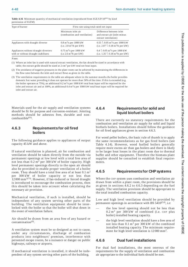
4-48 Non-domestic hot water heating systems
Materials used for the air supply and ventilation systemsshould be fit for purpose and corrosion-resistant. Jointingmethods should be asbestos free, durable and non-combustible(61).
4.6.3 Requirements for oil firedboilers
The following guidance applies to appliances of outputcapacity 45 kW and above.
If natural ventilation is planned, air for combustion andventilation should be taken directly from the outside viapermanent openings at low level with a total free area ofnot less than 0.2 m2 per 300 kW of boiler capacity. Highlevel permanent openings directly to the open air shouldalso be provided to enable proper ventilation of a boilerroom. They should have a total free area of at least 0.1 m2
per 300 kW of boiler capacity or not less than12 000 mm2(73). However, if fan-induced or forced draughtis introduced to encourage the combustion process, thenthis should be taken into account when calculating thenecessary air provision.
Mechanical ventilation, if such is installed, should beindependent of any system serving other parts of thebuilding. The ventilation equipment should be inter -locked with the boiler so that the boiler will shut down inthe event of ventilation failure.
Air should be drawn from an area free of any hazard orcontamination(6).
A ventilation system must be so designed as not to cause,under any circumstances, discharge of combustionproducts into neighbours’ premises, interference withpersonnel escape routes, be a nuisance or danger on publichighways, railways or airports.
If mechanical ventilation is installed, it should be inde -pendent of any system serving other parts of the building.
4.6.4 Requirements for solid andliquid biofuel boilers
There are currently no statutory requirements for thecombustion and ventilation air supply for solid and liquidbiofuels boilers. Installations should follow the guidancefor oil fired appliances given in section 4.6.3.
For wood pellet boilers, the basic rule of thumb is to applythe same recommendations as for gas fired boilers (seeTable 4.14). However, wood fuelled boilers generallyrequire more excess air than gas boilers and there is likelyto be larger heat losses in the plant room due to thermalbuffer and other equipment. Therefore the biomass plantsupplier should be consulted to establish final require -ments.
4.6.5 Requirements for CHP systems
Where the CHP system uses combustion and ventila tion airdrawn from within a plant room, the provisions should beas given in sections 4.6.2 to 4.6.3 depending on the fuelsupply. The ventilation provision should be appropriate tothe total installed combustion capacity.
Low and high level ventilation should be provided bypermanent openings in accordance with BS 5410(5,6), i.e:
— the low level opening should not be less than0.2 m2 per 300 kW of combined (i.e. CHP plusboiler) installed heating capacity.
— the high level ventilation should have a free area ofnot less than 0.1 m2 per 300 kW of the combinedinstalled heating capacity. The minimum require -ment for high level ventilation is 12 000 mm2.
4.6.6 Dual fuel installations
For dual fuel installations, the most onerous of therequirements for the supply of ventilation and combustionair appropriate to the individual fuels should be met.
Table 4.16 Minimum quantity of mechanical ventilation (reproduced from IGE/UP/10(61) by kindpermission of IGEM)
Type of burner Flow rate using total rated net input
Minimum inlet air Difference between inlet (combustion and ventilation) and extract air (inlet minus
extract ventilation)
Appliances with draught diverter 0.8 m3/s per 1000 kW 0.55 +– 0.05 m3/s per 1000 kW(i.e. 2.8 m3/h per kW) (i.e. 2.07 +– 0.18 m3/h per kW)
Appliances without draught diverters 0.75 m3/s per 1000 kW 0.4 +– 0.05 m3/s per 1000 kWwith or without draught stabilisers (i.e 2.6 m3/h per kW) (i.e. 1.35 +– 0.18 m3/h per kW)
Notes:
(1) Where an inlet fan is used with natural extract ventilation, the fan should be sized in accordance withtable; the extract grille should be sized at 2 cm2 per kW total net heat input.
(2) The avoidance of negative pressures in the plant room can be achieved by maintaining the differences inthe flow rates between the inlet and extract flows as given in the table.
(3) The ventilation requirements in the table are adequate where in the summer months the boiler providesdomestic hot water providing it does not operate for more than 50% of the time. If this is exceeded (e.g.the boiler operates at 75%), an additional 0.2 m3/s per 1000 kW total heat input will be required for theinlet and extract air and at 100%, an additional 0.4 m3/s per 1000 kW total heat input will be required forinlet and extract air.
This publication is supplied by CIB
SE
for the sole use of the person making the dow
nload. The content remains the copyright property of C
IBS
E

Major components of heating systems 4-49
4.7 Fuel storage
4.7.1 Gas supply and pipework
4.7.1.1 Natural gas
The legislation governing gas supply to buildings is theGas Safety (Installation and Use) Regulations(73). Theregulations place duties on those working with gas toensure that gas work is carried out safely and the use of gasequipment does not constitute a danger to anyone.
Detailed guidance on the installation of the pipeworksystem for the supply of gas to buildings can be found inthe Institution of Gas Engineers and Managers (IGEM)publication IGEM/UP/2(74). Reference should be made tothe most recent edition of this publication whendesigning, installing and commissioning gas pipeworksystems in buildings. Though the guidance in IGEM/UP/2applies only to new installations, it is recommended thatexisting installations be modified to meet the require -ments of this standard where appropriate. The standardapplies to pipework designed to contain 2nd family gas(e.g. natural gas), and 3rd family gas in the gaseous state(e.g. liquefied petroleum gas (LPG)). Further guidance canbe found in the IGEM publication IGE/UP/10(61).
Natural gas is drawn from a mains supply and so is notstored in bulk on-site. The incoming supply amount mustbe adequate for the appliance and metered in an appro -priate manner. Meters may be required for each separateplant room containing gas burning appliances in order tosatisfy Building Regulations Approved Document L(4) andCIBSE TM39(75). The pressure of the supply is normallyup to 75 mbar and for most commercial buildings this isreduced at the gas meter regulator to 21 mbar beforepassing into the appliances. The pipework should beselected so that pressure losses in pipes do not exceed1 mbar under maximum flow conditions. However, forlarger plants, where the required pressure is greater than21 mbar, a pressure loss of 10% is permitted. IGE/UP/2(74)
should be consulted for further guidance on additionalconstraints of the pipework.
In some cases, such as large installations or where thepressure loss constraints cannot be met, the pressure at theoutlet must be raised. In these cases a ‘gas booster’ isinstalled between the meter and the boiler. This consistsof a compressor driven by an electric motor and mustinclude a pressure relief bypass around the compressorand a non-return valve on the gas supply side of thebooster to ensure that any pressure surges are not trans -mitted back upstream. If there is a risk of disturbing thegas supply or damaging the meter due to changes in thesuction or pressure, another pressure relief valve should beincorporated into the system downstream of the compres -sor. The booster itself is controlled by pressure switchesthat are positioned both upstream and downstream of it. Itis advisable to consult the gas supplier and the gas boostermanufacturer prior to fitting the booster to ensure that itwill operate as desired under all supply conditions.Further guidance on the application of gas boosters can befound in IGEM publication IGE/UP/10(61).
Another component of a natural gas supply system is anemergency gas shut-off and isolation valve. This is
installed in the main gas supply pipe and is in addition tothe manual isolation valves fitted to each individual boiler.This valve is usually operated by a solenoid that will failin the ‘closed’ position if its power supply is interruptedfor any reason.
Safety of gas systems is covered in chapter 1 of CIBSEGuide B(28). Building Regulations Approved DocumentB(76) gives the requirements relating to fire safety withregards to gas service, installation pipes and gas meters.
4.7.1.2 Liquid petroleum gas (LPG)
Bulk storage of LPG is required in either tanks orcylinders; quantities sufficient for up to 6 weeks supplyhas been recommended(77). Further guidance on LPGstorage can be found in the UKLPG Code of Practice 1Part 1: Bulk LPG storage at fixed installations: design,installation and operation of vessels located above ground(78).The boiler installation must comply with the health andsafety, gas safety and building regulations legislation (seechapter 2), and the advice of the LPG supplier should alsobe sought. LPG has a higher calorific value than naturalgas, so the volume flow rate can be lower. The regulatedpressures are slightly higher than natural gas, with butaneusually being regulated to 2.8 kPa and propane to 3.7 kPa.The pressure drop con straint within the pipework is0.25 kPa.
LPG is flammable at concentrations below 11% by volumeand there is a risk of explosion and fire if any leaks areallowed to build up. Thus any installation of LPG insidebuildings should be completely gas-tight and no leakagecan be tolerated during handling. The density of LPG isgreater than air and so any leaked gas will accumulate atlow levels and sink through gaps or openings. Thus areasclose to the LPG storage or boiler installation that lie belowthe tank level, such as drains or cellar openings, must beprotected against the entry of gas and gas detectionsystems should be incorporated into the plant room.
LPG storage tanks should include pressure relief valves butventing of the gas should only be carried out in anemergency as the last resort. Tanks should be positionedaway from buildings, boundaries and permanent sourcesof ignition to avoid risks of the LPG overheating if thebuilding should catch fire; the distance will vary with thecapacity of the tank and can be reduced if a firewall isbuilt between the tank and these other constructions. Thetanks should not be placed in bunds or beneath any formof enclosure (e.g. trees, dense undergrowth). Pipeworkrunning from the storage tank to the building shouldnormally be routed underground and protected againstcorrosion where necessary. Cylinders of LPG, whichcontain lower quantities than the tanks, must be able tostand upright and be secured to the outside of the buildingwall. This area should be well ventilated and at groundlevel, never in a cellar or basement. Refer to the latestedition of the UKLPG Code of Practice 3: Prevention oncontrol of fire involving LPG(79).
Bulk delivery of LPG is by road transport and so the sitemust be accessible for tankers. The storage tank shouldnot be completely filled. Further guidance can be obtainedfrom the latest edition of the UKLPG Code of Practice 2:Safe handling and transportation of LPG in road tankers andtanks containers by road(80).
This publication is supplied by CIB
SE
for the sole use of the person making the dow
nload. The content remains the copyright property of C
IBS
E

4-50 Non-domestic hot water heating systems
As with natural gas, the supply line must have an emer -gency gas shut-off and isolation valve fitted within theplant room and at a point where it will close off the LPGsupply to all boilers using it. The valve is normally a fail-shut solenoid type and should operate on detection of LPGas well as if the power supply is interrupted. Refer to thelatest edition of the UKLPG Code of Practice 15 Part 1:Valves and fittings for LPG services: safety valves(81).
4.7.2 Oil
The types of oil that are normally utilised in heatingsystems are Class C (kerosene) and Class D (gas oil). ClassD tends to be the choice for non-domestic heating appli -cations and Class C for domestic. Both fuels are stored inbulk. Tanks may be constructed out of either steel orpolymer materials and that BS 799: Part 5(82) for steeltanks and BS EN 13341(83) for ‘plastic’ tanks should beconsulted. It is also recommended that fully encompassingindustry tank system standards such as OFTEC StandardsOFS T200(84) and OFS T100(85) are also consulted.
It is essential to locate the storage tank in a bund, orcatchpit, to hold any spillage of oil. The bund must beable to retain the full capacity of the tank in the event ofthe tank leaking its entire contents. Chapter 2 considersthe legislation to control pollution risks should a spillageoccur. BS 5410: Part 1(5) describes the construc tion ofcatchpits (bunds) that should be used where there is a riskof contamination to water supplies. Due to the vagaries ofon-site risk assessment, it is best practice always toprovide secondary containment. For installations largerthan 45 kW guidance should be sought from the local fireauthority and comply with the Control of Pollution (OilStorage) Regulations 2001(86).
Building Regulation J5(49) concerns the protection ofliquid fuel storage systems and applies for any buildingsupplied by oil tanks with a capacity over 90 litres.Regulation J5 aims to minimise the risk of the fueligniting in a storage tank due to fire in adjacent orsurrounding buildings. BS 5410: Part 2(6) should beconsulted for guidance on methods of protecting tanks fornon-domestic applications from such fires through theirlocation and construction. This includes the installation offire-resistant fuel pipework protected by a fire valvesystem.
All oil storage tanks must have a vent pipe, designed sothat dirt, debris etc. cannot enter it. This is used todissipate oil vapours that may develop in the tank. Thevent pipe must not be excessively long, in case a head ofoil builds up in it if the tank is overfilled.
Transport of oil to the storage tank is generally by roadand site access for the size of vehicles necessary must beconsidered when planning the location of the tank. Therisk of spillage is greatest during delivery and theFederation of Petroleum Suppliers (http://www.fpsonline.co.uk) provides advice on access to storage tanks anddelivery procedures in order to minimise the safety andpollution risks during this stage. Tanks should not befilled to their maximum capacity but an air gap, termed‘ullage’, left at the top of the tank. An overfill alarmshould be fitted, both audible and visual, to alert thesupplier when the tank is full. The outlet from the tankshould be located at least 76 mm above the base of thetank so that any sludge that has formed does not enter the
pipework and boiler system. The sludge that hasaccumulated at the base of the tank should be cleaned outperiodically, through an appropriately designed andpositioned outlet.
In the UK, Classes C and D fuels should not requireheating for storage but for some Class D fuels heating maybe required to ensure sufficient flow rates. In these casesthe fuel temperature should be maintained between 0 °Cand 5 °C in both the tank and supply pipework, whichshould be thermally insulated. Heating can be provided bysteam/hot water coils or electric immersion heaters.
Classes C and D fuels can be transferred to the boiler fromthe storage tank using single pipes and suction forces areusually adequate to deliver these fuels. Other classes offuel may require pumping and heating systems. Pipeworkcan be of various materials, depending on the fuel type. Afilter is required in the supply line.
In cases where an oil boiler is located in a roof area,additional fuel storage may be required. The main storagecan remain at or below ground level and a short-termstorage tank placed in the actual plant room. Themaximum capacity of this smaller storage tank will belimited for safety reasons and so fuel must be continuouslypumped from the main tank to the plant room. Thepipework system to supply the boiler can vary; selectionwill depend on whether or not the system can use gravityassistance, and the size and number of boilers.
For further information and guidance on the installationand design of oil storage and supply systems to fixedcombustion appliances see the following publications:OFTEC Technical Book 3(87), CIRIA publication C535:Above-ground proprietary prefabricated oil storage tanksystems(88). The website of the Department forEnvironment, Food and Rural Affairs (http://www.defra.gov.uk) and the Environment Agency (http://www.environment-agency.gov.uk) also contain useful infor -mation and should be consulted.
4.7.3 Biomass fuels
Biomass fuels have a lower energy density than fossil fuelsand so relatively large volumes are required to betransported and stored. In addition, these fuels do not flowas readily as oil or gas. This means that particularattention must be given to modes of delivery, both to thestorage unit and from the storage unit to the combustionappliance. The other main factor to consider whendesigning storage facilities is the need to keep the biomassin a suitable condition; this focuses principally on keepingthe fuel dry and preventing bio-degradation.
4.7.3.1 Delivery to storage unit
There are various methods of delivering the biomass tothe storage unit and the method selected will depend onthe quantity and type of fuel being delivered. The mainmechanisms are:
— manual tipping (using sacks, wheelbarrows, etc.)
— tipping from a truck
— dumping from a railway truck
— walking floor trailer
This publication is supplied by CIB
SE
for the sole use of the person making the dow
nload. The content remains the copyright property of C
IBS
E

Major components of heating systems 4-51
— pumping pellets through a tube.
Where gravity can be used to assist delivery the storeshould be designed to allow this by including wherenecessary ramps and underground storage, and ensuringaccess from existing structures is maintained as required.
Access for delivery vehicles and construction/maintenanceequipment must also be considered when planningdelivery to the storage unit.
Figure 4.52 shows delivery of biomass fuel to an under -ground storage unit using a tipping trailer.
4.7.3.2 Storage facilities
Biomass fuel usually absorbs moisture readily, whichcauses a reduction in the heat released when the fuel isburned. It can also naturally biodegrade when in storage,which again leads to a decrease in energy content and canalso lead to the formation of spores, potentially arespiratory hazard. Biodegradation is more likely if thefuel is wet; therefore, in most cases, the fundamentalpurpose of the storage facility is to keep the fuel dry,protecting it from both rain and groundwater.
There are several types of storage unit, such as:
— purpose-built structures
— adapted units, e.g. a feed silo or shipping container
— prefabricated units designed for a specific type ofbiomass fuel.
The storage unit can be built above or below ground level.Below ground makes delivery from tipper trucks easierand releases space above ground for other uses. However,above ground units are usually less costly to build and lesslikely to cause problems with dampness.
Good ventilation is necessary to prevent the build-up ofcondensation, to allow any additional drying of the fuel,and to help prevent the growth of moulds. It can also helpminimise composting of the fuel. In order to minimisecomposting it is advisable to limit stores of chips to about10 m high; if it is necessary to exceed this height then thefuel should be turned-over regularly.
Drainage must also be included in the storage unit, toenable any water to be removed and also to facilitatecleaning of the unit.
Extraction from storage unit
There are several methods of extracting the biomass fuelfrom the storage unit, depending on the store design, andthe type and volume of biomass fuel. These include:
— gravity feed or chute
— screw type auger feed
— conveyor belt
— pneumatic blower
— pumped flow
— bucket conveyor
— front loader
— bucket grab.
If the fuel is able to flow then the storage design shoulddirect the fuel to the position where it is removed.Mechanical handling of the fuel should be kept to aminimum since some fuels can disintegrate and becomeunusable.
Safety
Fire is a significant risk for a biomass boiler system, eitherstarting within the fuel store or spreading from the boilerto the fuel store.
An additional reason for preventing composting is that itcan cause temperatures within the stored fuel to risesignificantly, which presents a risk of fire. If the storageunit is located within an existing building then a firecontrol system must be put in place.
It is essential to prevent burn-back (i.e. combustion alongthe fuel transport systems) from the boiler to the store offuel. The level of protection against this should beincreased if the fuel is stored within a building rather thanisolated outside.
Further information and a list of useful British Standardscan be found at the Biomass Energy Centre website(http://www.biomassenergycentre.org.uk). Other sourcesof information include BSRIA Guide BG1/2008(7) andHVCA TR/38: Guide to Good Practice — Installation ofBiofuel Heating(89) and CIBSE Knowledge Series KS10:Biomass heating(90).
4.7.4 Liquid biofuels
The production of biofuels is summarised in section4.2.10.
The storage system for liquid biofuels requires the samecomponents as for fossil fuels, i.e. tank, gauge, isolationvalve and filter. The pipework from the tank to thebuilding is usually 10 mm diameter copper tubing.However, there are some differences in storage treatment.These arise because, unlike fossil fuels, biofuels degradeover time (e.g. vegetable oil has a storage life of up to 12
Figure 4.52 Biomass fuel delivery at Westgate Plaza, Barnsley (courtesyof Econergy Ltd. (www.econergy.ltd.uk))
This publication is supplied by CIB
SE
for the sole use of the person making the dow
nload. The content remains the copyright property of C
IBS
E

4-52 Non-domestic hot water heating systems
months(91)). The degradation can be influenced by severalfactors including oxygen, light, heat and heavy metal ionsand the following recommendations should be noted:
— the storage temperature should be kept below10 °C
— the fuel should only be heated immediately priorto use
— the storage tanks should be photoresistant
— the tank should be filled up, to prevent oxygenentering
— condensed water that results from temperaturefluctuations should be drained out
— contaminants must be kept out
— metals or metal compounds that can oxidiseshould not be used
— a sedimentation zone should be taken into account
— biofuels should not be stored for longer than sixmonths.
Whether the biofuels require thermal treatment or notwill depend on the type of blend and the method of itsmanufacture. The temperature that is mentioned instandards is the ‘cold filter plugging point’ (CFPP), whichis usually 5 °C lower than the cloud point. In the UK, –15 °C is specified as the CFPP. The CFPP for rapeseedmethyl ester (RME), which is derived from vegetable oils, isclose to this temperature so it is likely that B100 as well asany blend of RME with kerosene or gas oil should bestorable without the need for heating. Fatty acid methylester (FAME) has a higher CFPP, so storage of B100 andsome other blends is likely to require heating of thestorage tank and supply pipework if the fuel is stored in anexposed area. In addition, the tank and pipework shouldbe thermally insulated.
Where FAME processed from cooking oil is mixed withkerosene, a 50% blend is considered to be the upper limitof biodiesel that can be reliably stored without the needfor trace heating. However, the upper limit is not as muchwhere this extender is mixed with gas oil; blends with upto 20% FAME are considered to be stable. In addition tocausing precipitation in the oil, low temperatures can alsolead to the formation of ice in liquid biofuels since, unlikemineral diesel and kerosene, they readily absorb water.Thus it is important to avoid water ingress into the storagetank.
Another potential problem with blended oils is that theymay separate over time. Biodiesel is denser than diesel orkerosene and does not mix readily with the gas oil andkerosene with which it is mixed and so it may sink to thelower part of the storage tank if not intimately mixedinitially. ‘Splash blending’ in the delivery tanker does notproduce a well mixed blend and so should not be used asthe sole means of mixing.
References1 Laws S The development of combustion in association with the
market growth of commercial low water content gas condensing boilersin the United Kingdom (April 2006)
2 Day AR, Ratcliffe MS and Shepherd KJ Heating Systems. Plantand Control (Chichester: Wiley Blackwell) (2003)
3 Condensing technology Viessmann Technical Series (Telford:Veissmann) (2002) (available at http://www.viessmann.co.uk/dom_tech_series.php) (accessed July 2009)
4 Conservation of fuel and power in existing buildings other thandwellings Building Regulations 2000 Approved Document L2B(London: NBS/Department for Communities and LocalGovernment) (2006) (available at http://www.planningportal.gov.uk/england/professionals/en/1115314110382.html) (accessedAugust 2009)
5 BS 5410: Code of practice for oil firing: Part 1: 1997: Installationsup to 45 kW output capacity for space heating and hot water supplypurposes (London: British Standards Institution) (1997)
6 BS 5410: Code of practice for oil firing: Part 2: 1978: Installationsof 45 kW and above output capacity for space heating, hot water andsteam supply services (London: British Standards Institution)(1978)
7 Pennycook K Illustrated guide to renewable technologies BSRIAGuide BG1/2008 (Bracknell: BSRIA) (2008)
8 BS EN 14214: 2008: Automotive fuels. Fatty acid methyl esters(FAME) for diesel engines. Requirements and test methods(London: British Standards Institution) (2008)
9 BS EN 14213: 2003: Heating fuels. Fatty acid methyl esters(FAME). Requirements and test methods (London: BritishStandards Institution) (2003)
10 BS EN 590: 2009: Automotive fuels. Diesel. Requirements and testmethods (London: British Standards Institution) (2009)
11 BS 2869: 2006: Fuel oils for agricultural, domestic and industrialengines and boilers. Specification (London: British StandardsInstitution) (2006)
12 The Building Regulations 2000 Statutory Instruments 2000 No.2531 as amended by The Building (Amendment) Regulations2001 Statutory Instruments 2001 No. 3335 and The Buildingand Approved Inspectors (Amendment) Regulations 2006Statutory Instruments 2006 No. 652) (London: The StationeryOffice) (dates as indicated) (available at http://www.opsi.gov.uk/stat.htm) (accessed October 2009)
13 Non-Domestic Heating, Cooling and Ventilation Compliance Guide(London: NBS/Department of Communities and LocalGovernment) (2006) (available at http://www.planningportal.gov.uk/uploads/br/BR_PDF_PTL_NONDOMHEAT.pdf)(accessed June 2009)
14 BS EN 14511: 2007: Air conditioners, liquid chilling packages andheat pumps with electrically driven compressors for space heating andcooling (4 Parts) (London: British Standards Institution) (2007)
15 BS EN 378: 2008: Refrigerating systems and heat pumps. Safetyand environmental requirements (London: British StandardsInstitution) (2008)
16 BS EN 1736: 2008: Refrigerating systems and heat pumps. Flexiblepipe elements, vibration isolators, expansion joints and non-metallictubes. Requirements, design and installation (London: BritishStandards Institution) (2008)
17 BS EN 15450: 2007: Heating systems in buildings. Design of heatpump heating systems (London: British Standards Institution)(2007)
18 BS EN 15316-4-2: 2008: Heating systems in buildings. Method forcalculation of system energy requirements and system efficiencies.Space heating generation systems, heat pump systems (London:British Standards Institution) (2008)
19 VDI 4640: Thermal use of the underground: Part 2: 2001: Groundsource heat pump systems (Dusseldorf: Verband DeutscherIngenieure (VDI) (2001)
20 Groundwater cooling systems CIBSE TM45 (London: CharteredInstitution of Building Services Engineers) (2008)
21 Small-scale combined heat and power CIBSE ApplicationsManual AM12 (London: Chartered Institution of BuildingServices Engineers) (1999)
This publication is supplied by CIB
SE
for the sole use of the person making the dow
nload. The content remains the copyright property of C
IBS
E

Major components of heating systems 4-53
22 Teekaram A, Palmer A and Parker J CHP for Existing Buildings— Guidance on Design and Installation BSRIA Guide BG2/2007(Bracknell: BSRIA) (2007)
23 Introduction to large-scale combined heat and power GPG043 (TheCarbon Trust) (1992) (available at http://www.carbontrust.co.uk/Publications/publicationdetail.htm?productid=GPG043&metaNoCache=1) (accessed August 2009)
24 An introduction to absorption cooling GPG256 (The CarbonTrust) (1999) (available at http://www.carbontrust.co.uk/Publications/publicationdetail.htm?productid=GPG256&metaNoCache=1) (accessed August 2009)
25 Installation of combined heat and power HVCA TR/37 (London:Heating and Ventilating Contractors Association) (2008)
26 Building control systems CIBSE Guide H (London: CharteredInstitution of Building Services Engineers) (2009)
27 Teekaram A and Palmer A Variable-flow Water Systems —Design, Installation and Commissioning Guidance BSRIAApplication Guide AG 16/2002 (Bracknell: BSRIA) (2007)
28 Heating ch.1 in Heating, ventilating, air conditioning andrefrigeration CIBSE Guide B (London: Chartered Institution ofBuilding Services Engineers) (2001–2)
29 BS EN ISO 5199: 2002: Technical specifications for centrifugalpumps. Class II (London: British Standards Institution) (2007)
30 Parsloe C Variable flow pipework systems CIBSE KS7 (London:Chartered Institution of Building Services Engineers) (2006)
31 Parsloe C Commissioning variable flow pipework systems CIBSEKS9 (London: Chartered Institution of Building ServicesEngineers) (2007)
32 Flow of fluids in pipes and ducts ch. 4 in Reference data CIBSEGuide C (London: Chartered Institution of Building ServicesEngineers) (2007)
33 The Application of Expansion Joints to Pipework Systems MinikinDesign Book (4th edn.) (Harrogate: Minikin and Sons)(available at http://www.minikins.co.uk/IMG/minikindesignbook4thedition.pdf) (accessed August 2009)
34 Plumbing Engineering Services Design Guide (Hornchurch:Chartered Institution of Plumbing and Heating Engineering)(2002)
35 Oughton D and Hodkinson SL Faber and Kell's Heating andAir-conditioning of Buildings (10th edn.) (Oxford: ButterworthHeinemann) (2008)
36 The Water Supply (Water Fittings) Regulations 1999 StatutoryInstruments 1999 No. 1148 (London: The Stationery Office)(1999)
37 BS 7074-2: 1989: Application, selection and installation ofexpansion vessels and ancillary equipment for sealed water systems.Code of practice for low and medium temperature hot water heatingsystems (London: British Standards Institution) (1978)
38 Parsloe C Pre-commissioning cleaning of pipework systems BSRIAAG1/2001.1 (Bracknell: BSRIA) (2001)
39 Dwyer T ‘Deaeration and dirt separation to control watersystem quality’ Build. Serv. J. 89–92 (September 2007)
40 Sands J Underfloor Heating Systems — the Designers GuideBSRIA Application Guide AG12/2001 (Bracknell: BSRIA)(2001)
41 BS EN 442-2: 1997: Specification for radiators and convectors. Testmethods and rating (London: British Standards Institution)(1997)
42 BS 4856-4: 1997: Methods for testing and rating fan coil units, unitheaters and unit coolers. Determination of sound power levels of fancoil units, unit heaters and unit coolers using reverberating rooms(London: British Standards Institution) (1997)
43 BS 7291-1: 2006: Thermoplastics pipes and associated fittings for hotand cold water for domestic purposes and heating installations inbuildings. General requirements (London: British StandardsInstitution) (2006)
44 BS EN 1264-1: 1998: Floor heating. Systems and components.Definitions and symbols (London: British Standards Institution)(1998)
45 BS EN 1264-2: 2008: Water based surface embedded heating andcooling systems. Floor heating. Prove methods for the determination ofthe thermal output using calculation and test methods (London:British Standards Institution) (2008)
46 BS EN 1264-3: 1998: Floor heating. Systems and components. Floorheating. Systems and components. Dimensioning (London: BritishStandards Institution) (1998)
47 BS EN 1264-4: 2001: Floor heating. Systems and components.Installation (London: British Standards Institution) (2001)
48 Underfloor heating design and installation guide (London:CIBSE/Domestic Building Services Panel) (2004)
49 Combustion appliances and fuel storage systems BuildingRegulations 2000 Approved Document J (London:NBS/Department for Communities and Local Government)(2006) (available at http://www.planningportal.gov.uk/england/professionals/en/1115314110382.html) (accessed August 2009)
50 Table 1: List of approved workplace exposure limits (as consolidatedwith amendments October 2007) EH40/2005 Workplace exposurelimits (London: Health and Safety Executive) (2007) (availableat http://www.hse.gov.uk/coshh/table1.pdf) (accessed August2009)
51 Clean Air Act 1993 chapter 11 (London: Her Majesty’sStationery Office) (1993) (available at http://www.opsi.gov.uk/acts/acts1993/ukpga_19930011_en_1) (accessed June 2009)
52 Environmental Protection Act 1990 chapter 43 (London: HerMajesty’s Stationery Office) (1995) (available at http://www.opsi.gov.uk/acts/acts1990/Ukpga_19900043_en_1) (accessedAugust 2009)
53 Environment Act 1995 chapter 25 (London: Her Majesty’sStationery Office) (1995) (available at http://www.opsi.gov.uk/acts/acts1995/ukpga_19950025_en_1) (accessed June 2009)
54 Chimney heights: 1956 Clean Air Act Memorandum (3rd edn.)(London: Her Majesty's Stationery Office) (1981)
55 Guidelines on Discharge Stack Heights for Polluting EmissionsHMIP Technical Guidance Note (Dispersion) D1 (London:The Stationery Office) (1993)
56 Minimising pollution at air intakes CIBSE TM21 (London:Chartered Institution of Building Services Engineers) (1999)
57 Flues for commercial and industrial gas fired boilers and air heatersBritish Gas IM/11 (London: British Gas) (1989)
58 BS 6644: 2005 + A1: 2008: Specification for installation of gas-fired hot water boilers of rated inputs of between 70 kW (net) and1.8 MW (net) (2nd and 3rd family gases) (London: BritishStandards Institution) (2005/2008)
59 BS EN 303-5: 1999: Heating boilers. Heating boilers with forceddraught burners. Heating boilers for solid fuels, hand andautomatically fired, nominal heat output of up to 300 kW.Terminology, requirements, testing and marking (London: BritishStandards Institution) (1999)
60 BS 5854: 1980: Code of practice for flues and flue structures inbuildings (London: British Standards Institution) (1980)
61 Installation of flued gas appliances in industrial and commercialpremises (3rd edn.) IGE/UP/10 Edition 3 (Kegworth: Institutionof Gas Engineers and Managers)
This publication is supplied by CIB
SE
for the sole use of the person making the dow
nload. The content remains the copyright property of C
IBS
E

4-54 Non-domestic hot water heating systems
62 BS EN ISO 9445: 2006: Continuously cold-rolled stainless steelnarrow strip, wide strip, plate/sheet and cut lengths. Tolerances ondimensions and form (London: British Standards Institution)(2006)
63 BS EN 1856-1: 2003: Chimneys. Requirements for metal chimneys.System chimney products (London: British Standards Institution)(2003)
64 BS EN 1856-2: 2004: Chimneys. Requirements for metal chimneys.Metal liners and connecting flue pipes (London: British StandardsInstitution) (2004)
65 BS 4076: 1989: Specification for steel chimneys (London: BritishStandards Institution) (1989)
66 BS 5440-1: 2008: Flueing and ventilation for gas appliances of ratedinput not exceeding 70 kW net (1st, 2nd and 3rd family gases).Specification for installation of gas appliances to chimneys and formaintenance of chimneys (London: British Standards Institution)(2008)
67 BS 6880-1: 1988: Code of practice for low temperature hot waterheating systems of output greater than 45 kW. Fundamental anddesign considerations (London: British Standards Institution)(1988)
68 Building Regulations (Northern Ireland) 2000 Statutory Rulesof Northern Ireland 2000 No. 389 (London: The StationeryOffice) (2000)
69 Combustion appliances and fuel storage systems The BuildingRegulations (Northern Ireland) 2000: Technical Booklet L(London: The Stationery Office) (2006)
70 The Building (Scotland) Regulations 2004 Scottish StatutoryInstruments 2004 No. 406 (London: The Stationery Office)(2004)
71 Scottish Building Standards Technical Handbook: Domestic(Livingston: Scottish Building Standards Agency) (2009)(available at http://www.sbsa.gov.uk/tech_handbooks/tbooks2009.htm#2) (accessed August 2009)
72 Scottish Building Standards Technical Handbook: Non-Domestic(Livingston: Scottish Building Standards Agency) (2009)(available at http://www.sbsa.gov.uk/tech_handbooks/tbooks2009.htm#2) (accessed August 2009)
73 The Gas Safety (Installation and Use) Regulations 1998Statutory Instruments 1998 No. 2451 (London: The StationeryOffice) (available at www.opsi.gov.uk/si/si1998/98245102.htm)(accessed June 2009)
74 Installation pipework on industrial and commercial premises (2ndedn.) IGE/UP/2 (Kegworth: Institution of Gas Engineers andManagers) (date unknown)
75 Building energy metering CIBSE TM39 (London: CharteredInstitution of Building Services Engineers) (2006)
76 Fire safety — Volume 2: Buildings other than dwelling-housesBuilding Regulations 2000 Approved Document B (London:NBS/Department for Communities and Local Government)(2006) (available at http://www.planningportal.gov.uk/england/professionals/en/1115314110382.html) (accessed August 2009)
77 Combustion systems ch.13 in Installation and equipment dataCIBSE Guide B (London: Chartered Institution of BuildingServices Engineers) (1986) (out of print)
78 Bulk LPG storage at fixed installations: Design, installation andoperation of vessels located above ground UKLPG Code of Practice1: Part 1 (UKLPG Association) (2009)
79 Prevention on control of fire involving LPG UKLPG Code ofPractice 3 (UKLPG Association) (2000) .’
80 Safe handling and transportation of LPG in road tankers and tankscontainers by road UKLPG Code of Practice 2 (UKLPGAssociation) (2009)
81 Valves and fittings for LPG services: Safety valves UKLPG Code ofPractice 15 (UKLPG Association) (1997)
82 BS 799-5: 1987: Oil burning equipment. Specification for oil storagetanks (London: British Standards Institution) (1987)
83 BS EN 13341: 2005: Thermoplastics static tanks for above groundstorage of domestic heating oils, kerosene and diesel fuels. Blowmoulded polyethylene, rotationally moulded polyethylene andpolyamide 6 by anionic polymerization tanks. Requirements and testmethods (London: British Standards Institution) (2005)
84 Steel Oil Storage Tanks and Tank Bunds for use with DistillateFuels, Lubrication Oils and Waste Oils Oil Firing EquipmentStandard OFS T200 Issue 6 (Ipswitch: Oil Firing TechnicalAssociation) (2007).
85 Polyethylene Oil Storage Tanks for Distillate Fuels Oil FiringEquipment Standard OFS T100 (6th edn.) (Ipswitch: OilFiring Technical Association) (2008)
86 The Control of Pollution (Oil Storage) (England) Regulations2001 Statutory Instruments 2001 No. 2954 (London: TheStationery Office) (2001)
87 Installation requirements for oil fired equipment OFTEC TechnicalBook 3 (Ipswitch: Oil Firing Technical Association) (2006)
88 Above ground proprietary prefabricated oil storage tank systemsCIRIA publication C535 (London: CIRIA) (2002)
89 Installation of biofuel heating HVCA Guide to Good PracticeTR/38 (London: Heating and Ventilating ContractorsAssociation) (2008)
90 Biomass heating CIBSE KS10 (London: Chartered Institutionof Building Services Engineers) (2007)
91 German Solar Energy Society Planning and Installing BioenergySystems: A Guide for Installers, Architects and Engineers (London:Earthscan) (2005)
This publication is supplied by CIB
SE
for the sole use of the person making the dow
nload. The content remains the copyright property of C
IBS
E
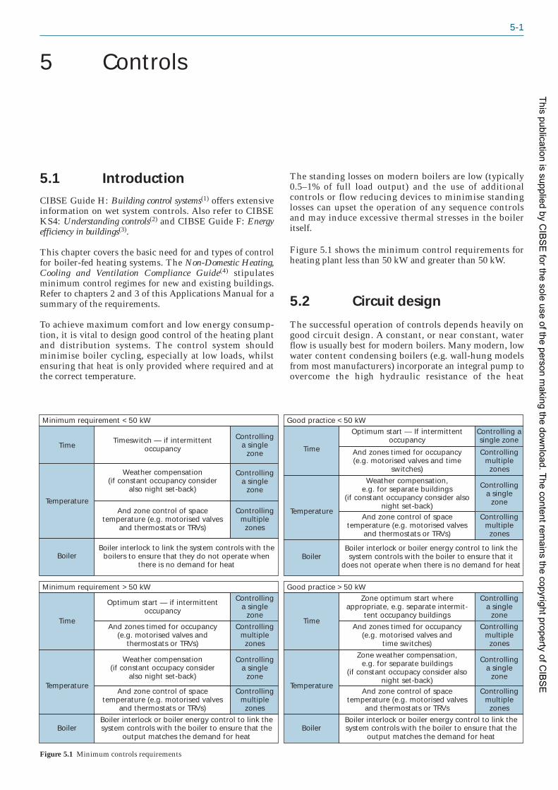
5-1
5.1 IntroductionCIBSE Guide H: Building control systems(1) offers extensiveinformation on wet system controls. Also refer to CIBSEKS4: Understanding controls(2) and CIBSE Guide F: Energyefficiency in buildings(3).
This chapter covers the basic need for and types of controlfor boiler-fed heating systems. The Non-Domestic Heating,Cooling and Ventilation Compliance Guide(4) stipulatesminimum control regimes for new and existing buildings.Refer to chapters 2 and 3 of this Applications Manual for asummary of the requirements.
To achieve maximum comfort and low energy consump -tion, it is vital to design good control of the heating plantand distribution systems. The control system shouldminimise boiler cycling, especially at low loads, whilstensuring that heat is only provided where required and atthe correct temperature.
The standing losses on modern boilers are low (typically0.5–1% of full load output) and the use of additionalcontrols or flow reducing devices to minimise standinglosses can upset the operation of any sequence controlsand may induce excessive thermal stresses in the boileritself.
Figure 5.1 shows the minimum control requirements forheating plant less than 50 kW and greater than 50 kW.
5.2 Circuit design
The successful operation of controls depends heavily ongood circuit design. A constant, or near constant, waterflow is usually best for modern boilers. Many modern, lowwater content condensing boilers (e.g. wall-hung modelsfrom most manufacturers) incorporate an integral pump toovercome the high hydraulic resistance of the heat
5 Controls
Zone weather compensation,e.g. for separate buildings
(if constant occupacy consider also night set-back)
Controllinga single
zoneTemperature
And zone control of spacetemperature (e.g. motorised valves
and thermostats or TRVs
Controllingmultiple
zones
Boiler interlock or boiler energy control to link the system controls with the boiler to ensure that the
output matches the demand for heatBoiler
And zones timed for occupancy(e.g. motorised valves and
time switches)
Controllingmultiple
zones
Zone optimum start whereappropriate, e.g. separate intermit-
tent occupancy buildings
Controllinga single
zoneTime
Good practice >50 kW
Weather compensation(if constant occupacy consider
also night set-back)
Controllinga single
zoneTemperature
And zone control of spacetemperature (e.g. motorised valves
and thermostats or TRVs)
Controllingmultiple
zones
Boiler interlock or boiler energy control to link the system controls with the boiler to ensure that the
output matches the demand for heatBoiler
And zones timed for occupancy(e.g. motorised valves and
thermostats or TRVs)
Controllingmultiple
zones
Optimum start — if intermittent occupancy
Controllinga single
zoneTime
Minimum requirement >50 kW
Weather compensation,e.g. for separate buildings
(if constant occupancy consider also night set-back)
Controllinga single
zoneTemperature
And zone control of spacetemperature (e.g. motorised valves
and thermostats or TRVs)
Controllingmultiple
zones
Boiler interlock or boiler energy control to link the system controls with the boiler to ensure that it
does not operate when there is no demand for heatBoiler
And zones timed for occupancy(e.g. motorised valves and time
switches)
Controllingmultiple
zones
Optimum start — If intermittent occupancy
Controlling asingle zone
Time
Good practice <50 kW
Weather compensation(if constant occupancy consider
also night set-back)
Controllinga single
zoneTemperature
And zone control of space temperature (e.g. motorised valves
and thermostats or TRVs)
Controllingmultiple
zones
Boiler interlock to link the system controls with the boilers to ensure that they do not operate when
there is no demand for heat Boiler
Timeswitch — if intermittentoccupancy
Controllinga single
zoneTime
Minimum requirement <50 kW
Figure 5.1 Minimum controls requirements
This publication is supplied by CIB
SE
for the sole use of the person making the dow
nload. The content remains the copyright property of C
IBS
E

5-2 Non-domestic hot water heating systems
exchanger. Although system distribution pumps will alsobe required, these may need to be hydraulically separatedfrom the boiler itself, e.g. by a low-velocity header (alsoknown as a ‘low loss header’). Therefore, for most applica -tions, systems should be designed as follows.
5.2.1 Single boiler installations
Small, single boiler applications are often provided with asingle pumped circuit as shown in Figure 5.2. This type ofsystem gives good control provided there are no flowreducing devices and the inside and outside sensors
provide compensation by adjusting the low temperature tosuit the load. This type is usually only suitable for heatinga single space. Some thermostatic radiator valves (TRVs)could be added but the load that they control must notexceed 15% of the total.
Where it is necessary to fit flow reducing devices, or thedirect compensation on the boiler has to be limited owingto dew-point acid protection (non-condensing gas and oilboilers), a primary loop circuit should be installed asshown in Figure 5.3. This ensures a constant flow throughthe boiler(s) that is independent of the water mass flow inthe distribution circuit.
Time control/weather compensator
Roomcontrolthermostat
Outsidesensor
System with no flow reducing devices
LoadBoiler
Flowtemperaturesensor
Figure 5.2 Single pumped circuit
Time control/weather compensator
Roomcontrolthermostat
System with TRVs or other flow reducing devices
LoadBoiler
Primarylooppump System
pump
Flowtemperaturesensor
Figure 5.3 Primary loop circuit
Load Load
Flowtemperaturesensor
Roomcontrolsensor
Roomcontrolsensor
Outsidesensor
Optimum start/weathercompensator
Sequence control
Boiler
Boiler
Boiler
Figure 5.4 Typical circuitarrangement with primary loopand variable temperature circuits
This publication is supplied by CIB
SE
for the sole use of the person making the dow
nload. The content remains the copyright property of C
IBS
E

Controls 5-3
5.2.2 Large and multiple boilerinstallations
On larger installations with multiple boilers and circuits itis important to separate the boiler and individual circuitsto avoid any interaction between circuits that coulddestabilise the control strategy. Figure 5.4 shows a typicalarrangement using a primary loop and individual variabletemperature circuits. It should be noted that, although thecircuits are fitted with mixing valves, direct compensationof the boilers may also be included where possible. Somepractical problems may be encountered when mixingdirect boiler compensation with indirect system compen -sation, e.g. the compensated boiler flow temperature maynot match the temperature required for the secondaryflow. It is more usual to use one or the other. This willhelp to prevent excessive cycling of the boilers at lowloads. It is also important to ensure that the bypassconnection of the three-way valves is only fed with returnwater from the circuit that it feeds and not the commonreturn.
Some boilers in existing installations may have a valve inthe system return to prevent water flowing through theheat exchanger when the boiler is not in use, therebyavoiding heat being lost to the chimney. However, manymodern boilers incorporate a fully closing air damper (orequivalent) on the burner, which removes the need for thisvalve.
5.3 Boiler controlsEffective control of boilers is a significant factor inachieving energy efficiency. Inadequate or incorrectapplication of boiler control can add 15–30% to fuelconsumption, even with correctly sized boilers. Thefollowing points should be noted:
— The control of multiple boilers is often impairedby boiler over-sizing.
— The reduced standing losses and improved partload efficiency of modern, well insulated, lowwater content boilers normally allows very simplehydraulic arrangements to be used for multipleboilers.
— Simple layouts may not require the use ofindividual boiler pumps, or automatic isolationvalves, which are the cause of many problemsassociated with the control of multiple boilers.
— Boiler controls must be considered at an earlystage in the design; adding controls after plantlayouts are designed can often result in poorlycontrolled systems. This can result in costly designchanges
5.4 Avoiding excessive boilercycling
Preventing excessive boiler cycling saves energy.Furthermore, NOx and CO emissions are highest duringthe ignition stage and before steady-state conditions havebeen established. Modern boilers usually run more
efficiently at part load than at full load. For these reasons acascade control system (i.e. one that runs the maximumnumber of boilers, even at low modulation rate, to matchthe heat load) is preferable to a step control system (thatusually runs the minimum number of boilers to match theheat load).
Even single boiler systems may suffer from excessivecycling if the boiler is firing to maintain temperature inthe primary circuit when there is no heat demand for thebuilding. In such cases, the boiler firing should becontrolled by the system heat demand, rather than localthermostats, to prevent unwanted cycling.
Boiler anti-cycling controls
There are some after-market boiler anti-cycling controlsavailable that delay boiler firing to reduce unnecessarycycling, usually by lowering the temperature set point atwhich the boiler begins its firing sequence. These devicesmay improve the efficiency of an on/off boiler with a poorcontrol system, but are of no benefit to a modern high/lowor modulating boiler, and no substitute for a well-designedcontrol system with the anti-cycling controls mentionedabove. It should be noted, however, that many of thesmaller boilers do have anti-cycling timers built-in butthese are mainly to prevent excessive strain on the ignitioncircuits rather than to improve efficiency.
5.5 Demand-based boilercontrol and system inhibit
As discussed in section 5.4, demand-based boiler controlsreduce excessive cycling of both boilers and pumps,matching energy consumption more closely to heatdemand. However, response times must be adequate tomeet demand, particularly where the boilers serve hotwater services systems.
Sophisticated strategies can be developed with advancedcontrol systems. Many boilers have in-built extendablecontrol packages that combine direct compensation,optimum start/stop and sequencing. Zone and hot watercontrols can be linked in and thus provide demand-basedboiler control packages.
5.6 Boiler sequence control
There are two main types of sequence control: step control(where individual boilers are switched on or off to matchthe demand) and cascade control (where the load is sharedbetween the maximum number of boilers). The latter isusually a more efficient way of controlling modern boilers,as they often have a better part load efficiency.
5.6.1 Step control
Controlling boilers in sequence:
— matches the load by adjusting the number ofboilers firing
This publication is supplied by CIB
SE
for the sole use of the person making the dow
nload. The content remains the copyright property of C
IBS
E

5-4 Non-domestic hot water heating systems
— improves efficiency by minimising the number ofboilers firing
— minimises boiler cycling
— stabilises temperature variations in the boilercircuit and gives more accurate control of buildingtemperatures.
Step sequence control can be achieved by control of thefollowing parameters:
— Return temperature: constant temperature boilercircuits are often controlled on return temper -ature, especially if they include non-condensingboilers that require a minimum return watertemperature.
— Common flow temperature or a combination of flowand return temperature: directly compensated boilercircuits can be controlled in this way.
— Direct compensation related to outside air temperature:this can provide reasonably stable sequencing ofboiler plant. However, it is a totally open loopcontrol and does not, on its own, respond to actualsystem load. It should therefore always be linkedto a demand-based control. Where heating and hotwater are being supplied from a common plantthen compensation must be overridden when hotwater is required. Consideration must be given to‘sinking’ any excess temperature thus generated inthe heating primary circuits, without overheatingthe conditioned space.
The use of a control arrangement that gives hot waterpriority should be considered, or alternatively separate hotwater generation equipment used. See section 5.10 on hotwater controls.
Accurate and stable sequence control depends on thefollowing:
— There must be a constant flow rate through theboiler circuit. Unless the distribution circuit isconstant flow a primary loop single pump circuitmust be used.
— A margin should be allowed between the boilerthermostats and the sequence control set point toprevent interaction. This will take account ofinevitable losses through the primary boiler circuitand any temperature differentials between theboilers.
Sequence selection and priority can be manual orautomatic, based on the time or usage. However, stepcontrol can only load and unload the output in steps orstages.
5.6.2 Cascade control
An alternative device for the control of multiple ormodular boiler installations is the ‘cascade manager’ andconsideration should be given to the use of such a devicewhere the installed boilers allow or are compatible withthis form of control.
Modern modulating premix gas fired condensing boilersreturn their highest efficiency at their minimum output.To take advantage of this, many boiler manufacturers
supply cascade managers as a matched sequence controldevice. Cascade managers differ from sequence controllersin that they use a control strategy that takes benefit fromthe increasing efficiency returned as burner outputreduces.
A general statement to explain this would be that it isgenerally better to operate two boilers at 50% output thanone boiler at full output. Cascade managers are able tomodulate as necessary the output from the boilers undercontrol in conjunction with sequence controlling therebydelivering the needed output in an efficient way. A cascademanager will be programmed with a strategy that suits theparticular boilers that are being controlled.
5.7 Burner controls
Single-stage, two-stage and modulating burners areavailable. Two-stage high/low burners offer better partload efficiency than on/off burners.
Boilers tend to be more efficient at low fire so it is betterto operate the firing sequence as low/low/high/high, ratherthan low/high/low/high.
Modulating burners provide the most efficient part loadoperation as air/fuel ratios can he maintained across theoutput range thereby ensuring high combustion efficiency.However, on forced draught boilers with nozzle mixburners the modulating range has to be limited to ensurethat flue gas temperatures do not drop below the dew-point. The maximum turndown is therefore around1.5–3:1, similar to that of a high/low burner. Full premix-type burners are now starting to be fitted to traditionalforced draught boilers with good results. It has been foundthat turndown ratios can be extended with these burnersso that on condensing boilers, because there are noconstraints on flue gas dew-points, turndown ratios arebeing extended to 5:1 with the possibility of furtherincreases.
5.8 Time controls
Time control should be provided to limit unnecessaryoperation of the plant when heat is not required.
Programmers with separate weekday/weekend settings arenow readily available. Programmable room thermostatscan be an inexpensive and flexible means of providingboth time and temperature zone controls.
5.8.1 Fixed time controls
A time switch provides a simple, robust and easilyunderstood means of saving energy and should have smallintervals (15 minutes or less) for effective operation.
5.8.2 Optimum start/stop control
The Non-Domestic Heating, Cooling and VentilationCompliance Guide(4) stipulates that boilers of capacity100 kW or more should have optimal start/stop control.
This publication is supplied by CIB
SE
for the sole use of the person making the dow
nload. The content remains the copyright property of C
IBS
E

Controls 5-5
Optimum start controls are weather-dependent timeswitches that vary the start-up time in the morning toachieve the building temperature by the required time ofoccupation. Heat-up times are reduced during milderweather, thus saving 5–10% of heating energy. Optimumstart controls can be relatively simple using a singleinternal sensor and a linear delay of start-up. However,sophisticated self-learning units with an external sensorare available. These can also provide optimum stopfacilities to turn the boiler off early at the end of the day inmilder conditions, using the thermal inertia of thebuilding to maintain comfort conditions for the remainderof the occupied period.
The greatest energy savings from optimum start controlare likely to be gained in buildings of lightweightconstruction and with heating systems of low thermalcapacity. Thermally heavyweight buildings are lessinfluenced by external fluctuations and are likely torequire smaller variations in required start-up times.These types of buildings also benefit from night set-backcontrol by a few degrees. Similarly, heating systems with aslow response require a longer preheat time and are,therefore, less likely to realise reduced savings withoptimum start control.
The thermal inertia of the building and its heating systemshould be considered when determining switch-off times.Boiler operation can be terminated early and the thermalmass of the plant and building relied on if somedegradation of inside temperature is acceptable towardsthe end of the occupied period.
5.9 Temperature controls
Good control of space temperature is required for energyefficient operation. Control of space temperature can oftenbe achieved at low cost using thermostatic radiator valves.Reducing the room temperature by 1 °C can reduce thefuel use by around 10%.
5.9.1 Weather compensation
Distribution systems should be weather compensatedunless constant temperature is absolutely necessary.Traditionally, air heater batteries and fan convectors havebeen regarded as requiring constant temperature andvariable flow. However, they respond equally well to com -pensation if a little thought is given in the original systemdesign to air distribution and velocity to prevent draughtsat low temperatures. These components should be kept ona separate circuit to radiators, due to their differentresponse to flow temperature. Compensation reducessystem losses and provides basic space temperaturecontrol, although it will not react to internal gains unless aroom sensor is available to adjust the compensation.Multiple compensated circuits are ideal for zoning abuilding to allow for different occupancy patterns etc.Where different emitters are used, or parts of the buildingare better insulated, the compensator schedule can be setto reflect the differing zonal temperature requirements.For example, by putting fan convectors on a differentcircuit to radiators, compensation slopes can be applied tosuit the emitters’ different response factors.
The flow temperature of compensated circuits reduces asambient temperature increases. This provides basiccontrol of space temperature and reduces distributionsystem losses. The compensator slope is normally linear,often with a maximum and minimum flow temperature.In milder weather, the system operates at lowertemperatures, thus saving energy. Some have non-linearslopes to match heat output more closely to ambienttemperature. Also, where space sensors are fitted many areself-learning and will gradually build a new compensationcurve to suit the dynamics of the space exactly.
A fully integrated zone and boiler control system willdetermine the highest zonal water temperature at any timeand then directly compensate the boiler to achieve thistemperature. Zones requiring lower temperatures willutilise 3-port mixing valves to reduce the temperature inthese zones. Weather compensation can provide low returnwater temperatures in milder weather allowing condens -ing boilers to operate at higher efficiencies.
During start-up with non-condensing boilers, the weathercompensation is normally overridden. For condensingboilers the start-up control needs to be considered. Lowertemperatures and a longer start-up period can improveefficiency but a very long start-up period could proveinefficient.
Space temperature reset of compensators is often desirableto take local heat gains into account.
Proper siting of the external sensor is crucial, since it mustreflect the ambient weather condition. Placing it near thebuilding exhaust, or on a wall exposed directly to solarradiation, can lead to incorrect operation so the sensorshould normally be sited on a north-facing aspect.
Deep plan buildings often require heating at the perimeterduring the winter and mid-seasons, while the core maynot require any heating at all. Where a compensated wetheating system is being used around the perimeter of abuilding in conjunction with an air conditioning system,care must be taken to ensure that there is no interactionbetween systems. Where the compensated circuit has arelatively small duty, primarily to prevent cold downdraughts etc., space temperature control of the heatingmay not be required. Where the perimeter heating has ahigher duty, space temperature control can be difficult dueto differing reaction times for the two systems, and spacetemperature controls sensors need careful siting to preventinteraction between the two systems. Care must also betaken when specifying set-points, dead bands, proportion -al bands etc. In some circumstances, it may be possible tolink the space temperature and air conditioning controls.
5.9.2 Night set-back
These controls reduce or ‘set back’ the temperature duringa given time period and are often part of the weathercompensator controls. This is particularly useful at nightin continuously occupied buildings, e.g. elderly persons’homes. Night set-back provides an alternative to simplyswitching the heating off at night, allowing a minimumtemperature to be maintained during the night and thusproviding energy savings compared with continuousoperation. On heavier structures, it is more economical tomaintain the temperature in the fabric of the building
This publication is supplied by CIB
SE
for the sole use of the person making the dow
nload. The content remains the copyright property of C
IBS
E

5-6 Non-domestic hot water heating systems
overnight rather than relying on reheating the buildingfrom cold at high water temperature and maximum boileroutput.
5.9.3 Zone controls
Heating is often required at different times in differentspaces within a building, and to different temperatures. Asuccessful control system will satisfy these variousrequirements on a zone-by-zone basis. A zone may beregarded as a part of the building whose heating system iscapable of independent control, in terms of time,temperature, or both.
Building Regulations Approved Document L2(5)
recommends that space temperature control, by means ofthermostats, thermostatic radiator valves etc., should beprovided for each part of the system that is required to beseparately controlled. Individual emitters should haveseparate control wherever possible for energy efficientoperation. However, emitters should not have local controlwhere sensors are located for space temperature reset ofcompensators.
5.9.4 Thermostatic radiator valves
Thermostatic radiator valves (TRVs) provide a low-costmethod of local temperature control on individualemitters, particularly where there are high incidentalgains. TRVs are normally 2-port and should be used inassociation with variable speed pumps or pressure-operated bypass to provide good control.
Lockable tamper-proof heads are also recommended.These can either be completely locked on one setting, orprovide a minimum level of control for the adjacentoccupants.
Note that TRVs should never be used as the primary sourceof temperature control but only as ‘trimmers’ to respondto localised load changes.
5.9.5 Motorised valves and roomthermostats
Motorised valves and room thermostats can be used toprovide temperature and/or time control of a zone. Thismethod is probably best used in areas with a small groupof emitters, say totalling over 5 kW. Whereas TRVs arelocated near emitters, the location of the room thermostatcan be chosen to provide better room control. Thermostatscan also control a wider range of emitters than TRVs.Resetting the space temperature for unoccupied periodscan also be more easily achieved.
Further energy savings can be achieved by installing timecontrol in zones using 2-port motorised valves, roomthermostat and time control independent from the mainheating time control. Programmable room thermostats area convenient way of achieving this as they combine theroles of time switch and electronic room thermostat, e.g.by varying the room temperature at different times of theday if required.
Larger zones should also be indirectly weather compen -sated, particularly where a boiler supplies a number ofbuildings or to allow for solar gains on different facades.Multiple secondary circuits should normally be connectedin parallel across a common header so that each one hasthe full heat source available to it. This system is relativelysimple and allows good control to be achieved.
5.9.6 Temperature sensor location
Correct installation of sensors is crucial to the efficientand effective operation of control systems. Poor siting canresult in excessive energy consumption or poor comfortconditions.
Room thermostats and sensors must be positioned:
— around 1.5 m above floor level
— out of direct sunlight
— away from draughts
— away from sources of heat
— not in a partitioned office, if it also serves otheroffices.
Internal sensors for optimum start control should alwaysbe located in the coldest part of the building to signal howmuch heat is still stored in the building.
External sensors also need careful siting, as follows:
— on a north or north west wall, out of the sun
— in a position which is representative of the zonebeing controlled
— away from heat sources such as openable windows,extract ducts and chimney stacks.
5.9.7 Variable flow control
For more information on variable speed pumped systemsreference should be made to CIBSE KS7: Variable flowpipework systems(6) and KS9: Commissioning of variable flowsystems(7).
Most existing heating systems are constant volume anduse the same amount of energy for pumping powerthroughout the year regardless of the load on the system.Heating systems normally only require maximum flowduring the boost period, which is a small percentage oftotal heating time. Variable speed pumps can respond tothe reduced demand and decrease the flow of the pumps sothat they match the load on the system.
Considerable pumping energy savings and improved spacetemperature control can be achieved by controlling thespeed of distribution system pumps to respond to systemdemand. Pumps are now available with in-built variablespeed drives that provide rapid payback of the additionalcapital cost.
Variable flow control is commonly achieved using 2-portcontrol valves and a controller monitoring the differentialpressure across the pump or maintaining constantpressure at the system extremities (using remotedifferential pressure sensors). The pump speed is then
This publication is supplied by CIB
SE
for the sole use of the person making the dow
nload. The content remains the copyright property of C
IBS
E

Controls 5-7
controlled using a variable speed drive to maintain aconstant differential pressure. Installation costs are alsoreduced as coil bypass pipework and regulating valves canbe eliminated.
However, care must be exercised when using variablespeed pumps to ensure that temperature control sensorsare not assuming false load information as a consequenceof variable flow.
Variable speed pumps should not be used:
— on boiler circuits where the boiler manufacturerrequires that a constant full flow be maintained
— where proportional and reset controls rely onconstant flow rates for accurate control.
5.10 Hot water controlsAlthough this Applications Manual does not deal with hotwater generation there will be occasions, especially inexisting buildings, where the heating and hot water aregenerated from the same boiler plant. The following istherefore included for information to enable the designerto achieve an integrated control package.
Hot water generators and calorifiers should have time andtemperature controls as recommended in BuildingRegulations Approved Document L(5). The controlsshould be capable of holding the water temperature towithin ±3 °C of the set point temperature. The controlsshould also include a time switch to turn off the heatingsource and any circulating pumps (both primary andsecondary) during periods when hot water will not beneeded.
As many boilers will be controlled with directcompensation there will be times when the boiler flowtemperatures will be too low to generate sufficientdomestic hot water storage temperature. It is thereforebest to use a hot water priority system where the heatingdistribution is inhibited whilst hot water is being
produced. The boiler temperature can be raised duringthis period to give adequate recovery but without fear ofoverheating the building. It is essential that with thissystem the calorifier is capable of rapid recovery becausethe heating is off during this period. A recovery time of15–30 minutes is usually acceptable without causing anynoticeable discomfort in the space.
Segregation of hot water generation from heating systemsis recommended. Where possible, hot water should begenerated locally to minimise distribution losses. Tominimise the risk of Legionella, hot water should be storedat 60 °C and distributed such that a temperature of 50 °C isachieved within one minute at outlets.
References1 Building control systems CIBSE Guide H (London: Chartered
Institution of Building Services Engineers) (2009)
2 Understanding controls CIBSE KS4 (London: CharteredInstitution of Building Services Engineers) (2005)
3 Energy efficiency in buildings CIBSE Guide F (London:Chartered Institution of Building Services Engineers) (2004)
4 Non-Domestic Heating, Cooling and Ventilation Compliance Guide(London: NBS/Department of Communities and LocalGovernment) (2006) (available at http://www.planningportal.gov.uk/uploads/br/BR_PDF_PTL_NONDOMHEAT.pdf)(accessed June 2009)
5 Conservation of fuel and power Building Regulations 2000Approved Document L2A: Conservation of fuel and power in newbuildings other than dwellings; Approved Document L2B:Conservation of fuel and power in existing buildings other thandwellings (London: NBS/Department for Communities andLocal Government) (2006) (available at http://www.planningportal.gov.uk/england/professionals/en/1115314110382.html)(accessed June 2009)
6 Variable flow pipework systems CIBSE KS7 (London: CharteredInstitution of Building Services Engineers) (2006)
7 Commissioning of variable flow systems CIBSE KS9 (London:Chartered Institution of Building Services Engineers) (2007)
This publication is supplied by CIB
SE
for the sole use of the person making the dow
nload. The content remains the copyright property of C
IBS
E

6-1
6.1 GeneralThis chapter gives guidance on the installation of lowtemperature hot water (LTHW) systems and ancillaryequipment. It covers the principal items of equipmentincluding the heat sources, circulation and distributionsystem, heat emitters, controls, and associated items.
Those responsible for the installation of such systems orcomponents of systems have a duty to observe the variousstatutory requirements relating to such work. A numberare listed in section 2.2.11. Additional regulations arelisted in section 6.2.
Many of the items of equipment used in heating systemswill be supplied by manufacturers with detailed instruc -tions for the appropriate storage, handling, installation,testing and commissioning of the item. Manufacturers’instructions should always be followed as failure to do somay invalidate warranties, lead to deterioration or damageto the plant during storage prior to setting to work, andmay create hazards for those working on the installationor for other trades and site staff working in the vicinity.
6.2 Legislation and guidanceThe following Acts, Regulations, Approved Documentsand codes of practice relate to installation and testing:
— Building Regulations 2000(1): Parts J (combustionappliances and fuel storage systems), L(conservation of fuel and power) and P (electricalinstallations)
— Building Regulations Approved Document L2A:Conservation of fuel and power in new buildings otherthan dwellings(2)
— Building Regulations Approved Document L2B:Conservation of fuel and power in existing buildingsother than dwellings(3)
— Building Regulations Approved Document P:Design and installation of electrical installations(4)
— Construction (Design and Management)Regulations 2007(5) and Construction (Design andManagement) Regulations (Northern Ireland)2007(6) (‘CDM Regulations’)
— HSE Approved Code of Practice L144: ManagingHealth and Safety in Construction: Construction(Design and Management) Regulations 2007(7)
— Gas Safety (Installation and Use) Regulations 1998(8)
— HSE Approved Code of Practice and guidanceL56: Safety in the installation and use of gas systems
and appliances The Gas Safety (Installations and Use)Regulations 1998(9)
— Control of Substances Hazardous to HealthRegulations 1988(10) (‘COSHH Regulations’)
— Offices, Shops and Railway Premises Act 1963(11)
— Construction (Health, Safety and Welfare)Regulations 1996(12) and Construction (Health,Safety and Welfare) Regulations (NorthernIreland) 1996(13)
— Pressure Systems Safety Regulations 2000(14)
— HSE Approved Code of Practice and guidanceL122: Safety of pressure systems Pressure SystemsSafety Regulations 2000(15)
— Health and Safety at Work etc. Act 1974(16)
— Thermal Insulation Manufacturers and SuppliersAssociation: TIMSA guidance for achievingcompliance with Part L of the Building Regulations(17)
— Electricity at Work Regulations 1989(18)
— Construction (Lifting Operations) Regulations1961(19)
— Environment Agency Pollution PreventionGuidelines PPG27: Installation, decommissioningand removal of underground storage tanks(20).
6.3 Site facilities
6.3.1 Legal responsibilities
The Construction (Health, Safety and Welfare)Regulations 1966(12,13) and amendments, in particular theamendment of 1 April 1974, cover facilities that should beprovided for site works. Site offices are also covered by theOffices, Shops and Railway Premises Act 1963(11).
6.3.2 Access and site accommodation
For installation work on new construction projects theinstallation of the heating system will form a package ofwork that will be coordinated with other works and thesite facilities will be the responsibility of the maincontractor. These responsibilities include:
— welfare arrangements
— site accommodation
— access and delivery arrangements to the site
— access arrangements for installation staff withinthe site.
6 Installation
This publication is supplied by CIB
SE
for the sole use of the person making the dow
nload. The content remains the copyright property of C
IBS
E

6-2 Non-domestic hot water heating systems
Where lifting equipment is required this may also beprovided by the main contractor. The installer shouldensure that adequate lifting facilities are available wellbefore starting work on site, and that these facilities aresuitable for the installation of the heating system, complywith all statutory requirements, and will be available tothe installer when required.
For refurbishment works, particularly where thereplacement or upgrading of the heating system is themain contract, then all of the above will requireconsideration by the installer prior to work beginning onsite.
Before setting-up site accommodation, the followingshould be checked or noted (as applicable).
— Access to the site accommodation should besuitable throughout the duration of the project andshould not be affected by building progress.
— Access should be suitable for the various types ofvehicles (possibly with heavy and wide loads)delivering plant and equipment to the stores andplant rooms.
— Access to sites may require approval by theHighways Authority, including the routing andtiming of the delivery of materials, in particularlarge plant involving the use of mobile cranespositioned on the highway. Access should besuitable for all types of weather conditions,including winter.
— Adequate lighting should be provided for access inwinter working conditions.
6.3.2.1 Welfare facilities
Adequate first aid boxes, accommodation for clothing andthe taking of meals, washing facilities and sanitaryconveniences should be provided according to the numberof persons employed on the site. It is the employer’sresponsibility to ensure that facilities provided complywith the relevant regulations.
6.3.2.2 Lifting facilities
Cranes and hoists may be provided by another contractor,but it is advisable for the LTHW installer to determineconditions for their use. Cranes and hoists may only beavailable when not being used by other contractors, andunless specific arrangements are made for the use of suchplant, delays may occur in offloading and lifting essentialequipment into plant rooms (particularly in the case ofhigh-rise buildings).
6.3.2.3 Scaffolding
Scaffolding may only be available for a limited periodunless otherwise agreed. The availability and theconditions of use of the scaffolding when required for theinstallation of the LTHW systems should be agreed inadvance. Mobile platforms or towers may be providedinstead of, or in addition to, fixed scaffolding. It isadvisable to determine the suitability and the exactconditions of use, together with availability, good surfacesto facilitate movement, responsibility for erection,
possible alterations to suit varying site conditions anddismantling. Particular attention should be given to safeworking procedures for the use of such equipment.
6.3.2.4 Services (water and electricity)
The installer should determine whether sufficient waterand pressure are available for filling and pressure testingthe LTHW system, particularly in high-rise buildings, andthat the quality is sufficient for the purpose. See section7.3.3 for further guidance.
It is essential that adequate lighting is provided and thatall distribution equipment control and plug points complywith the relevant regulations. Electricity for power toolsshould be provided at the correct capacity and voltage. A(230–250 V) supply should not be used for electrical handtools except in workshops, where they should comply withrelevant regulations. When a 110 V supply is not availablefor electrical hand tools, it is essential to provide suitableportable transformers, properly wired with trailing leadsand plug connections. Portable transformers for weldingmachines (230–250 V:400–415 V) should be properlywired with the necessary isolators and fuses. Compliancewith all relevant regulations is the employer’sresponsibility.
6.4 On-site storage andprotection of equipment
6.4.1 Storage
It is essential to provide adequate storage and protectionof equipment on site prior to and during installation inorder to minimise deterioration of the working parts andof the manufacturer’s finishes.
All materials to be installed should be checked to ensurethat they are free from any dirt or debris prior to applyingprotection.
6.4.1.1 Identification and information
All equipment should be clearly identified on arrival atsite and this should be maintained through to projectcompletion. Manufacturers’ installation instructions mustbe retained at the site and all recommendations andprocedures followed. Equipment on site should bechecked to ensure that it is in a suitable condition toinstall.
Each consignment of equipment delivered should bechecked and such items as starter equipment should bereconciled with motor sizes and other plant ancillaryequipment.
Drawings, wiring diagrams, installation operation andmaintenance instructions and keys are often deliveredwith the equipment. It is advisable to collect such itemsand file them away until required to prevent them beingdamaged or lost.
It may be necessary to accept delivery of equipment beforethe building is ready for the installation of the equipment.
This publication is supplied by CIB
SE
for the sole use of the person making the dow
nload. The content remains the copyright property of C
IBS
E

Installation 6-3
It is necessary, therefore, to provide suitable storagefacilities, which should meet the following conditions:
— easy access at all times
— good unloading facilities
— protection against weather
— proper security
— available until such time as the equipment can beinstalled.
It may be necessary to use off-site storage. In such cases, inadditional to checking the items above, the followingadditional points should be considered:
— provision of adequate insurance cover
— additional costs of transportation
— additional handling
— possible need to use lifting equipment for plant
— access to site at a later date.
6.4.1.2 Equipment
It is good practice to have equipment delivered andinstalled at the proper time in relation to the buildingprogress, in order to minimise the interval betweeninstallation and being put into operation. It is advisable tocheck with manufacturers, particularly where major itemsof plant such as boilers, pressurisation equipment, consoleunits etc. are concerned, as to the precautions that need tobe taken if the equipment is likely to stand without beingcommissioned or operated for a prolonged period of time.This may also apply to smaller items incorporatingelectrical equipment such as fan convectors etc. Protectionof equipment delivered to site should be examined forsuitability for site storage purposes and improved asnecessary.
It is advisable to arrange for manufacturers to providelifting points, clearly indicated, so that unloading andhoisting into position can be carried out in accordancewith the Construction (Lifting Operations) Regulations1961(19).
6.4.2 Protection of equipment
Equipment on site should be protected, whether in storageor installed. Satisfactory security arrangements should bemade to prevent unauthorised interference at all stages ofthe project. Control panels and other lockable equipmentshould always be locked when not being worked on andthe keys removed for safekeeping.
Most equipment is provided with a works-painted finish,very often in special colours that are difficult to match bytouching-up on site if damaged by other buildingoperations or allowed to deteriorate due to being exposedto the weather. It may be necessary (and expensive) tocompletely repaint or respray plant before it is acceptablefor handover. It is usually necessary for protective coatingsto be removed from metal areas before welding.
Particular consideration should be given to the protectionof the bearings in electrical, pneumatic and refrigerationequipment to prevent ingress of moisture and dust. The
presence of these, particularly in combination, can alsocause rapid deterioration of electric motor windings,contact points, terminals, switchgear and circuit boards.Such damage may require specialist remedial work withpossible delays in obtaining replacements. Particularattention should be given to the protection of boilers andassociated refractories. The manufacturer’s recommen -dations should be obtained and followed.
It may be necessary to protect equipment, while it isstanding on site, from the effects of moisture by means oftemporary heaters, dehumidifiers, silica-gel or othermeans. In regard to the use of portable gas heaters (whichhave a high moisture content arising from the products ofgas combustion), consideration must be given to theprovision of adequate ventilation, particularly if dryingout electrical equipment.
Large electric motors, compressors, and other suchequipment with ball or roller bearings should beperiodically rotated to reposition the shaft in order toprevent flattening of the bearings.
Equipment must be protected at all times duringinstallation, particularly with regard to control panels andmonitoring consoles since damage and deterioration canoccur if left exposed during installation and connecting upwiring and/or pneumatic systems.
It is recommended that all bearings and moving parts arechecked before running the equipment to ensure adequatelubrication is provided and that the lubricant is free fromcontamination. Manufacturers’ recommendations shouldbe strictly adhered to when using lubricating oils andgrease.
6.4.2.1 Removal of protective coatings
Equipment may be delivered on site with a protectivecoating such as transparent film, grease or varnish. Theprotective coats should be left on as long as possible andthen removed as recommended by the manufacturer toprevent possible damage to the finish or working parts ofthe equipment. Before using chemical cleaners or similarliquids, it should be checked that no damage will becaused to the equipment. This can be done by applyingthe cleaning agent on a small section of the equipment tocheck suitability.
6.4.2.2 Special protection
With the use of many types of chemicals and cleaningagents by other trades in the building industry, it may benecessary to provide special protection of equipment afterit is installed. Polyethylene sheeting, being of petro -chemical base, may prove unsuitable. Care should be takento ensure that the protection allows for the equipment to‘breath’ so that condensation does not occur.
6.4.2.3 Protection of equipment from othertrades
The use of equipment as a platform and as a base forladders, trestles, shuttering and any other such purposesshould not be allowed. As well as being a safety hazard, itinvariably results in damage to the equipment.
This publication is supplied by CIB
SE
for the sole use of the person making the dow
nload. The content remains the copyright property of C
IBS
E

6-4 Non-domestic hot water heating systems
Insulation is always vulnerable to damage and may requirespecial consideration regarding protection from otherservices and trades.
Pipework should not be used as supports for otherservices, as this may cause excessive bending, deflectionand leakage.
6.4.2.4 Care and maintenance
Where equipment is to be operated between start-up andhandover, appropriate arrangements for maintenance andoperational supervision should be made. Particularattention should be given to protecting equipment duringand after installation. Manufacturers’ instructions, such asregular rotation of shafts, must be carefully followed.Where painted finished are protected by removable film,this should be left in position until all work is completed.
6.5 Installation of equipmentManufacturers’ instructions for the storage, unpacking,installation, testing, setting to work and commissioning ofany LTHW equipment must be carefully followed. If thereis any doubt about following the instructions, themanufacturer must be consulted prior to any deviationfrom the recommended procedure.
6.5.1 Foundations and fixings
The intended location of major equipment should bechecked prior to moving the equipment into position toensure availability of safe access and that any structural orbuilding provisions required in advance of installation arecorrect and ready to use. Floor mounted equipment inplant rooms should be installed on plinths of consistentheights to prevent accumulation of water around supportsand fixings.
The intended methods of fixing, levelling and aligningequipment should be determined before moving it intoposition, and sufficiently in advance to enable theappropriate structural or builders’ work provision to bemade. Holding-down bolts or other mechanical items tobe incorporated into the structure should be madeavailable at the appropriate time and checked prior tobuilding-in. In the process of building-in, provisionshould be made to facilitate minor positional adjustments.
6.5.2 Boilers and combustionequipment
6.5.2.1 Location and access of plant
The location of equipment should be such that safeclearances and access are allowed for the purposes ofinstallation, testing, commissioning, operation andmaintenance. In particular, attention should be paid tomatters such as tube cleaning and withdrawal, statutoryinspections, operations of valves and controls, reading ofinstruments and observation of warning signals. Suchoperations should normally be capable of being carried outfrom operating floor level, unless access platforms and
ladders are specifically intended to be used in a particularsituation.
Should equipment that requires maintenance be installedat height then it is the responsibility of the installingcontractor to provide a maintenance and accessibilitystatement to identify the particular requirements neces -sary to undertake the works.
As part of the risk assessment, the designer has aresponsibility under the CDM Regulations(5,6) to eliminate,if possible, risks associated with access for maintenance,plant replacement etc. A plant removal/replace mentstrategy should form part of the design and ultimately beincluded in the O&M manuals.
The location of equipment should also be such that thedesign requirements are met, with particular attention toaspects that might detract from performance, such asexcessively sharp bends, inadequate clear lengths of pipeat measuring devices, or insufficient space to install ormaintain equipment or system elements correctly.
Bases or supports should be provided that:
— allow for controlled expansion or movement
— are sufficient for the maximum possible load
— are approved by a structural engineer if appropriate.
6.5.2.2 Installation of boiler plant
Installation and assembly should be carried out inaccordance with the manufacturer’s instructions, whichshould be supplied with the plant, and with the relevantprovisions of the regulations relating to fuel supplies andwork involving fuel supply systems.
Particular care must be taken throughout the assemblyand installation of boilers, burners and associated items toensure that they are kept in a clean condition andprotected from humidity, debris and any form ofaccidental damage throughout installation and prior tosetting to work.
Care should be taken in the positioning and location of allboiler installations to ensure that adequate fresh air forcombustion is available. Should this not be the case andmechanical ventilation systems are installed then the‘boiler enable’ signal must be interlocked with themechanical ventilation so that the boiler run is inhibitedshould the ventilation either fail or be insufficient.
6.5.3 Installation of fuel storage andhandling plant
There are many factors that should be considered wheninstalling fuel storage and handling systems, dependant onthe type of fuel. For example, the use of biomass boilersraises issues concerning the supply chain for the woodchip/pulp and the transport implications of this fuel onthe local road network, along with the ash handlingsystems needed for the waste products resulting fromcombustion. Fuel oil systems on the other hand havemajor environmental issues for the containment of thefuel, should a breach occur.
This publication is supplied by CIB
SE
for the sole use of the person making the dow
nload. The content remains the copyright property of C
IBS
E
Installation 6-5
These and other similar issues are covered by severalguidance documents as follows:
— CIRIA C535: Above ground proprietary prefabricatedoil storage tank systems(21)
— CIBSE KS10: Biomass heating(22)
— HVCA TR/38: The installation of biofuel heating(23)
— Environment Agency PPG 2: Above ground oilstorage tanks(24)
— Environment Agency PPG 27: Installation, decom -missioning and removal of underground storagetanks(20).
6.5.4 Installation of chimneys andflues
The installation of modern chimneys and flues is aspecialist role and should only be carried out byexperienced operatives, suitably equipped with theappropriate tools.
By their nature, chimneys and flues are erected at heightsso particular attention should be given to the risksassociated from falling objects and falls. Full riskassessments and method statements for this operationmust be approved prior to starting work.
Owing to the aggressive nature of flue gases it is generallyrecommended that flues should be constructed of 316-grade stainless steel.
The designer and installing contractor should give fullconsideration to the requirement for lightning protectionto tall flues and chimneys.
6.5.5 Pipework insulation
The type and thickness of the thermal insulation alongwith its thermal performance should be specified by thedesigner. In specifying insulation materials, the designershould consider the thickness of the product in relation tothe spatial needs of the pipework system.
Insulation of the piped services should not proceed beforethe system has been successfully pressure tested, otherwisethe installing contractor is proceeding at risk.
For required insulation thicknesses refer to the guidancepublished by the Thermal Insulation Manufacturers andSuppliers Association (TIMSA)(17).
6.5.6 Trace heating
Prior to installing ensure that the correct length of traceheating is used so that the protected length of pipework,including ancillary equipment and valves, are adequatelyprotected. Inspect the pipework to ensure that allhangers/supports have been fitted and that the surface isfree from any sharp edges and burrs.
Always carefully read the manufacturer’s instructions toensure that the installation requirements are met.
There are several ways in which pipework can be tracedheated. Typically it is either wound in a spiral around thepipe or run along the pipe in straight lengths. If straightlengths are used then ensure that the trace heating cable isinstalled along the bottom of the pipe.
When fixing the trace heating cable to pipework ensurethat the tape conforms to the manufacturer’s require -ments. If cable ties are used ensure that they are not tootight to avoid damage to the cable.
Prior to installing insulation over the trace heatingelement, ensure that the installation has been electricallytested. An insulation resistance test is the best indicatorthat the installation is compliant.
Cautionary note: trace heating systems must be installedcorrectly to ensure correct operation and to minimise therisk potential for fire and electric shock.
It is essential that continuity testing of the installation iscarried out both prior to and after the insulation has beenapplied.
6.6 Installation of circulationand distributionequipment
All tubes should be reamed after cutting and should befree from rust, scale or other deposits. Tubes should bethoroughly cleaned before erection and open ends shouldbe temporarily closed with purpose-made metal or plasticcaps, or blank metal flanges. Remnants of cut metal shouldnot be left inside piping; it should be appreciated thatpresence of small particles of dissimilar metals insideradiators etc. can promote intense local corrosion. Whensoldering, a water soluble flux should be used, withoutexcess of either solder or flux. When soldering only theminimum amount of solder and flux necessary to ensure agood joint should be used. Any internal residues should becapable of being removed by rinsing or dispersal by thesystems water during normal operation.
Particular attention should be given to the spacing ofpipework supports, especially when using plastic pipe -work, to ensure that no sagging occurs between supports.
Sufficient thermometers and gauges, or test pocketsshould be provided for commissioning and for operatingand maintenance purposes. Items sensitive to dirt, such assmall automatic control values, should be protected bystrainers. Valves, strainers and other pipeline componentsshould be located in accessible positions. All pipingshould be installed at the correct gradient to ensure properventing and draining. Open vent pipes should risecontinually. Provision should be made for the possibilityof easily dismantling the equipment connections forequipment servicing/removal and suitable precautionsshould be taken to prevent transmission of vibration.
Pipework should be aligned at joints and changes of sizeeffected by appropriate means. The use of bushes shouldbe avoided as far as possible.
This publication is supplied by CIB
SE
for the sole use of the person making the dow
nload. The content remains the copyright property of C
IBS
E

6-6 Non-domestic hot water heating systems
Facilities should be provided for emptying the completeinstallation with the exception of small local dips underfloors or in trenches. An emptying pipe of at least 38 mmdiameter with taps or cock should be connected to thelowest point of each section of the circulation mains forwhich isolation control has been provided. Dead legsshould be avoided except where specifically required forcollection and removal of dirt.
Exposure to freezing conditions should be avoided byappropriate precautions. Vent and drain pipes should beprotected against internal corrosion. Pipe materials, pipefittings, flanges, joints, pipe threads, valves and otherpipework accessories should comply with the appropriateBritish Standard.
Care must be taken to ensure that all automatic air ventsare installed in locations that are accessible formaintenance and repair.
6.6.1 Pumps
Pumps, motors and drives should be readily accessible formaintenance and repair.
All drives should be securely guarded in accordance withstatutory regulations. Particular attention should be paidto the pump inlet and discharge connections and thelocation of valves and strainers to avoid excessive pressuredrop, which may affect pump performance. Valves shouldbe fitted to the suction and discharge of each pump, andflap valves should be checked for freedom of movement.Where duplex pump units are to be used, operationalrequirements should be taken into account beforedeciding whether to provide isolation for each pump, orfor the pair of pumps together. Pumps should be checkedbefore installation in respect of internal cleanliness,freedom to rotate, and correct direction of flow.Orientation of the pump shaft should be in accordancewith the manufacturer’s recommendations.
Pump suction and discharge piping should be properlyaligned. It should be supported so as not to impose loadson the pump and so to allow removal of the pump withoutdisturbing the pipework. Pump connections may haveflexible connectors or alternatively the immediatelyadjacent pipework may be provided with flexible anti-vibration hangers. In all cases care should be taken to seethat such devices are not rendered ineffective by incorrectinstallation procedures. Flexible electrical connections tomotors should be provided. Motors should be locatedaway from hot surfaces and such that adequate cooling aircan circulate. Provision should be made for air venting.Pumps should not be installed at the lowest point of asystem, due to accumulation of sediment.
Vibration isolation should be provided where necessary toprevent transmission of noise and vibration. In generalinertia bases should be installed on all large pumps,coupled with spring isolators. Any pipework orcomponents directly in contact with the pump should besupported from the inertia base.
It is generally considered good practice to fit an in-linestrainer to the suction side of the pump, primarily toprotect the pump from entrained debris but also to act as astrainer for the whole system. As an extra consideration,
finer mesh sizes can be used during initial run-up andcleaning, with the final mesh size being incorporated fromcommissioning stage onwards.
Where operation of a system has the potential that flowmay stop completely during operation (e.g. 2-port valvesystems or thermostatic radiator valves (TRVs), consider -ation should be given to preventing overheating of thepump. This can be facilitated by the installation of apressure relief circuit across the flow and return pipeworkor the inclusion of some 3-port valves. It is generallyconsidered that a minimum flow condition of around 15%is required.
6.6.2 Pressurisation equipment
In addition to the general recommendations in 4.3.8, thefollowing particular points apply to pressurisationequipment:
— It should be installed in a frost-free location.
— It should be securely installed on masonry plinthsor other suitable supports arranged to avoid risk ofcorrosion damage. Anti-vibration provision shouldbe made where pumps are incorporated if thelocation is likely to be sensitive in this regard.
— Where gas cylinders are used for pressurisation,provision for safe access and safe handling of gasequipment should be provided.
— Attention is drawn to the need for the details ofany permanent connection to water supply tocomply with the Water Supply (Water Fittings)Regulations 1999(25) (Scottish Water Byelaws2004(26) in Scotland). Ball valves should bechecked for suitability for the available waterpressure.
— Any cold water break tank should be fitted with asuitably piped overflow of at least 19 mm diameter.
— All quick-fill connections and reservoir fill pointsshould be protected by some form of backflowprevention device, such as air breaks, reducedpressure zone (RPZ) valve or similar. Refer toWRAS Water Regulations Guide(27) for furtherinformation.
— A drain valve and lockable isolating valve shouldbe fitted.
— The piping should be arranged so that warm waterdoes not circulate by gravity through the vessel.
— The make-up tank capacity should be kept to aminimum to reduce risks associated with stagnantwater.
— Appropriate precautions should be taken to protectpumps and the internal surfaces of spill tanks andexpansion vessels from corrosion prior to puttinginto operation, and to prevent deterioration offlexible diaphragms.
— All necessary information should be available tofacilitate correct installation and wiring of such.
This publication is supplied by CIB
SE
for the sole use of the person making the dow
nload. The content remains the copyright property of C
IBS
E

Installation 6-7
6.7 Installation of heatemitters
6.7.1 Radiators
Assembly of sectional radiators on site is not recom -mended. Minimum clearance at the back of a radiatorshould be not less than 50 mm, or as recommended by themanufacturer. Clearance underneath radiators should beas required for mechanical floor cleaning, access toelectrical trunking etc. but in no circumstances less than150 mm.
Radiators should be securely fixed, preferably using themanufacturer’s purpose-made brackets or a fixing that isno less satisfactory in instances where the use of themanufacturer’s brackets is not practicable. The method offixing should be appropriate to the construction of themounting surface; particular care is required withlightweight block walls, lined walls, studded partitions etc.At least two supports should be used; column radiatorshaving more than 20 sections should be provided withadditional supports. Radiators should be effectivelyrestrained from being pulled away from the mountingsurface under normal occupancy conditions.
Setting-out of radiator locations should be such that theradiator can function as intended by the design, also withdue regard to coordination with other services andbuilding features (particularly cills and skirting), overallappearance, relationship to pipework and fittings andmethod of drainage and venting. The need to removeradiators for painting should be recognised.
Attention should be given to access for cleaning, especiallyin hospitals and other environments where ease ofcleaning is particularly important. It should be noted thatthe use of bottom opposite end (BOE) radiator connectionsand appropriate supports may enable radiators to beswung downwards for cleaning, without removal. Vacuumcleaning may be used in some cases, particularly with highoutput radiators and other convectors with narrow airpassages.
6.7.2 Other natural convectors
General principles of setting-out and fixing apply as forradiators. The correct relationship to building finishesshould be observed and appropriate sealing used so thatthe convector may function as intended, also that asatisfactory appearance for the complete installation isachieved and wall staining avoided. Use of a proprietarybackplate is preferred. Purpose-made accessories andfittings available from the equipment manufacturer shouldbe used where appropriate. Heating elements should bechecked and any damage rectified, particularly to fins.Covers should fit correctly, be readily removable anddampers (where fitted) operate freely. Care should betaken to protect finishes throughout the installationperiod through to completion. With continuous convec -tors, further specific points require particular attention,including:
— care in setting out; e.g. provision for thermalexpansion, prior check of relevant buildingdimensions etc.
— attention to details which may interfere withmovement of expanding elements or cause noiseon expansion
— access to valves and controls
— use of acoustic baffles at partitions having anacoustic function.
6.7.3 Forced convectors
Unit forced convectors of the wall-mounted fan coil andsimilar types should be installed in accordance with theprinciples indicated above and with particular attention tothe following:
— location in relation to power points etc. such thatthe electrical installation can meet all theappropriate requirements
— avoidance of obstructions to air inlets anddischarges
— access to controls
— where air filters are required, checking that theappropriate type is fitted, correctly installed andaccessible for removal
— anti-vibration devices function correctly and theunit is satisfactorily installed with regard toacoustic considerations.
Suspended and other types of industrial unit heatersshould be installed using purpose-designed brackets andstays as necessary so that loads are carried by theappropriate structural elements and undue movement isprevented. Unit heaters should not carry piping loads andshould be arranged for heater battery removal withoutinterference to pipe supports. Particular considerationshould be given to access for filter changing (whererelevant) and general maintenance. Attention should alsobe given to the location of control system items andremote controls such as recirculation damper actuators inrespect of industrial air heaters and central air heatingplant.
The following recommendations apply to air heaterbatteries in general:
— Air heater batteries on systems with fresh air inputare particularly prone to frost damage, which mayaffect their location and call for protectivemeasurers.
— The required header connections should beestablished and requirements for venting anddrainage taken into account prior to commencinginstallation and piping-up.
— Heater batteries should be internally clean, andopen ends temporarily sealed.
6.7.4 Radiant heating panels
With radiant heating panel systems there is a particularlyclose relationship between system design, systeminstallation and the construction of the building fabric. Inaddition the following should be noted in the context ofsuspended metal ceilings:
This publication is supplied by CIB
SE
for the sole use of the person making the dow
nload. The content remains the copyright property of C
IBS
E

6-8 Non-domestic hot water heating systems
— A satisfactory installation requires careful setting-out and dimensional checking, with particularreference to the coordination of the suspensionsystem with other high-level services, the requiredlocation of heated and unheated panels to achievethe design intent, coordination with luminaires,other ceiling mounted items and building features.
— The heating tube should be installed so as to avoidunacceptably tight bends. Only the recommendedjointing procedure should be used; particular careis required when joining panel heating tubes toLTHW distribution sub-mains, so as to minimisearea reduction at the joint. The intended heatingcircuit arrangement should be followed andprovision made for venting and draining.
— Always follow the manufacturer’s installationinstructions so that adequate provision is made toallow for thermal expansion.
— Site hydrostatic testing of the tubing should takeplace before the ceiling panels are finally put inposition. Sectional testing maybe appropriate onlarge installations.
— Ceiling panels should be installed such that theirthermal and acoustic properties are not impairedand it is important that the thermal properties ofthe building construction above the ceiling panelshould be as intended.
— Provision should be made for access to valves,controls and measuring devices as necessary forcommissioning and maintenance.
— The design of the system should ensure that theheat stratification throughout the occupied spaceis achieved.
— Appearance of the finished ceiling is particularlyimportant in respect of alignment, level andintegrity of finish, both when cold and atoperating temperature.
6.7.5 Underfloor heating
With heated floor systems there is a particularly closerelationship between systems design, system installationand the construction of the floor fabric. Installationsshould follow guidance given in BS EN 1264-4(28) and also,in addition to the actions recommended in section 3.7 ofBS 6880(29), the following should be noted in the contextof installation of heated floors:
— Before commencing installation, the floorconstruction should have been checked forcompliance with the design requirements, and thatall required insulation, damp proof membranesetc. are correctly installed, fully effective and freeof projections that might damage the heatingelements.
— The distance below finished floor level to the baseon which the heating elements are to be installedand the final floor finishes should be confirmed asbeing at least the required minimum screed depth.
— The heating tubes should be carefully set out andfixed in accordance with the specialist suppliers’recommendations and with particular reference tospacing in accordance with design requirements,
observing minimum bending radii, proving forthermal expansion and using continuous tubelengths as much as practicable; embedded jointsshould only be made by approved thermal fusiontechniques.
— Hydrostatic testing should take place such that thesystem had been proven to be mechanically soundand pressure-tight before installation commences.
— With some proprietary flexible pipe systems it isrecommended that screeding takes place with thetubing under pressure.
— The appropriate mix should be established incollaboration with the floor heating specialist;preparation, application and drying out of thescreed should be carefully supervised.
— An appropriate sequence of drying-out and slowwarm-up should be established with the floorheating specialist and carefully followed, and thescreed surface protected from traffic during thisprocess.
— Floor finishes and coverings should not be applieduntil the drying-out sequence is completed. Itshould be appreciated that certain types of floorfinish are susceptible to damage if not laid so as tobe compatible with the floor heating and anyrecommendations of the floor heating specialistconcerning laying of finishes should be followed.
— For underfloor heating using plastic pipe, therecommendations of BS 5955: Part 9(30) concern -ing installation should be followed. Particular careshould be taken to protect tube from damageduring storage and handling, especially when cold,and from degradation by sunlight.
References1 The Building Regulations 2000 Statutory Instruments 2000 No
2531 as amended by The Building (Amendment) Regulations2001 Statutory Instruments 2001 No. 3335 and The Buildingand Approved Inspectors (Amendment) Regulations 2006Statutory Instruments 2006 No. 652) (London: The StationeryOffice) (dates as indicated) (London: The Stationery Office)(2007) (available at http://www.opsi.gov.uk/stat.htm) (accessedJune 2009)
2 Conservation of fuel and power in new buildings other than dwellingsBuilding Regulations 2000 Approved Document L2A (London:NBS/Department for Communities and Local Government)(2006) (available at http://www.planningportal.gov.uk/england/professionals/en/1115314110382.html) (accessed June 2009)
3 Conservation of fuel and power in existing buildings other thandwellings Building Regulations 2000 Approved Document L2B(London: NBS/Department for Communities and LocalGovernment) (2006) (available at http://www.planningportal.gov.uk/england/professionals/en/1115314110382.html) (accessedJune 2009)
4 Design and installation of electrical installations BuildingRegulations 2000 Approved Document P (London:NBS/Department for Communities and Local Government)(2006) (available at http://www.planningportal.gov.uk/england/professionals/en/1115314110382.html) (accessed June 2009)
5 The Construction (Design and Management) Regulations 2007Reprinted March 2007 Statutory Instruments 2007 No. 320(London: The Stationery Office) (2007) (available athttp://www.opsi.gov.uk/si/si200703) (accessed June 2009)
This publication is supplied by CIB
SE
for the sole use of the person making the dow
nload. The content remains the copyright property of C
IBS
E

Installation 6-9
6 The Construction (Design and Management) Regulations(Northern Ireland) 2007 Statutory Rules of Northern Ireland2007 No. 291 (London: The Stationery Office) (2007)(available at http://www.opsi.gov.uk/sr/sr200702) (accessed June2009)
7 Managing Health and Safety in Construction: Construction (Designand Management) Regulations 2007 HSE Approved Code ofPractice L144 (Sudbury: HSE Books) (2007)
8 The Gas Safety (Installation and Use) Regulations 1998Statutory Instruments 1998 No. 2451 (London: The StationeryOffice) (1998) (available at http://www.opsi.gov.uk/si/si199824.htm) (accessed June 2009)
9 Safety in the installation and use of gas systems and appliances. GasSafety (Installation and use) Regulations 1998 HSE ApprovedCode of Practice and Guidance L56 (Sudbury: HSE Books)(2002)
10 The Control of Substances Hazardous to Health Regulations1988 Statutory Instruments 1988 No. 1657 (London: HerMajesty’s Stationery Office) (1988) (available at http://www.opsi.gov.uk/si/si198816.htm) (accessed June 2009)
11 Offices, Shops and Railway Premises Act 1963 Elizabeth II.Chapter 41 (London: Her Majesty’s Stationery Office) (1963)(available at http://www.opsi.gov.uk/acts/acts1963a) (accessedJune 2009)
12 The Construction (Health, Safety and Welfare) Regulations1996 Statutory Instruments 1996 No. 1592 (London: TheStationery Office) (1996) (available at http://www.opsi.gov.uk/si/si199615.htm) (accessed June 2009)
13 Construction (Health, Safety and Welfare) Regulations(Northern Ireland) 1996 Statutory Rule 1996 No. 510(London: The Stationery Office) (1996) (available athttp://www.opsi.gov.uk/sr/sr199605.htm) (accessed June 2009)
14 The Pressure Systems Safety Regulations 2000 StatutoryInstruments 2000 No. 128 (London: The Stationery Office)(2000) (available at http://www.opsi.gov.uk/si/si200001)(accessed June 2009)
15 Safety of pressure systems. Pressure Systems Safety Regulations 2000HSE Approved Code of Practice and guidance L122 (Sudbury:HSE Books) (2000)
16 Health and Safety at Work, etc. Act 1974 Elizabeth II. Chapter37 (London: Her Majesty’s Stationery Office) (1963)
17 TIMSA guidance for achieving compliance with Part L of theBuilding Regulations (Aldershot: Thermal InsulationManufacturers and Suppliers Association) (2006) (available athttp://www.timsa.org.uk/publications.htm) (accessed June 2009)
18 The Electricity at Work Regulations 1989 StatutoryInstruments 1989 No. 635 (London: Her Majesty’s StationeryOffice) (1989) (available at http://www.opsi.gov.uk/si/si198906.htm) (accessed June 2009)
19 The Construction (Lifting Operations) Regulations 1961Statutory Instruments 1961 No. 1581 (London: Her Majesty’sStationery Office) (1961)
20 Installation, decommissioning and removal of underground storagetanks Pollution Prevention Guidelines PPG27 (London:Environment Agency/Scottish Environment ProtectionAgency) (2002) (available at http://www.environment-agency.gov.uk/business/topics/pollution/39083.aspx) (accessed June2009)
21 Teekaram A, Sterne S, Abel B, Elliott C Above ground proprietaryprefabricated oil storage tank systems CIRIA C535 (London:CIRIA) (2002)
22 Ratcliffe M and McClory M Biomass heating CIBSE KS 10(London: Chartered Institution of Building ServicesEngineers) (2007)
23 The installation of biofuel heating HVCA TR/38 (London:Heating and Ventilating Contractors Association) (2008)
24 Above ground oil storage tanks Pollution Prevention GuidelinesPPG2 (London: Environment Agency/Scottish EnvironmentProtection Agency) (2004) (available at http://www.environment-agency.gov.uk/business/topics/pollution/39083.aspx) (accessed June 2009)
25 Water Supply (Water Fittings) Regulations 1999 StatutoryInstruments 1999 No. 1148 (London: The Stationery Office)(1999) (available at http://www.opsi.gov.uk/si/si199911.htm)(accessed June 2009)
26 Scottish Water Byelaws 2004 (Edinburgh: Scottish Water)(2004) (available at http://www.scottishwater.co.uk) (accessedJune 2009)
27 Young L and Mays G Water Regulations Guide (Oakdale: WRCPublications) (2000)
28 BS EN 1264-4: 2001: Floor heating. Systems and components.Installation (London: British Standards Institution) (2001)
29 BS 6880-3: 1988: Code of practice for low temperature hot waterheating systems of output greater than 45 kW. Installation,commissioning and maintenance (London: British StandardsInstitution) (1988)
30 BS 5955-8: 2001: Plastics pipework (thermoplastics materials).Specification for the installation of thermoplastic pipes and associatedfittings for use in domestic hot and cold services and heating systems inbuildings (London: British Standards Institution) (2001)
This publication is supplied by CIB
SE
for the sole use of the person making the dow
nload. The content remains the copyright property of C
IBS
E

7-1
7.1 Introduction
This section provides an overview of the installationtesting, commissioning and maintenance of heatingsystems in general. It should be noted that many compli -mentary documents exist, offering detailed guidance on allaspects of testing, commissioning and maintenance. Thissection offers a brief overview of the processes.
Refer to CIBSE and BSRIA codes and guidance docu -ments for detailed guidance.
7.2 System testing
7.2.1 Objective
It is important to ensure that new or modified pipeworksystems are pressure tested to ensure that any leaks areidentified prior to the system being filled with chemicalsand put into operation. This testing also allows the systemto be filled and tested in a controlled manner where anyleaks could be managed with minimal risk to the fabricand equipment.
7.2.2 Installation verification
Prior to any pressure testing of the system it is importantto carry out a verification process to ensure that the systemhas been inspected and all components are installed to themanufacturer’s requirements. This especially applies toany measurement devices that are installed as theygenerally require to be installed in such a way that theyhave sufficient straight lengths either side so that theiraccuracy can be guaranteed. It should be agreed at thistime to leave out of the system those components that areconsidered either sensitive to excess pressure or sensitiveto the flushing and cleaning process. These items shouldbe clearly identified and stored under clean and dryconditions.
The installing contractor should ensure that this step iswitnessed and fully documented prior to moving on to thenext stage.
7.2.3 System integrity testing
Prior to the setting to work of any heating system it isimportant to prove its integrity so that the risk of floodingis minimised. This action is generally carried out in one oftwo ways:
— Airtightness testing: if the system is to be installed inan area sensitive to water, or is of a critical nature,then it is usually a requirement to first subject thesystem to an airtightness test.
Should an airtightness test be used to prove theintegrity of the system then all due care should betaken to protect site personal from the risk of harmas a system under a pressure test with air has agreat deal of stored kinetic energy (see HSEGuidance Note GS4(1) for further details).
If an airtightness test is undertaken then care mustbe taken to ensure that all risks to personnel areassessed by completion of a risk assessment andimplementation of its findings.
Perceived success of an airtightness test does notguarantee that the system is fully watertight assmall leaks during an air test may go unnoticed.Therefore care should still be taken on filing thesystems for the first time following an airtightnesstest.
— System pressure test (water): whether or not thesystem has been subjected to an airtightness testthe system should be subjected to a traditionalwater pressure test. The installing contractor mustensure that sensitive installed equipment is notsubjected to the pressure test and that any suchequipment is removed or bypassed.
It is generally accepted that, as a minimum, thesystem should be pressure tested at 50% greaterthan its highest working pressure for a period ofnot less than 2 hours.
Care should be taken to ensure that, once thesystem has been filled with water, all necessaryprotection should be taken against the possibilityof freezing during winter months.
The installing contractor should ensure that this step iswitnessed and fully documented prior to moving on to thenext stage.
If pipework has been prefabricated and pressure tested off-site then it is likely that a layer of corrosion has alreadybuilt up on the inside of the pipework. This should becommunicated to the flushing and cleaning agent so that asuitable methodology can be adopted to overcome thecorrosion.
If there is a delay greater than 42 hours between pressuretesting and the start of the flushing process then it isadvisable to leave the system filled with water dosed witha suitable biocide. If circulation can be achieved duringthis period then the system will be better protected due tothe contact with biocide.
7 Testing, commissioning and maintenance
This publication is supplied by CIB
SE
for the sole use of the person making the dow
nload. The content remains the copyright property of C
IBS
E

7-2 Non-domestic hot water heating systems
7.3 System cleaning, flushingand water treatment
7.3.1 Objective
Detailed guidance on flushing and chemical cleaning canbe found in CIBSE Commissioning Codes(2,3) and BSRIAAG1/2001.1: Pre-commission cleaning of pipework systems(4).The following outlines the main steps involved in flushingand chemical cleaning.
To ensure that the heating system is adequately protectedfrom damage caused by debris, welding slag, swarf, hempetc., it is essential that a dynamic flush is carried out at asufficiently high velocity to satisfy the requirements setout in BSRIA AG1/2001. This will require an adequatelyboosted water supply and suitable drain facilities, andcould require the use of the system pumps.
If the system pumps are to be used, it is essential that theyhave been set-to-work and commissioned, and shown to becapable of producing at least 110% of their stated systemdesign duty in order that the flush can be carried out inaccordance with BSRIA AG1/2001.
Where appropriate, sectional velocity checks should becompleted before the flushing programme begins.
7.3.1.1 Discharge license
It is generally a requirement of the local authority that adischarge license be obtained to permit the water used forflushing to be discharge into the foul drain. Sufficienttime must be allowed in the schedule for this licence to beobtained.
In some instances, it is a requirement of the dischargelicense that the actual amount of water discharged to thedrain is measured so that its chemical content can bemanaged by the local water treatment facility.
7.3.1.2 Drainage
Prior to starting the flushing process, adequate provisionmust be made to dispose of the waste water from flushing.Drainage locations should be identified and written intothe method statement for the process.
7.3.2 System cleanliness
Prior to beginning the flushing process all strainersshould be emptied and cleaned, and any sensitiveequipment (e.g. fan coils units, air handling units, boilers,control valves, radiant panels etc.) should be ‘looped-out’,isolated or replaced with stool pieces by the mechanicalcontractor.
If connecting into an existing system, it is important thatthe water quality and the condition of the existing systemare known. It is therefore recommended that bothchemical and microbiological analyses are carried out onthe existing system prior to linking the two systemstogether. Note: full microbiological tests generally takethree weeks.
To ensure that flushing velocities can be achieved throughflow and return sections throughout the system, all endruns (e.g. radiators) must be looped-out by the mechanicalcontractor. Even after looping or isolating it is possiblethat debris may be caught in the dead leg area between theisolation point and the main pipework being flushed.Therefore efforts should be made to avoid the creation ofsuch dead legs when loops are being installed.
7.3.3 Water source for flushing
The water source used for the flushing process should beanalysed to ensure that it does not contain highconcentrations of microorganisms that may be detrimentalto the system being flushed. If there is any doubt aboutthe quality of the supply water then it is recommendedthat it be pre-treated with a suitable biocide, either byinjection or a break tank. It is now common practice toinject the required water treatment chemicals during finalfilling of the system. This guarantees that all parts of thesystem have contact with the water treatment from thestart.
To avoid possible contamination by microbiologicalorganisms and/or solid debris, coils and items of sensitiveplant should not be filled until the chemical cleaningprocess is complete.
Care must be taken to ensure that no cross-contaminationcan occur between the treated system water and the mainswater. The use of an air break or reduced pressure zone(RPZ) valve is required. Further advice on the protection ofthe mains water system can be found in the WRAS WaterRegulations Guide(5).
7.3.4 Dynamic flushing
The objective of dynamic flushing is to remove as muchdirt and debris as possible from the pipework system toreduce the risk of damage or blockage in the future.
This is achieved by increasing the system circulatingvelocities to such a level that 5 mm steel particles wouldbe moved along a horizontal run in the system, thusallowing them to migrate back to the system strainers andsubsequently removed from the system. It is generallyaccepted that the velocities required are those stated in theBSRIA AG 1/2001(4), see Table 7.1, or 110% of the designvelocity, whichever is the greater.
The dynamic flushing process is generally carried outsystematically, section by section, so that the pumps candeliver excess velocity in each section and so that thecleaning process is carried out from the smallest sectionsback towards the larger bore pipework sections.Throughout the process, the water quality is monitored sothat a continuous discharge can be set-up to relieve thesystem of contaminated water, whilst being replenishedwith clean mains water.
For details of the methods available for dynamic cleaning,see BSRIA AG1/2001.1: Pre-commission cleaning of pipeworksystems(4).
This publication is supplied by CIB
SE
for the sole use of the person making the dow
nload. The content remains the copyright property of C
IBS
E

Testing, commissioning and maintenance 7-3
7.3.5 Chemical cleaning
Chemical cleaning is not always necessary. For example,systems installed with copper, plastic or stainless steelpipework generally require only flushing to remove debrisand therefore may not require chemical cleaning.
The chemicals used in the chemical cleaning process canbe both aggressive and harmful to the environment so therequirement for this process should be case-proven ratherthan being carried out as a matter of course.
Once the system has been satisfactorily dynamicallyflushed the next step is to chemically clean the system, ifthis has been shown to be necessary.
It is important that risk assessments and method state -ments be compiled for the flushing and cleaning processas the storage and handling of water treatment chemicalsis subject to COSHH Regulations(6).
Generally, the system pumps would be used to circulatetypically a detergent-based cleaner for a period of at least48 hours, during which time all sensitive equipment mustbe looped-out and isolated.
If a nitrite-based inhibitor is used, it is particularlyimportant that no aluminium components are containedwithin the system.
Once the contact period has elapsed, suspended solids andchemicals are removed by carrying out a balanced flush.This process is continued until such time as all suspendedsolids, chemicals and dissolved iron levels are measured atacceptable levels. Residual corrosion product and chemicallevels are monitored during the process to establish theextent of cleaning and flushing required.
One consideration is the requirement, or not, for thesystem to be chemically cleaned. This decision should bemade by the designer and care should be taken with thechoice of chemicals as many heating systems containaluminium components which are attacked by somechemical cleaning products.
Many systems, due to their simplicity and the fact thatthey have been largely installed with copper, stainless or
plastic pipework, may only require dynamic flushing andtreating. If this is possible, this ‘flushing only’ method ispreferred for many reasons, the most common being nothaving to discharge chemicals to drain.
The installing contractor should ensure that this step iswitnessed and fully documented prior to moving on to thenext stage.
7.3.6 Water treatment
When the balanced flush is completed, it is essential thatthe system be stabilised immediately with 500 ppmbiocide followed by corrosion inhibitor to give a nitritereserve within the range 300–500 ppm.
If the system is not going to be recirculated routinely afterinhibition, a much higher dosage level must be used toallow for this. Any delay between cleaning and inhibition,or any subsequent water loss causing dilution of theinhibitor will create ‘flash corrosion’ on the active metalsurfaces. This will cause a rise in soluble iron, sludgeformation and the need for an expensive re-cleaningprogramme.
On completion of the flushing and cleaning activitiesdescribed above, final water samples should be taken torecord the final water quality and condition. This isespecially important if the heating system in question ispart of a larger system which, when connected, may besubject of an overall water quality audit.
7.3.7 Frost protection
Owing to the fact that the flushing and cleaning process iscarried out prior to the heating system and boilers beingcommissioned, it is essential that provision be made toprotect any equipment and pipework that is susceptible tofreezing during winter months.
Draining down of pipework should be avoided as leavingthe pipework empty, but still damp internally, will causeflash corrosion on internal surfaces.
7.3.8 Static completiondocumentation
All test documentation must be collated and originals setaside for inclusion in the operation and maintenancemanuals.
This documentation should contain as a minimum, thefollowing:
— system component verification sign-off
— system integrity test certificates includingairtightness test if applicable
— flushing and cleaning risk assessments andmethod statements
— incoming water supply analysis
— discharge license
— dynamic flushing certificates, inclusive ofsectional flushing velocities achieved
Table 7.1 Minimum required water velocities (source: BSRIA AG1/2001(4))
Nominal pipe Flushing velocity Flushing volumesize / mm / (m/s) / (l/s)
15 0.96 0.2020 1.00 0.3725 1.03 0.6032 1.06 1.08
40 1.08 1.4950 1.11 2.4565 1.15 4.2580 1.17 5.98
90 1.19 8.10100 1.21 10.47125 1.24 16.41150 1.26 23.98
This publication is supplied by CIB
SE
for the sole use of the person making the dow
nload. The content remains the copyright property of C
IBS
E

7-4 Non-domestic hot water heating systems
— COSHH(6) data sheets for all chemicals used
— flushing discharge record
— chemical cleaning certificates, inclusive ofmeasured levels achieved
— quantities and chemicals used for the watertreatment.
7.4 Pre-commissioning
7.4.1 Preparation for commissioning
It is important that the commissioning process is managedby a competent person. CIBSE Commissioning Code M:Commissioning management(7) provides an overview of therequired management arrangements to ensure systems aresuccessfully commissioned to meet the objectives of theBuilding Regulations.
Prior to balancing and testing of the heating system, it isalso important that the system is confirmed as beingstatically complete. Verification of the documentationlisted in section 7.3.8 should give the necessary confidencethat the system is ready for the pre-commissioning andtesting to commence.
7.4.2 Pre-commissioning inspections
Pre-commissioning is usually a joint responsibilitybetween the installing contractor and the commissioningagent.
The commissioning agent, in conjunction with theinstalling contractor, should complete their pre-commissioning check sheets to ensure that:
— the system is in a clean state
— all control valves are positioned in a manner thatwould allow for proportional balancing
— all manual bypasses/flushing bypasses have beenisolated
— all commissioning stations/double regulatingvalves are correctly installed and set open
— all electrical checks to motors/pumps/boilers havebeen satisfactorily executed
— method statements and risk assessments for thebalancing works are in place and approved
— the system is handed over to the commissioningagent for their control of operation during thebalancing period
— any works still outstanding on the system havebeen fully identified, recorded on a system ‘to-do’list (Note: it must be ensured that such works willnot be detrimental to the commission ing process).
For details of all individual inspections required, seeCIBSE Commissioning Code W: Water distributionsystems(3), section W5.6 (‘System checks’).
7.4.3 Setting to work: pumpedcircuits
Once the system has been successfully filled and vented, itis imperative that the system circulation is achieved andsubsequently maintained. Therefore timely setting towork of the system benefits the maintaining of the systemwater quality.
The culmination of this activity is to ensure that thesystem is operating in a safe manner and that water iscirculating to all parts of the system, albeit that the systemstill requires balancing and commissioning.
For detail of what is required during this activity, refer toCIBSE Commissioning Code W: Water distributionsystems(3).
7.4.4 Setting to work: boilers
Prior to initially firing the boilers, it is important toensure that safety precautions and interlocks are in placeto protect both the site personnel and the system. Broadly,as a minimum, the following is a list of items, whereapplicable, that would require checking:
— fuel oil system is purged, operational and containssufficient fuel for commissioning
— gas pipework has been purged and the booster setis operational
— oil/gas pressure control/regulation valves areinstalled and set
— boiler primary pressure relief valves are set andactive
— flue is installed, clear and insulated where required
— flue dilution fan is installed, operational andinterlocked with boiler controls
— building management system is operational and allhigh/low limits and interlocks are tested andoperational
— boiler room ventilation or air path for combustionis proven and available.
Initial boiler firing and commissioning should be carriedout strictly in accordance with the manufacturer’srecommendations, and by suitably qualified operatives.
7.5 Commissioning
7.5.1 Initial survey
Prior to any proportional balancing being carried out it isimportant to carry out and fully document an initialsurvey of all loads, whilst their controls are set at ‘full flowto load’. This information is particularly useful as areference should issues arise during balancing.
The information required for the initial survey is:
— pump test (including ‘closed head test’) results
— system schematic
This publication is supplied by CIB
SE
for the sole use of the person making the dow
nload. The content remains the copyright property of C
IBS
E

Testing, commissioning and maintenance 7-5
— flow measurements recorded at all main branchvalves
— flow measurements recorded at all terminal loads
— identification of branch, main branch and systemindex.
These results should be compared with the system designflowrate and the system total should be measured in theregion of 110% of the system design total volume forbalancing to commence.
Should this initial survey show that the system total isbelow 100% of its design value then balancing should notcontinue until referred back to the designer and approvalgiven.
Detailed analysis of the initial survey may show flaws withthe system/installation. Issues that may arise and requireremedial action include:
— incorrectly sized pump impellor has been installed
— pump incorrectly sized for system pressure drop
— pipework sizing incorrect
— terminal coil pressure drops excessive
— 2-port/3-port valve pressure drops excessive
— strainer mesh size incorrect.
7.5.2 Balancing and testing
7.5.2.1 General considerations
As described in section 3.6, there are a number of differingstyles of heating system, each with their own nuances withregards to commissioning. This section sets out therequirements and general considerations for balancing, aswell as some of those for the various types of system.
Each of the system types requires pre-commissioning to acommon standard to ensure that the system is in a fit statefor balancing to proceed. This would generally involve thefollowing to have been undertaken:
— the system has been pressure tested
— the system has been flushed and cleaned torecognised standards.
— the system has been filled and fully vented
— pre-commissioning has been carried out anddocumented
— the pressurisation set (if applicable) has beencommissioned and is operational
— the results of the initial survey have been fullydocumented and the total flowrate is within theacceptable range.
7.5.2.2 Proportional balancing: general
The primary objective for proportionally balancing theheating system is to ensure that a systematic procedure hasbeen applied to the heating system so that the flowratesthroughout the system meet the flow requirements of the
design. The accuracy of the flowrate balancing required tomeet this objective depends on:
— assumptions made during the design for theheating loads for the space
— the performance characteristics of the heatingterminal devices.
Proportional balancing is applied to both constant andvariable flow systems but must be carried out in thesystem’s full flow condition and, in some cases, balancingof the final termination device (e.g. radiator systems) iscarried out as a heat balance.
The method and techniques for carrying out proportionalbalancing of heating systems is documented in CIBSECommissioning Code W(3) but it is worth stating that, ingeneral, trying to achieve a proportional balance tounnecessarily close tolerances will incur unnecessarilyhigh commissioning costs with little or no practicalbenefit to the client. The designer should therefore specifythe tolerances that are required to achieve the designintent but, as a general rule, tolerances such as thoseshown in CIBSE Code Commissioning W should beapplied (see Table 7.2).
Consideration must be given to the performance effect ofthe terminal devices as the heat transfer performance ofterminal devices and other heat exchangers is influencedby water flowrate in a non-linear manner. In some cases,large variations in flowrate can only have a small influenceon the heat exchange performance, see Table 7.3.
Table 7.2 Tolerances for flowrate balancing in heating systems (fromCIBSE Commissioning Code W(3))
Component Tolerances for stated performance effect / %
Low Medium
Terminal units where flow rate is <0.1 l/s ±15 ±10
AHU coils where flowrate is <0.1 l/s ±10 ±7.5
Branch valves ±10 ±7.5
Main branches –0 /+10 –0 /+10
Table 7.3 Flowrate deviation, performance effect and typical installationapplications (from CIBSE Commissioning Code W(3))
Flowrate Performance Typical installation/ applicationdeviation effect
Large Low LTHW heating (″11 °C temperature difference); HTHW; MTHW
Medium Medium LTHW heating (>11 °C temperature difference)
7.5.2.3 Particular requirements: radiators
It is generally accepted that the system pipework shouldbe installed following the ‘reverse return’ principle to aidbalancing and that the final balancing of radiators iscarried out by temperature measurement rather than byphysically measuring the flowrate. This is because theflowrates required at radiators are generally too small tomeasure accurately and that the provision of commission -ing valves would be too costly.
This publication is supplied by CIB
SE
for the sole use of the person making the dow
nload. The content remains the copyright property of C
IBS
E

7-6 Non-domestic hot water heating systems
This element of the balancing process is thereforedependant on heat being available from the system boilersor other heat source.
If all radiators have been sized correctly then the temper -ature drops across the radiators would be similar.Therefore, on a given branch and with their thermostaticradiator valves (TRVs) removed, adjust the small lockshieldvalves on each radiator so that the temperature measuredon the return pipework from each radiator is the same. Inmost cases this measurement is accepted as being done bytouch (rather than by measurement using a surfacetemper ature thermometer) and is known as ‘handbalancing’. Throughout this process the flow temperaturemust remain constant so, if the circuit is compensated,ensure that the controller is adjusted to maintain aconstant flow temperature.
Traditional proportional balancing of the main systemshould be carried out ahead of the hand balancingutilising traditional commissioning stations on the mainbranch run-outs, but would have to be re-visited andtrimmed on completion of the radiator hand balancingexercise.
Note: if excessive noise is heard at the radiators during thebalancing process then it may indicate that the pump headis (set) too high.
One final test of the radiator system on completion of thebalancing is to ensure that, with all TRVs closing down,the system pressure relief device at the pumps functionscorrectly.
Also, on open systems it is important that when all theTRVs are set to their frost setting, the system does not‘pump over’ its open vent or, in sealed systems, thatexcessive noise does not occur.
7.5.2.4 Particular requirements: underfloorheating
Traditionally, underfloor heating system loops are fedfrom individually controlled manifolds to facilitate theapplication of zone control. It is important to ensure thatall zone headers are checked to ensure that all floor loopsare fully open and that the headers are vented.
It is quite common for individual loops to be isolated atthe headers owing to damage to the floor loops duringconstruction. Particular care must therefore be taken whenopening isolated loops as any leaks may not beimmediately apparent if in a floor screed or within a floorvoid.
Some header manufacturers install temperature controlvalves on the individual headers. These should bemanually adjusted so that full flow can be achieved,irrespective of the temperatures that exist.
Once the system has been balanced, all temperaturecontrol valves must be re-set to the design requirementsotherwise overheating of floor screeds/floor finishes mayresult in damage.
Special precautions must be taken if the underfloorheating circuits in screed are exposed to freezing
conditions when the system is inactive and no heat isapplied. This is because the screed does not necessarilysurround the pipe and therefore the pipework may beexposed to excessive strain in freezing conditions.
On compensated heating systems additional care shouldbe taken to ensure that the underfloor pipework circuitsare not subjected to water at too high a temperature. Themaximum flow temperature generally considered to besafe for underfloor heating systems is 29 °C. It is thereforeimportant that the system controls are fully tested andproven to function correctly before allowing hot water intothe underfloor circuit.
7.6 Final reporting anddocumentation
7.6.1 Legal requirements
Part L of the Building Regulations(8) requires thatbuilding owners be provided with sufficient informationto enable the building to be operated efficiently. ApprovedDocument L(9) suggests that this requirement can be metby providing a building logbook, along with operation andmaintenance (O&M) manuals etc.
7.6.2 Operation and maintenancemanuals
As with all elements of building services, a great deal ofsystem information is required for inclusion within therelevant sections of the O&M manuals. It is important tounderstand that, whilst it is common for system informa -tion to be limited to plantroom procedures, it is nowwidely recognised that more detailed information needs tobe provided for the entire system and its components.
Division of responsibilities for the production andprovision of the information needs to be considered and,for more comprehensive O&M manuals, it is recommendedthat a technical author be appointed.
Information required for the O&M manuals should includeat least the following:
(a) layout drawings incorporating:
— pipework routing and sizing
— plantroom arrangements
— regulating, control and isolating valves
— concealed services
(b) schematic drawing of system
(c) a piping and instrumentation diagram, detailingappropriate control elements for system
(d) detailed wiring diagrams for all major components
(e) static completion documentation as detailed insection 7.3.8
(f) commissioning data including:
— initial survey test results as detailed in7.5.1
This publication is supplied by CIB
SE
for the sole use of the person making the dow
nload. The content remains the copyright property of C
IBS
E

Testing, commissioning and maintenance 7-7
— proportional balance record sheets
— pressurisation commissioning record sheet(if applicable)
— information concerning the flushingprocess and chemicals used
— boiler or other installed heat sourcecommissioning record sheet
(g) manufacturers’ literature
(h) warranties.
7.6.3 Logbooks
7.6.3.1 Boiler logbooks
Whilst there is no legal requirement to provide a boilerlogbook, some manufacturers are finding that theprovision and use of such leads to improved safety,reliability and maintenance standards.
The logbook’s primary aim is to increase the efficiency ofthe boiler plant by encouraging improved commissioningand maintenance.
7.6.3.2 Building logbooks
Guidance on the preparation and use of building logbooksto meet the requirements of Building Regulations Part L(8)
can be found in CIBSE TM31: Building log book toolkit(10),which includes guidance to authors and software templatefor producing logbooks.
Building logbooks are intended to contain the informationnecessary for building owners and facilities managementteams to manage and operate their buildings efficiently,resulting in lower running costs and reduced CO2emissions.
In addition to providing building users with informationabout their buildings, the logbook is also intended as arepository for recording the building’s ongoing energyperformance, thereby providing the information neededfor energy monitoring.
7.6.4 Training
Client training is sometimes regarded as an inconse -quential activity in the installation process but, in reality,it is an important element in the successful handover ofthe system to the facilities management team.
The primary objective of client training is to ensure thatthe client’s staff achieve an overall understanding of thedesign, operation and maintenance of the equipmentinstalled. A training manager should be appointed toundertake this role, the purpose of which is to review allthe elements of the individual contractors’ and/orsuppliers’ packages to identify the elements for which theclient’s staff require training. Once identified, the trainingmanager should ensure that the contractors activelycompile and/or procure the necessary information toenable them to train the client’s staff in a competentmanner.
The training manager should then review each trainingpackage and coordinate them into the training period toensure that a cohesive timetable of training is produced.
Client staff should be requested to complete feedbackforms to ensure that the level of training is appropriate tothe operatives attending.
7.6.5 Handover
Handover is the formal process of transferring ownershipof the system from the installer to the building owner, andis the culmination of the entire design/installa -tion/commissioning process and should, if properlyplanned, require no more than the handover of all thepreviously completed and co-ordinated documentation.
7.7 Continued evaluation andrecord keeping
Following handover it is recommended that ‘post-occupancy’ evaluations be carried out to analyse theeffectiveness of the heating systems in satisfying thecomfort conditions of the building. These post-occupancysurveys provide effective and useful feedback to thebuilding’s owners, designers and installers and should beconsidered as the final stage of the overall process ofinstalling and testing of any system.
Energy use and occupant satisfaction are generallyconsidered as the most important elements of the survey,with cost being cited as the biggest barrier in implement -ing them. To overcome this barrier, BSRIA has developedits ‘soft landings’(11) approach to post-occupancyevaluation, which seeks to extend the duties of theprofessional team for up to three years beyond practicalcompletion.
This ‘soft landing’ approach provides a vehicle for theevaluation and feedback process to take place andembodies a change in attitude towards project handover.
References1 Safety in pressure testing HSE Guidance Note GS4 (Sudbury:
HSE Books) (1998)
2 Boilers CIBSE Commissioning Code B (London: CharteredInstitution of Building Services Engineers) (2002)
3 Water distribution systems CIBSE Commissioning Code W(London: Chartered Institution of Building ServicesEngineers) (2003)
4 Parsloe C Pre-commission cleaning of pipework systems BSRIAAG1/2001.1 (Bracknell: BSRIA) (2004)
5 Young L and Mays G Water Regulations Guide (Oakdale: WRCPublications) (2000)
6 The Control of Substances Hazardous to Health Regulations1988 Statutory Instruments 1988 No. 1657 (London: HerMajesty’s Stationery Office) (1988) (available at http://www.opsi.gov.uk/si/si198816.htm) (accessed June 2009)
7 Commissioning management CIBSE Commissioning Code M(London: Chartered Institution of Building ServicesEngineers) (2003)
This publication is supplied by CIB
SE
for the sole use of the person making the dow
nload. The content remains the copyright property of C
IBS
E

7-8 Non-domestic hot water heating systems
8 The Building Regulations 2000 Statutory Instruments 2000 No2531 as amended by The Building (Amendment) Regulations2001 Statutory Instruments 2001 No. 3335 and The Buildingand Approved Inspectors (Amendment) Regulations 2006Statutory Instruments 2006 No. 652) (London: The StationeryOffice) (dates as indicated) (London: The Stationery Office)(2007) (available at http://www.opsi.gov.uk/stat.htm) (accessedJune 2009)
9 Conservation of fuel and power Building Regulations 2000Approved Document L1A: Conservation of fuel and power in newdwellings; Approved Document L1B: Conservation of fuel andpower in existing dwellings; Approved Document L2A:Conservation of fuel and power in new buildings other thandwellings; Approved Document L2B: Conservation of fuel andpower in existing buildings other than dwellings (London:NBS/Department for Communities and Local Government)
(2006) (available at http://www.planningportal.gov.uk/england/professionals/en/1115314110382.html) (accessed June 2009)
10 Building log book toolkit CIBSE TM31 (London: CharteredInstitution of Building Services Engineers) (2006)
11 Usable Building Trust Soft landings framework (Bracknell:BSRIA) (2009) (available at http://www.bsria.co.uk/services/design/soft-landings) (accessed July 2009)
This publication is supplied by CIB
SE
for the sole use of the person making the dow
nload. The content remains the copyright property of C
IBS
E

8-1
8.1 IntroductionThis chapter identifies typical problems, causes of failureand solutions relating to hot water heating systems andcovers the following:
— heat generator
— flues
— system hydraulics
— controls
— commissioning.
8 Troubleshooting for hot water heating systems
Table 8.1 Troubleshooting: heat generator
Identification of problem Possible causes of failure Action
Leaks on cast iron heat Poor water treatment resulting in the formation Test water quality; de-scale boiler/replace damaged exchanger sections of boiler of cracks due to scale deposits causing localised section(s); instigate water treatment programme to
overheating and graphitic corrosion in the water prevent the precipitation of scale or sludge in boiler flow passages within the heat exchanger section water passages; system feed water should also be treated
for hardness
Temperature difference (ΔT) between the boiler Ensure boiler shunt pump and temperature control (if flow and return exceeds 30 K, causing thermal fitted) are working correctly, or an alternative design shock and cracking provision has been made, e.g. a primary loop
Boiler heat exchanger sections not assembled Dismantle sections and reassemble using new nipples; properly reassemble boiler body using correct pull-up tools and
following manufacturers instructions
Leaks from cracks on tube Poor water treatment resulting in the build-up of De-scale boiler/replace damaged section(s); instigate weld on front and rear tube scale on the waterside section of the smoke tubes water treatment programme to prevent the precipitation plate of shell-and-tube boilers of scale or sludge in boiler water passages; system feed
water should also be treated for hardness
Excessive boiler cycling resulting in high thermal Review boiler control strategystresses and fracture of tube welds
Over-firing of burners causing excessive temperatures Check condition and position of turbulators; (i.e. above design values) at entry to smoke tube re-commission burners
Check water flow rates and compare with design values
Corrosion of the tubes and Low flue gas temperatures caused by incorrect Check combustion and control strategy of the boiler tube plate on shell and tube combustion and low turn-down ratio including BMS operationboilers
Reduced heat output from Reduced water flow rates Check water flow rates and compare with design valuesboiler compared with nominal design value Reduced heat input Check burner pressure and gas rates. or oil nozzles and
pump pressure
Excessive temperature loss through chimney Check flue gas temperature and chimney draught
Constricted flue or flue too small when serving Increase flue diametermodulating premix gas fired type appliances
Reduced water flow rates Sludge and deposits in heat exchanger water Inspect water passages using endoscope or camera (where through boiler passageways this is practical/possible); clean and flush boiler
Commissioning valves in flow/return pipework Re-adjust commissioning valves, measure flow rates and not at the correct settings compare with design
Primary water circulation pump not capable of Re-size pump; the pump must be capable of delivering meeting design duty the maximum design water flow rate against the design
pressure drop across the primary circuit
System design/installation errors Locate and eliminate errors
Poor combustion Insufficient combustion air/draught or inadequate Install mechanical draught fan or redesign/replace flueflue dimensions
Kettling noises from boiler Poor flow Correct flow rate
Internal scaling De-scale
This publication is supplied by CIB
SE
for the sole use of the person making the dow
nload. The content remains the copyright property of C
IBS
E

8-2 Non-domestic hot water heating systems
Table 8.1 Troubleshooting: heat generator — continued
Identification of problem Possible causes of failure Action
Excessive CO levels in flue Incomplete combustion due to excessive or inadequate Check burner settings and re-commission if necessaryproducts air supply to burner
Flame impingement on backplate and sides of Check burner/boiler matching and whether correct burner combustion chamber blast tube and blast tube length and injectors/nozzles
have been fitted; check oil nozzle spray and angle
Inadequate supply of combustion air to the boiler Check air supply and ventilation requirements for boiler house house
Linted burners (atmospheric gas fired boilers) Clean burners and heat exchanger flueways
Check flue draught
Explosive or late ignition Maladjusted ignition electrodes Reposition ignition electrodes in accordance withmanufacturer’s instructions
Short pilot flame Re-adjust start gas rate in accordance with manufacturer’sinstructions
Incorrect burner settings Re-commission burner to achieve optimum combustionperformance
Burner lock out Establish whether this is a safety condition and that Check temperature gauges and indicators for overheat and the burner is operating correctly reset boiler/burner controls
Check that fuel and electricity supply is uninterrupted
If burner operation is not reinstated, contact an authorisedservice engineer
Burner lock-out Damaged or mis-located ionisation probe or UV cell; Investigate and apply corrective action; check flamefailure of ignition system components; failure of fuel signal strength and gas or oil supply to burner and to thesupply for some reason; panic button activated; fire combustion head; check manufacturer’s instructions;valve closed; oil tank empty replace electrodes or ignition transformer
Inadequate gas pressure or oil pressure; blockage of Check gas or oil pressure; unblock filtersoil filter or lack of gas supply
Burner fan motor mechanical failure Replace fan motor
Blockage of combustion chamber or flue with soot Unblock combustion chamber; check combustion figures with manufacturer’s instructions
Excessive/inadequate flue draught Check flue draught
CHP unit tripping out Return water temperature too high Modulate CHP to ‘off’ on increase of building water return temperature or transfer heating control to building return water temperature (this could result in flow temperatures lower than allowed)
Table 8.2 Troubleshooting: flues
Identification of problem Possible causes of failure Action
Corrosion of ductwork in fan Mainly due to condensation of flue gases in ductwork Replace duct work and flues using 304 or 316 stainlessflue dilution system that is fabricated using galvanised sheet steel; this is steel as per IGE/UP/10(1)
a common problem when using condensing boilers and high efficiency boilers
Spillage of combustion products Blocked or incorrectly sized flue Inspect flue and check flue sizing calculations.
Downdraughts on flue Check termination point of flue; check flue draught
Failure of mechanical extraction causing lockout of Check operation of mechanical extractboilers
Negative pressure in plant room caused by other Apply whatever corrective action is necessary to prevent plant such air handling units, etc. negative pressure in the plant room
Inadequate ventilation serving atmospheric gas fired Install appropriate ventilation provisionappliances
Corrosion in flues Incorrect materials used for flue components Replace flue components with those made from a materialsuitable for the application
This publication is supplied by CIB
SE
for the sole use of the person making the dow
nload. The content remains the copyright property of C
IBS
E

Troubleshooting for hot water heating systems 8-3
Table 8.3 Troubleshooting: system hydraulics (variable speed pumping systems)
Identification of problem Possible causes of failure Action
Low pump flow rate Dirty and blocked strainers; no dirt separators/de- Flush and chemically clean system; fit dirt separatorsaerator fitted
Air locks in system pipework; no de-aerators Fill and vent all pipework prior to commissioning; fit deaerators; check and correct automatic air vents (AAVs)
System valves closed or partly closed Pre-commission system and all circuits
Pump inverter drive not under control Put inverter drive under manual control for balancing
System/circuit 2-port valves not fully open Ensure all 2-port control valves are opened and fixed bythe building management system
Incorrect rotation direction caused by two phases Check and correct electrical connectionsreversed on 3-phase pump motor
Summated terminal design Inappropriate pump selection Reassess pump selection criteriaflow rates exceed pump design flow rate Diversity not accounted for in commissioning Apply diversity factor in agreement with the design
process engineer
Abnormal energy System not proportionally balanced Proportionally balance systemconsumption by pump
Optimum set-point based on identifying the system With the system at full load, with the 2-port valves fully index circuit not derived and set for pump speed open, manually check the differential pressure at the control differential pressure (DP) sensor to ensure correct reading
and use this as the system set-point for pump speed control
Pump speed unaffected as Control loop not operational Check control routines and loop integrity from building2-port valve closes management system head-end through to field devices
DP sensor unserviceable Check and repair/replace
Control set-point not correct Identify system index on completion of balancing, measure actual pressure differential pressure at nearest building management system DP sensor and use this value as the system set-point for pump speed control
Pump selected with flat (not steep) curve Replace pump with steep curve
System utilising differential DP sensors fitted downstream of differential All DP sensors must be fitted pump-side of the DP control pressure (DP) control valves pressure control valves valves to control correctlyon sub-circuits ramps pump speed to 100% with 2-port valves closing
Noise from control valves Control valve set to high or variable Δ pd Limit Δ pd variations by using a Δ pd controller such as aDP control valve for more suitable authority
Control valve authority is too low
DP control valve is fully open Poor DP control valve sizing Check sizingand pump speed is 100% but flow rate is low Incorrect DP control valve spring and/or actuator Replace DP control valve spring and/or actuator with next
selection size
DP control valve not controlling Poor DP control valve sizing Check sizing
Incorrect DP control valve spring and/or actuator Replace DP control valve spring and/or actuator to next selection size
Pump speed control is DP sensor pressure drop low or out of sensor range Relocate DP sensor to section of pipework with a design fluctuating Δ pd of at least 30 kPa.
When constant flow controllers Double regulating valve (DRV) not installed Install DRV
used, 2-port valve is slow to control temperature DRV not adjusted to set-up to just above open position Adjust DRV to give required Δ pd
This publication is supplied by CIB
SE
for the sole use of the person making the dow
nload. The content remains the copyright property of C
IBS
E

8-4 Non-domestic hot water heating systems
Reference1 Installation of flued gas appliances in industrial and commercial
premises (3rd edn.) IGE/UP/10 Edition 3 (Kegworth: Institutionof Gas Engineers and Managers) (date unknown)
Table 8.4 Troubleshooting: controls
Identification of problem Possible causes of failure Action
Long time before rooms reach System not balanced Proportionally balance system in a maximum full flow correct temperature after night conditiontime set back
Optimum set-point based on identifying the system Identify system index on completion of balancing, index circuit not derived and set for pump speed measure actual pressure differential pressure at nearestcontrol business management system DP sensor and use this value
as the system set-point for pump speed control.
Too hot in some parts of System not balanced Proportionally balance system in a maximum full-flowbuilding, too cold in others condition
Optimum set-point based on identifying the system Identify system index on completion of balancing,index circuit not derived and set for pump speed measure actual pressure differential pressure at nearestcontrol building management system DP sensor and use this value
as the system set-point for pump speed control
Reduction in boiler flow External senor on weather compensation controls Recommended sensor position on building is north facingtemperature placed in incorrect position. position
Excessive boiler cycling Boiler controls conflict with BMS controls Investigate and re-commission controls; check burnersettings
Inability of BMS/boiler controls to maintain the desired control strategy
Table 8.4 Troubleshooting: commissioning (boiler and system)
Identification of problem Possible causes of failure Action
Balancing an incomplete system Fast track or accelerated program Individual sub-circuits can be proportionally balanced byshutting other parts of the system to provide 100% flow to the circuit to be balanced
Installation problems prevent completion
Unable to commission and No pressure tappings fitted at DP sensors and/or Fit pressure tapings adjacent to all DP sensors and derive optimum set-point for DP control valves control valvessystem control
No orifice plate fitted to enable measurement of flow Fit measuring devices to all sub-circuitsrate through circuits controlled by DP control valves
This publication is supplied by CIB
SE
for the sole use of the person making the dow
nload. The content remains the copyright property of C
IBS
E

IndexNote: page numbers in italics refer to figures andtables.
AAVs (automatic air vents) 4-33access to plant 2-5, 6-4active beams 4-36, 4-39adjustable-flow controller 4-27AHUs (air handling units) 4-8air conditioning
interaction with heating system 5-5tri-generation 4-24
air handling units (AHUs) 4-8air heater batteries 5-5, 6-7air heating 4-36, 6-7air infiltration 2-16 to 2-17air removal 4-33 to 4-34air source heat pumps 4-22air supply for combustion 4-45 to 4-48air supply rates 2-16, 2-17air temperature 2-4, 2-14, 2-15air vents 4-33air/gas mix 4-2airtightness 2-5, 7-1anti-cycling controls 5-3assisted draught chimneys 4-42 to 4-43atmospheric gas boilers 4-1 to 4-2
cast iron sectional 4-15 to 4-16condensing boilers 4-11efficiency 4-2, 4-5
Australian regulations and standards 2-11automatic air vents (AAVs) 4-33
balanced compartments 4-44, 4-47balancing, system 7-5 to 7-6BER (building emission rate) 2-7, 2-8biocides 7-3biodiesel see liquid biofuelsbiomass
boilers 3-16 to 3-17, 4-48CHP 4-24fuel storage and delivery 3-16, 3-17, 4-50
to 4-51see also liquid biofuels
Boiler Efficiency Directive 2-13boilers 4-1 to 4-18
assembly 6-4atmospheric gas 4-1 to 4-2biomass 3-17cast iron sectional 4-15 to 4-16characteristics 4-18choice of 2-13 to 2-14condensing see condensing boilerscontrols 5-3 to 5-4design criteria 2-12 to 2-22efficiency 2-13
definition 2-19minimum requirements 2-18 to 2-22,
3-18 to 3-21forced draught gas 4-2 to 4-3heating load calculation 2-12, 2-18installation 6-4interfacing with CHP 3-13 to 3-14interfacing with solar thermal 3-11 to 3-12liquid biofuel 4-17logbooks 7-7modular 4-12 to 4-14monitoring 3-8 to 3-9oil fired 4-16performance evaluation 3-7 to 3-8replacement 3-18 to 3-21setting to work 7-4shell-and-tube steel 4-14 to 4-15sizing 2-12, 2-18
boilers (continued)troubleshooting guide 8-1 to 8-2
BRE Environmental Assessment Method (BREEAM) 2-11
British Standards 1-4, 2-10 to 2-11BS 799 4-50BS 1710 3-15BS 2869 4-17BS 4076 4-41BS 4856 4-38BS 5410 3-15 to 3-16, 4-16, 4-40, 4-41,
4-46, 4-48, 4-50BS 5422 3-16BS 5440 4-45BS 5854 4-40BS 5955 6-8BS 5970 3-16BS 6644 2-10 to 2-11, 3-15, 4-40, 4-41, 4-45BS 6700 3-16BS 6880 2-11, 4-45, 6-8BS 7074 4-31, 4-32BS 7291 4-38BS 7671 2-11BS 8233 3-16BS EN 303 2-10, 4-40BS EN 378 4-19BS EN 442 4-36BS EN 590 4-17BS EN 1264 6-8BS EN 1736 4-19BS EN 1856 4-41BS EN 12828 1-1, 2-11BS EN 13341 4-50BS EN 14213 4-17BS EN 14214 4-17BS EN 14511 4-19BS EN 15316 4-19BS EN 15450 4-19BS EN ISO 5199 4-26BS EN ISO 7730 2-4, 2-11BS EN ISO 9445 4-41
budget 2-6Building Code of Australia (BCA) 2-11building design 2-3, 2-5
and heat loss 2-6, 2-14, 2-16building emission rate (BER) 2-7, 2-8building logbooks 7-7building manual 7-6 to 7-7Building Regulations 1-1, 1-3, 2-4, 2-9
air permeability testing 2-16boiler efficiency 2-21, 3-18CO2 emission factors 2-8combustion air supply 4-45conservation of fuel and power 2-9energy performance of buildings 2-7environmental requirements 4-39 to 4-40flue and chimney design 4-40gas safety 4-49hot water controls 5-7U-value standards 2-16ventilation requirements 2-16, 2-17, 4-45zone controls 5-6
building structureand heat loss 2-14, 2-16thermal capacity 2-17 to 2-18
building typesair permeability values 2-17operative temperature 2-15ventilation requirements 2-16 to 2-17
building use 2-4, 2-15burners 4-1
atmospheric gas 4-2, 4-2direct ignition 4-2intermittent ignition 4-2
controls 5-4
Index I-1
burners (continued)forced draught gas 4-2 to 4-3modulating 2-13, 5-4oil 2-7, 4-16premix gas 4-3 to 4-4, 4-11 to 4-12, 5-4
calorific value (CV) 2-13carbon dioxide see CO2carbon monoxide see COcascade managers 5-4cast iron sectional boilers 4-15 to 4-16CCHP (combined cooling, heat and power) 3-13,
4-24ceiling panels 4-36, 4-39
installation 6-7 to 6-8centrifugal separators 4-34certification
CHP installations 3-16energy performance 2-8
CFPP (cold filter plugging point) 4-52chemical cleaning 7-3chilled beams 4-36, 4-39Chimney Heights (Clean Air Act) 2-10chimneys 4-39 to 4-45
assisted draught 4-42 to 4-43biomass 3-17definition 4-40design 4-40 to 4-45heights and sizing 2-10, 4-45installation 6-5linings 4-41materials and construction 4-40 to 4-41metallic 4-41routing 4-41terminals 4-44see also flues
CHP (combined heat and power) 3-13 to 3-16, 4-22 to 4-24, 4-48
CHPQA (Combined Heat and Power Quality Assurance) 3-16
CIBSE guidance 1-3classification of heating systems 2-12Clean Air Act 2-10cleaning
of installed system 7-2pre-installation 6-3radiators 6-7
client training 7-7cloud point, biofuels 4-17, 4-52CO workplace exposure limits (WEL) 4-40CO2
emission factors 2-8reduction 4-43workplace exposure limits (WEL) 4-40
coefficient of performance (CoP) 4-18, 4-19cogeneration see combined heat and power (CHP)cold filter plugging point (CFPP) 4-52combination valves 4-27combined cooling, heat and power (CCHP) 3-13,
4-24combined heat and power (CHP) 3-13 to 3-16,
4-22 to 4-24, 4-48Combined Heat and Power Quality Assurance
(CHPQA) 3-16combustion air supply 4-45 to 4-48combustion gases
CO2 emission factors 2-8CO2 reduction 4-43workplace exposure limits (WEL) 4-40
commissioning 7-4 to 7-6, 8-4compliance see regulationscondensate, condensing boilers 2-13, 4-4condensation, flue 4-44condensing boilers 4-4 to 4-12
design water temperatures 2-13, 2-14
This publication is supplied by CIB
SE
for the sole use of the person making the dow
nload. The content remains the copyright property of C
IBS
E
condensing boilers (continued)efficiency 2-19, 2-21interfacing with solar thermal 3-12weather compensation 5-5
condition survey 3-9 to 3-10constant flow water systems 4-24, 4-25 to 4-26constant-flow controller 4-27Construction (Design and Management)
Regulations 2-10continuous monitoring 3-8 to 3-9control valves 4-27 to 4-28control zones 2-6, 3-7, 5-1, 5-6controls
boiler 5-3 to 5-4burner 5-4CHP 3-14circuit design 5-1 to 5-3design decisions 2-5 to 2-6, 2-7flow regulation 4-27 to 4-28hot water systems 5-7minimum requirements 2-22, 5-1multiple boiler systems 4-14, 5-2, 5-3solar thermal 3-15temperature 5-5 to 5-7time 5-4 to 5-5troubleshooting guide 8-4
convectorsfan see fan coil units/fan convectorsnatural 4-36, 4-37, 6-7
CoP (coefficient of performance) 4-18, 4-19corrosion prevention
chimneys and flues 4-41, 4-44corrosion inhibitors 7-3
costs 2-6, 3-5, 3-17 to 3-18cumulative present value (CPV) 3-18
dampers, flue 4-44Dangerous Substances and Explosive
Atmospheres Regulations 2-10data analysis 3-9deaerators 4-34, 4-35debris removal 4-34 to 4-35, 6-6, 7-2delivery of equipment 6-2demand-based boiler controls 5-3design decisions and criteria
new buildingsdesign criteria for boilers 2-12 to
2-22strategic decisions 2-1 to 2-12
refurbishment 3-1 to 3-21design criteria for boilers 3-12 to
3-22strategic decisions 3-1 to 3-12
design heat load 2-18design water temperatures and pressures 2-13dew point temperature 4-4DHW see domestic hot water (DHW)differential pressure control valve (DPCV) 4-27,
4-28direct ignition 4-2dirt removal 4-34 to 4-35, 6-6distribution systems 4-24 to 4-35
equipment installation 6-5 to 6-6existing systems 3-6 to 3-7setting to work 7-4
documentationequipment 6-2operation and maintenance 7-6 to 7-7test 7-3 to 7-4
domestic hot water (DHW) 2-5, 2-6controls 5-7priority 4-6, 4-7 to 4-8, 4-10site condition survey 3-9
double regulating valves 4-27, 4-28
DPCV (differential pressure control valve) 4-27, 4-28
draught diverters 4-47draught rating 2-4drives 6-6dual fuel installations 4-49dynamic flushing 7-2
Ecodesign for Energy-Using Products Regulations 2-19
economic considerations 2-9efficiency
boilers 4-5, 4-18atmospheric gas 4-2, 4-5condensing 4-5, 4-6 to 4-7forced draught gas 4-3premix gas burners 4-12
CHP 4-22conversion factors 2-20requirements 3-18 to 3-21
electric convector heating 4-36electrical regulations 3-15electrical services 6-2Electricity at Work Regulations 2-10emissions ratings 2-7 to 2-8emissions reduction 2-1, 2-4, 4-43energy consumption 2-7, 3-8, 3-10 to 3-11energy efficiency targets 2-7 to 2-8energy performance 2-7 to 2-8, 2-11Energy Performance Certificates 2-8Energy Performance of Buildings Directive
(EPBD) 2-7energy strategy 2-5environmental assessment 2-11environmental requirements 3-5, 4-39 to 4-40EPBD (Energy Performance of Buildings
Directive) 2-7equipment delivery 6-2equipment identification 6-2 to 6-3equipment storage 6-2 to 6-3European regulations 2-4
boiler efficiencies 2-19energy performance of buildings 2-7liquid biofuels 4-17
evaluation of existing systems 3-7existing systems
boiler replacement 4-9 to 4-11combining condensing and
non-condensing boilers 4-11evaluation 3-7 to 3-10refurbishment
design criteria for boilers 3-12 to 3-22
strategic decisions 3-1 to 3-12expansion joints 4-29 to 4-30expansion movement 4-28 to 4-30expansion vessels 4-31 to 4-32, 6-6external design temperatures 2-14, 2-15
FAME (fatty acid methyl ester) 4-17, 4-52fan coil units/fan convectors 4-36, 4-37 to 4-38
installation 6-7weather compensation 5-5
fan-assisted draught flues 4-42 to 4-43fatty acid methyl ester (FAME) 4-17, 4-52feed and expansion tank 4-30 to 4-31, 6-6filtration 4-34 to 4-35Fire Precautions Act 2-10fixed-orifice fittings 4-26 to 4-27fixings 6-4, 6-7flame probes 4-2flame speed 4-2flexibility of pipework 4-29floor heating systems 4-8, 4-10, 4-36, 4-38 to
4-39
I-2 Sustainability
floor heating systems (continued)installation 6-8testing 7-6
flow measurement 3-8, 4-27 to 4-28flow regulation 4-27 to 4-28flow velocities 4-26flowrate balancing 7-5 to 7-6flues 4-39 to 4-45
biomass 3-17condensation 4-44dampers 4-44definition 4-40dilution systems 4-43induced draught 4-42installation 6-5metallic 4-41terminals 4-44troubleshooting guide 8-2
flushing 7-2forced convectors see fan coil units/fan
convectorsforced draught gas boilers 4-2 to 4-3foundations 6-4frost protection 7-3fuel consumption 2-7, 3-8, 3-10 to 3-11fuel delivery, biomass 3-16, 3-17fuel oil
storage and pipework 4-50water vapour dew point temperature 4-4
fuel storage 4-49 to 4-52biomass 3-16, 3-17, 4-50 to 4-51installation issues 6-4 to 6-5liquid biofuels 4-17, 4-51 to 4-52
fuel supply 2-6fuel types
biomass 3-16CO2 emission factors 2-8efficiency conversion factors 2-20selection 2-6
full load efficiency 2-19
Gas Appliances (Safety) Regulations 2-10gas boosters 4-2gas burners 4-2gas fired boilers 2-7
atmospheric 4-1 to 4-2cast iron sectional 4-15 to 4-16combustion air supply and ventilation
4-46 to 4-48condensing see condensing boilersforced draught 4-2 to 4-3modular see multiple boiler systemspremix burners 4-3 to 4-4shell-and-tube steel 4-14 to 4-15
gas pipework 4-49gas regulations 3-15Gas Safe Register 2-10Gas Safety (Installation and Use) Regulations
2-10gas supply 4-49gas/air mix 4-2Green Building Council of Australia (GBCA)
2-11ground source heat pumps 4-19 to 4-21guidance documents 2-10, 6-1
handover 7-7heat emitters 4-35 to 4-39, 4-36heat exchangers
air source heat pumps 4-22atmospheric gas boilers 4-2cast iron sectional boilers 4-15condensing boilers 4-4 to 4-5, 4-6, 4-12ground source heat pumps 4-19, 4-20modular boilers 4-13
This publication is supplied by CIB
SE
for the sole use of the person making the dow
nload. The content remains the copyright property of C
IBS
E

heat exchangers (continued)shell-and-tube steel boilers 4-14 to 4-15
heat loss (building) 2-14, 2-16 to 2-17heat pumps 4-18 to 4-22Heating and Ventilating Contractors’
Association (HVCA) 1-4, 2-10heating distribution systems 3-6 to 3-7heating efficiency credits 3-20, 3-21heating load
calculation 2-12, 2-18, 3-10monitoring 3-8 to 3-9
heating system types 2-12, 3-6 to 3-7‘heating-up’ capacity 2-17 to 2-18hot water services 2-5, 2-6
controls 5-7priority 4-7 to 4.8, 4-10site condition survey 3-9
humidity 2-4HVCA (Heating and Ventilating Contractors’
Association) 1-4, 2-10
identification of equipment 6-2 to 6-3IGEM (Institution of Gas Engineers and
Managers) 2-10ignition burners 4-2induced draught flues 4-42industrial unit heaters 6-7inspections
commissioning 7-4 to 7-5existing systems 3-7 to 3-8
installation 6-4 to 6-8installation survey 3-7 to 3-8Institution of Gas Engineers and Managers
(IGEM) 2-10intermittent heating 2-17 to 2-18intermittent ignition burner 4-2internal design temperatures 2-14, 2-15interrupted ignition burner 4-2
Leadership in Energy and Environmental Design (LEED) 2-11
leakage testing 7-1LEED (Leadership in Energy and
Environmental Design) 2-11legal considerations 2-9legislation 2-9 to 2-10, 6-1
see also Building Regulationslife cycle costs 3-17 to 3-18lifting equipment 6-2lighting 6-2liquid biofuels
boilers 4-17, 4-48storage and delivery 4-17, 4-51 to 4-52thermal treatment 4-52
liquid petroleum gas (LPG)boiler characteristics 4-18boiler efficiency 2-20, 2-21, 3-19, 4-4storage and pipework 4-49 to 4-50
locating plant and equipment 6-4, 6-7 to 6-8logbooks 7-7low and zero carbon (LZC) benchmark 2-8low carbon technologies 3-11 to 3-17LZC (low and zero carbon) benchmark 2-8
maintenance 2-5manifold systems 3-7mechanical ventilation
building 2-16combustion air supply and ventilation
4-47 to 4-48mechanically assisted draught chimneys 4-42
to 4-43MEPS (Minimum Energy Performance
Standards) 2-11‘Merton Rule’ 2-4
metered data 3-8metering 2-8microbiological tests 7-2microbubble deaerators 4-34Minimum Energy Performance Standards
(MEPS) 2-11modular boilers see multiple boiler systemsmodulating burners 2-13, 5-4monitoring 3-8motorised valves 5-6multiple boiler systems 2-7, 4-12 to 4-14
combined condensing and non-condensing 4-11
condensing 4-6, 4-7controls 5-2, 5-3 to 5-4efficiency 3-19, 4-6seasonal efficiency calculation 2-19 to
2-21flue and chimney design 4-43
National Australian Built Environment Rating System (NABERS) 2-12
natural convectors 4-36, 4-37, 6-7natural draught chimneys 4-41 to 4-42natural gas
gas supply and pipework 4-49water vapour dew point temperature 4-4
night set-back 5-5 to 5-6noise reduction 3-16, 4-43, 6-6, 8-3Northern Ireland 2-9NOx emissions
reduction 4-3workplace exposure limits (WEL) 4-40
occupancy levels 2-4OFTEC (Oil Firing Technical Association)
2-10oil burners 4-16oil fired boilers 2-7, 4-16
combustion air supply and ventilation 4-48
efficiency 4-5Oil Firing Technical Association (OFTEC)
2-10oil fuel see fuel oil; liquid biofuelsone-pipe systems 3-6on-site storage 6-2 to 6-3open flued appliances 4-46 to 4-47open systems 4-30 to 4-31operating strategy 2-5operation and maintenance (O&M) manuals
7-6 to 7-7operative temperature 2-4, 2-14, 2-15optimum start/stop control 5-4 to 5-5
part load efficiency 2-19particulates 4-40performance criteria 3-18 to 3-21performance evaluation 3-7, 3-8perimeter convectors 4-37personal safety 3-10PICV (pressure independent control valve) 4-27pilot burners 4-2pipework
cleaning 7-2configurations 3-6 to 3-7installation 6-5 to 6-6insulation 6-5pressure testing 7-1thermal expansion 4-28 to 4-30trace heating 6-5
planning issues 2-1 to 2-4planning submission documents 2-3plant see equipmentplant rooms 2-5
Index I-3
polling 4-26post-occupancy evaluation 7-7pre-commissioning 7-4premix gas burners 4-3 to 4-4, 4-11 to 4-12, 5-4pressure differential deaerators 4-34pressure independent control valve (PICV) 4-27pressure jet burners 4-16pressure relief valves 4-31pressure testing 7-1pressurisation units 4-31 to 4-33, 4-33, 6-6proportional balancing 7-5protection of equipment 6-3protective coatings 6-3pump driven pressurisation units 4-33pumps
installation 6-6selection 4-25 to 4-26troubleshooting guide 8-3variable speed 5-6
radiant heating panels 4-36, 4-39applications 2-14installation 6-7 to 6-8
radiators 4-35 to 4-37balancing 7-5 to 7-6effects of finishes and architectural
features 4-37installation 6-7maximum permitted temperature 4-36sizing 4-9valves 4-37
rapeseed methyl ester (RME) 4-17, 4-52rating plant condition 3-10record keeping 7-7redesign 3-1refurbishment see existing systemsregistration
CHP installations 3-16gas installers 2-10
regulating valves 4-27 to 4-28regulations 2-9 to 2-10, 6-1
conservation of fuel and power 1-3electrical 3-15environmental 3-5gas 3-15thermal insulation 3-16see also Building Regulations
reheat factor 2-17 to 2-18renewable energy 2-6return water temperature 2-13, 4-5, 4-9, 4-10room sealed flues 4-44, 4-47room thermostats 5-6Royal Institution of Chartered Surveyors’
SKA Rating 2-11
safety issues 3-5flues 4-42, 4-44fuel storage 4-49, 4-50, 4-51on-site 3-10, 6-1regulations 2-9 to 2-10
safety shut-off 4-2safety valves 4-31SBEM (Simplified Building Energy Model)
2-7scaffolding 6-2Scotland, regulations 2-9sealed systems 4-31 to 4-32seasonal boiler efficiency 2-19 to 2-22, 3-18 to
3-19security of equipment 6-3sequence control 5-3 to 5-4services (water and electricity) 6-2shell-and-tube steel boilers 4-9, 4-14 to 4-15Simplified Building Energy Model (SBEM)
2-7
This publication is supplied by CIB
SE
for the sole use of the person making the dow
nload. The content remains the copyright property of C
IBS
E

site access 2-6, 6-1 to 6-2site condition survey 3-9 to 3-10site facilities 6-1site related issues 2-6site storage 6-2 to 6-3sizing
boilers 2-12, 2-18chimneys 2-10, 4-45radiators 4-9solar thermal 3-11
SKA Rating 2-11solar thermal 2-6, 3-11 to 3-13
interfacing with 4-7, 4-8solid fuel boilers 3-16 to 3-17, 4-48sound insulation 3-16space considerations 3-5spill-type pressurisation units 4-33split return systems 2-13standards 2-10 to 2-11
see also British Standardsstart/stop control 5-4 to 5-5statutory regulations see regulationsstorage of equipment 6-2 to 6-3storage of fuel see fuel storagestrainers 4-34 to 4-35, 6-6surveys
commissioning 7-4 to 7-5installation 3-7 to 3-8site condition 3-9 to 3-10
sustainability issues 2-1, 2-3 to 2-4system cleaning 7-2system testing 7-1system types 2-12, 3-6 to 3-7target emission rate (TER) 2-7, 2-8temperature controls 5-5 to 5-7
temperature differential deaerators 4-34temperature sensors 5-6TER (target emission rate) 2-7, 2-8testing 7-1thermal capacity 2-17 to 2-18thermal comfort 2-4 to 2-5, 2-14thermal expansion of pipework 4-28 to 4-30thermal insulation
building design 2-3, 2-6, 3-3floor heating systems 4-38flues 4-41pipework 3-16, 6-5
thermostatic radiator valves (TRVs) 5-6time controls 5-4 to 5-5total design heat load 2-18trace heating, pipework 6-5training, client 7-7trench heating 4-36, 4-37trigeneration 3-13, 4-24troubleshooting guide 8-1 to 8-4TRVs (thermostatic radiator valves) 5-6two-pipe systems 3-6 to 3-7
underfloor heating see floor heating systemsunit heaters 6-7U-values 2-16
vacuum degassers 4-34valves
control 4-27 to 4-28installation 6-6motorised 5-6radiator 4-37safety 4-31
I-4 Non-domestic hot water heating systems
variable flow systems 4-24 to 4-25, 5-6 to 5-7, 8-3
variable speed pumps 4-26, 5-6, 8-3variable temperature boiler operation 2-13 to
2-14variable-orifice double regulating valve 4-27VDI 4640 4-19
ventilationbuilding 2-5, 2-16 to 2-17combustion air supply and ventilation
4-45 to 4-48vibration isolation 6-6
water discharge license 7-2water expansion factor 4-30water flow rate measurement 3-8water services 6-2, 7-2water temperatures and pressures 2-13water treatment 7-3water vapour dew point temperature 4-4water vapour removal 4-40weather compensation 2-13 to 2-14, 4-9 to 4-10,
5-5weather-dependent time control 5-5WEL (workplace exposure limits) 4-40whole life costs 3-17 to 3-18winter operative temperatures 2-15wood fuel see biomassWorkplace (Health, Safety and Welfare)
Regulations 2-9workplace exposure limits (WEL) 4-40
zone controls 2-6, 3-7, 5-1, 5-6
This publication is supplied by CIB
SE
for the sole use of the person making the dow
nload. The content remains the copyright property of C
IBS
E