built-in installation dishwasher instructions - searsc.sears.com/assets/misc/353962i.pdf · more...
TRANSCRIPT

InstallationInstructions
Built-InDishwasher
If you have questions, call 1-800-4-MY-HOME ® (1-800-469-4663) or visit our website at:www.sears.com
IMPORTANT – The dishwasher MUSTbe installed to allow for future removal from the enclosure ifservice is required.
If you received a damaged dishwasher, you should immediatelycontact your dealer or builder.
Optional Accessories – See the Owner’s Manual foravailable custom panel kits.
FOR YOUR SAFETYRead and observe all CAUTIONS and WARNINGSshown throughout these instructions. Whileperforming installations described in this booklet,gloves, safety glasses or goggles should be worn.
BEFORE YOU BEGINRead these instructions completely andcarefully.
IMPORTANT – Observe all governingcodes and ordinances.• Note to Installer – Be sure to leave these instructions for
the consumer's and local inspector's use.• Note to Consumer – Keep these instructions with your
Owner’s Manual for future reference.• Skill Level – Installation of this dishwasher requires basic
mechanical and electrical skills. Proper installation is theresponsibility of the installer. Product failure due toimproper installation is not covered under theSEARS Appliance Warranty.
• Completion Time – 1 to 3 Hours. New installations requiremore time than replacement installations.
WARNINGTo reduce the risk of electrical shock, fire, orinjury to persons, the installer must ensure thatthe dishwasher is completely enclosed at thetime of installation.
READ CAREFULLY.
KEEP THESE INSTRUCTIONS.

2
TOOLS YOU WILL NEED:
Phillips head screwdriver
5/16" and 1/4" nutdriver
6" Adjustable wrench
Level
Carpenters square
Measuring tape
Safety glasses
Flashlight
Bucket to catch water when flushing the line
Gloves
For New Installations Only:
Tubing cutter
Drill and appropriate bits
Hole saw set
Installation Preparation
PARTS SUPPLIED:Two #8 Phillips flat head wood screws, 5/8” long to secure dishwasherto underside of countertop (in literature package).
Two Phillips head, color matched toekick screws (in literature package).
MATERIALS YOU WILL NEED:
Ferrule, compression nut and 90° Elbow (3/8”NPT externalthread on one end, opposite end sized to fit water supply)
Thread seal tape
UL Listed wire nuts (3)
Materials for New Installations Only:
Air gap for drain hose, if required
Waste tee for house plumbing, if applicable
Electrical cable or power cord, if applicable
Screw type hose clamps
Strain relief for electrical connection
Hand shut-off valve
Water line 3/8” min. copper
Coupler for extending drain line, if applicable
90° Elbow, Ferruleand Compression Nut
Wire Nuts (3)
Waste Tee
Electrical Cable(or Power Cord, if applicable)
Hot Water line
Screw TypeHose Clamps
Coupler
Hand Shut-Off Valve
2 Wood Screws
Hole Saw Set
Measuring Tape
Tubing Cutter
1/4"and 5/16"Nutdriver
Safety Glasses
6" AdjustableWrench
Bucket
Flashlight
Gloves
CarpentersSquare
Level
ThreadSeal Tape
Air Gap
Strain Relief
2 Color MatchedToekick Screws
Drill and Bits
Phillips HeadScrewdriver
Screw TypeHose Clamp

3
Installation Preparation
Figure C
Figure D
Install waste tee or disposer and air gap according tomanufacturer’s instructions.
CABINET PREPARATION• Drill a 1-1/2” dia. hole in the cabinet wall within the shaded
areas shown in Figure A for the drain hose connection. The holeshould be smooth with no sharp edges.
Method 1 – Air Gap with Waste Tee or Disposer
Method 2 – High Drain with Waste Tee or DisposerProvide a method to attach drain hose to underside of countertop.
CabinetsSquare
andPlumb
Plumbing and Electric ServiceMust Enter Shaded Area
32.5"Underside ofCountertop
to Floor
24" Min.
17-5/8" Min.18" Max.
4"
6"
Clearance for DoorOpening 2" Minimum
Countertop
Dishwasher
25-5/8"
18"Min.
32"Min.
32"Min.
18"Min.
PREPARE DISHWASHER ENCLOSURE
Figure A
• The rough cabinet opening must be at least 24” deep and17-5/8” to 18” wide. The opening should be 32.5” max. height.
CLEARANCES: Wheninstalled into a corner,allow 2” min. clearancebetween dishwasher andadjacent cabinet, wall orother appliances. Allow25-5/8" min. clearancefrom the front of thedishwasher for dooropening. Figure B
Note: ADA installation, (32-1/2”) beneath 34” high counter-tops may beaccomplished by adjusting the toekick and leveling legs.
Figure B
DRAIN REQUIREMENTS• Follow local codes and ordinances.• Do not exceed 10 feet distance to drain.• Do not connect drain lines from other devices to the
dishwasher drain hose.• Dishwasher must be connected to waste line with an air gap
(not supplied) or 32" minimum high drain loop, depending onlocal codes and ordinances to prevent back flow into thedishwasher.
• Air gap must be used if waste tee or disposer connection isless than 18" above the floor to prevent siphoning.
DRAIN PREPARATIONThe type of drain installation depends on answers to thefollowing questions:
Do local codes or ordinances require an air gap?Will waste tee or disposer connection be less than 18"above the floor?Will installation have a drain loop less than 32" above floor?
If the answer to ANY of the 3 questions above is YES,Method 1 MUST be used. Otherwise either Method 1 orMethod 2 may be used. Figure C or Figure D.
CAUTION:An air gap MUST BE USED if the drain hose is connected towaste tee or disposer lower than 18" above the floor.
Failure to provide the proper drain connection height with air gapor 32" minimum, high drain loop will result in improper drainingof the dishwasher.
• The dishwasher must be installed so that drain hose is no morethan 10 feet in length for proper drainage.
• The dishwasher must be fully enclosed on the top, sides andback, and must not support any part of the enclosure.

4
Installation Preparation
Cabinet Preparation & Wire Routing• The wiring may enter the opening from either side, rear or the
floor within the shaded area.• Cut a 1-1/2” max. dia. hole to admit the electrical cable. The hole
must be free of sharp edges. If the cabinet wall is metal, thehole edge must be covered with a bushing.
• Cable direct connections may pass through the same hole as thedrain hose and hot water line, if convenient. If cabinet wall ismetal, the hole edge must be covered with a bushing.NOTE: Power cords with plug must pass through a separatehole.
Electrical Connection to DishwasherElectrical connection is on the right front of dishwasher.• For cable direct connections the cable must be routed as shown
in Figure E. Cable must extend a minimum of 24” from the rearwall.
• For power cord connections, install a 3-prong grounding typereceptacle. The power-supply receptacle for the appliance shallbe installed in a cabinet or on a wall adjacent to theundercounter space in which the appliance is to be installed.
WARNINGFOR PERSONAL SAFETY: Remove house fuseor open circuit breaker before beginninginstallation. Do not use an extension cord oradapter plug with this appliance.
PREPARE ELECTRICAL WIRING
Electrical Requirements• This appliance must be supplied with 120V, 60 Hz., and
connected to an individual properly grounded branch circuit,protected by a 15 or 20 ampere circuit breaker or time delayfuse.
• Wiring must be 2 wire with ground.• If the electrical supply does not meet the above requirements,
call a licensed electrician before proceeding.
Grounding Instructions – Cable DirectThis appliance must be connected to a grounded metal, permanentwiring system, or an equipment grounding conductor must be runwith the circuit conductors and be connected to the equipmentgrounding terminal or lead on the appliance.
Grounding Instructions – Power Cord ModelsThis appliance must be grounded. In the event of a malfunction orbreakdown, grounding will reduce the risk of electrical shock byproviding a path of least resistance for electric current. The plugmust be plugged into an appropriate outlet that is installed andgrounded in accordance with local codes and ordinances.
WARNINGThe improper connection of the equipmentgrounding conductor can result in a risk ofelectric shock. Check with a qualifiedelectrician or service representative if youare in doubt that the appliance is properlygrounded.
White
24"from Wall
3"from
Cabinet
GroundBlack
1-1/2" Dia.Hole (Max.)
Figure E

5
Installation Instructions
PREPARE HOT WATER LINE• The line may enter from either side, rear or floor within the
shaded area shown in Figure F.• The line may pass through the same hole as the electrical
cable and drain hose. Or, cut an additional 1-1/2” dia. hole toaccommodate the water line.If power cord with plug is used, water line must not passthrough power cord hole.
Water Line Connection• Turn off the water supply.• Install a hand shut-off valve in an accessible location, such as
under the sink. (Optional, but strongly recommended and maybe required by local codes.)
• Water connection is on the left side of the dishwasher. Installthe hot water inlet line, using no less than 3/8” O.D. coppertubing. Route the line as shown in Figure F and extendforward at least 18” from rear wall.
• Adjust water heater for 120°F to 150°F temperature.• Flush water line to clean out debris.• The hot water supply line pressure must be 20-120 PSI.
CAUTION:Opening the door will cause the dishwasher
to tip forward. Do not open the door until you areready to install the dishwasher. Ifit is necessary to open the door, hold thetop of the dishwasher securely with onehand and hold the door with the otherhand.
• Open the door slowly, if the door drops when released,increase spring tension. If the door closes when released,decrease tension.
• Pull the spring adjustment pin out of the holes, insert in thenext highest or lowest hole and test again.
• Adjust both door springs to the same tension.• Continue moving the spring pin until door is balanced.
STEP 1 CHECK DOOR BALANCE
To check the door balance, hold the top of the dishwasherfirmly.
BEFORE YOU BEGINLocate and set aside the package containing2 Phillips head countertop mounting screws and2 additional toekick screws (located in the literaturepackage).
Cabinet Face
Shut-offValve
3" From Floor
18" From Wall4"
FromCabinet
1-1/2" Dia.Hole
Hot
Increase
Decrease
Figure F
Figure G

6
Installation Instructions
STEP 3 REMOVE TOEKICK
• Remove the 4 toekick screws. Lift off the 2 piece toekick.
• Measure installation height and dishwasher height. Extendleveling legs out from the dishwasher base, 1/4" less thaninstallation height.
STEP 2 ADJUST LEVELING LEGS
• Move the dishwasher close to the installation location and layit on its back.
Adjust toInstallation
Height
Remove4 ToekickScrews
90°Elbow
FillHose
ThreadSeal Tape
WaterValve
Bracket
STEP 4 INSTALL 90° ELBOW
• Wrap 90° elbow with thread seal tape.• Install a 90° elbow onto the water valve.
Figure H
• Do not over tighten 90° elbow, water valve bracket couldbend or water valve fitting could break.
• Position the end of the elbow to face the rear of thedishwasher.
Figure L
Figure J

7
Power Cord(If Used)
Insulation Blanket Water
Line
HouseWiring
Drain Hose
MaximumDrain HoseLength 10'
Installation Instructions
STEP 7 SLIDE DISHWASHERPARTIALLY INTO CABINET
DO NOT PUSH AGAINST FRONT PANEL WITH KNEES.DAMAGE WILL OCCUR.• Slide dishwasher into the opening a few inches at a time.
TIP: Position water line and house wiring on the floor to avoidinterference with base of dishwasher.
STEP 6 INSERT DRAIN HOSETHROUGH CABINET
• Insert drain hose into cabinet wall hole. If a power cord isused, guide the end through a separate hole.
STEP 5 POSITION WATER LINEAND HOUSE WIRING
• Position water supply line and house wiring on the floor of theopening to avoid interference with base of dishwasher andcomponents under dishwasher.
WaterLine
HouseWiring
4"
6"
Do Not Push AgainstFront Door Panel With Knee. Damage to The Door Panel Will Occur.Figure M
Figure N
Figure O
• As you proceed, pull the drain hose through the opening underthe sink. Stop pushing when the dishwasher is a few inchesforward of adjacent cabinetry.
• Make sure drain hose is not kinked under the dishwasher andthere is no interference with the water line and wiring or anyother component.
8
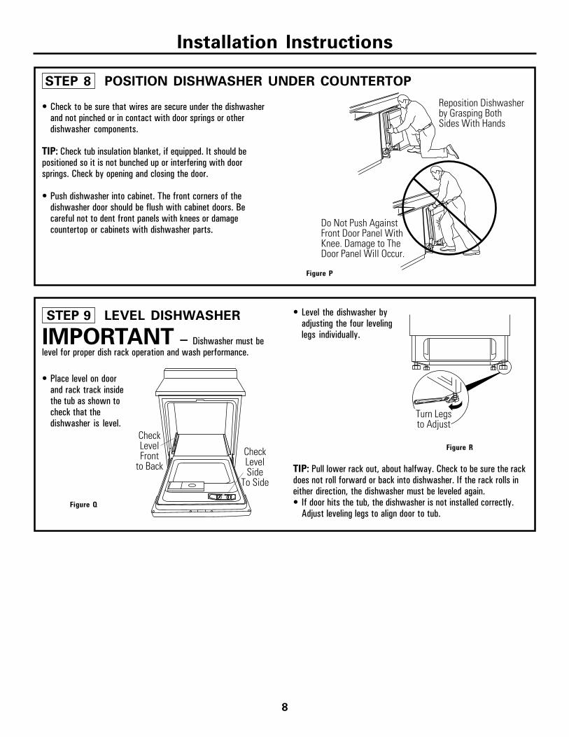
Do Not Push AgainstFront Door Panel With Knee. Damage to The Door Panel Will Occur.
Reposition Dishwasherby Grasping BothSides With Hands
STEP 8 POSITION DISHWASHER UNDER COUNTERTOP
• Check to be sure that wires are secure under the dishwasherand not pinched or in contact with door springs or otherdishwasher components.
TIP: Check tub insulation blanket, if equipped. It should bepositioned so it is not bunched up or interfering with doorsprings. Check by opening and closing the door.
• Push dishwasher into cabinet. The front corners of thedishwasher door should be flush with cabinet doors. Becareful not to dent front panels with knees or damagecountertop or cabinets with dishwasher parts.
Installation Instructions
• Level the dishwasher byadjusting the four levelinglegs individually.
• Place level on doorand rack track insidethe tub as shown tocheck that thedishwasher is level.
CheckLevelSide
To Side
CheckLevelFront
to Back
Turn Legsto Adjust
STEP 9 LEVEL DISHWASHER
IMPORTANT – Dishwasher must belevel for proper dish rack operation and wash performance.
Figure Q
TIP: Pull lower rack out, about halfway. Check to be sure the rackdoes not roll forward or back into dishwasher. If the rack rolls ineither direction, the dishwasher must be leveled again.• If door hits the tub, the dishwasher is not installed correctly.
Adjust leveling legs to align door to tub.
Figure P
Figure R

9
Installation Instructions
The dishwasher must be secured to the countertop.• Position the dishwasher so that the tub flange aligns with the
front face of the cabinet frame.
IMPORTANT: Check to be sure the dishwasher is centered inthe opening and there is no interference with adjacent cabinetswhen opening or closing the door.
STEP 10 SECURE DISHWASHERTO CABINET
IMPORTANT – Drive screwsstraight and flush. Protruding screw heads will scratch the topof the control panel and can interfere with door closing.
STEP 11 CONNECT WATERSUPPLY
• Fasten the dishwasher to the underside of the countertopwith the 2 Phillips screws provided.
Ferrule
90° Elbow
Compression Nut
Hot WaterSupply Line
Figure S IMPORTANT – Check to be sure thatdoor spring does not rub or contact the fill hose or water supplyline. Test by opening and closing the door. Re-route the lines if arubbing noise or interference occurs.
Figure T
Connect water supply to 90° elbow.• Slide compression nut, then ferrule over end of water line.• Insert water line into 90° elbow.• Slide ferrule against elbow and secure with compression nut.
Align TubFlangeto FrontFace ofCabinetFrame

10
Installation Instructions
DRAIN LINE INSTALLATION
• Connect drain line to air gap, waste tee or disposer using eitherpreviously determined method.
Waste Tee Installation Disposer Installation
Method 2 – High drain loop with waste tee or disposer
IMPORTANT –When connecting drain line to disposer,check to be sure that drain plug has beenremoved. DISHWASHER WILL NOT DRAINIF PLUG IS LEFT IN PLACE.TIP: Avoid unnecessary service call charges. Always be suredisposer drain plug has been removed before attaching dishwasherdrain hose to the disposer.
Cutting Lines
1" 3/4" 5/8"
IMPORTANT: Do not cut corrugated portion of hose
Fasten to undersideof countertop
32"Min.18"
Min.
Fasten to undersideof countertop
18"Min.
Hose ClampCoupler
Hose Clamp
RemoveDisposer
Plug
STEP 12 CONNECT DRAIN LINE
FOLLOW ALL LOCAL CODES AND ORDINANCES.
The drain hose molded end will fit 5/8”, 3/4” or 1” diameterconnections on the air gap, waste tee or disposer. Cut on themarked line as required for your installation.
Figure U
Figure V
• If a longer drain hose is required, add up to 42” of length for atotal of 10 ft. to the factory installed hose. Use 5/8” or 7/8”inside diameter hose and a coupler to connect the two hoseends. Secure the connection with hose clamps.
• Secure the drain hose to the air gap, waste tee or disposerwith clamps.
NOTE: TOTAL DRAIN HOSE LENGTH MUST NOT EXCEED10 FEET FOR PROPER DRAIN OPERATION.
Method 1 – Air gap with waste tee or disposer
Figure W
Waste Tee Installation Disposer Installation
Figure X

11
Installation Instructions
STEP 14 PRE-TEST CHECKLISTReview this list after installing your dishwasher toavoid charges for a service call that is not coveredby your warranty.
Check to be sure power is OFF.
Open door and remove all foam and paper packaging.
Locate the Owner’s Manual in the literature package.
Read the Owner’s Manual for operating instructions.
Check door opening and closing. If door does not open andclose freely or tends to fall, check spring adjustments. SeeStep 1.
Check to be sure that wiring is secure under the dishwasher,not pinched or in contact with door springs or othercomponents. See Step 9.
Check door alignment with tub. If door hits tub, leveldishwasher. See Step 10.
Pull lower rack out, about half way. Check to be sure it doesnot roll back or forward on the door. If the rack moves, adjustleveling legs. See Step 10.
Check door alignment with cabinet. If door hits cabinet,reposition or relevel dishwasher. See Step 10.
Verify water supply and drain lines are not kinked or incontact with other components. Contact with motor ordishwasher frame could cause noise. See Step 8.
Turn on the sink hot water faucet and verify watertemperature. Incoming water temperature must be between120°F and 150°F. A minimum of 120°F temperature isrequired for best wash performance. See "Prepare Hot WaterLine", page 5.
Add 2 quarts of water to the bottom of the dishwasher tolubricate the pump seal.
Turn on water supply. Check for leaks. Tighten connectionsif needed.
Remove protective film if present from the control panel anddoor.
STEP 13 CONNECT POWERSUPPLY
Skip this step if equipped with power cord.Verify that power is turned off at the source.
• Remove junction box cover “A”.• Locate the three dishwasher wires, (white, black and green)
with stripped ends. Insert dishwasher wires through thesmall hole in the junction box “B”.
• Secure house wiring to the bottom of the junction box with astrain relief “C”.
• User wire nuts to connect incoming ground to green, white towhite and black to black “D”.
• Replace junction box cover “E”. Check to be sure that wiresare not pinched under the cover.
E. Replace Junction Box Cover
WARNINGIf house wiring is not 2-wire with ground,a ground must be provided by the installer.When house wiring is aluminum, be sure touse UL Listed anti-oxidant compound andaluminum-to-copper connectors.

Installation Instructions
• Place 2-piece toekick against the legs of the dishwasher.• Place the inner toekick piece (with slots) against the toekick
bracket. The slots should align with toekick bracket screwholes. Allow the toekick to touch the floor.
• Place larger toekick over the inner piece and install 4 toekickscrews.
• Use additional 2 screws that are provided for installationsover 33-1/2” high.
• Use both toekick pieces for all installation heights.
Figure Y
STEP 16 REPLACE TOEKICKSTEP 15 DISHWASHER WET TEST
Turn on power supply (or plug power cord into outlet, if equipped).
Turn dial to Normal “Wash” position.
Close door.
Check to be sure that water enters the dishwasher. If water does notenter the dishwasher, check to be sure that water and power areturned on.
Check for leaks under the dishwasher. If a leak is found, turn powersupply off, then tighten connections. Restore power after leak iscorrected.
Check for leaks around the door. A leak around the door could becaused by door rubbing or hitting against adjacent cabinetry. Repositionthe dishwasher if necessary. See Step 9.
The dishwasher will drain and turn off about 5 to 7 minutes after thefirst fill. Check drain lines. If leaks are found, turn power off at thebreaker and correct plumbing as necessary. Restore power aftercorrections are made. See Step 12.
Open dishwasher door and make sure most of the water has drained.If not, check that disposer plug has been removed and/or air gap is notplugged. See Step 13. Also check drain line for kinking.
Run the dishwasher through another fill and drain cycle. Check forleaks and correct if required.
At the end of drain, open door and turn dial to OFF position.
STEP 17 LITERATUREBe sure to leave complete literature package and installationinstructions with consumer.
2-Piece ToekickAdjust Upor Down
Use Top 4Screw Holes