bundaberg regional council east sewerage treatment plant regional sewerage pump ...€¦ · ·...
TRANSCRIPT

Regional Sewerage Pump Station - Design Report
Page 1 of 30
Bundaberg Regional Council
East Sewerage Treatment Plant
Regional Sewerage Pump Station
Design Report
Revision 1
December 2011
Regional Sewerage Pump Station - Design Report
Page II
Document Control
Version Date Author Reviewer
Name Initials Name Initials
1 January 2012 Megan Kraft MK Kane Macready

Regional Sewerage Pump Station - Design Report
Page III
Contents
EXECUTIVE SUMMARY ........................................................................................................................... 1
1 INTRODUCTION ............................................................................................................................ 3
2 SEWERAGE LOAD .......................................................................................................................... 4
3 RISING MAIN DESIGN .................................................................................................................... 6
3.1 ALIGNMENT .......................................................................................................................................................... 6
3.2 SIZE AND MATERIAL ................................................................................................................................................ 6
3.3 CONSTRUCTABILITY ................................................................................................................................................. 9
3.4 DESIGN SPECIFICATION ............................................................................................................................................ 9
4 SEWERAGE PUMP STATION DESIGN ............................................................................................ 10
4.1 SITE AND LAYOUT ................................................................................................................................................. 10
4.2 DESIGN LIFE OF SEWERAGE PUMP STATION COMPONENTS ........................................................................................... 10
4.3 PUMPING SYSTEM ................................................................................................................................................ 11
4.3.1 Submersible Pumps ..................................................................................................................................... 11
4.3.2 Dry Mounted Self Prime Pumps. ................................................................................................................. 12
4.4 INLET MANHOLE .................................................................................................................................................. 12
4.4.1 Size and Layout ........................................................................................................................................... 12
4.5 WET-WELL DESIGN .............................................................................................................................................. 12
4.5.1 Layout ......................................................................................................................................................... 13
4.5.2 Pump Control Volume and Pump Starts ...................................................................................................... 13
4.5.3 Size .............................................................................................................................................................. 14
4.5.4 Control Levels .............................................................................................................................................. 14
4.5.5 Benching ..................................................................................................................................................... 14
4.6 EMERGENCY STORAGE .......................................................................................................................................... 15
4.7 EMERGENCY RELIEF SYSTEM ................................................................................................................................... 16
4.8 POWER SYSTEM ................................................................................................................................................... 16
4.9 CONTROL AND TELEMETRY SYSTEM.......................................................................................................................... 16
4.10 OPERATIONAL ISSUES ............................................................................................................................................ 16
4.10.1 Standby Generator ................................................................................................................................. 16
4.10.2 Standby diesel pump............................................................................................................................... 17
5 ESTIMATE OF COST ..................................................................................................................... 18
6 ODOUR MANAGEMENT .............................................................................................................. 18
7 SAFETY IN DESIGN ...................................................................................................................... 20
8 CONCLUSIONS AND RECOMMENDATIONS ................................................................................... 21
8.1 RISING MAIN....................................................................................................................................................... 21
8.2 SEWERAGE PUMP STATION .................................................................................................................................... 21
8.3 ODOUR CONTROL ................................................................................................................................................ 22
Regional Sewerage Pump Station - Design Report
Page 1 of 22
EXECUTIVE SUMMARY
SITUATION – Bundaberg Regional Council (BRC) has identified the need for a new regional sewerage
treatment plant (STP) to provide for population growth in East Bundaberg and the communities between
Burnett Heads and Elliot Heads. The proposed regional STP will be located in Rubyanna and will replace the
ageing East Sewerage Treatment Plant (ESTP) on Alexandra Street.
It is proposed that existing flows to ESTP will be diverted to the new regional plant at Rubyanna by a
regional pump station located at the ESTP site and associated rising main.
ISSUES – Sewerage flows currently are delivered to the ESTP by a number of pump stations and rising
mains. In order to divert flows from ESTP to the proposed treatment plant at Rubyanna, sewerage will be
required to be diverted from the inlet works of ESTP to the proposed pump station. Note that the pump
station will have to be incorporated with valving that will allow the incoming sewer mains to feed either the
pump station or the old treatment plant during the commissioning process.
It has also been advised that the existing ESTP currently experiences odour issues at the inlet works. As part
of this report an investigation into the available odour treatment systems has been completed and
recommendations made.
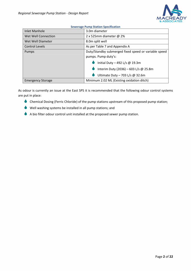
SOLUTION – A preliminary design has been completed as per WSA-04 Sewerage Pumping Station Code for
the rising main and sewerage pump station. The specification for each is detailed in the tables below.
Preliminary drawings for the pump station layout are included in Appendix A and a preliminary long section
of the rising main has been completed (Appendix C). The preliminary estimate of cost for the construction
of the rising main and pump station is $9,545,735 excl GST.
Sewerage Rising Main Specification
Pipe Diameter 600mm
Pipe Material Glass Reinforced Plastic (GRP)
Jointing Mechanism Socket-Spigot
Allowable Joint Deflection As per manufacturers tolerance
Minimum Pipeline Cover 900mm
Alignment from Property Boundary As per preliminary design drawings
Regional Sewerage Pump Station - Design Report
Page 2 of 22
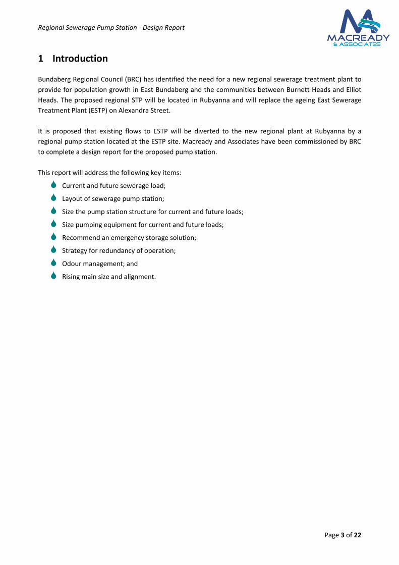
Sewerage Pump Station Specification
Inlet Manhole 3.0m diameter
Wet Well Connection 2 x 525mm diameter @ 2%
Wet Well Diameter 8.0m split well
Control Levels As per Table 7 and Appendix A
Pumps Duty/Standby submerged fixed speed or variable speed
pumps. Pump duty’s:
Initial Duty – 492 L/s @ 19.3m
Interim Duty (2036) – 603 L/s @ 25.8m
Ultimate Duty – 703 L/s @ 32.6m
Emergency Storage Minimum 2.02 ML (Existing oxidation ditch)
As odour is currently an issue at the East SPS it is recommended that the following odour control systems
are put in place:
Chemical Dosing (Ferric Chloride) of the pump stations upstream of this proposed pump station;
Well washing systems be installed in all pump stations; and
A bio filter odour control unit installed at the proposed sewer pump station.
Regional Sewerage Pump Station - Design Report
Page 3 of 22
1 Introduction
Bundaberg Regional Council (BRC) has identified the need for a new regional sewerage treatment plant to
provide for population growth in East Bundaberg and the communities between Burnett Heads and Elliot
Heads. The proposed regional STP will be located in Rubyanna and will replace the ageing East Sewerage
Treatment Plant (ESTP) on Alexandra Street.
It is proposed that existing flows to ESTP will be diverted to the new regional plant at Rubyanna by a
regional pump station located at the ESTP site. Macready and Associates have been commissioned by BRC
to complete a design report for the proposed pump station.
This report will address the following key items:
Current and future sewerage load;
Layout of sewerage pump station;
Size the pump station structure for current and future loads;
Size pumping equipment for current and future loads;
Recommend an emergency storage solution;
Strategy for redundancy of operation;
Odour management; and
Rising main size and alignment.
Regional Sewerage Pump Station - Design Report
Page 4 of 22
2 Sewerage Load
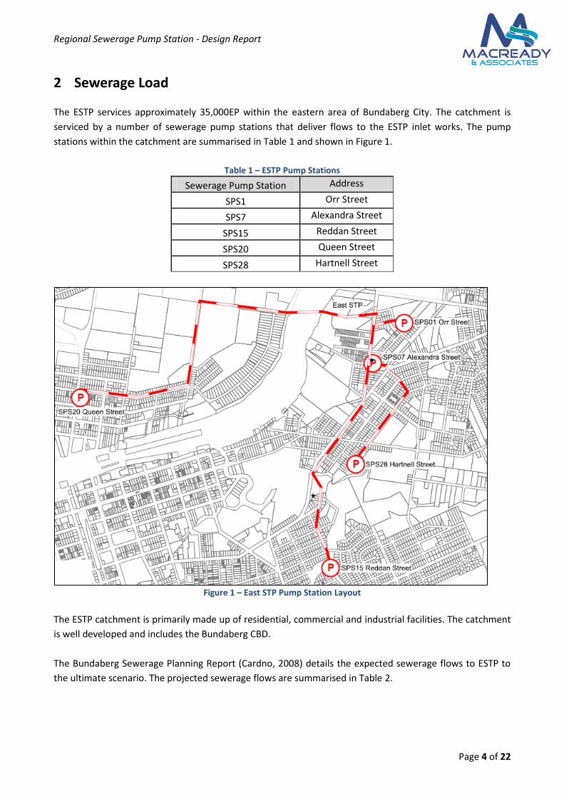
The ESTP services approximately 35,000EP within the eastern area of Bundaberg City. The catchment is
serviced by a number of sewerage pump stations that deliver flows to the ESTP inlet works. The pump
stations within the catchment are summarised in Table 1 and shown in Figure 1.
Table 1 – ESTP Pump Stations
Sewerage Pump Station Address
SPS1 Orr Street
SPS7 Alexandra Street
SPS15 Reddan Street
SPS20 Queen Street
SPS28 Hartnell Street
Figure 1 – East STP Pump Station Layout
The ESTP catchment is primarily made up of residential, commercial and industrial facilities. The catchment
is well developed and includes the Bundaberg CBD.
The Bundaberg Sewerage Planning Report (Cardno, 2008) details the expected sewerage flows to ESTP to
the ultimate scenario. The projected sewerage flows are summarised in Table 2.
Regional Sewerage Pump Station - Design Report
Page 5 of 22
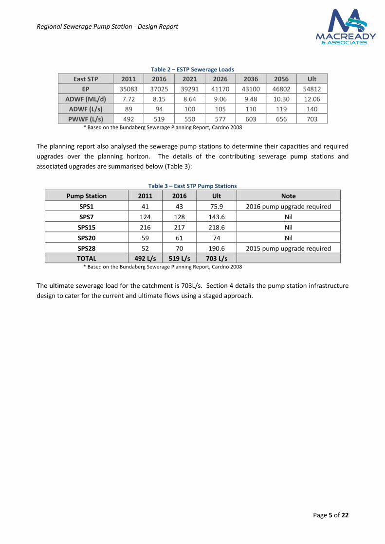
Table 2 – ESTP Sewerage Loads
East STP 2011 2016 2021 2026 2036 2056 Ult
EP 35083 37025 39291 41170 43100 46802 54812
ADWF (ML/d) 7.72 8.15 8.64 9.06 9.48 10.30 12.06
ADWF (L/s) 89 94 100 105 110 119 140
PWWF (L/s) 492 519 550 577 603 656 703 * Based on the Bundaberg Sewerage Planning Report, Cardno 2008
The planning report also analysed the sewerage pump stations to determine their capacities and required
upgrades over the planning horizon. The details of the contributing sewerage pump stations and
associated upgrades are summarised below (Table 3):
Table 3 – East STP Pump Stations
Pump Station 2011 2016 Ult Note
SPS1 41 43 75.9 2016 pump upgrade required
SPS7 124 128 143.6 Nil
SPS15 216 217 218.6 Nil
SPS20 59 61 74 Nil
SPS28 52 70 190.6 2015 pump upgrade required
TOTAL 492 L/s 519 L/s 703 L/s * Based on the Bundaberg Sewerage Planning Report, Cardno 2008
The ultimate sewerage load for the catchment is 703L/s. Section 4 details the pump station infrastructure
design to cater for the current and ultimate flows using a staged approach.
Regional Sewerage Pump Station - Design Report
Page 6 of 22
3 Rising Main Design
3.1 Alignment
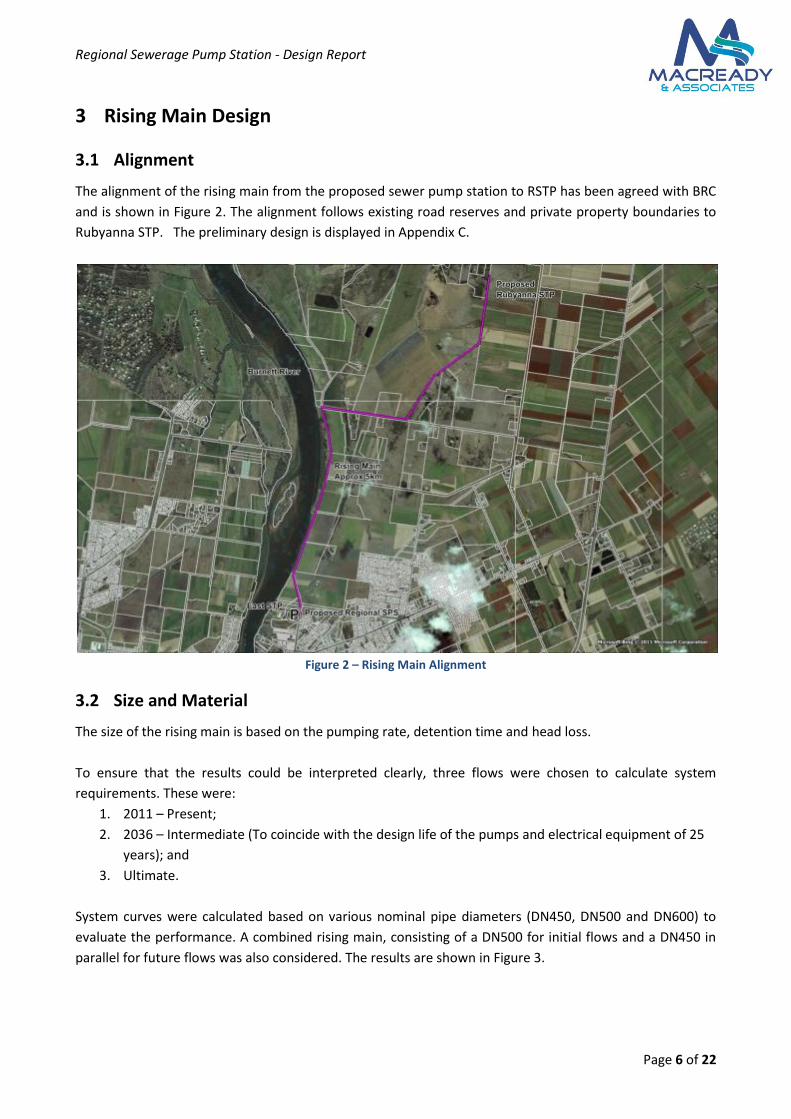
The alignment of the rising main from the proposed sewer pump station to RSTP has been agreed with BRC
and is shown in Figure 2. The alignment follows existing road reserves and private property boundaries to
Rubyanna STP. The preliminary design is displayed in Appendix C.
Figure 2 – Rising Main Alignment
3.2 Size and Material
The size of the rising main is based on the pumping rate, detention time and head loss.
To ensure that the results could be interpreted clearly, three flows were chosen to calculate system
requirements. These were:
1. 2011 – Present;
2. 2036 – Intermediate (To coincide with the design life of the pumps and electrical equipment of 25
years); and
3. Ultimate.
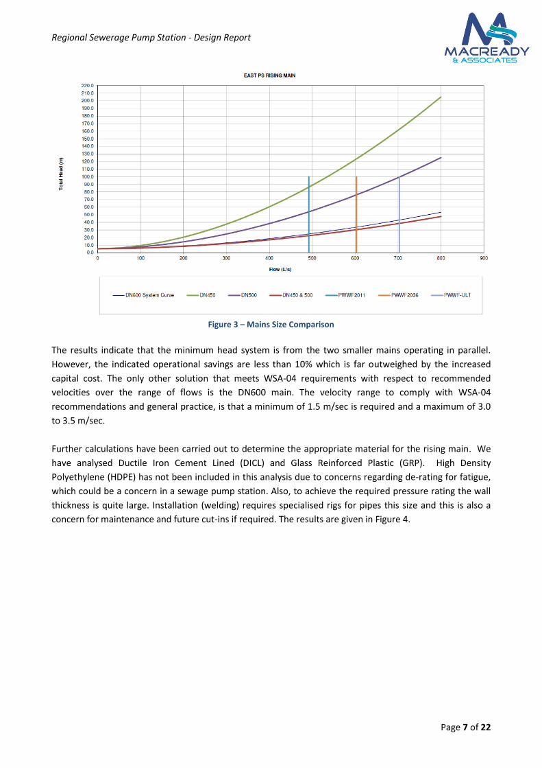
System curves were calculated based on various nominal pipe diameters (DN450, DN500 and DN600) to
evaluate the performance. A combined rising main, consisting of a DN500 for initial flows and a DN450 in
parallel for future flows was also considered. The results are shown in Figure 3.
Regional Sewerage Pump Station - Design Report
Page 7 of 22
Figure 3 – Mains Size Comparison
The results indicate that the minimum head system is from the two smaller mains operating in parallel.
However, the indicated operational savings are less than 10% which is far outweighed by the increased
capital cost. The only other solution that meets WSA-04 requirements with respect to recommended
velocities over the range of flows is the DN600 main. The velocity range to comply with WSA-04
recommendations and general practice, is that a minimum of 1.5 m/sec is required and a maximum of 3.0
to 3.5 m/sec.
Further calculations have been carried out to determine the appropriate material for the rising main. We
have analysed Ductile Iron Cement Lined (DICL) and Glass Reinforced Plastic (GRP). High Density
Polyethylene (HDPE) has not been included in this analysis due to concerns regarding de-rating for fatigue,
which could be a concern in a sewage pump station. Also, to achieve the required pressure rating the wall
thickness is quite large. Installation (welding) requires specialised rigs for pipes this size and this is also a
concern for maintenance and future cut-ins if required. The results are given in Figure 4.

Regional Sewerage Pump Station - Design Report
Page 8 of 22
Figure 4 – Mains Type Comparison
The results indicate that the DN600 GRP pipe is the most economical option in terms of operational costs,
with the DN600 DICL incurring approximately 17% increase and the DN525 GRP incurring approximately
65% increase in operational (power) costs. Based on current ADWF and a power cost of $0.15/KWh, the
annual power costs are around $30,000/year at ADWF flows.
Based on budget costs from suppliers, the GRP is also the lower capital expenditure when compared to the
DICL, making it the preferred pipe material. The capital savings on the DN525 GRP would not be sufficient
to justify the additional operational costs - approximately $300,000 in capital savings against approximately
$487,000 in power costs over 25 years (today’s costs).
The recommended maximum detention time within rising mains is 2 hours (WSA-04). The detention time in
the rising main is 5.3 hours for initial flows and 3.3 hours for the ultimate flows. This is greater than the
recommended times and will lead to consequent septicity in the mains and potential odour concerns, as
well as the potential for corrosion of structures including concrete pipe lining. Given that GRP does not
have a cement lining and is constructed using inert materials then it will fair best under these
circumstances. As the rising main will also be constructed within a marine area GRP will provide greater
resistance to corrosion from external factors.
Air relief valves should be installed on all high points in the mains to minimise the possibility of air
entrainment. Scour valves should also be included on low points in accordance with WSA standard
drawings.
Technical data on glass reinforced pipe is included in Appendix D.
Regional Sewerage Pump Station - Design Report
Page 9 of 22
3.3 Constructability
The alignment of this main is proposed to be predominantly constructed in open space/BRC road reserve
which is expected to result in a relatively straight forward construction phase due to the minimal works
requiring traffic control and the need to provide access to businesses or residents.
BRC have indicated that the proposed Rubyanna STP site is above the 100 year ARI flood level and that no
major earthworks will be required to lift the level of the site. Given this we have designed the rising main
and pump station based on the existing natural surface level.
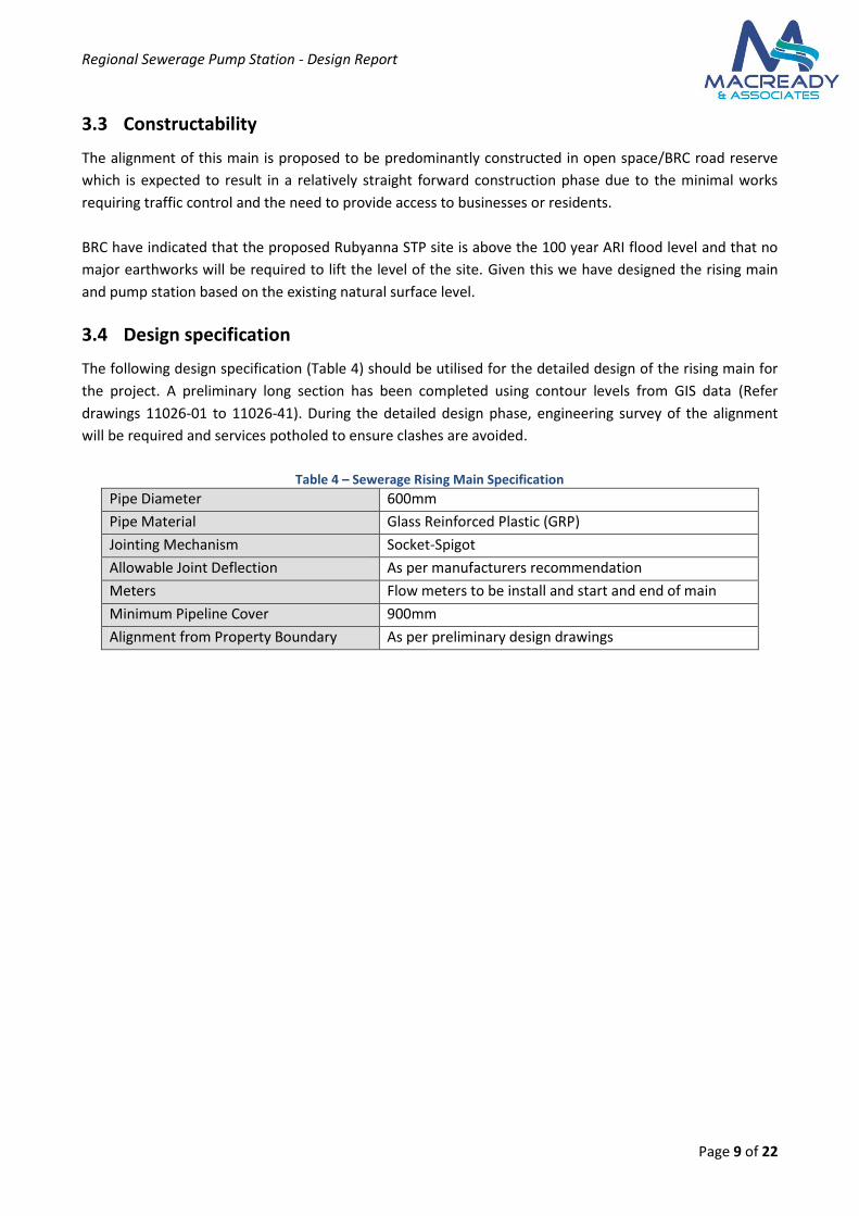
3.4 Design specification
The following design specification (Table 4) should be utilised for the detailed design of the rising main for
the project. A preliminary long section has been completed using contour levels from GIS data (Refer
drawings 11026-01 to 11026-41). During the detailed design phase, engineering survey of the alignment
will be required and services potholed to ensure clashes are avoided.
Table 4 – Sewerage Rising Main Specification
Pipe Diameter 600mm
Pipe Material Glass Reinforced Plastic (GRP)
Jointing Mechanism Socket-Spigot
Allowable Joint Deflection As per manufacturers recommendation
Meters Flow meters to be install and start and end of main
Minimum Pipeline Cover 900mm
Alignment from Property Boundary As per preliminary design drawings
Regional Sewerage Pump Station - Design Report
Page 10 of 22
4 Sewerage Pump Station Design
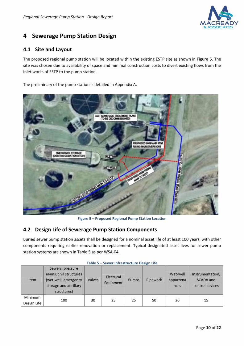
4.1 Site and Layout
The proposed regional pump station will be located within the existing ESTP site as shown in Figure 5. The
site was chosen due to availability of space and minimal construction costs to divert existing flows from the
inlet works of ESTP to the pump station.
The preliminary of the pump station is detailed in Appendix A.
Figure 5 – Proposed Regional Pump Station Location
4.2 Design Life of Sewerage Pump Station Components
Buried sewer pump station assets shall be designed for a nominal asset life of at least 100 years, with other
components requiring earlier renovation or replacement. Typical designated asset lives for sewer pump
station systems are shown in Table 5 as per WSA-04.
Table 5 – Sewer Infrastructure Design Life
Item
Sewers, pressure
mains, civil structures
(wet-well, emergency
storage and ancillary
structures)
Valves Electrical
Equipment Pumps Pipework
Wet-well
appurtena
nces
Instrumentation,
SCADA and
control devices
Minimum
Design Life 100 30 25 25 50 20 15
Regional Sewerage Pump Station - Design Report
Page 11 of 22
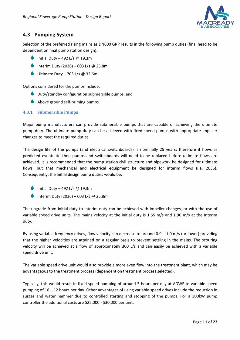
4.3 Pumping System
Selection of the preferred rising mains as DN600 GRP results in the following pump duties (final head to be
dependent on final pump station design):
Initial Duty – 492 L/s @ 19.3m
Interim Duty (2036) – 603 L/s @ 25.8m
Ultimate Duty – 703 L/s @ 32.6m
Options considered for the pumps include:
Duty/standby configuration submersible pumps; and
Above ground self-priming pumps.
4.3.1 Submersible Pumps
Major pump manufacturers can provide submersible pumps that are capable of achieving the ultimate
pump duty. The ultimate pump duty can be achieved with fixed speed pumps with appropriate impeller
changes to meet the required duties.
The design life of the pumps (and electrical switchboards) is nominally 25 years; therefore if flows as
predicted eventuate then pumps and switchboards will need to be replaced before ultimate flows are
achieved. It is recommended that the pump station civil structure and pipework be designed for ultimate
flows, but that mechanical and electrical equipment be designed for interim flows (i.e. 2036).
Consequently, the initial design pump duties would be:
Initial Duty – 492 L/s @ 19.3m
Interim Duty (2036) – 603 L/s @ 25.8m
The upgrade from initial duty to interim duty can be achieved with impeller changes, or with the use of
variable speed drive units. The mains velocity at the initial duty is 1.55 m/s and 1.90 m/s at the Interim
duty.
By using variable frequency drives, flow velocity can decrease to around 0.9 – 1.0 m/s (or lower) providing
that the higher velocities are attained on a regular basis to prevent settling in the mains. The scouring
velocity will be achieved at a flow of approximately 300 L/s and can easily be achieved with a variable
speed drive unit.
The variable speed drive unit would also provide a more even flow into the treatment plant, which may be
advantageous to the treatment process (dependent on treatment process selected).
Typically, this would result in fixed speed pumping of around 5 hours per day at ADWF to variable speed
pumping of 10 – 12 hours per day. Other advantages of using variable speed drives include the reduction in
surges and water hammer due to controlled starting and stopping of the pumps. For a 300kW pump
controller the additional costs are $25,000 - $30,000 per unit.
Regional Sewerage Pump Station - Design Report
Page 12 of 22
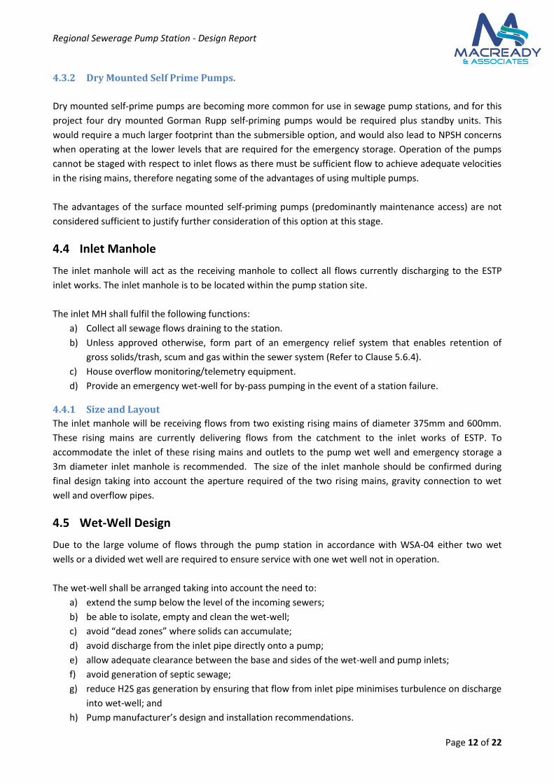
4.3.2 Dry Mounted Self Prime Pumps.
Dry mounted self-prime pumps are becoming more common for use in sewage pump stations, and for this
project four dry mounted Gorman Rupp self-priming pumps would be required plus standby units. This
would require a much larger footprint than the submersible option, and would also lead to NPSH concerns
when operating at the lower levels that are required for the emergency storage. Operation of the pumps
cannot be staged with respect to inlet flows as there must be sufficient flow to achieve adequate velocities
in the rising mains, therefore negating some of the advantages of using multiple pumps.
The advantages of the surface mounted self-priming pumps (predominantly maintenance access) are not
considered sufficient to justify further consideration of this option at this stage.
4.4 Inlet Manhole
The inlet manhole will act as the receiving manhole to collect all flows currently discharging to the ESTP
inlet works. The inlet manhole is to be located within the pump station site.
The inlet MH shall fulfil the following functions:
a) Collect all sewage flows draining to the station.
b) Unless approved otherwise, form part of an emergency relief system that enables retention of
gross solids/trash, scum and gas within the sewer system (Refer to Clause 5.6.4).
c) House overflow monitoring/telemetry equipment.
d) Provide an emergency wet-well for by-pass pumping in the event of a station failure.
4.4.1 Size and Layout
The inlet manhole will be receiving flows from two existing rising mains of diameter 375mm and 600mm.
These rising mains are currently delivering flows from the catchment to the inlet works of ESTP. To
accommodate the inlet of these rising mains and outlets to the pump wet well and emergency storage a
3m diameter inlet manhole is recommended. The size of the inlet manhole should be confirmed during
final design taking into account the aperture required of the two rising mains, gravity connection to wet
well and overflow pipes.
4.5 Wet-Well Design
Due to the large volume of flows through the pump station in accordance with WSA-04 either two wet
wells or a divided wet well are required to ensure service with one wet well not in operation.
The wet-well shall be arranged taking into account the need to:
a) extend the sump below the level of the incoming sewers;
b) be able to isolate, empty and clean the wet-well;
c) avoid “dead zones” where solids can accumulate;
d) avoid discharge from the inlet pipe directly onto a pump;
e) allow adequate clearance between the base and sides of the wet-well and pump inlets;
f) avoid generation of septic sewage;
g) reduce H2S gas generation by ensuring that flow from inlet pipe minimises turbulence on discharge
into wet-well; and
h) Pump manufacturer’s design and installation recommendations.
Regional Sewerage Pump Station - Design Report
Page 13 of 22
The design shall incorporate either a drop pipe from the inlet isolating valve at the end of a horizontal inlet
pipe or a steeply-sloped inlet pipe with an isolating valve in the wet-well. In either case, the inlet pipe shall
end at least one pipe diameter above the normal pump cut-out level to allow the inlet pipe to drain
completely on every pump cycle.
The depth of the wet-well shall be determined having regard to:
i. sewer invert;
ii. cut-in/cut-out volume;
iii. minimum pump submergence; and
iv. minimum depth below the pump intake specified by the pump manufacturer.
4.5.1 Layout
For large pump stations WSA-04 specifies that either two separate wet wells or a split wet well is required.
For the proposed pump station it is recommended that a split well is constructed. A split well has the
following advantages:
Reduced construction costs; and
Ability to shut down one side of well for maintenance or if pumps fail.
Within the split well a connection between the two compartments will be required with a valve to enable
isolation.
Flows from the inlet manhole to the pump well will be via two gravity mains entering the two
compartments of the wet well; each of these mains shall have an isolation valve located within the inlet
manhole to enable isolation of either compartment of the wet well. Appendix A shows the proposed layout
of the wet well and connection to the inlet manhole.
4.5.2 Pump Control Volume and Pump Starts
The pump control volume is based on the following calculation:
Where
Vww is the pump control volume (cut-in / cut-out volume)
Qp is the pumping rate
Smax is the maximum allowable number of pump starts per hour
This volume ensures that for any ratio of dry weather inflow to the wet well and pumping rate the
maximum allowable number of starts is not exceeded.
The maximum allowable number of pump starts per hour shall be 8 or 90% of manufacturer’s
recommended number, whichever is lower, subject to power supply and equipment limitations.
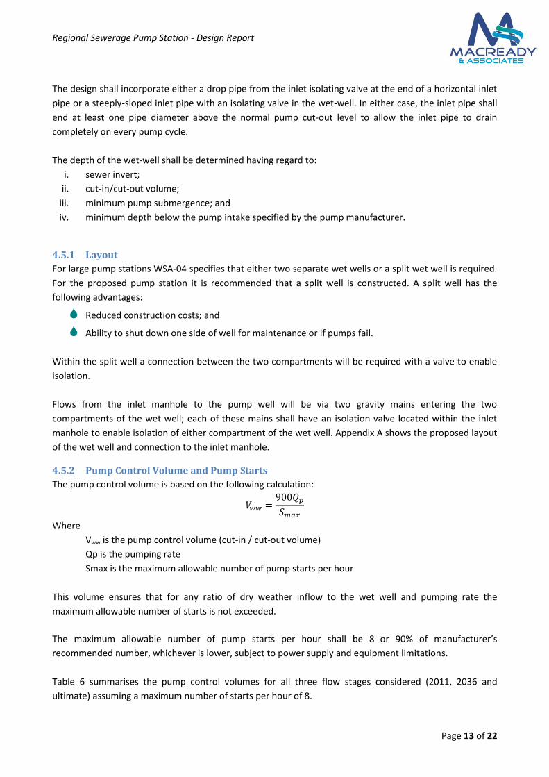
Table 6 summarises the pump control volumes for all three flow stages considered (2011, 2036 and
ultimate) assuming a maximum number of starts per hour of 8.
Regional Sewerage Pump Station - Design Report
Page 14 of 22
Table 6 – Pump Control Volume
Year Flow (L/s) Vww (kL)
2011 492 55.4
2036 603 67.85
Ultimate 703 79.1
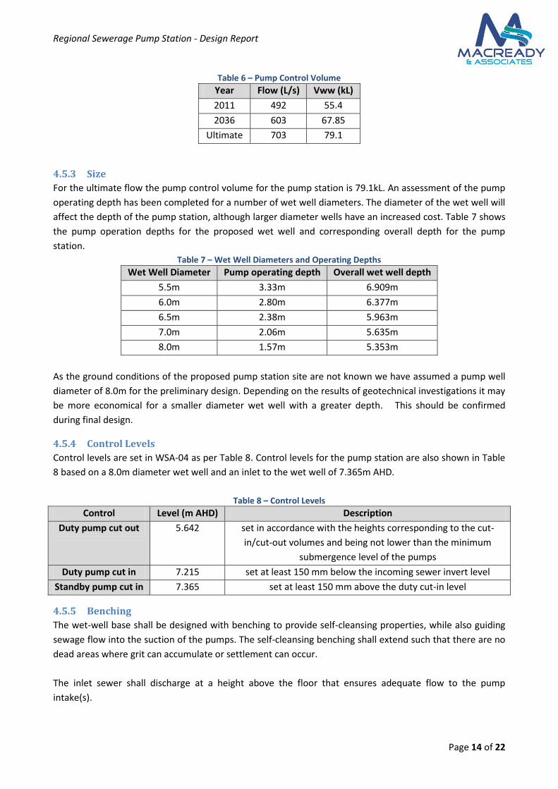
4.5.3 Size
For the ultimate flow the pump control volume for the pump station is 79.1kL. An assessment of the pump
operating depth has been completed for a number of wet well diameters. The diameter of the wet well will
affect the depth of the pump station, although larger diameter wells have an increased cost. Table 7 shows
the pump operation depths for the proposed wet well and corresponding overall depth for the pump
station.
Table 7 – Wet Well Diameters and Operating Depths
Wet Well Diameter Pump operating depth Overall wet well depth
5.5m 3.33m 6.909m
6.0m 2.80m 6.377m
6.5m 2.38m 5.963m
7.0m 2.06m 5.635m
8.0m 1.57m 5.353m
As the ground conditions of the proposed pump station site are not known we have assumed a pump well
diameter of 8.0m for the preliminary design. Depending on the results of geotechnical investigations it may
be more economical for a smaller diameter wet well with a greater depth. This should be confirmed
during final design.
4.5.4 Control Levels
Control levels are set in WSA-04 as per Table 8. Control levels for the pump station are also shown in Table
8 based on a 8.0m diameter wet well and an inlet to the wet well of 7.365m AHD.
Table 8 – Control Levels
Control Level (m AHD) Description
Duty pump cut out 5.642 set in accordance with the heights corresponding to the cut-
in/cut-out volumes and being not lower than the minimum
submergence level of the pumps
Duty pump cut in 7.215 set at least 150 mm below the incoming sewer invert level
Standby pump cut in 7.365 set at least 150 mm above the duty cut-in level
4.5.5 Benching
The wet-well base shall be designed with benching to provide self-cleansing properties, while also guiding
sewage flow into the suction of the pumps. The self-cleansing benching shall extend such that there are no
dead areas where grit can accumulate or settlement can occur.
The inlet sewer shall discharge at a height above the floor that ensures adequate flow to the pump
intake(s).
Regional Sewerage Pump Station - Design Report
Page 15 of 22
4.6 Emergency Storage
Emergency storage will be provided in order to provide adequate time for operations and maintenance, as
well as catering for flows greater than the design capacity of the sewerage pump station (subject to license
conditions). The volume of storage required to be provided is equal to four hours of ADWF, for the
ultimate case the required emergency storage is 2.02 ML.
Within the existing ESTP there is an oxidation tank located adjacent to the proposed SPS site. BRC have
indicated they would like to utilise this tank as emergency storage for the pump station. The existing
oxidation tank is currently uncovered, for effective management of stormwater a roof should be installed
over the structure.
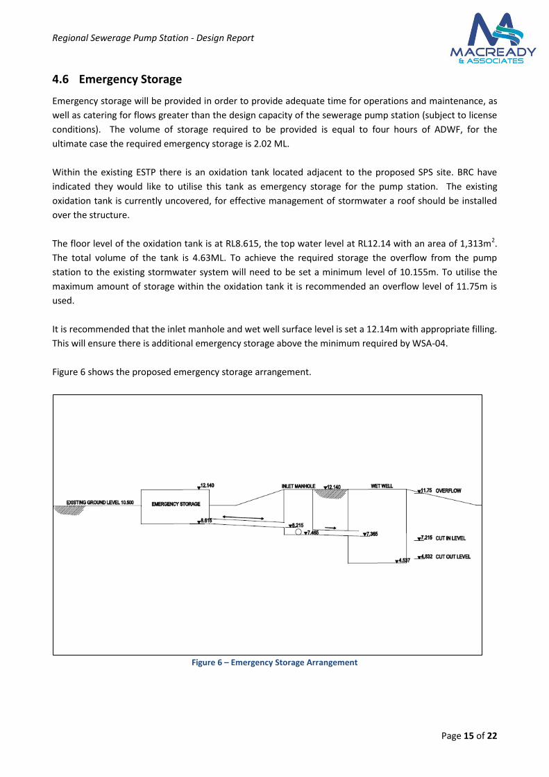
The floor level of the oxidation tank is at RL8.615, the top water level at RL12.14 with an area of 1,313m2.
The total volume of the tank is 4.63ML. To achieve the required storage the overflow from the pump
station to the existing stormwater system will need to be set a minimum level of 10.155m. To utilise the
maximum amount of storage within the oxidation tank it is recommended an overflow level of 11.75m is
used.
It is recommended that the inlet manhole and wet well surface level is set a 12.14m with appropriate filling.
This will ensure there is additional emergency storage above the minimum required by WSA-04.
Figure 6 shows the proposed emergency storage arrangement.
Figure 6 – Emergency Storage Arrangement
Regional Sewerage Pump Station - Design Report
Page 16 of 22
4.7 Emergency Relief System
Pumping stations require an emergency relief system (ERS) to be provided from the inlet manhole or
emergency storage. The ERS can discharge to the following systems (in order of preference):
An adjacent sewer catchment.
A formed stormwater drain e.g. pipe, channel etc.
An unformed drain, creek or watercourse.
A harbour or river.
Tidal waters
The closest available outlet is the existing outfall from ESTP into the Burnett River. The location of the
emergency relief overflow is to be confirmed during final design.
4.8 Power System
As the proposed site is an existing sewerage treatment plant it is assumed that there will be adequate
power supply infrastructure to the site. As the pump station will be required to be operational for a period
of time whilst the ESTP is still operational there may be some need to upgrade the internal power supply
infrastructure. A temporary power connection may also be required during commissioning of the pump
station.
4.9 Control and Telemetry System
All control systems shall be compatible with existing systems, terminology and processes used by BRC.
These shall include but not be limited to:
a) Pumping control;
b) Alarms; and
c) Telemetry system.
The telemetry system shall be capable of connection to BRC’s existing telemetering system.
4.10 Operational Issues
The pump station is designed with duty & standby pumps. An additional spare pump could be kept in the
store to ensure that during pump maintenance (where pump removal is required) that 100% standby
capacity is available at all times. This requirement is not as relevant where the emergency provision is a
standby diesel pump.
4.10.1 Standby Generator
For an ultimate single pump sizing of 310kW starting with a variable speed a 400-500 kVA (to be confirmed
during final design) generator set would be required to supply power to the pumps during power outages.
Should operation with both pumps in parallel be required a generator set of around 800kVA would be
required. The switchboard should be designed with an Automatic Transfer Switch (ATS) for automatic
operation.
Regional Sewerage Pump Station - Design Report
Page 17 of 22
4.10.2 Standby diesel pump
A standby diesel pump can be installed, capable of the ultimate PWWF at maximum speed. Speed would be
limited initially to match the current or interim flows. The diesel pump would provide the following
advantages;
No switchboard so can be used for switchboard outages as well as power outages.
Speed can be varied to suit flows.
Diesel sizing does not have to take into consideration motor starting currents (not relevant when
VSD used).
Switchboard could have ATS installed so that diesel generating set can be readily installed if
required, although this would be unlikely.
Regional Sewerage Pump Station - Design Report
Page 18 of 22
5 Estimate of Cost
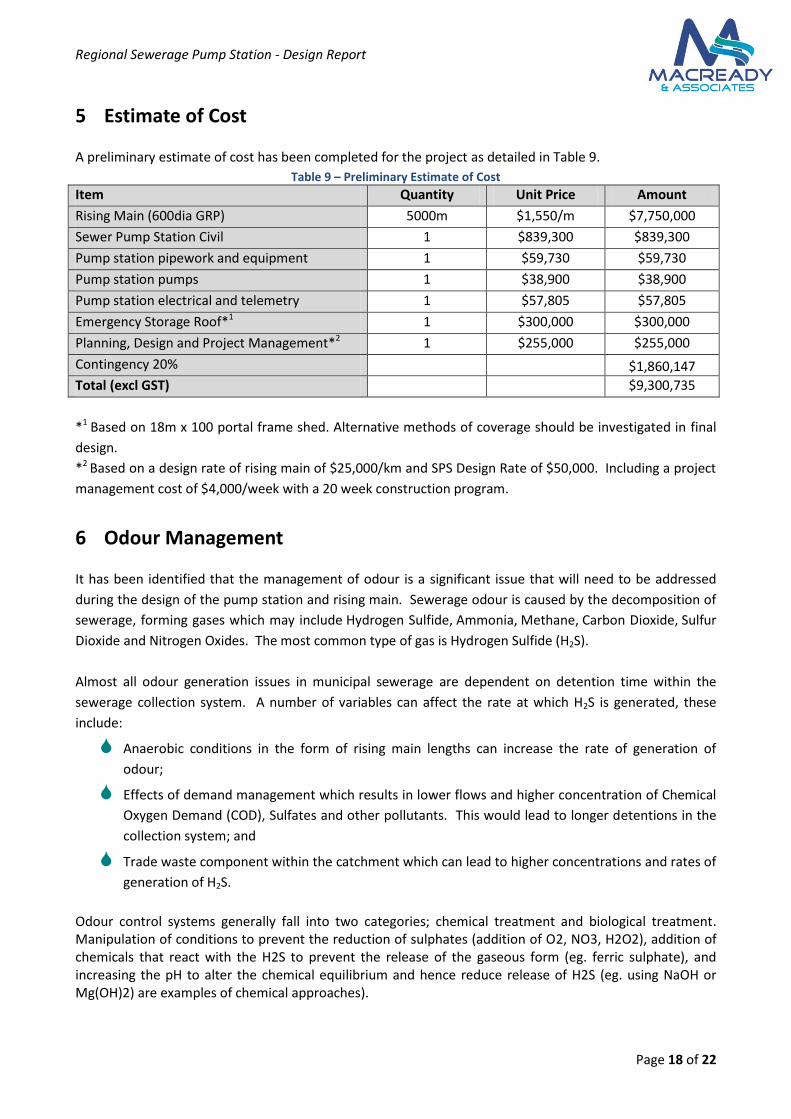
A preliminary estimate of cost has been completed for the project as detailed in Table 9.
Table 9 – Preliminary Estimate of Cost
Item Quantity Unit Price Amount
Rising Main (600dia GRP) 5000m $1,550/m $7,750,000
Sewer Pump Station Civil 1 $839,300 $839,300
Pump station pipework and equipment 1 $59,730 $59,730
Pump station pumps 1 $38,900 $38,900
Pump station electrical and telemetry 1 $57,805 $57,805
Emergency Storage Roof*1 1 $300,000 $300,000
Planning, Design and Project Management*2 1 $255,000 $255,000
Contingency 20% $1,860,147
Total (excl GST) $9,300,735
*1 Based on 18m x 100 portal frame shed. Alternative methods of coverage should be investigated in final
design.
*2 Based on a design rate of rising main of $25,000/km and SPS Design Rate of $50,000. Including a project
management cost of $4,000/week with a 20 week construction program.
6 Odour Management
It has been identified that the management of odour is a significant issue that will need to be addressed
during the design of the pump station and rising main. Sewerage odour is caused by the decomposition of
sewerage, forming gases which may include Hydrogen Sulfide, Ammonia, Methane, Carbon Dioxide, Sulfur
Dioxide and Nitrogen Oxides. The most common type of gas is Hydrogen Sulfide (H2S).
Almost all odour generation issues in municipal sewerage are dependent on detention time within the
sewerage collection system. A number of variables can affect the rate at which H2S is generated, these
include:
Anaerobic conditions in the form of rising main lengths can increase the rate of generation of
odour;
Effects of demand management which results in lower flows and higher concentration of Chemical
Oxygen Demand (COD), Sulfates and other pollutants. This would lead to longer detentions in the
collection system; and
Trade waste component within the catchment which can lead to higher concentrations and rates of
generation of H2S.
Odour control systems generally fall into two categories; chemical treatment and biological treatment. Manipulation of conditions to prevent the reduction of sulphates (addition of O2, NO3, H2O2), addition of chemicals that react with the H2S to prevent the release of the gaseous form (eg. ferric sulphate), and increasing the pH to alter the chemical equilibrium and hence reduce release of H2S (eg. using NaOH or Mg(OH)2) are examples of chemical approaches).

Regional Sewerage Pump Station - Design Report
Page 19 of 22
Biological treatment includes addition of selected strains of bacteria, addition of nutrients to promote growth of certain bacteria, and the removal of biofilms from the pipe walls which contain the sulphate reducing bacteria. It is common practice within the reticulation system to favour chemical treatment.
Historical records have indicated a number of odour complaints in the area surround ESTP and has been
identified by BRC to be an issue that needs to be addressed.
WSA-04 has identified a number of management techniques that can be implemented in the design phase,
these include:
Installation of benching to ensure free flowing of sewerage in the well and no dead areas where
solids can accumulate;
Installation of wet well washers to reduce the frequency of wet well cleaning and the formation of
H2S. These wet well washers should be connected to the water reticulation system with a
disinfectant that will reduce bacterial activity and put H2S back into solution;
Rising main design to minimise detention time to be less than 2hours;
Installation of educt and induct ventilation as per standard drawings SEW 1407 and 1408, is some
cases mechanical means of educt and induct may reduce the hazard of toxic gases. In this case,
mechanical means can be retrofitted to any existing ventilation system.
As odour issues are already being experienced at the inlet of ESTP then it is inherent that the proposed
sewerage pump station and 5km rising main will produce more odour at the inlet of Rubyanna STP.
The recommended maximum detention time within rising mains is 2 hours (WSA-04). The detention time in
the rising main is 5.3 hours for initial flows and 3.3 hours for the ultimate flows. This is greater than the
recommended times and will lead to consequent septicity in the mains and potential odour concerns at the
treatment plant inlet works. This is also discounting any effect in the mains leading into this pump station.
Based on this it is recommend that the following odour control systems are installed:
Chemical Dosing of the pump stations upstream of this proposed pump station. Ferric Chloride is
currently used in the existing pump station within the catchment.
Well washing systems be installed in all pump stations.
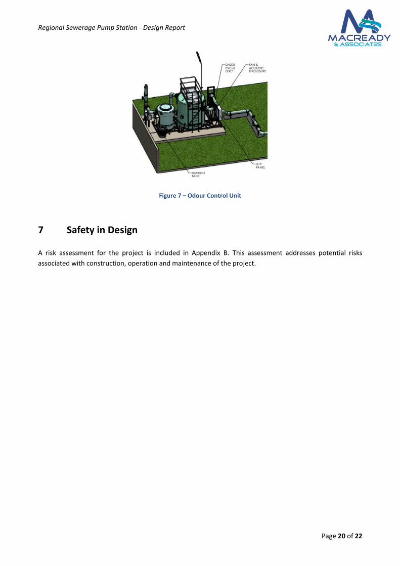
Because chemical dosing does not remove all odour producing components an odour control unit
should be installed at the new pump station. A bio filter odour control unit would remove the
majority of odour causing compounds, and generally requires less maintenance than an activated
carbon filter. As this is currently an industrial area this may provide sufficient control. In a more
intensive residential area a final activated carbon scrubber unit may be required. A typical odour
control unit detail is shown in Figure 7.
Regional Sewerage Pump Station - Design Report
Page 20 of 22
Figure 7 – Odour Control Unit
7 Safety in Design
A risk assessment for the project is included in Appendix B. This assessment addresses potential risks
associated with construction, operation and maintenance of the project.
Regional Sewerage Pump Station - Design Report
Page 21 of 22
8 Conclusions and Recommendations
This report details the preliminary design of a proposed regional pump station at ESTP and rising main. The
proposed pump station will divert flows from the existing sewerage treatment plant to the proposed plant
at Rubyanna. The proposed sewerage pump station will ultimately receive flows of 703L/s.
The preliminary estimate of cost for the construction of the rising main and pump station is $9,545,735 excl
GST.
8.1 Rising Main
A 600mm diameter GRP rising main shall transport flows from the proposed pump station to the new
Rubyanna STP. Table 10 below details the specification for the proposed rising main. The rising main
alignment shall follow exiting road reserves and property boundaries from ESTP to Rubyanna STP and the
alignment is shown in Figure 2.
A preliminary long section has been completed using contour levels from GIS data (Appendix C). During the
detailed design phase, an engineering survey of the alignment will be required.
Table 10 – Sewerage Rising Main Specification
Pipe Diameter 600mm
Pipe Material Glass Reinforced Plastic (GRP)
Jointing Mechanism Socket-Spigot
Allowable Joint Deflection As per manufacturers recommendations
Minimum Pipeline Cover 900mm
Alignment from Property Boundary As per preliminary design drawings
8.2 Sewerage Pump Station
Preliminary design of the proposed sewerage pump station has been completed (Appendix A). Table 11
specifies the preliminary design parameters for the pump station. Preliminary design has been completed
in accordance with WSA-04 Sewerage Pump Station Code.
Table 11 – Sewerage Pump Station Preliminary Design Specification
Inlet Manhole 3.0m diameter
Wet Well Connection 2 x 525mm diameter @ 2%
Wet Well Diameter 8.0m split well
Control Levels As per Table 7 and Appendix A
Pumps Duty/Standby submerged fixed speed or variable speed
pumps. Pump duty’s:
Initial Duty – 492 L/s @ 19.3m
Interim Duty (2036) – 603 L/s @ 25.8m
Ultimate Duty – 703 L/s @ 32.6m
Emergency Storage Minimum 2.02 ML (Existing oxidation ditch)
Regional Sewerage Pump Station - Design Report
Page 22 of 22
8.3 Odour Control
As odour is currently an issue at the East SPS it is recommended that the following odour control systems
are put in place:
Chemical Dosing (Ferric Chloride) of the pump stations upstream of this proposed pump station;
Well washing systems be installed in all pump stations; and
A bio filter odour control unit installed at the proposed sewer pump station.

Regional Sewerage Pump Station - Design Report
Appendix A PRELIMINARY PUMP STATION DESIGN DRAWING

Regional Sewerage Pump Station - Design Report
Appendix B Safety in Design

Regional Sewerage Pump Station - Design Report
Risk matrix
Likelihood Severity
High
Fatality
Major illness
Long term disability
Medium
Injury/illness
Short term disability
Low
Minor injury/illness
High
Certain/nearly certain
H H M
Medium
Reasonably likely
H M L
Low
seldom
M L L
Project: BRC East Sewer Pump Station Design Stage: Preliminary Design
Version: 1 Date: 1/12/11 File: 10014
Phase Considerations Potential Hazards Risk Rating Mitigation options Action
L S R
Design for safe construction Open trench left overnight during
construction
Pedestrian trips and falls
Vehicle drives into trench
L M L Ensure trench is barricaded when Contractor not on site Specification and management of contract works
Materials stored on site become
unsecured
Climbing onto pipe and becoming
loose
Kids playing in sand and collapsing
L H M Ensure all materials are either stored off site or secure fencing
provided
Specification and management of contract works
Connecting into live sewer Infectious disease M M M Ensure all live connection is undertaken by Bundaberg Regional
Council or under their direction
Ensure inoculation
Ensure only qualified Plumbers and Drain Layers work on site
Damage to other services
Electrocution
L
H
M
Contractor to contact service authority to confirm and locate
underground services in vicinity of construction.
Consultation with service authorities to occur prior to construction.
DBYD service to be used. All services to be potholed prior to
construction.
Safe detour routes (Main St & Esplanade
closure)
Injury from vehicle conflict on detour
route.
L M L Traffic management according to MUTCD Considered further during construction
Tree root system damaged during
construction
Tree dies, falls onto road or verge
injuring driver or pedestrian
L H M Ensure vegetation protection works is provided at identified
locations.
Sewer alignment to minimise impact of root system.
Specification and management of contract works to ensure
vegetation protection works is implemented
Trench collapses during excavation
>6.5m
Construction worker buried alive L H M Ensure qualified contractor is employed and contract
specifications adhered to
Specification and management of contract works
Design to facilitate safe use Sewer manhole protrudes above ground
level
Pedestrian trips and falls L L L Ensure manhole is clearly visible
Ensure sewer manhole is set in the correct height in relation to
surrounding ground levels
Specification and management of contract works to ensure good
transition from ground to sewer manhole
Trench slumps Pedestrian trips and falls L L L Ensure trench is adequately compacted when backfilled Specification and management of contract works to ensure good
transition from ground to sewer manhole
Design for safe maintenance
Sewer manholes (all locations) Hurts back when removing manhole
lid
M M M Correct lifting posture, use manhole lifter All works on public sewer to be undertaken by
Bundaberg Regional Council
Falling in the manhole L M L Work in pairs All works on public sewer to be undertaken by
Bundaberg Regional Council
Service person hit by vehicle in
through traffic lane
L H M Final design to review location of manholes to
determine if any can be located in parking lanes or
verges.
Close off through lanes – MUTCD
Close off through lanes – MUTCD

Regional Sewerage Pump Station - Design Report
Appendix C PRELIMINARY RISING MAIN DESIGN DRAWINGS
Regional Sewerage Pump Station - Design Report
Page 5 of 2
Appendix D Promains GRP Specification