bureau of sfcandarab - nist pagewasundertakenwiththeassistanceofthecentralhous-...
TRANSCRIPT

Bureau of Sfcandarab
Lain •i'9.'.ig4q

The program of research on building materials and structures, carried on by the
National Bureau of Standards, was undertaken with the assistance of the Central Hous-ing Committee, an informal organization of governmental agencies concerned with
housing construction and finance, which is cooperating in the investigations through a
committee of principal technicians.
CENTRAL HOUSING COMMITTEEON RESEARCH, DESIGN, AND CONSTRUCTION
A. C. Shire, Chairman. Howard P. Vermilya, Vice Chairman.
United States Housing Authority. Federal Housing Administration.
Sterling R. March, Secretary.
Pierre Blouke,Federal Home Loan Bank Board.
Hugh L. Dryden,National Bureau of Standards.
Louis A. Simon,
Public Buildings Administration.
Luther M. Leisenring,
Construction Division (War).
Edward A. Poynton,Office of Indian Affairs.
John S. Donovan,Farm Security Administration.
George W. Trayer,Forest Service (F. P. Laboratory).
Joseph M. DallaValle,Public Health Service.
George E. Knox,Yards and Docks (Navy).
William R. Talbott,
Veterans' Administration.
Wallace Ashby,
Bureau of Agricultural Chemistry and Engineering.
NATIONAL BUREAU OF STANDARDSSTAFF COMMITTEE ON ADMINISTRATION AND COORDINATION
Hugh L. Dryden, Chairman.
Mechanics and Sound.
Phaon H. Bates, Gustav E. F. Lundell,
Clay and Silicate Products. Chemistry.
HoBART C. Dickinson, Addams S. McAllister,
Heat and Power. Codes and Specifications.
Warren E. Emley, Henry S. Rawdon,Organic and Fibrous Materials. Metallurgy.
The Forest Products Laboratory of the Forest Service is cooperating with both
committees on investigations of wood constructions.
[For list of BMS publications and directions for purchasing, see cover page III.]

UNITED STATES DEPARTMENT OK COMMERCE Jesse H. Jones, Secretary
NATIONAL BUREAU OF STANDARDS • Lyman J. Briggs, Director
BUILDING MATERIALSand STRUCTURES
REPORT BMS66
Plumbing Manual
Report of Subcommittee on Plumbing
Central Housing Committee on Research, Design,
and Construction
ISSUED NOVEMBER 22, 1940
The National Bureau of Standards is a fact-finding organization;
it does not "approve" any particular material or method of con-
struction. The technical findings in this series of reports are to
be construed accordmgly.
UNITED
FOR SALE
STATES GOVERNMENT PRINTING OFFICE • WASHINGTON • I94O
BY THE SUPERINTENDENT OF DOCUMENTS, WASHINGTON, D. C. • PRICE 20 CENTS

ForewordThis report has been prepared by a representative committee to
serve as a guide for Federal agencies that design, install, or approve
plumbing. It is the product of a careful review of existing recom-
mendations, supplemented by consideration of the results of experi-
mental work at this Bureau and by group discussion among the com-
mittee members. The aim has been to insure adequate and healthful
plumbing at a minimum of expense. It is hoped that the report will
prove useful, not only for Federal plumbing work, but also in con-
nection with efforts to bring about greater uniformity in plumbing
requirements and to reduce the cost of construction, of which plumbing
forms a part.
Lyman J. Briggs, Director.
iiii

Plumbing Manual
Report of Subcommittee on Plumbing of the Central Housing Committee on Research,Design, and Construction
Robert K. Thulman, Chairman. ' Vincent T. Manas, Vice Chairman.
Federal Housing AdministTation. United States Housiuo- Authority.
Sterling R. March, Secretary.
Mary Fidelia Taylor, Assistant Secretary.
Roy B. Hunter, Technical Advisor to Subcommittee
National Bureau of Standards.
Charles N. Diener,
Home Owners' Loan Corporation.
Peter J. Furlong,Public Buildings Administration.
Arthur R. Geiger,
Office of Quartermaster General (War).
Norman C. Hepburn,Veterans' Administration.
Robert J. Potbury,
Yards and Docks (Navy), represented byPreston H. Barnard.
John W. Rockey,Bureau of Agricultxu-al Chemistry and Engi-
neering (Agiiculture)
.
Ralph E. Tarbett,
Public Health Service.
George N. Thompson,National Bureau of vStandards.
ABSTRACT
A manual of recommended plumbing practice is pre-
sented by a committee composed of representatives of
Federal agencies most concerned with the subject. Thecommittee has taken into consideration available rec-
ommendations of other bodies and results of research
performed at the National Bureau of Standards.
Part I consists of an introduction explaining the origin
of the work. Part II contains recommendations re-
garding necessary sizes of piping, precautions against
pollution of water supply, permissible types of venting,
and other matters customarily covered in plumbingcodes. Part III contains information useful in apply-
ing the recommendations, including illustrative inter-
pretations of the specific requirements in part II. Therecommendations are presented as suitable for adoption
by Federal agencies engaged in actual plumbing workor in passing upon plans of structures containing plumb-ing.
CONTENTSPage
Foreword ii
I. Introduction 4
II. Recommended minimum requirements for
plumbing 6
Chapter I. Definitions 6
Sec. 101. Definitions 6
Chapter II. General regulations 9
Sec. 201. Installation of piping 9
Sec. 202. Changes in direction 9
Sec. 203. Prohibited fittings 9
Sec. 204. Prohibited connections 9
Sec. 205. Protection of pipes 10
Sec. 206. Protection of electrical
machinery 10
Sec. 207. Protection of water tanks _ 10
Sec. 208. Workmanship 10
II. Recommendedplumbing-
Chapter III
Sec. 301.
Sec. 302.
Sec. 303.
Sec. 304.
Sec. 305.
Sec. 306.
Sec. 307.
Sec. 308.
Sec. 309.
Sec. 310.
Sec. 311.
Page
minimum requirements for
—Continued.
. Quality, weight, andthickness of materials- 10
Quality of materials 10
Identification of m a t e
-
rials 10
Vitrified-clay pipe 10
Concrete pipe 10Cast-iron soil pipe 10
Cast-iron water pipe 10
Cast-iron screwed pipe 10'
Wrought-iron pipe 10'
Steel pipe 10Brass and copper pipe 10
Brass tubing 10
[1]

Page
II. Recommended minimum requirements for
plumbing—Continued.
Chapter III. Quality, etc.—Con.
Sec. 312. Copper tubing 10
Sec. 313. Lead pipe 10
Sec. 314. Sheet lead 10
Sec. 315. Calking lead 10
Sec. 316. Sheet copper and brass ___ 11
Sec. 317. Zinc-coated (galvanized)
sheet iron and steel 11
Sec. 318. Screwed fittings 11
Sec. 319. Soldered fittings 11
Sec. 320. Calking ferrules 11
Sec. 321. Soldering nipples and bush-
ings 11
Sec. 322. Floor flanges 11
Sec. 323. Packing 11
Sec. 324. Setting compound 11
Sec. 325. Gaskets 11
Sec. 326. Alternate materials 11
Chapter IV. Joints and connections- _ 11
Sec. 401. Tightness 11
Sec. 402. Vitrified-clay and concrete
pipe 11
Sec. 403. Calked joints 11
Sec. 404. Screwed joints 11
Sec. 405. Joints in cast-iron pipe 11
Sec. 406. Joints between cast-iron
and other piping 11
Sec. 407. Wiped joints 12
Sec. 408. Joints between lead and
other piping 12
Sec. 409. Joints in copper tubing 12
Sec. 410. Slip joints and unions 12
Sec. 411. Roof flashings 12
Sec. 412. Floor connections 12
Sec. 413. Increasers and reducers. - 12
Sec. 414. Supports 12
Chapter V. Traps and clean-outs 12
Sec. 501. Types and sizes of traps- _ 12
Sec. 502. Prohibited traps 12
Sec. 503. Traps required 12
Sec. 504. Trap seal 12
Sec. 505. Trap clean-outs 13
Sec. 506. Installation of traps 13
Sec. 507. Pipe clean-outs 13
Sec. 508. Pipe clean-outs required. 13
Sec. 509. Clean-out equivalents 13
Sec. 510. Accessibility of traps andclean-outs 13
Sec. 511. Grease interceptors 13
Sec. 512. Oil interceptors 13
Sec. 513. Sand interceptors 13
See. 514. Floor drains 13
Sec. 515. Backwater valves 13
Chapter VI. Water supply and distri-
bution 13
Sec. 601. Quality of water 13
Sec. 602. Protection of water sup-
ply 13
Sec. 603. Protection from freezing. _ 13
PageII. Recommended minimum requirements for
plumbing—Continued.
Chapter VI. Water supply—Con.
Sec. 604. Size of building main 13
Sec. 605. Quantity of water 14
Sec. 606. Size of fixture branches 14
Sec. 607. Shut-offs 14
Sec. 608. Material for water piping
and tubing 14
Sec. 609. ReHef valves 14
Chapter VII. Plumbing fixtures 14
Sec. 701. Quality of fixtures 14
Sec. 702. Installation of fixtures 14
Sec. 703. Frostproof closets 14
Sec. 704. Floor drains 14
Sec. 705. Fixture strainers 14
Sec. 706. Fixture overflow 14
Sec. 707. Swimming pools 14
Sec. 708. Miscellaneous fixtures 14
Sec. 709. Ventilation 14
Chapter VIII. Soil and waste pipes for
sanitary systems 14
Sec. 801. Materials 14
Sec. 802. Minimum sizes 14
Sec. 803. Fixture units 15
Sec. 804. Stacks to be vertical 15
Sec. 805. Size of soil and waste
pipes 15
Sec. 806. Offsets 15
Sec. 807. Horizontal and primary
branches 16
Sec. 808. Sumps and receiving tanks. 16
Chapter IX. Storm drains 16
Sec. 901. General 16
Sec. 902. Leaders and gutters 17
Sec. 903. Size of storm drains and
leaders 17
Sec. 904. Separate and combined
drains 17
Sec. 905. Closed system required 18
Sec. 906. Overflow pipes 18
Sec. 907. Subsoil sumps 18
Sec. 908. Construction of subsoil
drains 18
Chapter X. Vents and venting 18
Sec. 1001. Material 18
Sec. 1002. Protection of trap seals_. 18
Sec. 1003. Stack-vents required 18
Sec. 1004. Vent stacks required 18
Sec. 1005. Distance of trap from
vent 18
Sec. 1006. Dual vents permitted 19
Sec. 1007. Group vents permitted-- 19
Sec. 1008. Yoke and relief vents 19
Sec. 1009. Circuit vents and loop
vents 20
Sec. 1010. Vents for flat-bottomed
fixtures 20
Sec. 1011. Vents for resealing traps. 20
Sec. 1012. Fixtures at base of main
vent 20
[2]

Page
II. Recommended minimum requirements for
plumbing—Continued.
Chapter X. Vents and venting—Con.
Sec. 1013. Size and length of main
vents 21
Sec. 1014. Size and length of stack-
vents 21
Sec. 1015. Size of back vents and
relief vents 21
Sec. 1016. Size of circuit and loop
vents 21
Sec. 1017. Relief vents for offsets--- 21
Sec. 1018. Frost closure 22
Sec. 1019. Location of vent ter-
minals 22
Sec. 1020. Vents not required 22
Sec. 1021. Vents prohibited 22
Chapter XI. Indirect connections to
waste pipes 22
Sec. 1101. Indirect wastes 22
Sec. 1102. Size of refrigeratorwastes 22
Sec. 1103. Overflow pipes 22
Chapter XII. Maintenance 22
Sec. 1201. Defective plumbing 22
Sec. 1202. Temporary toilet facili-
ties 22
Sec. 1203. Condensate and blow-off
connections 22
Chapter XIII. Inspection and tests- _ 23
Sec. 1301. Inspection 23
Sec. 1302. Tests required 23
Sec. 1303. Notification for test 23
Sec. 1304. Labor and equipment for
tests 23
Sec. 1305. Tests of drainage system- 23
Sec. 1306. Final test 23
Sec. 1307. Tests of water-supply
system 24
Sec. 1308. Final condition 24
Sec. 1309. Separate tests permitted- 24
Sec. 1310. Covering of work 24
Sec. 1311. Defective work 24
Sec. 1312. Tests of leaders 24
Sec. 1313. Outbuildings 24
Sec. 1314. Garages 24
Sec. 1315. Certificate of approval-- 24
Sec. 1316. Test of defective plumb-
ing 24
Sec. 1317. Inspections and tests not
required 24
III. Explanations, illustrations, and interpre-
tations 27
Par. 101. Definitions ' 27
Par. 201. Installation of piping 28
Par. 301. Quality of materials 29
Par. 303. Vitrified-clay pipe 29
Par. 304. Concrete pipe 29
Par. 305. Cast-iron soil pipe 29
Par. 306. Cast-iron water pipe 29
For explanation of paragraph numbering, see note preceding paragra;
Page
III. Exjjlanations, illuslratioiis, and interpre-
tations—Continued.
Par. 307. Cast-iron screwed pipe 30
Par. 308. Wrought-iron pipe 30
Par. 309. Steel pipe 30
Par. 310. Brass and copper pipe 30
Par. 311. Brass tubing 30
Par. 312. Copper tubing 30
Par. 313. Lead pipe 30
Par. 314. Sheet lead 31
Par. 315. Calking lead 31
Par. 316. Sheet copper and brass 31
Par. 317. Zinc-coated (galvanized)
sheet iron and steel . 31
Par. 318. Screwed fittings .... 31
Par. 319. Soldered fittings 31
Par. 320. Calking ferrules 31
Par. 321(a) Soldering nipples 31
Par. 322. Floor flanges 31
Par. 323. Packing 31
Par. 324. Setting compound 31
Par. 325. Gaskets 31
Par. 402. Vitrified-clay and concrete
pipe 31
Par. 409. Joints in copper tiibing 32
Par. 413. Increasers and reducers 32
Par. 501. Types and sizes of traps 32
Par. 502. Prohibited traps 32
Par. 601. Quality of water 33
Par. 602(d). Protection from backflow- 34
Par. 604. Size of building main 35
Par. 701. Quality of fixtures 45
Par. 705. Fixture strainers 45
Par. 707. Swimming pools 46
Par. 800. Acid or chemical wastes 46
Par. 802. Minimum sizes of soil andwaste pipes 46
Par. 803. Fixture-unit ratings 47
Par. 805. Sizes of soil and waste
pipes 47
Par. 807. Horizontal and primary
branches 48Par. 902. Gutters and leader con-
nections 54
Par. 903. Size of storm drains andleaders 55
Par. 903(rf). Allowance for projecting
walls 56
Par. 904. Separate and combineddrains 56
Par. 1002. Protection of trap seals 58
Par. 1005. Distance of trap from vent- 58
Par. 1008. Yoke and relief vents 58
Par. 1010. Vents for flat-bottomed
fixtures 60
Par. 1011. Vents for resealing traps- . 60
Par. 1012. Fixtures at base of mainvent 60
Par. 1101. Indirect connections 61
Par. 1305(6). Air tests 62
101, page 27.
[3]

TABLES Page
803. Fixture units per fixture or group. _ 15
805. Permissible number of fixture units
on horizontal branches and
stacks 15
807. Capacities of horizontal branches
and primary branches of the
building drain 16
903(?)). Maximum roof area for leaders 17
903(c). Maximum roof area for building
storm sewers or drains 17
1009(a). Limits for circuit and loop vent-
ing 20
1013. Size and length of main vents 21
201-III. Approximate velocities for given
slopes and diameters 28
313-III. Diameter and weight of lead pipe- _ 30
320-III. Size, diameter, and weight of brass
calking ferrules 31
321(a)-III. Diameter and weight of soldering
nipples 31
604-III(a). Fixture-unit ratings for estimating
water-supply demands - 40
604-111(6). Allowance in equivalent length of
pipe for friction loss in valves
and threaded fittings 41
604^III(c). Actual diameters corresponding to
nominal diameters of different
kinds of pipe 41
604-III(d). Illustration of the probable effects
of corrosion and caking in service
on the capacities of water pipes. _ 42
604-III(e). Water-demand estimates for resi-
dential types of building (flush-
tank supply) 44
805(6)-III. Permissible limits in fixture units
on soil and waste stacks 47
807-III. Capacities of building drains under
section 807(6), part II 49
807(c)-III. Limits in capacities of building
drains under the provisions of
section .S07(c), part II 49
Page
807(d)-III. Limits in capacities of building
drains under the provisions of
section 807(d), part II 52
902-III. Maximum roof area for semicircular
roof gutters with a fall of Me inch
per foot or less 55
904-III. Required diameters for combined
building drains and sewers ac-
cording to number of fixture
units 57
FIGURES
1. standard plumbing symbols 25
2. Illustration of definitions 26
3. Continuous waste 33
4. Depth of trap seal 33
5. Illustration of air gap 34
6. Curve for estimating supply demands 35
7. Flow cliart for smooth pipe 36
8. Flow chart for fairly smooth pipe 37
9. Flow chart for fairly rough pipe 38
10. Flow chart for rough pipe 39
11. Relation of flow to diameter of pipe for
friction loss of 10 lb/in. 2 per 100 feet 40
12. Illustrative graphs for applying sections
807(c) and (d) 50
13. Distance of trap from vent 58
14. Dual vents 58
15. Group vents for lavatories and bathtubs 59
16. Stack-vented piping lay-out for one-story
house 59
17. Piping lay-out for two-story house with one
bathroom 60
18. Piping lay-out for one-story duplex house.- 60
19. Piping lay-out for bathrooms in each of
two stories 61
20. Piping lay-out for duplex apartments 61
21. Illustration of circuit-and-loop vents 61
22. Limits for circuit-and-loop vents 61
23. Drains and vents for flat-bottomed fixtures. 62
24. Indirect wastes 62
PART I. INTRODUCTION
Plumbing is a matter of interest to manyagencies of the Federal Government. Some of
these actually design plumbing systems and
supervise their installation, while others have
a responsibility in connection with loans on
houses, in allocation of funds for public housing,
and in other ways. All naturally desire that
the plumbing with which they have to deal shall
be sanitary a,nd efficient and shall be reasonable
in cost.
In order to have good and economical plumb-
ing, it is necessary that there should be some
agreement on the rules governing its design and
installation. Such agreement is not to be
foimd in local plumbing codes, which vary to
a large extent in their requirements without
apparent justification. Although some prog-
ress has been made toward greater uniformity,
there is still a marked lack of agreement even
among recommended plumbing requirements.
In view of this situation, representatives of a
number of Government agencies, acting as a
subcommittee of the Central Housing Com-mittee, have undertaken the preparation of this
[4]

manual. It is iTitendcd to serve as a guide in
their own work and as recommended procedure
where local codes do not govern. It is also
offered as a contribution to efforts toward
greater uniformity in plumbing requirements.
Particular emphasis is placed upon its usefulness
in connection with low-cost housing, where there
is special need to take advantage of all legiti-
mate economies. The field of the manual,
however, is not restricted to housing, since the
same fundamental principles apply in any
structure.
In developing the manual, close attention
has been paid to previous recommendations
prepared by the Subcommittee on Plumbing of
the Department of Commerce Building Code
Committee and issued under the title "Recom-mended Minimum Requirements for Plumbing"
by the National Bureau of Standards. Similar
recommendations prepared by nongovernmental
bodies have also been consulted. The results
of research extending over a long period at the
National Bureau of Standards have been madeavailable to the committee, including results of
experiments that have been completed since the
committee started its work. In addition, the
members of the committee have brought to the
work an experience with plumbing extending
over many years. The manual represents the
consensus of the committee and is recommended
as suitable for use throughout the Federal
Government service.
The subject matter of the manual is divided
into two parts, as follows: part II, containing
general and basic requirements concisely stated
;
and part III containing many illustrated inter-
pretations, specific citations of applicable ac-
cepted standards, rules for applying exceptions
to general or basic requirements as stated in
part II, and much other information considered
valuable to the builder in complying with the
requirements and to the authorities in deter-
mining compliance. Part III also contains
illustrations of simple plumbing lay-outs per-
missible under the requirements of part II and
applicable to low-cost housing. (See par. 1008
and figs. 16 to 20, pt. III.)
Several innovations or departures from the
usual form of presenting plumbing require-
ments have been made, to a few of which par-
ticular attention is invited. These changes
from conventional methods of presenting mini-
mum requirements apply principally to i-cquired
sizes of soil and waste stacks and of building
drains and building sewers and to permissible
methods of venting. The changes have been
made for the purpose of permitting the engineer
to design, and the builder to install, plumbing
systems more in accord with the actual demandsof particular buildings than can be done under
tables that make no distinction for buildings of
different sizes and types other than the total
number of fixtures. The results to be expected
from applying the proposed methods, especially
in relation to large buildings, are (1) better
transportation of sewage, (2) safer and moresatisfactory operation in the long run, and (3)
more economical consti'uction than can be
obtained under the old methods.
The arrangement of the manual in two mainparts, one containing subject matter not likely
to need frequent revision or additions and the
other containing the subject matter likely to
need revision to keep abreast of current stand-
ards, will facilitate revision as experience and
new developments make such revision advisable.
It is also to be expected that new data and other
information of value to the engineer or builder
will be added to part III with each revision.
Acknowledgment is made to Martin Goerl
for assistance in preparing the report, to Theo-
dora C. Bailey for editorial review, and to E. A.
Lcdwith for assistance in preparation of the
illustrations.
[5]

PART II. RECOMMENDED MINIMUM REQUIREMENTS FOR PLUMBING
CHAPTER I. DEFINITIONS
[Note.—See fig. 2, pt. Ill, for general illustrations of
definitions]
Sec. 101.
—
Definitions.
Accepted standards.—Accepted standards are
the standards cited in this manual, or other
standards approved by the authority having
jurisdiction over plumbing. (See par. 101, pt.
III.)
Air gap.—The air gap in a water-supply sys-
tem for plumbing fixtures is the vertical dis-
tance between the supply-fitting outlet (spout)
and the highest possible water level in the re-
ceptor when flooded. (See fig. 5, pt. III.)
If the plane of the end of the spout is at
an angle to the surface of the water, the meangap is the basis for measurement.
Approved.—Approved means accepted as
satisfactory to the authority having jurisdic-
tion over plumbing.
Area drain.—An area drain is a drain in-
stalled to collect siu-face or rain water from an
open area.
Backjlow.—Backflow means the flow of water
into a water-supply system from any source ex-
cept its regular one. Back siphonage is one
type of backflow.
Backflow connection.—A backflow connection
is any arrangement whereby backflow can
occur.
Back vent.—A back vent is a branch vent in-
stalled primarily for the purpose of protecting
fixture traps from self-siphonage.
Branch.—A branch is any part of a piping
system other than a main. (See Main.)
Branch interval.—A branch interval is a
length of soil or waste stack corresponding in
general to a story height, but in no case less
than 8 feet, within which the horizontal branches
from one floor or story of the building are con-
nected to the stack.
Branch vent.—A branch vent is any vent pipe
connecting from a branch of the drainage sys-
tem to the vent stack.
Building drain.—The building (house) drain .
is that part of the lowest horizontal piping of a(
building-drainage system which receives the »
discharge from soil, waste, and other drainage^
pipes inside the walls of the building and con-
veys it to the building (house) sewer beginning
5 feet outside the inner face of the building !
wall.li
Building-drainage system..—The building-,
drainage system consists of all piping provided
for carrying waste water, sewage, or other
drainage from the building to the street sewer
or place of disposal. ,
Building main.—The building main is the
water-supply pipe, including fittings and acces-
sories, from the water (street) main or other
source of supply to the first branch of the water-'
distributing system.
Building sewer.—The building (house) sewerjj
is that part of the horizontal piping of a building-|
drainage system extending from the building|:
drain 5 feet outside of the inner face of the
building wall to the street sewer or other place
of disposal (a cesspool, septic tank, or other
type of sewage-treatment device or devices)
and conveying the drainage of but one building
site.
Building subdrain.—A building (house) sub-
drain is that portion of a drainage system which
cannot drain by gravity into the building
sewer.
Circuit vent.—A circuit vent is a group vent
extending from in front of the last fixture con-
nection of a horizontal branch to the vent
stack.
Combination fixture.—Combination fixture is
a trade term designating an integral combi-
nation of one sink and one or two laundry trays
in one fixture.\
Continuous-waste-and-vent. —A continuous- !
waste-and-vent is a vent that is a continuation
of and in a straight line with the drain to which
it connects. A continuous-waste-and-vent is
further defined by the angle the drain and vent
at the point of connection make with the hori-
[6]

r
zontal; for example, vertical contiiiuous-waste-
and-vent. 45° continuous-waste-and-veiit, and
Hat (small-angle) continiious-waste-and-vent.
Continuous waste.—A waste from two or more
fixtures connected to a single ti'ap.
Cross-connection.—^See Interconnection.
Developed length.—The developed length of a
pipe is its length along the center line of the
pipe and fittings.
Diameter.—Unless specifically stated, the
term diametei' means the nominal diameter as
designated commercially
.
Distance.—The distance or difference in ele-
vation between two sloping pipes is the distance
between the intersection of their center lines
with the center line of the pipe to which both
are connected.
Double offset.—A double offset is two offsets
installed in succession or series in the same line.
(See fig. 2, pt. III.)
Drain.—A drain or drain pipe is any pipe
which carries water or water-borne wastes in a
building-drainage system.
Drainage piping.—^Drainage piping is all or
any part of the drain pipes of a plumbing
system.
Dry vent.—A dry vent is any vent that does
not carry water or water-borne wastes.
Dual vent.—A dual vent (sometimes called a
unit vent) is a group vent connecting at the
junction of two fixture branches and serving
as a back vent for both branches.
Effective opening.—The eft'ective opening is
the minimum cross-sectional area between the
end of the supply-fitting outlet (spout) and the
inlet to the controlling valve or faucet. Thebasis of measiu-ement is the diameter of a
circle of equal cross-sectional area.
If two or more lines supply one outlet, the
effective opening is the sum of the effective
openings of the individual lines or the area of
the combined outlet, whichever is the smaller.
Fixture branch.—A fixture branch is the
supply pipe between the fixture and the water-
distributing pipe.
Fixture chain.—A fixture drain is the drain
from the trap of a fixtui'e to the jvmction of the
drain with any other drain pipe.
Fixture unit.—A fixture unit is a factor so
chosen that the load-producing values of the
differcMit plumbing fixtures can be expressed
approximately as multiples of that factor.
Flood level.—Flood level in refci-ence to a
plumbing fixture is the level at wliicli water
begins to overflow the top or rim of the fixture.
Grade.—The grade of a line of pipe is its
slope in reference to a horizontal [)lane. In
pliiml)ing it is usually expressed as the fall in
inches per foot length of pipe.
Group vent.—A group vent is a l)rancli vent
that performs its functions for two or more
traps.
Horizontal branch.—A horizontal l)ranch is a
branch drain extending latei-ally from a soil or
waste stack or building drain, with or without
vei'tical sections or branches, which I'eceives
the discharge from one or more fixtiu'e drains
and conducts it to the soil or waste stack or to
the building (house) drain.
Indirect waste pipe.—An indirect waste pipe
is a waste pipe which does not connect directly
with the building-drainage system, but dis-
charges into it thi'ough a properly trapped
fixture or receptacle.
Interconnection.—An interconnection, as the
term is used in this manual, is any physical con-
nection or arrangement of pipes between two
otherwise separate building water-supply sys-
tems whereby water may flow fi'om one system
to the other, the direction of flow depending
upon the pressure dift'erential between the two
systems.
Where such connection occurs between the
sources of two such systems and the first bi'anch
from either, whether inside or outside the
building, the term cross-connection (American
Water Works terminology) applies and is gt^n-
erally used.
Jumpover
.
—See Return offset.
Leader.—A leader or downspout is the water
conductor from the roof to the storm drain or
other means of disposal.
Loop vent.—A loop vent is the same as a
circuit vent except that it loops back and con-
nects with a soil- or waste-stack-vent instead
of the vent stack.
Main.—The main of any system of contin-
uous piping is the principal artery of the system
to which branches may be connected.
Main vent.—See Vent stack.
270988°^0 2
[7]

Nonpresmre drainage.—Nonpressure drain-
age refers to a condition in which a static
pressure cannot be imposed safely on the build-
ing drain. Tliis condition is sometimes referred
to as gravity flow and implies that the sloping
pipes are not completel}' filled.
Offset.—An offset in a hne of piping is a
combination of elbows or bends which brings
one section of the pipe out of line with but into
a line parallel with another section.
Plumbing.—Plumbing is the work or business
of installing in buildings the pipes, fixtures, and
other apparatus for bringing in the water sup-
ph' and removing liquid and water-borne wastes.
The term is also used to denote the installed
fixtures and piping of a building.
Plumbing fixtures.—Plumbing fixtm'es are
receptacles which receive and discharge water,
liquid, or water-borne wastes into a drainage
system with which they are connected.
Plumbing sijstem.—The phmibing system of
a building includes the water-supply distribu-
ting pipes; the fixtures and fixtme traps; the
soil, waste, and vent pipes; the building (house)
drain and buildmg (house) sewer; and the
storm-drainage pipes; with their devices, ap-
purtenances, and connections all within or
adjacent to the building.
Pool.—A pool is a water receptacle used for
swimming or as a plunge or other bath, designed
to accommodate more than one bather at a
time.
Pressure drainage.—Pressm'c drainage, as
used in tliis manual, refers to a condition in
which a static pressm-e may be imposed safely
on the entrances of sloping building drains
through soil and waste stacks connected thereto.
Primary branch.—A primary branch of the
building (house) drain is the single sloping-
drain from the base of a soil or waste stack to
its junction with the main building drain or
with another branch thereof.
Relief vent.—A relief vent is a branch fi'om
the vent stack, comiected to a horizontal
branch between the first fixture branch and the
soil or waste stack, whose primary- fmiction is
to provide for chculation of air between the
vent stack and the soil or waste stack.
Return ojfset.—A return oft'set or jumpover
is a double offset installed so as to retm'n the
pipe to its original line.
Riser.—A riser is a water-supplj' pipe whichextends vertically one full stoiy or more to
convey water to branches or fixtmes.
Sand interceptor {Sand trap).—A sand inter-
ceptor (sand trap) is a watertight receptacle
designed and constructed to intercept andprevent the passage of sand or other solids into
the drainage system to which it is directly or
mdirectly connected.
Sanitary sewer.—A sanitary sewer is a sewer
designed or used only for conveying liquid or
water-borne waste from plumbing fixtures.
Secondary branch.—A secondary branch of the
building drain is any branch of the building
di'ain other than a primary branch.
Sewage-treatment plant.—A sewage-treatment
plant consists of structures and appm'tenances
which receive the discharge of a sanitary drain-
age system, designed to bring about a reduction
in the organic and bacterial content of the
waste so as to render it less oft'ensive or danger-
ous, including septic tanks and cesspools.
(See par. 101, pt. III.)
Side vent.—A side vent is a vent connecting
to the drain pipe thi'ough a 45° W3'e.
Size of pipe and tubing.—The size of pipe or
tubing, unless otherwise stated, is the nominal
size by which the pipe oi' tubing is commercially
designated. Actual dimensions of the different
kinds of pipe and tubing are given in the
specifications applying.
Soil pipe.—A soil pipe is any pipe which
conveys the discharge of water closets or fix-
tmes having similar fmictions, with, or without
the discharges from other fixtiu"es.
Stack.—Stack is a general term for the ver-
tical main of a system of soil, waste, or vent
piping.
Stack-vent.—A stack-vent is the extension of
a soil or waste stack above the highest hori-
zontal or fixture branch connected to the stack.
Stormt drain.—A storm ch'ain is a drain used
for conveying rain water, subsurface water,
condensate, cooling water, or other similar dis-
charges.
Storm sewer.—A storm sewer is a sewer used
for conveying rain water, subsm'face water,
condensate, cooling water, or other similar
discharges.
Subsoil drain.—A subsoil drain is a dram in-
stalled for collecting subsurface or seepage
[8]

water and conveying it to a place of disposal.
Trwp.—A trap is a fitting or device so designed
and constructed as to provide a liquid trap seal
which will prevent the passage of air through it.
Trap seal.—The trap seal is the vertical
distance between the crown weir and the dip of
the trap.
Vent.— vent is a pipe installed to provide a
flow of air to or from a drainage system or to
provide a circulation of air within such system
to protect trap seals from siphonage and back
pressure.
Vent stack.—A vent stack, sometimes called
a main vent, is a vertical vent pipe installed
primarily for the purpose of providing circula-
tion of air to or from any part of the building-
drainage system.
Waste pipe.—A waste pipe is a drain pipe
which receives the discharge of any fixture other
than water closets or other fixtures receiving
human excreta.
Water main.—^The water (street) main is a
water-supply pipe for public or community use.
Water-service pipe.—The water-service pipe
is that part of a building main installed by or
under the jurisdiction of a water department or
company.
Water-supply system.—The water-supply sys-
tem of a building consists of the water-service
pipe, the water-distributing pipes, and the
necessary connecting pipes, fittings, and control
valves.
Wet vent.—A wet vent is a soil or waste pipe
that serves also as a vent.
Yoke vent.—^A yoke vent is a vertical or 45°
relief vent of the continuous-waste-and-vent
type formed by the extension of an upright wye-
branch or 45° wye-branch inlet of the horizontal
branch to the stack. It becomes a dual yoke
vent when two horizontal bi'anches are thus
vented by the same relief vent. (See fig. 2,
pt. III.)
CHAPTER II. GENERAL REGULATIONS
Sec. 201. Installation of Piping.—Hori-
zontal drainage piping shall be run in practical
alinement and shall be supported at intervals
not exceeding 10 feet. The minimum slopes
shall be as follows : Not less than }{-inch fall per
foot for V/{- to 2-inch diameters, inclusive;
not less than ^s-inch fall per foot for 2)2- to
4-inch diameters, inclusive; not less than Ke-
inch fall per foot for 5- to 8-inch diameters,
inclusive; and a slope that will maintain a
velocity of at least 2.0 fps in a pipe of 10-inch
diameter or largei' as computed by the pipe
formula given in paragraph 201, part III.
Stacks shall be supjiortcd at their bases, and
shall be rigidly secured. Piping shall be
installed without undue stresses or strains, and
provision made for expansion, contraction, and
structural settlement. No structural membershall be weakened or impaired beyond a safe
limit by cutting, notching, or otherwise, unless
provision is made for carrying the structural
load.
Sec. 202. Changes in Direction.—Changes
in direction in drainage piping shall be made bythe appropriate use of cast-iron 45° wyes, half
wyes, long-sweep quarter bends, sixth, eighth,
or sixteenth bends, or by combinations of these
fittings, or by use of equivalent fittings or their
combinations;except that sanitary tees may be
used in vertical sections of drains or stacks, andshort quarter bends may be used in drainage
lines where the change in direction of flow is
from the horizontal to the vertical. Tees and
crosses may be used in vent pipes and in water-
distributing pipes. No change in direction
greater than 90° in a single turn shall be madein drainage pipes.
Sec. 203. Prohibited Fittings.—^No double
hub, or double-tee branch, shall be used on soil
or waste fines. The drilling and tapping of
building drains, soil, waste, or vent pipes, and
the use of saddle hubs or bands, are prohibited.
Any fitting or connection which has an en-
largement, chamber, or recess with a ledge,
shoulder, or reduction of the pipe area, that
oft'ers an obstruction to flow through the drain,
is prohibited. (See par. 413, pt. ill.)
Sec. 204. Prohibited Connections.—(a) Nofixture, device, or construction shall be installed
which will provide a backflow connection be-
tween a distributing system of water for drink-
ing and domestic purposes and a drainage sys-
tem, soil, or waste pipe so as to permit or makepossible the backflow of sewage or waste into
the water-supply system.
(6) No interconnection or cross-connection
shall be made between a water-supply system
carrying water meeting accepted standards of
[9]

purity and any other water-supply system.
Sec. 205. Protection OF Pipes.—Pipes pass-
ing under or through walls shall be protected
from breakage. Pipes passing through or under
cinder concrete or other corrosive material
shall be protected against external corrosion.
No soil or waste stack shall be installed or
permitted outside a building or in an exterior
wall unless adequate provision is made to pro-
tect it from freezing.
Sec. 206. Protection of Electrical Ma-chinery.—No water or drainage piping shall be
located over electrical machinery or equipment
unless adequate protection is provided against
drip caused by condensation on the piping.
Sec. 207. Protection of Water Tanks.—Drainage piping shall not pass directly over
water-supply tanks or reservoirs unless such
tanks or reservoirs are tightly closed.
Sec. 208. Workmanship.—Workmanshipshall be of such character as fully to secure the
results sought in all sections of this manual.
CHAPTER III. QUALITY, WEIGHT, ANDTHICKNESS OF MATERIALS
Sec. 301. Quality of Materials.—Materi-
als used in any plumbing system, or part thereof,
shall meet accepted standards and shall be free
from defects.
Refere ces made in the following sections to
standards and specifications shall be taken to
mean the latest issues thereof. (See par. 301,
pt. Ill, for information about such issues and for
similar and equivalent specifications.)
Sec. 302. Identification of Materials.—Each length of pipe, and each fitting, trap, fix-
ture, and device used in a plumbing system shall
be cast, stamped, or indelibly marked with the
maker's mark or name ; and also with the weight
and quality thereof, when this is required in the
specification that applies.
Sec. 303. Vitrified-Clay Pipe.—Vitrified-
clay pipe shall conform to Federal Specification
for Pipe; Clay, Sewer.
Sec. 304. Concrete Pipe.—Concrete pipe
shall conform to Federal Specification for Pipe;
Concrete, Non-Pressure, Non-Reinforced and
Reinforced.
Sec. 305. Cast-Iron Soil Pipe.—Cast-iron
soil pipe and fittings (calked joints) shall con-
[
form to Federal Specification for Pipe and Pipe-
Fittings; Soil, Cast-iron, provided that, whenapproved by the authority having jurisdiction
over plumbing, lighter pipe and fittings of equal
quality may be used.
Sec. 306. Cast-Iron Water Pipe.—^Cast-
iron water pipe shall conform to Federal Speci-
fication for Pipe; Water, Cast-iron (Bell andSpigot and Bolted Joint).
Sec. 307. Cast-Iron Screwed Pipe.—Cast-
iron screwed pipe shall conform to Federal|
Specification for Pipe, Cast-iron; Drainage,
Vent, and Waste (Threaded).
Sec. 308. Wroxjght-Iron Pipe.—-Wrought-
iron pipe shall conform to Federal Specification
for Pipe; Wrought-Iron, Welded, Black andGalvanized.
Sec. 309. Steel Pipe.—Steel pipe shall con-
form to Federal Specification for Pipe; Steel,
Seamless and Welded, Black and Zinc-Coated.
Sec. 310. Brass and Copper Pipe.—^Brass
and copper pipe (I. P. S.) shall conform to[
Federal Specifications for Pipe, Brass, Seamless,j
Iron-Pipe-Size, Standard and Extra-Strong;
and for Pipe, Copper, Seamless, Iron-Pipe-Size,
Standard, respectively.
Sec. 311. Brass Tubing.—Brass tubing for
fixture connections and fittings shall conform to
Federal Specification for Plumbing Fixtures;
(for) Land Use.
Sec. 312. Copper Tubing.—Copper tubing ,
for use with flared or soldered fittings shall con-
form to Federal Specification for Tubing;j
Copper, Seamless (for Use with Soldered or ,
Flared Fittings) (types K, L, and M). Coppertubing for use with flanged flttings or with i
silver-brazed joints shall conform to Federal i
Specification for Tubing, Copper, Seamless (for|
General Use with I. P. S. Flanged Fittings)
(types A, B, C, and D).j
Sec. 313. Lead Pipe.—Lead pipe shall con-,
form to accepted standards. (See table 313-j
III, pt. in.)I
Sec. 314. Sheet Lead.—Sheet lead shall;
conform to Federal Specification for Lead;
Sheet, and shall weigh not less than 4 pounds|
per square foot.|,
Sec. 315. Calking Lead.—Calking lead shall
conform to Federal Specification for Lead,[
Calking.
t
]

Sec. 316. Sheet Copper and Brass.—Sheet
copper and brass shall conform to Fedei'al
Specifications for Copper; Bars, Plates, Rods,
Shapes, Sheets, and Strips, and for Brass,
Commercial; Bars, Plates, Rods, Shapes, vSheets,
and Strips, respectively, and shall be not lighter
than No. 18 AWG (Brown & Sharpe gage).
Sec. 317. Zinc-Coated (Galvani/,ed) Sheet
Iron and Steel.—Zinc-coated (galvanized)
sheet iron and steel shall conform to Fedei-al
Specification for Iron and Steel; Sheet, Black
and Zinc-Coated (Galvanized) ; and shall be not
lighter than the following AWG (Brown &Sharpe gage)
:
No. 26 for 2- to 12-inch pipe.
No. 24 for 13- to 20-inch pipe.
No. 22 for 21- to 26-inch pipe.
Sec. 318. Screwed Fittings.— (a) Screwed
fittings shall be of cast iron, malleable iron, or
brass. Cast-iron fittings shall conform to
Federal Specification for Pipe Fittings; Cast-
iron (Threaded). Malleable-iron fittings shall
conform to Federal Specification for Pipe-Fit-
tings; Malleable-Iron (Threaded). Brass fit-
tings shall conform to Federal Specification for
Pipe-Fittings; Brass or Bronze (Threaded),
125-lb.
(6) Drainage fittings shall be of cast iron,
malleable iron, or brass. Cast-iron fittings
shall conform to Federal Specification for Pipe-
Fittings; Cast-iron, Drainage. Malleable-iron
and brass fittings shall conform to the applicable
requirements of the same specification.
Sec. 319. Soldered Fittings.—Soldered fit-
tings shall conform to American Standards
Association Standard for Soldered-Joint Fit-
tings.
Sec. 320. Calking Ferrules.—^Brass calk-
ing ferrules shall be of the best quality cast red
brass of approved weights and dimensions (see
table 320-III, pt. III). Iron-body ferrules
shall conform to Federal Specification for Pipe
and Pipe-Fittings; Soil, Cast-iron.
Sec. 321. Soldering Nipples and Bush-ings.— (a) Soldering nipples shall be of red
brass pipe, iron-pipe size, or of heavy cast red
brass of approved weights. (See table 321 (a)-
III, pt. III.)
(6) Soldering bushings shall be of red brass
pipe, iron-pipe size, or of heavy cast red brass.
Sec. 322. Floor Flanges.—^Floor flanges for
plumbing fixturc^s shall conform to Fcdciiil
Specification for Plumbing Fixtures; (forj LjiikI
Use.
Sec. 323. Packing.—'Packing for hiib-iind-
spigot joints shall coufoi-ni to Federal Specifi-
cation for Packing; Jute, Twisted.
Sec. 324. Setting Compound.—Setting com-
pound for connecting fixtures to door llanges
shall conform to Federal Specification for Com-pound
;Plumbing-Fixture-Setting.
Sec. 325. Gaskets.—^Gaskets for connecting
fixtures to floor flanges shall coTiform to Federal
Specification for Gaskets; Plumbing-Fixture-
Setting.
Sec. 326. Alternate Materials.—Any ma-terial other than that specified in this manual
which the authority having jurisdiction over
plumbing approves may be used.
CHAPTER IV. JOINTS ANDCONNECTIONS
Sec. 401. Tightness.—Joints and connec-
tions shall be made gastight and watertight.
Sec. 402. Vitrified-Clay and ConcretePipe.—Joints in vitrified-clay and concrete
pipe, or between such pipe and metals, shall be
hot-poured or cemented joints. Hot-poured
joints shall be packed with approved packing
and filled with an approved jointing compoundat one pouring (see par. 402, pt. III). Ce-
mented joints shall be packed with approved
packing and secured with portland cement (see
par. 402, pt. III).
Sec. 403. Calked Joints.—Calked joints
shall be firmly packed with approved packing,
secured with well-calked lead, not less than 1
inch deep; and no paint, varnish, or putty
shall be permitted until after the joint is tested.
Sec. 404. Screwed Joints.—Screwed joints
shall be made with a lubricant on the male
thread only. All biu-rs or cuttings shaU be
removed.
Sec. 405. Joints in Cast-Iron Pipe.—Joints in cast-iron pipe may be either calked
or screwed and shall be made as required in
this chapter.
Sec. 406. Joints Between Cast-Iron andOther Piping.—Joints between cast-iron and
wrought-iron, steel, or brass piping may be
either screwed or calked joints made as required
11

in this chapter. The end of threaded pipe for
callving shall have a ring or half coupling
screwed on to form a spigot end.
Sec. 407. Wiped Joints.—Wiped joints mlead pipe, or between lead pipe and brass or
copper pipes, ferrules, soldering nipples, bush-
ings, or traps, in all cases on the sewer side of
the trap and in concealed joints on the inlet
side of the trap, shall be full-wiped joints, ^vith
an exposed surface of the solder on each side of
the joint not less than three-quarters of aninch, and a miniimun thiclvuess at the thickest
part of the joint of not less than three-eighths
of an inch. Where a roimd joint is made, a
thickness of not less than % of an inch for
bushings and flange joints shall be provided.
Sec. -iOS. Joints Between Lead and OtherPiping.—Joints between lead and cast-iron,
steel, or wrought-iron piping shall be made bymeans of a caU^ing ferrul(\ soldering nipple, or
bushing.
Sec. 409. Joints in Copper Tubing.—Cop-per-tubing joints shall be made m accordance
with approved practice. (See par. 409, pt. III.)
Sec. 410. Slip Joints and Unions.—Slip
joints and unions shall be used only in trap
seals or on the inlet side of the trap, except that
expansion joints of approved type may be
permitted. Unions on the sewer side of the
trap shall be ground faced, and shall not be
concealed or enclosed.
Sec. 411. Roof Flashings.—Joints at the
roof shall be made watertight by use of copper,
lead, or zinc-coated (galvanized) iron flashings,
cast-iron plates, or other approved materials.
Sec. 412. Floor Connections.—Floor con-
nections for water-closets and other fixtures
shall be made by means of an approved brass
or cast-iron floor flange soldered securely or
calked to the drain pipe. The joint between
the fixture and fioor flange shall be made tight
by means of an approved fixture-setting com-pound or gasket.
Sec. 413. Increasers and Reducers.—Where dift'erent sizes of drainage pipes or pipes
and fittings are to be connected, proper sizes
of stantlard increasers and reducers shall be
employed. Reduction of size of drain pipes
in the direction of flow is prohibited, except as
indicated in paragraph 413. part III.
Sec. 414. Supports.—Connections of wall
hangers, pipe supports, or fixture settings to
masoniy or concrete backing shall be made Avith
approved bolts without the use of wooden plugs.
CHAPTER V. TRAPS AND CLEAN-OUTSSec. 501. Types and Sizes of Traps.—
Every trap shall be self-cleaning, shall be of the
same nominal size as the dram to which it is
connected, and shall conform to accepted stand-
ards. (See par. 501, pt. III.)
The minimum size (nominal inside diameter)
of trap and fixture dram for a given fixtiu'e shall
be not less than shown m the following table:
Size oftrap and fix-
ture drain,Fixture: inches
Bathtubs lii
Combination fixtures l}i
Drinking fountains 11-4
Floor drains ^ 2
Latmdry trays l^i
Lavatories I1-4
Shower stalls 2
Sinks, kitchen, residence
Sinks, hotel or public 2
Sinks, small, pantry or bar P4Sinks, dishwasher lli
Sinks, service 2
Urinals, trough 2
Urinals, stall 2
For water closets and other fixtures with in-
tegral traps, the fixture drains shall be not
smaller than the fixture-trap outlet. (See par.
501, pt. III.)
Sec. 502. Prohibited Traps.—No form of
trap which depends for its seal upon the action
of movable parts, or partitions that cannot
be exposed for inspection, except in a trap
integral with a fixtiu-e, shall be used for fixtures.
No fixture shall be double-trapped. (See par.
502. pt. III.)
Sec. 503. Traps Required.—Each fixture
shall be separately trapped by an approved
trap placed as near to the fixtiu'e as possible
or integral therewith, except that a set of not
more than thi'ee fixtures such as lavatories or
lainulrv trays, or a set of two laimdry trays
and one sink, may connect ^vith a single trap,
provided the trap for three fixtm'es is placed
centrally. (See fig. 3, pt. III.)
Sec. 504. Trap Seal.—Each fixture trap shall
have a water seal of not less than 2 inches and
not more than 4 inches. (See fig. 4, pt. III.)
[12]

Sec. 505. Trap Clean-Outs.—Each trap,
except those in combination with fixtures in
which the trap seal is plainly visible and ac-
cessible, shall be provided with an approved
clean-out plug conforming to Federal Specifi-
cation for Plumbing Fixtures; (for) Land Use.
Sec. 506. Installation of Traps.—Traps
shall be set true with respect to their water
seals and protected from freezing.
Sec. 507. Pipe Clean-Outs.—Pipe clean-
outs, ferrules, and plugs shall conform to Fed-
eral Specification for Pipe and Pipe-Fittings;
Soil, Cast-iron.
Sec. 508. Pipe Clean-Outs Required.—Accessible clean-outs shall be provided at or
near the foot of each vertical waste or soil
stack and each inside leader that connects to
the building drain, and at each change in direc-
tion of the building drain greater than 45°.
The distance between clean-outs in horizontal
soil lines shall not exceed 50 feet. Clean-outs
shall be of the same nominal size as the pipes
up to 4 inches and not less than 4 inches for
larger pipes.
Sec. 509. Clean-Out Equivalents.—Anyfloor or wall connection of fixture traps whenbolted or screwed to the floor or wall shall be
regarded as a pipe clean-out.
Sec. 510. Accessibility of Traps andClean-Outs.—Underground traps and clean-
outs of a building, except where clean-outs are
flush with the floor, and exterior underground
traps that are not readily accessible shall be
made accessible by manholes with proper covers.
Sec. 511. Grease Interceptors.—Grease
interceptors shall be installed when required
by and in accordance with the regulations of
the authority having jurisdiction over plumb-ing.
Sec. 512. Oil Interceptors.—Oil inter-
ceptors shall be installed when required by and
in accordance with the regulations of the au-
thority having jurisdiction over plumbing.
Sec. 513. Sand Interceptors.—Sand inter-
ceptors, when installed, shall be so designed andplaced as to be readily accessible for cleaning.
Sec. 514. Floor Drains.—Floor and area
drains shall conform to Federal Specification for
Plumbing Fixtures; (for) Land Use, where
applicable.
Sec. 515. Backwater Valves.—Backwater
valves shall have all l)cai iiig pails of coiTosion-
resisting metal, and l)e so constructed as to
provide a positive mcschanical seal against back-
water. The area of valve s(\at shall b(> equal to
the cross-sectional area of the \n\)(' eomicction.
CHAPTER VI. WATER SUPPLY ANDDISTRIBUTION
Sec. 601. Quality of Water.—The quaUty
of the water supply to each building shall meet
accepted standards of purity. Development of
private sources of supply shall be in accordance
with approved practice. (See par. 601, pt.
III.)
Sec. 602. Protection or Water Supply.—(a) Potable and nonpotable water supplies
shall be distributed through systems entirely
independent of each other.
(b) Water pumps, wells, hydrants, filters,
softeners, appliances, and devices shall be
protected from surface water and outside con-
tamination by approved covers, walls, or
copings.
(c) Potable water-supply tanks, whether
storage, pressure, or suction tanks, shall be
properly covered to prevent entrance of foreign
material into the water supply. (See also sec.
207.)
(d) Every supply outlet or connection to a
fixture or appliance shall be protected from
backflow by means of an approved air gap or
backflow preventer between the control valve of
the outlet and the fixture or appliance. (See
par. 602 {d),pt. III.)
Sec. 603. Protection From Freezing.—Water pipes, storage tanks, flushing cisterns,
and appliances, when subject to freezing tem-
peratures, shall be protected. Water pipes
underground shall be placed below freezing
level, or shall be otherwise insulated to protect
them from freezing. Interior piping shall be
insulated, when necessary, for protection.
Sec. 604. Size or Building Main.—Thebuilding main, including the water-service pipe,
shall be of suflftcient size to permit a continuous
ample flow of water to the building under the
average daily minimum service pressure in the
street main. The required size for each build-
ing shall be determined by the rules given in
paragraph 604, part III. No building main of
less than %-inch diameter shall be installed. If
[13]

flush valves are installed, the building mainshall be of not less than 1-inch diameter.
Sec. 605. Quantity of Water.—Plumbing
fixtures shall be provided with a sufficient
supply of water for flushing and keeping them
in a sanitary condition.
Sec. 606. Size of Fixture Branches.—Theminimum size of fixture branches and other
supply outlets shall be as follows:
Inch
Sill cocks Yi
Domestic water heaters Y2
Laundry trays Yt
Sinks__l___^ Yi
Lavatories %Bathtubs MWater-closet tanks %Water-closet flush valves 1
Flush valves for pedestal urinals 1
Flush valves for wall or stall urinals Y^
Sec. 607. Shut-Offs.—Accessible shut-oft's
with drains shall be provided on the building
main and on branches for each dwelling unit
and in freezing climates for each outdoor con-
nection. Additional shut-off's may be installed.
Sec. 608. Material for Water Piping andTubing.—Material for building water-supply
pipes and tubes shall be of brass, copper, cast
or wrought iron, lead, or steel, with approved
fittings. All threaded ferrous pipe and fittings
shall be galvanized (zinc-coated). No pipe,
tubing, or fittings that have been previously
used shall be used for distributing water except
for replacement in the same system.
Lead piping in water-supply lines shall not
be used unless it has been definitely determined
that no poisonous lead salts are produced by
contact of lead with the particular water supply.
Sec. 609. Relief Valves.—An approved re-
lief valve shall be installed in each hot-water
system and so located that there is no shut-oft'
or check valve between the tank and the relief
valve.
CHAPTER VII. PLUMBING FIXTURES
Sec. 701. Quality of Fixtures.—Plumbing
fixtures shall conform to accepted standards.
(See par. 701, pt. III.)
Sec. 702. Installation of Fixtures.—Plumbing fixtures shall be installed in a manner
to aft'ord access for cleaning. Where practi-
cable, pipes fi-om fixtures shall be run to the
wall, and no lead trap or lead pipe shall extend
nearer to the floor than 12 inches unless pro-
tected by casing.
Sec. 703. Frostproof Closets.—Frostproof
closets may be installed only in compartmentswhich have no direct access to a building used
for human habitation or occupancy. The soil
pipe between the hopper and the trap shall be of
not less than 3-inch diameter and shall be of
lead, or cast iron enameled on the inside. Thewaste tube from the valve shall not be connected
to the soil pipe or sewer.
Sec. 704. Floor Drains.—A floor drain or a
shower drain shall be considered a fixture andprovided with a strainer.
Sec. 705. Fixture Strainers. — Fixtures
other than water closets and pedestal and blow-
out urinals shall be provided with approved
strainers. (See par. 705, pt. III.)
Sec. 706. Fixture Overflow.—The over-
flow pipe from a fixture shall be connected onthe inlet side of the trap and be so arranged
that it may be cleaned.
Sec. 707. Swimming Pools. — Swimmingpools shall be constructed in accordance with
accepted practice. (See par. 707, pt. III.)
Sec. 708. Miscellaneous Fixtures.—Bap-
tistries, ornamental and lily ponds, aciuaria,
ornamental fountain basins, and similar con-
structions shall have supplies thereto protected
from backflow as required in section 602.
Sec. 709. Ventilation.—No plumbing fix-
tures shall be located in any room not provided
with proper ventilation. Ventilating pipes
from toilet rooms shall form an independent
system.
CHAPTER VIII. SOIL AND WASTE PIPESFOR SANITARY SYSTEMS
Sec. 801. Materials.— {a) Soil and waste
piping for sanitary drainage systems within a
building shall be of brass, copper, iron, steel, or
lead.
(6) The building drain when underground
shall be of cast iron.
(c) The building sewer shall be of cast iron,
vitrified clay, or concrete.
Sec. 802. Minimum Sizes.—The minimumrequired sizes of soil and waste pipes, depending
2 See par. 800, pt. HI, for acid wastes.
14
on location and conditions of service, shall be
in accoi'dance with the following sections and
tables of this chapter and the principles, rules,
and tables relating to drains and sewers in part
III. (See par. 802, pt. III.)
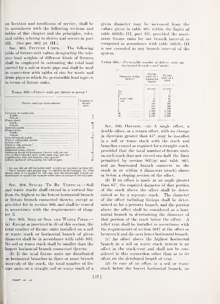
Sec. 803. Fixture Units. — The following
table of fixture-unit values designating the rela-
tive load weights of different kinds of fixtui'es
shall be employed in estimating the total load
carried by a soil or waste pipe and shall be used
in connection with tables of size for waste and
drain pipes in which the permissible load is given
in terms of fixture units.
Table 803.
—
Fixture iinits per fixture or group '
Fixture and type of installation
Lavatory or washbasin:Public .
Private _
Water closet:
PublicPrivate
Bathtub, publicShower head:
PublicPrivate
Pedestal urinal, publicWall or stall urinal, publicService sink- _
Kitchen sink, private 2
Bathtub, privateBathroom group, privateBathroom group with separate shower stall, private..Two or three laundry trays with single trap, private 2
Combination sink and laundry tray, private -
Sewage ejector or sump pump, for each 2.5 gpm
Number of
fixture
units
21
1064
4
2
10
5
3
2
2
810
3
3
50
1 See par. 803, pt. Ill for fixture-unit weights not included in table 803.2 These fixtures and groups may be omitted in determining the total
fixture units to be applied for soil pipes but the fixture-unit weights as-
signed must be applied for separate waste lines for groups of these fixtures.
Sec. 804. Stacks To Be Vertical.—Soiland waste stacks shall extend in a vertical line
from the highest to the lowest horizontal branch
or fixture branch connected thereto, except as
provided for in section 806, and shall be vented
in accordance with the requirements of chap-
ter X.
Sec. 805. Size of Soil and Waste Pipes.—(a) Except as provided in (b) of this section, the
total number of fixture units installed on a soil
or waste stack or horizontal branch of given
diameter shall be in accordance with table 805.
No soil or waste stack shall be smaller than the
largest horizontal branch connected thereto.
(6) If the total fixture units are distributed
on horizontal branches in three or more branch
intervals of the stack, the total number of fix-
ture units on a straight soil or waste stack of a
given diameter may be incireased from the
values given in table 805 within the limits of
table 805(/!))-III, part III, provided the maxi-mum fixture units for one branch iuteiwal as
computed in accordance with table 805(6)-III
is not exceeded in any branch interval of the
system.
Table 80.5.
—
Permissible nurnher of fixture units onhorizontal branches and stacks
Diameter of pipe(inches)
Fixtureunits on 1
horizontalbranch
Fixtureunits on 1
stack
Number Number1J4 1 2
Wx 3 42 6 103 waste only 32 483 soil 20 304 160 2405 360 5406 640 9608 1,200 2, 24010 1,800 3, 78012 2,800 6, 000
Sec. 806. Offsets.— {a) A single offset, a
double offset, or a return offset, with no change
in direction greater than 45°, may be installed
in a soil or waste stack with the stack andbranches vented as required for a straight stack,
provided that the total number of fixture units
on such stack does not exceed one-half the limit
permitted by section 805(a) and table 805,
and no horizontal branch connects to the
stack in or within 4 diameters (stack) above
or below a sloping section of the offset.
(b) If an offset is made at an angle greater
than 45°, the required diameter of that portion
of the stack above the offset shall be deter-
mined as for a separate stack. Tlie diameter
of the offset including fittings shall be detei-
mined as for a primary branch, and the portion
above the offset shall be considered as a hori-
zontal branch in determining the diameter of
that portion of the stack l)elow the offset. Arelief vent shall be installed in accordance with
the requirements of section 1017 at the offset or
between it and the next lower horizontal branch.
(c) An offset above the highest horizontal
branch in a soil or waste stack system is an
offset in the stack-vent and shall not be con-
sidered in this connection other than as to its
effect on the developed length of vent.
{d) In case of an offset in a soil or waste
stack below the lowest horizontal branch, no
270988°—40 3
[1-5]

change in diameter of the stack because of the
offset shall be required if it is made at an angle
of not greater than 45°. If such an offset is
made at an angle greater than 45°, the required
diameter of the offset and the stack below it
shall be determined as for a primary branch.
Sec. 807. Horizontal and PrimaryBranches.— (a) The required sizes of hori-
zontal branches and primary branches of the
building drain shall be in accordance with
table 807, except that the permissible numberof fixture units on primary branches as given
in table 807 may be increased as provided for
in section 807 (c/).
Table 807.
—
Capacities of horizontal branches andprimary branches of the building drain
Diameter of pipe(incties)
Permissible number of fixture units^
Hori-zontalbranchat mini-mumpermis-sible
slope or
greater
Primary branch '
M 6-inchfall pe r
foot
^Mnchfall perfoot
1-4 -inchfall perfoot
Va-inchfall perfoot
Number Number Number Number NumberIH 1 2 2
Wi 3 6 7
2 6 21 263 waste only _
.
32 36 42 503 soil . _ . .. 20 24 27 364 160 180 216
480250
5 360 360 400 5606 600 600 660 790 9408 1, 200 1,400 1, 600 1,920 2, 24010 1, SOO 2,400 2, 700 3, 240 3, 78012 2, 800 3. 600 4, 200 5, 000 6. 000
1 See par. 807, pt. Ill, for method of computing permissible number of
fixture units for other slopes than those given in this table.
(6) In case the sanitary system consists of
one soil stack only or of one soil stack and one or
more waste stacks of less than 3-inch diameter,
the building drain and building sewer shall be
of the same nominal size as the primary branch
from the soil stack as given by table 807, except
that {d) of this section and the applicable rules
in paragraph 807, part III, relating to pressure
drainage may apply when the prescribed
conditions are complied with.
(c) In case the plumbing system has two or
more soil stacks each having its separate pri-
mary branch or has one or more soil stacks and
one or more waste stacks of 3-inch diameter or
larger, each soil and waste stack having its
sepaxate primary branch, the number of fixture
units for a secondary branch, the main building
drain, or the building sewer of a given diameter
and slope may be increased from the A^alue given
in table 807 for a primary branch of the samediameter and slope to the value given in table
807(c), part III, of this manual, provided that
the increase is made strictly within the principles
and rules of paragraph 807, part III.
{(I) In case there is no fixture drain or
horizontal branch connecting directly with the
building drain or a branch thereof and the lowest
fixture branch or horizontal branch connected
to any soil or waste stack of the system is 3
feet or more above the grade line of the building
drain, the permissible number of fixture units
on primary branches, secondary branches, mainbuilding drain, and building sewer, may be
increased within the limits given by table
807(</), part III, provided the increases are
made in accordance with the principles and rules
given in paragraph 807, part III.
(e) The provisions of sections 807(c) and807 (c?) shall not apply unless plans drawn to
scale showing the proposed installation in
detail in regard to the diameter, dnection,
length, and slope of the building drain and its
branches and of the building sewer have been
submitted to and approved by the authority
having jurisdiction over plumbing.
Sec. 808. Sumps and Receiving Tanks.—All building subdrains shall discharge into an
airtight sump or receiving tank so located as to
receive the sewage by gravity, from which
sump or receiving tank the sewage shall be
lifted and discharged into the building sewer bypumps, ejectors, or any equally efficient method.
Such sumps shall either be automatically dis-
charged or be of sufficient capacity to receive
the building sewage and wastes for not less than
24 hours.
CHAPTER IX. STORM DRAINS
Sec. 901. General.—Roofs and paved areas,
yards, courts, and courtyards shall be drained
into the storm-sewerage system or the com-
bined sewerage system, but not into sewers
intended for sanitary sewage only. When con-
nected with a combined sewerage system, storm
drains, the intakes of which are within 12 feet
of any door, window, or ventilating opening, if
not at least 3 feet higher than the top of such
opening, shall be eft'ectively trapped. One trap
on the main storm drain may serve for all such
[16]

connections. Traps shall be set below the frost
hne or on the inside of the building. Wherethere is no sewer accessible, storm drainage shall
discharge into the public gutter, unless other-
wise permitted by the proper authorites, and in
such case need not be trapped.
Sec. 902. Leaders AND Gutters.— (a) Lead-
ers, when placed within the walls of a building
or run in a vent or pipe shaft, shall be of cast-
iron, zinc-coated (galvanized) wrought-iron or
steel, brass, copper, or lead pipe, or of copper
tubing.
(b) Outside leaders may be of sheet metal.
When of sheet metal and connected with a build-
ing storm drain or storm sewer, they shall be
connected to a cast-iron drain extending not
less than 1 foot above the finish grade. A sheet-
metal leader along a public driveway without
sidewalk shall be properly protected against
injury.
(c) Roof gutters shall be of metal or other
materials suitable for forming an effective open
channel for collecting water and conducting it
to the leaders and suitable for making a tight
connection with the leaders. (See par. 902, pt.
IIL)
Sec. 903. Size of Storm Drains and Lead-ers.— (a) Storm drains of a building shall be of
ample size to convey the estimated storm water
from the roof gutters to the street sewer or other
approved place of discharge without overflow
and without producing dangerously high pres-
sures in any building drain or leader. The esti-
mated flow shall be based on the maximum ex-
pected rate of rainfall and estimated rate of flow
of storm sewage from other sources. The tables
in this section pertaining to leaders and building-
storm drains are based on the horizontal pro-
jection of the roof area, a rate of rainfall of 4
inches per hour and limited slopes as indicated
in the tables. (See par. 903, pt. Ill, for meth-
ods of computing the requirements for condi-
tions not covered by or in these tables.)
(b) The area drained into or by a vertical
leader or a sloping leader or connecting pipe
having a slope of K-inch fall per foot or greater
shall not exceed the values given in table
903(6).
(c) The roof area drained into a building
storm sewer or into a main storm drain or any
Table 903(^;).—Maximum roof area for leaders
Diameter of Maximumleader or pipe roof area
IncheK Square feel
.5002
9003 1, riOO
2, 20(1
1 3, 100
5 f), -100
0 S, 4008 17,400
» Drainage fittings are not generally available.
Table 903(c).
—
Maximum roof area for building stormsewers or drains
Diameterof pipe(inches)
2
3
•31/2
4
5
6
8
10
12
Maximum roof area for drains of various slopes
He-inchfall perfoot
Sguare feet
1,8003.0005,9009,800
15, 900
!.8-inch
fall perfoot
Square feel
"480750
1, 1001. 560
2, 7004, 200
8, 70015. 20024. 700
}^-inchfall perfoot
Square feet
350670
1,0501, 550
2, 150
3, 000
6,00011, 90019, 60031, 800
'/i-mchfall perfoot
Square feet
500960
1. .500
2. 2003. 100.5, 4008, 400
17, 40030, 40049, 400
» 2,''2-inch and 3;4-inch east-iron soil pipe and fittings and :JH-inchdrainage fittings are not generally available.
of its branches shall not exceed the values
given in table 903(c).
{d) Roof area or drained area as applying
in the preceding tables of this section shall be
the horizontal projection of the area, except
that where a building wall extends above the
roof or court in such a manner as to drain
onto the roof or court, due allowance for the
additional run-oft' shall be made. (See par.
903 ((i), pt. Ill, for methods of computing
allowance.
)
Sec. 904. Separate and CombinedDrains.— (a) The sanitary- and storm-di'ainage
systems of a building shall be entirely separate,
except that where a combined sanitary-and-
storm street sewer is available the storm drains
may connect to a combined sanitary-and-
storm building drain or sewer at least 10 feet
downstream from any primary branch of the
sanitary system. Connections between the
sanitary and storm systems shall be made at
the same grade by means of a single wyefitting. (See par. 904, pt. Ill, for explanation
of this requirement.)
(b) Lip to the point of combining into one
system, the sizes of the storm and sanitarv
[17]

branches shall be as required for separate
storni and sanitary systems.
In the case of a combined sanitary-and-
stoi'm building drain or sewer, or of a branch
formed by the junction of a single storm drain
or sewer and a single sanitary drain or sewer
when neither the storm nor the sanitary drain
carries more than one-half of its allowable
load as given in table 903(c), part II, and table
807(<?)-III, part III, the diameter of the com-
bined drain or combined sewer shall be at
least equal to that of the larger of the two
branches emptv'ing into it, except that m no
case shaU a combined sanitary-and-storm build-
ing di-ain or building sewer be less than 4 inches
in diameter. If either or both of the storm or
sanitary branch di-ains carry more than one-half
the allowable load, the combined drain or com-
bined building sewer shall be in accordance
with table 904-III and rules of paragraph
904, part III.
Sec. 905. Closed System Required.—Whenconnected mth a combined sanitary-and-storm
sewerage system, the building storm-drainage
piping shall form a closed system with water-
tight jomts, except for its outlet and intake
openings.
Sec. 906. Overflow Pipes.—Overflow pipes
from cisterns, supply tanks, expansion tanks,
and drip pans shall connect vrith any building
sewer, buildmg drain, or soil pipe only by meansof an indirect connection.
Sec. 907. Subsoil Sumps.—Subsoil drains be-
low the main-sewer level shall discharge into a
sump or receiving tank, the contents of which
shall bo automatically lifted and discharged
into the drainage system through a properl_y
trapped fixtiu-e or drain.
Sec. 908. Construction of SubsoilDrains.—T^Tiere subsoil drams are placed un-
der the cellar floor or used to encircle the outer
walls of a building, they shall be made of open-
jointed dram tile or earthenware pipe, not less
than 4 inches in diameter. When the building
drain is subject to backwater the subsoil drain
shall be protected by an accessibh^ located
automatic back-pressure valve before entermg
the building sev^er or drain. If such drains
are connected with the sanitary sewer or with
a combined system they shall be properly
trapped. They may discharge to an area drain.
CHAPTER X. VENTS AND VENTING
Sec. 1001. Material.—Vent pipes or tubing
shall be of cast iron, zmc-coated (galvanized)
wrought iron or steel, brass, copper, or lead.
Sec. 1002. Protection of Trap Seals.—The seal of eYeiy fixture trap m a plumbingsystem shall be adequately protected by a
properly mstalled vent or system of venting.
A stack-vent, back vent, relief vent, dual vent,
cu'cuit or loop vent, or a combination of two or
more of these forms installed in the manner and
within the limitations specified in sections 1006
to 1012, inclusive, shaU be considered as ade-
quate protection of trap seals in the sense of
this section. (See par. 1002, pt. III.)
Sec. 1003. Stack-Vents Required.—Everysoil or waste stack shall be extended vertically
as a stack-vent to at least 6 mches above the
highest horizontal branch and then to the open
air above the roof or otherwise terminated in
the open air outside the building; or the stack-
vent and vent stack may be connected together
within the building at least 6 inches above the
flood level of the highest fixture, with a single
extension from the connection to the open air.
Sec. 1004. Vent Stacks Required.—A vent
stack or main vent shall be instaUed with a soil
or waste stack whenever relief vents, back vents,
or other branch vents are requhed in two or
more branch intervals. The vent stack shall
terminate independently in the open air outside
the building or may be connected s\dth the
stack-vent as prescribed in section 1003, and
shall connect with the soil or waste stack
through, at, or below the lowest horizontal
branch or with the primary branch of the
building drain.
Sec. 1005. Distance of Trap From Vent.—Except as provided for particular fixtm-es and
forms of construction in sections 1010 and 1011,
and excepting water closets, pedestal urinals,
trap-standard service sinks, and other flxtures
which depend on siphon action for the proper
fimctionmg of the fixtm'e, each fixture trap
shall have a protecting vent located so that the
total faU in the fixtm'e drain from the trap weir
to the vent fittmg is not more than 1 pipe diam-
eter, and the developed length of drain from
trap weir to vent fitting is not less than 2 nor
more than 48 pipe diameters. A back vent or
[18]

relief vent, preferably in the form of a con-
tinuous-waste-aiid-vent, shall be installed witiiin
these limits as may be necessary for compliance
with this requirement. (See par. 1005, and
fig. 13, pt. III.)
Sec. 1006. Dual Vents Permitted.—A dual
vent for two fixture traps installed as a vertical
continuous-waste-and-vent, or a stack-vent in a
dual capacity, may be employed under the fol-
lowing conditions and no additional vents for
the traps thus vented shall be required:
(a) When both fixture drains connect with a
vertical drain or stack at the same level, and
the developed length and total fall of each of
the two fixtm'e drains are within the limits
given in section 1005. (See fig. 14A, pt. III.)
(6) When the two fixture drains connect with
the vertical drain or stack at dift'erent levels, the
difference in level of the two connections is not
gi'eater than five times the diameter of the
vertical section of drain or stack, the diameter
of the vertical section or stack up to and includ-
ing the higher connection is not less than that
requu-ed for the horizontal drain for both fix-
tures, the cross-section of the higher of the two
fixture drains is not greater than one-half that
of the vertical drain, and the developed length
and total fall of each of the two fixture drains is
within the limits given in section 1005. (See
fig. 14B, pt. III.)
Sec. 1007. Group Vents Permitted.— (a)
A lavatory trap and a bathtub or shower-stall
trap may be installed on the same horizontal
branch with a back vent for the lavatory trap
and with no back vent for the bathtub or
shower-stall trap, provided the vertical section
of the lavatory drain is of not less than iK-inch
diameter, connects with the tub or shower-stall
drain in a vertical plane, and the developed
lengths of both fixture drains are within the
limits given in section 1005. (See fig. 15A,
pt. III.)
(b) Two lavatory traps and two bathtub or
shower-stall traps may be installed on the samehorizontal branch with a dual vent for the
lavatory traps and with no back vents for the
bathtub or shower-stall traps, provided that
the horizontal branch, except the separate
fixture drains, shall be at least 2 inches in
I
diameter and the fixture drains for bathtubs or
shower stalls connect as closely as practicable
upstream from l.lic vent by means of n (li aiiiage
wye. (See fig. 1.5B, pt. III.)
(c) A lavatory trap, kitchen-sink trap, and a
bathtub or shower-stall trap may be installed
on the same horizontal bi-uiich, as in (a), pro-
vided the dual vent for the lavatory and sink
traps is installed in accordance with section
1006. (See fig. 15C, pt. III.)
Sec. 1008. Yoke and Relief Vents.—Bath-
room groups, each consisting of a water closet,
lavatory, and a shower stall or bathtub with
or without shower head, may be installed on a
soil stack with any of the following forms of
group venting:
(a) Two bathroom groups, or one bathroom
group and kitchen sink or kitchen-sink-and-
tray combination, may be installed in the high-
est branch interval of the soil stack or on a
vertical yoke-vented branch not less than 3
inches in diameter with no branch vents other
than the yoke vent, provided each fixture
drain connects independently to the soil stack
or with the water-closet drain (closet bend) in
the highest branch interval and each fixture
drain in all except the highest branch interval
connects independently with the yoke-vented
branch or with the water-closet drains (closet
bends) within the limits given in section 1005.
(See fig. 16, pt. III.)
(b) One bathroom group with group vent-
ing in accordance with section 1007(a) and with
the horizontal branch connected to the soil
stack at the same level as the water-closet drain
or connected to the water-closet drain (closet
bend), or a bathroom group and kitchen sink
with connections to the stack in the samemanner and with group ventmg in accordance
with section 1007(c), may be installed m the
same branch interval of a soil stack within the
limits of permissible fixture units for one soil
stack and branch intervals (sec. 805(6)), pro-
vided that a relief vent is installed from the
water-closet branch drain in the third branch
interval from the top and in each lower branch
interval. (See fig. 19, pt. III.)
(c) Two bathroom groups with group vent-
ing in accordance with section 1007(a) or
1007(6), or two bathroom groups and two
kitchen sinks with group venting in accordance
with section 1007(c), may be installed in the
same branch interval of a soil stack, provided
]

a relief vent is installed for the second andlower branch intervals from the top. (See figs.
18 and 20, pt. III.)
(d) In all cases the relief vent required
under (a), (b), or (c), may be a dual vent and
the size shall be in accordance with section 1015.
Fittings that combine the effects of two or morestandard fittings in one casting may be per-
mitted. (See also par. 1008 and figs. 13 to 20,
pt. III.)
Sec. 1009. Circuit Vents and LoopVents.— (a) A group of fixtures in line (bat-
tery) on the same floor or level may be installed
on one horizontal branch with a circuit or loop
vent connected to the horizontal branch in
front of the last fixture drain, within the Hmits
given in table 1009(a), provided relief vents
connected to the horizontal branch in front of
the first fixture drain are installed as follows:
In each branch interval, if the total fixture
units installed in the branch exceeds one-half
the number given in table 1009(a), except that
no relief vent shall be required in the highest
branch interval of the system or in any branch
interval if the total number of fixture units on
the stack above the horizontal branch does not
exceed the limits for one stack given in table
805 and the number of fixtures on the circuit-
or loop-vented horizontal branch does not ex-
ceed two for a 2- or 3-inch horizontal branch or
does not exceed one-half the permissible num-ber in column 2 of table 1009(a) for 4-inch and
larger horizontal branches. A dual relief vent
for two circuit- or loop-vented horizontal
branches in the same branch interval may be
installed.
Table 1009(a).
—
Limits for circuit and loop venting
(1) (2) (3)
Diameter of
horizontalbranch!
W ater clos-
ets, pedestalurinals, ortrap-stand-ard fixtures
Fixture unitsfor fixtures
other thandesignated in
column 2
Inches2
3
NumberNone
2
NumberG
20
4
5
6
8
16
24
60120
180
(6) The limits for circuit- or loop-vented
horizontal branches may be increased to one
and one-half times the values given in table
1009(a) for 3-inch and larger branches whenrelief vents are installed so that there is a relief
vent inside the first fixture drain, the numberof fixtures or fixture units outside the last relief
vent does not exceed the limits given in columns2 and 3 of table 1009(a), and the number of
fixture drains between any two successive relief
vents does not exceed two for a 3-inch, three
for a 4-inch, five for a 5-inch, or eight for a
6-inch or larger horizontal branch.
(c) Two lines of fixtures back-to-back (double
battery) shall not be circuit- or loop-vented on
one branch, but each line may be installed on
a separate branch and circuit- or loop-vented.
(See figs. 21 and 22, pt. III.)
Sec. 1010. Vents for Flat-Bottoivied Fix-
tures.—The trap and fixture drain not exceed-
ing 2 inches in diameter of a single fixture
having a relatively flat bottom at least 200
square inches of which slopes toward the outlet
with a fall not exceeding )i inch per foot, or
the trap and fixture drain from a group of not
more than thi'ee such fixtures, may be installed
with a vertical section of the fixture drain not
exceeding 24 pipe diameters in length at a dis-
tance not exceeding 10 pipe diameters from the
trap weir, with a total length of sloping drain
not exceeding 72 pipe diameters, with no back
vent, provided that the fixture drain is the
highest drain on the soil or waste stack or on a
yoke-vented vertical section of a horizontal
branch. If the total developed length of the
sloping sections of the drain from the fixture to
the stack-vent or relief vent exceeds 72 pipe
diameters (9 feet for iK-inch diameter or 12
feet for 2-inch diameter), a back vent to the
first vertical section of the drain or a continuous-
waste-and-vent relief vent at or within this
prescribed maximum distance shall be installed.
(See par. 1010, and fig. 23, pt. III.)
Sec. 1011. Vents for Resealing Traps.—If
a resealing trap of approved design is installed
for a fixture or a group of not more than three
fixtures, the limits given for venting in section
1010 shall apply. (See par. 1011, pt. III.)
Sec. 1012. Fixtures at Base of MainVent.—A group of not more than three fixtures,
none of which discharge greasy wastes, may be
installed on a main vent or vent stack below
the lowest branch vent, provided the load does
not exceed one-half the allowable load by table
[20]

807 oil a horizontal brancli of llic saiuc (liaiiu'ter
as the mam vent. (See par. 1012, pt. 111.)
Sec. 1013. Size and Length of MainVents.—Vent stacks or main vents shall have
a diameter of at least one-half that of the soil
or waste stack, and shall be of larger diameter in
accordance with the limits of length and numberof fixture units as given in table 1013. Thelength of the main vent for application with
table 1013 shall be the total developed length as
follows
:
(a) From the lowest connection of the vent
system with the soil stack, waste stack, or
primary bi'anch to the terminal of the vent, if it
terminates separately to the open air;
(6) From the lowest connection of the vent
system with the soil stack, waste stack, or
primary branch to the stack-vent plus the
developed length of the stack-vent to its ter-
minal in the open air, if the stack-vent and vent
stack are joined with a single extension to the
open air.
Table 1013.
—
Size and length of 7nain vents
Diameterof soil or
waste stack(inches)
Number
of
fixture
units
on
soil
or
waste
stack
Maximum permissible developed length of vent
a>
oa
c>
a2-inch
vent
0>
Oa
3-inch
vent
4-inch
vent
5-inch
vent
'
6-inch
vent
8-inch
vent
VA 2
824
40
80310620750
1,5001,4402,8803, 1006,200
Feet75
7028
Feet Feet Feet Feel Feet Feet Feet Feet
m 150
70
20
18
2 3008075
3022
3 26024095702820
65060024018070502018
3
4 1,0007503202409570
3025
4
5 1,000750240180
8060
51,000^
750350250
6^ -
6
8 1, 100
8008-
Sec. 1014. Size and Length of Stack-
Vents.—Stack-vents shall be of the same diam-
eter as the soil or waste stack, if the soil or
waste stack carries one-lialf or more of its
permissible load by table 805 or has horizontal
branches in more than two branch intervals.
If the soil or waste stack carries less than one-
half its permissible load and has horizontal
branches in not more than two bi'anch intervals,
the stack-vent may be of a diameter not less
and a length not greater than required by table
1013.
Sec. lOlfj. Sizi-: ok Hack Veni's and liKi>noF
Vents.—The nominal diameter of a back vent,
when required, shall be not less than 1 '4 inches
nor less than one-half the diameter of I lie ili nin
to which it is connected, and under conditions
that require a relief vent for approved forms of
group venting (see sees. 1007, 1008, and 1009),
the sum of the cross sections of all vents in-
stalled on the horizontal branches in one l)ranch
interval shall be at least equal to that of cillnT
the main vent or the largest horizontal bi-anch
in the branch interval.
Sec. 1016. Size of Circuit and LoopVents.— (a) The nominal diameter of a circuit
01' loop vent and the first relief vent as required
by section 1009(a) shall be not less than one-
half the diameter of the horizontal branch thus
vented. Under conditions that requii-e a relief
vent (see sec. 1009) the sum of the cross-
sections of the circuit or loop and relief vents
shall be at least equal to that of either the main
vent requii-ed or the horizontal brancli. In
determining the sum of cross sections for this
requu'ement all relief vents connected to the
horizontal branch may be included.
(b) Additional relief vents, installed in com-pliance with section 1009(6), shall be not less
in diameter than one-half that of the largest
fixture branch connected to the horizontal
branch.
Sec. 1017. Relief Vents for Offsets.—The relief vent requii'ed for an oft'set, as pre-
scribed by section 806(6). shall be installed
either as a vertical continuation of the lower
section of the soil or waste stack or as a side
vent connected to the lower section of the soil
or waste stack between the oft'set and the next
fixture or horizontal branch b<>low the oft'set.
The size of the required relief vent shall be
determined as follows:
(a) If the stack-vent from the upper section
of the soil or waste stack is equal to that of the
upper section, the relief vent shall not be
smaller than the main vent of the stack system;
(6) If the stack-vent from the upper section
of the soil or waste stack is smaller in diametei'
than that section, it may be the same diameter
as the main vent required, in which case the
diameter of the relief vent for the oft'set shall
be equal to that of the lower section and shall
be extended to the open air without reduction
[21]

ill size or may hi' conncctt'd to tlie main vent or
stack-vent, provided the one to which it is
connected is of eqnal or greater diameter.
If horizontal branches connect to any soil or
waste stack between two offsets each offset
shall be vented as required in this section.
Sec. fOfS. Frost Closure.—In cold climates
ade(|uate provision shall be made to guard
against frost closure of vents.
Sec. f0f9. Location of Vent Terminals.—(a) No vent terminal from the sanitary drain-
age system shall be within 12 feet of any door,
window, or ventilating opening of the same or
an adjacent builcHng unless it is at least 3 feet
liigher than the top of such opening. Exten-
sions of vent pipes through a roof shall ternu-
nate at least 1 foot above it and shall be propei'ly
flashed. Vent terminals extending througli
walls shall not terminate within 12 feet horizon-
talh' of any adjacent building line, shall be
tiu'iied to provide a horizontal opening down-
ward, shall be effectively screened, and shall be
properly flashed, calked, or otherwise sealed.
(6) In the event that a structure is built
higher than an existing structiu'e, the o\\aier of
the structure shall not locate windows within
12 feet of any existing vent terminal on the
lower sti'uctm'e, unless the owner of such higher
structure shall defray the expenses of, or shall
himself make, such alterations as are necessary
to conform with the provisions of this section.
Sec. 1020. Vents Not Required.— (a) Novent shall be required for a leader trap, back-
water trap, oi' STibsoil catchbasin trap.
(6) No vent shall be required for the trap
of a basement or cellar-floor drain or area
drain, provided such (h'ain branches mto the
building drain or a branch thereof at least o
feet downistream from any soil or waste stack,
the length and fall of the floor or area drain
are within the limits of section lOOo, the load
on the budding drain or any of its branches
does not exceed the limits in table 807. and the
builduig drain is not subject to backwater
effects.
Sec. 1021. Vents Prohibited.— (a) No back
vent shall be installed within two pipe diameters
of the trap weir.
(b) Except as permitted in sections 1006,
1007, 1008, 1009, and 1012, no wet vent shall
be uistalled.
CHAPTER XI. INDIRECT CONNECTIONSTO WASTE PIPES
Sec. 1101. Indirect Wastes.—Waste pipes
from the following shall not connect directly
with any building drani, soil, or waste pipe: a
refrigerator, ice box, or other receptacle where
food is stored; an appliance, device, or apparatus
used in the preparation or processing of food
or drinlv; an appliance, device, or apparatus
using water as a cooling or heating medium;a sterilizer, water still, water-treatment device,
or water-operated device.
Such waste pipes shall in all cases emptyinto, and above the flood level of, an open
plumbing fixture or shall be comiected indi-
I'ectly to the inlet side of a fixture trap. In-
(Urect waste connections shall not be located
in inaccessible or unventilated cellars or other
spaces. (See par. 1101, pt. III.)
Sec. 1102. Size OF Refrigerator Wastes.—Refrigerator waste pipes shall he not less than
1/4 inches in diameter for one opening, VA
inches for 2 or 3 openings, and 2 inches for 4
to 12 openings. Each opening shall have a trap
and clean-out so installed as to permit proper
flushing and cleaning of the waste pipe.
Sec. 1103. Overflow Pipes.—Overflow pipes
from a water-supply tank or exhaust pipes from
a water lift shall not be directly connected with
any building dram or with any soil or waste
pipe, but shall discharge outside the building,
or into an open fixture as provided in section
1101.
CHAPTER XII. MAINTENANCE
Sec. 1201. Defective Plumbing.—Any part
of the plimibuig system foimd defective or in
an insanitary condition shall be repaired, reno-
vated, replaced, or removed within 30 days
upon written notice from the authority having
jurisdiction over pluml>ing.
Sec. 1202. Temporary Toilet Facilities.—Toilet facilities provided for the use of workmenduring the construction of any building shall
be maintained in a sanitary condition.
Sec. 1203. Condensate and Blow-Off Con-
xections.—No direct connection of a steam
exhaust, boUer blow-off, or drip pipe shall be
made with the building-drainage system. Waste
w ater when discharged into the building-drain-
[22]

age system shall be at a temperature not higher
than 140° F. Where higher temperatures exist
proper cooling methods shall be provided.
CHAPTEE XIII. INSPECTION ANDTESTS
Sec. 1301. Inspection.—All piping, traps,
and fixtures of a plumbing system shall be in-
spected by the authority having jurisfliction
over plumbing to insure compliance with the
requirements of this manual and the iiistallation
and construction of the system in accordance
with the approved plans and the permit.
Sec. 1302. Tests Required.—Every plumb-
ing system shall be subjected to tests for tight-
ness. The complete water-supply system of the
building shall be subjected to a water or air-
pressure test. The drainage system within or
under the building shall be subjected to a water
or air-pressure test before the pipes are con-
cealed or the fixtures are set in place, and the
sanitary-drainage and vent system shall be
subjected to a final smoke or air-pressure test
after the system has been completed and the
fixture traps have been connected. The author-
ity having jurisdiction over plumbing may re-
quire the removal of any plug or cap duiing the
test to determine whether the pressure has
reached all parts of the system. He may modify
or change the order of any of the tests prescribed
in sections 1305, 1306, and 1307, or may substi-
tute a different test to meet special conditions;
provided that the tests used are, in his opinion,
as effective as those required in the sections
enumerated.
Sec. 1303. Notification for Test.— (a) It
shall be the duty of the plumber to notify the
authority having jurisdiction over plumbing
and the owner, or his authorized agent, orally,
by telephone, or in writing, not less than one
working day before the work is to be inspected
or tested.
(b) It shall be the duty of the plumber to
make sure that the work will stand the test
prescribed before giving the above notification.
(c) If the authority having jurisdiction over
plumbing finds that the work will not stand
the test, the plumber shall be required to re-
notify the authority.
(d) If the authority having jurisdiction over
plumbing fails to appear within 24 hours of
the time set foi' any inspccttoii or test,, llie
inspection or test shall be iiiiuh' by the plumber
and the plumber requinid to file an affidavit
with the authority having jurisdiction over
plumbing and with the owner. T\\(' ,iffi(l;i vit
shall state that the work was installc'd in
accoi-dance with this manual and the approved
])lans and permit, that it was free from defects,
and that the required tests were made and the
system is free from leaks; also wluither the
owner or his authorized agent was present
when such inspection or tests were made, or
was didy notified.
Sec. 1304. Labor and Equipment for
Tests.—The equipment, material, power, and
labor necessary for the inspection and test
shall be furnished by the plumber, unless
otherwise provided by the authority having
jurisdiction over iilumbing.
Sec. 1305. Tests of Drainage System.—(a) A water test may be applied to the system
in its entirety or in sections. If applied to the
entire system, all openings in the piping shall
be tightly closed, except the liighest opening,
and the system filled with water to the point
of overflow. If the system is tested in sections,
each opening shall be tightly plugged (except
the highest opening of the section under test)
and the section shall be filled with water. In
testing successive sections, at least the uppei
10 feet of the next lower section shall be re-
tested (except the uppermost 10 feet of the
system) and shall have been subjected to at
least a 10-foot head of water.
The water level shall remain constant with-
out any further addition for sufficient time to
inspect the entire section imder test, but in no
case less than 15 minutes.
(b) In place of the water test, an air test
may be applied as follows: With all openings
tightly closed, air shall be forced into the
system until there is a uniform pressure suffi-
cient to balance a column of mercury 10
inches in height (or 5 pounds per square inch)
on the entire system or section under test.
The air pressure shall be maintained on the
system or section without any further addition
of air for a sufficient time to determine tightness
but in no case for less than 15 minutes. (See
par. 1305 (b), p. III.)
Sec. 1306. Final Test.—After all fixtures
2709S8°-^0 4 [23]

hare been permanontlT connected and all trap
seals filled with water, a smoke or air test mider
a pressure of approximately 1-incli water
cohunn shall be applied to the sanitary system.
In the case of a smoke test, a thick penetrat-
ing smoke produced by one or more smoke
machines (not by chemical mixtures'! shall be
introduced into the entu'e system through a
suitable opening. As the smoke appears at the
stack openings, they shall be closed and a pres-
sure equivalent to 1-inch water colunni shall
be applied.
Sec. 1307. Tests of the Watek-SffpltSystem.—The water-supply system shall be
tested in its entirety by filling the entire system
with water under a pressiu'e of at least 100
pounds per square inch, or by applying air
pressiu'e of at least 35 poimds per square inch
(70 inches of merciuy colunm) in case the water
test is not feasible or not desirable. The test
in either case shall be applied for sirfficient
time to determine tightness.
Sec. 1308. FiXAL Coxditiox.—All parts of
the plumbing system and associated equipment
shall be other^^^se tested and adjusted to workproperly and be left in good operating condition.
Sec. 1309. Separate Tests Permitted.—Tests may be made separately, as follows:
(a) The building sewer and all its branches
from the property luie to the building drain.
(6) The building drain and yard drams, m-chiding all piping to the height of 10 feet above
the highest pomt on the house di'ain. except the
exposed connections to fixtm-es.
(c) The soil, waste, vent, inside leader, and
drainage pipes which would be covered upbefore the building is inclosed or ready for
completion. The test required for (b) and (c)
may be combined.
(d) The final test of the whole system.
After each of the above tests has been madeand proved acceptable the authority having
jmisdiction over plumbing shall issue a wiitten
approval.
Sec. 1310. CovERixG OF Work.—Xo drainage
or plumbing system or part thereof shaU be
covered untU it has been mspected. tested, andapproved as prescribed in this chapter. If any
building-drainage or phunbing system, or part
thereof, is covered before being regularly m-spected, tested, and approved, as prescribed in
this chapter, it shall be uncovered upon the
direction of the authority having jmisdiction
over plumbing.
Sec. 1311. Defecth-e Work.—If inspection
or test shows defects, such defective work or
material shall be replaced and inspection andthe tests repeated.
All repairs to piping shall be made with newmaterial. Xo calking on screwed joints, cracks,
or holes wiU be acceptable.
Sec. 1312. Tests of Leaders.—Leaders andtheir roof connections within the walls of build-
ings, or their branches on an outside system
where such branches comiect with the building
dram or are less than 3 feet from the wall of the
building, shall be tested by the water or ah test.
Branches on the outside system may be tested
m connection with the house draui.
Sec. 1313. OrTBuiLDixGS.—If a stable, barn,
or other outbuilding or any part thereof is used
for human habitation, the specified inspections
and tests of the plumbing system shall be made.
Otherwise. aU drains shall be inspected, but need
not be tested.
Sec. 1314. Garages.—^For a garage or anypart of a garage the specified tests and mspec-
tions of the phunbing system shall be made.
Sec. 1315. Certificate of Approval.—Up-on the satisfactory completion and final test of
the phunbing system a certificate of approval
shall be issued by the authority havmg jurisdic-
tion over plumbing to the phmiber to be dehv-
ered to the owner.
Sec. 1316. Test of Defectr'e Pli-mbixg.—The smoke or an* test shall be used in testing the
sanitary condition of the plumbing system of a
buildmg where there is reason to believe that
the system has become defective. In plumbing
fomid defective by the authority having juris-
diction over plumbing the alterations requhed
shall be considered as new pliunbmg.
Sec. 1317. Ixspectioxs axd Tests Xot Re-
QriRED.—Xo tests or mspections shall be
requhed where a phunbing system or part
thereof is set up for exliibition piuposes and is
not used for toilet purposes and not directly
connected to a sewerage system; nor after the
repairing, or the replacement by a new one to be
used for the same purpose, of an old fixture,
faucet, or valve: nor after forcing out stoppages
and repairing leaks.
[24]

PLUMBING SYMBOLSSymbol Plan Initiak
oo
ooo
oo
O
0
-oooo—
VCO /COr.D
^ VAC
i-@H
m
D.
VS.
C.W.
hMQ.
QDMDAF.L.
I.W.
ISAW
V
R
CO.
F.D.
R.D.
RtF.
S.D.
01S.C
VAC.
M
H.Q.
nw.T.
Wli.
W.M
P.b.
Item
Drainage Line
Vent Line
Tile Pipe
Cold Water Line
Hot Water Line
Hot Water Return
Gas Pipe
Ice Wafer Supply
Ice Water Return
Fire Line
Indirect Waste
Industrial Sewer
Acid Waste
Air Line
Vacuum Line
ikfricjerator Waste
Gate Valves
Cliecli Valves
Cleanout
Floor Drain
Roof Drain
Refriqerafor Drain
Shower Drain
Grease Trap
Sill Cock
Gas Outlet
Vacuum Outlet
Meter
Hydrant
Hose Rack
Hose Rack'BuiIf in
Leader
Hot Water Tank
Water Heater
Washing Machine
Range boiler
Freestanding
of TrShowtr
Corner5ATH TUBS
o
Built-in
Pedestal Wall Hung Corner Manicure Dental
LAVAJORILS
Kitchen
Double Drain board\\yN\\\\\\\'.\N\\\\\\\
Pantry Kitchen
Single Dr Board
Combination
Sinl< 6 Tub
Vegetable
SINKS
Slop Sink
oTank Flush bidet
LAUNDRY Valve
SHOWLR TUBS TOILLTS
stall Types Wall Hung ^ Wall Recessed
Pedestal
URINALS DRINKING FOUNTAINS
Figure 1.
—
Standard plumbing symbols.
[25]

Poof /i'oof Drain
Third Floor
5€cor?d floor
Firjf Floor
dido Wall
basemenl
'fither
Conned lo Dtack Vent \ Arronqemenf
! w®
0
2:
®
W\ f
!^1
r®
® (ETi
2
1=
4=
CO.
5-0"
k ' branch Interval
5 ' branch VenI
C ' buildinq Drain
D ' buildinq 5eiver
t ' buildinq 3ub-drain
F - Circuit i^ent
0 ' Continuous Wasted Vent
H • Dry Vent
H'- Double Offsel
1 = Dual Vent Cl/nit Vent)
J ' Fixture DrainJ' = Group VentK ' Horizontal 5rone//L ' Leader
^Check
-ilahe
til ' Indirect Waste
H -- Loop l/ent
0 - Olfset
P ' Primary branchQ -- Pel/ef l/ent
R ' Return Olfset or Jumpoyer5 = Secondar/ 3ranch7 -- J/de l/ent
U -- 5oit Stack
1/ = yen! Stack
^ -- VIef Vent
t • Stock Vent
r • Yoke Vent
1 ' back Vent
OHDischarge
SumpFt Drain
co'CleaefOuf
Figure 2.
—
Illustration of definitions.
[26]

PART III. EXPLANATIONS, ILLUSTRATIONS, AND INTERPRETATIONS[Note.—Part III is divided into subdivisions called
paragraphs, each of which is numbered to correspond
with the section in part II to which it applies. Since
not all sections of part II are discussed in part III, the
paragraph numbering in part III is not necessarily
consecutive. Tables also carry the same number as
the section in part II to which they apply, with the
addition of the suffix "-III" so that when reference is
made to them it will be readily understood that they
are to be found in part III.]
Par. 101. Definitions.
Accepted standards.—Since this manual is
primarily for Federal use, preference is given to
Federal specifications in stating requirements.
These do not cover all plumbing fixtures and
materials, however, and there may be special
conditions requiring the use of other specifica-
tions. In part II, the Federal specification is
given where it exists. Where there is no such
specification and a suitable one is available
from another source, this is given. Wherethere is no suitable specification that can be
definitely ideutified, the matter is left to the
authority having jurisdiction over plumbing.
In a few cases available information not in the
form of a specification is given in the form of
tables.
Sewage-treatment plant.—The term "sewage"
is a general inclusive term used to designate the
combination of liquid-borne waste originating
in residences, business buildings, mstitutions,
and industrial establishments with or without
such gromid, surface, or storm water as maybecome mixed with it as it is admitted into or
passes through the sewers. It may be further
defined to indicate the character of the liquid
waste carried, as sanitary sewage, industrial
sewage (more commonly called industrial waste)
,
and storm sewage.
Sanitary sewage is that which originates hi
the sanitary conveniences of dwellings, business
buildings, factories, institutions, and the like.
Industrial sewage or industrial waste origmates
in an industrial process and is usually designated
by the name of that process, as for example,
"brewery wastes." Storm sewage is that
flowing in combined or storm sewers (hiring or
following a period ol rainfall aiul i-esiilting from
such rainfall.
Sewers are often designated as to type of
sewage carried. Sanitary sewers carry sani-
tary sewage, which may or may not be mixed
with some ground water which percolates into
the sewers. Storm sewers carry roof andsurface rim-ofl' following rains. Industrial
sev/ers carry industrial wastes. Where a single
sewer is designed to carry both sanitary
sewage and storm water, it is referred to as a
combined sewer.
"Sewage treatment" is a term used to desig-
nate any artificial process to which sewage is
subjected in order to remove or alter its objec-
tionable constituents and to render it less dan-
gerous from the public-health standpoint. Theterm "sewage purification" is also used in this
same connection.
Occasionally in designing a plumbing system
for a building or an institution, it is necessary
to include plans for final disposal of the sewage.
Many factors enter into any plan for treatment
of sewage; and the proper operation of the
treatment plant, no matter how small, depends
upon the careful consideration of these factors
in the design. When it is not possible to place
the design in the hands of a competent sanitary
engineer, the advice of the health agencies,
either State or Federal, should be obtained.
The usual method of disposing of sewage
where the amount is small is through cesspools
or small septic-tank subsurface disposal sys-
tems. While definite recommendations rela-
tive to design of these two types of disposal
should be obtained from the health agencies,
certain information may be of value to the
designing engineer in preparing preliminary
plans.
A leaching cesspool is one in which the solids
present in the sewage are retained and the liquid
leaches or seeps into the surrounding sod. Thesuccess of this type of disposal is dependent
upon the character of the soil and its suitabilit}^
[27]

for rapid dispersal of the liquid entering it.
Cesspools tend to seal themselves, the time re-
quired being dependent upon the character of
the surrounding soil. The solids entering the
cesspool in the sewage accumulate and at inter-
vals must be removed. In the design, there-
fore, the character of the soil must be considered
and allowances made for the storage of solids.
Where water supplies are developed in the
same area, cesspools should be located at least
100 feet away from wells or other sources of
water supply and on ground which slopes awayfrom such sources. Cesspools should not extend
into the ground-water table.
Septic-tank installations generally consist of a
watertight tank and a subsurface system for
disposal of the effluent from the tank. Thesubsurface disposal system may consist of open-
joint tile, filter trench, or subsurface sand
filter.
A septic tank is a settling tank in which it is
intended to retain the sewage solids (sludge) in
immediate contact with the sewage flowing
through the tank for a sufficient period to
secure a satisfactory decomposition of organic
solids by anaerobic bacterial action. Septic
tanks should not be confused with other types
of tanks used in connection with sewage
treatment.
The solids (sludge) retained in a septic tank
must be removed whenever there is a sufflcient
accumulation to reduce materially the liquid
capacity of the tank. The effluent from the
septic tank is only partially treated sewage and
is in a septic condition.
The effluent of a septic tank should not be
discharged to a small stream nor can it be
discharged to the surface of the ground without
nuisance.
A septic tank should be located as close as
practicable to the subsurface disposal field.
It should be located, if possible, at least 100
feet, but never less than 50 feet, from wells,
springs, or underground water-storage basins; at
a lower elevation ; and where there will be the
least danger of sewage overflowing or leaking
in such a way as to contaminate a water supply.
Grease interceptors should normally be
omitted on small septic-tank installations.
Septic tanks should be designed with a
minimum liquid capacity equal to 24 hours'
flow of sewage. The minimum-size tank should
be not less than 500-gallon liquid capacity.
When the effluent of a septic tank having a
capacity in excess of 1,000 gallons is discharged
to a subsurface tile disposal field, a dosing
tank and an automatic sewage siphon is advis-
able. Tanks of less than 1,000-gallon liquid
capacity do not require automatic siphons.
Subsurface disposal of the effluent from septic
tanks is possible where the character of the soil
will permit its absorption. The percolation
test is the most logical and practical method of
determining the suitability of the soil for this
method of disposal.
Par. 201. Installation of Piping.—Whena building drain or sewer is installed with a fall
of less than Ke inch per foot as permitted bysection 201, part II, for 10-inch and larger
diameters, the minimum permissible velocity
should be computed by the formula h/12l=
0.0008385 v^/d (for rough pipe), where h is the
fall in inches per foot, I the length of pipe in
feet, V the velocity in feet per second, and d
the diameter in feet. If it is desired to install
a building drain or building sewer at a slope
that will maintain a velocity above someselected minimum within the specified mini-
mums for the difl'erent diameters, the following
table 201-III applying to rough pipe may be
consulted. In general, the required fall in
inches per foot is given approximately by
-y/s/si— v/vi or s= Si{v/vi)'^, in which s is the fall
in inches per foot necessary to give a selected
velocity v, and Si and Vi are the fall and result-
ant velocity for pipe of the same diameter.
Table 201~III.—Approximate velocities for given slopes
and diameters
Velocities
Diameter of pipe142-inchfall perfoot
M 6-inchfall perfoot
^s-inchfall perfoot
H-inchfall perfoot
J^-inchfall perfoot
Indiesl\i
Jps0. 57 0.80
.88
fps1.14
fps1. 61
fps2.28
\y, .62 1. 24 1. 76 2. 45
2 .72 1.02 1.44 2.03 2. 88
M — .81
.88
1. 14 1.61 2. 28 3.23
3 1. 24 1. 76 2.49 3. 53
4 1.02 1.44 2.03 2.88 4. 07
5 1. 14 1.61 2. 28 3. 23 4. 56
6 1.24 1. 76 2.49 3. 53 5.00
8 --- 1. 44 2.0s 2. 88 4. 07 5. 75
10 1.61 2.28 3. 23 4. 56 6.44
12 1. 76 2.49 3. 53 5. 00 7.06
[28]

Par. 301. Quality of Materials.—Frequentreference is made in chapter III, part 11, to
Federal specifications. The title of the speci-
fication as given in the Federal Standard Stock
Catalog is presented but the specification symbolhas been omitted. This is for the reason that
such symbols change from time to time. It is
to be understood that the latest revision of the
specification, together with any subsequent
amendments, is meant. For the convenience
of the user of this manual, a list of specifications
cited in chapter III, part II, together with the
symbols m effect at the time of publication of
this manual, is given in paragraphs 303 to 325
for more positive identification. It is recom-
mended that the latest edition of the Federal
Standard Stock Catalog be consulted from time
to time to guard against the use of obsolete
symbols. When there is any occasion for
doubt, inquiry should be directed to the Federal
Specifications Executive Committee, Wash-ington, D. C.
Reference is also made in section 301, part II,
to similar and equivalent specifications. These
are for use primarily when no suitable Federal
specification is available and may be madeapplicable, through the power of the authority
having jurisdiction over plumbing, to fix
acceptable standards. There are several sources
of such standards. The chief ones are as
follows
:
American Society for Testing Materials,
260 South Broad Street, Philadelphia,
Pa.
American Standards Association, 29 WestThirty-ninth Street, New York, N. Y.
Industrial associations.
Individual manufacturers.
In the case of these standards also, the symbo'iesignations (particularly the part referring to
year of adoption) change frequently and should
be checked to see that the latest issue is being
used.
In addition to the standards already cited,
there is other useful material available for con-
sultation by authorities having jiu'isdiction
over plumbing. Included in this is a series of
Commercial Standards and a series of Simplified
Practice Recommendations, published by the
National BnicHii of St iMidiii-ds. Examples of
each series appear below:
COMMEHCIAL StaNDAKDS
Pipe nipples; brass, oopper, steel, andwrought-iron. (1940)
Standard weight malleable iron or steel
screwed unions. (1929) CS7 29
Simplified Practice Recommendations
Eaves trough, conductor pipe and fittings,
and ridge rolls. (1939) R29 39
Wrought-iron and wrought-steel pipe valves
and fittings. (1932) R57-32Range boilers and expansion tanks. (1929) _ R8-29Structural slate for plumbing and sanitary
purposes. (1928) R13~28Brass lavatory and sink traps. (1925) mime-ographed R21
Hot water storage tanks. (1925) mime-ographed R25
Metal partitions for toilets and showers.
(1929) RlOl-29
Publications not indicated as mimeographed
may be obtained by purchase from the Govern-
ment Printing Office, Washington, D. C.
Other publications and information may be
obtained from the Division of Trade Standards
and the Division of Simplified Practice, respec-
tively, both at the National Bureau of Stand-
ards, Washington, D. C.
Par. 303. Vitrified-Clay Pipe.—Federal
Specification for Pipe; Clay, Sewer. SS-P-361,
with Amendment 1, June 1935.
Standard Specifications for Clay Sewer Pipe.
A. S. T. M. Designation: C13-35.
Par. 304. Concrete Pipe.—Federal Specifi-
cation for Pipe; Concrete, Non-Pressure, Non-
Reinforced and Reinforced. SS-P-371, Febru-
ary 19, 1937.
Standard Specification for Concrete Sewer
Pipe. A. S. T. M. Designation: C14-35.
Par. 305. Cast-Iron Soil Pipe.—Federal
Specification for Pipe and Pipe Fittings; Soil,
Cast-iron. WW-P-401, with Amendment 1,
January 1937.
American Standard for Cast-iron Soil Pipe
and Fittings. A. S. A. No. A40. 1—1935.
Tentative Specifications for Cast-iron Soil
Pipe and Fittings. A. S. T. M. Designation:
A74-39T.
Par. 306. Cast-Iron Water Pipe.—Federal
Specification for Pipe; Water, Cast-iron (BeU
[29]

and Spigot and Bolted Joint). WW-P-421,with Amendment 3, April 1940.
American Standard for Cast-iron Pipe, Pit-
Cast for Water or Other Liquids. A. S. A.
No. A21.2—1939.
Tentative Specifications for Cast-Iron Pit-
Cast Pipe for Water or Other Liquid. A. S.
T. M. Designation: A44-39T.
Standard Specifications for Cast-Iron WaterPipe and Special Castings of the American
Waterworks Association, adoptedMay 12, 1908.
Par. 307. Cast-Iron Screwed Pipe.—Fed-
eral Specification for Pipe, Cast-iron; Drainage,
Vent and Waste (Threaded). WW-P-356,August 19, 1936.
Par. 308. Wrought-Iron Pipe.—Federal
Specification for Pipe, Wrought-Iron, Welded,
Black and Galvanized. WW-P-441a, Decem-ber 28, 1939.
American Standard for Lap-Welded and
Seamless Pipe. A. S. A. No. B36.3—1939.
American Standard for Welded Wrought-
Iron Pipe. A. S. A. No. B36.2—1939.
Standard Specifications for Welded Wrought-
Iron Pipe. A. S. T. M. Designation: A72-39.
Par. 309. Steel Pipe.—Federal Specification
for Pipe, Steel, Seamless and Welded, Black
and Zinc-Coated. WW-P-403a, December 28,
1939.
American Standard for Welded and Seamless
Steel Pipe. A. S. A. No. B36. 1—1936.
Standard Specifications for Black and Hot-
Dipped Zinc-Coated (Galvanized), Welded and
Seamless Steel Pipe for Ordinary Uses. A. S.
T. M. Designation: A120-36.
Par. 310. Brass and Copper Pipe.—Fed-
eral Specification for Pipe, Brass, Seamless,
Iron Pipe Size, Standard and Extra Sti-ong.
WW-P-351, with Errata 1, October 1930.
Tentative Specifications for Brass Pipe,
Standard Size. A. S. T. M. Designation:
B43-39T.
Federal Specification for Pipe; Copper, Seam-
less, Iron Pipe Size, Standard. WW-P-377,May 31, 1932.
Tentative Specifications for Copper Pipe,
Standard Size. A. S. T. M. Designation: B42-
39T.
Par. 311. Brass Tubing.—Federal Specifica-
tion for Plumbing Fixtures; (for) Land Use.
WW-P-541a, March 30, 1940.
Par. 312. Copper Tubing.—Federal Speci-
fication for Tubing; Copper, Seamless (for Use|
With Soldered or Flared Fittings). WW-T-799, with Errata 2, April 1934.
Federal Specification for Tubing; Copper,
Seomless (for General Use With I. P. S. FlangedFittings). WW-T-797, with Errata 1, August1933.
American Standard for Copper Water Tubing.A. S. A. No. H23. 1—1939.
Standard Specifications for Copper Water|
Tubing. A. S. T. M. Designation: B88-39.Par. 313. Lead Pipe.
Table 313-III.
—
Diameter and weight of lead pipe
(The following thicknesses and minimum weights are taken from thestandard of the Lead Industries Association]
LEAD SERVICE AND SUPPLY PIPE
A or S (for pressures up to 50 lb/in. 2)
Inside Weight per Outsidediameter foot diameter
Inches Pounds Inches0.798
% 1,019
H 3 1. 1561 4 1.428IM iVi 1.670m 6V2 1. 9842 SH 2. 503
AA or XS (for pressures between 50and 75 Ib/in.z)
Inches Pounds Inches
¥2 2 0. 876
% 3 1.082
% 3H 1. 2121 1.492IM 6 1. 705
8 2. 0762 13M 2. 751
AAA or XXS (for pressures between75 and lOOlb/in.2)
Inches Pounds Inches
V% 3 1.012
% 3% 1. 137
M 1.3361 6 1. 596IM 1.889
UM 2. 2722 19}^ 3.008
LEAD WASTE PIPE
Minimum recommended weight,"D" or "XL
Inside Weight per Outsidediameter foot diameter
Inches Pounds InchesiM 2V2 1.486
IV2 iVi 1.7762 i'A 2.284
5 2.753 6 3.254 7% 4. 256 9% 5. 25
6 1113-16 6. 25
[301

A more extended table is available from the
Lead Industries Association, 420 Lexington
Avenue, New York, N. Y.
Par. 314. Sheet Lead.—Federal Specifica-
tion for Lead; Sheet. QQ-L-201, January
10, 1933.
Par. 315. Calking Lead.—Federal Specifi-
cation for Lead, Calking. QQ L-156, June 5,
1934.
Par. 316. Sheet Copper and Brass.—Fed-
eral Specification for Copper; Bars, Plates,
Rods, Shapes; Sheets, and Strips. QQ-C-501,with Amendment 1, November 1936.
Federal Specification for Brass, Commercial;
Bars, Plates, Rods, Shapes, Sheets, and Strips.
QQ-B-611a, April 27, 1938.
Tentative Specifications for Brass Sheet and
Strips. A. S. T. M. Designation: B36-39T.
Par. 317. Zinc-Coated (Galvanized) SheetIron and Steel.—Federal Specification for
Iron and Steel; Sheet, Black and Zinc-Coated
(Galvanized). QQ-I-696, March 6, 1934.
Par. 318. Screwed Fittings.—Federal Spec-
ification for Pipe Fittings; Cast-iron (Thread-
ed). WW-P-501a, June 7, 1939.
Federal Specification for Pipe Fittings; Mal-
leable Iron (Threaded). WW-P-521a, June
20, 1939.
Federal Specification for Pipe Fittings; Brass
or Bronze (Threaded), 125-lb. WW-P-448,May 26, 1931.
Federal Specification for Pipe Fittings; Cast-
iron, Drainage. WW-P-491, October 20, 1938.
Federal Specification for Pipe Threads, Stand-
ard. GGG-P-351, January 9, 1934.
Par. 319. Soldered Fittings.—American
Standard for Soldered Joint Fittings. (Inquire
of American Standards Association. Also sec
par. 409.)
Par. 320. Calking Ferrules.—The following
represents customary recommended practice for
brass ferrules
:
Table 320-III.
—
Size, diameter, and weight of brass
calking ferrules
Pipe size
Actualinside
diameterLength Weight
Inches2
3
4
Inches
2M3M
Inches lb oz1
1 12
2 8
Foj- iron-body fcrrnhss, niferisiicc slioiild l)c
made to Federal Specification for Pipe and Pipe
Fittings; Soil, Cast-iron. WW-P-401, wiili
Amendment 1, January ]937.
Par. 321(a). Soldering Nij'ples.—Tlie fol-
lowing ropn'sents customary recommendedpractice for soldering nipples:
Table 321(a)-III.
—
Diameter and weight of solderingnipples
Diameter Weight
Inches lb ozm 6
VA 8
2 14
2H 1 6
3 2 04 3 8
Par. 322. Floor Flanges.—Federal Specifi-
catioii for Plumbing Fixtures; (for) Land Use.
WW-P-541a, March 30, 1940.
Par. 323. Packing.—Federal Specification
for Packing; Jute, Twisted. IIH-P-117.
Par. 324. Setting Compound.—Federal
Specification for Compound;Plumbing-Fixture-
Setting. HH-C-536, June 5, 1936.
Par. 325. Gaskets.—Federal Specification
for Gaskets; Plumbing-Fixture-Setting. HH-G-116, June 5, 1936.
Par. 402. Vitrified-Clay and ConcretePipe.
Jointing Compounds for Vitrified-Clay Pipe.—There are no generally accepted specifications
for jointing compounds for clay pipe. There
are available a number of proprietary com-
pounds prepared for this purpose. Hot-poured
jointing compounds should liquefy and flow
freely at the pouring temperature, should adhere
to the pipe, and should be sufficiently elastic
when cold to permit slight movement without
injury to joints. The compound should be of a
composition that will not deteriorate in water
or sewage. Directions in regard to packing of
joints and to heating and pouring temperatures
are usually supplied with these prepared com-
pounds and should be followed faithfully in
making the joints. Joints in horizontal or
sloping pipe are made with joint runner in the
same manner as lead joints in cast-iron except
that just enough packing to liold the pipe in
position and prevent the compound from
entering the interior of the pipe should be used
270988°-40 5
[31]

and the joint should not be calked after pouring.
One or more joints may be poured in a vertical
position without using- a joint runner, allowed
to set (harden), the joined pipes carefully
lowered into position in the trench, and the
remaining joints completed using a joint runner
as described. The joint space and packing
should be thoroughly dry and the joint space
should be completely filled with one pouring.
Cement Joints in Vitrified-Clay Pij>e.—Themortar should be freshly mixed, and of one part
Portland cement and two parts sand by weight.
A layer of mortar should be placed in the bottom
of the bell and the packing calked into it. Theremainder of the joint should then be com-
pletely filled with the mortar and the outer face
of the joint beveled. Earth should be packed
around the joint until the mortar has set, to
prevent sagging of the mortar, and the interior
of the pipe cleared of any mortar that has been
forced through the joijit.
Par. 409. Joints in Copper Tubing.—Inas-
much as no standard exists for joints in copper
tubing, reference is made to the proposed
standard of the American Standards Associa-
tion, Soldered-Joint Fittings, which is now in
preparation. Recpiirements suggested by one
manufacturer for material for fittings call for
use of cast red brass or wrought metal contain-
ing at least 85-percent copper. Soldered fittings
should be of such size that joints will be com-
pletely filled with solder by capillary action.
For further information, it is recommended that
National Bureau of Standards Building Ma-terials and Structures Report BMS58 "Strength
of Soft-Soldered Joints in Copper Tubing" be
consulted. This report contains most of the
data upon which the proposed American
Standard is based. It is obtainable from the
Government Printing Office, Washington, D. C,for 10 cents a copy.
Par. 413. Increasers and Reducers.—Theprohibition of an enlargement chamber or
recess with ledge, shoulder, or reduction in size
of pipe in section 203, part II, and section 413,
part II, is not to be construed as prohibiting
enlargements such as formed by standard wyeor other standard branch fittings, as pro-
hibiting the recess formed in the vertical run of
fittings in soil or waste stacks in oi'der to
accommodate several branch connections unless
a definite ledge is formed thereby, or as pro-
hibiting the enlargement of a 3-inch closet
bend to 4 inches at its inlet in order that a
standard 4-incli floor flange may be used in
making floor connections for water closets.
It is to be construed as prohibiting any enlarge-
ment, recess, or ledge through faulty design of
fittings or poor workmanship that would forma dam or otiier obstruction in the direction of
flow.
Par. 501. Types and Sizes of Traps.—Theprovisions of section 501, part II, are intended
in general to require the use of properly vented
P-traps with plumbing fixtures whenever con-
ditions make the installation of that form of
trap feasible. The provision regarding "self-
cleaning" is relative, since there is no form of
trap that does not become fouled by deposit or
sediment under certain conditions of service.
A trap having a tubular water passage of uni-
form cross-section, as exemplified by tubular
P-traps, is generally regarded as being the
nearest possible approach to self-cleaning.
To a limited extent, standards for fixture
traps are covered by Federal Specification for
Plumbing Fixtures; (for) Land Use, WW-P-541a. A standard covering traps for plumbing
fixtures is in course of preparation by Sectional
Committee A40 of the American Standards
Association. A Simplified Practice Recom-mendation (No. 21) is available covering brass
lavatory and sink traps. Recommendations for
lead traps and lead bends may be obtained
from the Lead Industries Association. Such
material should be useful to the authority
having jurisdiction over plumbing in deter-
mining proper standards.
Par. 502. Prohibited Traps.—The provi-
sion relative to "partitions" in traps, section
502, part II, applies only to traps constructed
separately from and attached to fixtures in the
process of installation. The purpose of the
provision is to prevent the use of traps with
inner partitions not accessible for inspection
through which, if defective, the water seal of
the trap might be lost without giving any
indication that it had been lost. It is assumed
that each trap acceptable under this provision
will have been carefully inspected or tested
during the process of manufacture and that the
administrative authority will have inspected a
[32]

Figure 3.
—
Continuous waste.
sufficient number of traps before approval to
satisfy himself that the quality and workman-ship of traps installed in accordance with the
requirement are uniformly good and that the
hidden walls are uniformly without defects, are
of sufficient thickness, and are accessible for
inspection. The provision of section 502,
regarding double-trapping, is not to be con-
strued as preventing the installation of a
grease interceptor, sand interceptor, or oil
interceptor in addition to a fixture trap or
traps, provided a vent intervenes between such
interceptor and fixture traps.
Par. 601. Quality of Water.—Where the
water supply of a building or institution is
obtained from a public supply, the designing
engineer of the plumbing system or the engi-
neer or plumber making the installation has no
control over the quality of the water. When an
independent supply is to be installed, it is then
the responsil)ility of both the designing and
installing agencies to make sure that the water
is satisfactory from the standpoint of quality
(both bacterial and chcmicalj and of quantity.
Independent supplies are generally from
ground-water sources, either wells or spi'ings.
Development of indepen(h>nt supplies fi'om
surface sources should be undertaken only
under the direction of a sanitary engineei-
versed in water treatment.
In the development of a ground-water supply
there are many factors to consider if a safe and
satisfactory supply is to be obtained. It is
suggested that the advice of state or Federal
health services be obtained before plans for
developing a supply are formulated.
The publication entitled "Ground WaterSupplies," Supplement 124 to the Public
Health Reports, covers the subject thoroughly.
This publication can be obtained from the
Superintendent of Documents, Washington,
D. C, for 5 cents per copy.
The bacterial quality of any supply should
conform to the "Drinking Water Standards"
adopted by the Department of the Treasury,
June 20, 1925, on recommendation of the U. S.
Public Health Service, as they exist at present
or may be modified in the future. Information
relative to standards may be obtained from the
U. S. Public Health Service, Washington, D. C.
Bacteriological examination of water from
newly developed wells and springs quite gen-
erally indicates contamination, even where the
S//p Joint Inkf
Ouf/ct
Croivr? We/r
Figure 4.
—
De-pth of trap seal.
[33]

installation is properly made, if care is not taken
to sterilize the well and pumping equipment
thoroughly after the installation has been com-
pleted. It is also desirable to sterilize the enthe
system after installation and before use.
Sterilization may be accomplished by intro-
ducing into the well or spring one of the chlorine
compounds in amounts sufficient to give a
clilorine dosage of 50 parts per million in the
water. The chlorinated water should be cir-
culated throughout the entire system and
allowed to remain in the system 8 to 10 hours,
after which the system should be flushed with
water from the well or spring.
No samples of water for bacteriological ex-
amination should be taken until after steriliza-
tion of the supply and equipment and the re-
moval of all traces of chlorine from the water.
Dnections regarding sterilization may be ob-
tained from any of the'health agencies.
Par. 602 (<i). Protection From Backflow.
Air Gaps.—An approved ah gap shoidd be
provided in all overrim supplies. The following
extract, from Federal Specification WW-P-541a, gives accepted standards of aii- gaps for
overrun water supplies
:
Fixtures with faucets or other supply fittings properly
assembled shall provide between the level of all supply
openings and the water level at point of unrestricted
external overflow a mean vertical distance or air gap
as specified in table X.
Table X.
—
Air gaps
^3idz Wall
A Outlet Horizontal
Fixture and fitting
(1)
Minimum air gap
For ordi-nary condi-tions. (Seenotes 1
and 2)
(2)
For spoutnear wall.
(See notes1 and 2)
(3)
Lavatory supplies with effective opening notgreater than J 9 inch _ .
Inches
LOO
L 50
2. 00
(')
0. 75
Inches
1. 50
2. 25
3.00
Sinlf, laundry tray, and bath (gooseneck) faucetswith effective opening not greater than ?4 inch_
Overrim bath fillers with effective opening notgreater than 1 inch. _ . __.
Any fitting with effective opening greater than1 inch _ . ...
Drinklng-fountain nozzles
> 2x effective opening.i> 3x etTective opening.
Note 1.
—
Spout near wall.—If any vertical wall ex-tending to or above the horizontal plane of the spoutopening is closer to the nearest inside wall of the spoutopening than four times the diameter of the effective
opening, the air gap shall be as specified above for spoutnear wall, column 3.
Note 2.
—
Spout set at an angle.—Should the plane of
the end of the spout be at an angle to the surface of thewater, the mean gap is to be taken as the basis for meas-urement, except for drinking-fountain nozzles, in whichcase the gap to the lowest point of the nozzle openingshall be taken.
Backflow Preventers.—When any supply pipe
is installed with a fixture or receptacle in such
a manner that an approved air gap is not
provided, an approved backflow preventer
should be installed in the supply fitting or con-
nection on the outlet side of the control valve.
3 Outlet at an AnqU
FiGUBE 5.
—
Illustration of air gap.
[341

Approval of a backflow preventer should l)e
given on the basis of tests made by a reeognized
testing laboratory to determine its effectiveness
under the conditions under which it is to be
installed and used. Requirements for backflowpreventers for ballcocks for flush tanks are
given in Federal Specification WW-P-541a,paragraphs E-37c, F-7a, and F-7b, and require-
ments for flush valves for water closets andurinals in paragraphs E-38f, F-8a, and F-8b.
Par. 604. Size of Building Main.—Themandatory requirement of section 604, part II,
that "the building main, including the water-
service pipe, shall be of sufficient size to permit
a continuous ample flow of water to the building
under the average daily minimum service pres-
sure in the street main," states a desirable
attainment rather than one that can be pro-
vided for with certainty, since the rate of flow
in a pipe of given size depends on many factors,
some of wliich caiuiot be determined accurately
in advance. The term "ample flow" in tins
requirement means a flow ecpial to or gi'eat(!r
than the estimated demand. In (h-signing tlie
water-supply system of a large building and to
a lesser extent that of a small building, the
engineer will of necessity exercise his judgmentin the selection of the matoi-ial to use, the siz(!S
of pipe to install, and the most efficient pipe
lay-out, based on available information pertain-
ing to the particular locality and building. It
is assumed that the authority having jurisdic-
tion over plumbing will exercise correspondingly
intelligent judgment in inspecting plans andspecifications for approval, if the plans for the
water-supply system are subject to his approval.
For the use of the engineer in laying out the
water-supply system of a building, there are
given in the foUowing pages a table (table
604-III(a)) of load-weight values in fixture
500
O 500 1000 1500 2000 2500 JOOOfixture. Units
Figure 6.
—
Curve for estimating supply demands.
[35]
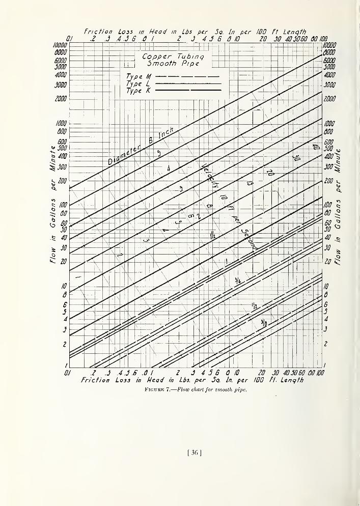
10000
0000
60005000
4000
Friction Lo55 in H(zad in Lbs per 3q. In per 100 Ft Length0.1 2 J .4 .5 6 .0 I 2 J 4 J 6 d 10 20 JO 4050BO 00 100
0.1 .2 .5 .4 .5 .6 .0 I 2 5 4 5 B Q 10 20 50 40 5060 00 100
Friction Loss in Hzad in Lbs. per Jq. In. per ZOO Ft. Lenqtf?
Figure 7.
—
Flow chart for smooth pipe.
[36]

Friction Loss in Hzad in Lbs. pzr 5q. In per 100 Ft Length
0.1 .Z .J .4 .3 .6 .6 I 2 J 4 5 6 0 10 ZO 30 ^05060 00 100
Friction Loss in I4zad in Lbs. per Jq. In per 100 Ft Length
Figure 8.
—
Flow chart for fairly smooth pipe.
[37]

Friction Loss in Head in Lbs. per 5q. In. per 100 M Lcnqtli
0.1 .2 J .4 .J .6 .0 i 2 J 4 3 6 d 10 20 30 40JO60 00 lOD
Friction Loss in Head in Lbs. per 3q. In per 100 Ft Lenqtti
Figure 9.
—
Flow chart for fairly rough pipe.
[38]

Friction Loss in Nead in Lbs per Jo In per 100 Ft Length
ai ./ J .4.3.B .6 1 2 J 4 5 6 d 10 20 JO 4050BO dO 100
Friction Loss in Head in Lbs per J<? In per 100 Ft Lenqtti
Figure 10.
—
Flow chart for rough pipe.
[39]

tion useful in the selection of serviceable pipe
sizes.
Table 604-III(a).
—
Fixture-unit ratings for estimatingwater-supply demands '
J .4 .S 6 .S / 2 3 4 JG7Diameter in inc/ies
Figure 11.
—
Relation of flow to diameter of pipe for
friction loss of 10 Ib/in.'^ per 100 feet.
units; a curve (fig. 6) for estimating the ex-
pected demand in gpm for total load in fixture
units; four charts (figs. 7 to 10) giving the
capacity of pipes relative to diameter, rough-
ness, and friction loss in head; a chart (fig. 11)
showing the relation of flow to diameter for a
given friction loss and for different degrees of
pipe roughness; and a table (table 604-111(6))
giving suggested allowances for standaixl pipe
fittings, in equivalent lengths of pipe of the
same diameter. A table (table 604-III(c))
giving the nominal and actual diameters of
new copper tubing, new steel pipe, and newbrass pipe (I. P. S.) and a table (table 604-
III((i)) illustrating the eftects of corrosion
and caking on the capacities of water-supply
pipes are included as pertinent general informa-
Fixture and type of installation 2
Lavatory or washbasin:Public or office toilet
PrivateWater-closet flush valve:
Public or office toilet
PrivateWater-closet flush tank:
Public or office toilet
PrivateUrinals, public or office toilets:
Pedestal-urinal flush valveWall- or stall-urinal flush valveWall- or stall-urinal flush tank
Bathtub or separate shower head:Public or office
PrivateBathroom group, private:
With flush-valve supplyWith flush-tank supplySeparate shower head
Kitchen sink:Public, hotel, or restaurantPrivate
Service sink ',
Laundry trays (1 to 3) or corribination fixture
Numberof fixtureunits '
' For supply outlets likely to impose a continuous demand when other
fixtures are in extensive use, add the estimated continuous demand to the
total demand for fixtures. For example, 5 gpm for a sill cock or hose con-
nection is a liberal but not excessive allowance.
2 Fixtures not listed in the table, if installed in relatively small numberscompared to the rated fixtures, may usually be safely ignored in estimating
for the building main and large distributing branches. If installed in
sulTiciently large numbers to justify their consideration, they may be
assigned flxture-rmit ratings on the basis cf a comparison with a rated
fixture that uses water in similar quantities and at similar rates. For
example, if washsinks or washtroughs with multiple supply outlets are
to be installed, each supply outlet may be considered as comparable in
demand to that of a washbasin in public service.
' The ratings given in the table are for the total hot- and cold-water
demand. The engineer will need to exercise judgment in estimating
separately for hot- and cold-water demands, depending to a large extent
on conditions. The following is suggested as ample allowances under
favorable conditions: For main hot-water branches allow % of the total
fixture units as given by the table for all fixtures using hot water: for maincold-water branches compute the total fixture units separately for fixtures
that are and are not supplied with hot water and add H of the total for
fixtures that are supplied with hot water to the total for fixtures that are
supplied with cold water only. If the character of the water is such as to
produce corrosion and caking in the hot-water lines, it may be advisable
either to allow the full table rating in estimating the demand for hot-
water branches or to allow for a decrease in diameter by selecting the next
larger size of pipe than that indicated by the computed estimate.
< Ignore demands for service sinks except for hot-water supply and
that for the cold-water branch to the fixture itself. Other fixtures,
similarly used out of hours, may be treated similarly.
Application oj Flow Charts, Figures 7 to 10.—The chart in figure 7 applies to smooth newcopper tubmg v/ith recessed (streamlined)
soldered joints and to the actual sizes of the
types indicated on the diagram. It may be
applied also to any correspondingly smooth
pipe such as brass pipe (I. P. S.) with recessed
fittings by taking into account any differences
in actual diameter from the diameters shown
[40]

in figure 7. (See fig. 11 for variatioi) in Howwith variation in diameter for different degrees
of roughness.)
The ciiart in figure 8 apphes to new wrought-
h'on or steel (fairly smooth) pipe and to actual
diameters of standard -weight pipe.
The chart in figure 9 applies to fairly rough
pipe and to actual diameters which in genei'al
will be less in service than the actual diameters
of the new pipe of the same kind. Hence, for
close estimates in the selection of pipe sizes it
will be necessary also to estimate the probable
change in diameter in service and to apply a
correction, or otherwise to make an ample
allowance.
The chart in figure 10 applies to very rough
pipe and actual diameters. Again, close esti-
mates in the selection of serviceable sizes will
require estimates of the probable condition of
the pipe and change of diameter in service.
In this connection , if the character of the water
is such as to produce a material change in
diameter by reason of corrosion or caking or
both, it will be safe to assume that the pipe
falls in the category of very rough pipe.
In many cases, for either moderately or
extremely bad conditions, it will be possible to
make a satisfactory selection of serviceable pipe
sizes for water-distributing systems without
making specific estimates of the probable change
m diameter. For example, if the amount of
corrosion or caking to be expected is small, it
will, in most instances, be sufficient to refer to
figure 9. Likewise, it will be sufficient in manycases to refer to figure 10 without specific cor-
rections for bad conditions in respect to
corrosion and deposit. If there is a wide mar-
gin of capacity over the estimated demand,
it will ordinarily be safe to select the size
indicated by the applicable chart. If the
indicated size is on the border line, either the
next larger size than that indicated should be
installed or the effects of probable changes in
diameter in service should be investigated.
In all cases the engineer should bear in mind
that small distributing pipes, especially hot-
water pipes, are likely to be completely closed
after a few years in service if corrosion and
caking are excessive. (See table 604-111(6?),
pt. Ill, for relative effects on different pipe
sizes.)
[
Table (iOI JJI(/(j.
—
Allowance in cquivaleiU Uru/lh ofpipe for friction loss in valves and threaded jitiings
Equivalent length of pipe for various fittings
Diameterof fitting
90°
stand-ard ell
45°
stand-ard ell
90°
side
tee
Coup-
straight
tG6
Gatevalve
Qlobovalve
Anglevalve
Inches Feel Feet Feet Feel Feel Feel Feet% 1 0.6 1.6 0.3 0.2 8 4
Yl0
1. 2 QO , c . 4 15 8Va. 2.5 1.5 4 .8 . 5 20 121 3 1.8 5 .9 .0 25 15M 4 2.4 6 1.2 .8 35 18
iM 5 3 7 1.5 1.0 45 222_. 7 4 10 2 1.3 55 28
7>A 8 5 12 2.5 l.H 65 343 10 6 15 3 2 80 40
3^- 12 7 18 3.0 2.4 100 504 14 8 21 4.0 2. 7 125 555 17 10 25 5 3.3 140 706 20 12 30 6 4 105 80
The friction loss in threaded fittings relative
to the friction loss in straight pipe of the samediameter for the same velocity of flow through
both will vary widely depending on the smooth-
ness to which the ends of the pipe are reamedand on the space left between the ends of the
pipe in making the joints. The allowances in
table 604-111(6), given for the most part in
round numbers, are reasonable allowances for
reasonably good workmanship with nonrecessed
threaded fittings. For recessed threaded fit-
tings and streamlined soldered fittings one-half
the allowances given in the table will be ample.
Ordinaiily, for small buildings (residences) and
for small sizes of pipe (1/2-inch and smaller)
allowances for loss in fittings may be safely
ignored if the available pressure for friction loss
is large with respect to the maximum allowable
friction loss on which the selection of sizes
is based.
Table 604-III(c).
—
Actual diameters corresponding to
nominal diameters of different kinds of pipe
Actual inside diameters
NominalTypes of copper tubing Steel 1 Brass (I. P. S.)
diameters
L M Stand- E.xtra Stand- E.\traK ard strong ard strong
Inches Inches Inches Inches Inches Inches Inches Inches
% 0.40 0.43 0.45 0.49 0.42 0. 49 0.42
H .53 .55 .57 .62 .55 .63 .54
M .75 .79 .81 .82 .74 .82 .74
1 1.00 1.03 1.06 1.05 .96 1.00 .95
Wi 1.25 1.27 1.29 1.38 1.28 1.37 1.27
iM 1.48 1. 51 1.53 1.61 1.50 1.60 1.49
2 1.96 1.99 2. 01 2. 07 1.94 2. 06 1.93
2^ 2. 44 2. 47 2. 50 2. 47 2. 32 2, 50 2. 32
3__ 2. 91 2. 95 2.98 3.07 2. 90 3. 06 2. 89
3H4
3. 39 3. 43 3. 47 3. 53 3. 36 3. 50 3. 363.86 3.91 3. 94 4. 03 3.83 4.00 3. 82
5 4.81 4.88 4. 91 5. 05 4. 81 5. 06 4.81
6 5. 74 5. 85 5.88 6. 07 5. 76 6. 13 5. 75
' For the most part, wrought-iron pipe corresponds in size to the corre-
sponding weights iif slei'l pipe, differing by not more than 0.01 inch in
diameler for iinmiiial ilianietors of 2J i inches and smaller and by not morethan U.02 inch for nominal diameters of from 3 to 6 inches.
]

Table 604-III(d).
—
Illustration of the probable effects of corrosion and caking in service on the capacities of water pipes[Steel or iron pipe (standard))
NomiDal diameter (inches)
2....
2H-
New, fairly smooth
Actualdiameter
Inches0. 488.618.820
1.04
1.371.602. 062.46
3. 064. 025. 046. 05
Flow 1
gpm2. 454. 55
9. 6018.0
37.656.0108.0173.0
310630
1, 125
1, 805
Corroded, slightly caked,fairly rough
Assumeddiameter
Indies0. 438
. 568
.770
1. 321.652. 01
2.41
3. 01
3. 974. 996.00
Flow 1
gpm1.753.307.20
13.6
28.542.582.4134
238
1, 420
Percent-age offlow innew
71.472.675.075.6
75.875.976.476.6
76.877.077.778.6
Badly caked, very rough
Assumeddiameter
Indies0. 338
.670
1.221.451.91
2.31
2. 91
3.874. 895. 90
Flow 1
gpm0. 972. 024. 658. 75
19.1
29.859. 1
94.5
170345617993
Percent-age of
flow in
new
39.645.447.448.6
50.753. 2
54.654.7
54.854.855.055.2
Very badly caked, very rough
Assumeddiameter
Indies0. 188
. 318
.520
.74
1. 071. 301.762. 16
2.763.724.745.75
Flow 1
gpm0. 26.84
2. 605. 85
13.722.647.779.0
147310575930
Percent-age offlow innew
10.618. 5
27.
1
32.5
36.440.444.045.7
47. 4
49. 2
51. 1
51.5
1 Flow is approximate for friction loss of 10 lb/in. 2 per 100 feet of pipe.
Estimating for Continuous Dernands on the
Building Water Main.—The water demand for
hose connections or sill cocks is frequently the
cause of inadequate water supply and some-
times of complete failure in water supply on the
upper floor of a building, especially if the
branches to the hose connections are sized for the
same permissible friction loss per hundred feet
of pipe as the branches and risers to the highest
level in the building. Somewhat the same
condition exists in regard to the branches to
fixtures taken oft' from the building main.
There are several ways by which robbing of
upper-floor fixtures of water by hose connections
and other branches from the building main can
be prevented: (1) by selecting the sizes of pipe
for the dift'erent branches so that the total
friction loss in each lower branch is equal to or
greater than the total loss in the riser including
both friction loss and loss in static pressure;
(2) by throtthng each such branch by means of
a valve until the preceding balance is obtained;
(3) by increasing the sizes of the building main
and risers over that required merely to meet the
maximum permissible friction loss; or (4) by any
combination of these ways. It will materially
aid in obtaining the desired result if all branches
from the building main for basement fixtures
and other demands on approximately basement
level are taken oft" from the side branches of
tees and all branches to risers are taken oft" from
the straight runs of dividing tees. (See table
604-111(6), pt. Ill, for comparative friction
losses in side branches and straight run of tecs.)
In buildings where the service pressure is suffi-
ciently greater than required to supply the up-
per floors of the building, thus permitting the
use of pressure-reducing valves, a better balance
of pressure in the dift'erent levels will be obtained
by installing pressure-reducing valves on aU
branches of the building main except those
leading to risers and on the lower branches from
risers to groups of fixtures than by installing a
single pressure-reducing valve on the building
main.
Rules for Determining Sizes of Water-Sujjply
Pipes.—Because of variable conditions encoun-
tered it is impractical to lay down definite
detailed rules of procedure for determining the
sizes of water-supply pipes. The following
steps are suggested as a logical order of pro-
cedure for large buildings:
1. Obtain the necessary information regarding
the minimum daily service pressure in the
area where the building is to be located.
2. If the building supply is to be metered, obtain
information regarding friction loss relative to
rate of flow for meters in the range of sizes
Hkely to be used. Friction-loss data in the
form of curves can be obtained from mostmanufacturers of water meters.
3. Obtain information regarding the character
of the water as to hardness and acidity. This
information should be available from the
water department and is important in deter-
mining material suitable for use.
4. Obtain all available local information regard-
ing the use of different kinds of pipe with
42

respect both to durability and to decrease in
capacity with length of service in the particu-
lar water supply.
5. Determine the kind of pipe (material) to be
used. This decision will ordinarily be madefrom considerations of the probable life of the
buUding, durability of material, relative cost
and availability of difl'erent materials, and
ease of replacement in case of failure.
6. Estimate the supply demand for the building
main and for risers by totaling the fixture
units on each, table 604-III(a), and then by
reading the corresponding ordinate from
applicable curve of figure 6.
7. Estimate continuous-supply demands in
gpm such as that for lawn sprinklers and air
conditioning, and add the sum to the total
demand for fixtures. The result is the esti-
mated supply demand for the building main.
8. Decide what is the desirable minimum pres-
sure that should be maintained at the valve
of the highest fixture in the water-distributing
system under the estimated maximum de-
mand. If the highest group of fixtures con-
tains automatic flush valves, the pressure for
the group shoidd be at least 15 lb/in. ^ for
satisfactory operation. For flush-tank sup-
plies and fairly constant service pressure, it
may be safely reduced to 8 or 10 Ib/in^.
9. Determine the elevation of the highest fix-
ture or group of fixtures above the street
main or other source of supply. Midtiply
this difference in elevation in feet by 0.434.
The result is the loss in static pressure in
pounds per square inch.
10. Subtract the sum of loss in static pressure
and the pressure to be maintained at the
highest fixture from the average minimumdaily service pressure. The result will be
the pressure available for friction loss in the
supply pipes, if no water meter is used. If a
water meter is to be installed, the friction
loss in the meter (see step 2) for the esti-
mated maximum demand should also be
subtracted from the service pressure to deter-
mine the pressure available for friction loss
in pipes.
11. Lay out a sketch of the building water-
supply system from the street main or other
source of building supply, and determine:
(a) the developed length of the building main
;
(b) the dc^vclopcd IciiglJi from I si red niiiiii
to the foot of each liscr l)i-iiiicliii:g lioiii the
biiihhng m;iin ; and (c) tiie greatest developed
lengtii of piiKi from tlie street main to the toj)
of any riser. If close estimates are desired,
compute the "equivah^iit length of pipe" for
all fittings in each developed length of pipe
and add the sum to the developed length.
The ])ressure available for friction loss in
pounds per square inch, divided by the great-
est developed length of pipe in feet, times 100,
will be the average permissible friction loss
per 100-foot length of pipe. If a pressure-
reducing valve is used in the building main,
the permissible friction loss will be computedfrom the pressure on the building side of the
reducing valve and the developed length from
the valve. In general, a velocity greater than
15 feet per second in the building main should
not be employed, as objectionable line noise is
likely to result.
12. To find the size of building main needed,
turn to the flow chart (figs. 7 to 10) applicable
to the conditions of the particular case.
The diameter of pipe on or next above the
coordinate point corresponding to the esti-
mated total demand (see steps 6 and 7) and
the permissible friction loss (see step 11) will
be the size needed up to the first branch from
the building main.
13. The required size of the water-distributing
pipes within a building may be determined
by sections, by referring to the applicable
flow chart, using the average permissible
friction loss and the estimated maximumload carried by the section. If quiet of oper-
ation is an essential consideration, line noises
and water-hammer can be guarded against
by basing the sizes of risers and branches on
a low maximum allowable velocity in the
system. The latter is a practical and safe
method of selecting sizes of supply pipes, if
care is also taken to see that the permissible
friction loss for the system as a whole is not
exceeded in risei's or branches of the distribut-
ing system.
Building Mains and Water-Distributing Pipes
for Small Buildings.—It may be more desirable
at times to select water-supply pipes, including
the building main, from considerations of
velocity as well as on the basis of the permissible
[43]

friction loss. This method of selecting pipe
sizes for building mains and water-distributing
pipes may be illustrated by applying it to
particular types of buildings in table 604-III(e).
Table 604-III(e).
—
Water-demand estimates for resi-
dential types of buildings (flush-tank supply)
Buildingtypes as tonumberand Icind
of fixtures
ABC,DEF
Kind of demand
Batli-rooms
Number1
2
3
4
b16
Kitch-en
sinlcs
Number1
1
2
4
816
Groupsof 1 to
3 laun-drytrays
Number1
1
1
2
3
4
Total fixtureunits
Mainandcold-waterbranch
Number11
17
263873140
Hot-waterbranch
Number
Total demand
Mainandccld-water
branch
'
gpm1216
20253552
Hot-waterbranch
gpm
10
12
16
2434
• Add any continuous demand to fixture demand to obtain total de-mand on building main.Reasonably satisfactory estimates for total demands for garden-hose
connections or sill cocks are as follows:
Number of outlets; Estiviuted demnnd, gpm1 5
2 9
3 12
4 14
5 or more 3 gpm per outlet.
Table 604- III (e) gives the estimates of
water demands for several types of residential
buildings obtained by applying table 604-III(a),
part III, and figure 6. Types A, B, and Crepresent separate dwellings with from 1 to 3
bathrooms, and types D, E, and F represent
small apartment houses.
The following examples illustrate the uses of
the tables and curves in estimating pipe sizes:
Example 1
Assume for the buildings A, C, D, and F(table 604-III(e), pt. Ill) that a maximumdeveloped length of pipe from the street main
to the highest fixture will have to be 110 feet,
that the minimum service pressure is 45 Ib/in^',
that the elevation of the highest fixture above
the water main is 30 feet, that it is desirable
in order to avoid annoying line noises to hold
the maximum velocitj^ in the water supply to
10 fps, that all water closets have flush-tank
supply, and that the character of water is such
as to make figure 8 most applicable for deter-
mining the sizes needed. The loss in static
pressure is 30X0.434= 13.0 Ib/im'. Then, 100
(45— 13— 15)-^110=15.4 lb/in-', is the allow-
able friction loss per hundred feet. From
these assumed data and the data in table 604-
III (e), the requirements for the building mainand for the cold-water and hot-water branches
from the building main may be tabulated for
each type of building by reference to figure 8
as follows:
Building type
Building main Hot-water branch
Supplyre-
quired
Di-ameterof pipe
re-
quired
Velocityfor re-
quiredsupply
Supplyre-
quired
Di-ameterof pipe
re-
quired
Approx-imate
velocity
gpm Inches fps gpm8
Inches fpsA 12 7.5 H
M4.9
C 20 1 7.6 12 7.5D 25 5.5 16 1 5.9F 52 1)4 8.3 34 IH 7.2
If the water-supply pipes are selected for a
maximum limit of velocity of 10 fps, the sizes
selected would be as given in the table above.
If selected for a maximum limit of 6 fps, a size
larger than given in the table would be selected
for the building main of buildings A, C, and Fand for the hot-water branch of buildings
C and F.
Example 2
Assume an office building of four stories and
basement, pressure on building side of pressure-
reducing valve of 55 Ib/in.^, an elevation of
highest fixture above pressure-reducing valve
of 45 feet, a developed length of pipe from
the pressure-reducing valve to the most dis-
tant fixture of 200 feet, and fixtures to be
installed as in the following table with flush
valves for water closets and stall urinals.
Fixture units and estimated demands
Kinds of fixtures Building main Branch to hot-watersystem
Fix-tures
Fixtureunits
De-mand
Fix-tures
Fixtureunits
De-mand
Water closets-- -.
Number1303012
13027
Number1,300
15048
260
gpm Number Number gpm
UrinalsShower heads 12
13027
36195
61Lavatories -
Service sinks.
Totals 1,758 300 292 86
Ignored.
Allowing for 15 Ib/in.^ at the highest fixture
under maximum demand of 300 gpm, the
pressure available for friction loss is found by
[44]

55- (15+45X0.434) =20.47 Ib/iir. The al-
lowable friction loss per 100 feet of pipe is
therefore 100X20.47^200= 10.23 Ib/in^
If copper tubing or brass pipe is to be used
and the character of the water is such that
only slight changes in the hydraulic charac-
teristics may be expected, the sizes needed for
the building main and branch to the water
heater may be determined safely on the basis
of 10 lb/in. ^ friction loss by referring the de-
mand estimates to figure 7. The following
tabiUation shows the results of referring the
demand data to each of the four figures:
Required size indicated by
—
DemandFigure
7
Figure8
Figure9
Figure10
Inches Inches Inches InchesBuilding main, 300 gpm_ 3 3 3M 4Branch to heater, 86 gpm _ 2 2 2 2!4
If steel or hon pipe is to be used, figure 8 is
appropriate for determining sizes for the mostfavorable water conditions. If the water is
hard or corrosive, figure 9 or figure 10, depend-
ing on the estimate of conditions, will be found
more appropriate. For extremely hard water,
it will be advisable to make additional allow-
ances for reduction of capacity of hot-water
pipes in service.
The sizes of risers and branches to risers maybe determined in the same manner as the size
of building main—by estimating the demand for
the riser from the estimate curve and applying
the total demand estimate for the branch, riser,
and sections thereof to the appropriate flow
chart, with additional allowances, if considered
necessary, for decrease in diameter in service.
Em mple 3
Assume that building type C, table 604-
III (e), part III, has an expanse of lawn andthat three outside hose connections are to be
installed. It is assumed that all three outlets
may be in use simultaneously for fairly long-
periods of time. The estimated demand for
I
lawn-sprinkling purposes will therefore be 12
gpm. The estimated demand for the fixtm-es
of the building will be the same as given in
example 1, 20 gpm. The total demand on the
building main will be 20-1-12, or 32 gpm.
Par. 701. QirALTi Y of Fixtures.—Federal
Specification WW-P-541a is t]u; accepted
standafd I'or plumbing fixtures insofar as it
covers the material, khid, quality, size, andstyle of the different fixtures used. In cases
where this does not apjjly, howc^ver, the authoi--
ity having jurisdiction, ovei- |)Juiul)iiig mayapprove other standards, wliich may be those
developed by a governmental department, bytlie industry concerned, or otherwise. As in the
case of plumbing materials, a number of Com-mercial Standards and Simplified Pi-actice
Recommendations, which may be directly
applicable or may furnish useful infoi'mation,
have been developed, and have been pul>iislied
by the National Bureau of Standards. Theseinclude the following:
Commercial S'J'andards
Staple porcelain (all-clay) plumbing fixtures
(1929) mimeographed CS4-29Staple vitreous china plumbing fixtures
(1936) CS20-36Staple seats for water-closet bowls (1931) CS29-31Sanitary cast-iron enameled ware (1940) CS77-40
Simplified Practice Recommendations
Hospit.<;J plumbing fixtures (1930) R106-30
Inquuies concerning these publications should
be addressed to the Division of Trade Standards
and to the Division of Simplified Practice, re-
spectively, both at the National Bureau of
Standards, Washington, D. C.
Par. 705. Fixture Strainers.—^In order to
obtain quick emptying and thorough drainage
of the fixture and eftective scouring of the fixture
drain, the outlet from the fixture and the pas-
sages through the strainer should have cross-
sections at least equal to that of the fixture
drain. There are no generally recognized
standards covering fixture outlets and strainers.
Hence, it is not feasible to state in this manualdefinite detailed specifications for strainers.
Inadequate passages through the strainers
and outlets of such fixtures as kitchen sinks,
lavatories, bathtubs, and laundry trays are
probably the most common cause of sluggish
drainage and clogged fixture drains. Careless-
ness in the use and care of fixtiu-es, such as
allowing materials (food fragments, lint, hair,
etc.) to coUect and be retained on the strainers
[45]

will liasten aiul aggravate tlie tlrainage difficul-
ties caused by inadequate fixture outlets, andwill induce these difficulties in a well-designed
fixture and drain.
The manufacturer, builder, and plumber can-
not entirely guard against the troubles arising
from careless use. The practice of increasing
the size of the fixture drain relative to that of the
fixture outlet, as is sometimes resorted to, is
likely to inci'ease rather than to alleviate drain-
age difficulties, because of lower velocity in the
drain. (See par. fOlO, pt. Ill, for further dis-
cussion of sink installations.)
Par. 707. Savimming Pools.—Standards for
design, equipment, and operation of artificial
swimming pools are included in the regulations
of many state departments of health. These
for the most part are based on the "Report of
the Joint Committee on Bathing Places,"
Conference of State Sanitary Engineers and
American Public Health Association. This
report is published by the U. S. Public Health
Service as Supplement No. 139 to the Public
Health Reports and is obtainable from the
Superintendent of Documents, Washington,
D. C, for 10 cents per copy.
In the design of any artificial swimming pool
the standards above referred to should be fol-
lowed. A summary of those sections applying
to piping systems follows
:
Under no circumstances should piping systems
be so designed and constructed as to permit
pool water to enter a potable-water-supply
system nor waste water or sewage to enter the
pool through backflow connections or intercon-
nections.
Cross-connections or interconnections in the
pool piping system whereby pool water mayunder some conditions enter a potable-water-
supply system should be avoided (f) by pro-
viding for the admission of make-up water
above the overflow elevation of the pool or by
pumping from a pump suction well; (2) where
filters are installed and filter washing with the
recirculation pump is not feasible, a washwater
pump of proper capacity should be installed
and a suction weU or small elevated tank used
to supply water to the pump, the discharge to
the suction well or tank being above the flow
line. In no case should valved cross-connec-
tions, whereby water from a potable-water
supply may be admitted directly to the re-
circulation system for the purpose of filter|
washing, be permitted.
No pool drains or drains from filters, wherethe recirculating system is used, should be
I
directly connected to sewers. Such drains
should discharge by an indirect connection to a
properly trapped simip. (See ch. XI, pt. II.)
Where such indirect connections are not pos-
sible, pumping of pool and filter-wash drainage
may be necessary.
Par. 800. Acid or Chemical Wastes.—Thedisposal of acid or chemical waste requires
special consideration. The materials to be I
used and the method of disposal may vary ac-
cording to conditions and should be subject to
the approval of the authority having juris-
diction over plumbing.
Par. 802. Minimum Sizes of Soil andWaste Pipes.—In a simple table of sizes apply-
ing generaUy to buildings of various sizes andplans, it is impossible to give the minimum sizes
of soil and waste pipes actually required in
particular buildings. In a building-drainage
system the load or volume rate of flow in its
different parts is not the sum of the rates of ji
flow from the fixtures in which the load orig-
inated. As the sewage load passes through a
building-drainage system there is a continuous
increase in the time of flow over the time of
flow into the system, with a corresponding
decrease in the volume rate of flow past any|
given point in the system. For this reason, I
as the size of building-drainage systems in- -
creases (a greater nimiber of fixtures and longer
drains), there is a tendency toward continuous
uniform flow as the distance from the flxtures
increases. In a very large building the flow in
the main building drain becomes continuous
during the periods of heavy use of fixtures and
fiuctuates around the average rate of flow from
all fixtures during such periods.
For example, assume that in fOO bathroomgroups a water closet discharges 4 gallons once
every 5 minutes, a bathtub 8 gallons every f6
minutes, and a lavatory 1.5 gallons every 3 i:
minutes. The average flow from 1 bathroomgroup wiU be /5+ /i6+ '-%= 1.8 gpm. The aver-
age flow from 100 bathroom groups during the
whole time afl fixtures are being used at those
average rates wifl be 100X1.8 or 180 gpm and
[46]

the flow ill the buikUiig drain from KM) such
groups will be contimious over that time and
wUl fluctuate around that average.
In order to provide in a measure for the dif-
ferences in capacity in terms of the number of
fixtures (or fixture units), the requirements for
sizes of plumbing drains are stated in five steps,
two applying to stacks and three applying to
building drains, as follows: (a) A simple table
(table 805, pt. II) giving the permissible limits
in fixture units for dift'erent sizes of soil and
waste stacks when detailed plans of piping and
distribution of fixtures are not submitted for
approval; (b) a tal)le (table 805(6)-III, pt. Ill)
of limits for soil and waste stacks when detailetl
plans showing the complete proposed piping
lay-out and the complete distribution of fixtures
are submitted for approval of the authority
having jurisdiction over plumbing; (c) a
simple table (table 807, pt. II) giving the limits
in fixture units for building drains and building
sewers of different sizes when detailed plans
are not submitted for approval; (d) a table of
limits (table 807(c)~III, pt. Ill) for secondary
branches, main building drains, and building
sewers under nonpressure-drainage conditions
when detailed plans showing the slopes, lengths,
and diameters of the pipes of the proposed
installation and showing the distribution of
fixture units for each drain and branch are
submitted to the authority having jurisdiction
over plumbing for approval; and (e) a table
(table 807((/)-III, pt. Ill) giving limits for
primary branches, secondary branches, main
building drains, and building sewers under
pressure drainage when detailed plans showing-
slopes, lengths, diameters, and elevations of the
lowest horizontal branch on each stack of the
proposed installation are submitted to the
authority having jurisdiction over plumbing
for approval.
Par. 803. Fixture-Unit Ratings.—In gen-
eral, fixtures are rated in fixture units on the
basis of the average volume discharged, the
average rate of discharge, and the average
frequency of use. Fixtures not given a rating
in table 803, part II, when installed in sufficient
numbers to justify their consideration relative
to the total load to be provided for, may be
given the rating of some comparable fixture
given in the table. For example, a bedpan
Wiisliei' niiiy be iissigued (lie s;unc riiliii;^- as a
wiit(>,r closet in public, use. Siinil.ii'ly, other
fixtures may Ix' iissign(Ml the siime rating iis somefixture given in tnble 803, which has tlic siune
size of trap and fixture (h'ain and uses watei- in
comparable volumes and frecpKuicies; or fixtures
may be assigned ratings j)i-op()rtional to the
cross-sections of fixture drains, ft siiould be
noted that ratings are given in integeis in tiic
scale of 1 to 10, and tluit no greater accin-acy is
required hi assigning nitings for iiinisual or
unlisted fixtures.
Par. 805. Sizes of Soil and Wastk Pipes.
(a) Table 805, part II, is particularly applicublc
for buildings of one or two stories (one or two
branch intervals) in which nothing is to be
gained by considering the distrif)ution of
fixtures further than as controlled by the limits
set on the number of fixture units on one
horizontal branch. The table may be applied
safely, but not economically, to buildings of
any height.
Table 805(6)-III.—Permissible limits in Jixlnre units
on soil and waste stacks
Limits in fixture units
DiameterIn any brancii interval for
—
Maximumon 1 stackOne branch
intervalonly N
Two or morebranch intervals
NI2n+N/i
Indiesm2
3
4
5
6
81012
Number1
3
6
32240540960
1.8002, 7004. 200
Number1
2
6
16/m+8120/n+60270/n4-135480/n+240900/n+450
1, 350/71+6752, 100/71+ 1,050
Number2
824
80600
1, 5002, 8005, 4008,000
14, 000
(b) The provisions of section 805(6), part II,
and table 805(6)-III, part III, are intended to
permit an economical use of pipe in regard to
sizes when the building is of sufficient height
to render it safe to install a greater number of
fixtures on a stack of given diameter than is
permitted under table 805, part II; and they
are especially applicable to buildings of three
stories (three branch intervals) or more in
height and to systems with relatively small
horizontal branches. It is essential in applynig
section 805(6), part II, that the number of
fixture units in any one branch interval shall be
[47]

ill accordiuice witli the quantity (A''/27i.+(where n is the number of branch intervals and
A^^ is the permissible number of fixture units for
a stack having one branch interval only) and
that the total number of fixture units on the
entire stack shall be within the limits of table
805(6)-III, part III.
Illustration oj Application of Table 805{h)-III
Assume a total of 580 fixture units to be
installed on 1 stack of a building of 10 branch
intervals (10 stories) in which the maximum in
any one branch interval will be 76 fixture units.
Referring to table 805 (6) -III, the maximumpermissible number of fixture units on one 4-
inch soil stack is found to be 600, provided that
the permissible number of fixture units in 1
branch interval as computed by the formula,
120/ri+60, is not exceeded. 120/10+ 60= 72
fixture units which is less than 76, the actual
number to be installed. A 4-inch stack would
not be permissible; but without further compu-
tation it is obvious that a 5-inch stack would be
permissible under the provision. Likewise, it
is obvious from the preceding computation that
a 4-inch stack would be permissible in a 10-
story building where the total fixture units on
the stack does not exceed 600 and the total in
any branch interval does not exceed 72.
Referring to table 805, part II, which repre-
sents the conventional form of stating mini-
mum requirements in plumbing codes and is
the requirement applying in this manual in
case detailed plans are not submitted for
approval, it will be seen that a 6-iiich stack
would be required for 580 fixture units under the
requirements of that table.
Par. 807. Horizontal and PrimaryBranches.—Section 807, part II, provides for
three difl'erent limits for the maximum permissi-
ble number of fixture units on building drains
and building sewers in the sanitary system,
each applicable under specifically defined condi-
tions. Table 807, part II, which is repeated in
this part of the mariual for convenience in
reference, gives mandatory limits for the
number of fixtures on primary branches for
nonpressure drainage. These limits also apply
to the main building drain and building sewer
for nonpressure-drainage conthtions in case the
building drain has only one primary bi'anch of
3-inch or greater diameter.
Section 807(c), part II, provides for (and
table 807(c)-III, on p. 49, gives) permissible
limits in fixture units for secondary branches of
the building drain, the main building drain, andbuilding sewer of given diameter and slope,
applicable when the building drain has two or
more primary branches of 3-inch or greater
diameter and when the lowest horizontal
branch or fixture drain is less than 3 feet above
the grade line of the building drain.
Section 807 ((i), part II, provides for (and
table 807(f/)-III, on p. 52, gives) limits appli-
cable when all fixture branches and horizontal
branches connected directly to the stacks are
3 feet or more above the grade line of the
building drain and no fixture branch or hori-
zontal branch is connected directly to the
building drain.
The limits given in the tables applicable un-
der the provisions of sections 807(6), 807(c),
and 807 (f/), in part II, are in general based on
the estimated peak load and on one-half the
estimated flow capacity of old pipes under the
defined applicable conditions in each case. Thepermissible rate of increase in allowable load
under provisions of sections 807(c) and SOI id)
is also based on one-half the theoretical rate of
increase in the flow capacity of the drains.
Hence, it is to be assumed that a building-
drainage system designed and constructed in
accordance with these tables and rules will
operate safely and eft'ectively unless the esti-
mated peak load (design load) is exceeded by|
more than 100 percent, which, by an examina-[
tion of the probability of its occurrence, may be}
shown to be an extremely remote possibility.
The purpose of this proposed innovation in
design methods is to enable the engineer to
specify sizes of pipes for building drains that
will provide eft'ectivc transportation of sewage
as well as effective scouring action. This end
cannot be attained with both economy and
reasonable assurance of safety if the sizes of
building drains are limited by a single simple
table of limits applying to all sizes and types
of buildings, such as table 807-III.
[48]

Table 807-JlJ.
—
Cayacilkn nf liinliliiKj
under section 807 (b), part II
Diameter of pipe (inches)
IJin«.- -.
23 waste only3 soil
4
5
6
810
12
Permissible number of fixture units
Hori-zontalbranchat min-imumper-
missi-ble
slope orgreater
Number1
3
6
3220IGO
300600
1.200
1, 8002,800
Primary branch
Me-iuchfall perfoot
Number
300600
1, 4002,4003, eoo
Js-inehfall perfoot
Number
36
24180400660
1,6002,7004,200
}4-inehfall perfoot
Number2
5
21
4227
216480790
1,9203, 2405. 000
J.j-iiK,-li
fall perfoot
Number2
7
26.50
36250500940
2, 2403. 7806, 000
Table 807-III is particularly applicable to
comparatively simple systems with few stacks
and branches but the limits may be applied
to systems of any size without the restrictions
governing tlie application of section 807(c) andsection 807 (c/), part II.
Table 807(c)-III.—Limits in capacities of buildingdrains under the provisions of section 807 {c), part II
[Nonpressure drainage]
Diameter(inches)
10_12,
Limits in fixture units
Primary branch
yi6-
inchfall
perfoot
Num-ber
360600
1,4002,4003,600
winchfall
perfoot
Num-ber
18
24180400060
1. 6002, 7004,200
M-inchfall
perfoot
Num-ber
21
27216480790
1.9203.2405.240
inchfall
perfoot
Num-ber
2636
250560940
2. 2403.7806.080
Secondary branch or main
inchfall
perfoot
Num-ber
600950
1.9503.4005,600
inchfall
perfoot
Num-ber
90450850
1,3502. 8004.9008,000
H-inchfall
perfoot
Num-ber
125630
1,2001.9003,9006.80011.200
^2-
inchfall
perfoot
Num-ber
180900
1.7002. 7005.6009.800
16. 000
Table 807(c)-III is particularly applicable
to the plumbing systems of buildings covering
a relatively large area with several widely
separated soil stacks. It will be noted that in
accordance with the rules governing the appli-
cation of the table, the limits for primary
branches will determine the size of pipe required
unless the total length of all branches (primary
and secondary) of the building drain is morethan 40 feet.
Rules for A iipl If I iKj Section. HOlic), I'drl. H,and TaUc 807{c)-JfJ, /'art III
1. Lay out the fouiHlntiou phin of llic
to scale, as in ligiire I2i\, and inark I ticrcton
the position of all soil and waste st.icks in
vertical projection.
2. Lay out on the i)lan the most direct practiciil
lines for the })uilding draiii and its branclies
that can be readily obtained by use of stand-
ard bend and wye fittings, observing re()uirc-
ments regarding bearing walls. Make, if
possible, no turn in direction greater than 45°
and not greater than 90° in any case, with
no angle between branches greater than 45°.
3. Scale off the developed length of each
primary and secondary branch to the nearest
foot and mark its length on the plan.
4. Determine the total number of fixture units
on each soil and waste stack, from table 803,
part II, and note the numbers on the plan.
5. Determine the required size of each soil and
waste stack in accordance with section 805,
part II, taking into account the restrictions
as to limits in one branch interval in relation
to the height of the stack system and the fact
that each stack shall be at least equal in
diameter to the largest horizontal branch
connected thereto.
6. Determine the most convenient continuous
slope between the minimum permissible and
}2-inch per foot fall that can be installed in
relation to the elevation of the street sewer.
7. Determine the required size of each primary
branch for the selected slope by table 807-111
and note on the plan.
8. Starting with the two primary branches
farthest upstream, compute the permissible
number of fixture units for each successive
secondary branch and the main building
drain by means of the following equation
:
FU=P [l+a (2i-40)],
in which
/'T''=the maximum permissible fixlui'c
units on the secondary brancli in
question
;
P =the permissible fixture units on one
primary branch of the selected
slope by table 807-III;
[49]

100'
^fack No.
IddOFU.
Soil 5fack
Dram Pipe
bidq. Wall
to Sewer
Elevation of LoiA/esf
honzonfal Branches.
Stack Na I = 14 ft
Stack No.l- 9 ft
Stack Nad' 10 ft
Stack No. 4- 9ftC
Figure 12.
—
Illustrative graphs for applying sections 807{c) and (d).
[SO]

a —Si numorical factor (Icpcndinii- on
the slope as shown in the follow-
ing tabulation ; and
Si =the sum of the lengths of all
primary and secondary branches
greater than 10 feet in length up-
stream from the particular sec-
ondar}' branch for which a com-
putation is being made.
Values of a Fall in inch/foot
0.010 Ke
.007 }i
.005 %
.004 ){
9. The diameter of the building sewer shall be
the same as for the main building drain if
it is laid at the same slope as or at a greater
slope than the building drain. If the build-
ing sewer is laid at a smaller slope than the
building drain, its capacity in fixtm-e units
by table 807(c)-III, part III, shall be equal
to or greater than the total fixtm'e units on the
system.
10. The preceding rules assume that all primary
branches enter the building drain from the
side at the selected slope. If any primary
branch, horizontal branch, or stack enters
the building drain from the top or at a slope
greater than that of the building drain, rule 8
for increase in permissible number of fixtures
shall not be applied to the primary or second-
ary branch immediately upstream from such
entry or to the secondary branch or mainimmediately downstream from such entry
connection, but the lengths of an upstream
secondary branch and of a downstreambranch from the entry coimection may be
employed in evaluating SL for succeeding
downstream branches and the main building
drain.
11. Rule 8 also assumes a clear passage thi-ough
the building drain at the selected slope. If
any obstruction is built into the building
drain, as for example, a running trap (house
trap) or a backwater trap, rule 8 shall not be
applied to that part of the building di-ain
in which such obstruction is set unless the
last branch thereto enters the building drain
at least 20 feet developed length upstream
from such obstruction, and the limit in per-
missible fixture units on tiic iiiiiin Wnilding
drain shall not exceed the value gi\en Ijv the
last computed hmit by this ride (!XC(:[)t as
provided in section 807 (c/j, part II, foi- pres-
sure drainage. This rule is not to be con-
strued as prohiV)iting the us(i of a iiousc ti'aj)
or a backwater trap when driiinagc coruhtions
require it, or as proiiihil iiig the connecting of
a primary branch or scconcUiry ijraiicii
within 20 feet from a house trap or hiick-
water ti'ap, but merely as a stateniciil of the
necessary modifications of the genci iil nilc if
these devices are installed.
12. In no case shall the number of lixlui-es
installed on a building drain of given diameter
and slope exceed the limits given in table
807 (c)-III, part III, unless all fixture branches
or liorizontal branches are more than 3 feet
above the grade line of the building drain,
thus permitting the application of the prin-
ciples and rules for pressure drainage as
provided for in section 807 (ri), part II.
13. When the limit in permissible number of
fixture units for a given diameter and slope of
a building drain has been exceeded by the
application of rule 8, or where a junction with
a larger branch of the building drain occurs,
the value of P in the equation, FU—P[1 +a(2i— 40)], will become the value for the
larger diameter and succeeding computations
will proceed as by rule 8, except that if the
larger branch is a primary branch there shall
be no increase in the permissible number of
fixture units for the secondary branch or mainimmediately downstream from the junction
over the permissible number of fixture units
for a primary branch of that diameter and
slope unless the ])rimary bi'anch exceeds 20
feet in length.
//lustrative Computation
Referring to figure 12A, assume that the
building drain and building sewer are to be laid
with a uniform fall of }i inch per foot. By table
807(c) III, part III, the permissible load for a
4-inch primary branch with that slope is 180
fixture units, and by rule 8 the value of a for
that slope is 0.007. Hence the equation (rule 8)
becomes: Permissible fixture units, FU= 180
[1 +0.007 (2i— 40)]. If the actual number of
fixture units on each stack is as indicated in
[51]
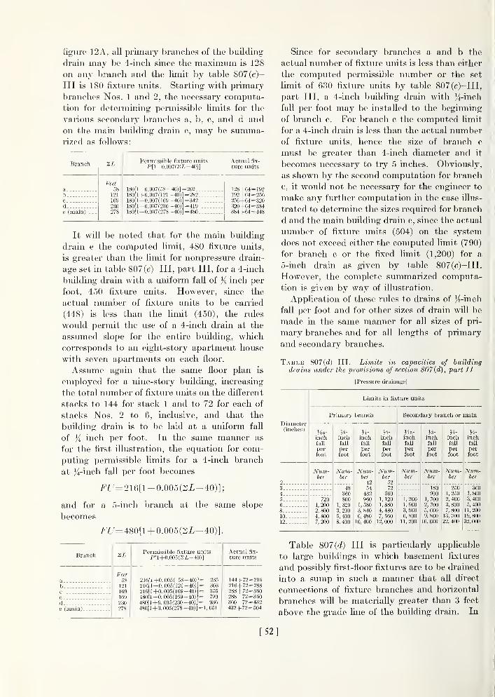
figaire 12A, all primary branches of the building
drain may be 4-inch since the maximum is 128
on any bi'anch and the limit by table 807(c)-
III is 180 fixture units. Starting with primary
branches Nos. 1 and 2, the necessary computa-
tion for determining permissible limits for the
various secondary branches a, b, c, and d and
on the main building drain e, may be summa-rized as follows:
Branch 2£ Permissible fi.xture unitsP[1+0.007(2L-40)]
Actual fix-
ture units
a.b0
de (main)
Feet58
121
169230278
180[1+0.007(58-40)] = 202180[1+0.007(121-40)] = 282
180[ 1 +0.007(169-40)] = 342180[l+0.007(230- 40)] = 419180[l+0.007(278-40)] = 480
128+64 = 192192+04 = 256256+64 = 320320+64 = 384384+64= 448
It will be noted that for the main building
drain e the computed limit, 480 fixture units,
is greater than the limit for nonpressure drain-
age set in table 807(c)-III, part III, for a 4-inch
building drain with a uniform fall of }g inch per
foot, 450 fixture units. However, since the
actual number of fixture units to be carried
(448) is less than the limit (450), the rules
would permit the use of a 4-inch drain at the
assumed slope for the entire building, which
corresponds to an eight-story apartment house
with seven apartments on each floor.
Assume again that the same floor plan is
employed for a nine-story building, increasing
the total number of fixture units on the difi^erent
stacks to 144 for stack 1 and to 72 for each of
stacks Nos. 2 to 6, inclusive, and that the
building drain is to be laid at a uniform fall
of /4 inch per foot. In the same manner as
for the first illustration, the equation for com-
puting permissible limits for a 4-inch branch
at }^!-inch fall per foot becomes
Ff'= 216[l + 0.005(2Z-40)];
and for a 5-inch branch at the same slope
becomes
irL'= 480[l +0.005(2L^40)].
Branch
bc
cde (main)
Si
Feet58
121
169169230278
Permissible fixture unitsP[l+0.005(2i-40)]
216ri+0.005 ( 68-40))= 235
216[1 +0.005(121-40)]= 303
210fl +0. 005(169-40)] = 355
480[1 +0.005(169-40)]= 790
480[l+0. 005(230- 40)]= 936
480fl+0. 005(278- 40)] = 1, 051
Actual fix-
ture units
144+72=216216+72=288288+72=360288+72= 360360+72= 432432+72=504
Since for secondary branches a and b the
actual number of fixture units is less than either
the computed permissible number or the set
limit of 630 fixture units by table 807(c)-III,
part III, a 4-inch building drain with }{-inch
fall per foot may be installed to the beginning
of branch c. For branch c the computed limit
for a 4-inch drain is less than the actual numberof fixture units, hence the size of branch c
must be greater than 4-inch diameter and it
becomes necessary to try 5 inches. Obviously,
as shown by the second computation for branch
c, it would not be necessary for the engineer to
make any further computation in the case illus-
trated to determine the sizes required for branch
d and the main building drain e, since the actual
number of fixture units (504) on the system
does not exceed either the computed limit (790)
for branch c or the fixed limit (1,200) for a
5-inch drain as given by table 807(c)-III.
However, the complete summarized computa-
tion is given by way of illustration.
Application of these rules to drains of K-inch
fall per foot and for other sizes of drain will be
made in the same manner for all sizes of pri-
mary branches and for all lengths of primary
and secondary branches.
Table 807(d)-III.
—
Limits in capacities of building
drains under the provisions of section 807 (d), part II
[Pressure drainage]
Diameter(inches)
Limits in fixture units
Primary branch
He-inchtall
perfoot
Num-ber
7201,2002,8004,8007,200
inchfall
perfoot
Num-ber
48360800
1,3203,2005, 4008, 400
inchfall
perfoot
Num-ber
4254
432960
1, .580
3, 840
6, 48010, 400
inchfall
perfoot
Num-ber
5272
5001, 1201, 8804, 480
7, 56012, 000
Secondary branch or main
/16-
inchfall
perfoot
Num-ber
1,2001,9003, 9006, 800
11, 200
inchfall
perfoot
Num-ber
180900
1,7002, 7005,6009, 800
16, 000
H-inchfall
perfoot
Num-ber
2501,2502,4003, 8007,800
13, 70022, 400
H-inohfall
perfoot
Num-ber
3601,800
3, 4005, 40011,200
19, 80032, 000
Table 807(rf)-III is particularly applicable
to large buildings in which basement fixtures
and possibly first-floor fixtures are to be drained
into a sump in such a manner that all direct
connections of fixture branches and horizontal
branches will be materially greater than 3 feet
above the grade line of the building drain. In
[52]

computing the permissible limits for particular
systems xmder the rules (which see) applying
to pressiire draiuag-e, both sections 807(c) and
807 (d), part II, apply.
Rnles for Apph/ivg Section S07(d), Port IT, (ind
Table 807 {d) III, Part III
1. Lay out the building plan to scale as for the
application of section 807(c), part II (see
fig. 12B), and scale off the developed lengths
of each primary and secondary branch.
2. For each stack in the system, determine the
elevation of the lowest horizontal branch
above the grade line of the building drain.
3. Scale off the developed length of pipe from
the intersection, B, of the branch with the
building drain to the lowest horizontal branch
connection to the stack farthest upstream.
Also, determine the developed length from Bto the lowest horizontal branch on each of
the other soil and waste stacks.
4. Lay off to a convenient scale a horizontal
line {BiB in fig. 12C) equal to or greater than
the greatest developed length obtained byapplying rule 3. Also, lay off in order on line
BiB from point B aU other developed lengths
as obtained by the application of rule 3 anddesignate the points on line BiB as B2, -63,
etc. At each of the points Bi, Bo, B3, etc.,
erect lines perpendicular to BiB. Also, on
hne BiB, or on BiB extended if necessary,
lay off a length BJ equal to that in which a
total fall of 1 foot would be given for the
slope involved and erect the perpendicular
hnejf/' equal to 1 foot and draw the straight
hne Bf to intersect the perpendicular line
from Bi. Designate the intersection as i.
Then on each of the perpendicular lines from
Bi, B2, B3, etc., lay off lengths from the line
Bf equal to the elevation of the lowest
branches on each of the corresponding stacks
above the grade line and designate the
resultant points as Si, S2, S3, etc. Thendraw a straight line from point B such that
at least one of the points Si, S2, S3, etc., lies
on the line and none of them lie below it.
Extend the line to intersect the vertical line
from point Bi, which intersection (designated
as 7) may be at or below point Si, depending
on the relative elevations of the lowest
braucbes on tli(! dilfci'ent stacks involved.
Scale off the lengths Bil and Bii.
5. Select a value P from table 807(c)-in, part
III, for pi'iriiiiiv branches corresjjondinjr to
the sloj)!' i)f I he (Iriiin such that the pi-odiici
PyjBJlAB{i is to or greater tlian the
numbei- of fixture units to be carried by a
primary branch and that the cori-('S|)()nding
product Pi-^BJ/4Bii for the next smaller
size is less than the numl)er of fixtui-e luiits
to be carried by tlie primary bj-ancli in (|ues-
tion. The larger of the two sizes will be
the minimum permissible size for the pii-
mary branch in the particular case, provided
that both the product P^jB^lWBj and the
limit for a primary brancli of that diameter
in table 807((i)-III, part III, are each equal
to or greater than the number of fixture units
actually carried.
6. To obtain the permissible load limits for
secondary branches and the main building
drain of the particular system, proceed as byrule 8 applying to section 807(c), part II,
starting in each case with the computed lim-
its for primary branches as given by rule
5 above instead of the limits given in table
807(c)-III, part III.
7. If the slope of the buildmg sewer is equal to
or greater than the slope of the main building
drain, it may be of the same nominal diameter
as the main building drain arrived at by the
application of the preceding ride 6. If at anypoint the slope of either the mam building
dram or the building sewer is decreased, the
drain laid at the lower slope shall be mcreased
in diameter, if necessary, so that its limit in
capacity by table 807(f/)-III, part III, at
the slope laid, is equal to or greater than
the load to be carried.
Illustration of Application of Rules for Pressure
Drainage
For this ilhistration, assume that the building
has a base area 60 by 100 feet, as illustrated in
figure 12B; is 20 stories high; and wiU contain
fixtures that total 3,528 miits, distributed
among four stacks, and a sump located as indi-
cated in the figure. In this illustration, the
drain from the sump pump, entering- the mainbuilding drain at pomt B, is the last branch.
[53]

Now assume that the elevation above grade
line of the lowest branch connected to each of
the stacks is as follows: Stack 1, 14 feet; stack
2, 9 feet; stack 3, 10 feet; and stack 4, 9 feet;
and that the slope of the building drain is
'/8-inch fall per foot. The developed length of
drain from B to the lowest branch on stack 1 is
5+14+14+ 30+ 28+ 14= 105 feet. We nowhave the data for the scale laying out figure 12C
as prescribed by rules 3 and 4. From the figure,
i5i7=13.8 feet and 5,/= 1.1 feet; from which
^jBJlABii = V13.8/4.4 = 1 .77, the factor bywhich the limits foi' primary branches as given
in table 807(c)-III, part III, are to be multiplied
to determine the allowable loads within the
limits for primary branches by table 807(rf)-III,
part III, for the particular building and condi-
tions assumed. Ordinarily, the required mini-
mum size of a primary branch can be predicted
by comparing the permissible loads for pressure
drainage, table 807(c^)-III, and the number of
fixture units to be carried in the case at hand
without going through the details of computa-
tion prescribed in rule 4. For example, in the
present illustration the basic size for computing
secondary branches will obviously be deter-
mined by the primary branch from stack 2, and
the load, in this case 1,880 fixture units, lies
between the permissible load of 1,320 fixture
units for a 6-inch primary branch with }^-inch
fall per foot by table 807(r/)-III, and the hmit
in load, 3,200 fixture units, for an 8-inch pri-
mary branch at that slope. Hence, the sec-
ondary branch must be at least an 8-inch pipe
and the trial computation becomes
1.77X1,600= 2,832 fixture units.
Since 2,832 fixtm'e imits is less than the limit
(table 807(r/)-III) for an 8-inch primary branch
of }s-inch fall per foot under j^ressure, and
greater than the actual number (1,880), the
size required for the primary branch from
stack 2 is 8-incli diameter.
Similarly, for stacks 1, 3, and 4, the limits
lor a 5-inch primary branch at ^g-inch fall per
foot are 400 fixture units for nonpressure drain-
age (table 807 (c) III) and 800 fixture units
for pressure drainage (table 807 (rf)-III).
Again, 1.77 X 400= 708 fixture units is greater
than the load to be carried (480 fixture
units) and less than the limit (800 fixture
units) for pressure drainage, and hence a5-inch primary branch will be required fromstacks 1, 3, and 4. Starting with stacks 1
and 3 and applying rule 5 for pressure
drainage, page 53, and then rule 8 for nonpres-sure drainage, page 49, the computation maybe summarized as shown in the following table.
In this case there will be three different values »
of P (the permissible number of fixture units onthe primary branch) to be used in the equation,
F[7=P[l+a(2i-40)]; Pi= 708 fixture units,\
applying to the secondary branch a for stacks '
1 and 3; ^0= 1.77 X660= 1,168 fixture units,[
applying to the secondary branch b for stacks
1, 3, and 4; and P3= 1-77 X 1,600= 2,832 fixture
units, applying to the primary branch fromstack 2, to the secondary branch c, and to the
main building drain d.
Branch 2iPermissible fixture units
P[l+0.007(2i-40)]Actualfixture
units
Diam-eter re-
quired
Feet Inchesa-
.
86 708(1+0.007(86 -40)]= 935 960 6b 130 1, 168[1 +0. 007(130 -40) ] = 1 , 904 1,440 6c 190 2, 832(1+0. 007(190-40)1 = 5, 805 3, 320 8d (main) .
.
219 2. 832(1+0. 007(219-40)1= 6, 380 3, 528 8
Summarizing, the requirements in sizes are
as follows:
5-inch for primary branches from stacks 1,
3, and 4;
8-inch for primary branches from stack 2;
6-inch for secondary branches a and b;
8-inch for secondary branch c; and8-inch for main building drain d.
Since the number of fixture units carried bythe main building drain and building sewer
(3,320 + 208= 3,528 fixture units) does not ex-
ceed either the ultimate limit (5,600) for an 8-
inch drain or the computed limit (5,805) for the
secondary branch c immediately upstream from
the junction point B, the main building drain
d and the l)uilding sewer may also be 8-incli
pipe if they are laid with not less than }^-inch
fall per foot. It should be noted that the com-
puted limit may sometimes exceed the ultimate
permissible limit given by table 807(('/)-III,
part III, as is the case in the computation for
branch c. In these cases, the permissible limit
in the table shall apply.
Par. 902. Gutters and Leader Connec-
[54]

TiONS.—Roof gutters are not ordiiuirily con-
sidered a part of the plumbing work and are
usually installed under a separate contract and
bv different workmen. However, the require-
ments for and installation of roof gutters are
related to the plumbing in that they are the
principal collectors of storm water and are
directly connected to the leaders of the Storm-
drainage system of the building. Hence, the
capacities of roof gutters and their outlets to
leaders should be consistent with the capacities
of the leadei'S. The following information is
included here as an aid to the engineer in
specifying the proper sizes of roof gutters and
outlets.
Table 902-IJI.—Maximum roof area for semicircular
rooj gutters with a fall of yie inch per foot or less
Diameter of Maximumgutter roof area
Inches Square feet
3 170
4 3605 625
6
7
9601,380
8 1, 99010 3,60012 6,800
The capacities in the preceding table are
based on the flow capacities of gutters of semi-
circular sections, no slope, one outlet, and a
rate of rainfall of 4 inches per hour. If the
faU is greater than inch per foot or if the
gutter has two or more outlets (leaders), the
permissible roof area as given in table 902-III
may be increased by multiplying it by one or
both of the following factors as they apply:
(a) by -y/sj {1/16), where s is the actual fall in
inches per foot; and (b) by n, the ninnber of
outlets, provided the roof area drained into
any one leader does not exceed the value given
in table 902-III or the permissible roof area as
computed by (a). For example, assimie that a
3-inch semicircular roof gutter is pitched with
a fall of }i inch per foot so as to divide the roof
area equally between two leaders. The per-
missible roof area on the 3-inch gutter becomes
170^^X2= 340V2= 479 sq ft.
For roof gutters with rectangidar or other
polygon-shaped cross-sections, table 902-III
in ay be used safely, provided the gutter has a
depth ('<|ual to the I'adiiis jmd iiii average uidlli
equal to the diameter of tiie semicircular sec-
tion; or the capacity of a roof gutter of any
shape may be safely assumed as equal to tliat
of a semicircular gutter equal in radius to that
of the largest semicircle that can be insci-ibcd
wholly within the cross-section of the gutter
in question.
Roof aiT'a for application to requirements for
roof guttei's will be computed in the same man-ner as for storm drains. (See sec. 903(c), pt.
II.)
The capacities of roof gutters as given in
table 902-III, part IH, assume an outlet of at
least equal capacity. Insufficient outlet through
the leader connection, improperly formed leader
outlet and strainer, and clogged strainer or
leader connection are the usual causes of an
overflowing roof gutter, except in cases of
rainfall in excess of the rates provided for.
There are no generally recognized standards
governing the forms and sizes of leader con-
nections. The outlet of a roof gutter flowing
at capacity should be at least equal in cross-
section to the gutter. Likewise, the total
intake area of the strainer should be at least
equal to the cross-section of the gutter. Therequired intake area may be obtained by dom-ing the strainer or by increasing the dimensions
of the strainer and leader connection.
Par. 903. Size of Storm Drains and Lead-ers.—Tables 903(6) and 903(c), part II, are,
as stated, based on a rate of rainfall of 4 inches
per hour. Whether it is essential to makeallowances for greater rates of rainfall in certain
localities wiU depend on the maximmn rates and
frequency of rates higher than 4 inches per
hour of rainfall recorded for these localities and
to some extent on whether any particular
damage to health or property would result from
overflow. Likewise, whether it is advisable to
increase the allowable load on leaders and storm
drains of given diameters and slopes will de-
pend on the weather records and on whatmaximum rate of rainfall is to be expected. In
either case, the tables given can be utilized for
detennining the size of pipe needed by simply
multiplying the allowable roof areas as given
in the tables by ~> where x is the rate of rainfall' X
to be provided for. For example, if a rate of
[55]

only 2 inches per hour is to be provided for, the
allowable roof areas may be doubled; and if a
rate of 6 inches per hour is to be provided for,
the allowable roof area would become 2/3 of
the values given in the tables.
Par. 903(d). Allowance for ProjectingWalls.—In case a wall projects above a roof
in such a manner that storm water drains from
the wall onto the roof, the following allowances
to be added to the roof area are suggested:
(1) For total roof area applied to a leader or
storm drain receiving total flow from the roof:
a. For one wall only, add 50 percent of the
wall area;
b. For two adjacent walls only, add 35 per-
cent of the sum of the wall areas if both are of
the same height. If the two adjacent walls are
of different heights, allow 35 percent of the
combined wall area below and 50 percent of the
waU area above the top of the lower wall
;
c. For two opposite walls only, make no
allowance if both are of the same height. Add50 percent of the wall area extending above the
lower wall if the two are of dift'erent heights;
d. For walls on tkree sides, add 50 percent
of the area of that part of the inner wall that
lies below the lowest of the three walls, and
allow for the portions of the two walls extending
above the lowest, as in b if the walls are adja-
cent, or as in c if the walls are opposite;
e. For walls on four sides, ignore all wall areas
lying below the top of the lowest wall, and add
for those extending above it according to
whether they fall under a, b, or d.
(2) For api^lication to leaders or storm drains
receiving only part of the roof drainage:
a. Determine the portion and dimensions
of the roof area drained into each leader
connection;
b. Compute allowance for projecting walls
separately for each leader connection, as for
total allowance to be added, ignoring walls not
directly adjoining and extending above the
section of the roof drained into the leader for
which the computation is being made.
(3) For application to the main building drain
and building sewer:
a. Ignore walls not extending above the
building;
b. For one wall only extending above the
building, ignore the wall area if it is less than
that of the roof, or add 50 percent of the differ-
ence if it is greater than the roof area;
c. For two adjacent walls only, ignore the
combined wall area if less than that of the roof,
or add 35 percent of the difference if it is greater
than the roof area;
d. For two opposite walls only, ignore wall
area if the area of that portion of the higher
wall above the top of the lower is less than the
roof area, or add 50 percent of the dift'erence
if it is greater;
e. For three walls extending above the build-
ing, ignore wall area below the top of the lowest
wall and then apply c or d above according to
whether the walls extending higher are adjacent
or opposite.
In all cases, the importance of applying an
allowance for walls extending above the building
and draining onto its roof depends largely on the
relative areas of the extending walls and the
roof. If the roof area is large relative to the
total area or to that part of the total area for
which allowance would be made under the
preceding rules, the matter is not likely to be of
great importance. It may be very important
to make an allowance for wall area if a low
building is built at the side of a tall one or into
an angle formed by two tall buildings, or if a
low-roofed portion of a building has a similar
relation to dift'erent wings. It will be of less
importance in any case if the leaders and storm
drains required by the regulations for roof area
alone are more than ample than if they are near
the limit in capacity.
The allowances given in the preceding rules
were selected to provide for a driving rain at an
angle of 30° with the vertical. Regardless of
the angle at which the rain falls, the portions of
projecting roofs ignored under the rules given
can be safely ignored in regard to their eft'ects
on the building storm sewer.
Par. 904. Separate and Combined Drains.—The provisions of section 904(a), part II, are
intended to require separate sanitary and storm
systems until they can be conveniently con-
nected at grade. The sanitary system should
be collected into one sanitary drain and the
storm system into one storm drain, and the two
connected at grade, if it can be conveniently
done without crossing over. If the preceding
[56]

is not convenient or economical, the sanitary
and storm drains on each side of the combinedsewer of the building may be joined at grade as
described and the two combined drains thus
formed connected to the building sewer. Con-nections should not be made through double-
wye hi-iiiiclics. If the street S(!Wer is siiljjcci
to overcharging or submergence, tliere \\ ill he
less likelihood of detrimental efl'ects to tiie
sanitary system if the storm (li iiinage and sani-
tary drainage are carricid sepai'ately to tlie
street sewer.
Table 904-III.
—
Required diameters for combined building drains and sewers according In number of fixture units
FOR DRAINS AND SEWERS HAVING ).ii-INCH FALL PER FOOT
^\ Fixture\ units
\Roofarea
0...775..--
1,350.-1,550..
2,100..2,700..4,200..4,350..
7,600-.8,700. -
12,400-
15,200-
24,800-
225 425 450 675 850 1,350 1,400 2,450 2,800 4.000 4,900 8,000
. in. in. in. in. in. in. in. in. in. in. in. in.4 4 4 5 5 6 8 8 8 10 10 12
4 4 0 5 6 6 8 8 8 10 10 10 124 5 5 6 6 6 8 8 10 10 10 10 124 5 6 6 6 8 8 8 10 1(1 10 12 125 6 6 6 6 8 8 8 10 10 10 12 125 6 6 6 8 8 8 8 10 10 12 12 126 8 8 8 8 8 8 S 10 1(1 12 12 128 8 8 8 8 8 8 8 10 10 12 12 158 8 10 10 10 10 10 10 10 12 12 12 158 8 10 10 10 10 10 10 12 12 12 12 1510 10 10 10 10 10 12 12 12 12 12 15 1510 12 12 12 12 12 12 12 12 15 15 15 1512 12 12 12 12 12 12 12 15 15 15 15 15
FOR DRAINS AND SEWERS HAVING J4-INCH FALL PER FOOT
\^ Fixture\ units
\Roof \area \
\
0 315 595 630 950 1,190 1,900 1,950 3,400 3,900 5,650 6,800 11.300
sqft in. in. in. in. in. in. in. in. in. in. in. in. in.
0 4 4 4 5 5 6
8
8 8 8 10 10 121,075 4 4 5 5 6 6 8 8 10 10 12 121,800 4 5 5 6 6 6 8 8 10 10 10 12 122,150 4 5 6 6 6 8 8 8 10 10 10 12 123,000 5 6 6 6 6 8 8 8 10 10 10 12 123,600 5 6 6 6 8 8 8 8 10 10 12 12 155,950 6 6 8 8 8 8 8 8 10 10 12 12 156,000 6 8 8 8 8 8 8 10 10 10 12 12 159,800 8 8 8 8 10 10 10 10 10 12 12 12 15
11,900 8 10 10 10 10 10 10 10 12 12 12 12 15
15,900 10 10 10 10 10 10 12 12 12 12 12 15 1519,600 10 10 12 12 12 12 12 12 12 12 15 15 1531,800 12 12 12 12 12 15 15 15 15 15 15 15 15
FOR DRAINS AND SEWERS HAVING ^-INCH FALL PER FOOT
^\ Fixture
\^ units
\Roof \area \^
0 450 850 900 1,350 1,700 2,700 2,800 4,900 5,600 7,500 9,800 15,000
89 /(
0
in. in.
4
in.
4
in.
4
in.
5
in.
5
in.
6
in.
8
in.
8
in.
8
in.
10
in.
10
in.
12
1,550 4 4 5 5 6 6 8 8 8 8 10 10 12
2,700 4 5 5 6 6 8 8 8 10 10 10 10 12
3,100 4 5 6 6 6 8 8 8 10 10 10 12 12
4,200 5 6 6 6 6 8 8 8 10 10 10 12 12
5,400 5 6 6 6 8 8 8 8 10 10 10 12 15
8,400 6 8 8 8 8 8 8 8 10 10 12 12 15
8,700 8 8 8 8 8 8 8 8 10 10 12 12 15
15,200 8 8 10 10 10 10 10 10 10 12 12 12 15
17,400 8 10 10 10 10 10 10 10 12 12 12 15 15
24,700 10 10 10 10 10 10 12 12 12 12 12 15 15
30,400 10 10 10 12 12 12 12 12 12 12 15 15 15
49,400 12 12 12 12 12 15 15 15 15 15 15 IS 15
[57]

-vent
'fixture drain
a, not less than 2orgreater than
48 diameters
h, notgreater t/ian ore d/ameter
-dra/n
Figure 13.
—
Distance of trap from vent.
Par. 1002. Protection of Trap Seals.—The requirements of chapter X, part II, are
designed to give the maximum flexibihty in the
design of a building-drainage and venting
system consistent with an adeqiiate protection
of the seals of fixture traps. This flexibility is
accomplished by a more complete classification
of vents as to their functions, locations, and
forms, and a more detailed statement of the
limits of use of different forms than is to be
found in the usual plvimbing code.
Par. 1005. Distance of Trap From Vent.—Section 1005, part II, applies particularly to
vents for separate traps, usually termed "back
vents." The most effective point for venting a
fixture drain depends on the form of the drain.
If the fixture drain turns to the vertical within
48 pipe diameters from the trap weir, a vertical
continuous-waste-and-vent at that point is the
most effective vent that can be installed. If
the fixture drain slopes continuously from the
trap weir, the requirement, assuming a fall of
}^ inch per foot, limits the pei'missible length of
drain between trap and vent to: 5 feet for a
l}^-inch di-ain; 6 feet for a l}^-inch drain;
8 feet for a 2-inch drain; and 12 feet for a 3-inch
drain. If a fixture drain connects with an
adequate relief vent or with a stack-vent within
these limits, the relief vent or stack-vent will
perform the functions of a back vent. (See
fig. 13.)
Par. 1008. Yoke and Relief Vents.—Sec-
tion 1008, part II, gives the details and neces-
sary restrictions for group venting the plumbing
fixtures, ordinarily installed in residences, bymeans of a stack-vent, yoke vents, or relief
vents. The application of section 1008 in con-
junction with sections 1005 to 1007 makes manysimplifications in piping possible and offei^s
inviting opportunities for standardization and
pi'efabrication. Figures 16 to 20 illustrate a
few simplified lay-outs for residential construc-
tion wliich may be varied to a considerable
extent in arrangement of fixtures without con-
flicting in any respect with the minimumrequirements of tliis manual.
Figure 16 illustrates the simplest lay-out, and
in general the most effective venting obtainable,
for a single bathroom group and a kitchen sink
or combination fixture all in one story or branch
interval. The figure illustrates one arrange-
ment of the fixtures about the stack, and illus-
trates the type of fittings required. The line
sketches of figures 17 to 20 merely indicate
typical drain lay-outs and venting required
under section 1008 for these lay-outs.
The group venting illustrated in figure 16
may be used on a yoke-vented section of a
horizontal branch not less than 3 inches in diam-
eter, in any branch interval of a soil stack, and
the order of the fixtures around the stack or
yoke-vented branch may be varied as necessary
dual vent
-I \/ 7-
-fixture drain
-drair?
— dual vent
not greater ftfan
5 diameters
Figure 14.
—
Dual vents.
[58]

back vent-
vent
dualback ventp-
-drain
vent
daafback vent
- drain
8Figure 15.
—
Group vents for lavatories and bathtubs.
c
for accommodation to the floor plans of any
particular building.
Figure 17 illustrates essential venting for a
two-story lay-out with kitchen sink on the first
floor and bathroom group on the second floor.
Figure 18 illustrates two lay-outs for duplex
construction as permitted by section 1008(c).
The lay-out for lavatories and bathtubs illus-
trated in the lowest branch interval of figure 20
may be used in lieu of that illustrated in figure
18B.
Figure 19 illustrates the permissible lay-out
under section 1008(6) for two bathroom groups
and two kitchen sinks in the two highest stories
or branch intervals of a building. Alternate
connections for the sinks are shown in dotted
lines with the vents required in case the sinks
are connected to a separate stack or to the soil
stack below the highest water-closet branch.
Figure 20 illustrates permissible lay-outs for
duplex construction for any number of floors or
branch intervals for fixtures of the same kind
located back-to-back. If the fixtures are not
located back-to-back, the lay-out represented
in figure 18A may be installed in any branch
interval with relief vents of the yoke-vent type
as shown in figure 20.
Figures 13 to 20 illustrate the main essentials
for eft'ective group venting and may be used in
any combination so long as these essentials are
preserved. Under section 1008((^), any numberof the fittings and the pipe necessary to make the
installations illustrated in figures 13 to 20 or
permitted by the requirements of part II mnybe standardized for particidar or typical floor
plans and cast in one fitting or otherwise pre-
fabricated.
Ve/?/ at least
12"above roof
Kitchen 5/nkt/z Trap
Tapped 3on/tory
bath
lii'Trap"^
^Floor
Water_ Closet bend
5Long 3weep bend'
Figure 16.
—
Stack-vented piping lay-out for orie-siory
house.
[59]

^ -stack- vent
Figure 17.
—
Piping lay-out for two-story house iviih one
bathroom.
Par. 1010. Vents fok Flat-Bottomed Fix-
tures.—Section 1010, part II, is intended to
apply particularly to installations for kitchen
sinks and to provide for more effective drainage
of the fixture and scouring of the fixture drain
than can be obtained in some cases by an instal-
lation back-vented near the trap.
Clogging of the fixture drains of kitchen
sinks by deposits from greasy waste water is a
source of annoyance and a cause of frequent
servicing. In this connection it should be
noted that, in general, the shorter and the more
direct the fixture drain is, from the trap to its
connection to a stack or to another drain that is
thorouglily washed by the discharge from other
fixtures, the more effective the drainage will be
in respect to both quickness of emptying of the
fixture and freedom from clogging. However,
the location of the kitchen relative to stacks or
drains that are thoroughly washed by other
fixtures may make it necessary to install a
fixture drain from the sink with a relatively long
sloping section. The installation of a back vent
on the fixture side of the sloping section of the
fixture drain wUl reduce the effective head on
the drain, result in sluggish action, and induce
deposition which will usually result in clogging
both the fixture drain and back vent. Omission
of the vent will ordinarily provide more effec-
tive drainage which, in some cases, m^ij be
noisier in operation than if the back vent were
installed. Section 1010, part II, simply gives
the buUder a wider latitude in designing for
effective and safe operation of sink installations
than is given in section 1005, part II. (See
fig. 23.)
Par. 1011. Vents for Resealixg Traps.—Section 1011, part II, is intended to provide for
cases where no space is available for a properly
installed vent for a P-trap. A group of lava-
tories located in the middle of a washroom floor
would be an example of such a case.
Par. 1012. Fixtures at Base of MainVent.—The purpose of the provisions of sec-
tion 1012, part II, is to permit the installation
of a limited nimiber of fixtures at the base of
Figure 18.
—
Piping lay-out for one-story duplex house.
60

long vertical vents to wash out nist or other
products of corrosion. Fixtures discharging
greasy or other waste water likelv to congeal
and deposit and fixtures in excess of the limits
set in section 1012 should not be so connected.
Par. 1101. Indirect Connections.—Any in-
du'ect connection whereby the continuity of the
- shcM- vent
; -x-a/fernafe h/ouf fors/nkj /
Figure 19.
—
Piping lay-out for bathrooms in each of two
stories.
-stack- vert
alferm/e for lowrormtermed/ategroup
Figure 20.
—
Piping lay-out for duplex apartments.
\ Stack Vent
Vent
Circuit Vent
V \\ Soil5tack Branch Vent
Relief Vent
Vent5tack
Figure 21.
—
Illustration of circuit-and-loop vents.
_J I
/?oof
h \Note: Vent 5tac/<: may loop
]
fo Stack Vent or extenddirect/y thru roof
5tacli Vent c H
W.C- \w.c.
- Relief Wnt^ I
^ ^ ^ ^
Soil Stack
\Rdiefknt^^ Circuit Vent-
a floor
b Floor
Vent Stack
c Floor
d Floor
a Top floor without relief
b Intermediate floor triftj one relief /e/?f
c Intermediafe or lower floor tvitti two
rel/ef ye/?ts
d Intermediate or lower floor for
double line of ffiturej
Figure 22.
—
Limits for circuit-and-loop vents.
[61]

—venfu
,1u
a, nof more than 10 d/amefers
b. nof more fhan^^ diameters
a*c. not more than 7£ diameters
Figure 23.
—
Drains and vents for Jlat-ltotUnncd fixtures.
waste line from an appliance, device, or appa-
ratus having a diip or drainage outlet is broken
by an air gap of such spacing as will prevent
backflow, is approved if the waste water is not
contaminated with human or household wastes
and if the waste line discharges on the inlet side
of a fixture trap. Such fixture trap may be a
part of the plumbing installation of the appli-
ance, device, or apparatus, or it may be the
trap of a regular plumbing fixture. In the
latter case the air gap should be above the flow
line of the fixture.
Appliances, devices, or apparatus where such
indirect connections are required are stills,
sterilizers, equipment requiring cooling water,
and the like. Examples of such indirect con-
nections are shown in ftgure 24.
Par. 1305(6). Air Tests.—In applying air
tests, it shoidd be noted tliat a slowly falling
pi'cssure is not necessai'ily an indication of a
leaking system. If the air introduced is of a
higher temperatiu-e than that of the piping
system or than that of the air already in the
system, the pri'ssure will fall slowly until tem-
perature equilibriimi is reached. In such cases,
before searching for definite leaks, the pressure
should again be brought to the test value with-
out changing the air in the system. If the rate
of fall is materially lower on the second or on
repeated trials, it may be taken as an indication
of a tight system. On the other hand, if the
temperature of the air introduced is lower than
that of the piping system or the air already in
the system, a slowly rising pressure may occur.
A rising pressure or constant pressure for a 15-
minute period may be taken as a positive
indication of tightness. In case of a rapidly
falling pressure, a search for leaks should be
made before repeating. The same precautions
apply to smoke tests.
^\Jlir dap nof Ifss
than iw/ce effec-
five opening
Fixed ^I'r break
Figure 24.
—
Indirect wastes.
[62]

INDEX
A PageAccepted standards ._ 27
Definition GAccessibility:
Offixtures for cleaning 14Of indirect-waste connections 22Of overflow pipes for cleaning 14Of sand interceptors 13Of traps and olcan-outs_._ 13
Acid wastes 46Adjacent buildings, relation of vent terminals to 22Adjustments after test 24Affidavit for plumber's test 23Air gap 34, Gl
Definition ; 6Illustration of 34
Air-pressure test:
Of drainage system 23Of sanitary-drainage system 23Of vent system _ 23Of water-supply system 23
Air test, final 23Air tests 62
Of defective plumbing 24Of drainage system 23Of leaders 24Of roof connections 24Pressure in 23, 24Time required for 23, 24
Alterations , considered as new work 24
Alternate materials 11
American Society for Testing Materials 29American Standards Association 29Ample flow, definition 35Apartment houses, water-demand estimates for small 44
Application of flow charts 40Approval:
Before covering work 24Certificate of 24
Of alternate materials 11
Of plans for building drain 16
Of plans for building sewer. _ IG
Of plans for drainage svstem 16
Written, of tests 24
Approved, definition 6Aquaria _ 14
Area drain:Definition G
Trap, need not be vented... 22
B
Back siphonage, definition. See Backflow.Back vent 58
Definition.. li
Distance from trap weir 22
For flat-bottomed fixtures 20Location of 18
On fixture drain of kitchen sink GOProhibited 22Size of 21
Backflow:Definition _. _ 6
Protection against - -- 13,14, 34
Backflow connection:Definition 6
Prohibited 9
Backflow preventers 34
Back-pressure valve for subsoil drain 18
Backwater, protection of subsoil drain against 18
Backwater traps, need not be vented 22
Backwater valves 13
Baptistries 14
Bar sinks, small, size of trap and drain for _-_ 12
Barns used for human habitation _. 24
Basement drain trap, need not be vented 22
Bath fillers, air gaps for 34
Bathroom group:Private, fixture-unit value of 15, 40
Venting of 19
Bathrooms, water-demand estimates for 44
Bathtub:Group vents for 59
Private, fixture-unit value of 15, 40
Public, fixture-unit value of 15, 40
Size of supply outlets for 14
Size of trap and drain for 12
Trap, venting of 19
Battery: PageCircuit and loop venting of 20Double, circuit and loop venting of "III."""'"'' 20
Blow-offs, connections of 22Boiler blow-ofTs, connections of 22Branch:
Definition _ gFixture, definition ""I"'"'"!'" 7Sanitary, of combined drain size of _
" 17Storm, of combined drain, size of 17To heater, required sizes of if.
Yoke-vented, independent connections with 10See also Fixture branch; Horizontal branch; Hot-water branch;Primary hriiiiches; Secondary branches.
Branch iiilcr\ ;il, <lcflnition 6Branch veiil,, ilulinition gBrass:
Calking ferrules _ 11 31Fittings 11' 31Pipe _._ lojaoJheet — - 11,31lubmg.... _ 10,30
Buildm!.' dram:Capacity of 16,57Capacity of branches ig( '(iiripnting capacity of 49, 52, ,54
I >('fliiil . ' gMaterial of underground 14Xonpressure drainage, fixture-unit value of 49Pressure drainage, fixture-unit value of 52Separate tests of 24Size of 16,54Size of, for given roof area 57Submittal of plans for ig
Building-drainage system, definition 6Building line, relation of vent terminals to 22Building main:
Definition 6Fixture units and estimated demands on 44For .small buildings 43Required sizes of . 45Size of 13, 35, 44Sui)ply required for 44Velocity of supply of 44
Building sewer:Capacity of 16Definition 6Fixture-unit capacity of 57A'lalerial of_ _ 14Separate tests of 24Size of 16, 54Size of, for given roof area 57Submittal of plans for 16
Building subdrain;Definition 6
Discharge of 16Building water main, estimating for continuous demands on._ 42Bureau of Standards, National 29,45Bushings, soldering 11
CCalked joints 11
Calking:Ferrules 11,31
Lead 10,31Not acceptable in repairs 24
Of vent terminals 22
Cast iron:
And other piping, joints between 11
Fittings 11,31
Pipe joints 11
Screwed pipe 10,30
Soil pipe 10. 29
Water iiipe 10.29
Catcliliiisiii trap, subsoil, need not be vented 22
Cellar-lldor drain trap, need not be vented 22
Cement joints in vitrified-clay pipe 32
Cenioiitod joints UCertificate uf approval 24
Cesspool, leaching, definition 27
Cesspools 27
Changes in direction 9
Changes in size of pipe... 12,32
Chemical mixtures, use of, prohibited in tests 24
Chemical wastes 46
Circuit-and-loop venting, limits of 20, 61
Circuit-and-loop vents, illustration of. 61
[63]

PageCircuit vent 20
Definition fi
Size of 21Cisterns:
Overflow pipes from 18Protection from freezing 13
Clay pipe:Joints-.. 11,31Vitrified 10,29
Clean-out equivalents 13Clean-outs:
Accessibility 13
For refrigerator wastes 22Pipe 13
Pipe, location of 13
Pijje, size of 13
Trap 13
Traps and 12Clogging of sinli; drains 60Closed system required 18Closets, frostproof 14
Closing of openings in tests 23, 24
Combination fixture:
Definition _ _ : 6
Size of trap and drain for 12
Combination kitchen sink and tray, venting of 19
Combination sink and laundry tray, private, fixture-unit value of.. 15
Combined drains 17,56Size of 17, 57
Combined drainage system, connection of subsoil drain to 18Combined fittings 20
Combined sewer 57
Size of 17,57Combined sewerage system to be closed 18
Combined tests 24
Commercial Standards 29, 15
Compliance, inspection to assure 23Compound, setting 11
Concrete pipe 10, 29
Joints 11,31Condensate connections 22
Conductors. See Leaders.Connection:
Of liorizontal branch to soil stack 19
Of horizontal branch to water-closet drain 19
Of relief vent to main vent 21
Of relief vent to stack-vent 21
Of sanitary and storm drains 17
Of stack-vent and vent stack 18
Connections:Backflow, definition 6
Backflow, prohibited 9
Blow-off 22
Condensate 22
Floor 12
Independent. See Independent connections.Indirect. See Indirect connections.Indirect waste, accessibility of 22
Indirect waste, location of 22
Joints and 11
Overflow pipe -— 18
Prohibited 14
Roof, tests of 24
Tightness of 11
Construction, inspection of 23
Construction workers, toilet facilities for 22
Continuous waste 33Definition 7
Continuous-waste-and-vent 19
Definition 6
Location of 18
Relief vent, for flat-bottomed fixtures 20
Cooling of waste water, methods for 22
Copper:Pipe 10,30
Sheet 11.31
Tubing 10,30
Tubing, actual and nominal diameters of 41
Tubing, joints 12,32
Corrosion:Effect of, on pipe capacity 42
Protection against 10
Courts, drainage of 16
Covering of work 24
Tests before 24
Cross-connection, definition, .5ef Interconnection.Cross-connections:
Prevention of 46Prohibited 9
DDefective material 24Defective plumbing 22
Alterations of, considered new work 24
Test of 24
Defective work 24
Definitions 6,27Illustration of 26
See also index entry for specific terms defined.
Developed length, definition 7
PageDiameter, definition ;
Direction, changes in "9
Dishwasher sinks, size of trap and drain for I ___ 12Distance:
Definition 7Of trap from vent I..
I'18, 58
Of vent terminals from building openings 22Distribution, water supply and 13Domestic water heaters, size of supply outlets for 1}Doors, relation of vent terminals to 22Double battery, circuit and loop venting of 20Double offset 15
Definition 7Downspouts. See Leaders.Downward opening of vent terminals 22Drain. See Drainage; Drains.Drain pipe:
Definition. See Drains.Estimating size of 15
Drain traps not requiring vents 22Drainage:
Of courts KiOf paved areas
..
16Of roofs 16Of yards 16See also Pressure drainage.
Drainage fittings 11Drainage pipes, separate tests of 24Drainage piping:
C hanges in direction of 9
Definition 7
Drainage system:Air-pressure tests of 23
Combined, connection of subsoil drain to 18
Material of pipes for 14
Submittal of plans for
.
16
Tests of 23Water test of 23
Drained area, defined 17Drains:
Area. See Area drain.Building. See Building drain.Combined. See Combined drains.Definition 7
Fixture. See Fixture drain.Floor. See Floor drains.For flat-bottomed fixtures 62House, See Building drain.Requirements for sizes of 47
Sanitary, to be separate 17
Separate 17, 56Separate and combined 17
Shower 14
Stable, inspection of 24
Storm. See Storm drain.Subsoil. See Subsoil drain.Water closet. See Water closet.
Water-closet branch , relief vent from 19
Yard, separate tests of 24Drinking fountains:
Air gaps for nozzles of 34
Size of trap and drain for 12Drip pans, overflow pipes from 18
Drip pipes, indirect connections for 22
Dry vent, definition 7
Dual relief vents 20
Dual vents 19,58Definition 7
Permitted 19
Duplex apartment, plumbing lay-out for 61
Duplex house, plumbing lay-out for 60
EEffective opening, definition 7
Electrical machinery, protection of 10
E quipment
:
Adjustment after test 24
For tests 23
Estimating for continuous demands on the building water main 42
Estimating supply demands 35
Exhaust pipes:From water lift, discharge of.__ 22
To discharge into open fixtures 22
To discharge outside the building 22
Exhibition plumbing need not be inspected or tested 24
Expansion joints 12
Expansion tanks, overflow pipes from 18
FFaucets
:
Air gaps for 34
Replaced, inspections or tests not needed 24
Federal specifications 10, 27, 29
Federal Specifications Executive Committee 29
Federal Standard Stock Catalog 29
Ferrules 13
Calking 11,31
Final condition 24
Final test 23
Approval certificate 24
Of whole system 24
[64]

PageFittings:
Allowance for friction loss in_ _ 41Brass _ 11,31Cast-iron 11,31Combined _ ___ .1/./... '20
Drainage 11
Malleable-iron _ _ 11,31Prohibited _ ' yReuse of, prohibited __ 14Screwed 11,31Soldered.. 11,31,32
Tixture, combination, definition _ 6Fixture branch:
Definition ___ 7Size of 14
Fixture drain:Definition __. 7Number between relief vents... ._ 20Of kitchen sinks __ _. 60Size of 12
Tixture overflow __ 14Fixture strainers 14,45Fixture units 15
Definition 7Number on soil or waste stack 21Permissible number on branches KiPermissible number on horizontal branches or stacks 15
rixture-unit ratings:
Of building drains and sewers 57Of fixtures 15,35,47Of small buildings.. _ 44
Fixtures:At base of main vent 20,60Installation of 14
Number on horizontal branch 20Plumbin?, definition _ _ _ 8Quality of 14,45Replaced, inspections or tests not needed 24Requirements for 14With integral traps, size of drains for . 12
Flanges, floor 11, 31Flashing of vent terminals 22Flashings, roof 12Flat-bottomed fixtures:
Drains for 62Vents for 20, 60, 62
Flood level
:
Definition 7
Of highest fixture, distance of vent connection above 18
Floor connections 12
Floor drains 13, 14
Size of trap and drain for 12
Floor flanges U,31Flow, relation of, to pipe diameter 40Flowcharts 36-39
Application of 40Flush valves:
Fixture-unit value of 40Size of supply outlets for 14
Food receptacles, waste pipes from 22Freezing, protection from 10, 13, 14
Friction loss in valves and fittings, allowance for 41Frost closure of vents 22Frostproof closets 14
GGarages:
Inspection of 24Tests of 24
Garden-hose connections, water-demand estimates for 44Gaskets 11,31General regulations 9Grade, definition 7Gravity flow. See Nonpressure drainage.Grease interceptors 13
Omission of 28Ground-w;iter supply 33Group venting 19,58Group vents 19
Definition 7
For lavatories and bathtubs 59Permitted... 19Ser nhn Circuit vent; Dual vents.
Gutters:Capacity of 54Material of 17Outlets of 55
HHorizontal branch:
Capacity of 15, 16Circuit and loop venting of.. 20Connected to soil stack 19Connected to water-closet drain. 19Definition 7Fixture-unit value of 48,49Size of 16Size of, for circuit and loop venting 20
Hose i-(jiinoctions, water-demand estimates for MHiilcl sinks, si/0 of trap and drain for 12I lut-pouriMl joints 11 31Hot-water branch:
''
Fixture units and estimated demands on 44Size of "
4,,
Supply, required for 44Velocity of supply of I."" 44
Hot-water system, relief valves on 14House drain. Sec Huilding drain.House sewer. See Building sewer.ITouse subdrain. See Building subdrain.Housing, low-cost, plumbing for 5),
Hub-and-spigot joints. _. \\
lee box waste pipes 22Identification of materials
,
'-'-"""11""10
Illustration of application of rules for pressure drainage. 53'
^ 48
12,32
Illustration of application of table 805(b)-niIncreasersIndependent connections:
To soil stackWith water-closet drains..With yoke-vented branch.
Indirect connectionsFor boiler blow-offsFur driji pipesFor overflow pipes...For steam exhaust..To waste pipes
Indirect waste pipe, definitionIndirect wastes "II. ^^111 22,62
To discharge into open fixtures.Indirect waste connections:
.Accessibility of . . . . .
Location of
Industrial sewage, definitionInsanitary conditionsInspection
-Vnd tests.
Before covering workNot retiuired..'
Of garagesOf stable-yard drainsOf stables
Installation:
Inspection of..Of fixtures _
Of pipingInterceptor:
GreaseGrease, omission ofNot prohibitedOil _.
22
222227
22232324
24
24
24
24
2314
28
1328
3213
13SandSand, definition
Interconnection:Definition ___ 7Prohibited 9
Interval, branch, definition 6Iron, sheet ._ __ ___ 11,31Iron-body ferrules 11,31
Jointing compounds for vitrified-clay pipe 31Joints:
And connections 11Calked 11Cast-iron and other piping UCast-iron pipe 11Cemented . 11Chy pipe 11,31Cnnerete pipe 11. 31
Copper-tubing 11,32Expansion 12
Hot-poured 11,31Hub-and-.spigot 11
Lead and other piping 12Round 12Screwed 11
Slip 12Tightness of 11Vitrified-clay pipe 11,31Watertight, on combined sewerage system.. 18Wiped 12
Jumpover. See Return offsets.
EKitchen sinks:
Fixture drains of 60Private, fixture-unit value of 15, 40
" ' 4012
19
4419
Public, fixture-unit value of.
Size of trap and drain for
Venting of
Water-demand estimates for.
Kitchen-sink trap, venting of
[65]

Page
Labor for inspection and testLaundry trays:
Fixture-unit value of
Private, fixture-unit value ofSize ofsupiily outlets for
Size of trap and drain for __
Water-demand estimates for _._Lavatories:
Fixture-unit value of _
Group vents for
Private, fixture-unit value of 15, 40Public, fixture-unit value of 15.40
23
4015
141244
40. 44
59
Size of supply outlets for^
Size of trap and drain for
Venting of trap of __.
Water-demand estimates forLavatory supplies, air gaps forLawn sprinkling, water demands for_
Lay-outs for residential plumbingLead:
And other piping, joints between.
11
12
19
4434
455y-61
12Calking 10, 31Pipe. 10,30Pipe, distance from floorPiping in water-supply linesSalts, poisonousSheet 10,
Trap, distance from floorLead Industries AssociationLeaders:
Connections of gutters toDefinitionInside, material of
Inside, separate tests ofMaterial of
Outside, material ofOutside, protection of
Size of 17.Size of. for given roof area ,
Test ofTraps, need not be vented
Leaks, no inspections and tests after repair ofLength, developed, definitionLoads, designLoop vent
DefinitionSize of
Loop venting, limits ofLow-cost housing, plumbing for
MMachinery, electrical, protection ofMain:
DefinitionWater, definitionSee aho Building main; Water main.
Main vent:Connection of relief vent to._Definition. See Vent stack.Fixtures at base of
RequiredSize and length of
Maintenance.
21
20.6018
21
22Malleable-iron fittings 11,31Manholes for underground traps and clean-outs 13Material:
Of building sewer 14
Of leaders and gutters 17Of soil and waste pipes 14Of underground building drain 14Of vents 18Of water pipes_ 14
Materials:-Alternate 11Defective 24For test of system 23Identification of 10New, for repairs 24Quality of 10,29Quality, weight, and thickness of: 10Specifications for 10Standards for 10
Metals. See name of specific material.
NNational Bureau of Standards 29, 45New materials for repairs 24Nipples, soldering 11. 31Noises, reduction of 43Nonpressure drainage:
IJuilding drain capacities in 49Definition 8
Notice
:
Of defective plumbing 22Of insanitary plumbing 22
Notification for test 23
OObstruction to drain flow 9Office building, water-demand estimates for __ __ _ ___ ' 44Offsets.
Above highest horizontal branchBelow lowest horizontal branchOefinitionDoubleliouble, definitionRelief vents for
ReturnReturn, definitionSize of
Oil interceptorsOpen fixtures :
Exhaust pipes to discharge intoOverflow pipes to discharge intoTo receive indirect wastes
Opening, effective, definitionOpenings, closing of. in tests^
Outbuildings used for human habitation__.Overflow, fixture _._Overflow pipes
Connections of
From water-supply tank, discharge of_
To discharge into open fixturesTo discharge outside the building
Overrim water supplies, air gaps for
Owner:To be notified regarding test
To receive final approval certificate
15
15
8
157
21
15
815
13
222222
7
23,2424
14
14
18
22
2222
34
23
24
Packing 11,31Pantry sinks, size of trap and drain for 12Paved areas, drainage of igPedestal urinals. See XJrinals.
Percolation test of soil
Permit, inspection to assure conformance toPipe:
.\ctual and nominal diameters of
Brass
2823
10,30Drain, estimating size of
Drainage, separate tests of.
Drip, indirect connections for
Effect of corrosion on capacity of :
Flow charts for 36-39,Ice box waste . ..
Indirect-waste, definitionProtection of 10, 13,
Reuse prohibitedSanitary system, material of
Sewer, concrete __
Size of, changes in 12,
Size of, definitionSoil and waste, for sanitary systemsSpecificationsVent, separate tests of
Water-distributing, for small buildingsWater-supply, determining sizes of
Wrought-iron 10,
See nho Cast-iron; Clay pipe; Concrete pipe; E.xhaust pipes;Lead; Overflow pipes; Piping; Soil pipe; Tubing; Waste pipes;Water pipe; AVater-service pipe.
Pipe clean-outsLocation
Pipe size:
Changes in 12,
DefinitionEconomicalExamples in estimatingFlow charts on ^ 36-39.Reduction of i
Piping:Installation of
Repairs to
Plans:For building drain, submittal of
For building sewer, submittal of
For drainage system, submittal of
Inspection to assure conformance to
Plumber:To deliver final approval certificate to ownerTo furnish necessities for inspection and for test
To make notification for test
To make tests
Plumbing:Definition _ 8Fixtures, definition 8Fixtures, requirements for 14
System, definition 8Ponds 14
Pools:Definition 8
Swimming 14,46Power for test of system __ 23
[661

PagePrefabricated plumbing 58Pressure:
In air tests 23, 24
In smoke tests- ._ 24
In water tests 23,24Pressure drainage 10
Definition 8Illustration of application of rules for__ 5;i
Primary branches:Capacity of l(i
Connection of vent stack to _ 18
Definition 8
Fixture-unit rating of _.. 48, 49, 52
Size of , 16,54Private sources of water supply 13
Prohibited:Connections 9,14Fittines 9
Fixtures fiO
Interconnections.. 9
Traps 12,32Vents 22
Prohibition of:
Greasy wastes 20
Reuse of pipes or fittings 14
Use of chemical mixtures in tests 24
Projecting walls, allowance for, in roof drainage .__ 56
Protection:From backflow 1 3, 34
From corrosion 10
From freezing 10, 13, 14
From frost closure 22
Of electrical machinery 10
Of outside leaders 17
Of pipes 10
Of reservoirs 10
Of subsoil drain against backwater 18
Of trap seals 18
Of water supply 13,28,46Of water tanks 10
Public gutters, storm drainage into 16
Public sinks, size of trap and drain for 12
Purity of water 13
QQuality:
Of fixtures 14,45
Of materials 10,29
Of water 13,33
Quantity of water 14
Rainfall, size of storm drains based on rate of
Receiving tanksReducersReduction of pipe size
Refrigerator waste pipesRefrigerator wastes:
Clean-out for
Size of
Traps for
Regulations, general —
-
ReinspectionRelief valves, location of
Relief ventsConnected to main ventConnected to stack ventDefinitionFor flat-bottomed fixturesFor offsets
From water-closet branch drain _
Location of
On horizontal branchSize of
Renotification for testRenovation of plumbing systemRepairs:
Calking not acceptable ---
To pipingTo plumbing system
ReplacementInspections or tests not needed-Of defective materialOf defective work
Resealing traps, vents for
Reservoirs, protection of
Residential plumbing lay-outs 58,
Responsibility for meeting tests
RetestingOf drainage-system sections
Return offsets
DefinitionReuse of pipes or fittings prohibitedRiser:
DefinitionSize of
Roof, relation of vent terminals to
17,5516, 18
12,3212
22
22
2222
92414
19, 58
21
21
8
2015, 21
19
18
2020, 21
2322
24242222
24
24
2420
1059-61
2324
2315
8
14
„ , PageRoof area:
Defined - . . 17For semicircular gutters. 65Sizes of building drains and sewers for given 57Sizes of li-iiilrr< fur _ . 17Sizes (. I loi Mi I wers and drains for 17
Roof coniiin I,,]] . hstsof. 24Roof drainage _ _ 16,55,50Roof llasliings 12Roof gutters, material of 17Rooiri ventilation.. 14Rouml jdiiits 12Rules r(jr detormining sizes of water-supply pipes 42Rules for applying section 807(c), part II, and table 807(c)-III, i)artIII 4!)
Rules for applying section 807 (d), part II, and table 807 (d), partIII 63
S
Sand interceptors 13Definition , 8
Sand trap. See Sand interceptors.Sanitary branch of combined drain, size of 17Sanitary drain to be separate. 17Sanitary sewage, definition. 27Sanitary sewer 14
Definition 8System, connection of subsoil drain to 18
Sanitary system pipes, material of 14
Sanitary-drainage system: air-pressure test of 23Smoke test of 23
Screening of vent terminals 22Screwed fittings 11,31Screwed joints _ _ 11
Screwed pipe, cast-iron 10, 30Sealing of vent terminals 22Seals, trap. See Trap seals.
Secondary branches:
Capacity of... 16
Computing capacity of
49,
52. 54Definition 8
Fixture-unit rating of 49,52Size of 54
Sections of drainage system, tests of 23Septic tanks 28
Defined 28
Service sinks:Fixture-unit value of 40,44Public, fixture-unit value of 15Size of trap and drain for 12Water-demand estimates for 44
Setting compound 11,31Sewage, definition 27Sewage ejector, fixture-unit value of 15
Sewage purification _ „. 27Sewage treatment:
Defined 27
Plant 27Plant, definition 8
Plant, design of 27
Sewer:Building, definition 6
Combined, size of 17Combined sanitary-and-storm street.. 17House. See Building sewer.Sanitary 14
Sanitary, definition 8
Storm, definition 8
Storm, sizes of. for roof areas 17
Types of - 27Sewer pipe, concrete 29
Sewer system, sanitary, connection of subsoil drain to. 18
Sewerage system, combined, to be closed 18
Sheet:Copper and brass 11, 31
Iron and steel, zinc-coated.. 11, 31
Lead 10.31
Shower drains 14
Shower head:Fixture-unit value of 40. 44
Private, fixture-unit value of 15
Public, fixture-unit value of.. 15
Water-demand estimates for.. 44
Shower stall:
Size of trap and drain for 12
Trap, venting of 19
Shut-offs, location of 14
Side vent:As relief vent 21
Definition 8
Sill cocks:Size of supply outlets for — 14
Water-demand estimates for 44
Simplified Practice Recommendations 29, 45
[67]

PageSink trap, ventine of _ 19Sinks:
Size of supply outlets for 14Size of trap and drain for 12See also Kitchen sinks; Service sinks.
Size of pipe and tubing, definition 8Slip joints 12Small buildings, water-demand estimates for 44Smoke test 02
Final. 23Of defective plumbing _ 24Of sanitary-drainage system 23Of vent system . 23Pressure in.,, 24
Soil, percolation test of 28Soil and waste pipes for sanitary systems 14Soil pipe:
Cast-iron 10, 29Definition 8Estimating size of 1,5
Material of 14Minimum .sizes of 14, 46Separate tests of 24Sizes of 15, 47
Soil stack:Capacity of 15Connection of horizontal branch to _ 19Connection of vent stack to 18Fixture-unit rating of 47Independent connections to 19Minimum size of 15Number of fixture units on 21Number of offsets on 15Size of, as related to main vent 21
To be vertical 15
Ventine of 15, 18Soldered fittings 11.31,32Soldering bushings 11
Soldering nipples 11,31Specifications:
Federal 10,27,29Material 10
Pipe 10
Stables:Inspection of 24
Need not be tested 24
Tests of 24
Used for human habitation 24Stacks:
Definition 8Multiple, capacity of Ifi
Size of, above offset 15
Size of, below offset 15To be vertical _-_ 15
Venting of 15Stack-vent;
Connection of relief vent to 21
Connection to vent stack 18
Definition 8
In dual capacity 19
Required IS
Size and length of 21
Stall urinals. .See Urinals.Standards:
Accepted 27
Accepted, definition 6
For materials- . _ 10Steam exhausts, indirect connections for 22Steel:
Pipe 10,30
Zinc-coated slieet _ _ 11,31
Sterilizers:
Indirect connections for 62
Waste pipes from 22Stills, indirect connections for 02Stoppages, no inspections and tests after removal of 24
Storage tanks, protection from freezing 13
Storm branch of combined drain, size of 17
Storm drain 10
Definition 8
Size of 17,55Sizes of, for roof areas 17
Traps 16Storm drainage to discharge into public gutters 16
Storm sewage:Definition 27
Estimated rate of flow 17
Storm sewer:Definition 8
Sizes of, for roof areas 17
Storm-drainage piping system, closed 18
Strainers:Fixture 14,45Gutter, area of 55
Structural members not to be weakened 9
Subdrain, building or house. See Building .subdrain.Subsoil catchbasin trap need not be vented.. 22
PageSubsoil drain
_
^Definition ___ 8Material of ..III..... _ _ 18To be trapped 18
Substitute tests . _~
23Sump pump, fixture-unit value of _'" 15Sumps I.II"i;i"''i;rr 16,18Supply outlets, size of 14Supply tanks, overflow pipes from 18Supports '_ 9.12Surface water, protection of water supply against l'_
'
13Swimming pools 14 46Symbols, plumbing 25System, plumbing, definition ......... 8
TTanks:
Expansion, overflow pipes from _ isReceiving II"'!""!" 16,18Storage, protection from freezing _ _ 13Supply, overflow pipes from 18Water, protection of 10Water-closet, size of supply outlets for ........ 14Water-supply, discharge of overflow pipe from 22Water-supply, protection of 13
Temperature of water entering building-drainage system.. . ."I 22Temporary toilet facilities
__
_ 22Test, final 23
Approval certificate of
..."
24Of whole system . . . .. ..
.. -
Tests:'
.•Adjustments following 24\iT. See Air tests.
""
-\ir-pre5sure. See Air-pressure test.Before covering work 24Change in order of 3'. "".I. 23Closing of openings in '_ 23,24Combined "._ '24Ki|uipment, material, power, and labor for I-II]3.!!"."_II3 23Inspections and
_
23Made by plumber 1.31. "...3."". 23Miiiiification of 23N'dt required 3. .31 24Xot, required for stables 24Notification for 31 23Of building drain 33333 3333 24Of building sewer 3 24Of defective plumbing 33.33 ' 24Of drainage pipes 3.333333333 24Of drainage system
33
23Of drainage system sections 33'
." 23
Of garages
_
" 24Of inside leaders 3333 24Of leaders 33... 3 24Of outbuildings 333333. .33 24Of roof connections 24Of soil pipes 333.. 24Of stables 33333". 24Of vent pipes 33.3.33.33 24Of waste pipes 3 333... 24Of water-supply system 333333. 3 24Of yard drains 3. 24Recjuired 33333 23Separate, See Tests, separate.Smoke. See Smoke test.
Substitute 23Csc of chemicals in, prohibited 24Water. .See Water tests.
Written approval of 24Tests, .separate 24
Of building drain 24Of building sewer 24Of drainage pipes 24Of inside leaders 24Of soil pipes 24Of vent pipes 24Of waste pipes 24Of yard drains 24Permitted 24
Tightness:Of joints and connections 11Tests for 23
Time required:For air tests 23, 24
For water tests 23, 24Toilet facilities, temporary 22Toilet-room ventilation 14
Trap clean-outs 13
Trap seals 12
Definition 9
Depth of 33
Protection of 18, 58
Trap weir, distance of back vent from 22Traps:
.Accessibility 13
.And clean-outs 12
Definition 9
[68]

Traps^Continued. PageDistance of. from vent ___ 18, f'S
For more than one fixture. __ 12For refrigerator wastes _ 22For storm drains 16For subsoil drains 18Installation 13
Location of _ 12,18Not requiring vents 22Prohibited 12,32Quality and workmanship 32
Required for subsoil sumps !8
To be self-cleanin? .__ , 12,32Types and sizes of 12,32Venting of 19
Vents for resealing 20,60See also Interceptor.
Trap-standard fixtures, number permissible on horizontal branches.. 20
Treatment plant, .sewage, definition. _ _ 8
Trough urinals, size of trap and drain for 12
Tubing:Brass 10,30Copper 10,30Copper, actual and nominal diameters of 41
Copper, joints 12
Material of 14
Size of, definition. __ 8
UUncovering of work not inspected, tested, and approved- 24
Underground traps and clean-outs, accessibility of 13
Unions 12
Unit vent. See Dual vents.Urinal flush valves:
Fixture-unit value of 40
Size of supply outlets for 14
Urinals:Fixture-unit value of 44
Flush valve, fixture-unit rating of 40
Pedestal, fixture-unit value of 40
Pedestal, number permissible on horizontal branches 20
Pedestal, public, fixture-unit value of 15
Pedestal, size of supply outlets for flush valves 14
Size of trap and drain for 12
Stall, fixture-unit value of 40
Stall, public, fixture-unit value of 15
Stall , size of supply outlets for flush valves 14
Stall, size of trap and drain for ._ 12
Trough, size of trap and drain for 12
Wall, fixture-unit value of 40
Wall, public, fixture-unit value of 15
Wall, size of supply outlets for flush valves 14
Water-demand estimates for 44
VValves:
jUlowance for friction loss in 41
Back-pressure, for subsoil drain 18
Backwater 13
Flush, fixture-unit value of 40
Flush, size of supply outlets for 14
Relief, location of 14
Replaced, inspections and tests of, not needed for 24
Vent pipes, separate tests of 24
Vent stack:Connection to soil stack 18
Connection to primary branch 18
Connection to stack-vent 18
Connection to waste stack 18
Definition 9
Required 18
Size and length of 21
To terminate in open air 18
Vent system:Air-pressure test of.. 23
Smoke test of .
23
Vent terminals:Alterations to 22
Downward opening of 22
Location of 22
Location of windows in relation to existing 22
Screening of 22
To be calked 22
To be flashed 22
To be sealed 22
Ventilating openings, relation of vent terminals to 22
Ventilation 14
Venting:Group s- 19
Limits of circuit and loop 20
Of bathroom groups 19
Of bathtub trap 19
Of combination kitchen-sink-and-tray. 19
Of kitchen sink 19
Of kitchen-sink trap 19
Of lavatory trap 19
Of shower-stall trap 19
Of soil and waste stacks 15
Of soil stacks 18
Of waste stack 18
Vents and 18
PageVents:
And venting. isBack. See Back vent.Between interceptor and fixture traps , Slj
Branch, definition ll
Circuit. See Circuit vent.Definition 9Distance of trap from 18,
Dry. definition 7
Dual. See Dual vents.Dual relief. See Dual relief vents.For flat-bottomed fixtures ... 20, (K), 02For resealing traps 2f). 60Frost closure of. 22Group. See Group vents; See also Circuit vent; Dual vent.Location of 58Loop. See Loop vent.Main. See Main vent.Material of. 18Not required 22Prohibited 22Relief. See Relief vents.Side. See Side vent.Size of 21Traps not requiring 22Unit. See Dual vents.Wet. See Wet vent.Yoke. See Yoke vents.See oUo Stack-vent.
Vitrified-clay pipe 10,29Joints 11,31
WWall hangers 12Wall urinals. See Urinals.Walls, allowance for projecting, in roof drainage .16
Washbasin:Private, fixture-unit value of l.i
Public, fixture-unit value of 15Washroom lavatories 60Waste, continuous 33
Waste pipes:Definition 9
Estimating size of 15
From food receptacles 22
From ice boxes 22From refrigerators 22From sterilizers 22From water-cooling devices 22From water-heating devices 22From water-operated devices 22From water stills 22From water-treatment devices 22Indirect, definition 7
Indirect connections to 22Material of 14
Minimum sizes of 14, 46Separate tests of 24Sizes of 15, 47Soil and 14
Waste stacks:
Capacity of 15Connection of vent stack to 18Fixture-unit ratings of 47Minimum size of 15
Number of fixture units on 21
Number of ofTsets on 15Size of, as related to main vent 21
To be vertical 15Venting of 15,18
Waste water, cooling methods for 22Wastes:
Acid or chemical 46.see also Indirect wastes: Refrigerator wastes.
Water:Qiiality of 13,33Quantity of 14Temperature of, entering building-drainage system 22Used in drainage-system tests 23
Water closet:
Branch drain, relief vent from 19
Drain, connection of horizontal branch to 19
Drain, independent connections with 19
Fixture-unit value of 44
Flush valves, fixture-unit value of 40
Flush valves, size of supply outlets for 14
Flush tanks, fi.xturo-unit value of 40
Number permissible on horizontal branches 20
Private, fixture-unit value of. 15
Public, fi-xture-unit value of 15
Size of drain for 12Tanks, size of supply outlets for 14
Water-demand estimates for 44
Water-cooling devices, waste pipes from 22
Water-distributing pipes for small buildings.. 43
Water-hammer 43
Water heaters, domestic, size of supply outlets for 14
Water-heating devices, waste pipes from 22
Water lift, discharge of exhaust pipes from 22
[69]

PageWater main, definition 9
Water-operated devices, waste pipes from 22
Water pipe, cast-iron 10,29Water piping, material of._ 14
Water seal. See Trap seals.
Water-service pipe:Definition 9
Size of 13, 3.5
AVater stills, waste pipes from 22Water supply
And distribution 13
Demand, estimating for 35
Demand, estimating for continuous 42Pipes, determining sizes of 42
Pipes, rules for determining sizes of 42Protection of 13,28,46System, air-pressure test of 23
System, definition 9
System, tests of 24
System, water test of 23
Tanks, discharge of overflow pipe from 22Tanks, protection of 13
Water tanks, protection of 10
Water tests:
Of drainage system 23
Of leaders _ 24
Of roof connections 24
Of water-.supDlv system 23
Pressure in 23,24
Time required for 23, 24
Watertight joints on combined sewerage system 18
PageWater-treatment devices, waste pipes from 22Wet vent:
Definition 9Prohibited 22
Windows:Location of, in relation to existing vent stack 22Relation of location of vent terminals to 22
Wiped joints 12Wooden plugs prohibited 12Work:
Covering of 24
Defective 24Uncovering if not inspected, tested, and approved 24
Workmanship 10Workmen, toilet facilities for 22Written approval of tests 24Wrought-iron pipe 10,30
YYard drains, separate tests of 24
Yards, drainage of 16
Yoke-vented branch, independent connections with 19
Yoke vents 19, 58
Definition 9
ZZinc-coated sheet iron and steel 11, 31
Washington, October 4, 1940.
o
[ 701

BUILDING MATERIALS AND STRUCTURES REPORTSOn request, the Superintendent of Documents, U. S. Government Printing Office, Washington,D. C, will place your name on a special mailing list to receive notices of new reports in this
series as soon as they are issued. There will be no charge for receiving such notices.
An alternative method is to deposit with the Superintendent of Documents the sum of $5.00,
with the request that the reports be sent to you as soon as issued, and that the cost thereof becharged against your deposit. This will provide for the mailing of the publications withoutdelay. You will be notified when the amount of your deposit has become exhausted.
If 100 copies or more of any paper are ordered at one time, a discount of 25 percent is allowed.
Send all orders and remittances to the Superintendent of Documents, U. S. Government Printing
Office, Washington, D. C.
The following publications in this series are available by purchase from theSuperiatendent of Documents at the prices indicated:
BMSl Research on Building Materials and Structures for Use in Low-Cost Housing 10^BMS2 Methods of Determining the Structural Properties of Low-Cost House Constructions.. 10^BMS3 Suitability of Fiber Insulating Lath as a Plaster Base lOji
BMS4 Accelerated Aging of Fiber Building Boards IQ^
BMS5 Structural Properties of Six Masonry Wall Constructions 15^BMS6 Survey of Roofing Materials in the Southeastern States 150BMS7 Water Permeability of Masonry Walls 100BMS8 Methods of Investigation of Surface Treatment for Corrosion Protection of Steel 100
BMS9 Structural Properties of the Insulated Steel Construction Co.'s "Frameless-Steel" Con-structions for Walls, Partitions, Floors, and Roofs 100
BMSIO Structural Properties of One of the "Keystone Beam Steel Floor" Constructions Spon-sored by the H. H. Robertson Co 100
BMSll Structural Properties of the Curren Fabrihome Corporation's "Fabrihome" Construc-tions for Walls and Partitions 100
BMS12 Structural Properties of "Steelox" Constructions for Walls, Partitions, Floors, and RoofsSponsored by Steel Buildings, Inc 150
BMS13 Properties of Some Fiber Building Boards of Current Manufacture 100
BMS14 Indentation and Recovery of Low-Cost Floor Coverings 100
BMS15 Structural Properties of "Wheeling Long-Span Steel Floor" Construction Sponsored byWheeling Corrugating Co 100
BMS16 Structural Properties of a "Tilecrete" Floor Construction Sponsored by TilecreteFloors, Inc 100
BMS17 Sound Insulation of Wall and Floor Constructions 100
BMS18 Structural Properties of "Pre-Fab" Constructions for Walls, Partitions, and FloorsSponsored by the Harnischfeger Corporation "_ 100
BMS19 Preparation and Revision of Building Codes 150
BMS20 Structural Properties of "Twachtman" Constructions for Walls and Floors Sponsored byConnecticut Pre-Cast Buildings Corporation 100
BMS21 Structural Properties of a Concrete-Block Cavity-Wall Construction Sponsored by theNational Concrete Masonry Association 100
BMS22 Structural Properties of "Dun-Ti-Stone" Wall Construction Sponsored by the W. E.Dunn Manufacturing Co 100
BMS23 Structural Properties of a Brick Cavity-Wall Construction Sponsored by the BrickManufacturers Association of New York, Inc 100
BMS24 Structural Properties of a Reinforced-Brick Wall Construction and a Brick-Tile Cavity-Wall Construction Sponsored by the Structural Clay Products Institute 100
BMS25 Structural Properties of Conventional Wood-Frame Constructions for Walls, Partitions,
Floors, and Roofs 150
BMS26 Structural Properties of "Nelson Pre-Cast Concrete Foundation" Wall ConstructionSponsored by the Nelson Cement Stone Co., Inc 100
BMS27 Structural Properties of "Bender Steel Home" Wall Construction Sponsored by TheBender Body Co 100
BMS28 Backflow Prevention in Over-Rim Water Supplies lOji
[List continued on cover page iv]

BUILDING MATERIALS AND STRUCTURES REPORTS
[Continued from cover page iii]
BMS29 Survey of Roofing Materials in the Northeastern States 10|6
BMS30 Structural Properties of a Wood-Frame Wall Construction Sponsored by the DouglasFir Plywood Association lO^S
BMS31 StrAictural Properties of "Insulite" Wall and "Insulite" Partition Constructions Spon-sored by The Insulite Co 150
BMS32 Structural Properties of Two Brick-Concrete-Block Wall Constructions and a Concrete-Block Wall Construction Sponsored by the National Concrete Masonry Association. 10^
BMS33 Plastic Calking Materials 10^
BMS34 Performance Test of Floor Coverings for Use in Low-Cost Housing: Part 1 100
BMS35 Stability of Sheathing Papers as Determined by Accelerated Aging 100
BMS36 Structural Properties of Wood-Frame Wall, Partition, Floor, and Roof Constructionswith "Red Stripe" Lath Sponsored by the Western Paper and Manufacturing Co.. 100
BMS37 Structural Properties of "Palisade Homes" Constructions for Walls, Partitions, andFloors Sponsored by Palisade Homes 100
BMS38 Structural Properties of Two "Dunstone" Wall Constructions Sponsored by the W. E.Dunn Manufacturing Co 100
BMS39 Structural Properties of a Wall Construction of "Pfeifer Units" Sponsored by the Wis-consin Units Co 100
BMS40 Structural Properties of a Wall Construction of "Knap Concrete Wall Units" Sponsoredby Knap America Inc 100
BMS41 EflFect of Heating and Cooling on the Permeability of Masonry Walls 100
BMS42 Structural Properties of Wood-Frame Wall and Partition Constructions with "Celotex"Insulating Boards Sponsored by the Celotex Corporation 100
BMS43 Performance Test of Floor Coverings for Use in Low-Cost Housing: Part 2 100
BMS44 Surface Treatment of Steel Prior to Painting 100
BMS45 Air Infiltration Through Windows 100
BMS46 Structural Properties of "Scot-Bilt" Prefabricated Sheet-Steel Constructions for Walls,Floors, and Roofs Sponsored by the Globe-Wernicke Co 100
BMS47 Structural Properties of Prefabricated Wood-Frame Constructions for Walls, Parti-
tions, and Floors Sponsored by American Houses, Inc 100
BMS48 Structural Properties of "Precision-Built" Frame Wall and Partition ConstructionsSponsored by the Homasote Co 100
BMS49 Metallic Roofing for Low-Cost House Construction 100
BMS50 Stability of Fiber Building Boards as Determined by Accelerated Aging 100
BMS51 Structural Properties of "Tilecrete Type A" Floor Construction Sponsored by theTilecrete Corporation 100
BMS52 EflFect of Ceiling Insulation on Summer Comfort 100
BMS53 Structural Properties of a Masonry Wall Construction of "Munlock Dry Wall Brick"Sponsored by the Munlock Engineering Co 100
BMS54 Effect of Soot on the Rating of an Oil-Fired Heating Boiler 100
BMS55 Effect of Wetting and Drying on the Permeability of Masonry Walls 100
BMS56 A Survey of Humidities in Residences 100
BMS57 Roofing in the United States—Results of a Questionnaire 100
BMS58 Strength of Soft-Soldered Joints in Copper Tubing 100
BMS59 Properties of Adhesives for Floor Coverings 100
BMS60 Strength, Absorption, and Resistance to Laboratory Freezing and Thawing of Building
Bricks Produced in the United States 150
BMS61 Structural Properties of Two Nonreinforced Monolithic Concrete Wall Constructions.. 100
BMS62 Structural Properties of a Precast Joist Concrete Floor Construction Sponsored by thePortland Cement Association 100
BMS66 Plumbing Manual 200