bur,ied wire description and termination...
TRANSCRIPT

l:lt tYtllrvl PrA6n66AllTCo tf.ndcd
r. otltEl^t
3 3Ew|CE WrtE4EtCRrPflON
HrrrD srlvrcE fYtRES-ottcRrpTroN
F."5' I ARMORID SERYICE WIRE-DrtcilPr|oN
E IUR O WNTDE3CRIPIION
6A-!YP: TttMtNAt ttOCKtiESCiRrprloN
OEilENAI-TlRM|l{AflNO SEIVICE wlRE
rcrMr]{ATtLo SttYtcE wrRE-pc6/arcAStE CtOSUtt
ftIM|r{A?IXC SERYICE WIRE-E CAILEcroSur:
TEtt tlt^flNo tERyrcE wnE-J catlEGtoSulc
TEIMNANNO snrc WNL{.TY?E CAII.EcrosutE
ftNMlNANilC SERVICE WIRE_PCE WEEcr.osuRHt{cAPgutA?roN
TEIMIilAIINO TERYICE WIR,E_PR,CFIIICDcrotuREg For;|ttlo stRYtGE wrrEs
TERMINAIINO sERYICE WITE-LD.TYPEcAttt ctosutE
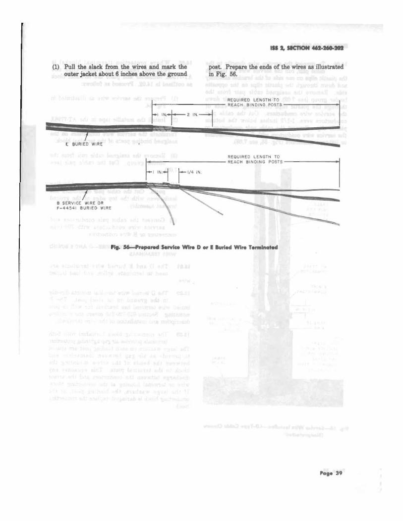
IERMINATINO 3IRVICE WIRE-D AND EBUTIED wlIE TERAAI}IAI
rEm,ll}{Afl XO glRVlGE W|IE--'3UPER!EDEDtY?C CAILE CIOSUR,EI
ilTMNAflilC IURED WITE.I2SAIA ANOtrt^ra-2 ?toftctoRs
BUR,IED WIRE
DESCRIPTION AND TERMINATION
CONTEI{T3 PACE
@ Anerican Telephone rnd Telegnph Conpeny, l9l{
PriDt4d iD U.S.A.
llcnoil &*nlur 1 Fobruory lff|'
,.
8.
+
,.
t.
3
3
r. oEl{ElAt
l.0l This eeetion covers the description andtermination of B service wire, F-59i10? and
F-593?? filled service wireg, F446,11 annor€d sewicewire, and E buried wire.
LOl. This section i8 reiseued to include:
e Information for terminating setrice wires inthe F cable closure in the euperseded cableclosure sectiong (Part 16)
o Information for terminoting service s'ires inthe PC6/48 ceble closures.
o Information for splicing filled seryice wiregand enclosing splice with 15AW1 senrice wiresplic€ closure, 13- and 14-type prefilledwaterproof dietribution closur€s.
Since this ia a general revision, arrows showingchanges have been omitted.
t.0:l The outer jacket of buried wire is markedat 2-foot intervals, from the inside end, to
show the accumulated footage. These markingseimplify the measuring and recording of wirelengths for accounting purToses and permit a moreaccuret€ meagurement of lengths being cut to fita specific location. The markings also indicate theamount of wire remaining on a reel.
l.0f E buried wire supersedes D undergroundwire.
1.05 The recommended depths for placing serviceor distribution wires are specified in Section
629-20G206.
2. 3 SERVICE WIREJESCRIPNON
2.Ol B senrice wire is intended for direct burialwithout added mechanical protection in
nonrodent infest€d areas. It is used as a burieddrop connection to cuatomer's premises. Its useis limited to lengtha not to exceed 500 feet. The
5.
6.
l l
t2
17
l8
il.
t2.
t5.
36
48lr.
Pogo I

ttcnofl ,/,'r-a{i'-.ro
sppmximste breaking atrength is 280 pounda. Itweighs 86 pounds per 10fl) feeL
Lt2 B seryice wire, ahown in Fig. t, consists ofone quad of 2Ggauge (AWG) copper covered
steel corductors, individually inrulated with distinctivelycolored (red, green, yel low, and black) sol idpolyethylene. The ingulation of the conduetors iscolored for pul'po$e of identification.
Rltr6 | TtP
PAIRS
Fl1. 14 3owlcr Wlrr
2.00 The quod is formed into a spiral and isjacketed witft gray PVC underlaid by a jacket
slitting cord of nylon. An aluminum tape is appliedover the jacketed quad snd is covered with anouter jacket of bleck PVC which is also underlaidwith a slitting cord of nylon.
2.U B gervice wire is furnished:
. On reels containing lengths total ingapproximately 5000 feeL
o On small reela containing lengths totalingapproximately 2000 feet for uge with thepivot mounted vibratory plows.
o In coils of apprtximstely 1000 feet for usewith C drop wire reels.
3. FIIED SIRV|CE WnES+EsC$mOil
&0t F-5930? filled gervice wire (Fig. 2) is thesame as B genrice wire except:
(a) A flame and. water regigtant thermoplasticcompound is applied throughout the quad
and enclosed by a vinyl jackel
tT
OUTERJACXET
FIIG TIP
PAIRSYELLOf _ ILACX
Flg. 2+-59007 Fllbd Sorvlcr Sflrr
(b) An inner jacket rip cord is not provided.
3.Ot fire F-598?7 filled sewice wire ig intendedfor use in providing buried genrice connections
and is approved for building entrances.
3.00 The F-598?? filled gervice wire (Fig. 8)consists of five pairs of. D.geruge solid copper
conductorg individuelly insulated witll distinctlycolored polyetlylere." The inrulrtion on theconductorg is colored for purpocc of identificrtoDi.
TYLil3L[trxc coto
26 rN.
INNERJACXET
PAIR NO. TIP RII ' IG
WHITE ELUE
WX ITE ORANG€
WH ITE GRE E I{
4 IV H ITE BROWN
5 WHITE SLATE
ALU$MITAIE
iYLdsLtTtrNG cmo
tt
ALUXtiUXTAPE
NYLONsLrlTr N6
I NN€RJACXET
Pogo 2
?tg. ilH./5lltf,l llllod Sorvlcr{lh

AOa A flame ond water resistant thermoplasticfilling compound ia applied throughout the
twieted pairs and encloaed by an inner vinyl jacketA helicel bronze tape ehield ig applied over theinner vinyl jacket A slitting cord of nylon ir laidbetween the bronze tape shield and black outerPVC jackeL
t Ot The F-69877 filled genrice wire is furnished:
r On reels containing lengths total ingapproximately 5000 feet. The lengths ofpieces ere msrked on tlre reel. No lengtlrof wire is less than 10ffi feel
o On small reels containing 950 feet for usewith wire plows.
+ F-aa54l AIIMORED SIRY|CE wnE+t3G$mOil
{.01 F-44641 armored gervice wire is a rodentresigtant-wire intended for direct burial
without added mechanical protection in rodentinfested areag. I t is used a8 e buried dropconnection to cuetome/s premises. Ite use is limitedto lengths not to exceed 600 feeL Ttre approximatebreaking atrength is 200 pounda. It weigha 39pounds per 1000 feet.
a.gll F-44641 armored eervice wire, shown inFig. 4, consists of one quad of 22-gauge
(AWG) annealed copper conductors, individuallyinsuleted with distinctively colored (red, green,yellow, and bleck) solid polyethylene. The insulationof the conductors ig colored for purpose ofidentification.
PAIFS
trl l, tlcllil m.*n
+6 The qued is formed into a spirel end irjacketed with gray PVC underlaid by jacket
slitting cord of nylon. A stsinless steel tape isapplied over t}e jacketed quad and is covered withan outer jacket of black PVC which is also underlaidwith a slitting cord of nylon.
a.0a F-44641 armored gervice wire is packagedin the same manner as B gervice wire (see
2.04).
5. I IURTED rv|iE4:SGRrmOr
5.01 E buried wire is a rodent regietant wireintended for direct burial without added
mechanical protection. It is uged for buried rureldigtribution of telephone cireuits. The epproxirnatebreaking strength ia 200 pounds. It weighe 61pounds per 1000 feet.
Nob: The 600 foot limitetion for B seFdcewire, filled rervice wire, and F448ll armoredgervice wire does not apply to E buded wire.
5.92 E buried wire, shown in Fig. 5, consists oftwo parallel l$gauge (AWG) annealed copper
conductors, insulat€d with bmwlcolorcd polyetlrylore.An armor of flat bronze tape is applied over theingulated conductors and is covered with an outerjacket of blaek PVC wNch is underlaid with a nylonslitting cord. One conductor ig tinted o bluishwhite color for conductor identification,
/Vob the browrreolorcd polyethylene condrctcinsulation is provided wit} glots to facilitateseparation of the insulat€d conductora whencut with e suitable cutting tool, ie, diagonalpliers, splicer's scirsors, etc.
tnGSLITIIIG ffiO
s?ArrLE333'EEL TAE oltE cot{DucroR ts niTED a ELUlsll uHrT€ cot a
FOR COIOUCTOR to€XlrFlcJllora.
ilg. tt+-aalal Annorrd lrrrbd Wlro Flg. 5-.t lgrlod W|rr
Pogo t


9. TERMINATII{G SERVICE WIRH CABTE CTOSURE
9.0t When joining service wires directly to cablepairs or to the leads from terminal blocks,
prepare the service wire as illustrated in Fig. 15.
OUTER JACKET
r33 2,3tCnO]{ $2-re?o2
9.m Install the metallic tape of the service wirein the AT-?796X connector as illustrat€d in
Fig. 10. Tighten the screw.
Note: T\e screw doeg not have to be removedfrom the connector to install the service $'ire.
METALLICSHIELO
NYLON SLITTING CORO(CUT OFF AT JACKET)
Flg. lfPrcporrd Srrvlcc Wlrc E Goblc Glorurr
TPA 49t784
,ro- ". l-PAI RS
RING TIP
RED GREENYELLOW BLACK
I NSULATEDC ONDUC TORS(INNER JACKET
R EMOV EO)
Pogc I I

tfcno]f 1t .rtD-rl,
9.09 Run the sCrvice wire through the plasticclips on the bracket assembly and down
tluough the plastic clips on the backplate (Fig. 16).
9.04 At each cable butt, place binder groupidentification ties (see ?.01) around the binder
group containing the cable pair to be connected.Remove the unit binder. Remove the assignedcable pair from the binder group and cut the cablepair (see 7.02). Place the cable pair up throughthe plastic clip on the backplate and bend down.Cut the cable pair and service wire conductorseven, l-L/Z inches below the plastic clip. Connectthe gervice wire conductors to the cable pairconductore with ?00-type connectorg or B wireconnectors (Fig. 17 gee ?.03).
9.05 Where the cloaure has terminal blocks, proceedas followg:
(a) Remove the outerjacket from the servicewire and install the metallic tape in the
AT-?796X connector as illustrated in Fig. 10.
O) Run the senrice wire up through the plasticclips on the bracket assembly and terminate
the conductorr on the assigned binding posts ofthe terminal block (Fig. 1?).
(c) Run the leads from the assigned bindingposts up through the plastic clips on the
bracket assembly and down through the plasticclips on the backplate (Fig. 1?).
(d) Remove the assigned cable pair from thebinder gmup, place binder group identification
ties as outlined in 9.04.
(e) Cut the cable pair (see 7.02). Place thecable pair up through the plastic clip on
the backplate and bend down. Cut the cablepair and terminal block conductors even, 1-1/2inchee below the plastic clip. Connect theterminal block conductorg to the cable pairconductors with ?00-type connectors or B wireconnectore (Fig. 1?, see 7.03), then attach servicewire conductor to appropriate terminals on theterminal block.
Pogr 12
r0. TEnMNATI{O SERVTC|E WtthJ CAtrE CIOSUiE
10.01 When joining service wire directly to thecable pair prepare the service wire and
ingtall the metallic tape in the AT-??96X connectoras illustrated in Fig. 10.
l0.0tl Run the service wire through the plasticclip on the bracket assembly and down
through the plastic clip on the backplate (Fig. 18).
10.00 At eaeh Cable butt, place binder groupidentification ties (see ?.01) around the
binder group containing the cable pairs to beconnected. Remove the unit binder. Remove theassigned cable pair from the binder group and cutthe cable pair (see ?.02). Place the cable pair upthrough the plastic clip on the backplate and benddown. Cut the cable pair conductors and servicewire conductors even, l-l/2 inches below the plasticclip. Connect the service wire conductors to thecable pair conductorc with ?00-type connectors orB wire connectors (tr'ig. 18, see 6.03).
10.04 Where the clogure has terminal blocks.proceed as follows:
(a) Remove the outer jacket from the servicewire gnd install the metallic tape in the
AT-??96X connector as illustrated in Fig. 10.
(b) Run the service wue up through the plasticclips on the bracket assembly and terminate
the conductors on the assigned binding posts ofthe terminal block (Fig. 19).
(c) Run the leads from the assigned bindingposts up through the plastic clips on the
bracket assembly and down through the plasticclip on the backplate (Fig. 19).
(d) Remove the assigned cable pair from thebinder group. Cut the cable pair (see 7.02).
(e) Place the cable pair up through the plasticclips on the backplate and bend down. Cut
the cable psir and terminal block conductorseven, l-\/2 inches below the plastic clip. Connectthe terminal block conductors to the cable pairconductors with ?00-type connectors or B wireconnectorg (Fig. 19, see 7.08). Attach the servicewire to appropriate terminals on the terminalblock.


ttcnolf $2-ire'o,
ll.0a At locations where fuge wire or cableproteetion ir required, terminal blocks (Pa,rt
6) are installed in the KB5- or KOb-type cableclosures (F-rg. 28).
11.05 To inetall the seffice wire in the KBL orKCFtype cable closures, prnceed as follows:
(a) Mark and remove the outer jacket from thesendce wire as illuetrated in Fig. 20 and 21,
respectively. Inetsll the metallic tape of thegervice wire in the AT-?796X connector asillustrated in Fig. 10.
(b) Run the gervice wire conduetorr up themounting bracket aBsembly and terminate
the conductors on the assigned binding post ofthe terminal block (Fig. 28).
(c) Run the leads from the assigned bindingpost down through the wire bracket of the
KB5-type cloeure or into the splicing area ofthe KCFtype cloeure (Fig. 28).
(d) Remove the assigned csble pair from thebinder group. Cut the cable pair (see ?.02).
(e) Place the cable pair through the wire bracket(KB6-type elosure) or into the splice area
(K0ttype closure). Cut the cable pair conductorsand terminal block conductors even. Connectthe terminel block conductors to the cable pairconduetors with ?0O-type connectors or B wireconnectors (Fig. 23, see 7.08). Attach servicewirea to appropriate terminal on terminal blocks.
11.06 Where the service wires 8re to be joineddirectly to the cable pair in the KCStype
eable closure, prepane the seryice wire and installthe metallic tape in the AT.??96X connector asoutlined in 11.01 and 11.02. Proceed as follows:
(a) Place the gerwice wire conductorg and cablepair conductors down through the wire
brecket. Cut the service nrire conductors andc&ble pair conductorg even, L-l/2 inches belowthe wire bracket. Connect the service wireconduetors to the cable pair conductors with70Gt!"e eonnecton or B wire connectors (Frg. %,see 7.08).
12. Tttl,llilArtilO SttYtCt W[tt-ttt WttcroSutc+NCAPSUlAnOX
t2.01 The Pee Wee Closure is used to join newburied genrice wireg or to repair damaged
Bervice wires.
12.t2 fire following precautions must b€ obsenedwhen using the Pee Wee Closule:
(a) Do not op€n or remove the outer bag which
- contsins tle plugging compound until ready
for use.
(b) Avoid prolonged or repest€d contact withskin or brcathing of vopors.
(c) Use only with adequate ventilation.
(d) In case of contact with the eyes, flush withwater for at least 16 minutes and get medical
sttention.
(e) In cold weather, before mixing, preheat theplugging compound to approximately ?OF.
l2.Olt The Pee Wee Clogure (Fig. 2E) is anencepsulated splice kit which contsins the
following components:
(a) Plugging compound (polyurethane)
(b) Split bolt clanp
(c) Two end cape
(d) lVo pieces of tubing<ne split and one withan elongated slol
Note: The B wire connectors used to jointhe conductorr must be ordered aepantely.
PcAc 18


C. O. SI D E
SERVICE WI R ES CONNECTEDTO CABLE PAI R S WITH700 T YPE CONNECTORS
C.O. SIDE
FIELD SI DE
SERVICE WI R E PAIRTO BE SPLI CED TOCABLE PAIR
P . 40—SplIcles Cable PoIrs-13-Type Cosine
TIE SPLICED CONDUCTORSTO CABLE CORE WITHINSULATED WIRE
CUT CABLE PAIRS TO BE SPLICED ONSIDE OF OPENING AWAY FROM C.O. LEAVEAT LEAST 2 INCHES ON FIELD SIDE
g. 41—Vilre We& Complete-14-Typ* Closure
MS 2, IIICTION 41111411241112
CUT CABLE PAIRS ON SIDE OFOPENING AWAY FROM C.O. L EAVEAT L EAST TWO INCHES ON FI ELDSIDE.
2 I N .
WRAP AT - 7 7 9 6 xCONNECTOR WI THVI N YL TAPE
SPLICES MADEWITH 7 0 0 -TYPECONNECTORS
FIELD SI DE
29


,I/t
a
I
rcrFr u.bm
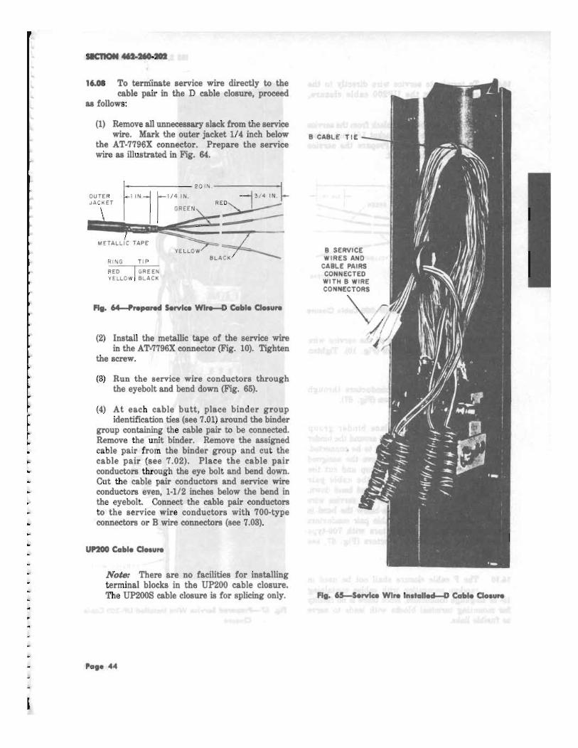
(3) Run the ceble pair up through the plasticclips on the wire bracket and bend down
Grg. ?1).
(4) Cut the service wire conductors and cablepair conductors even, 8 inches below the
top plastic clip.
(6) Connect the cable pair and service wireconductors vith B wir€ connector€ (gee ?.03).
(6) Insert the B wire connectors as far agpossible into the filled F plastic eap.
(7) Fold tlre F plastic cap at a point approximately1/4 to 8/&inch fmm the nearegt connector,
The gilicon rubber compound should extrude toboth gides of the fold. Place the folded eap sothe open end faceg downward. Ttis will preventthe collection of the water in the cap, Bindthe folded cap with a scrap conductor or tapewith two turns of vinyl tepe (Fig. 71).
17. tElMrl{Afl}ro tuRtED wrRE-t23ArA AilDt28ArA-2 PrOftCtOtS
t7.01 Before instsiling protectorr, tbe followingshould be token into consideration:
(tl fttula hotetaE fire length of groundwire from the prrtector should be as short
as poseible to provide a low-reeistance path togtound.
(b) Accecelblllty: The protectors ghould beplaced where they can be reached from
ground level.
(cl Appatznoer Avoid locationg on the frontsof buildinge or in living quarters.
(d) Iasdn otTalephone And Powv Gmud:The telephone ground shall be locsted to
facilitate common grounding.
lVod* Section 4@10G201 coverg the selectionsnd installetion of gtation protector groundand signaling grounds.
(e) Dry and well ventilated locationg wheninstalled indoors or underaeath buildings.
(0 Where poasible and with permission of tfiepower company, eDtrance into tlte custome/a
premises through the same opening as the powercompsny wirea provided:
(f) The power service cable and telephonegervice wire that serve the building are
in random conetruction.
(2) fte entrance hole or sleeve through thefoundation is lese than 2 feet long.
(8) There is adequate cross sectional area inthe hole or sleeve to place tlre power eable
and telephone service wire without damageto eit}er.
ll.gi, Protectort installed indoors may be mountedin any position,
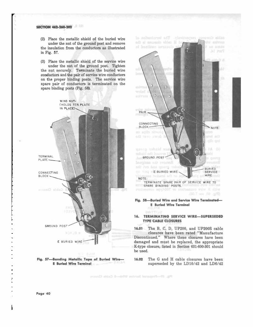
17.0t Terminate the buried wire and inside wireon the protector so the ring conductors
(single trecer or red and yellow wires) shall beconnected to the binding posts on the right sideof the protectorg. (On ceilings, the right side asviewed from the inside wiring end of the protector,)
l7.U All scr€ws 8nd fasteners sholl be ofeufficientlength to mount securely, The 080 Division
of the Bell System Practices contains informationconceraing the varioug types of screws, anchon,etc, required to inatsll the protectors.
Pogr 48
17.05 T h e size ground wire required for singleor multiple installation of protectors is listed
in Table A.
GROUND NO. OFWIRE PROTECTED CIRCUITSSIZE FUSELESS
No. 14 1No. 12 2No. 10 6No. 6 7 or more
TABLE A
GROUND WIRE CAPACITY
Note: The ground wire between protectorsshall be the same size as the ground wirebetween the protector and the groundingelectrode.
Na m The ground wire between protectorsshall be the same size as the ground wirebetween the protector and the groundingelectrode.
I tWhen the Jidda! protector groand why
iff Manlike& i t should be of sailledentsize to provide protection for anyibtorepsytectorinstidknion Ma k , AL
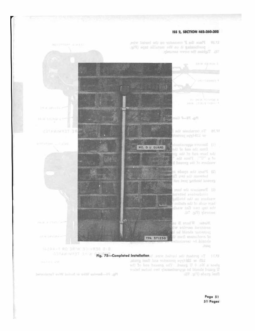
WM Unless otherwise indicated, the 128A1A or128A1A-2 protectors should be installed, on
the wall, directly above the location where theburied wire enters the ground.
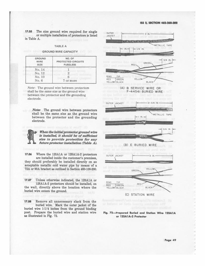
17.05 Remove all unnecessary slack from theburied wire. Mark the outer jacket of the
buried wire 1-1/4 inches from the ground bindingpost. Prepare the buried wire and station wireas illustrated in Fig. 72.
OUTERJACKET
1 1 1 1 1 . 1 1 1 1 1 . 1 1 1 . . . 11 1 1 1 1 1 1 1 1 1 1 1 1 P METALLIC TAP E
1._,/4 IN.
RING T I PREDYELLOW BLACK
OUTER JACKE T
RING T I PRED GREENYELLOW BLACK
RED
155 SOCTION 40115110410
3 IN .
GREEN
YELLOW
to-I IN.-1
BLACK
(A) B SERVICE WIRE ORF-4454I BURIED WIRE
ta----2 3/4
-1 3/4 IN.
(B) E BURIED WIRE
METALLIC TA P E
- 1 3 /4 IN . r_11111111111•11111
17.06 Whe re the 123A1A or 128A1A-2 protectors O U T E R JACKET • 3 IN
are installed inside the customer's premises, 1 . . .i. . = m . . . . . . . . . . . . . m m u sr I
they should preferably be installed directly on anacceptable metallic cold water pipe by means of a72A or 90A bracket as outlined in Section 400400-200.
BLACK
(C) STATION WIRE
Pis. 72—Irrepered lul led and Stades Wire 1211A1Aor 123A1A4 Protector
Page 49