burj al arb
DESCRIPTION
one of the beautiful highrise buildings in the worldTRANSCRIPT

Article
3 r d Q u a r t e r 2 0 0 6
I
Burj Al-Arab, UAEStructural Steel Construction ForA Mega ProjectBy Dato’A K Nathan, Managing Director, Shin Eversendai Sdn Bhd
n recent years, all over the world, the construc tion industr y is emerging ver y rapidly both in
engineering and technology, and contributing significantly to economic development. In the later part of the past century, there has been extensive usage of steel in the construc tion industry and steel explored much more possibilities to substitute other conventional materials.
With today’s structural steel framing, grace, ar t and function can come together in almost limitless ways; it offers new solutions and opportunities, allowing architects to stretch their imagination and actually create some of the most challenging structures they have designed in their minds.
Structural steel has entered a new era. Today it provides not only strength to buildings but also beauty. Steel is not only being used to provide a stable framework for a structure but in many cases is also chosen for its aesthetic appearance.
Eversendai have had the good fortune to be invo lved in steel structur e projects of diverse types one of which was The Burj Al Arab. It will demonstrate the versatilit y of steel for various applications and also illustrate the various complexities:-
Designed to resemble a billowing sail, one of the most fascinating, majestic, wonder structures in the world, the Burj Al Arab soars to a height of 321m,
Burj Al Arab
dominating the Dubai coastline. This all-suite hotel reflects the finest that the world has to offer. An architectural marvel, it is an engineering excellence for the 15 th tallest building in the world.
It is the world’s tallest hotel structure. This project has become Eversendai’s signature project and it has paved the way for Eversendai’s entry into the Middle East’s booming construction
market as a specialist structural steel

Article
3 r d Q u a r t e r 2 0 0 6
contrac t o r. No w Ev ersendai is dominating their presence in the Middle East.
The Burj Al Arab means “Tower of the Arabs” is situated at Dubai,
United Ar ab Emirat e s, designed by Mr Thomas Wills Wright. It stands in the sea, 280m away from the beach in the Persian Gulf on a man made island connec ted to the main land by a private curving bridge. It has access by Land, Sea and Air.
77

It is one of the most fascinating, complex and challenging project ever undertaken by Eversendai.
The structure is a standing example for the quote “Architect’s Dream, Engineer’s Night Mare”.
Steel is the best-opted material for this building due to its flexibility and constructability.
The Burj Al Arab building is made of 28 storeys of split levels (56 storey) with100,000 m2 floor area, 60000 m3 of concrete, 9,000 ton of reinforcing steel,12,000 ton of structural steelworks,80000 m2 of cladding,10000 m2 of teflon- coated fiber glass cloth and sits on 250 piles of 1.5m in size, 45m under the sea, the piles rely on friction as there is only piles embedded in sand to hold the building up.
Construction of the Burj Al Arab hotel began in1994, and its doors were opened to guests in December,1999. The top is the mast and below it is the helipad, and extending from the other side of the hotel, over the ocean, is a restaurant supported by a cantilever structure. A remarkable element of its architecture is the outer beachward steel wall of the atrium, which is covered
Hybrid V shape structure
with a woven, Teflon-coated fiber glass cloth. The Burj al-Arab features the tallest atrium lobby in the world standing at 180m.
This Burj Al Arab building is a hybrid V shape structure constructed in concrete up to 209 m and blended with structural steel creating an impressive engineering master piece. This V- shaped frame wraps around the V reinforced concrete tower containing the hotel rooms and lobbies. The two structures connect along a shored, reinforced concrete spine at the base of the V, and at two points along the curving atrium wall.
Ninety percent of the steel structures constructed were outside the building and was potentially dangerous to erect. Three self-climbing tower cranes with a maximum lift capacity of 64 tons at 8.0 meters radius were used. Some of the embedment weighed as high as 60 tons.
About 100 tons of electrodes were burned and the welding defect ratio was less then 1%.
The Burj Al Arab does not have ordinary rooms; rather it is divided into 202 duplex suites with split levels. The

smallest suite occupies an area of 169 sq m, and the largest one covers 780 sq m. It is one of the most expensive hotels in the world to stay in. The cost of staying in a suite begins at US$1,000 per night and increases to over US$15,000 per night; the Royal Suite is the most expensive, at US$28,000 per night.
We are proud to say that this project was the major break through for Eversendai Engineering in Middle East region. The Project was been awarded to Eversendai purely based on its construction methodology, capability and reliabilit y. Eversendai scope includes the site assembly, alignment, welding and erection of structural steel works.
Total Steel works are phased into Exosk eleton R ear leg, Horizontals, Diagonals, Rear Brace Frame, Helipad, Sky Restaurant, Atrium and the Mast :-
Exoskeleton Rear leg Erection
The exoskeleton is made up of two legs on both sides of the building starting from the ground level to 273 meters and connected to the front legs starting from 208m. The total weight of the struc ture is about 2,800 tons. The structure was made of two build up H sections of 1.8 metre wide by 4.5 metre deep plate girders (inner and outer legs)
connected by a lattice braced members and segmented to 40 ton capacity 12m in length to create the gentle curve in concurrence with the building edge developing the shape of a sail.
The assembled segment were lifted and erected in position using the tower cranes from ground floor to top, one over another using specially designed lifting lugs with 20 ton chain hoists in the pre-determined lifting location to lift the segment in required angle.
Af ter each segment were erec ted, temporary struts were introduced to tie back the rear leg to the core wall to
78

Framework
maintain alignment until the Exoskeleton grows to the next point of permanent connec tion and then connected permanently with the Link Stud weighing about 10 tons to the concrete core. There were three Link studs on each side of the building, fixing at three points for the entire length of 273 metre Exoskeleton to the diagonal brace and horizontal brace point and continued erection of the segment only after the erection of diagonals and horizontals and finally connecting to the front legs starting from 208m.
All exoskeleton are lif ted in predetermined angles adjusted by chain blocks, hooked on to the crane and lifted in segments. All the joints are of full penetration welding and inspected by ultrasonic test.
Platforms were fitted at each joint for welding and other related works
Alignment was carried out using electronic digital total station located at three different fixed locations, all surveying are done very early in the morning to get a more accurate reading, keeping in mind the movement of the structure due to thermal effects which generally develops deflection.
Rear Brace Frame
The two cores on the rear side of the building are 40m apart and connected by huge cross bracings of fabricated box sections called the rear braces.
The box sections were brought into the site in transportable segments. The cross sections of the boxes are 2.2m by1.4m and made of from 25mm to 40 mm thick plates. The box sections are assembled and welded at the ground level by the side the building.
This brace ties both the cores together to give stability to the structure. The total tonnage of this part alone is 1600 tons. The shape of the Rear Brace is similar to “X “are erected in segments. All the joints are of full penetration welding.
These rear braces form as X of three portions for the whole building. The length of one brace was around 60m in one direction from one side of the bottom embedment to the upper embedment of the other side of the core, it was spliced into three pieces. The first piece was about 24m and weighs about 50 tons and was lifted by two tower cranes as a tandem lift and erected between core embedment from one side and the another end rested on the temporary lattice girder trusses running between cores to suppor t the rear brace segmental erection. Once these two 24mts braces were erected then the X of 12m length of 52 tons was erected by two tower cranes as tandem lift supported by the second layer of temporar y lattice girder truss, which was erec te d between cores, the whole rear brace is in inclined towards the inside of the building. After all welding, touch up inspections been carried out, all the temporary platforms, scaffolds and the three lattice girder trusses were removed from its position and re – erected to the upper portion of the rear braces location to continue the
same process of erection to complete the three portions of X rear braces in the building.
Diagonals
The diagonals are of huge tubular triangular truss geometry having the maximum cross section at the middle length and merged as one member at the ends. The Diagonal vary from 76m to 90m in length and weigh 160 to 180 ton. The Diagonal connec ts with a300mm diameter pin connection to the co re -wall and the Rear-leg struc ture. There are six diagonals erected at different levels on both side of the building.
These diagonals are transported as a single fabric ated piece from the fabrication shop 15 km away by special self propelled long trailers.
Strand jacks supported by Cat heads were connected to the building to execute the lifting of the Diagonals and Horizontals. U tmost care was taken to ensure that the measurement length bet ween the core and theexosk eleton rear leg so that the diagonals with pin connection can be connected with ease.
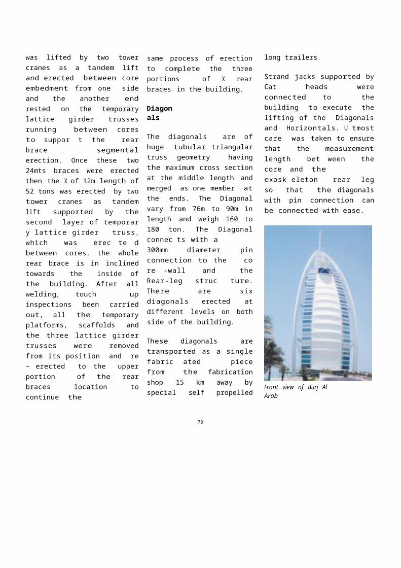
Front view of Burj Al Arab
79

Horizontals
The horizontal weighting about 200 tons connects the core wall to the exoskeleton rear leg. This structure was assembled in one piece in the assembly yard near the project side. The Horizontals were transported by long special self-propelled trailers to the erection site.
They had to be erected between two fixed points so utmost care was taken to measure the length between the core and the exoskeleton rear leg.
Horizontal were erected by strand jacking method similar to Diagonals, using the same cat heads platforms.
Once the horizontal reached its determined elevation, then it was slide towards the building and placed to its position connected with bolts and welding.
The strand jacks and the cat head platforms were removed from its position and kept ready for the next cycle of operation. Once cat heads and strands were removed then the Exoskeleton typical erection sequence was carried out up to its level to the next diagonal and horizontal fixing point and then stopped to continue diagonal and horizontal strand jacking operation.
Helipad Structure
This structure is at 212m level at the rear side of the building, weights about 330 tons made up of steel trusses and 20mm thick plates. Two props of 1m diameter circular steel pipes, forming an invertedV shape,tapered at 30º to the vertical andtied back to the center core by a 40m long spine truss weighing 120 tons, support the total Helipad structure.
Sky Restaurant Structure
The 350 ton structural steel skyRestaurant was one of the most complex
and potentially dangerous structures to erect. The box girders cantilever out for about 30m from the main core wall of the building connected to about 200 tons of embedment. The restaurant is having a floor size of 70m x 25m. The total structure is built up on eight cantilevered box sections and two end trusses at 200m above the ground level. The beauty of the restaurant is that it over looks the sea. One of the highlights is, two 30m long girders had to be erec ted at 200m level but the crane did not have the lifting capacity so we had to split the girders into halves and joint up in the air with full penetration welding, it was a real challenge and Eversendai took it up and per formed beyond ever yone’s expectation in a record duration of 40 days.
Mast
The mast is about 104mts long, only54m was braced in bet weenExoskeleton support legs starting from208m level on the core wall and the balance cantilevers vertically 50m way above the Exoskeleton.
The overall mast was erec ted in segments of average 30 ton weight matching the tower crane capacity. The

mast is in oval shape of 2.5m x 5m at the bottom and gradually decreases to 2.5 x 2m at top. All the segments were bolted inside by r ing plate flange connections. All the segments had inside arrangements of permanent ladders and inter val platforms to facilitate access and maintenance.
The first segment of the mast was erected af ter the Exoskeleton was erec ted on the trusses which run between t wo Exosk eleton legs in horizontal plane.
There were manholes at per iodic intervals, through that workers had access to go and come out from the mast to the nearby Exoskeleton temporary scaffolding arrangement. Temporary Safety exhaust fans were introduced inside the mast to have air circulation to
workers.
Before the mast erections coming to end with the use of the tower crane, the other two cranes were dismantled except the crane near to mast.
Finally the third crane was dismantled by derrick crane. After complete dismantling of tower crane,derrick crane was dismantled manually and lowered from the roof top by winches.
80