burner fuel use vs. tank temperature - ptac · · 2017-06-21enclosed flare flare . heavy oil ......
TRANSCRIPT

Heavy Oil Casing Gas Utilization Option Sheets – April 30, 2015
1 Prepared by New Paradigm Engineering Ltd.
Option Sheet 8.1: Increase Use of Surplus Casing Gas During years in which a well has a surplus of casing gas produced, the tank temperature could potentially be increased (within the limits of the fire tube rating and operator/trucker safety considerations) to burn off as much casing gas as possible to reduce GHG emissions. The added temperature may benefit operations at the central production battery and is a very low cost method of reducing some casing gas emissions. This requires only an adjustment to the set point of the tank temperature control, ideally under conditions of continuous firing, or the manual control if there is no temperature switch.
The above chart shows the difference in casing gas consumption for burner fuel use over the tank temperature range of 60-90°C (140-194°F). Chart is based on an assumed well profile where 800 m3/d (28252 ft3) casing gas is available. (Assumed well: 10 m3/d (353 ft3) oil, 18 m3/d (636 ft3) water, GOR 80 m3/m3, T1 = 20°C (68°F), 35% overall energy efficiency).
300
350
400
450
500
550
600
650
700
750
50 60 70 80 90 100
Bu
rner
Fu
el
Use (
m3/d
)
Tank Temperature (°C)
Burner Fuel Use vs. Tank Temperature

Heavy Oil Casing Gas Utilization Option Sheets – April 30, 2015
2 Prepared by New Paradigm Engineering Ltd.
Option Sheet 8.2: Flare Stacks Flaring is deemed preferable to venting for all reasonable volumes of combustible waste gas. In Alberta, when vented gas volumes are significant on a site (greater than 500 m3/d or 17657 ft3/d) operators should consider opportunities to eliminate or reduce vented volumes (AER Guide 60 Updates and Clarifications). The SEM currently has a 850 m3/d (30017 ft3/d) venting limit for heavy oil producing areas of Saskatchewan. Open flares are still a valid technology for flaring casing gas, as it is primarily methane without the heavier end liquids that typically cause most of the combustion efficiency problems with flares. There is no evidence that conversion in open flares with methane is an issue.
Costs vs. Capacity: Capacity: 100 m3/d – 1 MMSCF/d+ Flares: $6,500 - $195,000 Utilities: Pilot fuel of 0.76m3 (27 SCF/h) required 120 VAC for ignition system (if available) Operations and Maintenance: Burners can be designed for 1” w.c. 4:1 – 5:1 turndown (more with automatic controls) Key Factors for Success/Limitations:
Water/liquids knocked out upstream of flare.
Flare Stacks
Photo Courtesy Total Combustion Inc.
Enclosed Flare Flare

Heavy Oil Casing Gas Utilization Option Sheets – April 30, 2015
3 Prepared by New Paradigm Engineering Ltd.
Fuel lines freeze protected for winter operations.
Flame arrestors recommended. Environmental Impacts: Every tonne of casing gas that is burned instead of vented reduces greenhouse gas emissions by 18 tonnes of CO2 equivalent. Implementation/Regulatory Considerations: Flare stacks must be spaced a distance of at least 25 m (82 ft) outside the boundaries of a hazardous location (of any Class), at least 50 m (164 ft) from any well head or oil storage tank, and at least 100 m (328 ft) from any occupied residence or off-site surface improvements. Stack height is set based on H2S levels if applicable. For Alberta, AER Guide 60, Upstream Petroleum Flaring Requirements, became effective 1 Jan 2000. Guide 60 sets forth solution gas flare reduction schedules, use of a flaring management decision tree to assess new flares, and personal consultation and public notification requirements. CAPP has also produced CAPP Publication #1999-0014, Recommended Practices for Flaring of Associated and Solution Gas at Oil Production Facilities. Best Sites for Application: Sites where on site fuel has been backed out, other options such as gas gathering, power generation, and EOR have been utilized or ruled out, and there is still significant excess casing gas being vented. Examples of Suppliers: Tornado Technologies Inc. Tel: 800-661-4128 Website: www.tornadotechnologies.com

Heavy Oil Casing Gas Utilization Option Sheets – April 30, 2015
4 Prepared by New Paradigm Engineering Ltd.
Option Sheet 8.3: Enclosed Flares If the visible flame from open flares is an issue (e.g. public perception) then producers could consider utilizing enclosed flares. Enclosed flares are essentially used to hide the flame – they do also improve combustion efficiency and can eliminate odors and smoke. They generally have simpler controls, shorter residence times, do not have refractory linings, and are used for higher flow rates than incinerators. They are more expensive than open flares, but are cheaper than incinerators. In the event that toxic or hazardous vapors are an issue and/or high levels of destruction efficiency are required, then incinerators would be used. Incinerators are generally fully automated to maintain temperatures and retention time and have refractory linings. They are generally custom designed for specific locations, conditions, and flow rates. They are also the most expensive technology. It should be noted that the terms enclosed flare and incinerators may be used differently from supplier to supplier.
Photo Courtesy of Total Combustion Inc. A Hy-Bon enclosed VCU unit is an example of an enclosed flare. It is used to destroy VOC's from a storage tank facility when vapor recovery is not economically feasible or as a Vapor Recovery Unit backup.
Enclosed Flares

Heavy Oil Casing Gas Utilization Option Sheets – April 30, 2015
5 Prepared by New Paradigm Engineering Ltd.
Hy-Bon Vapor Combustor
Costs vs. Capacity: Capacity: 100 m3/d – 1 MMSCF/d+ Incinerators/Enclosed Flares: $19,500 - $650,000 Specifically for a Hy-Bon Vapor Combustor, the combined VRU, VRT, VCU and installation: $130,000 with a payout of 9 months Utilities: Pilot fuel of 0.76 m3 (27 SCF/h) required 120 VAC for ignition system (if available) Installation: Size of units – an example 0.28-1.42 m3/d (10-50 MSCF/d) incinerator systems is 4.88 m (16 ft) height, 0.51 m (20’’) wide, and weighs 1134 kg (2500 lbs). The required stack height is set by H2S levels if applicable. Operations and Maintenance: Burners can be designed for 1” w.c. 4:1 – 5:1 turndown (more with automatic controls) Key Factors for Success/Limitations:
Water/liquids knocked out upstream of flare.
Fuel lines freeze protected for winter operations.
Flame arrestors recommended. Energy Efficiency or Other Benefits: Incinerators and Enclosed Flare designs have no visible flame, no smoke, and no odors. They can achieve 99.9% combustion efficiency, but are more expensive than

Heavy Oil Casing Gas Utilization Option Sheets – April 30, 2015
6 Prepared by New Paradigm Engineering Ltd.
conventional open flares. Environmental Impacts: Every tonne of casing gas that is burned instead of vented reduces greenhouse gas emissions by 18 tonnes of CO2 equivalent. The Hy-Bon Vapor Combustor results in the removal and complete combustion of vented tank vapor. Implementation/Regulatory Considerations: EPA 40 CFR Quad O Compliant Best Sites for Application: When vapor recovery from storage tanks is not economically viable or as a Vapor Recovery Unit backup. Examples of Suppliers: Tornado Technologies Inc. Tel: 800-661-4128 Website: www.tornadotechnologies.com Total Combustion Inc. Red Deer Tel: 403-309-7731 Questor Technology Inc. Calgary Tel: 403-571-1530 Website: www.questortech.com Hy-Bon Engineering Company Inc. Midland, TX Tel: 432-697-2292

Heavy Oil Casing Gas Utilization Option Sheets – April 30, 2015
7 Prepared by New Paradigm Engineering Ltd.
Option Sheet 8.4: Catalytic Converters Catalytic conversion of methane to CO2 has potential to be an economic method of converting low volumes of methane on a well lease. The units can be located in Class 1, Div 1 or Div 2 areas. They are small, compact and easy to operate as they are essentially catalytic building heaters. A major advantage in this application is that they can be modular so that the capacity installed will match the capacity required. Existing commercial heater units are available, which can provide this function but are expensive as they are designed for use as building or enclosure heaters. Designs can be simplified to focus on conversion alone. Unit shown below was used in a trial in the Morgan field.
Costs vs. Capacity:
Catalytic Line Heater (120,000 BTU/hr or 80 m3/d of methane) - $18,700/unit. Assuming a 10 year life this would be $2.20/t CO2 eq reduction as there is little or no incremental operating costs vs. current GHG emissions trading range of $2-$2.6/tonne.
Catalytic Converter – Current target is to reduce capital costs to below $1.3/tCO2eq over a 10-year life. Cost will likely be proportional to capacity of unit.
Utilities: 12 volt truck battery for initial start-up. Installation: Size of units – Current catalytic heater units are a function of heater area, but can range from a few square inches to many square feet as either single units or unlimited capacity with multiple units. A 120,000 BTU/hr catalytic line heater has 1.86m2 (20 ft2) of total area in four panels. Conversion of methane is 4m3/d/ft2. Operations and Maintenance:
Heaters require gas at 3.5” W.C. (<1/2 psig)
Turndown per panel is 30%, total unit turndown ratio is dependent on the number of panels installed.
Key Factors for Success/Limitations:
Freeze protect vent gas to the heater.
Modular design to match the amount of vent gas available requires modules be
Heavy Oil Casing Gas Utilization Option Sheets – April 30, 2015
8 Prepared by New Paradigm Engineering Ltd.
managed to optimize benefit.
Benefits can be increased by finding any use for the waste-heat generated from the conversion reaction. E.g. generate power, warm equipment, heat production.
To realize GHG emissions credits, operation or vent volumes must be verifiable. Environmental Impacts:
Converting casing gas reduces greenhouse gas (GHG) emissions by a factor of 7 vs. venting (CO2 equivalent basis). Each tonne of casing gas that is burned reduces emissions by 18 tonnes CO2 equivalent.
Catalytic heaters convert methane at a low temperature so there is little or not formation of NO or NOx.
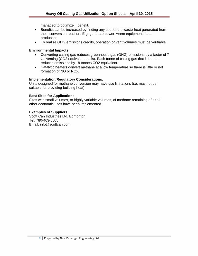
Implementation/Regulatory Considerations: Units designed for methane conversion may have use limitations (i.e. may not be suitable for providing building heat). Best Sites for Application: Sites with small volumes, or highly variable volumes, of methane remaining after all other economic uses have been implemented. Examples of Suppliers: Scott Can Industries Ltd. Edmonton Tel: 780-463-5505 Email: [email protected]

Heavy Oil Casing Gas Utilization Option Sheets – April 30, 2015
9 Prepared by New Paradigm Engineering Ltd.
Option 9.1: Vapor Recovery One option is to provide better containment of the odors and to reduce the fugitive emissions on the well site by recovering the vent gas stream from the tank. Reducing the fugitive emissions reduces the odor concentration from the site at the source. A vapor recovery system would require a make up gas stream to maintain blanketing on the tank, a dual pressure controller, and emergency pressure protection for both vacuum and overpressure relief, a compressor sized for the normal gas load, and some type of gas scrubbing/absorption to clean up the gas prior to use or sale. The requirements for gas purity and cleaning will be different if the gas is used on site than if the gas is to be offered for sale. This analysis will need to be done on a well-by-well basis. Some of the factors to be considered are the vent gas flow rates, the consistency of the flow rates, the ability to use the gas either on site or to get the gas to market. The possibility of replacing emergency tank relief with a relief valve that is certified for fugitive emissions was explored. This type of relief is a one-time use, similar to a rupture disk. However, it has been certified to allow “No detectable emissions” prior to use. The vents are mounted in the vapor space of the tank and a pin holds the disk in place prior to emergency use. The force required to buckle the pin and open the relief valve is calculated for the pressure of the tank and the metallurgy required for the pin. These valves are certified to comply with VOC emission guidelines in the US. The tanks would still require some type of vacuum protection, and the possibility of emissions escaping from the vacuum breaker would probably nullify the effects of a bubble tight rupture disk. The cost for the vapor recovery system would be higher than most others, but it may offer a significant return in gas savings or sales. The estimate for this type of system is between $13k and $20K (Unclassified estimate + 50%).
Advantage:
Vapor Recovery
Blanket Gas Supply
To Recovery
Pressure/Vacuum Thief Hatch & Level Cable Seal

Heavy Oil Casing Gas Utilization Option Sheets – April 30, 2015
10 Prepared by New Paradigm Engineering Ltd.
Reduce or eliminate tank odors from venting.
Used in conjunction with an absorption method that could eliminate tank odors. Disadvantage:
Normal tank venting due to filling, emptying, foaming or temperature changes could still cause gas to be released to atmosphere if the pressure control system was not functioning.
Cost of installation is comparatively high.
Examples of Potential Suppliers: Tornado Technologies Inc. Tel: 1-800-661-4128

Heavy Oil Casing Gas Utilization Option Sheets – April 30, 2015
11 Prepared by New Paradigm Engineering Ltd.
Option 9.2: Tank Vent Condenser A simple air-cooled finned tube or extended area heat exchanger could be installed to condense hydrocarbon vapors from the tank vent stream. Cooling would be provided by natural circulation, so no coolant would be required and maintenance would be minimal. Freeze protection may be an issue in the winter with some types of exchangers. Ideally an extended surface condenser, such as those found on “Tank Safe BTEX Condenser Units” like that shown below would likely work best as the large flow area would prevent freeze-offs. The hydrocarbons would drain back into the tank or a separate sump depending on the exchanger height and location. Some skid-mounted exchangers are available, with one type showing C-6 hydrocarbon reductions in a vent gas of about 95+% efficiency. Other styles of condensers in metal and plastic are available, most use ambient air as a coolant.
Advantages:
Readily available coolant, ambient air
No other process steps or equipment, low pressure drop
No absorbents, solvents or sponge oil to dispose of.
Reduce the emissions of VOC, and reduce odor emission Disadvantages:
Possible water condensation causing freezing in the tubes and obstructing the vent line
Vent Gas Condenser
Air Cooled Heat Exchanger (adjustable)
Vent Gas
Liquids to Tank
Separator Pressure/Vacuum Thief Hatch & Level Cable Seal

Heavy Oil Casing Gas Utilization Option Sheets – April 30, 2015
12 Prepared by New Paradigm Engineering Ltd.
Heavy Oil Casing Gas Utilization Option Sheet
Option Sheet 9.3: Incinerate in Fire Tube As the vent gas volumes appear to be very low in volume (<10 m3/d or <353m3/d) it should be possible to modify the existing tank fire tube heater design to draw the tank vapors in with the combustion air when the tank burner is in operation. Flows could be limited to ensure that the heat output would not exceed the fire tube capacity. Energy for drawing gas in would come from the fuel/air eductor, which is already used to draw air into the burner through a flame arrestor. The tank vapors would then be incinerated in the fire tube.
Costs:
Assume $1,300 for vent gas line (installed during tank fabrication); small flame arrestor for vent gas line and vendor modifications to burner design to allow vent gas use.
Utilities: Insulate vent line and flame arrestor to bare tank wall to keep them warm and prevent condensation of water vapor. Installation: Best installed during tank fabrication with modifications to burner designed by burner vendor. Operations and Maintenance: Should require little operator involvement.
Fire tube
Tank Vapors
Tank Vent
Tank Burner
Heavy Oil Storage Tank
Vent Upstream Of Air Eductor
Flame Arrestor
Fuel Gas Vent Gas Line
(Insulate to Tank)
Air
Tank Vent Gas
Tank Vent - Incinerate in Firetube
Firetube

Heavy Oil Casing Gas Utilization Option Sheets – April 30, 2015
13 Prepared by New Paradigm Engineering Ltd.
Key Factors for Success/Limitations:
Freeze protect tank vent gas line.
Vent stream must be small in volume, contain only small amounts of heavy hydrocarbon and designed to prevent liquids entering vent line.
Burner vendors must approve design. Environmental Impacts: Any heavy components in the vent steam will be converted as will the vented methane. Implementation/Regulatory Considerations: Systems should be subjected to a hazard analysis study to ensure risks are acceptable compared to other options. Best Sites for Application: Sites with very small volumes or highly variable volumes of methane tank vents, which are causing odor problems in the area. Examples of Suppliers: Not available at this time.

Heavy Oil Casing Gas Utilization Option Sheets – April 30, 2015
14 Prepared by New Paradigm Engineering Ltd.
Option Sheet 9.4: Catalytic Conversion Direct catalytic conversion of tank vent streams can be difficult, as the tank breathing will tend to dilute the stream or cause the fuel supply to stop. Without suffiecient energy to maintain the catalyst temperature the catalytic reaction cannot be maintained and the converter would go out. Two options to resolve this were suggested by New Paradigm: 1) Install at catalytic unit around the tank heater stack so that catalytic temperatures are achieved when the heater is on, and vent the tank through the catalytic unit. Generally the tank heater will kick-in when production is entering the tank, which is also when gas would be emitted. 2) Use surplus vent or fuel gas on a lease to operate a catalytic converter mounted on the top of the tank over the vent and fuelled by a combination of casing vent gas and tank vent gas. The tank vent stream would be directed onto the catalytic heater face so that a majority of it can be converted to CO2. This is not preferred as operators would have to go to the top of the tank to start the heater.
Tank Vent Catalytic Converters: Type 1 (left) and Type 2 (right)
Costs vs. Capacity: The type 1) tank vent catalytic heater could be mounted on the firetube stack and supported off the tank with the tank vent connected. Rough cost might be $5,000-$10,000 depending on the size. Type 2) could be quite small but with some shelter to protect it from high winds and to ensure the tank vent stream is directed at the heater so any hydrocarbons present can be converted. Likely cost $3,900 for the heater with additional costs $700 to run small diameter fuel gas tubing to the top of the tank. Utilities: No utilities would be required for Type 1). Type 2) requires a 12 volt truck battery for initial start-up, starter cables will have to be long enough to reach the ground and to a truck that is a safe distance from the tank. Assume 1m3/d (35.3 ft3) of casing vent gas would be required to maintain heater operation. Installation: The units would be small enough that they could be easily mounted over a roof vent.
Thermal Catalytic Converter Unit
Fire tube
Water
Sand
Heavy Oil
Tank Vapors
Hot Flue Gases
Tank Vent
Tank Burner
Heavy Oil
Storage Tank
Tank Vapors
Tank Vent
Catalytic Heater Unit
Tank Burner
Heavy Oil Storage Tank
Fuel Gas
Air
CO2 + Heat
Tank Vent Gas
Catalytic Conversion of Tank Vent
Firetube

Heavy Oil Casing Gas Utilization Option Sheets – April 30, 2015
15 Prepared by New Paradigm Engineering Ltd.
Operations and Maintenance:
Type 2 heaters require casing gas at 3.5” W.C. (<1/2 psig)
Units would be damaged if tank overflowed oil or foam. Key Factors for Success/Limitations:
Freeze protect vent gas lines or fuel lines to the converters.
Protecting unit from the wind while ensuring tank vent gas is directed at the heater (type 2).
Environmental Impacts: Catalytic heaters convert methane and other hydrocarbons to CO2 at a low temperature so there is little or no formation of NO or NOx. Implementation/Regulatory Considerations: None known. Units designed for methane conversion may have use limitations (i.e. may not be suitable for providing building heat.) Best Sites for Application: Sites with very small volumes or highly variable volumes of methane tank vents, which are causing odor problems in the area and also have some surplus casing gas available at the tank heater. Examples of Suppliers: Scott Can Industries Ltd. Edmonton Tel: 780-463-5505 Email: [email protected]

Heavy Oil Casing Gas Utilization Option Sheets – April 30, 2015
16 Prepared by New Paradigm Engineering Ltd.
Option Sheet 9.5: Dispersion Increasing dispersion of the odor causing elements would lessen the impact on nearby residents by diluting the odor causing compounds in the atmosphere by either point mixing or by increasing the time available for natural mixing before the heavier than air odor plume would reach ground level. These solutions would need to be evaluated for effectiveness on an individual pad basis, because the impact of the surrounding terrain and the prevailing wind conditions would have a large impact on the success of these techniques in mitigating odors. Increased mixing at the source would increase the diameter of the plume initially, however, if there is a nearby resident and the prevailing wind blows it directly at the resident it will not be effective in solving the problem.
Increase the height of the tank and casing vents: This method would release the gas higher into the atmosphere, allowing for more dispersion distance (and more mixing) before the odor causing compounds are detected at grade. The additional equipment for this option would be minimal. A piping extension on the vents and supports would be required. The cost is estimated at $2,000 and depends on the height of the extension required. (Unclassified estimate +/- 50%). Add a mixing element before the vent discharge: A turbine exit at the top of the stack similar to attic vents would be installed. This would cause more mixing at the vent exit increasing the diameter of the point source and lowering the initial concentration of the contaminant. Since the turbine is powered by the flow of the gas, there would be no energy requirements for this type of dispersion mechanism. The cost of this is estimated at $1,300 (unclassified estimate +/- 50%).
Increase Dispersion
Turbine Mixing Element.
Alternative would be increase height of vent using piping.
Pressure/Vacuum Thief Hatch & Level Cable Seal

Heavy Oil Casing Gas Utilization Option Sheets – April 30, 2015
17 Prepared by New Paradigm Engineering Ltd.
Disadvantage: These types of devices may not work well for oil carryovers or foaming situations or large volumes of odor causing elements. Dispersion will not treat odors; it will only lessen their degree. Advantages: This type of device is mechanically and operationally simple. It is inexpensive, and would likely work well with casing vent gas. The additional mixing that is created may cause enough dispersion for small quantities of odor causing elements.

Heavy Oil Casing Gas Utilization Option Sheets – April 30, 2015
18 Prepared by New Paradigm Engineering Ltd.
Option Sheet 9.6: Liquid Contacting This method would bubble the vent gas through a sparger into a cool sponge oil pool in a contacting vessel. The purpose would be to condense the hydrocarbons into the sponge oil removing them from the vent gas. By heat dispersion to the atmosphere, the sponge oil pool in the contacting vessel would need to be large enough to maintain a cooler temperature than the gas in the summer, which would be the limiting case. If the sponge is too small, it won’t be able to disperse enough heat to stay at a lower temperature than the gas. The size of the contacting vessel would be dependent on the gas flow and temperature of the gas at a specific pad location. For the average case the contacting pool will likely need to be about 189 L (50 gallons), (0.61 m or 24’’ diameter, 0.91 m or 3 ft high). The Sponge oil pool would also need to be large enough that frequent changes would not be necessary as the heavier ends were absorbed, increasing the API of the liquid and decreasing the contacting ability of the oil. The estimated cost of this option is $3,900 +/- 50% (unclassified estimate).
Disadvantages: This method may require circulation of the oil and a condenser to keep the oil cool in the summer, adding to the capital costs.
If the API of the sponge oil were to change dramatically due to the amount of hydrocarbons absorbed, it could present a significant backpressure situation for the tank or casing, impacting safety or operability.
Sponge oil change out may be required. Advantages: If change out of the sponge oil is required, the waste oil could be flowed into the
Sponge Oil Contacting
Pressure/Vacuum Thief Hatch & Level Cable Seal
Liquid Drain
Vent Gas
Cool Sponge Oil Pool
Manual Hand Pump to Replenish Sponge
Oil as Required

Heavy Oil Casing Gas Utilization Option Sheets – April 30, 2015
19 Prepared by New Paradigm Engineering Ltd.
production tank.
No wastes are generated with this option.
If circulation of the oil is not required, the equipment is simple and inexpensive.
It can operate with low pressures.
The hydrocarbons would be removed from the vent stream.

Heavy Oil Casing Gas Utilization Option Sheets – April 30, 2015
20 Prepared by New Paradigm Engineering Ltd.
Option 9.7: Activated Carbon Adsorption This method would involve an activated carbon bed in a vessel that the tank vent gas would flow through prior to release to atmosphere. The activated carbon bed would be in a pipe spool piece that could be bypassed and changed out. The dimensions of the spool piece would vary according to tank vent flow rates, tank temperature variations, and time between change outs. An extruded form of activated carbon would likely give the lowest pressure drop and eliminate the need for a fan. Actual bed sizing and carbon selection will determine the expected pressure drop and the final equipment selection. Since the odor causing compounds are not well determined, some testing would be prudent prior to full scale installation, perhaps a pilot installation at a known odorous location would be a good test. Activated Carbon may be more effective at removing odor causing hydrocarbons and not just sulphur containing compounds. Time between change outs would vary with the rates of the contaminants and a delta P indication would also be an asset for monitoring the condition of the activated carbon. The unclassified cost +/- 50% for this option is $2,000. And alternate form of pressure relief for the tank would be required for this option, in the event of bed plugging.
Disadvantages: Activated carbon life is difficult to determine. This makes sizing the bed difficult to minimize operational and capital costs. The sizing may need to be done on an individual pad basis.
Spent material may require treatment as a hazardous waste.
Tank vents gases for emergency and normal venting may experience too much backpressure with this option and cause tank failure.
A delta P indication would require monitoring by a field operator for possible plugging of the carbon bed.
Activated Carbon Adsorption
Activated Carbon Bed
Vent Gas
Liquids
Pressure/Vacuum Thief Hatch & Level Cable Seal

Heavy Oil Casing Gas Utilization Option Sheets – April 30, 2015
21 Prepared by New Paradigm Engineering Ltd.
Gas is still being vented and not recovered. Advantages: If carbon life was long and contaminant rates were low, this method would operate with no maintenance.
It can operate with low pressures.
Hydrocarbon compounds would be removed from the gas stream.

Heavy Oil Casing Gas Utilization Option Sheets – April 30, 2015
22 Prepared by New Paradigm Engineering Ltd.
Option Sheet 9.8: Floating Gas and Heat Exchange Barriers The Hexa-Cover (floating blanket) consists of a large number of floating polymer tiles with low density and a hexagonal shape (DxH: 21 cm x 8 cm (8.27’’ x 3.15’’); other dimensions available). The individual floating tiles disperse uniformly and in a natural manner on the surface of the heavy oil and interlock with each other to form a floating barrier. The Hexa-Cover reduces headspace vapor generation and can be used on SAGD Dilbut Sales Tanks, Sour Sand Slurry Tanks, Process Water Ponds, Purified Tailings Ponds, Frac Water Tanks, API Separator.
Installation: Floating tiles designed for temperature up to 100°C (212°F). Advantages: Creates less foaming in the tank headspace, which limits the amount of possible spillage and therefore costs for clean-up. Environmental Impacts:
Reduces tank odor and vapor emission
Reduces headspace water vapor that act as a carrier of VOCs
Reduces VOC emission from chemical de-foamer due to lower volume of de-foamer use with the floating cover.
Examples of Suppliers: Greatario Covers Inc. Calgary Greatario Engineered Storage Systems, Ontario Tel: 519-469-8169 Email/Website: [email protected] www.greatario.com Reported to be Used by:
Lehder Environmental Services (Field Testing Mann Lake)
CNRL
More than 2000 systems sold/ installed in various CHOPS and operator facilities in AB and SK
Canadian Natural