burster digital panelmeter model 9180 - usługowe proton · burster digital panelmeter model 9180...
TRANSCRIPT
burster Digital Panelmeter Model 9180
Page
Note:The following information may be amended without prior notice. No part of this document may be reproduced orprocessed using electronic system without prior consent in writing.
burster provides no warranty of any kind respect to this material, including the implied warranty of merchantablequality and fitness for purpose.burster is not liable under any circumstances for errors, incidental damage or consequential loss sustained inconnection with the function or use of this material.
© 2000 bursterpräzisionsmeßtechnik gmbh & co kgAll rights reservedEdition 3/2000
Manufacturerburster präzisionsmeßtechnik gmbh & co kgTalstr. 1 - 5 P.O.Box 143276593 Gernsbach 76587 Gernsbach
Digital Panelmeter
Model 9180

Model 9180 bursterDigital Panelmeter
Page

burster Digital Panelmeter Model 9180
Page

Model 9180 bursterDigital Panelmeter
Page

burster Digital Panelmeter Model 9180
Page
1. General information....................................................................................... Page 1- 11.1 Designation of the buttons and displays ................................................. Page 1- 2
2. Initial settings ................................................................................................ Page 2- 12.1 Power supply........................................................................................... Page 2- 2
2.1.1 Power supply terminals ................................................................ Page 2- 32.1.2 Clamping the cable ends of the connector ................................... Page 2- 3
2.2 Indroduction to the program routines ...................................................... Page 2- 42.2.1 Determining program disable/access levels................................. Page 2- 52.2.2 Display of programmed parameters ............................................. Page 2- 6
2.3 Selection of the input ............................................................................... Page 2- 62.3.1 Process signals ............................................................................ Page 2-112.3.2 Strain gage (DMS) sensors (LoAd) .............................................. Page 2-142.3.3 Thermometer Pt 100 .................................................................... Page 2-162.3.4 Thermocouples ............................................................................ Page 2-172.3.5 Potentiometer ............................................................................... Page 2-19
2.4 Configuration of the display..................................................................... Page 2-202.4.1 Menu overview ............................................................................. Page 2-202.4.2 Configurable parameters.............................................................. Page 2-202.4.3 Access to display settings ............................................................ Page 2-212.4.4 Programming the display for the correct measurement variables Page 2-212.4.5 Calibration by entering sensor data (SCAL)................................. Page 2-232.4.6 Calibration by means of TEACH-IN ............................................. Page 2-242.4.7 Select display brightness ............................................................. Page 2-262.4.8 Suppress leading zeros................................................................ Page 2-262.4.9 Select filter factors for measurement signals ............................... Page 2-272.4.10 Select filter factors of the display ................................................. Page 2-282.4.11 Rounds of the display value ......................................................... Page 2-28
3. Controlling (HOLD, TARE, MAX/MIN, RESET)............................................. Page 3- 13.1 Functions triggered via the keyboard ...................................................... Page 3- 13.2 Functions triggered via the input ............................................................. Page 3- 2
Table of Contents

Model 9180 bursterDigital Panelmeter
Page
4. Output options ...................................................................... Page 4- 14.1 Analog output option (9180-V1XX) ......................................................... Page 4- 1
4.1.1 Introduction ...................................................................... Page 4- 34.1.2 Installing the card ...................................................................... Page 4- 44.1.3 Terminals ...................................................................... Page 4- 54.1.4 Technical data ...................................................................... Page 4- 64.1.5 Programming guidelines .............................................................. Page 4- 64.1.6 Access for programming the analog output ................................. Page 4- 7
4.1.6.1 Selecting the output signal type ..................................... Page 4- 74.1.6.2 Scaling ...................................................................... Page 4- 8
4.1.6.2.1 Configuration of the unipolar analog outputfor bipolar sensor signals .............................. Page 4- 9
4.1.6.3 Filter ...................................................................... Page 4-104.2 Options - limit value output - 2 relays (9180-VXXX1),
4 relays (9180-VXXX2) and 4 optocouplers (9180-VXXX3).................... Page 4-114.2.1 Introduction ...................................................................... Page 4-114.2.2 Function description ..................................................................... Page 4-124.2.3 Terminals ...................................................................... Page 4-154.2.4 Technical specifications ............................................................... Page 4-164.2.5 Programming instructions ............................................................ Page 4-164.2.6 Setting limit values ...................................................................... Page 4-174.2.7 Display of the limit value setting in operating mode ..................... Page 4-21
4.3 RS232 (RS2) option ...................................................................... Page 4-224.3.1 Introduction ...................................................................... Page 4-224.3.2 Protocol and commands .............................................................. Page 4-224.3.3 Installation of the card .................................................................. Page 4-264.3.4 Terminals ...................................................................... Page 4-274.3.5 Diagram for the configuration of the RS232 interface .................. Page 4-294.3.6 Programming instructions ............................................................ Page 4-294.3.7 Access for programming the RS232 interface ............................. Page 4-304.3.8 Selection of the communications protocol.................................... Page 4-304.3.9 Selecting the Baud rate of the RS232 interface ........................... Page 4-314.3.10 Setting addresses of the RS232 interface.................................... Page 4-314.3.11 Transfer configuration .................................................................. Page 4-32
4.4 RS485 (RS4) option ...................................................................... Page 4-334.4.1 Introduction ...................................................................... Page 4-334.4.2 Protocol and commands .............................................................. Page 4-344.4.3 Installation of the card .................................................................. Page 4-374.4.4 Terminals ...................................................................... Page 4-384.4.5 Connection of several devices to the RS485 interface ................ Page 4-394.4.6 Diagram for configuring the RS485 output Type 9180 ................. Page 4-404.4.7 Programming instructions ............................................................ Page 4-404.4.8 Access to interface programming................................................. Page 4-414.4.9 Communications protocol of the RS485 interface ........................ Page 4-414.4.10 Selection of the baud rate of the RS485 interface ....................... Page 4-424.4.11 Setting the addresses of the RS485 interface.............................. Page 4-434.4.12 Transfer configuration .................................................................. Page 4-444.4.13 Set the time delay for the RS485 interface .................................. Page 4-45

burster Digital Panelmeter Model 9180
Page
4.5 BCD output option ...................................................................... Page 4-464.5.1 Introduction ...................................................................... Page 4-464.5.2 Installation of the card .................................................................. Page 4-474.5.3 Terminals of the BCD output ........................................................ Page 4-494.5.4 Changing the logic ...................................................................... Page 4-51
5. Pin assignment of the table-top version ..................................................... Page 5- 15.1 Position and meaning of the connection sockets .................................... Page 5- 15.2 Strain gage sensors (DMS) connection .................................................. Page 5- 25.3 Potentiometer connection ...................................................................... Page 5- 25.4 Connection of process signals up to 300 mV .......................................... Page 5- 35.5 Connection of process signals up to 10 V ............................................... Page 5- 35.6 Connection of process signals up to 20 mA ............................................ Page 5- 35.7 Connection of transmitter to current output ............................................. Page 5- 45.8 Connection of transmitter to voltage output ............................................ Page 5- 45.9 Connection of Pt 100 ...................................................................... Page 5- 45.10 Technical data ...................................................................... Page 5- 5
5.10.1 Electrical specifications ................................................................ Page 5- 55.10.2 Dimensions [mm] and assembly .................................................. Page 5- 7

Model 9180 bursterDigital Panelmeter
Page

burster Digital Panelmeter Model 9180
Page 1-1
1. General information
The model type 9180 supports the following sensors:
- Process sensor (V, mA)- DMS strain gage sensor (mV/V)- Temperature sensor Pt 100- Thermocouples (J, K, T, R, S, E) (integrated version only)- Potentiometer
The input configuration is set directly using the software.
The device can be equipped or retrofitted with the following options:
Data link: serial interface RS232C 9180-Z0010 (RS2) serial interface RS485 9180-Z0020 (RS4) BCD output/TTL 9180-Z0030 (BCD)
Control functions: Analog output 4 - 20 mA, 0-10 V 9180-Z0100 (ANA) 2 relay outputs 8 A 9180-Z0001 (2RE) 4 relay outputs 0.2 A 9180-Z0002 (4RE) 4 opto-decoupled outputs NPN 9180-Z0003 (4OP)

Model 9180 bursterDigital Panelmeter
Page 1-2
1.1 Designation of the buttons and displays
burster
burster17
16
14 1312
11
10
9
8
6
5
4
3
21
7
15
burster Digital Panelmeter Model 9180
Page 1-3
Button no. Description Function in meas. mode Function in PROG mode
1 Main display Indicates current meas. value Indicates program parameter
2 LED 1 STATUS of RELAY1/OPTO1 -
3 LED 2 STATUS of RELAY2/OPTO2 -
4 LED 3 STATUS of RELAY3/OPTO3 -
5 LED 4 STATUS of RELAY4/OPTO4 -
6 LABEL Space for UNIT-LABEL
7 SUPP. DISPLAY 1 Indicates MAX, MIN, TARE Indicates program messagesvalues and switching points
8 ENTER button Access to Prog-Mode - confirms entries, in mode PROG. - scrolls in menu
9 MAX/MIN button Places MAX, MIN and TAREvalues into supplem. display Moves cursor to the right
10 LIMIT button Retrieves the values ofthe switching points performs incrementing
11 RESET button Sets MAX, MIN and TAREto zero, when corresponding Function ESCAPEbutton pressed at same time
12 TARE button Sets current meas. value tozero -
13 SUPP. DISPLAY 2 Definition for supplementarydisplay 1 Indicates program steps
14 LED TARE Indicates that a TARE valueis in the memory -
15 LED HOLD HOLD function forcurrent active value -
16 LED MIN Indicates that a MIN value isstored in the memory -
17 LED MAX Indicates the a MAX value isstored in the memory -

Model 9180 bursterDigital Panelmeter
Page

burster Digital Panelmeter Model 9180
Page 2-1
2. Initial settings
First determine which application the device is to be used for:
* Process signals,* Strain gage (DMS),* Temperature,* Potentiometer.
Then connect the device to the power supply (see point 2.1). The input configuration is performedafter switch on but before a sensor is connected (see pages 2-6/2-7 point. 2.3).
Please do not connect the sensor until you have finished configuring the input.
Note regarding the labelThe basic device is provided with a stick-on label, which is located on the underside of the unit.Each option card is supplied with its own stick-on label which is attached to the correspondingposition on the underside.The figure on the right shows the corresponding positions for the labels of the Type 9180 (Basicsand Options).
DA
TA V
.
1
2
33
34
21
84
2010 40
8010
020
040
080
01
K2
K4
K8
K10
K20
K40
K80
K10
0 K
PO
LO
VE
RT
R 1
N.C
.N
.C.
GN
DN
.C.
N.C
.+
24 V
+24
VN
.C.
N.C
.
CN8
BCD OUT
4
CN 7
56
2 RL
NO 2CM 2NC 2
4 RL
RL 4N.C.COMM
40 P
OP 4N.C.COMM
1
CN 6
23
2 RL
NO 1CM 1NC 1
4 RL
RL 1RL 2RL 3
40 P
OP 1OP 2OP 3
1
CN 4 ANALOG OUTPUT
2(-)(+) 0-10 V/4-20 mA
CN 5GNDRXTXRTS
4321
RS232CGNDABN/C
RS485
POWERCN 1
1 2 3
AC
GN
DA
C
1 2 3
RE
SE
TH
OLD
CO
MM
ON
4 5
FUNCTIONCN 2
TAR
EP
EA
K/V
ALL
EY
-EXC+EXC+I(mA)-U/I+U(V)+U(mV)
INPUT SIGNALCN 3 PROC DMS
-EXC+EXC
-Signal(mV)
+Signal(mV)
CN3
CN1 CN2 Typ
e 91
80
OP
TIO
N
CN7
CN8
CN6
CN5 CN4
Serial-No: 130065BU
1 2
3
4 5
6
Model 9180 bursterDigital Panelmeter
Page 2-2
2.1 Power supply
The device's basic default setting is 230 V 50/60 Hz. To operate the device with 115 V, removethe bridge for 230 V and insert the two bridges for 115 V. The bridges are connected to the printed-circuit component side (see Fig. 1).First disconnect the device from the mains!
Fig. 2
Fig. 3
If a jumper change needs to be performed, the screws securing the plastic housing must beloosened using a screw driver (Fig. 2) and the main circuit board pulled out on the front side(see Fig. 3).
115 V
Assignment on the soldered side
Fig. 1
115 V230 V

burster Digital Panelmeter Model 9180
Page 2-3
2.1.1 Power supply terminals
To fasten the cable ends, isolate or strip off 7 to 10 mm of the sheathing. Now insert an insulatedscrew driver or a corresponding tool into the WAGO connector as shown in the figure and clampthe cable end down. Then remove the screw driver again.These connections permit cables with cross-sections of 0.08 mm2 up to 2.5 mm2 to be clampeddown.The existing plastic sleeves are provided for smaller cable cross-sections < 0.5 mm2. For allbigger cross-sections these sleeves have to be removed.
Version AC [230/115 V 50/60 Hz]PIN 1 - PHASE ACPIN 2 - GNDPIN 3 - NEUTRAL AC
2.1.2 Clamping the cable ends to the connector
Model 9180 bursterDigital Panelmeter
Page 2-4
2.2 Introduction to the program routines
After the device has been switched on all of the display segments, decimal points and LEDs lightup and in this manner indicate that the unit is operating correctly.
To reach the -Pro- routine press the "ENTER" button. (-Pro-) then appears in the lower display.
Afterwards you can access the various subroutines by pressing the " " button:
10 CnFInP = Configuration of the input20 CnFdSP = Configuration of the display30 SEtPtS = Sets the switching points40 AnAout = Configures the analog output50 rSCon = Serial interface RS60 X = Special outputs
The program routines 30, 40, 50 and 60 are not run, if the corresponding options are not installed.
The diagram below explains more clearly how to reach the individual routines.
By pressing the ( ) - button you can move forward from one routine to the other always looping
back to routine 10 (CnFInP). By pressing ENTER at the respective program routine, thissequence is confirmed. If you press ESC you again arrive at the beginning of the program.If youselect a program routine and have made all the necessary entries and confirmed this by pressingENTER, the settings are stored (Store appears in the supplementary display). The device returnsto the display position.

burster Digital Panelmeter Model 9180
Page 2-5
2.2.1 Determining program disable/access levels
After programming has been completed this can be mechanically locked using the two DIPswitches located on the main printed circuit board. (see Figure below).
Attention: Please disconnect from the mains before opening the device.
After the hardware has been locked it is only possible to poll the configuration parameters, butthese can no longer be adjusted.If you now press ENTER to access the program routines, the word -dAtA- appears on the 2nddisplay instead of -Pro-.
Switches Access levels
1 ON - 2 ON Access denial on all program levels
1 ON - 2 OFF Access possible only on the program level "Set switching points"
(SETPOINTS)
1 OFF - 2 ON Access to all program levels possible except
input configuration (CnFInP)1 OFF - 2 OFF Access possible to all program levels

Model 9180 bursterDigital Panelmeter
Page
2.2.2 Display of programmed parameters
Even if the program functions are disabled it is possible to display the configured parameters.You can proceed through the various menus to check the current configuration withoutaccidentally changing any of the data. The device automatically returns to working mode15 seconds after the last operation.
2.3 Selection of the input
2-6

burster Digital Panelmeter Model 9180
Page
MAX
MIN
1
HOLD
TARA
2
TARE RESET
ESC
LIMIT MAX/MIN DATA
ENTER
3
4
2-7
To get to the input configuration menus, press "ENTER" and then the " " key. The messageshown in the figure below then appears.
By pressing "ENTER" you arrive at the programming routine shown in the figure below. Now youcan configure the parameters corresponding to the sensor you need to use by pressing the " "key.
You can read about all the programming routines individually on the next pages.
Fig. 2.3c
Module 10 - configuration of the inputThe figures (pages 2-6/2-7) show module 10 with its five programming levels:Process, DMS (LoAD), Pt 100, Thermocouple and Potentiometer.
There follows the individual programming steps.Adjustable parameters11-Process: Sensor [V, A] - input range [1V, 10V] or
[1 mA, 20 mA] - feed voltage [24V, 10V]12-DMS (LoAD): Input range [15 mV, 30 mV, 60 mV, 300 mV]13-Temp. sensor Pt 100: Unit [°C, °F] resolution [0,1°, 1°]
Offset [programmable from -99 to +99 points14-Thermocouple: Input type [J, K, T, R, S, E] unit [°C, °F]
-Resolution [0.1°, 1°] offset [programmablefrom -99 to +99 points]
15-Potentiometer

Model 9180 bursterDigital Panelmeter
Page 2-8
Here are a few more instructions regarding the input configuration:
1. Process signals (Proc) and strain gage (DMS) sensors (LoAd)
When connecting process signals or strain gage (DMS) sensors the input signal rangemust be specified.
Process signals: There are 2 voltage ranges (0-1 V, 0-10 V) and 2 current ranges(0 - 1 mA, 0 - 20 mA).If you have selected "VOLT", 2 input ranges are offered.Select between: " 1V" for inputs 0 - 1,
"10V" for process signals 0 - 10V.The maximum voltage amounts to 10 V.However, if you have selected "AMP", you have the following ranges atyour disposal: " 1mA" for the input 0 - 1 mA,
"20mA" for the inputs 0 - 5 mA,0 - 20 mA or 4 - 20 mA.
The maximum current amounts to 20 mA.
Strain gage sensors: If the device is to be used as a DMS strain gage indicator, select one ofthe following input ranges:
"15 mV", "30 mV", "60 mV","300mV".Correct selection depends on the sensitivity of the DMS sensor. Sensorswith more than 300 mV input voltage may not be used.
Example: Characteristic value of the strain gage sensor (DMS) according
to the data sheet: 1.41 mV/V
Feed voltage (measured): 9.82 V
Signal from sensor computed at: U(mV) = 1.41 . 9.82 = 13.82
Selected input range is "15 mV".

burster Digital Panelmeter Model 9180
Page 2-9
Sensor feed for senors with process signal output option can be selected using the menu.
The feed voltage can be selected in a range between 24 V and 10 V, the latter can also bereduced to 5 V using a jumper. (Jumper see figure below).If the device is used as a strain gage display, only a feed voltage between10 V and 5 V canbe selected.
JUMPER ON = FEED 5 VJUMPER OFF = FEED 10 V

Model 9180 bursterDigital Panelmeter
Page 2-10
2. Temperature sensor
If the device is operated as a thermometer (Pt 100 or thermocouple), the linearization andrange are selected automatically in accordance with the sensor type.
You can select between 6 different thermocouples:"J", "K", "T", "R", "S" or "E".Individual temperature ranges are specified in the technical data on pages 5-8.
Temperature offset
Normally a temperature offset input is not required. This is only required if a difference existsbetween the displayed and the real temperature.
With a resolution of 0.1 ° the maximum offset is ± 9.9°, while a 1° resolution equals ± 99°.If an offset is entered the "TARE" LED lights up.During the measurement the OFFSET can be displayed at any time by pressing the MAX/MIN pushbutton.
3. Potentiometric sensors
If the device is set for potentiometric sensors (POT), the feed voltage is automatically set to10 V.As such the sensor delivers a signal of 0 - 10 V via the wiper.

burster Digital Panelmeter Model 9180
Page
MAX
MIN
1
HOLD
TARA
2
TARE RESET
ESC
LIMIT MAX/MIN DATA
ENTER
3
4
MAX
MIN
1
HOLD
TARA
2
TARE RESET
ESC
LIMIT MAX/MIN DATA
ENTER
3
4
MAX
MIN
1
HOLD
TARA
2
TARE RESET
ESC
LIMIT MAX/MIN DATA
ENTER
3
4
MAX
MIN
1
HOLD
TARA
2
TARE RESET
ESC
LIMIT MAX/MIN DATA
ENTER
3
4
2-11
2.3.1 Process signals
: Selects input voltage[ 1V or 10V] or[1 mA or 20 mA], if the currentwas selected previously.
ENTER: Confirms selection and takesyou to the next program routine.
ESC: Returns you to inputprogramming (see Fig. 2.3.1b).
: Selects the feed voltage[24V or 10V]
ENTER: Confirms selection and takesyou to the end of programroutine. (-Pro- and Store).
ESC: Returns you to inputprogramming (see Fig. 2.3.1b).
Fig. 2.3.1a
Fig. 2.3.1b
Fig. 2.3.1c
Fig. 2.3.1d
If you are in module 10 of the programroutine (see Fig. 2.3 - page 2-7) and youconfirm by pressing the ENTER button,you arrive at 11-Proc after pressing the button.
ENTER: Confirms the selection andenables input programming tocommence.
ESC: Returns you to inputprogramming (see Fig. 2.3c -page 2-7).
: Selects the input type.[VOLT = voltage,AMP = current].
ENTER: Confirms selection and takesyou to the program routine.
ESC: Returns you to inputprogramming (see Fig. 2.3.1a).

Model 9180 bursterDigital Panelmeter
Page 2-12
Terminals
As soon as the device is set as a process display with all parameters, connect the sensor asshown in the sketch and set the measurement range as described in Chapter 2.4.
0 ...10 V0 ... 5 V0 ... 1 V1 ... 5 V
654321
SENSORType 9180
SIG.-
SIG.+
4 wire connectionSP.-
SP.+
EXTERNALFEED
-
+
- IN.[V]
+ IN.[V]
0 ...10 V0 ... 5 V0 ... 1 V1 ... 5 V
654321
SENSORType 9180
- IN.[V]
+ IN.[V]
3 wire connection
SP.+EXTERNALFEED
-
+
SIG. -
SIG. +
SP.+
SENSORType 9180
0 ...10 V0 ... 5 V0 ... 1 V1 ... 5 V
- IN.[V]
+ IN.[V]
3 wire connection
SIG.+
SP.+6543
21
MASSE
SENSORType 9180
0 ...10 V0 ... 5 V0 ... 1 V1 ... 5 V
SP.-
SP.+
- IN.[V]
+ IN.[V]
4 wire connection
654321
SIG.-
SIG.+
SP.-
SP.+
CN3 654321
Rear view of the display instrument
Connection forstrain-gagesensorssee page 2-15
Feed from Type 9180
PIN 6 = -EXC [Feed (-)]PIN 5 = +EXC [Feed (+)]PIN 4 = +IN3 [Input mA (+)]
Process display as voltage inputConnection with external feed
The sensors equipped with a 0-100 mV output are connect like the strain-gage sensors(see page 2-15).

burster Digital Panelmeter Model 9180
Page 2-13
Process display as current input
Connection with external feed654321
SENSORType 9180
0 ... 1 mA0 ... 5 mA0 ... 20 mA4 ... 20 mA
SIG.+
SIG.-
+ IN.[mA]
- IN.[mA]
4 wire connectionSP.-
SP.+
EXTERNALFEED
-
+
654321
SENSORType 9180
4 ... 20 mA+ IN.[mA]
2- wire connection(only 4-20 mA)
EXTERNALFEED
- +SP.+
SIG.+
654321
SENSORType 9180
0 ... 1 mA0 ... 5 mA0 ... 20 mA4 ... 20 mA
+ IN.[mA]
- IN.[mA]
3 wire connection
SP.+EXTERNALFEED
MASSE
SIG.+
-
+
Feed from Type 9180654321
SENSORType 9180
0 ... 1 mA0 ... 5 mA0 ... 20 mA4 ... 20 mA
SIG.-
SIG.+
+ IN.[mA]
- IN.[mA]
4 wire connectionSP.-
SP.+
SP.-
SP.+
6543
21
SENSORType 9180
0 ... 1 mA0 ... 5 mA0 ... 20 mA4 ... 20 mA
SP.+
SIG.++ IN.[mA]
- IN.[mA]
SP.+
3 wire connection
MASSE
6543
21
SENSORType 9180
4 ... 20 mA
SP.+
SIG.++ IN.[mA]
SP.+
2 wire connection(only 4-20 mA)

Model 9180 bursterDigital Panelmeter
Page
MAX
MIN
1
HOLD
TARA
2
TARE RESET
ESC
LIMIT MAX/MIN DATA
ENTER
3
4
MAX
MIN
1
HOLD
TARA
2
TARE RESET
ESC
LIMIT MAX/MIN DATA
ENTER
3
4
2-14
2.3.2 Strain gage (DMS) sensors (LoAd)
If you do not directly reach the inputconfiguration loAd from the main inputlevel (Fig. 2.3.1a), keep pressing the " "button until the display shown in Fig. 2.3.2aappears.ENTER: Confirms the configuration of the
device as a display for straingage (DMS) sensors andcontinues to the configuration ofthe input range.
ESC: Returns you to the selection levelof the module (see Fig. 2.3.1a).
Fig. 2.3.2a
: Selects the input range inaccordance with the max. outputvalue of the sensor in mV[300mV, 60mV, 30mV or 15mV].
ENTER: Confirms the selection and takesyou to the corresponding inputdisplay in programming mode(Secondary display -Pro-).
ESC: Returns you to selection level ofthe input (see Fig. 2.3.2a).
Fig. 2.3.2b

burster Digital Panelmeter Model 9180
Page 2-15
Pin assignment for strain gage (DMS) sensors
3
5
1
6
Signal - Signal +
+EXC
-EXC
DMS Sensor 0-100 mV
5
6
1
30-100 mV
+EXC
-EXC
LC
PIN 6 = Feed - (-EXC)PIN 5 = Feed + (+EXC)PIN 4 = N/C
PIN 3 = Signal -PIN 2 = N/CPIN 1 = Signal + (max. 300 mV)
CN3 654321
Up to 4 measurement sockets can be connected in parallel.If the input is connected, proceed in accordance with Chapter 2.4 to configure the display range.
-OUT
+OUT
+EXC
-EXC
Parallel connections of 4 measurement sockets. Due to increased current requirementsthe sensor feed must be performed externally.
LC-OUT
+OUT
+IN
-IN
LC-OUT
+OUT
+IN
-IN
LC
1
3
+

Model 9180 bursterDigital Panelmeter
Page
MAX
MIN
1
HOLD
TARA
2
TARE RESET
ESC
LIMIT MAX/MIN DATA
ENTER
3
4
MAX
MIN
1
HOLD
TARA
2
TARE RESET
ESC
LIMIT MAX/MIN DATA
ENTER
3
4
MAX
MIN
1
HOLD
TARA
2
TARE RESET
ESC
LIMIT MAX/MIN DATA
ENTER
3
4
MAX
MIN
1
HOLD
TARA
2
TARE RESET
ESC
LIMIT MAX/MIN DATA
ENTER
3
4
2-16
2.3.3 Thermometer Pt 100
Fig. 2.3.3a
You reach the input configuration Pt 100 fromthe selection level of the module (see Fig.2.3.1a) if you are using the device as a Pt 100
thermometer. If this is the case, press the button until the setting in the adjacent figureappears in the display.ENTER: Confirms configuration as
thermometer Pt 100 and gives youaccess for measurement rangeselection.
ESC: Returns you to selection level of themodule (see Fig. 2.3.1a).
Fig. 2.3.3c
Fig. 2.3.3b
Fig. 2.3.3c
: In the main display either °C or °Fappear. Press the " " button to goto another measurement range.
ENTER: Confirms the selection and takesyou to the "Resolution" menu.
ESC: Returns you to the selection level ofthe input (see Fig. 2.3.3a).
: Selects either 0.1° or 1° resolution.ENTER: Confirms selection and takes you to
the next program routine.ESC: Returns you to input selection level
(see Fig. 2.3.3a).
Temperature offset appears in the display.
Using the buttons " " and " " the desiredvalue (with two digits) is programmed. Apartfrom cases described on page 2-10, zero isgenerally entered in this routine.ENTER: Confirms the entered value, quits
the program and takes you to theinput level in the programmingmode (display -Pro-).
ESC: Returns you to the input selectionlevel (see Fig. 2.3.3a).

burster Digital Panelmeter Model 9180
Page
MAX
MIN
1
HOLD
TARA
2
TARE RESET
ESC
LIMIT MAX/MIN DATA
ENTER
3
4
MAX
MIN
1
HOLD
TARA
2
TARE RESET
ESC
LIMIT MAX/MIN DATA
ENTER
3
4
MAX
MIN
1
HOLD
TARA
2
TARE RESET
ESC
LIMIT MAX/MIN DATA
ENTER
3
4
MAX
MIN
1
HOLD
TARA
2
TARE RESET
ESC
LIMIT MAX/MIN DATA
ENTER
3
4
2-17
2.3.4 Thermocouples
Fig. 2.3.4a
: By pressing this button you cannow select the thermocouple type:J, K, T, R, S or E (see pages 5-8).
ENTER: Confirms selction and takes you tothe next program routine.
ESC: Returns you to input programming(see Fig. 2.3.4a).
Fig. 2.3.4b
: Selects between °C or °F.ENTER: Confirms the selected unit and goes
to the next program routine.ESC: Returns you to input programming
(see Fig. 2.3.4a).
Fig. 2.3.4c
Fig. 2.3.4d
: Selects between 0.1° or 1°.ENTER: Confirms selected display and takes
you to the program item "Offset".ESC: Returns you to input programming
(see Fig. 2.3.4a).
If you press "ENTER" once in the inputconfiguration, the main display indicate thecurrent detector TC type and themeasurement range.ENTER: Confirms the selected input and
permits exact type configuration.ESC: Returns you to the beginning of the
program [ -Pro- ].
Model 9180 bursterDigital Panelmeter
Page
CN3 654321
2-18
MAX
MIN
1
HOLD
TARA
2
TARE RESET
ESC
LIMIT MAX/MIN DATA
ENTER
3
4
Fig. 2.3.4e
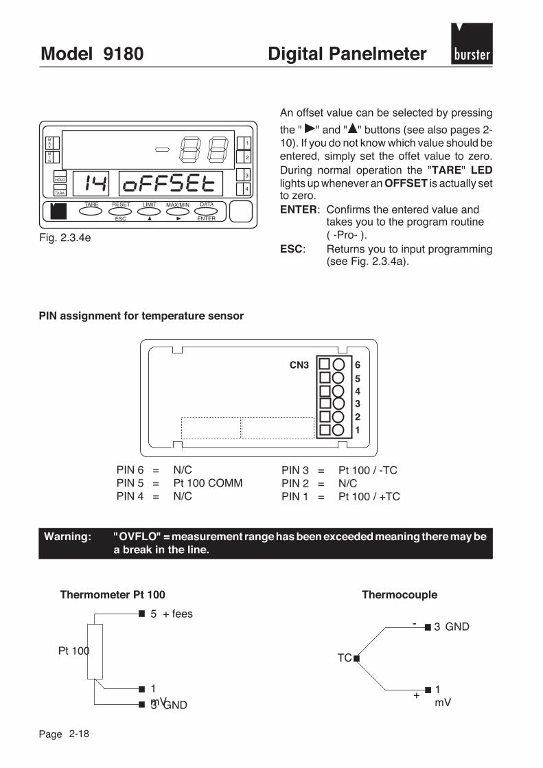
An offset value can be selected by pressing
the " " and " " buttons (see also pages 2-10). If you do not know which value should beentered, simply set the offet value to zero.During normal operation the "TARE" LEDlights up whenever an OFFSET is actually setto zero.ENTER: Confirms the entered value and
takes you to the program routine( -Pro- ).
ESC: Returns you to input programming(see Fig. 2.3.4a).
PIN assignment for temperature sensor
PIN 6 = N/CPIN 5 = Pt 100 COMMPIN 4 = N/C
PIN 3 = Pt 100 / -TCPIN 2 = N/CPIN 1 = Pt 100 / +TC
Warning: "OVFLO" = measurement range has been exceeded meaning there may bea break in the line.
Thermometer Pt 100 Thermocouple
5 + fees
1mV3 GND
Pt 100TC
3 GND
1mV
+
-

burster Digital Panelmeter Model 9180
Page
6543
21
POT
Type 9180
CN3 654321
2-19
2.3.5 Potentiometer
Bild 2.3.5a
MAX
MIN
1
HOLD
TARA
2
TARE RESET
ESC
LIMIT MAX/MIN DATA
ENTER
3
4
If you press "ENTER" in the program mode10 CnfInP (see Fig. 2.3c) you reach the inputprogramming routine 11 - 15. Should thedevice not be set to 15 -Pot-, press the " "button until the program routine 15 -Pot-appears.ENTER: Confirm with "ENTER" and the
device is configured as apotentiometer display and sendsyou to the program routine -Pro-.
ESC: Returns you to the programminglevel (-Pro-).
Pin assignment for the potentiometer
PIN 6 = Feed -PIN 5 = Feed +PIN 4 = N/C
PIN 3 = GroundPIN 2 = WiperPIN 1 = N/C
After assigning the input please refer to chapter 2.4 to set the measurement range.

Model 9180 bursterDigital Panelmeter
Page 2-20
2.4 Configuration of the display
2.4.1 Menu overview
2.4.2 Configurable parameters
Menu function Configurable parameters
21 - SCAL Enter sensor values: INPUT1 - DISPLAY1 - decimal point - INPUT2- DISPLAY2
22 - TEACH Teach in meas. signal: TEACH1 - DISPLAY1 - decimal point - TEACH2- DISPLAY2
23 - DISPLAY Brightness [high, low] - Fill display with zeros [Yes, No]
24 - FILTER Digital filter of the measurement signal [none, low, medium, high] -Display speed [high, low]
The following menu item only appears if the panelmeter has beenprogrammed as "LoAD" for strain gage sensor (DMS):
25 - ROUND Rounds of the display [1, 2, 5, 10, 20, 50 or 100 digit(s)].

burster Digital Panelmeter Model 9180
Page 2-21
2.4.3 Access to display settings
MAX
MIN
1
HOLD
TARA
2
TARE RESET
ESC
LIMIT MAX/MIN DATA
ENTER
3
4
Fig. 2.4a
Press the "ENTER" button again. The supplementary display shows 20 CnFdSP. Now you canperform the corresponding configuration using the submenus.You will find precise and detailled description of the SCAL and TEACH functions starting withpage 2-23.
Important: Before each calibration delete to zero any existing TARA values.To do this press TARE and RESET at the same time. First releaseTARE and then release RESET !
2.4.4 Programming the display for the correct measurementvariables
Programming the display for the correct measurement variables
The display can be programmed from -99999 up to 99999 for process signals, strain gagesensors (LoAD) and potentiometers. The thermometers do not need any programmng as theinput and measurement range are automatically set in accordance with the sensor type selected.Here the settings can only be corrected with "Offset" (see page 2-10).
To program the measurement range you must enter 2 input values (INPUT1, INPUT2) and2 output values (DISPLY1, DISPLAY2) in accordance with the two input values. The entry isautomatically completed by the decimal point setting.
Um in das Programm-Modul 20 zu gelangen, betätigen Sie "ENTER", danach zweimal die" " -Taste.

Model 9180 bursterDigital Panelmeter
Page 2-22
Climbing meas. range Falling meas. range
DISPLAY1(dSP2)
DISPLAY2(dSP2)
INPUT2(InP2)
1
2
INPUT1(nP1)
DISPLAY2(dSP2)
DISPLAY1(dSP1)
INPUT1(nP1)
1
2
INPUT2(nP2)
When programming the measurement range, first the input and output parameters are enteredin accordance with point 1, then the decimal point and finally the input and output parameterscorresponding to point 2.When programming the input the decimal point is automatically set to the position which permitsthe largest possible display. However, this can be adjusted manually.
The position of the decimal point must always be selected (equally applicable to both DISPLAY1and DISPLAY2) so that the best possible resolution is attained.
The instrument provides two programming methods: SCAL and TEACH.
The SCAL mode permits the entry of 5 parameters, 2 input values (INP1, INP2), the correspondingdisplay values (DSP1, DSP2) and the position of the decimal point. This is a very precise mannerof calibrating, if the output signals of the sensors are known exactly.
In TEACH mode you need to know which signal the sensor supplies. After connecting the sensorselect the TEACH function after reaching programming routine 20 CNfdSP. After pressing theENTER button 22-tCH1- appears and the sensor needs to shed its load or supplies a zero signal.Press ENTER again and then enter the ZERO POINT POSITION. Place the decimal point at thecorrect position and confirm with ENTER. 22-tCH2- appears in the display. Now set your sensorto nominal load or the end range and confirm by pressing ENTER. Now enter the end range forthe display and finish the routine by pressing ENTER. Pressing ENTER again stores the data.

burster Digital Panelmeter Model 9180
Page
MAX
MIN
1
HOLD
TARA
2
TARE RESET
ESC
LIMIT MAX/MIN DATA
ENTER
3
4
MAX
MIN
1
HOLD
TARA
2
TARE RESET
ESC
LIMIT MAX/MIN DATA
ENTER
3
4
MAX
MIN
1
HOLD
TARA
2
TARE RESET
ESC
LIMIT MAX/MIN DATA
ENTER
3
4
MAX
MIN
1
HOLD
TARA
2
TARE RESET
ESC
LIMIT MAX/MIN DATA
ENTER
3
4
2-23
2.4.5 Calibration by entering sensor data (SCAL)
Fig. 2.4d
Fig. 2.4d shows the SCAL menu, whichpermits scaling the display to the correctmeasurement quantity by entering sensordata (INP1, DSP1 and INP2, DSP2).
: Abandons SCAL item and goes toTEACH item (see page 2-24).
ENTER: Permits programming of the firstSCAL point (INP1).
ESC: Returns you to input programming(-Pro-).
By pressing the " " and " " buttons you can
set the first input value. Using the " " buttonthe position is changed one digit at a time,
while the " " button is used to jump to thenext digit. Proceed until you have the rightINP1 value.ENTER: Confirms the entry and go to the
next menu item (DSP1).ESC: Returns you to input programming
(-Pro-).Fig. 2.4e
Fig. 2.4f
By pressing the buttons " " and " " you canset the 1st display value. Now you proceed inthe same manner as described under Fig.2.4e.ENTER: Confirms the entry and takes you to
the next menu item (dECP).ESC: Returns you to input programming
(-Pro-).
Fig. 2.4g
The main display shows the programmedDSP1 value with flashing decimal point. Bypressing the " " button the point is moveduntil you reach the desired position.ENTER: Confirms the new position and takes
you to the next program routine.ESC: Returns you to input programming
(-Pro-).

Model 9180 bursterDigital Panelmeter
Page
MAX
MIN
1
HOLD
TARA
2
TARE RESET
ESC
LIMIT MAX/MIN DATA
ENTER
3
4
MAX
MIN
1
HOLD
TARA
2
TARE RESET
ESC
LIMIT MAX/MIN DATA
ENTER
3
4
MAX
MIN
1
HOLD
TARA
2
TARE RESET
ESC
LIMIT MAX/MIN DATA
ENTER
3
4
MAX
MIN
1
HOLD
TARA
2
TARE RESET
ESC
LIMIT MAX/MIN DATA
ENTER
3
4
2-24
Fig. 2.4h
By pressing the " " and " " buttons item 2(INP2) is selected.ENTER: Confirms the entry and takes you to
the next program routine.ESC: Returns you to input programming
(-Pro-).
Fig. 2.4i
2.4.6 Calibrate by means of TEACH-IN
By pressing the " " and " " buttons youselect the setting for DSP2.ENTER: Confirms the entry takes you from
the SCAL menu back to inputprogramming (-Pro-).
ESC: Returns you to input programming(-Pro-).
Fig. 2.4j
Fig. 2.4k
The actual signal of the sensor is displayed.ENTER: Confirms the first value (TCH1).ESC: Discards this value and returns you
to the TEACH routine (see Fig. 2.4j).
Fig. 2.4j shows the TEACH menu, whichpermits correct measurement quantity scalingof the display by teaching in the initial and endvalue (TCH1and TCH2) with thecorresponding display values (DSP1 andDSP). Selection of the menu with "ENTER".ENTER: Selects this menu and takes you to
the next program routine.ESC: Returns you to input programming
(-Pro-).

burster Digital Panelmeter Model 9180
Page
MAX
MIN
1
HOLD
TARA
2
TARE RESET
ESC
LIMIT MAX/MIN DATA
ENTER
3
4
MAX
MIN
1
HOLD
TARA
2
TARE RESET
ESC
LIMIT MAX/MIN DATA
ENTER
3
4
MAX
MIN
1
HOLD
TARA
2
TARE RESET
ESC
LIMIT MAX/MIN DATA
ENTER
3
4
MAX
MIN
1
HOLD
TARA
2
TARE RESET
ESC
LIMIT MAX/MIN DATA
ENTER
3
4
2-25
Fig. 2.4L
By pressing the " " and " " buttons you canset the 1st display value. Here the 1st digitflashes. Using the " " button, you can alterthe setting one digit at a time, with the " "button you jump to the next digit. Proceed inthis manner until you have set the right displayvalue.ENTER: Confirms the entry and takes you to
the next menu item (dECP).ESC: Returns you to input programming
(-Pro-).
Fig. 2.4o
Using buttons " " and " " the display valueis programmed which should be assigned tothe input signal INP2.ENTER: Confirms the entered value and
returns you to the input level inprogramming mode.
ESC: Returns you to input level inprogramming mode (-Pro-).
Fig. 2.4N
Fig. 2.4M
The main display shows the value learned inthe previous routine (DSP1) using a flashingdecimal point. Press the " " button severaltimes one after the other to set it to the desiredposition.ENTER: Confirms the selected position and
takes you to the next routine.ESC: Returns you to the input level in the
programming mode (-Pro-).
The sensor signal currently present at theinput appears in the main display. Press the"ENTER" button to confirm it as the inputvalue at the second input point (INP2).ESC: Press this button if you want to store
the value in the display and thenreturn to the beginning of menu 22(see Fig. 2.4j).

Model 9180 bursterDigital Panelmeter
Page
MAX
MIN
1
HOLD
TARA
2
TARE RESET
ESC
LIMIT MAX/MIN DATA
ENTER
3
4
MAX
MIN
1
HOLD
TARA
2
TARE RESET
ESC
LIMIT MAX/MIN DATA
ENTER
3
4
MAX
MIN
1
HOLD
TARA
2
TARE RESET
ESC
LIMIT MAX/MIN DATA
ENTER
3
4
2-26
2.4.7 Select display brightness
Fig. 2.4p
Fig. 2.4p shows the input level for menu dSP.In this menu the display brightness can beadjusted and the appearance of of the leadzeros suppressed in the display. Press"ENTER" to reach the programming mode ofthis parameter.ENTER: Takes you to the next programming
menu.ESC: Returns you to the input level in the
programming mode (-Pro-).
Fig. 2.4s
: Select YES to fill up the left placeswith zeros or NO for no leadingzeros.
ENTER: Confirms your selection andabandons the menu and returnsyou to the input level in programmingmode (-Pro-).
ESC: Returns you to the input level in theprogramming mode (-Pro-).
Fig. 2.4r
: Selects the brightness level of thedisplay [HI = high, LO = low].This effects and immediate changein brightness.
ENTER: Confirms the input value and takesyou to the next routine in the pro-gram, namely "Lead zeros".
ESC: Return to the input level in theprogramming mode (-Pro-).
2.4.8 Suppress leading zeros

burster Digital Panelmeter Model 9180
Page 2-27
MAX
MIN
1
HOLD
TARA
2
TARE RESET
ESC
LIMIT MAX/MIN DATA
ENTER
3
4
Fig. 2.4t shows the input level for the FILTmenu, in which a filter stage is entered for thesignal permitting you to select the displayspeed for the measurements. Press "ENTER"to gain access to the parameter programminglevel.ENTER: Press this button to go to another
programming menu for the display.ESC: Returns you to the input display for
programming (-Pro-).Fig. 2.4t
2.4.9 Select filter factors for measurement signals
Fig. 2.4u
MAX
MIN
1
HOLD
TARA
2
TARE RESET
ESC
LIMIT MAX/MIN DATA
ENTER
3
4
: Select filter stage measurementsignal,[NO = without filter,LO = low filter,MD = medium filter,HI = high filter]
ENTER: Confirms the entered data and takesyou to the programming level fordisplay speed.
ESC: Returns you to input programming(-Pro-).

Model 9180 bursterDigital Panelmeter
Page
MAX
MIN
1
HOLD
TARA
2
TARE RESET
ESC
LIMIT MAX/MIN DATA
ENTER
3
4
MAX
MIN
1
HOLD
TARA
2
TARE RESET
ESC
LIMIT MAX/MIN DATA
ENTER
3
4
MAX
MIN
1
HOLD
TARA
2
TARE RESET
ESC
LIMIT MAX/MIN DATA
ENTER
3
4
2-28
2.4.10 Select filter factors for the display
Fig. 2.4v
: Select filter stage for display.Select LO (low speed, = 0.5 s) or HI(high speed = 125 ms).
ENTER: Confirms the entered data, takesyou out of the FILT menu and overto the programming level (-Pro-).
ESC: Returns you to input display forprogramming (-Pro-).
2.4.11 Rounds of the display value
Fig. 2.4w
The Fig. shows the input level for the menulabelled "round". With this menu the valuedisplayed can be rounded. Press the "ENTER"button to program the rounding operation.
The main display shows the correspondingrounding steps by pressing the button:01 = adjusting the displayed measurementvalue in single increments, 02 = increments oftwo, 05 = increments of five, 10 = incrementsof ten, 20 = increments of twenty, 50 =increments of fifty or 100 = increments of onehundred. When the display indicates the rightvalue, press the "ENTER" button to store thevalue and quit the "round" menu automaticallyreturning to the input level in programmingmode (-Pro-).ESC: Return to the input level in the
programming mode (-Pro-) withoutsaving changes.
Fig. 2.4x
The menu permits the digital display to be set from single increment steps to increments ofup to 100.This menu item is only functional for DMS strain gage sensors (LoAD).

burster Digital Panelmeter Model 9180
Page 3-1
3. Controlling (HOLD, TARE, MAX/MIN, RESET)
3.1 Functions triggered via the keyboard
TARE Every time you press the "TARE" key, the value currently displayed is savedas a tare value and the display is set to zero.
To delete the tare memory, keep the "RESET" button pressed down and pressthe "TARE" key. First release the "TARE" key and then the "RESET" button.
If the device has been configured as a thermometer, this function cannot berealised. However, entering a temperature offset during input programminghas the same effect as the entering of a tare value with the "TARE" key.The "TARE" LED indicates that the device is operating with the tare value(oroffset value).Using the MAX/MIN button you can have the saved tare or offset valuedisplayed.
Disabling the It is possible to disable the "TARE" button so that the stored tare value cannotTARE function be changed. To do this disconnect the power from the device and install a
bridge between terminals 3 and 4 of the CN2 connection (see page 3-3).When the device is reconnected to power this function cannot be activated bythe keyboard.
RESET The "RESET" button is used together with the "TARE" or "MAX/MIN" buttonsto delete the memory of the Tare or Max or Min values. To do this RESET mustbe pressed at the same time as the corresponding button.
LIMIT In operating mode this button is only enabled when the device contains anoption for output control: 2 RELAYS, 4 RELAYS or 4 OPTOCOUPLERS (seepage 4-11).If you press the "LIMIT" button, programmed setpoints appear one after theother in the secondary display. L1, L2, L3 or L4 appear in the auxiliary displaydepending on the selected option. If it involves the 2 RELAYS option only thedisplay L1 and L2 appears.
The setpoints are displayed in sequence each time the "LIMIT" button ispressed, regardless of whether they are active or inactive. If you press thisbutton after the last setpoint is displayed, the secondary and auxilary displaysgo blank and the measured value appears in the display. While the setpointsare displayed, the other buttons remain operational.

Model 9180 bursterDigital Panelmeter
Page 3-2
MAX/MIN The "MAX/MIN" button is used to display the max., min., and tare (or offset)values. When the button is initially pressed the MAX value saved after theRESET button was last pressed, is displayed in the secondary display. HIappears in the auxiliary display. When the button is pressed a second time,the smallest MIN value appears with LO displayed.
If tare has been saved or a temperature offset value for thermometers,pressing the "MAX/MIN" buttom third time brings about a correspondingly"tared off" value or offset and TA or OF appear in the auxiliary display.
If you press the button a fourth time, the secondary and auxilary displays goblank.
The "MAX" and "MIN" LEDs in the upper left part of the display light up eachtime the device reads a higher value that the one in the maximum valuememory or a smaller value than the one in the minimum value memory. Thenew value replaces the previous one in the memory.
To delete the maximum and minimum memories you call up "MAX or MIN" inthe secondary display. Then keep the "RESET" button pressed down and atthe same time press "MAX/MIN". Release the buttons in the reverse order.
During display of the maximum or minimum value the other keys remainactive.
The functions TARE, MAX/MIN and RESET can be activated in the same manner via the CN2connection when using the keyboard.
The devices are equipped with optocoupled functional inputs, which can be activated externallyvia contacts or logical operating states.
Input to ground (PIN 3) = FUNCTION ACTIVATED
3.2 Functions triggered via the input

burster Digital Panelmeter Model 9180
Page 3-3
HOLD The HOLD function responds to the Low signal at PIN 2.Ground reference point is Pin 3.
If you activate HOLD the display value is frozen as long as Pin 2 is applied toground. The "HOLD" LED indicates that HOLD is active. This status influencesneither the internal functioning of the device nor the setpoint outputs, but theanalog and the BCD output (is frozen).
CN21 2 3 4 5
CN21 2 3 4 5
-
+
HOLD has the Display: is frozenfollowing effects: Analog output: is frozen
BCD output: is frozenRS232/485: transmits frozen measurement valueGW outputs: switches with current measurement value
The HOLD function is active if PIN 2 of the CN2 connection is connected with respect to ground(PIN 3). In the tabletop version this corresponds to PIN 4 (HOLD) and PIN 5 (ground). The PINassignment for the tabletop housing can be found on page 5-1.
Example for HOLD activation
The controlling electronics connected to the inputs of the CN2 connection must withstanda potential of 40 V and 20 mA with respect to ground.
CN21 2 3 4 5
PIN 1 = RESETPIN 2 = HOLDPIN 3 = GROUNDPIN 4 = TAREPIN 5 = MAX/MIN

Model 9180 bursterDigital Panelmeter
Page 3-4
Internal input circuit in the case of RESET:
+ 25 (intern)
9180
1RESET
MASSE3

burster Digital Panelmeter Model 9180
Page 4-1
4. Output options
The type 9180 can be equipped with one or more options for control and communication:
burster RetrofitOption device code with
(default ex works) option possible
RS232C 9180-VXX1X 9180-Z0010RS485 9180-VXX2X 9180-Z0020BCD output TTL/24 V 9180-V0X3X 9180-Z0030
Analog output 4-20 mA, 0-10 V 9180-VX1XX 9180-Z01002 Grenzwert-Relais 8 A 9180-VXXX1 9180-Z00014 Grenzwert-Relais 0,2 A 9180-VXXX2 9180-Z00024 Grenzwert-Transist. open C. n-schaltend 9180-VXXX3 9180-Z00034 Grenzwert-Transist. open C. p-schaltend 9180-VXXX4 9180-Z0004
All of the named options are optocoupled with respect to the input signal. They can easily beconnected to the base plate using the connecters. They are recognised by the device as soonas they are installed. As a rule these options are factory-installed by the manufacturer. But aretrofitting is possible at any time. See above for the order code for optional printed circuit boards!

Model 9180 bursterDigital Panelmeter
Page 4-2
In the figure below the individual slots for the output options are depicted.The options 2RE, 4RE and 4OP respectively can only be plugged into the M5 slot.The options RS2 and RS4 respectively can only be plugged into the M1 slot.Slot M4 is provided for ANA options.
The following 3 options can be installed at the same time:
Analog outputRS232C or RS485 (only one)2 relays, 4 relays or 4 optos (only one)
The BCD output can only be operated individually. This is connected directly to the main printedcircuit board using an 18 pin flatband cable.
The device equipped with RS232C or RS485 can be programmed with a PC using theRSKOSMOS software.
burster Digital Panelmeter Model 9180
Page 4-3
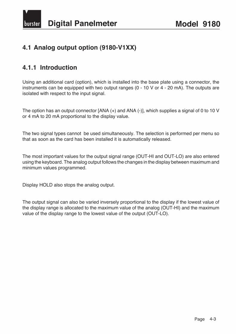
4.1 Analog output option (9180-V1XX)
4.1.1 Introduction
Using an additional card (option), which is installed into the base plate using a connector, theinstruments can be equipped with two output ranges (0 - 10 V or 4 - 20 mA). The outputs areisolated with respect to the input signal.
The option has an output connector [ANA (+) and ANA (-)], which supplies a signal of 0 to 10 Vor 4 mA to 20 mA proportional to the display value.
The two signal types cannot be used simultaneously. The selection is performed per menu sothat as soon as the card has been installed it is automatically released.
The most important values for the output signal range (OUT-HI and OUT-LO) are also enteredusing the keyboard. The analog output follows the changes in the display between maximum andminimum values programmed.
Display HOLD also stops the analog output.
The output signal can also be varied inversely proportional to the display if the lowest value ofthe display range is allocated to the maximum value of the analog (OUT-HI) and the maximumvalue of the display range to the lowest value of the output (OUT-LO).

Model 9180 bursterDigital Panelmeter
Page 4-4
4.1.2 Installing the card
1. Take the electronics out of the housing and open the location on the housing marked in Fig.1 (arrow).
This opening is set up for the analog output. The option card is installed in slot M4.
2. Lightly press the tip of the card into the seat of the base plate until it latches in.If vibrations arise when using the device it might make sense to solder the card onto the baseplate at the corresponding lashes.
Before inserting the device back into its housing you should check to see if access to theprogramming level is not disabled (See page 2-5 concerning the DIP switch).

burster Digital Panelmeter Model 9180
Page 4-5
4.1.3 Terminals
Each connection card is supplied with a sticker or label on which the terminals are depicted (seeFig. 4.1.3a).
Fig. 4.1.3 a: Sticker for options
ANA analog outputsConnection CN4PIN 2 = (+) 0-10 V / 4-20 mAPIN 1 = (-) 0-10 V / 4-20 mAFig. 4.1.3 b: Rear side of the device
withconnection for ANA option
4
CN 7
56
2 RL
NO 2CM 2NC 2
4 RL
RL 4N.C.COMM
40 P
OP 4N.C.COMM
1
CN 6
23
2 RL
NO 1CM 1NC 1
4 RL
RL 1RL 2RL 3
40 P
OP 1OP 2OP 3
1
CN 4 ANALOG OUTPUT
2(-)(+) 0-10 V/4-20 mA
CN 5GNDRXTXRTS
4321
RS232CGNDABN/C
RS485

Model 9180 bursterDigital Panelmeter
Page 4-6
4.1.4 Technical data
Output 0-10 V Output 4-20 mAResolution 12 bit 12 bitPrecision 0.1 % F.E. ± 1 bit 0.1 % F.E. ± 1 bitReaction time 60 ms 60 msThermal drift 0.2 mV/°C 0.5 µA/°CImpedance ≥ 500 Ω ≤ 800 Ω
4.1.5 Programming guidelines
Module 40 - analog output
The figure shows the entire menu of module 40 for the configuration of the analog output. Thisappears only after the corresponding option has been installed. The module has at its disposal3 independent access menus, with which the following parameters can be determined:
Menu 41 -tYPE- : For selection of the analog type (0-10 V or 4-20 mA).Menu 42 -SCAL- : Allocates the display values for the range of the
output signal.Menu 43 -FILt- : For selection whether the change in output should be
a function of the display (filter ON) or the input signal(filter OFF).

burster Digital Panelmeter Model 9180
Page
MAX
MIN
1
HOLD
TARA
2
TARE RESET
ESC
LIMIT MAX/MIN DATA
ENTER
3
4
MAX
MIN
1
HOLD
TARA
2
TARE RESET
ESC
LIMIT MAX/MIN DATA
ENTER
3
4
MAX
MIN
1
HOLD
TARA
2
TARE RESET
ESC
LIMIT MAX/MIN DATA
ENTER
3
4
4-7
4.1.6 Access for programming the analog output
Fig. 4.1.6
By pressing the "ENTER" key you gofrom operation to programming mode (Dis-play -Pro-).Then keep pressing the " "key until you are in level 40.Press "ENTER" to reach the first menu or
: To go to the next programmingmode
ESC: To return to the input level ofprogramming mode (-Pro-).
Fig. 4.1.6.1a
Fig. 4.1.6.1b
With the " " key you can select the outputsignal type ("Udc" for 0-10 V and "Idc" for4 - 20 mA). If the desired output typeappears in the display, press "ENTER" toconfirm and return to programming mode(Display -Pro-).ESC: Returns you to the -Pro- mode
without saving.
4.1.6.1 Selecting the output signal type
Starting from level 40 with the pressing of"ENTER" there appears on the display theinput display of menu 41 (Fig. 4.1.6.1a), -Udc- for 0 - 10 V or -Idc- for 4-20 mA). Ifthe desired output signal type appears,press the " " key to go into the menu forthe scaling of this signal type (Fig. 4.1.6.2a).ENTER: If you would like to change the
output signal type, press"ENTER" again. The twohyphens disappear and thedevice is ready for signal typeselection using the " " key.
ESC: Returns you to the input level ofprogramming mode (Display-Pro-).

Model 9180 bursterDigital Panelmeter
Page
MAX
MIN
1
HOLD
TARA
2
TARE RESET
ESC
LIMIT MAX/MIN DATA
ENTER
3
4
MAX
MIN
1
HOLD
TARA
2
TARE RESET
ESC
LIMIT MAX/MIN DATA
ENTER
3
4
MAX
MIN
1
HOLD
TARA
2
TARE RESET
ESC
LIMIT MAX/MIN DATA
ENTER
3
4
4-8
4.1.6.2 Scaling
Fig. 4.1.6.2a
Fig. 4.1.6.2b
If starting from the level in Fig. 4.1.6, youpress "ENTER" once and " " once, youobtain the display appearing in Fig.4.1.6.2a. This is the input level to menu 42in which the display values are allocatedfor the range of the analog output.Press "ENTER" to carry out programmingof this parameter or
: to go to the next configurationmenu (Fig. 4.1.6.3a)
ESC: To reach the input level ofprogramming mode (-Pro-)
Fig. 4.1.6.2c
Repeat the previously describedprocedure (keys " " and " ") to programthe display value for the minimum value ofthe output (0 V or 4 mA).ENTER: Confirms the entry and takes
you to the input level ofprogramming mode (Display -Pro-).
ESC: Returns you to the input level ofprogramming mode (-Pro-).
Fig. 4.1.6.2b shows the programmingroutine, in which the display value is ente-red corresponding to the maximum valueof the output signal (10 V or 20 mA,depending on the type of signal). The sign- digit of the output value flashes so thatyou can adjust it by pressing the " " key.To reach the next digit press the " " key.Repeat this process until the desired valueappears in the display. Press "ENTER" tosave this entry and go to the nextprogramming routine.ESC: Returns you to the input level of
programming mode (-Pro-).

burster Digital Panelmeter Model 9180
Page 4-9
4.1.6.2.1 Configuration of the unipolar analog outputfor bipolar sensor signals
In the display of type 9180 there is only a unipolar analog output available. To completelyreproduce the signal range of bipolar sensors on the analog output, its zero point must be shiftedaccordingly.
Example: The measurement range of a 8524-6001 force sensor (± 1000 N) should becompletely reproduced on the 4 - 20 mA analog output of the display.
The following linear classification should be achieved:
- 1000 N →→→→→ 4 mA0 N →→→→→ + 12 mA
+ 1000 N →→→→→ + 20 mA
Configuration steps:
1. In the configuration level 40 alternate between AinAout**(check German)**2. Scroll to menu 42 SCAL3. Scroll to out - HI4. Under item out - HI the display value is entered which should be allotted to the range end
of the analog output (+20 mA). In the example, +1000 is entered. Confirm by pressing"ENTER". out - Lo appears.
5. Under out - Lo the display value is now entered which should be allotted to the range startof the analog output (4 mA). In the example, -1000 is entered.
Here the zero point for the force automatically lies in the middle of the analog range (at 12mA in the example).
-1000 N 0 +1000 N
4 mA
12 mA
20 mA IA
Model 9180 bursterDigital Panelmeter
Page
MAX
MIN
1
HOLD
TARA
2
TARE RESET
ESC
LIMIT MAX/MIN DATA
ENTER
3
4
MAX
MIN
1
HOLD
TARA
2
TARE RESET
ESC
LIMIT MAX/MIN DATA
ENTER
3
4
4-10
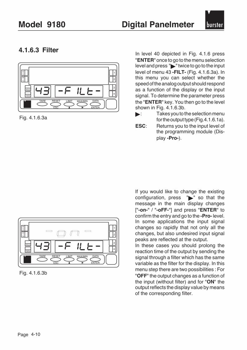
4.1.6.3 FilterIn level 40 depicted in Fig. 4.1.6 press"ENTER" once to go to the menu selectionlevel and press " " twice to go to the inputlevel of menu 43 -FILT- (Fig. 4.1.6.3a). Inthis menu you can select whether thespeed of the analog output should respondas a function of the display or the inputsignal. To determine the parameter pressthe "ENTER" key. You then go to the levelshown in Fig. 4.1.6.3b.
: Takes you to the selection menufor the output type (Fig.4.1.6.1a).
ESC: Returns you to the input level ofthe programming module (Dis-play -Pro-).
Fig. 4.1.6.3a
Fig. 4.1.6.3b
If you would like to change the existingconfiguration, press " " so that themessage in the main display changes["-on-" / "-oFF-"] and press "ENTER" toconfirm the entry and go to the -Pro- level.In some applications the input signalchanges so rapidly that not only all thechanges, but also undesired input signalpeaks are reflected at the output.In these cases you should prolong thereaction time of the output by sending thesignal through a filter which has the samevariable as the filter for the display. In thismenu step there are two possibilities : For"OFF" the output changes as a function ofthe input (without filter) and for "ON" theoutput reflects the display value by meansof the corresponding filter.

burster Digital Panelmeter Model 9180
Page 4-11
4.2 Options - limit value outputs - 2 relays (9180-VXXX1), 4 relays (9180-VXXX2) and 4 optocouplers ( 9180-VXXX3)
4.2.1 Introduction
The instrument can be extended with an option for 2 or 4 limit value outputs. This provides it withalarm and control functions.
All switching points have a time delay, which are programmed using a timer circuit (in seconds)or a symmetrical or asymmetrical hysteresis. Furthermore the limit value functions can also bedisabled. Additionally it is possible to configure the alarm so that it functions independently (eachalarm is activated by its switching point) or so that its activation depends on another alarm. Herethe latter function is designated TRAC.
The options are supplied in the form of plug-in cards. As a rule these cards are already pre-installed at the factory.
The following plug-in cards are available:
Individual option Device with optionpcbs pcbs installed
2RE: 2 relays, with 8 A 9180-Z0001 9180-VXXX14RE: 4 relays, with 0.2 A 9180-Z0002 9180-VXXX24OP: 4 optocouplers type NPN 9180-Z0003 9180-VXXX3
4OPP: 4 optocouplers type PNP 9180-Z0004 9180-VXXX4

Model 9180 bursterDigital Panelmeter
Page 4-12
4.2.2 Function description
To guarantee adaptation to customer-specific requirements, the limit value alarm can beactivated individually or in various combinations.
1. Independent alarmsIndependent alarms are triggered if the display value reaches the switching point valueprogrammed by the user.
For the programming of this kind of alarm you also have to determine the followingparameters:
a. Activiating mode HI/LOIn "HI" mode the output is activated if the display value exceeds the value of the switchingpoint. In the "LO" mode the output is activated if the display value drops below the value ofthe switching point.
b. Time delay or hysteresisAll alarms can be provided with a switching delay or hysteresis. The switching delaycommences, when the display value exceeds or drops below a fixed value. There are twopossibilities when using time delay with hysteresis: the asymmetrical hysteresis delaysthe deactivation side of the output while the symmetrical hysteresis affects both sides of theswitching point.The switching delay can be programmed in seconds from 0 up to a maximum displayablevalue.The hysteresis can be programmed in points within the entire display range. The positionof the decimal point is determined by the previously set scaling parameter.
Figures 4.2.2a and 4.2.2b show the time delay realized by the timer circuit (dly) and by theasymmetrical hysteresis (hys-1) of two alarms (SET1 and SET2). They are programmed for theactivation in the respective modes HI (OUT1) and LO (OUT2).
hys-1
hys-1SET1
SET2
OUT1
OUT2
dly dly
dly dly
SET1
SET2
OUT1
OUT2
Fig. 4.2.2a Switching delay Fig. 4.2.2b A s y m m e t r i c a lhysteresis

burster Digital Panelmeter Model 9180
Page 4-13
Fig. 4.2.2c shows the time delay realized using symmetrical hysteresis. For the sake of simplicityonly one alarm is displayed in HI and LO mode.100 % of the selected hystereses (hys-2) are added to both sides of the switching point so thatone band arises within which the output is activated (HI mode) or deactivated (LO mode) ist. Theswitching delay with symmetrical hystersis is helpful for processes where the alarm should onlybe triggered between two specific points.
SEThys-2
hys-2 hys-2hys-2
OUT(HI mode)
OUT(LO mode)
SET1
SET3
TRACK2
TRACK4
OUT1
OUT2
OUT3
OUT4
Fig. 4.2.2c Symmetrical hysteresis
Fig. 4.2.2d

Model 9180 bursterDigital Panelmeter
Page 4-14
2. Logically combined alarmsThe switching points SET2 and SET4 can be combined by means of programming with thecorresponding switching points SET1 and SET3. This kind of alarm is not triggered bycomparison of the previously programmed display value, but by the comparison to the valueused to trigger the combined alarm.
When programming this alarm, the value of the first switching point is set (for exampleSET1 = 200) and the interval (Offset) determined between this and the second alarm (forexample TRACK2 = 50). Even if the value of SET1 changes, alarm 2 is always triggered50 points above SET1. If a negative value is programmed (-50), alarm 2 is activated 50points under SET1. Fig. 6.8.2d shows an example for a positive (TRACK2) and a negative(TRACK4) logic combination.
3. Correction of excess volumesDue to mechanical factors and assembly, for certain measurements, particularly forweighing and dosing, it is not possible to stop an operation precisely at a certain point(reaction time, "weight in fly"- effect).
The "weight in fly"- effect arises when filling vessels. In this process a flow inlet valve isclosed via an alarm upon reaching a programmed value. However, as there can still beresidual material in the pipe or in the air when the alarm is triggered, the desired filling levelis exceeded in the vessel.
The function AUTO TRAC is particularly designed to correct these excess volumes. Thisfunction is based on controlling the volume which exceeds the programmed amount ormeasure. To obtain the desired end value, the alarm is triggered with the excess amounttaken into account.
Only the SET2 alarm is equipped with an "AUTO TRAC" function. Here SET1 is the setalarm.To perform the "AUTO TRAC" function the desired switching point value is programmed inSET1. SET2 is automatically programmed as the logically combined alarm (initially it hadthe same value as SET1).
SET1 = desired switching point valueSET2 = AUTO TRAC
If the value of SET1 is reached, output 1 interrupts the process, but the filling volume risesto a value which is registered as the maximum value.
The measured maximum value is compared to the set value and the difference between thetwo is saved as the TRAC value and deducted from SET2. The value of SET2 is thussomewhat smaller than that of SET1. During the next measurement SET2 interrupts theprocess so that the effective end volume approximately corresponds to the programmedvalue in SET1.This process is updated in the following measurements.

burster Digital Panelmeter Model 9180
Page 4-15
4.2.3 Terminals
4
CN 7
56
2 RE
NO 2CM 2NC 2
4 RE
RL 4N.C.COMM
40 P
OP 4N.C.COMM
1
CN 6
23
2 RE
NO 1CM 1NC 1
4 RE
RL 1RL 2RL 3
40 P
OP 1OP 2OP 3
1
CN 4 ANALOG OUTPUT
2(-)(+) 0-10 V/4-20 mA
CN 5GNDRXTXRTS
4321
RS232CGNDABN/C
RS485
Label for options
CN7 CN6
NO
NC
REL2 REL1
4
5
6
1
2
3
NO
NC
CN7 CN6
COMM
REL14
5
6
1
2
3
REL4
REL2
REL3
CN7 CN6
COMM
OP14
5
6
1
2
3
OP4
OP2
OP3
CN7 CN6
COMM
OP14
5
6
1
2
3
OP4
OP2
OP3
9180-VXXX1 or 9180-Z00012RE - OPTION 2 RELAYSPIN 4 = NO 2 PIN 1 = NO 1PIN 5 = COMM 2 PIN 2 = COMM 1PIN 6 = NC 2 PIN 3 = NC 1
9180-VXXX2 or 9180-Z00024RE - OPTION 4 RELAYSPIN 4 = RL 4 PIN 1 = RL 1PIN 5 = N/C PIN 2 = RL 2PIN 6 = COMM PIN 3 = RL 3
9180-VXXX3 or 9180-Z00034OP - OPTION 4 NPN OPTOCOUPLERSPIN 4 = OP 4 PIN 1 = OP 1PIN 5 = N/C PIN 2 = OP 2PIN 6 = COMM PIN 3 = OP 3
9180-VXXX4 or 9180-Z00044OPP - OPTION 4 PNP OPTOCOUPLERSPIN 4 = OP 4 PIN 1 = OP 1PIN 5 = N/C PIN 2 = OP 2PIN 6 = COMM PIN 3 = OP 3
Rearside of the basic unitwith output optionRELAY/OPTOCOUPLER
4
56
1
23
Note:If the relays are operated with an inductiveload, we recommend connecting an RCnetwork to the terminals of the coil orcontacts.

Model 9180 bursterDigital Panelmeter
Page 4-16
4.2.4 Technical specifications
Technical data Option 2RE Option 4REMax. current 8 A 0,2 AMax. power 2000 VA / 192 W 25 VA / 10 WMax. voltage 250 VAC / 150 VDC 250 VAC / 50 VDCContact resistance max. 3 mΩ max. 200 mΩSwitching delay max. 10 ms max. 6 ms
Option 4OP Option 4OPPMax. voltage 50 VDC 50 VDCMax. current 50 mA 50 mALeakage current 100 µA (max.) 100 µA (max.)Reaction time 1 ms (max.) 1 ms (max.)
4.2.5 Programming instructions

burster Digital Panelmeter Model 9180
Page
MAX
MIN
1
HOLD
TARA
2
TARE RESET
ESC
LIMIT MAX/MIN DATA
ENTER
3
4
4-17
4.2.6 Setting limit values
DefinitionThe flow chart on page 4-16 (programming instructions) corresponds to module 30 for programmingswitching points for equipment versions 9180-VXXX1, 9180-VXXX2 and 9180-VXXX3. If youonly have the option with 2 relays (9180-VXXX1) at your disposal, only menus 31 and 32 appearfor switching points SET1 and SET2.
Each switching point is programmed individually. If the programming of a switching point iscompleted, you can again access module 30 by pressing the "ENTER" key again (the message-Pro- appears in the secondary display) to configure the remaining switching points.
The flow chart shows that the switching points SET1 and SET3 are activated independently ofeach other, while switching points SET2 and SET4 can be activated in isolation as well as inmutual dependency. In this case SET2 is dependent on SET1 and SET4 is dependent on SET3.Switching point 2 is also equipped with an automatic track function.
Access to programming the switching pointsPress "ENTER" to go from the operating mode to the programming mode. Press the " " threetimes to reach level 30 Fig. 4.2.6a.
Fig. 4.2.6a
Information regarding the program flow chart (Page 4-16)As programming of the 4 switch points (page 4-18) as independent alarms is identical, thenumbers of the switch points in the figures were replaced by the symbol "#" so that these stepsapply for all switching points.When programming switching points 2 and 4 the options "ON" or "TRAC" (see Fig. 4.2.6c) leadto different subroutines. Each of these programs is dealt with individually on page 4-18.
Press "ENTER" again and the message "31-SET1" appears in the display for entry intothe programming menu switch point 1. Youare now on the switch point selection level.By pressing " " you can configure the nextswitching point.

Model 9180 bursterDigital Panelmeter
Page
MAX
MIN
1
HOLD
TARA
2
TARE RESET
ESC
LIMIT MAX/MIN DATA
ENTER
3
4
MAX
MIN
1
HOLD
TARA
2
TARE RESET
ESC
LIMIT MAX/MIN DATA
ENTER
3
4
MAX
MIN
1
HOLD
TARA
2
TARE RESET
ESC
LIMIT MAX/MIN DATA
ENTER
3
4
MAX
MIN
1
HOLD
TARA
2
TARE RESET
ESC
LIMIT MAX/MIN DATA
ENTER
3
4
4-18
The adjacent figure shows the input routinein the configuration menu for one of theoutputs. The symbol "#" stands for the numberof the switching point to be programmed. Toselect a different switching point, keeppressing " " until the desired numberappears.ENTER: Gives you access to programming
the selected switching point.ESC: Returns you to the input level
(Display -Pro-)
Fig. 4.2.6b
Bild 4.2.6e
By pressing "OFF" the alarm output isdeactivated again.
With the " " key you go to the display correspondingto the desired option and then press "ENTER".
Use the " " key to select "ON" and activatethe alarm outputs.Confirm by pressing "ENTER" and themessage in Fig. 4.2.6f appears in the display.Set the desired limit value. Then define thesignal status of the output (HI or LO) as wellas time delay and hysteresis.
Fig. 4.2.6c
Fig. 4.2.6d
The "TRAC" function can only be activatedfor switching point 2 (SET2) and switchingpoint 4 (SET4).Select this option to program the switch pointas "Tracking Alarm" either manually orautomatically.The next routines are described on page4-20.

burster Digital Panelmeter Model 9180
Page
MAX
MIN
1
HOLD
TARA
2
TARE RESET
ESC
LIMIT MAX/MIN DATA
ENTER
3
4
MAX
MIN
1
HOLD
TARA
2
TARE RESET
ESC
LIMIT MAX/MIN DATA
ENTER
3
4
MAX
MIN
1
HOLD
TARA
2
TARE RESET
ESC
LIMIT MAX/MIN DATA
ENTER
3
4
4-19
If you have selected "ON"
Fig. 4.2.6f
With " " and " " the desired value of theswitching point is programmed between-99999 and +99999.ENTER: Confirms the entered value and
switches you to HI or LOselection.
ESC: Returns you to the input level ofprogramming mode (Display-Pro-)
Fig. 4.2.6h
: The secondary display shows 3time delay modes for the output:"DLY" = time delay, "HYS1" =asymmetrical hysteresis or"HYS2" = symmetricalhysteresis (see page 4-12ff).
ENTER: If you are in the desired mode,press "ENTER" to confirmselection and program thenumerical value of the timedelay.
ESC: Returns you to the input level ofprogramming mode (Display-Pro-)
Fig. 4.2.6g
: Selection of "HI" leads toactivation of the output abovethe switching point or "LO" foractivation below the switchingpoint
ENTER: Confirms the selection and takesyou to the programming of theswitch delay
ESC: Returns you to the input level ofprogramming mode (Display-Pro-)

Model 9180 bursterDigital Panelmeter
Page
If "TRAC" has been selected(see also page 4-14)
MAX
MIN
1
HOLD
TARA
2
TARE RESET
ESC
LIMIT MAX/MIN DATA
ENTER
3
4
MAX
MIN
1
HOLD
TARA
2
TARE RESET
ESC
LIMIT MAX/MIN DATA
ENTER
3
4
4-20
Fig. 4.2.6i
Using the " " and " " keys the time delayvalue is programmed in seconds (from 0up to 99999, decimal point is optional, iftime delay was selected in the previoustime delay routine or two decimal points ifhysteresis was previously selected).ENTER: Confirms the entry and takesyou to the -Pro- display.
If the programmed hysteresis isgreater than the switching point,then the message ERRORappears when you press ENTERand the display goes to zero.The first digit flashes and a newvalue can be entered.
Fig. 4.2.6j
Only switching points SET2 and SET4 areprovided with the "TRAC" function.In this routine from menu 32 there are 2possibilities:Manual programming of the alarm valueSET2 (here "SET" is selected manually)or the required value is determined by theprocess (select "AUTO" = automatically)ENTER: If you have selected "AUTO",
pressing "ENTER" returns youto the input level of programmingmode (Display -Pro-). If you haveselected "SET", pressing"ENTER" takes you to the nextmenu level (Fig. 4.2.6k), in whichthe value of SET2 can beprogrammed.
ESC: Returns you to the input level forprogramming (Display -Pro-)

burster Digital Panelmeter Model 9180
Page
4.2.7 Display of the limit value settings in operating mode
To register alarm status the device is equipped with 4 LED displays in the right hand section of thedisplay. The LEDs are numbered from 1 to 4 (but for the 2RE option only the first two are used).The programmed switching point values can be displayed by pressing the "LIMIT" key (also with timedelay) during normal operation of the device.The switching point value is displayed in the secondary display while the letter "L" appears in theauxiliary display, followed by the number of the corresponding switching point.
The switching points are displayed by pressing the "LIMIT" button in sequence.When exceeding the nominal range (OVFLO), all of the outputs and LED displays corresponding tothe switching points are deactivated.
MAX
MIN
1
HOLD
TARA
2
TARE RESET
ESC
LIMIT MAX/MIN DATA
ENTER
3
4
MAX
MIN
1
HOLD
TARA
2
TARE RESET
ESC
LIMIT MAX/MIN DATA
ENTER
3
4
4-21
Program the value of the switching pointwith aid of the " " and " " keys.Remember that SET2 is logicallycombined with SET1 and SET4 with SET3.ENTER: Confirms your entry and
automatically takes you to theinput level of programming mode(-Pro-).
ESC: Returns you to the input level ofprogramming mode (Display-Pro-)
Fig. 4.2.6k

Model 9180 bursterDigital Panelmeter
Page 4-22
4.3 RS232 (RS2) option
4.3.1 Introduction
The output option RS232C consists of an additional card (reference RS2), which is installed inthe M1 plug-in slot.The card has a 4-way telephone connection (Western socket).
The RS232 output can be used to establish a communications line with which a master canrequest from one or more display instruments data, for example, display value, switching point,maximum and minimum values, tare values (or offset in the case of a thermometer). Furthermore,various functions can be performed like tare, deletion of the memory for maximum, minimum andtare values and changes to the switching points.
Furthermore the instrument is provided with a command with which all the equipment settings canbe copied into a different device of the same type.The transmission speed can amount to 1200, 2400, 4800 or 9600 baud. The device adressingis programmable between 00 and 99.
Using the RS232C option you can connect the device to a master unit using the RS232Cinterface.The operating mode is semi-duplex. The series channel is only active, if the device, which isnormally in receiving mode until the message arrives, is in operating mode.
If the device receives a valid message, an action can immediately be performed (tare in display,deletion of the maximum/minimum value or tare memory, change of switching points) or aresponse of the polled device can be transmitted (display value, value of a switching point or themaximum/minimum value or tare memory). The transmission of the display value can berequested using an external switch(see page 4-28).
4.3.2 Protocol and commands
Two communication types are provided for: the DITEL mode operates with a simple protocol.Using the ISO mode corresponding to the ISO 1745 standard, communication can be performedmore effectively in an environment prone to distortion, as here the validity of a message is testedduring transmission as well as reception.As the depicted in the function table on page 4-24, the DITEL Protocol works with 1 or 2 bytesdepending on the type of command, while the ISO 1745 protocol always requires two bytes percommand.
A example in BASIC in SOURCE CODE you can findat the end of this manual.

burster Digital Panelmeter Model 9180
Page 4-23
DITEL protocol
Format: 1 start bit, 8 data bits, 1 stop bit, no parity bit (none)
Receiving messagesA message transmitted to a device must consist of a sequence of ASCII codes:
D d C C X ........................................X CR
Symbol "" [ASCII 42] signifies the start of the message. Two address bytes between 00 and 99 ( D = tens digit, d = ones digit ). One or two ASCII codes (CC) for the desired command according to the function table on
page 4-24.If it involves a command to change parameters, the new value is transmitted in the form of asymbol byte "" [ASCII 43] or -[ASCII 45], followed by a block of n-ASCII codes including decimalpoint.Symbol "CR" [ASCII 13] signifies end of message.
Transmitting messagesThe format of messages transmitted from a device as a response to a data requestcommand is transmitted as follows:
SP X ........................................X CR
One byte for a space [ASCII 32]. A text (desired value) consisting of a symbol byte [ASCII 43] or - ]ASCII 45] followed by a block
of n-ASCII codes including decimal point. Symbol "CR" [ASCII 13] signifies end of message.
If it involves instructions or commands for change of parameters the device does not respond.

Model 9180 bursterDigital Panelmeter
Page 4-24
Protocol ISO 1745
Format: 1 start bit, 7 data bits, 1 stop bit, parity even
Transmitting a message to the deviceA message from the master unit must consist of the following code sequence:
SOH D d STX C C X ............... X ETX BCC
One SOH byte for the beginning of the message [ASCII 01]. One byte for the significance 10 and one byte for the significance 1 of the addresses of the device
being transmitted to. One STX byte for text beginning [ASCII 02]. Two command bytes according to the function table. For commands regarding parameter changes, a block of n-bytes for the numerical value
including the decimal point.
Function table
Command Function Function TypeDITEL ISO
V 0V Transmission of the min. memory contents
P 0P Transmission of the max. memory contents
T 0T Transmission of the TARE memory contents(Offset in the case of thermometers)
D 0D Transmission of the display value
L1 L1 Transmission of the switching point value 1
L2 L2 Transmission of the switching point value 2
L3 L3 Transmission of the switching point value 3
L4 L4 Transmission of the switching point value 4
v 0v Deletion of the min. value memory
p 0p Deletion of the max. value memory
r 0r Deletion of the tare memory
t 0t Acceptance of the display value as tare
M1 M1 Change switching point 1
M2 M2 Change switching point 2
M3 M3 Change switching point 3
M4 M4 Change switching point 4
Change
Parameters
Instructions
Request
Data

burster Digital Panelmeter Model 9180
Page 4-25
One ETX byte for end of text [ASCII 03]. One BCC control byte is computed as follows:
When executing an Exclusive-OR operation for all bytes between STX (not included) and ETX(included)
- If the byte in ASCII code lies at ≥ 32 it can be used as a BCC control byte.- If the byte in ASCII code lies at < 32 you obtain the BCC control byte by adding 32.
Receiving messages from the deviceThe typical message format, which the device supplies as a response to a command,appears as follows:
1. Commands which require a value:
SOH D d STX X ............... X ETX BCC
One SOH byte for the beginning of a message [ASCII 01]. 2 address bytes. One STX byte for text beginning [ASCII 02]. n-bytes corresponding to the desired value (including symbols and decimal point). One ETX byte for end of text [ASCII 03]. One BCC control byte computed in accordance with the information above.
If the master unit transmits a message to the address 00, the command is interpreted by all the devicesin the network and no response is obtained.
2. Commands requiring no value:
D d ACK or D d NAK
The device transmits an acknowledgement that the message has been received.
If the message was not correctly received and interpreted, the response consists of two addressbytes and one "ACK" byte [ASCII 06].
If the received message was not recognized and errors have arisen, the response consists oftwo address bytes and one "NAK" byte [ASCII 21].
If the master unit transmits a message to the address 00, the command is interpreted by all the devicesin the network and a response is obtained.

Model 9180 bursterDigital Panelmeter
Page 4-25
Fig. 4.3.3a
Out
put o
ptio
n R
S23
2C
4.3.3 Installation of the card
Remove the device from the network!
Remove the electronics from the housing and open the location marked in Fig. 4.3.3a.This opening is designed for the RS232C output.The options card is inserted into terminal slot M1.Carefully press the nose of the card into the slot on the base plate until it latches in. If duringoperation the device vibrates, it makes sense to permanently solder the card onto the base plateat the lashes provided.
Before reinserting the device back into the housing, you should check to see if access to theprogramming level is disabled (see page 2-5 for the DIP switch).
Exit site forconnection socket

burster Digital Panelmeter Model 9180
Page 4-27
4
CN 7
56
2 RL
NO 2CM 2NC 2
4 RL
RL 4N.C.COMM
40 P
OP 4N.C.COMM
1
CN 6
23
2 RL
NO 1CM 1NC 1
4 RL
RL 1RL 2RL 3
40 P
OP 1OP 2OP 3
1
CN 4 ANALOG OUTPUT
2(-)(+) 0-10 V/4-20 mA
CN 5GNDRXTXRTS
4321
RS232CGNDABN/C
RS485
Fig. 4.3.4a: Sticker for options
Fig. 4.3.4b: Rear side of the device withconnection for option RS2
Fig. 4.3.4c: Attaching the sticker
4.3.4 Terminals
Each output card is supplied with a label orsticker on which the terminals are depicted (seeFig. 4.3.4a).
Terminal CN5 - RS232CPIN 4 = GNDPIN 3 = RxDPIN 2 = TxDPIN 1 = RTS
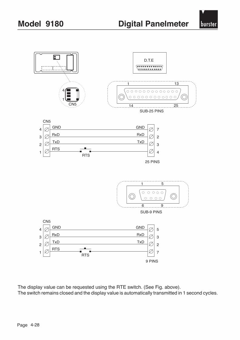
Model 9180 bursterDigital Panelmeter
Page 4-28
4
1CN5
D.T.E
1 13
14 25
SUB-25 PINS
1 5
6 9
SUB-9 PINS
CN5
4
3
2
1
7
2
3
4
GND
RxD
TxD
RTS
GND
RxD
TxD
RTS
CN5
4
3
2
1
5
3
2
7
GND
RxD
TxD
RTS
GND
RxD
TxD
RTS
25 PINS
9 PINS
The display value can be requested using the RTE switch. (See Fig. above).The switch remains closed and the display value is automatically transmitted in 1 second cycles.
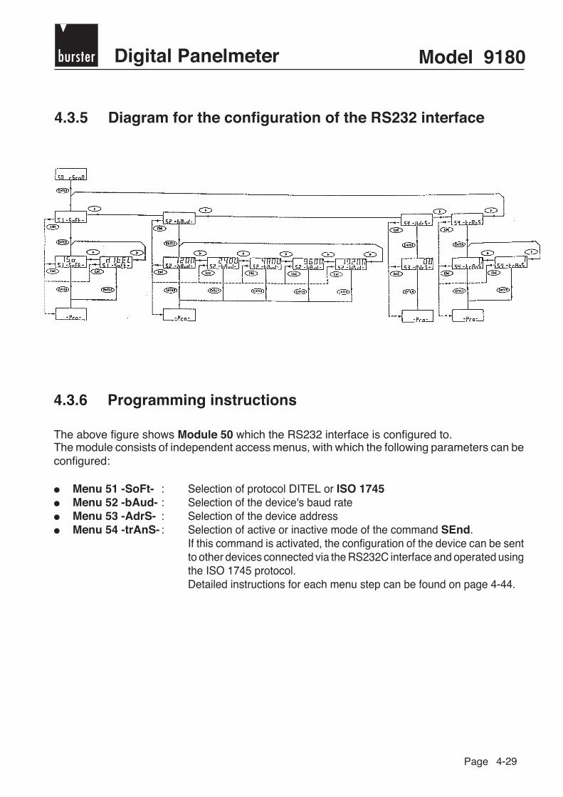
burster Digital Panelmeter Model 9180
Page 4-29
4.3.5 Diagram for the configuration of the RS232 interface
4.3.6 Programming instructions
The above figure shows Module 50 which the RS232 interface is configured to.The module consists of independent access menus, with which the following parameters can beconfigured:
Menu 51 -SoFt- : Selection of protocol DITEL or ISO 1745 Menu 52 -bAud- : Selection of the device's baud rate Menu 53 -AdrS- : Selection of the device address Menu 54 -trAnS- : Selection of active or inactive mode of the command SEnd.
If this command is activated, the configuration of the device can be sentto other devices connected via the RS232C interface and operated usingthe ISO 1745 protocol.Detailed instructions for each menu step can be found on page 4-44.

Model 9180 bursterDigital Panelmeter
Page 4-30
4.3.7 Access for programming the RS232 interface
Fig. 4.3.7
MAX
MIN
1
HOLD
TARA
2
TARE RESET
ESC
LIMIT MAX/MIN DATA
ENTER
3
4
4.3.8 Selection of the communications protocol
Fig. 4.3.8a
MAX
MIN
1
HOLD
TARA
2
TARE RESET
ESC
LIMIT MAX/MIN DATA
ENTER
3
4
Fig. 4.3.8b
MAX
MIN
1
HOLD
TARA
2
TARE RESET
ESC
LIMIT MAX/MIN DATA
ENTER
3
4
Press the "ENTER" key to go from theoperating mode to the programming mode(Display -Pro- in the secondary display)and keep pressing the " " key until youare in level 50 (see Fig. 4.3.7). Press the"ENTER" key to go to menu 51 orESC: to return to the input level
(-Pro-)
Press the " " key if you wish to switch theprotocol displayed and "ENTER" to confirmthis selection. You automatically return tothe -Pro- level.ESC: Returns you to the input level
(-Pro-).
At the beginning of the selection menu forinterface setting the display appears asshown in Fig. 4.3.8a.Press the "ENTER" key and the activeinterface protocol appears in the maindisplay (Fig. 4.3.8b).ESC: Returns you to the input level
(-Pro-)
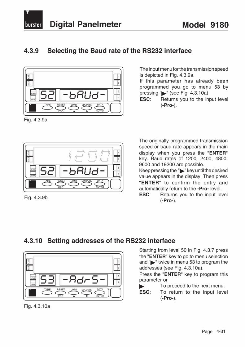
burster Digital Panelmeter Model 9180
Page
MAX
MIN
1
HOLD
TARA
2
TARE RESET
ESC
LIMIT MAX/MIN DATA
ENTER
3
4
4-31
4.3.9 Selecting the Baud rate of the RS232 interface
MAX
MIN
1
HOLD
TARA
2
TARE RESET
ESC
LIMIT MAX/MIN DATA
ENTER
3
4
Fig. 4.3.9b
MAX
MIN
1
HOLD
TARA
2
TARE RESET
ESC
LIMIT MAX/MIN DATA
ENTER
3
4
The originally programmed transmissionspeed or baud rate appears in the maindisplay when you press the "ENTER"key. Baud rates of 1200, 2400, 4800,9600 and 19200 are possible.Keep pressing the " " key until the desiredvalue appears in the display. Then press"ENTER" to confirm the entry andautomatically return to the -Pro- level.ESC: Returns you to the input level
(-Pro-).
4.3.10 Setting addresses of the RS232 interfaceStarting from level 50 in Fig. 4.3.7 pressthe "ENTER" key to go to menu selectionand " " twice in menu 53 to program theaddresses (see Fig. 4.3.10a).Press the "ENTER" key to program thisparameter or
: To proceed to the next menu.ESC: To return to the input level
(-Pro-).
Fig. 4.3.10a
Fig. 4.3.9a
The input menu for the transmission speedis depicted in Fig. 4.3.9a.If this parameter has already beenprogrammed you go to menu 53 bypressing " " (see Fig. 4.3.10a)ESC: Returns you to the input level
(-Pro-).

Model 9180 bursterDigital Panelmeter
Page
MAX
MIN
1
HOLD
TARA
2
TARE RESET
ESC
LIMIT MAX/MIN DATA
ENTER
3
4
MAX
MIN
1
HOLD
TARA
2
TARE RESET
ESC
LIMIT MAX/MIN DATA
ENTER
3
4
4-32
Fig. 4.3.10b
MAX
MIN
1
HOLD
TARA
2
TARE RESET
ESC
LIMIT MAX/MIN DATA
ENTER
3
4
The main display shows a two-digit numberwhich corresponds to the previously setaddress. The left digit of this number flashes.If you would like to program another address,press the " " key to change the value of theflashing digit or " " to go to the next digit.You select addresses between 00 and 99.Press the "ENTER" key to save the entryand return to the -Pro- level.
Fig. 4.3.11a
4.3.11 Transfer configuration
Fig. 4.3.11b
In the input level 50 (see Fig. 4.3.7) press the"ENTER" key and then press " " threetime to go to the level shown in Fig. 4.3.11a(54 -trAnS- in the auxiliary display).Using this menu the programming of a devicecan be copied to another device connectedto the RS232C.Press the "ENTER" key to access this menuor
: To proceed to the next menu.ESC: Returns you to the input level
(-Pro-).
A flashing number (0 or 1 depending onprevious selection) appears in the display."0" means that the option is not activatedand "1" means that the option can be used.The displayed value corresponds to thedesired option. Press the "ENTER" or "ESC"keys to return to the -Pro- level. If this is notthe case press the " " key to change thenumber as well as "ENTER" to save theentry and go to the -Pro- level.
burster Digital Panelmeter Model 9180
Page 4-33
SEnd command (transfer configuration)
To be able to use this command you must have previously selected option "1" in menu54 -trAnS- and the option "ISo" and -SoFt - in menu 51 (for the communications protocolISO 1745).
To copy the programming from one device to another, the 9180 receiver must have the sameaddress as the 9180 transmitter (see page 4-44).You are in menu 54 and have set the trAns-Parameter to "1". Confirm this by pressing "ENTER".You now find yourself again in the "Pro" level.Press the "TARE" button and the message SEnd appears in the secondary display.If you would now like to send the program parameters press the "ENTER" key or, if you wish tocancel the command, press "ESC". [1st level -Pro-, 2nd button "TARE", 3rd key "ENTER"].
4.4 RS485 (RS4) option
4.4.1 Introduction
The output option RS485 consists of an additional card (reference RS4), which is installed in theM1 connection slot of the device's base plate.The card has a Western-type telephone connection terminal with an output at the rear side of thedevice.
Using the RS485 you can set up a communications line by means of which a master unit canrequest data from one or more display instruments, like e.g. the display value, switching points,min. and max. values, tare values (or offset in the case of a thermometer). Furthermore externalfunctions can be performed like the deletion of the memory for min., max. and tare values andchanges to the switching points.
The model 9180 is also provided with a command you can use to copy the programming intoanother device of the same type.The option can be configured completely via software, i.e. baudrate (1200, 2400, 4800 or 9600),device addressing (programmable between 00 and 99), type of protocol (DITEL or Standard ISO1745) and time delay.
Using the RS485 option up to 31 devices can be connected to the main device with output RS485.The function mode is half-duplex. The channel is only active if the device, which is normally inreceiving mode until a message is obtained, is in operating mode.
Model 9180 bursterDigital Panelmeter
Page 4-34
If the device receives a valid message an action can be performed immediately
4.4.2 Protocol and commands
Two modes of communication have been provided for:The DITEL mode operates with a simple protocol. Using the ISO mode, corresponding to the ISO1745 standard, the communication can be performed effectively in a distorted or disturbedenvironment, as here the validity of a message has to be checked both during transmission aswell as reception.As in the function table shown on page 4-35, the DITEL protocol operates with 1 or 2 bytesdepending on the type of command, while the ISO 1745 protocol needs two bytes per command.
A example in BASIC in SOURCE CODE you can findat the end of this manual.
DITEL protocol
The word format 1START bit, 8 data bits and one StOP bit.
Sending messages to the deviceA message sent to the device must consist of a sequence of ASCII codes:
D d C C X ........................................X CR
Symbol "" [ASCII 42] signifies the beginning of the message. Two address digits (between 00 and 99). One or two ASCII codes for the desired command in accordance with the function table on page
4-35.If it involves a command for changing parameters, the new value is transmitted in the form of asymbol byte [ASCII 43] or -[ASCII 45], followed by a block made up of n-ASCII codes includingdecimal point.
Symbol "CR" [ASCII 13] signifies end of message.

burster Digital Panelmeter Model 9180
Page 4-35
Receiving messages from the deviceThe format of messages sent by the device as a response to a command for data requestis as follows:
SP X ........................................X CR
One byte for space [ASCII 32]. One text (desired value) consisting of a symbol byte [ASCII 43] or - ] ASCII 45]
followed by a block made up of n-ASCII codes including decimal point. Symbol "CR" [ASCII 13] signifying end of message.
Example:
If it involves instructions or commands for changing parameters the device does not respond.
Truth table
Command Function Function typeDITEL ISO
V 0V Transmission of the min. memory content
P 0P Transmission of the max. memory content
T 0T Transmission of the TARE memory content
(Offset in the case of thermometers)
D 0D Transmission of the display value
L1 L1 Transmission of the switching point value 1
L2 L2 Transmission of the switching point value 2
L3 L3 Transmission of the switching point value 3
L4 L4 Transmission of the switching point value 4
v 0v Delete the min. value memory
p 0p Delete the max. value memory
r 0r Delete the tare memory
t 0t Input display value as tare
M1 M1 Change switching point 1
M2 M2 Change switching point 2
M3 M3 Change switching point 3
M4 M4 Change switching point 4
Change in
the
Parameter
Instructions
Request
Data

Model 9180 bursterDigital Panelmeter
Page 4-36
Protocol ISO 1745
For the word format, 1 start bit, 7 data bits, 1 parity bit and 1 stop bit are needed.
Sending messages to the device
SOH D d STX C C X ............... X ETX BCC
One SOH byte for the beginning of the message [ASCII 01]. One byte for the tens digit and one byte for the ones digit of the device address to be targeted. One STX byte signifying text beginning [ASCII 02]. Two command bytes in accordance with the function table. For commands to change parameters one block of n-bytes for the numerical value including
decimal point. One ETX byte for end of text [ASCII 03]. One BCC control byte is computed as follows:
Performance of an Exclusive-OR for all bytes between STX (not included) and ETX(included)
- If the byte lies in ASCII code at ≥ 32 it can be used as BCC control byte.- If the byte lies in ASCII code at < 32 you obtain the BCC control byte by adding 32.
Example:
Protocol ISO 1745
Messages received by the deviceThe typical message format which a device supplies as a response to a command from amaster unit, appears as follows:
1. For commands requesting a value:
SOH D d STX X ............... X ETX BCC
One SOH byte for the beginning of a message [ASCII 01]. 2 address bytes ( D = tens digit, d = ones digit ). One STX byte for beginning the text [ASCII 02]. n-bytes corresponding to the desired value (including symbols and decimal point). One ETX byte signifying end of text [ASCII 03]. One control byte computed as above.
If the master unit transmits a message with the address 00, the command is interpreted by all thedevices in the network and you obtain a response.
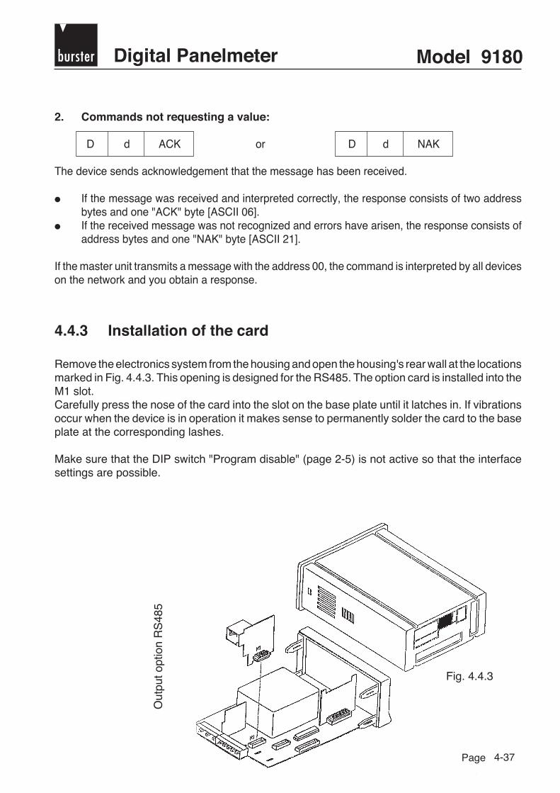
burster Digital Panelmeter Model 9180
Page 4-37
2. Commands not requesting a value:
D d ACK or D d NAK
The device sends acknowledgement that the message has been received.
If the message was received and interpreted correctly, the response consists of two addressbytes and one "ACK" byte [ASCII 06].
If the received message was not recognized and errors have arisen, the response consists ofaddress bytes and one "NAK" byte [ASCII 21].
If the master unit transmits a message with the address 00, the command is interpreted by all deviceson the network and you obtain a response.
4.4.3 Installation of the card
Remove the electronics system from the housing and open the housing's rear wall at the locationsmarked in Fig. 4.4.3. This opening is designed for the RS485. The option card is installed into theM1 slot.Carefully press the nose of the card into the slot on the base plate until it latches in. If vibrationsoccur when the device is in operation it makes sense to permanently solder the card to the baseplate at the corresponding lashes.
Make sure that the DIP switch "Program disable" (page 2-5) is not active so that the interfacesettings are possible.
Out
put o
ptio
n R
S48
5
Fig. 4.4.3

Model 9180 bursterDigital Panelmeter
Page 4-38
4.4.4 Terminals
Each output card is supplied with a sticker orlabel on which the connections for each optionare depicted (see Fig. 4.3.4a). For improveddevice identification this sticker should beattached to the rearside of the housing, rightnext to the sticker with the device's basicfunctions (see Fig. 4.3.4b).
4
CN 7
56
2 RL
NO 2CM 2NC 2
4 RL
RL 4N.C.COMM
40 P
OP 4N.C.COMM
1
CN 6
23
2 RL
NO 1CM 1NC 1
4 RL
RL 1RL 2RL 3
40 P
OP 1OP 2OP 3
1
CN 4 ANALOG OUTPUT
2(-)(+) 0-10 V/4-20 mA
CN 5GNDRXTXRTS
RS232CGNDABN/C
RS485
Fig. 4.4.4a: Sticker for options
Fig. 4.4.4b: Rearside of the device with connection for the RS4 option
CN5
1
6 GNDAB
NC
Fig. 4.4.4c: Fixing the sticker

burster Digital Panelmeter Model 9180
Page 4-39
4.4.5 Connection of several devices to the RS485 interface
Type 9180-1
D.T.E.
Type 9180-2 Type 9180-3
CN5
654321
-GND
AB
N/C-
CN5
654321
-GND
AB
N/C-
CN5
654321
-GND
AB
N/C-
Rt
Rt
1) Jumper J1 removed 1) Jumper J2 removed 2) Jumper J1 attached
With D.T.E., up to 31 display instruments can be connected to the same bus. Here each devicereceives its own address between 00 and 99.The address 00 applies for every connected device and can be used for commands by the masterunit to which the devices need not respond.A command which is sent to the address 00 is simultaneously executed by all devices(broadcast).
Jumper J1
Optionsplatine RS4
To connect different devices via the RS485 interface, a terminating resistor (Rt) with 120 Ω mustbe attached to both ends of the data line.The display instruments already contain this resistor Rt, which is connected internally to theoutputs 3 and 4 of the CN5 connection by means of the jumper J1 on the RS4 card. If severaldevices exist on the bus, J1 only remains connected to the last subscriber. The jumpers of all theother devices are to be removed.
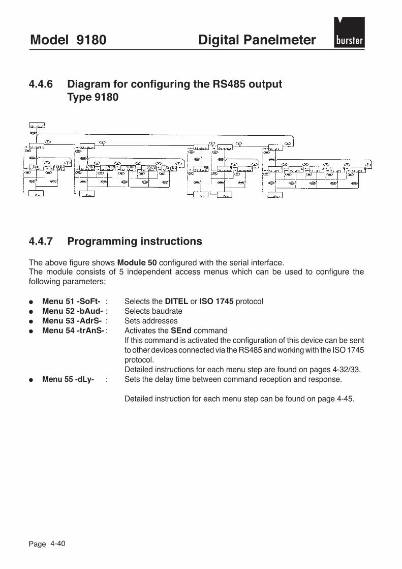
Model 9180 bursterDigital Panelmeter
Page 4-40
4.4.6 Diagram for configuring the RS485 outputType 9180
4.4.7 Programming instructions
The above figure shows Module 50 configured with the serial interface.The module consists of 5 independent access menus which can be used to configure thefollowing parameters:
Menu 51 -SoFt- : Selects the DITEL or ISO 1745 protocol Menu 52 -bAud- : Selects baudrate Menu 53 -AdrS- : Sets addresses Menu 54 -trAnS- : Activates the SEnd command
If this command is activated the configuration of this device can be sentto other devices connected via the RS485 and working with the ISO 1745protocol.Detailed instructions for each menu step are found on pages 4-32/33.
Menu 55 -dLy- : Sets the delay time between command reception and response.
Detailed instruction for each menu step can be found on page 4-45.

burster Digital Panelmeter Model 9180
Page
MAX
MIN
1
HOLD
TARA
2
TARE RESET
ESC
LIMIT MAX/MIN DATA
ENTER
3
4
burster
MAX
MIN
1
HOLD
TARA
2
TARE RESET
ESC
LIMIT MAX/MIN DATA
ENTER
3
4
4-41
4.4.8 Access to interface programming
Fig. 4.4.8
MAX
MIN
1
HOLD
TARA
2
TARE RESET
ESC
LIMIT MAX/MIN DATA
ENTER
3
4
burster
Press the "ENTER" key to go from theoperating mode to the programming mode(-Pro- appears in the secondary display)and keep pressing the " " key until youreach level 50 (see Fig. 4.4.8).Press the "ENTER" key to reach menu 51or
: To proceed to the nextprogramming module.
ESC: To return to the input level(-Pro-)
4.4.9 Communications protocol of the RS485 interface
Fig. 4.4.9a
Fig. 4.4.9b
The previously programmed protocol type[dItEL = Protokoll DITEL, ISO = ProtokollISO 1745] appears in the main display.Pages 4-34ff describe the way this protocoloperates.Press " " if you want to switch the optiondisplayed in the display and "ENTER" toconfirm the selection. You automaticallyreturn to the -Pro- level.ESC: Returns you to the input level
(-Pro-)
The selection menu for the interface protocolappears in level 51 (Fig. 4.4.9a).Press "ENTER" to activate this menu or
: To proceed to the next menu.ESC: To return to the input level
(-Pro-)

Model 9180 bursterDigital Panelmeter
Page 4-42
4.4.10 Selection of the baudrate of the RS485 interface
Fig. 4.4.10b
MAX
MIN
1
HOLD
TARA
2
TARE RESET
ESC
LIMIT MAX/MIN DATA
ENTER
3
4
Fig. 4.4.10a
MAX
MIN
1
HOLD
TARA
2
TARE RESET
ESC
LIMIT MAX/MIN DATA
ENTER
3
4
By pressing the "ENTER" key in theprevious routine the originally programmedbaudrate appears in the main display.Possible options are 1200, 2400, 4800,9600 and 19200 bauds.Keep pressing the " " key until the desiredvalue appears in the display. Then youpress "ENTER" to confirm your entry andautomatically return to the -Pro- level.ESC: Returns you to the input level
(-Pro-) without saving thechanges.
The display shown in Fig. 4.4.10a appearsas the selection menu for the baudrate.This menu is activated by pressing the"ENTER" key. If this parameter has alreadybeen programmed you reach the nextmenu using " ". (see Fig. 4.4.11a)ESC: Returns you to the input level
-Pro-.

burster Digital Panelmeter Model 9180
Page 4-43
4.4.11 Setting the addresses of the RS485 interface
Fig. 4.4.11b
MAX
MIN
1
HOLD
TARA
2
TARE RESET
ESC
LIMIT MAX/MIN DATA
ENTER
3
4
Fig. 4.4.11a
MAX
MIN
1
HOLD
TARA
2
TARE RESET
ESC
LIMIT MAX/MIN DATA
ENTER
3
4
The main display shows a two-digit addresswhich was programmed previously.The left digit of this address flashes.If you would like to program a differentaddress press the " " button to changethe value of the flashing digit and " " toselect the right digit. You can chooseaddresses between 00 and 99.Press "ENTER" to save the entry andautomatically return to the -Pro- level.
Starting with level 50 (Fig. 4.4.8) press"ENTER" to access menu selection and" " twice to reach menu 53 for addressprogramming (see Fig. 4.4.11a). Pressthe "ENTER" key to input the address or
: To proceed with menu 54ESC: To return to the input level -Pro-

Model 9180 bursterDigital Panelmeter
Page
MAX
MIN
1
HOLD
TARA
2
TARE RESET
ESC
LIMIT MAX/MIN DATA
ENTER
3
4
MAX
MIN
1
HOLD
TARA
2
TARE RESET
ESC
LIMIT MAX/MIN DATA
ENTER
3
4
4-44
4.4.12 Transfer configuration
Fig. 4.4.12a
In the input level to module 50 (Fig. 4.4.8)you press the "ENTER" key to reachprogramming mode and " " three timesto reach the level depicted in Fig. 4.4.12a)(54 -trAnS in the auxiliary display).This allows you to copy a device settinginto a different device via the serialinterface.Press "ENTER" to select this menu or
: To proceed to menü 54ESC: Returns you to the input level
-Pro-.
Fig. 4.4.12b
A flashing number appears in the display(0 or 1)."0" means that the option is not activatedand "1" means that the option can beused.If the value displayed (0 or 1) correspondsto the desired option press "ENTER" orESC: To return to the input level
-Pro-. If this is not the case press: To change the number and then
"ENTER" to save the entry andgo to the the -Pro- level.
SEnd command (transfer configuration)To be able to use this command, you must have previously selected the option "1" in menu54 -trAnS- and the option "ISo" in menu 51 -SoFt- (for the ISO 1745 communicationsprotocol).
To copy the programming from one device to the other, the 9180 on the receiving side must havethe same address as the transmitting 9180 (see pages 4-32/33).You are in menu 54 and you have set the trAns-Parameter to "1". Confirm this by pressing"ENTER". You will now find yourself back in the "Pro" level.Press the "TARE" key and SEnd appears in the secondary display.If you now wish to transfer the program parameters, press "ENTER" or if you wish to cancel thecommand, press "ESC". [1st level -Pro-, 2nd level - the "TARE" key, 3rd press "ENTER"].

burster Digital Panelmeter Model 9180
Page
MAX
MIN
1
HOLD
TARA
2
TARE RESET
ESC
LIMIT MAX/MIN DATA
ENTER
3
4
MAX
MIN
1
HOLD
TARA
2
TARE RESET
ESC
LIMIT MAX/MIN DATA
ENTER
3
4
4-45
4.4.13 Set the time delay for the RS485 interface
At the start of module 50 (Fig. 4.4.8) press"ENTER" to access the programmingmenu and then the " " button four timesto set the device into the input level ofmenu 55 dLY (Fig. 4.4.13a).In this menu a time delay can be set for thedevice response to a command. The aimof this delay is to avoid information loss, ifthe response reaches the master unitbefore it is ready to receive. This can arisein half-duplex interfaces because hereinformation is transmitted and receivedover the same line. Press "ENTER" to goto the next menu or
: To abandon this menu and returnto menu 51
ESC: To return to the input level -Pro-
Fig. 4.4.13b
By pressing the "ENTER" key in theprevious step a flashing number between1 and 5 appears in the display (dependingon the programming)1 = time delay of 30 ms, 2 = time delay of 60 ms, 3 = time delay of 100 ms, 4 = time delay of 300 ms 5 = without time delay.Keep pressing the " " button until thedesired time delay value is displayed and"ENTER" to save this value andautomatically return to the operating mode.
Fig. 4.4.13a

Model 9180 bursterDigital Panelmeter
Page 4-46
4.5 BCD output option
4.5.1 Introduction
The BCD output option supplies 5 1/2 digits in BCD code.Using the TRISTATE, the output remains highly resistive so that various display instruments canuse the same communications bus.
All of the outputs are compatible with TTL or 24 V logic and are optically isolated with respect tothe input signal to the extent that the card is supplied to an external voltage between 5 V and24 V.
As long as the TRISTATE input is set to "low", the data output is updated in the same cycle asthe data appears in the display. If the TRISTATE input is set to "high", the impedance of all theoutputs including DATA VALID is increased so that the same bus can also be used for otherapplications.The DATA VALID signal is updated when the data are available in the communication bus.
When the display is on HOLD the data output is also stopped.
The output signals can operate with positive or negative logic. The selection of the logic type isperformed by interchanging the ICs of the option card as well as resetting two connectablejumpers. Programming using the keyboard is not necessary.

burster Digital Panelmeter Model 9180
Page 4-47
4.5.2 Installation of the card
Remove the electronics from the housing and open the location marked in Fig. 4.5.2. This openingis designed for the BCD output option.
The BCD card is connected to the J6 socket on the base plate of the device via a flatband cable(see Figure 2).
This is easier when you take out the card.
If the card is connected to the device, it is inserted horizontally into the base plate. It is designedso that it slides and latches into the base plate.Guiderails which hold the card are located in the housing.
Fig. 4.5.2
Fig. 4.5.2a

Model 9180 bursterDigital Panelmeter
Page 4-48
The card is inserted into the slot in the front panel (Fig. 4.5.2b) and lies in the opening of the inputcard.
The flat cable is bent and lies on the transformer (Fig. 4.5.2b).
Then the electronic unit with the BCD card (Fig. 4.5.2b) is inserted back into the housing. Sincethis option must not be configured by the software, the device is now ready for operation.
Fig. 4.5.2b

burster Digital Panelmeter Model 9180
Page 4-49
4.5.3 Terminals of the BCD output
The BCD output card is supplied with a sticker on which the terminals are depicted.
DATA VALID
21842010
40 80100 200400 8001 K 2 K4 K 8 K
10 K 20 K40 K 80 K
100 K POLARITYOVERRANGE
TRIESTATE N.C.N.C. GNDN.C. N.C.
+24 V/TTL +24 V/TTLN.C.N.C.
1 23 45 67 89 10
11 1213 1415 1617 1819 2021 2223 2425 2627 2829 3031 3233 34
Designation of the pins
DA
TA V
.
1
2
33
34
21
84
2010 40
8010
020
040
080
01
K2
K4
K8
K10
K20
K40
K80
K10
0 K
PO
LO
VE
RT
R 1
N.C
.N
.C.
GN
DN
.C.
N.C
.+
24 V
+24
VN
.C.
N.C
.
CN8
BCD OUT
BCD option sticker
In order for the outputs to be optically isolated with respect to the input signal, the card must besupplied with an external voltage between 5 V and 24 V at pins 31/32 (+) and 28 (-).
CN8
1
2
3334
Rearside of the BCDoption

Model 9180 bursterDigital Panelmeter
Page 4-50
An adapter with a 37-pin SUB-D connector is supplied together with the BCD card.The adapter also consists of a 34-pin connector which is plugged into the output terminal of theBCD card.
The 37-pin connector has the pin assignment:
1 = 1 20 = 22 = 4 21 = 83 = 10 22 = 204 = 40 23 = 805 = 100 24 = 2006 = 400 25 = 8007 = 1K 26 = 2K8 = 4K 27 = 8K9 = 10K 28 = 20K10 = 40K 29 = 80K11 = 100K 30 = Polarity12 = Excess 31 = Data Valid13 = Tristate 32 = N.C.14 = N.C. 33 = GND15 = N.C. 43 = N.C.16 = +24V/TTL 35 = +24/TTL17 = N.C. 36 = N.C.18 = N.C. 37 = N.C.19 = N.C.
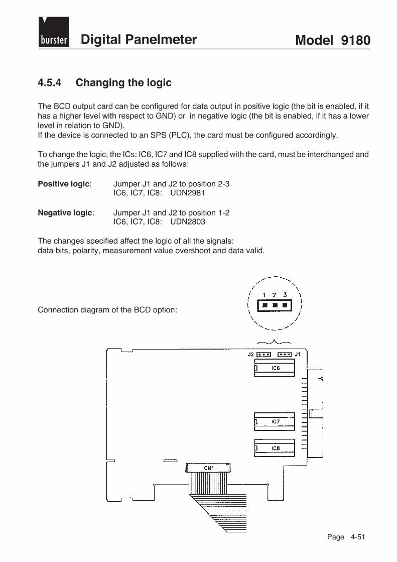
burster Digital Panelmeter Model 9180
Page 4-51
4.5.4 Changing the logic
The BCD output card can be configured for data output in positive logic (the bit is enabled, if ithas a higher level with respect to GND) or in negative logic (the bit is enabled, if it has a lowerlevel in relation to GND).If the device is connected to an SPS (PLC), the card must be configured accordingly.
To change the logic, the ICs: IC6, IC7 and IC8 supplied with the card, must be interchanged andthe jumpers J1 and J2 adjusted as follows:
Positive logic: Jumper J1 and J2 to position 2-3IC6, IC7, IC8: UDN2981
Negative logic: Jumper J1 and J2 to position 1-2IC6, IC7, IC8: UDN2803
The changes specified affect the logic of all the signals:data bits, polarity, measurement value overshoot and data valid.
Connection diagram of the BCD option:

Model 9180 bursterDigital Panelmeter
Page 4-52
The following schemes depict one of the BCD outputs in positive and negative logic respectively.
Positive logic
Negative logic
The TRISTATE input is triggered externally and is always active at level "1".
In positive logic the signals are active atlevel "1" and negative at level "0".The POLARITY is positive (+), if the bit is ona high level and negative (-), if it is on a lowlevel with respect to GND.The MEASUREMENT VALUE OVER-SHOOT is positive, if the bit is on a high leveland negative, if it is on a low level. Whenthere is measurement value overshoot, thefour lowest digits (D0, D1, D2 und D3) areFFFF.
Parameters of the output transistors: Vmax = 40 V Imax = 100 mA
Pin assignment corresponds to pages 4-49/50

burster Digital Panelmeter Model 9180
Page 5-1
5. Pin assignment of the table-top version
Assignment for through-chassis terminalAnalog output Digital In: Digital Out:0 ... 10 V or Control Option 2RE 4RE 4OP 4OPP4 ... 20 mA 3: Reset 8: NO1 RL1 OP1 OP11: +Output 4: Hold 9: COM1 RL2 OP2 OP22: -Output 5: Ground 10: NC1 RL3 OP3 OP3
6: Tara 11: NO2 RL4 OP4 OP47: Max/Min 12: COM2 N/C N/C N/C
13: NC2 COM COM COM
see also page 4-15
5.1 Position and meaning of the connection sockets
Assignment of the 12 pin flange socket(DMS)A/B: -feedC/D: +feedE: Function ground (= Pin A,B)F: -Meas. signal DMSG: +Meas. signal DMSJ: Shielding (PE)
Shu
nt
= - Feed
= - Meas. signal
Assignment of the 12 pin flange socket(Poti, Process)A/B: -feedC/D: +feedE: Function ground (= Pin A,B)F: -Meas. signal V, mA, Pt 100G: +Meas. signal V, PotiJ: Shielding (PE)L: +Meas. signal mA
Assignment of the 9-pin Sub-Min-D-Socket Assignment of the 9-pin Sub-Min-D-ConnectorSerial interface RS232/485 Serial interface RS2325: Protective, GND 5: Protective, GND2: TxD, B (RS485) 1: A3: RxD 2: B7: RTS1: A (RS485)
Service socket forshunt calibration

Model 9180 bursterDigital Panelmeter
Page 5-2
5.2 Strain gage sensor (DMS) connection
C +Feed
G +Signal
F -Signal
A -Feed
PE
DMS
DMS (Load)
GH
F E
D
CB
L
AK
J
M
C +Feed
G +Signal
F -Signal
A -Feed
PE
Poti
Poti (Process)
GH
F E
D
CB
L
AK
J
M
5.3 Potentiometer connection

burster Digital Panelmeter Model 9180
Page 5-3
5.4 Connection of process signals up to 300 mV
5.5 Connection of process signals up to 10 V
5.6 Connection of process signals up to 20 mA
G
F
to ±10 V
Poti (Process)
GH
F E
D
CB
L
AK
J
M
L
F
0 ... 20 mA
Poti (Process)
GH
F E
D
CB
L
AK
J
M
G
F
to ±300 mV
DMS (Load)
GH
F E
D
CB
L
AK
J
M

Model 9180 bursterDigital Panelmeter
Page 5-4
5.7 Connection of transmitter to current output
C +Feed
L +Signal
PE
Transmitter0...1 mA/
0(4)...20 mA F -Signal
A -Feed
4 wire
L -Signal
PE
Transmitter4...20 mA
C +Signal
2 wire
Poti (Process)
GH
F E
D
CB
L
AK
J
M
Poti (Process)
GH
F E
D
CB
L
AK
J
M
5.9 Connection of Pt 100
5.8 Connection of transmitter to voltage output
C +Feed
G +Signal
PE
Transmitter±1V/±10V
F -Signal
A -Feed
Poti (Process)
GH
F E
D
CB
L
AK
J
M
C +Feed
G GND
2 wire
F -Signal
DMS (Load)
GH
F ED
CB
L
AKJ
M

burster Digital Panelmeter Model 9180
Page 5-5
5.10 Technical data
5.10.1 Electrical specifications
Process signal U IMax. input ± 10 V DC ± 20 mA DCResolution 1 mV 1 µAInput resistance 1 MΩ 15 ΩFeed 24 V (30 mA) 10 V (120 mA), 5 V (120 mA)
Strain gage (DMS): Max. voltage ± 300 mV DCMax. resolution 0.75 µVInput resistance 100 MΩFeed 10 V (120 mA), 5 V (120 mA)
Potentiometer: Max. voltage ± 10 V DCDisplay resolution 0.001 %Input resistance 1 MΩFeed 10 V (120 mA)
Temperature: Input compensation ± 0 °C + 50 °CFeed current Pt 100 < 1mA DCMax. cable resistance 40 Ω
Pt 100 - 100 °C to 800 °C 0.1 °C ± 0.2 % v.M. ± 0,6 °C (Ι ≤ 1 mA DC) 1.0 °C ± 0.2 % v.M. ± 1.0 °C
Thermocouple - 50 °C to 800 °C 0.1 °C ± 0.4 % v.M. ± 0.6 °Ctype J 1.0 °C ± 0.4 % v.M. ± 1.0 °C
Thermocouple - 30 °C to 1200 °C 0.1 °C ± 0.4 % v.M. ± 0.6 °Ctype K 1.0 °C ± 0.4 % v.M. ± 1.0 °C
Thermocouple - 200 °C to 400 °C 0.1 °C ± 0.4 % v.M. ± 1.0 °Ctype T 1.0 °C ± 0.4 % v.M. ± 2.0 °C
Thermocouple ± 0 °C to 1700 °C 0.1 °C ± 0.5 % v.M. ± 2.0 °Ctype R 1.0 °C ± 0.5 % v.M. ± 4.0 °C
Thermocouple ± 0 °C to 1700 °C 0.1 °C ± 0.5 % v.M. ± 2.0 °Ctype S 1.0 °C ± 0.5 % v.M. ± 4.0 °C
Thermocouple - 50 °C to 850 °C 0.1 °C ± 0.4 % v.M. ± 1.0 °Ctype E 1.0 °C ± 0.4 % v.M. ± 2.0 °C
Input type Temperature range Resolution Accuracy

Model 9180 bursterDigital Panelmeter
Page 5-6
Accuracy: Maximum error 0.1 % ± 3 digitTemperature coefficient 50 ppm/°CWarm-up time 10 minutes
Response time: without digital filter 175 ms ± 25 ms
With digital filter with filter LO 275 ms ± 25 mswith filter Md 425 ms ± 25 mswith filter HI 775 ms ± 25 ms
Converter: Technique double rampResolution (± 15 bit)Clock pulse 16/s (8 s temperature)
Display: Main display - 99999/ + 99999,6 red digits 14 mm
Aux. display 2 + 6 green digits 8 mmProgrammable meas. range from - 99999 to + 99999Decimal point programmableLEDs 8 FunctionsDisplay speed HI = 125 ms, LO = 0.5 s
Error message: OVFLO Nominal range exceeded
Power supply: AC voltage 230/115 V, 24/18 V(-15/+10%)50/60 Hz
Power 5 W (without options),10 W (max.)
Ambient temp.: Operating temperature 0 °C up to + 50 °CStorage temperature - 25 °C up to + 85 °CRelative humidity < 95 % (40 °C)
Dimensions: Dimensions 96 x 48 x 120 [mm]Weight 600 gHousing material plastic s/UL 94 V-0

burster Digital Panelmeter Model 9180
Page 5-7
5.10.2 Dimensions [mm] and assembly
Assembly:
1. Break out an area of 92 x 45 mm from the switching cabinet wall and insert the instrument.
2. Place the rubber seal between the front panel and the switching cabinet wall and press thefastening clips to the housing from behind until they latch on.
3. Proceed in reverse to disassemble.

Model 9180 bursterDigital Panelmeter
Page

burster Digital Panelmeter Model 9180
Page 6-1
A P P E N D I X
ExampleBASIC

Model 9180 bursterDigital Panelmeter
Page 1

burster Digital Panelmeter Model 9180
Page 2

Model 9180 bursterDigital Panelmeter
Page 3

burster Digital Panelmeter Model 9180
Page 4