bus bar and instrumentation
TRANSCRIPT

Bus Bar and Instrumentation
Rodger Bossert
Fermi National Accelerator Laboratory
HL-LHC AUP Pre-series Production Readiness Review– Sept 16, 2020

Outline
Scope, FRS, Acceptance Criteria
Organization
Final Design Specifications – models and drawings
Interfaces
Design Analysis
Design Validation Tests
Fabrication plan – Traveler
ES&H
QA/QC
Summary
HL-LHC Preseries PRR September 16, 2020 2

Q1/Q3 Busbar, Exp Loop and Instrumentation Scope
Requirements can be found in the Requirements specification document US-HiLumi-docdb-64,
Sections 11.1 and 11.2. Summaries are listed below:
• R-T-11: The LMQXFA cold mass will have two main superconducting leads on each side going through the busbar line connection. An
additional pair of resistive leads (trim) are required to have current unbalance up to 35 A between the two magnets during operation. The
additional leads exit the cold mass through the helium vessel connection. Four additional resistive leads (CLIQ, two per magnet) are
required for protection system.
• R-T-12: The 18 kA busbars will be made with the same Nb-Ti cable used for the connections of the magnet.
• R-T-13: The busbars must include expansion loops, to be contained within the end cover section and able to accommodate up to 30 mm
of axial movement due to differential thermal expansion/contraction. The maximum force allowed for a 30 mm displacement is 500 N.
• R-O-03: The busbars will include maximum four internal splices. Each splice resistance target value must be less than 1.0 nΩ at 1.9 K.
A target value at room temperature will also be specified after the completion of the prototype program. An acceptance threshold will be
defined after the completion of the short model program. There are CERN requirements for the splice resistance as well as the
solder and flux used for these splices:
• R-T-14: Splices are to be soldered with CERN approved materials.
11.1 Busbars Scheme and Requirements
• R-T-16: In each cold mass, two temperature sensors will be installed. These sensors are the short type thermometer assembly (36
mm x 12 mm x 10 mm) typically used by CERN and specified in [10]. The location is chosen to minimize the radiation dose and to
give the most reliable information for both magnets. Two sensors in the same positions are used for redundancy. The thermometer
assemblies will be calibrated and supplied by CERN.
• R-T-17: The LMQXFA cold mass assembly includes a minimum of 16 voltage taps. The Quench Detection voltage taps should follow
MQXFA redundancy requirement (see [1] R-T-15).
• R-T-18: Instrumentation wires type, preliminary quantity and function are given in Table 2 of the FDR.
• R-T-19: The LMQXFA instrumentation wiring must exit the cold mass assembly through the helium vessel connection.
Instrumentation of each magnet will exit the cold mass on opposite sides.
11.2 Electrical/ Instrumentation Requirements
3HL-LHC Preseries PRR September 16, 2020

Q1/Q3 Bus Bar, Exp Loop and Instrumentation Scope
List of items in scope of Bus, Expansion loops and Instrumentation:
• Bus assembly with housing
• Upper and Lower Expansion loops
• Lead and expansion loop hold-down parts
• Splices from “A” lead to local bus
• Kmod (Trim Leads)
• CLIQ lead routing
• Instrumentationo Cryo Heaters (Warmup Heaters)
o Temperature Sensors
o MTF temperature sensors
o Quench Detection Voltage Taps
o Coil Voltage Tap Routing
o Coil Protection Heater wire routing
4HL-LHC Preseries PRR September 16, 2020

Bus and Expansion loop Final Design Specifications
The bus and expansion loop system for the entire triplet is shown in the illustration below. A
Q1/Q3 is shown in the lower illustration (area in dotted rectangle). This system is
consistent with the CERN electrical schematic LHCLMQXF E000.
5HL-LHC Preseries PRR September 16, 2020

Q1/Q3 Bus and Expansion loop Final Design Specifications Cold Mass sub-assembly drawing F10138329 (shown below) includes the bus, expansion
loop and instrumentation. Exceptions are the warm-up heaters and the MTF temperature
sensor, which are included on the cold mass shell closure assembly, drawing F10138327
6HL-LHC Preseries PRR September 16, 2020

Q1/Q3 Bus and Expansion loop Final Design Specifications Cold Mass shell closure assembly, drawing F10138327, which includes the warmup heaters
and MTF temperature sensors.
7HL-LHC Preseries PRR September 16, 2020

Bus and Expansion loop Final Design Specifications
Q1/Q3 and Q2 Bus Assembly The through bus is similar to the design used for the MQXB (LHC IR triplet) magnets in the current IR
triplet. It consists of two pairs of special rectangular NbTi cable used for busses and coil leads as
(CERN drawing number LHCMQXFB0079), consistent with requirement R-T-12. Each pair is soldered
together and wrapped with Kapton. The pair will be wrapped together as shown and placed into a bus
housing made of G-11 The assembly drawing of the bus is FNAL #F10119849.
The amount of kapton between each bus is 995 um. 50 um (2 mil) kapton will withstand 6100V/mil.
125 um (5 mil) kapton will withstand 3900 V/mil. The bus insulation can therefore withstand a total
electrical resistance of 131kV, which far exceeds the High Voltage withstand requirement of 4600 V (at
room temperature).
8
1 layer of 50 µm
Kapton with 66%
overlap = 150 µm
HL-LHC Preseries PRR September 16, 2020

Bus and Expansion loop Final Design Specifications
Q1/Q3 and Q2 Bus Manufacturing Solder used for the busses as well as the splices
consists of flat strips of 96% tin/4% silver, the
materials approved by CERN (R-T-14). Two pieces
of solder strip are placed between the cables and
enclosed in a full-length fixture (dwg F10119961),
then heated to 240 degrees C for approximately 10
minutes. The flux used is Solder Gel MOB 39
(specified by CERN). The solder joint for the busses
and splices were tested in a short model.
Busses are wrapped with layers of 50
µm thick Kapton. Wrapping is done on a
device designed at Fermilab for this
purpose (FNAL assembly drawing
#F10095440).
9HL-LHC Preseries PRR September 16, 2020

Bus and Expansion loop Final Design Specifications
Q1/Q3 and Q2 Bus Housing The bus is enclosed by a full-length G-11 bus housing drawing F10129998 (Q1/Q3 shown) and placed
within the designated bus port. The housing is supported by aluminum clips at fixed positions within the
bus port. The housing assembly is designed to withstand the magnetic forces on the bus and still stay
within the minimum flow requirements for the LMQXF cold mass. Two Q1/Q3 busses have been
manufactured and two Q2 busses with housings are ready to ship to CERN.
10HL-LHC Preseries PRR September 16, 2020
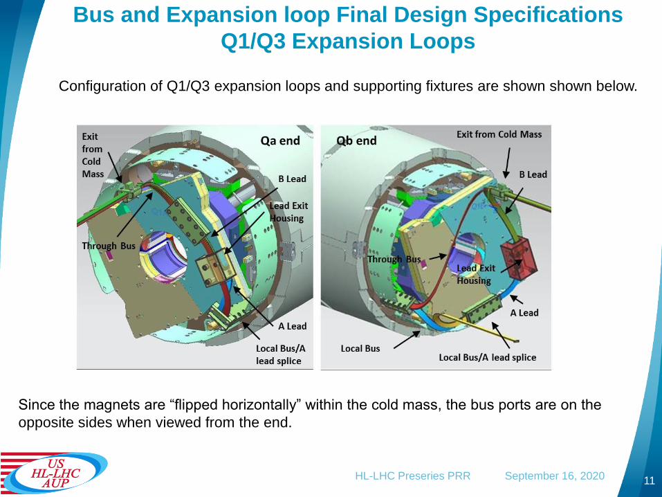
Bus and Expansion loop Final Design Specifications
Q1/Q3 Expansion Loops
Configuration of Q1/Q3 expansion loops and supporting fixtures are shown shown below.
Since the magnets are “flipped horizontally” within the cold mass, the bus ports are on the
opposite sides when viewed from the end.
11HL-LHC Preseries PRR September 16, 2020

Bus and Expansion loop Final Design Specifications
Q1/Q3 Expansion Loop Travel The space between the splice box and the inside surface of the end cover is 75mm +/-
1mm. To allow for thermal expansion, the upper expansion loops need to have +/- 18mm
of travel while the lower loops need +/-7mm. Expansion loop calculations are given in US-
HiLumi-doc-3208. Loops were tested on a full-scale mockup and meet the requirements.
The “home” or room temperature position of the loops is in the approximate center of
the space allowed, as shown in the figure above.
12HL-LHC Preseries PRR September 16, 2020

Bus and Expansion loop Final Design Specifications
CLIQ and Kmod (Trim) Leads
Two CLIQ leads exit the splice box on each end of the magnet, and exit through the
CLIQ/Kmod capillary (designed and supplied by CERN). Kmod (trim) leads are soldered to
the magnet leads and exit on only the Qa end through the CLIQ/Kmod capillary. They are
35A copper cables (not superconducting) with a 10mm2 cross section.
Cable used for the CLIQ and Kmod leads is identical and is supplied by CERN. The cable
specification is available at US-Hilumi-doc-998.
13HL-LHC Preseries PRR September 16, 2020

Bus and Expansion loop Final Design Specifications
MTF Lead
One special lead is added to allow either the Qa or the Qb to be tested separately on the
horizontal stand at the Fermilab Magnet Test Facility.
The MTF lead is soldered to the A lead and local bus and will not be used after testing. It
will be cut and capped before the Cryo-assembly is shipped to CERN,
14HL-LHC Preseries PRR September 16, 2020
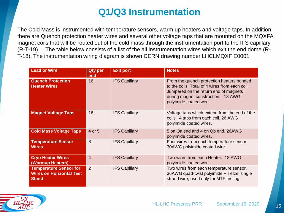
Q1/Q3 Instrumentation
The Cold Mass is instrumented with temperature sensors, warm up heaters and voltage taps. In addition
there are Quench protection heater wires and several other voltage taps that are mounted on the MQXFA
magnet coils that will be routed out of the cold mass through the instrumentation port to the IFS capillary
(R-T-19). The table below consists of a list of the all instrumentation wires which exit the end dome (R-
T-18). The instrumentation wiring diagram is shown CERN drawing number LHCLMQXF E0001
Lead or Wire Qty per
end
Exit port Notes
Quench Protection
Heater Wires
16 IFS Capillary From the quench protection heaters bonded
to the coils Total of 4 wires from each coil.
Jumpered on the return end of magnets
during magnet construction. 18 AWG
polyimide coated wire.
Magnet Voltage Taps 16 IFS Capillary Voltage taps which extend from the end of the
coils. 4 taps from each coil. 26 AWG
polyimide coated wires.
Cold Mass Voltage Taps 4 or 5 IFS Capillary 5 on Qa end and 4 on Qb end. 26AWG
polyimide coated wires.
Temperature Sensor
Wires
8 IFS Capillary Four wires from each temperature sensor.
30AWG polyimide coated wire.
Cryo Heater Wires
(Warmup Heaters)
4 IFS Capillary Two wires from each Heater. 18 AWG
polyimide coated wire.
Temperature Sensor for
Wires on Horizontal Test
Stand
2 IFS Capillary Two wires from each temperature sensor.
36AWG quad-twist polyimide + Tefzel single
strand wire, used only for MTF testing.
15HL-LHC Preseries PRR September 16, 2020

Q1/Q3 Instrumentation Wire Exit
Wires from various sensors are shown as they exit the cold mass
Protection heater and coil voltage taps Quench Protection Voltage taps
Warmup Heater and Temperature
sensor Wires
16
MTF Temperature Sensor Wires
HL-LHC Preseries PRR September 16, 2020

Final Design Specs – Models & Fab Drawings
The complete
drawing tree structure
for the cold mass is
located at US-HiLumi-
doc-3094.
A subsection of the
Bus, Exp. loop and
Inst. section is shown
to the right.
17
Major subassemblies
are in brown.
Drawings that are
part of the Bus and
Inst section are in
blue. The structure of
the drawing tree
follows the Cold Mass
manufacturing steps.
HL-LHC Preseries PRR September 16, 2020

Bus and Instrumentation Interfaces.
18
Relevant Interfaces to the Q1/Q3 Bus, Exp Loop and Instrumentation System design:
• Quantity of NbTi bus cable needed for Q1/Q3 (with CERN through Miao Yu) – p8.
• Leads for local and through busses need to be of sufficient length to reach the splices of
the next element in line at CERN and able to be accommodated by the vertical test facility
at BNL. (with CERN and Fermilab/BNL coil manufacturing groups) – p.11.
• CLIQ lead, PH wire and coil voltage tap wire connection with magnets (with LBNL) –
p.16.
• Connection of lead exit housings to splice boxes (with LBNL) – p.11.
• Magnet physical length and space for Expansion Loop (with LBNL and CERN) – p.12.
• Thermometer, warmup heaters and associated wires (supplied by CERN) – p.15-16.
• Wire number identification for instrumentation wiring from BNL and LBNL for magnet and
from CERN for interface with IFS and CLIQ/Kmod capillaries – 15-16.
• Instrumentation system must be consistent with CERN schematic – p.5.
• Pipe connection to IFS and CLIQ/Kmod capillaries and thermal sensor installation, with
Cryostat group at Fermilab – p.13.
• Position and length of “MTF Lead” with horizontal test facility at Fermilab - p.14.
HL-LHC Preseries PRR September 16, 2020

Design Analysis
Structural, magnetic, and physical analysis has been done on the
bus and interconnect system. A list of the documents:
19
• Bus Soldering Fixture Temperature and Testing – US-HiLumi-doc-3256
• Expansion Loop Thermal Contraction Calculations. – US-HiLumi- doc-
3208
• Q1 Q3 Flow area – US-HiLumi-doc-3214
• Q1 Q3 Bus housing structural and magnetic analysis – US-HiLumi -
doc-3211
• Bus solder fill tests – US-HiLumi-doc-3286
• Q1 Q3 Mockup Report – US-HiLumi-doc-3289
• Bus Strand Temperature Tests – US-Hilumi doc – 3685
• Magnetic Analysis of forces on expansion loops – US-Hilumi doc 3689
HL-LHC Preseries PRR September 16, 2020
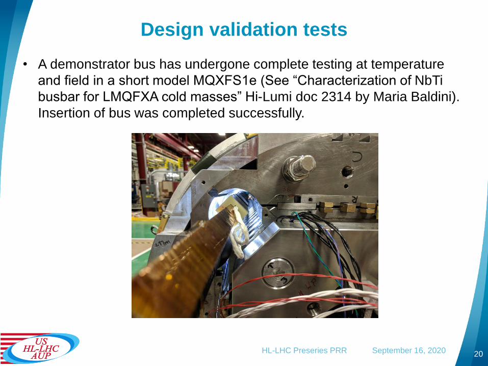
Design validation tests
• A demonstrator bus has undergone complete testing at temperature
and field in a short model MQXFS1e (See “Characterization of NbTi
busbar for LMQFXA cold masses” Hi-Lumi doc 2314 by Maria Baldini).
Insertion of bus was completed successfully.
20HL-LHC Preseries PRR September 16, 2020

Design validation tests
Full scale mockups were
completed for both the Q1/Q3
and Q2. Expansion loops
were modeled, and all bus
hold down fixtures were
installed. Travel of loops,
splice configuration, space for
all components and wire
routing were verified. (see
US-HiLumi-doc-3289).
21HL-LHC Preseries PRR September 16, 2020
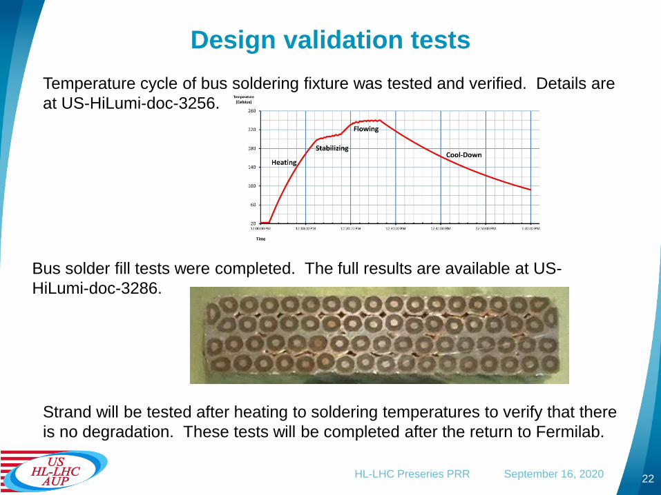
Design validation tests
Temperature cycle of bus soldering fixture was tested and verified. Details are
at US-HiLumi-doc-3256.
22
Bus solder fill tests were completed. The full results are available at US-
HiLumi-doc-3286.
Strand will be tested after heating to soldering temperatures to verify that there
is no degradation. These tests will be completed after the return to Fermilab.
HL-LHC Preseries PRR September 16, 2020

Design validation tests
23
Magnetic analysis was performed to understand forces on the expansion loops.
The full results are available at US-HiLumi-doc-3286.
HL-LHC Preseries PRR September 16, 2020

Fabrication plan – Traveler
24
Three travelers are relevant to the Q1/Q3 Bus and Instrumentation –
• 464574 HL-LHC AUP MQXFA Incoming Inspection and QA Traveler
• 464507 HL-LHC Magnet Bus Traveler
• 464525 HL-LHC AUP Q1 Q3 Cold Mass Assembly Traveler
A brief summary of the assembly steps:
• Incoming electrical inspection of all instrumentation on both magnets.
• After coils are aligned, insert previously fabricated bus/housing assembly.
• Install bus housing lock.
• Make local bus-to-A-lead splices and install splice housings.
• Install lead exit support fixtures.
• Form expansion loops on both Qa and Qb ends.
• Install all expansion loop hold-down fixtures
• Solder Kmod leads in the appropriate places.
• Route CLIQ and Kmod leads.
• Add quench detection voltage taps.
• Verify expansion loop travel on both ends.
• Install thermometers and route coil voltage taps and protection heater wires.
• After horizontal shell weld, install warm-up heaters and temperature sensors for horizontal test.
• Final physical and electrical inspections.
Note: electrical inspections are done
during assembly when appropriate, as
designated in traveler.
HL-LHC Preseries PRR September 16, 2020

ES&H
25
• ES&H coordinator is Amy Pavnica
• Operational hazards during Bus and Instrumentation Assembly include
Mechanical and Electrical hazards.
• The risk categories of identified hazards are summarized in US-HiLumi-
doc-1121
• Main Hazards
• Use of overhead crane and lifting fixtures
• High voltage tests
• Work with soldering – elevated temperatures.
• Pinch points for cable wrapper
• Documents:
• AUP Hazard Analysis Report (HAR)
• Document with CERN completed: Agreement on Compliance with the CERN
Safety Regulation for Mechanics (SR-M) including Pressure Equipment
Directive (PED-2014/68/EU) of LMQXFA Magnets from the US HL-LHC-AUP
• Operation Readiness Clearance (ORC) for soldering and bus wrapping
tooling has been completed.
HL-LHC Preseries PRR September 16, 2020

QA/QC
26
• This L2 sub-project follows HL-LHC AUP Quality Assurance Plan.
• Project Quality Assurance Plan is described in US-HiLumi-doc-80.
• A Manufacturing and Inspection Plan (MIP) is developed to
monitor quality control and acceptance testing. The MIP
documents critical inspection points and level of inspection.
• QC is incorporated into the production of the cold mass through
the released travelers. The travelers include in-process inspection
points and management hold points per the FNAL and CERN
approved MIP.
• Test and Inspection reports for the cold mass will be uploaded to
the traveler as identified in the traveler steps and can easily be
accessed when required.
HL-LHC Preseries PRR September 16, 2020

Summary
27
• Q1/Q3 Bus, Expansion Loop and Instrumentation
design is complete.
• Validation analysis for design is complete and tests are
complete.
• Fabrication Travelers are created and released with
Manufacturing and Inspection plan (MIP) approved by
CERN.
• Interfaces are defined and actively managed.
HL-LHC Preseries PRR September 16, 2020