bus duct trunking systems - 共同カイテック株式会社 floor 7th floor 5th floor secure...
TRANSCRIPT

1511
The Reliable, Eco-Friendly
Bus Duct Trunking Systems
E-BD Insulated Bus Duct
F-PE Fire-Resistant Bus Duct
ISO9001:2008 CertifiedISO14001:2004 Certified
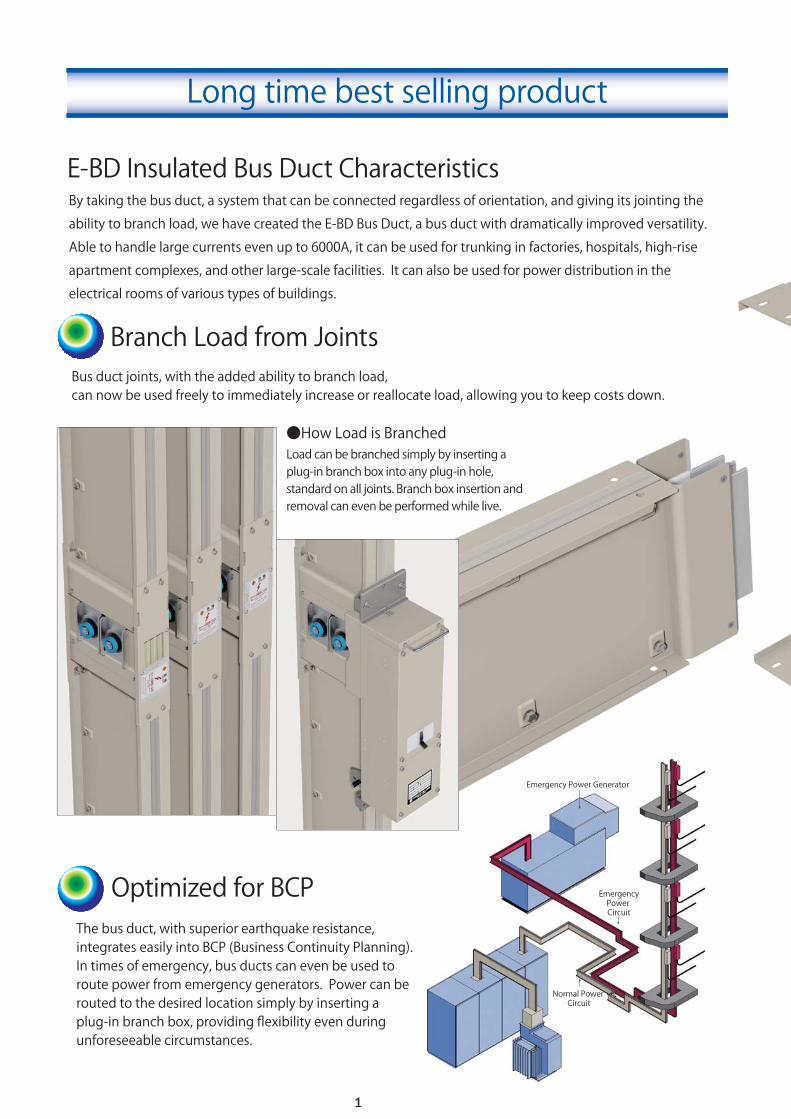
●How Load is BranchedLoad can be branched simply by inserting a plug-in branch box into any plug-in hole, standard on all joints. Branch box insertion and removal can even be performed while live.
Branch Load from JointsBus duct joints, with the added ability to branch load, can now be used freely to immediately increase or reallocate load, allowing you to keep costs down.
Optimized for BCPThe bus duct, with superior earthquake resistance, integrates easily into BCP (Business Continuity Planning). In times of emergency, bus ducts can even be used to route power from emergency generators. Power can be routed to the desired location simply by inserting a plug-in branch box, providing flexibility even during unforeseeable circumstances.
Emergency Power Generator
EmergencyPower Circuit
Normal Power Circuit
By taking the bus duct, a system that can be connected regardless of orientation, and giving its jointing the
ability to branch load, we have created the E-BD Bus Duct, a bus duct with dramatically improved versatility.
Able to handle large currents even up to 6000A, it can be used for trunking in factories, hospitals, high-rise
apartment complexes, and other large-scale facilities. It can also be used for power distribution in the
electrical rooms of various types of buildings.
1
E-BD Insulated Bus Duct Characteristics
Long time best selling product
3rd Floor
7th Floor
5th Floor
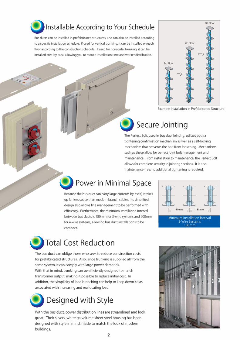
Secure JointingThe Perfect Bolt, used in bus duct jointing, utilizes both a
tightening confirmation mechanism as well as a self-locking
mechanism that prevents the bolt from loosening. Mechanisms
such as these allow for perfect joint bolt management and
maintenance. From installation to maintenance, the Perfect Bolt
allows for complete security in jointing sections. It is also
maintenance-free; no additional tightening is required.
Total Cost ReductionThe bus duct can oblige those who seek to reduce construction costs for prefabricated structures. Also, since trunking is supplied all from the same system, it can comply with large power demands. With that in mind, trunking can be efficiently designed to match transformer output, making it possible to reduce initial cost. In addition, the simplicity of load branching can help to keep down costs associated with increasing and reallocating load.
Installable According to Your ScheduleBus ducts can be installed in prefabricated structures, and can also be installed according
to a specific installation schedule. If used for vertical trunking, it can be installed on each
floor according to the construction schedule. If used for horizontal trunking, it can be
installed area-by-area, allowing you to reduce installation time and worker distribution.
Designed with StyleWith the bus duct, power distribution lines are streamlined and look great. Their silvery-white galvalume sheet steel housing has been designed with style in mind, made to match the look of modern buildings.
Example Installation in Prefabricated Structure
Power in Minimal SpaceBecause the bus duct can carry large currents by itself, it takes
up far less space than modern branch cables. Its simplified
design also allows line management to be performed with
efficiency. Furthermore, the minimum installation interval
between bus ducts is 180mm for 3-wire systems and 200mm
for 4-wire systems, allowing bus duct installations to be
compact.
Minimum Installation Interval3-Wire Systems180mm
180mm 180mm
2

The most important thing during bus duct installation is making sure that joint bolts are tightened correctly. With Kyodo KY-Tec’s revolutionary Perfect Joint System, the joint bolts are automatically tightened and installed correctly, regardless of who installs jointing or the conditions under which it is installed. Furthermore, with the Perfect Joint System, the installation status of the joint bolts can be checked simply by looking at them.
The PS torque bolt is a double-headed bolt that allows for tightening torque management. Upon reaching the specified torque, the outer head will twist off.
Before Tightening
Removing the Red Plate
When tightening the outer bolt head, upon reaching the specified torque, the outer head will twist off and the red ring will detach. After that, breaking the red plate will cause the self-locking mechanism to activate. Once the red plate has been removed, the bolt can no longer be loosened.
The PS torque bolt is a bolt used for securing conductors in jointing between the bus duct and attached equipment.If a general tool is used to tighten the red outer bolt head, when the specified torque is reached, the outer bolt head will twist off.The outer head that twists off is made of plastic, so it is electrically and mechanically safe.The PS torque bolt has torque management capabilities that allow for tightening to always be perfect.It also allows for tightening status to be checked simply through visual inspection.
After Tightening
Before Tightening
After Tightening
If properly tightened, each perfect bolt will only have the blue ring still attached.
Bolt inspection can be performed simply by visually confirming that only the blue rings remain on all perfect bolts.
Manage E-BD bus duct joint bolt functions perfectly
The Perfect Bolt
Create the best connections using tightening torque management
The Perfect Joint System
The PS Torque Bolt
3

Transformer
Transformer Connection Box
Branch Box
Circuit Breaker Box
Transformer
DistributionBoard
90
45
Neodymium Magnet Sensor
LED Lamp(Blinks to alert)
Temperature Sensor
Switchboard Setup
●Factories● Buildings
Switchboard
Boardless Setup
The E-Support System is a breakthrough system for minimizing the bus duct installation interval.
And to make installation even easier, we have made it so that all installation procedures can now be performed from the front of the unit. Accordingly, systems can now also be installed close to walls.
This system has also been optimized for installing multiple lines in narrow EPS.
After installing temperature sensor units in places where you want temperature to be measured, connect the cables to each sensor, and then begin monitoring temperature.On the system display, you can see the temperature readout at each measurement point, as well as the trend graph and the warning history, each of which can be output as a form on demand.This system makes it possible to monitor the temperature of bus duct joints and other parts in real time.
(PAT. 4693894、4698760)
● Common Support BracketCommon support brackets can only be installed on the front. The bolts used in it are coach bolts.
● Spring-Disengage JigBy using the above jig to disengage springs, the tightening nuts (black) on support bolts can be loosened and springs can easily be disengaged from in front of the system.
We want to keep electrical rooms in buildings and factories as small as possible while also increasing the amount of effectively usable space. By giving circuit breaker and switchboard capabilities to bus duct lines, we have conserved the space that is normally needed for switchboards while also reducing facility costs. The transformer and switchboard facilities on each line can be managed together, simplifying maintenance and helping to reduce any associated running costs.
Boardless Power Distribution
Floor Support System
Common Support Bracket
With Built-In Switchboard Capabilities
E-Support System For Simplified Floor Support System Installation
MLT Temperature Monitoring SystemSee Bus Duct Temperatures with the
4
Branch Box
Transformer
Circuit Breaker Box

The Kyodo KY-Tec Bus Duct is a straight bus duct with various types of joiners and units. By combining them, you can make routes with virtually any shape.
Bus Duct Route Overview
Cable Feed-In Unit
Vertical Support
Terminal End Section
HZ Unit
Plug-In Branch Box
HL Joiner
Wall-Penetrating Section
Transformer Connection Box
HLVL Unit
VZ Unit
Straight Bus Duct
Plug-In Joiner
VL Joiner
Phase Transposition Unit
Terminal Sectionwith Flanged End
5

Joiner Side Plate
Aluminum Section
Rated Current(A) W
(mm)H
(mm)Mass
(kg/m)W
(mm)H
(mm)Mass
(kg/m)3-Phase 1-Phase
Conductor Dimensions(mm)
3-Wire System 4-Wire SystemDWG
Rated Current(A)
W(mm)
H(mm)
Mass(kg/m)
W(mm)
H(mm)Mass
(kg/m)3-Phase 1-Phase
3-Wire System 4-Wire SystemDWG
Conductor Dimensions(mm)
100100100100
100100100100
100100100100100
110130145170
180220260310
360390430470570
17222633
35465669
778697106132
120120120120
120120120120
120120120120120
110130145170
180220260310
360390430470570
20273240
44587188
99110123137171
8 × 40 × 18 × 60 × 18 × 75 × 18 × 100 × 1
8 × 110 × 18 × 150 × 18 × 190 × 18 × 240 × 1
8 × 135 × 28 × 150 × 28 × 170 × 28 × 190 × 28 × 240 × 2
800100012001500
1600200025003000
35004000450050006000
1000120015001600
2000250030003500
-----
A × B × Naaaa
aaaa
bbbbb
100100100100
100100100100100
100100100100100
110130145170
205220260310370
430470530590690
11121417
2022263137
4247535969
120120120120
120120120120120
120120120120120
110130145170
205220260310370
430470530590690
12141619
2326313745
5257658285
60080010001200
15001600200025003000
35004000450050006000
800100012001500
16002000250030003500
-----
aaaa
aaaaa
bbbbb
8 × 40 × 18 × 60 × 18 × 75 × 18 × 100 × 1
8 × 135 × 18 × 150 × 18 × 190 × 18 × 240 × 18 × 300 × 1
8 × 170 × 28 × 190 × 28 × 220 × 28 × 250 × 28 × 300 × 2
Ratings and Specifications
Indoor Unit Cross Section Indoor Unit External Dimensions
● Rated Short-Time Withstand Current (JIS Example Reference for 3-Phase Units)
Aluminum Conductor Bus Duct
Copper Conductor Bus Duct
※On our standard bus duct, the cut surface of the sheet steel exposes the iron base material, so it may develop red rust. However, the sacrificial anticorrosion effect of the zinc, which covers the surface from the time the metal is cut, prevents rust from spreading through the iron.※The special second digit in the IP code, “4”, indicates that the unit is built such that water cannot penetrate sections receiving current.
*The mass above has been approximately calculated for indoor units with steel housing.*The dimensions for horizontally-oriented units are the same as above.
●5Y7/1 (Semigloss)
●Galvalume Sheet Steel
※Color can be selected as an option. However, even if color is selected, joiner side plates and aluminum sections will remain their standard colors.※Whisker-free units are also available. Please inquire for more details.
CAUTION
Bus Duct Dimensions & Specifications
For specific dimensions, download drawings from the DXF standard drawing library on our website:http://www.ky-tec.co.jp
3-Wire System 4-Wire System
Diagram A (Single-Level System)
Diagram B (Double-Level System)
A × B × N
●Applicable Standards :JIS C 8364 IEC 60439-1 IEC 60439-2●Degrees of Protection:Indoor: IP 3X Outdoor: IP 44 (Not including ventilated sections)●Power Distribution Configuration ●Rated Voltage :600V (AC) 750V (DC)●Rated Current : 3-Phase 600A ~ 6000A 1-Phase 800A ~ 3500A● Conductors :Aluminum or copper conductors (electroplated)●Insulation :Heat-resistant multi-layered polyester sheet●Housing :Zinc-plated sheet steel or galvalume sheet steel with extruded aluminum housing●Grounding Type :Case grounding●Standard Finish(Surface):Sheet steel: 5Y7/1 (semigloss) or galvalume sheet steel Aluminum: Electrolytic coloration (Stainless coloration with alumite treatment)
Rated Current (A)
600 ~ 10001200 ~ 16002000 ~ 3500
220.1 sec
4260
221 sec
4260
Rated Short-Time Withstand Current (kA)
4000 ~ 6000 90 90
6
:3-Phase 3-Wire, 3-Phase 4-Wire, 1-Phase 3-Wire, 1-Phase 2-Wire, DC
Straight Bus Ducts, Joiners, Units
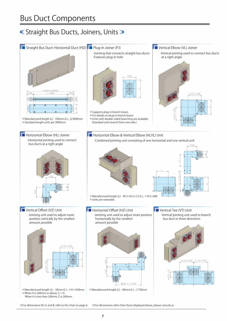
*Supports plug-in branch boxes*For details on plug-in branch boxes*Units with double-sided branching are available. (Standard units branch from one side.)
*Manufactured length (L): 430mm≦L≦3000mm*Standard-length units are 3000mm.
※For dimensions other than those displayed above, please consult us.
■ Straight Bus Duct: Horizontal Duct (HD) ■ Plug-In Joiner (PJ)
■ Horizontal Elbow (HL) Joiner ■ Horizontal Elbow & Vertical Elbow (HLVL) Unit
■ Vertical Elbow (VL) Joiner
■ Vertical Offset (VZ) Unit
■ Horizontal Offset (HZ) Unit ■ Vertical Tee (VT) Unit
*Manufactured length (L): W/2+H/2+2.5≦L<H/2+680*Units are reversible.
*Manufactured length (L): 60mm≦L<730mm*Manufactured length (L): 50mm≦L<H+630mm*When H is 260mm or above, Z = H. When H is less than 260mm, Z is 260mm.
Bus Duct Components
7
-Jointing that connects straight bus ducts -Features plug-in hole
-Vertical jointing used to connect bus ducts at a right angle
-Horizontal jointing used to connect bus ducts at a right angle
-Combined jointing unit consisting of one horizontal and one vertical unit
-Jointing unit used to adjust route position vertically by the smallest amount possible
-Jointing unit used to adjust route position horizontally by the smallest amount possible
-Vertical jointing unit used to branch bus duct in three directions
※For dimensions W, H, and B, refer to the chart on page 6.

Other Units
*Dimensions in parenthesis ( ) are for double-level systems.*All 4-wire systems use the dimensions in parenthesis.
*Only usable on 3-wire systems with aluminum conductors.
*Dimensions in parenthesis ( ) are for double-level systems.
■ Horizontal Tee (HT) Unit
■ Phase Transposition Unit ■ Dimension Adjustment Unit
■ New Horizontal Tee (N-HT) Unit
■ Reducer Joiner ■ Type F Expansion (F-EXP) Unit
※For dimensions W, H, and B, refer to the chart on page 6. ※For dimensions other than those displayed above, please consult us.
*Only usable on single-level 3-wire systems with aluminum conductors.
Can be used to adjust dimensionsbetween 260 and 420mm.(When both SAJ and SAJL have arrived on site.)
Reversing phase sequence (R-S-T, starting from the left) is also possible.
Can be used to adjust dimensions between 750 and 950mm.
*Only usable on units with single-level conductors.*There are two ways to align the units: The bottom surfaces can be aligned (as shown in the image above), or the centers of the units can be aligned.
SAJ:300±40SAJL:380±40 SAJH:850±100
8
-Horizontal jointing unit used to branch bus duct in three directions -A reduced version of the HT unit to the left, but without the protruding upper section
-Jointing unit used for rearranging phase sequence within the bus duct.
-Jointing unit used for adjusting bus duct dimensions on-site.
-Jointing used to reduce rated current in the middle of a bus duct circuit
-Used to pass through expanded sections of buildings -Also used to counteract irregularities in the building foundation caused by ground subsidence

Boardless ShaftStar is a registered trademark of Kyodo KY-Tec.
Bus Duct Division TBC Bldg. 7F, Higashi 2-27-10 Shibuya-ku, Tokyo, Japan 150-0011 http://www.ky-tec.co.jp
TEL (+81) 3-3409-2333
FAX (+81) 3-3409-2339
This catalogue is up to date as of March 2014.
Product details are subject to change without notice.
Images used in this catalogue are simulated.
Headquarters
Higashi 3-24-12, Shibuya-ku, Tokyo, Japan 150-0011 http://www.ky-tec.co.jp
1151