busbar earthing
TRANSCRIPT
8/6/2019 BusBar Earthing
http://slidepdf.com/reader/full/busbar-earthing 1/19
National Grid Busbar Protection for
Technical 400 kV and 275 kV DoubleSpecification Busbar Switching Stations
NGTS 3.6.3
Issue 3
December 1996
CONTENTS Page
Foreword .....................................................1
Scope...........................................................1
References .................................................1
General Requirements.............................1
Performance Requirements ....................6
Test Requirements ...................................8
Technical Data of Equipment
Submitted for Approval..............................9
Contract Specified Options ......................9
Appendices ..............................................11
Figures ......................................................15
Authorised for Issue by:
M B Humphries
General Manager
Technology and Science Division
Uncontrolled
when Printed

8/6/2019 BusBar Earthing
http://slidepdf.com/reader/full/busbar-earthing 2/19
8 The National Grid Company plc 1996
No part of this publication may be reproduced,
stored in a retrieval system, or transmitted in
any form or by any means electronic, mechanical,
photocopying, recording or otherwise, without
the written permission of the NGC obtained from
the issuing location.
Registered Office
National Grid House
Kirby Corner Road
Coventry
CV4 8JY
Registered in
England and Wales
No. 2366977
Published by:
The National Grid Company plc
Burymead House
Portsmouth Road
Guildford, Surrey GU2 5BN
The contents of National Grid engineering documents are based onthe needs of National Grid and the conditions under which it operates.
It should not therefore be assumed that the specifications andrequirements stated therein necessarily meet the particular
circumstances and requirements of other organisations. Theprinciples set out in this document are for information only and
therefore National Grid is not liable to customers/suppliers for any lossor damage resulting from reliance on the contents. It is the
responsibility of such external organisations to check that thedocument is the latest version and is appropriate for their purposes.
Uncontrolled
when Printed
8/6/2019 BusBar Earthing
http://slidepdf.com/reader/full/busbar-earthing 3/19
NGTS 3.6.3
Page 3 Issue 3
December 1996
BUSBAR PROTECTION FOR 400 kV AND 275 kV DOUBLE BUSBAR SWITCHING STATIONS
FOREWORD
This Specification defines The National Grid Company plc's (NGC) technical requirements for BusbarProtection. This Specification is part of a hierarchical structure of documentation comprising three levels
of Technical Specification. This Document is a Level Three Specification.
1 SCOPE
This Specification describes the functional and performance requirements and the facilities to be provided
exclusively for the protection of busbars at 400 kV and 275 kV double busbar switching stations.
2 REFERENCES
This Specification makes references to and should be read in conjunction with the following documents:
IEC 255-1-00 - All or Nothing Electrical Relays.
IEC 255-0-20 - Contact Performance of Electrical Relays.
IEC 255-6 - Measuring Relays and Protection Equipment.
IEC 255-7 - Test and Measurement Procedures for Electromechanical All or Nothing Relays.
IEC 255-13 - Biased Differential Relays.
NGTS 1- Overview National Grid System.
NGTS 2.1 - Substations.
NGTS 2.6 - Protection.
NGTS 2.7 - Substation Control Systems.
NGTS 3.2.4 - Current Transformers.
NGTS 3.1.1 - Substation Interlocking Systems.
NGTS 3.6.5 - Intertripping and Protection Signalling.
NGTS 3.6.8 - Circuit-Breaker Fail Protection.
NGTS 3.6.15 - Trip Relays and Trip Relay Resetting.
NGTS 3.7.24 - Alarm and Event logging Legends.
NGTS 3.12.2 - 110 V D.C. Supplies.
3 GENERAL REQUIREMENTS
3.1 Functional Requirements
The busbar protection system shall comprise main protections and CT supervision as described in Section
3.1.1 & 3.1.2.
Two independent fault detecting systems shall operate into two independent tripping systems as described
in Section 3.1.3 to provide a complete protection system as shown in Figures 1,2 and 3.
The arrangement of the busbar protection shall be such that limited protection can be maintained by the use
of one fault detecting system only, should the need arise (eg during investigation of a fault on a zone of the
protection or during maintenance). This shall be achieved by employing temporary connections to by-pass
the fault detecting system associated with the zone under investigation.
The equipment for busbar protection shall be electrically and physically independent from other equipmentas far as practicable. Separate relay panels or racks and multicore cables shall be employed and the wiring
and terminals shall as far as reasonably practicable, be segregated from other circuits.
Uncontrolled
when Printed
8/6/2019 BusBar Earthing
http://slidepdf.com/reader/full/busbar-earthing 4/19
NGTS 3.6.3
Page 4 Issue 3
December 1996
3.1.1 Busbar Fault Detection Systems
The busbar protection shall have two, independent, fault detection systems. The measuring arrangements
within the fault detection system shall be effectively duplicated at 400 kV and 275 kV and arranged in a two-
out-of-two tripping logic. The overall tripping logic shall be such that both fault detection systems must
operate before correct tripping of circuit-breakers can occur (refer to Figures 1, 2 & 3).
Each fault detection system shall provide fully discriminative current differential protection for phase-to-phase
and phase-to-earth faults occurring within the busbar zone associated with any busbar section. The
measuring relays shall comply with the requirements of IEC 255-6. If a biased differential principle is used,
the protection shall also comply with the requirements of IEC 255-13.
At least one fault detection system shall discriminate between the busbar sections of a protected busbar
station and both fault detection systems shall discriminate between faults on the protected busbar station
and faults elsewhere on the primary system. The fault detection system discriminating between sections
of busbar, shall be known as the discriminating system and the protected sections of busbar shall be known
as discriminating zones. The other fault detection system shall be known as the check system and, for the
case of single check zone substations, shall discriminate between faults within and external to the protectedbusbars of the complete substation. Where necessary, multiple check zones may be specified on the
contract.
For high impedance circulating current schemes, voltage limiting devices shall be provided if the peak
voltage developed across the high impedance relay circuit during a busbar fault condition is greater than 3
kV. The characteristic provided shall be declared by the manufacturer.
3.1.2 Current Transformer Supervision
Open-circuited busbar protection current transformer windings or connections shall be detected by
supervision of the current transformer secondary wiring circuits. CT supervision is required in both the check
and discriminating zones.
The CT supervision relay shall be capable of detecting `spill' current in all three separate phases.
The CT supervision shall be arranged to give an alarm only and not to short-circuit the bus-wires. The fault
detection and supervision system shall be capable of withstanding this condition continuously for the
secondary current which corresponds to the maximum primary load condition.
In this situation, security against maloperation of the protection is provided by the non-operation of the other
fault detecting system.
Initiation of the alarm shall be time delayed such that it is not annunciated for genuine busbar faults nor for
external faults. A time delayed output covering the range 1.0 - 10.0 s shall be provided. Where this is not
the case a suitable external timer shall be provided.
3.1.3 Protection System
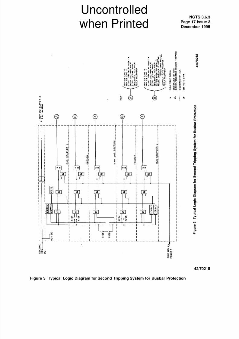
The overall protection system shall comprise two separately energised independent tripping systems. Each
tripping system shall be initiated for both check and discriminating zone fault detection systems in a two-
out-of-two tripping logic, and operate the appropriate circuit breakers via a per circuit trip relay(s).
These trip relays shall be of the high burden electrically reset latching type, and shall be provided with
automatic resetting facilities as described in NGTS 3.6.15.
Where due to burden limitations of the fault detection relay output contact, high burden trip relays cannot
be driven directly, then a high speed, double pole switched, self reset trip repeat relay(s) with hand reset
operation indicator, and with performance as specified in Section 4.4, may be applied to operate the triprelay(s).
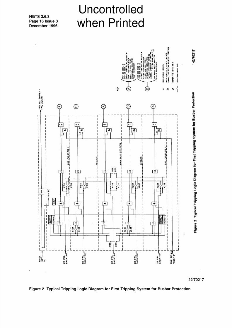
Provision shall be made within the first tripping system for the circuit breaker fail protection to initiate
backtripping of all contiguous circuit breakers, see Figure 2.
Uncontrolled
when Printed
8/6/2019 BusBar Earthing
http://slidepdf.com/reader/full/busbar-earthing 5/19
NGTS 3.6.3
Page 5 Issue 3
December 1996
Discriminative tripping (and backtripping from circuit breaker fail protection) shall be achieved utilizing
disconnector auxiliary switches or repeat relay contacts as specified in Section 3.2.3.
The operation of any single trip relay shall not result in the tripping of more than one circuit.
When a busbar fault occurs, all circuit-breakers connected to the faulted busbar shall be trippedsimultaneously, whether they can feed fault current or not. The rating of all busbar tripping contacts,
connections and fuses/MCBs shall be suitable for meeting this requirement.
Typical tripping logic diagrams for the first and second tripping systems are shown in Figures 2 and 3
respectively.
3.2 Inputs
3.2.1 Power Supply
The tripping systems shall be designed to operate from a 110 V (nominal) D.C. battery specified in
NGTS 3.12.2. Each tripping system shall be provided with a separately fused supply fed from differentbatteries.
If an auxiliary energising supply is required by a fault detecting system, it shall be taken from the tripping
system supply to which the fault detecting system is connected.
3.2.2 Current Transformers
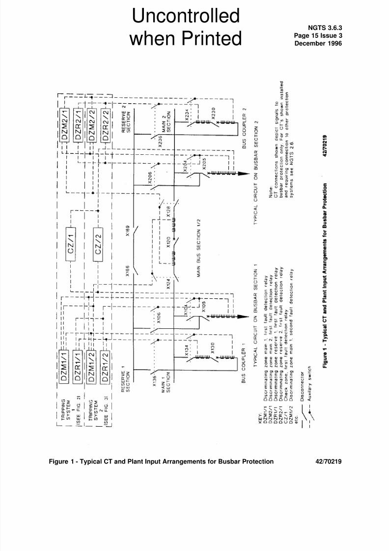
A typical current transformer arrangement, depicting signals to the busbar protection system is shown in
Figure 1. Details of other current transformer arrangements acceptable to NGC are given in NGTS 2.1 and
NGTS 2.6.
For high impedance circulating current protection, class `X' Type `B' CTs in accordance with NGTS 3.2.4
shall be provided for both discriminating and check zones. For low impedance schemes alternative CT
cores may be suitable and shall be specified by the manufacturer.
Separate current transformers shall be utilized for each of the check and discriminating systems.
There shall be no disconnector auxiliary switches or repeat relay contacts in the current transformer circuits
of the check system.
When disconnector auxiliary switches or repeat relays are used for switching current transformer circuits,
they shall also be used to short to earth and disconnect the current transformer secondary wiring from any
common A.C. bus wiring when the primary circuit is isolated. The timing of such auxiliary switches or
repeat relays shall comply with the requirements of Section 3.2.3.
Check zone current transformers shall be provided on outgoing or incoming circuits. Bus Section and Bus
Coupler circuit-breakers shall not have check zone current transformers, except where multiple check zones
are specified.
Discriminating zone current transformers shall be provided on all outgoing and incoming circuits. Overlapping
discriminating zone current transformers shall also be provided on Bus Section or Bus Coupler bays, (see
Figure 1). In order to prevent incorrect operation of the busbar protection under certain fault conditions within
the overlapping zone, auxiliary switches shall be provided in the CT circuits associated with busbar coupler
and busbar section disconnectors. Suitable interlocking arrangements as described in NGTS 3.1.1 shall
be provided for the busbar coupler and busbar section circuit breakers and their respective disconnectors
to ensure no section of busbar is unprotected during switching operations.
Current transformer mounting and polarity markings shall be in accordance with NGTS 2.1.
The secondary windings of each three phase set of current transformers shall be starred at the current
transformer terminal block normally located at the switchgear. The position of the star point, with respect
to the protected busbar, shall be in accordance with NGTS 2.1.
Uncontrolled
when Printed
8/6/2019 BusBar Earthing
http://slidepdf.com/reader/full/busbar-earthing 6/19
NGTS 3.6.3
Page 6 Issue 3
December 1996
3.2.3 Contact Initiations
(i) Primary disconnector auxiliary switches or repeat relay contacts shall be provided to satisfy the busbar
protection system requirements stated in Section 3.1.3 and 3.2.2 and shown in Figures 1,2 and 3.
The operating sequence of disconnector auxiliary switches or disconnector repeat relay contacts used in
current transformer circuits and in 110 V D.C. tripping circuits shall be such that the auxiliary switches or
repeat relay contacts operate:
(a) Before reaching the pre-arcing distance on closing the disconnector.
(b) After the pre-arcing distance has been exceeded on opening the disconnector.
Combinations of normally open and normally closed auxiliary switches or repeat relay contacts from the
same disconnector shall `break' before `make' both for opening and closing the disconnector.
Where repeat relay contacts are used in lieu of disconnector auxiliary switches, the repeat relays shall beof the latched type. The position of the primary plant contacts with respect to the repeat relay contacts
shall be monitored such that any discrepancy from the normal relative positions will cause an alarm to be
annunciated. The relay energising supply shall be supervised. Loss of this supply shall initiate an alarm.
It shall be possible to determine whether the relay is simulating an open or closed disconnector, by
observation of a suitable indicating device on the relay.
(ii) An input shall be provided from the circuit breaker fail protection of each circuit breaker (see NGTS 3.6.8)
to initiate back-tripping of all other circuit breakers associated with the same busbar zone(s) via the busbar
protection first tripping system.
3.2.4 D.C. Initiations
The protection system shall be provided with inputs to receive D.C. signals for the following:-
Trip relay reset (110 V D.C.).
3.3 Outputs
3.3.1 Trip Outputs
The trip relays of each tripping system shall be provided with output contacts for initiation of the following:-
(i) Tripping the associated local circuit-breaker(s).
(ii) Circuit-breaker fail protection.
(iii) Intertripping to the associated remote circuit-breaker(s). (Two channels each being double pole
switched for feeder circuits).
Uncontrolled
when Printed
8/6/2019 BusBar Earthing
http://slidepdf.com/reader/full/busbar-earthing 7/19
NGTS 3.6.3
Page 7 Issue 3
December 1996
(iv) Unblocking/accelerating or unstabilizing of feeder protection.
Facilities shall be provided to select or deselect direct tripping of remote circuit breakers from intertripping,
unblocking, acceleration or unstabilising, as part of the busbar protection tripping scheme.
Selection of intertripping, unblocking/acceleration, or unstabilizing direct from the busbar protection triprelays shall be as specified by NGC on particular contracts.
Where direct tripping is deselected, then tripping of the remote circuit breaker(s) shall be initiated via the
Circuit Breaker Fail Protection (see NGTS 3.6.8).
3.3.2 Additional Outputs
The protection system shall be capable of providing outputs for initiation of the following:-
(i) Disconnector sequential isolation.
(ii) Trip relay reset.
(iii) Lockout of auto reclosure.
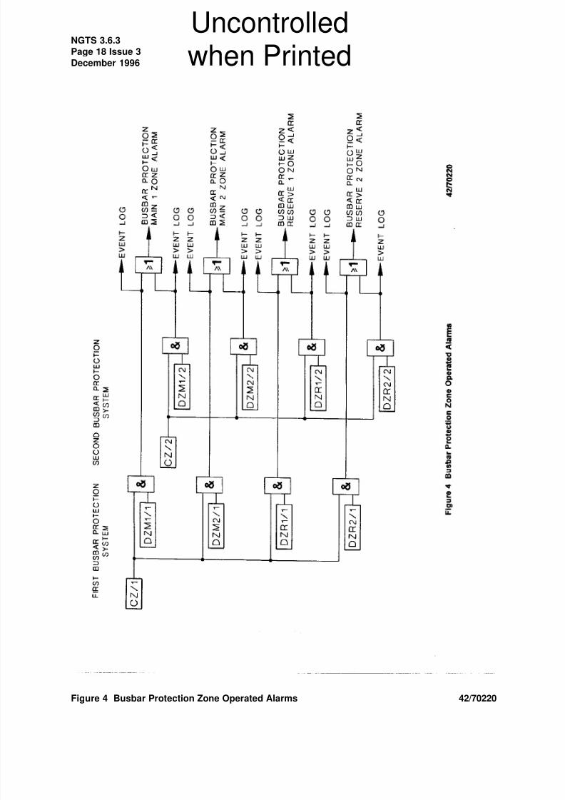
3.3.3 Alarm Outputs
Protection operation or failure shall be annunciated through the substation alarm and event logging system.
The following protection alarm outputs shall be provided:-
(i) Busbar protection zone operation (refer to Figure 4).
(ii) Trip relay operated indication (where required).
(iii) Protection supply supervision alarm for each fused supply (refer to NGTS 2.6).
(iv) CT Supervision.
(v) Disconnector Auxiliary Switch repeat relay discrepancy alarm (where required).
If the protection equipment is of an electronic type, an alarm output of equipment inoperative shall be
provided for the loss of D.C. auxiliary energising supply and internal relay failures.
3.3.4 Fault Recorder
Operation of the busbar protection trip relays shall trigger, and be recorded on, a fault recorder.
3.4 Operator Interface
The following facilities shall be provided for the protection system, where appropriate, in accordance with
NGTS 2.6:-:
(i) Setting Facilities.
(ii) Indications.
(iii) Isolation and Testing Facilities.
Facilities shall be provided to enable each relay element current to be measured where applicable.
Uncontrolled
when Printed
8/6/2019 BusBar Earthing
http://slidepdf.com/reader/full/busbar-earthing 8/19
NGTS 3.6.3
Page 8 Issue 3
December 1996
Each of the three phase connections from every set of current transformers shall pass through an isolating
link or equivalent before being connected to any relay, common bus-wire or busbar selector auxiliary switch.
In one position the link shall give normal connection and in the other position it shall short out the current
transformer and it shall isolate the current transformer from its associated phase buswire. The three phase
set of links, shall have suitable test terminals.
The test links shall normally be physically located at the associated circuit-breaker marshalling kiosk, or,
in the case of 400 kV busbar stations where circuit-breaker marshalling kiosks may not be provided, at the
individual relay room busbar protection rack, panel or primary marshalling cubicle.
Where two or more check zones are specified, the test links associated with the current transformers
installed at the reserve busbar sectioning point shall be physically located in a marshalling kiosk or box
which shall be provided adjacent to the sectioning point.
Where the circuit-breaker fail protection utilises the busbar protection trip system for back tripping, sufficient
isolation facilities shall be provided to enable complete per circuit trip testing on an individual circuit-breaker
fail system without the risk of backtripping to other circuits.
Trip circuits in the busbar protection panel or rack shall be fully insulated or shrouded on the trip relay andtrip coil(s) sides of fuses or links.
4 PERFORMANCE REQUIREMENTS
The busbar protection supplier shall provide a design report detailing the protected equipment, protection
system, calculations for setting and performance details.
The performance requirements for the fault detection, ct supervision and high speed trip repeat relays are
specified below.
4.1 General
The protection system shall perform correctly in accordance with the requirements of this Specification for
the range of power system conditions specified in NGTS 1 and the range of environmental conditions
specified in NGTS 2.6. In addition the performance of the protection shall not be adversely affected by the
conditions of current transformer saturation and magnetising inrush.
4.2 Busbar Fault Detection System
4.2.1 Sensitivity
Fault setting requirements shall be specified by NGC as part of the contract for busbar protection.
The rated stability limit shall be based on a maximum through fault current for both phase faults and earthfaults of not less than that corresponding to the associated switchgear rated short-time current, irrespective
of the existing or anticipated fault levels at particular stations. The maximum through fault currents and the
rated maximum earth fault current for particular system voltages are as listed in NGTS 1.
For voltage calibrated relays the selected relay circuit setting voltage shall be the nearest setting available,
equal to, or higher than, the calculated stability voltage.
4.2.2 Reliability
The busbar protection shall be stable for all Primary System faults and other conditions with the exception
of a fault internal to its zone of protection.
Uncontrolled
when Printed
8/6/2019 BusBar Earthing
http://slidepdf.com/reader/full/busbar-earthing 9/19
NGTS 3.6.3
Page 9 Issue 3
December 1996
The busbar protection system shall not respond to the D.C. component present in fault current in such a
way as to make the relay unstable for through faults.
The busbar protection system shall not be affected by harmonic circulating currents. Refer to NGTS 1 for
the levels of harmonic currents.
The busbar protection system shall be stable in the event of an external fault with fault current up to the
rated stability limit and a saturated current transformer. Under these conditions a voltage developed across
the relay or current through the relay shall not result in its operation.
4.2.3 Operating Time
The operating time of busbar protection relay shall, when energised on its own (ie not in conjunction with
current transformers) from a resistance controlled test supply, not exceed 30 ms at a setting multiple of two
times or 17 ms at a setting multiple of five times.
4.2.4 Thermal Rating
The busbar protection system shall be continuously rated for the condition in which one relay circuit is being
supplied with rated current corresponding to maximum load current.
4.2.5 Drop Off/Pick up Ratio
The drop off/pick up ratio of the protection relay shall not be less than 0.8.
4.2.6 Resetting Time
The resetting time of the protection relay shall not be greater than 50 ms.
4.2.7 Accuracy
The assigned error for the protection relay shall not be greater than 5%.
4.2.8 Output Contact Ratings
Contact ratings shall be as follows:-
Busbar protection relay, make and carry for 200 ms 2500 W at 125 V D.C.
In general the contact performance should comply with the requirements of IEC 255-0-20, Category III.
4.2.9 CT Supervision Sensitivity
The CT supervision shall normally be set to operate at between 2 and 10 per cent of 2000 amp at 400 kV,
and at between 2 and 10 per cent of 1000 amp at 275 kV, the lower setting being related to a discriminating
zone with one primary circuit only connected and the upper setting to the check zone, or to parallelled
discriminating zones with all primary circuits connected.
4.3 High Speed Trip Repeat Relays (Double Pole Switched)
4.3.1 General
Repeat relays that perform a tripping function shall comply with the requirements of NGTS 3.6.15.
Uncontrolled
when Printed
8/6/2019 BusBar Earthing
http://slidepdf.com/reader/full/busbar-earthing 10/19
NGTS 3.6.3
Page 10 Issue 3
December 1996
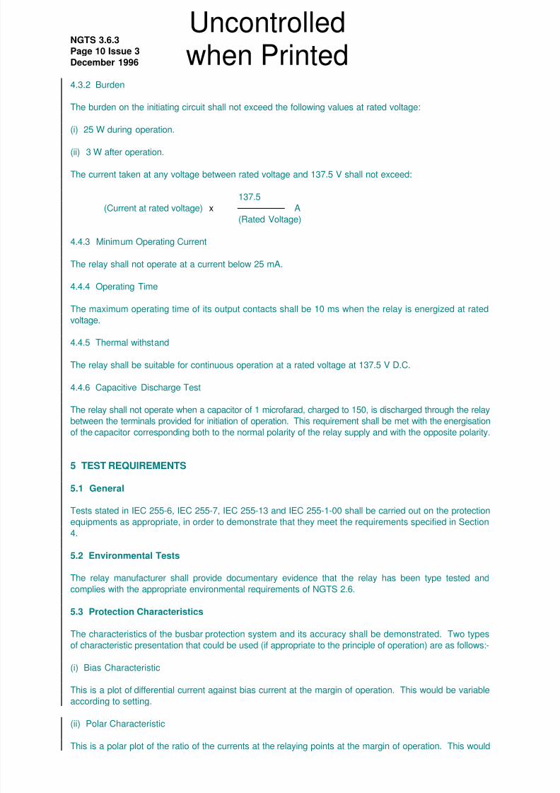
4.3.2 Burden
The burden on the initiating circuit shall not exceed the following values at rated voltage:
(i) 25 W during operation.
(ii) 3 W after operation.
The current taken at any voltage between rated voltage and 137.5 V shall not exceed:
137.5
(Current at rated voltage) x A
(Rated Voltage)
4.4.3 Minimum Operating Current
The relay shall not operate at a current below 25 mA.
4.4.4 Operating Time
The maximum operating time of its output contacts shall be 10 ms when the relay is energized at rated
voltage.
4.4.5 Thermal withstand
The relay shall be suitable for continuous operation at a rated voltage at 137.5 V D.C.
4.4.6 Capacitive Discharge Test
The relay shall not operate when a capacitor of 1 microfarad, charged to 150, is discharged through the relay
between the terminals provided for initiation of operation. This requirement shall be met with the energisation
of the capacitor corresponding both to the normal polarity of the relay supply and with the opposite polarity.
5 TEST REQUIREMENTS
5.1 General
Tests stated in IEC 255-6, IEC 255-7, IEC 255-13 and IEC 255-1-00 shall be carried out on the protection
equipments as appropriate, in order to demonstrate that they meet the requirements specified in Section
4.
5.2 Environmental Tests
The relay manufacturer shall provide documentary evidence that the relay has been type tested and
complies with the appropriate environmental requirements of NGTS 2.6.
5.3 Protection Characteristics
The characteristics of the busbar protection system and its accuracy shall be demonstrated. Two types
of characteristic presentation that could be used (if appropriate to the principle of operation) are as follows:-
(i) Bias Characteristic
This is a plot of differential current against bias current at the margin of operation. This would be variableaccording to setting.
(ii) Polar Characteristic
This is a polar plot of the ratio of the currents at the relaying points at the margin of operation. This would
Uncontrolled
when Printed
8/6/2019 BusBar Earthing
http://slidepdf.com/reader/full/busbar-earthing 11/19
NGTS 3.6.3
Page 11 Issue 3
December 1996
be variable according to setting and current magnitude.
5.4 Conjunctive Tests with Current Transformers
Tests shall be carried out to determine the limits of stability and operating time during transient saturation
of an equivalent current transformer. To obtain maximum flux in the current transformer, three faults shallbe applied at the point-on-wave which produces maximum offset of the current waveform before reversing
the point-on-wave and applying a further three faults.
6 TECHNICAL DATA OF EQUIPMENT SUBMITTED FOR APPROVAL
All equipment offered under the Contract shall be approved by NGC. Where NGC approval is required,
technical data shall be supplied in accordance with this specification and NGTS 2.6.
The contractor shall confirm that his equipment complies with the requirements as stated in NGTS 2.6 and
in this Specification, using "Statements of Compliance" attached to NGTS 2.6 and this Specification.
7 CONTRACT SPECIFIED OPTIONS
The following options are available for selection according to the requirements of the particular site and will
be specified in the contract documentation.
7.1 Direct remote tripping from busbar protection trip relays, see Section 3.3.1.
7.2 The fault setting, or primary operating current of the busbar protection, see Section 4.2.1.
7.3 The number of check zones, see Section 3.1.1.
Uncontrolled
when Printed

8/6/2019 BusBar Earthing
http://slidepdf.com/reader/full/busbar-earthing 12/19
NGTS 3.6.3
Page 12 Issue 3
December 1996
APPENDIX A
STATEMENT OF COMPLIANCE
NGTS 3.6.3 Busbar Protection
Contract Description:
Contract Number:
Protection System:
Enter details below of all major equipments used within the above system:
Mfr
Model
Type
Rated D.C.
Operating
Voltages
Rated A.C.
Current/
Voltage
Other
Details
Uncontrolled
when Printed
8/6/2019 BusBar Earthing
http://slidepdf.com/reader/full/busbar-earthing 13/19
NGTS 3.6.3
Page 13 Issue 3
December 1996
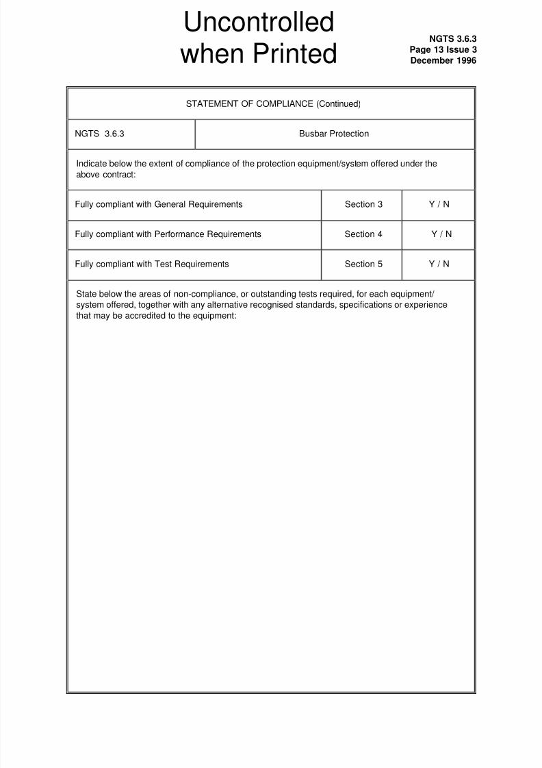
STATEMENT OF COMPLIANCE (Continued)
NGTS 3.6.3 Busbar Protection
Indicate below the extent of compliance of the protection equipment/system offered under the
above contract:
Fully compliant with General Requirements Section 3 Y / N
Fully compliant with Performance Requirements Section 4 Y / N
Fully compliant with Test Requirements Section 5 Y / N
State below the areas of non-compliance, or outstanding tests required, for each equipment/
system offered, together with any alternative recognised standards, specifications or experience
that may be accredited to the equipment:
Uncontrolled
when Printed

8/6/2019 BusBar Earthing
http://slidepdf.com/reader/full/busbar-earthing 14/19
NGTS 3.6.3
Page 14 Issue 3
December 1996
STATEMENT OF COMPLIANCE (Continued)
NGTS 3.6.3 Busbar Protection
State below any further relevant details or data for the equipment/system (ie Parameters, user
selectable options and features, additional facilities etc):
Uncontrolled
when Printed
8/6/2019 BusBar Earthing
http://slidepdf.com/reader/full/busbar-earthing 15/19
NGTS 3.6.3
Page 15 Issue 3
December 1996
Figure 1 - Typical CT and Plant Input Arrangements for Busbar Protection 42/70219
Uncontrolled
when Printed
8/6/2019 BusBar Earthing
http://slidepdf.com/reader/full/busbar-earthing 16/19
NGTS 3.6.3
Page 16 Issue 3
December 1996
42/70217
Figure 2 Typical Tripping Logic Diagram for First Tripping System for Busbar Protection
Uncontrolled
when Printed
8/6/2019 BusBar Earthing
http://slidepdf.com/reader/full/busbar-earthing 17/19
NGTS 3.6.3
Page 17 Issue 3
December 1996
42/70218
Figure 3 Typical Logic Diagram for Second Tripping System for Busbar Protection
Uncontrolled
when Printed
8/6/2019 BusBar Earthing
http://slidepdf.com/reader/full/busbar-earthing 18/19
NGTS 3.6.3
Page 18 Issue 3
December 1996
Figure 4 Busbar Protection Zone Operated Alarms 42/70220
Uncontrolled
when Printed
8/6/2019 BusBar Earthing
http://slidepdf.com/reader/full/busbar-earthing 19/19
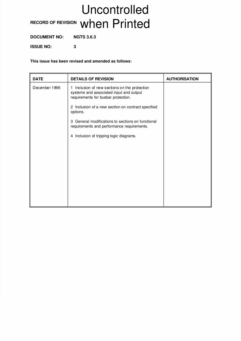
RECORD OF REVISION
DOCUMENT NO: NGTS 3.6.3
ISSUE NO: 3
This issue has been revised and amended as follows:
DATE DETAILS OF REVISION AUTHORISATION
December 1996 1 Inclusion of new sections on the protection
systems and associated input and output
requirements for busbar protection.
2 Inclusion of a new section on contract specified
options.
3 General modifications to sections on functional
requirements and performance requirements.
4 Inclusion of tripping logic diagrams.
Uncontrolled
when Printed