busbar protection reb650 product guide - megavar...protection functions include different types of...
TRANSCRIPT

Relion® 650 series
Busbar protection REB650Product Guide

Contents
1. 650 series overview........................................................3
2. Application.....................................................................3
3. Available functions..........................................................5
4. Differential protection....................................................11
5. Current protection........................................................11
6. Voltage protection........................................................12
7. Secondary system supervision.....................................12
8. Control.........................................................................13
9. Logic............................................................................15
10. Monitoring...................................................................16
11. Metering......................................................................18
12. Human Machine interface............................................18
13. Basic IED functions.....................................................19
14. Station communication................................................20
15. Hardware description..................................................22
16. Connection diagrams..................................................23
17. Technical data.............................................................24
18. Ordering for Customized IED.......................................48
19. Ordering for Configured IED........................................51
20. Ordering for Accessories.............................................53
Disclaimer
The information in this document is subject to change without notice and should not be construed as a commitment by ABB. ABB assumes no responsibility for any
errors that may appear in this document. Drawings and diagrams are not binding.
© Copyright 2013 ABB.
All rights reserved.
Trademarks
ABB and Relion are registered trademarks of the ABB Group. All other brand or product names mentioned in this document may be trademarks or registered
trademarks of their respective holders.
Busbar protection REB650 1MRK 505 290-BEN A
Product version: 1.3
2 ABB

1. 650 series overviewProtection for a wide range of applications, control ofswitching devices with interlocking, and monitoring can beprovided in one IED.
The 650 series IEDs provide both customized and configuredsolutions. With the customized IEDs you have the freedom tocompletely adapt the functionality according to your needs.
The 650 series IEDs provide optimum 'off-the-shelf', ready-to-use solutions. It is configured with complete protectionfunctionality and default parameters to meet the needs of awide range of applications for generation, transmission andsub-transmission grids.
The 650 series IEDs include:• Customized versions providing the possibility to adapt the
functionality to the application needs for protection andcontrol in one IED.
• Configured versions solutions are completely ready to useand optimized for a wide range of applications forgeneration, transmission and sub-transmission grids.
• Support for user-defined names in the local language forsignal and function engineering.
• Minimized rule based parameter settings based on defaultvalues and ABB's global base value concept. You onlyneed to set those parameters specific to your own installedand activated application.
• GOOSE messaging for horizontal communication onbumpless redundant station bus following IEC62439–3 ed2PRP.
• Extended HMI functionality with 15 dynamic three-color-indication LEDs per page, on up to three pages, andconfigurable push-button shortcuts for different actions.
• Programmable LED text-based labels.• Settable 1A/5A -rated current inputs.• Role based access control with independent passwords
and FTPS encrypted communication. Managedauthentication and accounting of all user activities.
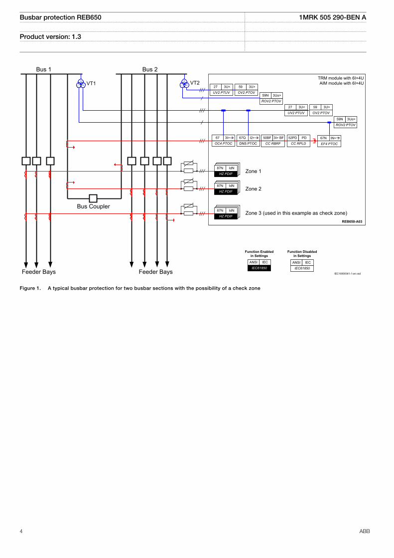
2. ApplicationThe numerical busbar protection REB650 IED provides itsusers with a wide variety of application opportunities.Designed primarily for the protection of single busbars with orwithout sectionalizers, it also offers high impedancedifferential protection for generators, autotransformers, shuntreactors and capacitor banks. The REB650 I/O capabilityallows you to protect up to three 3-phase high impedancedifferential protection zones with a single IED. Apparatuscontrol for up to 8 apparatuses with interlocking can beincluded in one IED by function block engineering.
A number of additional protection functions are available forthe protection of the bus coupler bay. The additionalprotection functions include different types of phase andearth fault overcurrent protection and overvoltage/undervoltage protection.
One configured package has been defined for the followingapplication:
• Complete busbar protection for two busbar sections(zone 1 and 2), with the possibility for check zone (A03)
For the high impedance differential protection, the differentialcurrent summation process per phase is made in theanalogue current transformer circuits where the differentialphase current is connected to the IED via an external highohmic resistor. In REB650, a current input is used for eachphase and protection zone.
The package is configured and ready for direct use. Analogueinputs and binary input/output circuits are pre-defined.
The configured IED can be changed and adapted to suitspecific applications with the graphical configuration tool.
Busbar protection REB650 1MRK 505 290-BEN A
Product version: 1.3 Issued: December 2013Revision: A
ABB 3
REB650-A03
YYY
ROV2 PTOV
59N 3Uo>UV2 PTUV
27 3U<
OV2 PTOV
59 3U>
ROV2 PTOV
59N 3Uo>
UV2 PTUV
27 3U<
OV2 PTOV
59 3U>
HZ PDIF
87N IdN
HZ PDIF
87N IdN
HZ PDIF
87N IdN
EF4 PTOC
67NOC4 PTOC
67
DNS PTOC
67Q
CC RPLD
52PD PD
CC RBRF
50BF 3I> BF
Zone 1
Zone 2
Zone 3 (used in this example as check zone)
Bus 1
Bus Coupler
Feeder Bays Feeder Bays
TRM module with 6I+4U AIM module with 6I+4U
Bus 2
VT1 VT2
IEC61850
ANSI IEC
Function Enabled in Settings
IEC61850
ANSI IEC
Function Disabled in Settings
IEC10000341-1-en.vsd
Y
3I> I2> IN>
IEC10000341 V1 EN
Figure 1. A typical busbar protection for two busbar sections with the possibility of a check zone
Busbar protection REB650 1MRK 505 290-BEN A
Product version: 1.3
4 ABB

3. Available functions
Main protection functions
IEC 61850 orFunction name
ANSI Function description Busbar
RE
B65
0
RE
B65
0 (A
03)
HiZ
/3P
h
Differential protection
HZPDIF 87 1Ph High impedance differential protection 1–9 9
Back-up protection functions
IEC 61850 orFunctionname
ANSI Function description Busbar
RE
B65
0
RE
B65
0 (A
03)
HiZ
/3P
h
Current protection
OC4PTOC 51/67 Four step phase overcurrent protection, 3-phase output 0–1 1
EF4PTOC 51N/67N Four step residual overcurrent protection, zero/negative sequence direction 0–1 1
TRPTTR 49 Thermal overload protection, two time constants 0–1 1
CCRBRF 50BF Breaker failure protection, 3–phase activation and output 0–1 1
CCRPLD 52PD Pole discordance protection 0–1 1
DNSPTOC 46 Negative sequence based overcurrent function 0–1 1
Voltage protection
UV2PTUV 27 Two step undervoltage protection 0–2 2
OV2PTOV 59 Two step overvoltage protection 0–2 2
ROV2PTOV 59N Two step residual overvoltage protection 0–2 2
Busbar protection REB650 1MRK 505 290-BEN A
Product version: 1.3
ABB 5

Control and monitoring functions
IEC 61850 orFunction name
ANSI Function description Busbar
RE
B65
0
RE
B65
0 (A
03)
HiZ
/3P
h
Control
SESRSYN 25 Synchrocheck, energizing check, and synchronizing 0–1
SLGGIO Logic Rotating Switch for function selection and LHMI presentation 15 15
VSGGIO Selector mini switch 20 20
DPGGIO IEC 61850 generic communication I/O functions double point 16 16
SPC8GGIO Single point generic control 8 signals 5 5
AUTOBITS AutomationBits, command function for DNP3.0 3 3
I103CMD Function commands for IEC60870-5-103 1 1
I103IEDCMD IED commands for IEC60870-5-103 1 1
I103USRCMD Function commands user defined for IEC60870-5-103 4 4
I103GENCMD Function commands generic for IEC60870-5-103 50 50
I103POSCMD IED commands with position and select for IEC60870-5-103 50 50
Apparatus control and Interlocking
APC8 Apparatus control for single bay, max 8 app. (1CB) incl. interlocking 0–1
QCBAY Bay control 1 1
LOCREM Handling of LR-switch positions 1 1
LOCREMCTRL LHMI control of Permitted Source To Operate (PSTO) 1 1
CBC3 Circuit breaker control for 3CB 0–1 1
Secondary system supervision
SDDRFUF Fuse failure supervision 0–2 2
TCSSCBR Breaker close/trip circuit monitoring 3 3
Logic
SMPPTRC 94 Tripping logic, common 3–phase output 1–6 6
TMAGGIO Trip matrix logic 12 12
OR Configurable logic blocks 283 283
INVERTER Configurable logic blocks 140 140
PULSETIMER Configurable logic blocks 40 40
GATE Configurable logic blocks 40 40
XOR Configurable logic blocks 40 40
LOOPDELAY Configurable logic blocks 40 40
TIMERSET Configurable logic blocks 40 40
AND Configurable logic blocks 280 280
SRMEMORY Configurable logic blocks 40 40
Busbar protection REB650 1MRK 505 290-BEN A
Product version: 1.3
6 ABB

IEC 61850 orFunction name
ANSI Function description Busbar
RE
B65
0
RE
B65
0 (A
03)
HiZ
/3P
h
RSMEMORY Configurable logic blocks 40 40
Q/T Configurable logic blocks Q/T 0–1
ANDQT Configurable logic blocks Q/T 0–120
ORQT Configurable logic blocks Q/T 0–120
INVERTERQT Configurable logic blocks Q/T 0–120
XORQT Configurable logic blocks Q/T 0–40
SRMEMORYQT Configurable logic blocks Q/T 0–40
RSMEMORYQT Configurable logic blocks Q/T 0–40
TIMERSETQT Configurable logic blocks Q/T 0–40
PULSETIMERQT Configurable logic blocks Q/T 0–40
INVALIDQT Configurable logic blocks Q/T 0–12
INDCOMBSPQT Configurable logic blocks Q/T 0–20
INDEXTSPQT Configurable logic blocks Q/T 0–20
FXDSIGN Fixed signal function block 1 1
B16I Boolean 16 to Integer conversion 16 16
B16IFCVI Boolean 16 to Integer conversion with logic node representation 16 16
IB16A Integer to Boolean 16 conversion 16 16
IB16FCVB Integer to Boolean 16 conversion with logic node representation 16 16
TEIGGIO Elapsed time integrator with limit transgression and overflow supervision 12 12
Monitoring
CVMMXN Measurements 6 6
CMMXU Phase current measurement 10 10
VMMXU Phase-phase voltage measurement 6 6
CMSQI Current sequence component measurement 6 6
VMSQI Voltage sequence measurement 6 6
VNMMXU Phase-neutral voltage measurement 6 6
AISVBAS Function block for service values presentation of the analog inputs 1 1
TM_P_P2 Function block for service values presentation of primary analog inputs 600TRM 1 1
AM_P_P4 Function block for service values presentation of primary analog inputs 600AIM 1 1
TM_S_P2 Function block for service values presentation of secondary analog inputs600TRM
1 1
AM_S_P4 Function block for service values presentation of secondary analog inputs600AIM
1 1
CNTGGIO Event counter 5 5
L4UFCNT Event counter with limit supervision 12 12
Busbar protection REB650 1MRK 505 290-BEN A
Product version: 1.3
ABB 7

IEC 61850 orFunction name
ANSI Function description Busbar
RE
B65
0
RE
B65
0 (A
03)
HiZ
/3P
h
DRPRDRE Disturbance report 1 1
AnRADR Analog input signals 4 4
BnRBDR Binary input signals 6 6
SPGGIO IEC 61850 generic communication I/O functions 64 64
SP16GGIO IEC 61850 generic communication I/O functions 16 inputs 16 16
MVGGIO IEC 61850 generic communication I/O functions 16 16
MVEXP Measured value expander block 66 66
SPVNZBAT Station battery supervision 0–1 1
SSIMG 63 Insulation gas monitoring function 0–2 2
SSIML 71 Insulation liquid monitoring function 0–2 2
SSCBR Circuit breaker condition monitoring 0–1 1
I103MEAS Measurands for IEC60870-5-103 1 1
I103MEASUSR Measurands user defined signals for IEC60870-5-103 3 3
I103AR Function status auto-recloser for IEC60870-5-103 1 1
I103EF Function status earth-fault for IEC60870-5-103 1 1
I103FLTPROT Function status fault protection for IEC60870-5-103 1 1
I103IED IED status for IEC60870-5-103 1 1
I103SUPERV Supervison status for IEC60870-5-103 1 1
I103USRDEF Status for user defined signals for IEC60870-5-103 20 20
Metering
PCGGIO Pulse counter 16 16
ETPMMTR Function for energy calculation and demand handling 3 3
Busbar protection REB650 1MRK 505 290-BEN A
Product version: 1.3
8 ABB
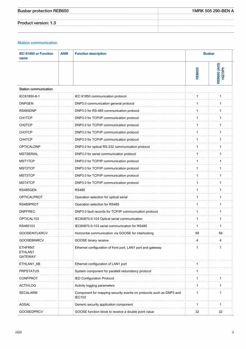
Station communication
IEC 61850 or Functionname
ANSI Function description Busbar
RE
B65
0
RE
B65
0 (A
03)
HiZ
/3P
h
Station communication
IEC61850-8-1 IEC 61850 communication protocol 1 1
DNPGEN DNP3.0 communication general protocol 1 1
RS485DNP DNP3.0 for RS-485 communication protocol 1 1
CH1TCP DNP3.0 for TCP/IP communication protocol 1 1
CH2TCP DNP3.0 for TCP/IP communication protocol 1 1
CH3TCP DNP3.0 for TCP/IP communication protocol 1 1
CH4TCP DNP3.0 for TCP/IP communication protocol 1 1
OPTICALDNP DNP3.0 for optical RS-232 communication protocol 1 1
MSTSERIAL DNP3.0 for serial communication protocol 1 1
MST1TCP DNP3.0 for TCP/IP communication protocol 1 1
MST2TCP DNP3.0 for TCP/IP communication protocol 1 1
MST3TCP DNP3.0 for TCP/IP communication protocol 1 1
MST4TCP DNP3.0 for TCP/IP communication protocol 1 1
RS485GEN RS485 1 1
OPTICALPROT Operation selection for optical serial 1 1
RS485PROT Operation selection for RS485 1 1
DNPFREC DNP3.0 fault records for TCP/IP communication protocol 1 1
OPTICAL103 IEC60870-5-103 Optical serial communication 1 1
RS485103 IEC60870-5-103 serial communication for RS485 1 1
GOOSEINTLKRCV Horizontal communication via GOOSE for interlocking 59 59
GOOSEBINRCV GOOSE binary receive 4 4
ETHFRNTETHLAN1GATEWAY
Ethernet configuration of front port, LAN1 port and gateway 1 1
ETHLAN1_AB Ethernet configuration of LAN1 port 1
PRPSTATUS System component for parallell redundancy protocol 1
CONFPROT IED Configuration Protocol 1 1
ACTIVLOG Activity logging parameters 1 1
SECALARM Component for mapping security events on protocols such as DNP3 andIEC103
1 1
AGSAL Generic security application component 1 1
GOOSEDPRCV GOOSE function block to receive a double point value 32 32
Busbar protection REB650 1MRK 505 290-BEN A
Product version: 1.3
ABB 9

IEC 61850 or Functionname
ANSI Function description Busbar
RE
B65
0
RE
B65
0 (A
03)
HiZ
/3P
h
GOOSEINTRCV GOOSE function block to receive an integer value 32 32
GOOSEMVRCV GOOSE function block to receive a measurand value 16 16
GOOSESPRCV GOOSE function block to receive a single point value 64 64
Basic IED functions
IEC 61850/Functionblock name
Function description
Basic functions included in all products
INTERRSIG Self supervision with internal event list 1
SELFSUPEVLST Self supervision with internal event list 1
TIMESYNCHGEN Time synchronization 1
SNTP Time synchronization 1
DTSBEGIN, DTSEND,TIMEZONE
Time synchronization, daylight saving 1
IRIG-B Time synchronization 1
SETGRPS Setting group handling 1
ACTVGRP Parameter setting groups 1
TESTMODE Test mode functionality 1
CHNGLCK Change lock function 1
PRIMVAL Primary system values 1
SMAI_20_1 -SMAI_20_12
Signal matrix for analog inputs 2
3PHSUM Summation block 3 phase 12
GBASVAL Global base values for settings 6
ATHSTAT Authority status 1
ATHCHCK Authority check 1
AUTHMAN Authority management 1
FTPACCS FTPS access with password 1
DOSFRNT Denial of service, frame rate control for front port 1
DOSLAN1 Denial of service, frame rate control for LAN1A and LAN1B ports 1
DOSSCKT Denial of service, socket flow control 1
Busbar protection REB650 1MRK 505 290-BEN A
Product version: 1.3
10 ABB

4. Differential protection
1Ph High impedance differential protection HZPDIFThe 1Ph High impedance differential protection HZPDIFfunctions can be used when the involved CT cores have thesame turns ratio and similar magnetizing characteristics. Eachutilizes an external summation of the currents in theinterconnected CTs, a series resistor, and a voltagedependent resistor which are mounted externally connectedto the IED.
The external resistor unit shall be ordered under accessories.
Three instances of 1Ph High impedance differential protectionfunction (HZPDIF) can be used to provide a three phasedifferential protection function to be used for example asbusbar protection. One instance of HZPDIF can also be usedas high impedance REF protection.
Separate low level alarm with independent time delay isincluded.
5. Current protection
Four step phase overcurrent protection, 3-phase outputOC4PTOCThe four step phase overcurrent protection functionOC4PTOC has an inverse or definite time delay independentfor step 1 and 4 separately. Step 2 and 3 are always definitetime delayed.
All IEC and ANSI inverse time characteristics are available.
The directional function is voltage polarized with memory. Thefunction can be set to be directional or non-directionalindependently for each of the steps.
Second harmonic blocking level can be set for the functionand can be used to block each step individually
Four step residual overcurrent protection, zero sequence andnegative sequence direction EF4PTOCThe four step residual overcurrent protection, zero or negativesequence direction (EF4PTOC) has a settable inverse ordefinite time delay independent for step 1 and 4 separately.Step 2 and 3 are always definite time delayed.
All IEC and ANSI inverse time characteristics are available.
EF4PTOC can be set directional or non-directionalindependently for each of the steps.
The directional part of the function can be set to operate onfollowing combinations:• Directional current (I3PDir) versus Polarizing voltage
(U3PPol)• Directional current (I3PDir) versus Polarizing current (I3PPol)• Directional current (I3PDir) versus Dual polarizing (UPol
+ZPol x IPol) where ZPol = RPol + jXPol
IDir, UPol and IPol can be independently selected to be eitherzero sequence or negative sequence.
Second harmonic blocking level can be set for the functionand can be used to block each step individually.
Thermal overload protection, two time constant TRPTTRIf a power transformer or generator reaches very hightemperatures the equipment might be damaged. Theinsulation within the transformer/generator will have forcedageing. As a consequence of this the risk of internal phase-to-phase or phase-to-earth faults will increase. High temperaturewill degrade the quality of the transformer/generator insulation.
The thermal overload protection estimates the internal heatcontent of the transformer/generator (temperature)continuously. This estimation is made by using a thermalmodel of the transformer/generator with two time constants,which is based on current measurement.
Two warning levels are available. This enables actions in thepower system to be done before dangerous temperatures arereached. If the temperature continues to increase to the tripvalue, the protection initiates a trip of the protectedtransformer/generator.
Estimated time to trip before operation is presented.
Breaker failure protection CCRBRF, 3-phase activation andoutputCCRBRF can be current based, contact based, or anadaptive combination of these two conditions.
Breaker failure protection, 3-phase activation and output(CCRBRF) ensures fast back-up tripping of surroundingbreakers in case the own breaker fails to open. CCRBRF canbe current based, contact based, or an adaptive combinationof these two conditions.
Current check with extremely short reset time is used ascheck criterion to achieve high security against inadvertentoperation.
Contact check criteria can be used where the fault currentthrough the breaker is small.
Breaker failure protection, 3-phase activation and output(CCRBRF) current criteria can be fulfilled by one or two phasecurrents the residual current, or one phase current plusresidual current. When those currents exceed the userdefined settings, the function is triggered. These conditionsincrease the security of the back-up trip command.
CCRBRF function can be programmed to give a three-phasere-trip of the own breaker to avoid inadvertent tripping ofsurrounding breakers.
Pole discordance protection CCRPLDCircuit breakers and disconnectors can end up with thephases in different positions (close-open), due to electrical or
Busbar protection REB650 1MRK 505 290-BEN A
Product version: 1.3
ABB 11
mechanical failures. An open phase can cause negative andzero sequence currents which cause thermal stress onrotating machines and can cause unwanted operation of zerosequence or negative sequence current functions.
Normally the own breaker is tripped to correct such asituation. If the situation persists the surrounding breakersshould be tripped to clear the unsymmetrical load situation.
The pole discordance function operates based on informationfrom the circuit breaker logic with additional criteria fromphase selective current unsymmetry.
Negative sequence based overcurrent function DNSPTOCNegative sequence based overcurrent function DNSPTOC istypically used as sensitive earth-fault protection of powerlines, where incorrect zero sequence polarization may resultfrom mutual induction between two or more parallel lines.
Additionally, it is applied in applications on cables, where zerosequence impedance depends on the fault current returnpaths, but the cable negative sequence impedance ispractically constant.
The directional function is current and voltage polarized. Thefunction can be set to forward, reverse or non-directionalindependently for each step. Both steps are provided with asettable definite time delay.
DNSPTOC protects against all unbalanced faults includingphase-to-phase faults. The minimum start current of thefunction must be set to above the normal system unbalancelevel in order to avoid unwanted operation.
6. Voltage protection
Two step undervoltage protection UV2PTUVUndervoltages can occur in the power system during faults orabnormal conditions. Two step undervoltage protection(UV2PTUV) function can be used to open circuit breakers toprepare for system restoration at power outages or as long-time delayed back-up to primary protection.
UV2PTUV has two voltage steps, where step 1 is settable asinverse or definite time delayed. Step 2 is always definite timedelayed.
UV2PTUV has a high reset ratio to allow settings close tosystem service voltage.
Two step overvoltage protection OV2PTOVOvervoltages may occur in the power system during abnormalconditions such as sudden power loss, tap changerregulating failures, and open line ends on long lines.
Two step overvoltage protection (OV2PTOV) function can beused to detect open line ends, normally then combined with adirectional reactive over-power function to supervise the
system voltage. When triggered, the function will cause analarm, switch in reactors, or switch out capacitor banks.
OV2PTOV has two voltage steps, where step 1 can be set asinverse or definite time delayed. Step 2 is always definite timedelayed.
OV2PTOV has a high reset ratio to allow settings close tosystem service voltage.
Two step residual overvoltage protection ROV2PTOVResidual voltages may occur in the power system duringearth faults.
Two step residual overvoltage protection ROV2PTOV functioncalculates the residual voltage from the three-phase voltageinput transformers or measures it from a single voltage inputtransformer fed from an open delta or neutral point voltagetransformer.
ROV2PTOV has two voltage steps, where step 1 can be setas inverse or definite time delayed. Step 2 is always definitetime delayed.
7. Secondary system supervision
Fuse failure supervision SDDRFUFThe aim of the fuse failure supervision function SDDRFUF isto block voltage measuring functions at failures in thesecondary circuits between the voltage transformer and theIED in order to avoid inadvertent operations that otherwisemight occur.
The fuse failure supervision function basically has threedifferent detection methods, negative sequence and zerosequence based detection and an additional delta voltageand delta current detection.
The negative sequence detection is recommended for IEDsused in isolated or high-impedance earthed networks. It isbased on the negative-sequence measuring quantities, a highvalue of negative sequence voltage 3U2 without the presence
of the negative-sequence current 3I2.
The zero sequence detection is recommended for IEDs usedin directly or low impedance earthed networks. It is based onthe zero sequence measuring quantities, a high value of zerosequence voltage 3U0 without the presence of the zero
sequence current 3I0.
For better adaptation to system requirements, an operationmode setting has been introduced which makes it possible toselect the operating conditions for negative sequence andzero sequence based function. The selection of differentoperation modes makes it possible to choose differentinteraction possibilities between the negative sequence andzero sequence based detection.
Busbar protection REB650 1MRK 505 290-BEN A
Product version: 1.3
12 ABB

A criterion based on delta current and delta voltagemeasurements can be added to the fuse failure supervisionfunction in order to detect a three phase fuse failure, which inpractice is more associated with voltage transformerswitching during station operations.
Breaker close/trip circuit monitoring TCSSCBRThe trip circuit supervision function TCSSCBR is designed tosupervise the control circuit of the circuit breaker. The tripcircuit supervision generates a current of approximately 1 mAthrough the supervised control circuit. The validity supervisionof a control circuit is provided for power output contacts T1,T2 and T3.
The trip circuit supervision operates after a settable definiteoperating time and resets after a settable definite time whenthe fault disappears.
8. Control
Synchrocheck, energizing check, and synchronizing SESRSYNThe Synchronizing function allows closing of asynchronousnetworks at the correct moment including the breaker closingtime, which improves the network stability.
Synchrocheck, energizing check, and synchronizingSESRSYN function checks that the voltages on both sides ofthe circuit breaker are in synchronism, or with at least oneside dead to ensure that closing can be done safely.
SESRSYN function includes a built-in voltage selectionscheme for double bus and 1½ breaker or ring busbararrangements.
Manual closing as well as automatic reclosing can bechecked by the function and can have different settings.
For systems, which are running asynchronous, asynchronizing function is provided. The main purpose of thesynchronizing function is to provide controlled closing ofcircuit breakers when two asynchronous systems are going tobe connected. The synchronizing function evaluates voltagedifference, phase angle difference, slip frequency andfrequency rate of change before issuing a controlled closingof the circuit breaker. Breaker closing time is a parametersetting.
Apparatus control APCThe apparatus control function APC8 for up to 8 apparatusesis used for control and supervision of circuit breakers,disconnectors and earthing switches within a bay. Permissionto operate is given after evaluation of conditions from otherfunctions such as interlocking, synchrocheck, operator placeselection and external or internal blockings.
Apparatus control features:
• Select-Execute principle to give high reliability• Selection function to prevent simultaneous operation• Selection and supervision of operator place• Command supervision• Block/deblock of operation• Block/deblock of updating of position indications• Substitution of position indications• Overriding of interlocking functions• Overriding of synchrocheck• Operation counter• Suppression of Mid position
Two types of command models can be used:• Direct with normal security• SBO (Select-Before-Operate) with enhanced security
Direct commands are received with no prior select command.SBO commands are received with a select command first andon successful selection, a proceeding operate command.
In normal security, the command is processed and theresulting position is not supervised. However with enhancedsecurity, the command is processed and the resultingposition is supervised.
Control operation can be performed from the local HMI underauthority control if so defined.
IEC09000668-1-en.vsd
IEC09000668 V1 EN
Figure 2. Select before operation with confirmation of command
Busbar protection REB650 1MRK 505 290-BEN A
Product version: 1.3
ABB 13

IEC09000669-2-en.vsd
CancelOk
IEC09000669 V2 EN
Figure 3. Overriding of synchrocheck
The switch controller SCSWI initializes and supervises allfunctions to properly select and operate switching primaryapparatuses. Each of the 8 switch controllers SCSWI mayhandle and operate on one three-phase apparatus.
Each of the 3 circuit breaker controllers SXCBR provides theactual position status and pass the commands to the primarycircuit breaker and supervises the switching operation andpositions.
Each of the 7 circuit switch controllers SXSWI provides theactual position status and pass the commands to the primarydisconnectors and earthing switches and supervises theswitching operation and positions.
InterlockingThe interlocking functionality blocks the possibility to operatehigh-voltage switching devices, for instance when adisconnector is under load, in order to prevent materialdamage and/or accidental human injury.
Each control IED has interlocking functions for differentswitchyard arrangements, each handling the interlocking ofone bay. The interlocking functionality in each IED is notdependent on any central function. For the station-wideinterlocking, the IEDs communicate via the station bus or byusing hard wired binary inputs/outputs.
The interlocking conditions depend on the primary busconfiguration and status of any breaker or switch at any giventime.
Bay control QCBAYThe Bay control QCBAY function is used together with Localremote and local remote control functions to handle theselection of the operator place per bay. QCBAY also providesblocking functions that can be distributed to differentapparatuses within the bay.
Local remote LOCREM /Local remote control LOCREMCTRLThe signals from the local HMI or from an external local/remote switch are applied via the function blocks LOCREM
and LOCREMCTRL to the Bay control QCBAY function block.A parameter in function block LOCREM is set to choose if theswitch signals are coming from the local HMI or from anexternal hardware switch connected via binary inputs.
Circuit breaker control for circuit breaker, CBC3The CBC3 consists of 3 functions:
• SCILO - The Logical node for interlocking. SCILOfunction contains the logic to enable a switchingoperation, and provides the information to SCSWIwether it is permitted to operate due to actualswitchyard topology. The interlocking conditions aregenerated in separate function blocks containing theinterlocking logic.
• SCSWI - The Switch controller initializes and supervisesall functions to properly select and operate switchingprimary apparatuses. The Switch controller may handleand operate on one three-phase device.
• SXCBR - The circuit breaker controller SXCBR providesthe actual position status and pass the commands to theprimary circuit breaker and supervises the switchingoperation and positions.
Logic rotating switch for function selection and LHMIpresentation SLGGIOThe logic rotating switch for function selection and LHMIpresentation SLGGIO (or the selector switch function block) isused to get an enhanced selector switch functionalitycompared to the one provided by a hardware selector switch.Hardware selector switches are used extensively by utilities,in order to have different functions operating on pre-setvalues. Hardware switches are however sources formaintenance issues, lower system reliability and an extendedpurchase portfolio. The logic selector switches eliminate allthese problems.
Selector mini switch VSGGIOThe Selector mini switch VSGGIO function block is amultipurpose function used for a variety of applications, as ageneral purpose switch.
VSGGIO can be controlled from the menu or from a symbolon the single line diagram (SLD) on the local HMI.
IEC 61850 generic communication I/O functions DPGGIOThe IEC 61850 generic communication I/O functions DPGGIOfunction block is used to send double indications to othersystems or equipment in the substation using IEC61850. It isespecially used in the interlocking and reservation station-wide logics.
Single point generic control 8 signals SPC8GGIOThe Single point generic control 8 signals SPC8GGIO functionblock is a collection of 8 single point commands, designed tobring in commands from REMOTE (SCADA) to those parts ofthe logic configuration that do not need extensive commandreceiving functionality (for example, SCSWI). In this way,
Busbar protection REB650 1MRK 505 290-BEN A
Product version: 1.3
14 ABB

simple commands can be sent directly to the IED outputs,without confirmation. The commands can be pulsed or steadywith a settable pulse time.
AutomationBits AUTOBITSThe Automation bits function AUTOBITS is used to configurethe DNP3 protocol command handling. Each of the 3AUTOBITS available has 32 individual outputs available, eachcan be mapped as a binary output point in DNP3.
Function commands for IEC60870-5-103, I103CMD,I103IEDCMD, I103URSCMD, I103GENCMD, I103POSCMDIEC60870–5–103 function and command logic blocks areavailable for configuration of the IED. The output signals arepredefined or user defined depending on selected functionblock.
9. Logic
Tripping logic common 3-phase output SMPPTRCA function block for protection tripping is provided for eachcircuit breaker involved in the tripping of the fault. It providesa settable pulse prolongation to ensure a three-phase trippulse of sufficient length, as well as all functionality necessaryfor correct co-operation with autoreclosing functions.
The trip function block also includes a settable latchfunctionality for breaker lock-out.
Trip matrix logic TMAGGIOThe 12 Trip matrix logic TMAGGIO function each with 32inputs are used to route trip signals and other logical outputsignals to the tripping logics SMPPTRC and SPTPTRC or todifferent output contacts on the IED.
TMAGGIO 3 output signals and the physical outputs allowsthe user to adapt the signals to the physical tripping outputsaccording to the specific application needs for settable pulseor steady output.
Configurable logic blocksA number of logic blocks and timers are available for the userto adapt the configuration to the specific application needs.
• OR function block. Each block has 6 inputs and twooutputs where one is inverted.
• INVERTER function blocks that inverts the input signal.
• PULSETIMER function block can be used, for example, forpulse extensions or limiting of operation of outputs, settablepulse time.
• GATE function block is used for whether or not a signalshould be able to pass from the input to the output.
• XOR function block. Each block has two outputs where oneis inverted.
• LOOPDELAY function block used to delay the output signalone execution cycle.
• TIMERSET function has pick-up and drop-out delayedoutputs related to the input signal. The timer has a settabletime delay and must be On for the input signal to activatethe output with the appropriate time delay.
• AND function block. Each block has four inputs and twooutputs where one is inverted
• SRMEMORY function block is a flip-flop that can set orreset an output from two inputs respectively. Each blockhas two outputs where one is inverted. The memory settingcontrols if the block's output should reset or return to thestate it was, after a power interruption. The SET input haspriority if both SET and RESET inputs are operatedsimultaneously.
• RSMEMORY function block is a flip-flop that can reset orset an output from two inputs respectively. Each block hastwo outputs where one is inverted. The memory settingcontrols if the block's output should reset or return to thestate it was, after a power interruption. The RESET inputhas priority if both SET and RESET are operatedsimultaneously.
Configurable logic Q/TA number of logic blocks and timers, with the capability topropagate timestamp and quality of the input signals, areavailable. The function blocks assist the user to adapt theIEDs configuration to the specific application needs.
• ORQT OR function block that also propagates timestampand quality of input signals. Each block has six inputs andtwo outputs where one is inverted.
• INVERTERQT function block that inverts the input signaland propagates timestamp and quality of input signal.
• PULSETIMERQT Pulse timer function block can be used,for example, for pulse extensions or limiting of operation ofoutputs. The function also propagates timestamp andquality of input signal.
• XORQT XOR function block. The function also propagatestimestamp and quality of input signals. Each block has twooutputs where one is inverted.
• TIMERSETQT function has pick-up and drop-out delayedoutputs related to the input signal. The timer has a settabletime delay. The function also propagates timestamp andquality of input signal.
• ANDQT AND function block. The function also propagatestimestamp and quality of input signals. Each block has fourinputs and two outputs where one is inverted.
Busbar protection REB650 1MRK 505 290-BEN A
Product version: 1.3
ABB 15
• SRMEMORYQT function block is a flip-flop that can set orreset an output from two inputs respectively. Each blockhas two outputs where one is inverted. The memory settingcontrols if the block after a power interruption should returnto the state before the interruption, or be reset. Thefunction also propagates timestamp and quality of inputsignal.
• RSMEMORYQT function block is a flip-flop that can reset orset an output from two inputs respectively. Each block hastwo outputs where one is inverted. The memory settingcontrols if the block after a power interruption should returnto the state before the interruption, or be reset. Thefunction also propagates timestamp and quality of inputsignal.
• INVALIDQT function which sets quality invalid of outputsaccording to a "valid" input. Inputs are copied to outputs. Ifinput VALID is 0, or if its quality invalid bit is set, all outputsinvalid quality bit will be set to invalid. The timestamp of anoutput will be set to the latest timestamp of INPUT andVALID inputs.
• INDCOMBSPQT combines single input signals to groupsignal. Single position input is copied to value part ofSP_OUT output. TIME input is copied to time part ofSP_OUT output. Quality input bits are copied to thecorresponding quality part of SP_OUT output.
• INDEXTSPQT extracts individual signals from a groupsignal input. Value part of single position input is copied toSI_OUT output. Time part of single position input is copiedto TIME output. Quality bits in common part and indicationpart of inputs signal is copied to the corresponding qualityoutput.
Fixed signal function blockThe Fixed signals function FXDSIGN generates nine pre-set(fixed) signals that can be used in the configuration of an IED,either for forcing the unused inputs in other function blocks toa certain level/value, or for creating certain logic. Boolean,integer, floating point, string types of signals are available.
Boolean 16 to Integer conversion B16IBoolean 16 to integer conversion function B16I is used totransform a set of 16 binary (logical) signals into an integer.
Boolean 16 to Integer conversion with logic noderepresentation B16IFCVIBoolean 16 to integer conversion with logic noderepresentation function B16IFCVI is used to transform a set of16 binary (logical) signals into an integer. The block input willfreeze the output at the last value.
Integer to Boolean 16 conversion IB16AInteger to boolean 16 conversion function IB16A is used totransform an integer into a set of 16 binary (logical) signals.
Integer to Boolean 16 conversion with logic noderepresentation IB16FCVBInteger to boolean conversion with logic node representationfunction IB16FCVB is used to transform an integer to 16binary (logic) signals.
IB16FCVB function can receive remote values over IEC61850when the operator position input PSTO is in position remote.The block input will freeze the output at the last value.
Elapsed time integrator with limit transgression and overflowsupervision TEIGGIOThe function TEIGGIO is used for user defined logics and itcan also be used for different purposes internally in the IED .An application example is the integration of elapsed timeduring the measurement of neutral point voltage or neutralcurrent at earth fault conditions.
Settable time limits for warning and alarm are provided. Thetime limit for overflow indication is fixed.
10. Monitoring
IEC61850 generic communication I/O function SPGGIOIEC61850 generic communication I/O functions SPGGIO isused to send one single logical signal to other systems orequipment in the substation.
IEC61850 generic communication I/O function 16 inputsSP16GGIOIEC 61850 generic communication I/O functions 16 inputsSP16GGIO function is used to send up to 16 logical signals toother systems or equipment in the substation.
Measurements CVMMXN, CMMXU, VNMMXU, VMMXU,CMSQI, VMSQIThe measurement functions are used to get on-lineinformation from the IED. These service values make itpossible to display on-line information on the local HMI andon the Substation automation system about:
• measured voltages, currents, frequency, active, reactiveand apparent power and power factor
• primary and secondary phasors• current sequence components• voltage sequence components
Event counter CNTGGIOEvent counter CNTGGIO has six counters which are used forstoring the number of times each counter input has beenactivated.
Event counter with limit supervison L4UFCNTThe 12 Up limit counter L4UFCNT provides a settable counterwith four independent limits where the number of positive and/or negative flanks on the input signal are counted against the
Busbar protection REB650 1MRK 505 290-BEN A
Product version: 1.3
16 ABB

setting values for limits. The output for each limit is activatedwhen the counted value reaches that limit.
Overflow indication is included for each up-counter.
Disturbance report DRPRDREComplete and reliable information about disturbances in theprimary and/or in the secondary system together withcontinuous event-logging is accomplished by the disturbancereport functionality.
Disturbance report DRPRDRE, always included in the IED,acquires sampled data of all selected analog input and binarysignals connected to the function block with a, maximum of40 analog and 96 binary signals.
The Disturbance report functionality is a common name forseveral functions:
• Event list• Indications• Event recorder• Trip value recorder• Disturbance recorder
The Disturbance report function is characterized by greatflexibility regarding configuration, starting conditions,recording times, and large storage capacity.
A disturbance is defined as an activation of an input to theAnRADR or BnRBDR function blocks, which are set to triggerthe disturbance recorder. All connected signals from start ofpre-fault time to the end of post-fault time will be included inthe recording.
Every disturbance report recording is saved in the IED in thestandard Comtrade format as a reader file HDR, aconfiguration file CFG, and a data file DAT. The same appliesto all events, which are continuously saved in a ring-buffer.The local HMI is used to get information about the recordings.The disturbance report files may be uploaded to PCM600 forfurther analysis using the disturbance handling tool.
Event list DRPRDREContinuous event-logging is useful for monitoring the systemfrom an overview perspective and is a complement to specificdisturbance recorder functions.
The event list logs all binary input signals connected to theDisturbance recorder function. The list may contain up to1000 time-tagged events stored in a ring-buffer.
Indications DRPRDRETo get fast, condensed and reliable information aboutdisturbances in the primary and/or in the secondary system itis important to know, for example binary signals that havechanged status during a disturbance. This information is usedin the short perspective to get information via the local HMI ina straightforward way.
There are three LEDs on the local HMI (green, yellow andred), which will display status information about the IED andthe Disturbance recorder function (triggered).
The Indication list function shows all selected binary inputsignals connected to the Disturbance recorder function thathave changed status during a disturbance.
Event recorder DRPRDREQuick, complete and reliable information about disturbancesin the primary and/or in the secondary system is vital, forexample, time-tagged events logged during disturbances.This information is used for different purposes in the shortterm (for example corrective actions) and in the long term (forexample functional analysis).
The event recorder logs all selected binary input signalsconnected to the Disturbance recorder function. Eachrecording can contain up to 150 time-tagged events.
The event recorder information is available for thedisturbances locally in the IED.
The event recording information is an integrated part of thedisturbance record (Comtrade file).
Trip value recorder DRPRDREInformation about the pre-fault and fault values for currentsand voltages are vital for the disturbance evaluation.
The Trip value recorder calculates the values of all selectedanalog input signals connected to the Disturbance recorderfunction. The result is magnitude and phase angle before andduring the fault for each analog input signal.
The trip value recorder information is available for thedisturbances locally in the IED.
The trip value recorder information is an integrated part of thedisturbance record (Comtrade file).
Disturbance recorder DRPRDREThe Disturbance recorder function supplies fast, completeand reliable information about disturbances in the powersystem. It facilitates understanding system behavior andrelated primary and secondary equipment during and after adisturbance. Recorded information is used for differentpurposes in the short perspective (for example correctiveactions) and long perspective (for example functional analysis).
The Disturbance recorder acquires sampled data fromselected analog- and binary signals connected to theDisturbance recorder function (maximum 40 analog and 96binary signals). The binary signals available are the same asfor the event recorder function.
The function is characterized by great flexibility and is notdependent on the operation of protection functions. It canrecord disturbances not detected by protection functions. Up
Busbar protection REB650 1MRK 505 290-BEN A
Product version: 1.3
ABB 17

to 9,9 seconds of data before the trigger instant can besaved in the disturbance file.
The disturbance recorder information for up to 100disturbances are saved in the IED and the local HMI is usedto view the list of recordings.
Measured value expander block MVEXPThe current and voltage measurements functions (CVMMXN,CMMXU, VMMXU and VNMMXU), current and voltagesequence measurement functions (CMSQI and VMSQI) andIEC 61850 generic communication I/O functions (MVGGIO)are provided with measurement supervision functionality. Allmeasured values can be supervised with four settable limits:low-low limit, low limit, high limit and high-high limit. Themeasure value expander block MVEXP has been introducedto enable translating the integer output signal from themeasuring functions to 5 binary signals: below low-low limit,below low limit, normal, above high limit or above high-highlimit. The output signals can be used as conditions in theconfigurable logic or for alarming purpose.
Station battery supervision SPVNZBATThe station battery supervision function SPVNZBAT is usedfor monitoring battery terminal voltage.
SPVNZBAT activates the start and alarm outputs when thebattery terminal voltage exceeds the set upper limit or dropsbelow the set lower limit. A time delay for the overvoltage andundervoltage alarms can be set according to definite timecharacteristics.
SPVNZBAT operates after a settable operate time and resetswhen the battery undervoltage or overvoltage conditiondisappears after settable reset time.
Insulation gas monitoring function SSIMGInsulation gas monitoring function SSIMG is used formonitoring the circuit breaker condition. Binary informationbased on the gas pressure in the circuit breaker is used asinput signals to the function. In addition, the functiongenerates alarms based on received information.
Insulation liquid monitoring function SSIMLInsulation liquid monitoring function SSIML is used formonitoring the circuit breaker condition. Binary informationbased on the oil level in the circuit breaker is used as inputsignals to the function. In addition, the function generatesalarms based on received information.
Circuit breaker monitoring SSCBRThe circuit breaker condition monitoring function SSCBR isused to monitor different parameters of the circuit breaker.The breaker requires maintenance when the number ofoperations has reached a predefined value. The energy is
calculated from the measured input currents as a sum of Iytvalues. Alarms are generated when the calculated valuesexceed the threshold settings.
The function contains a block alarm functionality.
The supervised and presented breaker functions include• breaker open and close travel time• spring charging time• number of breaker operations• accumulated IYt per phase with alarm and lockout• remaining breaker life per phase• breaker inactivity
11. Metering
Pulse counter logic PCGGIOPulse counter (PCGGIO) function counts externally generatedbinary pulses, for instance pulses coming from an externalenergy meter, for calculation of energy consumption values.The pulses are captured by the BIO (binary input/output)module and then read by the PCGGIO function. A scaledservice value is available over the station bus.
Function for energy calculation and demand handlingETPMMTROutputs from the Measurements (CVMMXN) function can beused to calculate energy consumption. Active as well asreactive values are calculated in import and export direction.Values can be read or generated as pulses. Maximumdemand power values are also calculated by the function.
12. Human Machine interface
Local HMI
IEC12000175 V1 EN
Figure 4. Local human-machine interface
The LHMI of the IED contains the following elements:• Display (LCD)• Buttons• LED indicators• Communication port for PCM600
The LHMI is used for setting, monitoring and controlling.
The Local human machine interface, LHMI includes agraphical monochrome LCD with a resolution of 320x240pixels. The character size may vary depending on selectedlanguage. The amount of characters and rows fitting the viewdepends on the character size and the view that is shown.
Busbar protection REB650 1MRK 505 290-BEN A
Product version: 1.3
18 ABB

The LHMI is simple and easy to understand. The whole frontplate is divided into zones, each with a well-definedfunctionality:
• Status indication LEDs• Alarm indication LEDs which can indicate three states
with the colors green, yellow and red, with user definedand also printable label. All LEDs are configurable fromthe PCM600 tool
• Liquid crystal display (LCD)• Keypad with push buttons for control and navigation
purposes, switch for selection between local and remotecontrol and reset
• Five user programmable function buttons• An isolated RJ45 communication port for PCM600
13. Basic IED functions
Self supervision with internal event listThe Self supervision with internal event list INTERRSIG andSELFSUPEVLST function reacts to internal system eventsgenerated by the different built-in self-supervision elements.The internal events are saved in an internal event listpresented on the LHMI and in PCM600 event viewer tool.
Time synchronizationUse a common global source for example GPS timesynchronization inside each substation as well as inside thearea of the utility responsibility to achieve a common timebase for the IEDs in a protection and control system. Thismakes comparison and analysis of events and disturbancedata between all IEDs in the power system possible.
Time-tagging of internal events and disturbances are anexcellent help when evaluating faults. Without timesynchronization, only the events within the IED can becompared to one another. With time synchronization, eventsand disturbances within the entire station, and even betweenline ends, can be compared during evaluation.
In the IED, the internal time can be synchronized from anumber of sources:
• SNTP• IRIG-B• DNP• IEC60870-5-103
Parameter setting groups ACTVGRPUse the four different groups of settings to optimize the IEDoperation for different power system conditions. Creating andswitching between fine-tuned setting sets, either from thelocal HMI or configurable binary inputs, results in a highlyadaptable IED that can be applied to a variety of powersystem scenarios.
Test mode functionality TESTMODEThe protection and control IEDs may have many includedfunctions. To make the testing procedure easier, the IEDsinclude the feature that allows individual blocking of allfunctions except the function(s) the shall be tested.
There are two ways of entering the test mode:
• By configuration, activating an input signal of thefunction block TESTMODE
• By setting the IED in test mode in the local HMI
While the IED is in test mode, all protection functions areblocked.
Any function can be unblocked individually regardingfunctionality and event signaling. This enables the user tofollow the operation of one or several related functions tocheck functionality and to check parts of the configuration,and so on.
Forcing of binary outputs, wether from the LHMI or from thePCM600 is only possible when the IED is in test mode.
Change lock function CHNGLCKChange lock function CHNGLCK is used to block furtherchanges to the IED configuration and settings once thecommissioning is complete. The purpose is to blockinadvertent IED configuration changes beyond a certain pointin time.
The change lock function activation is normally connected toa binary input.
AuthorizationThe user categories and roles with user rights as defined byIEC 62359–8 for role based access control are pre-defined inthe IED.
The IED users can be created, deleted and edited only withPCM600.
Password policies are set in the PCM600 IED usermanagement tool.
At delivery, the IED user has full access as SuperUser untilusers are created with PCM600.
Authority status ATHSTATAuthority status ATHSTAT function is an indication functionblock for user log-on activity.
User denied attempt to log-on and user successful log-on arereported.
Authority check ATHCHCKTo safeguard the interests of our customers, both the IEDand the tools that are accessing the IED are protected, bymeans of authorization handling. The authorization handling
Busbar protection REB650 1MRK 505 290-BEN A
Product version: 1.3
ABB 19

of the IED and the PCM600 is implemented at both accesspoints to the IED:
• local, through the local HMI• remote, through the communication ports
The IED users can be created, deleted and edited only withPCM600 IED user management tool.
IEC12000202-1-en.vsd
IEC12000202 V1 EN
Figure 5. PCM600 user management tool
AUTHMANThis function enables/disables the maintenance menu. It alsocontrols the maintenance menu log on time out.
FTP access with SSL FTPACCSThe FTP Client defaults to the best possible security modewhen trying to negotiate with SSL.
The automatic negotiation mode acts on port number andserver features. It tries to immediately activate implicit SSL ifthe specified port is 990. If the specified port is any other, ittries to negotiate with explicit SSL via AUTH SSL/TLS.
Using FTP without SSL encryption gives the FTP clientreduced capabilities. This mode is only for accessingdisturbance recorder data from the IED.
If normal FTP is required to read outdisturbance recordings, create a specificaccount for this purpose with rights only todo File transfer. The password of this userwill be exposed in clear text on the wire.
Generic security application AGSALAs a logical node AGSAL is used for monitoring securityviolation regarding authorization, access control and inactive
association including authorization failure. Therefore, all theinformation in AGSAL can be configured to report to 61850client.
Activity logging ACTIVLOGACTIVLOG contains all settings for activity logging.
There can be 6 external log servers to send syslog events to.Each server can be configured with IP address; IP portnumber and protocol format. The format can be either syslog(RFC 5424) or Common Event Format (CEF) from ArcSight.
Security alarm SECALARMThe function creates and distributes security events formapping the security events on protocols such as DNP3.
It is possible to map respective protocol to the signals ofinterest and configure them for monitoring with theCommunication Management tool (CMT) in PCM600. Noevents are mapped by default.
Parameter names:• EVENTID: Event ID of the generated security event• SEQNUMBER: Sequence number of the generated security
event
Security eventsAll user operations are logged as events. These events canbe sent to external security log servers using SYSLOG dataformats. The log servers can be configured using PCM600.
14. Station communication
IEC 61850-8-1 communication protocolThe IED supports the communication protocols IEC61850-8-1 and DNP3 over TCP/IP. All operational informationand controls are available through these protocols. However,some communication functions, for example, horizontalcommunication (GOOSE) between the IEDs, is only enabledby the IEC 61850-8-1 communication protocol.
The IED is equipped with optical Ethernet rear port(s) for thesubstation communication standard IEC 61850-8-1. IEC61850-8-1 protocol allows intelligent electrical devices (IEDs)from different vendors to exchange information and simplifiessystem engineering. Peer-to-peer communication accordingto GOOSE is part of the standard. Disturbance files uploadingis provided.
Disturbance files are accessed using the IEC 61850-8-1protocol. Disturbance files are also available to any Ethernetbased application via FTP in the standard Comtrade format.Further, the IED can send and receive binary values, doublepoint values and measured values (for example from MMXUfunctions), together with their quality bit, using the IEC61850-8-1 GOOSE profile. The IED meets the GOOSEperformance requirements for tripping applications insubstations, as defined by the IEC 61850 standard. The IED
Busbar protection REB650 1MRK 505 290-BEN A
Product version: 1.3
20 ABB

interoperates with other IEC 61850-compliant IEDs, andsystems and simultaneously reports events to five differentclients on the IEC 61850 station bus.
The Denial of Service functions DOSLAN1 and DOSFRNT areincluded to limit the inbound network traffic. Thecommunication can thus never compromise the primaryfunctionality of the IED.
The event system has a rate limiter to reduce CPU load. Theevent channel has a quota of 10 events/second after theinitial 30 events/second. If the quota is exceeded the eventchannel transmission is blocked until the event changes isbelow the quota, no event is lost.
All communication connectors, except for the front portconnector, are placed on integrated communication modules.The IED is connected to Ethernet-based communicationsystems via the fibre-optic multimode LC connector(s)(100BASE-FX).
The IED supports SNTP and IRIG-B time synchronizationmethods with a time-stamping accuracy of ±1 ms.
• Ethernet based: SNTP and DNP3• With time synchronization wiring: IRIG-B
The IED supports IEC 60870-5-103 time synchronizationmethods with a time stamping accuracy of ±5 ms.
Table 1. Supported station communication interfaces and protocols
Protocol Ethernet Serial
100BASE-FX LC Glass fibre (ST connector) EIA-485
IEC 61850–8–1 ● - -
DNP3 ● ● ●
IEC 60870-5-103 - ● ●● = Supported
Horizontal communication via GOOSE for interlockingGOOSE communication can be used for exchanginginformation between IEDs via the IEC 61850-8-1 stationcommunication bus. This is typically used for sendingapparatus position indications for interlocking or reservationsignals for 1-of-n control. GOOSE can also be used toexchange any boolean, integer, double point and analogmeasured values between IEDs.
DNP3 protocolDNP3 (Distributed Network Protocol) is a set ofcommunications protocols used to communicate databetween components in process automation systems. For adetailed description of the DNP3 protocol, see the DNP3Communication protocol manual.
IEC 60870-5-103 communication protocolIEC 60870-5-103 is an unbalanced (master-slave) protocol forcoded-bit serial communication exchanging information with acontrol system, and with a data transfer rate up to 19200 bit/s. In IEC terminology, a primary station is a master and asecondary station is a slave. The communication is based ona point-to-point principle. The master must have softwarethat can interpret IEC 60870-5-103 communication messages.
IEC 60870-5-103 protocol can be configured to use eitherthe optical serial or RS485 serial communication interface on
the COM03 or the COM05 communication module. Thefunctions Operation selection for optical serial OPTICALPROTand Operation selection for RS485 RS485PROT are used toselect the communication interface.
The function IEC60870-5-103 Optical serial communication,OPTICAL103, is used to configure the communicationparameters for the optical serial communication interface. Thefunction IEC60870-5-103 serial communication for RS485,RS485103, is used to configure the communicationparameters for the RS485 serial communication interface.
IEC 62439-3 Parallel Redundancy ProtocolRedundant station bus communication according to IEC62439-3 Edition 2 is available as option in the Customized650 Ver 1.3 series IEDs, and the selection is made atordering. Redundant station bus communication according toIEC 62439-3 Edition 2 uses both ports LAN1A and LAN1B onthe COM03 module.
Select COM03 for redundant station busaccording to IEC 62439-3 Edition 2protocol, at the time of ordering.IEC 62439-3 Edition 2 is NOT compatiblewith IEC 62439-3 Edition 1.
Busbar protection REB650 1MRK 505 290-BEN A
Product version: 1.3
ABB 21

15. Hardware description
Layout and dimensionsMounting alternatives
• 19” rack mounting kit
See ordering for details about available mounting alternatives.
Rack mounting a single 3U IED
B
A C
D
IEC11000248 V1 EN
Figure 6. Rack mounted 3U IED
A 224 mm + 12 mm with ring-lug connectors
B 22.5 mm
C 482 mm
D 132 mm, 3U
Busbar protection REB650 1MRK 505 290-BEN A
Product version: 1.3
22 ABB

16. Connection diagrams
Connection diagramsThe connection diagrams are delivered on the IEDConnectivity package DVD as part of the product delivery.
The latest versions of the connection diagrams can bedownloaded from http://www.abb.com/substationautomation.
Connection diagrams for Customized products
Connection diagram, 650 series 1.3 1MRK006501-AD
Connection diagrams for Configured products
Connection diagram, REB650 1.3, (HiZ/3Ph) A031MRK006501-MD
Busbar protection REB650 1MRK 505 290-BEN A
Product version: 1.3
ABB 23

17. Technical data
General
Definitions
Reference value The specified value of an influencing factor to which are referred the characteristics of the equipment
Nominal range The range of values of an influencing quantity (factor) within which, under specified conditions, the equipment meets thespecified requirements
Operative range The range of values of a given energizing quantity for which the equipment, under specified conditions, is able to perform itsintended functions according to the specified requirements
Energizing quantities, rated values and limitsAnalog inputs
Table 2. Energizing inputs
Description Value
Rated frequency 50/60 Hz
Operating range Rated frequency ± 5 Hz
Current inputs Rated current, In 0.1/0.5 A1) 1/5 A2)
Thermal withstand capability:
• Continuously 4 A 20 A
• For 1 s 100 A 500 A *)
• For 10 s 20 A 100 A
Dynamic current withstand:
• Half-wave value 250 A 1250 A
Input impedance <100 mΩ <20 mΩ
Voltage inputs Rated voltage, Un 100 V AC/ 110 V AC/ 115 V AC/ 120 V AC
Voltage withstand:
• Continuous 420 V rms
• For 10 s 450 V rms
Burden at rated voltage <0.05 VA
*) max. 350 A for 1 s when COMBITEST test switch is included.
1) Residual current2) Phase currents or residual current
Busbar protection REB650 1MRK 505 290-BEN A
Product version: 1.3
24 ABB

Auxiliary AC and DC voltage
Table 3. Power supply
Description PSM01 PSM02 PSM03
Uauxnominal 24, 30V DC 48, 60, 110, 125 V DC 100, 110, 120, 220, 240 V AC, 50and 60 Hz
110, 125, 220, 250 V DC
Uauxvariation 80...120% of Un (19.2...36 V DC) 80...120% of Un (38.4...150 V DC) 85...110% of Un (85...264 V AC)
80...120% of Un (88...300 V DC)
Maximum load of auxiliary voltagesupply
35 W for DC40 VA for AC
Ripple in the DC auxiliary voltage Max 15% of the DC value (at frequency of 100 and 120 Hz)
Maximum interruption time in theauxiliary DC voltage withoutresetting the IED
50 ms at Uaux
Resolution of the voltagemeasurement in PSM module
1 bit represents 0,5 V (+/- 1 VDC) 1 bit represents 1 V (+/- 1 VDC) 1 bit represents 2 V (+/- 1 VDC)
Binary inputs and outputs
Table 4. Binary inputs
Description Value
Operating range Maximum input voltage 300 V DC
Rated voltage 24...250 V DC
Current drain 1.6...1.8 mA
Power consumption/input <0.38 W
Threshold voltage 15...221 V DC (parametrizable in the range in steps of 1% of the ratedvoltage)
Table 5. Signal output and IRF output
IRF relay change over - type signal output relay
Description Value
Rated voltage 250 V AC/DC
Continuous contact carry 5 A
Make and carry for 3.0 s 10 A
Make and carry 0.5 s 30 A
Breaking capacity when the control-circuit time constant L/R<40 ms, atU< 48/110/220 V DC
≤0.5 A/≤0.1 A/≤0.04 A
Busbar protection REB650 1MRK 505 290-BEN A
Product version: 1.3
ABB 25

Table 6. Power output relays without TCS function
Description Value
Rated voltage 250 V AC/DC
Continuous contact carry 8 A
Make and carry for 3.0 s 15 A
Make and carry for 0.5 s 30 A
Breaking capacity when the control-circuit time constant L/R<40 ms, atU< 48/110/220 V DC
≤1 A/≤0.3 A/≤0.1 A
Table 7. Power output relays with TCS function
Description Value
Rated voltage 250 V DC
Continuous contact carry 8 A
Make and carry for 3.0 s 15 A
Make and carry for 0.5 s 30 A
Breaking capacity when the control-circuit time constant L/R<40 ms, atU< 48/110/220 V DC
≤1 A/≤0.3 A/≤0.1 A
Control voltage range 20...250 V DC
Current drain through the supervision circuit ~1.0 mA
Minimum voltage over the TCS contact 20 V DC
Table 8. Ethernet interfaces
Ethernet interface Protocol Cable Data transfer rate
100BASE-TX - CAT 6 S/FTP or better 100 MBits/s
100BASE-FX TCP/IP protocol Fibre-optic cable with LCconnector
100 MBits/s
Table 9. Fibre-optic communication link
Wave length Fibre type Connector Permitted path attenuation1) Distance
1300 nm MM 62.5/125 μmglass fibre core
LC <8 dB 2 km
1) Maximum allowed attenuation caused by connectors and cable together
Table 10. X8/IRIG-B and EIA-485 interface
Type Protocol Cable
Tension clamp connection IRIG-B Shielded twisted pair cableRecommended: CAT 5, Belden RS-485 (9841- 9844) or Alpha Wire(Alpha 6222-6230)
Tension clamp connection IEC 68070–5–103DNP3.0
Shielded twisted pair cableRecommended: DESCAFLEX RD-H(ST)H-2x2x0.22mm2, Belden 9729,Belden 9829
Busbar protection REB650 1MRK 505 290-BEN A
Product version: 1.3
26 ABB

Table 11. IRIG-B
Type Value Accuracy
Input impedance 430 Ohm -
Minimum input voltage HIGH 4.3 V -
Maximum input voltage LOW 0.8 V -
Table 12. EIA-485 interface
Type Value Conditions
Minimum differential driver outputvoltage
1.5 V –
Maximum output current 60 mA -
Minimum differential receiver inputvoltage
0.2 V -
Supported bit rates 300, 600, 1200, 2400, 4800,9600, 19200, 38400, 57600,115200
-
Maximum number of 650 IEDssupported on the same bus
32 -
Max. cable length 925 m (3000 ft) Cable: AWG24 or better, stub lines shall be avoided
Table 13. Serial rear interface
Type Counter connector
Serial port (X9) Optical serial port, type ST for IEC 60870-5-103 and DNP serial
Table 14. Optical serial port (X9)
Wave length Fibre type Connector Permitted path attenuation1)
820 nm MM 62,5/125 µm glass fibrecore
ST 6.8 dB (approx. 1700m length with 4 db / km fibre attenuation)
820 nm MM 50/125 µm glass fibrecore
ST 2.4 dB (approx. 600m length with 4 db / km fibre attenuation)
1) Maximum allowed attenuation caused by fibre
Influencing factors
Ingress protection
Table 15. Ingress protection
Description Value
IED front IP 54
IED rear IP 21
IED sides IP 42
IED top IP 42
IED bottom IP 21
Busbar protection REB650 1MRK 505 290-BEN A
Product version: 1.3
ABB 27
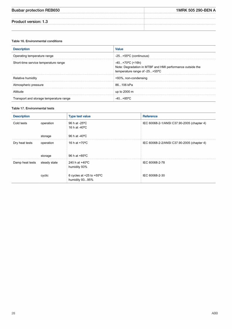
Table 16. Environmental conditions
Description Value
Operating temperature range -25...+55ºC (continuous)
Short-time service temperature range -40...+70ºC (<16h)Note: Degradation in MTBF and HMI performance outside thetemperature range of -25...+55ºC
Relative humidity <93%, non-condensing
Atmospheric pressure 86...106 kPa
Altitude up to 2000 m
Transport and storage temperature range -40...+85ºC
Table 17. Environmental tests
Description Type test value Reference
Cold tests operation storage
96 h at -25ºC16 h at -40ºC 96 h at -40ºC
IEC 60068-2-1/ANSI C37.90-2005 (chapter 4)
Dry heat tests operation storage
16 h at +70ºC 96 h at +85ºC
IEC 60068-2-2/ANSI C37.90-2005 (chapter 4)
Damp heat tests steady state cyclic
240 h at +40ºChumidity 93% 6 cycles at +25 to +55ºChumidity 93...95%
IEC 60068-2-78 IEC 60068-2-30
Busbar protection REB650 1MRK 505 290-BEN A
Product version: 1.3
28 ABB

Type tests according to standards
Table 18. Electromagnetic compatibility tests
Description Type test value Reference
100 kHz and 1 MHz burst disturbance test IEC 61000-4-18, level 3IEC 60255-22-1ANSI C37.90.1-2012
• Common mode 2.5 kV
• Differential mode 2.5 kV
Electrostatic discharge test IEC 61000-4-2, level 4IEC 60255-22-2ANSI C37.90.3-2001
• Contact discharge 8 kV
• Air discharge 15 kV
Radio frequency interference tests
• Conducted, common mode 10 V (emf), f=150 kHz...80 MHz IEC 61000-4-6 , level 3IEC 60255-22-6
• Radiated, amplitude-modulated 20 V/m (rms), f=80...1000 MHz and f=1.4...2.7GHz
IEC 61000-4-3, level 3IEC 60255-22-3ANSI C37.90.2-2004
Fast transient disturbance tests IEC 61000-4-4IEC 60255-22-4, class AANSI C37.90.1-2012
• Communication ports 4 kV
• Other ports 4 kV
Surge immunity test IEC 61000-4-5IEC 60255-22-5
• Communication 1 kV line-to-earth
• Other ports 2 kV line-to-earth, 1 kV line-to-line
• Power supply 4 kV line-to-earth, 2 kV line-to-line
Power frequency (50 Hz) magnetic field IEC 61000-4-8, level 5
• 3 s 1000 A/m
• Continuous 100 A/m
Pulse magnetic field immunity test 1000A/m IEC 61000–4–9, level 5
Damped oscillatory magnetic field 100A/m, 100 kHz and 1MHz IEC 6100–4–10, level 5
Power frequency immunity test IEC 60255-22-7, class AIEC 61000-4-16
• Common mode 300 V rms
• Differential mode 150 V rms
Voltage dips and short interruptionsc on DCpower supply
Dips:40%/200 ms70%/500 msInterruptions:0-50 ms: No restart0...∞ s : Correct behaviour at power down
IEC 60255-11IEC 61000-4-11
Busbar protection REB650 1MRK 505 290-BEN A
Product version: 1.3
ABB 29

Table 18. Electromagnetic compatibility tests, continued
Description Type test value Reference
Voltage dips and interruptions on AC powersupply
Dips:40% 10/12 cycles at 50/60 Hz70% 25/30 cycles at 50/60 HzInterruptions:0–50 ms: No restart0...∞ s: Correct behaviour at power down
IEC 60255–11IEC 61000–4–11
Electromagnetic emission tests EN 55011, class AIEC 60255-25ANSI C63.4, FCC
• Conducted, RF-emission (mains terminal)
0.15...0.50 MHz < 79 dB(µV) quasi peak< 66 dB(µV) average
0.5...30 MHz < 73 dB(µV) quasi peak< 60 dB(µV) average
• Radiated RF-emission, IEC
30...230 MHz < 40 dB(µV/m) quasi peak, measured at 10 mdistance
230...1000 MHz < 47 dB(µV/m) quasi peak, measured at 10 mdistance
Table 19. Insulation tests
Description Type test value Reference
Dielectric tests: IEC 60255-5ANSI C37.90-2005
• Test voltage 2 kV, 50 Hz, 1 min1 kV, 50 Hz, 1 min, communication
Impulse voltage test: IEC 60255-5ANSI C37.90-2005
• Test voltage 5 kV, unipolar impulses, waveform 1.2/50 μs,source energy 0.5 J1 kV, unipolar impulses, waveform 1.2/50 μs,source energy 0.5 J, communication
Insulation resistance measurements IEC 60255-5ANSI C37.90-2005
• Isolation resistance >100 MΏ, 500 V DC
Protective bonding resistance IEC 60255-27
• Resistance <0.1 Ώ (60 s)
Busbar protection REB650 1MRK 505 290-BEN A
Product version: 1.3
30 ABB

Table 20. Mechanical tests
Description Reference Requirement
Vibration response tests (sinusoidal) IEC 60255-21-1 Class 1
Vibration endurance test IEC60255-21-1 Class 1
Shock response test IEC 60255-21-2 Class 1
Shock withstand test IEC 60255-21-2 Class 1
Bump test IEC 60255-21-2 Class 1
Seismic test IEC 60255-21-3 Class 2
Product safety
Table 21. Product safety
Description Reference
LV directive 2006/95/EC
Standard EN 60255-27 (2005)
EMC compliance
Table 22. EMC compliance
Description Reference
EMC directive 2004/108/EC
Standard EN 50263 (2000)EN 60255-26 (2007)
Busbar protection REB650 1MRK 505 290-BEN A
Product version: 1.3
ABB 31

Differential protection
Table 23. 1Ph High impedance differential protection HZPDIF
Function Range or value Accuracy
Operate voltage (20-400) VI=U/R
± 1.0% of Ir
Reset ratio >95% -
Maximum continuous power U>Trip2/SeriesResistor ≤200 W -
Operate time 10 ms typically at 0 to 10 x Ud -
Reset time 100 ms typically at 10 to 0 x Ud -
Critical impulse time 2 ms typically at 0 to 10 x Ud -
Current protection
Table 24. Four step phase overcurrent protection, 3-phase output OC4PTOC
Function Setting range Accuracy
Operate current (5-2500)% of lBase ± 1.0% of Ir at I ≤ Ir± 1.0% of I at I > Ir
Reset ratio > 95% -
Min. operating current (5-10000)% of lBase ± 1.0% of Ir at I ≤ Ir±1.0% of I at I > Ir
2nd harmonic blocking (5–100)% of fundamental ± 2.0% of Ir
Independent time delay (0.000-60.000) s ± 0.5% ±25 ms
Minimum operate time forinverse characteristics
(0.000-60.000) s ± 0.5% ±25 ms
Inverse characteristics, seetable 57, table 58 and table 59
15 curve types 1) ANSI/IEEE C37.112IEC 60255–151±3% or ±40 ms0.10 ≤ k ≤ 3.001.5 x Iset ≤ I ≤ 20 x Iset
Operate time, nondirectionalstart function
25 ms typically at 0 to 2 x Iset -
Reset time, nondirectional startfunction
35 ms typically at 2 to 0 x Iset -
Operate time, directional startfunction
50 ms typically at 0 to 2 x Iset -
Reset time, directional startfunction
35 ms typically at 2 to 0 x Iset -
Critical impulse time 10 ms typically at 0 to 2 x Iset -
Impulse margin time 15 ms typically -
1) Note: Timing accuracy only valid when 2nd harmonic blocking is turned off
Busbar protection REB650 1MRK 505 290-BEN A
Product version: 1.3
32 ABB

Table 25. Four step residual overcurrent protection EF4PTOC
Function Range or value Accuracy
Operate current (1-2500)% of lBase ± 1.0% of Ir at I < Ir± 1.0% of I at I > Ir
Reset ratio > 95% -
Operate current for directionalcomparison, Zero sequence
(1–100)% of lBase ± 2.0% of Ir
Operate current for directionalcomparison, Negative sequence
(1–100)% of lBase ± 2.0% of Ir
Min. operating current (1-10000)% of lBase ± 1.0% of Ir at I < Ir± 1.0% of I at I >Ir
Minimum operate time forinverse characteristics
(0.000-60.000) s ± 0.5% ± 25 ms
Timers (0.000-60.000) s ± 0.5% ±25 ms
Inverse characteristics, see table57, table 58 and table 59
15 curve types 1) ANSI/IEEE C37.112IEC 60255–151±3% or ±40 ms0.10 ≤ k ≤ 3.001.5 x Iset ≤ I ≤ 20 x Iset
Minimum polarizing voltage, Zerosequence
(1–100)% of UBase ± 0.5% of Ur
Minimum polarizing voltage,Negative sequence
(1–100)% of UBase ± 0.5% of Ur
Minimum polarizing current, Zerosequence
(2–100)% of IBase ±1.0% of Ir
Minimum polarizing current,Negative sequence
(2–100)% of IBase ±1.0% of Ir
Real part of source Z used forcurrent polarization
(0.50-1000.00) W/phase -
Imaginary part of source Z usedfor current polarization
(0.50–3000.00) W/phase -
Operate time, non-directionalstart function
30 ms typically at 0.5 to 2 x Iset -
Reset time, non-directional startfunction
30 ms typically at 2 to 0.5 x Iset -
Operate time, directional startfunction
30 ms typically at 0,5 to 2 x IN -
Reset time, directional startfunction
30 ms typically at 2 to 0,5 x IN -
1) Note: Timing accuracy only valid when 2nd harmonic blocking is turned off.
Busbar protection REB650 1MRK 505 290-BEN A
Product version: 1.3
ABB 33
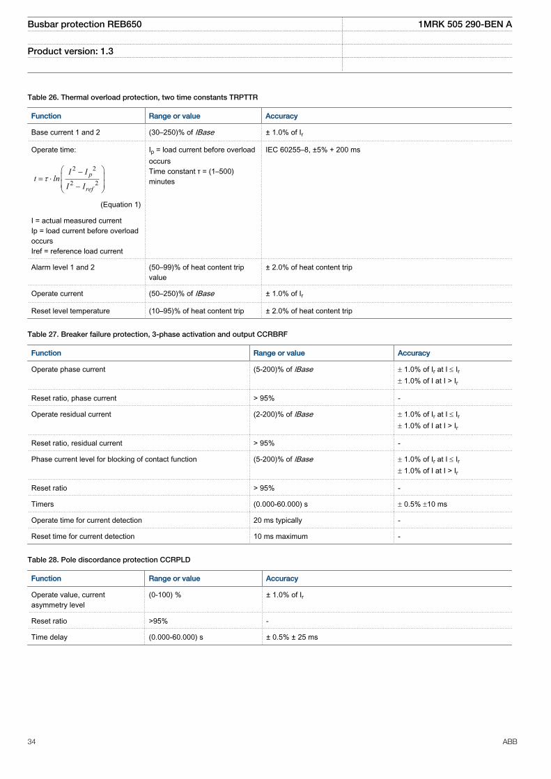
Table 26. Thermal overload protection, two time constants TRPTTR
Function Range or value Accuracy
Base current 1 and 2 (30–250)% of IBase ± 1.0% of Ir
Operate time:
2 2
2 2p
ref
I It ln
I It
æ ö-ç ÷= ×ç ÷-è ø
EQUATION1356 V2 EN (Equation 1)
I = actual measured currentIp = load current before overloadoccursIref = reference load current
Ip = load current before overloadoccursTime constant τ = (1–500)minutes
IEC 60255–8, ±5% + 200 ms
Alarm level 1 and 2 (50–99)% of heat content tripvalue
± 2.0% of heat content trip
Operate current (50–250)% of IBase ± 1.0% of Ir
Reset level temperature (10–95)% of heat content trip ± 2.0% of heat content trip
Table 27. Breaker failure protection, 3-phase activation and output CCRBRF
Function Range or value Accuracy
Operate phase current (5-200)% of lBase ± 1.0% of Ir at I £ Ir± 1.0% of I at I > Ir
Reset ratio, phase current > 95% -
Operate residual current (2-200)% of lBase ± 1.0% of Ir at I £ Ir± 1.0% of I at I > Ir
Reset ratio, residual current > 95% -
Phase current level for blocking of contact function (5-200)% of lBase ± 1.0% of Ir at I £ Ir± 1.0% of I at I > Ir
Reset ratio > 95% -
Timers (0.000-60.000) s ± 0.5% ±10 ms
Operate time for current detection 20 ms typically -
Reset time for current detection 10 ms maximum -
Table 28. Pole discordance protection CCRPLD
Function Range or value Accuracy
Operate value, currentasymmetry level
(0-100) % ± 1.0% of Ir
Reset ratio >95% -
Time delay (0.000-60.000) s ± 0.5% ± 25 ms
Busbar protection REB650 1MRK 505 290-BEN A
Product version: 1.3
34 ABB

Table 29. Negative sequence based overcurrent function DNSPTOC
Function Range or value Accuracy
Operate current (2.0 - 200.0) % of IBase ± 1.0% of Ir at I <Ir± 1.0% of I at I > Ir
Reset ratio > 95 % -
Low polarizing voltage level (0.0 - 5.0) % of UBase < ± 0.5% of Ur
Relay characteristic angle (-180 - 180) degrees ± 2.0 degrees
Relay operate angle (1 - 90) degrees ± 2.0 degrees
Timers (0.00 - 6000.00) s ± 0.5% ± 25 ms
Operate time, non-directional 30 ms typically at 0 to 2 x Iset
20 ms typically at 0 to 10 x Iset
-
Reset time, non-directional 40 ms typically at 2 to 0 x Iset -
Operate time, directional 30 ms typically at 0 to 2 x Iset
20 ms typically at 0 to 10 x Iset
-
Reset time, directional 40 ms typically at 2 to 0 x Iset -
Critical impulse time 10 ms typically at 0 to 2 x Iset
2 ms typically at 0 to 10 x Iset
-
Impulse margin time 15 ms typically -
Dynamic overreach < 10% at t = 300 ms -
Voltage protection
Table 30. Two step undervoltage protection UV2PTUV
Function Range or value Accuracy
Operate voltage, low and high step (1–100)% of UBase ± 0.5% of Ur
Reset ratio <102% -
Inverse time characteristics for low and high step, see table 61 - See table 61
Definite time delay, step 1 (0.00 - 6000.00) s ± 0.5% ± 25 ms
Definite time delays, step 2 (0.000-60.000) s ± 0.5% ±25 ms
Minimum operate time, inverse characteristics (0.000–60.000) s ± 0.5% ± 25 ms
Operate time, start function 30 ms typically at 1.2 to 0.5Uset -
Reset time, start function 40 ms typically at 0.5 to 1.2 xUset -
Critical impulse time 10 ms typically at 1.2 to 0.8 x Uset -
Impulse margin time 15 ms typically -
Busbar protection REB650 1MRK 505 290-BEN A
Product version: 1.3
ABB 35

Table 31. Two step overvoltage protection OV2PTOV
Function Range or value Accuracy
Operate voltage, step 1 and 2 (1-200)% of UBase ± 0.5% of Ur at U < Ur
± 0.5% of U at U > Ur
Reset ratio >98% -
Inverse time characteristics for steps 1 and 2, see table 60 - See table 60
Definite time delay, step 1 (0.00 - 6000.00) s ± 0.5% ± 25 ms
Definite time delays, step 2 (0.000-60.000) s ± 0.5% ± 25 ms
Minimum operate time, Inverse characteristics (0.000-60.000) s ± 0.5% ± 25 ms
Operate time, start function 30 ms typically at 0 to 2 x Uset -
Reset time, start function 40 ms typically at 2 to 0 x Uset -
Critical impulse time 10 ms typically at 0 to 2 x Uset -
Impulse margin time 15 ms typically -
Table 32. Two step residual overvoltage protection ROV2PTOV
Function Range or value Accuracy
Operate voltage, step 1 (1-200)% of UBase ± 0.5% of Ur at U < Ur
± 0.5% of U at U > Ur
Operate voltage, step 2 (1–100)% of UBase ± 0.5% of Ur at U < Ur
± 0.5% of U at U > Ur
Reset ratio > 98% -
Inverse time characteristics for low and high step, see table 62 - See table 62
Definite time setting, step 1 (0.00–6000.00) s ± 0.5% ± 25 ms
Definite time setting, step 2 (0.000–60.000) s ± 0.5% ± 25 ms
Minimum operate time for step 1 inverse characteristic (0.000-60.000) s ± 0.5% ± 25 ms
Operate time, start function 30 ms typically at 0 to 2 x Uset -
Reset time, start function 40 ms typically at 2 to 0 x Uset -
Critical impulse time 10 ms typically at 0 to 1.2 xUset -
Impulse margin time 15 ms typically -
Busbar protection REB650 1MRK 505 290-BEN A
Product version: 1.3
36 ABB

Secondary system supervision
Table 33. Fuse failure supervision SDDRFUF
Function Range or value Accuracy
Operate voltage, zero sequence (1-100)% of UBase ± 1.0% of Ur
Operate current, zero sequence (1–100)% of IBase ± 1.0% of Ir
Operate voltage, negative sequence (1–100)% of UBase ± 0.5% of Ur
Operate current, negative sequence (1–100)% of IBase ± 1.0% of Ir
Operate voltage change level (1–100)% of UBase ± 5.0% of Ur
Operate current change level (1–100)% of IBase ± 5.0% of Ir
Operate phase voltage (1-100)% of UBase ± 0.5% of Ur
Operate phase current (1-100)% of IBase ± 1.0% of Ir
Operate phase dead line voltage (1-100)% of UBase ± 0.5% of Ur
Operate phase dead line current (1-100)% of IBase ± 1.0% of Ir
Table 34. Breaker close/trip circuit monitoring TCSSCBR
Function Range or value Accuracy
Operate time delay (0.020 - 300.000) s ± 0,5% ± 110 ms
Busbar protection REB650 1MRK 505 290-BEN A
Product version: 1.3
ABB 37
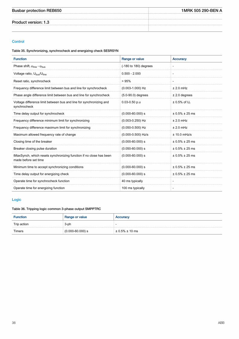
Control
Table 35. Synchronizing, synchrocheck and energizing check SESRSYN
Function Range or value Accuracy
Phase shift, jline - jbus (-180 to 180) degrees -
Voltage ratio, Ubus/Uline 0.500 - 2.000 -
Reset ratio, synchrocheck > 95% -
Frequency difference limit between bus and line for synchrocheck (0.003-1.000) Hz ± 2.0 mHz
Phase angle difference limit between bus and line for synchrocheck (5.0-90.0) degrees ± 2.0 degrees
Voltage difference limit between bus and line for synchronizing andsynchrocheck
0.03-0.50 p.u ± 0.5% of Ur
Time delay output for synchrocheck (0.000-60.000) s ± 0.5% ± 25 ms
Frequency difference minimum limit for synchronizing (0.003-0.250) Hz ± 2.0 mHz
Frequency difference maximum limit for synchronizing (0.050-0.500) Hz ± 2.0 mHz
Maximum allowed frequency rate of change (0.000-0.500) Hz/s ± 10.0 mHz/s
Closing time of the breaker (0.000-60.000) s ± 0.5% ± 25 ms
Breaker closing pulse duration (0.050-60.000) s ± 0.5% ± 25 ms
tMaxSynch, which resets synchronizing function if no close has beenmade before set time
(0.000-60.000) s ± 0.5% ± 25 ms
Minimum time to accept synchronizing conditions (0.000-60.000) s ± 0.5% ± 25 ms
Time delay output for energizing check (0.000-60.000) s ± 0.5% ± 25 ms
Operate time for synchrocheck function 40 ms typically -
Operate time for energizing function 100 ms typically -
Logic
Table 36. Tripping logic common 3-phase output SMPPTRC
Function Range or value Accuracy
Trip action 3-ph -
Timers (0.000-60.000) s ± 0.5% ± 10 ms
Busbar protection REB650 1MRK 505 290-BEN A
Product version: 1.3
38 ABB

Table 37. Configurable logic blocks
Logic block Quantitywithcycletime
Range or value Accuracy
5 ms 20 ms 100 ms
AND 60 60 160 - -
OR 60 60 160 - -
XOR 10 10 20 - -
INVERTER 30 30 80 - -
SRMEMORY 10 10 20 - -
RSMEMORY 10 10 20 - -
GATE 10 10 20 - -
PULSETIMER 10 10 20 (0.000–90000.000) s ± 0.5% ± 25 ms for20 ms cycle time
TIMERSET 10 10 20 (0.000–90000.000) s ± 0.5% ± 25 ms for20 ms cycle time
LOOPDELAY 10 10 20
Table 38. Configurable logic Q/T
Logic block Quantitywith cycletime
Range or value Accuracy
20 ms 100 ms
ANDQT 20 100 - -
ORQT 20 100 - -
XORQT 10 30 - -
INVERTERQT 20 100 - -
RSMEMORYQT 10 30 - -
SRMEMORYQT 15 10 - -
PULSETIMERQT 10 30 (0.000–90000.000) s
± 0.5% ± 25 ms for 20 ms cycle time
TIMERSETQT 10 30 (0.000–90000.000) s
± 0.5% ± 25 ms for 20 ms cycle time
INVALIDQT 6 6 - -
INDCOMBSPQT 10 10 - -
INDEXTSPQT 10 10 - -
Table 39. Elapsed time integrator with limit transgression and overflow supervision TEIGGIO
Function Cycle time (ms) Range or value Accuracy
Elapsed time integration 5 0 ~ 999999.9 s ±0.05% or ±0.01 s
20 0 ~ 999999.9 s ±0.05% or ±0.04 s
100 0 ~ 999999.9 s ±0.05% or ±0.2 s
Busbar protection REB650 1MRK 505 290-BEN A
Product version: 1.3
ABB 39

Monitoring
Table 40. Technical data covering measurement functions: CVMMXN, CMMXU, VMMXU, CMSQI, VMSQI, VNMMXU
Function Range or value Accuracy
Voltage (0.1-1.5) ×Ur ± 0.5% of Ur at U£Ur
± 0.5% of U at U > Ur
Connected current (0.2-4.0) × Ir ± 0.5% of Ir at I £ Ir± 0.5% of I at I > Ir
Active power, P 0.1 x Ur< U < 1.5 x Ur
0.2 x Ir < I < 4.0 x Ir± 1.0% of Sr at S ≤ Sr
± 1.0% of S at S > Sr
Reactive power, Q 0.1 x Ur< U < 1.5 x Ur
0.2 x Ir < I < 4.0 x Ir± 1.0% of Sr at S ≤ Sr
± 1.0% of S at S > Sr
Apparent power, S 0.1 x Ur < U < 1.5 x Ur
0.2 x Ir< I < 4.0 x Ir± 1.0% of Sr at S ≤ Sr
± 1.0% of S at S > Sr
Apparent power, S Three phasesettings
cos phi = 1 ± 0.5% of S at S > Sr
± 0.5% of Sr at S ≤ Sr
Power factor, cos (φ) 0.1 x Ur < U < 1.5 x Ur
0.2 x Ir< I < 4.0 x Ir< 0.02
Table 41. Event counter CNTGGIO
Function Range or value Accuracy
Counter value 0-100000 -
Max. count up speed 10 pulses/s (50% duty cycle) -
Table 42. Limit counter L4UFCNT
Function Range or value Accuracy
Counter value 0-65535 -
Max. count up speed 5-160 pulses/s -
Busbar protection REB650 1MRK 505 290-BEN A
Product version: 1.3
40 ABB
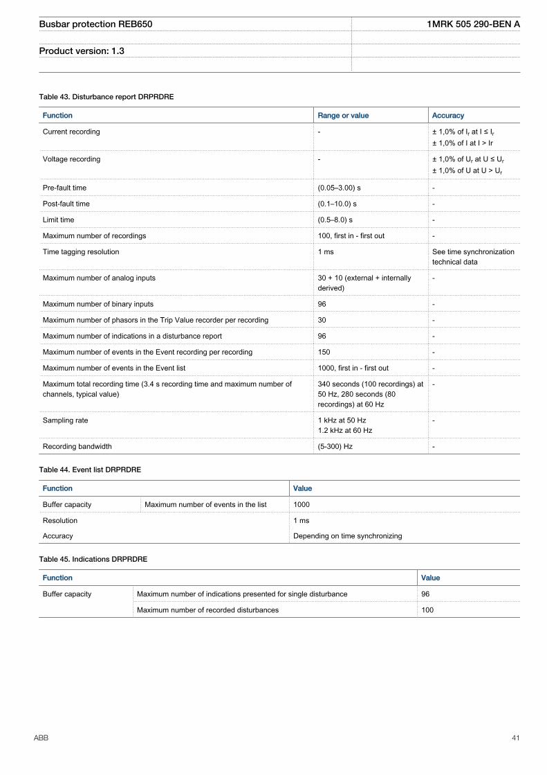
Table 43. Disturbance report DRPRDRE
Function Range or value Accuracy
Current recording - ± 1,0% of Ir at I ≤ Ir± 1,0% of I at I > Ir
Voltage recording - ± 1,0% of Ur at U ≤ Ur
± 1,0% of U at U > Ur
Pre-fault time (0.05–3.00) s -
Post-fault time (0.1–10.0) s -
Limit time (0.5–8.0) s -
Maximum number of recordings 100, first in - first out -
Time tagging resolution 1 ms See time synchronizationtechnical data
Maximum number of analog inputs 30 + 10 (external + internallyderived)
-
Maximum number of binary inputs 96 -
Maximum number of phasors in the Trip Value recorder per recording 30 -
Maximum number of indications in a disturbance report 96 -
Maximum number of events in the Event recording per recording 150 -
Maximum number of events in the Event list 1000, first in - first out -
Maximum total recording time (3.4 s recording time and maximum number ofchannels, typical value)
340 seconds (100 recordings) at50 Hz, 280 seconds (80recordings) at 60 Hz
-
Sampling rate 1 kHz at 50 Hz1.2 kHz at 60 Hz
-
Recording bandwidth (5-300) Hz -
Table 44. Event list DRPRDRE
Function Value
Buffer capacity Maximum number of events in the list 1000
Resolution 1 ms
Accuracy Depending on time synchronizing
Table 45. Indications DRPRDRE
Function Value
Buffer capacity Maximum number of indications presented for single disturbance 96
Maximum number of recorded disturbances 100
Busbar protection REB650 1MRK 505 290-BEN A
Product version: 1.3
ABB 41

Table 46. Event recorder DRPRDRE
Function Value
Buffer capacity Maximum number of events in disturbance report 150
Maximum number of disturbance reports 100
Resolution 1 ms
Accuracy Depending on timesynchronizing
Table 47. Trip value recorder DRPRDRE
Function Value
Buffer capacity
Maximum number of analog inputs 30
Maximum number of disturbance reports 100
Table 48. Disturbance recorder DRPRDRE
Function Value
Buffer capacity Maximum number of analog inputs 40
Maximum number of binary inputs 96
Maximum number of disturbance reports 100
Maximum total recording time (3.4 s recording time and maximum numberof channels, typical value)
340 seconds (100 recordings) at 50 Hz280 seconds (80 recordings) at 60 Hz
Table 49. Station battery supervision SPVNZBAT
Function Range or value Accuracy
Lower limit for the battery terminal voltage (60-140) % of Ubat ± 1.0% of set battery voltage
Reset ratio, lower limit <105 % -
Upper limit for the battery terminal voltage (60-140) % of Ubat ± 1.0% of set battery voltage
Reset ratio, upper limit >95 % -
Timers (0.000-60.000) s ± 0.5% ± 110 ms
Battery rated voltage 20-250V -
Table 50. Insulation gas monitoring function SSIMG
Function Range or value Accuracy
Timers (0.000-60.000) s ± 0.5% ± 110 ms
Table 51. Insulation liquid monitoring function SSIML
Function Range or value Accuracy
Timers (0.000-60.000) s ± 0.5% ± 110 ms
Busbar protection REB650 1MRK 505 290-BEN A
Product version: 1.3
42 ABB

Table 52. Circuit breaker condition monitoring SSCBR
Function Range or value Accuracy
Alarm levels for open and close travel time (0-200) ms ± 0.5% ± 25 ms
Alarm levels for number of operations (0 - 9999) -
Setting of alarm for spring charging time (0.00-60.00) s ± 0.5% ± 25 ms
Time delay for gas pressure alarm (0.00-60.00) s ± 0.5% ± 25 ms
Time delay for gas pressure lockout (0.00-60.00) s ± 0.5% ± 25 ms
Metering
Table 53. Pulse counter PCGGIO
Function Setting range Accuracy
Cycle time for report of countervalue
(1–3600) s -
Table 54. Function for energy calculation and demand handling ETPMMTR
Function Range or value Accuracy
Energy metering MWh Export/Import, MVArhExport/Import
Input from MMXU. No extra error at steady load
Busbar protection REB650 1MRK 505 290-BEN A
Product version: 1.3
ABB 43

Station communication
Table 55. Communication protocol
Function Value
Protocol TCP/IP Ethernet
Communication speed for the IEDs 100 Mbit/s
Protocol IEC 61850–8–1
Communication speed for the IEDs 100BASE-FX
Protocol DNP3.0/TCP
Communication speed for the IEDs 100BASE-FX
Protocol, serial IEC 60870–5–103
Communication speed for the IEDs 9600 or 19200 Bd
Protocol, serial DNP3.0
Communication speed for the IEDs 300–115200 Bd
HardwareIED
Dimensions
Table 56. Dimensions of the IED - 3U full 19" rack
Description Value
Width 442 mm (17.40 inches)
Height 132 mm (5.20 inches), 3U
Depth 249.5 mm (9.82 inches)
Weight box 10 kg (<22.04 lbs)
Busbar protection REB650 1MRK 505 290-BEN A
Product version: 1.3
44 ABB

Inverse time characteristics
Table 57. ANSI Inverse time characteristics
Function Range or value Accuracy
Operating characteristic:
( )1PAt B k tDef
I
æ öç ÷= + × +ç ÷ç - ÷è ø
EQUATION1249-SMALL V2 EN
I = Imeasured/Iset
k = (0.05-999) in steps of 0.01 -
ANSI Extremely Inverse A=28.2, B=0.1217, P=2.0
ANSI Very inverse A=19.61, B=0.491, P=2.0
ANSI Normal Inverse A=0.0086, B=0.0185, P=0.02, tr=0.46
ANSI Moderately Inverse A=0.0515, B=0.1140, P=0.02
ANSI Long Time Extremely Inverse A=64.07, B=0.250, P=2.0
ANSI Long Time Very Inverse A=28.55, B=0.712, P=2.0
ANSI Long Time Inverse A=0.086, B=0.185, P=0.02
Table 58. IEC Inverse time characteristics
Function Range or value Accuracy
Operating characteristic:
( )1= ×
-
æ öç ÷ç ÷è ø
P
At k
I
EQUATION1251-SMALL V1 EN
I = Imeasured/Iset
k = (0.05-999) in steps of 0.01 -
IEC Normal Inverse A=0.14, P=0.02
IEC Very inverse A=13.5, P=1.0
IEC Inverse A=0.14, P=0.02
IEC Extremely inverse A=80.0, P=2.0
IEC Short time inverse A=0.05, P=0.04
IEC Long time inverse A=120, P=1.0
The parameter setting Characterist1 and 4/Reserved shall not be used, since this
parameter setting is for future use and notimplemented yet.
Busbar protection REB650 1MRK 505 290-BEN A
Product version: 1.3
ABB 45

Table 59. RI and RD type inverse time characteristics
Function Range or value Accuracy
RI type inverse characteristic
1
0.2360.339
= ×
-
t k
IEQUATION1137-SMALL V1 EN
I = Imeasured/Iset
k = (0.05-999) in steps of 0.01
RD type logarithmic inverse characteristic
5.8 1.35= - ×æ öç ÷è ø
tI
Ink
EQUATION1138-SMALL V1 EN
I = Imeasured/Iset
k = (0.05-999) in steps of 0.01
Table 60. Inverse time characteristics for overvoltage protection
Function Range or value Accuracy
Type A curve:
=- >
>
æ öç ÷è ø
tk
U U
U
EQUATION1436-SMALL V1 EN
U> = Uset
U = Umeasured
k = (0.05-1.10) in steps of 0.01 ±5% +60 ms
Type B curve:
2.0
480
32 0.5 0.035
=×
- >× - -
>
æ öç ÷è ø
tk
U U
U
EQUATION1437-SMALL V1 EN
k = (0.05-1.10) in steps of 0.01
Type C curve:
3.0
480
32 0.5 0.035
=×
- >× - -
>
æ öç ÷è ø
tk
U U
U
EQUATION1438-SMALL V1 EN
k = (0.05-1.10) in steps of 0.01
Busbar protection REB650 1MRK 505 290-BEN A
Product version: 1.3
46 ABB

Table 61. Inverse time characteristics for undervoltage protection
Function Range or value Accuracy
Type A curve:
=< -
<
æ öç ÷è ø
kt
U U
UEQUATION1431-SMALL V1 EN
U< = Uset
U = UVmeasured
k = (0.05-1.10) in steps of 0.01 ±5% +60 ms
Type B curve:
2.0
4800.055
32 0.5
×= +
< -× -
<
æ öç ÷è ø
kt
U U
U
EQUATION1432-SMALL V1 EN
U< = Uset
U = Umeasured
k = (0.05-1.10) in steps of 0.01
Table 62. Inverse time characteristics for residual overvoltage protection
Function Range or value Accuracy
Type A curve:
=- >
>
æ öç ÷è ø
tk
U U
U
EQUATION1436-SMALL V1 EN
U> = Uset
U = Umeasured
k = (0.05-1.10) in steps of0.01
±5% +70 ms
Type B curve:
2.0
480
32 0.5 0.035
=×
- >× - -
>
æ öç ÷è ø
tk
U U
U
EQUATION1437-SMALL V1 EN
k = (0.05-1.10) in steps of0.01
Type C curve:
3.0
480
32 0.5 0.035
=×
- >× - -
>
æ öç ÷è ø
tk
U U
U
EQUATION1438-SMALL V1 EN
k = (0.05-1.10) in steps of0.01
Busbar protection REB650 1MRK 505 290-BEN A
Product version: 1.3
ABB 47
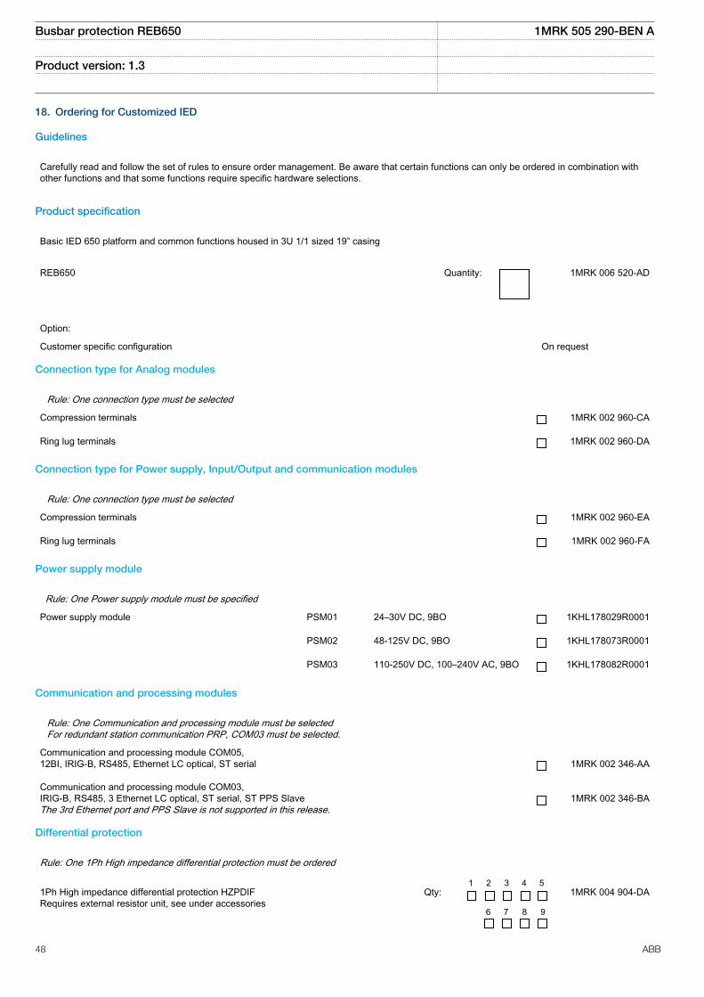
18. Ordering for Customized IED
Guidelines
Carefully read and follow the set of rules to ensure order management. Be aware that certain functions can only be ordered in combination withother functions and that some functions require specific hardware selections.
Product specification
Basic IED 650 platform and common functions housed in 3U 1/1 sized 19” casing
REB650 Quantity: 1MRK 006 520-AD
Option:
Customer specific configuration On request
Connection type for Analog modules
Rule: One connection type must be selected
Compression terminals 1MRK 002 960-CA
Ring lug terminals 1MRK 002 960-DA
Connection type for Power supply, Input/Output and communication modules
Rule: One connection type must be selected
Compression terminals 1MRK 002 960-EA
Ring lug terminals 1MRK 002 960-FA
Power supply module
Rule: One Power supply module must be specified
Power supply module PSM01 24–30V DC, 9BO 1KHL178029R0001
PSM02 48-125V DC, 9BO 1KHL178073R0001
PSM03 110-250V DC, 100–240V AC, 9BO 1KHL178082R0001
Communication and processing modules
Rule: One Communication and processing module must be selectedFor redundant station communication PRP, COM03 must be selected.
Communication and processing module COM05,12BI, IRIG-B, RS485, Ethernet LC optical, ST serial
1MRK 002 346-AA
Communication and processing module COM03,IRIG-B, RS485, 3 Ethernet LC optical, ST serial, ST PPS SlaveThe 3rd Ethernet port and PPS Slave is not supported in this release.
1MRK 002 346-BA
Differential protection
Rule: One 1Ph High impedance differential protection must be ordered
1Ph High impedance differential protection HZPDIFRequires external resistor unit, see under accessories
Qty:
1 2 3 4 5
6 7 8 9
1MRK 004 904-DA
Busbar protection REB650 1MRK 505 290-BEN A
Product version: 1.3
48 ABB

Logic
Rule: One Tripping logic must be ordered
Tripping logic, common 3–phase output SMPPTRC
Qty:
1 2 3 4 5 6 1MRK 004 922-AA
Optional functionsCurrent protection
Four step phase overcurrent protection, 3–phase output OC4PTOC Qty: 1MRK 004 908-BC
Four step residual overcurrent protection, zero/negative sequence direction EF4PTOC Qty: 1MRK 004 908-FA
Thermal overload protection, two time constants TRPTTR Qty: 1MRK 004 908-KB
Breaker failure protection, 3–phase activation and output CCRBRF Qty: 1MRK 004 908-LA
Pole discordance protection CCRPLD Qty: 1MRK 004 908-NA
Negative sequence based overcurrent function DNSPTOC Qty: 1MRK 004 908-TB
Voltage protection
Two step undervoltage protection UV2PTUV
Qty:
1 2 1MRK 004 910-AB
Two step overvoltage protection OV2PTOV
Qty:
1 2 1MRK 004 910-BB
Two step residual overvoltage protection ROV2PTOV
Qty:
1 2 1MRK 004 910-CB
Secondary system supervision
Fuse failure supervision SDDRFUF
Qty:
1 2 1MRK 004 914-BA
Control
Synchrocheck, energizing check and synchronizing SESRSYN Qty: 1MRK 004 917-AC
Rule: Only CBC3 or APC8 can be ordered
Apparatus control for single bay, max 8 app. 1CB incl. interlocking APC8 Qty: 1MRK 004 917-GA
Circuit breaker for 3 CB, CBC3 Qty: 1MRK 004 918-CA
Logic
Configurable logic blocks Q/T 1MRK 002 917-MK
Busbar protection REB650 1MRK 505 290-BEN A
Product version: 1.3
ABB 49

Monitoring
Station battery supervision SPVNZBAT Qty: 1MRK 004 925-HB
Insulation gas monitoring function SSIMG
Qty:
1 2 1MRK 004 925-KA
Insulation liquid monitoring function SSIML
Qty:
1 2 1MRK 004 925-LA
Circuit breaker condition monitoring SSCBR Qty: 1MRK 004 925-MA
First local HMI user dialogue language
HMI language, English IEC Always included
Additional local HMI user dialogue language
HMI language, English US 1MRK 002 940-MA
Optional hardwareHuman machine interface
Rule: One must be ordered.
Display type Keypad symbol Case size
Local human machine interface LHMI01 IEC 3U 1/1 19" 1KHL160055R0001
Local human machine interface LHMI01 ANSI 3U 1/1 19" 1KHL160042R0001
Analog system
Rule: One Transformer input module must be ordered
Transformer module TRM01 6I+4U, 1/5A,100/220V Qty: 1KHL178083R0001
Transformer module TRM01 8I+2U, 1/5A, 100/220V Qty: 1KHL178083R0013
Transformer module TRM01 4I, 1/5A+1I, 0.1/0.5A+5U, 100/220V Qty: 1KHL178083R0016
Transformer module TRM01 4I+6U, 1/5A, 100/220V Qty: 1KHL178083R0003
Rule: Only one Analog input module can be ordered
Analog input module AIM01 6I+4U, 1/5A, 100/220V Qty: 1KHL178083R5001
Analog input module AIM01 4I, 1/5A+1I, 0.1/0.5A+5U, 100/220V Qty: 1KHL178083R5016
Binary input/output modules
Note: If analog input module AIM is ordered only 2 BIO modules can be ordered
Binary input/output module BIO01 Qty: 1 2 3 4 1KHL178074R0001
Rack mounting kit
Rack mounting kit for 3U 1/1 x 19” case Quantity: 1KHL400352R0001
Busbar protection REB650 1MRK 505 290-BEN A
Product version: 1.3
50 ABB

19. Ordering for Configured IED
GuidelinesCarefully read and follow the set of rules to ensure order management.Please refer to the available functions table for included application functions.
To obtain the complete ordering code, please combine code from the tables, as given in the example below.
Example code: REB650*1.3-A03X00-X00-B1X0-D-H-SA-E-SA1B1-AA-F. Using the code of each position #1-11 specified as REB650*1-2 2-3-44-5-6-7 7-8-9 9 9-10 10-11
# 1 - 2 - 3 - 4 - 5 - 6 - 7 - 8 - 9 - 10 - 11
REB650* - - - - - - - - - -
Po
sitio
n
SOFTWARE #1 Notes and Rules
Version number
Version no 1.3
Selection for position #1. 1.3
Configuration alternatives #2 Notes and Rules
High impedance busbar protection A03
ACT configuration
ABB standard configuration X00
Selection for position #2. X00
Software options #3 Notes and Rules
No option X00
Selection for postition #3 X00
First HMI language #4 Notes and Rules
English IEC B1
Selection for position #4.
Additional HMI language #4
No second HMI language X0
Selection for position #4. B1 X0
Casing #5 Notes and Rules
Rack casing, 3U 1/1 x 19" D
Selection for position #5. D
Mounting details #6 Notes and Rules
No mounting kit included X
Rack mounting kit for 3U 1/1 x 19" H
Selection for position #6.
Busbar protection REB650 1MRK 505 290-BEN A
Product version: 1.3
ABB 51
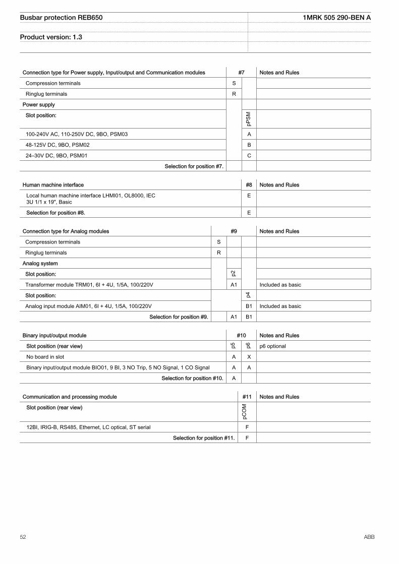
Connection type for Power supply, Input/output and Communication modules #7 Notes and Rules
Compression terminals S
Ringlug terminals R
Power supply
Slot position:
pPSM
100-240V AC, 110-250V DC, 9BO, PSM03 A
48-125V DC, 9BO, PSM02 B
24–30V DC, 9BO, PSM01 C
Selection for position #7.
Human machine interface #8 Notes and Rules
Local human machine interface LHMI01, OL8000, IEC3U 1/1 x 19", Basic
E
Selection for position #8. E
Connection type for Analog modules #9 Notes and Rules
Compression terminals S
Ringlug terminals R
Analog system
Slot position: p2
Transformer module TRM01, 6I + 4U, 1/5A, 100/220V A1 Included as basic
Slot position: p4
Analog input module AIM01, 6I + 4U, 1/5A, 100/220V B1 Included as basic
Selection for position #9. A1 B1
Binary input/output module #10 Notes and Rules
Slot position (rear view) p5 p6 p6 optional
No board in slot A X
Binary input/output module BIO01, 9 BI, 3 NO Trip, 5 NO Signal, 1 CO Signal A A
Selection for position #10. A
Communication and processing module #11 Notes and Rules
Slot position (rear view)
pCO
M
12BI, IRIG-B, RS485, Ethernet, LC optical, ST serial F
Selection for position #11. F
Busbar protection REB650 1MRK 505 290-BEN A
Product version: 1.3
52 ABB

20. Ordering for Accessories
External resistor unit
High impedance resistor unit 1-ph with resistor and voltage dependent resistor for20-100V operating voltage
Quantity:
1 2 3 4 5
6 7 8 9
RK 795 101-MA
High impedance resistor unit 3-ph with resistor and voltage dependent resistor for20-100V operating voltage
Quantity:
1 2 3 RK 795 101-MB
High impedance resistor unit 1-ph with resistor and voltage dependent resistor for100-400V operating voltage
Quantity:
1 2 3 4 5
6 7 8 9
RK 795 101-CB
High impedance resistor unit 3-ph with resistor and voltage dependent resistor for100-400V operating voltage
Quantity:
1 2 3 RK 795 101-DC
Configuration and monitoring tools
Front connection cable between LCD-HMI and PC Quantity: 1MRK 001 665-CA
LED Label special paper A4, 1 pc Quantity: 1MRK 002 038-CA
LED Label special paper Letter, 1 pc Quantity: 1MRK 002 038-DA
Manuals
Note: One (1) IED Connect DVD containing user documentationOperation manualTechnical manualInstallation manualCommissioning manualApplication manualCommunication protocol manual, DNP3Communication protocol manual, IEC61850-8-1Communication protocol manual, IEC60870-5-103Cyber security deployment guidelinesType test certificateEngineering manualPoint list manual, DNP3Connectivity packages and LED label template is always included for each IED
Rule: Specify additional quantity of IED Connect DVD requested
User documentation Quantity: 1MRK 003 500-AA
Busbar protection REB650 1MRK 505 290-BEN A
Product version: 1.3
ABB 53
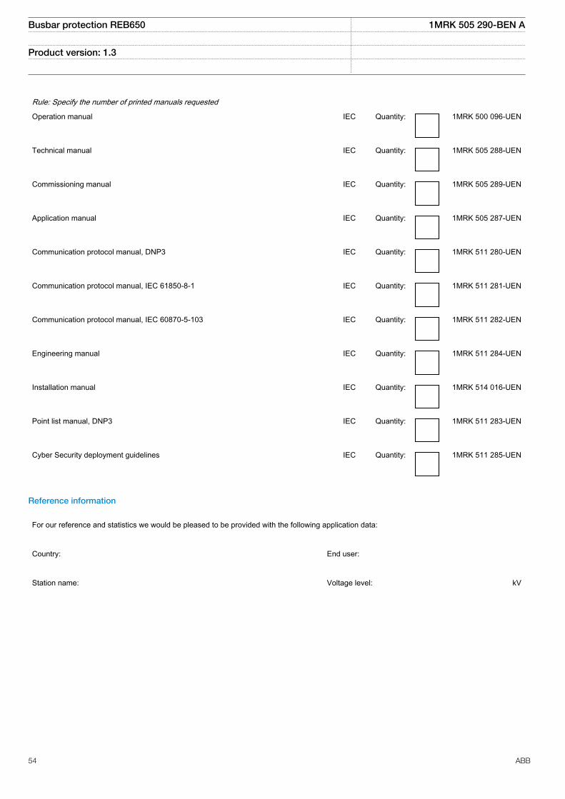
Rule: Specify the number of printed manuals requested
Operation manual IEC Quantity: 1MRK 500 096-UEN
Technical manual IEC Quantity: 1MRK 505 288-UEN
Commissioning manual IEC Quantity: 1MRK 505 289-UEN
Application manual IEC Quantity: 1MRK 505 287-UEN
Communication protocol manual, DNP3 IEC Quantity: 1MRK 511 280-UEN
Communication protocol manual, IEC 61850-8-1 IEC Quantity: 1MRK 511 281-UEN
Communication protocol manual, IEC 60870-5-103 IEC Quantity: 1MRK 511 282-UEN
Engineering manual IEC Quantity: 1MRK 511 284-UEN
Installation manual IEC Quantity: 1MRK 514 016-UEN
Point list manual, DNP3 IEC Quantity: 1MRK 511 283-UEN
Cyber Security deployment guidelines IEC Quantity: 1MRK 511 285-UEN
Reference information
For our reference and statistics we would be pleased to be provided with the following application data:
Country: End user:
Station name: Voltage level: kV
Busbar protection REB650 1MRK 505 290-BEN A
Product version: 1.3
54 ABB

Related documents
Documents related to REB650 Identity number
Application manual 1MRK 505 287-UEN
Technical manual 1MRK 505 288-UEN
Commissioning manual 1MRK 505 289-UEN
Product Guide, configured 1MRK 505 290-BEN
Type test certificate 1MRK 505 290-TEN
Application notes for Circuit Breaker Control 1MRG006806
650 series manuals Identity number
Communication protocol manual, DNP 3.0 1MRK 511 280-UEN
Communication protocol manual, IEC 61850–8–1 1MRK 511 281-UEN
Communication protocol manual, IEC 60870-5-103 1MRK 511 282-UEN
Cyber Security deployment guidelines 1MRK 511 285-UEN
Point list manual, DNP 3.0 1MRK 511 283-UEN
Engineering manual 1MRK 511 284-UEN
Operation manual 1MRK 500 096-UEN
Installation manual 1MRK 514 016-UEN
Accessories, 650 series 1MRK 513 023-BEN
MICS 1MRG 010 656
PICS 1MRG 010 660
PIXIT 1MRG 010 658
Busbar protection REB650 1MRK 505 290-BEN A
Product version: 1.3
ABB 55

56

Contact us
ABB ABSubstation Automation ProductsSE-721 59 Västerås, SwedenPhone +46 (0) 21 32 50 00Fax +46 (0) 21 14 69 18
www.abb.com/substationautomation
1MR
K 5
05 2
90-B
EN
A©
Cop
yrig
ht 2
013
AB
B. A
ll rig
hts
rese
rved
.