business process modelling based computer … · functional requirement generation su, m.onur ......
TRANSCRIPT

BUSINESS PROCESS MODELLING BASED COMPUTER-AIDED SOFTWARE FUNCTIONAL REQUIREMENTS GENERATION
A THESIS SUBMITTED TO
THE GRADUATE SCHOOL OF INFORMATICS
OF
THE MIDDLE EAST TECHNICAL UNIVERSITY
BY
M. ONUR SU
IN PARTIAL FULFILLMENT OF THE REQUIREMENTS FOR THE DEGREE
OF
MASTER OF SCIENCE
IN
THE DEPARTMENT OF INFORMATION SYSTEMS
JANUARY 2004

I hereby declare that all information in this document has been obtained and
presented in accordance with academic rules and ethical conduct. I also declare
that, as required by these rules and conduct, I have fully cited and referenced all
material and results that are not original to this work.
__________________________
Mehmet Onur Su
Approval of the Graduate School of Informatics
__________________________
Prof. Dr. Nese YALABIK
Director
I certify that this thesis satisfies all the requirements as a thesis for the degree of
Master of Science/Doctor of Philosophy.
__________________________
Assoc. Prof. Dr. Onur Demirörs
Head of Department
This is to certify that we have read this thesis and that in our opinion it is fully
adequate, in scope and quality, as a thesis for the degree of Master of Science.
__________________________
Assoc. Prof. Dr. Onur Demirörs
Supervisor
Examining Committee Members Prof. Dr. Semih BILGEN __________________________ Assoc. Prof. Dr. Onur DEMIRÖRS __________________________ Assoc. Prof. Dr. Bilge SAY __________________________ Assoc. Prof. Dr. Kadir VAROGLU __________________________ Dr. Altan KOÇYIGIT __________________________
iii
ABSTRACT
BUSINESS PROCESS MODELLING BASED COMPUTER-AIDED
SOFTWARE FUNCTIONAL REQUIREMENT GENERATION
Su, M.Onur
M.S., Department of Information Systems
Supervisor: Assoc. Prof. Dr. Onur Demirörs
January 2004, 114 pages
Problems of requirements which are identified in the earlier phase of a
software development project can deeply affect the success of the project. Thus
studies which aim to decrease these problems are crucial. Automation is foreseen
to be one of the possible solutions for decreasing or removing some of the
problems originating from requirements.
This study focuses on the development and implementation of an automated
tool that will generate requirements in natural language from business process
models. In this study, The benefits of the tool are discussed, and the tool is
compared with other software requirements related tools with respect to their
functionality. The developed tool has been tested within a large military project
and the results of using the tool are presented.
Keywords: Requirement, Requirement Engineering, Business Process
Modelling, Automatic Requirement Generation, eEPC, KAOS

iv
ÖZ
IS SÜREÇLERI MODELLEMEYE DAYALI BILGISAYAR DESTEKLI
YAZILIM FONKSIYONEL GEREKSINIM ÜRETIMI
Su, M.Onur
Yüksek Lisans, Bilisim Sistemleri
Tez Yöneticisi: Doç.Dr.Onur Demirörs
Ocak 2004, 114 sayfa
Yazilimin sorunlari üzerine yapilan arastirmalarda, yazilimin ilk fazinda
tanimlanan gereksinimler ile ilgili ortaya çikan sorunlarin, yazilim projelerinin
basarisini derinden etkiledigi bilinmektedir. Dolayisiyla bu sorunu azaltmayi
hedefleyen çalismalarin önemi büyüktür. Otomasyon, gereksinimden kaynaklanan
sorunlarin bazilarini azaltmak, bazilarini ise ortadan kaldirmak için çözüm olarak
öngörülen yollardan biridir.
Bu çalisma, yazilimin ilk sürecinde belirlenen fonksiyonel gereksinimlerin,
dogal dille is süreç modellerinden otomatik olarak üretecek bir aracin gelistirme
ve gerçeklestirmesine dayanmaktadir. Çalismada ayrica, gelistirilen aracin
faydalari tartisilmakta, yazilim gereksinimleri ile etkilesimli olarak çalisan diger
araçlar ile bu araç görevlerine göre karsilastirilmaktadir. “Büyük” kapsamindaki
bir askeri proje ile gelistirdigimiz araç sinanmis ve sonuçlari sunulmustur.
Anahtar Kelimeler: Gereksinim, Gereksinim Mühendisligi, Is Seri
Modelleme, Otomatik Gereksinim Üretme, eEPC, KAOS

v
DEDICATION
To my parents who always believe in me,
To the memory of my Grandfather, Mehmet SU

vi
ACKNOWLEDGMENTS
I express sincere thanks to my advisor Assoc.Prof.Dr.Onur Demirörs for
providing insight and guidance as well as encouragement and inspiration
throughout this research. I am grateful to him for his continuing enthusiasm and
his perfect balance between providing me direction and encouraging
independence.
I would like to express my deepest gratitude and appreciation to my family
who have always given me their love and emotional support.
I also would like to give particular thanks to each special project members
who always helped me with my questions.

vii
TABLE OF CONTENTS
ABSTRACT.........................................................................................................III
ÖZ......................................................................................................................... IV
DEDICATION.......................................................................................................V
ACKNOWLEDGMENTS ..................................................................................VI
TABLE OF CONTENTS...................................................................................VII
LIST OF TABLES .............................................................................................. IX
LIST OF FIGURES ..............................................................................................X
LIST OF ACRONYMS.......................................................................................XI
CHAPTER
1. INTRODUCTION......................................................................................... 1
1.1. Statement of Problem....................................................................................................................3
1.2. Approach ..........................................................................................................................................4
1.3. Thesis Structure..............................................................................................................................5
2. RELATED RESEARCH .............................................................................. 6
2.1. Requirement Engineering ............................................................................................................6 2.1.1. Requirement.................................................................................................................................7
2.2. Business Process Modelling ...................................................................................................... 10
2.3. ARIS Concept............................................................................................................................... 12 2.3.1. EPC Method...............................................................................................................................18 2.3.2. eEPC Method.............................................................................................................................23 2.3.3. ARIS Tool ..................................................................................................................................30

viii
2.4. Tool Support for Requirement Engineering ........................................................................ 31 2.4.1. Automatic Requirements Generation Tools .........................................................................34
3. KAOS TOOL............................................................................................... 36
3.1. Tool Scenario................................................................................................................................ 37
3.2. Software Design........................................................................................................................... 40 3.2.1. Description of Classes ..............................................................................................................41 3.2.2. Class Diagrams of Objects ......................................................................................................46 3.2.3. Description of Sub-Programs ..................................................................................................48 3.2.4. Structure Charts of Sub-Programs ..........................................................................................65
3.3. Tool Restrictions .......................................................................................................................... 66 3.3.1. Assumptions...............................................................................................................................66 3.3.2. Constraints..................................................................................................................................67
3.4. Sentence Structure ...................................................................................................................... 74 3.4.1. Example sentences ....................................................................................................................83
4. EXPERIMENTAL STUDY........................................................................ 86
4.1. Description of Experimental Study ........................................................................................ 86
4.2. The Context of the Experimental Study................................................................................ 87 4.2.1. Concept Explorations ...............................................................................................................89 4.2.2. AS-IS Business Process Modelling........................................................................................89 4.2.3. AS-IS BPM Verification and Validation ..............................................................................90 4.2.4. TO-BE Business Process Modelling......................................................................................91 4.2.5. TO-BE BPM Verification and Validation ............................................................................94 4.2.6. System Requirement Specification ........................................................................................95 4.2.7. System Requirement Verification and Validation...............................................................98
4.3. Application of the Tool .............................................................................................................. 99
5. CONCLUSION.......................................................................................... 102
5.1. Summary......................................................................................................................................102
5.2. Contributions..............................................................................................................................103
5.3. Future Work ...............................................................................................................................105
REFERENCES .................................................................................................. 106
APPENDIX ........................................................................................................ 109

ix
LIST OF TABLES
Table 1 EPC notation ............................................................................................ 19 Table 2 eEPC notation........................................................................................... 23 Table 3 Colour code of KAOS tool....................................................................... 67 Table 4 Example for naming objects..................................................................... 73 Table 5 Description of main dynamic sentence constructs................................... 75 Table 6 Main constructs of sentence structures .................................................... 76 Table 7 Sub-constructs of sentence structures (prefix) ......................................... 79 Table 8 Reasons of corrections ............................................................................. 99

x
LIST OF FIGURES
Figure 1 Hierarchical decomposition of the requirements engineering domain ..... 7 Figure 2 ARIS view............................................................................................... 14 Figure 3 The relationship between views and classes........................................... 15 Figure 4 ARIS phase model .................................................................................. 16 Figure 5 ARIS house ............................................................................................. 18 Figure 6 Example EPC.......................................................................................... 22 Figure 7 Example for eEPC .................................................................................. 30 Figure 8 Classification of RE tools ....................................................................... 32 Figure 9-a The scenario of KAOS tool ................................................................. 39 Figure 9-b The scenario of KAOS tool................................................................. 40 Figure 10 Generalization relationships of classes................................................. 47 Figure 11 Dependency relationships of classes..................................................... 47 Figure 12 Association relationships of the classes................................................ 48 Figure 13 Structure charts of sub-programs .......................................................... 66 Figure 14 Example eEPC for requirement sentences............................................ 84 Figure 15 The structure of the team...................................................................... 87 Figure 16 The uppermost process in eEPC........................................................... 88 Figure 17 AS-IS BPM........................................................................................... 90 Figure 18-a TO-BE BPM ...................................................................................... 93 Figure 18-b TO-BE BPM...................................................................................... 94 Figure 19-a System requirement specification...................................................... 97 Figure 19-b System requirement specification...................................................... 98 Figure 20 KAOS tool step 1 ................................................................................ 110 Figure 21 KAOS tool step 2 ................................................................................ 111 Figure 22 KAOS tool step 3 ................................................................................ 111 Figure 23 KAOS tool step 4 ................................................................................ 112 Figure 24 KAOS tool step 5 ................................................................................ 112 Figure 25 KAOS tool step 6 ................................................................................ 113 Figure 26 KAOS tool step 7 ................................................................................ 113 Figure 27 KAOS tool step 8 ................................................................................ 114 Figure 28 KAOS tool step 9 ................................................................................ 114

xi
LIST OF ACRONYMS
ABS Activity Based Costing
ARIS Architecture of Integrated Information Systems
BPM Business Process Model
BPR Business Process Reengineering
C4ISR Command, Control, Communications, Computers, Intelligence, Surveillance and Reconnaissance
COTS Commercial Off the Shelf
DD Data Dictionary
eEPC Extended Event Driven Process Chain
EPC Event Driven Process Cha in
ESPITI The European Software Process Improvement Training Initiative
FP Function Point
HOBE House of Business Engineering
IEEE Institute of Electrical and Electronics Engineers
INCOSE International Council on System Engineering
IS Information System
ISO International Standards Organisation
IT Information Technology
IWi The Institute for Information Systems
METU Middle East Technical University
OLE Object Linking and Embedding
OTN Object Type Number
RFP Request for Proposal
RGT Requirements Generation Tools
RMT Requirements Management Tools

xii
WBS Work Breakdown Structure

1
CHAPTER 1
1. INTRODUCTION
Requirements are the most important assets of software engineering
activities because the following software engineering activities are built on
elicited requirements. As Brooks wrote “…No other part of the work so cripples
the resulting system if done wrong. No other part is more difficult to rectify
later…” [Brooks, 1987]. However, requirements errors are abundant in software
projects and can easily consume 25%–40% of the total project budget [Yourdon,
2000].
One of the studies carried by Jerry Weinberg discovered that up to 60% of
errors originated from the requirements and analysis activities [Robertson,
Robertson, 2002]. The Standish Group study also supports the findings of Jerry
Weinberg. According to the The Standish Group, at least a third of the
development projects run into trouble for reasons which are directly related to
requirements gathering, requirements documenting, and requirements
management [Yourdon, 2000]. The other survey conducted by The European
Software Process Improvement Training Initiative (ESPITI) has even more
striking results concerning the requirements problem. The main motivation of the
ESPITI survey was to identify the relative importance of various types of software
problems in industry [Yourdon, 2000]. Requirements specifications, managing
customer requirements and documentation are three largest problems for the
responses. “Both the Standish and the ESPITI studies provide qualitative data
indicating that respondents feel that requirements problems appear to transcend
2
other issues in terms of the risks and problems they pose to the application
development.” [Yourdon, 2000, pg.26]
Requirements and the problems associated with requirements are very
important for a project lifecycle. The 1994 study of Capers Jones discovered that
requirements errors and documentation errors together are more than one third of
the total delivered defects pile [Yourdon, 2000]. It is easy, cost effective and time
effective to fix problems caused by requirements in the early stages. The
relationship between cost and requirements errors has been determined by another
study which is performed at various companies including GTE, TRW, IBM and
HP. According to the study, as much as a 200:1 cost saving can be achieved
between the requirements stage and maintenance stage [Yourdon, 2000].
Studies show that one of the major problems concerns requirements and the
activities related to requirements. Requirements problems are strong sources of
potential risks that could adversely impact the project’s resources, schedules, and
products deeply [Wilson, 1999]. It is necessary to use any method, approach
and/or tool that will reduce the problems associated with requirements and also
support requirements engineering activities.
Competitive pressures have increased the expectation of software intensive
products therefore, the functionality of software intensive products has increased
and this results in an increased number of requirements. A number of tools have
been developed to assist or automate requirements activities to handle the
increased number of requirements. These tools are called “Requirements
Engineering Tools” and can be classified as “Requirements Management Tools”
(RMT) and “Requirements Generation Tools” (RGT) (See Figure 8, pg 30). RMT
are basically used to classify requirements and serve to trace the source of
requirements. These tools can be used after requirements are generated. On the
other hand, RGT are used to form requirements in an organized manner. There are
many commercial RMT such as RequisitePro, DOORS, Caliber, CARE, CORE,
Catalyze, Cradle etc… whereas there are only a few RGT [INCOSE, 2002b]. In
the literature, there is only one study found generating requirements from UML
diagrams [Berenbach, 2003] (see Section 2.4.1 for further information about the
3
study) but there is no study in the literature which shows the generating of
functional requirements from business process models.
The KAOS tool is an RGT which has been developed as part of the studies
performed in this thesis and it generates system level software functional
requirements from business process models.
1.1. Statement of Problem
The Performing Rights Society, PROMS project was abandoned in 1992
after spending £11 million. The prominent factor in the cancellation of the project
was poor requirements engineering. It was reported that they failed to set out the
requirements in a form that could be understood and checked by non-technical
people and that the specifications were ill-conceived [Bray, 2002]. Although
critical, elicitation and documenting the initial requirements of customers is only
part of the whole task. Software requirements frequently change during the
process of gathering them. Manual changes are annoying, time consuming and
error prone. One way to address these problems is to automate functional
requirements generation.
Automating requirements generation is a challenging but also a rewarding
research area. Its challenge is mostly due to the difficulties related with the
identification and representation of customer’s need. The rewards include
minimizing effort of non-value-added tasks such as rework and documentation
and improving the quality as well as the ability to modify the requirements
documents.
As the number of requirements for software intensive systems are high, it is
difficult and time consuming to put together requirements in a structured way.
Traditionally software requirements are written in natural language, manually and
in most projects by more than one person. As more engineers work on integrated
parts of documents, consistency becomes a major problem and the task to find and
correct these errors is complicated. Most of the time it is even difficult for a
reviewer to decide whether these requirements are written on purpose or there are
requirements which are skipped.

4
Moreover, it is possible to write the same requirement in different styles,
therefore the recipients of the requirements document have to adapt to different
styles of writers. If requirements are consistently written in a structured way,
comprehensible documents can be generated so that clients can check and
understand resulting requirements document.
Current software engineering tools are mainly focused on software
requirements and use approaches which start with software requirements so there
is no sufficient tool support for system level requirements.
On the whole, the aim of this thesis is to develop a tool to automatically
generate system level functional requirements in natural language from business
processes. The tool will enable to construct the requirements within a short time,
enable re-construction based on changes in business processes, construct sentence
structures consistently to improve understanding and enable requirements
management tools to ease further requirements based tasks.
1.2. Approach
Business Process Modelling (BPM) was utilized as an approach for
automatic requirements generation. An appropriate business process modelling
language can offer the opportunity to generate requirements in natural language.
Extended Event Driven Process Chain Modelling (eEPC Modelling) was used
with ARIS concept for AS-IS and TO-BE studies so that roles, inputs, outputs and
their relationships could be shown precisely, functions could be presented in
natural business language.
There were specific activities followed step by step to generate functional
requirements in natural language. First of all, the base components of
requirements sentences called sentence construct was determined. The
requirements of a similar project were analyzed to identify specific needs of
requirements sentences and restrictions. Then restrictions were enlarged for the
experimental study and the sentence structures were determined. The tool called
KAOS was formed using findings and it was validated by an experimental study
which was a large military project.

5
The experimental study was performed in part of requirements elicitation
process as defined in the article “Utilizing Business Process Models for
Requirements Elicitation: A Large System Acquisition Experience” [Demirörs,
Tarhan, Gencel, 2002]. The steps of the process are concept exploration, analysis
and modelling of current business processes which is called AS-IS Study,
modelling target business processes which is called TO-BE Study, requirements
generation for the target system which is called system requirement specification
and verification and validation of outputs.
1.3. Thesis Structure
Chapter 2, related research, provides a detailed description and information
from the literature which are necessary for the study.
Chapter 3, The KAOS tool, presents detailed information about tool and the
sentence structures.
Chapter 4, The experimental study, contains motivation, the process which
is applied during the experimental study, structure of project team and results.
Chapter 5, provides the conclusion to the study, includes contributions and
directions for future work.

6
CHAPTER 2
2. RELATED RESEARCH
2.1. Requirements Engineering
Requirements engineering (RE) is the systematic process of developing
requirements through an iterative co-operative process of analyzing the problem,
documenting resulting observation in a variety of representation formats, and
checking the accuracy of the understanding gained [Macaulay, 1996]. In addition
to this, requirement s engineering deals with the problems associated with this
stage.
Requirements engineering consists of two main interconnected, as shown in
Figure 1. These are requirements development and requirement management
[Wiegers, 1999a]. In addition to this, requirements development consists of sub
domains such as elicitation, analysis, specification and verification. The sub-
disciplines encompass all the activities involved with gathering, evaluating, and
documenting the requirements for a software or software containing product
[Wiegers, 1999a].

7
Figure 1 Hierarchical decomposition of the requirements engineering domain [Wiegers, 1999a]
2.1.1. Requirement
Quality products can be produced by quality raw materials, thus poor
requirements can not lead to excellent software [Wiegers, 1999b]. Requirements
are the raw materials of software intensive projects so requirements are the most
important assets that software intensive projects own.
It is very important to define all aspects of requirements to use a common
language because the software society has made many definitions such as:
“A requirement is something that the product must do or a quality that the
product must have.” [Robertson, Robertson, 2002, pg.5]
“The effect that client wishes to be brought about in the problem are
requirements themselves.” [Bray, 2002,pg.14]
The IEEE Standard glossary of software engineering terminology defines
requirements as:
i. A condition or capability needed by a user to solve a
problem or achieve an objective.
ii. A condition or capability that must be met or possessed
by a system or system component to satisfy a contract,
standard, specification, or other formally imposed
document.
Requirements Management
Requirements Engineering
Requirements Development
Verification Analysis Elicitation Specification

8
iii. A documented representation of a condition or capability
as in 1 or 2 [Christel, Kang, 1999,pg.2].
Although the definitions above are common, it is not adequate to understand
the nature of requirements and to speak common language. In other words, there
are other aspects of requirements which need to be clarified. The requirements can
also be classified with abstraction level and type;
Classification 1: Abstraction Level
There are many sub-classifications in relation to the abstraction levels and
points of views but the closest to the approach of this thesis is that of Soren
Lausen. She classifies the requirements considering abstraction level as follows:
[Lausen, 2002]
• Goal Level Requirement: describing business goals.
• Domain Level Requirement: describing activities that go on outside
the product.
• Product Level Requirement: specifying what should come in and
out of the product.
• Design Level Requirement: This is stated in software requirements
specifications.
Classification 2: Type
Requirements can also be classified considering its type.
• Functional Requirements: the things the product must do.
• Non-Functional (Quality or Performance) Requirements: The
properties, or qualities such as speed, capability, reliability,
usability that product must have.
In the software engineering field classification 2 is more common than
classification 1 because there are still many debates on abstraction levels of
requirements.
9
The purpose of the project, which was used as an experimental study, was to
produce a Request for Proposal (RFP) of a C4ISR system and the KAOS tool is
designed to produce system requirements allocated to software functional
requirements therefore generated requirements are product level requirements for
the classification 1 and also functional requirements for the classification 2.
Besides, generated requirements are user level system requirements allocated to
the software functional requirements for another point of view in the software
engineering literature.
Software requirements specifications are filled with badly written
requirements [Wiegers, 1999b]. Too many factors are involved in writing good
requirements and yet there are not enough examples of good requirements
available to learn from partly because few projects have good ones to share, and
partly because few companies are willing to place their product specifications in
the public domain [Wiegers, 1999b]. However, there are some explicit and well
known ideas that an individual requirement statement should exhibit. First of all, a
requirement sentence should be correct, feasible, necessary, unambiguous,
verifiable and prioritized [Wiegers, 1999b]. These characteristics ensure that
requirements are well-written. Besides this, there are other characteristics for a
requirement sentence these include being well- identified and well-structured
[Bayias, Hadzilacos, 1999]. Some of the data such as the version, the title, the
status states that a requirements document is well- identified however there is no
complete and explicit definition for “well- identified requirements” thus it is
possible for the data can be decreased or increased according to the project needs
and the experiences. To create a high quality text structure and to increase the
understanding of requirements, a requirement sentence needs to be well-
structured. Poorly structured requirements sentences cause confusion and are
prone to incorrect interpretations [Wilson, 1999]. Although, there is no agreed
format for the base constructs of a requirement sentence, there are shared
structural components which define a set of constructs such as:

10
• Actor(s) such as people, system vs.…
• An action such as read, write vs.…
• Input(s) such as information carrier (if exists)
• Output(s) such as message (if exists)
• Condition (if exists)
Moreover, there are guidelines which can change according to the needs of
the software specialist. The following guidelines are stated for requirement
sentences to write requirements in quality.
• Use terms consistently.
• State requirements in a consistent fashion.
• To reduce ambiguity, avoid vague, subjective terms such as easy,
rapid, efficient, etc…
• Avoid comparative words such as improve, maximize, minimize
[Wiegers, 1999a].
• Use passive sentences.
2.2. Business Process Modelling
Since the beginning of the industrial revolution in the business and
commercial world the emphasis has been on automating and improving
production efficiency and reducing cost [Lindsay, Downs, Lunn, 2003].
Developments in IT/IS, globalization and competitive pressure increase the
proximity of these two of both domains and as a result nowadays IT systems are
perceived as vital to organizational success by the organizations nowadays
[Gladwin, Tümay, 1994].
A complex IT/IS system needs have increased the attention of the business
processes of organizations thus the importance of business process modelling
increases because it is challenging to match business objectives of organizations

11
with IT/IS systems in case software modelling techniques are used. Only a
process oriented perspective allows software architects and organizations to
identify and to define about actors, goals, cooperation, commitments, and
customer performer relationships which are crucial in a world of constant change
in keeping the organizational objectives, and the objectives of the supporting
information system aligned [Matthes, Wegner, Hupe, 1999].
There is a clear definition of a “process” whereas there is no clear and
agreed definition of a “business process” in the literature [Hlupic, Robinson,
1998].
Davenport states that “A process is an ordering of work activities across
and place, with a beginning, an end, and clearly identified inputs and outputs.”
Davenport and Short also add that a “Business process is a set of logically related
tasks performed to achieve a defined business outcome.” [as cited in Hlupic,
Robinson, 1998]
In addition to Davenport’s definition, Hammer and Champy state that a
“Business process is a collection of activities that takes one or more kinds of
inputs and creates output that is of value to the customer. A business process has
a goal and is affected by events occurring in the external world or in other
processes.” [as cited in Lindsay, Downs, Lunn, 2003]
According to Saxena “Business process is a set of inter related work
activities characterized by specific inputs and value added tasks that produce
specific outputs” [Hlupic, Robinson, 1998]
When we come to business process modelling (BPM), we could say it is a
problem analysis technique and especially appropriate for the IT/IS environment
however BPM is not appropriate for every software engineering effort because
BPM adds most value when the application environment is complex,
multidimensional, and many people are directly involved in using the system
[Yourdon, 2000]. Except for the other benefits, BPM brings important advantages
from the software engineering point of view such as:

12
i. BPM creates a common language among specialist and
customer/user so that both sides can understand each
other very well.
ii. BPM allows customers/users who do not have any
knowledge of modelling or even software to easily
understand modelling thus their participation increase.
iii. When higher level understanding increase for both
customer/user and developer, current business processes,
business defects and target business processes that need
IT support can be determined and modelled efficiently.
iv. BPM brings broader view to business processes.
v. Documenting business process flow will help identifying
functional requirements for a product that is intended to
support that business process [Wiegers, 1999a].
Because of the advantages of BPM, further demands on BPM became
apparent in many different communities including work flow management,
information system engineering, requirement engineering, software engineering,
and knowledge engineering [Decker, Erdmann, Studer, 1996]. Business process
modelling together with appropriate modelling methods provides the opportunity
to identify user level system requirements allocated to software functional
requirements. Therefore in this study BPM is chosen as the modeling approach to
elicit requirements.
2.3. ARIS Concept
The Architecture of Integrated Information Systems (ARIS©) was developed
by Prof. Dr. August-Wilhelm Scheer and concentrates on the business processes.
ARIS is a framework concept to describe companies and application software.
The ARIS concept follows the previously developed integration concept in that it
supports existing business processes [Scheer, 1994]. Standard modelling methods
such as EPC1, eEPC2 are part of the ARIS concept. ARIS can be described with
1 EPC stands for event driven process chain and it is explained in section 2.3.1 2 eEPC stands for event driven process chain and it is explained in section 2.3.2

13
two points of views, one of which is management point of view and the other one
is IT point of view. The management approach consists of views while the IT
approaches consist of phase levels.
Business processes can include functions, events, conditions, users,
organizational units, information technology. Considering all effects on all the
elements of the process would be very complex. ARIS concepts reduce the
complexity emanating from the nature of business process by defining the
descriptive views. There are five specific views function view, organization view,
data view, product/service view and control (process). These views are produced
according to the “semantic correlation similarity” criterion [Scheer, 1999].
The function view is formed by functions, goals and application software.
These elements are part of the Meta business process model of ARIS. The
processes transferring input into output are grouped in a function view [Scheer,
1999]. The application system and goals are also included in the function view
because of the close relationships between functions and goals and also between
functions and application systems. On the one hand, the organizational view is
composed of the organizational unit, machine resource, computer hardware and
human output. Organizational views are formed in order to group the responsible
entities or devices executing the same work object [Scheer, 1999]. On the other
hand, the data view is composed of messages and data processing environment
[Scheer, 1999]. The product/service view is composed of all physical and non-
physical inputs and outputs. Although members of product/service view are also
implicitly captured in data views, they are primarily defined in the output view
[Scheer, 1999]. For the control view we could say it is the point where the
respective classes with their view-internal relationships are shown [Scheer, 1999].
Dividing the initial problem into individual views does reduce its complexity but
internal relationship among views and whole processes consequently control flow
created to eliminate this disadvantage. ARIS view is shown in Figure 2.

14
Figure 2 ARIS view [IDS Scheer, 2003]
Meta models basically determine the capability of the business design. The
ARIS concept consists of the classes which form the Meta business process model
of ARIS. The classes are as follows: [Scheer, 1999]
i. Environmental data of the process
ii. Initial and result events
iii. Messages
iv. Functions
v. Human output
vi. Machine resources and computer hardware
vii. Application software
viii. Material output, service output and information services

15
ix. Financial resources
x. Organizational units
xi. Corporate goals
The relationships between classes and views are shown in Figure 3. The
output view in the Figure 3 is updated as service/product view at the latest version
of the ARIS concept.
Figure 3 The relationship between views and classes [Scheer, 1999, pg.37]
The ARIS phase levels, which are the IT points of view, are structured in
accordance with a lifecycle concept of descriptive levels of the information
system. The levels are based on their proximity to information technology and
they are requirement definition, design specification and implementation
description, as shown in Figure 4 [Scheer, 1994].

16
Figure 4 ARIS phase model [Scheer, 1999,pg.38]
First, Phase 1, IS-oriented strategic application concepts, is composed of
long term goals and general corporate activities and resources. It is the point of
departure in system development. Second Phase 2, the requirement definition, is
used to state requirements definition of business process to be supported in such
formalized language so that it can be used as the starting point for a consistent
translation into information technology [Scheer, 1994]. Phase 3 is the design
specifications where business models are adapted to the requirements of the
implementation tool interfaces such as database, network architectures, or
programming languages [Scheer, 1999]. Finally, Phase 4 is the implementation
description where the design description is transformed into concrete hardware

17
and software components. These four phases are known as “build time” due to the
fact that four phases describe the creation of an information system [Scheer,
1999]. The width of the arrows among phases shows the “relationship” between
phases thus wider arrows mean “closer relationships”.
Flows carry special meaning in the ARIS concept and they are used
according to applications. These are: [Scheer, 1999]
i. Organizational flow: Characterize responsibilities and
management of organizational units.
ii. Target flow: Characterize business and conceptual goals
to be reached by a process or action during execution.
iii. Control flow: Control the logical process of functions by
means of events and messages.
iv. Output flow: Characterize material flow and service
flow
v. Resource flow: Characterize the delivery of utilization
output of the potential factor “resources”.
vi. Human output flow: Display the direct human output.
vii. Information flow: Consisting of goal-oriented skills for
the execution of functions, they control information
access.
Lastly, Figure 5 shows the ARIS house of business engineering (HOBE)
which illustrates both managerial and IT point of view together.
The ARIS concept is used as an approach in the thesis. The thesis is in the
requirements definition section for the “IT point of view” and also in the control
view from the “management point of view”.

18
Figure 5 ARIS house [Scheer, 1999,pg.41]
2.3.1. EPC Method
EPC stands for Event-driven Process Chain. The EPC method was
developed at the Institute for Information systems (IWi) of the University of
Saarland, Germany, in collaboration with SAP AG [Scheer, 2000].
EPC is a business process modelling language and it provides
comprehensive means for modelling the relevant aspects of a business processes
[Loos, Allweyer, 1998]. EPC is located in the requirements definition phase of
control view when ARIS House is considered. (See Figure 5) It is mainly used
for:

19
• Business process re-engineering (BPR)
• Definition and control of workflows
• Configuration of standard software
• Software development
• Simulation
• Activity based costing (ABC)
• Quality-related documentation of processes according to the
requirements of ISO 900x [Loos, Allweyer, 1998]
The main constructs of the EPC are functions and events. An event can
trigger a function or a function can produce an event so combinations of events
and functions in a sequence produce EPCs. Triggering multiple events or
functions necessitate logical operators which are already part of the modelling
notation. An event-driven process chain (EPC) shows the chronological course of
a business process [Scheer, 2001].
2.3.1.1. EPC Notation
The notation of EPC is shown and defined in Table 1.
Table 1 EPC notation
Object Symbol Definition
Function
A function is the technical
task or activity performed on
an object in order to support
one or several business
objectives.

20
Table 1 EPC notation (Cont.)
Object Symbol Definition
Event
An event represents a state
that is relevant in terms of
business management and
which influences or controls
the further flow of one or
more business processes.
And
One of the logic operators
which allow connections
among events and functions
in a process chains.
Or
One of the logic operators
which allow connections
among events and functions
in a process chains.
XOr
One of the logic operators
which allow connections
among events and functions
in a process chains.
Arrow
This is one of the connection
types and used to show
logical link between
information carriers and
functions. The direction of
arrow also points out the
information carriers usage
such as “is used” or “is
produced”.

21
Table 1 EPC notation (Cont.)
Object Symbol Definition
Dashed
arrow
This is a control flow
connection and is used to
connect control flow objects
such as events, functions and
rules. If events come before
functions, dashed arrows
mean “activate”. On the other
hand if functions come before
function, dashed arrows mean
“creates”.
Assignment
This is used to show
assignment of a process. The
symbol is positioned at right
down corner of a process.
Alternative or parallel paths are modelled with logical operators, for
example, the AND logical operator is used when all paths are in parallel and
functions done simultaneously, the XOR is used to choose only one of alternative
paths, the OR logical operator is used to when one or more alternative paths can
be followed simultaneously. These are some basic examples however more
complex expressions can be formed according to needs.
EPCs can be hierarchically structured across any number of levels by
assigning more detailed EPCs to every function within an EPC thus it is easy to
show sub-processes as shown in Figure 6 [Loos, Allweyer, 1998].

22
Order Created
Check Order
Order Checked
Approve Order
Order Approved
Top-Level EPC
CheckCustomer
Data
CheckProduct
Data
CustomerData
Checked
ProductData
Checked
Detailed EPC "Check Order"
Order Created
Figure 6 Example EPC [Loos, Allweyer, 1998, pg.104]
This is a very simple example of an EPC model. The sequence on the left is
a top level business process and can be considered as a whole process whereas the
sequence on the right is the detailed representation of the “Check Order” process.
“Order Created” is the triggering event of “Check Order” and it is also the
triggering event of the top-level EPC. “Check Order” is a complex process in
other words “Check Customer Data” and “Check Product Data” are sub functions
of “Check Order”. “Order Checked” event is the end state of “Check Order”
process and is formed when the “Customer Data Checked” state and “Product
Data Checked” state are realized at the same time. The “Order Checked” event is
the triggering event of the “Approve Order” process and when the “Approve

23
Order” process is carried out the “Order Approved” state is constituted and the
whole process is completed.
2.3.2. eEPC Method
The eEPC is the extended Event-driven Process Chain and, as the name
implies, the eEPC method is the extension of EPC and is located in requirements
definition phase of control view (See Figure 5). The eEPC method is more
effective than the EPC when business process modelling is considered, because
the information objects of data view and organizational element of organizational
view can be shown precisely together with the functions of the function view and
the events of the data view. Additional views increase the understanding and the
clarity of the processes. The objects of EPC are also used in eEPC with additional
objects which are shown and explained in Table 2.
2.3.2.1. eEPC Notation
The notation for eEPC method is explained and defined in Table 2.
Table 2 eEPC notation
Object Symbol Definition Note
Line
This is one of the
connection types and
used to show logical
link between
organizational units
and functions. Line
means “execute”.
Document
This is one of the
information carriers
and is used to show
physical data that is
input or physical data
that is output.
This
symbol is
used as a
whole
document
or a part
of a
document

24
Table 2 eEPC notation (Cont.)
Object Symbol Definition Note
Mobile
Phone
This is one of the
information carriers
and used to show
mobile phone usage in
a process. This can be
both input and output
of a process.
This
symbol is
considered
as radio.
Telephone
This is one of the
information carriers
and is used to show
telephone usage in a
process. This can be
both the input and
output of a process.
-
CD-ROM
This is one of the
information carriers
and is used to show
CD-ROM usage in a
process. This can be
both the input and
output of a process.
-
Diskette
This is one of the
information carriers
and is used to show
diskette usage in a
process. This can be
both the input and
output of a process.
-

25
Table 2 eEPC notation (Cont.)
Object Symbol Definition Note
Magnetic
Type
This is one of the
information carriers
and is used to show
magnetic type usage in
a process. This can be
both the input and
output of a process.
-
File
An information carrier
represents a means to
store information. This
can be both the input
and output of a process.
This
symbol is
considered
as data
base.
Electronic
Folder
This is one of the
information carriers
and is used to show
electronic folder usage
in a process. This can
be both the input and
output of a process.
-
Electronic
Document
This is one of the
information carriers
and is used to show
electronic document
usage in a process. This
can be both the input
and output of a process.
-

26
Table 2 eEPC notation (Cont.)
Object Symbol Definition Note
This is one of the
information carriers
and is used to show E-
mail usage in a process.
This can be both the
input and output of a
process.
-
Internet
This is one of the
information carriers
and is used to show
internet usage in a
process. This can be
both the input and
output of a process.
-
Extranet
This is one of the
information carriers
and is used to show
extranet usage in a
process. This can be
both the input and
output of a process.
-
Intranet
This is one of the
information carriers
and is used to show
intranet usage in a
process. This can be
both the input and
output of a process.
-

27
Table 2 eEPC notation (Cont.)
Object Symbol Definition Note
Knowledge
Category
This is used to
represent knowledge in
a mind. This can be
both the input and
output of a process.
-
General
Resource
A general resource is a
resource that does not
need to be a person or
an operating resource
and is not explicitly
defined. This can be
both the input and
output of a process.
-
Printer
This is used to
represent printer usage.
This can be the output
of a process.
-
Book
This is one of the
information carriers
and is used to show
book usage in a
process. This can be
both the input and
output of a process.
-
List
This is used to
represent list usage. .
This can be both the
input and output of a
process.
-

28
Table 2 eEPC notation (Cont.)
Object Symbol Definition Note
Note Pad
This is one of the
information carriers
and is used to show
note pad usage in a
process. This can be
both the input and
output of a process.
-
Screen
This is used to
represent screen usage.
This is
used to
represent
user
interface.
Application
system type
This is used to
represent application
system type usage.
-
Organization
al Unit
Organizational units
are the performers of
the tasks required to
attain the business
objectives.
-
Position
The smallest
organizational unit in a
company is a position.
It is assigned to
employees (persons).
-

29
Table 2 eEPC notation (Cont.)
Object Symbol Definition Note
Group
Group is one of the
organizational units.
They are used when the
people from different
organizational unites
come together to attain
specific business
objects.
-
An example for eEPC is shown in Figure 7. The process starts when new
students are accepted. First, student information is prepared by the departmental
secretary using the list of teachers and the list of accepted students. Then, a
photograph of accepted student is photocopied by the departmental secretary to
proceed to the next activity. Later, Departmental secretary prepares a student
folder with the photograph of the student and the information of the student. All
processes are carried out with application system type called “Evrak yönetim
sistemi” using a user interface.

30
kullaniciarayüzü
Evrakyönetimsistemi
Ögrencikabullistesi
HocaListesi
YeniÖgrencibilgisi
Ögrencidosyasi
Yeni ÖgrenciKabul Edildi
hazirlanmasi
1
YeniÖgrencibilgisi
kopyalanmasi
2
Ögrenciresmi
hazirlanmasi
3
Ögrenciresmi
Bölümsekreteri
Bölümsekreteri
Bölümsekreteri
Yeni ÖgrenciKayit Edildi
Figure 7 Example for eEPC
EPC/eEPC are widely used for modelling, analysing, and redesigning
business processes [Loos, Allweyer, 1998]. EPC/eEPC are powerful and
understandable for end-users so that it is often used for capturing and discussing
business processes [Loos, Allweyer, 1998]. Because of the properties of
EPC/eEPC notation, the resulting EPC/eEPC models are used as a starting point
for the development of information systems and for the definition of workflows
[Loos, Allweyer, 1998].
2.3.3. The ARIS Tool
The ARIS tool is used to model business processes and to generate the
natural language functional requirements of the experimental study. The tool has
been developed by IDS Scheer AG to support consultants and companies in

31
creating, analyzing, and evaluating company processes in terms of business
process reengineering [Scheer, 2001]. The ARIS tool is based on the ARIS
concept thus it supports the modelling methods and views of the ARIS concept.
Each object of the ARIS tool has various attributes some of which are
common attributes such as Name, Identifier, Description, and others which are
object specific properties. For example average processing time is an object
specific attribute of a function. Occurrences of an object can have common and
private the attributes so that objects and occurrences can also be stated in detail. In
addition, some of mentioned attributes can be used as input parameters for ARIS
add-ons such as ARIS Simulation, ARIS ABC, and ARIS BSC. Moreover,
reporting is one of the evaluation properties of ARIS toolset. Models, groups and
databases can be analyzed using the reporting properties. The ARIS toolset
enables users to write their reporting scripts or edit written reporting scripts
through a script editor so that models can be evaluated according to project
specific situations. The KAOS tool is one of the model reporting scripts used by
the ARIS script editor. “There is also the interface toward CASE tools (such as
Oracle designer 6i), workflow management tools and project management tools”
[Vidovic, 2003]
2.4. Tool Support for Requirement Engineering
There are many tools generated for assisting or automating purposes. One of
the classifications of these tools has been carried out by the International Council
on System Engineering (INCOSE) from the system engineering point of view.
The classification of tools is shown in Figure 8 [INCOSE, 2002a].

32
Figure 8 Classification of RE tools [INCOSE, 2002a]
Although, the upper most hierarchy of the classification is shown from a
system engineering point of view for the integrity purpose, the requirements
engineering related boxes are detailed in order to maintain the thesis focus.
Tools included in “Requirement Classification Tools” help engineers
classify requirements based on work to be done so that requirements activity can
be scheduled and tracked [INCOSE, 2002a]. They help the engineer make the
classification based on how the requirements will be used in modelling so that
completeness of traceability can be monitored [INCOSE, 2002a]. Tools included
in “Requirements Capture and Identification Tools” aid engineers in separating
requirements from gathered information [INCOSE, 2002a]. Modern versions of

33
these tools use natural language processing which are included in “Textual
Requirements Capture Tools”. Model based requirement elicitation tools are
included in “Tools for Elicitation of Requirements”. Tools included in
“Requirements Traceability Tools” enable the engineer to link requirements to
their source, to changes in requirements, and to modelling elements that satisfy
the requirements [INCOSE, 2002a]. The tools contained in “Requirement
Traceability Tool” provide traceability through the successive documents which
are used to review the system development [INCOSE, 2002a]. Tools such as
RequisitePro, DOORS, Caliber, CARE, and CORE are contained in requirements
traceability tools when the classification is considered. “Requirement Generation
Tools” utilize system simulation results, performance allocations, mission
scenarios, and design constraints to generate requirements in an organized and
traceable manner [INCOSE, 2002a].
Automatic requirements generation tools can be included in “Requirement
Generation Tools” when the classification hierarchy is considered, although
automatic requirements generation tools are new and are not considered by
INCOSE. In other words, The KAOS tool is located between requirement
elicitation tools and requirement management tools when software engineering
lifecycle is considered and the ARIS tool can be considered as a requirement
elicitation tool from the software engineering point of view. It is important for
requirements to be parsed with requirement management tools to supply tool
support for the following phases of software engineering lifecycle. When current
requirement management tools such as RequisitePro v2002, Caliber RM 3.0,
C.A.R.E 3.0, Catalyze 1.0, CORE 4.0, Cradle 4.0, DOORS 6.0, Envision 5.4.2,
IRqA 2.1 and Team Trace 2.1 are considered, most support an import-export
mechanism using text based files. The survey by INCOSE shows that 14 RM
tools fully support and 3 RM tools partly support the import-export mechanism in
21 known RM tools [INCOSE, 2002b]. In other words, the requirements
generated by the KAOS tool can be imported directly into all requirements
management tools. Because requirements are generated from business process
models which are formed using the one of the requirement elicitation tools and
generated requirements can be imported to requirements management tools,

34
integration among tools can be realized in requirements engineering activities
which is very important for projects.
2.4.1. Automatic Requirements Generation Tools
There are two kinds of requirements generation tools one is model based
and the other is text based.
Automatic functional requirements generation from the business process
models is a new issue and no tool has been found in the literature that
automatically generates functional requirements in natural language from business
process models.
However, one of the studies of Brian Berenbach is the closest to the work in
this thesis. The study called “The Automated Extraction of Requirements from
UML Notation” aimed to generate requirements from UML models [Berenbach,
2003]. Process of the thesis and process of the study is similar. Although there is
no detailed information about the study, it is stated that certain guidelines are
identified and the algorithm is based on those guidelines. Requirements that are
generated by the study are low level when compared to requirements that are
produced by the KAOS tool.
Modern “Textual Requirements Capture Tools” are contained in “Textual
Requirements Capture Tools” whereas they can also be assumed in “Requirement
Generation Tools” intuitively because of their improved features. If the KAOS
tool is compared with the textual requirements capture tools which generate
requirements, the main difference is that KAOS is model based and these tools are
text based so geometric shapes are important for a model based approach whereas
the meaning and structure of the texts and words are important for a text based
approach. A model based approach can easily be applied to other languages when
correct sentence structures are found, on the other hand a text based approach
necessitates dealing with the syntax and semantics of natural language which is
more requires further studies. The text based approach is more difficult than the
model based approach because natural language is ambiguous, however, the
models have higher possibility of being understood as intended.

35
If developments in text based approaches can offer solutions to today’s
problems, they will become a better choice and many implicit and explicit
requirements can be generated from legacy documents. The tool KAOS generates
only functional requirements but textual approach can generate non-functional
requirements as well.

36
CHAPTER 3
3. The KAOS TOOL
The KAOS tool was developed using the ARIS Scripting language which is
based on Visual Basic for Applications. ARIS Script is a scripting language of
ARIS Tool Set©. The ModellHierarchie, a model reporting script, was used as a
framework while developing the KAOS tool.
The functionalities of the KAOS tool are;
Core Functionality
i. The KAOS tool is designed to generate functional
requirements in natural language from business process
models.
Supportive Functionalites
i. Two modes can be kept within the same model. When
two modes are kept within the models taking into
account tool restrictions, functional requirements can be
generated in two ways. One is to generate all functional
requirements for both modes as a complete set so that
there can be repeating functional requirements common
for both modes, and the other is to generate functional
requirements for mode one and then generate the
remainder of the functional requirements for mode two

37
which will be different so that there can not be repeating
functional requirements common for both modes.
ii. Two kind of numbering options exist. Outline
numbering and plain numbering such as 1,2,3 can be
selected and applied during generation.
iii. Functional requirements can be filtered according to an
application system type name so that the functional
requirements of one application system type are
generated or all functional requirements of application
system types can be generated together.
iv. The heading information of a request for proposal (RFP)
is inserted in front of the functional requirements
generated.
This chapter describes the software design aspect of the KAOS tool and
sentence structures which are produced during tool execution. The following
sections include the classes used and their relationships, sub-programs and their
relationships, the scenario of the tool, tool restrictions such as assumptions and
constraints and sentence structures.
3.1. Tool Scenario
When the tool starts its execution, it takes necessary information for the tool
and controls them. If all inputs are appropriate, the heading information is written
to a relevant document. Then, the uppermost model to be evaluated is found and
added to the list. The root functions of the model are identified and are checked as
to weather they have already been added to a root function list. If there is a root
function which has not been added to a list, it is added. Then, the list is sorted
according to x, y coordinates and the functions in the list are processed in this
sequence.
During the process, first the root function is taken and it is checked to
determine it has already been evaluated. If it has been processed, next root
function is taken. If the function has not been processed before, current depth is

38
checked. If the current depth is appropriate for the evaluation, the function is
checked as to whether there is any assigned model on that function. If there is, the
tool jumps to that model to evaluate it. If there is not any assigned model, all
objects related to that function are identified and then classified. The sentence
structure type is chosen according to the inputs and classified objects are
processed individually. Extra words such as “kullanilarak”, “olanak saglamalidir”
and punctuation are added and the related objects are combined during the
process. Afterwards, processed objects are combined with the construct
requirements sentences. These activities continue until all the required model and
related functions are processed. The scenario of the tool is shown in Figure 9-a
and Figure 9-b with eEPC modelling notation.
The scenario can also be followed from a design point of view (see Figure
9-a and Figure 9-b). Initially Function 1 and function 2 are realized within the
SpecBox1 sub-program. Then, Function 3 is realized within the ReportHead sub-
program. Afterwards, Function 4 is realized within the Evaluate and the
Manufacture sub-program. Function 5 and function 8 are realized within the
FindRootFunc sub-program. When we come to Function 6 and function 11, they
are realized within the CheckObj sub-program. Function 7, function 12, and
function 19 are realized within the FindNextFunc sub-program and then comes
the realization of Function 9 within the SortPosition sub-program. Function 10 is
realized within the eEPKOut sub-program. Function 13 is realized within the
CheckAssignedModel sub-program. Function 14, function 15 and function 16 are
realized within the OutOfRelationships sub-program. Whereas, Function 17 is
realized within the ActIc sub-program, the ActICjoin sub-program, the PasIc sub-
program, the PasICjoin sub-program, the PasP sub-program, the PasPJoin sub-
program, the PasAST sub-program, the PasASTjoin sub-program. Function 18 is
realized within the Ajoin sub-program. Lastly, Function 20 is realized within the
OutFuncData sub-program and the OutOfEPKFunc sub-program.
Screen shots showing the execution of the KAOS tool is given in the
Appendix.

39
Start Generation
1
Take The InformationNecessary for the Script
3
Write HeadingInformation
YES
2
Control theEntered Information
Are all inputs suitable?
NO
5
Find Root Functionsof the Model
6
Check FoundFunctions
8
Add to the List
9
Sort the List
10
Take aRoot Function
NO
Is It Already Added toRoot Function List?
11
Check Function
Is It Already Evaluated ?
13
Check Assigned Model
NO
Is Current Dept Wanted to be Evaluated ?
Is There Any Assigned Model ?
14Find all objects
(inputs,outputs,roles etc.)connected
to the functions
4
Find and Add the Modelto be Evaluated
NOYES
YES
YES
7
Find Next FunctionYES
12
Find Next Function
YES
NO
Is It the Last Function of the Model ?
NO
Figure 9-a The scenario of KAOS tool

40
Are all root functions evaluated?
YES
YESNO
YESNO
NO
Are all root functions evaluated?
15
ClassifyRelated Objects
17
Process Objects
16
Choose a Sentence Type
18
Combine Construct
Requirement Sentence Is Produced
Is It the Last Function of Model ?
20
Go to the FunctionAssigned to the Model
19
Find Next Function
Is It the First Model Assigned ?
Stop Generation
Is It the Last Function of Model ?
All Requirements Are Produced
YES
NO
YES
NO
Figure 9-b The scenario of KAOS tool
3.2. Software Design
The KAOS Tool is composed of sub-programs and classes. Classes are
predefined classes of ARIS Scripting Language. The tool is formed from a
functional point of view so that relations between sub-programs are stated using
state chart diagrams. On the other hand, classes are stated by using class diagrams
since they are developed in object-oriented point of view.

41
3.2.1. Description of Classes
The classes mentioned below are the defined classes of the ARIS Tool Set©
which are used in the tool. Although there are other methods of classes, only the
methods which are used are explained.
3.2.1.1. ARIS_BASIC_Extension Object
This is a class for the data storage of the report and for attachment to the
ARIS report component. These globally available methods provide information
about the selected items, language choice, output file and format.
The methods used are:
i. SelectedLanguage: Returns the list of the (in context)
selected Models.
ii. SelectedModels: Returns the list of the (in context)
selected Models.
iii. SelectedFormat: Returns the output format selected in
the Report Wizard. The value can be changed by
assigning a new value.
iv. SelectedPath: Returns the output path set in the Report
Wizard.
v. SelectedFile: Returns the name of the output file set in
the Report Wizard.
vi. ScriptError: Returns the value of the error variable.
3.2.1.2. BaseList Object
The object is a basic class with the common methods of all the lists.
The methods used are:
i. Count: Returns the list item count.
ii. Get: Returns the list item at the position. (index) (0-
based)

42
iii. Delete: Deletes the specified list item (parm=object) or
the item at the specified position. (parm=index in the
list) (parm: List item to be deleted. If "parm" is an
object, this object will be deleted from the list. If "parm"
is a numerical value, the list item with the index that
corresponds to the numerical value will be deleted.)
iv. Add: Adds a list item to the list.
3.2.1.3. CxnOcc Object
The object represents a relationship occurrence (ARIS.CxnOcc.6.0). The
CxnOcc object can use methods of Occ object.
The methods used are:
i. SourceObjOcc: Returns occurrence ObjOcc of the
source object.
ii. TargetObjOcc: Returns occurrence ObjOcc of the target
object.
3.2.1.4. CxnOccList Object
The object represents a list of connection occurrences (CxnOcc) in the
report (ARIS.CxnOCCLIST). CxnOccList object can use methods of BaseList
Object.
3.2.1.5. Item Object
Item Object is for using attribute-bearing ARIS items in the report
(ARIS.Item.6.0). This class contains the shared methods of all attribute-bearing
items and is also the basic class for all specialized items (Object, Model...)
The methods used are:
i. Name: Returns the name of the item in the specified
language as a string.

43
ii. IsEqual: Returns TRUE if the item is equal to the item
specified as parameter.
3.2.1.6. ItemList Object
Item List object is a basis class of all lists that contain attribute-bearing
items. ItemList object can use methods of BaseList object.
3.2.1.7. Model Object
The object is used for using models in the report (ARIS.ModelL). The
model object can use methods of Item object.
The methods used are:
i. TypeNum: Returns the unique ARIS model type number.
ii. GetSuccNodes: Returns the successor objects of the
specified object in the model graph and marks all
returned objects as visited. Requires the model graph.
(use BuildGraph)
iii. BuildGraph: Creates (internally) the model graph and
assigns the marks. If bStructure=TRUE only structure-
relevant objects and relationships will be considered. All
graph operations are only possible if this method has
already been called.
iv. StartNodeList: Returns the list of all start objects or
roots of a model graph. Requires the model graph. (use
BuildGraph)
3.2.1.8. ModelList Object
The object represents a model list (ARIS.ModelList.6.0). ModelList object
can use the methods of ItemList object.

44
3.2.1.9. ObjDef Object
The object is used for using object definitions in the report
(ARIS.Objdef.6.0). ObjDef object can use methods of Item object.
The methods used are:
i. AssignedModels: Returns the assigned models of the
object definition.
ii. TypeNum: Returns the object type number. (OTN)
iii. Identifier: Returns the object identifier.
3.2.1.10. ObjOcc Object
The object represents an object occurrence in the report (ARIS.Objocc.6.0).
ObjOcc object can use the methods of the Occ object.
The methods used are:
i. ObjDef : Returns the object definition as ObjDef.
ii. OutDegree: Returns the out-degree (number of outgoing
relationships) of the object occurrence.
iii. InDegree: Returns the in-degree (number of incoming
relationships) of the object occurrence.
iv. SymbolNum: Returns the (possibly user-defined) symbol
number of the object occurrence.
v. CxnOccList: Returns all relationship occurrences
attached to the object occurrence as CxnOccList.
vi. X: Returns the x-position of the object occurrence in
1/10 mm.
vii. Y: Returns the y-position of the object occurrence in
1/10 mm.

45
3.2.1.11. ObjOccList Object
The ObjOccList object represents a list of object occurrences (ObjOcc) in
the report (ARIS.ObjoccList.6.0). ObjOccList object can use methods of the
BaseList Object.
One of the methods used is:
i. ObjDef : Returns the object definition as ObjDef.
3.2.1.12. Occ Object
The Occ object represents an occurrence in the report. This class contains
the common methods of all occurrences and it is at the same time the basic class
of all specialized occurrences. (CxnOcc and ObjOcc)
One of the methods used is:
i. IsEqual: Returns TRUE if the occurrence is equal to the
occurrence specified as the parameter.
3.2.1.13. Output Object
The object is an Output object for the ARIS report. The OLE name of the
class is ARIS.Output.6.0. Output Object gathers all outputs of the report script
while the report is being executed and writes them to a file in the specified format.
The methods used are:
i. DefineF: Defines a style sheet.
ii. Init: Initialize and set the output format, and optionally
the localeID, in which the output file is to be written.
iii. WriteReport: Writes the report created with the output
commands to file strFileName in the strPath directory,
using the format specified at Init.
iv. OutputLnF: Writes the text to the output object with the
formatting from the specified style sheet.

46
v. BeginHeader: Beginning of the Header section. (all
commands between BeginHeader and EndHeader affect
only the header)
vi. BeginTable: Command to begin a table definition.
vii. TableRow: Defines the start of a new table row; the
beginning of the first table row must also be defined
with this.
viii. TableCell: Defines a new table cell in the current table
row.
ix. EndTable: Concludes a table definition.
x. EndHeader: End of the Header section.
xi. BeginFooter: Beginning of the Footer section. (all
commands between BeginFooter and EndFooter only
affect the footer)
xii. OutputLn: Writes the text with the specified formatting
to the output object and adds a paragraph sign (hard
return) at the end.
xiii. Output: Writes the text with the specified formatting to
the output object.
xiv. OutputField: Inserts a text box. (page number, total
number of pages ...) Otherwise the same as Output.
xv. EndFooter: End of the Footer section.
3.2.2. Class Diagrams of Objects
Relations among classes can be identified in different views which are
Generalization relationship, Dependency relationship and Association
relationship. The Class diagrams of KAOS tool are identified with sum of all
using all these relationships.

47
3.2.2.1. Generalization Relationships
The generalization relationships of the classes are shown in Figure 10.
Figure 10 Generalization relationships of classes
3.2.2.2. Dependency Relationships
The dependency relationships are shown in Figure 11.
Model
ObjOccList
ObjDefObjOcc
Occ
CxnOcc
Figure 11 Dependency relationships of classes

48
3.2.2.3. Association Relationships
The association relationships of the classes are shown in Figure 12.
Figure 12 Association relationships of the classes
3.2.3. Description of Sub-Programs
Sub-programs are written as sub-code blocks and their sum forms the tool
itself. The aim of the sub-programs, classes used and it’s the methods used are
described in the following sub sections to describe sub-programs and to show
relationships among sub-programs, classes and methods.
3.2.3.1. Main Sub-Program
The Main sub-program is the top of all sub programs. The Main sub-
program is the place for assigning some default values, defining style sheets and

49
writing produced report. During its operation the Main sub-program calls up the
Specbox1 sub-program, the Evaluate sub-program, the ReportHead sub-program,
the FilterBox1 sub-program and the NumberingBox1 sub-program.
The classes which are used within the sub program:
3.2.3.1.1. ARIS_BASIC_Extension Object
The methods used in the ARIS_BASIC_Extension Object for Main sub-
program are as follows:
i. SelectedLanguage
ii. SelectedModels
iii. SelectedFormat
iv. SelectedPath
v. SelectedFile
vi. ScriptError
3.2.3.1.2. Output Object
The methods used in Output Object for Main sub-program are as follows:
i. DefineF
ii. Init
iii. WriteReport
3.2.3.1.3. BaseList Object
The method used in BaseList Object for Main sub-program is as follows:
i. Count
3.2.3.2. FilterBox1 Sub-Program
The FilterBox1sub-program is used when requirements are filtered
according to an application system type. The sub-program produces a user dialog
box to get a name of an application system type. The data entered is checked for
50
blank input and then stored in a global variable. If there no data is entered, the
user is warned to input the application system name.
3.2.3.3. NumberingBox1 Sub-Program
NumberingBox1 sub-program is used when requirements are generated with
numbering. Two types of numbering options exist, one of which is plain
numbering such as 1, 2, 3 and the other one is outline numbering such as 1, 1.1,
1.1.1 The sub-program produces a user dialog box to clarify the numbering
options. The options are number coded and according to the choice, an
appropriate numbering format is applied during the requirement s generation.
3.2.3.4. AssignedModelsIntoList Sub-Program
The AssignedModelsIntoList sub-program is used to determine whether
there is a model assigned to the function which is being analyzed. If there is a
model assigned to the function, the function is left unprocessed and the assigned
model is considered so that processing operation starts from the very beginning.
The idea behind this operation is to generate all requirements of the lowest- level
sub-process which is assigned to the function being analyzed by the KAOS tool.
When all the sub function’s requirements are generated, the uppermost function,
the one sub-process assigned, is already evaluated. If there is no model assigned
to the function the sub-program is skipped. CheckAssignedModel sub-program,
CheckAssignedModel1 sub-program, and Manufacture sub-program are called by
AssignedModelsIntoList sub-program during its operation
The classes which are used within the sub program:
3.2.3.4.1. ModelList Object:
The methods used in ModelList Object for AssignedModelsIntoList sub-
program are as follows:
i. TypeNum
ii. Count
iii. Get

51
iv. Delete
v. Add
vi. ObjOcc Object:
vii. Used method
viii. ObjDef
ix. ObjDef Object:
x. Used methods are
xi. AssignedModels
xii. Name
3.2.3.4.2. Model Object:
The method used in Model Object for AssignedModelsIntoList sub-program
is as follows:
i. TypeNum
3.2.3.4.3. CheckAssignedModel Sub-Program
The CheckAssignedModel sub-program is used to check whether models
have already been analyzed or to check if the model which is being processed on
is the assigned model. It is also checked whether the next level which is added is
the assigned model. These specific situations are searched within
CheckAssignedModel sub-program and relevant variable values are changed
according to results.
The classes which are used within the sub program are:
3.2.3.4.4. Model Object:
The methods used in Model Object for the CheckAssignedModel sub-
program are as follows:
i. Name
ii. IsEqual

52
3.2.3.4.5. ModelList Object:
The methods used in the ModelList Object for the CheckAssignedModel
sub-program are as follows:
i. Count
ii. Get
3.2.3.5. CheckAssignedModel1 Sub-Program
The CheckAssignedModel1 sub-program is used to check whether models
have already been evaluated. The relevant variable values are changed according
to the result.
The classes which are used within the sub program are:
3.2.3.5.1. ModelList Object:
The methods used in the ModelList Object for the CheckAssignedModel1
sub-program are as follows:
i. Count
ii. Get
3.2.3.5.2. Model Object:
The method used in the Model Object for the CheckAssignedModel1 sub-
program is as follows:
i. IsEqual
3.2.3.6. CheckObj Sub-Program
The CheckObj sub-program is used to check whether the current object
occurrence has already been evaluated. The reference list is the list of used object
occurrences and is used while checking. The list can be updated with current
object occurrence, if the Checkobj sub-program is not used for just checking
operation. Relevant variable values are changed according to results.

53
The classes which are used within the sub program are:
3.2.3.6.1. ObjOccList Object:
The methods used in the ObjOccList Object for the CheckObj sub-program
are as follows:
i. Count
ii. Get
iii. Add
3.2.3.6.2. ObjOcc Object:
The methods used in the ObjOcc Object for the CheckObj sub-program are
as follows:
i. ObjDef
ii. IsEqual
iii. ObjDef Object:
iv. Used method
v. Name
3.2.3.7. eEPKOut Sub-Program
The eEPKOut sub-program is used to send a root list function in a sequence
until all root function has been evaluated. The OutOfEPKFunc sub-program is
called by the eEPKOut sub-program during its operation.
The classes which are used within the sub program are:
3.2.3.7.1. ObjOccList Object:
The methods used in the ObjOccList Object for the eEPKOut sub-program
are as follows:
i. Count
ii. Get

54
3.2.3.7.2. ModelList Object:
The method used in the ModelList Object for the eEPKOut sub-program is:
i. Delete
3.2.3.8. Evaluate Sub-Program
The Evaluate sub-program is used to assign the current model into the
processing list. Some default assignments are carried out before the Manufacture
sub-program is called by the Evaluate sub-program during its operation. The sub-
program is used once at the beginning of the process.
The classes which are used within the sub program are:
3.2.3.8.1. ModelList Object:
The methods used in the ModelList Object for Evaluate sub-program are as
follows:
i. Count
ii. Get
iii. Add
3.2.3.9. FindNextFunc Sub-Program
The FindNextFunc sub-program is used to find the next structurally relevant
function. Found next functions are checked according to two situations :
i. The Found function can be the one itself. (This situation
is realized when two events are connected to same
function. )
ii. The Found next functions can be a member of evaluated
functions list.
The CheckObj sub-program and the FindNextFunc sub-program itself are
called by the FindNextFunc sub-program during its operation.

55
The classes which are used within the sub program are:
3.2.3.9.1. Model Object:
The method used in Model Object for the FindNextFunc sub-program is as
follows:
i. GetSuccNodes
3.2.3.9.2. ObjOccList Object:
The methods used in the ObjOccList Object for the FindNextFunc sub-
program are as follows:
i. Count
ii. Get
iii. ObjDef
iv. Add
3.2.3.9.3. ObjDef Object:
The method used in the ObjDef Object for the FindNextFunc sub-program
is:
i. TypeNum
3.2.3.10. FindRootFunc Sub-Program
The FindRootFunc sub-program is used to find the root function of a model.
The sub-program calls the FindNextFunc sub-program to find all root functions.
The classes which are used within the sub program are:
3.2.3.10.1. Model Object:
The methods used in the Model Object for the FindRootFunc sub-program
are as follows:
i. BuildGraph
ii. StartNodeList

56
3.2.3.10.2. ObjOccList Object:
The methods used in the ObjOccList Object for the FindRootFunc sub-
program are as follows:
i. Count
ii. Get
iii. Delete
iv. Add
v. ObjOcc Object:
vi. Used methods are
vii. OutDegree
viii. InDegree
ix. ObjDef
x. ObjDef Object:
xi. Used method
xii. TypeNum
3.2.3.11. Manufacture Sub-Program
The Manufacture sub-program is a recursive program because when a new
assignment is found, the program cleans the old values and starts the generation
operation from the very beginning. The sub-program is the starting point for all
models which are evaluated. The sub-program calls the OutTopo sub-program.
The classes which are used within the sub program are:
3.2.3.11.1. ModelList Object:
The methods used in the ModelList Object for the Manufacture sub-
program are as follows:
i. Count

57
ii. Add
3.2.3.11.2. ObjOccList Object:
The methods used in the ObjOccList Object for the Manufacture sub-
program are as follows:
i. Get
ii. Delete
3.2.3.11.3. Model Object:
The method used in the Model Object for the Manufacture sub-program is:
i. Name
3.2.3.12. OutFuncData Sub-Program
The OutFuncData sub-program is a starting point for determining assigned
models and also determining the structurally relevant relationship of the object of
the function. The sub-program calls the AssignedModelsIntoList sub-program to
find any assigned model, and calls the OutOfRelationships sub-program to
determine and process objects connected with functions. The sub-program also
calls the CheckObj sub-program to check current function occurrences with the
list which consists of occurrence of evaluated functions.
The classes which are used within the sub program are:
3.2.3.12.1. ObjOcc Object:
The methods used in the ObjOcc Object for the OutFuncData sub-program
are as follows:
i. ObjDef
ii. SymbolNum
iii. CxnOccList
3.2.3.12.2. ObjDef Object:
The methods used in the ObjDef Object for the OutFuncData sub-program
are as follows:

58
i. Name
ii. Used method
iii. AssignedModels
3.2.3.12.3. CxnOccList Object:
The method used in the CxnOccList Object for the OutFuncData sub-
program is:
i. Count
3.2.3.12.4. ModelList Object:
Used methods of the ModelList Object for the OutFuncData sub-program
are as follows:
i. Count
ii. Get
3.2.3.13. OutOfEPKFunc Sub-Program
The OutOfEPKFunc sub-program is used to process functions one by one
according to the target list by calling the FindNextFunc sub-program. The Target
list is formed here and functions are sent to the OutFuncData sub-program by
calling it. The OutOfEPKFunc sub-program calls itself to set the next function as
a current function. The CheckObj sub-program is used to check current and
following functions. The SortPostion sub-program is called to sort target list.
The classes which are used within the sub program are:
3.2.3.13.1. ObjOcc Object:
The method used in the ObjOcc Object for the OutOfEPKFunc sub-program
is:
i. ObjDef
3.2.3.13.2. ObjDef Object:
The methods used in the ObjDef Object for the OutOfEPKFunc sub-
program are as follows:
59
i. AssignedModels
ii. Name
3.2.3.13.3. ObjOccList Object:
The methods used in the ObjOccList Object for the OutOfEPKFunc sub-
program are as follows:
i. Count
ii. Get
iii. Delete
iv. Add
3.2.3.14. OutOfRelationships Sub-Program
The OutOfRelationships sub-program is used to generate requirements
sentences. All the objects connected with current function are determined and
classified according to a colour code and a type code. ActIc, PasIc, PasP and
PasAST sub-programs are called to insert classified objects into related lists.
Then, ActICjoin, PasICjoin, PasPJoin, PasASTjoin sub-programs are called to
process lists. After all the lists are processed, the Ajoin sub-program is called to
construct a requirement sentence according to the processed lists. When a
requirement sentence is constructed, the sentence is written to a specified file. If a
numbering option is chosen, the appropriate numbering choice is also added
during the writing operation.
The classes which are used within the sub program are:
3.2.3.14.1. ObjOcc Object:
The methods used in the ObjOcc Object for the OutOfRelationships sub-
program are as follows:
i. ObjDef
ii. IsEqual
iii. SymbolNum

60
The attribute used in the ObjOcc Object for the OutOfRelationships sub-
program is as following:
i. Color
3.2.3.14.2. ObjDef Object:
The methods used in the ObjDef Object for the OutOfRelationships sub-
program are as follows:
i. AssignedModels
ii. Identifier
iii. Name
iv. TypeNum
3.2.3.14.3. ModelList Object:
The method used in the ModelList Object for the OutOfRelationships sub-
program is:
i. Count
3.2.3.14.4. CxnOccList Object:
The method used in the CxnOccList Object for the OutOfRelationships sub-
program is:
i. Get
3.2.3.14.5. CxnOcc Object:
The methods used in the CxnOcc Object for the OutOfRelationships sub-
program are as follows:
i. SourceObjOcc
ii. TargetObjOcc
3.2.3.14.6. Output Object:
The method used in the Output Object for the OutOfRelationships sub-
program is:

61
i. OutputLnF
3.2.3.15. ActIc Sub-Program
The ActIc sub-program is used to insert outputs into output lists.
3.2.3.16. ActICjoin Sub-Program
The ActICjoin sub-program is used to process the output lists.
Processing means:
i. Comma, the word “and” is inserted into the appropriate
place for output parts.
ii. Some Turkish suffixes like “nin”, “nin” “nun”, “in”, “in”
are added to the words which finish in “i”, “i”, “e”, “a”,
“u”, “er”, “ar”.
iii. Some extra words are added because some outputs
necessitate some words which can not be shown in the
model.
3.2.3.17. PasIc Sub-Program
The PasIc sub-program is used to insert inputs into input lists.
3.2.3.18. PasICjoin Sub-Program
The PasICjoin sub-program is used to process the input lists.
Processing means:
i. Comma, the word “and” is inserted into the appropriate
place for input parts.
ii. Some Turkish suffixes like “nin”, “nin” “nun”, “in”, “in”
are added to the words which finish in “i”, “i”, “e”, “a”,
“u”, “er”, “ar”.

62
iii. Some extra words added because some inputs
necessitate some words to be used such as
“kullanilarak”.
3.2.3.19. PasP Sub-Program
The PasP sub-program is used to insert roles into role list.
3.2.3.20. PasPJoin Sub-Program
The PasPJoin sub-program is used to process the role lists.
Processing means:
i. Comma, the word “and” is inserted into the appropriate
place for role parts.
ii. Some Turkish suffixes like “i”, “ü” are added to some of
the words envisioned.
iii. Some extra words added because all roles necessitate
some words to be used such as “tarafindan”.
3.2.3.21. PasAST Sub-Program
The PasAST sub-program is used to insert application system types into the
application system type list.
3.2.3.22. PasASTjoin Sub-Program
The PasASTjoin sub-program is used to process the application system type
lists.
Processing means:
i. Comma, “and” word is inserted into the appropriate
place for system parts.
ii. The Turkish suffix such as “nde” is added.

63
3.2.3.23. Ajoin Sub-Program
The Ajoin sub-program is used to construct requirements sentences
according to the inputs and outputs and user dialog box choices which are chosen
at the beginning of the tool execution (for example, filter requirements according
to the system name, generate requirements which are changed for case two,
generate requirements for case 1, generate requirements for case 2 together with
common requirements among case 1 and 2).
3.2.3.24. OutTopo Sub-Program
The OutTopo sub-program is used to find root functions. Found functions
are then sorted according to the positions function’s y and x and list of root
functions is formed to send eEPKOut sub-program. FindRootFunc, SortPosition
and eEPKOut sub-programs are called respectively by OutTopo sub-program
during its operation.
The classes which are used within the sub program are:
3.2.3.24.1. ObjOccList Object:
The methods used in the ObjOccList Object for the OutTopo sub-program
are as follows:
i. Count
ii. Get
iii. Delete
iv. Add
3.2.3.24.2. ObjOcc Object:
The methods used in the ObjOcc Object for the OutTopo sub-program are
as follows:
i. X
ii. Y
3.2.3.24.3. SortPosition Sub-Program
64
The SortPosition sub-program is used to sort the object according to y
position. The X position is used for sorting when y positions are equal.
3.2.3.24.4. SpecBox1 Sub-Program
The SpecBox1 sub-program is used to form the first user dialog box of the
tool. The sub-program gets the necessary information for the tool execution. The
relevant parts are checked for invalid input. Days sub-program, Months sub-
program, Years sub-program are called respectively by the SpecBox1 sub-
program during its operation.
3.2.3.24.5. Days Sub-Program
The Days sub-program is used to determine the day information of the
SpecBox1 sub-program.
3.2.3.24.6. Months Sub-Program
The Months sub-program is used to determine the month information of the
SpecBox1 sub-program.
3.2.3.24.7. Years Sub-Program
The Years sub-program is used to determine the year information of the
SpecBox1 sub-program.
3.2.3.24.8. ReportHead Sub-Program
The ReportHead sub-program is used to form the first page of a document.
Dynamic information gathered from the user dialog boxes, static information
written in a header and footer are all written to a file.
The classes which are used within the sub program are:
3.2.3.24.9. Output Object:
The methods used in the Output Object for the ReportHead sub-program are
as follows:
i. DefineF
ii. BeginHeader

65
iii. BeginTable
iv. TableRow
v. TableCell
vi. EndTable
vii. EndHeader
viii. BeginFooter
ix. OutputLn
x. Output
xi. OutputField
xii. EndFooter
xiii. OutputLnF
3.2.4. Structure Charts of Sub-Programs
The structure chart of sub-programs is shown in Figure 13 to describe
relationships among sub-programs.

66
Figure 13 Structure charts of sub-programs
3.3. Tool Restrictions
There are some assumptions, predefined notation and rules to generate
functional requirements from business models as intended.
3.3.1. Assumptions
There are two modes envisioned during the development of the tool. The
Second mode is assumed to contain the first mode. If a process/function is used
for the second mode but not for the first mode, the identifier of a function should
be changed with any word or character. The main point is not to leave identifier
empty.

67
There are three types of colour envisioned for information carriers.
3.3.2. Constraints
The notation of eEPC is valid for the tool but additional restrictions are
added.
There are two modes of operation and three document types envisioned. The
usage of documents and also usage of modes necessitates the same documents
with different colours consequently there are six colours used for both modes and
four colours added for mode two. The colour codes used in the KAOS tool are
shown in Table 3.
Table 3 Colour code of KAOS tool
Colour Example
Colour
Code
used in
ARIS
Mode Note
Light
Orange
6008319
Mode
1 and
2
Light orange
document shows
entire text
document like
book or article.
The document is
also affected by
an action. For
example, when
text output is
produced as an
entire document.
Light orange
document can be
used as an input
or output.

68
Table 3 Colour code of KAOS tool (Cont.)
Colour Example
Colour
Code
used in
ARIS
Mode Note
Gold
55295
Mode
1 and
2
Gold document is
a kind of light
orange document
but the color
shows that the
document is used
without being
affected by an
action. Gold
document is
always used as an
input.
White
0
Mode
1 and
2
White document
is used for the
parts of
documents like
chapters of books
or article. The
color also shows
that the document
is affected by an
action as the light
orange. White
document can be
used as an input
or output.
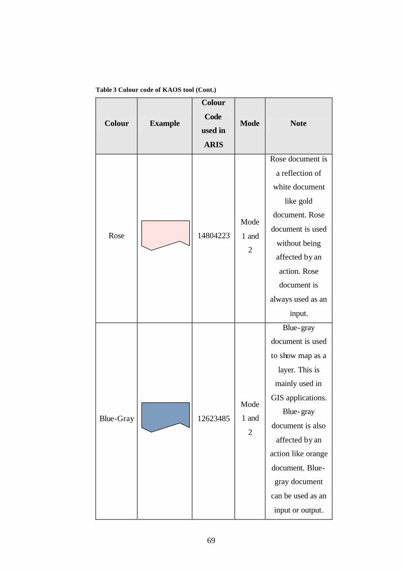
69
Table 3 Colour code of KAOS tool (Cont.)
Colour Example
Colour
Code
used in
ARIS
Mode Note
Rose
14804223
Mode
1 and
2
Rose document is
a reflection of
white document
like gold
document. Rose
document is used
without being
affected by an
action. Rose
document is
always used as an
input.
Blue-Gray
12623485
Mode
1 and
2
Blue-gray
document is used
to show map as a
layer. This is
mainly used in
GIS applications.
Blue-gray
document is also
affected by an
action like orange
document. Blue-
gray document
can be used as an
input or output.

70
Table 3 Colour code of KAOS tool (Cont.)
Colour Example
Colour
Code
used in
ARIS
Mode Note
Light
Turquoise
16777152
Mode
1 and
2
Light turquoise
document is a
reflection of blue-
gray document
like gold
document. Light
turquoise
document is used
without being
affected by an
action. Light
turquoise
document is
always used as an
input.
Pale Blue
15658671 Mode
2
Pale blue
document is used
when light
turquoise
document is
necessary to be
used at Mode 2.
The properties of
light turquoise
document are also
valid for pale blue
document.

71
Table 3 Colour code of KAOS tool (Cont.)
Colour Example
Colour
Code
used in
ARIS
Mode Note
Teal
9143144 Mode
2
Teal document is
used when blue-
gray document is
necessary to be
used at Mode 2.
The properties of
blue-gray
document are
valid for teal
document.
Lavender
13353215 Mode
2
Lavender
document is used
when gold
document is
necessary to be
used at Mode 2.
The properties of
gold document
are also valid for
lavender
document.

72
Table 3 Colour code of KAOS tool (Cont.)
Colour Example
Colour
Code
used in
ARIS
Mode Note
Red
255 Mode
2
Red document is
used when light
orange document
is necessary to be
used at Mode 2.
The properties of
light orange
document are also
valid for red
document.
If an object needs to be used in a requirement, it should be connected with
the relevant object.
If requirements are filtered according to an application system type name
during generation, the keyword for filtering is sufficient for the generation. For
example, if the name of an application system type is “GIS System” and there is
no application system type name consisting of “GIS”, then it is enough to choose
“GIS” as a keyword for filtering operation.
3.3.2.1. Naming Constraints
• An object name should conform to following abbreviation and
spelling rules.
• All abbreviations should be ended with a dot.
• While naming objects, one space should be left between the words.
On the other hand, if a name consists of more than one word and
there is a need to write the name on more than one line, no space
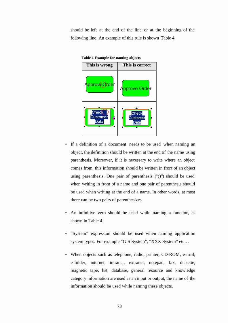
73
should be left at the end of the line or at the beginning of the
following line. An example of this rule is shown Table 4.
Table 4 Example for naming objects
This is wrong This is correct
ApproveOrder
Approve Order
• If a definition of a document needs to be used when naming an
object, the definition should be written at the end of the name using
parenthesis. Moreover, if it is necessary to write where an object
comes from, this information should be written in front of an object
using parenthesis. One pair of parenthesis (“()”) should be used
when writing in front of a name and one pair of parenthesis should
be used when writing at the end of a name. In other words, at most
there can be two pairs of parenthesizes.
• An infinitive verb should be used while naming a function, as
shown in Table 4.
• “System” expression should be used when naming application
system types. For example “GIS System”, “XXX System” etc…
• When objects such as telephone, radio, printer, CD-ROM, e-mail,
e-folder, internet, intranet, extranet, notepad, fax, diskette,
magnetic tape, list, database, general resource and knowledge
category information are used as an input or output, the name of the
information should be used while naming these objects.

74
• If one or more of the following: mobile phone, telephone, CD-
Rom, diskette, magnetic type, database, file, electronic folder,
electronic document, e-mail, internet, extranet, intranet, knowledge
category, general resource, printer, book, list and notepad are
connected with the function as an output where a document or
documents are not connected with that function as an output, the
function should not be named.
3.4. Sentence Structure
Although the definition of a requirement is clearly stated, neither the
components of a requirement sentence are explicitly defined nor are defined
sentences the same due to the nature of the requirement sentence. There is an
explicit process to be followed to determine sentence construct and type is
explained below.
First, the guidelines and the characteristics such as “well-written” and “well-
structured” that a requirements sentence should have, which were mentioned in
chapter 2, are identified so that this information is considered while sentences
structures are being formed. Then, at least the constructs are determined according
to common properties to form sentence structures from the descriptions of the
components of a requirement sentence. These common constructs can also be
called “base components” because additional components can be added according
to case specific situations.
The identified base components are:
• Actor(s) such as people, system etc.…
• An action such as read, write etc.…
• Input(s) such as information carrier (if exists)
• Output(s) such as message (if exists)
Secondly, the software functional requirements of a military project which
is similar to the experimental study is chosen to clarify the case specific needs of

75
sentences and also the constraints. The requirements of a similar project are
classified according to its base components, while specific needs are identified so
that the dynamic and the static constructs of a requirement sentence are defined
accordingly.
Thirdly, the needs of the project which is chosen for an experimental study
are determined together with tool restrictions. Although assumptions, rules and
notation are predefined, they are broadened to their final state during experimental
study. Possible information carriers are determined and added for the purpose of
general usage of the tool.
There are three dynamic sentence constructs for input and two dynamic
constructs for output. Moreover, there are seven dynamic constructs for other
purposes such as suffix, position, application system type and user interface. To
ease coding a special abbreviation is applied when naming main dynamic
sentence constructs. These are explained in Table 5
Table 5 Description of main dynamic sentence constructs
Main Dynamic Construct Name Description
g_sActInCarHS
g = Global s = String Act = Active InCar = Information Carrier HS = Harita Son (Map End)
g_sActInCarMS
g = Global s = String Act = Active InCar = Information Carrier MS = Metin Son (Text End)
g_sPasInCarNHS
g = Global s = String Pas = Passive InCar = Information Carrier N = Nesne (Object) HS = Harita Son (Map End)
g_sPasInCarNMS
g = Global s = String Pas = Passive InCar = Information Carrier N = Nesne (Object) MS = Metin Son (Text End)

76
Table 5 Description of main dynamic sentence constructs (Cont.)
Main Dynamic Construct Name Description
g_sPasPS
g = Global s = String Pas = Passive P = Position
g_sPasASTS
g = Global s = String Pas = Passive ASTS = Application System Type Son (Application System Type End)
g_sPasInCarNDS
g = Global s = String Pas = Passive InCar = Information Carrier NDS = Nesne Degil Son (Not Object End)
g_sProcIn g = Global s = String ProcIn = Process Interface
The components of a requirement sentence and the description of the
suffixes used are shown in Table 6 and Table 7 respectively.
Table 6 Main constructs of sentence structures
Construct Name Description Applied Processes
g_sActInCarHS
This is a last state of
output objects used to
show a map as a layer.
They are represented by
blue-gray documents or
teal document symbols in
models and are also
affected by an action
during a process
execution.
Required suffix
added to the words
which finish with
“i”, “i”, “e”, “a”,
“u”, “er”, “ar”.
“,” and/or “and”
are added
according to
number of the
outputs.

77
Table 6 Main constructs of sentence structures (Cont.)
Construct Name Description Applied Processes
g_sActInCarMS
This is a last state of
output information
carriers other than blue-
gray and teal documents
such as white document,
light orange document,
red document and other
information carriers
which can be used as an
output. They are affected
by an action during a
process execution.
Required suffix
added to the words
which finish with
“i”, “i”, “e”, “a”,
“u”, “er”, “ar”.
Used information
carriers other than
document type are
added.
“,” and/or “and”
are added
according to
number of the
outputs.
g_sPasInCarNHS
This is a last state of the
input objects which are
used to show a map as a
layer. They are
represented by blue-gray
documents or teal
document symbols in
models and are also
affected from an action
during a process
execution.
Required suffix
added to the words
which finish with
“i”, “i”, “e”, “a”,
“u”, “er”, “ar”.
“,” and/or “and”
are added
according to
number of the
inputs.

78
Table 6 Main constructs of sentence structures (Cont.)
Construct Name Description Applied Processes
g_sPasInCarNMS
This is the last state of
input information carriers
other than blue-gray and
teal documents such as
white document, light
orange document, red
document and other
information carriers
which can be used as an
output. They are affected
by an action during a
process execution.
Required suffix
added to the words
which finish with
“i”, “i”, “e”, “a”,
“u”, “er”, “ar”.
“,” and/or “and”
are added
according to
number of the
inputs.
g_sPasPS
This is the last state of
roles. They are
represented by
organizational units,
positions, or group
symbols. They execute
an action.
Required suffix
added to the words
which finish with
“k”, “d”, “b”.
“,” and/or “and”
are added
according to
number of the
inputs.
g_sPasASTS
This is the last state of
application system types.
They are represented by
an application system
type symbol.
The suffix “nde”
added to a word.
“,” and/or “and”
are added
according to
number of the
inputs.
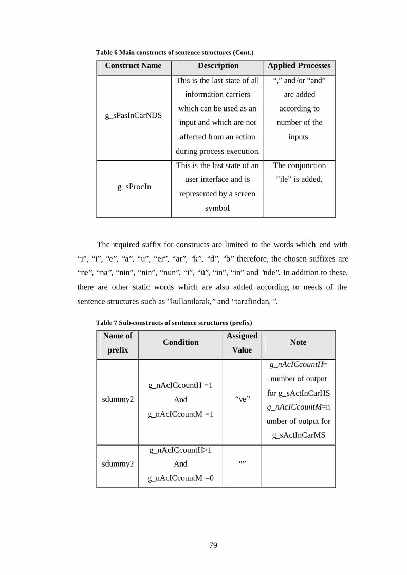
79
Table 6 Main constructs of sentence structures (Cont.)
Construct Name Description Applied Processes
g_sPasInCarNDS
This is the last state of all
information carriers
which can be used as an
input and which are not
affected from an action
during process execution.
“,” and/or “and”
are added
according to
number of the
inputs.
g_sProcIn
This is the last state of an
user interface and is
represented by a screen
symbol.
The conjunction
“ile” is added.
The required suffix for constructs are limited to the words which end with
“i”, “i”, “e”, “a”, “u”, “er”, “ar”, “k”, “d”, “b” therefore, the chosen suffixes are
“ne”, “na”, “nin”, “nin”, “nun”, “i”, “ü”, “in”, “in” and "nde". In addition to these,
there are other static words which are also added according to needs of the
sentence structures such as "kullanilarak,” and “tarafindan, ".
Table 7 Sub-constructs of sentence structures (prefix)
Name of
prefix Condition
Assigned
Value Note
sdummy2
g_nAcICcountH =1
And
g_nAcICcountM =1
“ve”
g_nAcICcountH=
number of output
for g_sActInCarHS
g_nAcICcountM=n
umber of output for
g_sActInCarMS
sdummy2
g_nAcICcountH>1
And
g_nAcICcountM =0
“”

80
Table 7 Sub-constructs of sentence structures (prefix) (Cont.)
Name of
prefix Condition
Assigned
Value Note
sdummy2
g_nAcICcountH=1
And
g_nAcICcountM =0
“”
sdummy2
g_nAcICcountH=0
And
g_nAcICcountM =1
“”
sdummy2
g_nAcICcountH=0
And
g_nAcICcountM >1
“”
sdummy2
g_nAcICcountH>1
And
g_nAcICcountM >1
“,”
sdummy2
g_nAcICcountH>1
And
g_nAcICcountM =1
“ve”
sdummy2
g_nAcICcountH =1
And
g_nAcICcountM >1
“,”
sdummy2
g_nAcICcountH =0
And
g_nAcICcountM =0
“”
sdummy7
g_nAcICcountH =1
And
g_nAcICcountM =1
“,”
sdummy7
g_nAcICcountH>1
And
g_nAcICcountM =0
“,”
sdummy7
g_nAcICcountH=1
And
g_nAcICcountM =0
“ve”
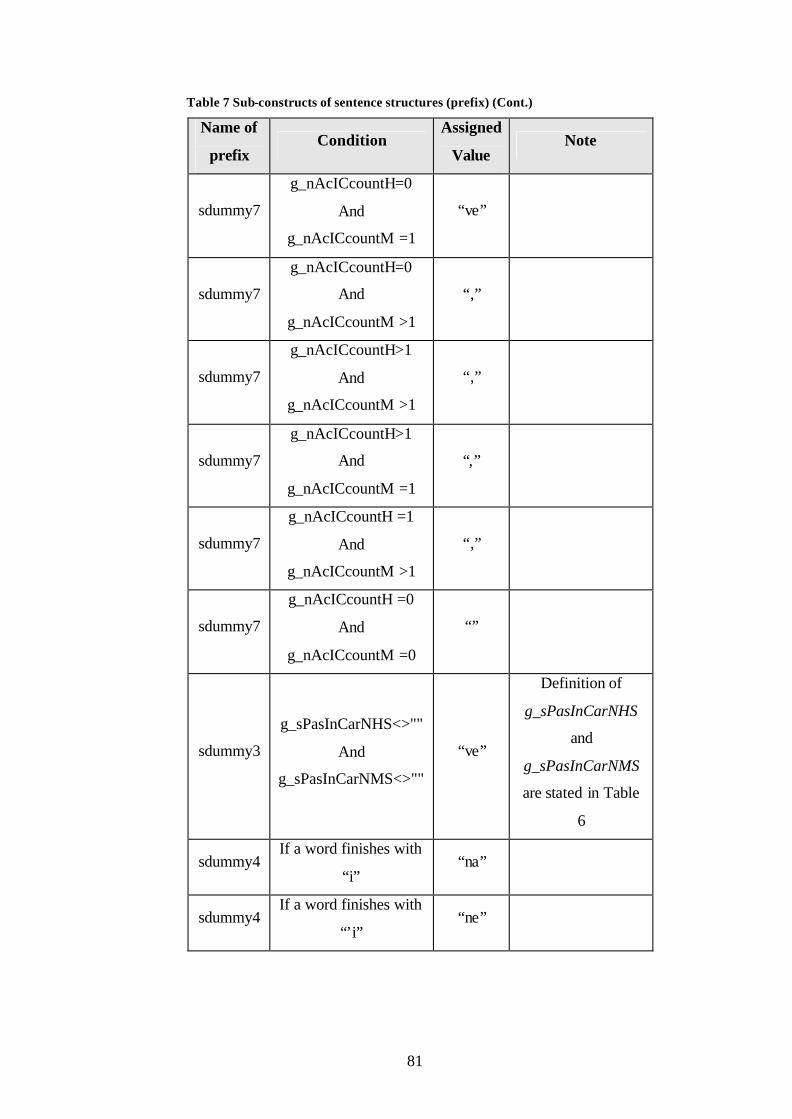
81
Table 7 Sub-constructs of sentence structures (prefix) (Cont.)
Name of
prefix Condition
Assigned
Value Note
sdummy7
g_nAcICcountH=0
And
g_nAcICcountM =1
“ve”
sdummy7
g_nAcICcountH=0
And
g_nAcICcountM >1
“,”
sdummy7
g_nAcICcountH>1
And
g_nAcICcountM >1
“,”
sdummy7
g_nAcICcountH>1
And
g_nAcICcountM =1
“,”
sdummy7
g_nAcICcountH =1
And
g_nAcICcountM >1
“,”
sdummy7
g_nAcICcountH =0
And
g_nAcICcountM =0
“”
sdummy3
g_sPasInCarNHS<>""
And
g_sPasInCarNMS<>""
“ve”
Definition of
g_sPasInCarNHS
and
g_sPasInCarNMS
are stated in Table
6
sdummy4 If a word finishes with
“i” “na”
sdummy4 If a word finishes with
“’i” “ne”

82
Table 7 Sub-constructs of sentence structures (prefix) (Cont.)
Name of
prefix Condition
Assigned
Value Note
sdummy5
g_nAcICcountH>0
Or
g_nAcICcountM>0
"olusturu
lmasina"
sdummy5
g_nAcICcountH=0
And
g_nAcICcountM=0
And
g_sActInCarMS<>""
“”
Definition of
g_sActInCarMS is
stated in Table 6.
sdummy5
g_sActInCarHS=""
And
g_sActInCarMS=""
Definition of
g_sActInCarHS is
stated Table 6.
The data gathered from the processes stated above is used to form the final
sentence structures of the tool. There are two kinds of sentence structure used in
the tool which are as follows:
Sentence Structure 1
Application System Type + Input (1) + Position + User Interface + Output
(1) + sdummy2 + Output (2) + Function + sdummy4 + " olanak saglamalidir."
g_sPasASTS + g_sPasInCarNDS +g_sPasPS + g_sProcIn + g_sActInCarHS
+sdummy2+g_sActInCarMS+" "+scurrentfuname+sdummy4+" olanak
saglamalidir."
Sentence Structure 2
Application System Type+input(1)+Input(2)+sdummy3+ Input(3)+
Position+User
Interface+Function+sdummy4+sdummy7+Output(1)+sdummy2+Output(2)+
sdummy5 +" olanak saglamalidir."

83
g_sPasASTS+g_sPasInCarNDS+g_sPasInCarNHS+sdummy3+g_sPasInCar
NMS+g_sPasPS+g_sProcIn+scurrentfuname+sdummy4+sdummy7+g_sActInCar
HS+ sdummy2+g_sActInCarMS+sdummy5+" olanak saglamalidir."
The selection of sentence structures is closely linked with the input data. For
example, if input data is affected by an action, sentence structure 2 is used. In
other words, if a colour of an input object is white, light orange, red, blue-gray or
teal, the sentence type is chosen as sentence structure 2. If all the input data is not
affected by an action, sentence structure 1 is chosen.
If requirements are generated by using the filtering option, an application
system name is removed from the sentence structures. The functional
requirements of the business process are generated by using the sentence
components dynamically within sentence structures.
3.4.1. Example sentences
An example eEPC model shown in Figure 14 is used to generate functional
requirements. The model is evaluated twice by the tool to show the effect of the
filtering option. If requirements are generated according to a specific application a
system type filtering option is chosen. In other words, if all requirements of the
application system types are generated together, the filtering option is not chosen.
The relevant requirements sentence are given in section 3.4.1.1.

84
kullanici arayüzü
Evrak yönetimsistemi
Yeni Ögrenci Kabul Edildi
hazirlanmasi
1
Ögrenci kabul listesi
Ögrenci bilgileri
kopyalanmasi
2
Ögrenci resmi
hazirlanmasi
3
Ögrenci resmi
ögrenci dosyasi
HocaListesi
Bölüm sekreteri
Ögrenci bilgileri
Bölüm sekreteri
Bölüm sekreteri
Ögrenci Kayit Edildi
Figure 14 Example eEPC for requirement sentences
3.4.1.1. Examples for Generated Functional Requirements with a
Filtering Option
In Figure 14, Function 1 has two inputs one of which is affected by an
action whereas the other is not. Function 1 also has one output that is affected by
an action, one organizational unit, one user interface and application system type.
Sentence structure 2 is chosen because one of the inputs is affected by an action.
The result requirement sentence for function 1 is:
Hoca Listesi kullanilarak Ögrenci kabul listesi'nin, Bölüm sekreteri
tarafindan, kullanici arayüzü ile hazirlanmasina ve Ögrenci bilgileri'nin
olusturulmasina olanak saglamalidir.

85
Function 2 has one input which is affected by an action, 1 output which is
affected by an action, one organizational unit, one user interface and application
system type. Sentence structure 2 is chosen because the input is affected by an
action.
The resulting requirement sentence for function 2 is:
Ögrenci resmi'nin, Bölüm sekreteri tarafindan, kullanici arayüzü ile
kopyalanmasina olanak saglamalidir.
Function 3 has two inputs which are not affected by an action, one output
that is affected by an action, one organizational unit, one user interface and
application system type. Sentence structure 1 is chosen because there is no any
input affected by an action.
The resulting requirement sentence for function 3 is:
Ögrenci resmi ve Ögrenci bilgileri kullanilarak Bölüm sekreteri tarafindan,
kullanici arayüzü ile ögrenci dosyasi'nin hazirlanmasina olanak saglamalidir.
3.4.1.2. Examples for Generated Functional Requirements without a
Filtering Option
The application system type name is added when filtering is not applied
during generation.
Evrak yönetim sisteminde, Ögrenci kabul listesi ve Hoca Listesi kullanilarak
Bölüm sekreteri tarafindan, kullanici arayüzü ile Ögrenci bilgileri'nin
hazirlanmasina olanak saglamalidir.
Evrak yönetim sisteminde, Ögrenci resmi'nin, Bölüm sekreteri tarafindan,
kullanici arayüzü ile Kopyalanamsina olanak saglamalidir.
Evrak yönetim sisteminde, Ögrenci bilgileri ve Ögrenci resmi kullanilarak
Bölüm sekreteri tarafindan, kullanici arayüzü ile ögrenci dosyasi'nin
hazirlanmasina olanak saglamalidir.

86
CHAPTER 4
4. EXPERIMENTAL STUDY
This chapter describes the details of the experimental study. The main aim
of the experimental study was to validate the tool execution. Other aims of the
experimental study were to measure the effectiveness of the tool and discover if
there were other benefits of the tool.
The experimental study was the project which lasted 13 months and
consists of the technical specification preparation phase of a IS procurement
project for the Turkish Land Forces Command. The process described in the
following sections was applied completely and the tool was successfully used
during the study. Due to the sake of secrecy and security, the process followed,
the size of the project, the structure of the project office and the results of tool
executions are explained but other details are can not be revealed.
The following sections include a description of the experimental study, the
context of the experimental study which is applied during experimental study and
application of the KAOS tool.
4.1. Description of Experimental Study
The resultant size of the experimental study (the system) was 26930 FP. The
system consisted of 295 business process models and contained 1270 functions.
There were 2913 information carriers and 74 organizational units connected with
functions.

87
The project team consisted of two sub-teams one of which was the Middle
East Technical University (METU) project team and the other the customer side
project team, as shown in Figure 15. The METU project team consisted of a
software and hardware analysis group. The customer’s project team included
domain experts which were changed when the domain changed.
The Project Team
METUProject Team
The Project Office ofthe Customer
HardwareAnalysis
Team
SoftwareAnalysis
Team
Domain Experts
Figure 15 The structure of the team
4.2. The Context of the Experimental Study
The recommended and also applied processes consist of seven main sub-
processes which includes; concept exploration, AS-IS business process modelling,
TO-BE business process modelling, system requirement specification,
verifications of the work products and validations of the work products. The
uppermost process is shown in Figure 16.

88
User-Level System RequirementsSpecified
RFP Preparation ProjectContracted
As-Is BPMVerification
and ValidationCompleted
Are As-Is BPMsverified and validated?
Are To-Be BPMsverified and validated?
Are system requirementsverified and validated?
System Requirements
System Requirements(approved)
To-Be BusinessProcess Modeling
Completed
Concept Documents(books, instructions, forms, reports)
Concept Exploration
As-IsBusiness Process Modelling
To-BeBusiness Process Modelling
System RequirementsSpecification
As-Is BPMVerification and Validation
To-Be BPMVerification and Validation
Identifying key stakeholders, user representatives,domain documents, legacy documents (if any);
Arranging orientation meetings
As-IsBusiness Process Models
As-IsBusiness Process Models
(approved)
No
To-BeBusiness Process Models
NoTo-Be
Business Process Models(approved)
System RequirementsVerification and Validation
Concept ExplorationCompleted
No
Yes
SoftwareAnalysis
Team
As-Is BusinessProcess Modeling
Completed
System RequirementsSpecified
Yes
To-Be BPMVerification
and ValidationComplited
Domain Experts
Figure 16 The uppermost process in eEPC

89
4.2.1. Concept Explorations
Concept exploration is the first activity in the process, as shown in Figure
16. It starts when the RFP preparation project is contracted. The aim of this phase
is to identify key stakeholders, user representatives, domain documents and legacy
documents (if any). In addition, orientation meetings are arranged with customer.
Concept exploration is realized by the software analysis team.
4.2.2. AS-IS Business Process Modelling
AS-IS business process modelling is the second activity in the uppermost
process and details of the activity are shown in Figure 17. The fundamental aim
of the process is to visualise current business processes. AS-IS business process
modelling is realized by 6 sub-steps. These are identifying organizational charts
for business domain, identifying key business processes for each organizational
unit, decomposing and modelling key business processes into sub business
processes, modelling each lowest- level sub-business process, creating data
dictionary, and verification and validation of AS-IS data dictionary.
AS-IS business process modelling activity is triggered when the concept
exploration is completed. First, organizational charts are identified and then key
business processes for each organizational unit are identified. Key business
processes are decomposed and modelled into sub business processes until the
lowest possible level for modelling is reached. These steps are carried out by the
software analysis team and domain experts.
Meanwhile, the data dictionary of the AS-IS model is created by the
software analysis team during the AS-IS modelling. When the data dictionary is
completed, verification and validation of AS-IS data dictionary (AS-IS DD) is
done by domain experts. If there are any mistakes in the AS-IS DD, it is updated
by software analysis team. Updating operations continue until the AS-IS DD is
verified and validated. When the AS-IS DD is prepared and the modelling of all
sub processes are finished, the work product of this activity, the AS-IS business
process models, are produced.

90
Identifying Organizational Chartsfor Business Domain
Identifying Key Business Processesfor Each Organizational Unit
Yes Is data dicitonaryis verified and validated?
Domain Experts
Updating DataDictionary
No
SoftwareAnalysisTeam
SoftwareAnalysis
Team
Decomposing and ModellingKey Business Processes
Into Sub Business Processes
SoftwareAnalysisTeam
Modelling Each Lowest-LevelSub Business Process
YesNo
Is decomposed model atappropriate level of detail?
As-IsData Dictionary
CreatingData Dictionary
Verification and Validation ofAs-Is Data Dictionary
As-IsData Dictionary
(approved)
As-Is Data DictionaryPrepared
Concept ExplorationCompleted
Concept Documents(books, instructions, forms, reports)
Modeling Each Lowest-LevelSub Business Process
Completed
As-Is BusinessProcess Modeling
Completed
Domain Experts
Figure 17 AS-IS BPM
4.2.3. AS-IS BPM Verification and Validation
The AS-IS business process model (BPM) verification and validation is the
third activity in the uppermost process, as shown in Figure 16. The activity starts
when the AS-IS business process modelling is completed.
The fundamental aim of the process is to verify and validate AS-IS models.
Domain experts inspect AS-IS business process models comparing business
processes with models for verification and validation. When there is conflict in
the fit between business processes and models, models are updated by domain
experts and the software analysis team. This is a recursive action and continues
until all models are verified and validated.

91
4.2.4. TO-BE Business Process Modelling
TO-BE business process modelling is the fourth activity in the uppermost
process and details of the activity are shown in Figure 18-a and Figure 18-b. The
fundamental aim of the process is to model target business processes and
determine IT support for the target business processes. TO-BE process modelling
activity is realized by 15 sub-steps including analyzing and enhancing existing
business processes, verification and validation enhanced BPMs, identifying
business processes that need IT support, identifying high- level software
components, assigning software components to business processes that need it
support, verification and validation of software components assigned to BPMs,
identifying hardware components, validation of hardware components, assigning
software components to hardware components, identifying data transmission
requirements, identifying telecommunication infrastructure, validation of
telecommunication infrastructure, identifying system architecture, updating data
dictionary and verification and validation of to-be data dictionary.
The TO-BE BPM activity is triggered when the AS-IS BPM verification and
validation are completed. First, taking into account the tool restriction, the AS-IS
business processes are analyzed and enhanced by software analysis team and
where possible domain experts. Enhanced business process models are verified
and validated by domain experts. When enhanced business process models are not
verified and/or not validated, updates continue until all models are verified and
validated. Later, business processes which need IT support are identified by the
software analysis team and domain experts while each high level component is
identified by software analysis team. There is a close interaction between these
identifications because both sides affect each other. When both identifications are
completed, determined high- level software components are assigned to the
business processes that need IT support. The work products of the activity are the
software components assigned business process models and these are verified and
validated before proceeding to the next activity. If there is a problem for the work
product, updates are applied where appropriate by the software analysis team and
domain experts. This is a recursive action and continues until verification and
validation is completed. The following step is hardware component identification
and is completed by the hardware analysis team. The software components are

92
used to determine hardware components. The hardware components are then
validated by domain experts. If validation is not realized, the determined hardware
components are updated until the validity is approved. Approved software
components are assigned to approved hardware components by software and
hardware analysis team, meanwhile data transmission requirements are identified
by hardware analysis team and domain experts. Telecommunication infrastructure
is identified by the hardware analysis team and domain experts as soon as data
transmission requirements are identified. Telecommunication infrastructures are
then validated by domain experts. Updates continue until validity is approved.
When software components are assigned and the validation of telecommunication
infrastructure is supplied, system architecture is identified by hardware analysis
team using approved telecommunication infrastructure and software components.
The data dictionary is updated by software analysis team while the activities
of TO-BE business process modelling are realized. Verification and validation of
data dictionary is achieved by domain experts when updates are completed.
Update operation continues until verification and validation are completed.
TO-BE business process modelling is completed, after the system
architecture has been determined and TO-BE data dictionary has been prepared.
The work product of this process is the TO-BE BPMs.

93
As-IsBusiness Process Models
(approved)
Identifying high-levelsoftware components
Domain Experts
Domain Experts
Domain Experts
Domain Experts
Software components assignedbusiness process models
Verification and Validation ofSoftware components assigned
to BPMsSoftware componentsassigned business
process models(approved)
Updating DataDictionary
Analyzing andenhancing
existingbusiness processes
Verification and ValidationEnhanced BPMs
No
EnhancedBusiness
Process Models
EnhancedBusiness
Process Models(approved)
EnhancedBusiness
Process Models(approved)
Identifyingbusiness processesthat need IT support
Assigningsoftware components
to businessprocesses thatneed IT support
EnhancedBusiness
Process Models(approved)
Yes
High-LevelSoftware Components
To-BeData Dictionary
As-IsData Dictionary
Verification and Validation ofTo-Be Data Dictionary
To-BeData Dictionary
(approved)
To-BeData Dictionary
Prepared
As-Is BPMVerification
and ValidationCompleted
SoftwareAnalysis
Team
Are BPMsVerified and Validated?
Yes
NoNo
Are software componentassigned to BPMs,identified high-level
software component andidentified business processes
that need IT supportare verified and validated?
No
Yes
Is To-Bedata dictionary
validated?
SoftwareAnalysis
Team
SoftwareAnalysis
Team
SoftwareAnalysis
Team
Domain Experts
Figure 18-a TO-BE BPM

94
Domain Experts
Domain Experts
Identifyinghardware components
HardwareAnalysis
Team
Identifying telecommunicationinfrastructure
Assigning softwarecomponents to
hardwarecomponents
Hardware Components
Validation ofHardware Components
Validation oftelecommunication
infrastructure
SystemArchitecture
Identifying system architecture
TelecommunicationInfrastructure
SoftwareComponents assignedHardware Components
Software componentsassigned business
process models(approved)
Hardware Components(approved)
Identifying datatransmissionrequirements
To-BeData Dictionary
Software componentsassigned business
process models(approved)
TelecommunicationInfrastructure
(approved)
System ArchitectureIs Identified
To-Be BusinessProcess Modeling
Completed
No
Yes
Are hardwarecomponentsvalidated?
Yes
No
Istelecommunication
infrastructurevalidated?
HardwareAnalysis
Team
HardwareAnalysis
Team
SoftwareAnalysis
Team
HardwareAnalysis
Team
Figure 18-b TO-BE BPM
4.2.5. TO-BE BPM Verification and Validation
TO-BE BPM verification and validation is the fifth activity in the uppermost
process, as shown in Figure 16. The activity starts after the TO-BE business
process modelling is completed.

95
The fundamental aim of the process is to verify and validate TO-BE BPMs
and the activity completed by domain experts. When there is a problem in the TO-
BE BPMs, updates are carried where necessary.
4.2.6. System Requirement Specification
System Requirement Specification is the fifth activity in the uppermost
process and details of the activity are shown in Figures 19-a, 19-b. The
fundamental aim of the process is to generate the system requirements of the TO-
BE business process models. The system requirements specification activity is
realized by 11 sub-steps such as automated user- level functional system
requirements generation, verification and validation of user-level functional
system requirements allocated to software, identifying Commercial Off The Shelf
(COTS) requirements, identifying non-functional system requirements, integrating
system requirements allocated to software, verification and validation of system
requirements allocated to software, preparing system WBS, verification and
validation of system WBS, specifying hardware and telecommunication
infrastructure requirements, verification and validation of system requirements
allocated to hardware and telecom infrastructure, integration of software,
hardware, and telecommunication requirements specifications.
The system requirement specification activity is triggered as soon as TO-BE
BPM verification and validation is completed. First, user level functional system
requirements are generated by the tool using the work products which are the
software components assigned business process models (approved). Since one of
the aims of the experimental study was to test the tool, this is one of the important
parts of the whole process. When generation is completed, verification and
validation activities for user-level functional system requirements allocated to
software are applied by domain experts. The activities continue until the user-
level functional system requirements allocated to software are validated. If there is
any problem concerning the requirements, due to models, the required changes are
done.
Meanwhile COTS requirements and non-functional requirements are
identified by the software and hardware analysis team. Then, the identified

96
requirements and validated requirements are integrated by the software analysis
team to form system requirements allocated to software. Afterwards, system
requirements allocated to software are verified and validated by the domain
experts. When there is any problem concerning requirements, there root activity
from where problems emanate is repeated until system requirements allocated to
software are verified and validated. Later, the system Work Breakdown Structure
(WBS) is prepared by the hardware analysis team. Domain experts inspect the
system WBS for verification and to validation. If there is a problem about the
system WBS, the system WBS is updated by the hardware analysis team until
system WBS is verified and validated. Next, hardware and telecommunication
infrastructure is specified by the hardware analysis team and system requirements
allocated to hardware and telecommunication infrastructure are produced via the
activity. Verification and validation of system requirements allocated to hardware
and telecom infrastructure are sequential steps and carried out by domain experts.
These requirements are updated until they are verified and validated by the
customer. The final activity of the system requirement specification is the
integration of hardware, software and telecommunication requirements. This
activity is completed by hardware and software analysis team and the work
product of this stage is system requirements.

97
AutomatedUser-Level FunctionalSystem Requirements
Generation
IdentifyingNon-Functional
SystemRequirements
Domain Experts
KAOS Script
No
Yes
Are User-Levelfunctional system
requirementsallocated to software
verified and validated?
Yes
NoNoAre identified COTS
requirements,identified non-functional
requirements,and the result of integration
opeationverified and validated?
As-Is BPMVerification
and ValidationCompleted
User-LevelFunctional System
RequirementsAllocated to Software
Software componentsassigned business
process models(approved)
IdentifyingCOTS
Requirements
Integrating SystemRequirements
Allocatedto Software
Non-FunctionalSystem
Requirements
Non-FunctionalSystem
Requirements
COTSRequirements
System RequirementsAllocated to Software
Verification and Validation ofSystem RequirementsAllocated to Software
System RequirementsAllocated to Software
(approved)
HardwareAnalysis
Team
SoftwareAnalysisTeam
COTSRequirements
User-LevelFunctional System
RequirementsAllocated to Software
(validated)
User-LevelFunctional System
RequirementsAllocated to Software
(validated)
Verificationand Validation of
User-LevelFn. Sys. Req.sAllocated to Sw
To-Be BPMVerification
and ValidationComplited
Domain Experts
Figure 19-a System requirement s pecification

98
Domain Experts
Yes
No
Are system WBSverified an validated?
Yes
No
Are system requirementsallocated to hardware and
telecommunication infrastructureverified and validated?
Verification andValidation ofSystem WBSSystem WBS
(approved)
System RequirementsAllocated to Hardware and
Telecommunication Infrastructure
Verific. and Valid. ofSys. Req.s
Allocated to Hw andTelecom.
Infrastructure
Sys. Req.sAllocated to Hw and
Telecomm. Infrastructure(approved)
Integration of Sw, Hw, andTelecommunication Req.s
Specifications
SpecifyingHardware and Telecommunication
Infrastructure Requirements
PreparingSystem WBS
System RequirementsAllocated to Software
(approved)
System WBSSystem
Architecture
System Requirements
System RequirementsSpecified
HardwareAnalysis
Team
HardwareAnalysis
Team
SoftwareAnalysisTeam
Domain Experts
Figure 19-b System requirements specification
4.2.7. System Requirement Verification and Validation
System Requirement Verification and Validation is the sixth and the last
activity in the uppermost process, as shown in Figure 16. The activity starts as
soon as system requirements are specified
The fundamental aim of the activity is to verify and validate integrated
system requirements. Domain experts are responsible for this activity and if

99
missing items are found in the end of inspections, relevant activities and processes
repeated until the system requirements are verified and validated otherwise the
uppermost process is completed successfully with the work product being the
approved system requirements.
4.3. Application of the KAOS Tool
The process which is shown in Figure 16 is followed in its entirety. 295
business process models are instantiated by the KAOS tool and 1270 functional
requirements were generated. The generation took 303 minutes although there are
many complicated connections among rules, event and functions. Each function of
the models are compared with the related requirements sentences to check
whether requirements sentences are formed correctly and to find out whether there
is any function which has not been evaluated by the tool during generation
Results show that 753 generated requirements did not necessitate any
correction. In other words, 59.3% of generated requirements did not contain
punctuation errors, spelling errors, inconsistencies or badly structured sentences.
On the other hand 517 generated requirements (40.7 % of generated requirements)
required corrections and they were corrected in 3 person/days. Applied
corrections can be classified in 2 groups as depicted in Table 8.
Table 8 Reasons of corrections
Reasons of Corrections
Number of
corrected
requirements
Business process models which do not
conform to tool restrictions. 240
Lack of morphological generator 277
Business Process Models which do not conform to tool restrictions and
rules:
240 requirements sentences could not be generated correctly because related
models were not developed considering the tool restrictions.
3 The computer which is used for generation is Pentium 4 – 1.8 GHz / 520 KB RAM

100
• 235 of the 240 requirements contained more than 2 pairs of
parenthesis in the information carriers. For example, one of the
information carriers named “(…Madde 2.(a).(3).(ç))” which
contains 4 pairs of parenthesis. Should be “(…Madde 2.a.3.ç)”
• 2 of the 240 requirements lacked of information carriers because
they were not connected with related functions.
• 3 of the 240 requirements were not right because some information
carriers were not correctly colour coded. In other words, defined
colour codes which are stated in Table 5 (see section 3.3.2 for
detailed information) have not been chosen for information carriers
during the modelling.
Lack of morphological generators:
277 generated requirements sentences were affected by a lack of a natural
language generation modules in KAOS tool.
• Suitable suffixes were added by the tool for the words which end
with “i”, “i”, “e”, “a”, “u”, “er”, “ar”, “k”, “d”, “b” whereas other
words lacked for suffixes so 146 of generated requirement
sentences required suffixes for words which were not considered.
• 93 of 277 requirements sentences required suffixes for information
carriers ending with numbers for example “… Madde 1” which
also required suffixes.
• 12 of 277 requirements sentences were mismatched due to vowel
deletion. For example if an information carrier ended with “Emir”,
one of the possible suffixes for the word is “in” but combining
them as “Emirin” is incorrect. The vowel “i” should be deleted and
word should be constructed as “Emrin”. This is not supported by
the KAOS tool.
• 24 of 277 requirements sentences were affected by softening. For
example one of the possible suffixes for words like “Kitap” is “i”

101
but combining them like “Kitapi” is incorrect. The consonant “p”
should soften as “b” so that words should be construc ted as
“Kitabi”. This is not supported by the KAOS tool.

102
CHAPTER 5
5. CONCLUSION
The main aim of the thesis was to develop a tool to automatically generate
functional requirements in natural language from business processes. Business
process modelling is used as an approach for eliciting requirements. This chapter
concludes the thesis by summarizing the studies performed during the thesis,
describes contributions of the tool and future work.
5.1. Summary
With a related research, description of requirement engineering, the domains
which form requirement engineering and description of requirement are stated.
The classifications of requirements are identified. In addition to these, some of the
characteristics such as “well-written”, “well- identified”, “well-structured” are
clarified for the requirement and requirement sentences. The guideline which is
followed is briefly explained. The requirements which are generated by the tool
KAOS are identified according to the definitions stated for requirements and
requirements sentences. Prominent studies about problems of requirement
engineering industry and their detrimental consequences are mentioned. These
problems are especially important for the thesis because one way of decreasing
the problems directly or indirectly is automatic functional requirement generation.
Business process modelling is briefly explained together with definitions about
business processes and related terminology is stated. The advantages of business
process modelling are also explained from the software engineering point of view.
The ARIS concept and constructs of the ARIS House are explained in detail. EPC
and eEPC modelling method of the ARIS concept is introduced. the notation of

103
the method and the objects which are used in the notation are explained. The
ARIS tool is briefly explained. The classification of the tools which are used for
requirement engineering is explained and the place of the KAOS tool is identified
according to the classification. In addition, the literature survey about automatic
requirement generation tools is mentioned and related tools are compared.
The software design of the KAOS tool, the scenario of the tool, tool
restrictions and sentence structure are explained in detail. A sample business
process model is chosen to generate requirements. A detailed description of the
experimental study is given with the processes followed and the results of the
application of the KAOS tool are discussed.
5.2. Contributions
The business process modeling based requirements generation tool, the
KAOS tool, has been developed as a part of this thesis and was tested in a large
military project to assess its usability. The tool generated requirements of 26930
FP experimental study in 30 minutes. In a similar project the manual generation of
10092 FP requirements document took 2 person/months. Requirements are
generated as intended, if models are produced within tool restrictions. There are
some requirements which were discovered not have been produced correctly
either because some functions of TO-BE BPMs are not modelled considering tool
restrictions or some objects are not connected to functions. The rest of the
requirements sentences are affected by lack of a natural language generation
module. Although a morphological generator is lacking, more than half of the
requirements are completely produced and took 3 person/days to check and
update all requirements. If a morphological generator had been integrated into the
KAOS tool, 79.7% of requirements would have be correctly produced for the
experimental study. As a result, automatic requirements generation using KAOS
is more efficient than manual requirement generation.
The KAOS tool is a link between modelling and writing requirements which
does not exist in other requirement engineering tools. The KAOS tool supports
system level requirements engineering activities whereas current software

104
engineering tools mainly focus on software requirements which are a low level
when compared to system level requirements.
Because all requirements are based on a predefined sentence structure, the
readability of all requirements were improved which increased the
understandability of requirements. A consistent requirement document is supplied
as it is automatically generated from business models. In other words, the
inconsistencies which occur due to many engineers working on different parts of
the documents are prevented
Other benefits of using the tool were discovered. Connection mistakes in
business process models were found with the help of the tool although the
influence of the KAOS tool is indirect. If objects are not connected with relevant
function, they are not seen in requirements sentences which make requirements
sentences incorrect. These connection mistakes are identified while comparing
models with relevant requirements sentences.
Software requirements frequently change and these changes can be
annoying, time consuming and error prone in the manual generation sittuation.
Whereas in automatic generation they are constant thus it is easy to estimate the
cost and design a schedule based on rework and documentation.
It can be concluded from the findings that the KAOS tool significantly
reduces the time and effort required for requirements generation and enables the
identification of modelling mistakes. It can be used for large scale projects. The
effort expended on non-value-added tasks such as reworking and documentation
is decreased, and modifiability of the requirements documents is increased. It is
also possible for requirements to be imported into requirements management tools
which have a basic import/export mechanism such as RequisitePro v2002, Caliber
RM 3.0, C.A.R.E 3.0, Catalyze 1.0, CORE 4.0, Cradle 4.0, DOORS 6.0, Envision
5.4.2, IRqA 2.1, Team Trace 2.1. Therefore further tool assistance can be
integrated into development projects easily.
The completeness, consistency, redundancy control was out of the area of
concern of the KAOS tool and thus were not realized.

105
5.3. Future Work
Future work can be described from two points of views; one concerning tool
development, and the other is about improvements to the functionalities of the
tool.
The KAOS tool has a specific behaviour for different modes of operations
thus this behaviour can be generalized. Currently “roles” are used to define
function execution. Other purposes such as “responsible”, “decides on”,
“contributes to”, “must be informed” can be incorporated into the tool and can be
considered during requirement generation. Conditional requirements are not
considered thus conditional sentences can be generated. Requirements are
generated in “.Doc” format but they can also be generated in a more generic
format (such as XML) to improve integration possibilities.
The tool can be improved to generate a responsibility-role matrix.
Morphological generators for Turkish can be integrated into the KAOS tool so
that corrections applied to the requirements sentences can be minimized.

106
REFERENCES
Bayias, P., and Hadzilacos, T., 1999, “The Requirements Engineering Process of ΟΑΣΗΣ: An Industrial Case Study”, http://citeseer.nj.nec.com/cs Berenbach, B., 2003, “The Automated Extraction of Requirements from UML Models”, Proceedings of the 11th IEEE International Requirements Engineering Conference,pp.1. Bray, I.K., 2002, “Requirements Engineering”, Addison Wesley Publishing Company. Brooks, F.P., 1987, “No Silver Bullet-Essence and Accidents of Software Engineering”, Computer Magazine,Vol.20, pp.10-19. Christel, M.G., and Kang, K.C., 1992, “Issues in Requirements Elicitation”, Technical Report, CMU/SEI-92-TR-012. Decker, S., Erdmann, M., and Studer, R., 1996, “A Unifying View on Business Process Modelling and Knowledge Engineering”, Proceedings of the 10th Knowledge Acquisition for Knowledge Based Workshop,pp.1-16. Demirörs, O., Tarhan, A., and Gencel, Ç., 2003, “Utilizing Business Process Models for Requirements Elicitation: A Large System Acquisition Experience”, 29th Euromicro Conference, Vol-2, pp.409-412. Gladwin, B., and Tümay, K., 1994, “Modelling Business Processes with Simulation Tools”, Proceedings of the 1994 Winter Simulation Conference, SCS pp.114-121.

107
Hlupic, V., and Robinson, S., 1998, “Business Process Modelling and Analysis Using Discrete-Event Simulation”, Proceedings of the Winter Simulation Conference, Vol-2, pp.1363-1369. IDS Scheer AG, 2003, “ARIS Framework Concept”, http://www.ids-scheer.com. INCOSE, 2002a, “SE Tools Taxonomy”, http://www.incose.org. INCOSE, 2002b, “Tools Survey: Requirements Management (RM) Tools”, http://www.incose.org. Lausen, S., 2002, “Software Requirements-Styles and Techniques”, Addison Wesley Publishing Company. Lindsay, A., Downs, D., and Lunn, K., 2003, “Business Process-Attempt to Find a Definition”, Information and Software Technology, pp.1015-1019. Loos, P., and Allweyer, T., 1998, “Object-Orientation in Business Process Modelling Through Applying Event Driven Process Chain (EPC) in UML”, IEEE, pp.102-112. Macaulay, L.A., 1996, “Requirements Engineering”, Springer-Verlag. Mattes, F., Wegner, H., and Hupe, P.,1999, “A Process-Oriented Approach to Software Component Definition”, Springer-Verlag, pp.26-40. Robertson, S., and Robertson, J., 1999, “Mastering the Requirements Process”, Addison Wesley Publishing Company. Scheer, A.W., 1994, “Business Process Engineering-Reference Models for Industrial Enterprises”, 2nd Edition, Springer, Berlin. Scheer, A.W., 1999, “ARIS-Business Process Frameworks”, Springer, Berlin. Scheer, A.W., 2000, “ARIS-Business Process Modelling”, Springer, Berlin.

108
Scheer, A.W., September 2001, “ARIS Methods”, Springer, Saarbrüchen, Berlin. Vidovich, D.I., 2003, “Dynamic Business Process Modelling Using ARIS”, 25th International Conference Information Technology Interfaces, pp.607-612. Wiegers, K.E., 1999a, “Software Requirements”, Microsoft Press. Wiegers, K.E., 1999b, “Writing Quality Requirements”, http://www.processimpact.com. Wilson, W.M., 1999, “Writing Effective Natural Language Requirements Specifications”, STSC Cross Talk, http://www.stsc.hill.af.mil/index.html Yourdon, E., 2000, “Managing Software Requirements”, Addison Wesley Publishing Company.

109
APPENDIX
The step by step execution of KAOS tool is given here

110
Figure 20 KAOS tool step 1

111
Figure 21 KAOS tool step 2
Figure 22 KAOS tool step 3

112
Figure 23 KAOS tool step 4
Figure 24 KAOS tool step 5

113
Figure 25 KAOS tool step 6
Figure 26 KAOS tool step 7

114
Figure 27 KAOS tool step 8
Figure 28 KAOS tool step 9