business process user’s guide
TRANSCRIPT

Universal Routing 8.1
Business Process
User’s Guide

The information contained herein is proprietary and confidential and cannot be disclosed or duplicated without the prior written consent of Genesys Telecommunications Laboratories, Inc.
Copyright © 2010–2013 Genesys Telecommunications Laboratories, Inc. All rights reserved.
About GenesysGenesys is the world's leading provider of customer service and contact center software - with more than 4,000 customers in 80 countries. Drawing on its more than 20 years of customer service innovation and experience, Genesys is uniquely positioned to help companies bring their people, insights and customer channels together to effectively drive today's customer conversation. Genesys software directs more than 100 million interactions every day, maximizing the value of customer engagement and differentiating the experience by driving personalization and multi-channel customer service - and extending customer service across the enterprise to optimize processes and the performance of customer-facing employees. Go to www.genesyslab.com for more information.
Each product has its own documentation for online viewing at the Genesys Technical Support website or on the Documentation Library DVD, which is available from Genesys upon request. For more information, contact your sales representative.
NoticeAlthough reasonable effort is made to ensure that the information in this document is complete and accurate at the time of release, Genesys Telecommunications Laboratories, Inc., cannot assume responsibility for any existing errors. Changes and/or corrections to the information contained in this document may be incorporated in future versions.
Your Responsibility for Your System’s SecurityYou are responsible for the security of your system. Product administration to prevent unauthorized use is your responsibility. Your system administrator should read all documents provided with this product to fully understand the features available that reduce your risk of incurring charges for unlicensed use of Genesys products.
TrademarksGenesys and the Genesys logo are registered trademarks of Genesys Telecommunications Laboratories, Inc. All other company names and logos may be trademarks or registered trademarks of their respective holders. © 2012 Genesys Telecommunications Laboratories, Inc. All rights reserved.
The Crystal monospace font is used by permission of Software Renovation Corporation, www.SoftwareRenovation.com.
Technical Support from VARsIf you have purchased support from a value-added reseller (VAR), please contact the VAR for technical support.
Technical Support from GenesysIf you have purchased support directly from Genesys, please contact Genesys Technical Support. Before contacting technical support, please efer to the Genesys Care Program Guide for complete contact information andprocedures.
Ordering and Licensing InformationComplete information on ordering and licensing Genesys products can be found in the Genesys Licensing Guide.
Released by
Genesys Telecommunications Laboratories, Inc. www.genesyslab.com
Document Version: 81r_bus_us_02-2013_v8.1.301.00

Business Process—User’s Guide 3
Table of ContentsList ofProcedures ................................................................................................................. 11
Preface ................................................................................................................. 13
About Universal Routing.......................................................................... 14CIM Platform....................................................................................... 14
Intended Audience................................................................................... 16Making Comments on This Document .................................................... 17Contacting Genesys Technical Support................................................... 17Document Change History ...................................................................... 17
Release 8.1.3...................................................................................... 17Release 8.1.1...................................................................................... 17
Part 1 Introduction to Business Processes......................... 19
Chapter 1 Business Process Overview................................................................ 21
Business Process Definition .................................................................... 21Interaction Workflow ........................................................................... 21
Conceptual Diagrams.............................................................................. 24Sample Business Process....................................................................... 25Business Process Objects....................................................................... 27
Queue Object...................................................................................... 27View Object......................................................................................... 28Strategy Object ................................................................................... 30Workbin Object ................................................................................... 33Strategy Activity .................................................................................. 34Strategy-Linked Nodes ....................................................................... 34Submitters........................................................................................... 39Media Server Object ........................................................................... 39Endpoint Object .................................................................................. 41
Processing Flow ...................................................................................... 42Visual Comparison .................................................................................. 44

Table of Contents
4 Universal Routing 8.1
Chapter 2 Interaction Processing......................................................................... 47
Genesys Queues..................................................................................... 47Interaction Workflow Control ................................................................... 48
Interaction Server ............................................................................... 49Interaction Routing Designer .............................................................. 49Universal Routing Server.................................................................... 49Stat Server.......................................................................................... 50Knowledge Manager........................................................................... 50Content Analyzer ................................................................................ 50
Interaction Flow ....................................................................................... 51Genesys E-mail ....................................................................................... 51URS/Interaction Server Communication.................................................. 53
Part 2 User Interfaces ............................................................ 55
Chapter 3 Business Process Interface................................................................. 57
Opening IRD............................................................................................ 57Accessing Interaction Design .................................................................. 60Object Browser ........................................................................................ 62
Small Yellow Triangle.......................................................................... 62Independent Objects Folder ............................................................... 63Useful Views Folder ............................................................................ 64Media Servers Folder ......................................................................... 70
Workflow Viewer ...................................................................................... 70Viewers.................................................................................................... 71
Log Tab ............................................................................................... 71Configuration Updates Tab ................................................................. 72Search Results Tab............................................................................. 72Viewer Context Menus........................................................................ 72
File Menu................................................................................................. 73Printing a Business Process ............................................................... 76
Edit Menu ................................................................................................ 78View Menu............................................................................................... 80Business Process Menu .......................................................................... 82Tools Menu .............................................................................................. 83
Configuration Tab................................................................................ 86Appearance Tab.................................................................................. 87Workflow Settings Tab ........................................................................ 90Arranging Options Tab ........................................................................ 91
Help Menu ............................................................................................... 93Shortcut Menus ....................................................................................... 93

Business Process—User’s Guide 5
Table of Contents
Interaction Design Shortcut Bar............................................................. 100Summary .......................................................................................... 101
Chapter 4 Strategy Interface ............................................................................... 103
Shortcut Bars in IRD Main Window ....................................................... 104IRD Menus............................................................................................. 106
File Menu .......................................................................................... 106Edit Menu.......................................................................................... 110View Menu .........................................................................................111Tools Menu ....................................................................................... 114Help Menu ........................................................................................ 115
Reusable Objects .................................................................................. 115Strategies.......................................................................................... 117Subroutines....................................................................................... 117Routing Rules ................................................................................... 117Attributes........................................................................................... 118Business Rules ................................................................................. 119Interaction Data ................................................................................ 119Statistics ........................................................................................... 120Schedules ......................................................................................... 120List Objects ....................................................................................... 121Macros .............................................................................................. 121
Strategy-Building Objects ...................................................................... 122Routing Design Toolbar ......................................................................... 123
Object Buttons Associated with Toolbar Icons.................................. 123Buttons for Routing Objects.............................................................. 125Buttons for Miscellaneous Objects ................................................... 126Buttons for Multimedia Objects......................................................... 126
Using the Strategy-Building Objects...................................................... 129Directing Strategy Flow..................................................................... 131
Properties Dialog Boxes ........................................................................ 132Building Logical Expressions................................................................. 135
Miscellaneous Objects and Logical Expressions.............................. 136Routing Objects and Logical Expressions. ....................................... 137
Comment Object.................................................................................... 139Other Design View Operations .............................................................. 140Routing Design Options......................................................................... 142Database Wizard ................................................................................... 147Defining Variables.................................................................................. 150
Variable List Dialog Box.................................................................... 151IRD Security .......................................................................................... 152
Important Information........................................................................ 153

Table of Contents
6 Universal Routing 8.1
IRD Access Permissions .................................................................. 153Summary .......................................................................................... 154
Chapter 5 Configuration Layer Interface ........................................................... 155
About Configuration Manager................................................................ 155Required Objects .............................................................................. 156
Environment Folder and Tenants........................................................... 156Resources Folder .................................................................................. 158Scripts Folder ........................................................................................ 159
Viewing Object Properties................................................................. 160Business Attributes................................................................................ 161
Media Type Business Attribute ......................................................... 164Agent Capacity Rules ....................................................................... 164Creating a New Capacity Rule.......................................................... 165
Workflow Object Names ........................................................................ 171Graphical Portion of a Strategy ............................................................. 172
Business Attributes that Cannot Be Changed .................................. 173Setting Permissions............................................................................... 173
Default of No Access for New Users ................................................ 174Summary .......................................................................................... 174
Chapter 6 Knowledge Manager Interface........................................................... 175
About Knowledge Manager ................................................................... 175Categories Tab ...................................................................................... 178
Category Codes and Standard Responses ...................................... 178Field Codes Tab..................................................................................... 183Screening Tab........................................................................................ 185Training, Training Schedules, Models, and FAQ Tabs........................... 188
Summary .......................................................................................... 189
Part 3 Creating a Business Process................................... 191
Summary of Entire Process................................................................... 191
Chapter 7 Planning a Business Process ........................................................... 195
Basic Interaction Life Cycle ................................................................... 195Pre-Routing Stage ............................................................................ 196Route-to-Target Stage ...................................................................... 196Review Stage.................................................................................... 196Pre-Send Stage ................................................................................ 197
Using the Samples ................................................................................ 197

Business Process—User’s Guide 7
Table of Contents
Samples Functionality....................................................................... 198Defining the Required Functionality....................................................... 200IRD Objects Used in Business Processes............................................. 201
Multimedia Objects ........................................................................... 201Workforce and Resource Management ............................................ 206SMS .................................................................................................. 207Routing Objects ................................................................................ 207Segmentation Objects ...................................................................... 208Miscellaneous Objects...................................................................... 208Data & Services ................................................................................ 209Outbound .......................................................................................... 210
Naming the Required Business Processes ........................................... 212Naming the Required Queues ............................................................... 213Determining View Criteria...................................................................... 215
Interaction Attributes......................................................................... 216Translations ...................................................................................... 216
View Information Worksheet.................................................................. 216Order of Configuration ........................................................................... 217Limitations ............................................................................................. 219
Configuration Manager Limitations ................................................... 219IRD Limitations ................................................................................. 219
Chapter 8 Creating Knowledge Manager Objects............................................. 223
Opening Knowledge Manager ............................................................... 223Categories and Standard Responses.................................................... 225Creating Field Codes............................................................................. 230Creating Screening Rules...................................................................... 233
Chapter 9 Creating Configuration Manager Objects ........................................ 237
Opening Configuration Manager ........................................................... 237Defining Skills ........................................................................................ 239Defining Persons ................................................................................... 241Defining Agent Groups, Places, and Place Groups............................... 243Defining Business Attributes.................................................................. 243
Business Attributes from Knowledge Manager................................. 244Other Business Attributes that Might Need to Be Defined................ 244
Chapter 10 Creating Business Process Objects................................................. 247
Defining the Business Process Object .................................................. 248Using Media Server Objects.................................................................. 252
Placing a Media Server Object ......................................................... 253

Table of Contents
8 Universal Routing 8.1
Adding Endpoints .................................................................................. 254Adding a Queue..................................................................................... 258Adding a Synthetic Queue..................................................................... 262Adding a View........................................................................................ 267
Same Queue, Multiple Views............................................................ 267General Tab ...................................................................................... 271Condition Tab.................................................................................... 272Order Tab.......................................................................................... 274Scheduling Tab ................................................................................. 275Parameterized Conditions Tab.......................................................... 282Database Hints Tab .......................................................................... 283Segmentation Tab............................................................................. 284Setting Numerical Limits for Segments............................................. 287View Configuration Caveats.............................................................. 292
Adding Workbins ................................................................................... 292Configuring an Escalation Workflow ................................................. 298
Strategy Placeholder Option.................................................................. 299Adding a Submitter ................................................................................ 303About Connector Lines .......................................................................... 305
Removing an Object ......................................................................... 306Exporting and Importing a Business Process........................................ 306
Problems During Importing ............................................................... 312Automatic Decisions ......................................................................... 315
Distribution of Load Between Multiple Interactions Servers .................. 315Overview........................................................................................... 315Creating an Account ......................................................................... 316Additional Information ....................................................................... 321
Chapter 11 Creating Strategies............................................................................. 323
Preparation ............................................................................................ 323Sample Strategy .................................................................................... 324Summary of Strategy-Creation Process ................................................ 324Creating a New Strategy ....................................................................... 326
Methods ............................................................................................ 326Segmenting Interactions........................................................................ 328Writing Interaction Data to Variables ..................................................... 340Determining Interaction Status .............................................................. 347Sending interactions to Queues ............................................................ 350Compiling............................................................................................... 353Checking Database Integrity ................................................................. 354
Important Information........................................................................ 355Adding a Strategy to a Business Process ............................................. 356
Business Process—User’s Guide 9
Table of Contents
Editing/Viewing Strategies..................................................................... 357Deleting Strategies ................................................................................ 359
Chapter 12 Using a Business Process................................................................. 361
Activating Strategies.............................................................................. 361Testing the Strategy............................................................................... 364Verifying the Workflow ........................................................................... 365Deactivating/Unloading Strategies ........................................................ 366
Appendix Business Process Samples............................................................... 369
About the Samples ................................................................................ 370Samples Functionality....................................................................... 371
Viewing the Samples ............................................................................. 372ABC Simple BP ..................................................................................... 374
Processing Flow ............................................................................... 375ABC Simple Chat BP............................................................................. 379ABC Simple MMS.................................................................................. 381ABC Simple SMS Paging ...................................................................... 382Web Callback ........................................................................................ 382
Configuration .................................................................................... 384Processing Flow ............................................................................... 385
Default BP ............................................................................................. 387Step-Numbered Business Processes.................................................... 389Step 1. Pre-Routing ............................................................................... 391
Processing Objects........................................................................... 392Step 2.1. NDR Handling ........................................................................ 393
Processing Objects........................................................................... 393Step 2.2. Inbound Collaboration Reply.................................................. 394
Processing Objects........................................................................... 396Step 2.3. New Inbound E-mails ............................................................. 396
Processing Objects........................................................................... 397Step 3.1. Processing By Agents ............................................................ 399
Processing Objects........................................................................... 399Step 3.2. QA Review ............................................................................. 401
Processing Objects........................................................................... 402Step 3.3. Forwarding ............................................................................. 403
Processing Objects........................................................................... 404Step 3.4. Redirecting ............................................................................. 405
Processing Objects........................................................................... 406Step 4. Outbound Sending .................................................................... 407
Processing Objects........................................................................... 408

Table of Contents
10 Universal Routing 8.1
How To: Business Processes ................................................................ 409How To: Apply Escalation Procedure .................................................... 411
Processing Objects........................................................................... 411How To: Attach Classification Categories and Use Attach Categories
Object ............................................................................................... 413Processing Objects........................................................................... 414
How To: Attach Classification Categories and Use Multi-Screen Object419Processing Objects........................................................................... 420
How To: Conduct a Survey by Using Email ........................................... 425Applicable Strategies ........................................................................ 426Deploying the Email Survey Business Process ................................ 429
How To: Get Credit Card Number From the E-mail ............................... 430Processing Objects........................................................................... 431
How To: Handle Fax Interactions........................................................... 434Processing Objects........................................................................... 435
How To: Identify Contact and Create Interaction in UCS....................... 441Processing Objects........................................................................... 441
How To: Place the Interaction Into the Workbin..................................... 445Processing Objects........................................................................... 446
How To: Screen Multiple Rules and Use Screening Switch .................. 449Processing Objects........................................................................... 451Multi-Screen Versus Screen ............................................................. 452
Supplements Related Documentation Resources ................................................... 457
Document Conventions ...................................................................... 460
Index ............................................................................................................... 463

Business Process—User’s Guide 11
List of ProceduresLogging into Interaction Routing Designer . . . . . . . . . . . . . . . . . . . . . . . 58
Opening the Interaction Design window. . . . . . . . . . . . . . . . . . . . . . . . . 60
Printing large business processes . . . . . . . . . . . . . . . . . . . . . . . . . . . . . 76
Grouping objects within a business process . . . . . . . . . . . . . . . . . . . . . 98
Displaying the Interaction Design shortcut bar . . . . . . . . . . . . . . . . . . . 100
Printing large strategies . . . . . . . . . . . . . . . . . . . . . . . . . . . . . . . . . . . . 109
Placing an object in a strategy, configuring itsproperties, and connecting it to another object. . . . . . . . . . . . . . . . 129
Searching for text strings . . . . . . . . . . . . . . . . . . . . . . . . . . . . . . . . . . . 140
Limiting media types during login . . . . . . . . . . . . . . . . . . . . . . . . . . . . . 168
Logging into Knowledge Manager . . . . . . . . . . . . . . . . . . . . . . . . . . . . 223
Creating a New Category . . . . . . . . . . . . . . . . . . . . . . . . . . . . . . . . . . . 227
Creating a Standard Response . . . . . . . . . . . . . . . . . . . . . . . . . . . . . . 229
Creating a Field Code. . . . . . . . . . . . . . . . . . . . . . . . . . . . . . . . . . . . . . 231
Creating a Screening Rule . . . . . . . . . . . . . . . . . . . . . . . . . . . . . . . . . . 234
Logging into Configuration Manager . . . . . . . . . . . . . . . . . . . . . . . . . . 237
Defining Skill objects that can be assigned to agents . . . . . . . . . . . . . 239
Defining Person objects . . . . . . . . . . . . . . . . . . . . . . . . . . . . . . . . . . . . 241
Defining a Business Process Script object . . . . . . . . . . . . . . . . . . . . . . 248
Deleting a previously saved business process. . . . . . . . . . . . . . . . . . . 251
Switching to another business process . . . . . . . . . . . . . . . . . . . . . . . . 252
Adding endpoints . . . . . . . . . . . . . . . . . . . . . . . . . . . . . . . . . . . . . . . . . 254
Adding a Queue object . . . . . . . . . . . . . . . . . . . . . . . . . . . . . . . . . . . . . 258
Adding a Synthetic Queue object . . . . . . . . . . . . . . . . . . . . . . . . . . . . . 263
Adding a View to a Queue object . . . . . . . . . . . . . . . . . . . . . . . . . . . . . 268
Completing the View object General tab . . . . . . . . . . . . . . . . . . . . . . . 271
Completing the View object Condition tab . . . . . . . . . . . . . . . . . . . . . . 272
Completing the View object Order tab . . . . . . . . . . . . . . . . . . . . . . . . . 274
Completing the View object Scheduling tab . . . . . . . . . . . . . . . . . . . . . 275
Completing the Parameterized Conditions tab. . . . . . . . . . . . . . . . . . . 282

List of Procedures
12 Universal Routing 8.1
Completing the View object Database Hints tab . . . . . . . . . . . . . . . . . 284
Completing the View object Segmentation tab. . . . . . . . . . . . . . . . . . . 285
Limiting submission of segments by using Configuration Manager . . . 288
Adding a Workbin object to a business process. . . . . . . . . . . . . . . . . . 293
Configuring an escalation workflow . . . . . . . . . . . . . . . . . . . . . . . . . . . 299
Creating strategy placeholders. . . . . . . . . . . . . . . . . . . . . . . . . . . . . . . 300
Creating a Submitter object . . . . . . . . . . . . . . . . . . . . . . . . . . . . . . . . . 304
Exporting a business process. . . . . . . . . . . . . . . . . . . . . . . . . . . . . . . . 307
Importing a business process. . . . . . . . . . . . . . . . . . . . . . . . . . . . . . . . 310
Creating a new strategy from the IRD main window . . . . . . . . . . . . . . 326
Placing the Generic Segmentation object and opening ExpressionBuilder . . . . . . . . . . . . . . . . . . . . . . . . . . . . . . . . . . . . . . . . . . . . . . .328
Segmenting Based on an Expression . . . . . . . . . . . . . . . . . . . . . . . . . 331
Sending Segmented Interactions to Queues . . . . . . . . . . . . . . . . . . . . 337
Defining Variables . . . . . . . . . . . . . . . . . . . . . . . . . . . . . . . . . . . . . . . . 341
Assigning a value to a variable from Interaction Data . . . . . . . . . . . . . 342
Assigning a value to a variable using a function. . . . . . . . . . . . . . . . . . 345
Using the Generic Segmentation object to determine interaction
status . . . . . . . . . . . . . . . . . . . . . . . . . . . . . . . . . . . . . . . . . . . . . . . .347
Sending interactions to queues from the Generic Segmentation
object . . . . . . . . . . . . . . . . . . . . . . . . . . . . . . . . . . . . . . . . . . . . . . . 350
Compiling a routing strategy. . . . . . . . . . . . . . . . . . . . . . . . . . . . . . . . . 353
Using Check Integrity . . . . . . . . . . . . . . . . . . . . . . . . . . . . . . . . . . . . . . 354
Adding a strategy in the Independent Objects folder to a business process . . . . . . . . . . . . . . . . . . . . . . . . . . . . . . . . . . . . . . . . . . . . . . 356
Re-using a strategy already contained in a business process . . . . . . . 356
Editing/viewing a strategy from the Interaction Design window . . . . . . 357
Viewing a strategy from the IRD main window. . . . . . . . . . . . . . . . . . . 359
Deleting strategies from the Interaction Design window. . . . . . . . . . . . 359
Deleting strategies from the Strategies List pane. . . . . . . . . . . . . . . . . 360
Loading a multimedia strategy on a virtual routing point . . . . . . . . . . . 361
Deactivating or unloading a strategy in a business process. . . . . . . . . 366

Business Process—User’s Guide 13
PrefaceWelcome to the Universal Routing 8.1 Business Process User’s Guide. This guide contains step-by-step instructions for creating business processes, which direct the handling of multimedia interactions through various processing objects including interaction queues, views that extract interactions from queues, and routing strategies that contain more specialized processing objects.
This document is valid only for the 8.1 release of this product.
This preface contains the following sections: About Universal Routing, page 14 Intended Audience, page 16 Making Comments on This Document, page 17 Contacting Genesys Technical Support, page 17 Document Change History, page 17
For information about related resources and about the conventions that are used in this document, see the supplementary material starting on page 457.
Note: For versions of this document created for other releases of this product, visit the Genesys Technical Support website, or request the Documentation Library DVD, which you can order by e-mail from Genesys Order Management at [email protected].
14 Universal Routing 8.1
Preface About Universal Routing
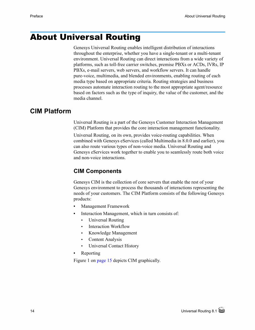
About Universal RoutingGenesys Universal Routing enables intelligent distribution of interactions throughout the enterprise, whether you have a single-tenant or a multi-tenant environment. Universal Routing can direct interactions from a wide variety of platforms, such as toll-free carrier switches, premise PBXs or ACDs, IVRs, IP PBXs, e-mail servers, web servers, and workflow servers. It can handle pure-voice, multimedia, and blended environments, enabling routing of each media type based on appropriate criteria. Routing strategies and business processes automate interaction routing to the most appropriate agent/resource based on factors such as the type of inquiry, the value of the customer, and the media channel.
CIM Platform
Universal Routing is a part of the Genesys Customer Interaction Management (CIM) Platform that provides the core interaction management functionality.
Universal Routing, on its own, provides voice-routing capabilities. When combined with Genesys eServices (called Multimedia in 8.0.0 and earlier), you can also route various types of non-voice media. Universal Routing and Genesys eServices work together to enable you to seamlessly route both voice and non-voice interactions.
CIM Components
Genesys CIM is the collection of core servers that enable the rest of your Genesys environment to process the thousands of interactions representing the needs of your customers. The CIM Platform consists of the following Genesys products:
• Management Framework
• Interaction Management, which in turn consists of: Universal Routing Interaction Workflow Knowledge Management Content Analysis Universal Contact History
• Reporting
Figure 1 on page 15 depicts CIM graphically.
Business Process—User’s Guide 15
Preface About Universal Routing
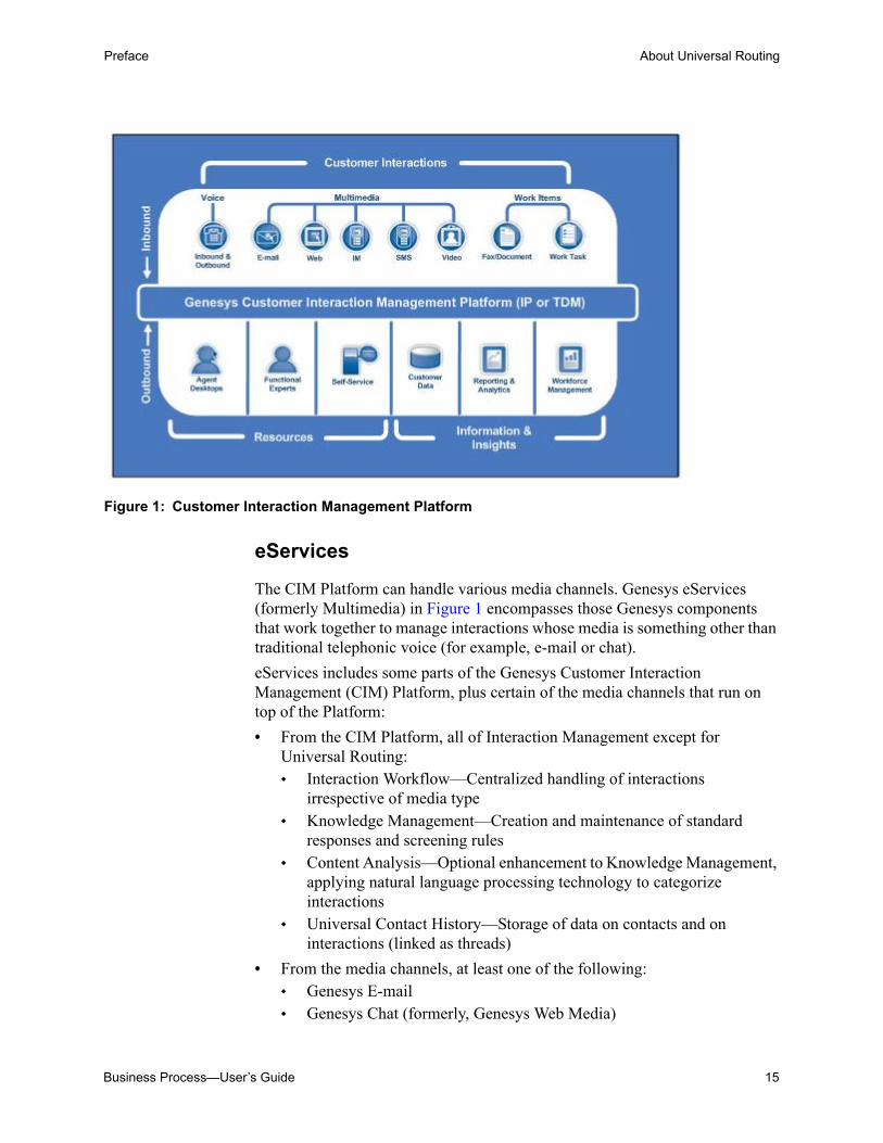
Figure 1: Customer Interaction Management Platform
eServices
The CIM Platform can handle various media channels. Genesys eServices (formerly Multimedia) in Figure 1 encompasses those Genesys components that work together to manage interactions whose media is something other than traditional telephonic voice (for example, e-mail or chat).
eServices includes some parts of the Genesys Customer Interaction Management (CIM) Platform, plus certain of the media channels that run on top of the Platform:
• From the CIM Platform, all of Interaction Management except for Universal Routing: Interaction Workflow—Centralized handling of interactions
irrespective of media type Knowledge Management—Creation and maintenance of standard
responses and screening rules Content Analysis—Optional enhancement to Knowledge Management,
applying natural language processing technology to categorize interactions
Universal Contact History—Storage of data on contacts and on interactions (linked as threads)
• From the media channels, at least one of the following: Genesys E-mail Genesys Chat (formerly, Genesys Web Media)

16 Universal Routing 8.1
Preface Intended Audience
Genesys SMS (Short Message Service) Genesys MMS (Multimedia Messaging Service) Genesys Web Callback Genesys 3rd Party Media—Ability to add customized support for other
media (fax, for example) Optionally, Web Collaboration—Ability for agents and customers to
co-browse (simultaneously navigate) shared web pages. This is an option that you can add to either Genesys Chat or Inbound Voice.
See Figure 2.
Figure 2: eServices in Relation to the CIM Platform and Media Channels
Any functioning solution (platform plus channels) that includes any part of the Interaction Management sector requires Universal Routing
Intended AudienceThis guide is primarily intended for contact center staff responsible for creating business processes. It assumes that you have a basic understanding of:
• Computer-telephony integration concepts, processes, terminology, and applications.
• Network design and operation.
• Familiarity with your own network configurations.
• The Genesys CIM platform.
Ideally, you also have experience designing routing strategies using Interaction Routing Designer (IRD).
Framework
Reporting
Interaction ManagementUniversal Routing
Content Analysis
Interaction Workflow Universal Contact History
Genesys 3rd Party Media
Genesys Chat
Genesys E-mail
Genesys Network Voice
Genesys Inbound Voice
(others)
CIM
Pla
tfor
m
Media Channels
eServices (Multimedia)
Knowledge Management

Business Process—User’s Guide 17
Preface Making Comments on This Document
Making Comments on This DocumentIf you especially like or dislike anything about this document, feel free to e-mail your comments to [email protected].
You can comment on what you regard as specific errors or omissions, and on the accuracy, organization, subject matter, or completeness of this document. Please limit your comments to the scope of this document only and to the way in which the information is presented. Contact your Genesys Account Representative or Genesys Technical Support if you have suggestions about the product itself.
When you send us comments, you grant Genesys a nonexclusive right to use or distribute your comments in any way it believes appropriate, without incurring any obligation to you.
Contacting Genesys Technical SupportIf you have purchased support directly from Genesys, please contact Genesys Technical Support.
Before contacting technical support, please refer to the Genesys Care Program Guide for complete contact information and procedures.
Document Change HistoryThis section lists topics that are new or that have changed significantly since the first release of this document.
Release 8.1.3
• Chapter 1, “Business Process Overview” on page 21: The Hide Activity feature was added. See “Strategy Object” on
page 30 for additional details.
• Chapter 10, “Creating Business Process Objects” on page 247: “Distribution of Load Between Multiple Interactions Servers” on
page 315 section was added.
Release 8.1.1
• Chapter 11, “Planning a Business Process” on page 195: In the section, “IRD Limitations” on page 219, a bullet item has been
added to describe a new limitation and a sentence has been added to the Note on page 215, referring to this new limitation.

18 Universal Routing 8.1
Preface Document Change History
• Appendix, “Business Process Samples” on page 369: A new section, “How To: Conduct a Survey by Using Email” on
page 425 has been added to describe the Email or Chat Survey Business Process.

Business Process—User’s Guide 19
Part
1 Introduction to Business ProcessesPart One of the Universal Routing 8.1 Business Process User’s Guide presents an overview of business processes. It also gives a high level description of Genesys interaction processing. The information in Part One is divided into the following chapters:
• Chapter 1, “Business Process Overview,” on page 21.
• Chapter 2, “Interaction Processing,” on page 47.

20 Universal Routing 8.1
Part 1: Introduction to Business Processes

Business Process—User’s Guide 21
Chapter
1 Business Process Overview This chapter gives a high-level overview of a business process. It covers the following topics: Business Process Definition, page 21 Conceptual Diagrams, page 24 Sample Business Process, page 25 Business Process Objects, page 27 Processing Flow, page 42 Visual Comparison, page 44
Business Process DefinitionA business process directs customer interactions that arrive at the contact center through various processing objects. It defines what happens to customer interactions from the point of arrival to the point of completion. You can create one large business process or a number of smaller business processes connected via queues. A group of business processes comprise an interaction workflow.
Interaction Workflow
An interaction workflow implements the procedures used by agents, supervisors, quality assurance, and other personnel in your company to accomplish business objectives related to incoming interactions. This workflow can be broken down into various segments. IRD enables you to represent such segments as individual business processes.
A business process is a logically-organized series of steps that, working together, handle a task or some aspect of a task and that therefore contributes to your overall workflow processing. Think of business processes as containers for performing general tasks, such as moving interactions in and out of queues

22 Universal Routing 8.1
Chapter 1: Business Process Overview Business Process Definition
and submitting interactions to routing strategies. You can transfer interactions or tasks from one business process to another.
Processing by Media Type
The types of processing applied to interactions varies based on the media type and the contact center’s business logic. In most cases, the goal is to generate an appropriate response for the customer.
• In the case of an e-mail interaction, an appropriate response might be an e-mail answering the customer’s questions.
• In the case of a chat interaction, an appropriate response might be mailing product brochures to the customer.
• In the case of a fax interaction, an appropriate response might be an e-mail stating the requested materials had been received, and so on.
E-mail Server Example
Assume an e-mail interaction from a customer arrives at the contact center, either via the enterprise mail server or, if the customer sends an e-mail from a web site by filling out a web form, the interaction arrives via the Web API Server.
The media server (E-mail Server in this example) stores the body of the interaction in the Universal Contact Server database, and then sends operational data on the interaction to Interaction Server.
Interaction Server parks the interaction’s operational data in its cache and starts processing the data according to the first business process in the interaction workflow.
In general, a business process works as follows:
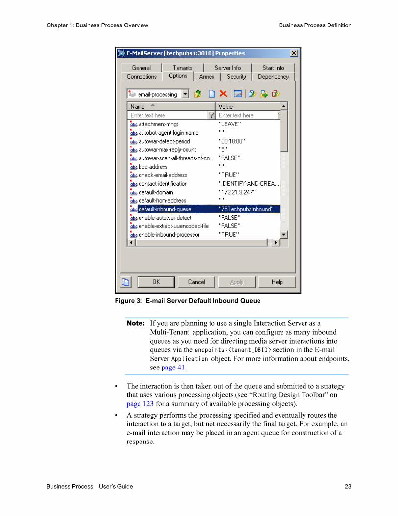
• E-mail Server directs Interaction Server to place the interaction into an inbound queue. Figure 3 shows an example inbound queue defined in an example E-mail Server Application object):
Business Process—User’s Guide 23
Chapter 1: Business Process Overview Business Process Definition
Figure 3: E-mail Server Default Inbound Queue
Note: If you are planning to use a single Interaction Server as a Multi-Tenant application, you can configure as many inbound queues as you need for directing media server interactions into queues via the endpoints:<tenant_DBID> section in the E-mail Server Application object. For more information about endpoints, see page 41.
• The interaction is then taken out of the queue and submitted to a strategy that uses various processing objects (see “Routing Design Toolbar” on page 123 for a summary of available processing objects).
• A strategy performs the processing specified and eventually routes the interaction to a target, but not necessarily the final target. For example, an e-mail interaction may be placed in an agent queue for construction of a response.
24 Universal Routing 8.1
Chapter 1: Business Process Overview Conceptual Diagrams
• The target processes the interaction and places it into another queue where another strategy may process it. For example, a strategy may send an agent’s draft e-mail response to a queue for Quality Assurance checking.
• The cycle of going from queue to strategy to queue continues until processing is stopped or the interaction reaches some final (usually outbound) queue.
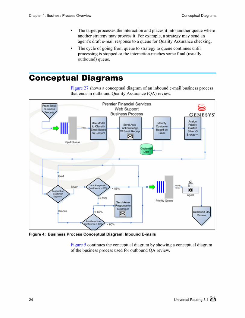
Conceptual DiagramsFigure 27 shows a conceptual diagram of an inbound e-mail business process that ends in outbound Quality Assurance (QA) review.
Figure 4: Business Process Conceptual Diagram: Inbound E-mails
Figure 5 continues the conceptual diagram by showing a conceptual diagram of the business process used for outbound QA review.

Business Process—User’s Guide 25
Chapter 1: Business Process Overview Sample Business Process
Figure 5: Business Process Conceptual Diagram: Outbound QA Review
Sample Business ProcessNote: For information about the interface that is used to create business
processes, see Chapter 3, “Business Process Interface,” on page 57.
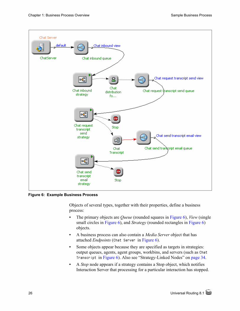
An actual business process in IRD’s Interaction Design window resembles a diagram. Figure 6 shows an example business process that forwards incoming chat interactions to agents and processes chat transcripts.
26 Universal Routing 8.1
Chapter 1: Business Process Overview Sample Business Process
Figure 6: Example Business Process
Objects of several types, together with their properties, define a business process:
• The primary objects are Queue (rounded squares in Figure 6), View (single small circles in Figure 6), and Strategy (rounded rectangles in Figure 6) objects.
• A business process can also contain a Media Server object that has attached Endpoints (Chat Server in Figure 6).
• Some objects appear because they are specified as targets in strategies: output queues, agents, agent groups, workbins, and servers (such as Chat Transcript in Figure 6). Also see “Strategy-Linked Nodes” on page 34.
• A Stop node appears if a strategy contains a Stop object, which notifies Interaction Server that processing for a particular interaction has stopped.

Business Process—User’s Guide 27
Chapter 1: Business Process Overview Business Process Objects
• Lines from queues to routing strategies represent Submitter processes (75tpin in Figure 6).
• Lines flowing out from routing strategies point to targets (smaller nodes, such as the line connecting to Chat distribution in Figure 6).
Business Process ObjectsThis section discusses the various objects that can appear in a business process.
Queue Object
A Queue object represents a logical parking place (persistent queue) for an interaction during its lifetime at the contact center. Figure 7 shows a Queue object, named Inbound emails.
Figure 7: Queue Object
Double-clicking a Queue object opens a properties dialog box (see Figure 8).
Figure 8: Queue Properties Dialog Box
Select the Default check box to make this the default queue for this Business Process. A default queue is marked with a bright-green square in the Object Browser ().
28 Universal Routing 8.1
Chapter 1: Business Process Overview Business Process Objects
Setting a queue as default means that when you configure a new Media Server object for this Business Process, it automatically uses the selected queue.
Note: In this example, the display name (Inbound-e-mails) and the Configuration Manager Script object name (Inbound e-mails1) are slightly different. Figure 143 on page 159 shows an example Configuration Manager Scripts folder for Script objects.
A Queue object has special ports for outgoing connections. Such ports represent View objects. The same queue can be used in more than one business process—for example to connect one business process to another thereby creating an interaction workflow.
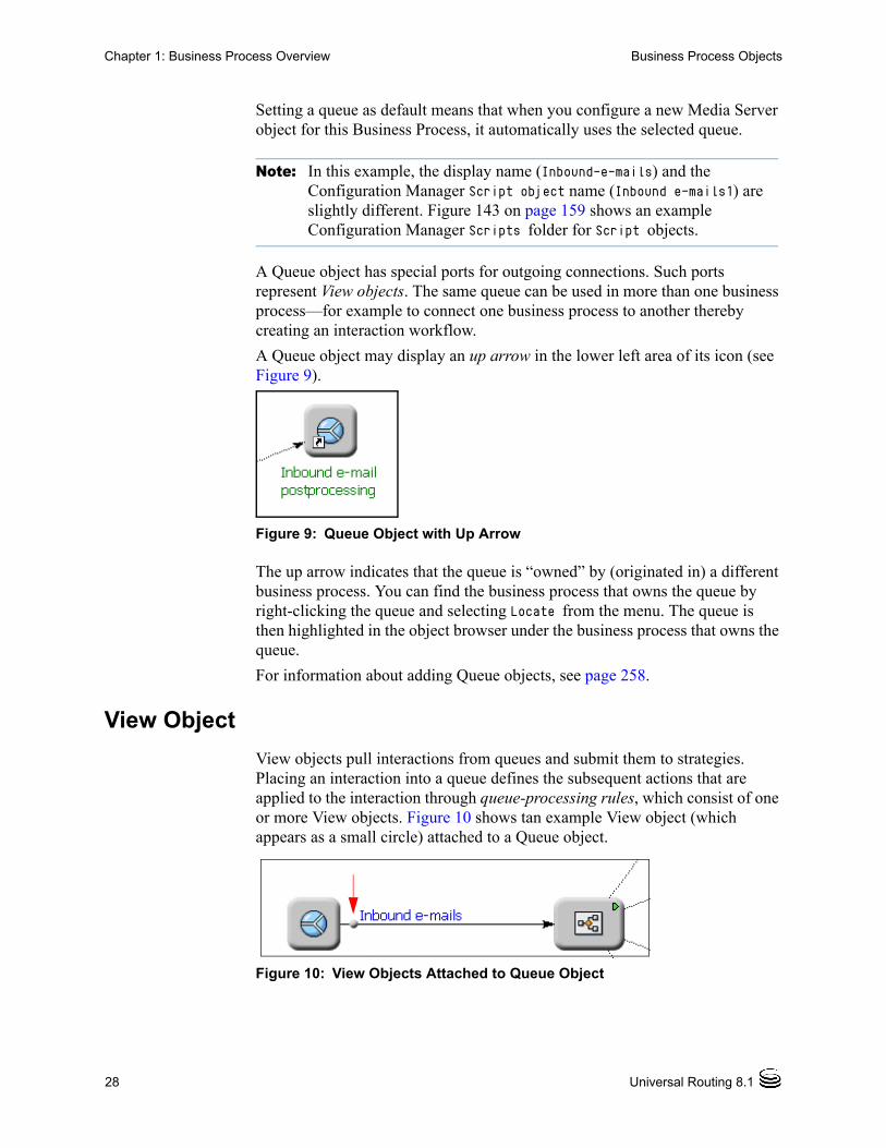
A Queue object may display an up arrow in the lower left area of its icon (see Figure 9).
Figure 9: Queue Object with Up Arrow
The up arrow indicates that the queue is “owned” by (originated in) a different business process. You can find the business process that owns the queue by right-clicking the queue and selecting Locate from the menu. The queue is then highlighted in the object browser under the business process that owns the queue.
For information about adding Queue objects, see page 258.
View Object
View objects pull interactions from queues and submit them to strategies. Placing an interaction into a queue defines the subsequent actions that are applied to the interaction through queue-processing rules, which consist of one or more View objects. Figure 10 shows tan example View object (which appears as a small circle) attached to a Queue object.
Figure 10: View Objects Attached to Queue Object

Business Process—User’s Guide 29
Chapter 1: Business Process Overview Business Process Objects
Right-clicking a View object in the object browser and selecting Properties opens a properties dialog box. You can also open the properties dialog box by right-clicking the associated Queue object and selecting Properties of and the name of the View object.
The example in Figure 11 shows a condition for pulling interactions in the Condition tab.
Figure 11: View Properties Dialog Box
A View object defines one or more of the following:
• The name for the View object in the Configuration Manager Scripts folder (see page 271).
• The conditions for interaction selection including parameterized conditions, such as those used by Agent Desktop (see pages 272 and 282).
• The order of interaction selection (see page 274).
• The time interval that Interaction Server uses to check for interactions (page 275).
• The schedule for submitting interactions to strategies (see page 275).
• Database hints (see page 283).
• The number of interactions of different segments (see page 284).
In addition, you can use Configuration Manager to limit the number of interactions based on interaction properties, such as Customer Segment (see page 287).
For information about adding View objects, see page 267.
30 Universal Routing 8.1
Chapter 1: Business Process Overview Business Process Objects
Strategy Object
Note: All objects used in a strategy are hidden if the Strategy object represents a shortcut. To view the objects used in such strategy, you have to first locate the business process that owns the strategy by right-clicking the strategy, and then selecting Locate. Then open the strategy in that business process.
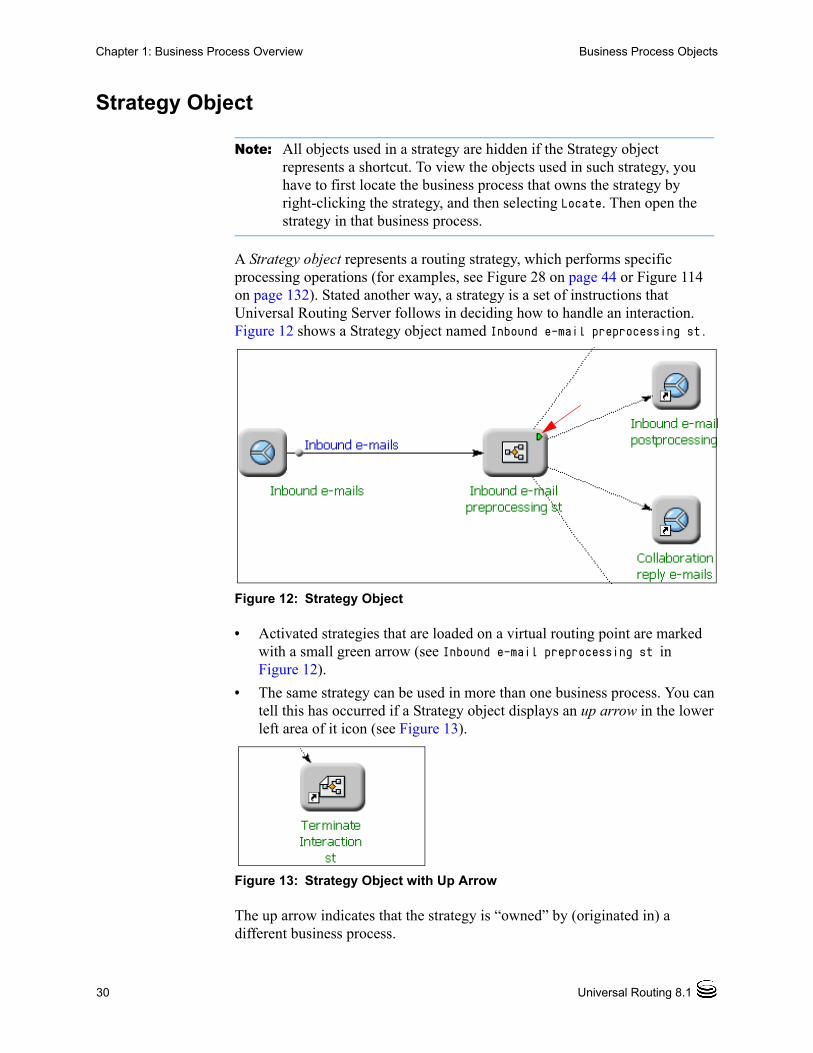
A Strategy object represents a routing strategy, which performs specific processing operations (for examples, see Figure 28 on page 44 or Figure 114 on page 132). Stated another way, a strategy is a set of instructions that Universal Routing Server follows in deciding how to handle an interaction. Figure 12 shows a Strategy object named Inbound e-mail preprocessing st.
Figure 12: Strategy Object
• Activated strategies that are loaded on a virtual routing point are marked with a small green arrow (see Inbound e-mail preprocessing st in Figure 12).
• The same strategy can be used in more than one business process. You can tell this has occurred if a Strategy object displays an up arrow in the lower left area of it icon (see Figure 13).
Figure 13: Strategy Object with Up Arrow
The up arrow indicates that the strategy is “owned” by (originated in) a different business process.

Business Process—User’s Guide 31
Chapter 1: Business Process Overview Business Process Objects
You can find the business process that owns the strategy by right-clicking the strategy and selecting Locate from the menu. The strategy is then highlighted in the object browser under the business process that owns the strategy.
Double-clicking a Strategy object opens a properties dialog box with the name of the Configuration Manager Script object (see Figure 14), its description, and the path where the graphical portion (.rbn file) is stored (see page 172).
Figure 14: Strategy Properties Dialog Box
• To examine the strategy detail and flow, you can open the strategy for viewing (see Figure 260 on page 305).
• For information about creating Strategy objects, see page 323.
• If the Hide activity check box is selected, no activity related to the strategy is reported by Interaction server.
When the Hide Activity checkbox is checked, it stores a value of true for the hide-activity option in the default section on the Annex tab of a strategy configuration object. Or as a value of false if the Hide Activity checkbox is unchecked. See Figure 15 for details.

32 Universal Routing 8.1
Chapter 1: Business Process Overview Business Process Objects
Figure 15: hide-activity Option
Certain activities defined in Business Processes and handled by Interaction Server are intended to periodically check interactions and modify their properties.
For instance, an interaction can be pulled from a queue, pushed to a specific strategy, which changes the interaction’s properties, and returned back into the same queue. This activity is reported by the following sequence of events, and can happen multiple times until finally the interaction is either moved to another queue or routed to an agent:
• EventTakenFromQueue (interaction leaving a queue)
• EventPartyAdded (strategy added as a party)
• EventPropertyChanged (one or more changes, if any)
• EventPartyRemoved (strategy party removed)
• EventPlacedInQueue (interaction returned back to the same queue)
If a customer is not interested in reporting these interim changes, all corresponding reporting events can be eliminated in order to not waste network bandwidth and reporting engine CPU.

Business Process—User’s Guide 33
Chapter 1: Business Process Overview Business Process Objects
The Interaction Server reads the value of the strategy hide-activity option when it reads the configuration of a corresponding Business Process, and does not report the activity associated with this strategy if the option’s value is set to true.
Workbin Object
A workbin is an object that holds interactions for later processing. Figure 16 shows the properties dialog box for a workbin.
Figure 16: Workbin Properties Dialog Box
• In Genesys Agent Desktop, agents can use workbins to store interactions that they have started working on and wish to continue working on at a later time. For more information, see the Genesys Desktop 7.6 Deployment Guide.
• Interactions can be distributed to workbins by Universal Routing Server when executing a strategy that uses the Workbin object (see “Workbin Strategy-Linked Node” on page 37).
• Workbins may be used in a business process for escalation functionality (see page 298). Multiple workbins may be associated with the same interaction queue.
A workbin is similar to a queue in that it holds interactions. A workbin differs from a queue in that, when configured with IRD’s Workbin routing object, a workbin can be associated with a particular Agent/Agent Group/Place/Place Group. In this case, its major function is to hold interactions for that agent/place/group to process. Agents can view the entire content of a workbin and pull interactions from it in any order. Agents can also pull interactions from queues, but only in the order defined by the queue.
Note: For more information on configuring workbins, refer to “Adding Workbins” on page 292.

34 Universal Routing 8.1
Chapter 1: Business Process Overview Business Process Objects
Strategy Activity
Strategy-Linked Nodes
Outgoing connections automatically appearing from a Strategy object that represent objects specified inside the strategy are called strategy-linked nodes. For example, assume a strategy in a business processes contains the following:
• A Queue Interaction object (see Table 11 on page 207)
• A Workbin object (see Table 11 on page 207)
• A Route Interaction object using a variable for the name of the routing target (see Table 11 on page 207)
• A predefined queue called Stop_Processing
Figure 17 shows the resulting strategy-linked nodes.
Figure 17: Strategy-Linked Nodes
The next section discusses the various types of strategy-linked nodes.
Queue Strategy-Linked Node
If the Strategy object uses a Multimedia object (see Table 8 on page 201) or a Routing object (see Table 11 on page 207) that names an interaction queue, a
Business Process—User’s Guide 35
Chapter 1: Business Process Overview Business Process Objects
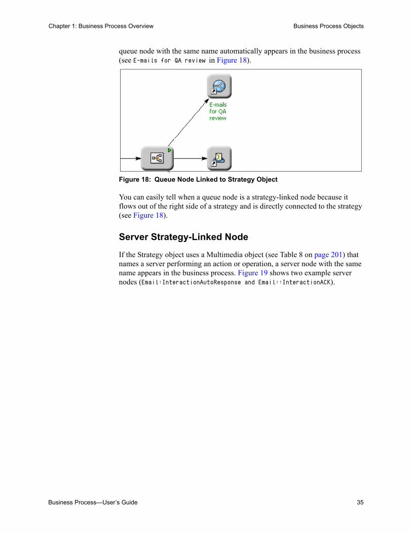
queue node with the same name automatically appears in the business process (see E-mails for QA review in Figure 18).
Figure 18: Queue Node Linked to Strategy Object
You can easily tell when a queue node is a strategy-linked node because it flows out of the right side of a strategy and is directly connected to the strategy (see Figure 18).
Server Strategy-Linked Node
If the Strategy object uses a Multimedia object (see Table 8 on page 201) that names a server performing an action or operation, a server node with the same name appears in the business process. Figure 19 shows two example server nodes (Email:InteractionAutoResponse and Email::InteractionACK).

36 Universal Routing 8.1
Chapter 1: Business Process Overview Business Process Objects
Figure 19: Server Node Linked to Strategy Object
Stop Strategy-Linked Node
If the Strategy object uses a Stop Interaction object (see Table 8 on page 201), a Stop node appears in the business process (see Figure 19). This node specifies the end point for processing of an interaction in a strategy.
Target Strategy-Linked Node
If the Strategy object uses a Route Interaction object (see Table 8 on page 201) that specifies a Person, Agent Group, or Skill (see page 241) as a routing target, a node with the same name appears in the business process. Figure 20 shows an example Agent Group target node (Email QA Review group).

Business Process—User’s Guide 37
Chapter 1: Business Process Overview Business Process Objects
Figure 20: Person Node Linked to Strategy Object
Workbin Strategy-Linked Node
If the Strategy object routes an interaction using the Workbin object (see Table 8 on page 201), a workbin node appears in the business process (see Figure 21).
Figure 21: Workbin Strategy-Linked Node
In the case of a workbin strategy-linked node, the Workbin object in the strategy specifies a target type: Agent, Agent Group, Place, or Place Group. The selected target type appears under Owner in the Workbin Properties dialog box (see Figure 16 on page 33).
The same workbin can be used in more than one business process. A workbin strategy-linked node may display an up arrow in the lower left area of it icon (see Figure 22).

38 Universal Routing 8.1
Chapter 1: Business Process Overview Business Process Objects
Figure 22: Workbin Object Owned by a Different Business Process
The up arrow indicates that the workbin is “owned” by a different business process.
You can find the business process that owns (originated) the workbin by right-clicking the workbin and selecting Locate from the menu. The workbin is highlighted in the object browser (see Figure 36 on page 61) under the business process that owns the workbin.
• Views extract interactions from workbins.
• For information about creating Workbin objects, see page 292.
Note: The Workflow Settings tab in the Options dialog box (see Figure 75 on page 90) affects the visibility of strategy-linked nodes.
New and Existing Interactions
To distinguish existing interactions from new ones, the lines connecting an object that creates a new interaction and the destination for the new interaction are red instead of black.
• If a strategy places an existing interaction in a queue, IRD inserts a Queue strategy-linked node and uses a black connection between the strategy and the queue.
• If a strategy stops interaction processing, IRD inserts a Stop strategy-linked node and uses a black connection to the strategy.
• If a strategy calls a 3rd-party server that creates a new interaction and places it into a queue, IRD inserts the server strategy-linked node and connects it to both the strategy (black connection) and the queue (red connection). See Figure 19 on page 36.
• If a strategy routes the interaction to an agent, IRD inserts an agent strategy-linked node and connects it to the strategy using a black connection.
• If the agent is supposed to stop interaction processing, IRD inserts a Stop strategy-linked node and connects it with the agent node using a black connection.
• If the agent is supposed to place an interaction in a queue, IRD connects the agent strategy-linked node to the queue using a black connection.

Business Process—User’s Guide 39
Chapter 1: Business Process Overview Business Process Objects
• If the agent is supposed to create new interaction and place it in a queue, IRD connects the agent strategy-linked node to the queue using a red connection.
Submitters
When you connect a View object (see Figure 10 on page 28) to a Strategy object, this action defines a Submitter, which fetches interactions through a corresponding view and submits them to the strategy.
Figure 23 shows a Submitter connecting the Inbound e-mails Queue object with the Inbound e-mail processing st Strategy object.
Figure 23: Submitter Object
For information about creating Submitter objects, see page 303.
Media Server Object
At some point, you will need to direct customer interactions into the workflow. The only way to get customer interactions into a workflow (for further processing by other business processes) is to use a Media Server object. The location where the Media Server object is used will frequently be the first business process in the workflow, but the exact location depends on how you design your workflow.
Background
The Genesys Multimedia software components include five media servers, E-mail Server, Chat Server, SMS Server, iWD Capture Points, and Third Party Servers, which process e-mail, chat, SMS/MMS interactions, and iWD tasks respectively. Your enterprise’s media servers appear as Media Server objects in a Media Servers folder in the Interaction Design window (see Figure 49 on page 70 for an example).

40 Universal Routing 8.1
Chapter 1: Business Process Overview Business Process Objects
• E-mail Server interfaces with the enterprise mail server and the Genesys Web API Server, bringing in new e-mail interactions from customers and sending out replies or other outbound messages.
• Chat Server works with Web API Server to open, conduct, and close chat interactions between agents and customers.
• SMS Server receives and handles SMS and MMS messages sent from a mobile client.
• iWD Capture Points capture iWD tasks from various source systems.
• Third Party Servers are used to represent servers for which there is no corresponding Application type in Configuration Server.
For more information on the media servers, start with the eServices (Multimedia) 8.0 Deployment Guide.
Figure 24 shows example chat and e-mail Media Server objects used in a business process.
Figure 24: Media Servers and Endpoints
In this particular example, both media servers direct interactions into the same queue (75TechpubsInbound) for sorting. You may want to set up different queues for different media types.
To view a Media Server’s properties, right-click it in the object browser Media Servers folder and select Properties. Figure 25 shows an example dialog box.

Business Process—User’s Guide 41
Chapter 1: Business Process Overview Business Process Objects
Figure 25: Media Server Properties Dialog Box
For information about using Media Server objects, see page 252.
Endpoint Object
In Figure 24, note the small circles attached to each media server. Each small circle is an Endpoint object. An endpoint can be used to connect a media server with a queue in a business process.
To view an endpoint’s properties, right-click it in the Media Servers folder of the object browser and select Properties. Figure 26 shows an example dialog box.
Figure 26: Endpoint Properties Dialog Box
If the endpoint is connected to another object, the Refers To field names the business process and object.
To find the object in the business process to which the endpoint connects, click the Follow the Reference button. IRD highlights the object in the business process.

42 Universal Routing 8.1
Chapter 1: Business Process Overview Processing Flow
For information about creating endpoints in the Interaction Design window, see “Adding Endpoints” on page 254.
Processing FlowFigure 27 shows a flow diagram using objects discussed in “Business Process Objects” on page 27.
Figure 27: Business Process Conceptual Diagram
The processing flow for the diagram is the following:
1. The Inbound E-mails queue accepts all inbound e-mails.
2. The By Date view is attached to the Inbound E-mails queue. The view specifies interaction selection by date received (assumed from the view name).
3. A submitter process pulls interactions from the Inbound E-mails queue (through the By Date view) and submits them to the Analyze & Autoreply strategy.
4. The Analyze & Autoreply strategy analyzes the e-mail based on its content and defines each e-mail’s special attributes such as To whom. The strategy also generates an autoreply e-mail and places it in the Outbound E-mails queue.
Cust. Support
Inboundemails By date
Analyze & Autoreply
STOP
Outboundemails
By date
Email Server
To Email Server
AnalyzedCustomersupport
Sales
Customer SupportAgents
Sales
STOP
Sales Agents
ForApproval
By date
Managers
Managers
1.
2.3.
4.
5.6.
7.
8.
9.
10.
11.
12.
13.
14.15.
16.
17. 18.
19.20.
21.
22. 23.
Business Process—User’s Guide 43
Chapter 1: Business Process Overview Processing Flow
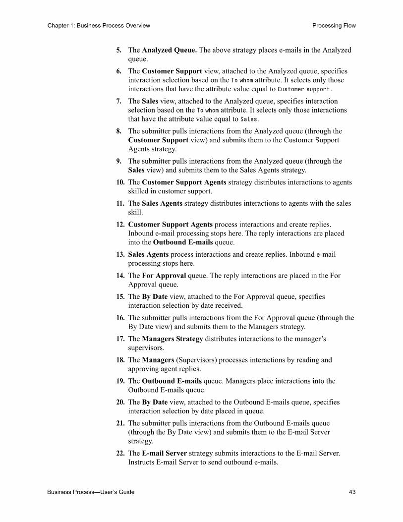
5. The Analyzed Queue. The above strategy places e-mails in the Analyzed queue.
6. The Customer Support view, attached to the Analyzed queue, specifies interaction selection based on the To whom attribute. It selects only those interactions that have the attribute value equal to Customer support.
7. The Sales view, attached to the Analyzed queue, specifies interaction selection based on the To whom attribute. It selects only those interactions that have the attribute value equal to Sales.
8. The submitter pulls interactions from the Analyzed queue (through the Customer Support view) and submits them to the Customer Support Agents strategy.
9. The submitter pulls interactions from the Analyzed queue (through the Sales view) and submits them to the Sales Agents strategy.
10. The Customer Support Agents strategy distributes interactions to agents skilled in customer support.
11. The Sales Agents strategy distributes interactions to agents with the sales skill.
12. Customer Support Agents process interactions and create replies. Inbound e-mail processing stops here. The reply interactions are placed into the Outbound E-mails queue.
13. Sales Agents process interactions and create replies. Inbound e-mail processing stops here.
14. The For Approval queue. The reply interactions are placed in the For Approval queue.
15. The By Date view, attached to the For Approval queue, specifies interaction selection by date received.
16. The submitter pulls interactions from the For Approval queue (through the By Date view) and submits them to the Managers strategy.
17. The Managers Strategy distributes interactions to the manager’s supervisors.
18. The Managers (Supervisors) processes interactions by reading and approving agent replies.
19. The Outbound E-mails queue. Managers place interactions into the Outbound E-mails queue.
20. The By Date view, attached to the Outbound E-mails queue, specifies interaction selection by date placed in queue.
21. The submitter pulls interactions from the Outbound E-mails queue (through the By Date view) and submits them to the E-mail Server strategy.
22. The E-mail Server strategy submits interactions to the E-mail Server. Instructs E-mail Server to send outbound e-mails.

44 Universal Routing 8.1
Chapter 1: Business Process Overview Visual Comparison
23. The E-mail Server. Receives interactions from the E-mail Server strategy and sends outbound e-mails.
Visual ComparisonSo that you can visually compare a strategy and a business process, this section shows both.
Figure 28 shows the Inbound e-mail preprocessing st strategy in the Routing Design window.
Figure 28: Example Strategy
Business Process—User’s Guide 45
Chapter 1: Business Process Overview Visual Comparison
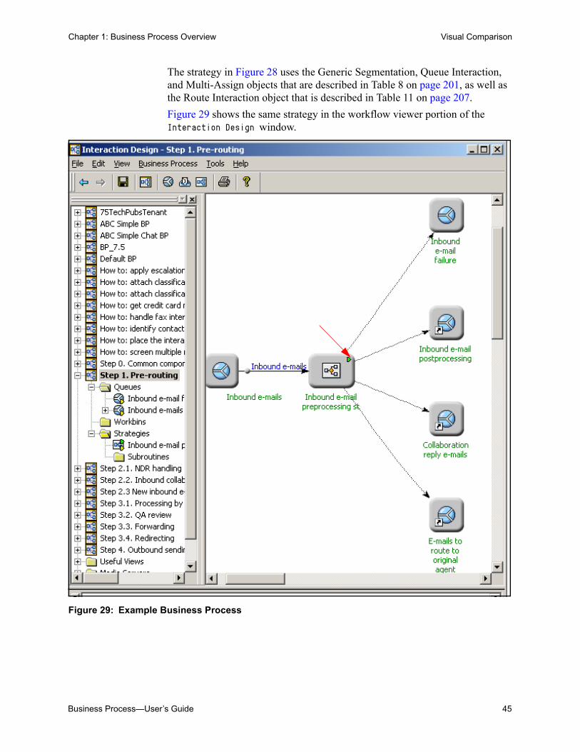
The strategy in Figure 28 uses the Generic Segmentation, Queue Interaction, and Multi-Assign objects that are described in Table 8 on page 201, as well as the Route Interaction object that is described in Table 11 on page 207.
Figure 29 shows the same strategy in the workflow viewer portion of the Interaction Design window.
Figure 29: Example Business Process

46 Universal Routing 8.1
Chapter 1: Business Process Overview Visual Comparison
Business Process—User’s Guide 47
Chapter
2 Interaction ProcessingThis chapter familiarizes you with Genesys interaction processing as it relates to business processes. It covers the following topics: Genesys Queues, page 47 Interaction Workflow Control, page 48 Interaction Flow, page 51 Genesys E-mail, page 51 URS/Interaction Server Communication, page 53
Genesys QueuesThe Genesys software maintains both interaction queues and virtual queues:
• A queue in a business process executed by Interaction Server is called an interaction queue in this document. You might also call this type of queue a persistent queue. Business process developers define interaction queues (Queue objects) and objects that extract interactions from queues (View objects) in the Interaction Design window (see Figure 36 on page 61). The definition of an interaction queue is stored as a Script object in the Configuration Database (see Figure 143 on page 159).
• All interactions submitted to URS are placed in virtual queues. A virtual queue is not a physical queue, but instead a logical queue to which all interactions are queued if the specified target in the routing strategy is not available.
Just as a business process keeps all of its interactions in interaction queues, Universal Routing Server (URS) keeps all of its interactions in virtual queues (the Connections list in the URS Application object can have many different T-Servers). URS communicates with Interaction Server about non-voice interactions, and with voice T-Server about voice interactions.

48 Universal Routing 8.1
Chapter 2: Interaction Processing Interaction Workflow Control
Note: If a target is unavailable, interactions sent to URS by Interaction Server are returned to Interaction Server.
• In addition to interaction and virtual queues, there are also ACDQueue routing target objects. However, the term queue, as used in this guide, refers to an interaction queue.
Note: Genesys supplies business processes and strategies that use interaction queues, as detailed in “Using the Samples” on page 197.
Interaction Workflow ControlAn interaction workflow refers to a group of business processes that are connected via queues (see page 21 if you need a review). An interaction workflow can also be designed as a single large business process similar to the Genesys-supplied Default BP sample business process that is described on page 387.
The Genesys components shown in Figure 30 handle workflow control for non-voice interactions.
Figure 30: Workflow Control Components
Note: Not shown in Figure 30 are other required Genesys Management Framework components, such as Configuration Server and the Management Layer.
To media interface
cache
Training Server
Classification Server
Stat Server
URS, IRD (with
IxDesign)
To data storage
Interaction Server
To agent
MM component
Other Genesys component
Knowledge Manager
Knowledge ManagementOptional MM component
Routing
Interaction Server /cache

Business Process—User’s Guide 49
Chapter 2: Interaction Processing Interaction Workflow Control
The workflow control software components are as follows:
Interaction Server
Interaction Server is the central interchange for multimedia (non-voice) interaction flow.
• It receives interaction operational data from the media interface.
• It stores the operational data in a cache (a database) while receiving and transmitting information about the interaction. This cache also contains queues through which the interaction passes as part of its processing.
• It works in concert with the routing components to route interactions according to business processes and routing strategies.
For more information on Interaction Server, see the eServices (Multimedia) 8.0 Deployment Guide.
Interaction Routing Designer
Through its Interaction Design window, IRD creates and traces business processes, which plot an overall path for interactions (see Figure 6 on page 26). Business processes, executed by Interaction Server, map a route for the interaction between contact center objects—principally, queues and routing strategies. When executing business processes, Interaction Server communicates with Universal Routing Server (URS), which is the server that executes the routing strategies that are contained in business processes.
Note: Genesys recommends using only one IRD application per desktop.
For more information on IRD, see Universal Routing 8.1 Reference Manual.
For information about creating routing strategies, see page 323.
Universal Routing Server
Universal Routing Server (URS) executes routing strategies, which trigger specialized processing tasks, such as sending automatic responses to customers and screening of incoming interactions for certain words. URS also applies segmentation logic to the flow; and requests delivery of the interaction to an agent or other target. For more information on all the specialized processing tasks handled by strategies, see “IRD Objects Used in Business Processes” on page 201.
For more information on URS, see Universal Routing 8.1 Reference Manual. Also see Universal Routing 8.1 Deployment Guide.

50 Universal Routing 8.1
Chapter 2: Interaction Processing Interaction Workflow Control
Stat Server
Stat Server accumulates data about routing targets: Agents, Agent Groups, Places (desks), and other contact center objects; converts the data into statistically useful information; and passes these calculations to other software applications. In particular, it provides agent capacity information to IRD and URS, which refers to the number and types of interactions an agent can accept (see “Agent Capacity Rules” on page 164).
For more information on Stat Server, see Framework 8.1 Stat Server User’s Guide. Also see Genesys 8.0 Resource Capacity Planning Guide.
Knowledge Manager
Knowledge Manager (see Figure 160 on page 177) is the user interface component of Genesys Knowledge Management, which also includes:
• Classification Server, which applies Screening Rules when triggered to do so by a routing strategy. Screening Rules are basic pattern-matching queries performed on e-mail contents. The results of these queries can then be used in routing strategy logic.
• Training Server, which trains the system to recognize Categories. It is active only in the Content Analyzer option (see below).
You use Knowledge Manager to:
• Manage the library of Standard Responses, which is a collection of ready-made responses to common inquiries and topics.
• Manage Screening Rules.
• Manage Categories, which are used to organize Standard Responses.
For more information on Knowledge Manager, see the eServices (Multimedia) 8.0 User’s Guide.
Content Analyzer
Genesys Content Analyzer is an optional enhancement to Knowledge Management, requiring a separate license. It uses natural language processing technology to analyze incoming interactions for assignment to the Categories of the Standard Response Category system. The algorithms for content analysis are built up and refined by Training Server as it processes collections of pre-classified interactions. Setting up and scheduling these training sessions is another function of Knowledge Manager. The content analysis algorithms like Screening Rules, are applied by Classification Server when triggered by routing strategies, and are stored in the Universal Contact Server database.
For more information on Content Analyzer, see the eServices (Multimedia) 8.0 User’s Guide.

Business Process—User’s Guide 51
Chapter 2: Interaction Processing Interaction Flow
Interaction FlowTo summarize interaction flow:
• At the highest level, the flow is controlled by business processes as executed by Interaction Server.
• Each business process contains queues and routing strategies.
• Routing strategies may bring in other applications/components to apply specialized processing tasks to the interaction—for example: Send an acknowledgement or an automatic reply Apply a Screening Rule Apply content analysis (with Content Analyzer option only) Forward or Redirect
For a complete list of specialized processing tasks, see “IRD Objects Used in Business Processes” on page 201.
Genesys E-mailThis section presents architecture that is specific to Genesys E-mail. Figure 31 shows the main components.
Figure 31: E-mail for Multimedia Components
Figure 31 simplifies the workflow control components by showing Knowledge Management and Routing as single objects. E-mail interaction processing generally proceeds as follows:

52 Universal Routing 8.1
Chapter 2: Interaction Processing Genesys E-mail
1. In addition to replies from external resources (see “External Service” on page 210), e-mail interactions arrive at E-mail Server in the following ways:
a. If the customer sends ordinary e-mail, the interaction arrives via the enterprise mail server.
b. If the customer fills out a web form, the interaction arrives via the Web API Server.
2. E-mail Server sends operational data on the interaction to Interaction Server and simultaneously stores the body of the interaction in the Universal Contact Server (UCS) database.
3. Interaction Server parks the interaction’s operational data in its cache and starts processing it according to a business process.
4. What happens next depends on the business process and the routing strategies that it contains. The system may Apply a Screening Rule. Assign one or more Categories to the interaction (if Content Analyzer
is present). Generate an automatic response. Route the interaction to an agent’s desktop, possibly also sending an
automatic acknowledgement to the customer.
A supervisor may intervene at various points as long as the interaction’s operational data remains in the Interaction Server’s cache.
5. The agent receives the interaction. With the Content Analyzer option, the interaction may arrive with a Category assignment and associated suggested response. Otherwise, the agent may search manually for a Category with a suggested response.
6. The agent may then: Simply reply to the interaction. Transfer it to another agent. Produce a collaborative response by consulting with other agents.
7. When the reply is finally released by the agent or agents (typically to an Outbound queue in the Interaction Server cache), it may optionally be routed to a senior agent or supervisor for QA review. The reviewer decides whether to let the reply continue through the outbound part of the business process, return it to the agent for revision, or take other action.

Business Process—User’s Guide 53
Chapter 2: Interaction Processing URS/Interaction Server Communication
URS/Interaction Server CommunicationURS and Interaction Server communicate by using T-Server message protocol where all messages from URS to Interaction Server starts with Request and all messages from Interaction Server to URS start with Event. The basic message set is shown in Table 1.
Interaction Server executes business processes and, in doing so, communicates with URS using a subset of T-Server protocol:
RequestUpdateUserData, RequestAttachUserData, RequestDeletePair,
RequestDistributeEvent for EventQueued, EventDiverted, EventPartyAdded, EventPartyRemoved, and EventAbandoned are supported.
The message types that are shown in Table 2 for third party servers (such as Universal Contact Server and E-mail Server) are also supported.
You can use these messages in the log file when you are diagnosing strategy/routing problems. For more information, see the eServices (Multimedia) 8.0 Open Media Interaction Models Reference Manual. It has examples of basic scenarios that involve messaging between Interaction Server and other components, including URS.
Table 1: Basic URS/Interaction Server Communication Protocol
Name Direction Comment
EventRouteRequest from Interaction Server to URS
Ask URS to find appropriate target (Place, Agent, …) for given interaction
RequestRouteCall from URS to Interaction Server
Provide Interaction Server with target information for a given interaction
EventRouteUsed from Interaction Server to URS
Report to URS about successful processing or command to cancel strategy execution for this interaction (ReferenceID = 0)
Table 2: URS/Interaction Server Request and Event Messages
Name or Request/Event Direction Comment
Request3rdServer From URS to Interaction Server
Send to Interaction Server request for third-party server operation
Event3rdServerResponse From Interaction Server to URS
Returns results of third-party server operation
Event3rdServerFault From Interaction Server to URS
Supply error information about third-party server operation failure

54 Universal Routing 8.1
Chapter 2: Interaction Processing URS/Interaction Server Communication

Business Process—User’s Guide 55
Part
2 User InterfacesPart Two of the Universal Routing 8.1 Business Process User’s Guide familiarizes you with the various Genesys user interfaces involved with creating business processes.
The information in Part Two is divided into the following chapters:
• Chapter 3, “Business Process Interface” beginning on page 57, describes the features and functions of the interface used for business process design and configuration.
• Chapter 4, “Strategy Interface” beginning on page 103, describes the features and functions of the interface used for routing strategy design and configuration.
• Chapter 5, “Configuration Layer Interface” beginning on page 155, describes the features and functions of the interface used to define Genesys Configuration Layer objects.
• Chapter 6, “Knowledge Manager Interface” beginning on page 175, describes the interface used to define Standard Responses, classification Categories, and other elements required by certain IRD objects.

56 Universal Routing 8.1
Part 2: User Interfaces

Business Process—User’s Guide 57
Chapter
3 Business Process InterfaceThis chapter introduces the interface that is used to create business processes. Find step-by-step instructions for creating a business process on page 247.
This chapter covers the following topics: Opening IRD, page 57 Accessing Interaction Design, page 60 Object Browser, page 62 Workflow Viewer, page 70 Viewers, page 71 File Menu, page 73 Edit Menu, page 78 View Menu, page 80 Business Process Menu, page 82 Tools Menu, page 83 Help Menu, page 93 Shortcut Menus, page 93 Interaction Design Shortcut Bar, page 100
Note: Prior to 7.1, business processes were created outside of IRD in a standalone application that was called Interaction Workflow Designer.
Opening IRDThe information in this section assumes that you have already installed IRD as described in the Universal Routing 8.1 Deployment Guide.

58 Universal Routing 8.1
Chapter 3: Business Process Interface Opening IRD
Procedure:Logging into Interaction Routing Designer
Purpose: To access the interfaces that are used for creating strategies as well as the interfaces that are used for creating business processes.
Start of procedure
1. Click the desktop shortcut if a shortcut is present (see Figure 32).
Figure 32: Interaction Routing Designer Desktop Icon
As an alternative, click the Start button on your computer desktop and select Programs > Genesys Solutions > Routing > Interaction Routing Designer > Start Interaction Routing Designer.
2. Respond to any security-related screens that your company may have configured to appear before the Interaction Routing Designer login dialog box.
3. Complete the Interaction Routing Designer login dialog box. Figure 33 shows dialog box with example entries after clicking Details<<.
Figure 33: Interaction Routing Designer Login Dialog Box
The first time the login dialog box opens, all fields are empty. The next time you log in, IRD “remembers” previous entries for the following fields: User name, Application, Host name, and Port.

Business Process—User’s Guide 59
Chapter 3: Business Process Interface Opening IRD
4. Use the information in Table 3 to complete the login dialog box shown in Figure 33.
5. Click OK, the Strategies list pane opens. Figure 34 shows an example.
Figure 34: Strategies List Pane
End of procedure
Table 3: IRD Login Dialog Box
Field Description
User name: Name of Person object that is defined in Configuration Manager (see Figure 144 on page 160). See “Setting Permissions” on page 173.
User password: Password of Person object in Configuration Manager.
Application: Enter the name of an IRD Application that is defined in Configuration Manager (see Figure 141 on page 157).
Host name: Name of machine where Configuration Server is running.
Port: Port number used by Configuration Server.
shortcutbars
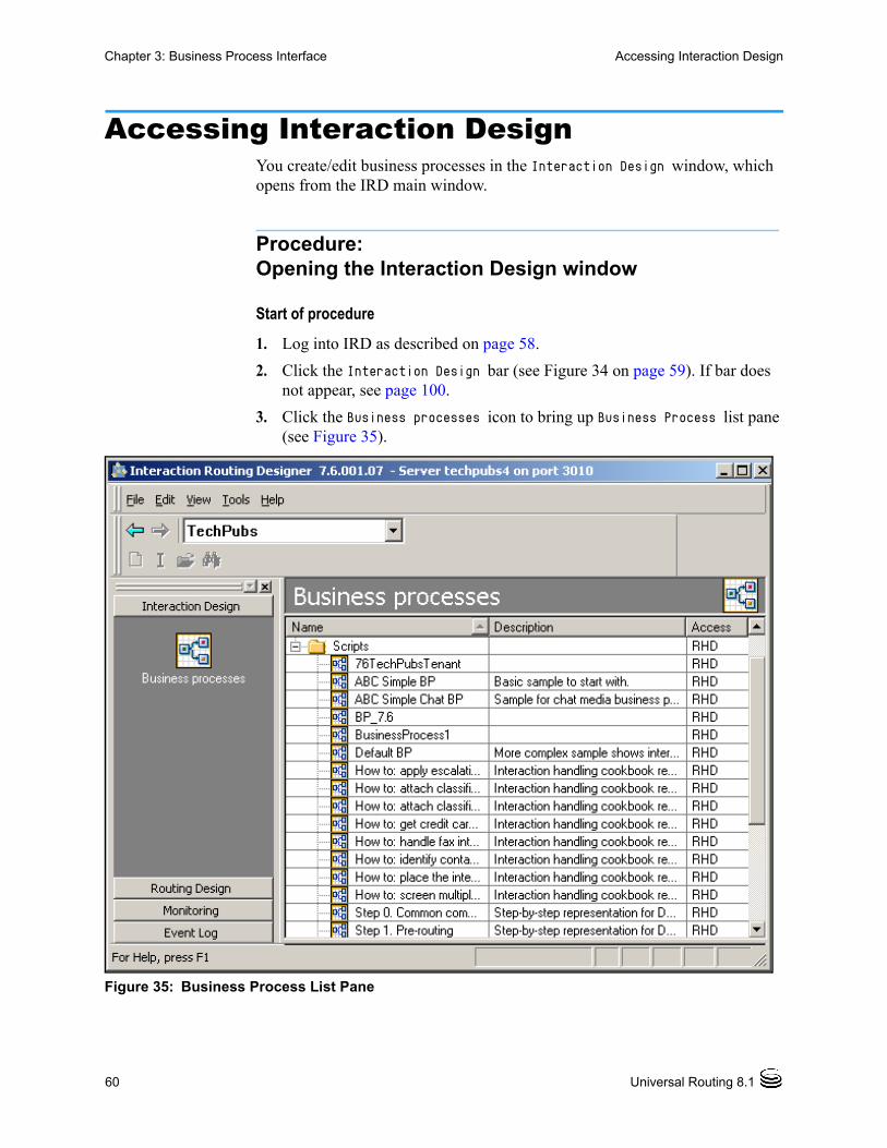
60 Universal Routing 8.1
Chapter 3: Business Process Interface Accessing Interaction Design
Accessing Interaction DesignYou create/edit business processes in the Interaction Design window, which opens from the IRD main window.
Procedure:Opening the Interaction Design window
Start of procedure
1. Log into IRD as described on page 58.
2. Click the Interaction Design bar (see Figure 34 on page 59). If bar does not appear, see page 100.
3. Click the Business processes icon to bring up Business Process list pane (see Figure 35).
Figure 35: Business Process List Pane
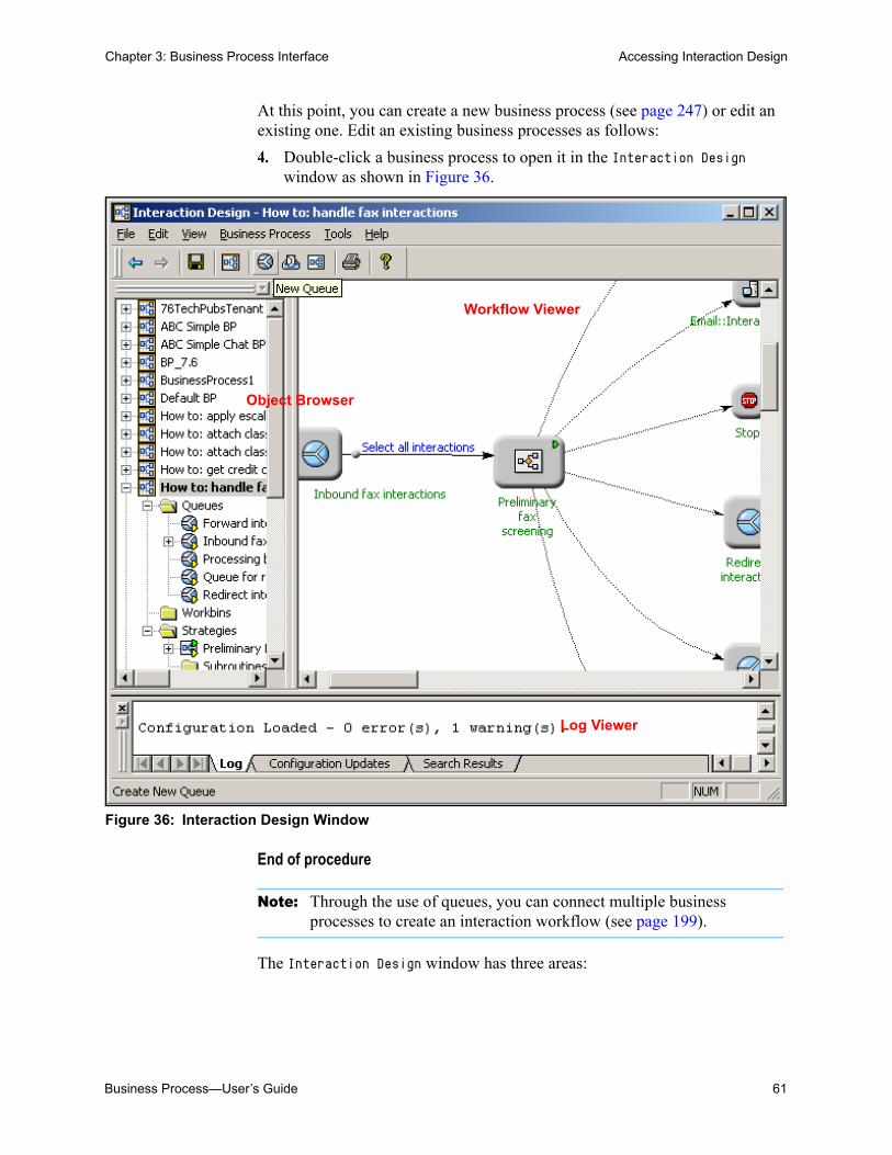
Business Process—User’s Guide 61
Chapter 3: Business Process Interface Accessing Interaction Design
At this point, you can create a new business process (see page 247) or edit an existing one. Edit an existing business processes as follows:
4. Double-click a business process to open it in the Interaction Design window as shown in Figure 36.
Figure 36: Interaction Design Window
End of procedure
Note: Through the use of queues, you can connect multiple business processes to create an interaction workflow (see page 199).
The Interaction Design window has three areas:
Object Browser
Log Viewer
Workflow Viewer

62 Universal Routing 8.1
Chapter 3: Business Process Interface Object Browser
• An object browser (dockable) on the left displays queues, views, routing strategies, strategy-linked nodes, media servers, and endpoints in a tree style.
• A workflow viewer (static) on the right displays the selected business process.
• A log viewer (dockable) at the bottom of the window displays a running list of status and event messages.
The next section discusses each area.
Object BrowserBy default, each business process has the following folders: Queues, Workbins, Strategies, and Subroutines.
When a business process is expanded, the object browser (see Figure 36 on page 61) displays its configuration objects in a tree structure. Assume that you expand the folders in an example business process that uses queues, workbins, and strategies, but not subroutines. The object browser appears as shown in Figure 37.
Figure 37: Object Browser
Small Yellow Triangle
Once you use an object in a business process, the browser marks it with a small yellow triangle. For example, in Figure 37 under Queues, see E-mails failed QA. The yellow triangle is helpful when working with a large business process when you cannot see all objects at once and you are unsure whether a particular object has been dropped in the viewer.
• If you see the yellow triangle, the object has been dropped in the viewer.
Queue Object
View Object
Strategy Object
Business Process
Agent Strategy-Linked NodeStop Strategy-Linked Node
Workbin Object
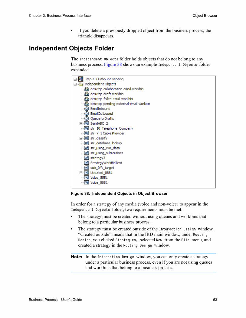
Business Process—User’s Guide 63
Chapter 3: Business Process Interface Object Browser
• If you delete a previously dropped object from the business process, the triangle disappears.
Independent Objects Folder
The Independent Objects folder holds objects that do not belong to any business process. Figure 38 shows an example Independent Objects folder expanded.
Figure 38: Independent Objects in Object Browser
In order for a strategy of any media (voice and non-voice) to appear in the Independent Objects folder, two requirements must be met:
• The strategy must be created without using queues and workbins that belong to a particular business process.
• The strategy must be created outside of the Interaction Design window. “Created outside” means that in the IRD main window, under Routing Design, you clicked Strategies, selected New from the File menu, and created a strategy in the Routing Design window.
Note: In the Interaction Design window, you can only create a strategy under a particular business process, even if you are not using queues and workbins that belong to a business process.
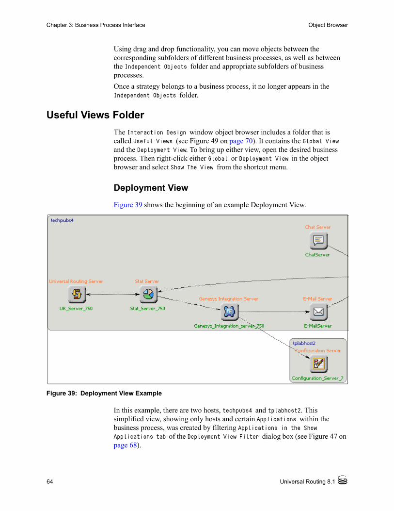
64 Universal Routing 8.1
Chapter 3: Business Process Interface Object Browser
Using drag and drop functionality, you can move objects between the corresponding subfolders of different business processes, as well as between the Independent Objects folder and appropriate subfolders of business processes.
Once a strategy belongs to a business process, it no longer appears in the Independent Objects folder.
Useful Views Folder
The Interaction Design window object browser includes a folder that is called Useful Views (see Figure 49 on page 70). It contains the Global View and the Deployment View. To bring up either view, open the desired business process. Then right-click either Global or Deployment View in the object browser and select Show The View from the shortcut menu.
Deployment View
Figure 39 shows the beginning of an example Deployment View.
Figure 39: Deployment View Example
In this example, there are two hosts, techpubs4 and tplabhost2. This simplified view, showing only hosts and certain Applications within the business process, was created by filtering Applications in the Show Applications tab of the Deployment View Filter dialog box (see Figure 47 on page 68).

Business Process—User’s Guide 65
Chapter 3: Business Process Interface Object Browser
Deployment View shows how various objects in your Configuration Environment are deployed and interact. As shown in Figure 39 on page 64, they are grouped by host. You can print the Deployment View.
Viewing Deployment View Properties
To view the properties for any Application in the Deployment View:, right-click it and click Properties on the shortcut menu. The resulting properties dialog box is read-only. Figure 40 shows an example.
Figure 40: Deployment View, Example Properties for Application
• For an Application object (see Figure 39 on page 64), the dialog box gives the name of the Application, its type, its port number, and the Solutions to which the Application belongs. Figure 41 shows some example Application nodes that you can right-click to bring up a properties dialog box.
Figure 41: Application Object Examples
• For a Switch object, it gives the switch name and type. Figure 42 shows an example Switch node that you can right-click to bring up a properties dialog box.
Figure 42: Switch Object Example

66 Universal Routing 8.1
Chapter 3: Business Process Interface Object Browser
For a Database Access Point, it gives the name of the DAP, its type, its port number, and the Solutions to which it belongs. Figure 43 shows an example Database Access Point node that you can right-click to bring up a properties dialog box.
Figure 43: Database Access Point Example
• For a Host object, it gives the host name, IP address, and operating system.Figure 44 shows an example Host node (mkatten) that you can right-click to bring up a properties dialog box.
Figure 44: Host Object Example
You can also see the settings for the Deployment View as a whole by right-clicking Deployment View in the object browser tree and selecting Properties from the shortcut menu (see Figure 45).
Figure 45: Deployment View Properties Dialog Box

Business Process—User’s Guide 67
Chapter 3: Business Process Interface Object Browser
Changing Deployment View Settings
You might want to change settings. For example, you might want to view only Applications from certain Solutions, only certain types of Applications, or to reduce complexity by not showing unconnected Applications.
To change Deployment View settings:
1. Click right-click Deployment View in the object browser and select Properties from the shortcut menu. This brings up the Deployment View Properties dialog box (see Figure 45 on page 66).
2. Click Define to bring up the dialog box for changing settings (see Figure 46).
Figure 46: Deployment View Filter Dialog Box
• The Show Solutions tab lists all the Solutions that are configured in your Configuration Environment.
• The Show Applications tab lists all the Application types that are configured there. Figure 47 shows an example.
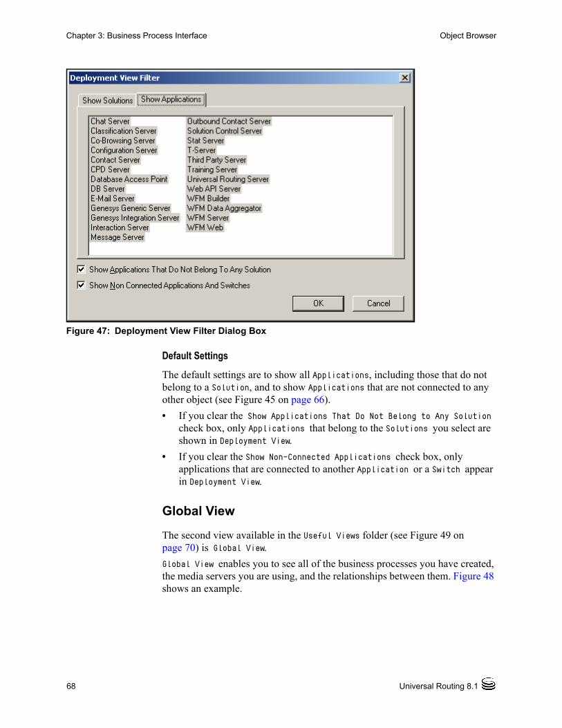
68 Universal Routing 8.1
Chapter 3: Business Process Interface Object Browser
Figure 47: Deployment View Filter Dialog Box
Default Settings
The default settings are to show all Applications, including those that do not belong to a Solution, and to show Applications that are not connected to any other object (see Figure 45 on page 66).
• If you clear the Show Applications That Do Not Belong to Any Solution check box, only Applications that belong to the Solutions you select are shown in Deployment View.
• If you clear the Show Non-Connected Applications check box, only applications that are connected to another Application or a Switch appear in Deployment View.
Global View
The second view available in the Useful Views folder (see Figure 49 on page 70) is Global View.
Global View enables you to see all of the business processes you have created, the media servers you are using, and the relationships between them. Figure 48 shows an example.

Business Process—User’s Guide 69
Chapter 3: Business Process Interface Object Browser
Figure 48: Global View Example
These relationships involve exchanges of interactions. Global View shows the big picture of how interactions are created and handled through the entire workflow sequence. There can be two arrows from one business process to another in the Global View, a red one and a black one. The black one means the business process is passing an existing interaction to the receiving business process. The red one means it is also passing a new interaction.You can open any business process in the Global View by double-clicking it.

70 Universal Routing 8.1
Chapter 3: Business Process Interface Workflow Viewer
Media Servers Folder
By default, the Genesys Multimedia (see page 39) media servers appear as Media Server objects in a Media Servers folder (see Figure 49).
Figure 49: Media Servers Folder
For more information, see “Media Server Object” on page 39. Also see “Using Media Server Objects” on page 252.
Workflow ViewerThe workflow viewer (see Figure 36 on page 61) displays the business process as a directed graph.

Business Process—User’s Guide 71
Chapter 3: Business Process Interface Viewers
• You can drag objects from the object browser and drop them into the viewer.
• You specify the interaction flow by connecting the objects.
• You can reposition the elements as you wish.
• You can have IRD arrange elements in the viewer by choosing Business Process > Arrange Objects.
ViewersThe bottom of the Interaction Design window contains the following three tabs:
• Log
• Configuration Updates
• Search Results
Log Tab
The Log tab displays messages and warnings about business process configuration (see Figure 50).
Figure 50: Log Viewer
The Log tab contains a running log of events that reflect actions that you have taken. The following are more examples:---------------------- Configuration Saving ----------------------Error: Queue2 conflicts with existing Data CollectionConfiguration Saving Abandoned - 1 error(s), 0 warning(s).
Another example:---------------------- Configuration Loading --------------------Warning: View 'Outbound ABC1' was assigned to business process 'ABC Simple BP'Warning: View 'Inbound ABC1' was assigned to business process 'ABC Simple BP' Configuration Loaded - 0 error(s), 2 warning(s).

72 Universal Routing 8.1
Chapter 3: Business Process Interface Viewers
Configuration Updates Tab
The Configuration Updates tab displays the status of changes to the configuration. For example:-------------------------- Connected --------------------------5/24/2004 2:34:47 PM: Queue 'Queue1' has been deleted from configuration server
Search Results Tab
The Search Results tab displays the result of using Find from the Edit menu (see page 79). Figure 51 shows the Search Results tab after using Find.
Figure 51: Search Results Tab
Viewer Context Menus
To clear, hide/unhide or dock the viewers (Log, Configuration Updates, and Search Results), right-click to bring up a context menu in which you can select Hide (see Figure 52).
Note: Interaction Design does not automatically reset values that are modified in Configuration Manager for Queue, View and Workbin objects. When the option values for these objects are changed in Configuration Manager, Interaction Design displays the following message in the Configuration Updates tab:Interaction <object_name' has been changed. If you want to accept these changes, refresh workflow.
In order to save changes that are made in Configuration Manage, you must select Lose the changes and reload configuration in the Refresh Options dialog box.

Business Process—User’s Guide 73
Chapter 3: Business Process Interface File Menu
Figure 52: Viewer Context Menu
To redisplay, select Log from the View menu.
The menu bar (see Figure 36 on page 61) contains File, Edit, View, Business Process, Tools, and Help menus.
File MenuThe File menu contains the commands and keyboard shortcuts that are shown in Figure 53.
Figure 53: File Menu
Refresh Select to reload the Tenant’s configuration information from the Configuration Database. If you made changes and did not save them, you will see the dialog box that is shown in Figure 54.
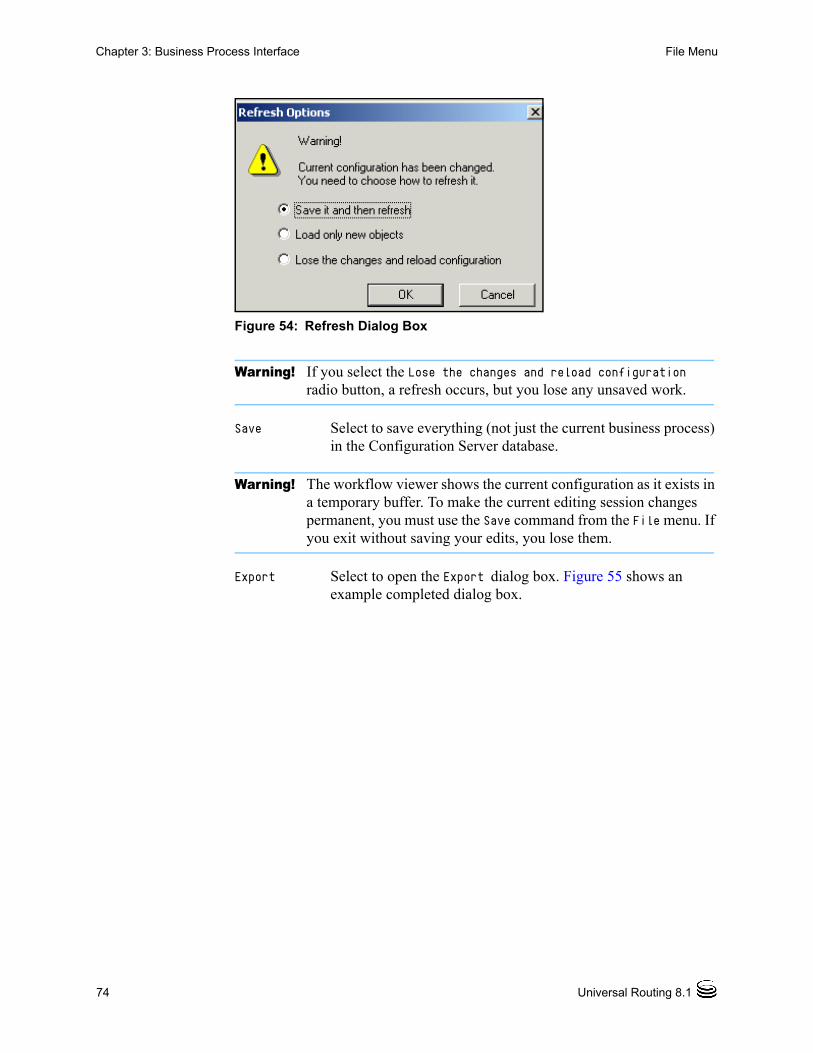
74 Universal Routing 8.1
Chapter 3: Business Process Interface File Menu
Figure 54: Refresh Dialog Box
Warning! If you select the Lose the changes and reload configuration radio button, a refresh occurs, but you lose any unsaved work.
Save Select to save everything (not just the current business process) in the Configuration Server database.
Warning! The workflow viewer shows the current configuration as it exists in a temporary buffer. To make the current editing session changes permanent, you must use the Save command from the File menu. If you exit without saving your edits, you lose them.
Export Select to open the Export dialog box. Figure 55 shows an example completed dialog box.

Business Process—User’s Guide 75
Chapter 3: Business Process Interface File Menu
Figure 55: Export Dialog Box
For more information, see “Exporting a business process” on page 307.
Import Select to open the Configuration Import Wizard. (see Figure 56).

76 Universal Routing 8.1
Chapter 3: Business Process Interface File Menu
Figure 56: Configuration Import Wizard
Use to import a business process that was saved using the Export command For more information, see “Importing a business process” on page 310.
Printing a Business Process
Print, Print Preview, Print Setup
Using these Windows-standard menu selections from the File menu, you can print and print-preview the business process view seen in the Interaction Design window.
Note: To enable Print and Print Preview, first select any object in the business process.
Procedure:Printing large business processes
Purpose: To print a business process that is too large to fit on one page.
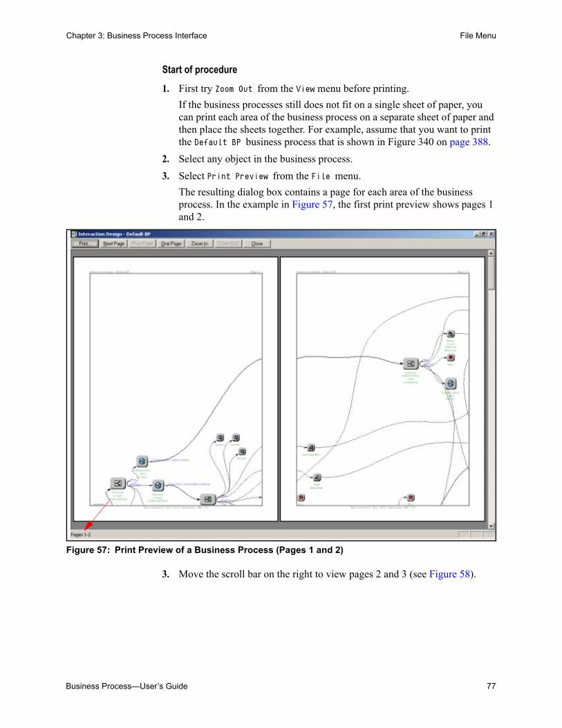
Business Process—User’s Guide 77
Chapter 3: Business Process Interface File Menu
Start of procedure
1. First try Zoom Out from the View menu before printing.
If the business processes still does not fit on a single sheet of paper, you can print each area of the business process on a separate sheet of paper and then place the sheets together. For example, assume that you want to print the Default BP business process that is shown in Figure 340 on page 388.
2. Select any object in the business process.
3. Select Print Preview from the File menu.
The resulting dialog box contains a page for each area of the business process. In the example in Figure 57, the first print preview shows pages 1 and 2.
Figure 57: Print Preview of a Business Process (Pages 1 and 2)
3. Move the scroll bar on the right to view pages 2 and 3 (see Figure 58).

78 Universal Routing 8.1
Chapter 3: Business Process Interface Edit Menu
Figure 58: Print Preview of a Business Process (Pages 2 and 3)
4. Continue moving the scroll bar (or click Next Page in the Print Preview dialog box). You will see that this particular business process encompasses eight pages.
5. Use Zoom In in the Print Preview dialog box to get an enlarged view. This option only prints the current page.
6. Click Print in the Print Preview dialog box that is shown in Figure 57 on page 77.
7. Place the printed pages together to view the entire business process.
8. If necessary, use Namespace Relative (see Figure 73 on page 89) in the Options dialog box to show the manually-edited name of an object, instead of the object’s Script name in the Configuration Database.
End of procedure
The strategy interface has a similar functionality.
Edit MenuNote: You cannot create a copy of a business process or save a business
process under another name.
The Edit menu contains the commands and keyboard shortcuts that are shown in Figure 59.

Business Process—User’s Guide 79
Chapter 3: Business Process Interface Edit Menu
Figure 59: Edit Menu
Note: Menu wording can change depending on the action that is selected.
Undo Switch to Business Process <action>
Redo <action>
This menu item starts out as Undo. Depending on the type of edit you made, this wording changes.
It changes to Undo Creating after you select New <object> from the Business Process menu, but before you edit the item name. Select this option to remove the new item from the object browser so you can start over.
After you delete an object in the workflow viewer, the wording changes to Undo Hide. Selecting this command puts the deleted item back in the viewer.
After you disconnect an object in the workflow viewer, the wording changes to Undo Hide. Selecting this option restores the deleted connection.
Select Redo Updating after using Undo Updating to return to the current edit.
Warning! After selecting any of the preceding commands, save the business process. After you select an Undo or Redo command, the object browser shows the edit, which exists only in a temporary buffer. To make the change permanent, you must save the business process.
Find Brings up the Find dialog box (see Figure 60).

80 Universal Routing 8.1
Chapter 3: Business Process Interface View Menu
Figure 60: Find Dialog Box
For more information on using Find, see “Search Results Tab” on page 72.
View MenuThe View menu contains the commands and keyboard shortcuts that are shown in Figure 61.
Figure 61: View Menu
Object Browser
Select to hide the object browser and enlarge the workflow viewer area. Reselect to redisplay the object browser.
Properties Select an object in the object browser and select Properties to open the properties dialog box for the selected object.
Log Select to hide the log viewer from view. Reselect to redisplay the log viewer.

Business Process—User’s Guide 81
Chapter 3: Business Process Interface View Menu
Toolbar Select to hide the toolbar from view (see Figure 62).
Figure 62: Toolbar
Reselect to redisplay the toolbar.
Status Bar Select to hide the bottom status bar from view. Reselect to redisplay this bar.
Grid Select to remove the grid lines in the workflow viewer and set a white background. Reselect to redisplay the grid.
Page Layout Select to display a page indicator line in the workflow viewer. That line indicates how the workflow viewer display will be divided between pages when you print it.(see Figure 63).
Figure 63: Page Layout Indicator
Zoom In Select to magnify the objects in the workflow viewer.
Zoom Out Select to return to the previous magnification. Useful when printing.
indicator line
page layout

82 Universal Routing 8.1
Chapter 3: Business Process Interface Business Process Menu
Zoom Normal Select after using Zoom In more than once to immediately return objects to normal viewing size.
Business Process MenuThe Business Process menu (when you click inside the object browser) contains the selections and keyboard shortcuts that are shown in Figure 64.
Figure 64: Business Process Menu
Note: If the selections appear inactive, click inside the object viewer.
New Business Process
Select to add a new business process. IRD assigns a temporary name, which you can change (see Figure 196 on page 249).
New Queue Select to define a new Queue object. IRD assigns a temporary name, which you can change (see Figure 205 on page 258).
New View Select to define a new View object (see Figure 219 on page 269). Enabled only when a queue is selected in the workflow viewer or the object browser. IRD assigns the new view a temporary name, which you can change (see Figure 219 on page 269), and attaches the new view to the selected queue.
New Strategy Select to define a new routing strategy. See “Strategy Placeholder Option” on page 299.
New Workbin Select to define a new Workbin object. IRD assigns a temporary name, which you can change (see Figure 244 on page 294).
Add Endpoint Select to define a new Endpoint object (see Figure 24 on page 40). Enabled only when a media server is selected in the object browser.
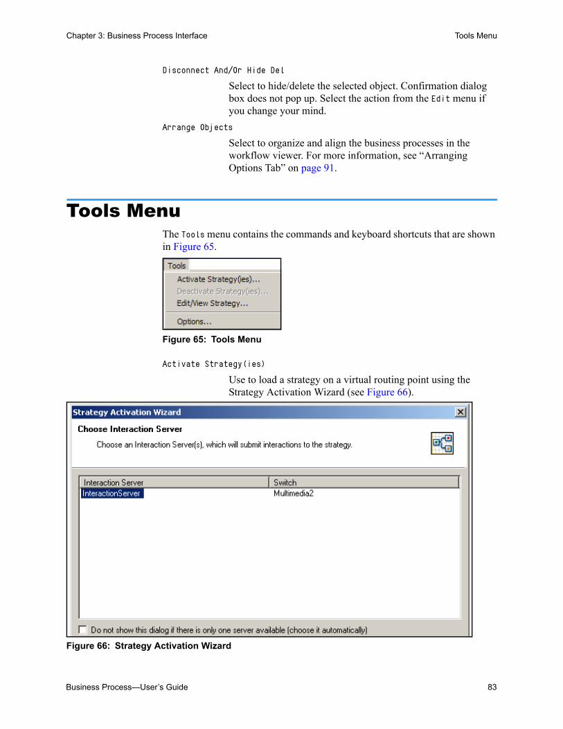
Business Process—User’s Guide 83
Chapter 3: Business Process Interface Tools Menu
Disconnect And/Or Hide Del
Select to hide/delete the selected object. Confirmation dialog box does not pop up. Select the action from the Edit menu if you change your mind.
Arrange Objects
Select to organize and align the business processes in the workflow viewer. For more information, see “Arranging Options Tab” on page 91.
Tools MenuThe Tools menu contains the commands and keyboard shortcuts that are shown in Figure 65.
Figure 65: Tools Menu
Activate Strategy(ies)
Use to load a strategy on a virtual routing point using the Strategy Activation Wizard (see Figure 66).
Figure 66: Strategy Activation Wizard

84 Universal Routing 8.1
Chapter 3: Business Process Interface Tools Menu
The Wizard provides a convenient way to create a virtual routing point on the Switch object for the purpose of loading/activating a multimedia routing strategy (see Figure 67). To distinguish the virtual routing points automatically created for multimedia strategies through the Wizard, their names will combine the prefix asl and the name of the strategy: asl_ <strategy_name>. asl stands for active strategy loading.
Figure 67: Strategies Loaded on Virtual Routing Points in Loading View
The Wizard requires that the Interaction Server specify a Switch connection (see Figure 320 on page 362). If such a connection does not exist, the Wizard displays a message to this effect.
• For more information, see “Activating Strategies” on page 361.
This section continues with the next item on the Tools menu (see Figure 65 on page 83).
Deactivate Strategy (ies)
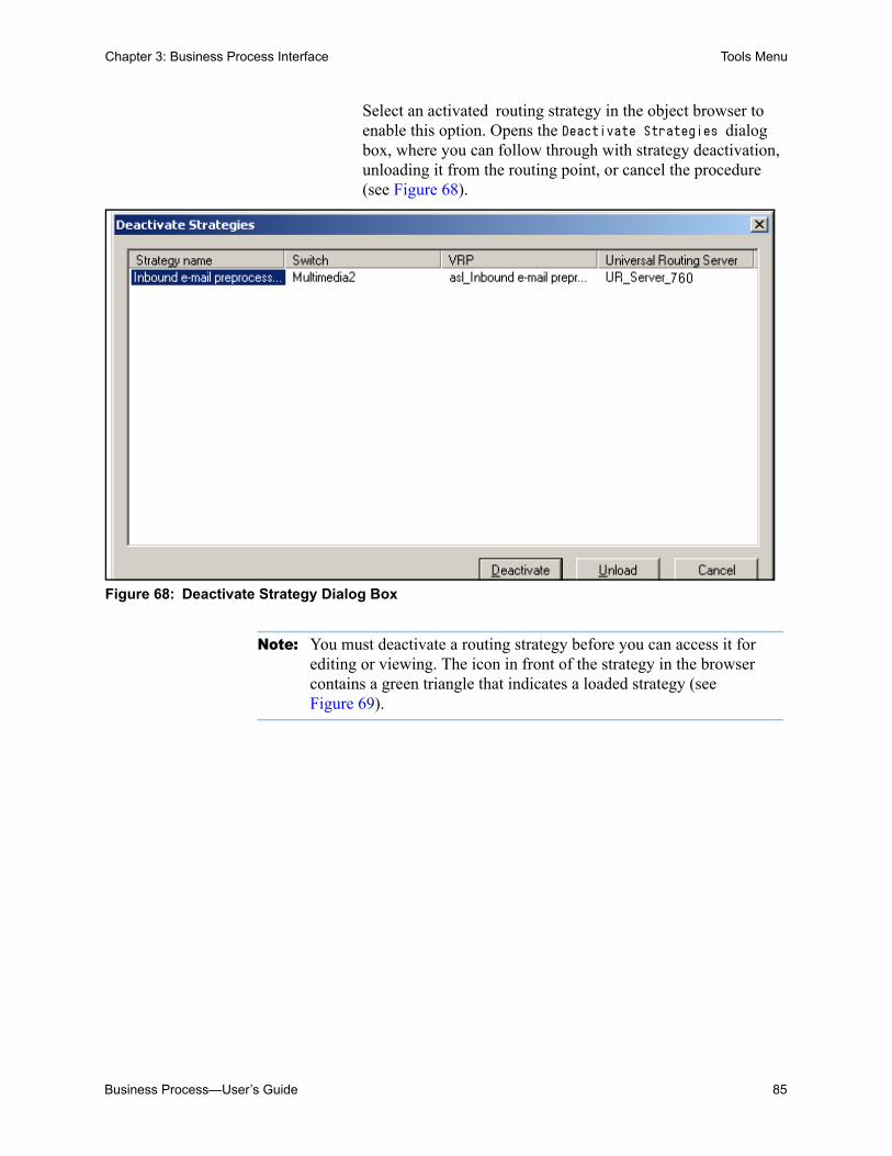
Business Process—User’s Guide 85
Chapter 3: Business Process Interface Tools Menu
Select an activated routing strategy in the object browser to enable this option. Opens the Deactivate Strategies dialog box, where you can follow through with strategy deactivation, unloading it from the routing point, or cancel the procedure (see Figure 68).
Figure 68: Deactivate Strategy Dialog Box
Note: You must deactivate a routing strategy before you can access it for editing or viewing. The icon in front of the strategy in the browser contains a green triangle that indicates a loaded strategy (see Figure 69).

86 Universal Routing 8.1
Chapter 3: Business Process Interface Tools Menu
Figure 69: Loaded and Unloaded Strategies in Object Browser
Edit/View Strategy...
Select a routing strategy in the object browser to enable this Tools menu option. Opens the selected strategy for editing.
If the strategy is already loaded, the menu item is Deactivate Strategy(ies), which automatically removes the corresponding virtual routing point along and unloads the strategy.
Options Select to open the Options dialog box. (see Figure 70).
Figure 70: Options Dialog Box, Configuration Tab
The following options are available from the Configuration tab of the Options dialog box.
Configuration Tab
Fix Referential Integrity Errors Automatically (on load)
loaded strategies
unloaded strategy

Business Process—User’s Guide 87
Chapter 3: Business Process Interface Tools Menu
Enable this option to allow IRD to assign configuration objects (such as Queue, View, Submitter, and Strategy objects) to the same business process, when it judges, during its initial loading, that referential integrity has been changed.
Disable (clear) this option to forbid the automatic corrections described above. During loading, IRD notifies you of possible problems and you must respond manually. Choose if you want to preserve intentional changes.
Remove Unused Submitters from Configuration (on save)
If you make changes outside IRD (for example, in Configuration Manager) a Submitter (see Figure 23 on page 39) in IRD may become disconnected—and invisible to the user. When you bring up the business process, you will see a “Submitter” is ignored... message in the log viewer if this has happened.
Enable this option to allow IRD to automatically remove Submitter objects that are invisible and disconnected. Notification of an automatic removal appears in the log viewer.
Disable this option to prevent this automatic removal of Submitters.
Appearance Tab
This section discusses the Appearance tab in the Options dialog box (see Figure 71).

88 Universal Routing 8.1
Chapter 3: Business Process Interface Tools Menu
Figure 71: Options Dialog Box, Appearance Tab
Labels The on/off buttons in front of Namespace Relative, Real Configuration Names, and Both allow objects to have one name in the Interaction Design window, but a different name in the Configuration Database, a feature which can be very useful when you are designing complicated business processes.
For technical background information on this feature, see “Workflow Object Names” on page 171.
Real Configuration Names
Select to have the browser or viewer show the object’s Script name. Assume that you define a queue that is named Inbound e-mails1, a view named Inbound e-mails2, save the definitions as Script objects in the Configuration Database, and then select the Real Configuration Names button as shown in Figure 71 on page 88. The objects appear with their Configuration Database Script names as shown in Figure 72.

Business Process—User’s Guide 89
Chapter 3: Business Process Interface Tools Menu
Figure 72: Real Configuration Names
Namespace Relative
Select to have the Interaction Design window show the result of manually editing a queue, view, or workbin name in the browser or viewer after the initial save as a Script object in the Configuration Database.
Assume that you edit the names that are shown in Figure 72 and use the same name (Inbound e-mails) for both the queue and its view (which Configuration Server does not allow for Script objects). If you select the Namespace Relative button as shown in Figure 71 on page 88, the objects appear as shown in Figure 73.
Figure 73: Namespace Relative
Both Select to show both the decorative and internal Script name (with the internal name in parentheses).
If you select Both in Figure 71 on page 88, the objects appear as shown in Figure 74.
Figure 74: Both (Namespace Relative and Real Configuration Names)

90 Universal Routing 8.1
Chapter 3: Business Process Interface Tools Menu
Accurate Printing
When you are printing a business process that contains overlapping objects, use this option (see Figure 71 on page 88) to ensure that all object detail prints and tiny white spaces do not occur.
Workflow Settings Tab
This section discusses the third tab in the Options dialog box, Workflow Settings (see Figure 75).
Figure 75: Options Dialog Box, Workflow Settings Tab
Targets
Enable to have the business process show routing strategy targets as strategy-linked nodes (see “Strategy-Linked Nodes” on page 34 and Figure 20 on page 37).
Servers
Enable to have the business process show routing strategy actions (such as those performed by servers) as strategy-linked nodes (see “Strategy-Linked Nodes” on page 34 and Figure 19 on page 36).
Stops
Enable to have the business process show routing strategy Stop Interaction objects as strategy-linked nodes (see “Strategy-Linked Nodes” on page 34).

Business Process—User’s Guide 91
Chapter 3: Business Process Interface Tools Menu
Edges To Subroutines
Enable to remove lines showing connections from strategies to subroutines. Doing so reduces the complexity of the layout, making it easier to interpret.
Arranging Options Tab
When you select Arrange from the Business Process menu, IRD uses an algorithm that arranges nodes in the workflow viewer based on what you enter in the Arranging Options tab (see Figure 76).
Figure 76: Options Dialog Box, Arranging Options Tab
The fields in the Arranging Options tab (see Figure 76 on page 91) are summarized below.
Accounting for Labels
IRD places labels above nodes (type) and below nodes (name) nodes as well as on the right of nodes (for names of views) . The end result of the arranging algorithm produces compact picture, but some labels may overlap. You can fix this by checking the Horizontal and Vertical fields in the Arranging Options tab.
Horizontal By checking the Horizontal checkbox, you are instructing IRD to account for horizontal dimension of labels in its arranging algorithm. In this case, IRD includes the horizontal positions of labels into the node size calculation, which spreads the nodes out more horizontally.
Vertical By checking Vertical checkbox, you are instructing IRD to account for the vertical dimension of labels in its arranging algorithm. In this case, IRD includes the vertical positions of

92 Universal Routing 8.1
Chapter 3: Business Process Interface Tools Menu
labels into the node size calculation, which spreads the nodes out more vertically.
Notes: Each rectangular node has a height and width. The default node sizes are 48x48 (for queue nodes), 64x48 (for strategy and media server nodes), and 32x32 (for stop, server and agent nodes). If you don’t check either of the Accounting for Labels checkboxes, IRD defaults to these sizes.
If the Horizontal and Vertical boxes are both checked, the size of almost every node will be different (because labels usually have bigger dimensions than nodes). This spreads out the nodes and produces a nice looking picture, but of much bigger size.
Spacing Between Ranks (pixels)
Use this field to specify the separation of nodes in adjacent ranks. Allows you to adjust the spacing of nodes by setting the number of pixels between one column of nodes and the column of nodes beside it. Enter any number between 16 and 160.
For a definition of rank, see “Arranging Algorithm” below.
Spacing Inside Rank (pixels)
Use to specify the separation of nodes inside a rank. Allows you to adjust the spacing of nodes by setting the number of pixels between nodes in a single column. Enter any number between 16 and 96.
Arranging Algorithm
When arranging nodes, the arranging algorithm:
• First assigns ranking numbers. Rank number assignment depends on the relationship between nodes or, more specifically, it depends on edges between the nodes.
If two nodes are connected at an edge, the source of the edge will have a lesser rank than the destination edge. For example, assume:
You have nodes A, B, C and D.
The edge of A is connected to the edge of B.
The edge of A is also connected to the edge of C.
The edge of B is connected to the edge of D.
In this case, the algorithm assigns a ranking of 0 for A, 1 for B and C, and 2 for D.
• After assigning rank numbers, the algorithm arrange nodes in ranks (levels) in order to minimize edge crossing. Sometimes changing nodes in a rank will lower edge crossing between nodes in adjacent ranks.

Business Process—User’s Guide 93
Chapter 3: Business Process Interface Help Menu
• Finally, after the relative positions between nodes is calculated (when it is known which node is left, which node is right, which node is above and below, and so on), the algorithm gives exact positions to nodes. In this step it uses the size of nodes and the specified amount of space between nodes of adjacent ranks and between adjacent nodes in same rank.
Help MenuThe Help menu contains the commands and keyboard shortcuts that are shown in Figure 77.
Figure 77: Help Menu
Help Topics
Displays the Universal Routing 8.1 Interaction Routing Designer Help.
About IRD
Displays a dialog box containing the Genesys logo, the software title, version number, copyright notice, and warning.
Shortcut MenusFigure 78 shows an example shortcut menu when you right-click a business process in the object browser (not in the currently open business process).
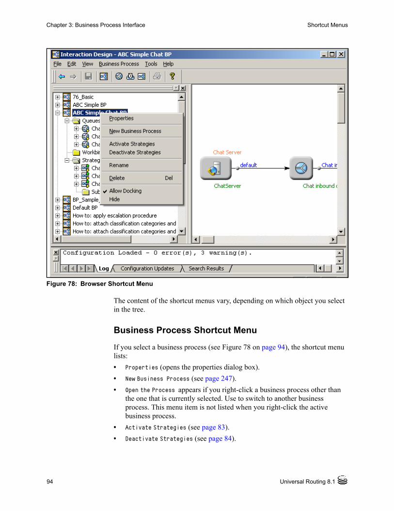
94 Universal Routing 8.1
Chapter 3: Business Process Interface Shortcut Menus
Figure 78: Browser Shortcut Menu
The content of the shortcut menus vary, depending on which object you select in the tree.
Business Process Shortcut Menu
If you select a business process (see Figure 78 on page 94), the shortcut menu lists:
• Properties (opens the properties dialog box).
• New Business Process (see page 247).
• Open the Process appears if you right-click a business process other than the one that is currently selected. Use to switch to another business process. This menu item is not listed when you right-click the active business process.
• Activate Strategies (see page 83).
• Deactivate Strategies (see page 84).
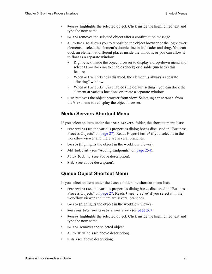
Business Process—User’s Guide 95
Chapter 3: Business Process Interface Shortcut Menus
• Rename highlights the selected object. Click inside the highlighted text and type the new name.
• Delete removes the selected object after a confirmation message.
• Allow Docking allows you to reposition the object browser or the log viewer elements—select the element’s double line in its header and drag. You can dock an element at different places inside the window, or you can allow it to float as a separate window. Right-click inside the object browser to display a drop-down menu and
select Allow Docking to enable (check) or disable (uncheck) this feature.
When Allow Docking is disabled, the element is always a separate “floating” window.
When Allow Docking is enabled (the default setting), you can dock the element at various locations or create a separate window.
• Hide removes the object browser from view. Select Object Browser from the View menu to redisplay the object browser.
Media Servers Shortcut Menu
If you select an item under the Media Servers folder, the shortcut menu lists:
• Properties (see the various properties dialog boxes discussed in “Business Process Objects” on page 27). Reads Properties of if you select it in the workflow viewer and there are several branches.
• Locate (highlights the object in the workflow viewer).
• Add Endpoint (see “Adding Endpoints” on page 254).
• Allow Docking (see above description).
• Hide (see above description).
Queue Object Shortcut Menu
If you select an item under the Queues folder, the shortcut menu lists:
• Properties (see the various properties dialog boxes discussed in “Business Process Objects” on page 27. Reads Properties of if you select it in the workflow viewer and there are several branches.
• Locate (highlights the object in the workflow viewer).
• New View lets you create a new view (see page 267).
• Rename highlights the selected object. Click inside the highlighted text and type the new name.
• Delete removes the selected object.
• Allow Docking (see above description).
• Hide (see above description).
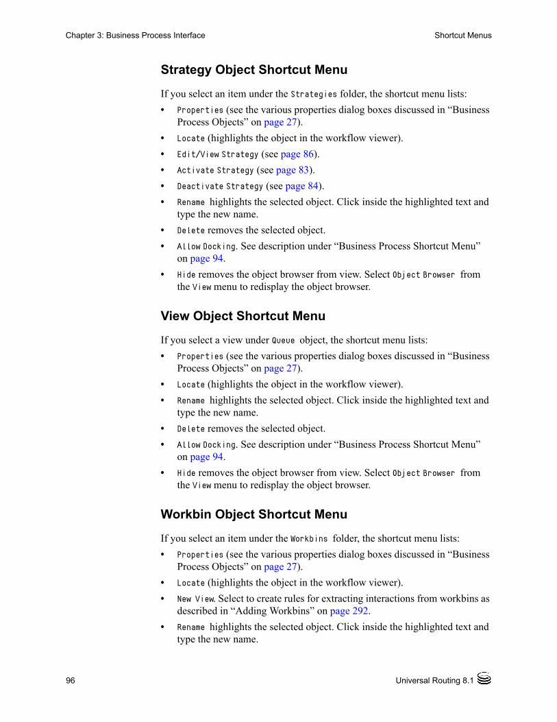
96 Universal Routing 8.1
Chapter 3: Business Process Interface Shortcut Menus
Strategy Object Shortcut Menu
If you select an item under the Strategies folder, the shortcut menu lists:
• Properties (see the various properties dialog boxes discussed in “Business Process Objects” on page 27).
• Locate (highlights the object in the workflow viewer).
• Edit/View Strategy (see page 86).
• Activate Strategy (see page 83).
• Deactivate Strategy (see page 84).
• Rename highlights the selected object. Click inside the highlighted text and type the new name.
• Delete removes the selected object.
• Allow Docking. See description under “Business Process Shortcut Menu” on page 94.
• Hide removes the object browser from view. Select Object Browser from the View menu to redisplay the object browser.
View Object Shortcut Menu
If you select a view under Queue object, the shortcut menu lists:
• Properties (see the various properties dialog boxes discussed in “Business Process Objects” on page 27).
• Locate (highlights the object in the workflow viewer).
• Rename highlights the selected object. Click inside the highlighted text and type the new name.
• Delete removes the selected object.
• Allow Docking. See description under “Business Process Shortcut Menu” on page 94.
• Hide removes the object browser from view. Select Object Browser from the View menu to redisplay the object browser.
Workbin Object Shortcut Menu
If you select an item under the Workbins folder, the shortcut menu lists:
• Properties (see the various properties dialog boxes discussed in “Business Process Objects” on page 27).
• Locate (highlights the object in the workflow viewer).
• New View. Select to create rules for extracting interactions from workbins as described in “Adding Workbins” on page 292.
• Rename highlights the selected object. Click inside the highlighted text and type the new name.

Business Process—User’s Guide 97
Chapter 3: Business Process Interface Shortcut Menus
• Delete removes the selected object.
• Allow Docking. See description under “Business Process Shortcut Menu” on page 94.
• Hide removes the object browser from view. Select Object Browser from the View menu to redisplay the object browser.
Workflow Viewer Shortcut Menus
The menu items that are listed depend on whether an object is selected.
Object Not Selected
If you right-click inside the workflow viewer without selecting an object, the shortcut menu lists:
• New has branches for adding a new queue, workbin, or strategy.
• Grid (hides/shows workflow viewer grid lines).
• Page Layout (hides/shows workflow viewer page break indicator).
• Zoom In (magnifies icons in workflow viewer).
• Zoom Out (moves workflow viewer display away from icons).
• Zoom Normal (sets workflow viewer to normal zoom).
Object Selected
If you right-click an object inside the workflow viewer, the shortcut menu lists:
• Properties of if a Queue or Media Server object is selected. There are Queue and View branches.
• Reads Properties if a Strategy object is selected.
• Reads Add Endpoint if a Media Server object is selected.
• Locate (highlights the object in the Workflow Viewer).
• Edit/View Strategy if a Strategy object is selected.
• Activate or Deactivate Strategy if a Strategy object is selected.
• New View if a Queue or View object is selected.
• Disconnect and/or Hide if a Queue object is selected.
• Grid (hides/shows workflow viewer grid lines).
• Page Layout (hides/shows workflow viewer page break indicator).
• Zoom In (magnifies icons in workflow viewer).
• Zoom Out (moves workflow viewer display away from icons).
• Zoom Normal (sets workflow viewer to normal zoom).
• Bring Forward changes the position (brings forward) of the selected object relative to the others in the stack. Use for overlapping objects.

98 Universal Routing 8.1
Chapter 3: Business Process Interface Shortcut Menus
• Send Back changes the position (sends back) of the selected object relative to the others in the stack. Use for overlapping objects.
• Label/Group for any group of objects or object selected. See “Grouping and Labels” section below.
Grouping and Labels
You can create a group of objects within a business process and then label it. This enables you to mark out a set of objects that have something in common. Figure 79 shows an example.
Figure 79: Labeled Group of Objects
Procedure:Grouping objects within a business process
Purpose: To group together a set of objects within a business process either for visual purposes or to apply the same set of properties to the group.
Start of procedure
1. Select the objects to group by clicking each one as you hold down the [Ctrl] key. Or hold down the mouse button and select the entire group with the mouse cursor so they all appear highlighted.
2. Right-click any of the selected objects and select Label/Group from the shortcut menu. The Group Properties dialog box opens (see Figure 80).

Business Process—User’s Guide 99
Chapter 3: Business Process Interface Shortcut Menus
Figure 80: Group Properties Dialog Box
3. Type the label text into the Label text box.
4. Optionally, you can also perform other operations: You can have the group set off by a border by selecting Has Border.
This check box is selected by default. If you want the text to wrap, select Multiline. This check box is
selected by default. To have the group actually handled and arranged as a unit, select the
Subgraph check box. When you select Subgraph, Has Border is also selected automatically.
To Align, select the radio buttons that set the label where you want it. You can select either Left or Center and either Top or Bottom. Top and Left are selected by default.
5. When through in the dialog box, click OK. The new group, with its label, appears in the workflow viewer.
• To remove an object from a group, right-click the object and select Remove from Group from the shortcut menu. To remove a group, you must remove all the objects from the group.
• To change the properties of a group, right-click the group label and select Properties from the shortcut menu.
• To add an object to a group, create a new group that includes all the objects you want grouped.
End of procedure

100 Universal Routing 8.1
Chapter 3: Business Process Interface Interaction Design Shortcut Bar
Note: You cannot put an object into more than one group. You cannot create nested groups (where one group contains another group).
Viewer Context Menus
The Log, Configuration Update, and Search Result tabs in the lower portion of the Interaction Design window also bring up context menus. See Figure 52 on page 73.
Interaction Design Shortcut BarWhen IRD starts up, it checks for an eServices (formerly, Multimedia) solution that was installed by the Multimedia Configuration Wizard. If one is not found, the main IRD window or the window that is shown in Figure 35 on page 60 does not display an Interaction Design shortcut bar and you cannot open the Interaction Design window (shown in Figure 36).
Use the following workaround if Multimedia components were manually configured in the Configuration Database without using the Wizard or if the Interaction Design shortcut bar does not display.
Procedure:Displaying the Interaction Design shortcut bar
Start of procedure
1. Log into IRD as described on page 57.
2. Click to Tools menu and select Routing Design Options.
3. Click the Views tab in the IRD Options dialog box.
4. Uncheck the Default check box.
5. Verify that the following are checked: • Interaction Design• Business Processes
6. Click OK to save your changes.
End of procedure

Business Process—User’s Guide 101
Chapter 3: Business Process Interface Interaction Design Shortcut Bar
Summary
The intent of this chapter is to introduce the business process interface. For step-by-step instructions on using the interface, see “Creating Business Process Objects” on page 247.

102 Universal Routing 8.1
Chapter 3: Business Process Interface Interaction Design Shortcut Bar

Business Process—User’s Guide 103
Chapter
4 Strategy InterfaceThis chapter describes the interface for creating routing strategies that are contained within business processes. Find step-by-step instructions for creating routing strategies on page 323.
This chapter includes the following sections: Shortcut Bars in IRD Main Window, page 104 IRD Menus, page 106 Reusable Objects, page 115 Strategy-Building Objects, page 122 Routing Design Toolbar, page 123 Using the Strategy-Building Objects, page 129 Properties Dialog Boxes, page 132 Building Logical Expressions, page 135 Comment Object, page 139 Other Design View Operations, page 140 Routing Design Options, page 142 Database Wizard, page 147 Defining Variables, page 150 IRD Security, page 152
Note: The information in this section assumes that you have already installed IRD, as described in the Universal Routing 8.1 Deployment Guide.
Start IRD, as described on page 58. After you complete the login fields, click OK, the Strategies list pane opens (see Figure 34 on page 59).
The remainder of this chapter discusses strategy interface elements, both in the IRD main window and in the Routing Design window.

104 Universal Routing 8.1
Chapter 4: Strategy Interface Shortcut Bars in IRD Main Window
Shortcut Bars in IRD Main WindowNote the shortcut bars in Figure 34 on page 59. The shortcut bars access the various views and objects of IRD.
• Clicking the Interaction Design shortcut bar in Figure 34 on page 59 displays a Business Processes icon on the left. Clicking this icon brings up the Business Process list pane (see Figure 35 on page 60).
• Clicking the Routing Design shortcut bar and then a reusable object icon on the left displays that object’s list pane. For examples, see Figure 91 on page 116 and Figure 92 on page 116.
• Clicking Event Log followed by Event Viewer brings up Event Log view where you can see the history of your actions in IRD (see Figure 81).
Figure 81: Event Log
For log location, see Working Directory (Figure 133 on page 145).
• Clicking Monitoring displays the Loading and Group Loading icons.
Clicking Loading brings up Loading view. Here you can view routing points (including virtual routing points) and the names of strategies loaded on those routing points (see Figure 67 on page 84).
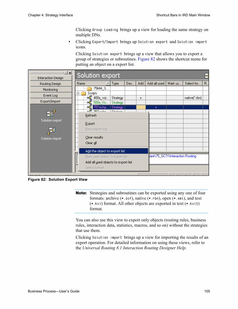
Business Process—User’s Guide 105
Chapter 4: Strategy Interface Shortcut Bars in IRD Main Window
Clicking Group Loading brings up a view for loading the same strategy on multiple DNs.
• Clicking Export/Import brings up Solution export and Solution import icons.
Clicking Solution export brings up a view that allows you to export a group of strategies or subroutines. Figure 82 shows the shortcut menu for putting an object on a export list.
Figure 82: Solution Export View
Note: Strategies and subroutines can be exported using any one of four formats: archive (*.zcf), native (*.rbn), open (*.xml), and text (*.kvl) format. All other objects are exported in text (*.kvlt) format.
You can also use this view to export only objects (routing rules, business rules, interaction data, statistics, macros, and so on) without the strategies that use them.
Clicking Solution import brings up a view for importing the results of an export operation. For detailed information on using these views, refer to the Universal Routing 8.1 Interaction Routing Designer Help.

106 Universal Routing 8.1
Chapter 4: Strategy Interface IRD Menus
IRD MenusNote: The menus below are available in IRD when not working in the
Interaction Design window (see Figure 36 on page 61).
The following menus are available in the IRD main window: File, Edit, View, Tools, and Help. The current view controls what menu items and enabled and disabled. The enabled menu items that are shown in Figure 83 are those that are available when you click the Strategy Design shortcut followed by the Strategies icon, which displays the Strategies list pane (see Figure 34 on page 59).
File Menu
The File menu contains the commands and keyboard shortcuts that are shown in Figure 83.
Figure 83: File Menu
The File menu includes the following commands:
New Creates a new object based on the current view.
Note: In order to enable New, you must first select a folder for the reusable object on the list pane.

Business Process—User’s Guide 107
Chapter 4: Strategy Interface IRD Menus
Open Opens the selected object. If you select Open when a strategy is selected, the Routing Design window opens. When other types of objects are selected (subroutine, routing rule, business rule, attribute, interaction data), the corresponding dialog box opens.
Close Enabled when in the Routing Design window. Closes only the Routing Design window.
Save If you are creating a new strategy in the Routing Design window, selecting Save from the File menu opens the Save dialog box (see Figure 84).
Figure 84: Save Dialog Box
Here you can specify the .rbn file save location (see “Graphical Portion of a Strategy” on page 172). The Script object save location is the Scripts folder you specify in the list pane in order to enable New from the File menu.
Note: If you are editing an existing strategy and select Save from the File menu, the save action occurs, but the Save dialog does not appear.
Save As Enabled in Routing Design window. Opens the Save As dialog box where you have the option of changing the name and/or storage location for the .rbn file and Script object in the Scripts folder of Configuration Manager.
Describe Enabled in Routing Design window. Opens the Describe dialog box where you can add or change the description of a strategy or subroutine or the input/output parameters of a subroutine (see Figure 85).

108 Universal Routing 8.1
Chapter 4: Strategy Interface IRD Menus
Figure 85: Describe Dialog Box
Backup Enabled in the Routing Design window. Backs up the current strategy by creating a version.
Restore Enabled in the Routing Design window. Restores one of the backup versions of a strategy. You can select which version to restore.
Restore from temp
Enabled in the Routing Design window. Restores a strategy saved by IRD when the Autosave timer feature is activated (see Figure 133 on page 145).
Export to File
Exports a strategy that you have selected in the Strategies list pane. For another person to view a strategy you have created, they must have access to both the Script file and the .rbn file (see “Graphical Portion of a Strategy” on page 172). For more information, see the section on automatically packaging a strategy in Universal Routing 8.1 Reference Manual.
Import From File
Imports a strategy file and creates a Script object for a strategy and its subroutines (if any), business rules, routing rules, attributes, interaction data, statistics, list objects, and macros in the Configuration Layer for the strategy. For more information, see the section on importing a strategy file in Universal Routing 8.1 Reference Manual.
Print, Print Preview, Page Setup
Using these Windows-standard menu selections, you can print and print-preview the strategy view seen in the Routing Design

Business Process—User’s Guide 109
Chapter 4: Strategy Interface IRD Menus
window. You can print to a PDF file if you have the appropriate print driver installed.
When printed, some strategies may not fit on a single sheet of paper. In this case, you can print each area of the strategy on a separate sheet of paper, and then place the sheets together. For example, assume that you want to print the Classify customer inquiry att-ct strategy that is shown in Figure 357 on page 414.
Procedure:Printing large strategies
Start of procedure
1. Open the strategy.
2. Select Print Preview from the File menu. The resulting dialog box contains a page for each area of the strategy. The print preview example in Figure 86 shows the strategy on two pages.
Figure 86: Print Preview of a Strategy (Pages 1 and 2)
3. If the strategy exceeds two pages, move the scroll bar (or click Next Page in the Print Preview dialog box) to view the remaining pages.

110 Universal Routing 8.1
Chapter 4: Strategy Interface IRD Menus
Note: Use Zoom In in the Print Preview dialog box to get an enlarged view. This option only prints the current page. Use Zoom Out to fit more on a page.
4. Click Print in the Print Preview dialog box that is shown in Figure 86 on page 109.
Note: To avoid printing blank pages, in the Print dialog box, specify the To and From pages .
5. Place the printed pages together to view the entire strategy. In the Print dialog box, specify the to and from pages.
6. To get a better idea of interaction flow before printing, use Comment objects (see page 139) or manipulate Graph Settings in the Routing Design Options dialog box (see Figure 127 on page 142).
End of procedure
This section now continues with the next item on the File menu, Change Password.
Change Password
Brings up a dialog box that allows you to change your password, which is used to gain access to GUI applications.
Exit Exits IRD if used in the IRD main window. Closes the opened strategy if used in the Routing Design window. If there are any unsaved changes in the current strategy, a confirmation dialog box prompts you to save those changes.
Edit Menu
The Edit menu contains the commands and keyboard shortcuts that are shown in Figure 87.
Figure 87: Edit Menu
This menu includes the following commands:
Undo Reverses the last action. This command is not available for all actions.
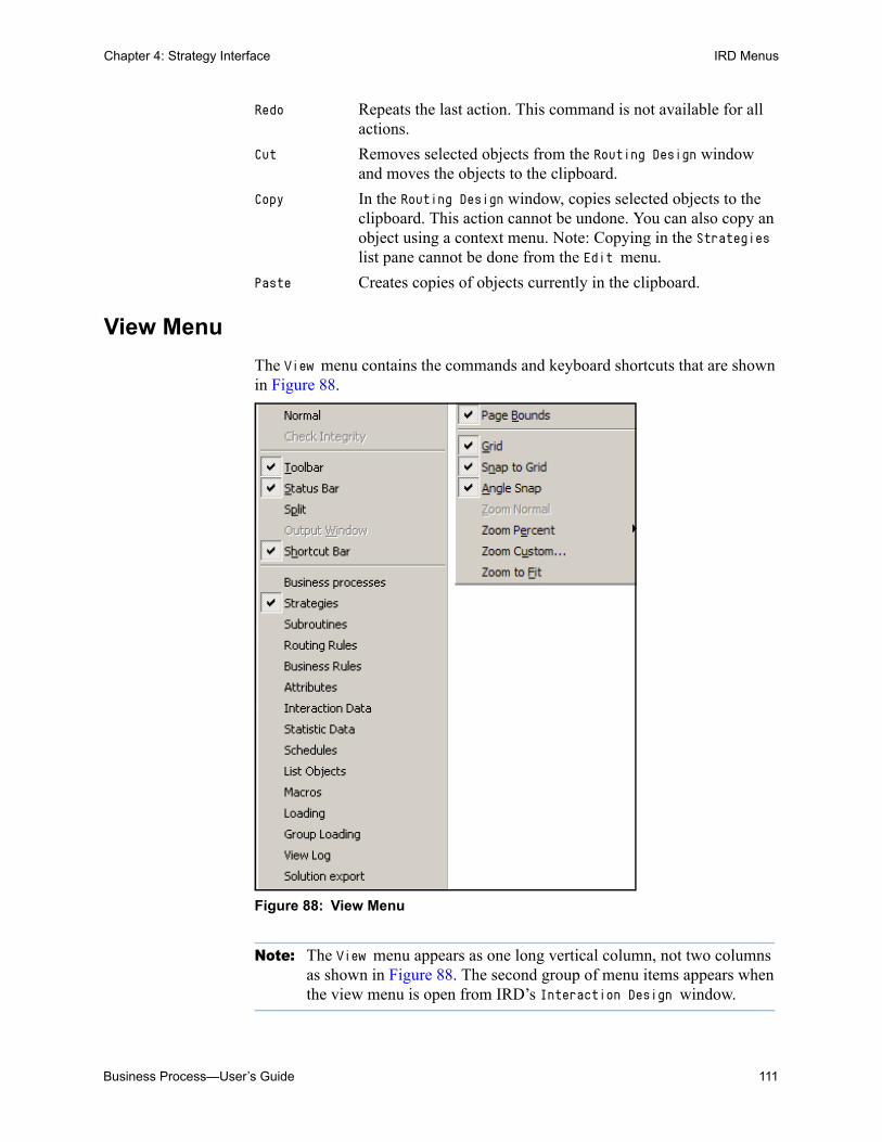
Business Process—User’s Guide 111
Chapter 4: Strategy Interface IRD Menus
Redo Repeats the last action. This command is not available for all actions.
Cut Removes selected objects from the Routing Design window and moves the objects to the clipboard.
Copy In the Routing Design window, copies selected objects to the clipboard. This action cannot be undone. You can also copy an object using a context menu. Note: Copying in the Strategies list pane cannot be done from the Edit menu.
Paste Creates copies of objects currently in the clipboard.
View Menu
The View menu contains the commands and keyboard shortcuts that are shown in Figure 88.
Figure 88: View Menu
Note: The View menu appears as one long vertical column, not two columns as shown in Figure 88. The second group of menu items appears when the view menu is open from IRD’s Interaction Design window.

112 Universal Routing 8.1
Chapter 4: Strategy Interface IRD Menus
Normal When this command is selected, the Check Integrity tool (see page 354) is de-activated. This is the default setting. The Normal command functions with the Check Integrity command to de-activate/activate the Check Integrity tool.
Check Integrity
When this command is selected, the Check Integrity tool is activated (see page 354. When activated, all strategies and objects in IRD are checked with the exception of objects used in the object browser of the Interaction Design window (see page 62). As IRD performs the check, no other operation can be performed. The progress bar indicates the progress of the integrity checking.
Toolbar Displays/hides the toolbar.
Status Bar Displays/hides the status bar.
Split Splits the active window with a horizontal divider.
Output Window
When a strategy is open, displays the an output area that contains the Find in Strategy and Errors in Strategy tabs. These tabs appear automatically when compiling or checking integrity.
Shortcut Bar Displays/hides the shortcut bars (see page 104).
Strategies Displays the Strategies list pane (see Figure 34 on page 59). The Strategies list may also be displayed by selecting the Strategies icon on the shortcut bar.
Subroutines Displays the Subroutines (see page 117) list. The Subroutines list may also be displayed by selecting the Subroutines icon on the shortcut bar.
Routing Rules Displays the Routing Rules (see page 117) list. The Routing Rules list may also be displayed by selecting the Routing Rules icon on the shortcut bar.
Business Rules
Displays the Business Rules (see page 119) list. The Business Rules list may also be displayed by selecting the Business Rules icon on the shortcut bar.
Attributes Displays the Attributes (see page 118) list. The Attributes view may also be displayed by selecting the Attributes icon on the shortcut bar.
Interaction Data
Displays the Interaction Data (see page 119) list. The Interaction Data list may also be displayed by selecting the Interaction Data icon on the shortcut bar.

Business Process—User’s Guide 113
Chapter 4: Strategy Interface IRD Menus
Statistic Data
Displays the Statistics (see page 120) list. The Statistics list may also be displayed by selecting the Statistics icon on the shortcut bar.
Schedules Displays the Schedules (see page 120) list. The Schedules list may also be displayed by selecting the Schedules icon on the shortcut bar.
List Objects Displays the List Objects (see page 121) list. The list may also be displayed by selecting the List Objects icon on the shortcut bar.
Macros Displays the Macros (see page 121) list. The Macros list may also be displayed by selecting the Macros icon on the shortcut bar.
Loading Displays the Loading view (see Figure 67 on page 84). The Loading view may also be displayed by selecting the Loading icon on the shortcut bar.
Group Loading Displays the Group Loading (see page 104) view. The Group Loading view may also be displayed by selecting the Group Loading icon on the shortcut bar.
View Log Displays the Event Log view that is shown in Figure 81 on page 104.
Solution export
Displays the Solution export view that is shown in Figure 82 on page 105.
Solution import
Displays the Solution import view that is described on page 105.
Routing Design Window Menu Items
The following View menu items are only active in the Routing Design window (see Figure 98 on page 122):
Page Bounds Shows the page boundaries.
Grid Displays a grid in the Routing Design window.
Snap to Grid Snaps objects to the grid.
Angle Snap Snaps objects on an angle.
Zoom Normal Displays the window at 100% zoom.
Zoom Percent Zooms the window to a predefined percentage.
Zoom Custom Zooms the window to a custom percentage. The allowable range of integers for entry into the Magnification% field is 5 to 1500. However, if you need to bring magnification down to

114 Universal Routing 8.1
Chapter 4: Strategy Interface IRD Menus
5%, Genesys recommends you turn off the Grid menu item. This prevents a negative impact on IRD performance.
Zoom to Fit Zooms Routing Design to fit in the window.
Tools Menu
The Tools menu contains the commands and keyboard shortcuts that are shown in Figure 89.
Figure 89: Tools Menu
This menu includes the following commands:
Change Tenant
Opens the Tenant menu. The tenant can be changed anywhere except in the Routing Design window.
Customize Opens the Toolbars dialog box. Toolbars can be enabled or disabled except for the menu toolbar.
Routing Design Options
Opens the Options dialog box (see“Routing Design Options” on page 142). The Options command is accessible in the IRD main window.
Compile Compiles the strategy, displaying progress in the Status Bar and error messages as message boxes. This command is only active in the Routing Design window. See page 353 for more information.
Load Strategy
Opens the Select Strategy dialog box. Allows you to load a voice strategy to the selected routing points (see Figure 67 on page 84). Use the Strategy Activation Wizard (see Figure 66 on page 83) for loading multimedia routing strategies on virtual routing points. This command is only active in the Loading view (see page 104).
Release Strategy
Releases a strategy from the selected route points. This command is only active in the Loading view.

Business Process—User’s Guide 115
Chapter 4: Strategy Interface Reusable Objects
Help Menu
See “Help Menu” on page 93.
Reusable ObjectsWith IRD, you can define the following reusable objects and data, which any strategy can then use:
Note: The GUI elements that you can work with are affected by settings in the View tab of the Options dialog box (see Figure 135 on page 147).
For more detailed information than presented here on reusable objects, see Universal Routing 8.1 Reference Manual or Universal Routing 8.1 Interaction Routing Designer Help. Figure 90 shows the buttons for reusable objects in the left pane of the IRD main window (not all buttons shown).
Figure 90: Reusable Object Buttons (Not All Shown)
• Strategies • Interaction Data• Subroutines • Statistics• Routing Rules • Schedules• Business Rules • List Objects• Attributes • Macros
Buttons for Reusable Objects
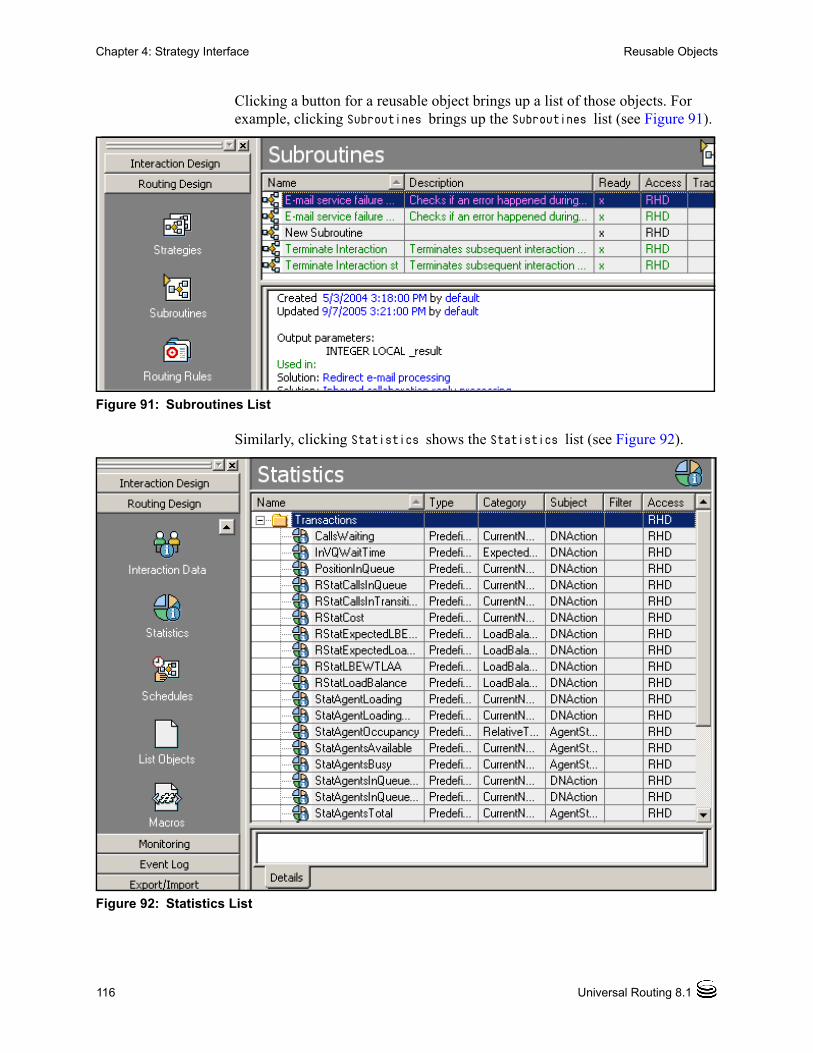
116 Universal Routing 8.1
Chapter 4: Strategy Interface Reusable Objects
Clicking a button for a reusable object brings up a list of those objects. For example, clicking Subroutines brings up the Subroutines list (see Figure 91).
Figure 91: Subroutines List
Similarly, clicking Statistics shows the Statistics list (see Figure 92).
Figure 92: Statistics List

Business Process—User’s Guide 117
Chapter 4: Strategy Interface Reusable Objects
Summary information about each reusable object is presented in the following section. The information includes whether the reusable object applies to non-voice interactions. Detailed information can be found in Universal Routing 8.1 Reference Manual and Interaction Routing Designer 8.1 Help.
Strategies
A strategy is a set of decisions and instructions that tell Universal Routing Server how to handle and where to direct interactions under different circumstances (see Figure 28 on page 44).
• You load a voice routing strategy in IRD Monitoring view by clicking the Monitoring shortcut (see Figure 90 on page 115) followed by the Loading or Group Loading shortcut (not shown). In the case of Loading view, you select the switch and routing point, right-click, select Load Strategy from the menu, and select a strategy from a dialog box.
• You load non-voice (multimedia) strategies on virtual routing points (see Figure 67 on page 84) by using the Strategy Activation Wizard (see Figure 322 on page 363).
Subroutines
A subroutine (previously called a substrategy) is a strategy called from within a strategy using the Call Strategy object (see Table 13 on page 209) or another subroutine. Like a strategy, a subroutine provides instructions to URS on how to route an interaction. A subroutine can contain any of the IRD objects, routing rules, or functions, including another subroutine.
• Subroutine names appear in the Subroutines list, instead of in the Strategies list. You get to this list by clicking the Subroutines icon that is shown in Figure 90 on page 115.
• When in IRD’s Interaction Design window, the object browser (see Figure 36 on page 61) lists any subroutines associated with strategies in a Subroutines folder.
For more information on subroutines, including the dialog boxes that are used for subroutine input and output parameters, see Universal Routing 8.1 Reference Manual. The “Business Process Samples” on page 369 include sample subroutines.
Routing Rules
Used only by voice routing strategies in 7.6, routing rules specify the method of target selection. Figure 93 shows an example routing rule.

118 Universal Routing 8.1
Chapter 4: Strategy Interface Reusable Objects
Figure 93: Example Routing Rule
Many voice Routing objects (see “Buttons for Routing Objects” on page 125) use routing rules in their properties. These include: Force, Load Balancing, Percentage. Service Level, Statistics, Switch to Strategy, and Workforce.
The Route Interaction object that is discussed on page 126 does not use routing rules. Other objects that do not use routing rules are the Default object and the Routing Selection object (see page 125).
Attributes
Used mostly by voice routing strategies, attributes are pieces of call or customer data and all possible values. In order to use each piece of data for strategy decisions, you must first define each piece of data in IRD as an attribute. You can then use the attributes to create business rules. Figure 94 shows some example attributes.

Business Process—User’s Guide 119
Chapter 4: Strategy Interface Reusable Objects
Figure 94: Example Attributes
Do not confuse attribute reusable objects that you define in IRD with Configuration Manager Business Attributes that are used by non-voice routing strategies (see page 161).
Business Rules
Used mostly by voice routing strategies, business rules are created from the attributes just discussed. Business rules and their attributes enable you to create logical expressions for segmentation. Figure 95 shows some example business rules.
Figure 95: Example Business Rules
The advantage of using them is that they allow you to reuse the same business decision multiple times in the same strategy and in many different strategies. See Universal Routing 8.1 Strategy Samples for more information.
Interaction Data
Used by both voice and non-voice routing strategies, interaction data defines attached data keys used in a strategy (see Figure 96).

120 Universal Routing 8.1
Chapter 4: Strategy Interface Reusable Objects
Figure 96: Example Interaction Attributes
You define interaction data in order to allow strategies to gather attached data. You can use interaction data in the following Miscellaneous objects discussed ahead (see page 126): Assign, If, and Function.
Statistics
You can define a custom statistic for use in within a strategy or subroutine. Or you can use or edit one of IRD’s predefined statistics (see Figure 92 on page 116). For more information, see the chapter on routing statistics in the Universal Routing 8.1 Reference Manual.
When creating routing strategies that will be called by business processes, there is one particular predefined statistic that business process designers may find useful: StatAgentLoadingMedia.
The StatAgentLoadingMedia statistic works like StatAgentLoading with one difference: StatAgentLoadingMedia returns data about the current media (not the whole agent). For example, assume Stat Server reports for some agent vector state:
• voice - one busy agent, one available agent
• e-mail - three busy agents, two available agents
In this case, StatAgentLoading will return four available agents.
StatAgentLoadingMedia, if executed for call with media type of voice, will return 1; if executed for call with media type of e-mail, will return 3.
For information about calculating the minimum or maximum value of this statistic, see the E-mail object description in Universal Routing 8.1 Routing Reference Manual.
Schedules
Used mostly for voice routing strategies, a schedule instructs Universal Routing Server when to load/release a specific voice routing strategy automatically, including the switch and DNs to use. You can specify times for loading and releasing schedules using seconds, minutes, hours, dates, months,

Business Process—User’s Guide 121
Chapter 4: Strategy Interface Reusable Objects
years, and days. After saving, the schedule definition is stored in Configuration Manager as a Script object of type Schedule. See the Universal Routing 8.1 Interaction Routing Designer Help for more information.
List Objects
Used mostly for voice routing strategies, a list object contains strings of any nature (for example, DNIS or ANI strings), which can be used in strategies and are included in integrity checking. Figure 97 shows an example.
Figure 97: Example List Object
May be used to create lists of toll-free numbers. Rather than reference each individual 800 number in a strategy, you can logically group numbers together and name the group. Then, when you need to add/edit numbers, the strategy does not need changing; you just add to/edit the list object. See the Universal Routing 8.1 Interaction Routing Designer Help for step-by-step instructions. For examples of list object use, see the chapter on Share Agent by Service Level Agreement Routing in the Universal Routing 8.0 Routing Application Configuration Guide.
Macros
A macro is a Miscellaneous object (see page 126) that allows you to combine several objects and expressions in one re-usable block. This block works as a user-defined function. IRD supplies the following predefined macros: Delimit TargetList, ComplexSample, MakeAgentNotReady, RedirectCall, RedirectCallMakeNotReady, and SimpleSample. For more information, see Universal Routing 8.1 Reference Manual.

122 Universal Routing 8.1
Chapter 4: Strategy Interface Strategy-Building Objects
Strategy-Building ObjectsBesides the reusable objects just discussed, IRD also provides strategy-building objects. Icons for each object category appear on the objects toolbar in the Routing Design window when you create or edit a strategy or subroutine. Figure 98 shows the Routing Design window with only the starting Entry object, which appears when you start a new strategy.
Figure 98: Routing Design Window with Entry Object
When you click an icon in the toolbar that represents an object category, buttons for all objects that belong to that category drop into view. For example, if you click the third icon (Segmentation) in Figure 98, buttons for all Segmentation objects drop into view (see Figure 99).
Figure 99: Dropdown Buttons for Segmentation Objects
Icons forobjectcategories
Segmentation Icon
Buttons forSegmentationObjects
Button forGeneric SegmentationObject

Business Process—User’s Guide 123
Chapter 4: Strategy Interface Routing Design Toolbar
Routing Design ToolbarFigure 100 shows the Routing Design window toolbar for each strategy-building object category.
Figure 100: Strategy Building Object Categories
Note: When you are working in the Routing Design window (see Figure 114 on page 132), the strategy-building objects toolbar is dockable. It can be removed from its current position and be placed anywhere within the Routing Design window.
Object Buttons Associated with Toolbar Icons
Clicking an icon on the toolbar drops down a button bar for placing objects in your strategy. The next section describes the object buttons associated with each object category. The object buttons are listed in toolbar order.
Buttons for Treatment Objects
Treatment objects apply to voice interactions. Figure 101 shows the buttons that come into view when you click the Treatments icon in Figure 100.
Figure 101: Buttons for Treatment Objects
Treatment objects specify an action that is to be performed with the current interaction, such as playing music for the caller.
The Treatment objects from left to right are the following: Collect digits, Play announcement, Play announcement and collect digits, Play application, Record user announcement, Verify digits, Busy, Fast busy, Cancel call, Delete user
TreatmentsDatabase
Segmentation Miscellaneous
Multimedia
Outbound SMS
Routing
Workflow and Resource Management

124 Universal Routing 8.1
Chapter 4: Strategy Interface Routing Design Toolbar
announcement, IVR, Music, Ringback, Set default destination, Silence, Text to speech, Text to speech and collect digits, Pause, RAN (Play recorded announcement). See the section on treatment objects in the Universal Routing 8.1 Reference Manual for more information.
Button for Data & Services
Figure 102 shows the buttons that come into view when you click the Data and Services icon in Figure 100 on page 123.
Figure 102: Buttons Under Data & Services
• Clicking the first button in Figure 102 and placing the object in your strategy opens the Database Wizard used for database lookups.
• The second button, External Service, enables you to exchange data with third party (non-Genesys) process servers that use the Genesys Interaction SDK or any other server/application that complies with Interaction Server communication protocol.
• The third button, Web Service, enables you to interact with Web-based applications outside of Genesys applications.
Note: For more information on the above strategy-building objects, as well as the strategy-building objects summarized in the pages ahead, see “IRD Objects Used in Business Processes” on page 201.
Buttons for Segmentation Objects
Clicking the third button on the objects toolbar in Figure 100 on page 123 reveals additional buttons for various types of Segmentation objects (see Figure 103).
Figure 103: Buttons for Segmentation Objects
Segmentation objects separate incoming interactions and put them on different paths based on criteria that you select. The buttons from left to right are the following:
• Generic (dialog box brings up Expression Builder that is shown in Figure 119 on page 136)

Business Process—User’s Guide 125
Chapter 4: Strategy Interface Routing Design Toolbar
• Date
• Time
• Day of the Week
• ANI (originating phone)
• DNIS (number dialed)
• Business
• Classify (Classification Switch)
• Screen
Note: The ANI and DNIS objects are intended for voice interactions. The Classify and Screen Segmentation objects are intended for multimedia interactions.
Buttons for Routing Objects
Clicking the fourth button on the objects toolbar (see Figure 100 on page 123) reveals additional buttons for various types of Routing objects (see Figure 104).
Figure 104: Buttons for Routing Objects
Routing objects specify a routing action that is to be performed with the current interaction, such as connecting a customer to a specific agent group. The buttons from left to right are the following:
• Service Level
• Load Balancing
• Percentage
• Statistics
• Switch to Strategy
• Default
• Force
• Selection
• Workforce
• Route Interaction
• Workbin
• Queue Interaction

126 Universal Routing 8.1
Chapter 4: Strategy Interface Routing Design Toolbar
Note: The Route Interaction, Queue Interaction, and Workbin objects are intended for routing strategies that are called by business processes. The remaining objects apply to voice routing strategies.
Buttons for Miscellaneous Objects
Clicking the fifth button on the objects toolbar (see Figure 100 on page 123) reveals additional buttons for various types of Miscellaneous operations (see Figure 105).
Figure 105: Buttons for Miscellaneous Objects
Miscellaneous objects are used for flow control or for performing operations, such as executing a function or directing interactions that are based on an If statement. The buttons from left to right are the following:
• Entry (IRD automatically places it as the first object in a strategy)
• Exit
• If
• Assign
• Function
• Macro
• Error Segmentation
• Call Subroutine
• Multi-Assign
• Multi-Attach
• Multi-Function
Buttons for Multimedia Objects
Clicking the sixth button on the objects toolbar (see Figure 100 on page 123) reveals additional buttons for Multimedia objects (see Figure 106).
Figure 106: Buttons for Multimedia Objects

Business Process—User’s Guide 127
Chapter 4: Strategy Interface Routing Design Toolbar
The buttons from left to right are the following:
• Stop Interaction
• Acknowledgement
• Autoresponse
• Chat Transcript
• Send E-mail
• Redirect E-mail
• Forward E-mail
• Reply from External Resource
• Screen
• Multi-Screen
• Classify
• Attach Categories
• Create Interaction
• Create E-mail Out
• Create Notification
• Create SMS
• Identify Contact
• Update Contact
• Render Message Content
• Find Interaction
• Update Interaction
• Update UCS Record
• Submit New Interaction
• Distribute Custom Event
See Table 8 on page 201 for summary information on these objects.
Buttons for Outbound Objects
Clicking the seventh button (Outbound) on the objects toolbar reveals additional buttons to support the Genesys Outbound product including proactive interaction routing (see Figure 107).
Figure 107: Buttons for Outbound Objects

128 Universal Routing 8.1
Chapter 4: Strategy Interface Routing Design Toolbar
The buttons from left to right are the following:
• Add Record
• Do Not Call
• Processed
• Update Record
• Reschedule Record
Note: The Outbound objects are designed to be used in strategies that are configured for proactive routing functionality, which are Open Media interactions that are processed with the outbound_preview media type. For more information, see the Genesys 7.6 Proactive Routing Solution Guide.
Buttons for Workflow and Resource Management Objects
Clicking the eighth button (Workflow and Resource Management) on the objects toolbar reveals additional strategy-building objects that enable you to control certain settings for strategies, Places, and Agents (see Figure 108).
Figure 108: Buttons for Workflow and Resource Management Objects
The buttons from left to right are the following:
• Set Multimedia Strategy State
• Set Agent DND State
• Set Agent Media State
• Force Logout
See Table 9 on page 206 for summary information on these objects.
Buttons for SMS Objects
Clicking the ninth button (SMS Objects) on the objects toolbar reveals buttons used for creating and sending SMS messages (see Figure 109).
Figure 109: Buttons for SMS Objects

Business Process—User’s Guide 129
Chapter 4: Strategy Interface Using the Strategy-Building Objects
The buttons from left to right are the following:
• Create SMS Out
• Send SMS Out
See Table 10 on page 207 for summary information on these objects.
Using the Strategy-Building ObjectsThis section explains how you define interaction processing in a strategy by using strategy-building objects.
Procedure:Placing an object in a strategy, configuring itsproperties, and connecting it to another object
Purpose: To define an interaction processing step within a strategy.
Start of procedure
Using the Generic Segmentation strategy-building object as an example:
1. Click the icon for Segmentation objects to drop down the button toolbar (see Figure 103 on page 124).
2. Click the button for the Generic Segmentation object on the toolbar (first button in Figure 99 on page 122).
3. Click inside the Routing Design window (see Figure 98 on page 122) to place the object inside the strategy.
4. Connect the Entry object to the Generic Segmentation object by connecting (drawing a line from) the bottom port of Entry object to the left input port of the Generic Segmentation object.
5. Double-click the Segmentation object in the Routing Design window to open its dialog box (see Figure 110).

130 Universal Routing 8.1
Chapter 4: Strategy Interface Using the Strategy-Building Objects
Figure 110: Generic Segmentation Properties Dialog Box: Starting
6. Assign properties in the dialog box. For this object, properties are expressions created in Expression Builder. To keep things simple, details on Expression Builder are not included here (but are included in “Segmenting Interactions” on page 328). Assume, after creating expressions, that the dialog box appears as shown in Figure 111.
Figure 111: Generic Segmentation Properties Dialog Box: Completed
7. Click OK to close the Generic Segmentation Properties dialog box.
End of procedure
New Entry Button
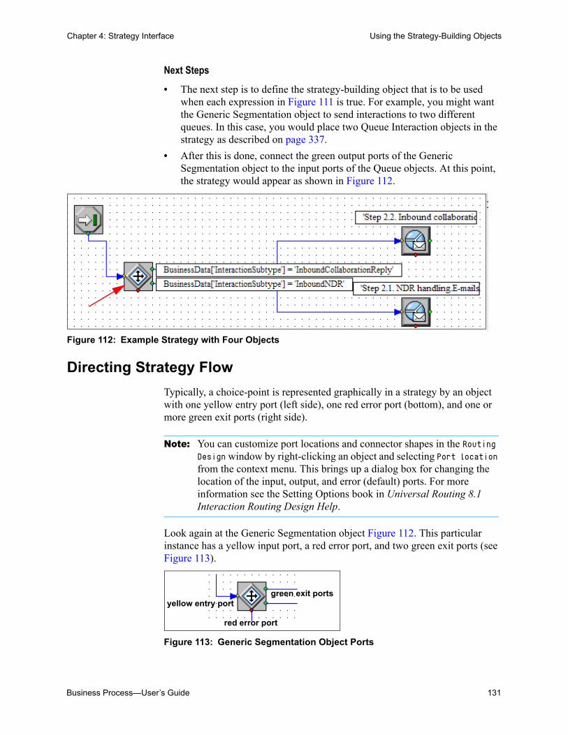
Business Process—User’s Guide 131
Chapter 4: Strategy Interface Using the Strategy-Building Objects
Next Steps
• The next step is to define the strategy-building object that is to be used when each expression in Figure 111 is true. For example, you might want the Generic Segmentation object to send interactions to two different queues. In this case, you would place two Queue Interaction objects in the strategy as described on page 337.
• After this is done, connect the green output ports of the Generic Segmentation object to the input ports of the Queue objects. At this point, the strategy would appear as shown in Figure 112.
Figure 112: Example Strategy with Four Objects
Directing Strategy Flow
Typically, a choice-point is represented graphically in a strategy by an object with one yellow entry port (left side), one red error port (bottom), and one or more green exit ports (right side).
Note: You can customize port locations and connector shapes in the Routing Design window by right-clicking an object and selecting Port location from the context menu. This brings up a dialog box for changing the location of the input, output, and error (default) ports. For more information see the Setting Options book in Universal Routing 8.1 Interaction Routing Design Help.
Look again at the Generic Segmentation object Figure 112. This particular instance has a yellow input port, a red error port, and two green exit ports (see Figure 113).
Figure 113: Generic Segmentation Object Ports
yellow entry port
red error port
green exit ports
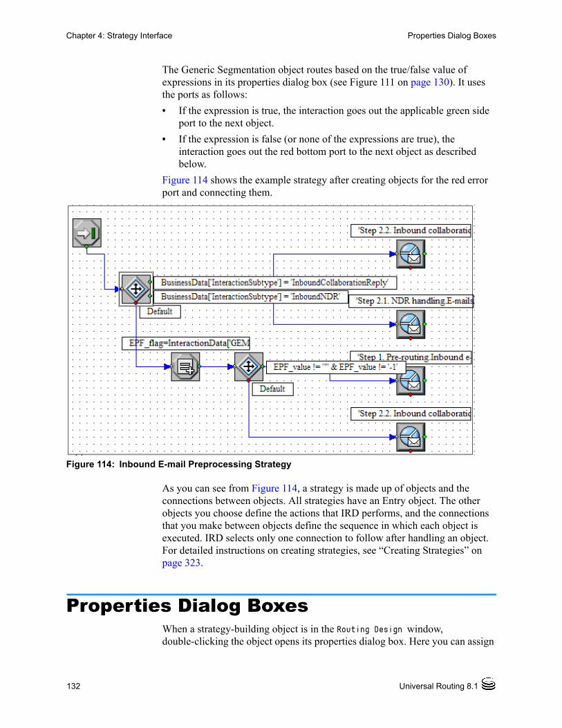
132 Universal Routing 8.1
Chapter 4: Strategy Interface Properties Dialog Boxes
The Generic Segmentation object routes based on the true/false value of expressions in its properties dialog box (see Figure 111 on page 130). It uses the ports as follows:
• If the expression is true, the interaction goes out the applicable green side port to the next object.
• If the expression is false (or none of the expressions are true), the interaction goes out the red bottom port to the next object as described below.
Figure 114 shows the example strategy after creating objects for the red error port and connecting them.
Figure 114: Inbound E-mail Preprocessing Strategy
As you can see from Figure 114, a strategy is made up of objects and the connections between objects. All strategies have an Entry object. The other objects you choose define the actions that IRD performs, and the connections that you make between objects define the sequence in which each object is executed. IRD selects only one connection to follow after handling an object. For detailed instructions on creating strategies, see “Creating Strategies” on page 323.
Properties Dialog BoxesWhen a strategy-building object is in the Routing Design window, double-clicking the object opens its properties dialog box. Here you can assign

Business Process—User’s Guide 133
Chapter 4: Strategy Interface Properties Dialog Boxes
values to the object’s parameters. The content of the properties dialog box varies based on the object. Different examples are presented below. Figure 115 shows an example completed properties dialog box for the Route Interaction object.
Figure 115: Example Route Interaction Properties Dialog Box
The selectable parameters in properties dialog boxes are object-specific. For example:
• When you use the Route Interaction object that is shown in Figure 115, the parameters in the Target Selection tab are the routing targets that are shown in the drop-down menu.
In contrast, when you use the Workbin routing object (see page 292), targets are limited to Agent, Agent Group, Variable, or Skill.
• The parameters of some Segmentation objects are logical expressions (see “Building Logical Expressions” on page 135). Figure 116 shows the Assign Properties dialog box in which the expression is assigned to a variable.
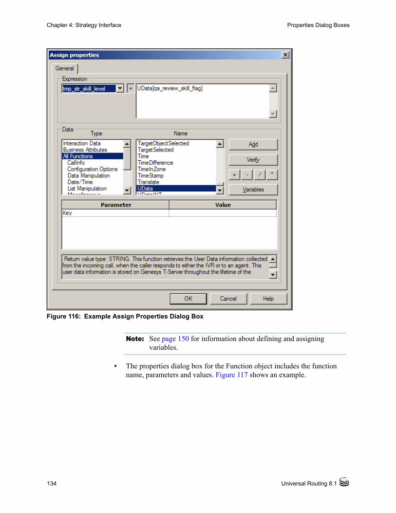
134 Universal Routing 8.1
Chapter 4: Strategy Interface Properties Dialog Boxes
Figure 116: Example Assign Properties Dialog Box
Note: See page 150 for information about defining and assigning variables.
• The properties dialog box for the Function object includes the function name, parameters and values. Figure 117 shows an example.

Business Process—User’s Guide 135
Chapter 4: Strategy Interface Building Logical Expressions
Figure 117: Example Function Properties Dialog Box
In summary, parameters entered in properties dialog boxes are object-specific and vary with each object.
Note: Almost every IRD object opens its own properties dialog box. The exceptions are: Entry, Exit, Default Route, and Treatment Cancel Call, and a few Function objects.
Building Logical ExpressionsThe properties of several IRD objects are defined as logical expressions. When creating a logical expression, you use Expression Builder.

136 Universal Routing 8.1
Chapter 4: Strategy Interface Building Logical Expressions
For example, if you are using the Generic Segmentation object, click the down arrow that appears when you click under Expression in the object’s properties dialog box (see Figure 118).
Figure 118: Generic Segmentation Object Down Arrow
Clicking the arrow that is shown in Figure 118 brings up the Expression Builder. Figure 119 shows the Expression Builder after construction of an expression.
Figure 119: Expression Builder Dialog Box
Miscellaneous Objects and Logical Expressions
Under the Miscellaneous icon (see Figure 105 on page 126), the If, Assign, and certain Function objects (see Figure 140 on page 152) all use logical

Business Process—User’s Guide 137
Chapter 4: Strategy Interface Building Logical Expressions
expressions. The area for constructing the expression in these objects is the same as Figure 119 on page 136. Figure 120 shows an example completed If Expression Properties dialog box.
Figure 120: If Expression Properties Dialog Box
When placed in a strategy, the true/false value of the expression causes interactions to take different paths.
• If the expression is true, the interaction goes out the applicable green port to one object.
• If the expression is false, the interaction goes out the applicable red port to another object.
Routing Objects and Logical Expressions.
Under the Routing icon (see Figure 104 on page 125), the target Selection and Route Interaction objects use logical expressions in the form of a skill

138 Universal Routing 8.1
Chapter 4: Strategy Interface Building Logical Expressions
expression. These two objects use the Skill Expressions dialog box, which opens when you select Skill as a target type and click the arrow under Name. Figure 121 shows an example Route Interaction Properties dialog box with a skill expression.
Figure 121: Skill Expression Properties Dialog Box
Functions for use in the Function object (see Figure 105 on page 126) that support skill expressions include CreateSkillGroup and Multiskill.
For more information on functions and creating valid expressions, see the Universal Routing 8.1 Reference Manual.

Business Process—User’s Guide 139
Chapter 4: Strategy Interface Comment Object
Comment ObjectUse a Comment object to annotate a strategy. You can insert a comment by right-clicking anywhere in the strategy and selecting Insert Comments (see Figure 122).
Figure 122: Insert Comments from Context Menu
A text box appears in the Routing Design window, which you can edit (see Figure 123).
Figure 123: Comments Text Box

140 Universal Routing 8.1
Chapter 4: Strategy Interface Other Design View Operations
Other Design View OperationsYou can perform other operations in the Routing Design window: close strategy, save strategy, backup, restore from previous version, cut, copy, paste, print, find, replace, and search. Use the toolbar that is shown in Figure 124.
Figure 124: Toolbar: Other Strategy Operations
Procedure:Searching for text strings
The Search button allows you to search for text strings used in a strategy including objects, rules, functions, and so on. You can only search one strategy at a time. Within a strategy, you can limit the search to multiple selected objects.
Start of procedure
1. Open the strategy from the Strategies list pane.
2. Click the Search button in the toolbar (see Figure 124). The Find dialog box opens.
3. Type the name of the object into the Find what field. This feature is case sensitive so type the name exactly as it appears in the strategy. If you only want to search for an exact match, select the Match whole word only option.
Assume you type empl_id. The Find dialog box appears as shown in Figure 125.
Close StrategySave Strategy
Restore From Previous VersionBackup
Cut Copy Paste PrintFind and Replace
Search
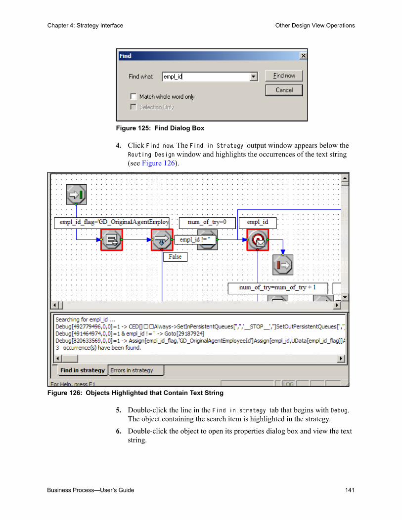
Business Process—User’s Guide 141
Chapter 4: Strategy Interface Other Design View Operations
Figure 125: Find Dialog Box
4. Click Find now. The Find in Strategy output window appears below the Routing Design window and highlights the occurrences of the text string (see Figure 126).
Figure 126: Objects Highlighted that Contain Text String
5. Double-click the line in the Find in strategy tab that begins with Debug. The object containing the search item is highlighted in the strategy.
6. Double-click the object to open its properties dialog box and view the text string.

142 Universal Routing 8.1
Chapter 4: Strategy Interface Routing Design Options
7. Move through the list of string occurrences that appear in the list by using the Enter or Arrow keys on your keypad or the F3 function key. The object that contains the text string is highlighted as you move through the list.
End of procedure
Routing Design OptionsThe annotations that are shown in Figure 126 on page 141 are not user-entered comments. The annotations appear in the Routing Design window when you select Routing Design Options from the Tools menu and set the Graph Settings tab as shown in Figure 127:
Figure 127: Graph Settings Tab
Note: The Routing Design Options dialog box applies to the Routing Design window (see Figure 98 on page 122). IRD does not use it for the Interaction Design window (see Figure 36 on page 61), which has its own options dialog box (see Figure 70 on page 86).
Use the Graph Settings tab to more clearly document interaction flow. For example, assume you wish to review the flow of Chat inbound strategy discussed in “ABC Simple Chat BP” on page 379.
When you do not check any options in the Graph Settings tab that is shown in the Routing Design Options dialog box (see Figure 127 above), only the
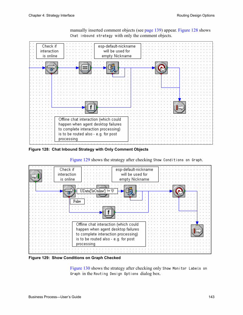
Business Process—User’s Guide 143
Chapter 4: Strategy Interface Routing Design Options
manually inserted comment objects (see page 139) appear. Figure 128 shows Chat inbound strategy with only the comment objects.
Figure 128: Chat Inbound Strategy with Only Comment Objects
Figure 129 shows the strategy after checking Show Conditions on Graph.
Figure 129: Show Conditions on Graph Checked
Figure 130 shows the strategy after checking only Show Monitor Labels on Graph in the Routing Design Options dialog box.
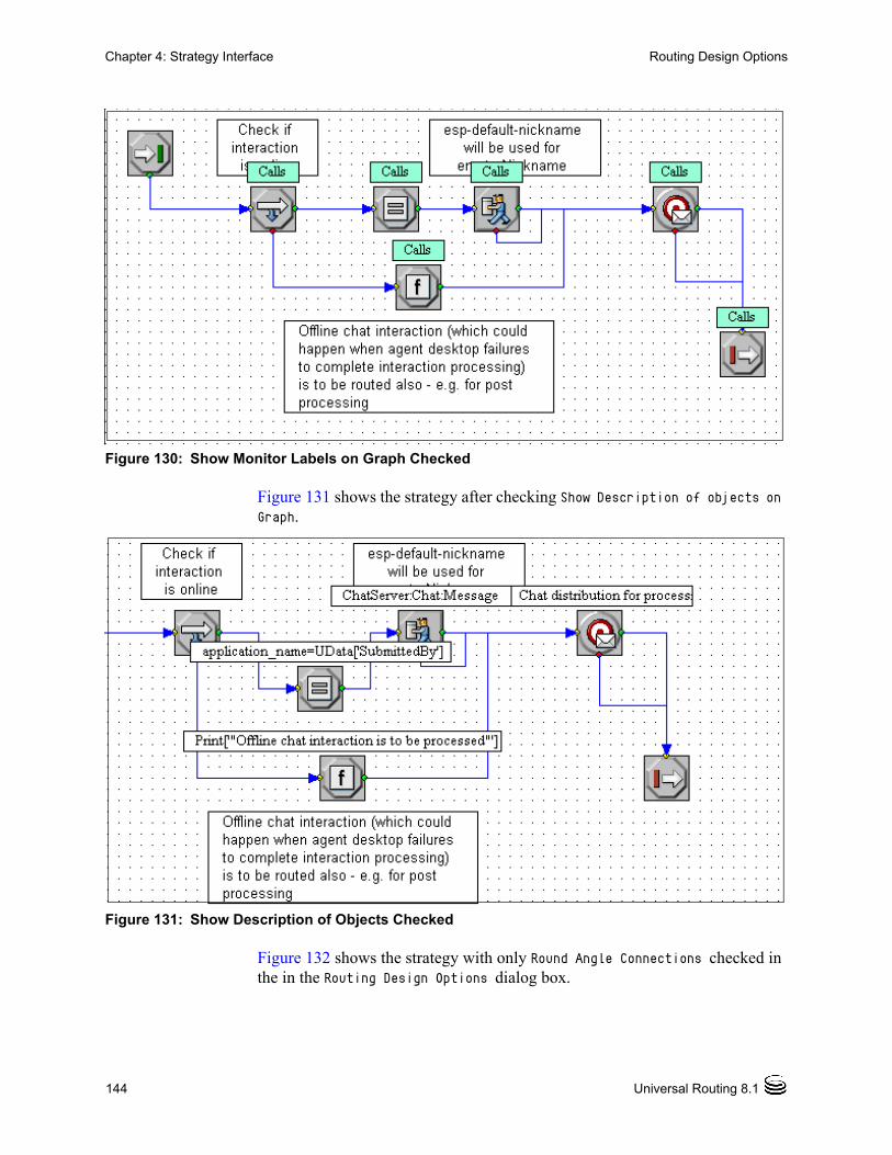
144 Universal Routing 8.1
Chapter 4: Strategy Interface Routing Design Options
Figure 130: Show Monitor Labels on Graph Checked
Figure 131 shows the strategy after checking Show Description of objects on Graph.
Figure 131: Show Description of Objects Checked
Figure 132 shows the strategy with only Round Angle Connections checked in the in the Routing Design Options dialog box.

Business Process—User’s Guide 145
Chapter 4: Strategy Interface Routing Design Options
Figure 132: Round Angle Connections Checked
This section now returns to the second tab in the Routing Design Options dialog box. Figure 133 shows the Storage Settings tab.
Figure 133: Storage Settings Tab

146 Universal Routing 8.1
Chapter 4: Strategy Interface Routing Design Options
Working directory
Keep the default or browse for a new one. This directory contains log and importstr folders. It can also contain the following files: import.log (after importing), export.log (after exporting), copyas.log (after save as), and save.log (after saving). Temporary strategy/subroutine files reside in the importstr subdirectory. See the Universal Routing 8.1 Interaction Routing Designer Help if you want more information on the temporary files in the importstr directory.
Autosave timer
Use to automatically save a currently active and open strategy or subroutine at the indicated interval while the strategy is being edited. If IRD shuts down or freezes, you can restore the last edited version of the strategy that was autosaved.
Compatible strategy saving mode
Normally you will leave unchecked (the default). Select only if you will you want to save a strategy created with IRD 7.6 in compatible mode so that it can be opened with an older version of IRD (prior to 7.5). When unchecked, IRD saves the strategy in a memory-efficient format.
Note: You can also specify a default storage location by Tenant. For details, see the Universal Routing 8.1 Interaction Routing Designer Help.
Use the Default Font tab to specify the strategy comments font (see Figure 134).
Figure 134: Default Font Tab

Business Process—User’s Guide 147
Chapter 4: Strategy Interface Database Wizard
Note: If you have a strategy currently open, you must close and re-open the strategy in order for the change to take effect.
Use the Views tab to specify the IRD GUI elements to display (see Figure 135).
Figure 135: Views Tab
Note: New settings take effect upon IRD application restart.
Database WizardDatabase-driven routing means that an interaction is routed based on information retrieved from a database. You can build a strategy that instructs URS to:
• Query a database for any information, including customer name and language, but also for account level, ID of the last agent who handled the customer, and so on.
• Attach this information to the interaction.
• Route the interaction to the appropriate agent.
You use the Database Wizard object (see Figure 102 on page 124) for this purpose. Figure 136 shows an example voice strategy that uses the Database Wizard object.

148 Universal Routing 8.1
Chapter 4: Strategy Interface Database Wizard
Figure 136: Example Database Lookup Strategy
This strategy routes based on the customer’s revenue potential (Customer Tier). Customers are ranked by importance based on their account number. Based on its three possible values (Platinum, Gold, and Silver), the interaction is routed to an agent with a corresponding skill range.
Figure 137 shows the Database Wizard dialog box that opens when you place the Database Wizard object in a strategy.

Business Process—User’s Guide 149
Chapter 4: Strategy Interface Database Wizard
Figure 137: Database Wizard Starting Dialog Box
Note: To see all the Database Wizard dialog boxes, refer to Universal Routing 8.0 Strategy Samples. Also see Universal Routing 8.1 Reference Manual.
Summaries of each Database Wizard dialog box are presented below.
• After click Next as shown in Figure 137, the next Database Wizard object dialog box retrieves from the table samplecustomer the value of the field Tier for the record where the field AccountNumber equals the number contained in the interaction.
• The next Database Wizard dialog box constructs the WHERE clause (see Figure 138).
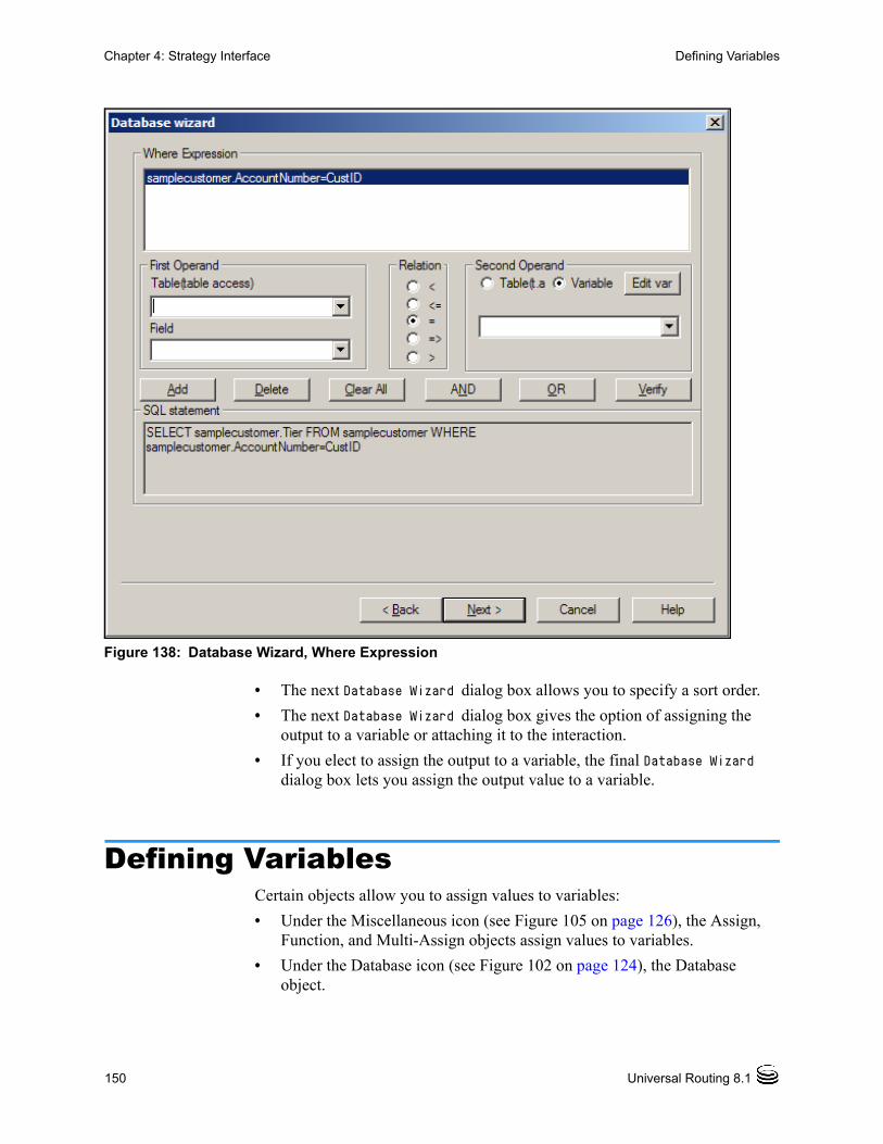
150 Universal Routing 8.1
Chapter 4: Strategy Interface Defining Variables
Figure 138: Database Wizard, Where Expression
• The next Database Wizard dialog box allows you to specify a sort order.
• The next Database Wizard dialog box gives the option of assigning the output to a variable or attaching it to the interaction.
• If you elect to assign the output to a variable, the final Database Wizard dialog box lets you assign the output value to a variable.
Defining VariablesCertain objects allow you to assign values to variables:
• Under the Miscellaneous icon (see Figure 105 on page 126), the Assign, Function, and Multi-Assign objects assign values to variables.
• Under the Database icon (see Figure 102 on page 124), the Database object.

Business Process—User’s Guide 151
Chapter 4: Strategy Interface Defining Variables
Variable List Dialog Box
Use the Variable List dialog box to define variables and to move definitions of variables used in one strategy to another strategy. Figure 139 shows the Variable List dialog box with several variables defined.
Figure 139: Variable List Dialog Box
Bring up the Variable List dialog box as follows:
• When working with a strategy, click the Variables button on the toolbar to bring up this dialog box.
• In the Database Wizard object (see Figure 137 on page 149), when you assign the output or key-value pairs to one or more variables, a dialog box opens. Here you click the Edit Variables button to bring up the Variable List dialog box.
• In the Generic Segmentation object, click the down arrow in the Expression column to bring up the Expression Builder (see Figure 119 on page 136). In the Expression Builder, click the Variables button.
• Under the Miscellaneous icon (see Figure 105 on page 126), in the properties dialog box for the If, Assign, or Function objects, click the Variables button to bring up the Variable List dialog box. The Multi-Assign object lets you assign multiple variables at once using its own dialog box.
Using the Function object as an example, Figure 140 on page 152, shows the output of the Rand function (described in Universal Routing 8.1 Reference Manual) assigned to the variable min_skill_level.

152 Universal Routing 8.1
Chapter 4: Strategy Interface IRD Security
Figure 140: Function Object Properties Dialog Box
For more information, see “Defining Variables” on page 341. Also see the section on variables in the Universal Routing 8.1 Reference Manual.
IRD SecurityStarting with 7.6, IRD implements an inactivity timeout, which is fully described in the Genesys 8.0 Security Deployment Guide. This feature requires re-authentication (logging in again) after a period of user inactivity. The default period of inactivity is 0 (zero) minutes. To change the default in the IRD Application object, configure a value for the inactivity-timeout option as described in the Universal Routing 8.1 Reference Manual.
Note: IRD interprets the absence of the inactivity-timeout option or the setting of its value to 0 (zero) as disabling the feature of application locking as a result of user inactivity.

Business Process—User’s Guide 153
Chapter 4: Strategy Interface IRD Security
Important Information
• Upon expiration of the value set for the inactivity-timeout option, all opened IRD windows are hidden (minimized). You are presented with a re-login dialog box that, for authentication purposes, asks only for a user password in order to resume the Application session. All other fields are grayed out since the connection of the IRD Application to Configuration Server remains active the entire time until re-login.
If you want to end the Application session by pressing Cancel button, on the re-login dialog box you will be warned that you are about to exit the Application. To exit the Application, press the Yes button on the Do you want to close the application? warning message. To return to the re-login dialog box, press the No button.
• If the administrator changes a user’s password in Configuration Manager at any time during an IRD session before that user is presented with the re-login dialog box, the previous password will be required in order to resume the suspended session.
• In a case where the user changes a password in IRD before the expiration of the value set for the inactivity-timeout option, then only a new password will be accepted in the re-login dialog box in order to continue working with the Application.
• The Interaction Design window (see Figure 36 on page 61) behaves differently than the Routing Design window in the case where you want to end the Application session while you have unsaved changes. Unlike Routing Design, when you press the Yes button in order to close the Application, Interaction Design provides a message giving the possibility to save modifications made to a business process prior exiting.
IRD Access Permissions
Make sure that the Person object (see Figure 144 on page 160) for each user that will access IRD is assigned the required Access Group for IRD. Starting with 7.6, the Environment and Tenant objects have an option that defines the access permissions for a new Person object. The default is for a new Person object to have no access permissions unless you specify assign them in the Security tab of the Person properties dialog box.
Configuration Manager displays a warning message if you attempt to save a new Person object without assigning an Access Group. Any user without an assigned Access Group can open IRD, but can only view the IRD GUI. For more information on configuring Application level security, see the Genesys 8.0 Security Deployment Guide.

154 Universal Routing 8.1
Chapter 4: Strategy Interface IRD Security
Summary
The intent of this chapter is simply to introduce the strategy creation interface. You will use it to create the routing strategies that are discussed in “Creating Strategies” on page 323.

Business Process—User’s Guide 155
Chapter
5 Configuration Layer InterfaceThis chapter describes the interface that is used to create Configuration Manager objects used in strategies. For step-by-step instructions on creating these objects, see “Creating Configuration Manager Objects” on page 237.
This chapter includes the following sections: About Configuration Manager, page 155 Environment Folder and Tenants, page 156 Resources Folder, page 158 Scripts Folder, page 159 Business Attributes, page 161 Workflow Object Names, page 171 Graphical Portion of a Strategy, page 172 Setting Permissions, page 173
About Configuration ManagerConfiguration Manager is the Genesys software application that enables you to manipulate your contact center's configuration data and set user permissions for solution functions and data. Configuration Manager is one of the three mandatory components of the Configuration Layer:
• Configuration Database, which stores all configuration data. DB Server—a Services Layer component—serves as an access point to the Configuration Database.
• Configuration Server, which:
Provides centralized access to the Configuration Database, based on permissions that you can set for any user to any configuration object.

156 Universal Routing 8.1
Chapter 5: Configuration Layer Interface Environment Folder and Tenants
Maintains the common logical integrity of configuration data and notifies applications of changes made to the data.
As an optional feature, provides support for a geographically distributed environment.
• Configuration Manager.
Note: For information about logging into Configuration Manager, see page 237
Required Objects
Assuming that you have objects required by Framework and Universal Routing already configured, additional objects that you might need to define in Configuration Manager include:
• Persons. In addition to an agent, at various points in a business process, you will want to route an interaction to a supervisor, manager, or QA member. Before you can select that target in a Strategy object, the target must first be defined as a Person object in Configuration Manager.
• Skills (for assignment to Person objects)
• Agent Groups (collections of Person objects)
• Places and Place Groups (desks)
• Business Attributes (see Figure 146 on page 162).
• Table Access (instructions that tie together formats, database access points, and tables when accessing information in a non-SQL database)
• Email Accounts (external e-mail addresses)
• Capacity Rules (see “Agent Capacity Rules” on page 164)
Environment Folder and TenantsFigure 141 shows an example Configuration Manager interface. The right pane shows the Environment folder; the left pane shows Tenants.
• Tenants are businesses whose customer interactions are enabled or enhanced through services offered by a third party, typically a telecommunications service provider.
• From a functional standpoint, each Tenant in a Multi-Tenant environment is a contact center (single or multi-site) completely equipped to process customer interactions.
The example in Figure 141 includes three Tenant objects (including Environment).

Business Process—User’s Guide 157
Chapter 5: Configuration Layer Interface Environment Folder and Tenants
Figure 141: Environment Folder Expanded
The object presentation in Configuration Manager depends on the type of Genesys configuration environment, which can be:
1. Enterprise (also referred to as Single-Tenant) or
2. Multi-Tenant.
Note: The type of Genesys configuration environment depends on the operation mode of Configuration Server. You set this mode by applying either Enterprise or Multi-Tenant installation scripts when you create the Configuration Database as described in the Framework 8.1 Deployment Guide.

158 Universal Routing 8.1
Chapter 5: Configuration Layer Interface Resources Folder
This guide assumes objects in the Environment folder—including Universal Routing Server (see page 49), E-mail Server (see page 51), and Interaction Server (see page 49) Applications —have already been configured.
Resources FolderFigure 142 shows folders for resources for a Tenant in a Multi-Tenant environment.
Figure 142: Resources Folder, Tenant Selected
Note: A Single-Tenant environment places resources in a folder called Resources.

Business Process—User’s Guide 159
Chapter 5: Configuration Layer Interface Scripts Folder
Scripts FolderWhen you create a new business process, Queue, View, or Strategy object, the associated Script file is stored in the Scripts folder in the Configuration Database (see Figure 143).
Figure 143: Scripts Folder
Warning! Do not use Configuration Manager to create these Script objects manually. To ensure internal integrity, use only IRD to create these objects.

160 Universal Routing 8.1
Chapter 5: Configuration Layer Interface Scripts Folder
Viewing Object Properties
To view an object’s properties, double-click its icon in the right pane. For example:
1. Expand the Persons folder to find a Person object.
2. Double-click a Person object in the right pane to open a properties dialog box (see Figure 144).
Figure 144: Agent Properties Dialog Box, General Tab

Business Process—User’s Guide 161
Chapter 5: Configuration Layer Interface Business Attributes
3. Click the Agent Info tab to see any Skills or Capacity Rules that are assigned to the agent (see Figure 145).
Figure 145: Agent Properties Dialog Box, Agent Info Tab
Business AttributesBusiness Attributes are interaction attributes that are used in different ways within Genesys. Figure 146 shows the content of the Business Attributes folder.
Note: See the Note on page page 72 about updating properties for View, Queue, and Workbin objects.

162 Universal Routing 8.1
Chapter 5: Configuration Layer Interface Business Attributes
Figure 146: Business Attributes Folder
When designing strategies for business processes, you can use the attributes in the Business Attributes folder (see as follows:
• The If object (see Figure 120 on page 137) and Assign object (see Figure 116 on page 134) give the option of selecting Business Attributes when constructing an expression.
• When using the Function or Multi-Function objects, certain functions use Business Attributes including Attach, Business Data, Update, and UpdateBusinessData.
• The Generic Segmentation object (see page 129) lets you select Business Attributes when constructing an expression.

Business Process—User’s Guide 163
Chapter 5: Configuration Layer Interface Business Attributes
Figure 147: Generic Segmentation Object Using Business Attributes
Note: In the above example, the function uses a Business Attribute called Customer Segment, which can be used to categorize a customer based on their revenue potential. For example, in the credit card business, customers are categorized according to their maximum spending limit. This is indicated by whether the customer has a Platinum (high), Gold (medium) or Bronze (low) credit card.
• The Multi-Attach Miscellaneous object (Table 8 on page 201) gives the option of attaching Business Attributes to interactions.
• The Forward and Redirect objects require you to select an E-mail Account.
• The Classify object requires you to select e-mail Categories.
• The Screen and Multi-Screen objects require you to select Screening Rules (see page 233).

164 Universal Routing 8.1
Chapter 5: Configuration Layer Interface Business Attributes
Media Type Business Attribute
A frequently used Business Attribute is Media Type. Figure 148 shows the Business Attributes and Media Type folders expanded.
Figure 148: Media Types in Business Attributes Folder
Agent Capacity Rules
Note the agent capacity rule that is assigned to the agent in Figure 145 on page 161. A capacity rule (which can be assigned at the Tenant (default), Person (agent), or Place level) defines an agent’s ability to handle simultaneous interactions of different media types.

Business Process—User’s Guide 165
Chapter 5: Configuration Layer Interface Business Attributes
URS is required to use agent capacity information when routing non-voice interactions such as those handled by business processes. After defining a complete set of available agents (taking agent capacity rules into consideration if configured), URS applies the routing selection criteria specified in the strategy objects.
Capacity rules reside in the Genesys Configuration Database as Script objects. By default, the Multimedia Wizard puts capacity rules in a Scripts folder under the Solutions folder for the Tenant.
Creating a New Capacity Rule
To create a new capacity rule in Configuration Manager, you must have the Resource Capacity Planning Wizard installed (available on the Real-Time Metric Engine CD). You can then right-click the Scripts folder and select Wizard > New > Capacity Rule from the context menu (see Figure 149).
Figure 149: Capacity Rule in Scripts Folder Under Solutions
This action brings up the Resource Capacity Planning Wizard (see Figure 150).
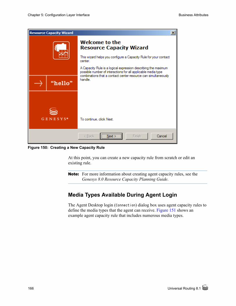
166 Universal Routing 8.1
Chapter 5: Configuration Layer Interface Business Attributes
Figure 150: Creating a New Capacity Rule
At this point, you can create a new capacity rule from scratch or edit an existing rule.
Note: For more information about creating agent capacity rules, see the Genesys 8.0 Resource Capacity Planning Guide.
Media Types Available During Agent Login
The Agent Desktop login (Connection) dialog box uses agent capacity rules to define the media types that the agent can receive. Figure 151 shows an example agent capacity rule that includes numerous media types.

Business Process—User’s Guide 167
Chapter 5: Configuration Layer Interface Business Attributes
Figure 151: Example Agent Capacity Rule
Assume that the capacity rule that is shown in Figure 151 is associated with an agent who is logging in (see Figure 145 on page 161). You can configure the Agent Desktop Connection dialog box to list:
• All of the media types that are shown in Figure 151.
• Only certain media types if you edit the multimedia option that is associated with the Agent Desktop Application object as described later.
Figure 152 shows the Connection dialog box with only a subset of media types shown.

168 Universal Routing 8.1
Chapter 5: Configuration Layer Interface Business Attributes
Figure 152: Dialog Box for Logging In
In order to receive interactions of a specific media type, the agent must check that media type in the Connection dialog box.
Figure 152 does not list all the media types shown in the capacity rule in Figure 151 on page 167. This is because you can limit the media types shown in the Connection dialog box via the media option in the ion Agent Desktop Application object.
Procedure:Limiting media types during login
Purpose: To limit the media types that an agent can check in the Connection dialog box to a subset of the media types associated with the capacity rule.
Start of procedure
1. Open Configuration Manager.
2. Select the Tenant if applicable.
3. Open the Applications folder.
controlled by mediaoption in multimediasection

Business Process—User’s Guide 169
Chapter 5: Configuration Layer Interface Business Attributes
4. Open the Agent Desktop Application object (see Figure 153).
Figure 153: Agent Desktop Application Object
5. Click the Options tab (see Figure 154).
Figure 154: Agent Desktop Application Object, Options Tab
6. Select the multimedia section and click the icon to edit the section/option (see Figure 155).
Figure 155: Icon to Edit Section/Option
7. In the resulting dialog box specify the media types to be shown in the login dialog box. Figure 156 shows an example completed dialog box that includes only some of the media types shown in Figure 152 on page 168.

170 Universal Routing 8.1
Chapter 5: Configuration Layer Interface Business Attributes
Figure 156: Edit Option Dialog Box
8. Click OK. The media types appear as option values (see Figure 157).
Figure 157: Media Option After Adding outboundpreview
End of procedure
Business Process—User’s Guide 171
Chapter 5: Configuration Layer Interface Workflow Object Names
Notes: To ensure proper handling of workflow post-processing features, you may also wish to set the following option in the Agent Desktop Application object, outbound section:
preview-park-queue
Values: __STOP__ (default), or any valid Interaction Queue name
For more information, see the section on handling Outbound and Callback interactions in the Genesys Desktop 7.6 Deployment Guide.
Workflow Object NamesIRD stores business process information as a set of objects in the Configuration Database where each object corresponds to a business process, queue, workbin, view, submitter or strategy. Each object is stored as type Script.
All Scripts in the Configuration Database share the same namespace. All Scripts must have unique names, which means a particular name can be used only once.
The Interaction Design window avoids this limitation by allowing business processes to be presented in a way where two different queues may have equally named views or two different business processes may have equally named queues or workbins.
This is accomplished by IRD using an auxiliary name (Namespace Relative, Figure 73 on page 89) for each Script object (which is also a Script object property). This allows you to reuse names across configurations with IRD controlling the uniqueness of the auxiliary names in their namespaces.
Note: IRD does not allow you to have equally named views that belong to the same queue, nor it does not allow having equally named queues that belongs to the same business process. The only object that must have a unique name in the whole configuration is a strategy/subroutine.
By default, IRD presents a business process in a way where only Namespace Relative names are displayed for queues, views and workbins. However, IRD can present a business process where each element shows its real name in the Configuration Database or even both. See page 88 for information about the Real Configuration Names, Namespace Relative, and Both options.
• The Namespace Relative option presents only auxiliary names.
• The Real Configuration Names option presents names of corresponding Script objects.
• The Both option shows both names. In this case, if an object has an auxiliary name different from its real name in the Configuration Database, the real name will be shown in brackets.

172 Universal Routing 8.1
Chapter 5: Configuration Layer Interface Graphical Portion of a Strategy
Graphical Portion of a StrategyThe script portion of a strategy and the graphical portion (.rbn file) may be stored in different locations. For example, while the script file is always stored in the Configuration Database, the graphical portion (which takes up more space) may be stored:
• In the Configuration Database in the ird_strategies table if an initialization script supplied by Genesys created the table.
• On a user’s local drive.
• On a network drive.
Note: If you do not have access to the .rbn file, you will not able to view a strategy in the Routing Design window.
To view the path pointing to the graphical portion of a strategy:
1. Double-click the strategy in the Scripts folder,
2. In the resulting properties dialog box, select the Annex tab. (If the tab does not appear, select View > Options from the Configuration Manager menu and select Show annex tab in object properties.)
3. Select the strategy section.
4. Double-click the path option (see Figure 158).
Figure 158: Strategy RBN File Path

Business Process—User’s Guide 173
Chapter 5: Configuration Layer Interface Setting Permissions
Business Attributes that Cannot Be Changed
Warning! Some Business Attributes should never be changed. See the chapter on interaction properties in the eServices (Multimedia) 8.0 User’s Guide for more information.
• For more examples of Business Attribute usage, see the section on e-mail routing strategies in Universal Routing 8.1 Strategy Samples.
• For information about creating Business Attributes, see page 243.
Setting PermissionsSet permissions by right-clicking an object in Configuration Manager, selecting Properties, clicking the Security tab and then the Permissions button to bring up a dialog box. You can then assign types of access to types of users. Figure 159 shows an example.
Figure 159: Example Object Permission Dialog Box for Agent Group
When you log into IRD, you are granted permissions for objects based on your group membership and object permissions. An Access tab appears in the list pane for each IRD object (see Figure 34 on page 59).

174 Universal Routing 8.1
Chapter 5: Configuration Layer Interface Setting Permissions
Table 4 describes the types of access.
Note: If you do not have access to the folder where the graphical portion of a strategy is stored, you will not able to view a strategy in the Routing Design window. For more information, see “Graphical Portion of a Strategy” on page 172.
Default of No Access for New Users
Starting with 7.6, the Environment and Tenant objects have an option that defines the access permissions for a new Person object created in Configuration Manager. The default is for a new Person object to have no access permissions unless you specify assign them in the Members of tab of the Person Properties dialog box. As a result, in order to use IRD 7.6, each Person object must have one or more Access Groups assigned. Any user does not have an assigned Access Group can open IRD, but can only view the IRD GUI. For more information, see the Genesys 8.0 Security Deployment Guide.
Summary
The intent of this chapter is simply to introduce the Configuration Manager interface. You will create Configuration Manager objects later in “Creating Configuration Manager Objects” on page 237.
Table 4: Access Control Types
Access control type
Appears in IRD List pane as (R=Read, H=Change, D=Delete)
No Access Object does not display
Read R
Change RHD
Full Access RHD
Special Access Depends on the selected option(s): Full Access: RHD; Read: R; Create: R; Change: RH; Execute: R; Delete: RD Read Permissions: R; Change Permissions: R; Read and Execute: R

Business Process—User’s Guide 175
Chapter
6 Knowledge Manager InterfaceThis chapter describes the interface used to create interaction classification Categories, Screening Rules, Standard Responses, as well as the Field Codes and Custom Variables that may be used in Standard Responses. For information about creating these objects, see “Creating Knowledge Manager Objects” on page 223.
This chapter includes these sections: About Knowledge Manager, page 175 Categories Tab, page 178 Field Codes Tab, page 183 Screening Tab, page 185 Training, Training Schedules, Models, and FAQ Tabs, page 188
About Knowledge ManagerAt some point in a business process, you may want to screen an interaction for certain words or word patterns, analyze an interactions content and assign Categories, or send a Standard Response. Before you can perform these functions in a strategy, you must define certain objects in Knowledge Manager (see Table 5 on page 176).

176 Universal Routing 8.1
Chapter 6: Knowledge Manager Interface About Knowledge Manager
After creating these objects in Knowledge Manager and saving the definitions in the Universal Contact Server Database, the object names carry over to the Configuration Database.
• The Knowledge Manager objects are then viewable in Configuration Manager (see Figure 148 on page 164 for an example).
• The Knowledge Manager objects are also selectable in the Strategy objects that use them (see Figure 365 on page 421 for an example).
Note: For information about logging into Knowledge Manager, see page 223.
Figure 160 shows an example Knowledge Manager with a Category expanded.
Table 5: Knowledge Manager Objects Used for Routing
Knowledge Manager Object
Routing Strategy Object That Uses:
Classification Categories
Classify object to automatically classify an interaction with a Category code based on its content (see Figure 162 on page 180). Once a Category code is assigned, other types of processing can occur based on the Category code, such as automatically generating a Standard Response.
Attach Categories object to manually attach classification Categories to an interaction (see Figure 163 on page 181).
Classification Segmentation object (see Figure 164 on page 181) to cause interactions to take different paths in the strategy based on an assigned classification Category.
Multi-Screen object to return Categories associated with Screening rules.
Standard Responses (which may include Field Codes and Custom Variables)
Acknowledgement, Autoresponse, Chat Transcript, Forward E-mail, Redirect E-mail, Create E-mail Out, Create Notification, and Create SMS objects.
Screening Rules Screen and Multi-Screen objects for screening interactions for certain words or word patterns. Once a Screening Rule match occur, you can configure other types of processing to occur.
Note: The primary difference between screening and classification is that the result of screening is a Screening Rule name and the value of true or false; the result of classification (you must have the Content Analyzer option installed) is a Category Code, which can be associated with a Standard Response or used for other purposes such as segmentation. For more information, see the chapter on IRD objects in the Universal Routing 8.1 Reference Manual.

Business Process—User’s Guide 177
Chapter 6: Knowledge Manager Interface About Knowledge Manager
Figure 160: Knowledge Manager Panes
The Knowledge Manager interface contains the following tabs.
• Categories
• Field Codes
• Screening
• Training
• Training Schedule
• Models
• FAQ
Note: The first three tabs are relevant to all users of Knowledge Manager while the remaining tabs are relevant only to users of Genesys Content Analyzer if that option is installed (see page 50).
Table 6 summarizes each tab.
Category tree pane Standard Responses pane
Subcategories pane

178 Universal Routing 8.1
Chapter 6: Knowledge Manager Interface Categories Tab
Categories TabNote: For more information on Categories than presented here, see the
eServices (Multimedia) 8.0 User’s Guide.
Refer back to Figure 160 on page 177 to view the Categories tab with folders expanded.
Category Codes and Standard Responses
Category trees are integral to the classification functionality of Genesys Content Analyzer.
• Category trees are a means of organizing and gaining access to the library of Standard Responses. Each Standard Response must be associated with one category. One Category can have zero or many Standard Responses associated with it.
• Content Analyzer can classify an incoming e-mail in terms of the Category tree.
Table 6: Knowledge Manager Tabs
Relevance Tab Description
General Categories tab Displays and gives access to Category trees and their associated Standard Responses. Provides access to the Standard Response Editor.
Field Codes tab Displays the set of Field Codes and provides access to the Field Code Editor.
Screening tab Displays the set of Screening rules and provides access to the Screening Rules Editor.
Genesys Content Analyzer only
Training tab Displays the set of training objects and provides access to the Mail Editor.
Training Schedule tab
Displays start time, status, and other information about training objects.
Models tab Displays information about models.
FAQ tab A FAQ object takes Standard Responses and recasts them as answers to frequently asked questions.

Business Process—User’s Guide 179
Chapter 6: Knowledge Manager Interface Categories Tab
You use Knowledge Manager to create Category trees and to create and edit the associated Standard Responses, as well as the Field Codes that Standard Responses can contain.
Once Categories are defined in Knowledge Manager and saved in the Universal Contact Server Database, the object names carry over to the Configuration Database and are viewable in Configuration Manager (see Figure 161 and compare it to Figure 160 on page 177).
Figure 161: Classification Category Codes
Once the Categories are contained in the Configuration Database, the codes are viewable in various IRD object properties dialog boxes.
Category Codes in Classify Object and Attach Categories Objects
The IRD Classify object properties box displays classification Categories that were originally defined in Knowledge Manager (see Figure 162).

180 Universal Routing 8.1
Chapter 6: Knowledge Manager Interface Categories Tab
Figure 162: Classification Categories in Classify Object
IRD’s Attach Categories object is similar to the Classify object, but you use it to manually (instead of automatically) attach classification Categories to an interaction. Once this is done, one possible use would be to create a strategy where an If object creates an expression based on the attached Categories. You could then have interactions take different paths in the strategy based on those Categories.
Figure 163 shows an example completed Attach Categories Properties dialog box with Categories selected that were originally defined in Knowledge Manager.
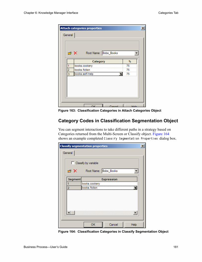
Business Process—User’s Guide 181
Chapter 6: Knowledge Manager Interface Categories Tab
Figure 163: Classification Categories in Attach Categories Object
Category Codes in Classification Segmentation Object
You can segment interactions to take different paths in a strategy based on Categories returned from the Multi-Screen or Classify object. Figure 164 shows an example completed Classify Segmentation Properties dialog box.
Figure 164: Classification Categories in Classify Segmentation Object

182 Universal Routing 8.1
Chapter 6: Knowledge Manager Interface Categories Tab
Category Codes in Acknowledgement and Autoresponse Objects
The Acknowledgement and Autoresponse objects allow you to select Standard Responses, which are previously defined in Knowledge Manager. Figure 165 shows an example Acknowledgement receipt properties dialog box where Standard Responses are selected.
Figure 165: Acknowledgement Object With Standard Response

Business Process—User’s Guide 183
Chapter 6: Knowledge Manager Interface Field Codes Tab
Field Codes TabNote: For more information than presented here, see the section on Field
Codes in the eServices (Multimedia) 8.0 User’s Guide.
Figure 166 shows the Knowledge Manager Field Codes tab.
Figure 166: Knowledge Manager Field Codes Tab
The main use of Field Codes is to particularize Standard Responses. Figure 167 shows a Standard Response that uses the Field Codes Contact.Title and Contact.FullName.
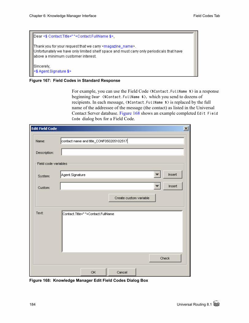
184 Universal Routing 8.1
Chapter 6: Knowledge Manager Interface Field Codes Tab
Figure 167: Field Codes in Standard Response
For example, you can use the Field Code <$Contact.FullName $> in a response beginning Dear <$Contact.FullName $>, which you send to dozens of recipients. In each message, <$Contact.FullName $> is replaced by the full name of the addressee of the message (the contact) as listed in the Universal Contact Server database. Figure 168 shows an example completed Edit Field Code dialog box for a Field Code.
Figure 168: Knowledge Manager Edit Field Codes Dialog Box
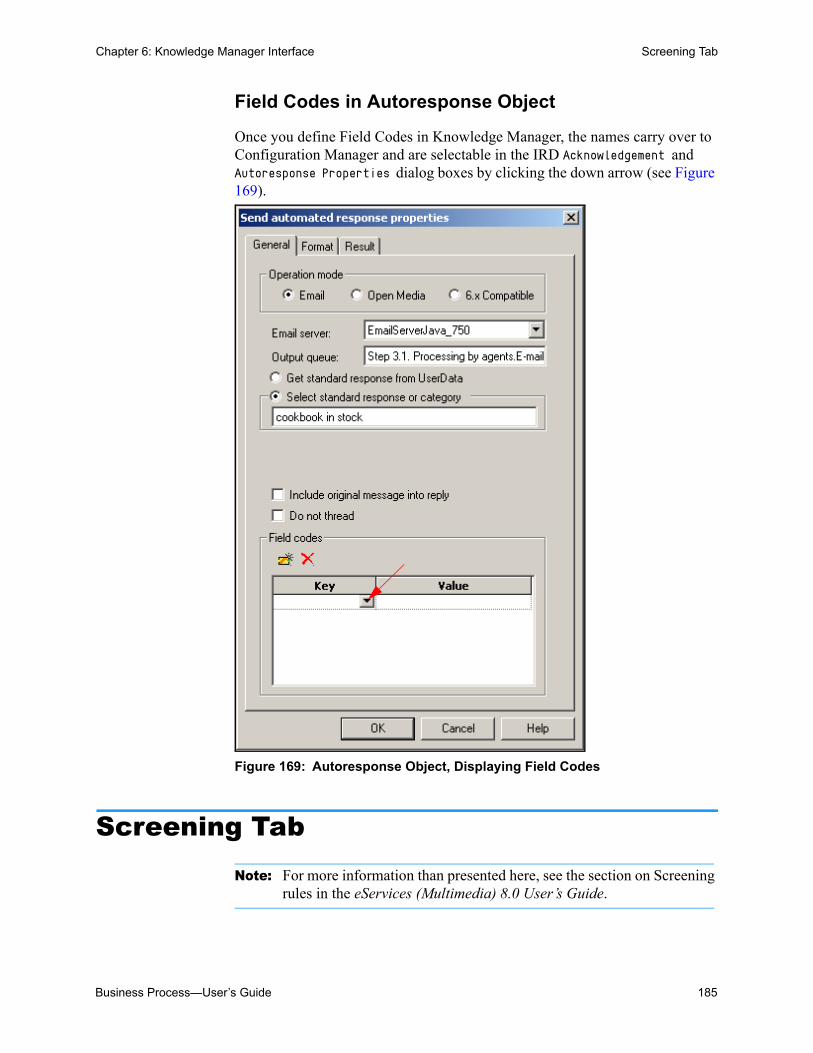
Business Process—User’s Guide 185
Chapter 6: Knowledge Manager Interface Screening Tab
Field Codes in Autoresponse Object
Once you define Field Codes in Knowledge Manager, the names carry over to Configuration Manager and are selectable in the IRD Acknowledgement and Autoresponse Properties dialog boxes by clicking the down arrow (see Figure 169).
Figure 169: Autoresponse Object, Displaying Field Codes
Screening TabNote: For more information than presented here, see the section on Screening
rules in the eServices (Multimedia) 8.0 User’s Guide.

186 Universal Routing 8.1
Chapter 6: Knowledge Manager Interface Screening Tab
Figure 170 shows the Knowledge Manager Screening tab with example entries.
Figure 170: Knowledge Manager Screening Tab
When triggered by a Screen object in a routing strategy, Classification Server uses Screening Rules to scan an interaction and try to match either an originating address, a regular expression, or both. Figure 171 shows an example completed Edit Screening Rule dialog box.

Business Process—User’s Guide 187
Chapter 6: Knowledge Manager Interface Screening Tab
Figure 171: Knowledge Manager Screening Tab

188 Universal Routing 8.1
Chapter 6: Knowledge Manager Interface Training, Training Schedules, Models, and FAQ Tabs
Note that a Screening Rule is associated with a Category and a Category is associated with a Standard Response (see Figure 160 on page 177). Once you define Screening Rules in Knowledge Manager, they carry over to the Genesys Configuration Database and become selectable in the IRD Screen object (see Figure 172).
Figure 172: Screen Object Showing Available Screening Rules
After an interaction is screened, you can use the Screen Segmentation object to have interactions take different paths in a strategy based on screening results (see Figure 375 on page 431).
Training, Training Schedules, Models, and FAQ Tabs
The last four tabs are relevant only to users of Genesys Content Analyzer and are not shown. For details, see eServices (Multimedia) 8.0 Knowledge Manager Help.

Business Process—User’s Guide 189
Chapter 6: Knowledge Manager Interface Training, Training Schedules, Models, and FAQ Tabs
Summary
The intent of this chapter is simply to introduce the Knowledge Manager interface. You will use Knowledge Manager later as described in “Creating Knowledge Manager Objects” on page 223.

190 Universal Routing 8.1
Chapter 6: Knowledge Manager Interface Training, Training Schedules, Models, and FAQ Tabs

Business Process—User’s Guide 191
Part
3 Creating a Business ProcessPart Three of this Universal Routing 8.1 Business Process User’s Guide provides information that you will need to create a business process, including information for the planning and preparation stage.
The information in Part Three is divided into the following chapters:
• Chapter 7, “Planning a Business Process” on page 195.
• Chapter 8, “Creating Knowledge Manager Objects” on page 223.
• Chapter 9, “Creating Configuration Manager Objects” on page 237.
• Chapter 10, “Creating Business Process Objects” on page 247.
• Chapter 11, “Creating Strategies” on page 323.
• Chapter 12, “Using a Business Process” on page 361.
Summary of Entire ProcessThis section summarizes the entire process of creating a business process. It includes the planning stage and creating the objects that must exist prior to creating the business process in IRD’s Interaction Design window.
Table 7 summarizes the steps that are required.

192 Universal Routing 8.1
Part 3: Creating a Business Process Summary of Entire Process
Table 7: High Level Steps to Create/Load a Business Process
Objective Related sections and procedures
1. Determine the interaction life cycle at your contact center.
Review a simple interaction life cycle: See “Basic Interaction Life Cycle” on page 195.
Review a more complex interaction life cycle: See “Using the Samples” on page 197.
2. Determine the IRD objects to be used in strategies to perform the various processing required at each stage of interaction processing.
Review the functionality associated with IRD objects commonly used in business processes. See “IRD Objects Used in Business Processes” on page 201.
3. For each interaction processing stage, assign a name to the required business processes.
Use the supplied worksheet in the section “Naming the Required Business Processes” on page 212.
4. Name the queues that will connect the strategies contained within each business process and/or connect one business process to another business process.
Use the supplied worksheet in the section “Naming the Required Queues” on page 213 to name the required queues.
5. Determine the selection criteria for extracting interactions from queues.
See “Determining View Criteria” on page 215.
6. Name the views that will extract interactions from queues.
Use the supplied worksheet in the section “View Information Worksheet” on page 216.
7. Review limitations. See “Configuration Manager Limitations” on page 219 and “IRD Limitations” on page 219.
8. Create Knowledge Manager objects, such as Categories, Standard Responses, Field Codes, and Screening Rules.
To create some of the objects that will be used in IRD objects contained in strategies, see “Creating Knowledge Manager Objects” on page 223.
Procedures:
• “Creating a New Category” on page 227.
• “Creating a Standard Response” on page 229.
• “Creating a Field Code” on page 231.
• “Creating a Screening Rule” on page 234.

Business Process—User’s Guide 193
Part 3: Creating a Business Process Summary of Entire Process
9. Create Configuration Manager objects, such as Skills, Persons, Agent Groups, Places, Place Groups, and Business Attributes.
To create some of the objects that will be used in IRD objects contained in strategies, see “Creating Configuration Manager Objects” on page 237.
Procedures:
• “Defining Skill objects that can be assigned to agents” on page 239.
• “Defining Person objects” on page 241.
• “Defining Agent Groups, Places, and Place Groups” on page 243.
• “Defining Business Attributes” on page 243.
10.Create the business process “container” that will contain the queues, strategies, views and other objects that perform interaction processing.
Use the following procedures:
• “Defining a Business Process Script object” on page 248
• “Adding endpoints” on page 254
• “Adding a Queue object” on page 258
• “Adding a View to a Queue object” on page 268
• “Completing the View object Condition tab” on page 272
• “Completing the View object Order tab” on page 274
• “Completing the Parameterized Conditions tab” on page 282
• “Adding a Workbin object to a business process” on page 293
• “Creating strategy placeholders” on page 300
• “Creating a Submitter object” on page 304
11.Create routing strategies for use inside business processes.
See “Creating Strategies” on page 323 for a list of procedures.
12.Activate the strategies inside business processes.
See “Activating Strategies” on page 361.
Table 7: High Level Steps to Create/Load a Business Process (Continued)
Objective Related sections and procedures

194 Universal Routing 8.1
Part 3: Creating a Business Process Summary of Entire Process
Business Process—User’s Guide 195
Chapter
7 Planning a Business ProcessThis chapter provides instructions for planning a business process. It covers the following topics: Basic Interaction Life Cycle, page 195 Using the Samples, page 197 Defining the Required Functionality, page 200 IRD Objects Used in Business Processes, page 201 Naming the Required Business Processes, page 212 Naming the Required Queues, page 213 Determining View Criteria, page 215 View Information Worksheet, page 216 Order of Configuration, page 217 Limitations, page 219
Basic Interaction Life CycleWhen you are planning a business process, start by considering the basic stages in interaction life-cycle processing. You can then design a business process that encompasses all stages, just one stage, or multiple stages. This section presents four basic stages in interaction life-cycle processing, which are especially applicable to e-mail processing. The stages are the following:
1. Pre-Route
2. Route-to-Agent
3. Review
4. Pre-Send
Each stage is summarized below.

196 Universal Routing 8.1
Chapter 7: Planning a Business Process Basic Interaction Life Cycle
Pre-Routing Stage
The main activities in the pre-routing stage can include, but are not limited to:
• Determining whether an interaction has already been processed by Genesys. This can be accomplished via the absence or presence of an Interaction Subtype (see “Step 1. Pre-Routing” on page 391).
• If Content Analyzer is installed, sending interactions to Classification Server for assignment of one or more Category codes previously defined in Knowledge Manager (see Figure 162 on page 180). Once a Category code is assigned to an interaction, you can configure other types of processing to occur based on the Category code.
• Screening interactions for certain words or patterns of words (see “Step 2.3. New Inbound E-mails” on page 396). Once a Screening Rule match occurs, you can configure other types of processing based on the true/false value.
• Sending an acknowledgement and/or automatic Standard Response to the customer originating the interaction (see “Step 2.3. New Inbound E-mails” on page 396).
• Determining the agent that previously handled the interaction (see “Step 2.1. NDR Handling” on page 393).
Route-to-Target Stage
This may or may not be an agent target. For example, the interaction may be:
• Sent to a queue for submittal to other routing strategies and further processing (see “Step 2.3. New Inbound E-mails” on page 396).
• Sent to a queue for failed interactions (see “Step 2.2. Inbound Collaboration Reply” on page 394).
• Forwarded outside the contact center to an expert with the expectation of getting a response back (see “Step 3.3. Forwarding” on page 403).
• Redirected to another agent without the expectation of getting a response back (see “Step 3.4. Redirecting” on page 405).
• Routed to an agent target for construction of a response (see “Step 3.1. Processing By Agents” on page 399).
Review Stage
The reviewer could be a manager, supervisor, or QA Person (see “Defining Persons” on page 241). You may want to have two different types of quality-assurance review:
1. A supervisor review that checks the skills of the agent who constructed the response (see “Step 3.2. QA Review” on page 401).

Business Process—User’s Guide 197
Chapter 7: Planning a Business Process Using the Samples
2. An analysis that performs a “sanity check;” for example, to prevent sending out a bank account password in an interaction or to screen interactions for inappropriate language.
Pre-Send Stage
The cycle of going from queue to routing strategy to queue can continue until the interaction reaches some final outbound queue (see “Step 4. Outbound Sending” on page 407). The pre-send stage performs last-minute quality checking and allows for attaching additional information to interactions when needed.Another approach to defining the interaction life cycle is to study the Genesys-supplied business process samples.
Using the SamplesWhen you install the Genesys Multimedia software, you have the option of installing a component called Interaction Workflow Samples (see Figure 173).
Figure 173: Interaction Workflow Samples

198 Universal Routing 8.1
Chapter 7: Planning a Business Process Using the Samples
The Workflow Samples component (samples) includes various business processes and associated queues, views, submitters, workbins, and routing strategies. The samples show how interaction processing can be contained in one large business process or broken down into smaller business processes connected with queues.
Samples Functionality
Note: For a description of each sample, see “Business Process Samples” on page 369.
The Default BP business process shown in Figure 173 demonstrates “real world” workflow complexity. In order to help you understand Default BP, a group of samples isolate its functional areas. For each functional area of Default BP, such as pre-routing, the samples supply a corresponding step-numbered business process (see Figure 173 on page 197). For example, Figure 174 shows the pre-routing area in Default BP. +
Figure 174: Pre-routing Area in Default BP
The pre-routing area in Default BP in Figure 174 corresponds to the Step 1. Pre-routing business process shown in Figure 175 on page 199.

Business Process—User’s Guide 199
Chapter 7: Planning a Business Process Using the Samples
Figure 175: Step 1. Pre-Routing Business Process
Connecting Business Processes Via Queues
As can be seen in Figure 175, Step 1. Pre-routing directly outputs to four queues:
1. Collaboration reply e-mails. Input queue for Step 2.2. Inbound Collaboration Reply.
2. E-mails to route to original agent. Input queue for Step 2.1. NDR Handling.
3. Inbound e-mail failure.
4. Inbound e-mail postprocessing. Input queue for Step 2.3. New Inbound E-mails.

200 Universal Routing 8.1
Chapter 7: Planning a Business Process Defining the Required Functionality
Queues can connect business processes in this manner to create an interaction workflow. You can find the business process that “owns” (originated) a queue by right-clicking the queue and selecting Locate from the menu. The queue is highlighted in the object browser under the business process that owns the queue. If the queue originated in a different business process, it displays an up arrow (see Figure 9 on page 28).
Step-Numbered Business Processes
The step-numbered business processes demonstrate how to construct the functional areas of Default BP. To help you estimate the queues and strategies you will need if you wish to emulate the samples, Table 30 on page 389 shows the elements in each step-numbered business process. It also points you to the corresponding IRD objects used to implement the functional area.
Defining the Required FunctionalityTo isolate the interaction processing functionality that is required at your contact center, you can start by using the samples to these questions:
1. What functionality from the first column in Table 30 on page 389 is applicable to your site? The middle column in Table 30 on page 389 shows the IRD objects you could use. The third column shows the queues you would need to define if emulating the samples.
2. Is there any special interaction processing functionality that is required at your contact center that is not covered by the first column in Table 30 on page 389 or by the overall samples functionality (see “Samples Functionality” on page 371).
3. Can the Web Service (see Table 14 on page 210) or External Service object (see Table 8 on page 201) be used to supply this functionality?
4. Does this special interaction functionality require its own business process or will it be part of another business process?
5. What queues and strategies are required to implement this special functionality?
6. What are your contact center’s special conditions for extracting interactions from queues? See “Interaction Attributes” on page 216.
After listing the interaction processing functionality that is required at your site, decide whether you should:
• Create one large business process as demonstrated by Default BP (see page 387).
• Build a number of smaller business processes and connect them via queues as demonstrated by the step-numbered samples (see page 389).
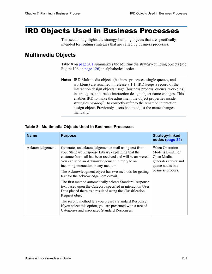
Business Process—User’s Guide 201
Chapter 7: Planning a Business Process IRD Objects Used in Business Processes
IRD Objects Used in Business ProcessesThis section highlights the strategy-building objects that are specifically intended for routing strategies that are called by business processes.
Multimedia Objects
Table 8 on page 201 summarizes the Multimedia strategy-building objects (see Figure 106 on page 126) in alphabetical order.
Note: IRD Multimedia objects (business processes, single queues, and workbins) are renamed in release 8.1.1. IRD keeps a record of the interaction design objects usage (business process, queues, workbins) in strategies, and tracks interaction design object name changes. This enables IRD to make the adjustment the object properties inside strategies on-the-fly to correctly refer to the renamed interaction design object. Previously, users had to adjust the name changes manually.
Table 8: Multimedia Objects Used in Business Processes
Name Purpose Strategy-linked nodes (page 34)
Acknowledgement Generates an acknowledgement e-mail using text from your Standard Response Library explaining that the customer’s e-mail has been received and will be answered. You can send an Acknowledgement in reply to an incoming interaction in any medium.
The Acknowledgment object has two methods for getting text for the acknowledgement e-mail.
The first method automatically selects Standard Response text based upon the Category specified in interaction User Data placed there as a result of using the Classification Request object.
The second method lets you preset a Standard Response. If you select this option, you are presented with a tree of Categories and associated Standard Responses.
When Operation Mode is E-mail or Open Media, generates server and queue nodes in a business process.

202 Universal Routing 8.1
Chapter 7: Planning a Business Process IRD Objects Used in Business Processes
Attach Categories Lets you manually emulate the results of the Classify object’s request to Classification Server to attach one or more classification Categories to an interaction.
Use when creating a strategy in which screening results determine what Categories to attach to an interaction with the Attach Categories object.
Use when creating a strategy in which an If object creates an expression based on Categories manually attached to interaction with Attach Categories object. URS analysis (true/false) of the expression determines interaction path in strategy.
You can also segment interactions based on Categories using the Classify Segmentation object and/or use Categories to select a Standard Response.
Autoresponse Generates (but does not send) an automatic response message using text from your Standard Response Library. You can send an Autoresponse in reply to an incoming interaction in any medium.
The Autoresponse object has two methods for getting a Standard Response.
1. The first method automatically selects a Standard Response based upon the Category specified in interaction User Data placed there as a result of using the Classification Request object.
2. The second method lets you preset a Standard Response. If you select this option, you are presented with a tree of Categories and associated Standard Responses.
When Operation Mode is E-mail or Open Media, generates server and queue nodes in a business process.
Chat Transcript Generates (but does not send) an e-mail, using text from your Standard Response Library, with the customer's chat transcript attached. (Use the Send E-Mail object to send it.) Does not generate any strategy-linked nodes in a business process.
Generates server and queue nodes in a business process.
Table 8: Multimedia Objects Used in Business Processes (Continued)
Name Purpose Strategy-linked nodes (page 34)

Business Process—User’s Guide 203
Chapter 7: Planning a Business Process IRD Objects Used in Business Processes
Classify (note: there is also a Classify Segmentation object)
Requests Classification Server to assign one or more Categories to text-based interactions. The Categories can then be used to select a Standard Response, as well as for routing or reporting.
The input parameters include the minimum relevancy each Category must have in order for Classification Server to consider an interaction as belonging to that Category (threshold). Parameters also specify whether to analyze only for the Parent Categories set up in Configuration Manger or both parent and child Categories.
Create E-mail Out Creates an outbound e-mail interaction. This outbound e-mail is sent via an E-mail Server that has been specifically configured to handle Open Media interactions.
Use the Send E-Mail object to send this message after it has been created.
Generates server and queue nodes in a business process.
Create Interaction Has URS request that an interaction record be created in the Universal Contact Server database for a customer contact. This object applies to all interaction types other than voice, chat, or e-mail. The UCS Database can store three types of interaction content simultaneously: Text, Structured Text, and Binary Data. When interaction content is expected to be large, Genesys recommends using the Create Interaction object as early as possible in a strategy.
Create Notification Creates an informational e-mail to a customer. The e-mail may contain the information that is requested by the customer or may direct the customer to a URS on which the information is located.
The outbound e-mail is sent via an E-mail Server that has been specifically configured to handle Open Media interactions.
Generates server and queue nodes in a business process.
Create SMS Use to create a new outbound message in a format that is to be sent by a specifically configured E-mail Server to SMS-ready targets, such as cell phones, via an E-mail to SMS gateway.
Use the Send E-Mail object to send the SMS message after you have created it.
Generates server and queue nodes in a business process.
Distribute Custom Event
Delivers special events to reporting clients.
Table 8: Multimedia Objects Used in Business Processes (Continued)
Name Purpose Strategy-linked nodes (page 34)

204 Universal Routing 8.1
Chapter 7: Planning a Business Process IRD Objects Used in Business Processes
Find Interaction Queries Interaction Server for all or a number of interactions that correspond to specific conditions and listed in a specific order.
Forward E-mail Use when sending an incoming message to an external address (see E-mail Accounts on page 246) with the expectation of getting a response back. Supports agent collaboration. The resource can be another agent such as an “expert” or an e-mail server. The Forward E-Mail object is a request to E-mail Server for method Forward to create the forwarded e-mail. Use the Send E-Mail object to send the forwarded e-mail that is waiting in a queue.
Generates server and queue nodes in a business process.
Identify Contact Use to locate one or more contacts in the Universal Contact Server (UCS) database with attributes that match data attached to the interaction. If you choose to match one unique contact, if UCS locates it, it returns all stored data concerning that contact.You can also choose to have UCS create a new contact if no existing contact matches the attached data.This object requires you to specify a Contact Server.
MultiScreen See Screen object. The difference between the two objects is that MultiScreen can use multiple Screening Rules, supplies additional return options, and does not require a conditional test to determine whether a match occurred.
Redirect E-mail Used when sending an incoming message to an external address (see E-mail Accounts on page 246) without expecting a response or the need for any further processing. The Redirect E-Mail object is a request to E-mail Server for method Redirect to create the redirected e-mail. Use the Send E-Mail object to send the redirected e-mail that is waiting in a queue.
Generates server and queue nodes in a business process.
Reply from External Resource
Takes an External Resource Reply inbound e-mail as input (such as one generated as a result of using the Forward object), extracts the external resource reply text from it, creates a Customer Reply outbound e-mail, and submits the e-mail to Interaction Server.
Generates server and queue nodes in a business process.
Render Message Content
Creates message content by using text from either a message box of the strategy object, strategy variable, User Data or Standard Response.
Table 8: Multimedia Objects Used in Business Processes (Continued)
Name Purpose Strategy-linked nodes (page 34)

Business Process—User’s Guide 205
Chapter 7: Planning a Business Process IRD Objects Used in Business Processes
Screen Requests Classification Server to screen text-based interactions for certain words or patterns of words using rules set up in Knowledge Manager.
You can choose to return Screening Rule identifiers (associated with Categories in Knowledge Manager) or Categories (associated with Standard Responses in Knowledge Manager), matched pairs, or all of the above.
Requires that you name the Classification Server used for screening as well as a language and a Screening Rule.
Send E-mail Sends an e-mail that is waiting in an interaction queue to a customer or another agent. This can be the final e-mail response or an e-mail generated with the Acknowledgement, Autoresponse, ChatTranscript, Forward, or Redirect object.
Stop Interaction Sends a stop interaction request to Interaction Server. Optionally, notifies Universal Contact Server that interaction processing in this particular routing strategy is finished. Requires a Reason Code.
Generates a stop node in a business process.
Submit New Interaction
Creates a new interaction in Interaction Server.
Update Contact Updates information for an existing contact in the Universal Contact Server (UCS) Database based on data associated with the interaction.
Update Interaction Updates properties of the interaction in the Interaction Server database that are not currently processed in the strategy by URS.
Update UCS Record Updates properties of the interaction in the Universal Contact Server database that are not currently processed in the strategy by URS.
Routing objects Certain Routing objects also generate queue, person, and stop nodes. See Table 11 on page 207 for more information.
Table 8: Multimedia Objects Used in Business Processes (Continued)
Name Purpose Strategy-linked nodes (page 34)

206 Universal Routing 8.1
Chapter 7: Planning a Business Process IRD Objects Used in Business Processes
Workforce and Resource Management
Table 9 describes Workforce and Resource Management objects (see Figure 108 on page 128) that can be used in strategies that are called by business processes.
Table 9: Workforce and Resource Management Objects Used in Business Processes
Name Purpose
Force Logout Use the Force Logout object to log out a Place or an Agent from all media that are controlled by Interaction Server. When this is done, the reported agent state (agent capacity vector) will not contain any media that are supported by Interaction Server.
Set Agent DND State
Use the Set Agent DND State object to turn the Agent DND status on or off. If this is set to off, all of the agent’s media that are controlled by Interaction Server will be reported as not accepting any interactions. If it is set to on, reported media status will be based on agent capacity rules.
Set Agent Media State
Use the Set Agent Media State object to change the state of the specified media to which the agent is logged on (if it is controlled by Interaction Server). If the media are set to Not Ready, it will be reported as not accepting any interactions. If the media are set to Ready, the status of the media will be reported based on agent capacity rules.
Set Multimedia Strategy State
Use the Set Multimedia Strategy State object as an additional method for managing workflows. Strategies can by activated or deactivated by an interaction that has specific properties.

Business Process—User’s Guide 207
Chapter 7: Planning a Business Process IRD Objects Used in Business Processes
SMS
Table 10 describes Workforce and Resource Management objects (see Figure 109 on page 128) that can be used in strategies that are called by business processes.
Routing Objects
Table 11 describes Routing objects (see Figure 104 on page 125) that can be used in strategies that are called by business processes.
Table 10: SMS Objects Used in Business Processes
Name Purpose Strategy-linked nodes (page 34)
Create SMS Out
Use the Create SMS Out object to instruct SMS Server to create a new SMS interaction that will be handled by using ESP technology.
Note: Do not confuse this object with the Create SMS object on the Multimedia toolbar. The Multimedia Create SMS object creates a specially-configured e-mail-type message that is sent by the E-Mail Server. The Create SMS Out object uses ESP technology to create an SMS message that is sent by SMS Server.
Generates a queue node in a business process.
Send SMS Out
Use the Send SMS Out object to send an SMS message that is created by using the Create SMS Out object.
Table 11: Routing Objects Used in Business Processes
Name Purpose Strategy-linked nodes
Route Interaction Routes a non-voice interaction to a specified target type: Agent, AgentGroup, Place, PlaceGroup, Skill (see Figure 121 on page 138)—or to a target that is contained in a variable (see “Defining Variables” on page 150).
Generates a queue node in a business process. If Agent is specified as a target, generates a person node in a business process.

208 Universal Routing 8.1
Chapter 7: Planning a Business Process IRD Objects Used in Business Processes
The remaining Routing objects on the toolbar are intended for voice routing strategies.
Segmentation Objects
Table 12 describes the Segmentation strategy-building objects that you will frequently use in routing strategies that are called by business processes.
Miscellaneous Objects
Any of the objects accessed from the Miscellaneous icon (see Figure 100 on page 123) can be used in routing strategies that are called by business
Workbin Use to place an interaction in a temporary storage area that is called a Workbin, which is associated with one of the following: Agent, AgentGroup, Place, or PlaceGroup
Generates a workbin node in a business process. If a Person object (agent) is specified as a target, generates a person node. If the Stop Processing(__ queue is selected, generates a stop node.
Queue Interaction Generates a message from URS to Interaction Server to place the interaction into a queue see page 47). Queues that are defined in the Interaction Design window (see page 258) are listed for selection.
Generates a queue node in a business process.
Table 11: Routing Objects Used in Business Processes (Continued)
Name Purpose Strategy-linked nodes
Table 12: Segmentation Objects Used in Business Processes
Name Purpose
Generic Segments interactions to take different paths in the strategy based on the true/false value of an expression created in Expression Builder (see Figure 119 on page 136). Expressions can be created using Interaction Data (see page 119), Business Attributes (see page 161), or Functions (see page 331). For an example, see “Segmenting Interactions” on page 328.
Screen Segments interactions to take different paths in the strategy (see Figure 364 on page 420) based on analyzing whether a Screening Rule match occurred.
Classify Segments based on classification Categories (see Figure 164 on page 181).

Business Process—User’s Guide 209
Chapter 7: Planning a Business Process IRD Objects Used in Business Processes
processes. However, if you study the samples, as described in “Business Process Samples” on page 369, you will note frequent use of the Miscellaneous objects listed in Table 13.
Note: For detailed information about using these and other strategy-building objects, see the section on IRD objects the Universal Routing 8.1 Reference Manual.
Data & Services
Table 14 describes Data & Services objects (see Figure 102 on page 124) that can be used in strategies that are called by business processes.
Table 13: Miscellaneous Objects Used in Business Processes
Name Purpose
Assign and Multi-Assign The Assign object (see Figure 116 on page 134) gives a value to a variable, which has been predefined in the Variable List dialog box (see Figure 139 on page 151). For an example, see page 341. The variable can then be used as a parameter of almost any object. For example, the Function object allows you to assign the function return to a variable.
Function When you open the properties dialog box for the Function object, you select one of the functions detailed in Universal Routing 8.1 Reference Manual. If applicable, you can use the Expression box (see Figure 140 on page 152) in the Function object to create an expression, which assigns the output to a variable.
If The properties dialog box lets you create an If expression (see Figure 120 on page 137). You can create expressions using Interaction Data (see page 119), Business Attributes (see page 161), or Functions (see page 331).
Error Segmentation The Error Segmentation object processes error codes generated by functions and objects. Connecting an object to the Error Segmentation object overrides standard behavior for a particular error. This enables further processing of errors and presents interactions from going to the default destination.
Call Subroutine The Call Subroutine object lets you all a subroutine from within a strategy or subroutine. When URS encounters this object in a strategy, control of the interaction is passed to the subroutine. Values can be passed between a strategy and a subroutine through input and output parameters

210 Universal Routing 8.1
Chapter 7: Planning a Business Process IRD Objects Used in Business Processes
Outbound
Note: The Outbound objects are designed to be used in strategies that are configured for proactive routing functionality, which are Open Media interactions that are processed with the outbound_preview media type.
Any of the objects that is accessed from the Outbound toolbar (see Figure 100 on page 123) can be used in routing strategies that are called by business processes. For more information about these objects and example strategies, see the Genesys 7.6 Proactive Routing Solution Guide.
Table 14: Data & Services Objects Used in Business Processes
Name Purpose
External Service Use to exchange data with third party (non-Genesys) servers that use the Genesys Interaction SDK or any other server or application that complies with Genesys Interaction Server (GIS) communication protocol.
Note: To use this object, you must already have created the third-party server or application in Configuration Manager. Before completing the object properties dialog box, you must already know the names of the services, methods, and signatures (requested input/output parameters) provided by the external service.
Web Service Use to interact with Web-based applications (Web Services) outside of Genesys applications. You specify request parameters, what type of data that you expect to be returned, and what to do with the returned data. This object can be used in both voice and non-voice routing strategies.

Business Process—User’s Guide 211
Chapter 7: Planning a Business Process IRD Objects Used in Business Processes
Table 15: Outbound Objects
Name Purpose
Add Record Use the Add Record object to automate building of Calling Lists by adding a new record to a specified Outbound List, such as a Calling List. For example, use to develop a Calling List, such as one to follow up on inbound calls that were abandoned during traffic peaks. You can then configure a routing strategy to detect abandoned calls and add records to the Calling List with the parameters of the incoming interactions. The Calling List can subsequently be used by an Outbound Campaign that dials out these customers during off peak hours and has the agent apologize and follow up.
Do Not Call Use to add a phone number or e-mail address to a specified Do Not Call List and mark the corresponding record as Do Not Call.
Use the Do Not Call and Processed (page 92) objects to finalize Outbound record processing. You cannot use other Outbound objects to process records with the same Record Handle after using Processed or DoNotCall in a strategy flow.
The Do Not Call object prevents a record from being dialed by any Campaign. If a record is marked as Do Not Call, Outbound Contact Manager rejects all subsequent requests for the record.
When URS executes this object in a strategy, it sends (via Interaction Server) a DoNotCall request to OCS. Using the GSW_RECORD_HANDLE provided, OCS:
• Identifies the record and updates the record type as NoCall.
• Enters the phone number and e-mail address or customer ID of this record in the gsw_donotcall_list (table).
If you require more information about Do Not Call Lists in general, see the section on submitting Do Not Call requests in the Outbound Contact 8.0 Reference Manual.
Processed Use to finalize Outbound record processing. You cannot use other Outbound objects to process records with the same Record Handle after using Processed or DoNotCall in a strategy flow.
In the Outbound Contact 7.6 product, when an agent finishes processing a Calling List record, Genesys Desktop sends a RecordProcessed event to indicate that the record is processed and Outbound Contact Server updates the record accordingly.
Use the Processed object in a strategy to have URS request that Outbound Contact Server finish processing a record created as a result of a customer call that was previously:
• Initiated from a Calling List
• Automatically dialed by the Genesys Outbound Contact product
• Routed to an agent when the potential customer answered
When URS executes this object in a strategy, it results in an External Service Request to Outbound Contact Server.
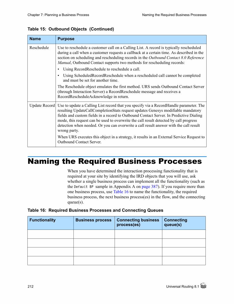
212 Universal Routing 8.1
Chapter 7: Planning a Business Process Naming the Required Business Processes
Naming the Required Business ProcessesWhen you have determined the interaction processing functionality that is required at your site by identifying the IRD objects that you will use, ask whether a single business process can implement all the functionality (such as the Default BP sample in Appendix A on page 387). If you require more than one business process, use Table 16 to name the functionality, the required business process, the next business process(es) in the flow, and the connecting queue(s).
Reschedule Use to reschedule a customer call on a Calling List. A record is typically rescheduled during a call when a customer requests a callback at a certain time. As described in the section on scheduling and rescheduling records in the Outbound Contact 8.0 Reference Manual, Outbound Contact supports two methods for rescheduling records:
• Using RecordReschedule to reschedule a call.
• Using ScheduledRecordReschedule when a rescheduled call cannot be completed and must be set for another time.
The Reschedule object emulates the first method. URS sends Outbound Contact Server (through Interaction Server) a RecordReschedule message and receives a RecordRescheduleAcknowledge in return.
Update Record Use to update a Calling List record that you specify via a RecordHandle parameter. The resulting UpdateCallCompletionStats request updates Genesys modifiable mandatory fields and custom fields in a record to Outbound Contact Server. In Predictive Dialing mode, this request can be used to overwrite the call result detected by call progress detection when needed. Or you can overwrite a call result answer with the call result wrong party.
When URS executes this object in a strategy, it results in an External Service Request to Outbound Contact Server.
Table 15: Outbound Objects (Continued)
Name Purpose
Table 16: Required Business Processes and Connecting Queues
Functionality Business process Connecting business process(es)
Connecting queue(s)

Business Process—User’s Guide 213
Chapter 7: Planning a Business Process Naming the Required Queues
Naming the Required QueuesMany of the Multimedia objects that are listed in Table 8 on page 201, as well as the Routing objects listed that are in Table 11 on page 207, require you to specify an output queue. Table 17 lists the objects that require output queues and contains columns for your queue names.
Table 16: Required Business Processes and Connecting Queues (Continued)
Functionality Business process Connecting business process(es)
Connecting queue(s)

214 Universal Routing 8.1
Chapter 7: Planning a Business Process Naming the Required Queues
Table 17: IRD Objects and Required Queues
IRD objects specifying queues
How queue is used Name of your queue
Originating business process
Acknowledgement Output queue in which E-mail Server should place the acknowledgement e-mail that will be sent to the customer.
Autoresponse Output queue in which E-mail Server should place the autoresponse e-mail that will be sent to the customer.
Chat Transcript Output queue in which E-mail Server should place the e-mail with the attached chat transcript that will be sent to the customer.
Create E-mail Out Output queue in which E-mail Server will find the e-mail.
Create Notification Output queue in which E-mail Server will find the e-mail.
Create SMS Interaction queue in which E-mail Server will find the messages.
Create SMS Out Output queue for outbound SMS.
Forward E-mail Output queue in which E-mail Server should place the e-mail that is to be forwarded.
Queue Interaction Output queue for the e-mail. Could be one read by agents, a queue for failed interactions, used for routing interactions from one business process to another, and so on.
Redirect E-mail Output queue in which E-mail Server should place the e-mail that is to be redirected.
Reply from External Resource
Output queue for outbound e-mails that contain final replies that are to be sent to customers.

Business Process—User’s Guide 215
Chapter 7: Planning a Business Process Determining View Criteria
Note: IRD predefines a Stop_processing (_STOP_) queue, which is not actually a queue, but a notification to Interaction Server that processing has stopped for a particular interaction if it reaches this point. For more information on this topic, see “IRD Limitations” on page 219.
Determining View CriteriaViews (see Figure 10 on page 28) extract interactions from queues or workbins. Part of the planning process includes determining whether all interactions should be extracted or a subset of interactions based selection criteria (see “Adding a View” on page 267).
You enter the selection criteria in the View properties dialog box (see Figure 221 on page 270). It has two tabs, Condition (see Figure 222 on page 273) and Order (see Figure 224 on page 274), where you specify column names and values (interaction attributes).
Route Interaction The Interaction Queue tab is optional. It gives the option of specifying:
A queue for the existing interaction. For example, after the agent constructs a response, the interaction might need to be checked by QA.
A queue for a new interaction if a new interaction is created.
Workbin The Interaction Queue tab is optional. It gives the option of specifying:
A queue for the existing interaction. For example, after the agent constructs a response, the interaction might need to be checked by QA.
A queue for a new interaction if a new interaction is created.
See “Adding Workbins” on page 292.
Table 17: IRD Objects and Required Queues (Continued)
IRD objects specifying queues
How queue is used Name of your queue
Originating business process

216 Universal Routing 8.1
Chapter 7: Planning a Business Process View Information Worksheet
Interaction Attributes
When you are creating a View object, you can create an expression that comprises:
• An interaction attribute (field) name from the interactions table
• An equal sign if required
• For string data, the attribute value in single quotes (not necessary for integers)
For an example, see Figure 222 on page 273.
Note: See the eServices (Multimedia) 8.0 User’s Guide for details on the interactions table, including column names and descriptions.
Some attribute values will be contained in the original e-mail. E-mail Server may assign other values. Routing strategy objects, such as the Database object or Classify object, may assign yet other values.
The attributes that you use to create the expression will be those in the interactions table as well as any custom attributes that you define in the interactions table (see custom_1s through custom_3n).
Translations
Translations, when they are used in the Conditions tab (see Figure 222 on page 273), provide database manipulation tools that are independent of the underlying database—including functions, attributes, and customizable property names for use in view and snapshot definitions.
Translations are optional. Interaction Server will accept either customized property names or actual database field and construct names. For more information, see the chapter on Interaction Properties in the eServices (Multimedia) 8.0 User’s Guide.
View Information WorksheetUse Table 18 to record view information.
Table 18: View Objects Configuration Data
View name Associated queue or workbin
Conditions (if any) Order by information (if any)
Business Process—User’s Guide 217
Chapter 7: Planning a Business Process Order of Configuration
Order of ConfigurationCertain objects must be defined in Knowledge Manager in order to be viewable in Configuration Manager. Similarly, certain objects must exist in the Configuration Database before the objects are selectable in IRD Strategy objects. Because of this dependency, Genesys recommends that you configure objects in the following order:
1. Start with Knowledge Manager (see “Knowledge Manager Interface” on page 175).
Table 18: View Objects Configuration Data (Continued)
View name Associated queue or workbin
Conditions (if any) Order by information (if any)

218 Universal Routing 8.1
Chapter 7: Planning a Business Process Order of Configuration
Define any required classification Categories, Standard Responses, Screening Rules, Field Codes, and Custom Variables (see “Creating Knowledge Manager Objects” on page 223).
Once these are saved in the Universal Contact Server Database, the object definitions carry over to Configuration Database and are accessible to the strategy-building objects that use them.
2. Next, use Configuration Manager (see “Configuration Layer Interface” on page 155).
Define any required media server, Skill, Person, Agent Group, Place, Place Group, and certain Business Attribute objects (see “Creating Configuration Manager Objects” on page 237).
Once these are saved in the Configuration Database, the objects are selectable in the IRD objects that use them.
3. If not already defined, use the Interaction Design window to define endpoints (see Figure 24 on page 40) for the media server Application objects.
4. Use the Interaction Design window (see Figure 36 on page 61) to define Business Process objects, including queues, views, and strategy placeholders (see “Creating Business Process Objects” on page 247).
Once definitions are saved in the Configuration Database, the names are selectable in the strategy-building objects that use them.
Notes: The properties dialog box for most of the IRD Multimedia objects requires an interaction output queue. Before any interaction queue can be listed for selection in one of the Multimedia objects, you must first associate the queue with a business process in the Interaction Design window.
The properties dialog box for the Workbin object requires you to select a workbin name. In order for a workbin name to display for selection in the Workbin object, you must the associate Workbin object with a business processes in the Interaction Design window.
5. Use the Routing Design window (see Figure 98 on page 122) to create the required routing strategies (see “Creating Strategies” on page 323).
6. Edit your business processes by pulling in existing Strategy objects and connecting them to queues with Submitter objects (see “Adding a Strategy to a Business Process” on page 356).
If you proceed in this sequence, you will be able to select the applicable queue or other object.

Business Process—User’s Guide 219
Chapter 7: Planning a Business Process Limitations
LimitationsWhen you are developing a strategy or a business process, familiarize yourself with the following limitations pertaining to Configuration Manager and IRD:
Warning! If you do not observe these limitations, your interactions might be routed to an incorrect destination, URS might unexpectedly shut down, or a requested operation might not be performed.
Configuration Manager Limitations
• While the Configuration Layer supports the full character set for use in object names, using certain characters can cause problems in the behavior of other Genesys applications.
The objects affected by this limitation that are used in Universal Routing include Tenant, Field, Format, Script (strategies and subroutines), Table Access, Tenant, and Transaction (routing rules, interaction data, attributes, business rules, and custom statistics).
• The maximum length of any Configuration Server object name is 256 bytes (a limitation that is automatically enforced by Configuration Server).
• When you are configuring Employee IDs, Login IDs, Place names, DN numbers, and Switch names that will be used to define routing targets, the maximum length is 63 bytes.
• When a URS name is added to the name of a T-Server that is connecting through a Load Distribution Server, the sum of the bytes cannot exceed 126 bytes.
• When you are defining agent states on the Annex or Options tab of a URS Application object (for example when preparing to use the UseAgentState function), the maximum number of user-defined agent states is 32.
• The names of skills, if they are used in a skill expression, cannot exceed 126 bytes.
• The priority of an interaction cannot exceed 1,000,000,000.
IRD Limitations
When you are creating or modifying strategies in IRD:
• Certain symbols, listed in Figure 176, should not be used in object names. The names of all IRD reusable objects and data (strategies, routing rules, schedules, and so on) as well as Interaction Design window configuration objects (business processes, queues, and so on) are limited to alphanumeric characters and cannot begin with a space, an underscore, or a hyphen.

220 Universal Routing 8.1
Chapter 7: Planning a Business Process Limitations
Please note that although some IRD objects allow you to enter names containing special characters, Genesys strongly recommends not using them.
Figure 176: Invalid Symbols and Characters
• IRD allows you to use only one special character, an underscore, in the middle of a strategy name. You may also use an underscore in any reusable object name, as well as in the name of a service, method, method parameter, or the name of any strategy object that results in executing an external or internal service or procedure.
The underscore is the only character that you can safely use in the middle of the name of a strategy or other reusable object, service, method, or method parameter name of any strategy object that results in executing an external or internal service or procedure.
Warning! Using commas and square brackets as data separators can make IRD incorrectly interpret the entered values if those symbols are used in Treatment, Data and Services, Multimedia, and Outbound objects.
• When you are specifying busy treatment parameters, do not include pipes “|” and colons “:” in values.
• Skill expressions (see Figure 121 on page 138) that are used by the Selection, Service Level, and Route Interaction Routing objects cannot exceed 100 elements (skill names, numbers, comparisons, and logical operands). That is, a skill expression should have no more than 25 constructions, such as English > 1. It is especially important to observe this limitation in the case of Service Level routing rules, which use skills internally—that is, every skill criterion used in a Service Level routing rule generates 1–3 constructions in the form <Skill> > <Number>.
• The maximum size of an overall skill expression (as text) is 10239 bytes.
• The maximum length of a string using the format [email protected] [email protected] for any routing target is 253 bytes.
• The maximum length of a request to Custom Server or DB Server through XData (used for 5.x strategies) is 10239 bytes.
• When creating a key-value list that uses a string format (such as aaa:5|gggg:123|...), the maximum key length is 1000 bytes and the maximum length of one key-value pair is 4096 bytes.

Business Process—User’s Guide 221
Chapter 7: Planning a Business Process Limitations
• When you are using the Database Wizard object to query a database, the maximum size of a SQL statement created by the DB Wizard is 1010 bytes.
• When you are using the IRD statistical adjustment functions, the name of an object plus the name of the statistic cannot exceed 250 bytes.
• The name of any single target (including a skill group) cannot exceed 256 bytes.
• Integer variables can have a maximum value of approximately four billion, with a range of -2 billion to +2 billion. If a value number exceeds the maximum capacity of an integer variable, the number wraps back around. If the number gets larger than largest allowed number, the integer variable wraps to a negative number. If the value number gets smaller than the smallest allowed number (around negative two billion), the integer variable wraps back into being positive. In any case, the returned number will be an error.
• The name of a strategy created in IRD can incorporate only 194 characters. If you create the Simple Routing script object (or rename an existing one) in Configuration Manager with the 254-byte name length, such an object will be displayed in the IRD Strategies list, but its .rbn file is not accessible for any kind of operation.
• When you specify a _STOP_ queue for an Existing Interaction in the Route Interaction object's Interaction Queue tab, it places a Stop strategy-linked node in the Workflow Viewer. This Stop strategy-linked node looks the same as if you explicitly placed a Stop object in the strategy. However, the behavior is different. A _STOP_ queue is just a hint to the desktop and the other is an actual stop.

222 Universal Routing 8.1
Chapter 7: Planning a Business Process Limitations

Business Process—User’s Guide 223
Chapter
8 Creating Knowledge Manager ObjectsThis chapter provides step-by-step instructions for creating Knowledge Manager objects that are used by routing strategies (see Table 5 on page 176). The information in this chapter covers the following topics: Opening Knowledge Manager, page 223 Categories and Standard Responses, page 225 Creating Field Codes, page 230 Creating Screening Rules, page 233
For background information, see “Knowledge Manager Interface” on page 175.
Opening Knowledge ManagerThe information in this section assumes that you have already installed the Multimedia software components and Knowledge Manager, as described in the eServices (Multimedia) 8.0 Deployment Guide.
Procedure:Logging into Knowledge Manager
Start of procedure
1. Click the desktop shortcut if one exists.
As an alternative, use the Start button on your computer desktop and select Programs > Genesys Solutions > Multi Channel Routing 8.0> Knowledge Manager > Start Knowledge Manager.

224 Universal Routing 8.1
Chapter 8: Creating Knowledge Manager Objects Opening Knowledge Manager
Either action brings up the Knowledge Manager login dialog box that is shown in Figure 177.
Figure 177: Knowledge Manager Login Dialog Box
2. Use the information in Table 19 to complete the Knowledge Manager login dialog box.
Table 19: Knowledge Manager Login Dialog Box
Field Description
User name: Name of the Person object that is defined in Configuration Manager.
User password: Password of the Person object that is defined in Configuration Manager.
Application: Use default to have the Application object (see Figure 141 on page 157) selected automatically or enter the name of a Knowledge Manager Application object defined in the Configuration Manager. This Application object is associated Contact Server Application object, which is associated with a UCS Database Access Point.
Host name: Name of the computer on which Configuration Server is located.
Port: Port number that is used by Configuration Server.

Business Process—User’s Guide 225
Chapter 8: Creating Knowledge Manager Objects Categories and Standard Responses
3. Click OK. The Knowledge Manager interface opens.
End of procedure
After you complete the login fields and click OK, Knowledge Manager opens with the Categories tab selected. Figure 178 shows a Categories tab with various top level (root) classification Categories.
Figure 178: Knowledge Manager, Categories Tab
Categories and Standard ResponsesWhen creating a new Category in Knowledge Manager, you must understand the concept of a root Category. Then you can decide whether you need to define a new root Category or whether you can place the new Category under an existing root.Note the expanded Category tree in Figure 179.

226 Universal Routing 8.1
Chapter 8: Creating Knowledge Manager Objects Categories and Standard Responses
Figure 179: Example Knowledge Manager Root Categories
The example root Categories in Figure 179 are:
• Bobs_Books
• Bobs_Books_July
• Chat Transcript
• copyofBobs_Books
• Financial service
• Forwarding
• LanguageDetection2.
Root Categories Subcategories Pane
Category Tree
New Category
Standard Response Pane
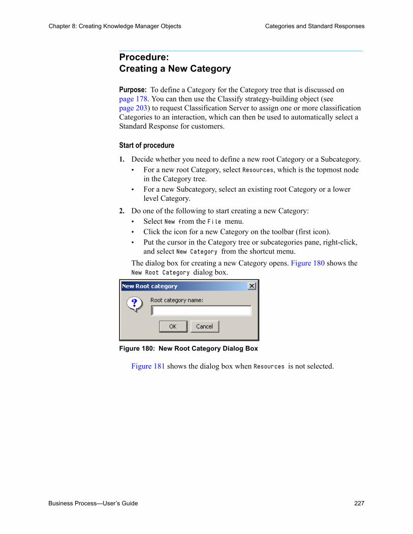
Business Process—User’s Guide 227
Chapter 8: Creating Knowledge Manager Objects Categories and Standard Responses
Procedure:Creating a New Category
Purpose: To define a Category for the Category tree that is discussed on page 178. You can then use the Classify strategy-building object (see page 203) to request Classification Server to assign one or more classification Categories to an interaction, which can then be used to automatically select a Standard Response for customers.
Start of procedure
1. Decide whether you need to define a new root Category or a Subcategory. For a new root Category, select Resources, which is the topmost node
in the Category tree. For a new Subcategory, select an existing root Category or a lower
level Category.
2. Do one of the following to start creating a new Category: Select New from the File menu. Click the icon for a new Category on the toolbar (first icon). Put the cursor in the Category tree or subcategories pane, right-click,
and select New Category from the shortcut menu.
The dialog box for creating a new Category opens. Figure 180 shows the New Root Category dialog box.
Figure 180: New Root Category Dialog Box
Figure 181 shows the dialog box when Resources is not selected.
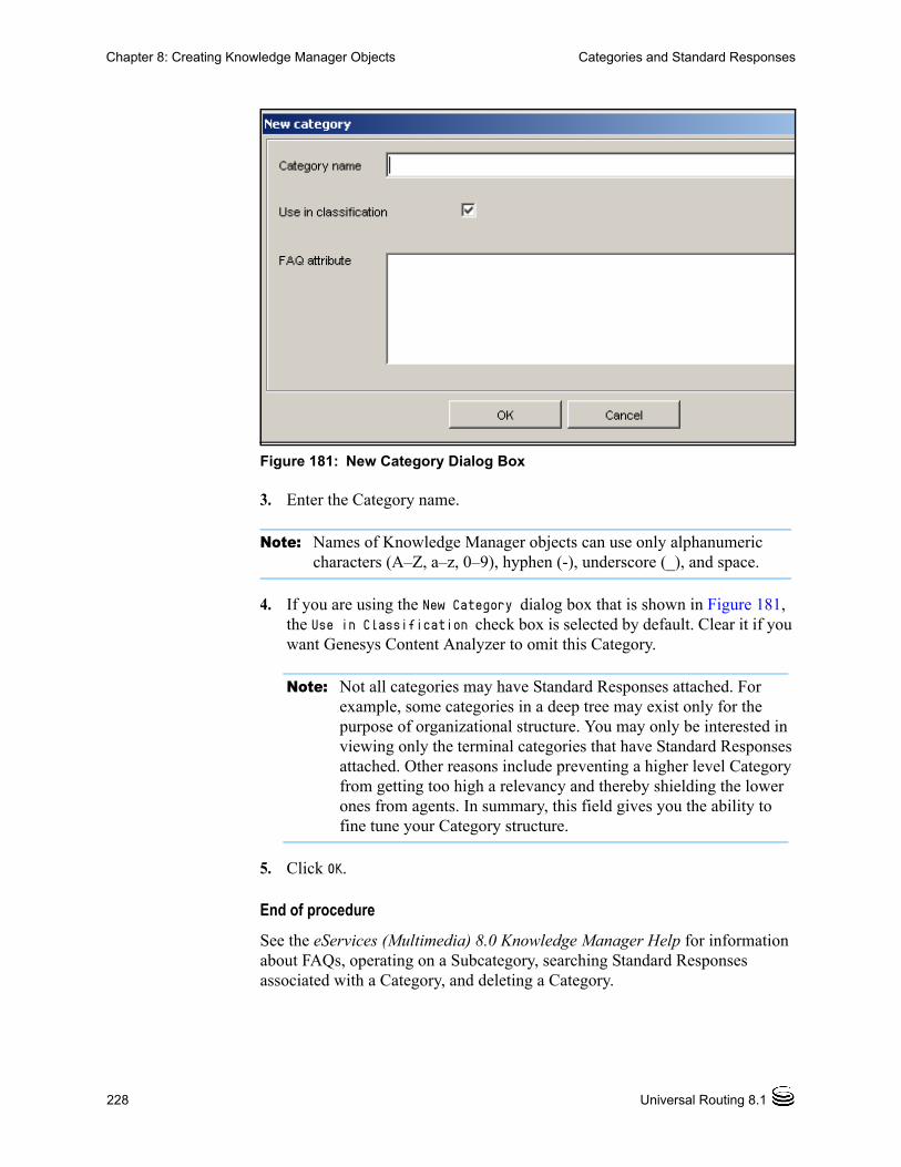
228 Universal Routing 8.1
Chapter 8: Creating Knowledge Manager Objects Categories and Standard Responses
Figure 181: New Category Dialog Box
3. Enter the Category name.
Note: Names of Knowledge Manager objects can use only alphanumeric characters (A–Z, a–z, 0–9), hyphen (-), underscore (_), and space.
4. If you are using the New Category dialog box that is shown in Figure 181, the Use in Classification check box is selected by default. Clear it if you want Genesys Content Analyzer to omit this Category.
Note: Not all categories may have Standard Responses attached. For example, some categories in a deep tree may exist only for the purpose of organizational structure. You may only be interested in viewing only the terminal categories that have Standard Responses attached. Other reasons include preventing a higher level Category from getting too high a relevancy and thereby shielding the lower ones from agents. In summary, this field gives you the ability to fine tune your Category structure.
5. Click OK.
End of procedure
See the eServices (Multimedia) 8.0 Knowledge Manager Help for information about FAQs, operating on a Subcategory, searching Standard Responses associated with a Category, and deleting a Category.
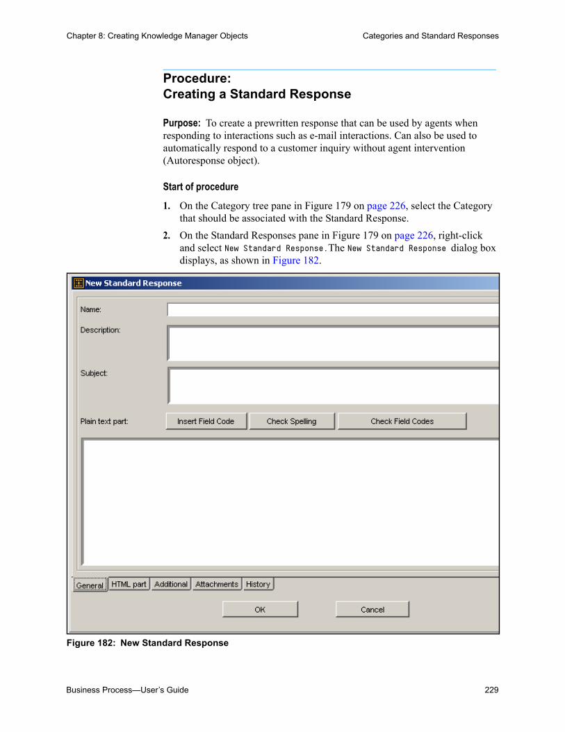
Business Process—User’s Guide 229
Chapter 8: Creating Knowledge Manager Objects Categories and Standard Responses
Procedure:Creating a Standard Response
Purpose: To create a prewritten response that can be used by agents when responding to interactions such as e-mail interactions. Can also be used to automatically respond to a customer inquiry without agent intervention (Autoresponse object).
Start of procedure
1. On the Category tree pane in Figure 179 on page 226, select the Category that should be associated with the Standard Response.
2. On the Standard Responses pane in Figure 179 on page 226, right-click and select New Standard Response.The New Standard Response dialog box displays, as shown in Figure 182.
Figure 182: New Standard Response

230 Universal Routing 8.1
Chapter 8: Creating Knowledge Manager Objects Creating Field Codes
Note: The title of the Standard Response editor dialog box is New Standard Response if you are creating a Standard Response and Edit Standard Response if you are editing an existing Standard Response. The contents are otherwise identical.
Note the General tab in Figure 182 on page 229. To complete the General tab:
3. Enter a name (required) and description (optional) for the Standard Response. Remember that the name can only use alphanumeric characters (A–Z, a–z, 0–9), hyphen, underscore, and space.
4. Enter a subject for the Standard Response. What you enter here appears as the Subject line in an e-mail (acknowledgement or autoresponse) generated from this Standard Response.
5. Enter text for the plain text version of the Standard Response, using the Insert Field Code button to insert Field Codes. If you have not yet created Field Codes, you can continue creating the Standard Response, then return to it and insert Field Codes after you have created them.
6. Use the relevant buttons to check spelling and Field Codes. Checking Field Codes shows you the result of applying (rendering) the Field Codes in this Standard Response. The values that are rendered are taken from a collection of generic properties that exists for this purpose.
End of procedure
For information about the remaining elements in the General tab, as well as the Additional, Attachments, and History tabs, see the eServices (Multimedia) 8.0 User’s Guide.
Note: When E-mail Server uses the Standard Response to create an e-mail (as when generating an acknowledgment, for example), it creates a multipart e-mail that includes both plain text and HTML versions. Then the settings of the e-mail client that receives the e-mail determine the version that is displayed. For more information, see the eServices (Multimedia) 8.0 User’s Guide.
Creating Field CodesThe IRD Acknowledgement and Autoresponse objects allow you to specify Standard Responses, which can contain Field Codes (see Figure 165 on page 182 and Figure 169 on page 185). The Knowledge Manager Field Codes tab shows the name, description, and body of all Field Codes currently in the Universal Contact Server Database. Figure 183 shows an example tab.

Business Process—User’s Guide 231
Chapter 8: Creating Knowledge Manager Objects Creating Field Codes
Figure 183: Knowledge Manager Field Codes Tab
Procedure:Creating a Field Code
Purpose: To create a Field Code to customize a Standard Response—usually for a particular customer.
Start of procedure
1. Click the Field Codes tab in the Knowledge Manager main window.
2. Click the icon on the toolbar for a new Field Code (the first icon, as shown in Figure 183). This brings up the New Field Code dialog box (see Figure 184).
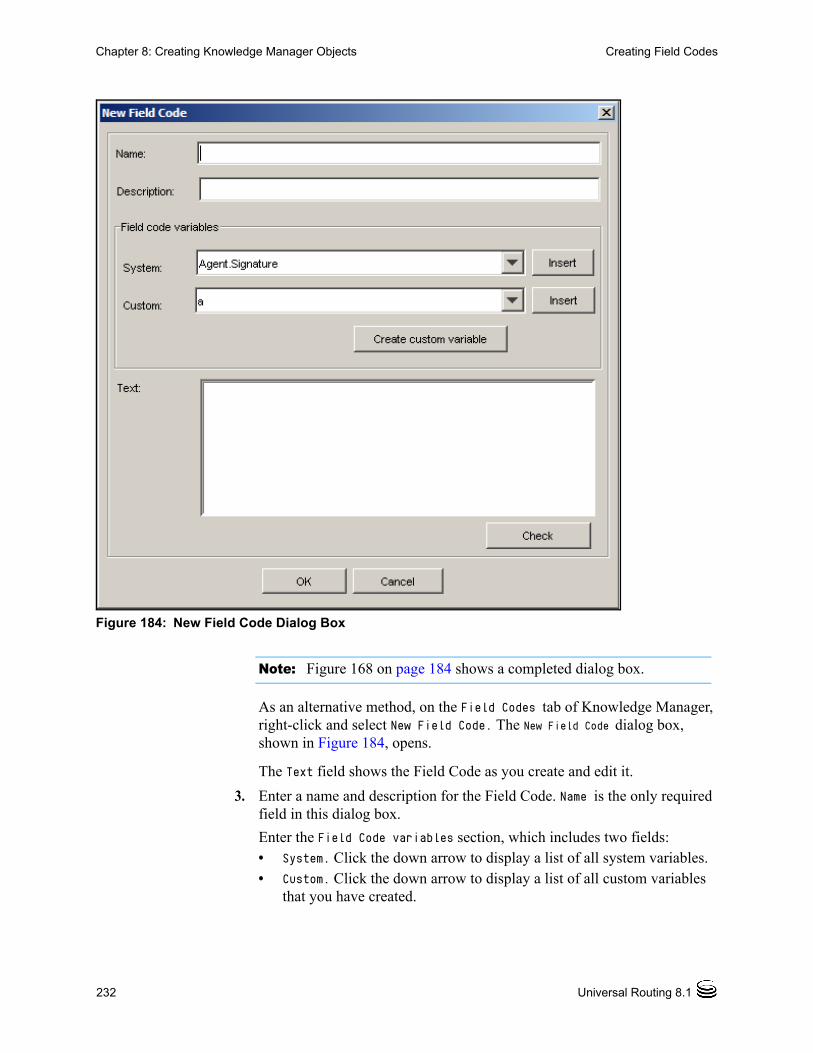
232 Universal Routing 8.1
Chapter 8: Creating Knowledge Manager Objects Creating Field Codes
Figure 184: New Field Code Dialog Box
Note: Figure 168 on page 184 shows a completed dialog box.
As an alternative method, on the Field Codes tab of Knowledge Manager, right-click and select New Field Code. The New Field Code dialog box, shown in Figure 184, opens.
The Text field shows the Field Code as you create and edit it.
3. Enter a name and description for the Field Code. Name is the only required field in this dialog box.
Enter the Field Code variables section, which includes two fields:• System. Click the down arrow to display a list of all system variables. • Custom. Click the down arrow to display a list of all custom variables
that you have created.

Business Process—User’s Guide 233
Chapter 8: Creating Knowledge Manager Objects Creating Screening Rules
4. To create a new Field Code, click Create custom variable.The New Custom Variable dialog box opens (see Figure 185).
Figure 185: New Custom Variable
5. For information about creating Custom Variables, see the eServices (Multimedia) 8.0 User’s Guide. Also see that guide for information about the following:• Inserting Field Codes into a Standard Response.• Editing an Existing Field Code.
6. Click OK.
End of procedure
Creating Screening RulesNote: To review the difference between screening and classification, see
Table 5 on page 176.

234 Universal Routing 8.1
Chapter 8: Creating Knowledge Manager Objects Creating Screening Rules
When constructing a routing strategy that screens e-mails for certain words or word patterns, you use the Screen or Multi-Screen IRD object. Each of these objects requires Screening Rules, which must be set up in Knowledge Manager in order to be selectable from the object dropdown menus.
Figure 186 shows the Screening tab of Knowledge Manager filled in with sample Screening Rules.
Figure 186: Knowledge Manager Screening Tab
Procedure:Creating a Screening Rule
Purpose:
To create or edit a Screening Rule that can be used in the Screen or MultiScreen IRD strategy object to filter interactions for specific words or word patterns.

Business Process—User’s Guide 235
Chapter 8: Creating Knowledge Manager Objects Creating Screening Rules
Start of procedure
1. Go to the Screening tab in the Knowledge Manager main window (see Figure 186 on page 234).
2. Do one of the following:
a. Select New from the File menu.
b. Right-click anywhere on the Screening tab and select New.
c. Select an existing Screening Rule and double-click or select Edit from the File menu.
The Screening Rule dialog box opens, as shown in Figure 187.
Figure 187: New Screening Rule Dialog Box
Note: In the case of Steps 2a or 2b, its title is New Screening Rule; in the case of Step 2c, its title is Edit Screening Rule.
3. Complete this dialog box using the detailed instructions on creating a Screening Rule found in the eServices (Multimedia) 8.0 User’s Guide.
End of procedure

236 Universal Routing 8.1
Chapter 8: Creating Knowledge Manager Objects Creating Screening Rules
Notes: To obtain all available screening functionality, Genesys recommends that you use the MultiScreen object instead of the Screen object. Use the Screen object for backward compatibility only (for example, for 7.0 backward compatibility).
When you first start creating routing strategies, you might want to use the Screen object instead of the Classify object if your site’s classification Categories are not yet defined or if your site has not purchased the Content Analysis option required by the Classify IRD object.

Business Process—User’s Guide 237
Chapter
9 Creating Configuration Manager ObjectsThis chapter provides step-by-step instructions for creating Configuration Manager objects that are used by IRD’s strategy-building objects. It contains the following sections: Opening Configuration Manager, page 237 Defining Skills, page 239 Defining Persons, page 241 Defining Agent Groups, Places, and Place Groups, page 243 Defining Business Attributes, page 243
For background information, see “Configuration Layer Interface” on page 155.
Opening Configuration ManagerThe information in this section assumes you have already set up the Genesys Configuration Layer as described in Framework 8.1 Deployment Guide.
Procedure:Logging into Configuration Manager
Start of procedure
1. Click the desktop shortcut if one appears (see Figure 188).
Figure 188: Configuration Manager Desktop Icon

238 Universal Routing 8.1
Chapter 9: Creating Configuration Manager Objects Opening Configuration Manager
As an alternative, use the Start button and select Programs > Genesys Solutions > Framework > Configuration Manager.
2. Respond to any security-related screens that your company may have configured to appear before the Configuration Manager login dialog box. The Configuration Manager login dialog box appears as shown in Figure 189.
Figure 189: Configuration Manager Login Dialog Box
3. Use the information in Table 20 to complete the Configuration Manager login dialog box:
Table 20: Configuration Manager Login Dialog Box
Field Description
User name: Name of the Person object that is defined in Configuration Manager.
User password: Password of the Person object that is defined in Configuration Manager.
Application: Use default to have the Application object selected automatically or enter the name of an Configuration Manager Application object.
Host name: Name of computer on which Configuration Server is located.
Port: Port number that is used by Configuration Server. By default, this value is 2020.

Business Process—User’s Guide 239
Chapter 9: Creating Configuration Manager Objects Defining Skills
4. Click OK. Configuration Manager opens (see “Environment Folder and Tenants” on page 156).
5. If working in a Multi-Tenant environment, select a Tenant object (one of the tenants is named Environment).
End of procedure
Note: All figures in this chapter are based on a Multi-Tenant environment.
Defining SkillsIf you plan to route based on agent skills or skill levels, you must first create Skill objects and then assign those Skill objects to agents (Persons).
Procedure:Defining Skill objects that can be assigned to agents
Start of procedure
1. Log in to Configuration Manager, as described on page 237.
2. Expand the Resources folder.
3. Right-click the Skills folder and select New > Skill. The New Skill Properties dialog box opens (see Figure 190).

240 Universal Routing 8.1
Chapter 9: Creating Configuration Manager Objects Defining Skills
Figure 190: Skill Properties Dialog Box
4. Type the Skill name. Examples: Email, Chat, English, Spanish, New Accounts, Existing Accounts.
5. Leave State Enabled checked.
6. The Annex tab is not required (if it does not display, select View > Options.
Note: Annex is an additional data structure Genesys uses to quickly introduce additional information properties for any object. Annex describes such properties as simple text options arranged in sections, where each section typically relates to the product that uses this set of properties.You can find information about when and how to add and change information in Annexes in the configuration sections of application-specific manuals.
7. Click OK in the properties dialog box.
8. Continue defining Skills in this manner.
End of procedure
Note: In addition to assigning Skills to agent Persons as described below, you can also route based on the value of a skill expression (see Figure 121 on page 138).

Business Process—User’s Guide 241
Chapter 9: Creating Configuration Manager Objects Defining Persons
Defining PersonsOnce you have defined Skills, you can assign them to Persons, such as agents, QA, managers, and supervisors. You can then route interactions to Persons that have specific Skills and Skill Levels.
Procedure:Defining Person objects
Purpose: To represent agents that can be routed to in the Configuration Database.
Start of procedure
1. Log into Configuration Manager as described on page 237.
2. Under Resources, right-click the Persons folder and select New > Person. The New Person Properties dialog box opens (see Figure 191).
Figure 191: New Persons Dialog Box, General Tab

242 Universal Routing 8.1
Chapter 9: Creating Configuration Manager Objects Defining Persons
3. Complete the General tab. If you need help, click the Configuration Manager Help menu and select Help Topics.
4. Click the Agent Info tab. Figure 192 on page 242 shows the dialog box filled in with sample data.
Figure 192: Person Dialog Box, Agent Info Tab
5. Complete the Agent Info tab. Click the Add Skill button to add a previously defined agent skill. If you need help, click the Configuration Manager Help menu and select Help Topics.
Note: If applicable, you can assign a Capacity Rule to the agent, which defines the agent’s ability to handle multiple interactions. For more information, see “Agent Capacity Rules” on page 164.
6. Click the Security tab.
7. Click the Permissions button in the Security tab and assign permissions (see “Setting Permissions” on page 173). Figure 193 shows the dialog box filled in with sample data.

Business Process—User’s Guide 243
Chapter 9: Creating Configuration Manager Objects Defining Agent Groups, Places, and Place Groups
Figure 193: Object Permissions Dialog Box
8. When you are finished defining permissions, click OK to save in the Object Permission dialog box.
9. Click OK in the New Person properties dialog box.
End of procedure
Defining Agent Groups, Places, and Place Groups
Once you have defined Persons, define Agent Groups and assign Persons to each group. You only need to do this if you plan to route to agent groups. After completing the previous sections, you now understand how to create new objects in Configuration Manager:
1. Log into Configuration Manager as described on page 237.
2. Under Resources, right-click the object and select New <object_name> to open the properties dialog box.
3. Complete the properties dialog box.
4. Click OK to save your entries.
Defining Business AttributesThe Resources folder contains a Business Attributes folder. Figure 146 on page 162 shows the folder expanded.
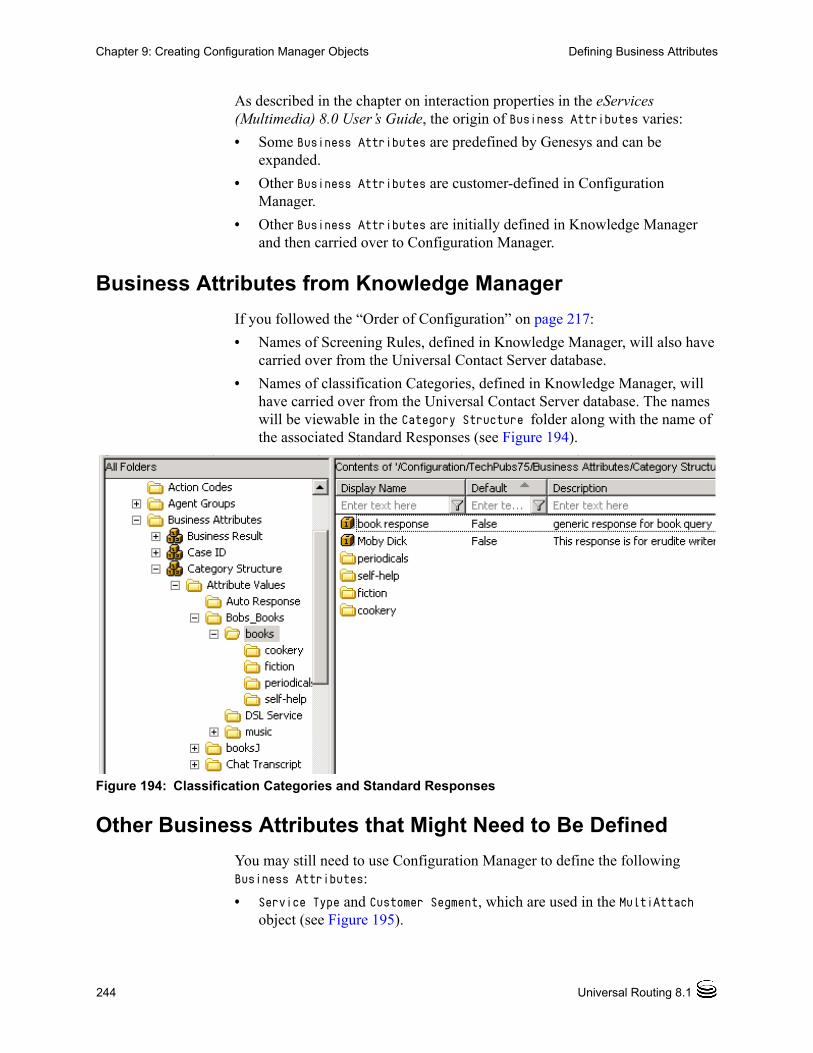
244 Universal Routing 8.1
Chapter 9: Creating Configuration Manager Objects Defining Business Attributes
As described in the chapter on interaction properties in the eServices (Multimedia) 8.0 User’s Guide, the origin of Business Attributes varies:
• Some Business Attributes are predefined by Genesys and can be expanded.
• Other Business Attributes are customer-defined in Configuration Manager.
• Other Business Attributes are initially defined in Knowledge Manager and then carried over to Configuration Manager.
Business Attributes from Knowledge Manager
If you followed the “Order of Configuration” on page 217:
• Names of Screening Rules, defined in Knowledge Manager, will also have carried over from the Universal Contact Server database.
• Names of classification Categories, defined in Knowledge Manager, will have carried over from the Universal Contact Server database. The names will be viewable in the Category Structure folder along with the name of the associated Standard Responses (see Figure 194).
Figure 194: Classification Categories and Standard Responses
Other Business Attributes that Might Need to Be Defined
You may still need to use Configuration Manager to define the following Business Attributes:
• Service Type and Customer Segment, which are used in the MultiAttach object (see Figure 195).

Business Process—User’s Guide 245
Chapter 9: Creating Configuration Manager Objects Defining Business Attributes
Figure 195: Multi-Attach Object Properties Dialog Box
The above three attributes are described in the chapter on IRD objects, MultiAttach object section, in the Universal Routing 8.1 Reference Manual.
Note: ServiceObjective is defined outside of the Business Attributes folder under Objective Tables.
• Disposition Code. Currently not used by any IRD object, but contained in the Interactions table.
• Language. The primary motivation for creating is the necessity to use this Business Attribute in conjunction with some particular Tenant in Knowledge Manager. All objects in Knowledge Manager, including classification Categories and Screening Rules, can only be created under specific combination of Language and Tenant. The following IRD objects use the Language Business Attribute: Screen, Multi-Screen, and Screen Segmentation. For more information about this attribute, see the chapter on interaction properties in the eServices (Multimedia) 8.0 User’s Guide.
• PIN. Currently not used by any IRD object, but you might want to include in interactions.
246 Universal Routing 8.1
Chapter 9: Creating Configuration Manager Objects Defining Business Attributes
• Reason Code and Stop Processing Reason, when you are using the IRD Stop object that is described in Table 8 on page 201. For more information about Reason Codes, see the Stop Interaction object description in the chapter on IRD objects of this guide.
• As described in the Universal Routing 8.1 Reference Manual, E-mail Accounts specifies an external e-mail address that is required when you are using the following IRD objects: Acknowledgement, Autoresponse, Chat Transcript, Create Notification, Create SMS, Forward E-mail, Redirect E-mail, Reply From External Resource, and Send E-mail. See Table 8 on page 201.
For additional information about E-mail Accounts, see the chapter on preparing your environment for Genesys Desktop in the Genesys Desktop 7.6 Deployment Guide. Also see description for the E-mail Server option convert-idn-to-unicode in eServices (Multimedia) 8.0 Reference Guide.
• Media Type. When you are implementing the Genesys Open Media concept, another Business Attribute that you might want to create is a custom Media Type that will be added to the Genesys predefined set of Media Types. A service that is performed by some third party server that is associated with a custom Media Type could be used in the External Service object that is described in Table 8 on page 201.
• Contact Attributes. See the topic on matching contact attributes in the eServices (Multimedia) 8.0 User’s Guide. Also see the chapter on contact identification and creation in that guide.

Business Process—User’s Guide 247
hapter
10 Creating Business Process ObjectsThis chapter provides step-by-step instructions for starting a new business process, including adding Queue, View, and Workbin objects, and Strategy object placeholders.
This chapter includes the following sections: Distribution of Load Between Multiple Interactions Servers,
page 315Simple Versus Complex, page 247 Defining the Business Process Object, page 248 Using Media Server Objects, page 252 Adding Endpoints, page 254 Adding a Queue, page 258 Adding a Synthetic Queue, page 262 Adding a View, page 267 Adding Workbins, page 292 Strategy Placeholder Option, page 299 Adding a Submitter, page 303 About Connector Lines, page 305 Exporting and Importing a Business Process, page 306 Distribution of Load Between Multiple Interactions Servers,
page 315Simple Versus Complex
The chapter “Planning a Business Process” on page 195 discusses two types of business processes:
1. A complex business process that encompasses many different functional areas, such as the Genesys-supplied Default_BP (see Figure 174 on page 198).
Note: See “Order of Configuration” on page 217.
248 Universal Routing 8.1
hapter 10: Creating Business Process Objects Defining the Business Process Object
2. Smaller, less complex business processes, each of which encompass a single functional area, such as the Genesys-supplied step-numbered business processes (see Figure 175 on page 199).
This guide assumes that, as a new user, you will create smaller, less complex business processes and connect them via queues. This chapter assumes that you want to create something similar to the Step 1. Pre-Routing business process that is shown in Figure 175 on page 199.
Defining the Business Process ObjectNote: When you run IRD on a clean configuration, it automatically creates a
default Business Process object for you, which you can rename or use to create other Business Process objects. The instructions and figures in this section assume that you do not have a clean computer, but that you have loaded the samples as described in “Using the Samples” on page 197.
Procedure:Defining a Business Process Script object
Purpose: To define the Business Process Script object in Configuration Layer.
Start of procedure
1. Log in as described in “Opening IRD” on page 57.
2. Click the Interaction Design shortcut bar on the left.
3. Click the Business Process icon. Existing business processes are listed for selection as shown in Figure 35 on page 60.
4. If a folder is already selected, from the File menu, click New. You can also right-click any folder on the list pane and select New; The New dialog box opens. A temporary name for the business process appears in the browser as shown in Figure 196.

Business Process—User’s Guide 249
hapter 10: Creating Business Process Objects Defining the Business Process Object
Figure 196: New Business Process with Temporary Name
5. Select (slowly double-click) temporary name and replace it, supplying the name that is to be used for the Script object (see Figure 143 on page 159).
Assume that you enter Preprocessing. Because the browser lists business processes in alphabetical order, it now appears as shown in Figure 197.
Figure 197: Business Process Renamed
Note: If you change your mind at any point, click the Edit menu and select Undo Creating or Undo Updating.
renamed business process

250 Universal Routing 8.1
hapter 10: Creating Business Process Objects Defining the Business Process Object
6. Right-click the business process and select Properties from the shortcut menu. The Business Process Properties dialog box opens (see Figure 198).
Figure 198: Business Process Dialog Box
7. In this dialog box, describe the business process.
8. A Business Process can be the default Business Process for the Tenant by selecting the Default check box. The configuration of the default Queue and default Business Process simplifies Media Server configuration, and enables interactions to be submitted without having to specify the initial interaction queue. Only one Business Process within a Tenant can be set as default.
9. After completing the dialog box, click its upper-right corner. The new Business Process object remains selected in the viewer.
Note: See the eServices documentation to develop a Media Server object that takes advantage of the default Business Process and default Queue configuration.

Business Process—User’s Guide 251
hapter 10: Creating Business Process Objects Defining the Business Process Object
10. Select Save from the File menu. This creates a new Script object in the Configuration Database of type Business Process (see Figure 143 on page 159). You can still change the name in the Interaction Design window as shown in Figure 73 on page 89.
End of procedure
Warning! Do not use Configuration Manager to manually create business process and the other Script objects described in this guide. To ensure database integrity, use only IRD to create these objects.
Procedure:Deleting a previously saved business process
Warning! If you do not want to delete the strategies that are associated with a business process, move them to the Independent Objects folder (see Figure 38 on page 63) before you delete the business process.
If you have not yet saved the business process, you can delete it by exiting the Interaction Design window and clicking no to the prompt indicating that the configuration has been changed.
Start of procedure
1. To delete a business process, right-click it in the object browser.
2. Select Delete from the shortcut menu. If the business process was previously saved, the message shown in Figure 199 appears.
Notes: To switch to another business process, save the changes in the current business process, and double-click the business process you want to switch to.
Unlike the Routing Design window, the Interaction Design window does not allow you to save a business process within a tree of customized folders/subfolders, which is then viewable on an IRD list pane. You may save a business process only in the predefined default Scripts folder (see Figure 35 on page 60).
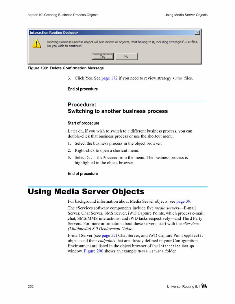
252 Universal Routing 8.1
hapter 10: Creating Business Process Objects Using Media Server Objects
Figure 199: Delete Confirmation Message
3. Click Yes. See page 172 if you need to review strategy *.rbn files.
End of procedure
Procedure:Switching to another business process
Start of procedure
Later on, if you wish to switch to a different business process, you can double-click that business process or use the shortcut menu:
1. Select the business process in the object browser,
2. Right-click to open a shortcut menu.
3. Select Open the Process from the menu. The business process is highlighted in the object browser.
End of procedure
Using Media Server ObjectsFor background information about Media Server objects, see page 39.
The eServices software components include five media servers—E-mail Server, Chat Server, SMS Server, iWD Capture Points, which process e-mail, chat, SMS/MMS interactions, and iWD tasks respectively—and Third Party Servers. For more information about these servers, start with the eServices (Multimedia) 8.0 Deployment Guide.
E-mail Server (see page 52) Chat Server, and iWD Capture Point Application objects and their endpoints that are already defined in your Configuration Environment are listed in the object browser of the Interaction Design window. Figure 200 shows an example Media Servers folder.

Business Process—User’s Guide 253
hapter 10: Creating Business Process Objects Using Media Server Objects
Figure 200: Media Servers and Endpoints in Object Browser
In the example in Figure 200, there are three Media Server objects: ChatServer, E-MailServer and EmailServerJava_760. Note the arrow-shaped objects under each media server. These are Endpoint objects (see page 41 if you need a review).
Placing a Media Server Object
To get interactions of a particular media type into a business process, you have the option of placing a Media Server object, and then connecting some or all of its endpoints to queues. After you do this, you can continue processing the media server’s interactions in the current business process and in subsequent business processes. Follow these steps:
1. First determine whether the Media Server object has already been placed in the workflow via a previously configured business process. If yes, continue with “Adding Endpoints”. If no, continue with step 2.
Endpoints

254 Universal Routing 8.1
hapter 10: Creating Business Process Objects Adding Endpoints
2. To place a Media Server object in this particular business process, drag the Media Server object from the object browser and drop it into the workflow viewer.
Adding EndpointsYou may or may not need to configure additional endpoints for your media server in order to get interactions into the proper queue. To determine this, review the information in “Media Server Object” on page 39 and “Endpoint Object” on page 41.
Note: You can add endpoints before or after you drag a Media Server object into a business process. Endpoints added to a Media Server in the object browser automatically appear in the workflow viewer.
Procedure:Adding endpoints
Purpose: To connect a media server and its interactions with a queue in a business process.
Start of procedure
1. Select Add Endpoint by using one of the following methods: From the shortcut menu that appears when you open the Media Servers
folder in the object browser and right-click a media server. From the shortcut menu that appears when you right-click a media
server in the workflow viewer (if a media server has already been placed there).
From the Business Process menu, when you select a media server in the object browser or workflow viewer.
The new Endpoint object appears in the object browser with a temporary name, which you can edit (see Figure 201).

Business Process—User’s Guide 255
hapter 10: Creating Business Process Objects Adding Endpoints
Figure 201: Object Browser After Selecting Add Endpoint
If the media server is already in the workflow viewer, the new endpoint with its temporary name appears there as a port on the right side of the media server (see Figure 202).
Figure 202: Workflow Viewer After Selecting Add Endpoint

256 Universal Routing 8.1
hapter 10: Creating Business Process Objects Adding Endpoints
2. Select (slowly double-click) the temporary name to edit it. You have the option of supplying a more descriptive name. Assume you name it ProductB. IRD moves the endpoint down to maintain alphabetical order.
3. Save the business process as it exists so far.
4. Define the queue to be connected to the endpoint (see “Adding a Queue” on page 258). Assume you name it ProductB.
5. Connect the endpoint(s) to the queue(s). Figure 203 shows the endpoint connected to a queue.
Figure 203: Media Server Endpoint Connected to Queue
Note: If an endpoint is used in another business process, IRD allows you to draw the connector. In the business process where the endpoint was previously used, IRD outlines the endpoint in red and no longer shows connector. This ensures a single endpoint is only connected to a single queue.
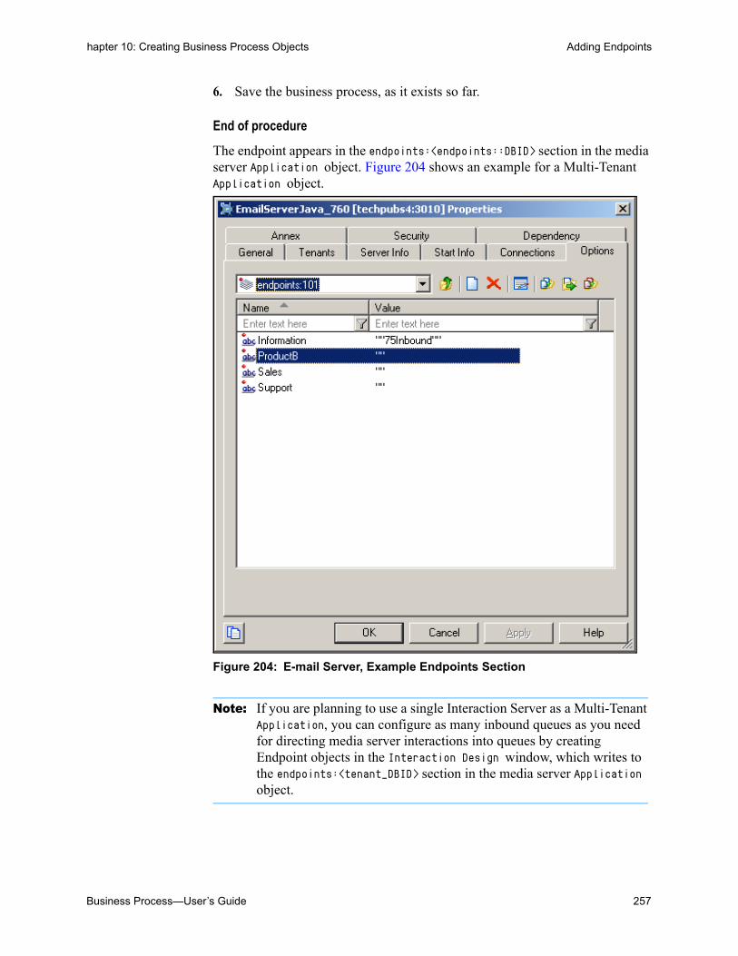
Business Process—User’s Guide 257
hapter 10: Creating Business Process Objects Adding Endpoints
6. Save the business process, as it exists so far.
End of procedure
The endpoint appears in the endpoints:<endpoints::DBID> section in the media server Application object. Figure 204 shows an example for a Multi-Tenant Application object.
Figure 204: E-mail Server, Example Endpoints Section
Note: If you are planning to use a single Interaction Server as a Multi-Tenant Application, you can configure as many inbound queues as you need for directing media server interactions into queues by creating Endpoint objects in the Interaction Design window, which writes to the endpoints:<tenant_DBID> section in the media server Application object.

258 Universal Routing 8.1
hapter 10: Creating Business Process Objects Adding a Queue
Adding a QueueFor background information about Queue objects, see page 27. For information about connector lines, see page 305.
The next step is to define a Queue object. For information about the initial inbound queue, see Figure 3 on page 23.
Procedure:Adding a Queue object
Purpose: Associating a Queue object with a business process.
The following instructions assume that you are continuing from the previous section.
Start of procedure
1. Click the Business Process menu.
2. Select New Queue. A new Queue object appears in the object browser with a temporary name (see Figure 205).
Figure 205: New Queue with Temporary Name
3. Select (slowly double-click) the temporary name and replace it with the name to be used for the Script object (see Figure 143 on page 159). Figure 206 shows the queue as it appears in the Object Browser after it has been renamed.

Business Process—User’s Guide 259
hapter 10: Creating Business Process Objects Adding a Queue
Figure 206: New Queue Renamed
4. Drag the Queue object to the viewer and drop it there (see Figure 207).
Figure 207: Queue in Workflow Viewer
5. Right-click the Queue object in the right pane and select Properties of and then select the queue name. The Queue Properties dialog box opens (see Figure 208).

260 Universal Routing 8.1
hapter 10: Creating Business Process Objects Adding a Queue
Figure 208: Queue Properties Dialog Box, General Tab
Note: You can also enable/disable Queue objects the same as any other object in Configuration Manager.
The Used In tab names the business process in which the queue is used.
Figure 209: Queue Properties Dialog Box, Used In Tab
6. Use the information in Table 21 to complete the General tab of the Queue Properties dialog box:

Business Process—User’s Guide 261
hapter 10: Creating Business Process Objects Adding a Queue
7. If this queue will receive media server interactions via an Endpoint object, connect the Endpoint object to the Queue object (see Figure 210).
Figure 210: Media Server Endpoint Connected to Queue
8. Select Save from the File menu.
End of procedure
Later, when creating routing strategies, the queue will be selectable in the properties dialog box for all IRD objects that let you select queues, such as
Table 21: Queue Properties Dialog Box
Field Description
Script Name Reflects the name that is entered in the object browser. When you save, the definition will be saved as a Script of type Interaction Queue in the Configuration Database (see Figure 143 on page 159).
Description Describe the queue.
Enabled After activating strategies as described on page 361, open the Queue Properties dialog box and select the Enabled check box to specify the queue state as ready to accept interactions. The default is checked (enabled).

262 Universal Routing 8.1
hapter 10: Creating Business Process Objects Adding a Synthetic Queue
Queue Interaction. You will find it under the associated business process (see Figure 211).
Figure 211: Queues Available for Selection
Note: Be sure that you define separate interaction queues and workbins for each Open Media type.
Adding a Synthetic QueueA synthetic queue is a queue that is composed of multiple interaction queues. Creating a synthetic queue simplifies workflow configuration by enabling you to specify interaction processing by multiple queues in a single step.
Three types of synthetic queues can be created: Business Process Queue—represents interactions located in any
queue that belongs to the same Business Process as the Business Process queue. A Business Process Queue can be used to define processing for all interactions of a given Business Process.

Business Process—User’s Guide 263
hapter 10: Creating Business Process Objects Adding a Synthetic Queue
Synthetic Queue—represents interactions located in any queue that is listed in the Synthetic Queue configuration. A Synthetic Queue can be used to define processing for all interactions in a specific group of Interaction Queues.
Tenant Queue—represents interactions located in any queue that belongs to the same tenant as the Tenant Queue. A Tenant Queue can be used to define processing for all interactions that belong to a tenant.
Procedure:Adding a Synthetic Queue object
Purpose: To associate a Synthetic Queue object with a business process.
The following instructions assume that you are continuing from the previous section.
Start of procedure
1. Click the Business Process menu.
2. Select New Synthetic Queue.
3. In the Type drop-down list, select the synthetic queue type for this synthetic queue (Business Process, Synthetic, or Tenant, as described above), then click OK.
4. A new Queue object appears in the object browser with a temporary name (see Figure 212).
Figure 212: New Synthetic Queue with Temporary Name

264 Universal Routing 8.1
hapter 10: Creating Business Process Objects Adding a Synthetic Queue
5. Select (slowly double-click) the temporary name and replace it with the name to be used for the Script object (see Figure 143 on page 159). Figure 213 shows the synthetic queue as it appears in the Object Browser after it has been renamed.
Figure 213: New Synthetic Queue Renamed
6. Drag the Synthetic Queue object to the viewer and drop it there (see Figure 214).
Figure 214: Synthetic Queue in Workflow Viewer

Business Process—User’s Guide 265
hapter 10: Creating Business Process Objects Adding a Synthetic Queue
7. Right-click the Synthetic Queue object in the right pane and select Properties. The Interaction Queue Properties dialog box opens (see Figure 215, Figure 216, and Figure 217).
Figure 215: Synthetic Queue Properties Dialog Box, General Tab
Figure 216: Synthetic Queue Properties Dialog Box, Used In Tab

266 Universal Routing 8.1
hapter 10: Creating Business Process Objects Adding a Synthetic Queue
Figure 217: Synthetic Queue Properties Dialog Box, Queues Tab
8. Use the information in Table 22 to set values in the Interaction Queue Properties Dialog box.
9. If this queue will receive media server interactions via an Endpoint object, connect the Endpoint object to the Queue object (see Figure 210 on page 261 for an example).
Table 22: Synthetic Queue Properties Dialog Box
Tab Field Description
General (All Synthetic Queue Types)
Script Name (Read-only) Displays the name that you assigned to the synthetic queue in the Object Browser. When you save, the definition will be saved as a Script of type Interaction Queue in the Configuration Database (see Figure 143 on page 159).
Description Describe the synthetic queue.
Enabled After activating strategies as described on page 361, open the Queue Properties dialog box and select the Enabled check box to specify the synthetic queue state as ready to accept interactions. The default is checked (enabled).
Used In (All Synthetic Queue Types)
This read-only tab lists the Business Processes in which this synthetic queue has been placed.
Queues (“Synthetic” Type Only)
Select the interaction queues to be included in this synthetic queue from the tree on this tab. The interaction queues are listed under the Business Processes in which they were initially configured.

Business Process—User’s Guide 267
hapter 10: Creating Business Process Objects Adding a View
10. Select Save from the File menu.
End of procedure
Later, when creating routing strategies, the queue will be selectable in the properties dialog box for all IRD objects that let you select queues, such as Queue Interaction. You will find it under the associated business process (see Figure 211 on page 262).
Adding a ViewFor background information about View objects, see page 28. For information about connector lines, see page 305. A View object allows you to define one or more of the following:
• The name for the View object in the Configuration Manager Scripts folder (see page 271)
• The conditions for interaction selection including parameterized conditions, such as those that are used by Agent Desktop (see pages 272 and 282)
• The order of interaction selection (see page 274)
• The time interval that Interaction Server uses to check for interactions (page 275)
• The schedule for submitting interactions to strategies (see page 275).
• Database hints (see page 283)
• The number of interactions of different segments (see page 284)
In addition, you can use Configuration Manager to limit the number of interactions based on interaction properties, such as Customer Segment (see page 287).
You can set other values in the Interaction Server Application object, as described in the chapter on configuration options in the eServices (Multimedia) 8.0 Reference Manual.
Same Queue, Multiple Views
You can define multiple View objects for a single queue or workbin. The examples that follow use queues. For an example of a view attached to a workbin, see “How To: Apply Escalation Procedure” on page 411.
Example #1
You must define multiple views for a queue if you want to deliver interactions from one queue to different routing strategies. For example, if you have E-mail Server submit all e-mails into one queue, but you have two separate

268 Universal Routing 8.1
hapter 10: Creating Business Process Objects Adding a View
strategies—one for normal e-mail and another for nondeliverable e-mail—you must define two views.
Example #2
You might want to define multiple views for a queue for priority escalation:
• You could use one view to pull interactions for standard processing by a routing strategy that delivers interactions to agents.
• You could use a second view to select interactions for special processing by a routing strategy that changes interaction priority and then returns the interaction to the same queue.
Warning! If you configure multiple views for the same queue and the view- selection conditions overlap, more that one view could potentially select the same interaction. When configuring views, be sure conditions do not overlap. Also, make sure that conditions process all the interactions in the queue.
Procedure:Adding a View to a Queue object
Purpose: Views enable you to extract interactions from queues, either all interactions or interactions that are based on specific selection criteria.
Note: This section describes attaching a view to a queue. The instructions also apply to attaching a view to a workbin.
Start of procedure
The following instructions assume that you are continuing from the previous section.
1. Select the queue to which you want to attach the view, either in the object browser or in the workflow viewer.
2. Right-click and select New View from the shortcut menu that opens (see Figure 218). You can also select New View from the Business Process menu.
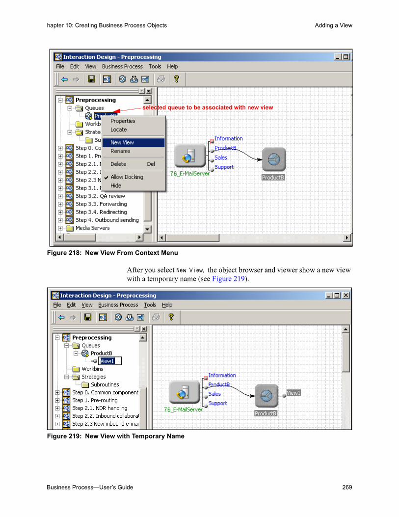
Business Process—User’s Guide 269
hapter 10: Creating Business Process Objects Adding a View
Figure 218: New View From Context Menu
After you select New View, the object browser and viewer show a new view with a temporary name (see Figure 219).
Figure 219: New View with Temporary Name
selected queue to be associated with new view

270 Universal Routing 8.1
hapter 10: Creating Business Process Objects Adding a View
3. Select (slowly double-click) the temporary name and replace it with the name to be used for the Script object.
Assume that you rename it ProdBView1
4. Double-click the small circle that represents the new view (see Figure 220).
Figure 220: New View Attached to Queue Object
The View Properties dialog box opens (see Figure 221).
Figure 221: View Properties Dialog Box, General Tab
Note: You can also enable/disable View objects the same as any other object in Configuration Manager.
End of procedure

Business Process—User’s Guide 271
hapter 10: Creating Business Process Objects Adding a View
Next Steps
• Complete the General tab (optional step).
General Tab
This section contains procedures for completing each tab in the View Properties dialog box.
Procedure:Completing the View object General tab
Purpose: To describe the view and to specify the frequency for checking the queue if the default will not be used.
Start of procedure
1. Click the General tab in the View Properties dialog box.
2. Use Table 23 to complete the General tab of the dialog box shown in Figure 221.
Table 23: View Properties Dialog Box, General Tab
Field Description
Script Name Reflects the name that is entered in the object browser. When you save, the definition will be saved as a Script of type Interaction Queue View in the Configuration Database (see Figure 143 on page 159).
Description Enter a description for the view.

272 Universal Routing 8.1
hapter 10: Creating Business Process Objects Adding a View
3. When you have finished completing the General tab, select Save from the File menu.
End of procedure
Next Steps
• Complete the Condition tab (optional step).
Condition Tab
This section describes the tab on which you specify the condition for extracting interactions from queues.
Procedure:Completing the View object Condition tab
Start of procedure
1. Click the Condition tab in the View Properties dialog box.
2. Use Table 24 to complete the Condition tab that is shown in the following figures.
Enabled After activating strategies as described on page 361, open the Queue Properties dialog box and select the Enabled check box to specify the view as ready to extract interactions. The default is checked (enabled).
Check Interval (sec) Enter the number of seconds to specify the frequency (time interval) that Interaction Server will use to check the queue and, if necessary, adjust the number of interactions that can be submitted to the strategy based on options in the Scheduling tab (Figure 225 on page 275). Acceptable values are 0~300 seconds. You might want to use this field for high-value interactions or time-sensitive conditions, such as when checking should be performed more frequently.
This field creates or updates option freeze-interval for the view. It overrides option default-view-freeze-interval (in the settings section of Interaction Server options) for the view. The freeze-interval defines how long Interaction Server suspends database checking for a view if no interactions were selected. If option freeze-interval is not present for a particular view, the value of default-view-freeze-interval is used. If option default-view-freeze-interval is not specified, Interaction Server uses the default of 300 seconds.
Table 23: View Properties Dialog Box, General Tab (Continued)
Field Description

Business Process—User’s Guide 273
hapter 10: Creating Business Process Objects Adding a View
The expression defines the conditions for interaction selection. You can specify one or more expressions, which can be comprised of: An interaction attribute name from the interactions table. eServices
(Multimedia) 8.0 User’s Guide lists and describes the interaction attributes that you can use when building an expression.
A relational operator, such as an equal sign or a greater than sign. The attribute value in single quotes.
The expression is used for interaction selection as if you were constructing a SQL SELECT statement and specifying a WHERE clause.
For a comparison of the Condition tab with the Parameterized Condition tab, see page 282.
3. When you have finished completing the Condition tab, select Save from the File menu.
End of procedure
Table 24: View Properties Dialog Box, Condition Tab
Field Description
Condition Here you have the option of creating an expression. Figure 222 shows an example from another business process.
Figure 222: Extracting Based on Customer Segment
Another example from another business process:
Figure 223: Extracting Based on Time in Queue
As an alternative to the Condition tab, the Segmentation tab (see page 285) uses a more complex approach that involves specifying limits and submitting equal numbers of interactions.

274 Universal Routing 8.1
hapter 10: Creating Business Process Objects Adding a View
Next Steps
• Complete the Order tab (optional step).
Order Tab
This section describes how to specify the order of interaction selection.
Procedure:Completing the View object Order tab
Start of procedure
1. Click the Order tab in the View Properties dialog box.
2. Use Table 25 to complete the Order tab that is shown in Figure 224.
3. When you have finished completing the Order tab, select Save from the File menu.
End of procedure
Next Steps
• Complete the Scheduling tab (optional step).
Table 25: View Properties Dialog Box, Order Tab
Field Description
Order Here you have the option of defining the order for pulling interactions from the queue when using this view.
order:= [property_order[,order]]property_order:= property_name [asc|desc]
Example using an attribute found in the interactions table.
Figure 224: Order Tab
For more information interaction attributes that can be used on the Order tab, see the section on System Properties in the chapter on Interaction Properties in the eServices (Multimedia) 8.0 User’s Guide.

Business Process—User’s Guide 275
hapter 10: Creating Business Process Objects Adding a View
Scheduling Tab
This section describes how to schedule submitting interactions to a routing strategy. You might want to do this for various reasons, such as scheduling of a customer callback or to escalate overdue interactions.
Procedure:Completing the View object Scheduling tab
Start of procedure
1. Click the Scheduling tab in the View Properties dialog box (see Figure 225).
Figure 225: Scheduling Tab
2. Use Table 26 to complete the Scheduling tab.
Table 26: View Properties Dialog Box, Scheduling Tab
Field Description
Scheduling The Scheduling tab shown in Figure 225 on page 275 lets you specify the scheduling condition that Interaction Server should use, based upon the scheduled time contained in interactions (see “Setting the ScheduledAt Property” on page 276).Background: The interaction scheduling functionality uses a database field called scheduled_at, which is mapped to an interaction property called ScheduledAt. For information about this field, see the chapter on interaction properties in the eServices (Multimedia) 8.0 User’s Guide.
Ignore Scheduling Default. Select if there is no scheduled processing. Even if the value of ScheduledAt is set for some interactions, Interaction Server ignores it.

276 Universal Routing 8.1
hapter 10: Creating Business Process Objects Adding a View
3. When you have finished completing the Scheduling tab, select Save from the File menu.
End of procedure
Next Steps
• Complete the Parameterized Conditions tab (optional step) as described on page 282.
Setting the ScheduledAt Property
There are several methods for setting the scheduled time:
1. Setting scheduled time directly. You can directly set the value of the ScheduledAt property using:
RequestChangeProperties, RequestUpdateUserData, RequestAttachUserData, or RequestDeletePair from URS. For information about these message types, start with the Multimedia 7.5 Interaction Models Reference Manual.
Note: This method is more likely to be used by custom applications that use the RequestChangeProperties API (Open Media Platform SDK).
Scheduled Only Select to process only interactions that are scheduled (ScheduledAt is set) as per the value of the scheduled time. If selected, Interaction Server uses the following condition: (_current_time() >= scheduled_at) and the following order: scheduled_at, received_at, id.
This condition and the conditions that follow are stored in the Scripts folder of Configuration Manager, Interaction Queue View object, Annex tab.
Scheduled and Unscheduled
Select to process scheduled interactions at scheduled times (ScheduledAt is set) and after that, process unscheduled interactions. In this case, scheduled interactions are delayed until the scheduled time, and all others are processed immediately afterwards. If selected, Interaction Server uses the following condition: ((scheduled_at is NULL) OR (_current_time() >= scheduled_at)) and the following order: scheduled_at, received_at, id.
Unscheduled Only Select to process only interactions that are unscheduled (‘ScheduledAt’ is not set). Interaction Server uses the following condition: (scheduled_at is NULL)
Table 26: View Properties Dialog Box, Scheduling Tab (Continued)
Field Description

Business Process—User’s Guide 277
hapter 10: Creating Business Process Objects Adding a View
2. Setting processing delay relative to the current time. You can configure a routing strategy to set the special interaction property ScheduleDelay to the number of seconds to schedule processing at timestamp current time + ScheduleDelay.
Note: This property is not stored in the database and is not maintained as an interaction property in the Interaction Server protocol. Instead, the ScheduledAt property is calculated as current time + ScheduleDelay and is stored at the time when the interaction is placed in queue (current time is a timestamp of RequestChangeProperty).
This method is particularly useful to schedule processing of interaction in strategy. Property 'ScheduleDelay' is not visible to reporting (it is not propagated in any reporting events). Instead it appears that property ScheduledAt is changing.
3. Setting processing delay relative to a fixed timestamp. Sometimes it is useful to schedule processing delay for a specific timespan relative to a well known timestamp such as ReceivedAt, SubmittedAt, MovedToQueueAt, PlacedInQueueAt, DeliveredAt, SubmittedToRouterAt, or possibly any other timestamp not related to interactions.
To accomplish this, Interaction Server can interpret another special interaction property, ScheduleBase. In this case, the ScheduledAt timestamp is calculated as ScheduleBase + ScheduleDelay. The ScheduleBase must be in the standard date format of Interaction Server protocol YYYY-MM-DD HH:MM:SS. If the property is not present in the update request (when ScheduleDelay is present), then it is considered as a current time, which leads to the scenario described above in setting processing delay relative to current time.
This schema of scheduling allows URS (via the strategy) to schedule processing using a calculated delay in seconds and a fixed (existing) timestamp. For example, it is easy to schedule processing for two hours after interaction submission by simultaneously updating ScheduleBase to SubmittedAt and ScheduleDelay to 7,200. Setting ScheduleBase to SubmittedAt does not require any date manipulation in the URS strategy; it is simply a substitution of an existing value.
Sample Strategy to Set the Scheduled Time
IRD’s Function object contains several Date and Time functions that you can use when setting the scheduled time: GetUTC, UTCAdd, UTCFromString, and UTCToString. For information about these functions, as well as the Attach and Update functions that you may also use when setting the scheduled time in interactions, see the chapter on functions in the Universal Routing 8.1 Reference Manual. Figure 226 shows a sample strategy, which uses these functions.

278 Universal Routing 8.1
hapter 10: Creating Business Process Objects Adding a View
Figure 226: Strategy for Setting Scheduled Time and Placing in Queue
Strategy Flow
1. The UData function specified in object 1 in Figure 226 retrieves the value from the ReceivedAt attribute. It points to the time when the interaction was received (see Figure 227).
1
2
3
4
5
6

Business Process—User’s Guide 279
hapter 10: Creating Business Process Objects Adding a View
Figure 227: Retrieving Time Interaction Received
2. The UTCFromString function in object 2 in Figure 226 on page 278 takes the time string from the ReceivedAt attribute (presented in YYYY-MM-DDTHH:MM:SSZ UTC format) and returns it as the number of seconds (see Figure 228).
Figure 228: Returning Number of Seconds
3. The UTCAdd function in object 3 increments the time string supplied by the UTCFromString function by 120 seconds (see Figure 229).

280 Universal Routing 8.1
hapter 10: Creating Business Process Objects Adding a View
Figure 229: Incrementing Time
4. The UTCToString function in object 4 in Figure 226 on page 278 takes the updated UTC time in seconds (supplied by the UTCFromString function) and converts it back into YYYY-MM-DDTHH:MM:SSZ UTC format (see Figure 230).
Figure 230: Convert Back to UTC Format
5. In object 5, the time in the ScheduledAt attribute in the interaction is updated by the time (in YYYY-MM-DDTHH:MM:SSZ format) supplied by the UTCToString function (see Figure 231).

Business Process—User’s Guide 281
hapter 10: Creating Business Process Objects Adding a View
Figure 231: Update ScheduledAt Attribute
6. In object 6, the interaction takes its place in queue. From there (see Figure 232), it will be executed by the time set in the ScheduledAt attribute.
Figure 232: Interaction Placed in Queue
Cancelling Scheduling
To cancel scheduling, you must configure a strategy to delete the property ScheduledAt using attribute attr_deleted prop of RequestChangeProperties or by using RequestDeletePair. Setting the value of this property to an empty string will also lead to deletion of this property.
When property attr_deleted prop is deleted, the corresponding field (scheduled_at) is set to NULL and property ScheduledAt is no longer present in the interaction data (not visible in Events).
Note: The Script file for the View object reflects what you select in the Scheduling tab. To preserve database integrity, do not change this field in the Script object; use only the Scheduling tab.

282 Universal Routing 8.1
hapter 10: Creating Business Process Objects Adding a View
Parameterized Conditions Tab
The Parameterized Conditions tab lists the interaction attributes that can be used in pull requests from clients of Interaction Server (for example, from Agent Desktop). Each pull request can use any listed attribute, a combination of listed attributes, or none. If an attribute is not listed on this tab, then client applications cannot use it. For details on pull requests, see the “RequestPull” section in the chapter on Interaction Management Protocol in the Multimedia 7.5 Open Media Interaction Models Reference Manual.
For example, if the Parameterized Conditions tab lists the from_address attribute, then a pull request from a client can include a condition such as [email protected]. This would retrieve all interactions from a particular contact.
The Condition tab and the Parameterized Conditions tab both make use of interaction attributes (see the chapter on Interaction Properties in the eServices (Multimedia) 8.0 User's Guide). The difference between them is:
• The Condition tab states a condition that applies to all pull requests.
• The Parameterized Conditions tab only lists attributes that can be used as parameters in a pull request, but it is up to the client whether or not to use these attributes.
You can:
• Select the attribute from a drop-down list of interaction attributes. This list includes most of the attributes in the interactions table. the exceptions are abandoned_at, destinations, moved_to_queue_at, scheduled_at, server_id, and snapshot_place_id.
• Enter the name of a custom property that you have created in Configuration Manager. Creating custom properties is described in the “Interaction Properties” section of the chapter on Interaction Properties in the eServices (Multimedia) 8.0 User's Guide.
Procedure:Completing the Parameterized Conditions tab
Start of procedure
1. Click the Parameterized Conditions tab in the View Properties dialog box. This tab is used by Genesys Supervisor Desktop interface. See the Genesys Desktop 7.6 Supervisor Help for more information about this interface.
2. There are two ways to add an attribute:• Click Add and manually type the attribute name in the text box (where
Figure 233 shows NewCondition).

Business Process—User’s Guide 283
hapter 10: Creating Business Process Objects Adding a View
• Click the down arrow opposite NewCondition and double-click an attribute name from the interactions table (described in the eServices (Multimedia) 8.0 User’s Guide). Figure 233 shows the tab after clicking Add and selecting NewCondition.
Figure 233: Parameterized Conditions Tab
3. You can add multiple attributes.
4. To change an attribute, select the attribute, click Edit and then select the attribute to substitute.
5. To remove an attribute, select it and click Remove.
6. When finished completing the Parameterized Conditions tab, select Save from the File menu.
End of procedure
Next Steps
• Complete the Database Hints tab (optional step).
Database Hints Tab
The View Properties dialog box has Database Hints tab, which is applicable to an Oracle database.
Figure 234: Database Hints Tab

284 Universal Routing 8.1
hapter 10: Creating Business Process Objects Adding a View
Oracle allows special tags in SQL queries that cause queries to execute in a way that optimizes performance. These tags are called Hints. For example, you might want Oracle to use a certain index to reorder data during query execution. You can apply a Hint, which will cause Oracle to use a specific index. One Hint that Oracle provides is the following:
/*+ index (interactions interactions_default_view_idx) */.
You could enter this Hint in the Database Hints tab of the View object.
Procedure:Completing the View object Database Hints tab
Purpose: To accommodate Oracle Database users.
Start of procedure
1. Click the Database Hints tab in the dialog box.
2. Use the information given above under Purpose to apply an Oracle Database Hint.
3. Save your entry.
End of procedure
Next Steps
• Complete the Segmentation tab (optional step).
Segmentation Tab
Use the Segmentation tab on the View Properties dialog box to submit an equal number of interactions of different segments and to limit the total number of interactions that can be submitted to a strategy.
Use Case
Assume the following:
• You have a simple business process: a queue, the queue’s view, a strategy, and a submitter that submits interactions from the queue to the strategy through the view.
• There are two groups of agents equal in number. One group is trained to handle only customers of the gold Customer Segment (see note on page 163) and another group is trained to handle only customers of the bronze Customer Segment.
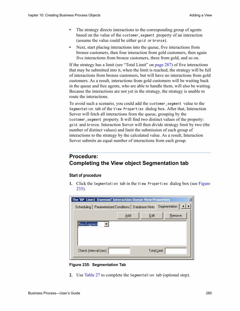
Business Process—User’s Guide 285
hapter 10: Creating Business Process Objects Adding a View
• The strategy directs interactions to the corresponding group of agents based on the value of the customer_segment property of an interaction (assume the value could be either gold or bronze).
• Next, start placing interactions into the queue, five interactions from bronze customers, then four interaction from gold customers, then again five interactions from bronze customers, three from gold, and so on.
If the strategy has a limit (see “Total Limit” on page 287) of five interactions that may be submitted into it, when the limit is reached, the strategy will be full of interactions from bronze customers, but will have no interactions from gold customers. As a result, interactions from gold customers will be waiting back in the queue and free agents, who are able to handle them, will also be waiting. Because the interactions are not yet in the strategy, the strategy is unable to route the interactions.
To avoid such a scenario, you could add the customer_segment value to the Segmentation tab of the View Properties dialog box. After that, Interaction Server will fetch all interactions from the queue, grouping by the customer_segment property. It will find two distinct values of the property: gold and bronze. Interaction Server will then divide strategy limit by two (the number of distinct values) and limit the submission of each group of interactions to the strategy by the calculated value. As a result, Interaction Server submits an equal number of interactions from each group.
Procedure:Completing the View object Segmentation tab
Start of procedure
1. Click the Segmentation tab in the View Properties dialog box (see Figure 235).
Figure 235: Segmentation Tab
2. Use Table 27 to complete the Segmentation tab (optional step).
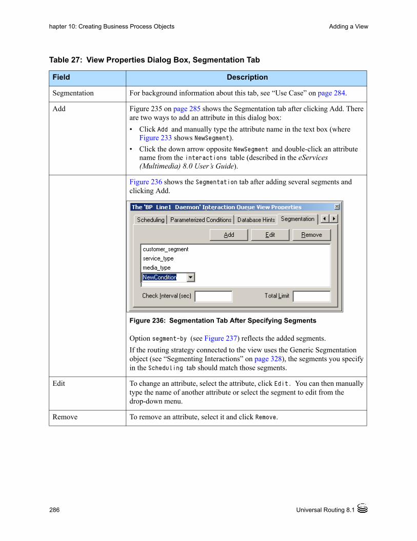
286 Universal Routing 8.1
hapter 10: Creating Business Process Objects Adding a View
Table 27: View Properties Dialog Box, Segmentation Tab
Field Description
Segmentation For background information about this tab, see “Use Case” on page 284.
Add Figure 235 on page 285 shows the Segmentation tab after clicking Add. There are two ways to add an attribute in this dialog box:
• Click Add and manually type the attribute name in the text box (where Figure 233 shows NewSegment).
• Click the down arrow opposite NewSegment and double-click an attribute name from the interactions table (described in the eServices (Multimedia) 8.0 User’s Guide).
Figure 236 shows the Segmentation tab after adding several segments and clicking Add.
Figure 236: Segmentation Tab After Specifying Segments
Option segment-by (see Figure 237) reflects the added segments.
If the routing strategy connected to the view uses the Generic Segmentation object (see “Segmenting Interactions” on page 328), the segments you specify in the Scheduling tab should match those segments.
Edit To change an attribute, select the attribute, click Edit. You can then manually type the name of another attribute or select the segment to edit from the drop-down menu.
Remove To remove an attribute, select it and click Remove.

Business Process—User’s Guide 287
hapter 10: Creating Business Process Objects Adding a View
Notes: If segments are not configured but Total Limit is configured, then Interaction Server calculates a dynamic value. It divides Total Limit by the number of actual types present in the main queue and uses the result to limit the number of each interaction type in the cache queue.
When some segments are specified, Interaction Server adheres to Total Limit. If/when there is room for more interactions to be submitted to the strategy after submitting the specified segments, Interaction Server divides the remaining types up equally.
End of procedure
Setting Numerical Limits for Segments
In some cases, instead of having Interaction Server submit equal numbers of specified interaction segments to a strategy as just described, you might want to set numerical limits for those segments and save that configuration information for reuse with another queue. You can do this in Configuration Manager via the segment-limits section in an Interaction Queue View object in the Scripts folder (see Figure 143 on page 159). As described later, to specify limits for specific segments, you use a combination of values for segmentation attributes separated by a semicolon.
Assume that you wish to configure limits for attributes entered in the Segmentation tab of the View Properties dialog box (see Figure 236 on page 286). After entering the attributes shown in Figure 236, assume the View section in the Annex tab of the corresponding Interaction Queue View Script object appears as shown in Figure 237:
Check Interval (sec) Enter the number of seconds that Interaction Server should use for checking the queue connected to this view. This interval controls how often Interaction Server checks the main queue and adjusts the number of interactions that will be submitted to the strategy according to the Total Limit field. Option segment-check-interval (see Figure 237) reflects the number of seconds.
Total Limit Enter the total number of interactions that can be submitted to the strategy connected to the View object. This option allows you to override the maximum number of interactions that can be submitted to the strategy according to the specified segments. Option segment-total-limit (see Figure 237) reflects Total Limit.
Table 27: View Properties Dialog Box, Segmentation Tab (Continued)
Field Description

288 Universal Routing 8.1
hapter 10: Creating Business Process Objects Adding a View
Figure 237: Interaction Queue View Script Object
Warning! To ensure database integrity, you must define the options that are shown in Figure 237 only in IRD’s Interaction Design window; do not define them in Configuration Manager. The only exception is the segment-limits option described below.
The following procedure describes how to specify limits for different interaction segments, such as work item interactions for different types of services for customers of the Gold, Silver, and Bronze revenue potential.
Procedure:Limiting submission of segments by using Configuration Manager
Start of procedure
1. Open Configuration Manager (see page 237) and go to the Scripts folder for the Tenant.
2. Select the Interaction Queue View Script object that you wish to configure with segment limits.
3. Click the Annex tab.
4. Double-click the View section so it appears under the Annex tab (see Figure 238).

Business Process—User’s Guide 289
hapter 10: Creating Business Process Objects Adding a View
Figure 238: View Section in Annex of View Object Properties Dialog Box
5. Click the button to create a New Section/Option.
6. In the resulting Add Section dialog box, enter segment-limits as the Option Name. In the Option Value field, enter the name of another Script object (to be created) that contains the segment limits configuration. Genesys suggests creating a Script object of type Data Collection for this purpose as described ahead. Figure 239 shows an example completed dialog box.
Figure 239: View Object Edit Option Dialog Box for segment-limits
7. Click OK in the Edit Option dialog box. The option is added to the View section (see Figure 240).
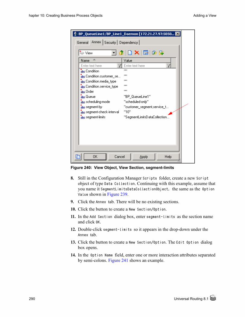
290 Universal Routing 8.1
hapter 10: Creating Business Process Objects Adding a View
Figure 240: View Object, View Section, segment-limits
8. Still in the Configuration Manager Scripts folder, create a new Script object of type Data Collection. Continuing with this example, assume that you name it SegmentLimitsDataCollectionObject, the same as the Option Value shown in Figure 239.
9. Click the Annex tab. There will be no existing sections.
10. Click the button to create a New Section/Option.
11. In the Add Section dialog box, enter segment-limits as the section name and click OK.
12. Double-click segment-limits so it appears in the drop-down under the Annex tab.
13. Click the button to create a New Section/Option. The Edit Option dialog box opens.
14. In the Option Name field, enter one or more interaction attributes separated by semi-colons. Figure 241 shows an example.

Business Process—User’s Guide 291
hapter 10: Creating Business Process Objects Adding a View
Figure 241: Sample Entry in Edit Option Dialog Box
Note: In the above example, there are two semicolons. The second semicolon indicates an unspecified attribute (see Figure 242).
15. In the Option Value field, enter a number to specify a limit for this interaction type and click OK.
16. Repeat steps 13~15 for the next type of interaction that you wish to limit.
17. Click OK.
End of procedure
Figure 242 shows the example Data Collection Script object for segment-limits.
Figure 242: Example Entries for segment-limit option
In this example, the Script object sets limits for submitting three types of interactions to a strategy:
• For segment customer_segment=GOLD, service_type=type1, media_type=workitem (see Figure 148 on page 164), the limit is set to 10.
• For segment customer_segment=SILVER, service_type=type2, media_type=workitem, the limits is set to 20.
Export toConfigurationFile button

292 Universal Routing 8.1
hapter 10: Creating Business Process Objects Adding Workbins
• The first segment sets a limit of 50 for interactions (workitems) of BRONZE customers for which service_type is not set.
Reusing a Configuration
To reuse a segment-limits configuration for use with another queue, click the Export to Configuration File button in the Interaction Queue View Script object (see Figure 242). This opens a Save As dialog box where you can save the information to a file. You can then import the file for a different Interaction Queue View Script object by opening that object, clicking the Import from Configuration File button, and selecting the export file.To import only the segment-limits configuration, click No when the dialog asks whether you wish to overwrite existing data.
View Configuration Caveats
• Do not use attached data for interaction attributes and values.
• Define conditions that process all e-mails in the queue. Any interactions not pulled by a view, remain in the queue.
• Expressions vary between underlying databases, but you can use generic expressions that provide a single interface independent of the underlying database (Oracle, MS SQL, DB2). They are called Translations. Figure 223 on page 273 shows the _time_in_queue translation used in the Condition tab.
Note: See the chapter on interaction properties in the eServices (Multimedia) 8.0 User’s Guide for information about translation functions.
• Logic that appears under the Condition tab is incorporated into the where clause of a SQL select statement and, therefore, has a direct impact on Interaction Server’s performance. In some cases, you may need to create additional indexes in the underlying database to improve performance.
• The order of the view is incorporated in the order clause of the same SQL select statement, and also may impact performance. The default order (by date_received and id) and condition (filter by queue and state) both use an index on the following fields: queue, state, date_received, and id.
Adding WorkbinsFor background information about Workbin objects, see page 33. In order for workbins to be selectable in the IRD Workbin object, they must first be defined as described in this section.

Business Process—User’s Guide 293
hapter 10: Creating Business Process Objects Adding Workbins
Procedure:Adding a Workbin object to a business process
Purpose: To hold interactions for later processing by a particular agent (or Agent Group, Place, Place Group).
Start of procedure
1. Right-click the Workbins folder in the object browser to bring up a menu and select New Workbin (see Figure 243). Alternative methods: Select New Workbin from the Business Process menu. Right-click in the workflow viewer and select New > Workbin.
Figure 243: New Workbin Menu Item
The object browser shows a new Workbin object with a temporary name (see Figure 244).

294 Universal Routing 8.1
hapter 10: Creating Business Process Objects Adding Workbins
Figure 244: New Workbin with Temporary Name
2. Select (slowly double-click) the temporary name and replace it, supplying your own name. Assume that you name it WorkbinAgentA. The browser now appears as shown in Figure 245.
Figure 245: New Workbin Renamed

Business Process—User’s Guide 295
hapter 10: Creating Business Process Objects Adding Workbins
3. Drag the Workbin object into the workflow viewer now or after the next step.
4. Right-click the Workbin object and select Properties from the menu. The Workbin Properties dialog box opens (see Figure 246).
Figure 246: Workbin Properties Dialog Box
5. Use the information in Table 28 to complete the Workbin Properties dialog box:
Table 28: Workbin Properties Dialog Box
Field Description
Script Name In Figure 246, Script Name reflects the name that is entered in the object browser. The queue definition will be saved as a Script of type Workbin in the Configuration Database (see Figure 143 on page 159).
Description Describe the purpose of the Workbin object.
Owner
Agent
Agent Group
Place
Place Group
Indicates whether the Workbin is associated with an agent (Person), Agent Group, Place, or Place Group.
If you change the type of workbin Owner in the Workbin object properties dialog box in the Interaction Design window, you will also need to change it in the Routing Design window in the strategy containing the Workbin routing object. Otherwise, no message will be generated in the IRD Details tab or in the Log tab of the Interaction Design window. This is because Check Integrity (see page 354) was not designed to distinguish the wrong types of existing objects as in the case of selecting the wrong type of Owner in the General tab of the IRD Workbin properties dialog box.
Enabled After activating the strategy as described on page 361, open the Workbin Properties dialog box and select the Enabled check box to specify the workbin state as ready to accept interactions. The default is checked (enabled).
• You can also enable/disable Queue objects the same as any other object in Configuration Manager.
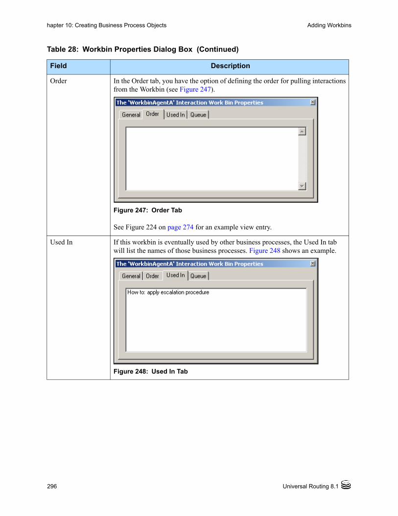
296 Universal Routing 8.1
hapter 10: Creating Business Process Objects Adding Workbins
Order In the Order tab, you have the option of defining the order for pulling interactions from the Workbin (see Figure 247).
Figure 247: Order Tab
See Figure 224 on page 274 for an example view entry.
Used In If this workbin is eventually used by other business processes, the Used In tab will list the names of those business processes. Figure 248 shows an example.
Figure 248: Used In Tab
Table 28: Workbin Properties Dialog Box (Continued)
Field Description

Business Process—User’s Guide 297
hapter 10: Creating Business Process Objects Adding Workbins
6. Select Save from the File menu.
End of procedure
Queue Use the Queue tab (see Figure 249) to associate the workbin with a base queue or when associating multiple workbins with the same queue as described in “Configuring an Escalation Workflow” on page 298.
Figure 249: Queue Tab
You have two queue association options:
• Use The Work Bin’s Private Queue
• Use The Following Queue (enabled when at least one queue exists in the business process)
Use The Work Bin’s Private Queue
When this option is selected, IRD will:
• Create (if no such queue already exists) a private queue.
• Link the workbin to it.
• Hide the private queue from view (you cannot view it in the workflow).
When this option is selected, the next option is disabled.
Use The Following Queue
When this option is selected, the drop-down menu allow you to choose an existing queue. If the workbin was previously linked to a private queue, upon saving the business process, IRD will delete the private queue from the Configuration Database. Later, when you click Locate, IRD highlights the queue within the workflow.
The dropdown menu lists the names of queues that belong to the same business process where the workbin resides. However, if you then move the queue to another business process, IRD shows this queue in the form of <business process>::<queue name>.
Table 28: Workbin Properties Dialog Box (Continued)
Field Description

298 Universal Routing 8.1
hapter 10: Creating Business Process Objects Adding Workbins
Later, when creating routing strategies, any workbins you define in the Interaction Design window will be selectable in the properties dialog box for the Workbin object in the Routing Design window (see Figure 250).
Figure 250: Workbin Properties Dialog Box
• For information about how to attach a view to a workbin, refer back to “Adding a View” on page 267.
• For an example of a workbin with an attached view, see “How To: Apply Escalation Procedure” on page 411.
• For information about connector lines, see page 305.
Configuring an Escalation Workflow
Assume that you have a single workbin and want to submit interactions from the workbin that are over three days old for special processing (escalation). For a single workbin, you could:
• Define a View object for the workbin (see page 267).
• In the Condition tab of the View Properties dialog box, define the following condition to specify the number of seconds in three days:
• age() > 259200
• Draw a Submitter from the view to the escalation strategy.
Now assume you have five different workbins and want to perform the same special processing. You could configure five additional View objects with the same condition and draw five additional Submitters. This “long way” would not only repeats steps, but also would make the workflow picture more complex.
A more efficient way is to lay all the workbins on the same queue and then use the queue in the workflow. This works because a workbin can be associated

Business Process—User’s Guide 299
hapter 10: Creating Business Process Objects Strategy Placeholder Option
with a queue in the Queue tab of the Workbin object as shown in Figure 249 on page 297. Although the queue may be hidden in the workflow picture, it does exist. The steps to implement this shortcut are listed in the following procedure.
Procedure:Configuring an escalation workflow
Start of procedure
1. Define the five Workbin objects as described on page 293.
2. Set the same queue for all the workbins with the Use the Following Queue option described on page 297. The queue will appear in the object browser.
3. Place the Queue object in the workflow.
4. Define a single View object for the queue with the specified escalation condition.
5. Draw a single Submitter line from the view to an escalation strategy. That’s it!
End of procedure
Strategy Placeholder OptionSo far you have created a Queue, View, and Workbin objects. After interactions have been extracted by using a view, you submit them to a routing strategy.
The Independent Objects folder (see Figure 38 on page 63) holds existing routing strategies that are unconnected to a business process. If the routing strategies already exist, you can simply drag and drop them into Strategies folder for the business process.
Note: After a routing strategy has been used in a business process, you can find it under that business process and reuse it, if necessary.
If the required routing strategies do not exist yet, you have two options:
1. Create a strategy placeholder and postpone the actual routing strategy configuration (which can be more time-consuming than creating queues and views) to a later time. If this option is used, you could continue creating the remaining queues and views that are required by the business process.
2. The second option is to create the routing strategy immediately, as described in “Creating Strategies” on page 323.

300 Universal Routing 8.1
hapter 10: Creating Business Process Objects Strategy Placeholder Option
The following instructions explain how to create a strategy placeholder in a business process. See page 323 if you wish to create the routing strategy at this time.
Note: You must use the Routing Design window to create subroutines; you cannot create them in the Interaction Design window.
Procedure:Creating strategy placeholders
Purpose: To create an empty Strategy Script object as a placeholder in a business process, which can be configured later.
Start of procedure
1. With the applicable business process open and selected (see “Switching to another business process” on page 252), click the Business Process menu and select New Strategy. The New dialog box opens in the Routing Design window (see Figure 251 on page 300).
Figure 251: Dialog Box for Creating New Strategy
2. Name and describe the strategy and click OK. The Routing Design window opens with the name of the strategy in the title bar (see Figure 252).

Business Process—User’s Guide 301
hapter 10: Creating Business Process Objects Strategy Placeholder Option
Figure 252: Routing Design Window
3. Click the File menu and select Save. The Save dialog box opens (see Figure 253 on page 301).
Figure 253: Save Dialog Box
4. Keep the path for the graphical portion (see page 172) of the strategy (RBN File Path) or click the browse button (...) to select a new path.
5. Optional step. Click in the box under CME Script Folder and double-click a subfolder under the Scripts folder.
6. Click OK in the Save dialog box.
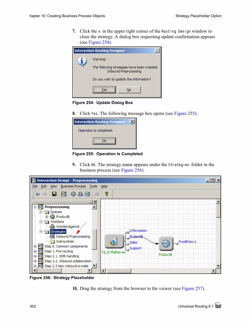
302 Universal Routing 8.1
hapter 10: Creating Business Process Objects Strategy Placeholder Option
7. Click the x in the upper right corner of the Routing Design window to close the strategy. A dialog box requesting update confirmation appears (see Figure 254).
Figure 254: Update Dialog Box
8. Click Yes. The following message box opens (see Figure 255).
Figure 255: Operation Is Completed
9. Click OK. The strategy name appears under the Strategies folder in the business process (see Figure 256).
Figure 256: Strategy Placeholder
10. Drag the strategy from the browser to the viewer (see Figure 257).
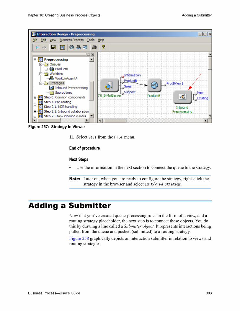
Business Process—User’s Guide 303
hapter 10: Creating Business Process Objects Adding a Submitter
Figure 257: Strategy in Viewer
11. Select Save from the File menu.
End of procedure
Next Steps
• Use the information in the next section to connect the queue to the strategy.
Note: Later on, when you are ready to configure the strategy, right-click the strategy in the browser and select Edit/View Strategy.
Adding a SubmitterNow that you’ve created queue-processing rules in the form of a view, and a routing strategy placeholder, the next step is to connect these objects. You do this by drawing a line called a Submitter object. It represents interactions being pulled from the queue and pushed (submitted) to a routing strategy.
Figure 258 graphically depicts an interaction submitter in relation to views and routing strategies.

304 Universal Routing 8.1
hapter 10: Creating Business Process Objects Adding a Submitter
Figure 258: Submitter Actions
Procedure:Creating a Submitter object
Purpose: To connect a view extracting interactions from a queue to a routing strategy where the interaction can have specialized processing tasks applied.
Start of procedure
1. Draw a submitter (see “Submitters” on page 39) from the View object to the Strategy object. This tells Interaction Server to submit interactions extracted from the queue using the view to the strategy (see Figure 259).
Figure 259: Submitter Object
Queue
View
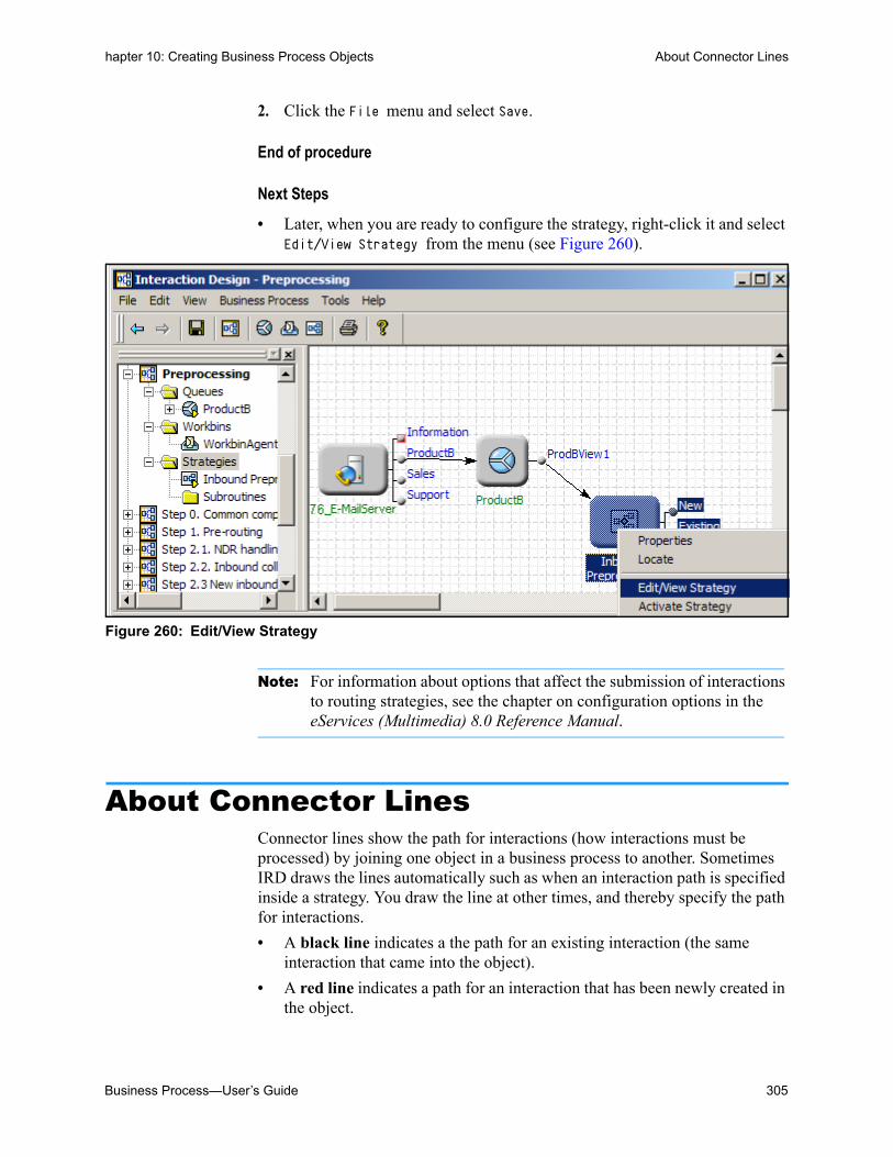
Business Process—User’s Guide 305
hapter 10: Creating Business Process Objects About Connector Lines
2. Click the File menu and select Save.
End of procedure
Next Steps
• Later, when you are ready to configure the strategy, right-click it and select Edit/View Strategy from the menu (see Figure 260).
Figure 260: Edit/View Strategy
Note: For information about options that affect the submission of interactions to routing strategies, see the chapter on configuration options in the eServices (Multimedia) 8.0 Reference Manual.
About Connector LinesConnector lines show the path for interactions (how interactions must be processed) by joining one object in a business process to another. Sometimes IRD draws the lines automatically such as when an interaction path is specified inside a strategy. You draw the line at other times, and thereby specify the path for interactions.
• A black line indicates a the path for an existing interaction (the same interaction that came into the object).
• A red line indicates a path for an interaction that has been newly created in the object.

306 Universal Routing 8.1
hapter 10: Creating Business Process Objects Exporting and Importing a Business Process
Depending on the type of object, connectors may be placed automatically, or you may need to place them manually.
• To add a connector, hover your cursor over the object where the connector should start. When the cursor becomes a pointing hand, hold down the left mouse button and move the cursor to the object where the connector should end.
• To delete a connector, select it, and then press the Delete key; or, right-click the connector, and then select Disconnect and/or Hide from the shortcut menu.
Note: You cannot delete a connector that has been automatically placed, or delete the object to which it connects. Instead, you must edit the object that generated the automatically placed connector, so that it no longer contains that particular strategy-linked node. In the figure above, to remove the Stop interaction node and its connector, you must edit the Forward e-mail processing strategy.
• To reshape a connector, select it, place the cursor over one of the red x's that mark the ends of the lines and the control points along the line's Bezier curve, and drag the x to a new location.
Removing an Object
To remove an object from a business process: in the object browser, drag it from the business process folder and drop it into the Independent Objects folder.
Exporting and Importing a Business Process
Notes: In addition to exporting and importing business processes in the Interaction Design window as described in this section, you can also use IRD’s Export solution and Import solution views to:
• Export/import objects between strategies.• Export strategies using archive, native, open, and text format.• Export a group of strategies or subroutines.
For more information about these views, see the chapter on routing strategies, Migrating Strategies and Other Objects section, in the Universal Routing 8.1 Reference Manual.

Business Process—User’s Guide 307
hapter 10: Creating Business Process Objects Exporting and Importing a Business Process
This section describes how to export and import business processes. Having the ability to export and import business processes allows you to:
• Store the information contained in a business process; for the purpose of creating a backup copy, for example.
• Easily move business processes located in your Test environment to your Production environment.
• Share or consult on workflow design with a co-worker.
• Automatically create all the required Configuration Layer objects during the export process and write them to a Configuration Database during the import process.
IRD simplifies the operation by letting you export/import multiple business processes at once. You will most likely use this feature since one business process may depend on processing that occurs in another business process or use objects that originate outside of itself.
Procedure:Exporting a business process
Perform the following steps to export a business process. If the business process is already open, skip to step 5.
Start of procedure
1. Log in as described in “Opening IRD” on page 57.
2. Click the Interaction Design shortcut bar on the left.
3. Click the Business Processes icon. Existing business processes are listed for selection as shown in Figure 35 on page 60.
4. Double-click any business process to open the Interaction Design window.
5. Click the File menu and select Export. The Export dialog box opens (see Figure 261 on page 308).

308 Universal Routing 8.1
hapter 10: Creating Business Process Objects Exporting and Importing a Business Process
Figure 261: Export Dialog Box
6. In the Export dialog box, select the business processes that you wish to export so they are highlighted. To select individual business processes, hold down the Ctrl key while
you select. To group-select, hold down the Shift key while you select.
Note: Media servers (see page 39) are not included in IRD’s export/import process.
7. Under Short Comments in the Export dialog box, enter any comments (optional).
8. Click the Browse button. The Choose File Name dialog box opens (see Figure 262).

Business Process—User’s Guide 309
hapter 10: Creating Business Process Objects Exporting and Importing a Business Process
Figure 262: Choose File Name Dialog Box
9. If not already selected, browse to/create the folder to hold the exported business process.
10. Enter the file name for the exported business process.
11. Click Save in the Choose File Name dialog box. The Export dialog box reflects your entries. Figure 263 shows an example completed dialog box.
Figure 263: Export Dialog Box
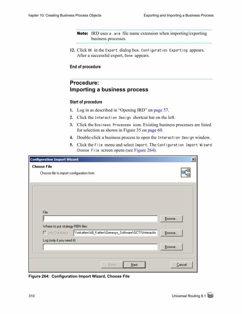
310 Universal Routing 8.1
hapter 10: Creating Business Process Objects Exporting and Importing a Business Process
Note: IRD uses a .wie file name extension when importing/exporting business processes.
12. Click OK in the Export dialog box. Configuration Exporting appears. After a successful export, Done appears.
End of procedure
Procedure:Importing a business process
Start of procedure
1. Log in as described in “Opening IRD” on page 57.
2. Click the Interaction Design shortcut bar on the left.
3. Click the Business Processes icon. Existing business processes are listed for selection as shown in Figure 35 on page 60.
4. Double-click a business process to open the Interaction Design window.
5. Click the File menu and select Import. The Configuration Import Wizard Choose File screen opens (see Figure 264).
Figure 264: Configuration Import Wizard, Choose File
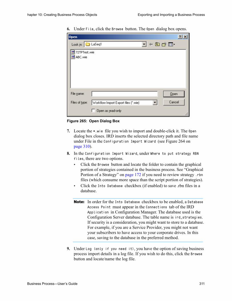
Business Process—User’s Guide 311
hapter 10: Creating Business Process Objects Exporting and Importing a Business Process
6. Under File, click the Browse button. The Open dialog box opens.
Figure 265: Open Dialog Box
7. Locate the *.wie file you wish to import and double-click it. The Open dialog box closes. IRD inserts the selected directory path and file name under File in the Configuration Import Wizard (see Figure 264 on page 310).
8. In the Configuration Import Wizard, under Where to put strategy RBN files, there are two options. Click the Browse button and locate the folder to contain the graphical
portion of strategies contained in the business process. See “Graphical Portion of a Strategy” on page 172 if you need to review strategy .rbn files (which consume more space than the script portion of strategies).
Click the Into Database checkbox (if enabled) to save .rbn files in a database.
Note: In order for the Into Database checkbox to be enabled, a Database Access Point must appear in the Connections tab of the IRD Application in Configuration Manager. The database used is the Configuration Server database. The table name is ird_strategies. If security is a consideration, you might want to store to a database. For example, if you are a Service Provider, you might not want your subscribers to have access to your corporate drives. In this case, saving to the database in the preferred method.
9. Under Log (only if you need it), you have the option of saving business process import details in a log file. If you wish to do this, click the Browse button and locate/name the log file.

312 Universal Routing 8.1
hapter 10: Creating Business Process Objects Exporting and Importing a Business Process
10. Click Next. The Configuration Wizard Confirm Importing screen opens (see Figure 266 on page 312).
Figure 266: Configuration Import Wizard, Confirm Importing
11. If satisfied with your entries, click Import; otherwise click Back to return to the Configuration Import Wizard Choose File screen.
12. Respond to any messages that might appear.
End of procedure
Problems During Importing
If an import request encounters problems, IRD lists the problems and possible workarounds. You can:
• Choose the workaround for each problem.
• Cancel the import operation.
Figure 267 shows an example dialog box when objects to be imported already exist in the Configuration Database.

Business Process—User’s Guide 313
hapter 10: Creating Business Process Objects Exporting and Importing a Business Process
Figure 267: The Following Problems Encountered Dialog Box
Note: Choosing particular workaround might trigger another problem. For example, if a strategy already exists, choosing to overwrite the strategy might cause a problem if the .rbn file that is associated with the strategy already exists in the specified location. In such cases, IRD displays another dialog box.
If you click Cancel Import, the dialog box appears as shown in Figure 268.

314 Universal Routing 8.1
hapter 10: Creating Business Process Objects Exporting and Importing a Business Process
Figure 268: Canceling an Import Operation
Problem types and workarounds are listed here.
Problem: Object that is to be imported already exists in the Configuration Database.
Applicable to objects of the same type (queues, views, strategies, and so on). IRD offers the following workarounds:
• Do not import the object
• Overwrite existing object
Exceptions: For business processes, the only allowed workaround is merging. Since a business process object keeps a list of the objects that belong to it, merging combines that list of objects with the objects belonging to the business process being imported.
Problem: The name of the object being imported conflicts with an existing object.
Applicable to objects of different types (business process, queue, view, strategy, workbin) that are of the same Configuration Manger object type (Script). For example, a conflict is created when you attempt to import a

Business Process—User’s Guide 315
hapter 10: Creating Business Process Objects Distribution of Load Between Multiple Interactions Servers
queue Script object having the same name as an existing strategy Script object. IRD offers the following workaround:
• Do not import the object.
Exceptions: If importing business process conflicts with an existing object (Script object of different type), IRD considers the problem to be severe and the import operation always aborts.
Problem: The .rbn file of the imported strategy already exists in the specified location.
Applicable to strategies. IRD offers the following workarounds:
• Put the file into alternative location. The alternative location is an automatically created subfolder in the location you specified on import startup.
• Overwrite existing file.
Exceptions: None.
Automatic Decisions
IRD’s import utility automatically makes/logs the following decisions:
• When the attempt to import a submitter (see page 39) conflicts with either an existing submitter or a Script object of a different type, the imported submitter takes a new name.
• When an association between a view (see page 28) and strategy (see page 30) already exists (i.e., there is a submitter that connects the view and the strategy), IRD does not import the submitter.
• When a parent object is not imported (such as a queue with a view child object or a view with a submitter child object) according to the chosen workaround), the child object is also not imported.
Distribution of Load Between Multiple Interactions Servers
Overview
Starting with release 8.1.3, a Business Processes can be assigned to different Accounts in order to distribute the load between multiple Interactions Serv-ers within one tenant. By default, a single Interaction Server within a tenant will run all Business Processes that belong to this tenant. For large custom-ers with high interaction volume requirements, the ability of multiple Inter-

316 Universal Routing 8.1
hapter 10: Creating Business Process Objects Distribution of Load Between Multiple Interactions Servers
action Servers to process interactions within specific tenants can be used to achieve much better performance.
Creating an Account
An Account is a set of Business Processes (with all related sub-objects: queues, views, workbins, submitters, strategies) that a single Interaction Server works with. The Business Process main menu of the Interaction Design window has a dedicated selection that can be used to create a new Account. See Figure 269. There is also a corresponding icon on the tool bar of the Interac-tion Design window that can be used. An existing Accounts can be deleted using the regular Delete menu selection.
Figure 269: New Account

Business Process—User’s Guide 317
hapter 10: Creating Business Process Objects Distribution of Load Between Multiple Interactions Servers
In the Browser part of the Interaction Design window, each Account is pre-sented as a folder. See Figure 270.
Figure 270: Account Folder
The Account object properties dialog box may be viewed by right-clicking the Account folder, and selecting Properties. See Figure 271.
Figure 271: Account Properties
Every new Account created in the Interaction Design window is presented in the configuration by special Access Group object. These Access Group objects are created on the Environment level in the Multitenant configura-tion environment or on the Resources level when working in a Single-Ten-
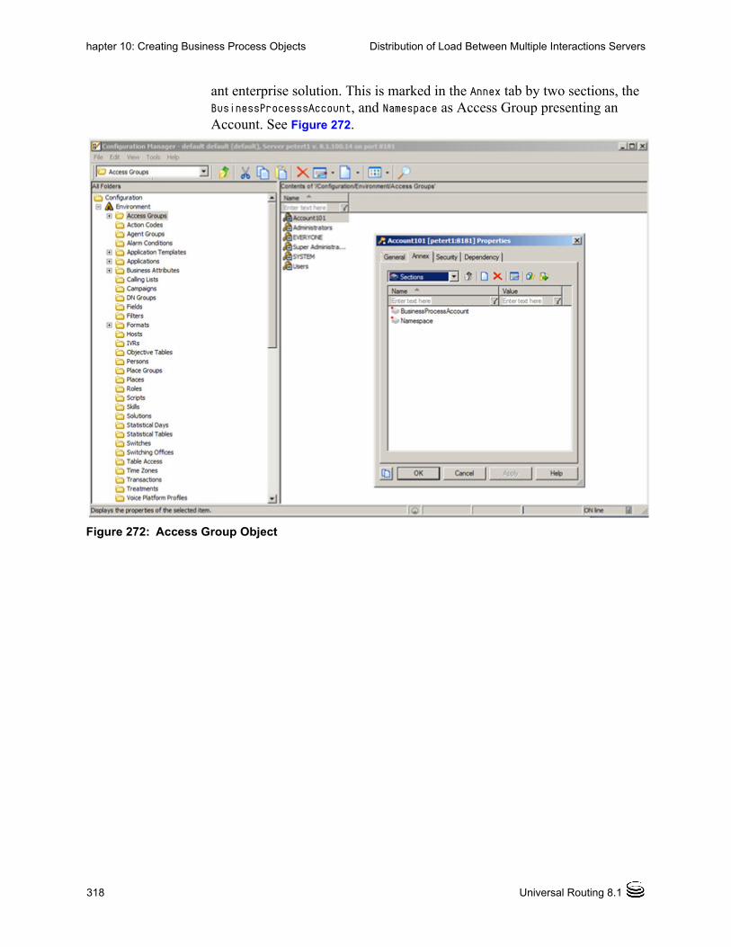
318 Universal Routing 8.1
hapter 10: Creating Business Process Objects Distribution of Load Between Multiple Interactions Servers
ant enterprise solution. This is marked in the Annex tab by two sections, the BusinessProcesssAccount, and Namespace as Access Group presenting an Account. See Figure 272.
Figure 272: Access Group Object

Business Process—User’s Guide 319
hapter 10: Creating Business Process Objects Distribution of Load Between Multiple Interactions Servers
The Namespace section refers to the name of that particular Account. SeeFigure 273.
Figure 273: Namespace Section
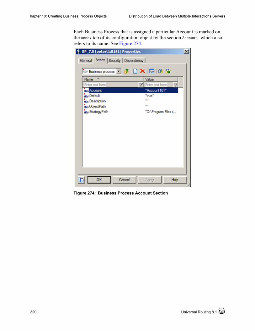
320 Universal Routing 8.1
hapter 10: Creating Business Process Objects Distribution of Load Between Multiple Interactions Servers
Each Business Process that is assigned a particular Account is marked on the Annex tab of its configuration object by the section Account, which also refers to its name. See Figure 274.
Figure 274: Business Process Account Section
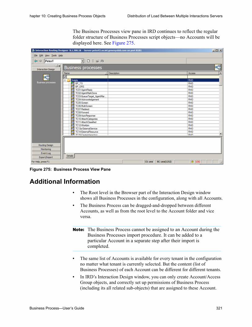
Business Process—User’s Guide 321
hapter 10: Creating Business Process Objects Distribution of Load Between Multiple Interactions Servers
The Business Processes view pane in IRD continues to reflect the regular folder structure of Business Processes script objects—no Accounts will be displayed here. See Figure 275.
Figure 275: Business Process View Pane
Additional Information
• The Root level in the Browser part of the Interaction Design window shows all Business Processes in the configuration, along with all Accounts.
• The Business Process can be dragged-and-dropped between different Accounts, as well as from the root level to the Account folder and vice versa.
• The same list of Accounts is available for every tenant in the configuration no matter what tenant is currently selected. But the content (list of Business Processes) of each Account can be different for different tenants.
• In IRD’s Interaction Design window, you can only create Account/Access Group objects, and correctly set up permissions of Business Process (including its all related sub-objects) that are assigned to these Account.
Note: The Business Process cannot be assigned to an Account during the Business Processes import procedure. It can be added to a particular Account in a separate step after their import is completed.

322 Universal Routing 8.1
hapter 10: Creating Business Process Objects Distribution of Load Between Multiple Interactions Servers
Any other functionality (association of specific Interaction Server with a particular Account, creation of Person objects for Interaction Server to work on behalf of, and so on) will need to be done outside of IRD. For detailed information please refer to the related eServices documentation.
Business Process—User’s Guide 323
Chapter
11 Creating StrategiesThis chapter provides step-by-step instructions for creating a routing strategy. It covers the following topics: Preparation, page 323 Sample Strategy, page 324 Summary of Strategy-Creation Process, page 324 Creating a New Strategy, page 326 Segmenting Interactions, page 328 Writing Interaction Data to Variables, page 340 Determining Interaction Status, page 347 Sending interactions to Queues, page 350 Compiling, page 353 Checking Database Integrity, page 354 Adding a Strategy to a Business Process, page 356 Editing/Viewing Strategies, page 357 Deleting Strategies, page 359
PreparationAt this point, this guide assumes you have already:
• Started the business process with its queues and views (see “Creating Business Process Objects” on page 247).
• Created Knowledge Manager objects so that Categories, Standard Responses, and Field Codes will be selectable in the associated IRD object properties dialog boxes (see “Creating Knowledge Manager Objects” on page 223).

324 Universal Routing 8.1
Chapter 11: Creating Strategies Sample Strategy
• Created Configuration Manager objects so that Persons, Agents, Agent Groups, Place, Place Groups, and Business Attributes will be selectable in IRD object properties dialog boxes (see “Creating Configuration Manager Objects” on page 237).
If this preparation is complete, the process of creating routing strategies will not be interrupted by the need to create additional configuration objects.
Sample StrategyThis chapter demonstrates how to create the strategy shown in Figure 276.
Figure 276: Inbound E-mail Preprocessing Strategy
This same strategy is contained in the business process “Step 1. Pre-Routing” on page 391 as part of the Genesys-supplied Interaction Workflow Samples component as described in “About the Samples” on page 370.
Summary of Strategy-Creation ProcessTable 29 summarizes the process of creating the routing strategy shown in Figure 276. For complete, step-by-step instructions on creating routing strategies in general, see the Universal Routing 8.1 Interaction Routing Designer Help.

Business Process—User’s Guide 325
Chapter 11: Creating Strategies Summary of Strategy-Creation Process
Table 29: Steps for Creating the Inbound Preprocessing Strategy
Objective Related Procedures
1. To open the Routing Design window where you create a new strategy.
• “Creating a new strategy from the IRD main window” on page 326.
2. To cause incoming interactions to take difference paths in the strategy based on media type, processing status, and so on.
• “Placing the Generic Segmentation object and opening Expression Builder” on page 328.
• “Segmenting Based on an Expression” on page 331.
• “Sending Segmented Interactions to Queues” on page 337.
3. Writing interaction data to variables for later use in a business process.
• “Defining Variables” on page 341.
• “Assigning a value to a variable from Interaction Data” on page 342.
• “Assigning a value to a variable using a function” on page 345.
4. Determining interaction status (new inbound, already processed by Genesys, and so on)
• “Using the Generic Segmentation object to determine interaction status” on page 347.
5. Sending interactions to queues. • “Sending interactions to queues from the Generic Segmentation object” on page 350.
6. Compiling a routing strategy. • “Compiling a routing strategy” on page 353.
7. Checking that objects contained in a strategy are found in the Configuration Database.
• “Using Check Integrity” on page 354.
8. Adding a strategy to a folder in the Interaction Design window prior to using the strategy in a business process.
• “Adding a strategy in the Independent Objects folder to a business process” on page 356.
9. Re-using a strategy. • “Re-using a strategy already contained in a business process” on page 356
10.Viewing and editing strategies. • “Editing/viewing a strategy from the Interaction Design window” on page 357
• “Viewing a strategy from the IRD main window” on page 359
• “Deleting strategies from the Interaction Design window” on page 359
• “Deleting strategies from the Strategies List pane” on page 360

326 Universal Routing 8.1
Chapter 11: Creating Strategies Creating a New Strategy
Creating a New StrategyThe very first steps in creating a new strategy depends on your starting location within IRD and whether a strategy placeholder exists in the business process (see page 299).
Methods
After logging into IRD (see page 58), one of the options below will apply:
• If you are in the IRD main window (see Figure 34 on page 59), continue with step 1 below.
• If the business process is already open in the Interaction Design window, right-click the Strategies folder in the object browser and select New Strategy.
• If the business process is already open in the Interaction Design window, and you previously created a strategy placeholder, right-click the strategy and select Edit/View Strategy from the menu (see Figure 260 on page 305). The strategy appears in the Routing Design window as shown in Figure 278. To create the sample strategy shown in Figure 276 on page 324, continue with “Segmenting Interactions” on page 328.
Procedure:Creating a new strategy from the IRD main window
While this procedure describes how to create an inbound interaction preprocessing strategy shown in Figure 114 on page 132, the steps apply to creating a routing strategy in general.
Start of procedure
1. In the IRD main window (see Figure 34 on page 59), click the Strategies button.
Note: To enable New from the File menu, a folder or subfolder in the list pane must already be selected.
2. If a folder is already selected, from the File menu, click New. You can also right-click any folder on the list pane and select New. The New dialog box opens. Figure 277 on page 327 shows an example completed dialog box.

Business Process—User’s Guide 327
Chapter 11: Creating Strategies Creating a New Strategy
Figure 277: New Dialog Box After Naming and Describing Strategy
3. After clicking OK, the Routing Design window opens with an Entry object (see Figure 278).
Figure 278: Routing Design Window Before Strategy Configuration
End of procedure
Next Steps
• Placing, configuring, and connecting IRD objects to define strategy processing.

328 Universal Routing 8.1
Chapter 11: Creating Strategies Segmenting Interactions
Segmenting InteractionsAfter the Entry object in Figure 276 on page 324, the next object is a Generic Segmentation object.
Procedure:Placing the Generic Segmentation object and opening Expression Builder
Purpose: To open the dialog box where you create an expression to causes interactions to take different paths in the strategy.
Start of procedure
1. In the Routing Design window, click the icon for Segmentation objects (see Figure 279).
Figure 279: Segmentation Objects Icon
Generic Segmentation Object

Business Process—User’s Guide 329
Chapter 11: Creating Strategies Segmenting Interactions
Note: See “Segmentation Objects” on page 208. For detailed information about all Segmentation objects, see the section on IRD objects in Universal Routing 8.1 Reference Manual.
2. Click the button for the Generic Segmentation object. Then click inside the Routing Design window at the location where you want to place the object. The Routing Design window now appears as shown in Figure 280.
Figure 280: Segmentation Object After Entry Object
3. Double-click the Segmentation object to opens its properties dialog box.
4. Click the button for creating a new entry. The properties dialog now appears as shown in Figure 281.
Figure 281: Generic Segmentation Properties Dialog Box: Starting
5. Click under Expression. A down arrow appears (see Figure 282).
New Entry Button
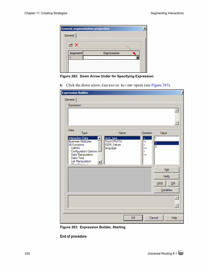
330 Universal Routing 8.1
Chapter 11: Creating Strategies Segmenting Interactions
Figure 282: Down Arrow Under for Specifying Expression
6. Click the down arrow. Expression Builder opens (see Figure 283).
Figure 283: Expression Builder, Starting
End of procedure

Business Process—User’s Guide 331
Chapter 11: Creating Strategies Segmenting Interactions
Procedure:Segmenting Based on an Expression
Purpose: To define an expression in the Expression Builder dialog box where the true/false value of the expression will determine each segment (each path) in the routing strategy.
The first expression will determine whether the interaction has contains the InboundCollaborationReply Interaction Subtype (see Figure 148 on page 164). Use the instructions below to create this expression.
Start of procedure
1. In Expression Builder (see Figure 283 on page 330), under Type, click All Functions.
2. Under Name, scroll down and click Business Data. Expression Builder adds a new panel where you enter parameters and values (see Figure 284).
Figure 284: Expression Builder, Parameter and Value Fields

332 Universal Routing 8.1
Chapter 11: Creating Strategies Segmenting Interactions
3. Leave the equal sign selected.
4. Click in the row under Value to display a down arrow.
5. Click the down arrow to bring up the Key dialog box (see Figure 285).
Figure 285: Key Dialog Box, Business Data Type
6. Click the Value down arrow in Figure 285 and select InteractionSubtype (see Figure 286).
Figure 286: Key Dialog Box, Interaction Subtype Value
7. Close the Key dialog box. The row under the Value area in Expression Builder now appears as shown in Figure 287.

Business Process—User’s Guide 333
Chapter 11: Creating Strategies Segmenting Interactions
Figure 287: Expression Builder Parameter Value Area
8. Under Operator in Expression Builder, select the equal sign (=).
9. Click under Value and enter: CollaborationReply (see Figure 148 on page 164).
Note: Collaboration Reply is the display name; the internal name in the Configuration Database is CollaborationReply. You can see this in Configuration Manager when you right-click an Interaction Subtype and select Properties.
10. Click the Add button. Expression Builder now appears as shown in Figure 288.

334 Universal Routing 8.1
Chapter 11: Creating Strategies Segmenting Interactions
Figure 288: Expression Builder With Expression Created
11. Click the Verify button.
The expression turns green indicating it is successfully verified. The following message appears in the lower pane: The expression is successfully verified.
12. Click OK to close Expression Builder. The Generic Segmentation Properties dialog box appears as shown in Figure 289 (entire expression not shown).

Business Process—User’s Guide 335
Chapter 11: Creating Strategies Segmenting Interactions
Figure 289: Expression in Generic Segmentation Properties Dialog Box
In Segment 1 in Figure 289, the entire expression reads:
BusinessData['InteractionSubtype'] = 'CollaborationReply'
The expression instructs URS to use the BusinessData function (documented in the Universal Routing 8.1 Reference Manual) with a Business Data parameter of type InteractionSubtype with a value of CollaborationReply.
13. Construct the next row in the Generic Segmentation Properties dialog box (Figure 289) as follows: Click the button to add an item (see Figure 281 on page 329). Repeat the above steps, but substitute NDR for the Value in Step 14. When through in the Generic Segmentation Properties dialog box,
you will have created two expressions (see Figure 290).
Figure 290: Expressions in Generic Segmentation Properties Dialog Box

336 Universal Routing 8.1
Chapter 11: Creating Strategies Segmenting Interactions
URS will use the first expression to determine whether an interaction has already been processed by Genesys and now contains the CollaborationReply Interaction Subtype. If true, it is an interaction resulting from two agents collaborating. The interaction contains the draft reply being sent back to the original agent from the collaborating agent.
URS will use the second expression to determine whether an interaction has already been processed by Genesys and now contains an NDR Interaction Subtype. If true, it is an interaction where no destination can be reached (NDR). It needs to take a different path in the strategy than a CollaborationReply interaction.
14. Close the Generic Segmentation Properties dialog box,. The Routing Design window still appears as shown in Figure 280 on page 329.
15. Connect the Entry object to the Generic Segmentation object as follows: Click and hold on the bottom port of the Entry object. Drag the cursor to the green input port of the Generic Segmentation
object and release. The objects now appear as shown in Figure 291.
Figure 291: Entry Object Connected to Generic Segmentation Object
In Figure 291, note that the Generic Segmentation object has two green side ports. The first port corresponds to the first expression in Figure 290 on
page 335. The second port corresponds to the second expression in Figure 290 on
page 335.
Each port will have different processing associated with it. This means: If an interaction meets the first condition, it goes out the first port for
inbound collaboration replies.

Business Process—User’s Guide 337
Chapter 11: Creating Strategies Segmenting Interactions
If an interaction meets the second condition, it goes out the second port for interactions where no destination can be reached.
16. Click the File menu and select Save.
End of procedure
Next Steps
• Sending segmented interactions to queues.
The next stage in constructing the routing strategy shown in Figure 276 on page 324 consists of connecting each of the two side ports (see Figure 291) in the Generic Segmentation object to different Queue Interaction objects (each specifying a different queue).
Procedure:Sending Segmented Interactions to Queues
Purpose: Once segmented interactions are placed in queues, you can send them to different objects within the strategy for additional processing.
Start of procedure
1. In the Routing Design window, click the icon for Routing objects (see Figure 292).
Figure 292: Icon For Multimedia Objects
Routing Objects
Queue Interaction Object

338 Universal Routing 8.1
Chapter 11: Creating Strategies Segmenting Interactions
2. Click the button for the Queue Interaction object (see Figure 292). Then click inside the Routing Design window at the location where you want to place the object. The Routing Design window now appears as shown in Figure 293.
Figure 293: Routing Design window, Queue Interaction Object Placed
3. Double-click the Queue Interaction object to opens its properties dialog box (see Figure 293).
4. Click the down arrow to drop down a menu where you can select an interaction queue by expanding existing business processes (see Figure 294).
Figure 294: Queue Interaction Properties Dialog Box

Business Process—User’s Guide 339
Chapter 11: Creating Strategies Segmenting Interactions
Note: If you followed the “Order of Configuration” on page 217, the required queue will be available for selection.
5. Double-click a queue and click OK. The Queue Interaction Properties dialog box appears as shown in Figure 295.
Figure 295: Queue Interaction Object, Queue Selected
Note: The queue could be one used by another business process if creating a number of smaller, less complex business processes (see page 200). Or the queue could be one in a different functional area of this business process if creating a larger, more complex business process.
6. Click OK in the Queue Interaction Properties dialog box.
7. Draw a connector line from the first side port of the Generic Segmentation object in Figure 293 on page 338 to the yellow input port of the Queue Interaction object. This indicates that inbound collaboration reply interactions should be sent to this queue.

340 Universal Routing 8.1
Chapter 11: Creating Strategies Writing Interaction Data to Variables
8. Follow steps 1~6 to create a second Queue Interaction object to handle No Destination Reached (NDR) interactions, but this time select a different queue in Figure 294 on page 338.
9. Draw a connector line from the second side port of the Generic Segmentation object in Figure 293 on page 338 to the yellow input port of the Queue Interaction object for inbound NDR interactions.
The routing strategy now appears as shown in Figure 296.
Figure 296: Routing Design Window, Segmenting to Different Queues
Note: If the strategy isn’t commented as shown above, click the Tools menu in the IRD main window and select Routing Design Options. The Routing Options dialog box opens (see Figure 127 on page 142). Put an X in the checkboxes opposite Show Conditions On Graph and Show Description of Objects On Graph.
10. Save the strategy.
End of procedure
Note: In addition to showing conditions and descriptions, you can also insert comments. Right-click inside the strategy and select Insert Comment from the context menu. In the resulting text box, enter your comments.
Writing Interaction Data to VariablesSo far we have configured the sample strategy shown in Figure 276 on page 324 to handle collaboration reply and NDR interactions. The next objects to be configured determine whether an incoming interaction has an inbound processing failed status. To do this, the strategy will:

Business Process—User’s Guide 341
Chapter 11: Creating Strategies Writing Interaction Data to Variables
Write the contents of custom interaction keys (GEM_Failure and GEM_FailureMsg) to variables. The assumption is that these keys were previously added to the interaction attributes via the custom* fields in the interactions table as described in the chapter on interaction properties in the eServices (Multimedia) 8.0 User’s Guide.
The strategy then checks those variables and routes based on the true/false value of an expression.
• If the interaction does have inbound processing failed status, it will be sent to a queue for these types of interactions.
• If the interaction does not have inbound processing failed status, the interaction will be sent to a different queue for new inbound interaction processing.
Procedure:Defining Variables
Purpose: To define variables to hold the content of the GEM_Failure and GEM_FailureMsg attached data keys.
Start of procedure
1. In the Routing Design window, click the button for defining variables (see Figure 297).
Figure 297: Variables Button
2. In the resulting Variable List Properties dialog box, define EPF_flag and EPF_value string variables. The dialog box appears as shown in Figure 298.

342 Universal Routing 8.1
Chapter 11: Creating Strategies Writing Interaction Data to Variables
Figure 298: Variable List Properties Dialog Box
3. Click OK in the Variable List Properties dialog box.
End of procedure
Next Steps
• Assigning values to variables.
Now that the variables exist, use the Multi-Assign object to assign values.
Procedure:Assigning a value to a variable from Interaction Data
Start of procedure
1. In the Routing Design window, click the button for Miscellaneous objects (see Figure 299).

Business Process—User’s Guide 343
Chapter 11: Creating Strategies Writing Interaction Data to Variables
Figure 299: Miscellaneous Objects
2. Click the button for the Multi-Assign object (see Figure 106 on page 126). Then click inside the empty Routing Design window at the location where you want to place the object.
3. Double-click the Multi-Assign object to opens its properties dialog box.
4. Click the button to add an item in the Multi-Assign Properties dialog box (see Figure 300).
Figure 300: Multi-Assign Properties Dialog Box
5. Click in the Name field and select the EPF_flag variable.
6. Click under Expression. A down arrow appears (see Figure 301).
Figure 301: Expression Down Arrow
Miscellaneous Objects

344 Universal Routing 8.1
Chapter 11: Creating Strategies Writing Interaction Data to Variables
7. Click the down arrow to open the Assign Properties dialog box (see Figure 301) where you can assign a value to the variable.
8. Under Type, select Interaction Data.
9. Under Name, select GEM_Failure.
Note: The assumption is that this key is contained in the interaction and was previously defined in IRD as Interaction Data (see page 119).
10. Click Add followed by Verify. The Assign Properties dialog box appears as shown in Figure 302.
Figure 302: Assign Properties Dialog Box, Expression Verified
The content of the GEM_Failure key in the interaction will be written to the EPF_flag variable.

Business Process—User’s Guide 345
Chapter 11: Creating Strategies Writing Interaction Data to Variables
11. Click OK in the Assign Properties dialog box.
End of procedure
Procedure:Assigning a value to a variable using a function
Start of procedure
1. Click the button to add an item in the Multi Assign Properties dialog box (see Figure 300 on page 343).
2. Click in the Name field and select the EPF_value variable.
3. Click under Expression in the Multi-Assign Properties dialog box. A down arrow appears similar to Figure 301 on page 343.
4. Click the down arrow to open the Assign Properties dialog box (see Figure 302 on page 344).
5. Under Type, select All Functions.
6. Under Name, select the Update function.
7. Click the down arrow under Value in the Assign Properties dialog box. The Key dialog box opens.
8. Click the Type arrow and select the EPF_flag variable (see Figure 303)
Figure 303: Key Dialog Box
9. Click OK.
10. Back in the Assign Properties dialog box, click Add followed by Verify. The Assign Properties dialog box appears as shown in Figure 304.

346 Universal Routing 8.1
Chapter 11: Creating Strategies Writing Interaction Data to Variables
Figure 304: Assign Properties Dialog Box, Assigning to EPF_Flag Variable
11. Click OK in the Assign Properties dialog box. The Multi-Assign Properties dialog box now appears as shown in Figure 305.
Figure 305: Assign Properties Dialog Box
12. Click OK in the Multi-Assign Properties dialog box.
End of procedure
To continue the strategy:
• Draw a connector line from the bottom red port of the Generic Segmentation object to the yellow input port of the Multi Assign object. The routing strategy now appears as shown in Figure 306.

Business Process—User’s Guide 347
Chapter 11: Creating Strategies Determining Interaction Status
Figure 306: Routing Design Window, Multi Assign Object Added
If an incoming interaction does not contain an Interaction Subtype of CollaborationReply or NDR, the interaction goes out the red error port to a Multi-Assign object.
• Save the strategy as it exists so far.
Determining Interaction StatusNext the strategy will determine whether the interaction has inbound processing failed status or whether it is a new interaction that has never been processed by Genesys.
Procedure:Using the Generic Segmentation object to determine interaction status
Start of procedure
1. In the Routing Design window, click the icon for Segmentation objects (same as Figure 279 on page 328).

348 Universal Routing 8.1
Chapter 11: Creating Strategies Determining Interaction Status
2. Click the Generic Segmentation object icon (see Figure 103 on page 124). Then click inside the empty design window at the location where you want to place the object.
3. Double-click the Generic Segmentation object to opens its properties dialog box (same as Figure 281 on page 329).
4. In the dialog box, click under Expression. A down arrow appears (same as Figure 282 on page 330).
5. Click the down arrow. The Expression Builder opens (same as Figure 283 on page 330).
6. In Expression Builder, construct the expression shown in Figure 307;
Figure 307: Expression Builder, Verified Expression
7. Click Verify. The lower pane indicates the expression was successfully verified.

Business Process—User’s Guide 349
Chapter 11: Creating Strategies Determining Interaction Status
8. Click OK in Expression Builder. The Generic Segmentation object appears as shown in Figure 308.
Figure 308: Generic Segmentation Object With One Expression
9. Click OK in the Generic Segmentation Properties dialog box.
10. Draw a connector line from the output port of the Multi Assign object to the input port of the Generic Segmentation object.
End of procedure
The strategy now appears as shown in Figure 309.
Figure 309: Multi Assign Connected to Generic Segmentation
350 Universal Routing 8.1
Chapter 11: Creating Strategies Sending interactions to Queues
Sending interactions to QueuesThe expression in Figure 308 on page 349 determines whether an interaction has inbound processing failed status:
• If the expression is true for the current interaction (if GEM_Failure contains a value due to previous processing by Genesys), the interaction has inbound processing failed status, and goes out the green port.
• If the expression is false for the current interaction (if GEM_Failure is empty), the interaction does not have inbound processing failed status. It is a new interaction, and goes out the red port.
The next step configures the queue associated with new interactions that have never been processed by Genesys.
Procedure:Sending interactions to queues from the Generic Segmentation object
Purpose: To send interactions to two different queues; one for further inbound processing and another queue for inbound processing failures.
Start of procedure
1. Click the Queue Interaction object icon (see Figure 292 on page 337). Then click inside the Routing Design window at the location where you want to place the object.
2. Double-click the Queue Interaction object to opens its properties dialog box (same as Figure 294 on page 338).
3. Click the down arrow to drop down a menu where you can select an interaction queue. This example assumes you have followed the “Order of Configuration” on page 217 so the queue already exists in the Configuration Database.
4. Select the inbound postprocessing queue. (see Figure 310).

Business Process—User’s Guide 351
Chapter 11: Creating Strategies Sending interactions to Queues
Figure 310: Queue Interaction Object, Queue Selected
5. Click OK in the Queue Interaction Properties dialog box.
6. Follow the above steps to create another Queue Interaction object, but this time select the queue, inbound preprocessing failures (see Figure 310).
7. Draw a connector line from the side port of the Generic Segmentation object in Figure 309 on page 349 to input port of the Queue Interaction object specifying the inbound postprocessing queue.
8. Draw a connector line from the side port of the Generic Segmentation object to the yellow input port of the Queue Interaction object for inbound interaction failures.
9. Draw a connector line from the bottom port of the Generic Segmentation object in Figure 309 on page 349 to the input port of the Queue Interaction object for inbound preprocessing failures.
The routing strategy now appears as shown in Figure 311.
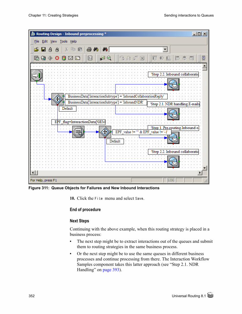
352 Universal Routing 8.1
Chapter 11: Creating Strategies Sending interactions to Queues
Figure 311: Queue Objects for Failures and New Inbound Interactions
10. Click the File menu and select Save.
End of procedure
Next Steps
Continuing with the above example, when this routing strategy is placed in a business process:
• The next step might be to extract interactions out of the queues and submit them to routing strategies in the same business process.
• Or the next step might be to use the same queues in different business processes and continue processing from there. The Interaction Workflow Samples component takes this latter approach (see “Step 2.1. NDR Handling” on page 393).

Business Process—User’s Guide 353
Chapter 11: Creating Strategies Compiling
CompilingThis section describes how to compile a routing strategy in the Routing Design window:
Procedure:Compiling a routing strategy
Purpose: To check whether the strategy can be executed and does not contain errors.
Start of procedure
1. Click the button for compiling (see Figure 312).
Figure 312: Compile Button
2. View the results of the compile. If the strategy compiles successfully, the following message appears (see Figure 313).
Figure 313: Message When Strategy Compiles Successfully
Note: This message also appears in the Errors in Strategy tab, which appears once you compile, at the bottom of the Routing Design window (see Figure 314).

354 Universal Routing 8.1
Chapter 11: Creating Strategies Checking Database Integrity
Figure 314: Errors in Strategy Tab
3. View the Errors in Strategy tab. If the strategy does not compile successfully, the Errors in Strategy tab details the error.
4. Correct the error and recompile until no more errors.
End of procedure
You may also wish to use the Check Integrity tool, which highlights invalid references in the Configuration Database.Using Check Integrity
Checking Database IntegrityYou can locate invalid Configuration Database object references within a saved or compiled strategy using the Check Integrity tool. The tool is located on the toolbar in the Routing Design window (see Figure 315).
Figure 315: Check Integrity Tool
Procedure:Using Check Integrity
Purpose: To check for invalid database references.

Business Process—User’s Guide 355
Chapter 11: Creating Strategies Checking Database Integrity
Start of procedure
1. Open the strategy if not already open. You can open by selecting the strategy in the Strategies list pane (see Figure 34 on page 59) or by using Edit/View Strategy in the Interaction Design window (see Figure 260 on page 305).
2. If you made any changes to the strategy since it was last saved or compiled, save the strategy again.
3. Click the icon for checking integrity (see Figure 315 on page 354) in the toolbar. The objects containing the invalid references are highlighted with a red border in the Routing Design window, and the Errors in Strategy output window appears below the Routing Design window listing the invalid references.
4. Double-click a highlighted object to open its properties dialog box.
5. Make corrections to the object as required. The highlight disappears when you close the properties dialog box for the object.
6. Use the Search or the Search and replace capabilities (see page 140) to search for all occurrences of an invalid reference.
End of procedure
Important Information
Keep the following points in mind when using Check Integrity:
• When a call should be routed to a Resource under a different Tenant using the routing rule Switch-to-Strategy, the Check Integrity function will always return an error.
• When Check Integrity is off, IRD allows the opening and editing of a loaded strategy.
• Before checking strategy integrity, save your changes. If you do not save your changes before using the Check Integrity tool, this error message appears:
Check Integrity Operation aborted
• If the Check Integrity tool is not available select View > Check Integrity to activate the tool. When the Check Integrity command is activated, all strategies and objects are checked. While IRD performs the check, you cannot perform any other operation.
• The Progress Bar indicates the progress of the integrity checking.
• Use the Compile command to check for strategy syntax errors.
• Turn off Check Integrity when updating permissions apply to a large number of objects. If Check Integrity is turned on, it could take a long time to update permissions, for example from No Access to Full Control.

356 Universal Routing 8.1
Chapter 11: Creating Strategies Adding a Strategy to a Business Process
Adding a Strategy to a Business ProcessStrategies unconnected to a business process can be found in the Independent Objects folder (see Figure 38 on page 63).
Procedure:Adding a strategy in the Independent Objects folder to a business process
Start of procedure
1. In the Interaction Design window object browser, Independent Objects folder, select the strategy.
2. Drag/drop it into the Strategies folder for the applicable business process.
3. Select Save from the File menu.
End of procedure
Procedure:Re-using a strategy already contained in a business process
If the strategy is already connected to a business process, you can still use it.
Start of procedure
1. Switch to the business process that contains the strategy by double-clicking it to make it active (highlighted). You can also select Open the Process from the shortcut menu.
2. Expand the Strategies folder where you will copy the strategy to.
3. Select the strategy that you wish to re-use so it is highlighted.
4. Drag only (don’t drop yet) to the Strategies folder for the applicable business process.
5. Place the mouse pointer directly over the Strategies folder.
6. When the mouse pointer becomes a left-pointing arrow, drop the strategy into the folder.
End of procedure

Business Process—User’s Guide 357
Chapter 11: Creating Strategies Editing/Viewing Strategies
Editing/Viewing StrategiesNote: You must deactivate a strategy before you can open it for editing or
viewing. For more information, see page 367.
You can edit or view a strategy that is not loaded on a virtual routing point from either the Interaction Design window or from the Routing Design window.
Procedure:Editing/viewing a strategy from the Interaction Design window
Start of procedure
1. Right-click the strategy name and select Edit/View Strategy from the menu (see Figure 316).
Figure 316: Edit/View Strategy From the Interaction Design Window

358 Universal Routing 8.1
Chapter 11: Creating Strategies Editing/Viewing Strategies
If you have access to the .rbn file (see “Graphical Portion of a Strategy” on page 172), the strategy opens for editing in the Routing Design window (see Figure 317 on page 358).
Figure 317: Strategy Available for Editing in Design View
2. If you have unsaved changes in the currently open business process, respond to the message that appears (see Figure 318).
Figure 318: Configuration Changed Prompt
End of procedure

Business Process—User’s Guide 359
Chapter 11: Creating Strategies Deleting Strategies
Procedure:Viewing a strategy from the IRD main window
To edit/view from the Strategies list pane in the IRD main window (see Figure 90 on page 115), use one of the methods below.
Start of procedure
1. If working in the Interaction Design window, minimize the window.
2. Open the window that contains the IRD main window.
3. Single-click the strategy to highlight and select Open from the File menu. As an alternative, double-click the strategy to open.
End of procedure
With either method, if you have access to the .rbn file (see “Graphical Portion of a Strategy” on page 172), the strategy opens for viewing/editing in the Routing Design window (see Figure 317 on page 358).
Deleting StrategiesYou can delete strategy that is not loaded on a virtual routing point in either the Interaction Design window or the Routing Design window.
Procedure:Deleting strategies from the Interaction Design window
Start of procedure
1. In the object browser (see Figure 37 on page 62), right-click the strategy.
2. Select Delete from the shortcut menu. The strategy is not deleted in the Configuration database, but only disappears from the business process that uses it. If you want to remove it from the Configuration Database, you must do so in the Routing Design window.
End of procedure
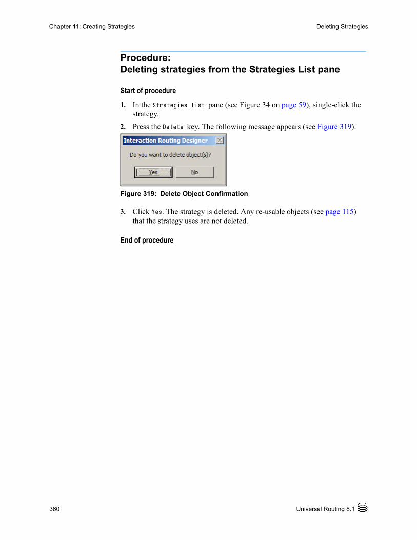
360 Universal Routing 8.1
Chapter 11: Creating Strategies Deleting Strategies
Procedure:Deleting strategies from the Strategies List pane
Start of procedure
1. In the Strategies list pane (see Figure 34 on page 59), single-click the strategy.
2. Press the Delete key. The following message appears (see Figure 319):
Figure 319: Delete Object Confirmation
3. Click Yes. The strategy is deleted. Any re-usable objects (see page 115) that the strategy uses are not deleted.
End of procedure

Business Process—User’s Guide 361
Chapter
12 Using a Business ProcessThis chapter provides step-by-step instructions for using business processes. It covers the following topics: Activating Strategies, page 361 Testing the Strategy, page 364 Verifying the Workflow, page 365 Deactivating/Unloading Strategies, page 366
Activating StrategiesBefore testing a routing strategy, you must load it on a virtual routing point in your Test environment (do not load it in your Production environment). Use the Strategy Activation Wizard for this purpose as described below.
Procedure:Loading a multimedia strategy on a virtual routing point
Start of procedure
1. As described in the eServices (Multimedia) 8.0 Deployment Guide, make sure a Multimedia Switch object is configured and available in IRD’s Monitoring view (see Figure 320 for an example).

362 Universal Routing 8.1
Chapter 12: Using a Business Process Activating Strategies
Figure 320: Example Multimedia Switch
2. Open the business process associated with the strategy by double-clicking it. Or use Open the Process from the shortcut menu.
3. Use one of the following methods to open the Strategy Activation Wizard: Highlight the business process name in the object browser and select
Deactivate Strategy(ies) from the Tools menu. Using this method, you can activate multiple strategies at once
Right-click the Strategy object in the object browser or workflow viewer and select Activate Strategy from the shortcut menu (see Figure 321).
Figure 321: Activate Strategy from Context Menu
With either method, the Strategy Activation Wizard launches (see Figure 322).

Business Process—User’s Guide 363
Chapter 12: Using a Business Process Activating Strategies
Figure 322: Strategy Activation Wizard, Start
4. Select an Interaction Server and click Next. Choose Universal Routing Server appears at the top of the wizard (see Figure 323).
Figure 323: Strategy Activation Wizard, Choose Universal Routing Server

364 Universal Routing 8.1
Chapter 12: Using a Business Process Testing the Strategy
5. Select a Universal Routing Server and click Activate. The next dialog box indicates the activation is done (see Figure 324).
Figure 324: Strategy Activation Wizard, Choose Universal Routing Server
End of procedure
If you do not have a Switch connection to Interaction Server, when you select Activate Strategy from the menu shown in Figure 321 on page 362, the Strategy Activation Wizard explains what to do next.
Note: It is possible to manually load strategies in Monitoring view (see Figure 67 on page 84). The Strategy Activation Wizard is the preferred method because it creates the virtual routing points for you. Similarly, when you use the Wizard to deactivate a strategy loaded on a virtual routing point (see Figure 68 on page 85), the Wizard also deletes the virtual routing points.
Testing the StrategyTesting the strategy is accomplished by using a combination of your e-mail client and Genesys Desktop, which flashes a yellow icon when an e-mail is received by a ready agent (see Figure 325).

Business Process—User’s Guide 365
Chapter 12: Using a Business Process Verifying the Workflow
Figure 325: Genesys Agent Desktop
For information about testing business processes, consult the eServices (Multimedia) 8.0 Deployment Guide.
Verifying the WorkflowA business process must be consistent. This means that:
• All routing strategies are valid.
• All non-dynamic queues have at least one Submitter object.

366 Universal Routing 8.1
Chapter 12: Using a Business Process Deactivating/Unloading Strategies
• All agent targets and routing strategies must have the appropriate number of connections.
• All interaction processing must have an end. The end can be specified by the IRD Stop Processing object or a special target (different from an agent and/or queue).
To verify a business process:
1. Select Options from the Tools menu.
2. Make sure the following option is selected:
Fix Referential Integrity Errors Automatically (on Load).
3. Select OK.
4. Close and re-open the business process.
5. Respond to any messages that might appear.
Deactivating/Unloading StrategiesNote: It is possible to unload strategies manually in Monitoring view (see
Figure 67 on page 84). Using Deactivate, as described below, is the preferred method because it gives you more options.
You must either deactivate or unload a strategy before you can open it for editing or viewing with Edit/View Strategy.
Procedure:Deactivating or unloading a strategy in a business process
Start of procedure
1. Open the Strategy Activation Wizard using one of the following methods:• Right-click the Strategy object in the object browser or workflow
viewer and select Deactivate Strategy from the shortcut menu. • Highlight the business process name in the object browser and select
Deactivate Strategy(ies) from the Tools menu. Using this method, you can deactivate multiple strategies at once
Depending on which method you use, the Deactivate <name> Strategies dialog box opens listing either one or all of the strategies contained in the business process that could be deactivated.
In the figure below, the business process contains one strategy (see Figure 326).
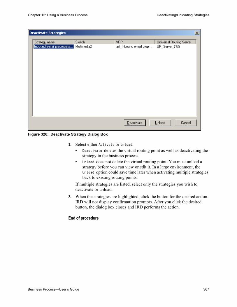
Business Process—User’s Guide 367
Chapter 12: Using a Business Process Deactivating/Unloading Strategies
Figure 326: Deactivate Strategy Dialog Box
2. Select either Activate or Unload.• Deactivate deletes the virtual routing point as well as deactivating the
strategy in the business process.• Unload does not delete the virtual routing point. You must unload a
strategy before you can view or edit it. In a large environment, the Unload option could save time later when activating multiple strategies back to existing routing points.
If multiple strategies are listed, select only the strategies you wish to deactivate or unload.
3. When the strategies are highlighted, click the button for the desired action. IRD will not display confirmation prompts. After you click the desired button, the dialog box closes and IRD performs the action.
End of procedure

368 Universal Routing 8.1
Chapter 12: Using a Business Process Deactivating/Unloading Strategies

Business Process—User’s Guide 369
Appendix
Business Process SamplesThis appendix discusses the Genesys-supplied business process samples. It builds on the information that is contained in “Using the Samples” on page 197 and covers the following topics: About the Samples, page 370 Viewing the Samples, page 372 ABC Simple BP, page 374 ABC Simple Chat BP, page 379 ABC Simple MMS, page 381 ABC Simple SMS Paging, page 382 Web Callback, page 382 Default BP, page 387 Step-Numbered Business Processes, page 389 Step 1. Pre-Routing, page 391 Step 2.1. NDR Handling, page 393 Step 2.2. Inbound Collaboration Reply, page 394 Step 2.3. New Inbound E-mails, page 396 Step 3.1. Processing By Agents, page 399 Step 3.2. QA Review, page 401 Step 3.3. Forwarding, page 403 Step 3.4. Redirecting, page 405 Step 4. Outbound Sending, page 407 How To: Business Processes, page 409 How To: Apply Escalation Procedure, page 411 How To: Attach Classification Categories and Use Attach Categories
Object, page 413 How To: Attach Classification Categories and Use Multi-Screen Object,
page 419 How To: Conduct a Survey by Using Email, page 425 How To: Get Credit Card Number From the E-mail, page 430 How To: Handle Fax Interactions, page 434 How To: Identify Contact and Create Interaction in UCS, page 441
370 Universal Routing 8.1
Appendix : Business Process Samples About the Samples
How To: Place the Interaction Into the Workbin, page 445 How To: Screen Multiple Rules and Use Screening Switch, page 449
About the SamplesBecause each company has its own environment and different requirements, supplying business process samples that accurately reflect all real-word business scenarios is not possible. Therefore, do not consider the Genesys-supplied Interaction Workflow Samples suitable for a Production environment, but instead as demonstrations of one way in which to implement various types of functionality. Use them as a starting point to develop your own customized business processes adjusted to your company’s specific needs.
Through its Interaction Workflow Samples component (shown in Figure 327 on page 373), Genesys provides the following business processes:
• ABC Simple BP (page 374), which is a basic business process useful to get a concept and check the samples installation.
• ABC Simple Chat BP (page 379), which offers minimal chat interaction processing.
• ABC Simple MMS (page 381), which offers minimal inbound MMS (Multimedia Messaging Service) processing.
• ABC Simple SMS Paging (page 382), which offers minimal SMS (Short Messaging Service) processing.
• Default BP (page 387), which is a complex business process that has a lot of functionality. See “Functionality Demonstrated in the Samples”.
• The step-numbered samples break down Default BP into functionally-themed components:
Step 0. Common Components (see Table 30 on page 389)
Step 1. Pre-routing (page 391)
Step 2.1. NDR Handling (page 393)
Step 2.2. Inbound Collaboration Reply (page 394)
Step 2.3. New Inbound E-mails (page 396)
Step 3.1 Processing by Agents (page 399)
Step 3.2. QA Review (page 401)
Step 3.3. Forwarding (page 403)
Step 3.4. Redirecting (page 405)
Step 4. Outbound Sending (page 407)
• The how-to business processes:
How to: apply escalation procedure (page 411)
How to: attach classification categories & use attach categories
object (page 413)

Business Process—User’s Guide 371
Appendix : Business Process Samples About the Samples
How to: attach classification categories & use multi-screen object
(page 419)
How to: get credit card number from the e-mail (page 430)
How to: handle fax interactions (page 434)
How to: identify contact and create interaction in UCS (page 441)
How to: place the interaction into the workbin (page 445)
How to: screen with multiple rules and use multi-screen object
(page 449)
• Web Callback (page 382) offers web callback processing.
Samples Functionality
The Interaction Workflow Samples component supplies the following functionality:
• Pre-routing based on interaction sub-type (see page 391)
• Routing interactions to the original agent (see page 393)
• Screening of inbound interactions (see page 396)
• Attaching classification Categories (see page 419)
• Processing of attached data (see page 393)
• Redirecting interactions (see page 405)
• Forwarding interactions (see page 403)
• Collaboration reply sending (see page 394)
• Automatic treatment with an acknowledgement e-mail (see page 451)
• Autoresponse e-mail when applicable (see page 451)
• Placing interactions in workbins (see page 445)
• Escalating overdue interactions to supervisor workbins (see page 445)
• Routing to agents (see page 399)
• Assigning failure codes to interactions (see page 451)
• Promoting an interaction that failed pre-routing to the next process (see page 391)
• Routing interactions for QA review (see page 401)
• Skill-based review of agent response (see page 401)
• Re-processing interactions that failed QA review (see page 401)
• Quality control for outbound interactions based on screening (see page 407)
• Re-processing interactions that failed quality control (see page 401)
• Sending e-mail responses to customers (see page 407)
• Re-processing interactions that failed sending (see page 407)

372 Universal Routing 8.1
Appendix : Business Process Samples Viewing the Samples
• Stopping an interaction with a reason code (see page 378)
• Handling fax interactions (see page 434)
• Identify customer contacts and create interaction records (see page 441)
• Get credit card information from an interaction (see page 430)
Note: In order to understand fully a business process, you must understand its strategies. Universal Routing 8.1 Strategy Samples details many of the strategies that are found in the Genesys Multimedia Interaction Workflow Samples component.
Viewing the SamplesOnce the samples are installed (as described in the eServices (Multimedia) 8.0 Deployment Guide) you can view them in the Interaction Design window (see Figure 327).

Business Process—User’s Guide 373
Appendix : Business Process Samples Viewing the Samples
Figure 327: Interaction Workflow Samples
• For information about printing a business process, see page 76.
• For information about printing the strategies contained in a business process, see page 109.
• To change to a different business process, double-click the business process.
Properties Dialog Boxes for Strategy Objects
When you load the samples, as described in the eServices (Multimedia) 8.0 Deployment Guide, part of the installation process involves using Knowledge

374 Universal Routing 8.1
Appendix : Business Process Samples ABC Simple BP
Manager to import the file UCS_impex.kme. This file contains Screening Rules and other objects found in the Universal Contact Server Database, which must be synchronized with objects in the Configuration Database. If Screening Rules or other Knowledge Manager objects do not display in the object properties dialog boxes for the sample strategies, check whether this step was performed.
If the file was imported and the properties dialog boxes still do not display the proper objects, one possible reason may be that the database identifiers (IDs) of the default Screening Rules and/or other objects have changed. In this case, use Knowledge Manager to reimport the ucs_impex.kme file. In the Import dialog box, clear Preserve uniqueness of objects by creation of new UCS ids.
Warning! Normally, it is very risky to not preserve uniqueness (that is why the preceding check box is selected by default). However, when you are importing the ucs_impex.kme file related to the Interaction Workflow Samples, you do NOT want to change any of the database IDs that are associated with the default Screening Rules and other objects. Leaving this box unchecked will ensure that these rules are not assigned new UCS IDs.
ABC Simple BPABC Simple BP in Figure 327 on page 373 is a basic version of a real-life business process. Figure 328 shows the business process.
Figure 328: ABC Simple BP
The business scenario: Deliver inbound interactions to the appropriate agent and then send out the response created by that agent. The sample has no other functionality and can correctly process only new inbound customer interactions.

Business Process—User’s Guide 375
Appendix : Business Process Samples ABC Simple BP
Processing Flow
Any e-mail that is received in the contact center is submitted by E-mail Server to the Inbound queue (see Figure 328 on page 374). Using Inbound view that has no Conditions or Order By information (see page 273), interactions are extracted from the queue and passed to the Process ABC routing strategy.
Process ABC Routing Strategy
This routing strategy contains only an Entry object, a Route Interaction object, and an Exit object (see Figure 329).
Figure 329: Process ABC Routing Strategy
Open the Route Interaction object Properties dialog box (see Figure 330).

376 Universal Routing 8.1
Appendix : Business Process Samples ABC Simple BP
Figure 330: Process ABC Routing Strategy
You will see that the Interaction Queue tab specifies:
• The Genesys predefined queue Stop Processing(_STOP_) for the existing interaction (the customer’s original e-mail for which processing is now ending). Stop Processing(_STOP_) is represented by the first Stop object in Figure 328 on page 374, which is a strategy-linked node (see page 34).
• The queue Outbound queue for the new interaction that will be created, which will ultimately be sent to the customer. This queue is the Outbound queue strategy-linked node in Figure 328 on page 374.
In the Target Selection tab in Figure 330 on page 376, you will see that the interaction is routed to a member of the Agent Group called E-mail distribution. This target is represented as the E-mail distribution person strategy-linked node (see page 34) in Figure 328 on page 374.
The agent generates a response and places it in the Outbound Queue. Interactions are extracted using the Outbound view (with no Condition or Order By information as shown in Figure 222 on page 273) and submitted to the routing strategy Send ABC.
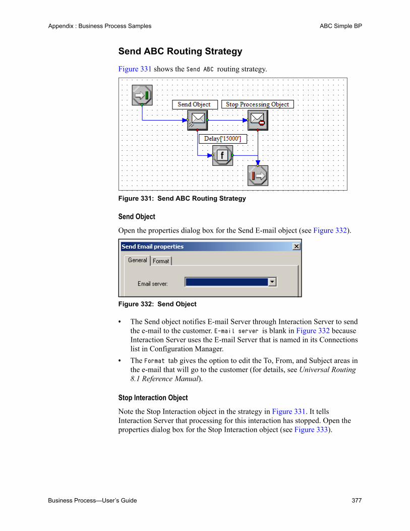
Business Process—User’s Guide 377
Appendix : Business Process Samples ABC Simple BP
Send ABC Routing Strategy
Figure 331 shows the Send ABC routing strategy.
Figure 331: Send ABC Routing Strategy
Send Object
Open the properties dialog box for the Send E-mail object (see Figure 332).
Figure 332: Send Object
• The Send object notifies E-mail Server through Interaction Server to send the e-mail to the customer. E-mail server is blank in Figure 332 because Interaction Server uses the E-mail Server that is named in its Connections list in Configuration Manager.
• The Format tab gives the option to edit the To, From, and Subject areas in the e-mail that will go to the customer (for details, see Universal Routing 8.1 Reference Manual).
Stop Interaction Object
Note the Stop Interaction object in the strategy in Figure 331. It tells Interaction Server that processing for this interaction has stopped. Open the properties dialog box for the Stop Interaction object (see Figure 333).

378 Universal Routing 8.1
Appendix : Business Process Samples ABC Simple BP
Figure 333: Stop Interaction Object
The Stop Interaction object specifies a Reason Code. Genesys predefines the Sent Reason Code in Configuration Manager. The Stop Interaction object also specifies that Universal Contact Server (UCS) should be notified that processing for this interaction (the new interaction) has stopped.
When a Stop Interaction object is used inside a strategy, it generates a Stop strategy linked node (see page 34). You can see this strategy-linked node as the second Stop node in Figure 328 on page 374.
Function Object
The Send ABC routing strategy that is shown in Figure 331 on page 377 also contains a Function object. If there is an error in sending, the interaction goes out the bottom port of the Send object to a Function object. Open the properties dialog box for the Function object (see Figure 334).

Business Process—User’s Guide 379
Appendix : Business Process Samples ABC Simple Chat BP
Figure 334: Function Object
Strategy execution is delayed for the specified number of milliseconds. After this number of milliseconds, the interaction is returned to the same queue for the next send attempt.
ABC Simple Chat BPABC Simple Chat BP is very similar to ABC Simple BP. The main difference is that ABC Simple Chat BP contains a strategy (Chat strategy - create transcript e-mail) that uses the Chat Transcript object to request E-mail Server to generate an e-mail that has the customer’s chat transcript attached. Figure 335 shows the business process.

380 Universal Routing 8.1
Appendix : Business Process Samples ABC Simple Chat BP
Figure 335: ABC Simple Chat BP
Note: The objects within this business process have been repositioned so that all are visible on a page.
The business scenario: Determine whether an interaction should be processed immediately (such as a chat) or at a later time. If the interaction is the result of a chat session, request E-mail Server to generate an e-mail that has the chat transcript attached and send it to the customer.
Note: For more information about this business process, including its queues, views and strategies, see Universal Routing 8.1 Strategy Samples.

Business Process—User’s Guide 381
Appendix : Business Process Samples ABC Simple MMS
ABC Simple MMSABC Simple MMS provides basic MMS processing functionality. The business process contains one strategy: MMS Inbound Processing. Figure 336 shows the business process.
Figure 336: ABC Simple MMS BP
The business scenario: Deliver inbound MMS interactions to the appropriate agent. The agent can see the interaction’s content (subject, text and multimedia elements) and the interaction’s history of a contact (author of the MMS message). The sample has no other functionality and can correctly process new inbound customer interactions only.
Note: For more information about this business process, including its strategies, see the Universal Routing 8.1 Strategy Samples.

382 Universal Routing 8.1
Appendix : Business Process Samples ABC Simple SMS Paging
ABC Simple SMS PagingABC Simple SMS Paging provides basic SMS processing functionality. The business process contains two strategies: SMS Inbound and SMS Outbound. Figure 337 shows the business process.
Figure 337: ABC Simple SMS Paging BP
The business scenario: Deliver inbound SMS interactions to the appropriate agent. The agent can see the interaction’s content and the interaction’s history of a contact (author of the SMS message). The agent can reply to the contact by using an outbound SMS message. The outbound interaction is placed into an outbound interaction queue. The SMS Outbound routing strategy fetches the outbound interaction and sends it to the contact by using SMS Server. The sample has no other functionality and can correctly process new inbound customer interactions only.
Web CallbackWebCallback provides basic web callback processing. The business process contains the following strategies:
• Delivering strategy
• Expired Conference Callbacks strategy
• Expired Transfer Callbacks strategy
Note: For more information about this business process, including its strategies, see Universal Routing 8.1 Strategy Samples.

Business Process—User’s Guide 383
Appendix : Business Process Samples Web Callback
• Outbound notification email sending strategy
• Preprocessing strategy
• Rescheduled by Agent strategy
• Rescheduled by Customer strategy
• Stop By Agent strategy
• Stop By Customer strategy
The WebCallback business process contains the following subroutines:
• Check Customer Session State
• Check Interaction
• Check Maximum Attempts
• Check Maximum Waiting Time
• Increment Number of Attempts
• Schedule Web Callback
• Send Email Notification
• Stop Web Callback
Figure 338 shows the business process.
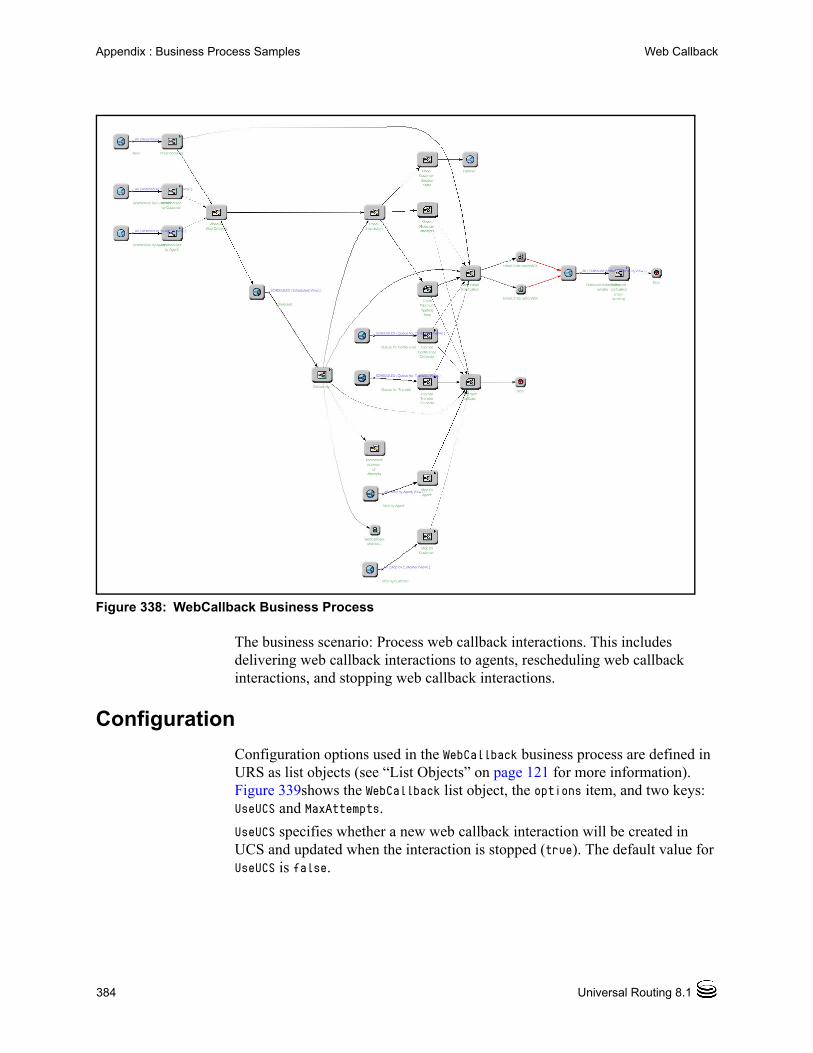
384 Universal Routing 8.1
Appendix : Business Process Samples Web Callback
Figure 338: WebCallback Business Process
The business scenario: Process web callback interactions. This includes delivering web callback interactions to agents, rescheduling web callback interactions, and stopping web callback interactions.
Configuration
Configuration options used in the WebCallback business process are defined in URS as list objects (see “List Objects” on page 121 for more information). Figure 339shows the WebCallback list object, the options item, and two keys: UseUCS and MaxAttempts.
UseUCS specifies whether a new web callback interaction will be created in UCS and updated when the interaction is stopped (true). The default value for UseUCS is false.

Business Process—User’s Guide 385
Appendix : Business Process Samples Web Callback
MaxAttempts specifies the maximum number of attempts that can be made to deliver the interaction to an agent. The default value is 5. MaxAttempts can be set to any valid integer.
Figure 339: WebCallback List Object
Processing Flow
This section outlines the processing flow of the WebCallback business process. It is divided into the following topics:
• Preprocessing
• Delivering
• Rescheduling by Agent
• Rescheduling by Customer
• Stopping by Strategy
• Stopping by Agent
• Stopping by Customer
Note: For more information about this business process, including its strategies, see Universal Routing 8.1 Strategy Samples.

386 Universal Routing 8.1
Appendix : Business Process Samples Web Callback
Preprocessing
The Preprocessing phase of the business process updates all necessary interaction business data parameters, sets the correct ScheduledAt key-value pair, and submits the interaction to the Scheduled queue.
Optional steps include the following:
• Create the contact and interaction in UCS.
• Send a confirmation e-mail to the customer.
Delivering
The Delivering phase of the business process finds a target and delivers the web callback to an agent.
The interaction is redirected to the Stop queue if:
• The end time for the callback has passed.
• A target is not found and the end time for the callback has passed.
The interaction is redirected to the Failover queue if the WCB_CUSTOMER_SESSION_STATE key-value pair value is set to active. This will prevent double calls to customers in case of system failover.
Rescheduling by Agent
All of the the necessary interaction business data parameters are updated, and the correct ScheduledAt key-value pair is set. The interaction is submitted to the Scheduled queue.
The number of attempts is updated.
The interaction is redirected to the Stop queue if:
• The number of attempts is too high.
• The end time for callback has passed.
Rescheduling by Customer
All of the the necessary interaction business data parameters are updated, and the correct ScheduledAt key-value pair is set. The interaction is submitted to the Scheduled queue.
The interaction is redirected to the Stop queue if:
• The number of attempts is too high.
• The end time for callback has passed.

Business Process—User’s Guide 387
Appendix : Business Process Samples Default BP
Stopping by Strategy
All of the necessary interaction business data parameters are updated. The interaction is stopped.
The status is updated to Completed.
Optional steps include:
• Update the interaction in UCS.
• Send a notification e-mail about the unsuccessful web callback to the customer.
Stopping by Agent
All of the necessary interaction business data parameters are updated. The interaction is stopped.
The status is updated to Completed.
Optional steps include:
• Update the interaction in UCS.
Stopping by Customer
All of the necessary interaction business data parameters are updated. The interaction is stopped.
The status is updated to Completed.
Optional steps include:
• Update the interaction in UCS.
Default BPDefault BP is an example of a complex business process that encompasses the functional areas that are isolated in the step-numbered business processes (see Table 30 on page 389). It combines a large number of different tasks into a single business process. Contrast this with the “Step-Numbered Business Processes” on page 389 in which the tasks are divided into smaller business processes that are connected via queues (see page 199).
Figure 340 shows a high-level view of the start of Default BP.

388 Universal Routing 8.1
Appendix : Business Process Samples Default BP
Figure 340: Default BP
Notes: Select Zoom Out from the context menu to view more of a large business process.
Figure 340 reflects the default arrangement of the icons in the viewer. You can always return to the default positioning at any time by selecting Arrange Objects from the business process menu.
Each functional area in Default BP is explained in the step-numbered business processes.
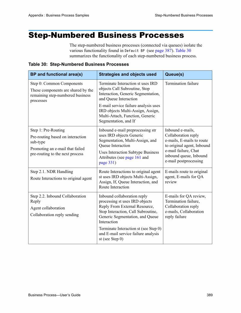
Business Process—User’s Guide 389
Appendix : Business Process Samples Step-Numbered Business Processes
Step-Numbered Business ProcessesThe step-numbered business processes (connected via queues) isolate the various functionality found in Default BP (see page 387). Table 30 summarizes the functionality of each step-numbered business process.
Table 30: Step-Numbered Business Processes
BP and functional area(s) Strategies and objects used Queue(s)
Step 0: Common Components
These components are shared by the remaining step-numbered business processes
Terminate Interaction st uses IRD objects Call Subroutine, Stop Interaction, Generic Segmentation, and Queue Interaction
E-mail service failure analysis uses IRD objects Multi-Assign, Assign, Multi-Attach, Function, Generic Segmentation, and If
Termination failure
Step 1: Pre-Routing
Pre-routing based on interaction sub-type
Promoting an e-mail that failed pre-routing to the next process
Inbound e-mail preprocessing str uses IRD objects Generic Segmentation, Multi-Assign, and Queue Interaction
Uses Interaction Subtype Business Attributes (see page 161 and page 331)
Inbound e-mails, Collaboration reply e-mails, E-mails to route to original agent, Inbound e-mail failure, Chat inbound queue, Inbound e-mail postprocessing
Step 2.1. NDR Handling
Route Interactions to original agent
Route Interactions to original agent st uses IRD objects Multi-Assign, Assign, If, Queue Interaction, and Route Interaction
E-mails route to original agent, E-mails for QA review
Step 2.2. Inbound Collaboration Reply
Agent collaboration
Collaboration reply sending
Inbound collaboration reply processing st uses IRD objects Reply From External Resource, Stop Interaction, Call Subroutine, Generic Segmentation, and Queue Interaction
Terminate Interaction st (see Step 0) and E-mail service failure analysis st (see Step 0)
E-mails for QA review, Termination failure, Collaboration reply e-mails, Collaboration reply failure

390 Universal Routing 8.1
Appendix : Business Process Samples Step-Numbered Business Processes
Step 2.3 New Inbound E-mails Handling
Screening of inbound e-mails
Automatic treatment with an acknowledgement e-mail
Autoresponse when applicable
Assigning failure codes
Preliminary e-mail screening st strategy uses IRD objects Screen, Call Subroutine, Generic Segmentation, Function, If, Queue Interaction, Stop, Autoresponse, and Acknowledgement
Terminate Interaction st (see Step 0) and E-mail service failure analysis st (see Step 0)
Inbound e-mail postprocessing, Redirect e-mail, Forward e-mails, Preprocessing failure, Termination failure, E-mails for processing by agents, Outbound e-mails
Step 3.1. Processing by Agents
Routing to agents
Processing by agents
E-mail distribution for processing st contains IRD object Queue Interaction
E-mails for processing by agents, E-mails for QA review, Forward e-mails
Step 3.2: Routing E-mails for QA Review
Processing of attached data
Skill-based review of agent response
Re-processing e-mails that failed quality control
Re-processing e-mails that failed sending
Outbound e-mail 65x QA st uses IRD objects Multi-Assign, Assign, Generic Segmentation, Route Interaction, Queue E-mail, If, and Function
E-mails for QA review, Quality Control, E-mails failed QA, Outbound e-mails
Step 3.3. Forwarding
Stopping an e-mail with a reason code
Forward e-mail processing st uses IRD objects Forward E-mail, Stop Interaction, Call Subroutine, Generic Segmentation, and Function
Terminate Interaction st (see Step 0) and E-mail service failure analysis st (see Step 0)
Forward e-mails, Termination failure, Forward e-mail failure, Outbound e-mails
Table 30: Step-Numbered Business Processes (Continued)
BP and functional area(s) Strategies and objects used Queue(s)

Business Process—User’s Guide 391
Appendix : Business Process Samples Step 1. Pre-Routing
This appendix now details each step-numbered business process. In addition to detailing interaction flow, the descriptions show how individual business processes can be connected via queues.
Note: After each step-numbered business process description, a graphic depicts the Default BP area that supplies the same functionality.
Step 1. Pre-RoutingThe purpose of this business process is to determine if an inbound interaction is new or has previously been processed by Genesys and process the interaction accordingly. It does this through the existence (or nonexistence) of an Interaction Subtype code.
Figure 341 on page 392 shows the Step 1. Pre-Routing business process.
Step 3.4. Redirecting
Redirecting an e-mail
Redirect e-mail processing st uses IRD objects Redirect E-mail, Stop Interaction, Function, Queue Interaction, Call Subroutine, and Generic Segmentation
Terminate Interaction st (see Step 0) and E-mail service failure analysis st (see Step 0)
Redirect e-mail, Termination failure, Redirect e-mail failure, Outbound e-mails
Step 4. Outbound Sending
Quality control for outbound e-mails based on screening
Sending e-mail responses to customers
Quality Control st uses IRD objects Screen, If, Queue E-mail, Call Strategy, and Function
Outbound e-mail sending st uses IRD objects Send E-mail, Stop Interaction, Call Subroutine, Generic Segmentation, Function, Queue Interaction
Terminate Interaction st (see Step 0) and E-mail service failure analysis st (see Step 0)
Quality Control, Outbound e-mails, E-mail failure analysis, Termination failure, E-mails send error
Table 30: Step-Numbered Business Processes (Continued)
BP and functional area(s) Strategies and objects used Queue(s)

392 Universal Routing 8.1
Appendix : Business Process Samples Step 1. Pre-Routing
Figure 341: Step 1. Pre-Routing
Note: Note the up arrows located on the queue nodes in Figure 341. This indicates a queue that originated in another business process as described on page 28 and shown in Figure 9 on page 28.
Processing Objects
This section describes the various objects in Figure 341 on page 392.
A view (Inbound e-mails) that has no Conditions (see Figure 222 on page 273) or Order By information (see Figure 224 on page 274) extracts e-mails from the Inbound e-mails queue (see Figure 3 on page 23) and submits them to the Inbound e-mail preprocessing st strategy. Incoming e-mails may be new ones from customers or they may be e-mails that have

Business Process—User’s Guide 393
Appendix : Business Process Samples Step 2.1. NDR Handling
already gone through Genesys e-mail processing as indicated by the assignment of an Interaction Subtype (see Figure 148 on page 164).
The flow of an e-mail through the strategy is determined by the existence or nonexistence of an Interaction Subtype (see page 331).
• If the e-mail has an NDR Interaction Subtype, it is sent to a queue for delivery to the original agent.
• If the e-mail has an InboundCollaborationReply Interaction Subtype, it is send to a queue handling collaboration replies from one agent to another.
• If the e-mail does not contain either of these Interaction Subtypes, the strategy looks for an inbound preprocessing failure flag. If found, the e-mail is sent to a queue for inbound e-mail failures. If not found, the e-mail is sent to a queue for new inbound e-mails.
To see the IRD objects that are used in the Inbound e-mail preprocessing strategy in Figure 341 on page 392, see the Universal Routing 8.1 Strategy Samples.
Step 2.1. NDR HandlingThe purpose of this business process is to continue the processing started in Step 1. Pre-Routing. It processes interactions with a Non Delivery Report (NDR) Interaction Subtype code by sending them to either the original agent or, if the agent name cannot be found, to a queue for QA review.
Figure 342 shows the Step 2.1. NDR Handling business process.
Figure 342: Step 2.1: Non-Delivery Report Handling
Processing Objects
This section describes the various objects in Figure 342.

394 Universal Routing 8.1
Appendix : Business Process Samples Step 2.2. Inbound Collaboration Reply
The E-mails to route to original agent queue is the same queue that is shown in Step 1. Pre-Routing (see Note on page 392). A view that has no Conditions (see Figure 222 on page 273) or Order By information (see Figure 224 on page 274) attached to the queue extracts e-mails. Interactions are submitted to the Route e-mail to original agent st strategy.
The Route e-mail to original agent st strategy demonstrates how to route a customer reply e-mail back to the agent that handled the original e-mail. It checks whether the original agent employee ID or QA reviewer employee ID is contained in the interaction attached data.
• If a variable contains the name of the original agent, the e-mail is routed to the original agent.
• If this same variable does not contain the name of the original agent, the e-mail is routed to a queue for QA review.
Note: To see the IRD objects that are used in the Route Interaction to original agent st strategy, see the Universal Routing 8.1 Strategy Samples.
Step 2.2. Inbound Collaboration ReplyThe purpose of this business process is to continue the processing started in Step 1. Pre-Routing. It processes interactions with an Inbound Collaboration Reply Interaction Subtype code indicating one resulting from two agents collaborating on a customer reply. Figure 343 shows the Step 2.2 Inbound Collaboration Reply business process.

Business Process—User’s Guide 395
Appendix : Business Process Samples Step 2.2. Inbound Collaboration Reply
Figure 343: Step 2.2. Inbound Collaboration Reply
Collaboration replies are e-mails from external resources. An external resource is a name for any object outside the contact center. It may be an external agent or another contact center.
A collaboration reply inbound e-mail arrives as a result of the following actions:
• The parent e-mail is forwarded by an agent (via the Forward E-mail object) requesting collaboration with another agent.
• The collaborating agent constructs a response.

396 Universal Routing 8.1
Appendix : Business Process Samples Step 2.3. New Inbound E-mails
• The collaborating agent sends the reply back to the requesting agent creating a collaboration reply inbound e-mail.
Processing Objects
This section describes the various objects in Figure 343 on page 395.
The Collaboration reply e-mails queue is the same queue that is shown in Figure 341 on page 392 (see Note on page 392). In Default BP, this queue connects the Step 1. Pre-routing business process with the Step 2.2 Inbound Collaboration Reply business process.
A view that has no Conditions (see Figure 222 on page 273) or Order By information (see Figure 224 on page 274) extracts e-mails from the queue.
A submitter submits them to the Inbound collaboration reply processing st strategy.
A Reply From External Resource (see page 204) object in the strategy takes the collaboration reply as input, extracts the reply text from it, creates a customer reply outbound e-mail with it, and places the e-mail in an interaction queue (E-mails for QA review).
A Stop Interaction object notifies Interaction Server that processing is finished.
Error Handling
The following objects in Figure 343 on page 395 are the result of error handling: Collaboration reply failure queue, E-mail service failure analysis st strategy, and Terminate Interaction st strategy.
Note: For details on strategy error handling, as well as the IRD objects used in the Inbound collaboration reply processing strategy, see Universal Routing 8.1 Strategy Samples.
+
Step 2.3. New Inbound E-mailsThe purpose of this business process is to continue the processing started in Step 1. Pre-Routing. It processes interactions without an Inbound Collaboration Reply or NDR Interaction Subtype code (or preprocessing failure flag) indicating a new inbound interaction from a customer. Figure 344 shows the Step 2.3. New Inbound E-mails business process.

Business Process—User’s Guide 397
Appendix : Business Process Samples Step 2.3. New Inbound E-mails
Figure 344: Step 2.3. New Inbound E-mails
Processing Objects
This section describes the various objects in Figure 344 on page 397.
This business process begins with the Inbound e-mail postprocessing queue, which is one of four output queues that are shown in Figure 341 on page 392. In Default BP, this queue connects the Step 1. Pre-routing business process

398 Universal Routing 8.1
Appendix : Business Process Samples Step 2.3. New Inbound E-mails
with the Step 2.3. New Inbound E-mails business process (see Note on page 392).
A view that has no Conditions (see Figure 222 on page 273) or Order By information (see Figure 224 on page 274) extracts e-mails from the queue.
A submitter submits them to the Preliminary e-mail screening st routing strategy.
This strategy screens e-mails by using three Screening Rules (see page 185).
1. If the screening using the first rule (Auto Response Available) produces a match, an Autoresponse object (Autoresponse strategy-linked node in Figure 344 on page 397) attaches a Standard Response to the interaction and places the interaction in the Outbound e-mails queue.
2. If the first screening does not produce a match, a second screening occurs using a different rule (Warranty Problem). Results are written to a variable, which is subsequently used in an If expression. If the expression is true (Screening Rule match found), the interaction goes to the queue Forward e-mails. If the expression is false (no match), the interaction goes through a third screening.
3. If the second screening does not produce a match, a third screening occurs using a different Screening Rule (Tech Support). Results are again written to a variable, which is subsequently used in an If expression.
If the expression is true, the interaction requires a technical support agent so it goes to the Redirect e-mails queue. A Stop object then notifies Interaction Server that processing has stopped since the Redirect object is used for e-mails do not require any further processing (see page 204).
If the expression is false (no match), an Acknowledgement object (Acknowledge strategy-linked node in Figure 344 on page 397) attaches a Standard Response to the interaction and places it in the E-mails for processing by agents queue.
The following objects in Figure 344 on page 397 are the result of error handling:
E-mail service failure analysis st strategy
Terminate Interaction st strategy
Preprocessing failure queue
Termination failure queue
Note: For details on strategy error handling, see Universal Routing 8.1 Strategy Samples.

Business Process—User’s Guide 399
Appendix : Business Process Samples Step 3.1. Processing By Agents
Step 3.1. Processing By AgentsThe purpose of this business process is to continue the processing from Step 2.3 New Inbound E-mails. It processes interactions in the E-mails for processing by agents queue by sending them to members of an agent group. Once an agent is finished, the interaction is placed in a queue for quality assurance review.
Figure 345 shows the Step 3.1. Processing By Agents business process.
Figure 345: Step 3.1. Processing by Agents
Processing Objects
This section describes the various objects in Figure 345.
The E-mails for processing by agents queue is the same queue that is shown in Figure 344 on page 397 (see Note on page 392). In Default BP, this queue connects the Step 2.3. New Inbound E-mails Handling business process with the Step 3.1. Processing By Agents business process. This queue is used when a Standard Response cannot be used and the interaction does not require redirecting as described on page 398.
A view that has no Conditions (see Figure 222 on page 273) or Order By information (see Figure 224 on page 274) extracts e-mails from the queue.
A submitter submits them to the E-mail distribution for processing st strategy.
This routing strategy contains only an Entry object, a Route Interaction object, and Exit object. Figure 346 on page 400 shows the E-mail distribution for processing st strategy.

400 Universal Routing 8.1
Appendix : Business Process Samples Step 3.1. Processing By Agents
Figure 346: E-mail Distribution For Processing Strategy
The Route Interaction object routes to an Agent Group target type. The name of the Agent Group is E-mail distribution for processing (see Figure 347).
Figure 347: Route Interaction Properties Dialog Box
StatAgentsAvailable is specified under Statistics, Max. URS uses this statistic to select a routing target if more than one target is available. For more information about this statistic, see the Universal Routing 8.1 Reference Manual.
The Route Interaction object also has an Interaction Queue tab (see Figure 348).

Business Process—User’s Guide 401
Appendix : Business Process Samples Step 3.2. QA Review
Figure 348: Route Interaction Properties Dialog Box, Interaction Queue Tab
The Interaction Queue tab gives the option of specifying two types of queues.
1. Queue for existing interaction. If the agent can’t handle the e-mail and determines it should be forwarded to another agent, the Description field provides a desktop hint for the agent on the Forward e-mails queue. (The existing interaction is being forwarded, but will eventually come back to the forwarding agent.) This selection generates the Forward e-mails strategy-linked queue node (see page 34) in Figure 345 on page 399.
Just as in Figure 330 on page 376, the Genesys predefined queue Stop Processing(_STOP_) indicates to Interaction Server that processing of the existing interaction has stopped for now (because the e-mail is being forwarded). This entry generates the Stop strategy-linked node in Figure 345 on page 399.
2. Queue for new interaction. If the agent creates a new interaction in the form of an e-mail response to the customer, the Description field is used by the desktop to provide a description for the agent on the purpose of the E-mails for QA review queue. This entry generates E-mails for QA review strategy-linked node in Figure 345 on page 399.
Step 3.2. QA ReviewThe purpose of this business process is to continue the processing from Step 3.1 Processing by Agents. It processes interactions in the E-mails for QA

402 Universal Routing 8.1
Appendix : Business Process Samples Step 3.2. QA Review
review queue by determining whether QA review is necessary and then taking the appropriate action.
Figure 349 on page 402 shows the Step 3.2. QA Review business process.
Figure 349: Step 3.2. QA Review
Processing Objects
This section describes the various objects in Figure 349.
The E-mails for QA review queue in Figure 349 is the same queue that is shown in Figure 345 on page 399 (see Note on page 392). In Default BP, this queue connects the Step 3.1. Processing by Agents business process with the Step 3.2. QA Review business process.
A view (E-mails for QA review) that has no Conditions (see Figure 222 on page 273) or Order By information (see Figure 224 on page 274) extracts e-mails from the queue.
A submitter submits interactions to the Outbound e-mail 65x QA st strategy.
This strategy determines whether an agent’s e-mail response has undergone QA review. If the existence of a flag in the interaction indicates that QA has already reviewed, the response goes to the queue Quality control. If QA has not reviewed, the strategy determines whether QA review is necessary based on the skill level of the handling agent.
• If the responding agent has the default skill level or higher, QA review is not necessary so the e-mail goes to a queue for sending to the customer (Outbound e-mails).

Business Process—User’s Guide 403
Appendix : Business Process Samples Step 3.3. Forwarding
• If the responding agent does not have the default skill level or higher, the e-mail response is routed to QA for checking (E-mail QA review group). If QA review does not uncover any errors, the e-mail goes to the queue Outbound e-mails. If the review uncovers errors, the e-mail goes to the queue E-mails failed QA.
Note: For details on strategy error handling, as well as the IRD objects used in the Outbound e-mail 65x QA strategy, see Universal Routing 8.1 Strategy Samples.
Step 3.3. Forwarding The purpose of this business process is to continue the processing started in Step 2.3 New Inbound E-mails. It forwards interactions in the Forward e-mails queue with the expectation of getting a response back. Figure 350 shows Step 3.3. Forwarding business process.
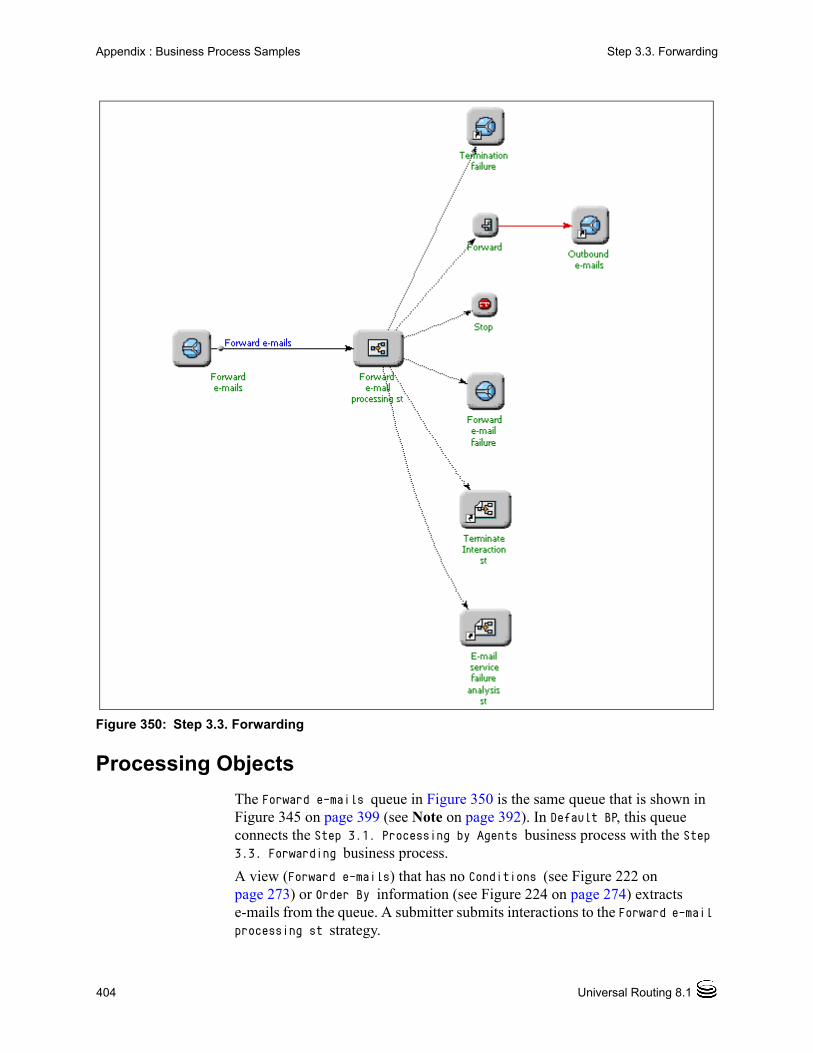
404 Universal Routing 8.1
Appendix : Business Process Samples Step 3.3. Forwarding
Figure 350: Step 3.3. Forwarding
Processing Objects
The Forward e-mails queue in Figure 350 is the same queue that is shown in Figure 345 on page 399 (see Note on page 392). In Default BP, this queue connects the Step 3.1. Processing by Agents business process with the Step 3.3. Forwarding business process.
A view (Forward e-mails) that has no Conditions (see Figure 222 on page 273) or Order By information (see Figure 224 on page 274) extracts e-mails from the queue. A submitter submits interactions to the Forward e-mail processing st strategy.
Business Process—User’s Guide 405
Appendix : Business Process Samples Step 3.4. Redirecting
The Preliminary e-mail screening st strategy in Figure 344 on page 397 previously determined that the e-mail matched the Warranty support Screening Rule (see page 398) and needs to be forwarded.
The Forward e-mail processing st strategy that is shown in Figure 350 on page 404 uses the Forward object to request E-mail Server (see page 51) to create an e-mail using the external address that is associated with the E-mail Accounts Business Attribute (see Figure 148 on page 164) that is called Warranty support. After the e-mail has been generated, it goes into the Outbound e-mails queue. A Stop object notifies Interaction Server that processing for this interaction is finished.
Error Handling
The following objects in Figure 350 on page 404 are the result of error handling:
Forward e-mail failure queue
Termination failure queue
E-mail service failure analysis st strategy
Terminate interaction st strategy
Note: For details on strategy error handling, see Universal Routing 8.1 Strategy Samples.
+
Step 3.4. RedirectingThe purpose of this business process is to continue the processing started in Step 2.3 New Inbound E-mails. It forwards interactions in the Redirect e-mails queue to an outbound queue for sending to other agents/experts without the expectation of getting a response back. Figure 351 shows the Step 3.4. Redirecting business process.

406 Universal Routing 8.1
Appendix : Business Process Samples Step 3.4. Redirecting
Figure 351: Step 3.4. Redirecting Business Process
Processing Objects
The Redirect e-mail queue in Figure 351 is the same queue shown in Figure 344 on page 397 (see Note on page 392). In Default BP, this queue connects the Step 2.3. New Inbound E-mails business process with the Step 3.4. Redirecting business process.
A view (Redirect e-mail) that has no Conditions (see Figure 222 on page 273) or Order By information (see Figure 224 on page 274) extracts e-mails from

Business Process—User’s Guide 407
Appendix : Business Process Samples Step 4. Outbound Sending
the queue. A submitter submits interactions to the Redirect e-mail processing st strategy.
The Preliminary e-mail screening st strategy in Figure 344 on page 397 previously determined that the e-mail matched the Tech support Screening Rule (see page 398) and must be redirected.
The Redirect e-mail processing st strategy that is shown in Figure 351 uses the Redirect object to request E-mail Server (see page 51) to create an e-mail using the external address that is associated with the E-mail Accounts Business Attribute (see Figure 148 on page 164) that is called Tech support.
After the e-mail has been generated, it goes into the Outbound e-mails queue. A Stop object notifies Interaction Server that processing for this interaction is finished.
Error Handling
The following objects in Figure 350 on page 404 are the result of error handling: Redirect e-mail failure queue, Termination failure queue, E-mail service failure analysis strategy, Terminate interaction strategy
Note: For details on strategy error handling, see Universal Routing 8.1 Strategy Samples.
+
Step 4. Outbound SendingThe purpose of this business process is to perform quality control checking and, for interactions that pass, place interactions in an outbound queue for sending. It also performs failure analysis for interactions that cannot be sent. In Default BP, the Outbound e-mails queue can be found in the following business processes:• Step 3.2. QA Review
• Step 3.3. Forwarding
• Step 3.4. Redirecting
Figure 352 shows the Step 4. Outbound Sending business process.

408 Universal Routing 8.1
Appendix : Business Process Samples Step 4. Outbound Sending
Figure 352: Step 4. Outbound Sending
Processing Objects
The Quality control queue in Figure 352 is the same one that is shown in Figure 349 on page 402 (see Note on page 392). This queue connects the Step 3.2. QA Review business process with the Step 4. Outbound sending business process.
A view (Quality control) that has no Conditions (see Figure 222 on page 273) or Order By information (see Figure 224 on page 274) extracts interactions from the queue. A submitter submits interactions to the Quality control st strategy.
The Quality control strategy uses the Screen object to determine whether an agent’s response needs failure analysis because the Outbound e-mail 65x QA st

Business Process—User’s Guide 409
Appendix : Business Process Samples How To: Business Processes
strategy (see Figure 349 on page 402) placed the interaction in a queue for quality control checking.
Screening results are written to a variable, which is subsequently used in an If expression.
• If the expression is true (Screening Rule match found), the interaction goes to the queue E-mail failure analysis queue.
• If the expression is false, the interaction does not need failure analysis and goes to the Outbound e-mails queue.
A view (Outbound e-mails) attached to this queue submits the interaction to the Outbound e-mail sending strategy
The purpose of this strategy is to send interactions that have undergone quality control to E-mail Server for sending to the customer. If the e-mail cannot be sent, the strategy performs error processing.
Error Handling
The following objects in Figure 352 on page 408 are the result of error handling:
E-mail failure analysis queue
Termination failure queue
E-mails send error queue
E-mail service failure analysis strategy
Terminate interaction strategy
Note: For details on strategy error handling, see Universal Routing 8.1 Strategy Samples.
+
In order to understand fully how Default BP and the step-numbered business processes implement the preceding functional areas, you must also study the routing strategies. Universal Routing 8.1 Strategy Samples shows the IRD objects that are used by many of the strategies in the step-numbered business processes. It also explains the processing flow.
How To: Business ProcessesIn addition to the step-numbered business processes that were just described, the Genesys-supplied samples also supply various “How to” business processes (see Figure 327 on page 373).
Table 31 lists and describes the “How to” business processes.

410 Universal Routing 8.1
Appendix : Business Process Samples How To: Business Processes
.
Table 31: How To: Business Process Functionality
Functional area Strategies and subroutines used
Output queues/workbins
Apply escalation procedure (move interactions overdue for processing from an agent workbin to a supervisor workbin)
Move overdue interactions Workbins: Supervisors workbin, Workbin for Original Agent
Attach classification Categories and use Attach Categories object
Classify customer inquiry strategy att-cc
Subroutines: E-mail service failure analysis, Terminate Interaction
Queues: New inbound interactions, E-mails for QA Review, Preprocessing failure
Workbin: E-mail distribution
Attach classification Categories and use Multi-Screen object
Classify customer inquiry
Subroutines: E-mail service failure analysis, Terminate Interaction
Queues: New inbound interactions, E-mails for QA Review, Preprocessing failure
Workbin: E-mail distribution
Conduct a survey by using email Survey for email inbound strategy
Survey for email outbound strategy
Survey for email outbound with a survey link
Submission of surveys from the web
Queues: Existing Interactions, New Interactions, Create New Interaction
Get credit card numbers Screen e-mail for credit card numbers
Inbound e-mail queue, Non-credit card payment, Paid with credit card
Handle fax interactions Preliminary fax screening Processing by agents, Forward interaction, Redirect interaction, Queue for responses
Identify whether a contact is new or existing and create an interaction record for a new contact
Identify contact and create interaction
Interactions with new contacts
Interactions with existing contacts

Business Process—User’s Guide 411
Appendix : Business Process Samples How To: Apply Escalation Procedure
The next sections describe each “How to” business process.
How To: Apply Escalation ProcedureThis business process, listed in Figure 327 on page 373, demonstrates how to move interactions that are overdue for processing from an agent workbin to a supervisor workbin. Figure 353 shows the How to: Apply Escalation Procedure business process.
Figure 353: Apply Escalation Procedure Business Process
If you need a review of workbins, see “Workbin Object” on page 33.
Processing Objects
This section describes the various objects in Figure 353.
A view (3 days overdue) that has a Condition that specifies interactions with a time in queue greater than 4,320 seconds (see Figure 223 on page 273) extracts
Place an interaction into a workbin Place the interaction into the workbin
E-mails route to original agent, E-mails for QA review
Workbin: Workbin for original agent
Screen multiple rules Preliminary e-mail screening ms
Subroutines: E-mail service failure analysis, Terminate interaction
E-mails for processing by agents, Forward e-mails, Inbound e-mail postprocessing, Redirect e-mails, Preprocessing failure, Outbound e-mails, Termination failure
Table 31: How To: Business Process Functionality (Continued)
Functional area Strategies and subroutines used
Output queues/workbins

412 Universal Routing 8.1
Appendix : Business Process Samples How To: Apply Escalation Procedure
interactions from the workbin (Workbin for Original Agent) and submits them to the Move overdue interactions strategy (see Figure 354).
Figure 354: Move Overdue Interactions Strategy
Figure 355 shows the General and Target Selection tabs in the properties dialog box for the Supervisors Workbin object (the Interaction Queue tab is not used).
Figure 355: Workbin Properties Dialog Box
The Target Selection tab (see Figure 355) indicates that the interaction is being sent to a workbin that is associated with an Agent Group that is named Supervisors. You can see this workbin represented as the Supervisors workbin strategy-linked node in the business process that is shown in Figure 353 on page 411.

Business Process—User’s Guide 413
Appendix : Business Process Samples How To: Attach Classification Categories and Use Attach Categories Object
How To: Attach Classification Categories and Use Attach Categories Object
This business process, listed in Figure 327 on page 373, demonstrates how to manually attach classification Categories to new inbound interactions for the purpose of segmenting those interactions in order to take different paths in the strategy. If you need to review information about classification Categories, see “Categories Tab” on page 178.
Figure 356 shows the How to: Attach Classification Categories and use attach categories object business process.
Figure 356: Attach Classification Categories and Use Attach Categories Business Process
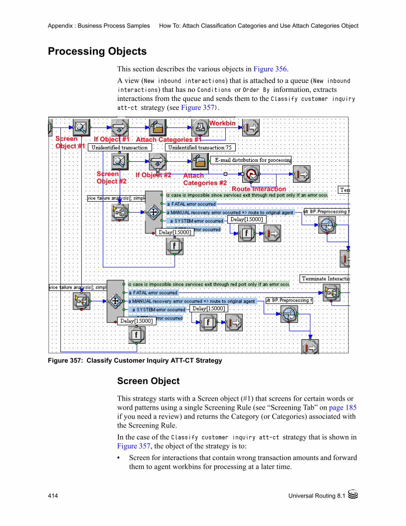
414 Universal Routing 8.1
Appendix : Business Process Samples How To: Attach Classification Categories and Use Attach Categories Object
Processing Objects
This section describes the various objects in Figure 356.
A view (New inbound interactions) that is attached to a queue (New inbound interactions) that has no Conditions or Order By information, extracts interactions from the queue and sends them to the Classify customer inquiry att-ct strategy (see Figure 357).
Figure 357: Classify Customer Inquiry ATT-CT Strategy
Screen Object
This strategy starts with a Screen object (#1) that screens for certain words or word patterns using a single Screening Rule (see “Screening Tab” on page 185 if you need a review) and returns the Category (or Categories) associated with the Screening Rule.
In the case of the Classify customer inquiry att-ct strategy that is shown in Figure 357, the object of the strategy is to:
• Screen for interactions that contain wrong transaction amounts and forward them to agent workbins for processing at a later time.
ScreenObject #1
ScreenObject #2
If Object #1 Attach Categories #1
Workbin
If Object #2 AttachCategories #2
Route Interaction
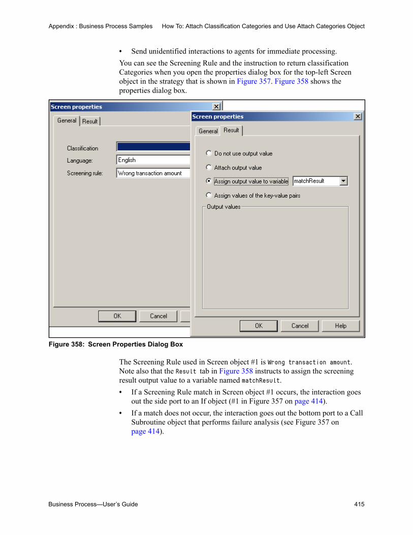
Business Process—User’s Guide 415
Appendix : Business Process Samples How To: Attach Classification Categories and Use Attach Categories Object
• Send unidentified interactions to agents for immediate processing.
You can see the Screening Rule and the instruction to return classification Categories when you open the properties dialog box for the top-left Screen object in the strategy that is shown in Figure 357. Figure 358 shows the properties dialog box.
Figure 358: Screen Properties Dialog Box
The Screening Rule used in Screen object #1 is Wrong transaction amount. Note also that the Result tab in Figure 358 instructs to assign the screening result output value to a variable named matchResult.
• If a Screening Rule match in Screen object #1 occurs, the interaction goes out the side port to an If object (#1 in Figure 357 on page 414).
• If a match does not occur, the interaction goes out the bottom port to a Call Subroutine object that performs failure analysis (see Figure 357 on page 414).
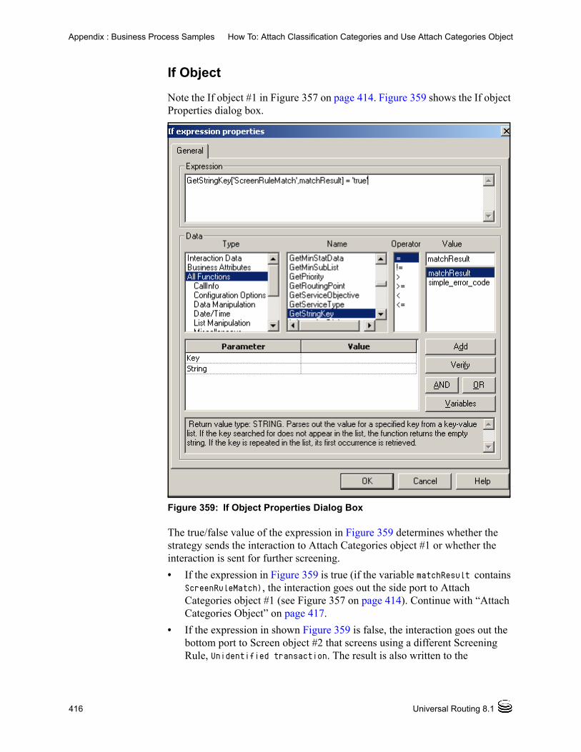
416 Universal Routing 8.1
Appendix : Business Process Samples How To: Attach Classification Categories and Use Attach Categories Object
If Object
Note the If object #1 in Figure 357 on page 414. Figure 359 shows the If object Properties dialog box.
Figure 359: If Object Properties Dialog Box
The true/false value of the expression in Figure 359 determines whether the strategy sends the interaction to Attach Categories object #1 or whether the interaction is sent for further screening.
• If the expression in Figure 359 is true (if the variable matchResult contains ScreenRuleMatch), the interaction goes out the side port to Attach Categories object #1 (see Figure 357 on page 414). Continue with “Attach Categories Object” on page 417.
• If the expression in shown Figure 359 is false, the interaction goes out the bottom port to Screen object #2 that screens using a different Screening Rule, Unidentified transaction. The result is also written to the

Business Process—User’s Guide 417
Appendix : Business Process Samples How To: Attach Classification Categories and Use Attach Categories Object
matchResult variable. The interaction goes out the side port to If object #2, whose properties dialog box appears the same as in Figure 359. Again, if the expression in If object #2 is true, the interaction goes out the side port to the Attach Categories object #2 (see Figure 357 on page 414).
Attach Categories Object
Figure 360 shows the Properties dialog boxes for Attach Categories object #1 and #2 in the Classify customer inquiry att-ct strategy that is shown in Figure 357 on page 414.
Figure 360: Attach Categories Properties Dialog Box
Attach Categories object #1 is used when initial screening indicates that the transaction contains an error (Wrong transaction amount Screening Rule match). The Screening Rule identifier is attached to the interaction, which then goes out the side port to a Workbin object for handling by a member of an Agent Group (E-mail distribution in Figure 356 on page 413). Figure 361 shows the Workbin Properties dialog box.
Attach Categories #1 Attach Categories #2

418 Universal Routing 8.1
Appendix : Business Process Samples How To: Attach Classification Categories and Use Attach Categories Object
Figure 361: Workbin Properties Dialog Box
Attach Categories Properties object #2 in Figure 360 on page 417 is used when evaluation of the expression in If object #2 indicates that the interaction is an unidentified one or contains an error. In this case, the interaction goes out the side port to a Route Interaction object (see Figure 357 on page 414). Figure 362 shows both tabs in the object properties dialog box for the Route Interaction object.
Figure 362: Route Interaction Properties Dialog Box
In the business process that is shown in Figure 356 on page 413, you can see the following objects: E-mail distribution for processing, Stop, and E-mails for QA review.
The following objects in Figure 356 on page 413 are the result of error handling:
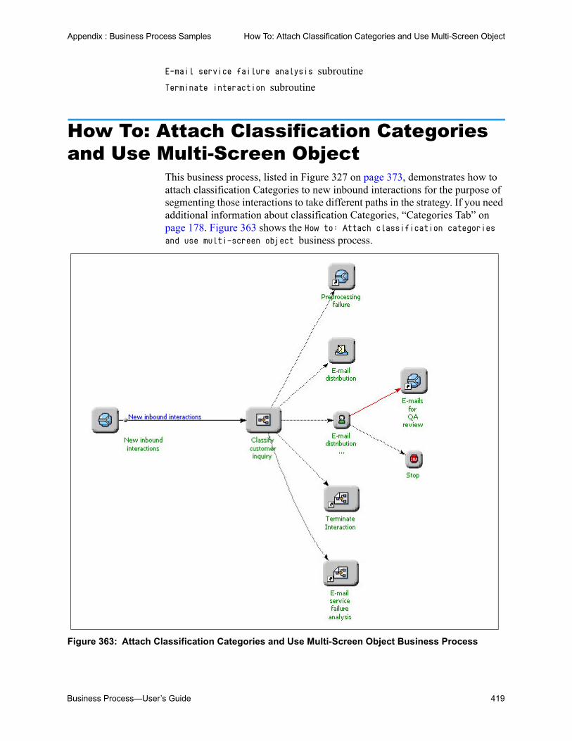
Business Process—User’s Guide 419
Appendix : Business Process Samples How To: Attach Classification Categories and Use Multi-Screen Object
E-mail service failure analysis subroutine
Terminate interaction subroutine
How To: Attach Classification Categories and Use Multi-Screen Object
This business process, listed in Figure 327 on page 373, demonstrates how to attach classification Categories to new inbound interactions for the purpose of segmenting those interactions to take different paths in the strategy. If you need additional information about classification Categories, “Categories Tab” on page 178. Figure 363 shows the How to: Attach classification categories and use multi-screen object business process.
Figure 363: Attach Classification Categories and Use Multi-Screen Object Business Process

420 Universal Routing 8.1
Appendix : Business Process Samples How To: Attach Classification Categories and Use Multi-Screen Object
Processing Objects
This section describes the various objects in Figure 363 on page 419.
A view (New inbound interactions) that is attached to a queue (New inbound interactions) that has no Conditions or Order By information, extracts interactions from the queue and sends them to the Classify customer inquiry strategy (see Figure 364).
Figure 364: Classify Customer Inquiry Strategy
Multi-Screen Object
This strategy starts with Multi-Screen object that screens for certain words or word patterns using multiple Screening Rules and returns the Categories associated with the Screening Rule.
Note: Compare the strategy in Figure 364, which uses the Multi-Screen object, with the Classify customer inquiry att-ct strategy that is shown in Figure 357 on page 414, which uses the Screen object. Complexity and the amount of byte code is reduced with the Multi-Screen object because Multi-Screen handles multiple rules and does not require a conditional test after each screening.
You can see the Screening Rules used and instruction to return classification Categories when you open the Multi-Screen object properties dialog box (see Figure 365).
Multi-Screen ScreenSegmentationObject
Object
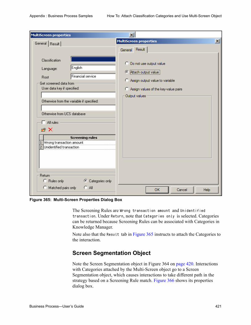
Business Process—User’s Guide 421
Appendix : Business Process Samples How To: Attach Classification Categories and Use Multi-Screen Object
Figure 365: Multi-Screen Properties Dialog Box
The Screening Rules are Wrong transaction amount and Unidentified transaction. Under Return, note that Categories only is selected. Categories can be returned because Screening Rules can be associated with Categories in Knowledge Manager.
Note also that the Result tab in Figure 365 instructs to attach the Categories to the interaction.
Screen Segmentation Object
Note the Screen Segmentation object in Figure 364 on page 420. Interactions with Categories attached by the Multi-Screen object go to a Screen Segmentation object, which causes interactions to take different path in the strategy based on a Screening Rule match. Figure 366 shows its properties dialog box.

422 Universal Routing 8.1
Appendix : Business Process Samples How To: Attach Classification Categories and Use Multi-Screen Object
Figure 366: Screen Segmentation Properties Dialog Box
Each segment in the Screen Segmentation properties dialog box generates its own output port in the strategy in Figure 364 on page 420.
• Interactions screened as Unidentified transaction (needing an agent response instead of a Standard Response) go a Workbin object. This is represented as the E-mail distribution Workbin strategy-linked node in Figure 363 on page 419.
Figure 367 on page 423 shows the various tabs in the Workbin properties dialog box.

Business Process—User’s Guide 423
Appendix : Business Process Samples How To: Attach Classification Categories and Use Multi-Screen Object
Figure 367: Workbin Properties Dialog Box
In the Target Selection tab, an Agent Group workbin named E-mail Distribution is selected. This is where the customer’s e-mail will reside while a response is constructed.
In the Interaction Queue tab, under Queue for New Interaction, the selection is E-mails for QA review found in the Default BP business process. This is where the agent will place the new interaction (e-mail response to customer) so it can be checked by QA prior to sending. This is represented by the E-mails failed QA strategy-linked queue node in Figure 363 on page 419.
The Genesys predefined Stop Processing(_STOP_) queue is represented by the Stop strategy-linked node in Figure 363 on page 419. It indicates a notification to Interaction Server that processing of the existing interaction has stopped.
• Interactions screened as containing Wrong transaction amount go to a Route Interaction object.
Figure 368 shows its properties dialog box.

424 Universal Routing 8.1
Appendix : Business Process Samples How To: Attach Classification Categories and Use Multi-Screen Object
Figure 368: Route Interaction Properties Dialog Box
In the Target Selection tab, an Agent Group named E-mail Distribution is selected. This target is also represented as the E-mail distribution strategy-linked node in Figure 363 on page 419.
In the Interaction Queue tab, under Queue for New Interaction, the selection is E-mails failed QA. This is the same queue used by the Workbin object (see Figure 367 on page 423). This is where the agent will place a new interaction (e-mail response to customer) so it can be checked by QA prior to sending. This is also represented by the E-mails failed QA strategy-linked queue node in Figure 363 on page 419.
The Genesys predefined Stop Processing(_STOP_) queue is represented by the Stop strategy-linked node in Figure 363 on page 419. It indicates a notification to Interaction Server that processing of the existing interaction has stopped.
Business Process—User’s Guide 425
Appendix : Business Process Samples How To: Conduct a Survey by Using Email
Error Handling
The following objects in Figure 363 on page 419 are the result of error handling:
E-mail service failure analysis subroutine
Terminate interaction subroutine
How To: Conduct a Survey by Using EmailThis business process demonstrates how a call center offers satisfaction surveys to their customers through outbound email or after a chat session. The survey can be sent to customers in a separate window after the chat has ended or sent by the agent as a link.
The survey results are stored as:
• A transcript under the parent chat interaction.
• Attached data to the parent chat interaction (enables reports to be run).
• A parent interaction to the original email
The email or chat survey implementation consists of the ASP/JSP pages on a web site and a business process to handle flow control of the survey.
The script on a Java Server Page (JSP) or Active Server Page (ASP) collects the submitted data and all parameters from the original link, creates the interaction, and sends it to the Interaction Server. Interaction Server then sends this interaction to the business process and an interaction is created within UCS by the business process strategy. Finally, the UCS stores the data in its database and can viewed in the contact’s historical data by using Genesys Application Desktop. Figure 369 on page 426 demonstrates the business process flow.
For more information about Interaction Server, see the eServices (Multimedia) 8.0 Deployment Guide.

426 Universal Routing 8.1
Appendix : Business Process Samples How To: Conduct a Survey by Using Email
Figure 369: Email Survey Business Process Strategies
Applicable Strategies
The business process that is used to process the original email and send the auto-response to the customer consists of three strategies, with a fourth strategy to handle the submission of surveys after the customer fills out the form (to Interaction Server from the web). The strategies are described in the following sections, where the s4e prefix (meaning survey for email) is used in all of the views, strategies and subroutines.
s4e_inbound_strategy
This strategy handles incoming email and distributes them among any available agents. It stops the original interaction (incoming email) and sends the agent's reply to the outbound queue. See Figure 370 on page 427.

Business Process—User’s Guide 427
Appendix : Business Process Samples How To: Conduct a Survey by Using Email
Figure 370: Route Interaction Properties
s4e_outbound_strategy
This strategy handles outgoing email, generates the standard response that contains the hard-coded link to the survey application, and passes the required parameters by using this link. See Figure 371 on page 428.

428 Universal Routing 8.1
Appendix : Business Process Samples How To: Conduct a Survey by Using Email
Figure 371: Create Email Out Properties
s4e_survey_email_strategy
This strategy sends the outbound email with a survey link. See Figure 372.
Figure 372: Strategy to Send Outbound Email
s4e_survey_strategy
This strategy handles the submission of surveys after customer has completed the form. The form is submitted to Interaction Server from the web. It is used

Business Process—User’s Guide 429
Appendix : Business Process Samples How To: Conduct a Survey by Using Email
to create the interaction in UCS and associate this interaction with the customer and parent interaction if one exists. See Figure 373.
Figure 373: Create Interaction Properties
Deploying the Email Survey Business Process
The following steps are required to deploy the Email survey business process:
1. Send the business process that is used to process the incoming email to the IRD.
2. In the Knowledge Manager application, configure a standard response.
3. In Configuration Server, add a new survey media type to the tenant.
4. In Tenant > Business Attributes > E-mail Accounts > Attribute Values, add a new Survey invitation element. Populate this element as follows:
a. On the Annex tab, create the general section
b. Add the address option with the survey_invitation value.
For more information about Knowledge Manager, see the eServices (Multimedia) 8.0 Deployment Guide.

430 Universal Routing 8.1
Appendix : Business Process Samples How To: Get Credit Card Number From the E-mail
Customizing the Business Process Configuration Options
Depending on your configuration, you might want to manually change some of the configuration options inside the strategy according to your business needs. After the business process is deployed, the options in Table 32 can be changed.
How To: Get Credit Card Number From the E-mail
This business process, which is listed in Figure 327 on page 373, demonstrates how to screen an interaction for credit card information.
• If the customer paid by credit card, the interaction is written to a queue for those types of interactions.
• If the customer did not pay by credit card, the interaction is written to a different queue.
Figure 374 shows the How to: Get Credit Card Number From the E-mail business process.
Table 32: Email Survey BP Configuration Options That Can be Changed
Element name Property name Default value
s4e_inbound_strategy
Route interaction Queue for new interaction
Survey For Email BP.s4e_outbound_email(s4e_outbound_email)
Agent Group E-mail distribution for processing
s4e_inbound_strategy
Create email output Output queue Survey For Email BP.s4e_survey_email(s4e_survey_email)
From Survey invitation
s4e_survey_strategy
Create interaction User Data Key survey_answer_Text

Business Process—User’s Guide 431
Appendix : Business Process Samples How To: Get Credit Card Number From the E-mail
Figure 374: Get Credit Card Number From the E-mail Business Process
If you need a review of screening, see “Screening Tab” on page 185.
Processing Objects
This section describes the various objects in Figure 374.
A view (Submit for credit card number for screening) that has no Conditions or Order By information (see Table 24 on page 273) extracts interactions from Inbound e-mail queue and sends them to the Screen e-mail for credit card numbers strategy (see Figure 375).
Figure 375: Screen E-mail for Credit Card Numbers Strategy
This strategy starts with the Multi-Screen object that screens for certain words or word patterns using multiple Screening Rules. It then returns the Categories (see page 178) associated with Screening Rules that matched.

432 Universal Routing 8.1
Appendix : Business Process Samples How To: Get Credit Card Number From the E-mail
Figure 376 shows the General and Result tab in the properties dialog box for the Multi-Screen object.
Figure 376: Multi-Screen Properties Dialog Box
The name of the Screening Rule is Credit card number. (If the Screening Rule does not display, see “Properties Dialog Boxes for Strategy Objects” on page 373.) Under Return, note that Matched pairs only is selected. This returns pairs consisting of a screening rule identifier and the specific string of words in the interaction that matches the screening rule. The Result tab in Figure 376 instructs to attach the Categories to the interaction.
Screen Segmentation Object
The next object in the strategy that is shown in Figure 375 on page 431 is a Screen Segmentation object. Interactions with Categories attached by the Multi-Screen object go to a Screen Segmentation object. It causes interactions to take different path in the strategy based on whether a Screening Rule match occurred. Figure 377 shows its properties dialog box.

Business Process—User’s Guide 433
Appendix : Business Process Samples How To: Get Credit Card Number From the E-mail
Figure 377: Screen Segmentation Properties Dialog Box
As shown in Figure 374 on page 431:
• Interactions matching the Credit card number Screening Rule go out the side port to a Queue Interaction object that specifies an interaction queue that is called Paid with credit card.
• Interactions that do not match the Credit card number Screening Rule go to another Queue Interaction object that specifies an interaction queue that is called Non-credit card payment.
Figure 378 shows the properties dialog box for each Queue Interaction object after clicking the down arrows to show all queues including the selected queues.

434 Universal Routing 8.1
Appendix : Business Process Samples How To: Handle Fax Interactions
Figure 378: Queue Interaction Properties Dialog Boxes
The names of both interaction queues are reflected in the business process that is shown in Figure 374 on page 431.
How To: Handle Fax InteractionsThis business process, listed in Figure 327 on page 373, demonstrates how screening can work with various medias, such as fax.
• Interactions that match a Screening Rule trigger an automatic response and/or redirecting or forwarding to other agents.
• If an interaction fails the screening, this means the interaction cannot be processed automatically and requires an agent’s attention. An acknowledgement e-mail is generated and the interaction goes to a queue for further processing.
Figure 379 on page 435 shows the How to: Handle Fax Interactions business process.

Business Process—User’s Guide 435
Appendix : Business Process Samples How To: Handle Fax Interactions
Figure 379: Handle Fax Interactions Business Process
Processing Objects
This section describes the various objects in Figure 379.
A view (Select all interactions) that has no Conditions or Order By information (see Table 24 on page 273) extracts interactions from the Inbound fax Interactions queue and sends them to the strategy, Preliminary fax screening (see Figure 380).
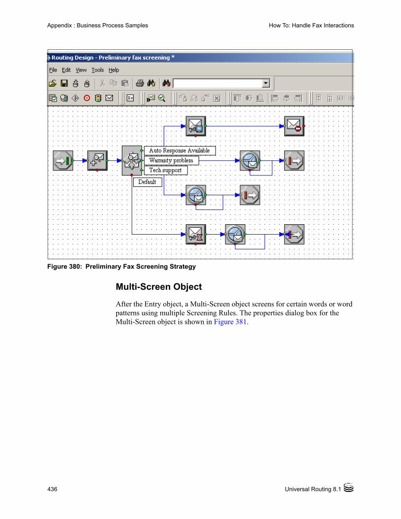
436 Universal Routing 8.1
Appendix : Business Process Samples How To: Handle Fax Interactions
Figure 380: Preliminary Fax Screening Strategy
Multi-Screen Object
After the Entry object, a Multi-Screen object screens for certain words or word patterns using multiple Screening Rules. The properties dialog box for the Multi-Screen object is shown in Figure 381.

Business Process—User’s Guide 437
Appendix : Business Process Samples How To: Handle Fax Interactions
Figure 381: Multi-Screen Properties Dialog Box
The Screening Rules are Auto Response Available, Warranty problem, and Tech support.
Under Return, Rules only is selected, which returns only the Screening Rule identifier when a match is found.
The Result tab instructs to attach the Screening Rule identifier to the interaction.
Screen Segmentation Object
After the Multi-Screen object, the next object in the strategy that is shown in Figure 380 on page 436 is a Screen Segmentation object. Interactions take different paths in the strategy based on the Screening Rule that was matched. Figure 382 shows its properties dialog box.

438 Universal Routing 8.1
Appendix : Business Process Samples How To: Handle Fax Interactions
Figure 382: Screen Segmentation Properties Dialog Box
Each segment in the Screen Segmentation properties dialog box generates its own output port in the strategy (see Figure 380 on page 436).
Autoresponse Object
Interactions matching the Screen Rule Auto Response Available go an Autoresponse object that uses Customer Support phone text from a Standard Response Library to create an automatic response (see Figure 383).
Figure 383: Send Automated Response Properties

Business Process—User’s Guide 439
Appendix : Business Process Samples How To: Handle Fax Interactions
Under Operation Mode in Figure 383 on page 438, Open Media is selected.
After the Autoresponse object in the strategy in Figure 380 on page 436, a Stop Interaction object notifies Interaction Server that processing for this particular interaction has stopped and supplies a reason code.
Warranty ProblemSegment
Interactions in Figure 380 on page 436 with a screening result of Warranty problem go to an Queue Interaction object that specifies an interaction queue that is called Forward interaction (see Figure 384).
Figure 384: Queue Interaction Properties Dialog Box
Tech SupportSegment
Interactions in Figure 380 on page 436 with a screening result of Tech support go to an Queue Interaction object that specifies an interaction queue that is called Redirect Interaction (see Figure 385).
Figure 385: Queue Interaction Properties Dialog Boxes
All of the above interactions are faxes, which can be processed automatically.
Processing byAgents
Interactions not matching any of the previous Screening Rules cannot be processed automatically. These interactions go out the bottom port of the Multi-Screen object to an Acknowledgement object (see Figure 386).

440 Universal Routing 8.1
Appendix : Business Process Samples How To: Handle Fax Interactions
Figure 386: Acknowledgment Receipt Properties Dialog Box
After an acknowledgment e-mail is generated, the interaction is placed in a queue (Processing by Agents) for processing by agents (see Figure 387).
Figure 387: Queue Interaction Properties Dialog Box

Business Process—User’s Guide 441
Appendix : Business Process Samples How To: Identify Contact and Create Interaction in UCS
How To: Identify Contact and Create Interaction in UCS
This business process, listed in Figure 327 on page 373, demonstrates how to process an inbound interactions queue based on whether a customer contact exists or does not exist in the Universal Contact Server (UCS) Database.
The strategy checks to see if this is an existing contact. If the contact exists, the strategy creates an interaction for that customer in the UCS Database. If the contact does not exist, processing continues without the creation of an interaction in the UCS Database. Figure 388 shows the business process.
Figure 388: Identify Contact, Create Interaction in UCS Business Process
Processing Objects
This section describes the various objects in Figure 388.
A view (All inbound interactions), that has no Conditions or Order By information, extracts interactions from an interaction queue that is called Inbound Interactions and submits them to the Identify Contact and create interaction strategy (see Figure 389).

442 Universal Routing 8.1
Appendix : Business Process Samples How To: Identify Contact and Create Interaction in UCS
Figure 389: Identify Contact and Create Interaction Strategy
The second object in the strategy is Identify Contact (see page 204). Figure 390 shows both tabs of its properties dialog box.
Figure 390: Identify Contact Properties Dialog Box
Note: The Contact server field in Figure 380 is blank. If you do not specify a Contact server, URS finds all available servers and selects based on load balancing.
The Result tab instructs to write the content of an Interaction Data field, existingContact, to a variable, also called existingContact.
• If there is no existingContact field or if it is empty, the interaction goes out the bottom port to the default destination, an option configured in the URS Application object.
• If the existingContact variable contains a value, the interaction goes out the side port to an If object (see Figure 391 on page 443), which is the third object in the strategy in Figure 389.

Business Process—User’s Guide 443
Appendix : Business Process Samples How To: Identify Contact and Create Interaction in UCS
Figure 391: If Object Properties Dialog box
The If object calls a function called GetStringKey. This function parses out the value for a specified key. If the searched-for key does not appear in the list, the function returns an empty string.
The first parameter in the function call is the key, which is NumberOfContactsFound. The second parameter is the variable to contain the Interaction Data, which is existingContact.
• If the expression is false (existingContact=0), if the interaction is not from an existing contact, it goes out the bottom port to a Queue Interaction object specifying a queue for new contacts. Figure 392 shows the Queue Interaction properties dialog box after clicking the down arrow to show the selected queue.

444 Universal Routing 8.1
Appendix : Business Process Samples How To: Identify Contact and Create Interaction in UCS
Figure 392: Queue Interaction Properties Dialog Box
• If the expression in Figure 391 on page 443 is true (existingContact=1), if the interaction is from an existing contact, it goes out the side port to a Create Interaction object, which is the fourth object in the strategy in Figure 389 on page 442. Figure 393 shows the properties dialog box.
Figure 393: Create Interaction Properties Dialog Box

Business Process—User’s Guide 445
Appendix : Business Process Samples How To: Place the Interaction Into the Workbin
Again, the Contact server field in Figure 380 is blank. If you do not specify a Contact server, URS finds all available servers and selects based on load balancing.
• If record creation is successful; the interaction goes out the side port to a queue for interactions for existing contacts. Figure 394 shows the Queue Interaction Properties dialog box after clicking the down arrow to show the selected queue.
Figure 394: Queue Interaction Properties Dialog Box
• If record creation is unsuccessful, the interaction goes out the bottom port to the default destination.
How To: Place the Interaction Into the Workbin
This business process, listed in Figure 327 on page 373, demonstrates how to route an interaction to the agent that originally handled it. If the original agent is not immediately available, the strategy places the interaction in the original agent’s workbin for later handling.

446 Universal Routing 8.1
Appendix : Business Process Samples How To: Place the Interaction Into the Workbin
Note: If you need a review of workbins, see page 33 of this guide.
Figure 395 shows the Place the Interaction Into the Workbin business process.
Figure 395: Place Interaction Into Workbin Business Process
Processing Objects
This section describes the various objects in Figure 395.
A view (E-mails to route) that has no Conditions or Order by Information attached to a queue (E-mails to route to original agent) extracts interactions and sends them to the strategy Place Interaction into the workbin (see Figure 396).
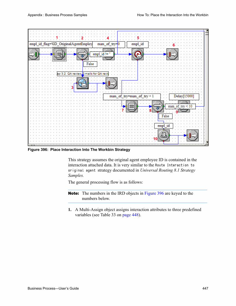
Business Process—User’s Guide 447
Appendix : Business Process Samples How To: Place the Interaction Into the Workbin
Figure 396: Place Interaction Into The Workbin Strategy
This strategy assumes the original agent employee ID is contained in the interaction attached data. It is very similar to the Route Interaction to original agent strategy documented in Universal Routing 8.1 Strategy Samples.
The general processing flow is as follows:
Note: The numbers in the IRD objects in Figure 396 are keyed to the numbers below.
1. A Multi-Assign object assigns interaction attributes to three predefined variables (see Table 33 on page 448).
1 2
3
4 5
6
7 8 9
10

448 Universal Routing 8.1
Appendix : Business Process Samples How To: Place the Interaction Into the Workbin
2. After setting the variables, an If object initializes the empl_id variable so it does not contain a value.
3. If the expression in is true (if empl_id does not contain a value indicating there is no original agent), the e-mail, goes out the bottom port to a Queue E-mail object specifying the queue E-mails for QA review (strategy-linked node in Figure 395 on page 446. This is used for a collaboration reply e-mail from one agent to another.
4. If the expression is false (if there is an original agent), the e-mail goes out the side port of the If object to an Assign object, which sets a counter (variable num_of_try) to zero.
5. A Route Interaction object attempts to route the interaction to the original agent contained in the empl_id variable. This target is represented by the Dynamic target strategy-linked node in Figure 395 on page 446.
6. If the routing is successful, the strategy has achieved its goal and an Exit object is connected to the side port of the Route Interaction object.
7. If the agent cannot accept the interaction for some reason, the e-mail goes out the bottom port of the Route Interaction object to an Assign object, which increments the num_of_try counter.
8. The e-mail goes out the side port of the Assign object to an If object, which is used to decide whether the number of processing cycles to determine the original agent is 10 or less.
9. If the expression is true (number of tries to route to the original agent is less than 10), the interaction goes out the side port of the If object to a Function object to delay strategy execution.
Table 33: Place Interaction Into the Workbin Predefined Variables
Variable Description
empl_id. The Udata function attempts to get a value from the attached data key empl_id_flag and write it to this variable. If this key contains a value, it indicates that there is an original agent for routing.
empl_id_flag. The original agent employee ID number. GD_OriginalAgentEmployeeID is an attached data key that may contain the identifier.
num_of_tries is initialized to 0. It functions as a counter used to control the number of tries the strategy makes to route to the original agent.

Business Process—User’s Guide 449
Appendix : Business Process Samples How To: Screen Multiple Rules and Use Screening Switch
Once the delay is established, the e-mail goes out the side port of the Function object back to the Route Interaction object to attempt to route to the original agent.
10. If the expression is false (number of tries is 10 or greater), the e-mail goes out the bottom port of the If object to a Workbin object (Workbin for original agent strategy-linked node in Figure 395 on page 446). This workbin is associated with the agent contained in the empl_id variable.
How To: Screen Multiple Rules and Use Screening Switch
This business process, listed in Figure 327 on page 373, demonstrates how to screen incoming interactions using multiple Screening Rules by using the Multi-Screen object.
Note: Multi-Screen differs from Screen in that it supplies additional return options: Screening Rules only, classification Categories only, matched pairs only, or all three. It also does not require a conditional test to determine whether a match occurred.
The strategy also demonstrates how to segment interactions to take different paths based on Screening Rules.
Figure 397 shows the Screen Multiple Rules and Use Screening Switch business process.

450 Universal Routing 8.1
Appendix : Business Process Samples How To: Screen Multiple Rules and Use Screening Switch
Figure 397: Screen Multiple Rules and Use Screening Switch BP

Business Process—User’s Guide 451
Appendix : Business Process Samples How To: Screen Multiple Rules and Use Screening Switch
Processing Objects
This section describes the various objects in Figure 397.
A view (Inbound e-mail postprocessing) that has no Conditions or Order by information attached to a queue (Inbound e-mail postprocessing) extracts interactions and sends them to the strategy Preliminary e-mail screening ms. Figure 398 shows the top part of the strategy.
Figure 398: Preliminary E-mail Screening MS Strategy
Note: “MS” at the end of the strategy name stands for “Multi-Screen.”
1. This strategy uses the Multi-Screen object and three different Screening Rules (Auto Response Available, Warranty Problem, and Tech Support) to screen inbound interactions for words or word patterns.
1. Multi-ScreenObject
2. ScreenSegmentationObject
3. AutoresponseObject
4. AcknowledgementObject

452 Universal Routing 8.1
Appendix : Business Process Samples How To: Screen Multiple Rules and Use Screening Switch
2. A Screen Segmentation object connected to the green output port of the Multi-Screen object causes different screening results to take different paths in the strategy.
The purpose of the initial screening is determine whether the e-mail can be responded to with a Standard Response.
3. If yes, an Autoresponse object generates a Standard Response (see the Autoresponse strategy-linked node in Figure 397 on page 450). A Stop object (see Figure 333 on page 378) notifies Interaction Server that processing of this interaction is finished (see Stop strategy-linked node in Figure 397 on page 450).
If a Standard Response cannot be used, a second screening determines whether the e-mail contains text that indicating it is from a customer with a warranty problem and therefore should be placed in a queue for forwarding. If yes, the e-mail is placed in that queue (see the Forward e-mails queue in Figure 397 on page 450). A Stop object (see Figure 333 on page 378) notifies Interaction Server that processing of this interaction is finished (see Stop strategy-linked node in Figure 397 on page 450).
If the second screening indicates a warranty problem is not involved, the e-mail goes through a third screening to determine if it contains text indicating it is from a customer with a technical support problem and therefore should be placed in a queue for redirecting. If yes, the e-mail is placed in a queue for redirecting (see the Redirect e-mails queue in Figure 397 on page 450). A Stop object notifies Interaction Server that processing of this interaction is finished (see Stop strategy-linked node in Figure 397 on page 450).
4. If the third screening does not produce results, an Acknowledgement object generates an acknowledgement Standard Response. The e-mail then goes to a queue for processing by agents (see the E-mails for processing by agents queue in Figure 397 on page 450).
Error Handling
The following objects in Figure 397 on page 450 are the result of error handling:
Preprocessing failure queue
E-mail service failure analysis subroutine
Terminate interaction subroutine
Termination failure queue
Multi-Screen Versus Screen
This strategy is the functional equivalent of the Preliminary e-mail screening strategy that is discussed in Universal Routing 8.1 Strategy Samples.

Business Process—User’s Guide 453
Appendix : Business Process Samples How To: Screen Multiple Rules and Use Screening Switch
The difference between the two is as follows:
• Preliminary e-mail screening uses three separate Screen objects. After each screen object, the strategy uses an If object and performs a conditional test to determine whether a screening rule match occurred. This adds a level of complexity and generates additional code.
Figure 399 shows the three Screen objects and If objects in the strategy.
Figure 399: Multi-Screen Object Properties Dialog Box
• Compare the strategy in Figure 399 with the strategy Preliminary e-mail screening ms, shown in Figure 398 on page 451, which uses the Multi-Screen object. Complexity and the amount of byte code is reduced because a single object handles multiple rules and does not require a conditional test after each screening. Figure 400 on page 454 shows the properties dialog box for the Multi-Screen object in Preliminary e-mail screening ms.
Screen Object #1
Screen Object #2
Screen Object #3
If Object for conditional test
If object for conditional test

454 Universal Routing 8.1
Appendix : Business Process Samples How To: Screen Multiple Rules and Use Screening Switch
Figure 400: Screen Object Properties Dialog Box (Accepts One Rule)
Figure 401 shows the properties dialog box for the Screen Segmentation object attached to the Multi-Screen object.

Business Process—User’s Guide 455
Appendix : Business Process Samples How To: Screen Multiple Rules and Use Screening Switch
Figure 401: Screen Segmentation Properties Dialog Box
Each segment in Figure 401 generates its own output port (see the Screen Segmentation object in Figure 398 on page 451).

456 Universal Routing 8.1
Appendix : Business Process Samples How To: Screen Multiple Rules and Use Screening Switch

Business Process—User’s Guide 457
Supplements
Related Documentation ResourcesThe following resources provide additional information that is relevant to this software. Consult these additional resources as necessary.
Universal Routing
• Interaction Routing Designer 8.1 Help, comprised of Routing Design Help and Interaction Workflow Design Help. The information contained in this help file duplicates some of the information contained in this guide, but presents it in a shorter, online format.
• Universal Routing 8.1 Reference Manual, which describes and defines routing strategies, IRD objects used in strategies, functions that can be called from strategies, Universal Routing Server and other server options, number translations, pegs, statistics used for routing decisions, and reporting on routing. You will want to consult this guide to get additional information about the IRD objects discussed in “Planning a Business Process” on page 195 of this book.
• Universal Routing 8.1 Deployment Guide. The first part of the guide provides information you will need to get started: A high-level overview of Universal Routing features and functions, including product architecture, system availability, redundancy information and deployment-planning. The second part of the guide provides instructions for deploying Universal Routing components, and describes how to start and stop these components once you have configured and installed them.
• Universal Routing 8.1 Strategy Samples, which simplifies strategy configuration for first-time users of the strategy development tool, Interaction Routing Designer. To achieve this goal, this document supplies examples of routing strategies that can be used as general guides during the design stage.
• Universal Routing 8.0 Routing Application Configuration Guide (previously Universal Routing 7.6 Routing Solutions Guide), which contains information about the various types of routing solutions that can

458 Universal Routing 8.1
Related Documentation Resources
be implemented, including skills-based routing, business-priority routing, share agent by service level agreement routing, and proactive routing. It also discusses Universal Routing support for a Genesys Instant Messaging Solution.
• Universal Routing 7.6 Cost-Based Routing Configuration Guide, which documents a solution where Universal Routing Server considers the cost of routing to a target, comprised of Infrastructure cost and/or Resource cost, as addition selection criteria when choosing the right target.
• Genesys 7.6 Proactive Routing Solution Guide, which documents a solution that enables you to proactively route outbound preview interactions to Genesys Agent Desktop, as well as to completely process Calling List and Do Not Call List records solely from the logic of a routing strategy without agent intervention.
eServices
• eServices (Multimedia) 8.0 Deployment Guide, which provides a high-level overview of features and functions of Genesys Multimedia with architecture information and deployment-planning materials. It also introduces you to some of the basic concepts and terminology used in this product.
• eServices (Multimedia) 8.0 User’s Guide, which provides overall information and recommendations on the use and operation of the Genesys Multimedia components.
• eServices (Multimedia) 8.0Reference Manual, which provides a reference listing of all configuration options and of Field Codes used in Standard Responses.
• eServices (Multimedia) 8.0 Knowledge Manager Help, which is an online guide to Knowledge Manager, the user interface for Genesys Knowledge Base. You use Knowledge Manager to create and manage the Category structure for Standard Responses, create and validate Field Codes, and to create and edit Screening Rules.
• “Multimedia Log Events” in Framework 8.0 Combined Log Events Help, which is a comprehensive list and description of all events that may be recorded in logs.
Genesys
• Genesys Technical Publications Glossary, which ships on the Genesys Documentation Library DVD and which provides a comprehensive list of the Genesys and computer-telephony integration (CTI) terminology and acronyms used in this document.

Business Process—User’s Guide 459
Related Documentation Resources
• Genesys Migration Guide, which ships on the Genesys Documentation Library DVD, and which provides documented migration strategies for Genesys product releases. Contact Genesys Technical Support for more information.
• Release Notes and Product Advisories for this product, which are available on the Genesys Technical Support website at http://genesyslab.com/support.
Information about supported hardware and third-party software is available on the Genesys Technical Support website in the following documents:
• Genesys Supported Operating Environment Reference Manual
• Genesys Supported Media Interfaces Reference Manual
Consult these additional resources as necessary:
• Genesys Hardware Sizing Guide, which provides information about Genesys hardware sizing guidelines.
• Genesys Interoperability Guide, which provides information about the compatibility of Genesys products with various Configuration Layer Environments; Interoperability of Reporting Templates and Solutions; and Gplus Adapters Interoperability.
• Genesys Licensing Guide, which introduces you to the concepts, terminology, and procedures relevant to the Genesys licensing system.
• Genesys Database Sizing Estimator 8.0 Worksheets, which provides a range of expected database sizes for various Genesys products.
For additional system-wide planning tools and information, see the release-specific listings of System Level Documents on the Genesys Technical Support website, accessible from the system level documents by release tab in the Knowledge Base Browse Documents Section.
Genesys product documentation is available on the:
• Genesys Technical Support website at http://genesyslab.com/support.
• Genesys Documentation Library DVD, which you can order by e-mail from Genesys Order Management at [email protected].

460 Universal Routing 8.1
Document Conventions
Document ConventionsThis document uses certain stylistic and typographical conventions—introduced here—that serve as shorthands for particular kinds of information.
Document Version Number
A version number appears at the bottom of the inside front cover of this document. Version numbers change as new information is added to this document. Here is a sample version number:
80fr_ref_06-2008_v8.0.001.00
You will need this number when you are talking with Genesys Technical Support about this product.
Screen Captures Used in This Document
Screen captures from the product graphical user interface (GUI), as used in this document, may sometimes contain minor spelling, capitalization, or grammatical errors. The text accompanying and explaining the screen captures corrects such errors except when such a correction would prevent you from installing, configuring, or successfully using the product. For example, if the name of an option contains a usage error, the name would be presented exactly as it appears in the product GUI; the error would not be corrected in any accompanying text.
Type Styles
Table 34 describes and illustrates the type conventions that are used in this document.
Table 34: Type Styles
Type Style Used For Examples
Italic • Document titles
• Emphasis
• Definitions of (or first references to) unfamiliar terms
• Mathematical variables
Also used to indicate placeholder text within code samples or commands, in the special case where angle brackets are a required part of the syntax (see the note about angle brackets on page 461).
Please consult the Genesys Migration Guide for more information.
Do not use this value for this option.
A customary and usual practice is one that is widely accepted and used within a particular industry or profession.
The formula, x +1 = 7 where x stands for . . .

Business Process—User’s Guide 461
Document Conventions
Monospace font
(Looks like teletype or typewriter text)
All programming identifiers and GUI elements. This convention includes:
• The names of directories, files, folders, configuration objects, paths, scripts, dialog boxes, options, fields, text and list boxes, operational modes, all buttons (including radio buttons), check boxes, commands, tabs, CTI events, and error messages.
• The values of options.
• Logical arguments and command syntax.
• Code samples.
Also used for any text that users must manually enter during a configuration or installation procedure, or on a command line.
Select the Show variables on screen check box.
In the Operand text box, enter your formula.
Click OK to exit the Properties dialog box.
T-Server distributes the error messages in EventError events.
If you select true for the inbound-bsns-calls option, all established inbound calls on a local agent are considered business calls.
Enter exit on the command line.
Square brackets ([ ])
A particular parameter or value that is optional within a logical argument, a command, or some programming syntax. That is, the presence of the parameter or value is not required to resolve the argument, command, or block of code. The user decides whether to include this optional information.
smcp_server -host [/flags]
Angle brackets (< >)
A placeholder for a value that the user must specify. This might be a DN or a port number specific to your enterprise.
Note: In some cases, angle brackets are required characters in code syntax (for example, in XML schemas). In these cases, italic text is used for placeholder values.
smcp_server -host <confighost>
Table 34: Type Styles (Continued)
Type Style Used For Examples

462 Universal Routing 8.1
Document Conventions
Business Process—User’s Guide 463
Index
Symbols[] (square brackets). . . . . . . . . . . . . . 461< > (angle brackets) . . . . . . . . . . . . . 461
AABC Simple BP . . . . . . . . . . . . . . . 374ABC Simple Chat BP. . . . . . . . . . . . . 379access permissions . . . . . . . . . . . . . 153Accounting for Labels . . . . . . . . . . . . 91accurate printing . . . . . . . . . . . . . . . 90Acknowledgement button . . . . . . . . . . 127Acknowledgement object. . . 125, 176, 185, 201Activate Strategy . . . . . . . . . . . . . . . 83active strategy loading . . . . . . . . . . . . 84Add Record object . . . . . . . . . . . . . . 211Add Record object button . . . . . . . . . . 128add strategy to Business Process . . . . . . 356agent
capacity rule assignment . . . . . . . . . 164configuration. . . . . . . . . . . . . .156, 161group . . . . . . . . . . . . . . 133, 156, 207routing target . . . . . . . . . . . . . . . 133strategy linked node . . . . . . . . . . . . . 36workbin . . . . . . . . . . . . . . . . . . 208
Allow Docking . . . . . . . . . . . . .95, 96, 97angle brackets . . . . . . . . . . . . . . . . 461Angle Snap . . . . . . . . . . . . . . . . . . 113ANI object . . . . . . . . . . . . . . . . . . 125Annex tab in Configuration Manager . . . . . 172Application
Configuration Manager login . . . . . . . 238IRD login dialog box . . . . . . . . . . . . . 59Knowledge Manager login. . . . . . . . . 224
Apply escalation procedure . . . . . . . . . 410Arrange Objects
Interaction Design view . . . . . . . . . . . 83arrange objects. . . . . . . . . . . . . . . . 71Arranging Options tab . . . . . . . . . . . . 91arrow
Queue object . . . . . . . . . . . . . . . . 28Strategy object . . . . . . . . . . . . . . . 30Workbin node . . . . . . . . . . . . . . . . 37
asl . . . . . . . . . . . . . . . . . . . . . . .84Assign object . . . . . . . . 126, 133, 209, 343Attach Categories button . . . . . . . . . . 127Attach Categories object. . . . . . . . 180, 202Attach classification Categories sample . . . 410attached data . . . . . . . . . . . . . 126, 292Attributes
definition . . . . . . . . . . . . . . . . . 118interactions . . . . . . . . . . . . . . . . 216view . . . . . . . . . . . . . . . . . . 112, 273
audience, for document . . . . . . . . . . . .16Autoresponse button. . . . . . . . . . . . . 127Autoresponse object . . . . . 125, 176, 185, 202
Bbackup strategy . . . . . . . . . . . . . . . 140black connector line in workflow viewer . 38, 305brackets
angle . . . . . . . . . . . . . . . . . . . 461square. . . . . . . . . . . . . . . . . . . 461
Business Attributes . . . . . . . . . . 208, 209definition . . . . . . . . . . . . . . . . . 161origin . . . . . . . . . . . . . . . . . . . 244
Business Processadd strategy. . . . . . . . . . . . . . . . 356Attach Classification Categories . . . 413, 419cannot copy . . . . . . . . . . . . . . . . . 78connecting with queues . . . . . . . . . . 199creating . . . . . . . . . . . . . . . . . . 247definition . . . . . . . . . . . . . . . . . . 21exporting . . . . . . . . . . . . . . . . . 307flow diagram . . . . . . . . . . . . . . . . 42GUI . . . . . . . . . . . . . . . . . . . . . 57importing . . . . . . . . . . . . . . . . . 310List view. . . . . . . . . . . . . . . . . . 104Locate command . . . . . . . . . . . . . . 38menu . . . . . . . . . . . . . . . . . . . . 82
Index
464 Universal Routing 8.1
nodes . . . . . . . . . . . . . . . . . . . . 34object definitions. . . . . . . . . . . . . . . 27originating . . . . . . . . . . . . . . . . . . 28overview . . . . . . . . . . . . . . . . . . . 21planning . . . . . . . . . . . . . . . . . . 195printing. . . . . . . . . . . . . . . . . . . . 90printing large. . . . . . . . . . . . . . . . . 77samples . . . . . . . . . . . . . . . . 25, 369Script file. . . . . . . . . . . . . . . . . . 159shortcut menu . . . . . . . . . . . . . . . . 94strategy comparison . . . . . . . . . . . . . 44switching to another . . . . . . . . . . . . 252
Business Rulesdefinition . . . . . . . . . . . . . . . . . . 119view . . . . . . . . . . . . . . . . . . . . 112
Business segmentation object . . . . . . . . 125buttons for reusable objects . . . . . . . . . 116
Ccall flow
printing. . . . . . . . . . . . . . . . . 76, 108Call subroutine button . . . . . . . . . . . . 126Call Subroutine object . . . . . . .126, 209, 415Campaign . . . . . . . . . . . . . . . 203, 211Capacity Planning Wizard . . . . . . . . . . 165Capacity Rule assignment . . . . . . . . . . 164Categories . . . . . . . . . . 176, 202, 203, 208Change Password . . . . . . . . . . . . . . 110Change Tenant . . . . . . . . . . . . . . . . 114Chat Transcript button . . . . . . . . . . . . 127Chat Transcript object . . . . . . . . . 125, 202Check Integrity . . . . . . . . . . . . . 112, 354Check Interval (sec) . . . . . . . . . . 272, 287CIM (Customer Interaction Management)
Platform . . . . . . . . . . . . . .14, 15classification categories . . . 176, 178, 413, 419Classification Segmentation object. . . . . . 176Classification Server . . . . . . 50, 202, 203, 205Classify button . . . . . . . . . . . . . . . . 127Classify object . . . . . . . . . . . . . . . . 203Classify Segmentation object . . . . . 125, 208CollaborationReply . . . . . . . . . . . . . . 333color of connector . . . . . . . . . . . . . . 38Comment object . . . . . . . . . . . . 139, 340commenting on this document . . . . . . . . 17communication protocol . . . . . . . . . . . 53compile strategy . . . . . . . . . . . . . . . 353conceptual diagram . . . . . . . . . . . . . 24Condition tab for view . . . . . . . . . 216, 273conditions for extracting interactions . . . . . 29conduct an email survey using email. . . . . 425Configuration Database . . . . . . . . . . . 176Configuration Manager
login . . . . . . . . . . . . . . . . . . . . 237using. . . . . . . . . . . . . . . . . . . . 155
configuration order . . . . . . . . . . . . . . 217Configuration Server
port for CME . . . . . . . . . . . . . . . 238port for IRD . . . . . . . . . . . . . . . . . 59
Configuration Updates tab . . . . . . . . . . .72Contact Attributes . . . . . . . . . . . . . . 246Contact Server . . . . . . . . . . . . . . . . .22
empty in IRD properties. . . . . . . . 442, 445Content Analyzer . . . . . . . . . . . . . . .50conventions
in document . . . . . . . . . . . . . . . . 460type styles. . . . . . . . . . . . . . . . . 460
copyBusiness Process . . . . . . . . . . . . . . 78Routing Design view . . . . . . . . . . . 111
Create E-mail Out button . . . . . . . . . . 127Create E-mail Out object. . . . . . . . . . . 203Create Interaction button . . . . . . . . . . 127Create Interaction object. . . . . . . . . . . 203Create Notification button . . . . . . . . . . 127Create Notification object . . . . . . . . . . 203Create SMS button . . . . . . . . . . . . . 127Create SMS object. . . . . . . . . . . . . . 203Create SMS Out button . . . . . . . . . . . 129Create SMS Out object . . . . . . . . . . . 207curved lines . . . . . . . . . . . . . . . . . .27Custom Variables . . . . . . 175, 176, 218, 233Customer Segment . . . . . . . . . . . . . 163Customize IRD toolbars . . . . . . . . . . . 114cut copy paste in strategy . . . . . . . .111, 140
DData & Services objects . . . . . . 206, 207, 209database
Configuration . . . . . . . . . . . . . 176, 179expressions . . . . . . . . . . . . . . . . 292index . . . . . . . . . . . . . . . . . . . 292integrity . . . . . . . . . . . . . . . . 87, 354Universal Contact Server . . . . . . . 50, 179
Database Hints . . . . . . . . . . . . . . . 284Database Wizard . . . . . . . . . . . 124, 147Date object. . . . . . . . . . . . . . . . . . 125Day of the Week object . . . . . . . . . . . 125DB2 . . . . . . . . . . . . . . . . . . . . . 292deactivate routing strategy. . . . . . . . 85, 366default condition . . . . . . . . . . . . . . . 292default destination . . . . . . . . . . . . . . 442Default Font tab in Routing Design . . . . . 146default inbound queue . . . . . . . . . . . . .22default order . . . . . . . . . . . . . . . . . 292default skill level . . . . . . . . . . . . . . . 402Default strategy-building object . . . . . . . 125definition of Business Process. . . . . . . . .21Delete
Interaction Design view . . . . . . . . . . . 83
Index
Business Process—User’s Guide 465
strategy and reusable objects . . . . . . . 359Deployment View. . . . . . . . . . . . . . . 64Describe
queue . . . . . . . . . . . . . . . . . . . 261show strategy conditions . . . . . . . . . 340strategy . . . . . . . . . . . . . . . . . . 107synthetic queue . . . . . . . . . . . . . . 266workbin . . . . . . . . . . . . . . . . . . 295
Desktop interface. . . . . . . . . . . . . . . 282displaying GUI elements . . . . . . . . . . . 147Distribute Custom Event button . . . . . . . 127DNIS object . . . . . . . . . . . . . . . . . 125Do Not Call object . . . . . . . . . . . . . . 211Do Not Call object button. . . . . . . . . . . 128Docking. . . . . . . . . . . . . . . . .95, 96, 97document
audience. . . . . . . . . . . . . . . . . . . 16change history . . . . . . . . . . . . . . . . 17conventions . . . . . . . . . . . . . . . . 460errors, commenting on . . . . . . . . . . . 17version number . . . . . . . . . . . . . . 460
EEdges To Subroutines . . . . . . . . . . . . 91Edit menu
Interaction Design view . . . . . . . . . . . 78IRD main window . . . . . . . . . . . . . 110
Edit/View Strategy . . . . . . . . . . . . 86, 357e-mail
classification categories . . . . . . . . . . 178failed. . . . . . . . . . . . . . . . . . . . 350objects, Multimedia toolbar . . . . . . . . 126processing architecture . . . . . . . . . . . 51screening rules . . . . . . . . . . . . . . 186sending . . . . . . . . . . . . . . . . . . 205sending to queues . . . . . . . . . . . . . 337Standard Response . . . . . . . . . . . . 178stopping . . . . . . . . . . . . . . . . . . 205
E-mail Accounts . . . . . . . . . . . . 204, 246E-mail Server. . . . . . . . .22, 52, 53, 158, 214enable
activate strategy . . . . . . . . . . . . . . 361queue . . . . . . . . . . . . . . . . . . . 261synthetic queue . . . . . . . . . . . . . . 266view . . . . . . . . . . . . . . . . . . . . 272workbin . . . . . . . . . . . . . . . . . . 295
Enterprise in Configuration Manager. . . . . 157Entry object. . . . . . . . . . . . . . . 122, 126error message type. . . . . . . . . . . . . . 53Error Segmentation button . . . . . . . . . . 126Error Segmentation object . . . . . . . 126, 209Errors in Strategy tab. . . . . . . . . . . . . 112escalating interactions . . . . . . . . . . . . 268escalation procedure . . . . . . . . . . . . . 410eServices. . . . . . . . . . . . . . . . . . . 15
Event Log view . . . . . . . . . . . . . . . 104event messages . . . . . . . . . . . . . . 53, 62Event3rdServerFault message . . . . . . . .53Event3rdServerResponse message . . . . . .53Existing connector . . . . . . . . . . . . . . .38Exit button . . . . . . . . . . . . . . . . . . 126Exit object . . . . . . . . . . . . . . . . . . 126expert . . . . . . . . . . . . . . . . . . . . 204Export
Business Process . . . . . . . . . . . . . 307Interaction Design view . . . . . . . . . . . 74strategy . . . . . . . . . . . . . . . . . . 108
expression assigned to a variable . . . . . . 133Expression Builder . . . . . . 124, 130, 135, 330expression in Condition tab . . . . . . . . . 273external address . . . . . . . . . . . . . . . 204external resources . . . . . . . . . . . . . . 395External Service object . . . 124, 125, 210, 246extracting interactions . . . . . . . . . . . . 215
Ffailed e-mails. . . . . . . . . . . . . . . . . 350failure messages. . . . . . . . . . . . . . . .53fax interactions. . . . . . . . . . . . . . . . 434Field Codes . . . . . . . . . . . . . . 176, 230File Menu
Interaction Design view . . . . . . . . . . . 73IRD main window . . . . . . . . . . . . . 106
find and replace in strategy . . . . . . . . . 140Find dialog box . . . . . . . . . . . . . . . 140Find in Interaction Design view . . . . . . . .79Find in Strategy tab . . . . . . . . . . . . . 112Find Interaction button . . . . . . . . . . . . 127Fix Referential Integrity Errors . . . . . . . . .86flow diagram of business process . . . . . . .42flow of interactions
printing . . . . . . . . . . . . . . . . 76, 108flow of strategy. . . . . . . . . . . . . . . . 131font styles
italic . . . . . . . . . . . . . . . . . . . . 460monospace . . . . . . . . . . . . . . . . 461
Force Logout button . . . . . . . . . . . . . 128Force Logout object . . . . . . . . . . . . . 206Force strategy building object . . . . . . . . 125Forward E-mail button . . . . . . . . . . . . 127Forward E-mail object . . . . . . . . . 125, 204function
translations . . . . . . . . . . . . . . . . 292Function object . . . . . . . . . . 126, 134, 209Function object button . . . . . . . . . . . . 126
GGeneric Segmentation object 124, 129, 136, 208,

Index
466 Universal Routing 8.1
329Genesys Multimedia
samples . . . . . . . . . . . . . . . . . . 197Genesys Supervisor Desktop . . . . . . . . 282Get credit card numbers . . . . . . . . . . . 410Global view . . . . . . . . . . . . . . . . . . 68graphical portion of strategy . . . . . . . . . 172green arrow on Strategy object . . . . . . . 30green output port . . . . . . . . . . . . . . . 131Grid. . . . . . . . . . . . . . . . . . . . . . 97
Interaction Design view . . . . . . . . . . . 81Strategy Design view . . . . . . . . . . . 113
Group Loading view . . . . . . . . 84, 104, 113grouping and labels . . . . . . . . . . . . . 98GUI
Business Process . . . . . . . . . . . . . . 57Configuration Layer . . . . . . . . . . . . 155elements do not display . . . . . . . . . . 147IRD and strategy creation . . . . . . . . . 103Knowledge Manager . . . . . . . . . . . 175
HHandle fax interactions . . . . . . . . . . . . 410Has Border . . . . . . . . . . . . . . . . . . 99Help menu
Interaction Design view . . . . . . . . . . . 93IRD main window . . . . . . . . . . . . . 115
hide IRD toolbar . . . . . . . . . . . . . . . 112hide or unhide viewers . . . . . . . . . . . . 72Hints for Oracle database users . . . . . . . 284Host name
Configuration Manager login . . . . . . . 238IRD login dialog box . . . . . . . . . . . . . 59Knowledge Manager login. . . . . . . . . 224
How ToApply Escalation Procedure . . . . . . . . 411Attach Classification Categories. . . . . . 419Business Processes . . . . . . . . . . . . 409Get Credit Card Number From the E-mail. 430Handle Fax Interactions . . . . . . . . . . 434Identify Contact and Create Interaction . . 441
IIdentify Contact. . . . . . . . . . . . . . . . 204Identify contact and create interaction . . . . 410Identify Contact button . . . . . . . . . . . . 127If object . . . . . . . . . . . . 126, 137, 180, 209If object button . . . . . . . . . . . . . . . . 126Ignore Scheduling . . . . . . . . . . . . . . 275Import
Business Process . . . . . . . . . . . . . 310Interaction Design view . . . . . . . . . . . 75strategy . . . . . . . . . . . . . . . . . . 108
inbound queue . . . . . . . . . . . . . . . . .22Independent Objects folder . . . . . . . . . .63initial inbound queue. . . . . . . . . . . . . .22input and output parameters
Call Subroutine . . . . . . . . . . . . . . 209Describe . . . . . . . . . . . . . . . . . 107Subroutine . . . . . . . . . . . . . . . . 117
Insert Comments menu item. . . . . . . . . 139intended audience . . . . . . . . . . . . . . .16Interaction Attributes table . . . . . . . . . . 216Interaction Data
definition . . . . . . . . . . . . . . . . . 119segmenting on . . . . . . . . . . . . 208, 209view . . . . . . . . . . . . . . . . . . . . 112
Interaction Design view . . . . . . . . . . . .60browser and viewer . . . . . . . . . . . . . 62menu bar . . . . . . . . . . . . . . . . . . 73targets. . . . . . . . . . . . . . . . . . . . 90
interaction life cycle . . . . . . . . . . . 23, 195Interaction Queue tab . . . . . . . . . . . . 215Interaction Routing Designer
Business Process creation . . . . . . . . 247GUI . . . . . . . . . . . . . . . . . . . . 103installation. . . . . . . . . . . . . . . . . . 57login . . . . . . . . . . . . . . . . . . . . . 58strategy creation . . . . . . . . . . . . . 323strategy interface . . . . . . . . . . . . . 103workflow control . . . . . . . . . . . . . . . 49
Interaction Server . 47, 49, 52, 158, 292, 304, 363interaction workflow samples . . . . . 197, 369interaction workflows. . . . . . . . . . . 21, 200interactions
attributes . . . . . . . . . . . . . . . . . 273condition and order . . . . . . . . . . . . . 29determining status . . . . . . . . . . . . 347e-mail . . . . . . . . . . . . . . . . . . . . 52escalating . . . . . . . . . . . . . . . . . 268extracting . . . . . . . . . . . . . . . 28, 215extracting from queue. . . . . . . . . . . 272processing . . . . . . . . . . . . . . . . . 47processing flow . . . . . . . . . . . . . . . 42queue . . . . . . . . . . . . . . . . . . . 208sending to queues . . . . . . . . . . . . 337submitting to strategies . . . . . . . . . . . 39subtypes . . . . . . . . . . . . . . . . . 331workflow control . . . . . . . . . . . . . . . 48workflow samples . . . . . . . . . . . . . 369writing data to variables . . . . . . . . . . 340
InteractionSubtype. . . . . . . . . . . . . . 332IRD
access permission . . . . . . . . . . . . 153Business Process creation . . . . . . . . 247Business Process interface . . . . . . . . . 57Data & Services objects . . . . 206, 207, 209installation. . . . . . . . . . . . . . . . . . 57login . . . . . . . . . . . . . . . . . . . . . 58

Index
Business Process—User’s Guide 467
Miscellaneous objects . . . . . . . . . . . 208Multimedia objects. . . . . . . . . . . . . 201objects used in business processes. . . . 389Outbound objects . . . . . . . . . . . . . 210reusable objects . . . . . . . . . . . . . . 115Routing objects . . . . . . . . . . . . . . 207Segmentation objects . . . . . . . . . . . 208strategy creation. . . . . . . . . . . . . . 323strategy interface . . . . . . . . . . . . . 103strategy-building objects. . . . . . . . . . 122timeout feature . . . . . . . . . . . . . . 152workflow control . . . . . . . . . . . . . . . 49
italics . . . . . . . . . . . . . . . . . . . . . 460
KKey dialog box . . . . . . . . . . . . . 332, 345keyboard shortcuts . . . . . . . . . . . . . . 111Knowledge Manager . . . . . . . . . . . . . 223
Category Codes . . . . . . . . . . . . . . 178creating objects . . . . . . . . . . . . . . 223Field Codes . . . . . . . . . . . . . . . . 183GUI . . . . . . . . . . . . . . . . . . . . 175importing objects . . . . . . . . . . . . . 373Screening Rules . . . . . . . . . . . . . . 186workflow . . . . . . . . . . . . . . . . . . . 50
Llabels and grouping . . . . . . . . . . . . . 98Language Business Attribute. . . . . . . . . 245language processing . . . . . . . . . . . 50, 205large business process. . . . . . . . . . . . 77life cycle of interactions . . . . . . . . . 23, 195limitations when developing a strategy. . . . 219lines . . . . . . . . . . . . . . . . . . . . . 27List Objects
definition . . . . . . . . . . . . . . . . . . 121view . . . . . . . . . . . . . . . . . . . . 113
List view of reusable objects . . . . . . . . . 104List views . . . . . . . . . . . . . . . . . . . 116Load Balancing object . . . . . . . . . . . . 125Load Strategy . . . . . . . . . . . . . . . . 114Loading view . . . . . . . . . . . . 84, 104, 113Locate
Business Process . . . . . . . . . . . . . . 38Queue object . . . . . . . . . . . . . . . . 95Strategy object . . . . . . . . . . . . . . . 96
location of ports . . . . . . . . . . . . . . . 131location of rbn file . . . . . . . . . . . . . . 172Log
Event Log view . . . . . . . . . . . . . . 104Interaction Design view . . . . . . . . . 62, 80tab in Interaction Design view . . . . . . . . 71
logical expressions . . . . . . . . . . . . . . 135
login . . . . . . . . . . . . . . . . . . . . . 223Configuration Manager . . . . . . . . . . 237Interaction Design via IRD . . . . . . . . . 58IRD . . . . . . . . . . . . . . . . . . . . . 58Knowledge Manager . . . . . . . . . . . 223
MMacro object . . . . . . . . . . . . . . . . . 126Macros
button . . . . . . . . . . . . . . . . . . . 126definition . . . . . . . . . . . . . . . . . 121object . . . . . . . . . . . . . . . . . . . 126view . . . . . . . . . . . . . . . . . . . . 113
media channels . . . . . . . . . . . . . . . .15media option . . . . . . . . . . . . . . . . . 168media server . . . . . . . . . . . . . . . . . .22media servers . . . . . . . . . . . . . . . . .70Media Type . . . . . . . . . . . . . . . . . 246menu bar
Interaction Design view . . . . . . . . . . . 73IRD main window . . . . . . . . . . . . . 106
message protocol . . . . . . . . . . . . . . .53message set . . . . . . . . . . . . . . . . . .53Miscellaneous objects . . . . . . . . . 126, 208missing GUI elements . . . . . . . . . . . . 147Monitoring view . . . . . . . . . . . . . 84, 104monospace font . . . . . . . . . . . . . . . 461MS SQL . . . . . . . . . . . . . . . . . . . 292Multi Assign object . . . . . . . . . . . . . . 343Multi Screen object . . . . . . . . . . . . . 204Multi-Assign button . . . . . . . . . . . . . 126Multi-Assign object. . . . . . . . . . . . . . 126Multi-Attach button. . . . . . . . . . . . . . 126Multi-Attach object . . . . . . . . . . . . . . 126Multi-Function object. . . . . . . . . . . . . 126Multiline . . . . . . . . . . . . . . . . . . . .99Multimedia . . . . . . . . . . . . . . . . . . .15Multimedia objects . . . . . . . . . .35, 126, 201Multimedia Samples . . . . . . . . . . . . . 197Multi-Screen button . . . . . . . . . . . . . 127Multi-Screen object . . . . . . . . . . . . . 420Multi-Tenant in Configuration Manager . . . 157
NName field
IRD Selection object . . . . . . . . . . . 138names in Interaction Design window . . . . .89Namespace Relative. . . . . . . . . . . . . .89New
Business Process . . . . . . . . . . . . . . 82classification Category . . . . . . . . . . 227inbound interaction . . . . . . . . . . . . 350IRD reusable object . . . . . . . . . . . . 106
Index
468 Universal Routing 8.1
queue . . . . . . . . . . . . . . . . . . . . 82strategy . . . . . . . . . . . . . . . . 82, 326submitter. . . . . . . . . . . . . . . . . . 303view . . . . . . . . . . . . . . . . . . 82, 269
New connector . . . . . . . . . . . . . . . . 38nodes in Business Process . . . . . . . . . 34Normal view . . . . . . . . . . . . . . . . . 112
Oobject
browser for Business Processes . . . . . . 62List view . . . . . . . . . . . . . . . . . . 104New and Existing . . . . . . . . . . . . . . 38objects used in business processes. . . . 389order of configuration . . . . . . . . . . . 217person object . . . . . . . . . . . . . . . . 36placing in strategy . . . . . . . . . . . . . 129queue . . . . . . . . . . . . . . . . . . . . 27queue strategy-linked node . . . . . . . . . 34reusable . . . . . . . . . . . . . . . . . . 115Stop node . . . . . . . . . . . . . . . . . . 36strategy . . . . . . . . . . . . . . . . . . . 30strategy-linked node . . . . . . . . . . . . . 34submitter. . . . . . . . . . . . . . . . . . . 39view . . . . . . . . . . . . . . . . . . . . . 28workbin . . . . . . . . . . . . . . . . . . . 33
object removal from viewer. . . . . . . . . . 306Object Tree
Interaction Design view . . . . . . . . . . . 80Open
Business Process . . . . . . . . . . . 94, 252IRD reusable object . . . . . . . . . . . . 107
Open Media concept . . . . . . . . . . . . . 246Operator . . . . . . . . . . . . . . . . . . . 333Options
Arranging Options tab . . . . . . . . . . . . 91Business Process Appearance tab . . . . . 87Business Process Configuration . . . . . . 86command . . . . . . . . . . . . . . . . . 114Routing Design Options . . . . . . . . . . 142Workflow Settings tab . . . . . . . . . . . . 90
optionsdefault inbound queue. . . . . . . . . . . . 22media . . . . . . . . . . . . . . . . . . . 168preview-park-queue . . . . . . . . . . . . 171
Oracle . . . . . . . . . . . . . . . . . . . . 292Oracle Database users. . . . . . . . . . . . 284order clause . . . . . . . . . . . . . . . . . 292order for extracting interactions . . . . . . . 29order of configuration. . . . . . . . . . . . . 217Order tab . . . . . . . . . . . . . . . . . . . 274original agent routing . . . . . . . . . . . . . 445Outbound
buttons. . . . . . . . . . . . . . . . . . . 127outbound e-mail campaigns . . . . . . . . . 203
Outbound Objects . . . . . . . . . . . . . . 127Outbound objects . . . . . . . . . . . . . . 210Output Window . . . . . . . . . . . . . . . 112Owner of workbin . . . . . . . . . . . . . . 295
PPage Bounds . . . . . . . . . . . . . . . . 113Page Layout
Interaction Design view . . . . . . . . . . . 81Parameterized Conditions tab . . . . . . . . 282parameters in properties dialog box . . . . . 133password
Configuration Manager login . . . . . . . 238IRD login dialog . . . . . . . . . . . . .59, 110Knowledge Manager login . . . . . . . . 224
path to strategy . . . . . . . . . . . . . . . 172PDF of routing strategy . . . . . . . . . . . 109Percentage object . . . . . . . . . . . . . . 125performance . . . . . . . . . . . . . . . . . 292permission for access . . . . . . . . . . . . 153Person
configuration . . . . . . . . . . . . . . . 156strategy linked node . . . . . . . . . . . . 36
PIN Business Attribute. . . . . . . . . . . . 245Place the interaction into the workbin . . . . 411planning a Business Process . . . . . . . . 195Port
Configuration Manger login . . . . . . . . 238IRD login dialog box . . . . . . . . . . . . 59Knowledge Manager login . . . . . . . . 224
Portscolors . . . . . . . . . . . . . . . . . . . 131customizing location . . . . . . . . . . . 131example of use . . . . . . . . . . . . . . 131expressions . . . . . . . . . . . . . . . . 137
position of Interaction Design objects . . . . .71preparation. . . . . . . . . . . . . . . . . . 195pre-routing stage. . . . . . . . . . . . . . . 196pre-send stage. . . . . . . . . . . . . . . . 197preview-park-queue option . . . . . . . . . 171printing
business process . . . . . . . . . . . . . . 76object overlap in business process . . . . . 90PDF file . . . . . . . . . . . . . . . . . . 109strategy . . . . . . . . . . . . . . . . . . 108
priority escalation . . . . . . . . . . . . . . 268Processed object button . . . . . . . . . . . 128Processed objects . . . . . . . . . . . . . . 211processing flow . . . . . . . . . . . . . . . .42prohibited symbols . . . . . . . . . . . . . . 220properties dialog boxes . . . . . . . . . . . 132Properties from View menu . . . . . . . . . .80protocol . . . . . . . . . . . . . . . . . . . .53

Index
Business Process—User’s Guide 469
QQuality Assurance checking . . . . . . . 24, 197queue
adding . . . . . . . . . . . . . . . . . . . 258connecting Business Processes. . . . . . 199enabled . . . . . . . . . . . . . . . . . . 261find. . . . . . . . . . . . . . . . . . . . . . 72Genesys queues . . . . . . . . . . . . . . 47in Genesys samples . . . . . . . . . . . . 200initial inbound . . . . . . . . . . . . . . . . 22interaction . . . . . . . . . . . . . . . . . 208multiple views . . . . . . . . . . . . . . . 267number required . . . . . . . . . . . . . . 213object . . . . . . . . . . . . . . . . . 27, 258processing rules . . . . . . . . . . . . 29, 215properties dialog box . . . . . . . . . . . . 27strategy-linked node . . . . . . . . . . . . . 34virtual . . . . . . . . . . . . . . . . . . . . 47
Queue Interaction object .125, 208, 262, 267, 337
Rranks . . . . . . . . . . . . . . . . . . . . . 92rbn file . . . . . . . . . . . . . . . . . 107, 172Real Configuration Names . . . . . . . . . . 88Reason Code. . . . . . . . . . . . . . 205, 245red arrow in Global View . . . . . . . . . . . 69red connector line in workflow viewer . . 38, 305red error port . . . . . . . . . . . . . . 131, 350Redirect E-mail button . . . . . . . . . . . . 127Redirect E-mail object . . . . . . . . . 125, 204Redo
Interaction Design view . . . . . . . . . . . 79IRD main window . . . . . . . . . . . . . 111
RefreshInteraction Design view . . . . . . . . . . . 73
Release Strategy command . . . . . . . . . 114reload. . . . . . . . . . . . . . . . . . . . . 73Remove Unused Submitters . . . . . . . . . 87removing an object from workflow viewer . . 306Rename . . . . . . . . . . . . . . . . . . . 95Render Message Content button. . . . . . . 127Reply From External Resource button . . . . 127Reply From External Resource object . 204, 396Request messages. . . . . . . . . . . . . . 53Request3rdServer message . . . . . . . . . 53Reschedule object . . . . . . . . . . . . . . 212Reschedule Record object button. . . . . . . 128reserved symbols . . . . . . . . . . . . . . 220Resource Capacity Planning Wizard . . . . . 165Resource Capacity Wizard . . . . . . . . . . 164Restore . . . . . . . . . . . . . . . . . . . . 108restore strategy from previous version . . . . 140Reusable objects . . . . . . . . . . . . . . . 115review stage . . . . . . . . . . . . . . . . . 196
Route Interaction object . 125, 126, 133, 137, 207route to original agent . . . . . . . . . . . . 445route to target stage . . . . . . . . . . . . . 196Routing Design view . . . . . 122, 123, 129, 139Routing objects . . . . . . . . . . . . 125, 207Routing Rules
definition . . . . . . . . . . . . . . . . . 117view . . . . . . . . . . . . . . . . . . . . 112
routing strategyactivate . . . . . . . . . . . . . . . . . . . 83add to Business Process . . . . . . . . . 356building objects . . . . . . . . . . . . . . 122close . . . . . . . . . . . . . . . . . . . 140comments . . . . . . . . . . . . . . . . . 139compiling . . . . . . . . . . . . . . . . . 353create . . . . . . . . . . . . . . . . . . . 323deactivate . . . . . . . . . . . . . . . 85, 366definition . . . . . . . . . . . . . . . . . 117find . . . . . . . . . . . . . . . . . . . . . 72flow . . . . . . . . . . . . . . . . . . 131, 137graphical portion . . . . . . . . . . . . . 172GUI . . . . . . . . . . . . . . . . . . . . 103load . . . . . . . . . . . . . . . . . . . . 114placeholder . . . . . . . . . . . . . . . . 299placing objects . . . . . . . . . . . . 129, 329properties dialog boxes in IRD . . . . . . 132release . . . . . . . . . . . . . . . . . . 114save . . . . . . . . . . . . . . . . . . . . 140segmentation . . . . . . . . . . . . . . . 328string search . . . . . . . . . . . . . . . 140submitter . . . . . . . . . . . . . . . . . 303
Ssample Business Processes . . . . . . 197, 369samples of strategies . . . . . . . . . . . . 370Save
Interaction Design view . . . . . . . . . . . 74IRD main window . . . . . . . . . . . . . 107
Scheduled and Unscheduled . . . . . . . . 276Scheduled Only . . . . . . . . . . . . . . . 276ScheduledAt interaction property . . . . . . 275Schedules
definition . . . . . . . . . . . . . . . . . 120view . . . . . . . . . . . . . . . . . . . . 113
Screen button . . . . . . . . . . . . . . . . 127Screen multiple rules . . . . . . . . . . . . 411Screen object . . . . . . . . . . . 188, 205, 414Screen Segmentation object. . . . . . 125, 208Screening Rules . . . . . 50, 176, 204, 208, 420
do not display . . . . . . . . . . . . . . . 373Knowledge Manager . . . . . . . . . . . 186
Script fileBusiness Process . . . . . . . . . . . . . 159queue . . . . . . . . . . . . . . . . . . . 159strategy . . . . . . . . . . . . . . . . 107, 159

Index
470 Universal Routing 8.1
strategy placeholder . . . . . . . . . . . . 301view . . . . . . . . . . . . . . . . . . . . 271workbin . . . . . . . . . . . . . . . . . . 295
SearchInteraction Design view . . . . . . . . 79, 100strategy . . . . . . . . . . . . . . . . . . 140
Segmentation objects . . . . . . .124, 133, 208Segmentation tab in View object . . . . . . . 285segment-by. . . . . . . . . . . . . . . . . . 286segment-check-interval . . . . . . . . . . . 287segmenting interactions . . . . . . . . . . . 284segment-total-limit . . . . . . . . . . . . . . 287SELECT statement. . . . . . . . . . . . . . 273Selection Routing object . . . . . . . . . . . 125Send E-mail button . . . . . . . . . . . . . . 127Send E-mail object . . . . . . . . . . . 125, 205Send SMS Out button . . . . . . . . . . . . 129Send SMS Out object . . . . . . . . . . . . 207server field empty in properties dialog box . 442,
445server strategy linked node . . . . . . . . . 35Servers checkbox . . . . . . . . . . . . . . 90Service Level object . . . . . . . . . . . . . 125Set Agent DND State button . . . . . . . . . 128Set Agent DND State object . . . . . . . . . 206Set Agent Media State button . . . . . . . . 128Set Agent Media State object . . . . . . . . 206Set Multimedia Agent State object . . . . . . 206Set Multimedia Strategy State button . . . . 128shortcuts . . . . . . . . . . . . . . . . . . . 111Show Conditions On Graph . . . . . . . . . 340Single-Tenant in Configuration Manager . . . 157skill expression . . . . . . . . . . . . . 137, 207
limitation . . . . . . . . . . . . . . . . . . 220Skills configuration . . . . . . . . . . . . . . 156SMS button. . . . . . . . . . . . . . . . . . 127SMS Objects . . . . . . . . . . . . . . . . . 128Snap . . . . . . . . . . . . . . . . . . . . . 113Spacing Between Ranks (pixels). . . . . . . 92Spacing Inside Rank (pixels) . . . . . . . . . 92Split window . . . . . . . . . . . . . . . . . 112square brackets . . . . . . . . . . . . . . . 461stages in life cycle processing . . . . . . . . 195Standard Response . . . . . . . . 50, 182, 201
editor . . . . . . . . . . . . . . . . . . . 229Field Codes . . . . . . . . . . . . . . . . 178IRD objects . . . . . . . . . . . . . . . . 176
Stat Server . . . . . . . . . . . . . . . . 50, 120StatAgentLoadingMedia statistic . . . . . . . 120Statistics
definition . . . . . . . . . . . . . . . . . . 120List view . . . . . . . . . . . . . . . . 113, 116
Statistics object. . . . . . . . . . . . . . . . 125Status Bar
Interaction Design view . . . . . . . . . . . 81Step 1. Pre-Routing . . . . . . . . . . . . . 391
Step 2.1. NDR Handling . . . . . . . . . . . 393Step 2.2. Inbound Collaboration Reply . . . 394Step 2.3. New Inbound E-mails . . . . . . . 396Step 3.1. Processing By Agents . . . . . . . 399Step 3.2. QA Review. . . . . . . . . . . . . 402Step 3.3. Forwarding. . . . . . . . . . . . . 403Step 3.4. Redirecting . . . . . . . . . . . . 405Step 4. Outbound Sending . . . . . . . . . 407Stop Interaction button. . . . . . . . . . . . 127Stop Interaction object . . . . . . 36, 90, 125, 205Stop Processing Reason . . . . . . . . . . 245Stop Processing(_STOP_). . . . . . . . . . 376Stops checkbox . . . . . . . . . . . . . . . .90storing rbn file . . . . . . . . . . . . . . . . 172Strategy
Classify customer inquiry . . . . . . . . . 420strategy
activate . . . . . . . . . . . . . . . . 83, 362add to Business Process . . . . . . . . . 356arrows. . . . . . . . . . . . . . . . . . . . 30building objects . . . . . . . . . . . . . . 122Business Process that owns . . . . . . . . 31close . . . . . . . . . . . . . . . . . . . 140comments . . . . . . . . . . . . . . . . . 139comparison to Business Process . . . . . . 44compiling . . . . . . . . . . . . . . . . . 353create . . . . . . . . . . . . . . . . . . . 323deactivate . . . . . . . . . . . . . . . 85, 366definition . . . . . . . . . . . . . . . . . 117Edit/View command. . . . . . . . . . . . . 86find . . . . . . . . . . . . . . . . . . . . . 72flow . . . . . . . . . . . . . . . . . . 131, 137graphical portion . . . . . . . . . . . . . 172GUI . . . . . . . . . . . . . . . . . . . . 103List view. . . . . . . . . . . . . . . . . . . 59load . . . . . . . . . . . . . . . . . . . . 114loaded indicator . . . . . . . . . . . . . . . 85objects used in business processes . . . 389placeholder . . . . . . . . . . . . . . . . 299placing objects . . . . . . . . . . . . 129, 329printing large strategies . . . . . . . . . . 109properties dialog box . . . . . . . . . . . . 31properties dialog boxes . . . . . . . . . . 132release . . . . . . . . . . . . . . . . . . 114Routing Design toolbar . . . . . . . . . . 123save . . . . . . . . . . . . . . . . . . . . 140segmentation . . . . . . . . . . . . . . . 328string search . . . . . . . . . . . . . . . 140submitting interactions . . . . . . . . 39, 303
Strategy List view . . . . . . . . . . . .103, 112Strategy object . . . . . . . . . . . . . . . . .30strategy-linked node . . . . 34, 90, 201, 202, 207string search in strategy . . . . . . . . . . . 140Subgraph . . . . . . . . . . . . . . . . . . .99Submit New Interaction button. . . . . . . . 127Submitter is ignored . . . . . . . . . . . . . .87

Index
Business Process—User’s Guide 471
Submitter object . . . . . . . . . . . . . 39, 303subroutines
Call Subroutine object . . . . . . . . . . . 209definition . . . . . . . . . . . . . . . . . . 117List view . . . . . . . . . . . . . . . . 112, 116object browser . . . . . . . . . . . . . . . . 62
Supervisor Desktop interface . . . . . . . . 282Switch connection . . . . . . . . . . . . . . 361Switch to Strategy object . . . . . . . . . . . 125symbols . . . . . . . . . . . . . . . . . . . 220synthetic queue
enabled . . . . . . . . . . . . . . . . . . 266
Ttable
Interaction Attributes . . . . . . . . . . . 216ird_strategies . . . . . . . . . . . . . . . 172
targetsInteraction Design view . . . . . . . . . . . 90Route Interaction object . . . . . . . . . . 207Routing Selection object. . . . . . . . . . 133routing to . . . . . . . . . . . . . . . . . 196
Tenant change . . . . . . . . . . . . . . . . 114Tenant in Configuration Manager . . . . . . 157text string search . . . . . . . . . . . . . . . 140Third Party Server . . . . . . . . . . . 210, 246third party servers messages . . . . . . . . 53Time object . . . . . . . . . . . . . . . . . . 125timeout feature in IRD . . . . . . . . . . . . 152Toolbar
Interaction Design view . . . . . . . . . . . 81IRD main window . . . . . . . . . . .112, 122
Tools menuInteraction Design view . . . . . . . . . . . 83IRD main window . . . . . . . . . . . . . 114
Training Server . . . . . . . . . . . . . . . . 50Translations . . . . . . . . . . . . . . 216, 292Treatment objects . . . . . . . . . . . . . . 123T-Server message protocol . . . . . . . . . 53type styles
conventions . . . . . . . . . . . . . . . . 460italic . . . . . . . . . . . . . . . . . . . . 460monospace . . . . . . . . . . . . . . . . 461
typographical styles . . . . . . . . . . . . . 460
Uucs_impex.kme. . . . . . . . . . . . . . . . 374Undo
Interaction Design view . . . . . . . . . . . 79IRD main window . . . . . . . . . . . . . 110
unicode . . . . . . . . . . . . . . . . . . . . 246Universal Contact Server. . . . . . . . . 53, 224Universal Contact Server Database204, 205, 441
Universal Routing Server . . . . . .49, 158, 364Unscheduled Only . . . . . . . . . . . . . . 276up arrow
Queue object . . . . . . . . . . . . . . . . 28Strategy object . . . . . . . . . . . . . . . 30Workbin node . . . . . . . . . . . . . . . . 37
up arrow on strategy object . . . . . . . . . .30Update Contact button . . . . . . . . . . . . 127Update Contact object . . . . . . . . . . . . 205Update Interaction button . . . . . . . . . . 127Update Record object . . . . . . . . . . . . 212Update Record object button . . . . . . . . 128Update UCS Record button . . . . . . . . . 127URS . . . . . . . . . . . . . . . . .49, 158, 364Use The Following Queue . . . . . . . . . . 297Use The Work Bin’s Private Queue . . . . . 297Useful Views folder . . . . . . . . . . . . . .64User name
Configuration Manager . . . . . . . . . . 238IRD login dialog box . . . . . . . . . . . . 59Knowledge Manager login . . . . . . . . 224
User passwordConfiguration Manager . . . . . . . . . . 238IRD login dialog box . . . . . . . . . . . . 59Knowledge Manager login . . . . . . . . 224
Vvariable . . . . . . . . . 133, 150, 209, 340, 447version numbering, document . . . . . . . . 460view
adding. . . . . . . . . . . . . . . . . . . 267Conditions tab. . . . . . . . . . . . . . . 216Database Hints tab . . . . . . . . . . . . 283determining criteria . . . . . . . . . . . . 215enabled . . . . . . . . . . . . . . . . . . 272find . . . . . . . . . . . . . . . . . . . . . 72information worksheet . . . . . . . . . . 216Order tab . . . . . . . . . . . . . . . . . 274Parameterized Conditions . . . . . . . . 282properties dialog box . . . . . . . . . 29, 270Scheduling tab . . . . . . . . . . . . . . 275Segmentation tab . . . . . . . . . . . . . 284
View menuInteraction Design view . . . . . . . . . . . 80IRD main window . . . . . . . . . . . . . 111
View object. . . . . . . . . . . . . . . . 28, 268Views tab in Routing Design Options . . . . 147virtual queues . . . . . . . . . . . . . . . . .47virtual routing point. . . . . . . . . .84, 357, 359
WWeb API Server . . . . . . . . . . . . . . . .52Web Database object . . . . 206, 207, 209, 210
Index
472 Universal Routing 8.1
Web Service object. . . . . . . . . . . . . . 124WHERE clause. . . . . . . . . . . . . . . . 273window splitting . . . . . . . . . . . . . . . 112wizard
Database . . . . . . . . . . . . . . . . . 147strategy activation . . . . . . . . . . . . . 362
wizard for agent capacity rules . . . . . . . . 164word pattern screening . . . . . . . . . 176, 205workbin
enabled . . . . . . . . . . . . . . . . . . 295find. . . . . . . . . . . . . . . . . . . . . . 72object browser . . . . . . . . . . . . . . . . 62owner . . . . . . . . . . . . . . . . . . . 295sample. . . . . . . . . . . . . . . . . . . 410strategy-linked node . . . . . . . . . . . . . 37
Workbin object . . . . . . . . 125, 126, 133, 208Workflow and Resource Management Objects . .
128workflow control . . . . . . . . . . . . . . . 48workflow viewer . . . . . . . . . . . . . .62, 70
object removal . . . . . . . . . . . . . . . 306Workforce Routing object . . . . . . . . . . 125
Yyellow input port . . . . . . . . . . . . . . . 131yellow triangle . . . . . . . . . . . . . . . . 62
ZZoom
Interaction Design view . . . . . . . . . 81, 97IRD main window . . . . . . . . . . . . . 113