butterfly valves: torque, head loss, and cavitation...
TRANSCRIPT

Butterfly Valves:
Torque, Head Loss,
and Cavitation Analysis
Manual of Water Supply Practices - M49, Second Edition
AWWA MANUAL M49
Second Edition
~. American Water Works Association

Manual of Water Supply Practices - M49, Second Edition
Butterfly Valves: Torque, Head Loss, and Cavitation Analysis Copyright Q 2001,2012, American Water Works Association All rights reserved. No part of this publication may be reproduced or transmitted in any form or by any means, electronic or mechanical, including photocopy, recording, or any information or retrieval system, except in the form of brief excerpts or quotations for review purposes, without the written permission of the publisher.
Disclaimer The authors, contributors, editors, and publisher do not assume responsibility for the validity of the content or any consequences of its use. In no event will AWWA be liable for direct, indirect, special, incidental, or consequential damages arising out of the use of information presented in this book. In particular, AWWA will not be responsible for any costs, including, but not limited to, those incurred as a result of lost revenue. In no event shall AWWA's liability exceed the amount paid for the purchase of this book.
AWWA Publications Manager: Gay Porter De Nileon Project ManagerKopy Editor: Melissa Valentine Production Editor: Cheryl Armstrong Manuals Specialist: Molly Beach
Library of Congress Cataloging-in-Publication D a t a Bosserman, Bayard E. Butterfly valves : torque, head loss, and cavitation analysis I Bayard E. Bosserman, Amzad Ali, Irving M. Schuraytz. -- 2nd ed.
Includes bibliographical references and index. ISBN 978-1-58321-879-2 (alk. paper) 1. Water-pipes--Valves. 2. Butterfly valves. 3. Water-pipes--Hydrodynamics. I. Ali, Amzad. 11. Schuraytz, Irving M. 111. Title.
TD491.B67 2012
p. cm. -- (AWWA manual ; M49)
621.8'4-dc23
2012010349
American Water Works Association 6666 West Quincy Avenue Denver, CO 80235-3098
ISBN 978-1-58321-879-2
Printed on recycled paper

Figures
Figure 1-1
Figure 1-2 Figure 1-3
Figure 2-1 Figure 2-2 Figure 2-3 Figure 2-4 Figure 2-5
Figure 2-6
Figure 2-7 Figure 2-8 Figure 2-9 Figure 2-10 Figure 2-11 Figure 2-12 Figure 2-13 Figure 2-14 Figure 2-15
Figure 2-16
Figure 2-17
Figure 2-18
Figure 2-19
Figure 2-20
Figure 2-21 Figure 2-22
Figure 2-23 Figure 2-24
Figure 2-25
Figure 2-26 Figure 2-27
Figure 3-1
Figure 4-1 Figure 4-2
Typical butterfly valve flow. differential pressure. cavitation. and choking graphical explanation ....................................................... 6 Typical butterfly valve construction ................................................ 6 Free discharge and reservoir inlet installations of butterfly valves ....... 7
Valve disc. port. and pipe diameters .............................................. 16 Constant and variable head source graph ...................................... 18 Basic disc design geometry .......................................................... 19 Horizontal valve shaft in a horizontal pipe ..................................... 20 Seat-side and shaft-side flow orientations with single- and double-offset discs ...................................................................... 21 Active torque sign convention. positive value tends to close the valve .................................................................................. 23 Dynamic torque (T, ) and bearing torque (T, ) during valve closure ..... 23 Multiple-pump installation ......................................................... 25 Seating torque (T. ) ..................................................................... 25 Packing and hub seal torque (T, ) .................................................. 27 Bearing torque (T, ) .................................................................... 29
Hydrostatic torque ..................................................................... 33 Dynamic torque (T, ) for a symmetrical disc .................................... 34 Dynamic torque coefficient (C, ) graph for butterfly valves with symmetrical and offset discs ........................................................ 35 Dynamic torque (T, ) for a butterfly valve with symmetric and offset discs ................................................................................ 35 Total opening torque (Tto) for a 20.in . (500 mm) to 30.in . (750 mm) butterfly valve with symmetric and offset discs ............................... 36 Total opening torque (Tto) for a 78.in . (2. 000 mm) to 96.in . (2. 400 mm) butterfly valve with symmetric and offset ...................... 36 Total closing torque (Ttc) for a 20.in . (500 mm) to 30.in . (750 mm) butterfly valve with symmetric and offset discs ............................... 37 Total closing torque (TJ for a 78.in . (2. 000 mm) to 96-in.(2,400 mm) butterfly valve with symmetric and offset discs ............................... 38
Bearing torque caused by disc and shaft(s) weight orientation
Center of gravity torque pipe angle definition ................................. 42 Valve shaft and pipe orientation from vertical axis for center of
Valve shaft and pipe orientation from vertical axis for hydrostatic and bearing torque .................................................................... 45 Relationship between velocity and head loss in butterfly valves ........ -46 Example torque calculation summary graph .................................. 51
Center of gravity torque (T ) ....................................................... 31 cg
Shaft offset or eccentricity torque ................................................. 38
angles ...................................................................................... 40
gravity torque ........................................................................... 42
Reducer geometry ...................................................................... 59
Cavitation zone downstream of a butterfly valve disc ....................... 62 Typical cavitation index levels and acceleration readings ................ 63
V

Figure 4-3 Figure 4-4
Figure 5-1 Figure 5-2
Figure 6-1 Figure 6-2 Figure 6-3 Figure 6-4 Figure 6-5 Figure 6-6 Figure 6-7
Figure 6-8
Flow rate and acceleration readings .............................................. 64 Typical cavitation index values for a 6.in . (150-mm) butterfly valve ... 65
Basic flow test system ................................................................ 68 Butterfly valve test installation .................................................... 69
Typical actuator torque characteristics .......................................... 79 Actuator sizing characteristics graph ............................................ 79 Vertical elbow upstream of a butterfly valve ................................... 81 Typical butterfly valve inherent flow characteristic ......................... 81
Typical butterfly valve symmetric low. mean. and high C, ................ 84 Typical butterfly valve single-offset shaft side low. mean. and high Ctw ................................................................................... 85 Typical butterfly valve single-offset seat side low. mean. and high C ................................................................................... 85
Typical butterfly valve symmetric, shaft side. and seat side Ctw ......... 84
vi

Tables
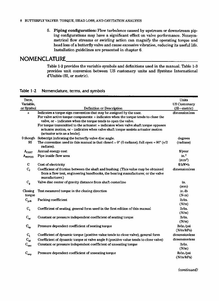
Table 1-1 Table 1-2 Table 1-3
Table 2-1
Table 6-1 Table 6-2 Table 6-3 Table 6-4
Torquecomponentcategory .................................... 2 Nomenclature. terms. and symbols .............................. 8 Conversion of units .......................................... 13
Calculation data for constant head source example . . . . . . . . . . . . . . . . 51
Typical bearing friction coefficients ............................. 82 Typical packing coefficients ................................... 82 Typical seating coefficients ................................... 82 Typical full open flow coefficients, C, and K, ..................... 83
vii

Preface
The purpose of this manual is to present a recommended method for calculating oper- ating torque, head loss, and cavitation for butterfly valves typically used in water works service. It is a discussion of recommended practice, not an American Water Works Association (AWWA) standard. The text provides guidance on generally avail- able methods for using butterfly valves as well as their cavitation, flow, and torque characteristics. Questions about specific situations or applicability of specific valves and values should be directed to the manufacturers or suppliers. Information in this manual is useful for technicians and engineers who want a basic understanding of the calculations associated with the use and specification of butterfly valves. The valve torque, flow, and cavitation coefficients given are typical but generic values covering a variety of products. Actual flow, cavitation, or torque coefficients for a particular man- ufacturer’s valve should be used in calculations for a specific valve and application to obtain the highest calculation accuracy.
The history of this manual is related to that of American National Standards Institute ANSIIAWWA C504, Standard for Rubber-Seated Butterfly Valves. Until the 1994 edition, ANSIIAWWA C504 included Appendix A, which described a recom- mended method of calculating torques for butterfly valves. This appendix was deleted from the 1994 and subsequent editions of the standard for several reasons. The AWWA Standards Council directed that standards documents should not contain appendixes; appendix text should either be moved to the main body of the standard or be made into a separate, stand-alone document. Members of the committee for ANSIIAWWA C504 at the time were concerned that the existing text of Appendix A no longer represented the current state of knowledge concerning methods for calculating torques for butterfly valves. In 1993, a subcommittee was established to rewrite Appendix A as a separate manual incorporating the state-of-the-art theory for calculating torque and head-loss values for butterfly valves. This second edition of the manual expanded the intro- duction and some equations, added torque sign conventions, added double offset disc design variables and calculations, added equations for eccentricity torque, added met- ric units and equivalents, consolidated the nomenclature, and corrected some errors.
Manual M49 refers to AWWA standards available for purchase from the AWWA Bookstore. Manufacturers graciously provided valve illustrations and other documen- tation. AWWA does not endorse any manufacturer’s products, and the names of the manufacturers have been removed from the material provided.
ix


Chapter 5 Valve Testing ......................................................................... 67 Testing Requirements, 67 Flow Test Procedure, 69 Seating/Unseating Torque Test Procedure, 73 References, 75
Chapter 6 Valve Applications ............ ...................................................... 77 Actuator Sizing, 77 Extended Bonnet Installation, 78 Effects of Pipe Installations, 80 Typical Range of Coefficients, 81 Cautions, 84 Summary, 85 References, 86
Index, 87
iv

Chapter 1
Introduction
Torque, head loss, and cavitation are important considerations in the selection and sizing of butterfly valves in water systems. Butterfly valve components must be able to withstand the forces and torques generated during use, and the actuator must operate and seat the valve. The head loss developed across any valve adds to the energy costs of a pumping system. Cavitation can damage a valve or adjacent piping if not controlled.
The topics in this introductory chapter include an explanation of basic butterfly valve design elements and their role in predicting torque, head loss, and cavitation.
Valve torque is calculated to allow proper actuator sizing and to provide assur- ance that the valve components can withstand the internal forces produced by flowing water and fluid pressure. Head loss characteristics must be known to predict torque, and system designers also use these data to calculate pump head requirements and to evaluate the energy costs associated with the head loss across the valve in pumping applications. Cavitation is analyzed to prevent undesirable sound and vibration and to prevent damage to the valve and adjacent piping.
Torque, head loss, and cavitation vary with a valve’s angle of opening. These characteristics also depend on the geometry of the valve body and disc and on the characteristics of the system in which the valve is installed. Flow testing of a valve assumes a smooth, undisturbed flow upstream and downstream of the valve such as that produced by a long run of straight, constant-diameter pipe. Variation from this ideal condition can have an effect on valve torque and head loss. Flow disturbances caused by piping configuration-such as elbows, reducers, or other valves within a dis- tance equal to eight times the diameter upstream of the valve-require further review by applying the recommendations given in chapter 6.
Coefficients provided by the butterfly valve manufacturer may be used to calcu- late the torque and head loss as described in this manual, provided that the values are determined based on testing methods described in chapter 5. The coefficients provided in this manual are presented only for illustrative purposes. Information from the valve manufacturer is needed before calculations can be performed for a specific use. How- ever, generalized information may assist in determining the applicability or sensitivity of some characteristics.
Cavitation data can also be determined by flow testing. Values for a range of valve angles are helpful in predicting whether cavitation will occur in a given application.
1

2 BUTTERFLY VALVES: TORQUE, HEAD LOSS, AND CAVITATION ANALYSIS
SCOPE This manual covers round or circular butterfly valves within the scopes of American Water Works Association (AWWA) and American National Standards Institute (ANSI) standards ANSI/AWWA C504-10 (2010) and ANSUAWWA C516-10 (2010) with essen- tially full-ported designs where the port diameter and disc diameter are close to the nominal pipe size (NPS) or nominal diameter (in inches [in.] or millimeters [mml). This includes sizes 3 in. (75 mm) and larger.
DISCUSSION OF TORQUE CALCULATIONS The torque calculations are broken into 10 separate torque components and each is derived from a first-principles approach. The 10 separate torque components are clas- sified into 2 categories: (1) passive or friction based or (2) active or dynamically gener- ated. These 10 components are listed in Table 1-1.
Each of these components is evaluated mathematically from a first-principles approach and their equations are presented, except for the buoyancy torque (item 7) and the thrust bearing torque (item 5). These two are generally considered as neg- ligible for this scope of the valves. The components of hub seal friction torque (item 31, weight and center of gravity torque (item 6), lateral offset or eccentricity torque (item 8), and hydrostatic unbalance torque (item 10) may not be applicable depend- ing on the valve design and installation variables. Seating (and/or unseating) fric- tion torque (item l), packing friction torque (item 2), bearing friction torque (item 41, and dynamic or fluid dynamic torque (item 9) should always be included in operating torque calculations.
The passive torque components are friction related and in general either are con- stant for a given valve or are directly dependent on the differential pressure. These components always oppose actuator motion and are generally considered to be essen- tially the same magnitude in either direction of operation (opening or closing), except for seating and unseating. Seating and unseating torque may be evaluated separately or considered the same when differences are small.
The active or dynamic torque components are generated in the valve by the effects of the internal fluid media (water) or gravity acting on the valve. These components may oppose or assist the actuator’s operation. Since dynamic torque generally tends to close the valve, the actuator may act as a brake to control the speed of the closing stroke but must also overcome this torque in the opening stroke.
Table 1 - 1 Torque component category
Item Number Torque Component Torque Category 1 2 Packing friction torque 3 Hub seal friction torque 4 Bearing friction torque 5 Thrust bearing friction toraue
Seating (and/or unseating) friction torque Passive or friction based components
6 7 Buoyancy torque 8 9 10 Hydrostatic unbalance torque
Weight and center of gravity torque
Lateral offset or eccentricity torque Dynamic or fluid dynamic torque
Active or dynamically generated components

INTRODUCTION 3
The separate effects methodology provided here is generally used for valves of larger sizes. Actuator sizing in valves 12 in. (300 mm) and smaller is driven primar- ily by the passive friction based torque requirements, as the active torque components are a small fraction of the total required operating torque. The transition point where the dynamic torque components become the major part of the total required torque depends on many factors of the valve design. However, it can be generally stated that this transition occurs in the 14411. (350-mm) to 30411. (900-mm) range for this scope. Actuator sizing for valves larger than 30 in. (900 mm) is almost always significantly based on the dynamic flow conditions.
Based on this and the fact that the smaller-sized valves are easily tested and grouped into a smaller range of required actuator torque over the full span of the design pressure and flow rate, this complex calculation methodology may be replaced by a simple calculation based on size and pressure using curve-fitting techniques of test data. In the smaller sizes, the manufacturer may provide curve-fit equations, graphical, or tabulated information.
This separate effects methodology becomes increasingly important in the larger valve sizes-say over 4 8 in. (450 mm) and larger-and at very high fluid line veloci- ties greater than 16 ft/sec (4.9 m/sec). It is economically or physically infeasible to test many large-diameter valves; and using separate effects calculations, model test data, and grouping of the test data is necessary. The modeling techniques of dimensionless coefficients, hydraulic similitude, grouping, interpolation, and extrapolation are not discussed in this manual.
Since the dynamic torque component is a function of the valve diameter to the third power (D3), it becomes the major torque affecting the actuator sizing of the larger-size valves. This is why the maximum operating flow rate or fluid line velocity is needed for actuator sizing of larger-size valves.
The hydrostatic unbalance torque is also of great importance (if it exists) to larger-valve sizes as it is a function of the diameter to the fourth power (D4), although it can be ignored as insignificant in valves =36 in. (900 mm) and smaller. It is seldom seen under actual operating conditions, but its influence can be very significant in valve sizes larger than 36 in. (900 mm).
This methodology is best applicable for determining the required actuator torque for the larger sizes of valves where the torque components are determined individually (rather than by curve-fitting techniques of the total torque) as the combination of both the operating shutoff differential pressure and maximum operating flow rate (or line velocity) has a significant effect on results.
The methods of calculating the required actuator torque, system flow, pressure drop, and cavitation indices described herein are also applicable to other quarter-turn valves such as ball, cone, and plug valves. The test-developed coefficients must be specific for the valve type and design, but the first-principles methodology is basically unchanged.
The flow and torque coefficient data used must be from the same valve design and same test procedure. Care should be taken not to use the flow coefficients from one valve design and apply them to another design.
UNCERTAINTY AND DIAMETER ASSUMPTIONS Uncertainty is a complicated subject and not a topic of this manual. Although there is an experimental accuracy associated with any data collection and reduction tech- nique, most laboratories and researchers use measurements of good accuracy and rep- licated data to minimize the uncertainty in the results. The use of this methodology provides a best estimate of normal operating torque requirements under the conditions
4 BUTTERFLY VALVES: TORQUE, HEAD LOSS, AND CAVITATION ANALYSIS
specified. The actuator sizing additional torque margin, allowances for in-service deg- radation, and/or safety factors for power (electric motor, cylinder, or vane) actuators are discussed in other ANWAWWA standards.
For the valve shaft diameter, valves meeting ANSI/AWWA C504-10 (2010) have the minimum shaft diameters given in the standard. ANSI/AWWA C516-10 (2010) does not provide minimum shaft diameters. It is always best to obtain the shaft diam- eter by measurement or from the manufacturer.
Many sources are available for butterfly valve flow and torque coefficients. These include valve engineering handbooks, published research papers, and valve supplier manuals or bulletins. The manufacturer generally publishes flow coefficients (i.e., C, or K) for most valves. Some manufacturers consider the torque coefficients (C,) to be proprietary information and may not publish these data.
Much existing data were developed before published standardization methods, and investigators may have based their calculations on different valve diameter mea- surements. The mqjor valve diameters include nominal pipe size (NPS), approach pipe inside diameter, valve port diameter, and valve disc diameter (see Figure 2-1 in chap- ter 2). Also, various publications use slight variations of these first-principles equa- tions or use different units of measure. The user is cautioned to evaluate and convert such data to the proper format and units of measure. For instance, some butterfly valve manufacturers provide a dynamic torque coefficient for use in the formula, Td = C, AP. When equated to the formula used herein, Td = C, D3 AP and C, = C, D3 or C, = C,/D3.
If the data were developed based on disc diameter and the prediction calcula- tions employed the nominal diameter, there will be a larger uncertainty in the results than if the disc diameter were used. This manual of practice gives direction on what diameter should be used for standardization, consistency, and uncertainty purposes. However, for many good engineering reasons, much of the available data does not con- form to these guidelines. In many instances the exact approach pipe inside diameter, valve port diameter, and/or valve disc diameter are not known at the time the calcu- lation is performed.
For the valves within the scope of this manual, the approach pipe inside dia- meter, valve port diameter, and valve disc diameter are almost always less than the valve’s nominal diameter. Therefore, the use of the nominal diameter (nominal pipe size) as the diameter in torque prediction calculations will often provide a conserva- tively high torque value (as the diameter appears in the numerator of the equations). The nominal diameter of the valve may be used in these prediction calculations in lieu of the approach pipe inside diameter, valve port diameter, or valve disc diameter as specified with the understanding that the torque results have a higher uncertainty and are generally greater than a more precise evaluation. In all cases, if the diameter basis on which the data are based is known, the use of the same variable provides the highest accuracy prediction.
The flow coefficient, C, and K, testing and data collection methods follow that prescribed in the Instrument Society of America (ISA) standard ANSI/ISA S75.02.01- 2008 (ISA 2008) and are based on the test pipe inside diameter.
DISCUSSION OF HEAD LOSS, CHOKING, AND CAVITATION Most analyses can be performed without regard to choking limitations. Choking con- siderations add additional calculations and difficulty to the methodology but do not critically affect the results of most head loss, flow, or torque calculations within the scope of this manual. For more information on choking calculations also see ANSI/ ISA S75.01.01-2007 (ISA 2007), ANSI/ISA S75.02.01-2008 (ISA 2008), and Hutchin- son (1976).

INTRODUCTION 5
BUlTERFL
The calculations of flow rate (or fluid velocity), valve head loss (or pressure drop), dynamic torque, and bearing friction torque given here do not include the effect of valve choking. Other coefficients (FL, FL2, or K,) are required to evaluate choking. It is not normally intended that the systems where the valves of this scope are used should become fully choked at the maximum flow rates. If choking occurs, additional calculations are required to determine when classic head loss, flow, and torque equa- tions are no longer appropriate and choked flow equations should be used. To add choking to the calculations requires the liquid pressure recovery factors of the valve without attached fittings (FL?), and the system resistance must be determined for the part of the system upstream of the valve as well as the total system equivalent resis- tance. Analyses including choked flow evaluations are not normally performed for the following reasons:
These calculations add significant complexity to the methodology.
In-depth operating system knowledge is not readily available to effectively perform the calculations.
Torque calculations based on classic head loss and flow are generally conservative.
When choked, the flow rate reaches a maximum limit (corresponding to the line pressure, choked flow) and the dynamic torque also does not continue to increase in proportion to increased head or pressure differential (because the flow rate is not increasing). Bearing friction torque does continue to increase with increasing differen- tial pressure, and the method of calculating the differential pressure across the valve changes to the maximum shutoff differential minus the system loss at the choked flow rate. The cavitation analysis in this manual can also be used to determine if choking is a concern, as choking is actually caused by the development of heavy cavitation usu- ally resulting in vapor pressure downstream of the valve.
Figure 1-1 shows typical results of how cavitation and choking occur in a but- terfly valve. From a calculation standpoint, the flow and valve are treated as classi- cal flow up to the F, point and as constant flow rate at all higher valve differential pressures. There is a small calculation error in the transition zone where actual test results are not linear in Figure 1-1. For critical, highly throttled pressure or flow con- trol applications, it may be necessary to perform flow calculations that consider cavita- tion and choked flow to assure good design practices.
-Y VALVE DESIGN The butterfly valve is a versatile component for use as both a shutoff and throttling valve in water systems. Butterfly valves are commonly supplied for the water industry in accordance with ANSIIAWWA C504-10 (20101, Standard for Rubber-Seated But- terfly Valves, or ANSIIAWWA C516-10 (20101, Standard for Large-Diameter Rubber- Seated Butterfly Valves Sizes 78 in. (2,000 mm) and Larger. As shown in Figure 1-2, this type of valve consists of a circular disc supported in the body with a shaft or two stub shafts. The quarter-turn operation is accomplished with a top-mounted hand lever, gear actuator, or power actuator. The rubber seat, an innovation of the 1930s, allows the valve to operate easily and provide drop-tight seating.
The flow passes on both sides of the disc when the valve is open. Some discs have flow-through areas that allow flow to pass through portions of the disc cross sec- tion when open. Flow is controlled by positioning the disc from 0" (closed position) to the full open (approximately 90") position. The approximate effective throttling range for a butterfly valve is 15" to 75" open, but the range can vary based on application. Throttling at lower angles may cause erosion due to excessive velocities or cavitation.

6 BUTTERFLY VALVES: TORQUE, HEAD LOSS, AND CAVITATION ANALYSIS
- Fully -
- - - Choked Flow
-
Flashing --c Cavitation ncreasing Region Pd 5 pv
LI
E - Zone
0 , Free
G - 3
3-
Q a - -avitation Y
Region 6 - 3 - U
tan Y = C v
a U al Y 0
Data for a Constant Valve Angle and
Upstream Pressure I I I ( I I ’ I ’ 1
5
Square Root of Valve Pressure Drop
Figure 1-1 explanation (definitions of variables appear in Table 1-2)
Typical butterfly valve flow, differential pressure, cavitation, and choking graphical
Actuator Actuator
Body Body
Disc Disc
Symmetrical (On-Center) Design Single-Offset Design Wafer End Configuration Flanged End Configuration
Sources: Courtesy of Henry Pratt Co. (left) and courtesy of DeZURIK (right).
Figure 1-2 Typical butterfly valve construction

INTRODUCTION 7
See chapter 4 for a discussion of cavitation. Throttling at higher angles may pro- vide limited control, because the valve has little effect on the system flow in most applications.
SYSTEM CONDITIONS Analysis requires an understanding of system conditions that affect the torque, head loss, and cavitation calculations for butterfly valves, including those conditions in the following list:
1. Fluid flow velocity or flow rate: The maximum anticipated flow rate or fluid flow velocity through the nominal valve size should be determined with consider- ation of hydraulic design conditions and may include line break or other faulted condition flows when appropriate. The maximum anticipated flow velocity (or flow rate) is needed for the fluid dynamic torque calculations.
2. Differential pressure: The maximum differential pressure is needed for the torque calculations. Cavitation calculations also require determination of pressure just upstream and downstream of the valve at the most severe throttling condition.
3. Piping installation: Free discharge outlet and reservoir inlet installations (illus- trated in Figure 1-3) represent unique applications that exceed the scope of this manual. These installations can affect both the torque and head loss character- istics of a butterfly valve. The valve manufacturer should be made aware of these conditions when applicable.
4. Operating temperature: Rubber-seated butterfly valves and actuators are designed to seat, unseat, control, and rigidly hold the valve discs under a wide range of operating conditions. Temperature can affect seating torques and friction factors for valve bearings, so it should be considered. The operating temperature of the valves within this scope is 33" F to 125" F (0.6" C to 51.7" C) . The valve manu- facturer should be advised when operating temperatures are near the extremes or exceed the extremes of this range.
Free
Discharge
/ Outlet
~ ~~ ~~~ ~ ~
Figure 1-3 Free discharge and reservoir inlet installations of butterfly valves
8 BUTTERFLY VALVES: TORQUE, HEAD LOSS, AND CAVITATION ANALYSIS
5. Piping configuration: Flow turbulence caused by upstream or downstream pip- ing configurations may have a significant effect on valve performance. Nonsym- metrical flow streams or swirling action can magnify the operating torque and head loss of a butterfly valve and cause excessive vibration, reducing its useful life. Installation guidelines are presented in chapter 6.
NOMENCLAlZIRE Table 1-2 provides the variable symbols and definitions used in the manual. Table 1-3 provides unit conversion between US customary units and Systbme International d'Unit6s (SI, or metric).
Table 1-2 Nomenclature, terms, and symbols
Term, Variable,
Units US Customary
or Symbol Definition or Description (SI-metric) Indicates a torque sign convention that may be assigned by the user. dimensionless f
0 though 90
ACOST
APIPEID
Cf
c,
C
Closing torque
'wk
CS
csc
CS*
ct cttl
cus,
cusp
- - For valve active torque components: + indicates when the-torque tends to close the
valve, or - indicates when the torque tends to open the valve. For torque transmitted to the actuator: + indicates when valve shaft torque opposes
actuator motion, or - indicates when valve shaft torque assists actuator motion (actuator acts as a brake).
Subscript indicating the butterfly valve disc angle. The convention used in this manual is that closed = 0" (0 radians); full open = 90" (n/2
Annual energy cost Pipe inside flow area
radians).
Cost of electricity Coefficient of friction between the shaft and bushing. (This value may be obtained
from a flow test, engineering handbooks, the bearing manufacturer, or the valve manufacturer.)
Valve disc center of gravity distance from shaft centerline
Test measured torque in the closing direction
Packing coefficient
Coefficient of seating, general form used in the first edition of this manual
Constant or pressure independent coefficient of seating torque
Pressure dependent coefficient of seating torque
Coefficient of dynamic torque (positive value tends to close valve), general form Coefficient of dynamic torque at valve angle 0 (positive value tends to close valve) Constant or pressure independent coefficient of unseating torque
Pressure dependent coefficient of unseating torque
degrees (radians)
$/year in.2
(mm2> $lkW*h
dimensionless
in. (mm) in.-lb (N-m) lblin. (NJm) lb/in. (NJm) lblin. ( N W
1blin.lpsi (Nlm/kPa)
dimensionless dimensionless
lblin. (NJm)
1blin.lpsi (N/m/kPa)
(continued)

INTRODUCTION 9
Table 1-2 Nomenclature, terms, and symbols (continued)
Term, Variable,
Units US Customary
or Symbol Definition or Description (SI-metric) Valve flow coefficient. The flow of water through a valve at 60" F in US gpm at a pres- gpmlpsi"
~~
sure drop of 1 psi (lb/in.2). Metric Units Note: In metric units, this variable is often identified as K, However,
this is not used in this manual as it is easily confused with the resistance coef- ficient, K. When the resistance coefficient, K, is the resistance coefficient of the valve, it is subscripted with a "V" to indicate this reference, K,
ranging 5-30" C through a valve in cubic meters per hour (1n3/h) with a pressure drop of 1 bar (1 bar = 100 kPa). For purposes of this manual, the metric unit version of C, will be identified by the variable symbol Cvm.
The metric flow coefficient, & is defined as: the flow of water with temperature
The metric equivalent to C, (referred to as & in other texts)
Nominal valve diameter
Reducer reduced pipeline diameter
Reducer large pipeline diameter
Disc diameter
Pipe inside diameter
Reference valve size
Shaft diameter
Size of model or test valve
Efficiency of pump and motor set (80% 0.80, typical)
Liquid pressure recovery factor of a valve without attached fittings. This experimentally determined factor depends on the internal valve geometry.
Resultant force vector for hydrostatic torque
Gravitational constant Acceleration due to gravity, 32.2 ft/sec2 (9.81 m/sec2) Additional seismic acceleration loading multiplier. For applications involving addi-
tional seismic loading, component weight may be multiplied by G (horizontal) or G*l (vertical), where G is the additional seismic acceleration.
Packing height
Flow resistance coefficient of any component or fitting Reducer resistance coefficient based on the reduced diameter, D, Reducer resistance coefficient based on the large diameter, D, System flow resistance coefficient (excluding the valve) Flow resistance coefficient of the valve Flow resistance coefficient of valve at full open (=go", =n/2 radians). Note: Use of K,,
assumes the valve travels 90" to full open.
~~ ~
(No metric)
No US customary
(m3/hr/Bars) (m3/hr/( 100
in. (mm)
in. (mm)
in. (mm)
in. (mm)
in. (mm)
in. (mm)
in. (mm)
in. (mm)
%
dimensionless
kPa) ")
lb (N)
ft/sec2 (m/sec2)
dimensionless
in. (mm)
dimensionless dimensionless dimensionless dimensionless dimensionless dimensionless
(continued)

10 BUTTERFLY VALVES: TORQUE, HEAD LOSS, AND CAVITATION ANALYSIS
Table 1-2 Nomenclature, terms, and symbols (continued)
Term, Variable,
Units US Customary
or Symbol Definition or Description (SI-metric) Valve resistance coefficient based on the reference diameter, D,, (typically the nomi- dimensionless KVd,
KVd2
Kve L
Opening torque PC
'd
'EW
PSE PU
put
P"
pvt
Q
S C
s, SSE SYS
'boo
Tbt
Tbtotale
Tbw
TbO
TCge
Tcgoo
nal diameter, D) Valve resistance coefficient based on the diameter, D, Flow resistance coefficient of the valve at valve angle 8 Reducer end-to-end length
Test measured torque in the opening direction
Pressure class or maximum design pressure (the greater of)
Reference downstream pressure for cavitation analysis
Pressure equivalent to disc and shaft weight
Pressure scale effects factor for cavitation analysis Reference upstream pressure for cavitation analysis
Upstream pressure from laboratory test for cavitation analysis
Vapor pressure adjusted for temperature and atmospheric pressure. (Example: P, =
Vapor pressure from laboratory test -14.4 psig [-99.6 kPa] for water at 60" F [IS" C], measured at sea level.)
Volumetric flow rate
Sign convention variable: For torque active components: +1 when the torque tends to close the valve, or -1 when
For center of gravity torque: the sign convention variable is +1 when the center of the torque tends to open the valve.
gravity is above the horizontal when the disc is in the full open position, or -1 when the center of gravity is below the horizontal when disc is full open.
opposes actuator motion, or negative value when valve shaft torque assists actua- tor motion (actuator is acting as a brake).
For torque transmitted to the actuator: a positive value when valve shaft torque
Specific gravity of liquid relative to water at 60" F (16" C) (water = 1.0)
Sizing scale effects factor for cavitation analysis Subscript indicating system piping and components less the butterfly valve Bearing torque at valve angle 0" (always positive)
Measured bearing torque from testing
Total bearing torque at valve angle 8 with addition of disc weight relative to installa-
Bearing torque from disc weight relative to installation orientation (always positive) tion orientation (always positive)
Bearing torque at valve angle 8 (always positive)
Center of gravity torque at valve angle 8. (Positive value tends to close the valve; neg-
Center of gravity torque at valve angle 0". (Positive value tends to close the valve; ative value tends to open the valve.)
negative value tends to open the valve.)
dimensionless dimensionless
in. (mm) in.-lb (N-m)
dimensionless (or Psig)
psi ( k W psi
( k W dimensionless
psi (kPa) psi
(kPa) psi
(kPa) psi
( k W gpm
(m3hr) dimensionless
dimensionless
dimensionless
in.-lb (or ft-lb) (N-m) in.-lb (N-m)
in.-lb (or ft-lb) (N-m)
in.-lb (or ft-lb) (N-m)
in.-lb (or ft-lb) (N-m)
in.-lb (or ft-lb) (N-m)
in.-lb (or ft-lb) (N-m)
(continued)

INTRODUCTION 11
Table 1-2 Nomenclature, terms, and symbols (continued)
Term, Units Variable, US Customary
or Symbol Definition or Description (SI-metric) Dynamic torque at valve angle 8. (Positive value tends to close the valve; negative
Measured dynamic torque from testing. (A positive value indicates a tendency to
Eccentricity torque. (Positive value tends to close the valve; negative value tends to
Note: Only considered at the seated position during opening or at closing. Hydrostatic torque. (Positive value tends to close the valve; negative value tends to
Note: Only considered at the seated position during opening or at closing. Packing and hub torque (always positive)
value tends to open valve.)
close the valve.)
open valve.)
open the valve.)
Measured packing and hub torque from testing
Seating torque (always positive)
Measured seating torque from testing (always positive)
Total operating torque at valve angle 8 (positive value opposes actuator motion; nega-
Total closing torque a valve angle 8. (Positive value opposes actuator motion; nega-
Total opening torque a valve angle 8. (Positive value opposes actuator motion; nega-
Total seating torque. (Positive value opposes actuator motion; negative value assists
Total unseating torque. (Positive value opposes actuator motion; negative value
Unseating torque (always positive)
tive value assists actuator motion), general form
tive value assists actuator motion.)
tive value assists actuator motion.)
actuator motion.)
assists actuator motion.)
Measured unseating torque from testing (always positive)
Pump usage percent, 100% (1.0) equals 24 hours per day Units Conversion Factor: US customary for torque in in.-lb Ucl = 1 in./in. US customary for torque in ft-lb: U,, = 1/12 (0.0833) in./ft Metric for torque in N-m: U,, = 1 x Units Conversion Factor: US customary for torque in in.-lb: U,, = 1 in./in. US customary for torque in ft-lb Uc, = 1/12 (0.0833) in./ft Metric for torque in N-m: U,, = 1 x 10⁻⁶ (0.000001) m2/mm2 Velocity of fluid flow
(0.001) m/mm
Subscript indicating the butterfly valve Maximum full open velocity. (Note: Based on nominal valve diameter if converted
Approach fluid velocity of the valve from a quantity flow rate.)
Approach velocity of fluid flow at valve angle 0
in.-lb (or ft-lb) (N-m) in.-lb (N-m)
in.-lb (or ft-lb) (N-m)
in.-lb (or ft-lb) (N-m)
in.-lb (or ft-lb) (N-m) in.-lb (N-m)
in.-lb (or ft-lb) (N-m) in.-lb (N-m)
in.-lb (or ft-lb) (N-m)
in.-lb (or ft-lb) (N-m)
in.-lb (or ft-lb) (N-m)
in.-lb (or ft-lb) (N-m)
in.-lb (or ft-lb) (N-m)
in.-lb (or ft-lb) (N-m) in.-lb (N-m)
% in.1in. (in.1ft)
(mlmm)
in./in. (in./ft) (mVmm2)
ft/sec (mlsec)
ft/sec (m/sec) ftlsec
(m/sec) ft/sec
(m/sec)
(continued)

12 BUTTERFLY VALVES: TORQUE, HEAD LOSS, AND CAVITATION ANALYSIS
Table 1-2 Nomenclature, terms, and symbols (continued)
Term, Variable,
Units US Customary
or Symbol Definition or Description (SI-metric) W,, Weight of valve disc lb
Weight of the disc and shaft(s) assembly (banjo). For applications involving additional seismic loading, W,,, may be multiplied by G or (GA), where G is the additional gravitational acceleration multiplier.
Weight of shaft(s)
Size scale exponent for cavitation analysis Reducer (increaser) included angle, degrees; for angles 5 45" (n/4 radians)s
Pipe angle from vertical axis for center of gravity relative to seat location, 0" to 90" (or 0 to n/2 radians) when seated position is above horizontal; >90" to 180" (or n/2 to n radians) when seated position is below horizontal.
For reducer flow resistance calculation: reducer (increaser) diameter ratio Center of gravity offset angle (nonsymmetric disc designs). (May also include an
adjustment for valve designs where the seating angle is not perpendicular to the pipe axis.)
Head loss between any two reference points in a system
Head loss across the closed valve or total system with valve closed
Measured head loss across the pipe during testing without the valve
Head loss across the system
Measured head loss across the valve and pipe during testing
Head loss across the valve, general
Head loss across the valve at angle 0
Pressure drop (or loss) between any two reference points in a system
Maximum pressure drop (or loss) across the closed valve or total system with valve
Measured pressure drop across the disc from testing closed
Pressure drop (or loss) across the valve, general form
Pressure drop (or loss) across the valve at valve angle 0
Pressure drop (or loss) while at disc angle 0
Disc axial offset. (Note: E, equals 0 for symmetric disc designs.). See Figure 2-3.
Disc lateral offset. Note: E~ equals 0 for symmetric or single-offset disc designs. Sign Convention Note: For hydrostatic torque, E~ is positive when oriented above
the valve centerline, and negative when oriented below the valve centerline. See Figure 2-3.
Valve opening position angle, closed = 0" (0 radians); full open = 90" (d2 radians)
lb (kg)
dimensionless degrees (radians) degrees (radians)
dimensionless degrees (radians)
feet of water (meters of water)
feet of water (meters of water)
feet of water (meters of water)
feet of water (meters of water)
feet of water (meters of water)
feet of water (meters of water)
feet of water (meters of water)
psid (kPa) psid (kPa) psid (kPa) psid (kPa) psid (kPa) psid (kP4
in. (mm)
in. (mm)
degrees (radians)
(continued)
INTRODUCTION 13
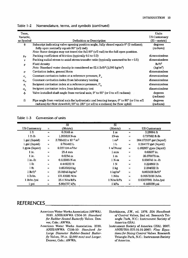
Table 1-2 Nomenclature, terms, and symbols (continued)
Term, Variable,
Units US Customary
8
P P
P
V
U
UC
act
ui
uit
4
n
or Symbol Definition or Description (SI-metric) Subscript indicating valve opening position angle, fully closed equals 0" (0 radians); degrees
(radians) fully open normally equals 90" (n/2 rad). Note: Some designs may not travel the full 90" (n/2 rad) to the full open position. Packing coefficient of friction (typically 0.1 to 0.3) Packing radial stress to axial stress transfer ratio (typically assumed to be = 0.5) Fluid density Note: Standard water density is considered as 62.4 lb/ft3 (1,000 kg/m3) Cavitation index, general form Constant cavitation index at a reference pressure, P, Constant cavitation index from laboratory testing Incipient cavitation index at a reference pressure, P, Incipient cavitation index from laboratory test Valve installed shaft angle from vertical axis, 0" to 90" (or 0 to n/2 radians)
dimensionless dimensionless
lb/ft3
dimensionless dimensionless dimensionless dimensionless dimensionless
degrees (radians)
(kg/m3)
Pipe angle from vertical axis for hydrostatic and bearing torque, 0" to 90" (or 0 to n/2 degrees (radians) radians) for flow downhill; 90" to 180" (or n/2 to n radians) for flow uphill
Table 1-3 Conversion of units
SI SI US Customary - - (Metric) (Metric) = US Customary
1 ft - - 0.3048 m l m - - 3.28084 ft 1 ft-lb
1 gal (liquid) 1 gal (liquid)
1 gpm (liquid) 1 in. 1 in.
1 in.-lb 1 lb 1 lb
1 lb/ft3 1 lb/in.
1 lb/in./psi
- - 1.355818 N-m = 3.785412 x m3 - - 3.785412 L - - 0.227124 m3/hr
25.4 mm 0.0254 m
- - - -
- - 0.112985 N-m - - 4.448222 N - - 0.4535924 kg = 16.01846 kg/m3 - - 175.12685 N/m - - 25.4 N/m/kPa
1N-m 1 m3 1 L
1 m3/hour 1 mm l m
1 N-m 1 N 1 kg
1 kg/m3 1 N/m
1 N/m/kPa
0.737562 ft-lb 264.172037 gal (liquid) 0.264172 gal (liquid)
4.402867 gpm (liquid) 0.03937 in.
39.370078 in. 8.850745 in.-lb
0.224809 lb 2.204622 lb
0.062428 lb/ft3 0.00571015 lb/in.
0.03937001 lb/in./psi 1 psi - 6.894757 kPa 1 kPa - - 0.145038 psi -
REFERENCES American Water Works Association (AWWA).
2010. ANSIIAWWA C504-10: Standard for Rubber-Seated Butterfly Valves. Den- ver, Colo.: AWWA.
American Water Works Association. 2010. ANSI/AWWA C516-10: Standard for Large Diameter Rubber-Seated Butter- fly Valves, 78 in. (2,000 mm) and Larger. Denver, Colo.: AWWA.
Hutchinson, J.W., ed. 1976. ISA Handbook of Control Valves, 2nd ed. Research Tri- angle Park, N.C.: Instrument Society of America (ISA).
Instrument Society of America (ISA). 2007. ANSI/ISA-S75.01.01-2007: Flow Equa- tions for Sizing Control Valves. Research Triangle Park, N.C.: Instrument Society of America.

14 BUTTERFLY VALVES: TORQUE, HEAD LOSS, AND CAVITATION ANALYSIS
Instrument Society of America. 2008. ANSI/ ISA-S75.02.01-2008: Control Valve Ca- pacity Test Pmeduure. Research Trian- gle Park, N.C.: Instrument Society of America.

Chapter 2
AWWA MANUAL
Valve Torque
In a butterfly valve, torque is the turning force needed to rotate the valve disc or hold it in position. Torque varies with system conditions, valve design, and disc position. The methodology given in this manual is a step-by-step procedure for predicting valve operating torque and represents the current method used by many butterfly valve manufacturers for the water industry.
DEFINITIONS The methodology that follows is based on several terms and concepts that are defined in this section.
Flow Coefficients, Cv and K or I(, For liquids, the flow coefficient, C,, expresses the flow capacity in gallons per minute of 60" F (15" C) water with a pressure drop of 1 psi (6.89 kPa). For liquids, the flow resistance (or velocity head loss) coefficient, K, expresses the head loss as directly proportional to the velocity head. The subscript "v" is added to K to indicate when the coefficient is relative to the valve. The metric equivalent to C, is often referred to as K,,. In this manual, K., will always refer to the flow resistance coefficient of the valve and not the metric equivalent to C,.
Flow coefficients are typically developed using a straight-run test pipe of the same nominal diameter as the valve. The valve may be connected to a pipeline with a slightly different inside diameter (ID), as shown in Figure 2-1. For example, unlined standard-weight 24-in. (600-mm) pipe has an ID of 23.25 in. (590.60 mm). Regard- less of true or installed pipe ID, the valve calculations are generally based on nominal valve size, i.e., 24 in. (600 mm). Also, butterfly valve inlet diameters or port diameters are often less than the nominal diameters; however, torque coefficients are still based on disc diameter. Finally, the diameter of the disc is usually less than the pipe ID; disc diameter is generally used in calculating hydraulic forces on the disc and shaft bear- ings. (Note: There are several variations of flow coefficients such as K.,, C,, C , and C,. This manual primarily discusses the use of the resistance coefficient, Yr, and flow coefficient, C,, from the basic fluid equations [Crane 20091):
15

16 BUTTERFLY VALVES: TORQUE, HEAD LOSS, AND CAVITATION ANALYSIS
Pdrt Diameter
Diameter
Figure 2-1 Valve disc, port, and pipe diameters
K x V2 Kv x V: AH = ; or AHv = 2 x g 2 x g Eq 2-1
and,
Where: Units
US Customary Variable Definition or Description (SI-metric)
gpm/psi" (No metric)
C, Valve flow coefficient. The flow of water through a valve at 60" F
Metric Units Note: In metric units, this variable is often identified as yI. However,
in US gpm at a pressure drop of 1 psi (lb/in2)
this is not used in this manual as it is easily confused with the resistance coefficient, K. When the resistance coefficient, K, is the resistance coefficient of the valve, it is subscripted with a %" to indicate this reference, yI.
The metric flow coefficient, K,,, is defined as the flow of water with temperature ranging 6-30" C through a valve in cubic meters per hour (m3/h) with a pressure drop of 1 bar (1 bar = 100 kPa). For purposes of this manual, the metric unit version of C, will be identified by the variable symbol C,,,,.
(continued)

VALVE TORQUE 17
Units US Customary
Variable Definition or Description (SI-metric) C. The metric equivalent to Cv (referred to as K, in other texts) No US customary
Gravitational constant Acceleration due to gravity, 32.2 ft/sec2 (9.81m/sec2) Flow resistance coefficient of any component or fitting Flow resistance coefficient of the valve Volumetric flow rate
Specific gravity of liquid relative to water at 60" F (16" C) (water
Velocity of fluid flow = 1.0)
Approach fluid velocity of the valve
Head loss between any two reference points in a system
Head loss across the valve
Pressure drop (or loss) between any two reference points in a system
Fluid density Note: Standard water density is considered as 62.4 lb/ft3.
unit (m3/hr/(100 kPa)%)
ft/sec2 (m/sec2)
dimensionless dimensionless
gpm (m3/hr)
dimensionless
ft/sec (m/sec) ft/sec
(m/sec) feet of water
(meters of water) feet of water
(meters of water) psid (kP4 lb/ft3
(kg/m3)
Torque Coefficients, Ct and Cte Torque coefficients are developed on the installation of a valve in a straight run of pipe without upstream or downstream flow disturbances, such as nearby elbows, tees, or increasers. The effects of these pipe fittings are beyond the scope of this manual, and such conditions should be brought to the attention of the valve manufacturer. Specific installation guidelines are given in chapter 6. Manufacturers may consider torque coefficients to be proprietary information.
Bearing Torque, T,, and Tbe Bearing torque calculations are dependent on the valve disc and shaft diameters and the bearing coefficient of friction. Minimum shaft diameters are listed in ANSI/ AWWA C504-10 (2010). A methodology for sizing minimum shaft diameter is given in ANSUAWWA C516-10 (2010) for larger valves. Consult the valve manufacturer for actual diameters (or take measurements).
Bearing Coefficient of Friction, C, The shaft bearing material supports the shaft and disc in the valve body allowing rotation. The static coefficient of friction for the bearing and shaft material couple is needed to calculate valve torque. Consult the valve or bearing manufacturer or other mechanical engineering references and handbooks for typical friction coefficients.

18 BUTTERFLY VALVES: TORQUE, HEAD LOSS, AND CAVITATION ANALYSIS
Seating and Unseating Torque, Ts and Tus Seat designs are as numerous as valve manufacturers, and each has its own torque characteristics. This manual presents first-principles methodology for predicting seat- ing torque through use of seating coefficients that can be derived from tests for any type of seat. These coefficients may vary with seat material, temperature, and valve pressure rating. Normally seating torque and unseating torque are considered to be the same. However, some designs, such as double-offset designs, may have separate values or coef- ficients. The total unseating torque is sometimes referred to as the “break torque.”
Differential Pressure, AP The maximum differential pressure (APMAx) of a butterfly valve is defined as the max- imum difference between the upstream and downstream pressures when the valve is closed. During operation, the differential pressure varies based on system conditions and valve position. The upstream pressure can represent a constant head source, such as head from an elevated tank; a variable head source, such as head generated by a pump (see Figure 2-2); or a combination of both. For a conservative analysis, the downstream pressure may be assumed to be zero. The differential pressure is used to calculate the forces on the disc and to estimate the flow characteristics of the piping system and calculate the flow rate and valve pressure drop at various valve openings. To determine differential pressure with a variable head created by a pump, the pump curve can be used to calculate the flow through the valve at all valve positions.
Maximum System Flow Rate or Velocity, VMAX The maximum system flow rate with the valve fully open is used to calculate valve torques in the range of open positions. If the valve will be operated during temporary high-flow conditions such as fire flows or line-break flows, then the higher flow rate should be used. Although it is normally assumed that the maximum system flow rate is the same for both the opening and closing operations, it is often advantageous to consider extreme or emergency flow rates for only the operating (opening or closing) stroke of concern. This manual is based on the flow expressed as a fluid velocity in the pipe, not as a quantity such as gallons per minute (gpm), liters per minute (L/m), cubic feet per second (ft3/sec), or cubic meters per second (m3/sec). Conversions from quan- tity to pipe velocity are standard engineering practice and are not discussed in detail.
Equivalent Res~~a~.Syste.m ..Model +Variable 160 .~~~ ........................... ................ . .. .. .. I
Head Source
+Canstant Head Same
System Head LOSS
- c s t a t i c System Static Head Head
0 4 8 12 16 Fluid Wekxjty, fps
Figure 2-2 Constant and variable head source graph

VALVE TORQUE 19
Disc Geometry Disc geometry is important to a calculation of valve torque during valve travel (see Figure 2-3). A symmetrical disc normally has a tendency to close because of the flow rate passing across the disc. An offset disc normally has a tendency to close at most positions but may have a tendency to open at some positions. This manual ignores the third offset of the triple-offset design as being inconsequential to torque and flow cal- culations. The offset dimensions and e2 are defined in Table 1-2.
Shaft Orientation When a butterfly valve is installed in a horizontal pipe, the shaft orientation is impor- tant for calculating torque. When the valve shaft is horizontal in a horizontal pipe with one side empty, the water pressure above and below the shaft is unbalanced and tends to rotate the valve disc (see Figure 2-4). This orientation affects the calculations of hydrostatic torque and center of gravity torque. For the center of gravity torque, the position of the center of gravity when fully open, above or below the shaft axis, deter- mines if the center of gravity torque assists the opening or closing operation.
Flow Direction Through the Valve Because many butterfly valves have offset discs or other asymmetrical features, the orientation of the valve in the line with respect to flow is important. The valve may have a higher torque with flow toward the shaft side of the disc or with flow toward the other side. The manufacturer’s intended valve orientation must be assured dur- ing installation (see Figure 2-5). For purposes of this manual, the flow direction is referred to as seat-side flow when the seat is upstream of the valve shaft and as shaft- side flow when the seat is downstream of the valve shaft.
Sign Conventions Valve generated active torque components (Td, T,, Tcg, and T,,,) are considered as posi- tive values when they tend to close the valve and negative when they tend to open the valve. The signs for friction based (passive) torque components (Tb, T,, and TJ are always considered as positive values because they always oppose actuator motion. Therefore, the total required actuator torque in the opening direction is the summa- tion of all torque components, while the active torque components are subtracted in closing direction. The most conservative approach is to sum the absolute values of all torque components, but this may predict a substantially oversized actuator.
Symmetrical Single Offset
Double Offset
-1 81 (along pipe axis) 7 &I (along pipe axis)
Figure 2-3 Basic disc design geometry

20 BUTTERFLY VALVES: TORQUE, HEAD LOSS, AND CAVITATION ANALYSIS
I
Figure 2-4 Horizontal valve shaft in a horizontal pipe
TORQUE COMPONENTS Butterfly valve torque consists of several elements that contribute to the total valve operating torque depending on the position of the disc and the type of valve installa- tion. The general equations used in computing total operating torques are as follows:
Total Seating Torque:
T, = Tho, - Tcgo” -T, + T, + T - T,,, P
Total Unseating (Break) Torque:
T,, = Tboo + Tcgo” + T, + T, +Tp + T,,
Total Opening (Run) Torque:
TtoO = TbO + TcgO + TdO + Tp
Total Closing (Run) Torque:
= TbO - TcgO - TdO + Tp
Eq 2-3
Eq 2-4
Eq 2-5
Eq 2-6

VALVE TORQUE 21
Seat
Side
Flow
Shaft
Side
Flow
~~ ~~
$eat Centerline---- ------Shaft Centerlinf
82 (radial ohset) I
81 (along pipe axis) -It-- Shaft Centerline _I -Seat Centerline
81 (along pipe axis) -It--
Seat
Upstream
Shaft
Downstream
Shaft
Upst ream
Seat
Downstream
Figure 2-5 Seat-side and shaft-side flow orientations with single- and double-offset discs
Where: Units
US Customary
in.-lb (or foot-lb) (N-m)
in.-lb (or foot-lb) (N-m)
in.-lb (or ft-lb) (N-m)
Variable Definition or Description (SI-metric) T,,,
T,,
Tcge
Bearing torque* at valve angle 0" (always positive)
Bearing torque at valve angle 8 (always positive)
Center of gravity torque at valve angle 8. (Positive value tends to close the valve; negative value tends to open the valve.)
(continued)
22 BUTTERFLY VALVES: TORQUE, HEAD LOSS, AND CAVITATION ANALYSIS
Units US Customary
Variable Definition or Description (SI-metric) in.-lb (or ft-lb) Center of gravity torque at valve angle 09 (Positive value tends to
close the valve; negative value tends to open the valve.)
valve; negative value tends to open valve.)
tive value tends to open valve.)
closing.
tive value tends to open the valve.)
closing.
Dynamic torque at valve angle 8. (Positive value tends to close the
Eccentricity torque. (Positive value tends to close the valve; nega-
Note: Only considered at the seated position during opening or at
Hydrostatic torque. (Positive value tends to close the valve; nega-
Note: Only considered at the seated position during opening or at
Packing and hub torque (always positive)
Seating torque (always positive)
Total closing torque a valve angle 8. (Positive value opposes actua-
Total opening torque a valve angle 8. (Positive value opposes actua-
Total seating torque. (Positive value opposes actuator motion; neg-
Unseating torque (always positive)
tor motion; negative value assists actuator motion.)
tor motion; negative value assists actuator motion.)
ative value assists actuator motion.)
Total unseating torque. (Positive value opposes actuator motion; negative value assists actuator motion.)
Subscript indicating valve opening position angle, fully closed equals 0" (0 radians); fully open normally equals 9 0 (n/2 rad).
Note: Some designs may not travel the full 90" (n/2 rad) to the full open position.
(N-m) in.-lb (or ft-lb)
(N-m) in.-lb (or ft-lb)
(N-m)
in.-lb (or ft-lb) (N-m)
in.-lb (or ft-lb) (N-m)
in.-lb (or ft-lb) (N-m)
in.-lb (or ft-lb) (N-m)
in.-lb (or ft-lb) (N-m)
in.-lb (or ft-lb) (N-m)
in.-lb (or ft-lb) (N-m)
in.-lb (or ft-lb) (N-m)
degrees (radians)
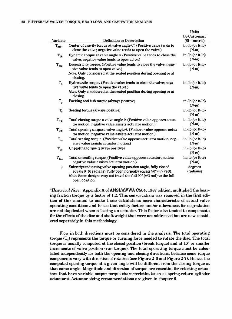
*Historical Note: Appendix A of ANSI/AWWA C504,1987 edition, multiplied the bear- ing friction torque by a factor of 1.2. This conservatism was removed in the first edi- tion of this manual to make these calculations more characteristic of actual valve operating conditions and to see that safety factors and/or allowances for degradation are not duplicated when selecting an actuator. This factor also tended to compensate for the effects of the disc and shaft weight that were not addressed but are now consid- ered separately in this methodology.
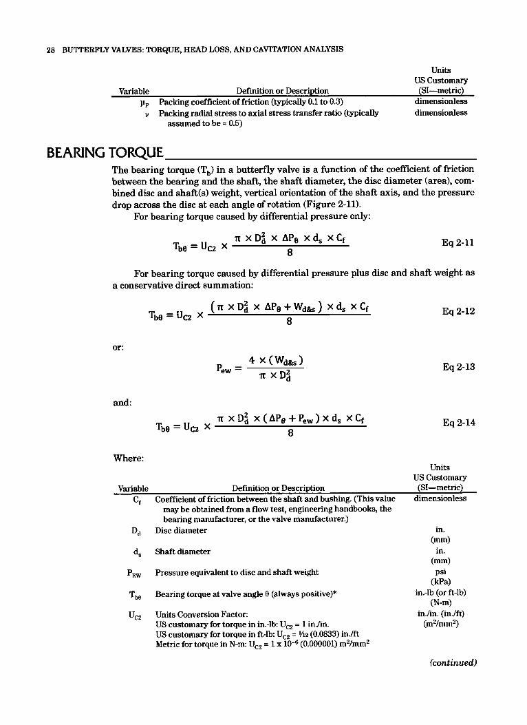
Flow in both directions must be considered in the analysis. The total operating torque (T,) represents the torque or turning force needed to rotate the disc. The total torque is usually computed at the closed position (break torque) and at 10" or smaller increments of valve position (run torque). The total operating torque must be calcu- lated independently for both the opening and closing directions, because some torque components vary with direction of rotation (see Figure 2-6 and Figure 2-7). Hence, the computed opening torque at a given angle will be different from the closing torque at that same angle. Magnitude and direction of torque are essential for selecting actua- tors that have variable output torque characteristics (such as spring-return cylinder actuators). Actuator sizing recommendations are given in chapter 6.
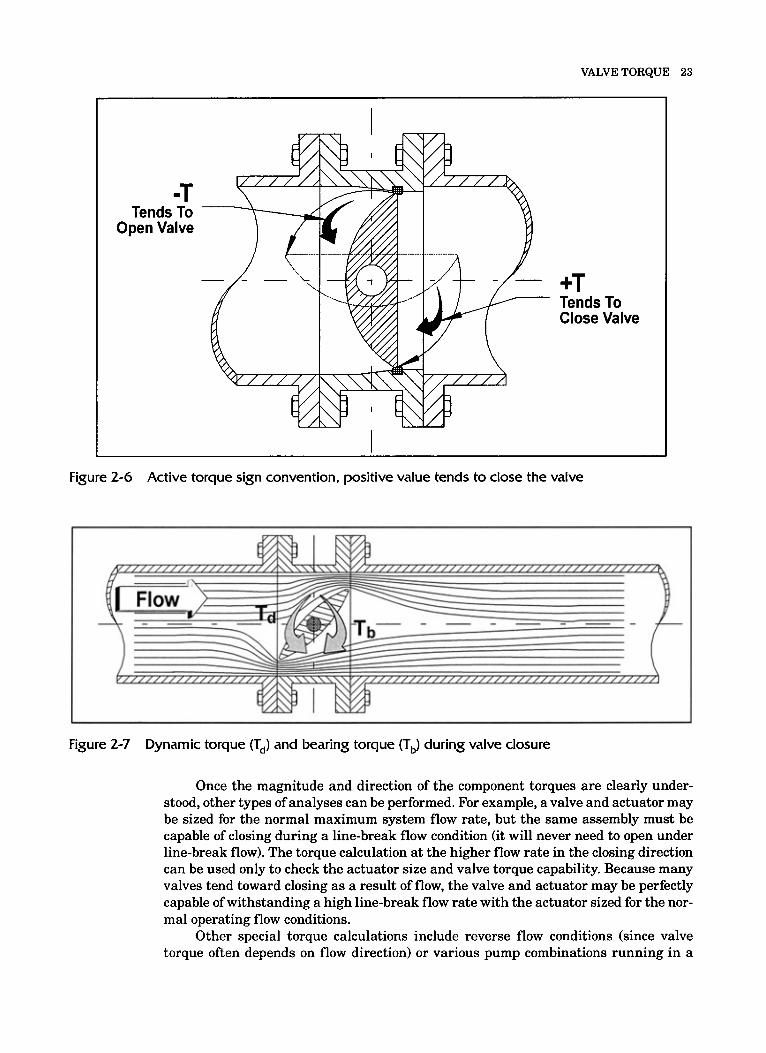
VALVE TORQUE 23
-T Tends To
Open Valve
+T Tends To Close Valve
Figure 2-6 Active torque sign convention, positive value tends to close the valve
Figure 2-7 Dynamic torque (T,) and bearing torque (T,) during valve closure
Once the magnitude and direction of the component torques are clearly under- stood, other types of analyses can be performed. For example, a valve and actuator may be sized for the normal maximum system flow rate, but the same assembly must be capable of closing during a line-break flow condition (it will never need to open under line-break flow). The torque calculation at the higher flow rate in the closing direction can be used only to check the actuator size and valve torque capability. Because many valves tend toward closing as a result of flow, the valve and actuator may be perfectly capable of withstanding a high line-break flow rate with the actuator sized for the nor- mal operating flow conditions.
Other special torque calculations include reverse flow conditions (since valve torque often depends on flow direction) or various pump combinations running in a

24 BUTTERFLY VALVES: TORQUE, HEAD LOSS, AND CAVITATION ANALYSIS
multiple-pump application. For example, when one pump is running in a multiple- pump application (see Figure 2-81, the pump will run further down on its pump curve and develop a flow rate higher than it would when the other pumps are operating. This higher flow rate can cause higher valve torques and stall the motor actuator.
Individual torque components are discussed in detail in the following sections.
SEATING TORQUE In symmetric and single-offset valves, the seating torque (T,) is caused by the friction and interference between the butterfly valve's rubber seat and the mating surface, as shown in Figure 2-9. In double- and triple-offset designs, the seating torque may also be based on the seat load necessary to provide the desired level of seat tightness. Seat- ing torque is a function of many factors, including seat type, material, valve size, fluid temperature, and pressure drop across the disc. The total effect must be determined by tests. Given that all other factors are identical, seating torque is normally proportional to the square of the disc diameter. This formula is derived from first-principles equa- tions and integrated around the perimeter of the disc. This derivation is not included.
Because many seat designs have essentially constant and pressure independent friction coefficients while other seat designs are pressure assisted and friction (load) may increase with applied pressure, two separate seating coefficients are given in the formula. The C,, coefficient is the constant or pressure independent seating coefficient, and the C,, coefficient is the pressure dependent seating coefficient. For a given valve design, either of these may be zero. For example, throttling valves that do not have seats do not have a seating torque.
Where: Units
US Customary Variable Definition or Description (SI-metric)
C,, Constant or pressure independent coefficient of seating torque* lb/in. ( N m
C,,
D, Disc diameter
Pressure dependent coefficient of seating torque*
T, Seating torque (always positive)
U,, Units Conversion Factor: US customary for torque in in.-lb U,, = 1 in./in. US customary for torque in ft-lb U,, = 1/12 (0.0833) in./ft Metric for torque in N-m: U,, = 1 x Maximum pressure drop (or loss) across the closed valve or total
(0.000001) m2/mm2 AP,,,
system with valve closed
lb/in./psi (N/m/kPa)
in. (mm)
in.-lb (or ft-lb) (N-m)
in./in. (in./ft) (m2/mm2)
psid (kP4
"Note: For torque seated (double-offset) valves, the coefficients may be based on the torque required to reach the required pressure and leakage rate.

VALVE TORQUE 25
Figure 2-8 Multiple-pump installation
Figure 2-9 Seating torque (T,)
Seating torque (T,) is always positive because it opposes any disc movement. The effects of seat cleanliness, aging, and degradation are not usually included in the seat- ing coefficient. The test used to determine the seating coefficient (discussed in chap- ter 5 ) is based on a new seat. Manufacturers may apply a safety factor or in-service

26 BUTTERFLY VALVES: TORQUE, HEAD LOSS, AND CAVITATION ANALYSIS
degradation factor to the seating coefficient or the calculated seating torque to account for long-term service conditions.
The pressure dependent coefficient (C ) represents the change in torque in seat designs that are pressure assisted or otherwise variable based on the operating differ- ential pressure. Seat designs that are not affected by pressure differential may have a C, value of zero.
If the torque required to seat and the torque required to unseat are substantially different, separate seating coefficients and unseating coefficients can be developed in a similar manner using:
S?
Eq 2-8
Where: Units
US Customary Variable Definition or Description (SI-metric)
C,,, Constant or pressure independent coefficient of unseating torque* lb/in. "1
C,, Pressure dependent coefficient of unseating torque*
D, Disc diameter
T,, Unseating torque (always positive)
U,, Units Conversion Factor: US customary for torque in in.-lb U,, = 1 in./in. US customary for torque in ft-lb U,, = 1/12 (0.0833) in./ft Metric for torque in N-m: U,, = 1 x Maximum pressure drop (or loss) across the closed valve or total
(0.000001) m2/mm2 AP,,,
system with valve closed
lb/in./psi (N/m/kPa)
in. (mm)
in.-lb (or ft-lb) (N-m)
in./in. (in./ft) (m2/mm2)
*Note: For torque seated (double-offset) valves, the coefficients may be based on the torque required to reach the required pressure and leakage rate.
PACKING AND HUB TORQUE Packing torque (T,) is caused by friction between the shaft seal (packing) and the valve shaft. The hub seal torque is caused by friction between the disc and/or shaft and the body hub seal where the shaft penetrates the pressure boundary (hub) (see Figure 2-10). These are often considered as a single packing torque value. This value is frequently determined by testing and may be given by valve size, shaft diameter, a constant times the shaft diameter, or other formulation.
Packing and hub seal torque (T,) is always positive, because it opposes any disc movement. This value is usually a small component of total torque and is often ignored on larger valves. When the shaft seal is of the O-ring type or V-packing type, this com- ponent of torque is not significant and may be ignored. However, over-tightening of the shaft packing bolts or studs can cause a significant packing torque increase. Consult the valve manufacturer for packing adjustment instructions and recommendations. In some cases, this torque may be considered as a component of seating torque or of other frictional components of torque and may be assumed to be zero.

VALVE TORQUE 27
Shaft /- Packing Bolts
Packing Follower
Figure 2-10 Packing a n d h u b seal torque (T,)
Many packing manufacturers provide packing friction ranges and calculation procedures. Some typical packing torque calculations that may be used are:
or for chevron-type packing: 3 XP, x TC x u x H, x p, xd:
4 Tp = Ucl X
Where:
Eq 2-9
Eq 2-10
Units US Customar-v
Variable Definition or Description (SI-metric) Cpck Packing coefficient lb/in.
Shaft diameter
Packing height
Pressure class or maximum design pressure (the greater of)
Packing and hub seal torque (always positive)
Units Conversion Factor: US customary for torque in in.-lb: U,, = 1 in./in. US customary for torque in ft-lb: U,, = 1/12 (0.0833) in./ft Metric for torque in N-m: U,, = 1 x (0.001) m/mm
(N/m) in.
(mm) in.
(mm) dimensionless
(01. Psigl in.-lb (or ft-lb)
(N-m) in./in. (in./ft)
(m/mm)
(continued)
28 BUTTERFLY VALVES: TORQUE, HEAD LOSS, AND CAVITATION ANALYSIS
Units US Customary
Variable Definition or Description (SI-metric) pp Packing coefficient of friction (typically 0.1 to 0.3) dimensionless v Packing radial stress to axial stress transfer ratio (typically dimensionless
assumed to be = 0.5)
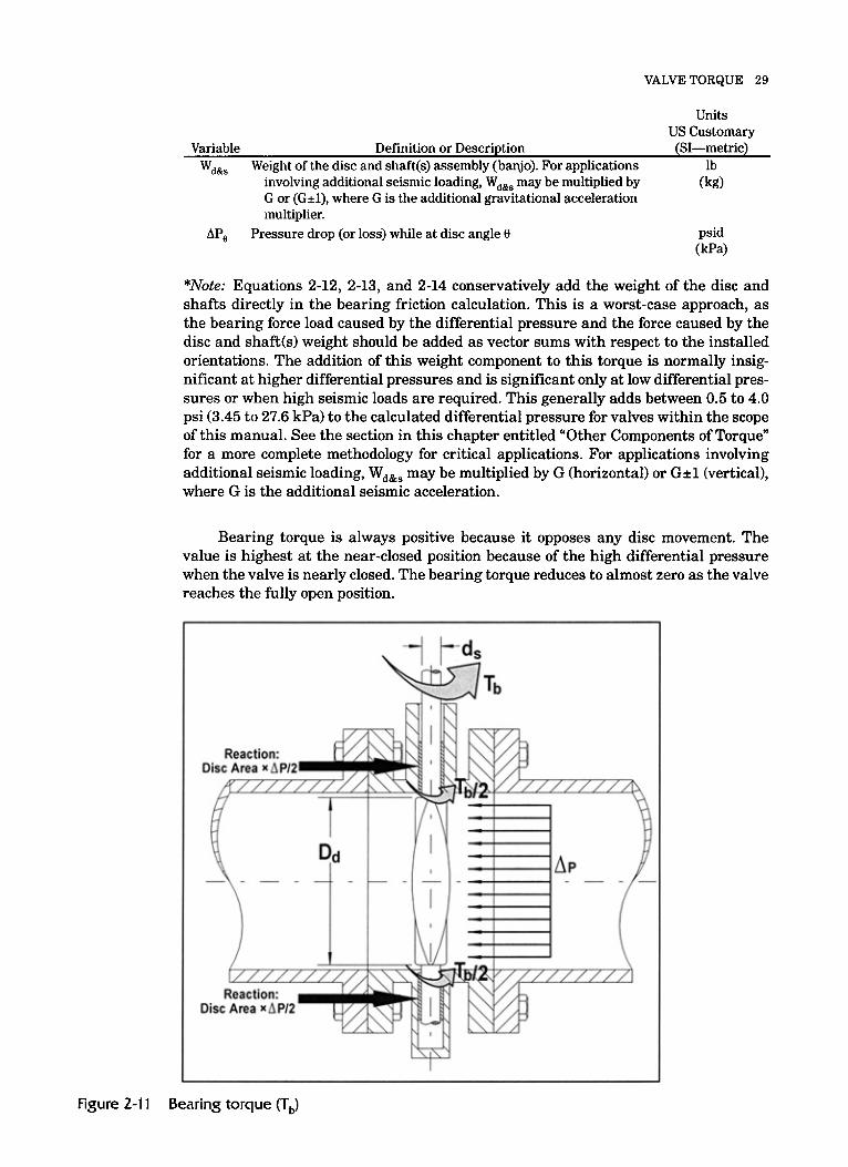
BEARING TORQUE The bearing torque (T,) in a butterfly valve is a function of the coefficient of friction between the bearing and the shaft, the shaft diameter, the disc diameter (area), com- bined disc and shaft(s) weight, vertical orientation of the shaft axis, and the pressure drop across the disc at each angle of rotation (Figure 2-11).
For bearing torque caused by differential pressure only:
Eq 2-11
For bearing torque caused by differential pressure plus disc and shaft weight as a conservative direct summation:
or:
and:
Eq 2-12
Eq 2-13
Eq 2-14
Where: Units
US Customary Variable Definition or Description (SI-metric) - Coefficient of friction between the shaft and bushing. (This value dimensionless
may be obtained from a flow test, engineering handbooks, the bearing manufacturer, or the valve manufacturer.)
Disc diameter
Shaft diameter
Pressure equivalent to disc and shaft weight
Bearing torque at valve angle 0 (always positive)*
Units Conversion Factor: US customary for torque in in.-lb U,, = 1 in./in. US customary for torque in ft-lb: U,, = 1/12 (0.0833) in./ft Metric for torque in N-m: U,, = 1 x (0.000001) m2/mm2
in. (mm)
in. (mm) psi
(kP4 in.-lb (or ft-lb)
(N-m) in./in. (in./ft)
(m2/mm2)
(continued)
VALVE TORQUE 29
Units US Customary
lb (kg)
Variable Definition or Description (SI-metric) Wdsls Weight of the disc and shaft(s) assembly (banjo). For applications
G or (Gil), where G is the additional gravitational acceleration multiplier.
involving additional seismic loading, W,,, may be multiplied by
AP, Pressure drop (or loss) while at disc angle 8 psid (kPa)
*Note: Equations 2-12, 2-13, and 2-14 conservatively add the weight of the disc and shafts directly in the bearing friction calculation. This is a worst-case approach, as the bearing force load caused by the differential pressure and the force caused by the disc and shaft(s) weight should be added as vector sums with respect to the installed orientations. The addition of this weight component to this torque is normally insig- nificant at higher differential pressures and is significant only at low differential pres- sures or when high seismic loads are required. This generally adds between 0.5 to 4.0 psi (3.45 to 27.6 kPa) to the calculated differential pressure for valves within the scope of this manual. See the section in this chapter entitled “Other Components of Torque” for a more complete methodology for critical applications. For applications involving additional seismic loading, Wa&s may be multiplied by G (horizontal) or G d (vertical), where G is the additional seismic acceleration.
Bearing torque is always positive because it opposes any disc movement. The value is highest at the near-closed position because of the high differential pressure when the valve is nearly closed. The bearing torque reduces to almost zero as the valve reaches the fully open position.
D
‘B
Dis
Figure 2-1 1 Bearing torque (T,)

30 BUTTERFLY VALVES: TORQUE, HEAD LOSS, AND CAVITATION ANALYSIS
CENTER OF GRAVITY TORQUE Center of gravity torque (Tcg) is caused by the offset center of gravity of the disc. This torque occurs when the valve shaft is located in or near the horizontal plane, and it is a function of the disc position and weight as well as the distance from the axis of rotation to the center of gravity (see Figure 2-12). With a horizontal valve shaft and a horizontal pipeline, this torque is greatest when the center of gravity location is situ- ated on the pipeline axis. This torque varies considerably based on disc design and the center of gravity location. This torque may be assumed as insignificant or may be included as a worst-case constant maximum value throughout the valve travel by setting COS(0 + y) equal to one (1) throughout the valve travel. See section on Other Torque Components and Figure 2-21 and Figure 2-22 for more complete installation details for use in critical applications.
For horizontal shaft and pipe axis, the basic equation is:
T~~ = uCi x sc x w, x c, x cos(e + y > Eq 2-15
Where: Units
US Customary
in. Variable Definition or Description (SI-metric)
Cg
S , Sign convention variable: dimensionless
Valve disc center of gravity distance from shaft centerline (mm)
For torque active components: +I when the torque tends to close the valve, or -1 when the torque tends to open the valve.
For center of gravity torque: the sign convention variable is +1 when the center of gravity is above the horizontal when the disc is in the full open position, or -1 when the center of gravity is below the horizontal when disc is full open.
For torque transmitted to the actuator: a positive value when valve shaft torque opposes actuator motion, or negative value when valve shaft torque assists actuator motion (actuator is acting as a brake).
U,, Units Conversion Factor: in./in. (in./ft) US customary for torque in in.-lb U,, = 1 in./in. US customary for torque in ft-lb U,, = !h (0.0833) in./ft Metric for torque in N-m: U,, = 1 x Center of gravity torque at valve angle 0. (Positive value tends to
(m/mm)
(0.001) m/mm
Tcge in.-lb (or ft-lb) (N-m) close the valve; negative value tends to open the valve.)
W, Weight of valve disc lb (kg)
y
8
Center of gravity offset angle (nonsymmetric disc designs) (See Fig-
Valve opening position angle, closed = 0" (0 radians); full open = 90"
degrees ure 2-12) (radians)
degrees (d2 radians) (See Figure 2-12) (radians)

VALVE TORQUE 31
Center of Gravity Torque x
\ VERTICAL’ e -7 Figure 2-1 2 Center of gravity torque (TCJ
For installations where the pipe axis and shaft axis are known to be in other ori- entations, see the section later in this chapter entitled “Other Components of Torque” for a more complete methodology for critical applications.
HYDROSTATIC TORQUE Hydrostatic torque (T,) is caused by the static elevation head of the water acting against one side of the disc when the other side of the disc is empty (refer to Figure 2-13 and Figure 2-23). This torque component occurs when pipe axis and shaft axis are at or near horizontal (pipe and shaft angles greater than zero). The sign conven- tion variable may be assigned to indicate when assisting or opposing actuator motion or it might be considered to oppose both operating directions as a worst-case assump- tion. This torque component only occurs when there is no flow and the valve is seated and one side of the line is empty.
When the water pressure forces on the disc are integrated across the surface of the disc, it can be replaced with a single force vector, Fresultant, as shown in Figure 2-13. Although not used in the derivation of the formula, this provides a clearer visualiza- tion of the effect the fluid pressure load. This derivation is not included.
When valve shaft and pipe axis are horizontal:
Th = s, X ucl X - x (34 x (1+ ‘2 ) (in US customary units) Dd Eq 2-16 5.333

32 BUTTERFLY VALVES: TORQUE, HEAD LOSS, AND CAVITATION ANALYSIS
or:
Or for cold water where p = 62.4 lb/ft3:
‘2 ) (in US. customaryunits) (l+ Dd Eq 2-18
Th = sc X ucl X 0.0017726 X ( Dd)4 X
For cold water where p = 1,000 kg/m3:
‘2 ) (in SI [metric] units) (l+ Dd Eq 2-19
Th = Sc X 481.322 X (Ucl X Dd )4 X
Where: Units
US Customary Variable Definition or Description (SI-metric)
Dd Disc diameter
Gravitational constant Acceleration due to gravity, 32.2 ft/sec2 (9.81m/sec2) Sign convention variable: For torque active components: +1 when the torque tends to close
the valve, or -1 when the torque tends to open the valve. For center of gravity torque: the sign convention variable is +1
when the center of gravity is above the horizontal when the disc is in the full open position, or -1 when the center of grav- ity is below the horizontal when disc is full open.
valve shaft torque opposes actuator motion, or negative value when valve shaft torque assists actuator motion (actuator is acting as a brake).
Hydrostatic torque. (Positive value tends to close the valve; nega- tive value tends to open the valve.)
Note: Only considered at the seated position during opening or at closing.
Units Conversion Factor: US customary for torque in in.-lb U,, = 1 in./in. US customary for torque in ft-lb U,, = !42 (0.0833) in./ft Metric for torque in N-m: Uc, = 1 x lo3 (0.001) m/mm Disc lateral offset. Note: s2 equals 0 for symmetric or single-offset disc designs. Sign Convention Note: For hydrostatic torque, e2 is positive
For torque transmitted to the actuator: a positive value when
when oriented above the valve centerline, and negative when oriented below the valve centerline.
See Figure 2-3. Fluid density Note: Standard water density is considered as 62.4 lb/ft3
(1,000 kg/m3)
in. (mm) ft/sec2
(m/sec2) dimensionless
in.-lb (or ft-lb) “4
in./in. (in./ft) (m/mm)
in. (mm)
lb/ft3 (kg/m3>

VALVE TORQUE 33
I
Figure 2-13 Hydrostatic torque
Hydrostatic torque is proportional to disc diameter raised to the fourth power and may become significant on large valves. Assuming shaft and pipe horizontal, a 12411. (300-mm) valve has a negligible hydrostatic torque of 37 in.-lb (3.1 ft/lb, 4.2 N-m); a 36-in. (900-mm) valve has a substantial hydrostatic torque of 2,975 in.-lb (247.9 ft-lb, 336 N-m); and a 120-in. (3,000-mm) valve has a very large hydrostatic torque of 367,200 in.-lb (30,600 ft-lb, 41,500 N-m).
DYNAMIC TORQUE Dynamic torque (T,) is a flow-induced torque determined as a function of valve geo- metry, flow rate, and valve position (Figure 2-14).
Tde = Uc2 X Cto X Di X Ape Eq 2-20
Where: Units
US Customary
dimensionless Definition or Description (SI-metric) Variable
C,,
Dd* Disc diameter in.
T,,, in.-lb (or ft-lb)
U,, Units Conversion Factor: in./in. (in./ft)
Coefficient of dynamic torque at valve angle 0 (positive value tends to close valve)
(mm)
(N-m)
(m2/mm2)
Dynamic torque at valve angle 8. (Positive value tends to close the valve; negative value tends to open valve.)
US customary for torque in in.-lb: U,, = 1 in./in. US customary for torque in ft-lb: U,, = %2 (0.0833) in./ft Metric for torque in N-m: U,, = 1 x 10⁻⁶ (0.000001) m2/mm2
AP, Pressure drop (or loss) while at disc angle 8
*The nominal valve diameter (D) may be used when the D, is unknown. This increases the uncertainty but is generally larger than the actual disc diameter.

34 BUTTERFLY VALVES: TORQUE, HEAD LOSS, AND CAVITATION ANALYSIS
Figure 2-14 Dynamic torque (T,) for a symmetrical disc
The maximum coefficient of dynamic torque (which reflects a constant pressure drop at all travel positions) occurs at approximately the 65" to 80" open position. In contrast, the maximum total dynamic torque (the summation of all operating torque requirements) normally occurs at an intermediate travel position between 0" (closed) and 50" (open) where the differential pressure is high (that is, pressure drop varies with valve position). Pressure drop and dynamic torque are dependent on the charac- teristics of the piping system and cannot be assumed without a system analysis.
Dynamic torque coefficients for a symmetrical disc are normally independent of flow direction (see Figure 2-15). They are functions of disc geometry, valve travel, and pressure drop.
Dynamic torque coefficients for an offset disc, also shown in Figure 2-15, depend on flow direction through the valve as well as disc geometry, valve travel, and pres- sure drop across the disc. The dynamic torque coefficient at the open position may be negative (giving the disc a tendency to open) when the valve is installed with the seat upstream. The offset disc torque coefficient can also change sign near the 85" posi- tion. If the valve is positioned at an angle where torque direction is unstable (where C, crosses zero) for extended periods, damage caused by vibration may occur, and pro- longed operation in this valve position should be avoided.
Although the dynamic torque coefficients reach maximum at about 70" to 80"open (as shown in Figure 2-15), the total valve opening torque reaches maximum at a much lower angle (about 35") as shown in Figures 2-17 and 2-18). Figures 2-19 and 2-20 demonstrate how the total actuator torque changes during the closing stroke. In Fig- ure 2-16 , dynamic torque is highest at c45" open because the pressure drop (AP) is an order of magnitude higher there than at 80" open, and dynamic torque is the product of both the dynamic torque coefficient and the pressure drop (see Eq 2-20):
Eq 2-20
Because dynamic torque is proportional to the disc diameter cubed, it often becomes the largest torque on valves greater than about 20 in. (500 mm) for velocities up to 16 ft/sec (5.2 m/sec) and above. On smaller valves, typically 6 in. (150 mm) and less, dynamic torque can be ignored, and the actuator may be sized for seating, bear- ing, and packing torque unless the maximum velocity exceeds 16 ft/sec (5.2 m/sec).
Because the dynamic torque is dependent on the pressure drop during the valve travel, the dynamic torque coefficient and the flow coefficients must be from the same valve data set and not mixed with coefficients from other valves.
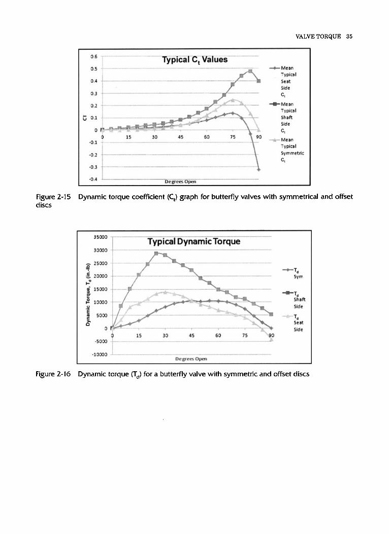
VALVE TORQUE 35
0.6
0.5
0.4
0.3
0.2
0.1
0
-0.1
-0.2
-0.3
.i ................................................... I .I ........................................................................................
............................................ ............................................. i -t-.
6 15 30 45 60 75 0
?
-+Mean Typica I Seat Side
c, +Mean
Typical Shaft Side
ct w&- Mean
Tvpical Symmetric
ct
r j e ; g r ~ ~ p n ......................................................................... -0.4
Figure 2-15 discs
Dynamic torque coefficient (C,) graph for butterfly valves with symmetrical and offset
3 5030 ....... ...........................................
Typical Dynamic Torque 30030 ..........................
-Td Shaft
Figure 2-16 Dynamic torque (T,) for a butterfly valve with symmetric and offset discs

36 BUTTERFLY VALVES: TORQUE, HEAD LOSS, AND CAVITATION ANALYSIS
40.000
30,000
20.000
10,000
0
...........
.................................
+ " I a
30 45 60 75 PD
-Total Symmetric
+Total Shaft Side Flow
-a,- Total Seat Side Flow
Figure 2-17 Total opening torque (Tto) for a 20-in. (500 mm) to 30-in. (750 mm) butterfly valve with symmetric and offset discs
I 1,800,000
1,600,000
1,400,000
1,200,000 e ;. 1,000,000
5 eo0,ooo e 8 600,000 r c" 400,000 u)
200,000
0
-200.000
.- -
-f. Typical 78 in. to 96 in. Total Opening Required Torque - l_llllllllll
.............................
.........
+Total Shaft Side Flow
c - Total Seat Side
Figure 2-18 Total opening torque (Tto) for a 78-in. (2,000 mm) to %-in. (2,400 mm) butterfly valve with symmetric and offset
SHAFT OFFSET OR ECCENTRICITY TORQUE Shaft offset or eccentricity torque for a butterfly valve with a double-offset shaft is shown in Figure 2-19. This design is subject to an additional torque related to the lat- eral offset or eccentricity and the hydrostatic differential force on the disc. This torque only applies at the full closed or seated position as it becomes a part of the dynamic torque coefficients and calculations at other disc positions. This torque is often treated as a positive value but may be given a sign if the seating and unseating torque compo- nents are to be considered individually.

VALVE TORQUE 37
Typical 20 in. to 30 in. Total Closing Required Torque
TQbl Symmetric
+Total Shaft Side Flow
MW Total Seat Side Flow
Self closing torque
I -30000 UegreUpa,
Figure 2-19 Total closing torque (TJ for a 20-in. (500 mm) to 30-in. (750 mm) butterfly valve with symmetric and offset discs
IT x D: x z2 x AP, 4
T,,, = Sc X Uc;! X Eq 2-21
Where: Units
US Customary Variable Definition or Description (SI-metric)
Disc diameter in.
Sign convention variable: For torque active components: +1 when the torque tends to close the
valve, or -1 when the torque tends to open the valve. For center of gravity torque: the sign convention variable is +1 when
the center of gravity is above the horizontal when the disc is in the full open position, or -1 when the center of gravity is below the horizontal when disc is full open.
For torque transmitted to the actuator: a positive value when valve shaft torque opposes actuator motion, or negative value when valve shaft torque assists actuator motion (actuator is acting as a brake).
Eccentricity torque. (Positive value tends to close the valve; negative value tends to open valve.)
Note: Only considered at the seated position during opening or at closing.
Units Conversion Factor: US customary for torque in in.-lb U,, = 1 in./in. US customary for torque in ft-lb Uc, = 1/12 (0.0833) in./ft Metric for torque in N-m: U,, = 1 x Pressure drop (or loss) across the valve, general form
(0.000001) m2/mm2
Disc lateral offset Note: E, equals 0 for symmetric or single-offset disc designs. Sign Convention Note: For hydrostatic torque, E, is positive when
oriented above the valve centerline, and negative when oriented below the valve centerline.
See Figure 2-3.
(mm) dimensionless
in.-lb (or ft-lb) "-4
in./in. (in./ft) (mz/mm2)

38 BUTTERFLY VALVES: TORQUE, HEAD LOSS, AND CAVITATION ANALYSIS
Figure 2-20 Total closing torque (T,) for a 78-in. (2,000 mm) to 96-in.(2,400 mm) butterfly valve with symmetric and offset discs
t- Figure 2-21 Shaft offset or eccentricity torque
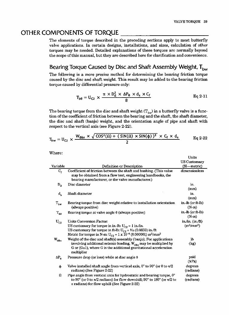
VALVE TORQUE 39
OTHER COMPONENTS OF TORQUE The elements of torque described in the preceding sections apply to most butterfly valve applications. In certain designs, installations, and sizes, calculation of other torques may be needed. Detailed explanations of these torques are normally beyond the scope of this manual, but they are described here for clarification and convenience.
Bearing Torque Caused by Disc and Shaft Assembly Weight, TbW The following is a more precise method for determining the bearing friction torque caused by the disc and shaft weight. This result may be added to the bearing friction torque caused by differential pressure only:
Eq 2-11
The bearing torque from the disc and shaft weight (Tbw) in a butterfly valve is a func- tion of the coefficient of friction between the bearing and the shaft, the shaft diameter, the disc and shaft (banjo) weight, and the orientation angle of pipe and shaft with respect to the vertical axis (see Figure 2-22).
Eq 2-22 Wd, x J COSz(fl) + (SIN(fl) x SIN(@) )' x Cf x d, Tbw = u C Z 2
Where: Units
US Customary
dimensionless Variable Definition or Description (SI-metric)
C, Coefficient of friction between the shaft and bushing. (This value may be obtained from a flow test, engineering handbooks, the bearing manufacturer, or the valve manufacturer.)
Disc diameter
Shaft diameter
Bearing torque from disc weight relative to installation orientation
Bearing torque at valve angle 8 (always positive) (always positive)
Units Conversion Factor: US customary for torque in in.-lb Uc, = 1 in./in. US customary for torque in ft-lb: U,, = 1/12 (0.0833) in./ft Metric for torque in N-m: U,, = 1 x Weight of the disc and shaft(s) assembly (banjo). For applications
involving additional seismic loading, Wdsls may be multiplied by G or (Gil), where G is the additional gravitational acceleration multiplier
(0.000001) m2/mm2
Pressure drop (or loss) while at disc angle 8
Valve installed shaft angle from vertical axis, 0" to 90" (or 0 to n/2 radians) (See Figure 2-22)
Pipe angle from vertical axis for hydrostatic and bearing torque, 0" to 90" (or 0 to n/2 radians) for flow downhill; 90" to 180" (or n/2 to n radians) for flow uphill (See Figure 2-22)
in. (mm)
in. (mm)
in.-lb (or ft-lb) (N-m)
in.-lb (or ft-lb) (N-m)
in./in. (in./ft) (mz/mm2)
lb (kg)
psid (kPa)
degrees (radians) degrees (radians)
40 BUTTERFLY VALVES: TORQUE, HEAD LOSS, AND CAVITATION ANALYSIS
I---- Pipe Anale Valve Shaft
SECTION A-A
Valve Shaft
/
I
I
SECTION A-A
Figure 2-22 Bearing torque caused by disc and shaft(s) weight orientation angles
The vector summation with the total bearing friction torque from both the loads caused by differential pressure and disc and shaft(s1 weight is as follows:
Tbtota10 = ( TbO -k T b w Eq 2-23
Where: Units
US Customary Variable Definition or Description (SI-metric)
TbtoulO in.-lb (or ft-lb) relative to installation orientation (always positive) (N-m)
T,, in.-lb (or ft-lb) (always positive) (N-m)
T,, in.-lb (or ft-lb) (N-m)
Total bearing torque at valve angle 8 with addition of disc weight
Bearing torque from disc weight relative to installation orientation
Bearing torque at valve angle 8 (always positive)

VALVE TORQUE 41
Center of Gravity Torque for Installed Orientation, Tcge For installations where the pipe axis and shaft axis are known to be in other orienta- tions, the following equations may be used.
Eq 2-24
Where: Units
US Customary Variable Definition or Description (SI-metric)
Cg Valve disc center of gravity distance from shaft centerline
Sign convention variable: For torque active components: +1 when the torque tends to close
the valve, or -1 when the torque tends to open the valve. For center of gravity torque: the sign convention variable is +1
when the center of gravity is above the horizontal when the disc is in the full open position, or -1 when the center of gravity is below the horizontal when disc is full open.
valve shaft torque opposes actuator motion, or negative value when valve shaft torque assists actuator motion (actuator is acting as a brake).
Center of gravity torque at valve angle 8. (Positive value tends to close the valve; negative value tends to open the valve.)
Units Conversion Factor: US customary for torque in in.-lb: U,, = 1 in./in. US customary for torque in ft-lb U,, = %2 (0.0833) in./ft Metric for torque in N-m: U,, = 1 x Weight of valve disc
For torque transmitted to the actuator: a positive value when
(0.001) m/mm
Pipe angle from vertical axis for center of gravity relative to seat location, 0" to 90" (or 0 to n/2 radians) when seated position is above horizontal; >90" to 180" (or n/2 to n radians) when seated position is below horizontal. (See Figure 2-23)
Center of gravity offset angle (nonsymmetric disc designs). (May also include an adjustment for valve designs where the
seating angle is not perpendicular to the pipe axis.) (See Figure 2-23)
Valve opening position angle, closed = 0" (0 radians); full open = 90" (n/2 radians) (See Figure 2-23)
Valve installed shaft angle from vertical axis, 0" to 90" (or 0 to n/2 radians) (See Figure 2-24)
in. (mm)
dimensionless
in.-lb (or ft-lb) (N-m) in./in. (in./ft)
(m/mm)
lb (kg)
degrees (radians)
degrees (radians)
degrees (radians) degrees (radians)

42 BUTTERFLY VALVES: TORQUE, HEAD LOSS, AND CAVITATION ANALYSIS
I 1
Seat End
VERTICAL^
Figure 2-23 Center of gravity torque pipe angle definition
Figure 2-24 Valve shaft and pipe orientation from vertical axis for center of gravity torque

VALVE TORQUE 43
Hydrostatic Torque for Installed Orientation, T, When the valve shaft is not vertical and the pipe axis is not horizontal but known, the following equations may be used:
Eq 2-25 -
(in US customary units)
For cold water where p = 62.4 lb/ft3:
Th = s, X ucl X 0.0017726 X (Dd )4 X (SIN(+) + E2 ) X SIN(C4) Eq 2-26 Dd
(in US customary units)
For cold water where p = 1,000 kg/m3:
Th = s, X 481.322 X (uc- X Dd)4 X 8 X ~2
SIN(@) + ) X SIN(a) Eq 2-27 ( Dd (in SI [metric] units)
Where: Units
US Customary Variable Definition or Description (SI-metric)
Disc diameter in.
Gravitational constant Acceleration due to gravity, 32.2 ft/sec2 (9.81m/sec2) Sign convention variable: For torque active components: +1 when the torque tends to close
the valve, or -1 when the torque tends to open the valve. For center of gravity torque: the sign convention variable is +1 when
the center of gravity is above the horizontal when the disc is in the full open position, or -1 when the center of gravity is below the horizontal when disc is full open.
For torque transmitted to the actuator: a positive value when valve shaft torque opposes actuator motion, or negative value when valve shaft torque assists actuator motion (actuator is acting as a brake).
Hydrostatic torque. (Positive value tends to close the valve; nega- tive value tends to open the valve.)
Note: Only considered at the seated position during opening or at closing.
Units Conversion Factor: US customary for torque in in.-lb U,, = 1 in./in. US customary for torque in ft-lb Ucl = 1/12 (0.0833) in./ft/ Metric for torque in N-m: Ucl = 1 x Disc lateral offset Note: c2 equals 0 for symmetric or single-offset disc designs. Sign Convention Note: For hydrostatic torque, E~ is positive when
oriented above the valve centerline, and negative when oriented below the valve centerline.
(0.001) m/mm
See Figure 2-3. Fluid density Note: Standard water density is considered as 62.4 lb/ft3
(mm) fWsec2
(m/sec2) Dimensionless
in.-lb (or ft-lb) (N-m)
in./in. (in./foot) (m/mm)
(continued)

44 BUTTERFLY VALVES: TORQUE, HEAD LOSS, AND CAVITATION ANALYSIS
Units US Customary
Valve installed shaft angle from vertical axis, 0" to 90" (or 0 to n/2 degrees radians) (See Figure 2-25) (radians)
Pipe angle from vertical axis for hydrostatic and bearing torque, 0" degrees to 90" degrees (or 0 to n/2 radians) for flow downhill; 90" to 180" (radians) (or n/2 to n radians) for flow uphill. (See Figure 2-25)
Variable Definition or Description (SI-metric) 4
61
If the valve shaft angle, +, equals zero (shaft vertical) or pipe angle, a, equals zero (pipe vertical), then T, = 0.
Buoyancy Torque Another component of torque is generated by the buoyancy force of water displaced by the disc acting vertically upward at its center of buoyancy. This torque is essentially opposite of the center of gravity torque and is generally low enough to be ignored except in very large (e.g., 60-in. [1,500-mml) low-pressure (e.g., 25-psig [172-kPal) designs with hollow disc structures. This methodology is similar to the weight and center of gravity torque.
Thrust Bearing Torque This component of torque is generated by frictional resistance of the valve thrust bear- ing, which centers the disc axially along the shaft while supporting the disc and shaft weight, and the shaft thrust caused by internal pressure (also known as the piston effect or shaft ejection thrust). This torque is generally negligible except in very-high-pressure designs (e.g., 250 psig l1.72 MPal) and high-friction thrust bearing designs.
Upstream Flow Disturbances Flow and Asymmetric Flow Distributions Unusual installations-for example, where a butterfly valve is mounted downstream of elbows, pumps, or other valves-may cause unusually high dynamic torques if the valves are not oriented properly, as chapter 6 explains. If a special orientation is required, flow tests of the actual piping configuration, or a model of it, can be conducted to determine an applicable set of flow and torque coefficients. Also, some researchers have developed approximate methods for estimating the amount of dynamic torque increase in relation to upstream elbows at various installed orientations.
SYSTEM CHARACTERISTICS System characteristics must be known to calculate the flow, AP, and torque for each valve position as the valve is opened or closed. Pressure drop in a piping system is caused by friction losses in the pipe, valves, and other components of the system. The system flow rate increases or decreases with changes in the valve position. As the flow rate increases or decreases, the friction losses in the remainder of the system change in relation to the square of the change in flow rate. For example, reducing the flow rate by one-half causes the friction loss in the pipe to decrease to one-fourth of the original value. Given this relationship, the system design data and the initial flow parameters must be known in order to determine the pressure drop across the valve and the torque values as the valve position changes.

VALVE TORQUE 45
Valve Shaft
HORIZONTAL
SECTION A-A
, SECTION A-A
I I
Figure 2-25 Valve shaft and pipe orientation from vertical axis for hydrostatic and bearing torque
The type of information needed for a complete analysis is as follows:
1. Description of the system head source (constant or variable): If the sys- tem head is variable, the pump curve should be included. If the pump curve is not available, a constant head source with a source pressure equal to the differential pressure across the valve will be assumed.
2. Maximum pressure differential: Maximum differential pressure across the closed valve.
3. Maximum design flow rate: Maximum design flow through the piping system through the fully open valve.
4. System pressure drop: System pressure drop at the design flow rate. If this information is not provided, a pressure drop equal to the closed pressure differen- tial across the valve is assumed.
SYSTEM ANALYSIS AND EXAMPLE CALCULATIONS Figure 2-26 shows a basic diagram of important relationships. Calculations involve the following variables:

46 BUTTERFLY VALVES: TORQUE, HEAD LOSS, AND CAVITATION ANALYSIS
Figure 2-26
AH = Head loss between any two points in a system, feet of water A P = Pressure drop (or loss) between any two points in a system, psi K = Resistance coefficient, dimensionless
= Resistance coefficient of valve at full open (go"), dimensionless
g = Gravitational constant (acceleration caused by gravity), ft/sec2 (m/sec2)
D = Valve diameter, in. (mm) V = Velocity of flow, feet per second, ft/sec (m/sec)
The additional variable subscripts that are applied to variables such as C,, Td, T,, AP, AH, or K are:
sys = Subscript indicating system piping and components less the butterfly valve
v = Subscript indicating the butterfly valve 0-90 = Subscript indicating the butterfly valve disc angle
+Variable Equivalent Resistance System MEdd
140
120
Head Source
," d d v I 1 +Constant Head
In Variable Full Open Source
Valve
LOSS Head
He?!iss
Constant -- In fA:!$:Iy6- System c Head --sy5twn
LO55
-Static Head
1 ' 6 0 .-
20
0 0 4 8 12 16
Flow Vekcity fps
Relationship between velocity and head loss in butterfly valves
These methods are based on an equivalent resistance model as graphically shown in Figure 2-26.
CONSTANT HEAD SOURCE METHODOLOGY A typical constant head source application in a water system is the flow of water from an elevated reservoir to a residential water tap. Although the water level in the ele- vated reservoir changes throughout the day, at any given time the supply head (which is the elevation of the water level in the reservoir) is constant regardless of the water flow rate. The sum of all losses in a flow system at any time equals AH,,. When cal- culating the torque of a butterfly valve, the system should be evaluated as two compo- nents: the valve and the system piping. In a system with a constant head source, AH,, can be considered constant for all flow conditions at a given time. When a valve in the system is closed, the maximum differential pressure across the valve (AHMAx) is equal

VALVE TORQUE 47
to the maximum differential across the system (AH,,). The calculation of operating torque for a single butterfly valve in a system assumes that no other variable loss coef- ficient components, such as other valves, are changing in the system during the valve travel. Therefore, the velocity head loss coefficient of all components other than the valve in question can be considered constant and equal to Ksy8. This is the basis of the equivalent resistance system model.
The system can be easily modeled as the maximum shutoff (closed) differential head or differential pressure and the maximum flow rate or velocity are known. (Note: These input values are required by ANSIIAWWA C504-10 and ANSIIAWWA C516-10.) 1. Calculate Ksys using & for a fully open butterfly valve:
2 X g X AHMU Ksys = - Kvso vim
Eq 2-28
Where: Units
US Customary
ftlsec2 (m/sec2)
K,, System flow resistance coefficient (excluding the valve) dimensionless K,, dimensionless
VMAX ft/sec (mlsec)
AH,,, feet of water (meters of water)
AH,,, Head loss across the system feet of water (meters of water)
Variable Definition or Description (SI-metric) g Gravitational constant
Acceleration due to gravity, 32.2 ft/sec2 (9.81m/sec2)
Flow resistance coefficient of valve atfull open (=go", =n/2 radians)
Maximum full open velocity. (Note: Based on nominal valve diam-
Head loss across the closed valve or total system with valve closed
Note: Use of K,, assumes the valve travels 90" to full open.
eter if converted from a quantity flow rate.)
2. The flow velocity through the valve at the valve angle (€0 may be calculated using:
Eq 2-29
Where: Units
US Customary
dimensionless ftlsec
(mlsec)
Variable Definition or Description (SI-metric)
K, Ve
Flow resistance coefficient of the valve at valve angle 0 Approach velocity of fluid flow at valve angle 0
3. Calculate AH,, at the valve angle (0):
Eq 2-30
or:
Eq 2-31

48 BUTTERFLY VALVES: TORQUE, HEAD LOSS, AND CAVITATION ANALYSIS
Where: Units
US Customary Variable Definition or Description (SI-metric)
feet of water (meters of water)
AHve Head loss across the valve at angle 0
4. Calculate AP,, at the valve angle (0):
APvg = 0.4335 X AHve Eq 2-32
or:
Eq 2-33
Where: Units
US Customary
psid (kPa)
Variable Definition or Description (SI-metric)
APve Pressure drop (or loss) across the valve at valve angle 0
5. Calculate dynamic torque Td, at the valve angle (0):
Tde = Uc2 X Cte x Di X Ape
6. Calculate bearing torque Tbe at the valve angle (0):
TC x D ~ X Ape Xd, X C f
8 Tbe = u C 2
Eq 2-20
Eq 2-11
Note: as a direct summation use:
For bearing torque caused by differential pressure plus disc and shaft weight
(TC XD: X APe+Wd&s) Xd, X C f Eq 2-12 8 TbO = uC2
7. Calculate total torque T, at the valve angle for the opening and closing directions:
Using Equations 2-1 and 2-3. Note that the Td torque will be positive in the open- ing direction and negative in the closing direction. 8. Repeat steps 2 through 7 for other valve angles.
CONSTANT HEAD SOURCE-EXAMPLE Given the following information (in US customary units) supplied by the user:
eter single-offset disc, seat side flow. Assume a 244x1. AWWA Class 150B butterfly valve with 24-in. (600 mm) diam-

VALVE TORQUE 49
Maximum head differential (AHMAx) is 150 ft (45.7 m) of water (APMA, = 65 psid
Maximum system flow rate (VMAX) is 12 ft/sec (3.66 m/sec). Valve is installed in a horizontal line with a vertical shaft.
Given the following information supplied by the valve manufacturer:
[448 kPa1).
ds =
T =
D, = P
Tcg =
csc =
csp =
wd&s =
qe from Table 2-1 C, from Table 2-1 C, for a bronze bearing = 0.25 3.00 in. (76 mm) (per ANSUAWWA C504-10) 1,350 in.-lb (113 ft-lb = 153 N-m)
24.0 in. (600 mm)
0
16.0 lb/in. (2,800 N/m)
0.03 lb/in./psi (0.76 N/m/kPa) 450 lb (200 kg)
1. Calculate seating torque:
Ts = uc2 x ( cs, + cs, x APIn,, ) x Ki
Ts = 1 x ( 16 + 0.03 x 65) x 24' = 10,340 in.- lb
2. Calculate
2 x32.2 x150 1 2 2
- 0.3 = 66.78 Ksys =
Eq 2-7
Eq 2-28
3. Calculate 80"
Eq 2-29
2 x32.2 x150 66.78 + 0.41
= 11.99 fps J v80 =
4. Calculate 80"
Eq 2-30
0.41 x 11.99' 2 x 32.2
= 0.92 ft AHvso =

50 BUTTERFLY VALVES: TORQUE, HEAD LOSS, AND CAVITATION ANALYSIS
or:
150 x 0.41 = 0.92 ft
= ( 0.41 + 66.78 )
5. Calculate 80"
or:
APve = 0.4335 X AHve
Ahso = 0.4335 x 0.92 = 0.40 psi
65 x 0.41 = 0.40 psi
= ( 0.41 + 66.78)
6. Calculate 80"
Tde = Uc2 x Cte X Di X Ape
T&O = 1.0 x 0.097 x 243 x 0.40 = 536 in. - lb
7. Calculate 80" (IT XD; X APe+Wd&s) Xd, X C f
8 = u C 2
Eq 2-31
Eq 2-32
Eq 2-33
Eq 2-20:
Eq 2-12:
( 3.1416 x 242 x 0.40 + 450) x 3.0 x 0.25 8
= 110 in. - lb Tb80 = 1.0 x
Note: As the valve shaft is stated as vertical, Eq 2-11 could also be used, which elimi- nates the effect of the disc and shaft weight component.
8. Calculate 80" Total Opening (Run) Torque:
= TbO + TcgO + TdO + Tp
Tt&O = 110 + 0 + 536 + 1,350 = 1,996in.- lb
9. Calculate 80" Total Closing (Run) Torque:
TtcO = TbO - TcgO - TdO + Tp
Eq 2-5
Eq 2-6
Tt&O = 110 + 0 - 536 + 1,350 = 924 in.- lb

VALVE TORQUE 51
Table 2- 1 Calculation data for constant head source example
Valve Ttoe Tke
e % (deg.) Ill
A@e TdO T,, Opening Closing (in.-lb) (in.-lb) (in.-lb) (in.-lb)
[21 [31 161, [GI [41,R, 6 1
90 0.3 -0.3210 12.0 0.7 0.3 -1,290 92 151 2,732
80 0.4 0.0969 12.0 0.9 0.4 536 110 1,996 924
APVe (psi)
Cte Ve A%, (ft/sec) (ft)
Open
70 1.1 0.1250 11.9 2.4 1.0 1,768 216 3,334 -202 60 3.1 0.0800 11.8 6.7 2.9 3,210 535 5,095 -1,325 50 8.3 0.0511 11.3 16.6 7.2 5,087 1,263 7,700 -2,474 40 24.8 0.0341 10.3 40.6 17.6 8,295 3,029 12,674 3,916
20 333.3 0.0128 4.9 125.0 54.2 9,597 9,232 20,179 985 10 3,000 0.0080 1.8 146.7 63.6 7,008 10,833 19,192 5,175 0 Inf. 0.0000 0.0 150.0 65.0 0 11,073 22,763 22,763
30 83.3 0.0219 8.0 83.3 36.1 10,946 6,166 18,462 -3,430
Closed [l] The data are for the example only and have no relationship to an actual valve. 121 A positive Td value indicates a dynamic torque that is acting to close the valve. A negative Td value indicates a dynamic torque
131 T, is always positive and resists shaft motion in both directions of rotation. 141 Negative values for valve closing torque indicate that the valve is self-acting to close at those positions; thus, the valve actua-
[5] This exaniple does not apply the safety factors required by ANSI/AWWA C504-10 or ANSVAWWA C51G-10 for actuator sizing. [GI Total torque includes packing torque and seating torque at 0" open.
that is acting to open the valve.
tor must resist this torque as a brake.
See Figure 2-27 for a graphical display of the above Table 2-1 torque calculations.
25 ~ ~ Example Torque Calculation I --tDynamic 'orque
Td
bearing Torque
Tb
-&-Total Torque Opening
To
-Total Torque Closing
Tc
Figure 2-27 Example torque calculation summary graph

52 BUTTERFLY VALVES: TORQUE, HEAD LOSS, AND CAVITATION ANALYSIS
VARIABLE HEAD SOURCE METHODOLOGY A typical variable head source application is pumping water from a lake up to an elevated reservoir. In this application, the supply head of the pump is a function of the flow rate through the pump, as shown on the pump curve. The sum of the head losses in a flow system at any given time equals AH,,,. When calculating the torque of a but- terfly valve, the system should be evaluated as two components: the valve and the sys- tem piping. In a system with a variable head source, AH,,, will change depending on flow conditions at a particular time. This analysis assumes that no other variable loss coefficient components, such as control valves, are changing in the system. Therefore, the velocity head loss coefficient of all components other than the butterfly valve can be considered constant and equal to KEY,. 1. Calculate K, using
2 X g X AHMAX Ksys = - KV90
VGAX Eq 2-28
Where AH,,, and V,,, are read from the valve open point on the pump curve. The value for AH,,, is the difference between the pump supply head and the static head on the valve. 2. Calculate the flow velocity of the system at the desired valve angle (0)
using: 2 X g X AHMAX
Eq 2-29 Ksys + Kve )
In this equation, qe is the K of the valve at the desired valve angle. Since AHsyse is variable and dependent on V,, this equation must be solved using an iterative process.
a. Assume a value for V, less than that of V, at the next higher valve angle. b. Calculate the corresponding AHsyse:
Eq 2-34
c. Examine the pump curve and determine whether AH,,& matches the curve. d. If the AHsyao is higher than the calculated value, then assume a higher or
lower V6 and repeat steps 2a through 2c until AH,,,, matches the curve. 3. Calculate A&, at the desired valve angle (0):
4. Calculate APve at the desired valve angle (0):
APve = 0.4335 X AHve
5. Calculate T,, at the desired valve angle (0):
Tde = Ucz X Cto x Di x Ape
Eq 2-30
Eq 2-32
Eq 2-20
VALVE TORQUE 53
6. Calculate T,, at the desired valve angle (0):
IT X Di X Ape X d, X Cf 8 Tb€l = uC2
Eq 2-11
7. Calculate Tt, at the desired valve angle for the opening and closing directions: Total Opening (Run) Torque:
Total Closing (Run) Torque:
Eq 2-5
Eq 2-6
8. Repeat Steps 2 through 7 for other valve angles.
REFERENCES
American Water Works Association (AWWA). 2010. ANSIIAWWA C504-10: Standard for Rubber-Seated Butterfly Valves. Den- ver, Colo.: AWWA.
American Water Works Association. 2010. ANSIIAWWA C516-10: Standard for Large Diameter Rubber-Seated Butter- fly Valves, 78 in. (2,000 mm) and Larger. Denver, Colo.: AWWA.
Crane. 2009. Flow of Fluids Through Valves, Fittings and Pipe, Technical Paper No. 410.
Instrument Society of America (ISA). 2008. ANSIIISA S75.02.01-2008. Control Valve Capacity Test Procedure. Research Tri- angle Park, N.C.: Instrument Society of America.

Chapter 3
AWWA MANUAL
Valve Head Loss
A butterfly valve, like any restriction in a pipeline, is a source of head loss. As a but- terfly valve closes, the head loss increases until the entire system head is established across the valve. The head loss across a full open butterfly valve is important because head loss increases energy costs in pumping systems. In control applications, valve head loss is important to determine valve operating positions, sensitivity, and cavita- tion potential.
The head loss or pressure drop across a butterfly valve can be calculated using many types of flow coefficients. Two commonly used coefficients are discussed in this chapter, and a simple methodology is presented for predicting butterfly valve head loss.
DEFINITIONS For any given flow rate, a valve's head loss can be predicted by using standard flow equations and flow coefficients. Many flow equations are in use today, designed to sat- isfy many types of specific flow systems and conditions. The two most common flow coefficients used with butterfly valves in water service are C, and K.
The C, valve flow coefficient, often used for control valves, is defined as the flow of water at 60" F (16" C), in gallons per minute, at a pressure drop of 1 psi across the valve. Many manufacturers publish C, values for their valves in the fully open posi- tion, which can be readily used to calculate flow rate or pressure drop in water sys- tems using the equation:
Q = cV x p (in us customary units) sg
Eq 3-1
55

56 BUTTERFLY VALVES: TORQUE, HEAD LOSS, AND CAVITATION ANALYSIS
Where: Units
US Customary Variable Definition or Description (SI-metric)
gpdpsi" (No metric)
C, Valve flow coefficient. The flow of water through a valve at 60" F in US gpm at a pressure drop of 1 psi (lbh.2).
Metric Units Note: In metric units, this variable is often identified as K,,. However, this is not used in this manual as it is easily confused with the resistance coefficient, K. When the resistance coefficient, K, is the resistance coefficient of the valve, it is subscripted with a =v" to indicate this reference, K,,.
The metric flow coefficient, Ic, is defined as: the flow of water with temperature ranging 5-30" C through a valve in cubic meters per hour (m3/h) with a pressure drop of 1 bar (1 bar = 100 kPa). For pur- poses of this manual, the metric unit version of C, will be identified by the variable symbol C,,,,.
Q Volumetric flow rate €!Pm (NA)
Specific gravity of liquid relative to water at 60" F (16" C) (water = 1.0) dimensionless Pressure drop (or loss) between any two reference points in a system psid
(NA)
Sg AP
One limitation of the C, valve flow coefficient is the potential to mistake C, for the capacity of the valve. A typical C, for a 2441-1. (600-mm) fully open butterfly valve is 24,400 gpm/psi". This statement should not be understood to mean that the flow capacity of the valve is 24,400 gpm (1.58 m3sec), which would be equivalent to a flow velocity of 17.3 ft/sec (5.3 m/sec). Butterfly valves furnished per ANSUAWWA C504-10 (2010) and ANSI/AWWA C516-10 (2010) are typically rated for a maximum velocity of 16 ft/sec (5.2 m/sec). Additionally, it is difficult to compare the C, of a valve with other pipe elements such as elbows, tees, or runs of pipe.
Conversely, the flow resistance coefficient, K, remains relatively constant for var- ious types of valves or fittings. K is defined as the number of flow velocity heads lost because of a valve or fitting. For example, given that a typical 90" elbow has a K coef- ficient of 0.3 and a tee has K = 0.9, the system designer can place the 24-in. (600-mm) fully open butterfly valve & of 0.5 (versus a C, of 24,400) as falling between the nor- mal head losses of an elbow and a tee. Additionally, the K values for pipe and fittings in series can be summed directly to find the total K.
Before flow equations using the I<, valve resistance coefficient are presented, sev- eral qualifications are needed regarding the applicability of this methodology. 1.
2.
3.
4.
The flow equations and coefficients are based on test pipe size. The valve port, disc, and body diameter may vary from the nominal diameter, as Figure 2-1 (in chapter 2) illustrates. The user of this method should adjust the coefficients to eon- sider the effects of using a valve in a pipe of larger or smaller ID. The flow equations are for water service at 60" F (IS0 C) assuming incompress- ible flow. Consult Crane 2009 for alternative equations that consider fluid density, compressible flow, laminar conditions, and choking flow. Calculations are only as accurate as the test methodology and application used to develop the coefficients. Review laboratory test results whenever possible. Two methodologies are commonly used for testing valves to determine head loss. ANSI/ISA S75.02.01-2008 (ISA 2008) calls for including the head loss of two times the pipe diameter upstream and six times the pipe diameter downstream of the valve. Another method calls for subtracting the pipe head loss so that only the valve head loss is reported. When valves with low head loss are tested, the difference can
VALVE HEAD LOSS 57
be over 40 percent. The test procedures given in chapter 5 are similar to those in ANSI/ISA S75.02.01-2008 with only the valve head loss reported.
5. The accuracy of a calculated head loss is also affected by adjacent piping. Upstream reducers, elbows, or valves can cause high local velocities, which may significantly change the valve head loss. Similarly, unusual downstream conditions or free dis- charge applications produce varied results. These qualifications clearly suggest that the calculated head loss across a valve
should be considered only an estimate, not an exact or calibrated quantity. Its purpose should be limited to energy calculations or general system analysis.
HEAD LOSS CALCULATIONS Given the K (or KJ flow coefficient for a fitting or butterfly valve, head loss can be estimated with the following formula (Crane 2009):
K x V2 AH =
2 x g
If the flow coefficient is expressed as a C,, it can be equated to K by:
K = 890 D4 (in US customary units) G
If the flow coefficient is expressed as a C,,, it can be equated to K by:
Eq 3-2
Eq 3-3
Eq 3-4
Also, if the flow is expressed in gallons per minute, the fluid velocity can be found by:
V = 0.4085 Q (in US customary units)
DPIPEID2
If the flow is expressed in meters per hour, the fluid velocity can be found by:
(in SI [metric] units) 353.7 x Q V = DPIPEID2
Where:
Eq 3-5
Eq 3-6
Units US Customary
gpm /psi" Variable Definition or Description (SI-metric)
C, Valve flow coefficient. The flow of water through a valve at 60" F in US gpm at a pressure drop of 1 psi (lb/in2). (No metric)
Metric Uni t s Note: In metric units this variable is often identified as K,,. However, this
is not used in this manual as it is easily confused with the resis- tance coefficient, K. When the resistance coefficient, K, is the resistance coefficient of the valve, it is subscripted with a "V" to indicate this reference, K,
The metric flow coefficient, K,,, is defined as: the flow of water with temperature ranging 5-30" C through a valve in cubic meters per hour (m3/h) with a pressure drop of 1 bar. (1 bar = 100 kPa). For purposes of this manual, the metric unit version of C, will be iden- tified by the variable symbol C,,,.
(continued)

58 BUTTERFLY VALVES: TORQUE, HEAD LOSS, AND CAVITATION ANALYSIS
Units US Customary
Variable Definition or Description (SI-metric) No customary (m3/hr/Bar")
C,, The metric equivalent to C, (referred to as K,, in other texts)
D Nominal valve diameter
D,,,, Pipe inside diameter
g Gravitational constant
K Q Volumetric flow rate
Acceleration due to gravity, 32.2 ft/sec2 (9.81m/sec2) Flow resistance coefficient of any component or fitting
U,, Units Conversion Factor: US customary for torque in in.-lb U,, = 1 in./in. US customary for torque in ft-lb U,, = y i 2 (0.0833) in./ft Metric for torque in N-m: U,, = 1 x 10" (0.001) m/mm
V Velocity of fluid flow
AH Head loss between any two reference points in a system
jm3/hr/(i00 kPa)") in.
(mm) in.
(mm) ft/sec2
(m/sec2) dimensionless
€!pm (m3ihr) in./in. (in./ft)
(m/mm)
ft/sec ( m/sec)
feet of water (meters of
water)
Several other types of flow equations are given in the references cited in the references.
REDUCER INSTALLATIONS It is common to use a smaller-than-line-size butterfly valve for pressure or flow con- trol. The pipeline will therefore include pipe reducers on either side of the valve (see Figure 3-1). The resistance coefficient, K,, for an upstream reducer can be calculated by the following formula from Crane 2009:
a = 2 XATAN( dz - dl L )
a dl dZ
Kl = 0.8 X ( S I N z ) X [ 1 -(-)'I
Eq 3-7
Eq 3-8
The resistance coefficient, K,, for a downstream reducer (increaser) can be calcu- lated by the following formula:
a dl dZ
K1 = 2.6 X ( S I N z ) X [1-(-)2]2
To base on the pipeline diameter, K,, use the following equations: dl a,= -;i-
Eq 3-9
Eq 3-10
Eq 3-11

VALVE HEAD LOSS 59
Figure 3-1 Reducer geometry
Eq 3-12
Where: Units
US Customary Variable Definition or Description (SI-metric)
D, Reducer reduced pipeline diameter in.
Reducer large pipeline diameter
Reducer resistance coefficient based on the reduced diameter, d, Reducer resistance coefficient based on the large diameter, d, Valve resistance coefficient based on the reference diameter, d,,
Valve resistance coefficient based on the diameter, d2 Reducer end-to-end length
(typically the nominal diameter, d)
Reducer (increaser) included angle, degrees; for angles 4 5 " (d4
Beta ratio for reducer flow resistance calculation: reducer radians]
(increaser) diameter ratio
(mm)
(mm) in.
dimensionless dimensionless
dimensionless
dimensionless in.
(mm) degrees (radians)
dimensionless
ENERGY CALCU LATlONS One reason for using a butterfly valve is that it offers low head loss in a compact design. In a pumped system, when flow passes through a valve or fitting, the resulting head loss requires additional energy from the pumps. Head loss therefore translates directly into electricity consumption by pump motors.
An equation used for calculating yearly energy cost is as follows:
'm6' Q 'g " ( i n ~ ~ c u s t o m a r y u n i t s ) Eq 3-13 E Ac0s-r =

60 BUTTERFLY VALVES: TORQUE, HEAD LOSS, AND CAVITATION ANALYSIS
23.8 Q 'g (in SI [metric] units) E ACOST = Eq 3-14
Where: Units
US Customary Variable Definition or Description (SI-metric) Acorn Annual energy cost $/year
C Cost of electricity $lkW*h E Q Volumetric flow rate gpm
Efficiency of pump and motor set (80%; 0.80, typical) %
(m3Ihr) Specific gravity of liquid relative to water at 60° F (16O C) (water = 1.0) dimensionless
% Head loss between any two reference points in a system feet of water
(meters of
Sg U
AH Pump usage percent, 100% (1.0) equals 24 hours per day
water)
Energy Calculation-Example For example, a 2441-1. (600-mm) butterfly valve is installed in a 15,000-gpm (l-m3/sec) line with a calculated head loss of 0.53 R (0.16 m). The efficiency of the pump and motor set is 80 percent, and the cost of electricity is $0.09 per kW*h. The cost of head loss is computed using Eq 3-5 as
1.65 x 15,000 x 0.53 x 1.0 x 0.09 x 0.5 0.80
- = $740 ACOST -
The 24411. (600-mm) valve in the example can consume up to $740 in electricity per year, assuming water is pumped through the valve for 50 percent of the time. Head loss and energy consumption can be important factors in evaluating valve performance.
REFERENCES American Water Works Association (AWWA).
2010. ANSIIAWWA C504-10: Standard for Rubber-Seated Butterfly Valves. Den- ver, Colo.: AWWA.
American Water Works Association. 2010. ANSIIAWWA C516-10: Standard for Large Diameter Rubber-Seated Butter- fly Valves, 78 in. (2,000 mm) and Larger. Denver, Colo.: AWWA.
Crane. 2009. Flow of Fluids Through Valves, Fittings and Pipe, Technical Paper No. 410.
Instrument Society of America (ISA). 2008. ANSIIISA S75.02.01-2008. Control Valve Capacity Test Procedure. Research Tri- angle Park, N.C.: Instrument Society of America.

Chapter 4
AWWA MANUAL
Valve Cavitation
When a butterfly valve is used for throttling or modulating flow rates, the operating conditions should be evaluated to determine whether significant cavitation will occur. Cavitation can cause objectionable noise, vibration, and decrease the useful life of a valve and nearby piping components.
The topics in this chapter include an explanation of the conditions that cause cav- itation, a method for predicting it, and a listing of methods for minimizing its effects.
DEFINITIONS Cavitation is the vaporization and subsequent violent condensation of a fluid caused by localized areas of low pressure in a piping system. When water flows through a partially open butterfly valve, a localized low-pressure zone may occur immediately downstream of the valve disc because of the sudden changes in flow velocity and flow separation. When the pressure in this zone falls below the vapor pressure of the fluid, the liquid vaporizes, forming a vapor pocket or vapor bubbles. As the bubbles flow downstream and the pipeline pressure recovers, the bubbles violently collapse or implode. Bubble collapse near a boundary, valve component, fitting, or pipe wall may result in pitting and material removal. Measurements have shown that localized pressures of 100,000 psi (689 MPa) can be generated by the implosion of the bubbles. These rapid implosions can produce effects varying from a popping sound to rumbling or even a deafening roar approaching 100 dB (Tullis 1989). Finally, when cavitation is fully developed, flow is restricted and no longer proportional to the square root of differential pressure.
Cavitation can form in a butterfly valve immediately downstream of the valve disc where a low-pressure zone occurs. Figure 4-1 illustrates a cone of low pressure downstream of a disc. Cavitation bubbles can implode just downstream of the disc or many times the pipe diameter downstream, depending on where the pressure recov- ers. The process produces an unmistakable noise and vibration that sound like gravel flowing through the pipe.
Many simple shutoff valve applications produce cavitation when the valves are near the closed position, because the differential pressure reaches its highest level at that point. However, since a shutoff valve is usually at a near-closed angle for only a short period of time, appreciable damage to the valve or piping usually does not occur.
61

62 BUTTERFLY VALVES: TORQUE, HEAD LOSS, AND CAVITATION ANALYSIS
Low Pressure Zone
Figure 4-1 Cavitation zone downstream of a butterfly valve disc
When a valve is exposed to cavitating conditions continuously, however, such as when it is used for flow modulation or pressure control, significant damage can occur to the metal surfaces of the valve or downstream piping in a short period of time. Hence, modulating and throttling applications warrant evaluation of cavitation conditions.
Three terms are commonly used to classify cavitation in valves according to the Instrument Society of America (ISA-RP75.23-1995, 1995). 1. Incipient cavitation 2. Constant cavitation 3. Choked cavitation
The start of steady cavitation, termed incipient cavitation, can be indicated by an intermittent popping sound in the flow stream (Point A in Figures 4-2 and 4-3). Incipient cavitation typically does not cause damage or objectionably loud noise. If the pressure differential increases, however, the constant cavitation level is reached, which can be indicated by a continuous popping similar to the sound of gravel flow- ing through the pipe or bacon frying (Point B in Figure 4-3). Continuous flow above the constant cavitation level is often accompanied by objectionable noise and valve or piping damage. Finally, the choking cavitation level (Point C in Figures 4-2 and 4-3) occurs when the valve is passing the maximum flow possible for a given upstream pressure. The vapor pocket may become extremely long, causing damage far down- stream from the valve. Choking cavitation may cause a reduction in noise, but this change is usually preceded by the highest level of noise and vibration. Valves operat- ing at the choking cavitation level usually allow short bursts of flow accompanied by high velocities and potentially high operating torques. Conditions that produce chok- ing should be reviewed with the valve manufacturer.
PREDICTING CAVITATION Tests have shown that conditions likely to produce cavitation in a butterfly valve can be predicted and possibly reduced or prevented. The cavitation index is typically used as a predictor of valve damage and is expressed quantitatively at each valve angle as follows (Instrument Society of America, ISA-RP75.23-1995, 1995):
pu - P" cr= pu - pd
Eq 4-1
VALVE CAVITATION 63
Where: Units
US Customary Definition* or Description (SI-metric) Variable
Pd Reference downstream pressure for cavitation analysis psi (kPa)
P,, Reference upstream pressure for cavitation analysis
P, Vapor pressure adjusted for temperature and atmospheric pressure. psi (Example: P, = -14.4 psig[-99.6 kPa] for water at 60" F [16" C], (kPa) measured at sea level).
u Cavitation index, general form dimensionless
*Pressures may be gage or absolute but must be consistent.
Source: Tullis 1989. Figure 4-2 Typical cavitation index levels and acceleration readings
The operating cavitation index can be compared to the cavitation indices for valves to predict what level of cavitation will occur (incipient, constant, or choking). It should be noted that in some earlier texts the constant index is referred to as critical. Later texts change this nomenclature to constant to be more descriptive of the condi- tion without implying a crucial operating condition.
Cavitation indices for incipient, constant, and choked levels can be determined from flow testing in a laboratory environment. Cavitation can be observed using a hydrophone or accelerometer during the flow test. Audible detection by one with a trained ear can readily identify the incipient or constant levels of cavitation. The results of a flow test on a 6-in. (150-mm) butterfly valve are shown in Figure 4-3. Similar data can be prepared for any butterfly valve using the test methodology given in chapter 5.
The lower the calculated cavitation index, u (see Eq 4-1), value is, the greater the likelihood of cavitation damage.
D - D ' u * v
(T= - 'u - 'd
Eq 4-1

64 BUTTERFLY VALVES: TORQUE, HEAD LOSS, AND CAVITATION ANALYSIS
For example, if a valve is throttled at 45" open with a calculated index of 6.0, then cavitation will likely not occur (referencing Figure 4-4). If, however, the valve is closed further to 30" open with a calculated index of 2.2, then the cavitation in the range between incipient and constant will occur. Sounds of cavitation will be heard, but seri- ous damage will occur only after a prolonged period of time under those conditions.
Cavitation data are typically reported for a given valve size and upstream test pressure. Scale and pressure factors can be applied to the data to adjust coefficients from one size and pressure to another.
Incipient and constant cavitation indices (a, and a,) can be corrected for size and pressure scale effects by these equations (Tullis 1989,144-148; Tullis 1993,47-55):
( ~ i = ( it - 1 ) x PSE x SSE + 1 Eq 4-2
(Tc = (0,t - 1 ) x PSE x SSE + 1 Eq 4-3
D Y SSE = (11,)
Eq 4-4
Eq 4-5
Figure 4-3 Flow rate and acceleration readings

VALVE CAVITATION 65
Figure 4-4
14 ~ - _ _ _ _ __I- I
12
-&-Incipient, u,
0
' I - ( A *
0 15 30 45 60 75 90 Valve Angk (degrees open)
Typical cavitation index values for a 6-in. (150-mm) butterfly valve
Where: Units
US Customary Variable Definition or Description (SI-metric)
D Nominal valve diameter
Size of model or test valve
Flow resistance coefficient of the valve Pressure scale effects factor for cavitation analysis Reference upstream pressure for cavitation analysis
Upstream pressure from laboratory test for cavitation analysis
Vapor pressure adjusted for temperature and atmospheric pressure. (Example: Pv = -14.4 psig [-99.6 kPa] for water at 60" F [16" C], measured at sea level.)
Vapor pressure from laboratory test
Sizing scale effects factor for cavitation analysis Size scale exponent for cavitation analysis Constant cavitation index at a reference pressure, P, Constant cavitation index from laboratory testing Incipient cavitation index at a reference pressure, P, Incipient cavitation index from laboratory test
in.
in.
dimensionless dimensionless
psi (kPa) psi
(kPa) psi
(kP4
psi
dimensionless dimensionless dimensionless dimensionless dimensionless dimensionless
(mm)
(mm)
(kP4
Size scale effects for valves larger than 36 in. (900 mm) often are below those pre- dicted by Eq 4-5. These equations and exponents are empirical and may not be appli- cable to all types of designs. Research has shown that there are no appreciable scale effects for choking cavitation (Tullis 1989, 145-165).

66 BUTTERFLY VALVES: TORQUE, HEAD LOSS, AND CAVITATION ANALYSIS
METHODS FOR REDUCING CAVITATION Design provisions for water systems completely without cavitation are beyond the scope of this manual, but some general recommendations to reduce cavitation can be considered. A detailed look at the cavitation index equation (Eq 4-1) may offer clues about how cavitation can be reduced.
To reduce cavitation, the value of the cavitation index, a, must be increased above the constant cavitation index for the valve (which is obtained by laboratory experi- ment), uc, shown in Figure 4-3. One way to do this is to increase the downstream pres- sure, Pd, which will increase the value of the cavitation index. Another strategy is to decrease the differential pressure across the valve (P, - Pd). The value of the constant cavitation index, uc, can also be changed by using the valve at a different opening position or using a different valve model. Finally, air can be introduced to mitigate cavitation.
In practice, these changes can be achieved in some cases by employing one or more of the following methods (Tullis 1989,145-165; Skousen 1998,511-517). 1.
2.
3.
4. 5.
Increase the downstream pressure by relocating the butterfly valve in the system or providing additional restriction downstream using another valve or permanent restriction such as an orifice. Decrease the differential pressure (P, - Pd) by using two or more valves in series to lower the differential pressure across each valve. Throttle the valve at a different valve opening position by changing the size of the valve. To maintain the same flow rate, a larger valve may be used at a more closed position, usually producing a lower cavitation index, uc. Install a bypass line around the main valve to handle low-flow conditions. Install air inlet ports immediately downstream of the valve shaft to admit air and reduce the zone of pressure differential in the pipe. The system must be capable of withstanding air, or provision should be made to remove the air (i.e., incorporating an air release valve). This technique is discussed in several sources (Tullis 1989, 145-165).
REFERENCES Instrument Society of America. 1995. ISA-
RP75.23-1995: Considerations for Evalu- ating Control Valve Cavitation. Research Triangle Park, N.C.: Instrument Society of America.
Skousen, P.L. 1998. Valve Handbook. New York McGraw-Hill.
Tullis, J.P. 1989. Hydraulics of Pipelines. New York John Wiley & Sons.
Tullis, J.P. 1993. NUREGKR-6031: Cauitu- tion Guide for Control Values, US. Nuclear Regulatory Commission, April 1993. New York, N.Y.: John Wiley & Sons.

Chapter 5
Valve Testing
The importance of torque, head loss, and cavitation calculations has been demon- strated. These calculations are only as accurate as the coefficients used in the equa- tions. The purpose of this chapter is to present a practical methodology for testing rubber-seated butterfly valves and developing flow, torque, and cavitation coefficients. Testing is not a requirement of this manual nor of ANSI/AWWA C504-10 (2010). Coef- ficients can also be developed through analytical methods and based on geometric similarities. However, greater accuracy can be expected from testing.
TEST1 NG REQU I REM E NTS The following requirements must be met in designing and conducting flow and torque tests:
1. The test media should be clean water in the range of 35" F to 80" F (10" C to 21" C). Different temperatures normally do not affect head loss measurements, but varia- tion can affect torque where rubber interference is involved. If temperatures vary, additional testing is recommended to predict the extent of torque variation with respect to temperature.
2. The upstream and downstream piping should consist of a straight, horizontal run of pipe with the same nominal size as the test valve for a minimum length of 20 times the pipe diameter upstream and 10 times the pipe diameter downstream of the valve. Alternatively, the upstream length of straight piping may be as long as required to provide a fully developed, tested, and documented flow stream 2 times the pipe diameter upstream of the tested valve. Flow conditioners may be used to improve flow conditions in the approach pipe. The piping friction head loss, determined before testing begins, must be subtracted from the measured head loss across the piping run for determining net flow, torque, and cavitation coefficients.
3. Flow, pressure, and torque measurements should be taken at a minimum of 10 positions in the valve's range of travel: 0" (closed), lo", 20", 30", 40", 50", 60", 70", 80", and 90" (open). Measurements should also include several positions around the peak dynamic torque coefficient position. Additional travel position tests are made at the discretion of the manufacturer. Valve positions can be measured with
67

68 BUTTERFLY VALVES: TORQUE, HEAD LOSS, AND CAVITATION ANALYSIS
a precision protractor, potentiometer, rotary variable differential transformer (RVDT), or similar device connected directly to the valve shaft. The position read- ing on the valve actuator should not be used as a reliable indicator of precise posi- tion because of hysteresis in the gearing.
4. Model valves may be employed for testing, but they must be large enough that their Reynolds numbers exceed 100,000, and they must be geometrically similar to production valves. Model valves must not be smaller than 6 in. (150 mm) in nominal diameter. The manufacturer must verify the dimensional accuracy of the model to be tested to within 2 percent of actual scaled dimensions.
5. Flow testing determines K values and coefficients of dynamic torque. The flow testing must be conducted in accordance with ANSI/ISA S75.02.01-2008 (ISA 20081, except that piping manifold losses are subtracted to determine the net & for a valve.
6. Pressures are measured in the pipe run 2 times the pipe diameter upstream and 6 times the pipe diameter downstream of the valve (Figure 5-1). Measurements are taken through static-wall, piezometric pressure taps located on opposite sides of the pipe at each location. The design of the taps must conform to ANSI/ISA
7. The volumetric flow is measured with National Institute of Standards and Tech- nology (NIST) traceable weight tanks, volumetric tanks, or flow nozzles within error limits not exceeding 2 percent.
8. The accuracy of the pressure measurements must remain within an error range of *2 percent of the measured pressure differential.
S75.02.01-2008 (ISA 2008).
~~ ~~~ ~ ~ ~~
Water
- -
A
f Upstream Throttling
Valve 2 Nominal 6 Nominal
Pipe Diameters Pipe Diameters of Straight Pipe of Straight Pipe
Figure 5-1 Basic flow test system

VALVE TESTING 69
Figure 5-2 Butterfly valve test installation
FLOW TEST PROCEDURE The following steps represent a generic procedure for flow testing a rubber-seated but- terfly valve. Because of testing constraints and unusual valve configurations, devia- tions sometimes occur. Such conditions should be explained in the final test report. Figure 5-2 shows a test valve installation. The upstream pressure tap is visible to the right of the valve, however the downstream tap (to the left of the test valve) is not vis- ible. Shaft torque is measured by a strain gage installed between the actuator and the valve. Flow rate is measured by calibrated flow meters, weight tanks, or volumetric tanks (not shown).
1. The butterfly valve design or scale model should be checked to verify that it has the minimum amount of packing torque on the shaft to provide a seal. Rotate the valve in midrange and measure any packing and/or hub seal torque, T,,, with the valve full of water but zero flow.
2. Before installation in the test line, equip the valve with a device to provide a pre- cise indication of valve angle. Mount a strain gauge or torque transducer to the valve shaft to record operating torque. Dynamic torque tending to close the valve should be positive, resulting in positive torque being required by the actuator to open the valve.
3. The valve should be mounted in the test line with the shaft vertical to avoid the effects of weight and buoyancy torque. For nonsymmetrical disc designs, the flow orientation should be recorded. For double- or triple-offset valves, the rotation direction of the lateral offset or eccentricity torque should be recorded.
4. The pipe run should be equipped with appropriate flow and pressure measurement devices such as flow tubes, manometers, and pressure transducers or transmitters.

70 BUTTERFLY VALVES: TORQUE, HEAD LOSS, AND CAVITATION ANALYSIS
The pipe should be pretested to determine the head loss over the 8-diameter test run of pipe.
5. With the butterfly valve at the fully open position, subject the valve to flow in the range of 4 to 16 ft/sec (1.3 to 5.2 m/sec) and record flow and head loss. Repeat the test of fully open flow at a minimum of three different flow rates. Calculate the flow coefficient, &, for the valve at each test point. Subtract the pipe head loss from the pressure measurement to obtain AHv. The flow equation is:
Eq 5-1
Where: Units
US Customary Variable Definition or Description (SI-metric)
g Gravitational constant fWsec2 Acceleration due to gravity, 32.2 ftJsec2 (9.81n-dsec2) (m/sec2)
& Flow resistance coefficient of the valve dimensionless V Velocity of fluid flow ftJsec
(m/sec) feet of water
valve (meters of water) feet of water
(meters of water)
AHpip,
AH,
Measured head loss across the pipe during testing without the
Measured head loss across the valve and pipe during testing
Compute the arithmetic average of the calculated values, and round the result to two decimal places (e.g., 0.32). Repeat the flow coefficient test for lower angles at 10" or 10 percent (or smaller) increments. 6. Measure the torques required to rotate the valve stem in the opening and closing
directions at each increment of valve position. Torque readings must be taken with the valve rotating so that bearing torques are measured. A rise in opening torque indicates that dynamic torque is tending to close the valve. Measured torques com- bine dynamic torque, Td, bearing torque, T,, and packing and hub torque, T,. Calcu- late the dynamic torque based on the following formula (note: use torque in in.-lb or N-m only):
Opening torque + Closing torque 2 Tdt = Eq 5-2
Where: Units
US Customary Variable Definition or Description (SI-metric) Closing Test measured torque in the closing direction in.-lb
Opening Test measured torque in the opening direction in.-lb
in.-lb
torque (N-m)
torque (N-m) Measured dynamic torque from testing. (A positive value indi-
Tdt cates a tendency to close the valve.) (N-m)
Calculate the dynamic torque coefficient based on the formula:
1 Tdt ct= - X Ucz D: X Apt
Eq 5-3

VALVE TESTING 71
Where: Units
US Customary
dimensionless Variable Definition or Description (SI-metric)
C,
D, Disc diameter in. (mm)
Tdt in.-lb (N-m)
U,, Units Conversion Factor: in./in. (in./ft)
(m2/mm2)
Coefficient of dynamic torque (positive value tends to close valve), general form
Measured dynamic torque from testing. (A positive value indicates a tendency to close the valve.)
US customary for torque in in.-lb: U,, = 1 in./in. US customary for torque in ft-lb U,, = 1/12 (0.0833) in./ft Metric for torque in N-m: Uc, = 1 x (0.000001) m2/mm2
Apt Measured pressure drop across the disc from testing psid ( k W
Apt Measured pressure drop across the disc from testing psid ( k W
7. The bearing torque at a small disc angle where the disc does not interfere with the seat can be determined by calculating the difference of the two torque values (opening and closing) and subtracting the packing and hub torque measured in step 1 (note: use torque in in.-lbs or N-m only):
Opening torque - Closing torque 2 - Tpt Tbt =
Compute the bearing coefficient of friction:
1 8 Tbt c f = - Ucz X 7c x Di xd, x AP,
Where:
c*
Closing torque
D*
ds
Opening torque
Tbt
TPt
uc2
Apt
Eq 5-4
Eq 5-5
Units US Customary
Variable Definition or Description (SI-metric) Coefficient of friction between the shaft and bushing. (This value dimensionless - .
may be obtained from a flow test, engineering handbooks, the bearing manufacturer, or the valve manufacturer.)
Test measured torque in the closing direction
Disc diameter
Shaft diameter
Test measured torque in the opening direction
Measured bearing torque from testing
Measured packing and hub torque from testing
Units Conversion Factor: US customary for torque in in.-lb U,, = 1 in./in. US customary for torque in ft-lb: U,, = 1/12 (0.0833) in./ft Metric for torque in N-m: U,, = 1 x Measured pressure drop across the disc from testing
(0.000001) m2/mm2
in.-lb (N-m)
in. (mm)
in. (mm) in.-lb (N-m) in.-lb (N-m) in.-lb (N-m) in./in. (in./ft)
(m2/mm2)
psid ( k W

72 BUTTERFLY VALVES: TORQUE, HEAD LOSS, AND CAVITATION ANALYSIS
8. The butterfly valve should be tested at 10" intervals to determine incipient, con- stant, and choking cavitation indices by adjusting upstream and downstream con- trol valves. The upstream pressure is held constant (typically at 70 psig [481 kPa]) while the flow is increased in small increments until the desired cavitation limits are identified. A graph of the logarithmic accelerometer output versus flow rate or cavitation index is helpful. The slope of this curve normally changes at the points of incipient, constant, and choking cavitation, as shown in Figure 4-2. If it is not possible to hold the upstream pressure constant, the audible method may be used to identify incipient and constant cavitation and then the laboratory result can be scaled to a predetermined upstream pressure. Additional information on cavita- tion testing can be found in ISA-RP75.23-1995 (ISA 1995).
Incipient cavitation is indicated by an intermittent popping noise or increase in vibration above the flow turbulence.
Constant cavitation is indicated by a steady noise and vibration increasing at a slower rate. The intensity of the cavitation is the same as incipient cavita- tion although the occurrence of the cavitation events is steady.
Choking cavitation occurs when the flow rate no longer increases with further opening of the downstream control valve while not increasing the upstream pressure. The choking limit may exceed the flow capability of the test loop. When this occurs, this data may be ignored or alternate means (such as use of a free discharge test pipe and including the liquid pressure recovery factor) may be used to obtain reasonable results.
9. The flow tests should be repeated with the valve disc oriented in the opposite direction for a valve with an offset disc.
10. Incipient and constant cavitation coefficients (ui and uc) should be corrected for pressure scale effects according to Equations 5-6 and 5-7 and reported in a sum- mary table at the same upstream pressure (i.e., 70 psig 1481 kPa1) (Tullis 1989):
6, = ( 6 , t - 1 ) X PSE+ 1 Eq 5-6
0.28 pu - P"
Put - pvt PSE= ( ) Eq 5-7
Note: See Figure 4-4 for typical graphs of cavitation indices.
Where: Units
US Customary
PSE Pressure scale effects factor for cavitation analysis dimensionless Variable Definition or Description (SI-metric)
P,, Reference upstream pressure for cavitation analysis psi*
Put Upstream pressure from laboratory test for cavitation analysis psi
P, Vapor pressure adjusted for temperature and atmospheric pressure. psi
(kPa)*
(kPa)
P a )
(continued)
(Example: P, = -14.4 psig [-99.6 kPa] for water at 60" F [16" C], measured at sea level.)

VALVE TESTING 73
Units US Customary
Variable Definition or Description (SI-metric) P,, Vapor pressure from laboratory test psi
uc act
Constant cavitation index at a reference pressure, P, Constant cavitation index from laboratory testing
*Pressures may be gage or absolute but must be consistent.
(kP4 dimensionless dimensionless
11. Alternative equations may be used to present and predict cavitation data.
12. Summarize the test data for each data point and report at least these results: Valve model and materials
Construction drawing and revision level or date
Valve angle, in degrees open
Flow velocity (based on nominal valve size)
Total head loss (measured)
Head loss (piping)
Net head loss (valve only)
Average qe value
Opening and closing torque (consisting of T, + Tb + TP)
T*
Tb
Td
ct c f oi, oC, or other cavitation coefficients at the reference pressure (see Figure 4-4)
SEATINC/UNSEATING TORQUE TEST PROCEDURE The following steps represent a generic procedure for performing a seatinghnseat- ing torque test for a rubber-seated butterfly valve. Because of testing constraints and unusual valve configurations, deviations sometimes occur. These conditions should be explained in the final test report.
1. The valve model, type, and materials of construction should be recorded. The bear- ing material and friction coefficient, C, or the measured bearing friction torque from step 7 of the preceding flow test will be needed for report calculations. The butterfly valve should first undergo a shell and seat leak test to verify proper adjustments of the seat and packing (if applicable).
2. Rotate the valve into a midtravel position and measure any packing and hub seal torque (TP + T,) with the valve full of water but no flow or pressure. Repeat this measurement three times and average the results.
3. With a blind test head on one flange, pressurize the valve to its rating. Slowly open the valve and record the highest total opening (unseating) torque (Tus + T, + T,+ T, f Tecc). Slowly close the valve with pressure applied and record the highest total

74 BUTTERFLY VALVES: TORQUE, HEAD LOSS, AND CAVITATION ANALYSIS
closing (seating) torque (T, + T, + T,+ T, f T,,,,). Repeat this test three times and average the results. For a valve with an offset disc, the test should be repeated in the opposite direction. Compute the unseating torque (TUJ and seating torque (T,) by subtracting T,
(from calculation or from the flow test) and T,, (including hub seal torque if appli- cable, measured in step 2) from total measured torque. If the valve design is double offset, the eccentricity torque (Tecc) should be added or subtracted depending on rota- tion direction. Although often based on the higher of the opening or closing torque val- ues, separate seating and unseating coefficients may be determined individually when large differences exist. (Note: Use torque in in.-lb or N-m only.) Compute the seating coefficient, C,,, and unseating coefficient, Cum:
1 Tst c,, = - - uc2 D:
1 Tust c,,, = - - uc2 D:
Eq 5-8
Eq 5-9
Where: Units
US Customary Variable Definition or Description (SI-metric)
C, Constant or pressure independent coefficient of seating torque lb/in. (N/m)
C,, Constant or pressure independent coefficient of unseating torque lb/in. Wm)
D, Disc diameter in. (mm)
Tst Measured seating torque (always positive) in.-lb (N-m)
TUst Measured unseating torque (always positive) in.-lb (N-m)
U,, Units Conversion Factor: in./in. (in./ft)
(m2/mm2) US customary for torque in in.-lb U,, = 1 in./in. US customary for torque in ft-lb U,, = Y,z (0.0833) in./ft Metric for torque in N-m: U,, = 1 x (0.000001) m2/mm2
4. To determine if the seat is pressure dependent, repeat steps 1 through 5 with no differential pressure and at one or more intermediate pressures. Use a linear regression to fit the data into the equations:
T, = ( C,, + C,, x Ah) X Di Eq 5-10
and:
Eq 5-11

VALVE TESTING 75
Where: Units
US Customary Variable Definition or Description (SI-metric)
Constant or pressure independent coefficient of seating torque lb/in. (N/m)
lb/in./psi (N/m/kPa)
lb/in. (N/m)
lb/in./psi (N/m/kPa)
Pressure dependent coefficient of seating torque
Constant or pressure independent coefficient of unseating torque
Pressure dependent coefficient of unseating torque
Disc diameter in.
Seating torque (always positive)
Unseating torque (always positive)
Pressure drop (or loss) across the valve, general form
(mm) in.-lb (or ft-lb)
"1 in.-lb (or ft-lb)
(N-m) psid (kPa)
REFERENCES American Water Works Association (AWWA). Instrument Society of America. 1995. ISA-
2010. ANSIIAWWA C504-10: Standard RP75.23-1995: Considerations for Evalu- for Rubber-Seated Butterfly Valves. Den- ating Control Valve Cavitation. Research ver, Colo.: AWWA. Triangle Park, N.C.: Instrument Society
Instrument Society of America (ISA). 2008. of America. ANSIIISA S75.02.01-2008: Control Tullis, J.P. 1989. Hydraulics of Pipelines. Valve Capacity Test Procedure. Research New York: John Wiley & Sons. Triangle Park, N.C.: Instrument Society of America.

Chapter 6
AWWA MANUAL
Valve Applications
This chapter provides recommendations for actuator sizing and valve installation. Some piping configurations encountered in water systems can dramatically affect head loss through a valve and its operation. These effects should be understood by the sys- tem designer. The chapter also includes cautions that should be observed when butter- fly valves are used for throttling service, when they are subject to unusual upstream flow conditions, and when actuators are removed.
ACTUATOR SIZING The formulas for determining total break, opening, and closing torques are presented in chapter 2. Actuator sizing should be based on a comparison of the highest torque values for the valve with the torque rating of the actuator.
The formulas do not include safety factors or consider other properties that must be taken into account when sizing actuators. Refer to ANSIIAWWA (2504-10 (2010), ANSIIAWWA C516-10 (2010), ANSIIAWWA (3541-08 (20081, andlor ANSIIAWWA C542-09 (2009) for safety factors and other considerations necessary to properly size manual, cylinder, and electric actuators.
Manual Actuator Sizing Manual actuators are sized based on two criteria. First, the actuator rating must exceed the maximum expected valve torque after applying suitable safety factors. Second, the actuator must be sized to allow operation of the valve without exceed- ing certain limits on handwheel pull force or input torque (80-lb [356-N] handwheel rim pull force or 150 ft-lb [219 N-m] input torque). The calculation of rim pull force or input torque requires a review of the characteristic torque curve for the actuator (see Figure 6-1).
Curves are presented for both a worm-gear actuator and a traveling-nut-type actuator in Figure 6-1. The torque multiplier is the expected ratio of output torque to input torque, considering the efficiency of the gearing. For example, if an actuator has a torque multiplier of 20 and a butterfly valve requires an operating torque of 8,000 in.-lb (666 ft-lb, 973 N-m), then the actuator will require an input torque of 8,000120 (973120) or 400 in.-lb (49 N-m).
77

78 BUTTERFLY VALVES: TORQUE, HEAD LOSS, AND CAVITATION ANALYSIS
The worm-gear curve in Figure 6-1 is a straight line, which indicates that the worm gear produces a constant torque multiplier at all valve opening positions. Con- versely, the traveling-nut-type actuator produces a variable torque multiplier depend- ing on valve opening position. When calculating the input torque requirements of an actuator with a variable torque characteristic curve, compare the opening torque at every valve opening position with the corresponding torque multiplier.
The input torque is calculated by dividing the valve torque by the actuator's torque multiplier. Handwheel rim pull force is calculated by further dividing the input torque by the radius of the handwheel.
Cylinder Actuator Sizing The gear portion of a cylinder actuator should be designed to handle the torques calcu- lated in the preceding for manual actuators. Selection of the cylinder bore size should be based on the minimum supply pressure to the cylinder. Additionally, ANSUAWWA C504-10 and ANSI/AWWA C516-10 recommend applying safety factors based on the type of cylinder controls when selecting the bore of the cylinder.
Safety factors are needed to allow for pressure drop in cylinder control valves and speed control devices. Higher safety factors are needed for cylinders powered by air and used for throttling flow, because the cylinder is moved by a floating differential across the piston, which is created by a small orifice in the positioner. Because of the compressibility of the air, cylinder throttling without a positioner should be avoided.
Some cylinder actuators are equipped with compression springs for fail-safe clo- sure or fail-safe opening. A spring-return cylinder requires more thorough analysis of sizing based on calculated valve required operating torques, cylinder safety factors, and the variable torque generated by the spring. In all cases, actuator manufacturers should be consulted for proper actuator sizing.
Many cylinder actuators have a nonlinear variable output characteristic relative to valve position. When this occurs, the actuators safety factors or margins should be evaluated at all calculated valve positions as shown in Figure 6-2.
Electric Actuator Sizing and Switch Settings The gear portion of the electric actuator is sized based on the break and running torques provided. Additionally, the motor should be sized based on the minimum expected motor voltage plus a 1.5 safety factor. When a motor is sized for modulating service, the actuator should be rated to produce not less than twice the required run- ning torque.
An electric actuator for a rubber-seated butterfly valve should be wired for limit switch position seating (not torque seating) unless otherwise indicated by the manu- facturer. A torque switch can then be set above the expected maximum operating torque and stop the motor should an unusually high torque be encountered (for exam- ple, by an obstruction in the pipeline).
EXTENDED BONNET INSTALLAnON When the butterfly valve must be operated from a significant distance above because of buried or submerged conditions, the valve may be equipped with an extended bon- net. An extended bonnet consists of an outer pipe that is rigidly attached to the valve body and extends up and rigidly supports the actuator. The valve shaft is extended up through the extended bonnet with a bar or inner pipe and connects to the actuator mechanism. The inner pipe then rotates 90" to operate the butterfly valve.

VALVE APPLICATIONS 79
Figure 6-1
Figure 6-2
$15 -/----- -I -
5 Vahre
Closed Open
0 15 30 45 60 75 90
V a l n Position (degrees open)
-I---------- 7 - - r 0 1)
-+Worm Gear Toque Multiplier
+Traveling Nut Torque Multiplier
Typical actuator torque characteristics
20,000
- = 15,000 .- - Y d K 10,003 c
5,000
0 0 15 30 45 60 75 go
Valve Angle
+Valve Opening Torque
T o
(in.-lb)
Actuator Output Torque
(in.- Ib)
Actuator sizing characteristics graph
To assure tight shutoff of the butterfly valve, the actuator and extended bonnet must position the valve disc to within about plus or minus 1". Because both the outer and inner pipes see the full operating torque of the valve, they are subject to torsional deflection. The torsional deflection is the sum of the deflections of the outer and inner pipes. As the length of the bonnet increases, the deflection increases proportionally. Hence, it is important to size the extended bonnet pipes to limit the torsional deflec- tion to less than 1" at the seating position.
With longer extensions (greater than approximately 6 f t [1.8 ml), this may become impractical because of the required bonnet pipe sizes. As an alternative, some extended bonnet designs may have a closed stop bolt at the bottom near the valve. When a closed stop is used, the extended bonnet is allowed to deflect more and the closed stop will precisely position the valve disc in the closed position. In this case, the

80 BUTTERFLY VALVES: TORQUE, HEAD LOSS, AND CAVITATION ANALYSIS
extended bonnet can be allowed to deflect up to 3" or 5" depending on the allowable over-travel in the actuator.
EFFECTS OF PIPE INSTALLAmONS Proper installation can prevent serious problems with valve performance and life expectancy. Many operating conditions should be reviewed with the manufacturer, such as flow rate, differential pressure, temperature, and so on. A comprehensive list of information that should be included when placing orders is given in the foreword of ANSUAWWA (3504-10. In addition, the following recommendations should be followed in the placement and installation of a rubber-seated butterfly valve in a piping system.
Flow a n d Pressure Direction Butterfly valves with symmetrical discs can be installed with flow and pressure in either direction. A valve with an offset disc has different flow and torque properties depending on whether the shaft is upstream or downstream of the disc. Also, many off- set valves tend to seal better with the shaft on the upstream side of the valve (review Figure 2-5). Check with the manufacturer before installing a valve for which the pre- ferred direction of flow or pressure is not indicated.
The valve installation can also be affected by the actuator configuration. Condi- tions may favor orienting the handwheel or operating nut in a specific direction. If the desired actuator orientation does not match the required flow orientation, then the valve manufacturer should be consulted.
Upstream Elbow or Branch Tee Elbows and branch tees cause asymmetrical fluid velocity in the pipe (Figure 6-3) which affects butterfly valve operation. A length of straight pipe between the fitting and the valve equal to 8 times the pipe diameter is normally sufficient to provide normal flow through the valve. Dynamic torque can be doubled by a n improperly ori- ented valve and an upstream elbow. The valve shaft must be positioned vertically when installed downstream of a vertical elbow or tee. For a horizontal elbow or tee, the valve shaft should be positioned horizontally.
Upstream Valve The most common type of valve positioned upstream of a butterfly valve is a check valve (Figure 6-4). Also, less than 1 diameter of straight pipe usually lies between the check valve and the butterfly valve. When the check valve has horizontal pivot shafts, the butterfly valve should be installed with a vertical shaft. This positioning allows the high localized fluid velocities to be divided evenly across the disc. When two but- terfly valves are placed in close proximity, their shafts should be perpendicular to each other so that the upstream valve does not cause excessive torques in the downstream valve.
Free Inlet o r Discharge Butterfly valves are often mounted on the walls or partitions of basins and tanks, as in Figure 6-4. The valve manufacturer must be aware of such a n installation, because special torque coefficients must be used to evaluate these conditions. Also, the direc- tion of flow may be more critical for a n offset-disc valve. The valve shaft is usually mounted in the vertical orientation so that partial flows are equally divided across both sides of the shaft.

VALVE APPLICATIONS 81
Vertical Shaft Axis in Elbow Plane f
I
Figure 6-3 Vertical elbow upstream of a butterfly valve
... ........ ............ ............... .... i ........... '..
0 15 30 45 60 f 5 90
Valve Angle (de- open)
Figure 6-4 Typical butterfly valve inherent flow characteristic
TYPICAL RANGE OF COEFFICIENTS As many users of this methodology may not have intimate knowledge of the various factors and coefficients involved, the following provides some direction regarding typi- cal values found in the industry. These data were taken from a variety of sources and are not to be considered as being representative of any single valve or manufacturer. These are provided as informational only and should be understood as being only nom- inal representations.
As these data came from many sources (published and nonpublished), an attempt to normalize was employed and outliers were removed as being not representative.

82 BUTTERFLY VALVES: TORQUE, HEAD LOSS, AND CAVITATION ANALYSIS
All values shown are for valves and materials in good, well-maintained conditions and do not represent heavily degraded or misapplied conditions.
Bearing Friction Table 6-1 provides typical ranges for the bearing coefficient of friction, C, which may vary widely with the bearing and shaft materials. All valves within the scope of this report have stainless steel shafts, but the bearing material may be of many types. In general, nonmetallic bearings are designed to have a lower coefficient of friction than the metallic counterparts. Also some nonmetallic bearing materials have coefficients of friction that vary with the applied load.
Table 6-1 Typical bearing friction coefficients
Material Type Low Value C, Mean Value C, High Value C, Nonmetallic 0.07 0.12 0.25 Metallic 0.125 0.25 0.35
Packing Friction Table 6-2 provides typical ranges for the packing coefficient, CPCK, and coefficient of friction, pp which may vary widely with the packing type and materials. Many pack- ing manufacturers provide values and procedures to determine packing loads.
Table 6-2 Typical packing coefficients
Low Value C,, Mean Value C,, High Value C,, 450 lb/in. (2.57 N/m) 7001b/in. (4 N/m)
Low Value pp Mean Value p, High Value pp 0.10 0.20 0.30
100 lb/in. (0.671 N/m)
Seating Coefficients Table 6-3 provides typical ranges for the seating coefficients, C, and Csp, which also vary widely by design and materials. All valves within the scope of this report have rubber seats but the design, material composition, and hardness vary.
Table 6-3 Typical seating coefficients
Low Value C,, Mean Value C, High Value C, 16 lb/in. (0.091 N/m)
Low Value C,, Mean Value C,, High Value C, 0.00 0.02 0.05
6 lb/in. (0.034 Nlm) 36 lb/in. (0.206 N/m)
VALVE APPLICATIONS 83
Flow Coefficients Table 6-4 provides typical ranges for the flow coefficients, C, and K , of butterfly valves. These coefficients can be expressed, grouped, and graphed in many ways. First, the full open flow resistance coefficient, K , is normally between 0.30 and 0.85. The C, and K, are inversely related so the high K, corresponds to the low C, Low- pressure valves generally have lower flow resistance (K,) values.
Butterfly valves have inherent characteristic curves as given in Figure 6-6, which approach those of equal percentage valves. These generalized curves can be used to calculate the C, and K, for butterfly valves at intermediate angles between full open and full closed.
Table 6-4 Typical full open flow coefficients, C, and K,
Low Value C, Mean Value C, High Value C, 41.05 x D2 gpm/psiM 32.4 x D2 gpm/psiE 54.5 x D2 gpm/psiE
High Value K, Mean Value K, Low Value K, 0.85 0.53 0.30
Dynamic Torque Coefficients Figures 6-7 through 6-10 provide typical ranges for the dynamic torque coefficients, Ct0, which vary widely by design and materials. The combination of the flow and torque coefficients should be from a matched set of data. It should not be assumed that valves with high flow resistance valves have low torque coefficient values. These data are representative but use of these data will not be representative of a specific valve.
CAUTIONS Valves installed contrary to the recommendations in the previous section or in con- figurations subject to significant nonuniform or swirling upstream flow may develop torque requirements or stresses in excess of those generally assumed in sizing valve shafts, disc connections, and actuators. As a consequence, electric actuators may stall, and other components may fail over time, if not immediately, as a result of metal fatigue. Failure of any component (shaft or coupling) that connects the disc to the actuator mechanism may cause the disc to slam closed, with resulting damage to the valve and possibly severe water hammer and pipe damage.
Such an installation may use actuators with higher torque ratings and stronger valve components where improvements in upstream piping conditions are not feasible.
Actuator Removal The actuator should not be removed unless the pipeline is depressurized and drained. A butterfly valve disc that is not restrained by the actuator may slam closed, causing damage as described earlier. Extreme caution must also be used when examining or working on a butterfly valve in the line. The actuator must be locked out to prevent unexpected travel. A valve without an actuator is even more dangerous. An offset-style disc may tend to open or close because of its offset center of gravity when installed with a horizontal shaft. Similarly, hydrostatic force (discussed in chapter 2) may open an unsecured valve with a horizontal shaft in a horizontal line with water on one side of the disc.

84 BUTTERFLY VALVES: TORQUE, HEAD LOSS, AND CAVITATION ANALYSIS
O 6 F +symmetric
Mean C,
+Mean Typical Shaft Side ct Mean Typical Seat Side C,
Figure 6-5 Typical butterfly valve symmetric, shaft side, and seat side C,,
Figure 6-6 Typical butterfly valve symmetric low, mean, and high C,,
Throttling Flow Butterfly valves have good flow characteristics and are often used for throttling flow. However, rubber-seated butterfly valves are usually limited to a throttling range of 15" to 75". Operating valves at positions less than 15" open may cause high localized velocities and cavitation, which can damage the seating surfaces.
As discussed in chapter 4, cavitation can be observed by detecting a rumbling noise immediately downstream from the valve similar to rocks flowing through the line or by the use of an accelerometer attached to the pipe. Cavitation is a result of excessive pressure drop across the valve combined with low downstream pressure. When the localized pressure downstream of the disc falls below the vapor pressure of water (typically about 0.5 psia [3.5 kPa] for cold water), water vapor bubbles will form and then violently implode downstream as the pressure recovers (see Figure 4.1).

VALVE APPLICATIONS 85
; 0 .5 g 0.4
Y s p 0.3 r-0 5 0.2 .-
)r 0 0.1
0
........................................................
............................................
. . . . . . .
Min Typical Shaft Side ct Mean Typiral Shaft Side
ct %lax Typical Shaft Side
0 15 35 45 60 55 95 ct Valve An& (deem- open)
Figure 6-7 Typical butterfly valve single-offset shaft side low, mean, and high C,,
0.3 ........ .................................................................................. ..........................
5- _I-.-.̂ " - ...................................................................... ...........
. . . . . . . . . . . . . . . . . . .............l.........l_l..--l_ll ~ 1 1
-0 4
Min Typical Scat Side ct Mean Typical Seat Side Cl
Max Typical %at Side Cl
-0 5 ~
Valve Angle (degtrer open)
Figure 6-8 Typical butterfly valve single-offset seat side low, mean, and high C,,
Valves generally withstand normal cavitation during opening and closing. Pro- longed throttling with cavitation will shorten the life of the valve or adjacent piping.
SUMMARY The issues presented in this manual will assist users, system engineers, and design- ers to understand butterfly valve characteristics. The calculations, recommendations, applications, and valve installation precautions presented herein will provide the user and designer with the most effective and trouble free application of this type of valve. Because of the engineering complexity of this subject matter and the size dependency of the many variables, their individual impact increases with valve size. Greater effort should be placed on the details of the methods, effects, and results as the valve size increases.

86 BUTTERFLY VALVES: TORQUE, HEAD LOSS, AND CAVITATION ANALYSIS
REFERENCES American Water Works Association (AWWA).
2010. ANSIIAWWA C504-10: Standard for Rubber-Seated Butterfly Valves. Den- ver, Colo.: AWWA.
American Water Works Association. 2010. ANSIIAWWA C516-10: Standard for Large Diameter Rubber-Seated Butter- fly Valves, 78 in. (2,000 mm) and Larger. Denver, Colo.: AWWA.
American Water Works Association. 2008. ANSIIAWWA C541-08: Standard for Hydraulic and Pneumatic Cylinder and Vane-Type Actuators for Valves and Slide Gates. Denver, Colo.: AWWA.
American Water Works Association. 2009. ANSIIAWWA C542-09: Standard for Electric Motor Actuators for Valves and Slide Gates. Denver, Colo.: AWWA.

This page has been reformatted by Knovel to provide easier navigation
INDEX
Index Terms Links
NOTE:f indicates a figure; t. indicates a table.
A
Acceleration 29
readings 63f. 64f.
Accelerometers 72 85
Actuator torque 3 77
characteristics of 79f.
Actuators 31 79f. 80 85
cylinder 22 77 78
electric 77 78 84
manual 77
sizing 1 3 23 77
traveling-nut-type 77 78
worm-gear 77
American National Standards
Institute (ANSI) 2 4
American Water Works
Association (AWWA) 2 4
ANSI/AWWA C504 (2010),
Standard for
Rubber-Seated Butterfly Valves 2 4 5 17 22 56
67 77 78 80
ANSI/AWWA C516-10 (2010)
Standard for Large-Diameter
Rubber-Seated Butterfly
Valves Sizes 78 in.(2000 mm)
and Larger 2 5 17 56 77 78
B
Bearing coefficient of friction 15 71 82 82t.
defined 17
Bearing friction torque 2 22
calculating 29

Index Terms Links
This page has been reformatted by Knovel to provide easier navigation
Bearing torque 2 22 23f. 29f. 40f. 70
71 74
calculating 29 48
caused by disc and shaft assembly weight 39
defined 17 28
Bonnets, installing 78
Branch tee, horizontal/
vertical/upstream 80
Break torque 18 22
Buoyancy torque 2
defined 44
C
Calculations 47
cavitation 67
energy 57 59
example 45
flow 4 19
head loss 57 60 67
methodology, complex 3
Cavitation 85
analysis 5
bubbles 61
choking 62 65 72
classifying 62
coefficient 67 72
constant 62 64 72
damage from 63
data 1 64 73
development of 61
discussing 4 61
downstream 62f.
excessive 5
high localized 85
incipient 62 64 72
normal 85
potential 55
predicting 62

Index Terms Links
This page has been reformatted by Knovel to provide easier navigation
Cavitation (Cont.)
reducing 66
shutoff valves and 61
sounds of 64
typical 6f.
Cavitation indices 3 63 63f. 65f. 66
graphs of 72
Center of gravity 19 30 85
Center of gravity torque 19 31f. 44
defined 30
for installed orientation 41
pipe angle definition 42f.
Choking 4 65 72
Choking cavitation 62
determining 72
scale effects of 65
Closing torque 22 73
Coefficients 1 5 67
developing 3 56
dimensionless 3
typical range of 81
Concepts 15
Constant cavitation 62
coefficients 72
indices 64
Constant head source
calculation data for 51t.
example of 48
graph 18t.
methodology 46
Curve-fit equations 3
D
Data collection 3 4
Definitions 15
Diameter assumptions 3
Differential pressure 5 34 45 61
decreasing 66

Index Terms Links
This page has been reformatted by Knovel to provide easier navigation
Differential pressure (Cont.)
defined 7 18
maximum 46
typical 6f.
Disc diameter 2 4 16f. 33
Disc geometry 34
defined 19
Discs 19 39 79
design geometry of 19f.
nonsymmetrical 69
offset-style 85
position, torque and 15
single-/double-offset 21f.
symmetric/offset 34f. 35f.
Double-offset valves 18 26 69
coefficients for 24
Dynamic torque 2 23f. 44 69 70 80
calculating 7 48
defined 33
flow testing and 68
K values of 68
maximum total 34
with symmetric/offset discs 34f. 35f.
Dynamic torque coefficient 34 68 82
with symmetricloffset discs 35f.
E
Eccentricity torque 36 38f. 69 74
Elbow, horizontal/vertical/upstream 80 8lf.
Energy costs, calculating 59 60
F
First-principles approach 2 3 18 24
Flow
characteristics 18 80 81f.
conditions 44 67 77
control 5 58 61 62
distribution 44

Index Terms Links
This page has been reformatted by Knovel to provide easier navigation
Flow (Cont.)
disturbances 1 17
high 18 23
line-break 18 23
low 66
measurement 4 19 67 68 69 70
seat-side 19
separation 61
shaft-side 19
system 3
typical valve 6f.
Flow coefficients 3 4 34 44 55 56
57 82
defined 15
developing 67
full open 83t.
test 70
Flow direction 80
defined 19
Flow orientations 80
seat-sidekhaft-side 21f.
Flow rates 3 24 33 46 64f. 72
80
calculating 4 5 19 55
described 7
maximum 5 18 23 45 47 49
throttling/modulating 61
Flow tests 1 74 67
dynamic torque and 68
procedure for 69
system 68f.
Flow velocity 56 61 73
calculating 47 52
described 7
Fluid velocity 18 57
asymmetrical 80
Free discharge installations 7f.

Index Terms Links
This page has been reformatted by Knovel to provide easier navigation
Friction coefficients 17 73 82
constant/pressure independent 24
Friction torque 2 3 19 22 29 73
74
H
Head loss 1 8 73
calculating 57 60 67
determining 55 56 70
discussing 4
piping installation and 7
velocity and 46f. 52
Hub seal torque 2 26 27f. 74
Hub torque 70 71
defined 26
Hydrostatic force 36 85
Hydrostatic torque 2 19 33f.
defined 31
for installed orientation 43
Hysteresis 68
I
Incipient cavitation 62
determining 72
indices 64
Input torque 77 78
Instrument Society of America (ISA) 4 62
L
Lateral offset 36 69
Low-pressure zones 61 82
M
Manometers 69
Maximum head differential 59
Maximum system flow rate/velocity 23 45 49
defined 18
Multiple-pump applications 24 25f.

Index Terms Links
This page has been reformatted by Knovel to provide easier navigation
N
National Institute of Standards and
Technology (NIST) 68
Nomenclature 8 8t.
Nominal pipe size (NPS) 2 4
O
Opening stroke 2
Opening torque 15 22 73
Operating positions 55
Operating temperature, described 7
Operating torque 8 15 77
calculating 47
total 20
P
Packing coefficients 82 83t.
Packing friction 2 27 82
Packing torque 27f. 69 70 71
calculations for 27
defined 26
Performance, evaluating 60
Pipe damage 84
Pipe diameter 4 15 16f.
Pipe orientation
from vertical axislcenter of
gravity torque 42f.
from vertical shaft/hydrostatic/bearing
torque 45f.
Piping 34 85
configurations 1 8 77
installing 7 80
low pressure in 61
upstream/downstream 67 85
Piston effect 44
Port diameter 2 4 15 16f.
Positive torque 69
Potentiometers 68

Index Terms Links
This page has been reformatted by Knovel to provide easier navigation
Pressure control 58 62
Pressure drop 3 18 44 45 55
Pressure measurements 64 67 68 69 70
Pressure transducers 69
Pressure transmitters 69
Pump curve 45 52
Pumping systems, energy costs of 55
R
Reducer installations 58 59f.
Rehabilitation technique 3
Reservoir inlet installations 7f.
Resistance, frictional 44
Resistance coefficient 56 58
Resistance system model 47
Rotary variable differential transformer
(RVDT) 68
Run torque 22
S
Seat-side valve, typical 83f.
Seating, drop-tight 5
Seating coefficients 25 26 74 82
pressure independent 24
typical 83t.
Seating torque 2 7 25f. 36
calculating 49 74
defined 18 24
test procedure for 73
Separate effects methodology 3
Shaft offset torque 38f.
defined 36
Shaft orientation, defined 19
Shaft-side valve 83f.
Shaft thrust 44
Shaft torque 69
Sign conventions, defined 19
Switch settings 78
Symbols 8

Index Terms Links
This page has been reformatted by Knovel to provide easier navigation
System analysis 45
System characteristics 7 15 44
System head source, defined 45
Systeme International d’Unites (SI) 8
T
Terms 8t. 15
Test installation 69 69f.
Test pressure, upstream 64
Testing 4 72
methodology for 56 67
Throttling 5 7 24 61 66 77
Thrust bearing torque 2
defined 44
Torque 1 3 70
direction 34
piping installation and 7
properties 80
values 4 71
variations in 15 26 67
Torque calculations 4 5 19 23 27 46
67
discussing 2
graphical display of 51f.
summary graph 51f.
Torque coefficients 3 4 24 44 80 82
83
defined 17
developing 67
Torque components 20 26 31 39
Active/dynamic 2 3 19
category 2t.
friction based 19
passive 2 19
Torque curve 77 78
Torque multipliers 77 78
Torque ratings, higher 85
Torque seated valves 26
coefficients for 24

Index Terms Links
This page has been reformatted by Knovel to provide easier navigation
Torque sign convention, active 23f.
Torque switch 78
Torque tests 67 73
Torque transducers 69
Total closing torque 37f. 38f. 50
Total opening torque 36f. 50
Total torque, calculating 48
U
Uncertainty 3
Units, conversion of 13t.
Unseating coefficients 26 74
Unseating torque 2 36
defined 18
test procedure for 73
V
Valve angle 44 47 48 52 53 69
Valve design 33 69
torque and 15
Valve positions 33
changes for 45
measuring 67
Valve shaft 19 44 78
horizontal 20f.
orientation, from vertical axis/center of
gravity torque 42f.
orientation, from vertical axis/hydrostatic/
bearing torque 45f.
Valve size, individual impact of 86
Valve torque 1 23 24
Valves 73
characteristics of 85
constructing 6f.
design of 5 7
installing 77 84
low-pressure 82
model/testing 68

Index Terms Links
This page has been reformatted by Knovel to provide easier navigation
Valves (Cont.)
production 68
single-offset seat side low/mean/high 85f.
single-offset shaft side low/mean/high 84f.
symmetric low/mean/high 84f.
symmetric/shaft sideheat side 83f.
upstream 80
Vapor pockets 61 62
Variable head source
Graph 18f.
methodology 52
Variable torque 78
Velocity 18 23 45 49
excessive 5
head loss and 46f. 52
high localized 85
maximum 47 56
Volumetric tanks 68 69
W
Water hammer 84
Weight tanks 68 69
Worm-gear curve 77 78