by bill majovsky and dana j. salamone
TRANSCRIPT

DYNAMIC ANALYSIS OF AN 8000 HP STEAM TURBINE
OPERATING NEAR ITS SECOND CRITICAL SPEED
by Bill Majovsky
Senior Mechanical Advisor, Plant Engineering
Petrosar, Limited
Sarnia , Ontario , Canada
and Dana J. Salamone
President
Salamone Turbo Engineering , Incorporated
Houston , Texas
Bill Ma;jovsky received his education in Czechoslovakia during World Wc1r II, and immigrated to Canada in 1951. His present responsibilities include improving the reliability of turhornachinery and rotating equipment through monitoring, troubleshooting, input to mechanical standards and selection of new equipment. Past e1perience includes 30 yean in maintenance, construction, plant startups and troubleshooting. During that
time, Mr. Ma;jovsky has held positions with International Nickel, Canadian Industries, Limited, Imperial Oil, W. Kellogg, and \Vestcuast Transmission Company.
Mr. Majovsky is located in Sarnia, Ontario and is a member of the Institute of Power Engineers of Ontario.
Dana J. Salamone received his B.S. degree in Mechanical Engineering ( 197 4) and his M.S. degree in Applied Mechanics (1977), both from the University of Virginia. He also earned a Master's degree in Business Administration from Houston Baptist University (1984).
He spent the first three years of his engineering career at Babcock and Wilcox in Lynchburg, Virginia, where he was responsible for seismic structural design,
stress analysis and rotordynam:ics analysis. He spent two years as a Project Engineer in the Compresso'r Division of AllisChalmers Corporation in Milwaukee, Wisconsin. He was responsible for rotordynarnics analysis of multi-stage cent rifugal compressors and 3-D finite element stress analysis for horizontally-split fabricated casings.
For more thanfiGe years, lvlr. Salamone was Chief Engineer for C entritech Corporation in Houston, Texas. In this capacity, he was responsible for rotordynarnics analysis and bearing design consultation on industrial turbomachinery for vibration problems solutions.
In 1984, Mr. Salamone founded Salamone Turbo Engineering, Incorporated. 1itrbu is a engineering consulting company that provides services in rotordynamics analysis and bearing
79
design consultation for the solution of turbornachinery vibration problems in the utility, petroleum and chemical industries.
Mr. Salamone is a rnember of ASLE, ASME, NSPE, Society of Sigma Xi, and the Vibration Institute. He is also a registered professional engineer in the State of 1exas.
ABSTRACT
A rotordynamics analysis of an 8000 hp steam turbine which drives an ethylene compressor is pre sented. This machine characteristically exhibited increasing vibration levels with increasing speed, in the upper portion of the speed range. It was suspected that this ramping vibration was due to operation near a critical speed.
The purpose of this analysis was to identify the souree of this high vibration with the present rotor and hearings and then to determine the best solution to the problem. The computer analysis determined that the original rotor/bearing system was operating near the semnd critical speed. The predicted peaks were within nine percent to thirteen percent of miming speed (8400 cpm).
The optimum solution was to shorten the shaft at the governor end and replace the bearings. The s haft modification consisted of cutting off the governor worm gear assembly and replacing it with an electronic governor disk. This new bearing d esign was also a four-shoe tilting pad j ournal bearing, but it had longer pads and higher preload than the existing design. Because there was concern about coupling gear tooth lock-up in the original design, a dry, flexible-element coupling design was evaluated. The coupling change was also of interest becaus e of its potential effect on moving the seeond eritieal speed. However, in this ease, the analysis determined that the rotor vibration characteristics were very close with either the existing gear coupling or the dry coupling. Therefore, the justification for changing couplings would be that the dry coupling would not b e susceptible to drive tooth lockup and unbalance eccentricity due to tooth wear.
INTRODUCTION
A rotordynamics analysis of an 8000 hp steam turbine which drives an ethylene compressor is presented. The turbine and compressor unit is shown in Figures 1 and 2. The minimum and maximum operating speeds are 6000 cpm and 9240 cpm , respectively. I n this report, a n operating speed of 8400 epm will be assumed. The shaft is pre sently s upported by two four-shoe

80 PROCEEDINGS OF THE FIFTEENTH TURBOMACHINERY SYMPOSIUM
rocker pivot tilting pad bearings that are separated by a 67. 4 in span. A cross-section of the machine is shown in Figure 3.
Figure 1. 8000 HP Steam Turbine and Compressor Train.
Figure 2. 8000 HP Steam Turbine and Compressor Train Viewed from Governor End.
;,:.::,::·:.- .....
::•:;:•:;-.�� �=��"!� .. ":.':�--- -
.......... ---- rr· -.............. l Figure 3. Cross Section of 8000 HP Steam Turbine.
This machine characteristically exhibited increasing vibration levels with increasing speed in the upper portion of the speed range. It was suspected that this ramping vibration was due to operation near a critical speed. A rotordynamics analysis was performed on the system to identify the source of this high
vibration in the machine with the present rotor and bearings and to determine the best solution to the problem.
DESCRIPTION OF ROTOR SYSTEM
The computer model, (Figure 4), consists of a series of lumped mass s tations containing the weight and inertia properties of the turbine wheels, couplings, thrust collar, etc. The mass s tations are connected by elastic beam elements. The rotor model also includes the bearing speed-dependent stiffness and damping properties.
- ROTOR CROSS SECTION -Rotor Weight = 1,558.3 Lbs Rotor Length
G 0 v E R N 0 R E N D
IB
No. of Stations = 48 No. of Bearings = 2
2e Je •e se se 7e AXIAL LENGTH, Inches
Figure 4. Computer Model of Turbine Rotor.
92.2 In.
80 se
c 0 u p L I N G E N D
The turbine rotor consists of three bucketed wheels that are integral with the shaft. The weight of the wheel s ections minus the base shaft are 276.7 lb, 131.7 lb, and 1 76. 4 lb at the first, second, and third stages, respectively. The exhaust end of the turbine rotor is coupled to the compressor by a gear-type coupling, which has a half-weight of 26. 4 lb. The overall shaft length is 87.25 in and the total weight, including the halfcoupling weight, is 1558. 4 lb.
The shaft was originally supported by two four-shoe, rocker pivot tilting pad journal bearings. The journal bearings had identical geometries, which included 4. 0 in journal diameters, 1 . 5 in long pads, preloads of 0. 22, and load-between-pad orientations. The radial bearing gravitational loads are 791 . 8 lb and 766. 6 lb at the steam and exhaust ends, respectively. The bearing span is 67. 4 in.
UNDAMPED CRITICAL SPEEDS
Critical Speed Map
The critical speed map for the turbine rotor is shown in Figure 5. This is a plot of the first three undamped critical speeds for a range of bearing stiffness values. The critical speeds increase with increasing bearing stiffness to a limit. When this limit is reached, the critical speeds are insensitive to increasing bearing s tiffness becaus e the bearings appear rigid relative to the s tiffness of the shaft. Therefore, in the rigid bearing condition, the bearing damping is no longer effective for the suppression of vibration.
The rotor mode shapes indicate the relative rotor amplitudes at the undamped critical speeds. The first three undamped critical speed mode shapes for the existing rotor and coupling are shown in Figures 6, 7, and 8. The two bearings were assigned the actual stiffnes s values for the original bearings, as noted in the figure. Note that the frequency of mode 2, (Figure 7), is 8264 cpm. This indicates that the rotor· is operating close to the

DYNAMIC ANALYSIS OF AN 8000 HP STEAM TURBINE OPERATING NEAR ITS SECOND CRITICAL SPEED 81
3 10�--������5���������--����7 10 10
STIFFNESS PER SUPPORT, Lb/In
Figure 5. Undamped Critical Speed Map of Unmodified Steam Turbine Rotor.
G
0
v
E
R
N
0
R
E
N
D
10
MODE 1 FREQUENCY = 4,394.5 CPM
20 30 40 50 60 70
AXIAL LENGTH, Inches 00 90
c
0
u
p
L
I
N
G
E
N
D
Figure 6. Mode Shape at First Undamped Critical Speed (4395 CPM) for Unmodified Rotor Supported on Original Bearings (Kb = 9.35 x l(]i LBIIN).
G
0
v '
E
R
N
0
R
E
N
D
10
MODE 2 FREQUENCY = 8,263.5 CPM
20 30 40 50 60 70
AXIAL LENGTH, Inches 00 90
c
0
u
p
L
I
N
G
E
N
D
Figure 7. Mode Shape at Second Undamped Critical Speed (8264 CPM) for Unmodified Rotor Supported on Original Bearings (Kb = 7.20 x 10⁵ LBIIN).
second undamped critical speed. Also note the large amplitudes at the governor end of the rotor. These observations will be addressed in more detail in the unbalance response analysis.
G '
0 ,,
v
E
R
N
0
R
E /"
N "
D
10
MODE 3 FREQUENCY 12,197.2 CPM
� � M � � n AXIAL LENGTH, Inches
80 90
Figure 8. Mode Shape at T hird Undamped Critical Speed (12197 CPM) for Unmodified Rotor Supported on Original Bearings (Kb = 6.25 x UP LBIIN).
ORIGINAL BEARINGS Description
The original governor-end and coupling-end j ournal bearings are a four-shoe rocker pivot tilting pad design, as s hown schematically in' Figures 9 and 10, respectively. Both radial
Figure 9. Original Governor-end Tilting Pad T hrust and journal Combination Bearing.
-'T\\"'-l\'T-&..MO �
01......_ 'TI-l.� 'C.W'O � ..... "T"E.�F..._� �\O'C.) "TO 'W.Y..\"\" TC: Wlf-.e.: �� S'C.,o..l...i,':) AT A '5o$'( 9'1' C:U$ OWi� Figure 10. Original Coupling-end Tilting Pad] ournal Bearing.
82 PROCEEDINGS OF THE FIFTEENTH TURBOMACHINERY SYMPOSIUM
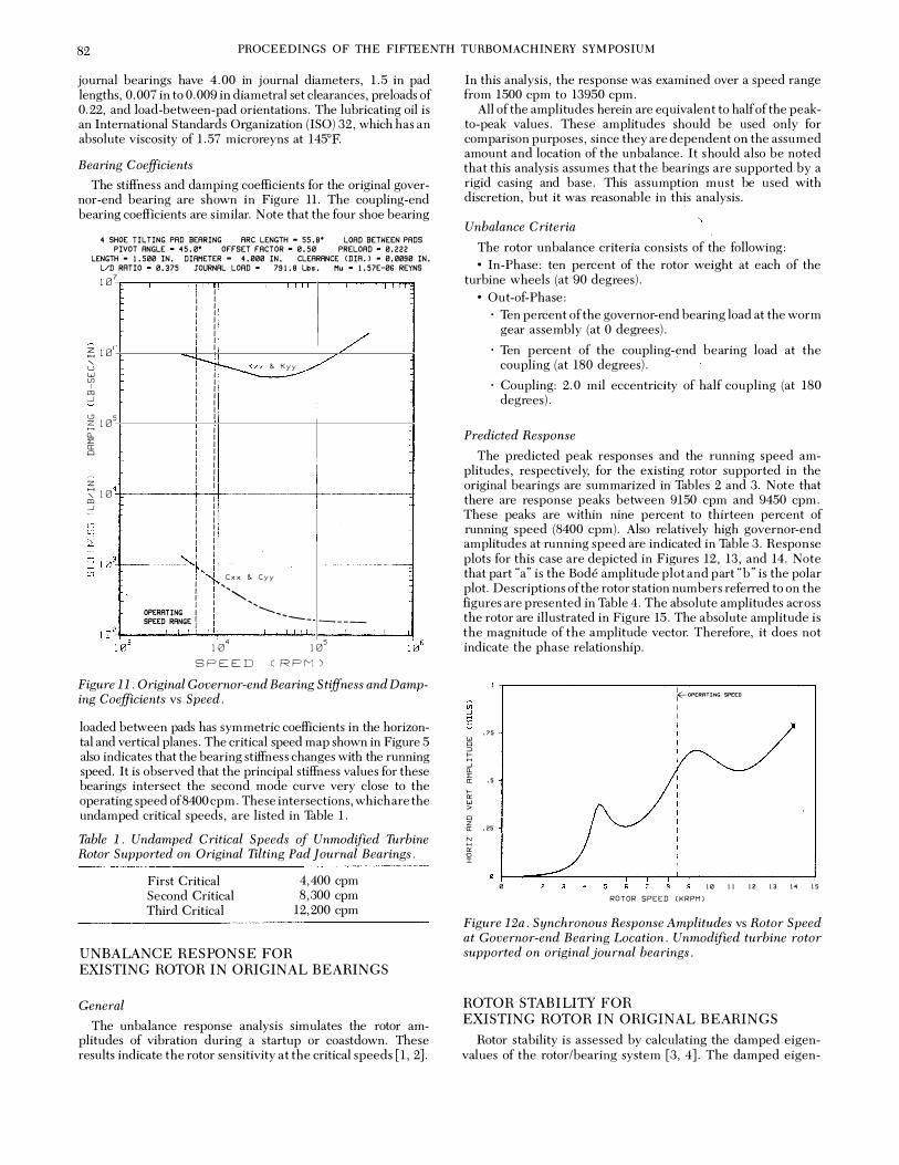
journal bearings have 4. 00 in journal diameters, 1. 5 in pad lengths, 0. 007 in to 0. 009 in diametral set clearances, pre loads of 0. 22, and load-between-pad orientations. The lubricating oil is an International S tandards Organization (ISO) 32, which has an absolute viscosity of 1 . 57 microreyns at l45°F.
Bearing Coefficients
The stiffness and damping coefficients for the original governor-end bearing are shown in Figure 11. The coupling-end bearing coefficients are similar. N ote that the four shoe bearing
4 SHOE TILTING PAD BEARING ARC LENGTH • 55. 8' LOAD BETWEEN PADS
PIVOT ANGLE • 45.8' OFFSET FACTOR • 0.50 PRELOAD • 0.222
LENGTH • 1.500 IN. DIAMETER • 4.000 IN. CLEARANCE CDIA.) • 0.0090 IN.
L/D RATIO • 0.375 JOURNAL LOAD • 791.8 Lbs. Mu • 1.57E-06 REYNS
107
;";10 ' u w (f) I , _j
'-" Z10 H Jl_ :1: cc "'
z '::::10 , _j
6
5
4
I I I I I I I I I I I I I I
/ I I I
'i--f �XX & Kyy __.../ v I I I I I I I I I I I I I I I I I I I I I I I I I I I I I I I I I I I I I I I I I I I I I I
.... ...: I I
l'� Cxx &. Cyy I I ',
, ... I I I I
OPERATING I I ,........, SPEED RANGE I I l
....... __ ... ----
104 105 SPEED CRPM)
Figure 11. Original Governor-end Bearing Stiffness and Damping Coefficients vs Speed.
loaded between pads has symmetric coefficients in the horizontal and vertical planes. The critical speed map shown in Figure 5 also indicates that the bearing stiffness changes with the running speed. It is observed that the principal stiffness values for these bearings intersect the second mode curve very close to the operating speed of 8400 cpm. These intersections, which are the undamped critical speeds, are listed in Table l.
Table 1. Undamped Critical Speeds of Unmodified Turbine Rotor Supported on Original Tilting Pad Journal Bearings.
First Critical Second Critical Third Critical
UNBALANCE RESPONSE FOR
4,400 cpm 8,300 cpm
12,200 cpm
EXISTING ROTOR IN ORIGINAL BEARINGS
General
The unbalance response analysis simulates the rotor amplitudes of vibration during a startup or coastdown. These results indicate the rotor sensitivity at the critical speeds [1, 2].
In this analysis, the response was examined over a speed range from 1500 cpm to 13950 cpm.
All of the amplitudes herein are equivalent to half of the peakto-peak values. These amplitudes should be used only for comparison purposes, since they are dependent on the assumed amount and location of the unbalance. It s hould also be noted that this analysis assumes that the bearings are supported by a rigid casing and base. This assumption must be used with discretion, but it was reasonable in this analysis.
Unbalance Criteria
The rotor unbalance criteria consists of the following: • In-Phase: ten percent of the rotor weight at each of the
turbine wheels (at 90 degrees). • Out-of-Phase:
· Ten percent of the governor-end bearing load at the worm gear assembly (at 0 degrees).
· Ten percent of the coupling-end bearing load at the coupling (at 180 degrees).
· Coupling: 2. 0 mil eccentricity of half coupling (at 180 degrees).
Predicted Response
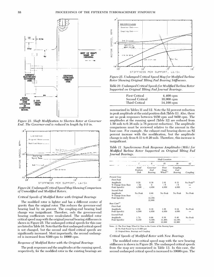
The predicted peak responses and the running speed amplitudes, respectively, for the existing rotor supported in the original bearings are summarized in Tables 2 and 3. N ote that there are response peaks between 9150 cpm and 9450 cpm. These peaks are within nine percent to thirteen percent of running speed (8400 cpm). Also relatively high governor-end amplitudes at running speed are indicated in Table 3. Response plots for this case are depicted in Figures 12, 13, and 14. Note that part "a" is the Bode amplitude plot and part "b" is the polar plot. Descriptions of the rotor station numbers referred to on the figures are presented in Table 4. The absolute amplitudes across the rotor are illustrated in Figure 15. The absolute amplitude is the magnitude of the amplitude vector. Therefore, it does not indicate the phase relationship.
w "' ::> � ;r "
.75
([ .5 .... "' w > "' z a: .25 � "' 0 :I:
0
IE-OPERATING SP££D
I I
1B 11 12 13 14 15 ROTOR SPEED C KRPM)
Figure 12a. Synchronous Response Amplitudes vs Rotor Speed at Governor-end Bearing Location. Unmodified turbine rotor supported on original journal bearings.
ROTOR STABILITY FOR EXISTING ROTOR IN ORIGINAL BEARINGS
Rotor stability is assessed by calculating the damped eigenvalues of the rotor/bearing system [3, 4]. The damped eigen-

DYNAMIC ANALYSIS OF AN 8000 HP STEAM TURBINE OPERATING NEAR ITS SECOND CRITICAL SPEED 83
90
270 HORIZONTAL AMPLITUDE AND VERTICAL AMPLITUDE
FULL SCALE AMPLITUDE = 0.8 MILS AMPLITUDE PER DIVISION = 0.04 MILS
Figure 12b. Nyquist Plot of Response at Governor-end Bearing Location. Unmodified turbine rotor supported on original journal bearings.
�OPERATING SPEED
Iii I .::: I %: I 1.5 I w I "' :l I :::; I -' I .. " I a: I ... I "' w I > I "' I z a: .. I
::: I "' I 0 I :t: I 8
5 6 8 9 IB II 12 13 14 15 ROTOR SPEED CKRPMl
Figure 13a. Synchronous Response Amplitudes vs Rotor Speed at First Stage Wheel Location. Unmodified turbine rotor supported on original journal bearings.
value (s = 'A + iwd) consists of a growth factor ('A) and a damped natural frequency (wd). The growth factor is the rate of exponential decay or growth of the vibration amplitudes.
The logarithmic decrement (3) is used to determine the stability of a system. It is defined as the natural logarithm of the ratio of two successive vibration amplitudes. The logarithmic decrement is computed from the complex eigenvalue by the formula: 3 = - 2'1T'Aiwd. If3 is positive, the system is stable. If3 is negative, the system is unstable. From experience, it is desirable to have a logarithmic decrement greater than or equal to +0.25.
The stability results for the original rotor/bearing system are listed in Table 5. The rotor is stable in the original bearings
90
270 HORIZONTAL AMPLITUDE AND VERTICAL AMPLITUDE
FULL SCALE AMPLITUDE = 2 MILS AMPLITUDE PER DIVISION = 0.10 MILS
Figure 13b. Nyquist Plot of Response at First Stage Wheel Location. Unmodified turbine rotor supported on original journal bearings.
.5 }E-oPCRATlNGi SPEED
Iii I .::: I " .. I I w I "' :l I :::; .3 I -' I .. :0:: I a: I ... I "' .2 w I > I "' I z a: I
::: .l I "' I 0 I :t: I
5 B IB II 1 2 1 3 1 4 15 ROTOR SPEED CKRPMl
Figure 14a. Synchronous Response Amplitudes vs Rotor Speed at Coupling-end Bearing Location. Unmodified turbine rotor supported on original journal bearings.
without external steam cross-coupling effects. The logarithmic decrement is +0.58 at the first forward whirl mode.
SUMMARY OF ORIGINAL SYSTEM DYNAM ICS
This analysis determined that the original rotor/be aring system was operating near the second critical speed. The p redicted second peak response speed range was b etween 9150 cpm and 9450 cpm in the horizontal and vertical planes. The s e peak speeds were within nine percent to thirteen p ercent of the running speed (8400 cpm).
From the predicted response of the original system, it is important to observe the high vibration amplitudes at the

84 PROCEEDINGS OF THE FIFTEENTH TURBOMACHINERY SYMPOSIUM
90
270 HORIZONTAL AMPLITUDE AND VERTICAL AMPLITUDE
FULL SCALE AMPLITUDE � 0.5 MILS AMPLITUDE PER DIVISION = 0.02 MILS
Figure 14b. Nyquist Plot of Response at Coupling-end Bearing Location. Unmodified turbine rotor supported on original journal bearings.
tn .J .... :E: � t. w "' :::J I... .J a. � I ,_ "' � "' � N .... l5 J:
ROTOR STATION NUMBER
Figure 15. Magnitude of Synchronous Response Amplitude Vectors (Magnitude Only) Along Rotor Shaft for Unmodified Turbine Rotor Supported on Original Journal Bearings. Rotor speed is 8400 cpm.
Table 2. Synchronous Peak Response Amplitudes (Mils) for Unmodifwd Turbine Rotor Supported on Original Tilting Pad Journal Bearings.
Shaft Location
11 23 44 Axiol Governor First Coupling
Position End Stage End Disk Bearing Wheel1 Bearing
First Peak Amplitude 0.58 0.38 1.08 0.34 Peak Speed 4,500 4,650 4,650 4,650 Second Peak Amplitude 1.74 0.66 0.37 0.40 Peak Speed(s) 9,150 9,300- 11,400- 12,150-
9,450 12,600 12,900 NOTES: (I) The First Stage Sheel Is Close to the Center of the Bearing Span
(2) No Peak Found Up to 13,950 CPM
47
Coupling
No Peak"
0.69 12,000-12,150
Table 3. Synchronous Response Amplitudes (Mils) at Running Speed ( 8, 400 C PM) for Unmodified Turbine Rotor Supported on Original Ttlting Pad Journal Bearings.
Amplitude (Horizontal & Vertical)
Axiol Position
Disk
1.50
11 Governor
End Bearing
0.56
Shaft Location
23 First Stage
Wheel
0.34
44 Coupling
End Bearing
0.11
47
Coupling
0.29
Table 4. Cross Reference for Unmodified Rotor Computer Model Station Locations.
Station Number
1 11 23
44 47
Location
Axial Position Disk Governor End Bearing First S tage Wheel (Close to Center of Bearing S pan) Coupling-End Bearing Coupling
Table 5. Stability for Unmodified Turbine Rotor Supported on Original Tilting Pad Journal Bearings. Rotor Speed is 8,400 cpm.
Damped Frequency Log Whirl
(CPM) Decrement Condition Direction
4221 +0.58 S table FWD 4204 +0.57 S table BWD
governor-end of the shaft, relative to those at other rotor locations. Thes e amplitudes could cause distress at the governor gears. It is also important that the predicted steam-end bearing amplitudes are higher than those at the exhaust end. This characteristic is opposite to the original field measurements, and it indicates that the governor gear mesh forces are probably significant. However, the characteristic of higher relative amplitudes at the s team end was observed in the balance machine. This is important because in the balance machine the governor worm was not engaged.
Because it is difficult to analytically simulate the true influence of the worm gear, its potential effect was noted but was not included in the rotor model. Instead, the analysis was directed toward identifying the optimum modifications that would move the second critical speed out of the operating speed range. The modifications that were considered included three feasible alteration possibilities:
• Bearing Redesign · This option would consider hydrodynamic stiffnes s and
damping changes to shift the second critical speed or dampen it out. However, care must be taken to avoid increasing the sensitivity at the first critical speed.
• Shaft Modification · A change to the shaft overhangs can have a very signifi
cant effect on the second and third critical speeds. However, shaft changes must be made judiciously because of their irreversibility. Also, there are other mechanical considerations, such as encroachment upon worm gear drives and mechanical overspeed trip pins, which must be considered. This option could also include changes in the bearing span.

DYNAMIC ANALYSIS OF AN 8000 HP STEAM TURBINE OPERATING NEAR ITS SECOND CRITICAL SPEED 85
• Coupling Redesign · This option would consider changes in weight and over
hung moment. Therefore, the coupling change can significantly affect the s econd and third critical speeds. In considering this option, the analyst must ensure that the coupling change does not adversely affect the torsional critical speeds.
NEW TILT PAD J OURNAL BEARING DESIGN
The first modification that was considered in this analysis was a bearing redesign that would fit into the existing bearing brackets without requiring any shaft changes.
Description
The new governor and coupling-end bearings are illustrated in Figure 1 6. The new radial bearings are four-shoe tilt pad bearings with a longer pad length, higher preload and larger pad arc . Specifically, the new design has a length-to-diameter ratio of 1. 0, preload of 0. 33, pad arc of 72 degrees, and orientation of load-between-pad.
Figure 16. New Bearing Design Layout.
Bearing Coefficients
The stiffness and damping coefficients for the new governorend journal bearing are presented in Figure 17. The couplingend coefficients are similar. The critical speed map for the original rotor, showing a cross-plot of the new bearing stiffness values, is shown in Figure 18. Note that the new stiffness still intersects the second critical speed curve in the operating speed range. However, the redesign has improved stiffness and damping characteristics compared to the original design. A comparison of the original and new bearing stiffnesses is also illustrated in Figure 18.
Comparison of Original and New Bearings
The stiffness and damping ratios computed from the formulas presented by Barrett, et al. [5], and discussed by Salamone [6, 7], are listed in Thble 6. Note that for both bearings the stiffness ratios are well below the recommended value of 6. 0 [5]. The important difference is that the new bearings provide more flexibility and more damping than the original bearings. M ost important, the new bearings provide 109 percent of the optimum damping compared to the original 85 percent. Next, the unbalance response and stability calculations will be presented to provide further insight into the merits of one design over the other.
STABILITY AND UNBALANCE RESPONSE WITH NEW BEARINGS
Stability
The original rotor with new bearings has a very s table logarithmic decrement of + 1. 25 (Table 7).
4 SHOE TILTING PAD BEARING ARC LENGTH • 72.0' LOAD BETWEEN PADS
PIVOT ANGLE • 45. 0' OrF"SET FACTOR • 0. 50 PRELOAD • 0. 333
LENGTH • 4.000 IN. DIAMETER • 4.000 IN. CLEARANCE CDIA. l • 0.0105 IN.
VD RATIO • I. 000 JOURNAL LOAD • 791. 8 Lbs. Hu • I. 57E -86 REYNS
107
z H ' tj10 (f) I J:Il -'
'-" z H a.. l: a: 010 z H ' J:Il -'
(f) (f) w c;:10 ..... H 1-(f)
6
5
4
3
"""-..
" ' '
! I I I I I I I I I I I I
�X 8. Kyy � I I I I I I I I
OPERATING
SPEED RANGE
�'�:x 8. Cyy I
I I "'
� I
L /
�" -� -r- ------I
103 SPEED
104 CRPM)
Figure 17. New Governor-end Bearing Stiffness and Damping Coefficients vs Speed.
Governor End--
5: Coup I I ng End··········
�
� 0 1-0 �
5 7 10 10 STIFFNESS PER SUPPORT, Lb/In
Figure 18. Undamped Critical Speed Map for Unmodified Rotor Showing Comparison Between Original and New Tilting Pad ] ournal Bearings.
Unbalance Response
The peak responses and amplitudes at the running s p e ed are listed in Tables 8 and 9. For comparison, these tables also list the base case, which considers the original rotor, bearings and coupling. The percentage changes from the base case give a good indication of improvement with the new bearing design.
The most significant improvement with the new b e arings is the effect on the second critical speed. The second peak responses are damped out with the new bearings (Thbl e 8). In addition, the peak amplitudes at the fir s t critical are reduced by 9 to 43 percent. Significant amplitud e reductions of 3 to 57 percent at the running speed are reflected in Table 9. The rotor center amplitude is increased by six percent, but this increase is

86 PROCEEDINGS OF THE FIFTEENTH TURBOMACHINERY SYMPOSIUM
Table 6. Comparison of Stiffness and Damping Ratios for Original and New journal Bearings. Considers Unmodifzed Rotor.
Bearing Type
Original4 Pad TPJ New4 Pad TPJ
Stiffness Ratio: K(DIM)
Optimum Damping Ratio: topt (DIM)
Actual Damping Ratio: tact (DIM)
1. LID=0.375 2. Preload= 0 .22
2.57
1.79
0.85 48%�opt
1. LID=1.0 2. Preload= 0 .33
1.54
1.27
1.39 109%�opt
Table 7. Stability for Unmodified Turbine Rotor Supported on New Tilting Pad Bearings. Rotor Speed is 8,400 cpm.
Damped Frequency
(CPM)
4552 4532
Log Decrement
+ 1.25 +1.21
Condition
S table S table
Whirl Direction
FWD BWD
Table 8. Synchronous Peak Response Amplitudes (Mils) for Unmodified Turbine Rotor Supported on New Tilting Pad journal Bearings.
Shaft Location
11 23 44 47 Axial Governor First Coupling
Position End Stage End Disk Bearing Wheel (1) Beating Coupling
Present Case First Peak Amplitude 0.53 0.27 0.62 0.20 No Peak2) % Change from Base -9 -29 -43 -41
Peak Speed(s) 4,800 4,950- 5,100- 4,800-
5,550 5,250 4,950
Second Peak Amplitude 2.52 0.57 No Peak No Peak No Peak % Change from Base Peak Speed(s) 12,450- 12,800-
12,900 13,050
Base Cast!-31 First Peak Amplitude 0.58 0.38 1.08 0.34 No Peak Peak Speed(s) 4,500 4,650 4,650 4,650
Second Peak Amplitude 1.74 0.66 0.37 0.40 0.69 Peak Speed(s) 9,150 9,300- 11,400- 12,150- 12,000-
9,450 12,600 12,900 12,150
Notes: (1) The First Stage Wheel Is Close to the Center of the Bearing Span
(2) No Peak Found Up to 13,950 cpm
(3) Original Rotor, Bearings and Coupling
Table 9. Synchronous Response Amplitudes (Mils) at Running Speed (8,400 cpm) for Unmodified Turbine Rotor Supported on New 'lilting Showing New Tilting Pad Bearing Stiffnesses.
Shaft Location
11 23 44 47 Axiol Governor First Coupling
Position End Stage End Disk Bearing Wheel Bearing Coupling
Present Case Amplitude (Horizontal & Vertical) 0.65 0.25 0.36 0.09 0.28
% Change from Base -57 -55 +6 -18 -3
Base CaseOJ Amplitude (Horizontal & Vertical) !.50 0.56 0.34 0.11 0.29
Note: (1) Original Rotor, Bearings and Coupling
from 0.34 to 0.36 and is insignificant. The response amplitude plots and polar plots are presented in Figures 19, 20, and 21. The absolute amplitudes along the rotor at the running speed are illustrated in Figure 22.
f-oPERATING SPE:ED
u; I ;::! I >: I
,75 I w I "' :J I t:; I .J I 11. >: a: .5 I I 1- I "' w I > I
Q I z a: ,25 :::: "' 0 J:
s s 7 e s te 11 12 13 t4 t5
ROTOR SPEED ( KRPM)
Figure 19a. Synchronous Response Amplitudes vs Rotor Speed at Governor-end Bearing Location. Unmodified turbine rotor supported on new journal bearings.
90
270 HORIZONTAL AMPLITUDE AND VERTICAL AMPLITUDE
FULL SCALE AMPLITUDE � 0.6 MILS AMPLITUDE PER DIVISION = 0.04 MILS
Figure 19b. Nyquist Plot of Response at Governor-end Bearing Location. Unmodified turbine rotor supported on new journal bearings.
ROTOR M ODIFICATION
The second level of m odification considered in this analysis is a shaft modification.
Description
The rotor modification (Figure 23) considered cutting off the end of the shaft, just outboard of the thrust collar, and replacing the worm gear governor drive with an electronic governor disk. In this modified-rotor computer model, the governor end of the shaft extends 3.5 in outboard of the thrust disk into the 3.25 in diameter section, where the worm gear was mounted on the

DYNAMIC ANALYSIS OF AN 8000 HP STEAM TURBINE OPERATING NEAR ITS SECOND CRITICAL SPEED 87
.75 w "' :::l � -' "-:t: a: .5 1-"' w > "' z a: .25 N H "' 0 I
�OPERATING SPtED
I I I I I I I I
s 8 9 10 11 12 13 14 15 ROTOR SPEED ( KRPM)
Figure 20a. Synchronous Response Amplitudes vs Rotor Speed at First Stage Wheel Location. Unmodified turbine rotor supported on new journal bearings.
90
270 HORIZONTAL AMPLITUDE AND VERTICAL AMPLITUDE
FULL SCALE AMPLITUDE z 0.8 MILS AMPLITUDE PER DIVISION z 0.05 MILS
Figure 20b. Nyquist Plot of Response at First Stage Wheel Location. Unmodified turbine rotor supported on new journal bearings.
.5
u; ;:{ I: .. w "' :::l
� .3 -' "-I: a: 1-"' .2 w > "' z a: � .I
"' 0 I
f-OPERFITING SPEED
I I
5 6 U� 11 12 13 14 IS ROTOR SPEED ( KRPM)
Figure 2la. Synchronous Response Amplitudes vs Rotor Speed at Coupling-end Bearing Location. Unmodified turbine rotor supported on new journal bearings.
90
0
270 HORIZONTAL AMPLITUDE AND VERTICAL AMPLITUDE
FULL SCALE AMPLITUDE • 0.3 MILS AMPLITUDE PER DIVISION = 0.02 MILS
Figure 21b. Nyquist Plot of Response at Coupling-end Bearing Location. Unmodified turbine rotor supported on new journal bearings.
til ..J H
5 .75 w Cl :::t .,.; ::; .,. . ..J z: a. I: .5 �: ([ �= 1- to � "' w ,_; > a::
Cl z .2 ([ N H "' 0 I
ROTOR STATION NUMBER
Figure 22. Magnitude of Synchronous Response Amplitude Vectors (Magnitude Only) Along Rotor Shaft for Unmodified Turbine Rotor Supported on New journal Bearings. Rotor speed is 8400 cpm.
original shaft. Therefore, on the modified rotor, the amplitudes at the axial position disk refer to the end of this electronic governor disk. The new electronic governor disk was assumed to be a 5. 875 in diameter solid disk with a four-in diameter counterbore that is 0. 188 in deep, as shown in the figure. For reference purposes, this disk would weigh approximately 8. 4 lb. The disk mounting arrangement is shown only for illustration purposes.
Effect on Undamped Critical Speed Map
A comparison of the original and m odified rotor critical speeds is shown in Figure 24. Note the s ignificant increase in the second and third critical speed curves. The map indicates that the shaft modification is very effective in moving the second critical speed.
88 PROCEEDINGS OF THE FIFTEENTH TURBOMACHINERY SYMPOSIUM
---. '- -1 I I r-
__ .J
ELECTIIONIC GOVERNOR
DISXr -o L _J
t 2\S AXIAL
POSmON t r.o&Il§oN � IN COMPUTER
MODEL
EJJSTING OUTBOARD
'l'BJil1ST DISK
REST OF SIL\FI' SAME AS ORIGINAL
Figure 23. Shaft Modification to Shorten Rotor at Governor End. T he Governor-end is reduced in length by 9.0 in.
LEGEND Original Rotor--
Modified Rotor--�---
-Q
w ··�==�������;;�==�����====�;;� 1J: H'l 1 Ul a:: 0 t-o a::
10 5 10 6 STIFFNESS PER SUPPORT, Lb/In
7 10
Figure 24. Undamped Critical Speed Map Showing Comparison of Unmodified and Modified Rotors.
Critical Speeds of Modifzed Rotor with Original Bearings
The modified rotor is lighter and has a different center of gravity than the original rotor. This reduces the governor-end bearing load by six percent. The coupling-end bearing load change was insignificant. Therefore, only the governor-end bearing coefficients were recalculated. The modified rotor critical speed map with the original journal bearing stiffnesses is shown in Figure 25. The undamped critical speeds for this case are listed in Table 10. Note that the first undamped critical speed is not changed, but the second and third critical speeds are significantly increased. Most importantly, the second undamped is increased from 8300 cpm to 10000 cpm.
Response of Modified Rotor with the Original Bearings
The peak responses and the amplitudes at the running speed, respectively, for the modified rotor in the existing bearings are
BEARINGS Governor End--
� Coupling End-------
0:: -
Q W
4 3rd Critical
:r 10 Ul a:: 0 f--0 a::
' 10 �--�������.--�������������, 10 10
STIFFNESS PER SUPPORT, Lb/In
Figure 25. Undamped Critical Speed Map for Modified Turbine Rotor Showing Original Tilting Pad Bearing Stiffnesses.
Table 10. Undamped Critical Speeds for M odified Turbine Rotor Supported on Original Tilting Pad ] ournal Bearings.
First Critical S econd Critical Third Critical
4,400 cpm 10,000 cpm 14,100 cpm
summarized in Tables 11 and 12. N ote the 52 percent reduction in peak amplitude at the axial position disk (Thble 11). Also, there are no peak responses between 9150 cpm and 9450 cpm. The amplitudes at the running speed (Thble 12) are reduced from 1.50 mils to 0.36 mils (a 76 percent reduction). The amplitude comparisons must be reviewed relative to the amount in the base case. For example, the exhaust end bearing shows an 82 percent increase with the modification, but the amplitude change is only from 0.11 to 0.20 mils. Therefore, this increase is insignificant.
Table 11. Synchronous Peak Response Amplitudes (Mils) for Modified Turbine Rotor Supported on Original Tilting Pad journal Bearings.
Shaft Location
6 18 39 Axial Governor First Coupling
Position End Stage Disk Bearing Wheel(l!
Present Case First Peak Amplitude 0.28 0.38 1.01 % Change from Base -52 0 -6
Peak Speed(s) 4,500 4,650 4,650
Second Peak Amplitude No Peak 0.68 No Peak % Change from Base Peak Speed(s) 12,150-
12,600
Base c .. <fJJ First Peak Amplitude 0.58 0.38 1.08
Peak Speed(s) 4,500 4,650 4,650
Second Peak Amplitude 1.74 0.66 0.38
Peak Speed(s) 9,150 9,300- 11,400-
9,450 12,600
Notes: (1) The First Stage Wheel Is Close to the Center of the Bearing Span
(2) No Peak Found Up to 13,950 cpm
(3} Original Rotor, Bearings and Coupling
End Bearing
0.31 -9
4,650
No Peak
0.34
4,650
0.40
12,150-
12,900
Critical Speeds of Modified Rotor with New Bearings
42
Coupling
No Peak(')
No Peak
No Peak
No Peak
The modified rotor critical speed map with the new bearing s tiffnesses is shown in Figure 26. The undamped critical speeds from the map are summarized in Table 13. In this case, the second undamped critical speed is increased to 10600 cpm. The

DYNAMIC ANALYSIS OF AN 8000 HP STEAM TURBINE OPERATING NEAR ITS SECOND CRITICAL SPEED 89
Table 12. Synchronous Response Amplitudes (Mils) at Running Speed (8,400 cpm) for Modified Turbine Rotor Supported on Original Tilting Pad J oumal Bearings.
-�--------------------
Shaft Location
lR 39 42 Axial Goccnwr Firsi Coupling
Position End Stage End Disk Bearing Whal Bearing Coupling
Pn:,,·ent Case Amplitude (Horizoutal & Vertical) O.:JG 0.:37 0.34 0.20 0.38
% Chang-e from Base -';'(i --:34 () +�2 -t-31
Base Ca.'iC:I,' '\.mptitude (l{orizontal & Vertical) J.,'j() 0.56 0.3-! 0, ll 0.29
;'\lote: (1) Origiual Rotor, lkarili),!;S aud Cnupling
mode shapes of the modified rotor supported in the new hearings arc illustrated in Figures 27 and 28. Notice that this second
. mode shape shows more coupling-end bearing am
plitude than the original second mode shape. This additional motion provides better utilization of the fluid film damping in the hearings. This point is further confirmed by comparing the stifli1Css and damping ratios, previously rliscussed. A comparison of the original and new bearings with the rnodit1ed rotor is presented in �Htble 14. Note that the actual damping ratio increases from 47 percent to 110 percent of the optimum.
L. [I CJ::'
Cl
Coup I .ng lnd-----
i�� l [I ·1 j___:.�'_'::.;_;,�.:_---+----[L IJj
112
fipc:�d i<<J.r,qe - ""--�----------
'
•c; r 1 1 k1
I�
j 'VJG
I , l ___ h .. 'In
Figure 26. Undamped Critical Speed Map j(!r Modified Turbine Rotor Showing New Tilting Pad Bearing Stif.fnesses,
18
�10DE 1 FREQUENCY 3,697.3 CPM
20 30 40 RXIRL LENGTH,
50 60 Inches
78 80
Figure 27. Mode Shape at First Undamped Critical Speed (3697 CPI\1) for Modified Rotor Supported on New Bearings (Kb 4.7 x 10⁵ LB!IN).
MODE FREQUENCY 10,603.2 CPM
10 ?0 31B 50 6'0 AXIAL LENGTH, Inches
70
Figure 28. Mode Shape at Second Undamped Critical Speed (10609 CPM) for Modified Rotor Supported on New Bearings (Kb = 7.50 x 10⁵ LBIIN).
Tahle 13. Undamped Critical Speeds{ur Modified 1l.1rhine Rotor Supported on New Tilting Pad Journal Bearings.
First Critical Second Critical Third Critical
3,700 cpm 1 0,600 cprn 1 6,:300 cpm
Table 14. Comparison of Stiffness and Damping Hatios for Original and New.foHmal Bearings. Considers Modified Hotor.
Original;/ Pad Tl�f
Stiffness Hatio: f.: (DlM)
Optimum Damping Hatio: <opt (DIM)
Actual Damping Hatio: <act (DIM) .
1. UD=0.375 2. Preload= 0.22
2.48
l.74
0 83 47%�c>pt
Stability and Response of Modified Rotor with Odginal Bearings
Nerc 4 Pad TP] 1. ])/) = z .0 2. Preload=0 . .3:3
1.51
1.26
].38 ll()o/c�opt
The modified rotor with new bearings has a very stable logarithmic decrement of + L'30 (Table L'5).
Table 15. Stab'ility fur Modified Tit rhine Hotor Supported on New Tilting Pad Bearings. Rotor Speed is 8,400 cpm.
Damped Frequency Log Whirl
(CPM) Decrement Condition Direction
4512 + 1.30 Stable FWD 4492 +1.26 Stable BWD
The peak responses and amplitudes at the running speed, including comparisons to the base case, as previously discussed, are listed in Tables 16 and 17. The rotor modification shows a very significant improvement in amplitudes at the firs t critical speed ('TI1ble 1 6). There are amplitud e reductions between 1 8 percent and 3 3 percent at all locations. Finally, s ignificant running speed amplitude reductions of 64 percent at the

90 PROCEEDINGS OF THE FIFTEENTH TURBOMACHINERY SYMPOSIUM
governor-end bearing and 94 percent at the new governor/ position disk are shown in Thble 17. The amplitude increases are not out of proportion relative to the rest of the rotor. The response amplitudes at the running speed and the response plots are presented in Figures 29, 30 and 31. The absolute amplitude distribution across the rotor at the running speed is illustrated in Figure 32. The descriptions of each modified rotor station number are presented in Table 18.
Table 16. Synchronous Peak Response Amplitudes (Mils) for Modified Turbine Rotor Supported on New Tilting Pad Journal Bearings.
Shaft Location
6 18 39 Axial Governor First Coupling
Present Case First Peak Amplitude % Change from Base Peak Speed(s)
Second Peak Amplitude % Change from Base Peak Speed(s)
Base Casel3! First Peak Amplitude Peak Speed(s)
Second Peak Amplitude Peak Speed(s)
Position Disk
0.32
-45
4,800-
5,100
No Peak
0.58
4,500
1.74
9,150
End Stage Bearing Wheel (1)
0.27 0.60
-29 -44
5,100- 5,100
5,400 5,250
No Peak No Peak
0.38 1.08
4,650 4,650
0.66 0.37
9,300- 11,400-
9,450 12,600
Notes: (1) The First Stage Wheelis Close to the CentPr of tlw Bearing Span
(2) No Peak Found Up to 13,950 cpm
(3) Original Rotor, Bearings and Coupling
End Bearing
0.18
-47
4,650-
4,950
No Peak
0.34
4,650
0.40
12,150-
12,900
42
Coupling
No Peak21
No Peak
No Peak
0.69
12,000-
12,150
Table 17. Synchronous Response Amplitudes (Mils) at Running Speed (8,400 cpm) for Modified Turbine Rotor Supported on New Tilting Pad Journal Bearings.
Shaft Location
6 18 39 42 Axial Governor First Coupling
Position End Stage End Disk Bearing Wheel Bearing Coupling
Present Case Amplitude O.Q7 0.19 0.38 0.13 0.32
(Horizontal & Vertical) % Change from Base -95 -66 +12 +18 +lO
Base Casin Amplitude 1.5 0.56 0.34 0.11 0.29
Note: (1) Original Rotor, Bearings and Coupling
Table 18. Cross Reference for Modified Rotor Computer Model Station Locations.
Station Number
1
6 18
39 42
Location
Axial Position/Electronic Governor Disk
Governor-End Bearing First S tage Wheel
(Close to Center of Bearing Span) Coupling-End Bearing Coupling
ALTERNATE COUPLING DESIGN An alternate coupling design was evaluated, because there
was concern about coupling gear tooth lockup in the original design. The alternate design is a dry-type coupling. This design
.5 �OPERATING SPEED "' ;::: :E . . w "' :::J 1-H .3 ...J a. :E a: 1-"' .2 w > "' z a: ::: . I "' 0 I
11;3 11 12 13 14 15
ROTOR SPEED ( KRPM)
Figure 29a. Synchronous Response Amplitudes vs Rotor Speed at Governor-end Bearing Location. Modified turbine rotor supported on new journal bearings.
90
180 0
270 HORIZ AND VERTICAL AMPLITUDE
FULL SCALE AMPLITUDE = 0.3 MILS AMPLITUDE PER DIVISION = 0.02 MILS
Figure 29b. Nyquist Plot of Response at Governor-end Bearing Location. Modified turbine rotor supported on new journal bearings.
drives through a multiple element, laminated disk-pack instead of gear teeth. The half-coupling weight of the alternate is 36. 5 lb (not including the integral shaft flange) .
In this analysis, the alternate coupling design yielded rotor vibration characteristics that were very similar to those obtained with the original gear coupling. Therefore, the justification for changing couplings would be that the dry coupling would not be susceptible to drive lockup and unbalance eccentricity due to tooth wear.
SUMMARY AND CONCLUSIONS A case history of an 8000 hp steam turbine vibration problem
and solution was presented. The field vibration data obtained from this unit indicated that it was operating near a critical speed. This characteristic caused ramping vibration levels at the bearings as the unit was brought up to its operating speed of 8400 cpm. Synchronous bearing vibration levels of 3. 0 mils to

DYNAMIC ANALYSIS OF AN 8000 HP STEAM TURBINE O PERATIN G NEAR ITS SECOND CRITICAL SPEED 9 1
IE-OPERATING SPEED
I I I
. 75 w "' :;:J 1-� _j I)_ >::
. s 0:
1-0: w > "' z 0: . 25
� 0: 0 J:
10 1 1 12 13 14 1 5 ROTOR SPEED ( KRPM J
Figure 30a. Synchronous Response Amplitudes vs Rotor Speed at First Stage Wheel Location. Modified turbine rotor supported on new journal bearings.
90
270 HORI Z AND VERT I CAL AMPLI TUDE
FULL SCALE AMPLITUDE = 0.8 MILS AMPLITUDE PER DIVISION = 0.05 MILS
Figure 30b. Nyquist Plot of Response at First Stage Wheel Location. Modified turbine rotor supported on new journal bearings.
4. 0 mils were recorded. These symptoms caused concern for long-term reliability of this critical piece of turbomachinery, because continuous operation at these high vibration levels could significantly shorten bearing life and, potentially, rotor integrity. A rotordynamics computer simulation of the rotor/ bearing system predicted that the second peak response speed range was between 9150 cpm and 9450 cpm in the horizontal and vertical planes. These peaks were within nine percent to thirteen percent of running speed.
Once the simulation identified the problem, it was necessary to determine where the most effective changes could be made in order to eliminate, or at least minimize, this critical speed sensitivity. It should be clarified that the feasible region for solutions is tightly bound, due to cost considerations. Therefore, the number of possible changes is limited. Three alteration possibilities were considered in this analysis :
• Bearing Redesign
.5 j.E-OPERATING SP££D
;;; I ;::! I >: . . I
I w I "' :;:J I 1-� . . _j I)_ I: 0:
1-0:
. 2 w > "' z 0: � . l 0: 0 J:
1 0 1 1 1 2 1 3 1 4 1 5 ROTOR SPEED ( KRPM J
Figure 31a. Synchronous Response Amplitudes vs Rotor S peed at Coupling-end Bearing Location. Modified turbine rotor supported on new journal bearings.
90
270 HORI Z AND VERT I CAL AMPL I TUDE
FULL SCALE AMPLITUDE = 0.3 MIL S AMPLITUDE PER DIVISION = 0.02 MIL S
Figure 31b. Nyquist Plot of Response at Coupling-end Bearing Location . Modified turbine supported on new journal bearings.
• Shaft Modification • Coupling Redesign For this machine, the optimum feasible solution was to
shorten the shaft at the governor end and replace the bearings . The shaft modification consists o f cutting off the governor worm gear assembly and replacing it with an electronic governor disk. This new bearing design is also a four-shoe tilting pad journal bearing, but it has longer pads and higher preload than the existing design. This bearing has a length-to-diameter ratio of 1.0, preload of 0 . 33, and orientation of load-between-pads. It should be noted that the bearing change improves the v ibration characteristics even if the rotor is not modified. However, this choice would be a compromise , because the shaft modification makes an even more significant improvement.
B ecause there was concern about coupling gear tooth lockup in the original design, an alternate coupling design was evaluated. A coupling change was also of interest , because of its

92 PROCEEDINGS OF THE FIFTEENTH TURBO MACHINERY SYMPOSIUM
u; . 5
.J H :E w "' . 4 ::J ... H .J a. :0:: a: . . ... "' w > "' . 2 z a:
::::: "' 0 . I I w ... ::J .J � � 0 9 <n "' a:
4 1
Figure 32. Magnitude of Synchronous Response Amplitude Vectors (Magnitude Only) Along Rotor Shaft for Modified Turbine Rotor Supported on New journal Bearings. Rotor speed is 8400 cpm.
Figure 33. Lower Half of Governor-end (Outboard) Radial Journal Bearing After One Year of Service.
Figure 34. Lower Half of Coupling-end (Inboard) Radial ] ournal Bearing After One Year of Service.
potential effect on moving the second critical speed. The alternate design is a dry coupling which drives through a multiple element, laminated disk-pack instead of gear teeth. In this analysis , it was determined that the rotor response characteristics were very close with either the existing gear coupling or the dry coupling. Therefore , the justification for changing couplings was that the dry coupling would not be susceptible to
drive tooth lock-up and unbalance eccentricity due to tooth wear.
It should be clarified that the physical solution was approached in two phases . In this case , a significant improvement could be achieved with the bearing change . Therefore , the new bearings were installed on the first shutdown. This change alone reduced field vibration readings by approximately 50 percent . The rotor modification is more involved b ec ause of considerations previously discussed. However, an implementation plan is in progress because the rotor simulation indicates even further improvement.
One of the most important points to be e mphasized herein was that the analytical study identified degre e s of improvement without requiring experimentation on the actual machine . Therefore, the rotor modification was separated into a second phase that could be investigated while the rotor was up and running at full production rates .
A s o f this writing, the m achine has been running for over one year with the new bearing design and the dry coupling. The vibration levels have been well controlled and there have been no production interruptions . Bearing photographs taken during a recent routine unit turnaround are presented in Figures 33 and 34 . The scoring marks in the babbitt were made by dirt particles in the oil. However, the bearings were found to be in good general condition after this length of service . In fact , these bearings were reinstalled without changing the pads and are back in operation .
REFERENCES
1 . Lund, J. W , and Orcutt, F. K. , "Calculations and Experiments on the Unbalance Response of a Flexible Rotor, " Journal of Engineering for Industry, 'fransactions of AS M E (November 1967) .
2. Salamone, D . J . , and Gunter, E . J . , "Effects of Shaft Warp and Disk Skew on the S ynchronous Unbalance Response of a Multimass Flexible Rotor in Fluid Film Bearings , " Topics in Fluid Film Bearing and Rotor Bearing System Design and Optimization, AS M E Book N o . 100118 ( 1978) .
3. Gunter, E . J . , "Dynamic S tability of Rotor-Bearing Systems , " NASA S P- 113 ( 1 966) .
4. Lund, J . W , " Stability and Damped Critical Speeds of a Flexible Rotor in Fluid Film Bearings , " Journal of Engineering for Industry, 'fransactions of ASM E , pp. 509-51 7 (May 1974) .
5. Barrett, L. E . , Gunter, E . J . , and Allaire , P. E . , " Optimum Bearing and Support Damping for Unbalance Response and S tability of Rotating M achinery, " Journal of E ngineering for Power, 'fransactions of A S M E , 100 ( 1 ) , pp . 89-94 (1978) .
6. Salamone, D . J . , "Journal Bearing Design Types and Their Applications to Turbomachinery, " Proceedings of the T hirteenth Turbomachinery Symposium, Turbomachinery Laboratories, Texas A&M University, College S tation, Texas , pp. 179- 188 (1984) .
7. Salamone, D . J . , "Introduction to Hydrodynamic Journal B e ar i n g s , " Vibration Institute Minicourse NotesMachinery Vibration Monitoring and Analysis, Clarendon Hills , Illinois : The Vibration Institute, pp . 4 1 -56 ( 1985) .
ACKNOWLEDGEM ENT
Special thanks to M r. M alcolm Leader, Assistant Chief Engineer, S alamone Turbo E ngineering, Incorporated, for his valuable assistance in the preparation of the art work used in this paper.