by jim anderson, ph.d., and david gustafson, p.e. a
TRANSCRIPT

As alternative onsite systems prolif-erate, as emphasis on manage-ment grows, more systems are
using timers. Timers allow onsite systems to operate
over a wider range of sites and conditions.The timer control panel allows the opera-tion of a pump based on common timeinstead of on-demand use. This allows dis-persion of flow over the entire day,smoothing out peak flows that occur dur-ing the early morning and evening andreducing stress on the system.
Timed dosing helps the system oper-ate more effectively and maximize treat-ment efficiency. Some technologies, likerecirculating filters, require a timer
because they are designed to be loadedindependent of daily use patterns.
Many optionsThere are many makes and models of
timers, but essentially there are two kinds:clocks and programmable logic controllers(PLCs). Clocks simply track time, and ifyou use them you will need two – one forthe on function and one for the off func-tion.
A PLC is actually a small computerand as such allows more flexibility. It givesmore potential settings and makes it easierto capture data you can use to assess andmanage the system. PLCs appear to bevery stable and work in a wide range of sit-uations.
When using a timer to accommodatethe storage of surge flows generated by atypical home, the size of the pump tankshould be about twice the daily flow. Thisallows for peak use to be evenly dosedthrough the day.
If you use a timer in a commercial set-ting, then the tank should be large enoughto store any extended peaks that are ofconcern. This allows the soil treatment ordispersal area to be designed for less thanpeak flows, minimizing size and cost.
Choosing the settingsTo be most effective, the timer should
be set to deliver doses to the system thattotal 50 to 60 percent of the daily designflow. This level usually closely approxi-mates actual water usage. The installation
must include an alarm triggered by flowsabove the preset level. If the setting is notadequate, the timer can be reset.
On the other hand, when the systemis on a site that limits the size of the dis-persal area, the timer will be set at thedesign flow. In this case, the alarm identi-fies when the flows exceed the designvalue. Any such instance is significant, andrepeated events will require the owner totake management steps to reduce the flow.
When setting a timer, the installer setstwo specific times. The first is the timethat the pump will operate to deliver thedesired dose volume. The second is thepump off cycle. Timing is based on thenumber of times the pump will operateduring the day.
The dose volume is based on three
conditions: • The total amount of effluent to
be delivered to the system.• The drain-back amount in the
piping from the system to the tank.• The desired dose volume.
The maximum dose volume should beno greater than a quarter of the daily flow.For example, if the design flow is 600 gpd,the maximum dose would be 150 gallons.
The minimum dose would be enougheffluent to charge the distribution systemfour times. For example, if the distributionsystem consists of 1.5-inch pipes (0.11gallons per foot of pipe) and there is 100feet of pipe, the volume to charge wouldbe 11 gallons. Four times the charge vol-ume would total 44 gallons.
Four times the charge volume is nec-
Right On Time
basictraining
Proper timer settings help ensure that onsite systemsdeliver reliable treatment and function at optimum efficiencyBy Jim Anderson, Ph.D., and David Gustafson, P.E.
Jim Anderson and David Gustafson are with theUniversity of Minnesota’s widely recognized onsitewastewater treatment education program. Jim isDirector of the university’s Water Resources Center,and Dave is the university’s Extension Onsite SewageTreatment Educator. Readers are welcome to submitquestions or article suggestions to Jim and Dave. Writeto [email protected].
[ ]
A less sophisticated timer for a dual pump system.A less sophisticated timer for a dual pump system.
A recirculating filter controlled by a timer.
A recirculating filter controled by a timer.
essary to operate the system because thefirst 11 gallons would simply fill the pip-ing, and the last 11 gallons would gravityflow back out of the pipe after the pumpshut down. The 22 gallons in between isthe dose that is physically sprayed out ofthe pressure laterals.
For illustrationTo understand this, consider an exam-
ple. If the design flow for a system is 600gpd, then the timer should be set to deliv-er a total of 300 to 400 gallons during theday. If we choose the 50 percent figure(300 gpd), and if the timer will turn on sixtimes, the dose volume would be 50 gal-lons. This is greater than the minimum(44 gallons), but not a lot more – so sixwould be the maximum number of timesfor the pump to turn on.
If the timer is set to dose 50 gallons,the drainfield does not actually get a doseof 50 gallons because the water in the dis-tribution pipe will drain back. If a checkvalve is used to prevent drain-back, then50 gallons would be the proper setting,but for cold-weather applications it is nec-essary to allow the pipe to drain back.
The volume of the drain-back from thesupply pipe is calculated by multiplyingthe length of pipe by the volume per foot.If 2-inch PVC pipe is used for this line and
the distance is 100 feet, then the volumeof drain-back in that pipe is 100 feet times0.17 gallons per foot, or 17 gallons. Thetotal dose volume then would be 50 gal-lons for the system, plus 17 gallons for thedrain-back, or 67 gallons per dose.
Pump performanceThe next step is to determine the
amount of water the pump actually deliv-ers. Some installers and designers like todo this at their desk. Each system andeach pump is different, so the only way toknow is to field test. First, a field testrequires knowledge of the tank volume.Let’s assume the tank has a volume of 30gallons per inch.
Next, we calculate the flow rate in gal-lons per minute delivered by the pump. Todo this, we measure the level of the efflu-ent in the tank, measuring down from thetop of the riser to the surface of the water.Let’s assume the level is 60 inches. Now,we turn the pump on and measure thetime. Suppose we run the pump for twominutes, and the effluent level drops to 63inches from the top of the riser.
This means the liquid in the tank wentdown three inches in two minutes. If thetank holds 30 gallons per inch, and thelevel dropped three inches, the volumepumped is 90 gallons. Since the pump
delivered 90 gallons in two minutes, thepump capacity in this system is 45 gpm.
If the timer system is to deliver 67 gal-lons per dose to the soil system, we nexthave to calculate how long the pumpneeds to run. To do this, we divide thedose volume by the pump capacity. In ourexample, 67 gallons divided by 45 gpmyields about 1.5 minutes.
Resting timeThe next piece is setting the time off,
or resting time, for the system. There are1,440 minutes in a day. Since we said wewould like the pump to turn on six times,1,440 minutes divided by six doses worksout to 240 minutes. To be more exact, wecan subtract the 1.5 minutes during whichthe pump is on (delivering a dose) and setthe off timer for 240 minutes minus 1.5minutes, or 238.5 minutes. The timer isnow set.
The floats inside the tank still need tobe properly installed. There will be two orthree floats in the tank. With a simple
clock timer, there are two floats: the offfloat and the alarm float. The off floatshould be set right above the pump tokeep it submerged. The second float is thealarm float. This float should never operatethe pump – it should only be used for thealarm.
For more sophisticated PLC timers,we can use a peakable float. This float istypically set up at 50 percent of the tankvolume, and the alarm float is set three tofour inches above it.
This peakable float can change theflow to the system based on the flowpeaks. For our example, it could changethe resting time from 240 minutes to 120minutes. This would mean the systemnow receives 600 gpd, or the design flow.
With this control option, the systemcan adjust to peak flows without trippingan alarm. If this happens with regularity,system efficiency and performance willsuffer. Therefore, this method requiresmore frequent monitoring so the timer canbe changed if necessary. ■
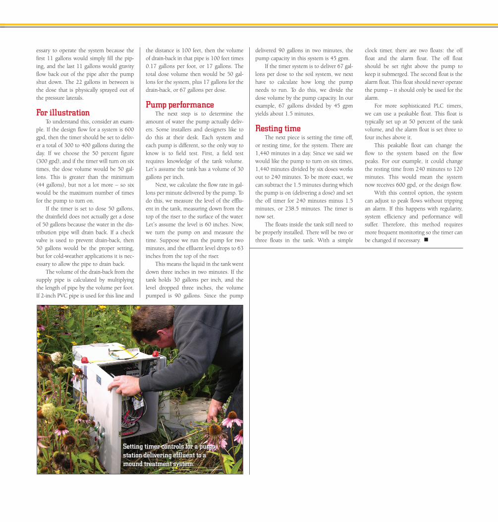
Setting timer controls for a pumpstation delivering effluent to amound treatment system.
Setting timer controls for a pumpstation delivering effluent to amound treatment system.