by order of the air force instruction 11-2f-16,...
TRANSCRIPT

BY ORDER OF THE SECRETARY OF THE AIR FORCE
AIR FORCE INSTRUCTION 11-2F-16, VOLUME 3
18 FEBRUARY 2010
Flying Operations
F-16--OPERATIONS PROCEDURES
COMPLIANCE WITH THIS PUBLICATION IS MANDATORY
ACCESSIBILITY: Publications and forms are available on the e-Publishing website at
www.e-publishing.af.mil for downloading or ordering.
RELEASABILITY: There are no releasability restrictions on this publication.
OPR: HQ ACC/A3TO
Supersedes: AFI11-2F-16V3, 30
September 2005
Certified by: HQ USAF/A3O-A
(Mr. Gerald F. Pease, Jr., SES)
Pages: 67
This publication establishes effective and safe operations of the F-16 and implements AFPD 11-
2, Aircraft Rules and Procedures; AFPD 11-4, Aviation Service; and AFI 11-202V3, General
Flight Rules. It establishes the minimum Air Force operations procedures for personnel
performing duties in the F-16. This publication applies to the US Air Force Reserve Command
(AFRC) and the Air National Guard (ANG). MAJCOMs, Direct Reporting Units (DRU) and
Field Operating Agencies (FOA) will forward proposed MAJCOM/DRU/FOA-level
supplements to this volume to HQ USAF/A3O-AT, through HQ ACC/A3TO, for approval prior
to publication IAW AFPD 11-2, paragraph 4.2 Copies of approved and published supplements
will be provided by the issuing office to HQ USAF/A3O-AT, HQ ACC/A3TO, and the user
MAJCOM/ DRU/FOA offices of primary responsibility (OPR). Field units below
MAJCOM/DRU/FOA level will forward copies of their supplements of this publication to their
parent MAJCOM/DRU/FOA OPR for post-publication review. NOTE: The above applies only
to those DRUs/FOAs that report directly to HQ USAF. Keep supplements current by complying
with AFI 33-360, Publications and Forms Management.
Waiver authority to this publication is established in paragraph 1.3 See paragraph 1.4 for
guidance on submitting comments and suggesting improvements.
This instruction requires the collection or maintenance of information protected by the Privacy
Act of 1974. The authority to collect and maintain the records prescribed in this instruction are
37 USC 301a, Incentive Pay; Public Law 92-204 (Appropriations Act for 1973), Section 715;
Public Law 93-570 (Appropriations Act for 1974); Public Law 93-294 (Aviation Career
Incentive Act of 1974); DOD Instruction 7730.57, Aviation Career Incentive Act of 1974 and
Required Annual Report; AFI 11-401, Aviation Management; and E.O. 9397, Numbering System
Certified Current, 25 APRIL 2012

2 AFI11-2F-16V3 18 FEBRUARY 2010
for Federal Accounts Relating to Individual Persons. System of records notice F011 AF/XOA,
Aviation Resource Management System (ARMS), applies.
Records Disposition. Ensure that all records created as a result of processes prescribed in this
publication are maintained in accordance with AFMAN 33-363, Management of Records, and
disposed of in accordance with the Air Force Records Disposition Schedule (RDS) located under
AFRIMS in the Air Force Portal A-Z Applications List.
NOTE:
This instruction contains references to the following field (subordinate level) publications and
forms which, until converted to departmental level publications and forms may be obtained from
the respective MAJCOM publication distribution office.
SUMMARY OF CHANGES
This document has been substantially revised and must be completely reviewed. Major changes
include: changes waiver authority for those forces presented to a COMAFFOR; brings minimum
safe altitude/route abort altitude computations into compliance with AFI 11-202V3; complies
with HQ USAF direction to capture Chemical, Biological, Nuclear and High-Yield Explosive
(CBRNE) information from rescinded AFI 10-2602 by creating a new Attachment 2; complies
with HQ USAF direction to add language about aviation fuel optimization culture; adds guidance
for GCAS settings; makes numerous administrative changes; increases standardization with other
Combat Air Forces (CAF) 11-2MDS Volume 3s.
Chapter 1—GENERAL GUIDANCE 7
1.1. Abbreviations, Acronyms, and Terms. .................................................................. 7
1.2. Responsibilities. ..................................................................................................... 7
1.3. Waivers. ................................................................................................................. 7
1.4. Processing Changes. .............................................................................................. 7
Chapter 2—MISSION PLANNING 8
Section 2A—-General 8
2.1. Responsibilities. ..................................................................................................... 8
2.2. Bird/Wildlife Aircraft Strike Hazard (BASH) Programs. ...................................... 8
2.3. Standards. ............................................................................................................... 8
2.4. CBRNE. ................................................................................................................. 8
2.5. Flight Material Preparation. ................................................................................... 8
2.6. Fuel Conservation. ................................................................................................. 9
2.7. Overwater. .............................................................................................................. 9
2.8. Briefing and Debriefing. ........................................................................................ 9

AFI11-2F-16V3 18 FEBRUARY 2010 3
2.9. Unit Developed Checklists/Local Pilot Aids. ........................................................ 11
Section 2B—Night (see also night sections of Chapter 3, Chapter 5 and Chapter 6) 11
2.10. Minimum Safe Altitude (MSA). ............................................................................ 11
2.11. Night chart requirements. ....................................................................................... 11
2.12. Low Altitude Navigation and Targeting Infra Red for Night (LANTIRN) Navigation Pod
Operations. ............................................................................................................. 11
Chapter 3—NORMAL OPERATING PROCEDURES 13
Section 3A—Ground Operations 13
3.1. Preflight. ................................................................................................................ 13
3.2. Ground Visual Signals. .......................................................................................... 13
3.3. Taxi and Arming. ................................................................................................... 14
3.4. EOR Inspections and Before Takeoff Checks. ...................................................... 14
3.5. Flight Lineup. ......................................................................................................... 15
Section 3B—Takeoff and Departure 15
3.6. Takeoff. .................................................................................................................. 15
3.7. Initial Join-up and Rejoins. .................................................................................... 16
Section 3C—-Enroute 16
3.8. Air Refueling. ........................................................................................................ 16
3.9. Aircraft Handling Characteristics (AHC)/Maneuvering Parameters. .................... 16
3.10. Formation, General. ............................................................................................... 17
3.11. G-Awareness Exercises (G-Ex) (Reference AFTTP 3-3. ...................................... 17
3.12. Tactical Formations. .............................................................................................. 18
3.13. Chase Formation. ................................................................................................... 19
3.14. Show Formation. .................................................................................................... 19
3.15. Low Altitude Operations (reference AFTTP 3-1. .................................................. 19
Section 3D—-Recovery and Landing 21
3.16. Gear Checks. .......................................................................................................... 21
3.17. Angle of Attack (AOA). ........................................................................................ 21
3.18. Landing restrictions. .............................................................................................. 21
3.19. Desired touchdown point and spacing. .................................................................. 21
3.20. Low Approaches. ................................................................................................... 21
3.21. Touch-and-Go Landings. ....................................................................................... 22

4 AFI11-2F-16V3 18 FEBRUARY 2010
3.22. Overhead Traffic Patterns. ..................................................................................... 22
3.23. Tactical Overhead Traffic Patterns. ....................................................................... 22
3.24. Closed Traffic Patterns. ......................................................................................... 22
3.25. Back Seat Approaches and Landings. .................................................................... 22
3.26. Formation Approaches and Landings. ................................................................... 22
Section 3E—Night (see also night sections of Chapter 2, Chapter 5 and Chapter 6) 23
3.27. General Night Procedures. ..................................................................................... 23
3.28. Operating with both Night Vision Goggles (NVG) and Terrain Following Radar (TFR). 23
3.29. Night Vision Goggles (NVG) Procedures. ............................................................ 24
3.30. Terrain Following Radar (TFR) Operations at Night. ........................................... 24
Section 3F—Other 25
3.31. Targeting Pod Operations. ..................................................................................... 25
3.32. Radio Procedures. .................................................................................................. 25
3.33. Lap Belts. ............................................................................................................... 26
3.34. Change of Aircraft Control. ................................................................................... 26
3.35. Fuel Requirements. ................................................................................................ 26
3.36. Radar Altimeters and Terrain Warning/Avoidance Systems. ................................ 26
3.37. Wind and Sea State Restrictions. ........................................................................... 27
3.38. Identification Friend or Foe/Selective Identification Feature (IFF/SIF). ............... 27
Chapter 4—INSTRUMENT PROCEDURES 28
4.1. General. .................................................................................................................. 28
4.2. Takeoff and Initial Join-up. .................................................................................... 28
4.3. Trail Procedures. .................................................................................................... 28
4.4. Formation Break-up. .............................................................................................. 30
4.5. Formation Penetration. ........................................................................................... 30
4.6. Formation Approach. ............................................................................................. 31
4.7. Instrument Approach Procedures. .......................................................................... 31
Chapter 5—AIR-TO-AIR WEAPONS EMPLOYMENT 32
5.1. General. .................................................................................................................. 32
5.2. Simulated Gun Employment. ................................................................................. 32
5.3. Maneuvering Limitations. ...................................................................................... 32
Chapter 6—AIR-TO-SURFACE WEAPONS EMPLOYMENT 33

AFI11-2F-16V3 18 FEBRUARY 2010 5
Section 6A—-General 33
6.1. General. .................................................................................................................. 33
6.2. Simulated Gun Employment. ................................................................................. 33
6.3. Training Missions with a Hot Gun. ........................................................................ 33
6.4. Simulated Attacks against off-Range or Manned Targets. .................................... 33
6.5. Weather. ................................................................................................................. 33
6.6. Pop-Up Attacks. ..................................................................................................... 33
6.7. Target Identification. ............................................................................................. 33
6.8. Safety of Ground Personnel. .................................................................................. 33
Section 6B—-Night 34
6.9. Altitude. ................................................................................................................. 34
6.10. Bank Angle. ........................................................................................................... 34
6.11. TFR. ....................................................................................................................... 34
Chapter 7—ABNORMAL OPERATING PROCEDURES 35
7.1. General. .................................................................................................................. 35
7.2. Critical Action Procedures (CAPs). ....................................................................... 35
7.3. Ground Aborts. ...................................................................................................... 35
7.4. Takeoff Aborts. ...................................................................................................... 35
7.5. Air Aborts. ............................................................................................................. 36
7.6. Radio Failure (NORDO). ....................................................................................... 36
7.7. Severe Weather Penetration. .................................................................................. 38
7.8. Spatial Disorientation (SD). ................................................................................... 38
7.9. Lost Wingman. ....................................................................................................... 38
7.10. Armament System Malfunctions. .......................................................................... 39
7.11. In-flight Practice of Emergency Procedures. ......................................................... 40
7.12. Search and Rescue (SAR) Procedures. .................................................................. 41
7.13. Abnormal Operation of TFR or NAV FLIR. ......................................................... 41
7.14. Post Arresting Gear Engagement Procedures. ....................................................... 41
Chapter 8—LOCAL OPERATING PROCEDURES 42
8.1. General. .................................................................................................................. 42
8.2. If applicable, include procedures for the following in the appropriate section above: 42
8.3. Instructions. ............................................................................................................ 43

6 AFI11-2F-16V3 18 FEBRUARY 2010
8.4. Prescribed and Adopted Forms. ............................................................................. 43
Attachment 1—GLOSSARY OF REFERENCES AND SUPPORTING INFORMATION 44
Attachment 2—CHEMICAL, BIOLOGICAL, RADIOLOGICAL, NUCLEAR, AND HIGH YIELD
EXPLOSIVE (CBRNE) OPERATIONS 50
Attachment 3—FLIGHT BRIEFING GUIDES 52
Attachment 4—CRITICAL ACTION PROCEDURES (CAPS) 65

AFI11-2F-16V3 18 FEBRUARY 2010 7
Chapter 1
GENERAL GUIDANCE
1.1. Abbreviations, Acronyms, and Terms. See Attachment 1.
1.2. Responsibilities. This instruction, in conjunction with other governing directives,
prescribes procedures for operating F-16 aircraft under most circumstances. It is not a substitute
for sound judgment. Procedures not specifically addressed may be accomplished if they enhance
safe and effective mission accomplishment.
1.3. Waivers. Unless another approval authority is cited, waiver authority for this volume is the
MAJCOM/A3, or COMAFFOR for those aircrew and assets under the COMAFFOR's oversight.
COMAFFOR will notify HQ ACC/A3 and home station MAJCOM/A3 of waivers within 72
hours of approval.
1.4. Processing Changes.
1.4.1. Refer recommended changes and questions about this publication through MAJCOM
channels to the Office of Primary Responsibility (OPR) per AFI 11-215, USAF Flight
Manuals Program (FMP) using AF Form 847, Recommendation for Change of Publication.
1.4.2. HQ ACC/A3 will coordinate all changes to the basic volume with all MAJCOM/A3s.

8 AFI11-2F-16V3 18 FEBRUARY 2010
Chapter 2
MISSION PLANNING
Section 2A—-General
2.1. Responsibilities. The responsibility for mission planning is shared jointly by all flight
members and the operations and intelligence functions of fighter organizations. Accomplish
sufficient flight planning to ensure safe mission execution, to include fuel requirements, map
preparation, and takeoff/landing data.
2.2. Bird/Wildlife Aircraft Strike Hazard (BASH) Programs. BWC are defined in AFI 91-
202, The US Air Force Mishap Prevention Program, and AFPAM 91-212, Bird Aircraft Strike
Hazard (BASH) Management Techniques. The OG/CC will determine local BASH procedures.
2.2.1. Takeoffs, landings, or low-levels within one hour of either sunrise or sunset during the
phase II period increase likelihood of birdstrike. Significant bird hazards are published in
FLIP GP, the IFR Supplement and local airfield guidance.
2.2.2. When operating at airfields where no BASH program exists, pilots will make
appropriate judgments based on observable bird conditions and seek assistance from local
airfield personnel.
2.2.3. Pilots will consider bird migratory patterns during enroute portion of the mission to
minimize the potential of an in-flight bird strike. The Bird Avoidance Model (BAM) on
United States Avian hazard Advisory System (http://www.usahas.com), provides BASH
information, including regionalized CONUS bird migration, PFPS software overlay, and
latest news. See AFPAM 91-212 for additional information.
2.3. Standards. The OG/CC may publish and approve group or wing standards. Operations
Group Stan/Eval (OGV) will review all standards for AFI 11-series compliance prior to
publication.
2.4. CBRNE. Procedures for operation in a CBRNE-threat environment are contained in
Attachment 2.
2.5. Flight Material Preparation.
2.5.1. Mission Data Card (MDC). The minimum TOLD requirements on the MDC are:
2,000 foot acceleration check speed (if computed takeoff roll exceeds 2,500 feet); refusal
speed (dry/wet); rotation speed; takeoff speed; takeoff distance; normal landing speed and
distance (dry/wet); heavyweight (immediately after takeoff) landing speed and distance
(dry/wet). If computed takeoff roll is less than 2,500 feet, evaluate aircraft performance by
comparing actual takeoff distance to computed takeoff distance or use a 1000’ acceleration
check speed.
2.5.2. Local Area Maps. A local area map is not required if pilot aids include jettison areas,
divert information, controlled bailout areas, and provide sufficient detail of the local area to
remain within assigned training areas.
2.5.3. Enroute Charts. Pilots may substitute FLIP enroute charts for maps on navigational
flights within areas adequately covered by these charts.

AFI11-2F-16V3 18 FEBRUARY 2010 9
2.5.4. Low Altitude Maps.
2.5.4.1. On low altitude flights, each pilot will carry a current map (updated using Chart
Update Manual or electronic equivalent) of the route/operating area. It will be of such
scale and quality that the detail of terrain features, hazards, and chart annotations permits
navigation and safe mission accomplishment. Circle/highlight manmade obstacles at
above planned flight altitude within 5nm of the planned route. Annotate time or distance
tick marks and headings.
2.5.4.2. Annotate route abort altitude (RAA) using the IFR Off Airways guidance in AFI
11-202V3 chapter 8.
2.5.4.3. For flights inside the Continental United states (CONUS) under Visual Flight
Rules (VFR) or inside Military Training Routes (MTR), comply with the following:
2.5.4.3.1. Use FLIP AP/1B and either sectional aeronautical charts or mission
planning software (e.g. PFPS/Falcon View/JMPS). Select the following overlay
options for PFPS/Falcon View: airports/heliports, airspace boundaries, airways,
MTR, parachute jump and special use airspace boundaries.
2.5.4.3.2. Annotate Low level charts, or locally developed low-level route books ,
with location and dimensions of class B/C/D airspace, military airfields, civil
airfields, and other potential high density traffic areas (e.g. parachute activity areas
and ultra light/hang glider/glider sites) within 5 nm of any planned VFR route or
MTR lateral boundary. Annotate airfield approach control frequencies in the vicinity
of class B/C/D airspace as well as the intersection of other VR/IR routes or other
areas of conflict.
2.5.4.4. Outside the CONUS, follow gaining MAJCOM, theater, or host nation guidance
on mission planning. If no such guidance exists, use the best charts or flight planning
software overlay options available to accomplish the intent of maximizing traffic
awareness and awareness of controlled airspace boundaries.
2.6. Fuel Conservation. Manage aviation fuel as a limited commodity and precious
resource. Design procedures for optimal fuel use and efficiencies throughout all phases of
mission execution, to include ground operations, flight plans, power settings and climb/descent
profiles. Incorporate enroute tasks to make maximum use of airborne learning opportunities.
2.7. Overwater. Plan overwater sorties outside the local training area (e.g. cross countries,
deployments, and PDM inputs) as a two-ship minimum. The OG/CC may approve exceptions.
2.8. Briefing and Debriefing.
2.8.1. All flight members will attend the briefing unless previously coordinated with
unit/squadron supervisors. Flight leads are responsible for presenting a logical briefing to
promote a safe and effective mission. Structure flight briefings to accommodate the
capabilities of each pilot in the flight. Any item published in CAF/wing/group/squadron
standards or AFIs and understood by all participants may be briefed as "standard."
2.8.2. Flight leads must plan adequate time to discuss required briefing items depending on
complexity of the mission and pilot capabilities, and must start flight briefings at least 1.5
hours before scheduled takeoff. Alert briefings will start in sufficient time to be completed
prior to pilot changeover. Items may be briefed in any sequence, provided all minimum

10 AFI11-2F-16V3 18 FEBRUARY 2010
requirements listed in this AFI and AFI 11-202v3 are addressed. Additional time and CRM
emphasis is required in D-model sorties especially on FAM and Incentive flights. Passenger
must demonstrate oxygen regulator use, ability to establish multiple airways and mask
removal after being strapped in. Reference Attachment 3 for example briefing guides. All
flight briefings will include:
2.8.2.1. Weather and NOTAMs
2.8.2.2. Emergency procedures
2.8.2.3. Mission priorities and task management
2.8.2.4. Significant rules (e.g. SPINS, Training Rules, ROE).
2.8.2.5. Flight member responsibilities and deconfliction contracts. Flight leads will
brief a formation deconfliction/blind/get well plan for every phase of flight.
2.8.3. Low-level Briefing. Emphasize:
2.8.3.1. Obstacle/terrain acquisition and avoidance, bird hazards, emergency actions and
weather avoidance with route abort procedures.
2.8.3.2. Employment of all controlled-flight-into-terrain protection features, e.g.
Automatic Low Altitude Warning (ALOW)/Line in the Sky (LIS)/Ground Collision
Avoidance System (GCAS).
2.8.3.3. Human factors to include task prioritization, g-excess illusion, and perceptual
issues associated with flight over water/featureless terrain.
2.8.3.4. Airfield approach control frequencies in the vicinity of class B/C/D airspace as
well as the intersection of other VR/IR routes or other areas of conflict.
2.8.4. Dissimilar Formation Briefing. Emphasize proper position to ensure wingtip
clearance, flight member responsibilities, and aircraft-unique requirements for each phase of
flight.
2.8.5. Alternate Mission/Events and Multiple Go Days.
2.8.5.1. Brief an alternate mission for each flight that is less complex than the primary
mission. Unbriefed missions/events will not be flown. Mission elements may be
modified and briefed airborne as long as flight safety is not compromised. Flight leads
will ensure changes are acknowledged by all flight members. Continuation training (CT)
missions may fly primary or alternate missions in any sequence.
2.8.5.2. During deployed operations, exercises, or multiple-go days when aircraft turn
times do not allow follow-on mission brief(s), if all flight members attend an initial flight
brief, the flight lead need only brief any changes for subsequent flights.
2.8.5.3. On multiple-go days, subsequent missions will be of equal or less complexity.
Schedule and plan upgrade events on the first sortie only. If that sortie is non-effective
for weather, maintenance or airspace IPs may elect to accomplish the planned upgrade
events in the second sortie.
2.8.6. Debriefing.

AFI11-2F-16V3 18 FEBRUARY 2010 11
2.8.6.1. All missions will be debriefed and address in-flight execution, flight member
responsibilities, deconfliction contracts, tactical employment priorities, and sensor
management.
2.8.6.2. Flight leads will review the video/audio record of all tactical portions of the
sortie to assess flight members’ AGSM effectiveness. It is imperative to evaluate not
only during the G-ex, but also after the pilot has had time to fatigue--typically when the
AGSM breaks down and G-induced Loss of Consciousness (GLOC) occurs. Pilots with
poor AGSM technique or low G-tolerance will be identified to the operations officer.
The squadron commander has the option of directing refresher centrifuge training in
accordance with AFI 11-404, Centrifuge Training for High-G Aircrew.
2.9. Unit Developed Checklists/Local Pilot Aids. Unit developed checklists used in lieu of
flight manual checklists must contain all items, verbatim and in order, unless specifically
addressed in the flight manual. Pilot aids will contain:
2.9.1. Briefing guides (reference Attachment 3 for examples).
2.9.2. Local radio channelization.
2.9.3. Appropriate airfield diagrams, to include cable/net barrier information.
2.9.4. Emergency information (impoundment procedures, emergency action checklists,
NORDO procedures, divert information, search and rescue procedures, etc).
2.9.5. Divert base cable and barrier information.
2.9.6. Bailout and jettison areas.
2.9.7. Cross-country procedures to include: command and control, engine documentation,
Joint Oil Analysis Program (JOAP) samples, and aircraft servicing.
2.9.8. Other information as desired such as: stereo flight plans, turn procedures, local
training areas, instrument preflight, and alert setup procedures.
Section 2B—Night (see also night sections of Chapter 3, Chapter 5 and Chapter 6)
2.10. Minimum Safe Altitude (MSA). Compute the MSA for each leg of the intended route of
flight in accordance with AFI 11-202V3.
2.11. Night chart requirements. Minimum requirement is a Form 70 or chart/map containing
headings, RAAs, MSAs, and maximum/minimum route structure altitudes.
2.12. Low Altitude Navigation and Targeting Infra Red for Night (LANTIRN) Navigation
Pod Operations. For brevity, the remainder of this AFI will refer to operations using this pod as
Terrain Following Radar (TFR) Operations. For these purposes, TFR will presume use not only
of the TFR element of the pod, but also the Navigation Forward-Looking Infra Red (NFLIR)
imagery.
2.12.1. TFR Planning.
2.12.1.1. Bank angles. Plan turn point bank angles using realistic system limitations,
not to exceed 45 degrees.

12 AFI11-2F-16V3 18 FEBRUARY 2010
2.12.1.2. Letdown Corridors. To the maximum extent possible, select letdown points
that avoid initial descent into rugged or mountainous terrain. Compute primary and
alternate entry point TF letdown corridors, Recovery Initiation Altitudes (RIA), altitudes
for terrain at 1 NM, and altitudes for commanded level off.
2.12.2. TFR Briefing. Emphasize ensuring the LANTIRN system is fully operational,
transitioning to low altitude, and TF maneuvering limitations.

AFI11-2F-16V3 18 FEBRUARY 2010 13
Chapter 3
NORMAL OPERATING PROCEDURES
Section 3A—Ground Operations
3.1. Preflight.
3.1.1. (B/D model aircraft) when the rear cockpit is occupied by other than a fully
qualified F-16 pilot, place the stick control switch in the FWD position.
3.1.2. Do not carry baggage/equipment in an unoccupied rear cockpit; in the avionics bay
behind the cockpit; or in the aft canopy fixed transparency area (turtle back).
3.1.3. Do not place objects in or on top of the engine intake.
3.1.4. Secure publications, maps and personal items to avoid flight control/ throttle
interference.
3.1.5. Select Pressure Breathing (PBG) except when using Aircrew Eye and Respiratory
Protection System (AERPS) or Aircrew Chemical Defense Equipment (ACDE). If flying
with the COMBAT EDGE vest, remove the port plug on the CRU-94 (if installed), stow the
plug during flight to prevent a FOD hazard, then re-install upon completion of the sortie.
3.1.6. Ensure ejection seat survival kit deployment switch is in the automatic position.
3.1.7. Do not select CAT I on the Stores Configuration Switch with Category III
configurations IAW T.O. 1F-16-1-2.
3.1.8. (AFRC) Before hot pit refueling, turn targeting pod power off. After fueling, taxi
clear of the pits before re-applying power to the pod.
3.2. Ground Visual Signals. Normally, pilot and ground crew will communicate by the
intercom system during all engine start, pre-taxi and end of runway (EOR) checks. Use the
intercom system to the maximum extent possible anytime maintenance technicians are
performing "redballs" on the aircraft and for EPU checks performed in congested areas. Do not
actuate any system which endangers ground crew prior to receiving acknowledgment. Units
with an active air defense commitment may waive use of ground intercom during alert
scrambles. When ground intercom is not used, visual signals will be in accordance with AFI 11-
218, Aircraft Operation and Movement on the Ground, and this volume. The crew chief will
repeat the given signal when it is safe to operate the system.
3.2.1. The following signals augment AFI 11-218:
3.2.1.1. EPU OPERATIONAL CHECK. Raise two fingers and rotate hand.
3.2.1.2. FLIGHT CONTROLS CLEAR. Raise arm, clench fist, and make a stirring
motion.
3.2.1.3. BRAKE CHECK. Hold left or right arm horizontal, open hand and push
forward, breaking at the wrist (as in applying rudder pedal pressure with feet).
3.2.1.4. LOSS OF BRAKES WHILE TAXIING. Lower tailhook.

14 AFI11-2F-16V3 18 FEBRUARY 2010
3.2.1.5. GUN ARMAMENT CHECK. Point index finger forward with thumb upward
simulating a pistol and shake head (yes or no).
3.2.1.6. EPU ACTIVATION. Raise hand with palm open and perform shoving motion
indicating "stay away." Then cup hands over oxygen mask indicating hydrazine vapors
may be present.
3.3. Taxi and Arming.
3.3.1. Taxi Interval/Speed. Minimum taxi interval is 150 feet staggered or 300 feet in trail.
Spacing may be reduced when holding short of or entering the runway. Unless mission
requirements dictate, limit taxi speed to 30 knots, 15 knots over a raised cable, and 10 knots
in turns.
3.3.2. Ice/Snow Conditions. Do not taxi during ice and/or snow conditions until all
portions of the taxi route and runway have been checked for safe conditions. When ice
and/or snow are present on the taxiway, taxi on the centerline with a minimum of 300 feet
spacing. Minimum RCR for taxi is 10. OG/CC may waive this requirement.
3.3.3. Ice FOD Procedures. The following procedures apply when the conditions in T.O.
1F-16-1 indicate engine damage due to icing is possible.
3.3.3.1. If conditions warrant, the Supervisor of Flying (SOF)/Top 3 will have the first
flight lead start 5 minutes early to check for inlet ice formation.
3.3.3.2. Position ANTI ICE switch to ON prior to engine start.
3.3.3.3. An ice FOD monitor must be available to monitor the engine inlet for ice
buildup whenever the aircraft is stopped for an extended period of time (i.e. ramp/shelter
and EOR). Avoid standing water and snow/slush accumulations.
3.3.3.4. Hold in the arming spot with an ice FOD monitor present until cleared for take-
off.
3.3.3.5. Shutdown immediately if icing is visually detected and notify the SOF/Top 3.
Make an appropriate entry in the aircraft forms and qualified personnel must accomplish
an intake inspection prior to restarting the engine.
3.3.4. EPU Check. Do not allow maintenance technicians to approach the aircraft until the
EPU check is complete. Use intercom or a "thumbs up" signal to indicate when safe.
3.4. EOR Inspections and Before Takeoff Checks. Place hands in view of ground personnel
while the quick check inspection and/or arming/de-arming are in progress. If the intercom
system is not used during EOR checks, the pilot will establish and maintain visual contact with
the chief and use visual signals. EOR inspections will be accomplished immediately prior to
takeoff at a designated location, usually near the end of the runway or while departing the chock
area (not required for alert scrambles). At non-USAF bases, make every attempt to coordinate
an EOR inspection with the host maintenance unit.
3.4.1. Forward Firing Ordnance. Do not taxi in front of aircraft being armed/de-armed
with forward firing ordnance.
3.4.2. Flight members will inspect each other for proper configuration and any
abnormalities.

AFI11-2F-16V3 18 FEBRUARY 2010 15
3.5. Flight Lineup. Consider weather conditions, runway conditions, and runway width.
Minimum spacing between separated elements/flights is 500 feet. Wingmen must maintain
wingtip clearance with their element lead. If runway width permits, lineup with wingtip
clearance between all aircraft in the flight.
Section 3B—Takeoff and Departure
3.6. Takeoff.
3.6.1. Do not takeoff when the RCR is less than 10.
3.6.2. Pilots will review takeoff data with emphasis on takeoff and abort factors such as
short/wet runway, heavy gross weights, cable configurations and abort sequence in formation
flights.
3.6.3. On training missions, do not takeoff if the computed takeoff roll exceeds 80 percent of
the available runway single ship or 70 percent for a formation takeoff.
3.6.4. Ensure a compatible departure end cable is raised for all takeoffs and landings
(including remotely operated cables). OG/CC may waive this requirement.
3.6.5. OG/CC may approve intersection takeoffs if operational requirements dictate.
3.6.6. Make an afterburner takeoff anytime the computed MIL power takeoff roll exceeds 50
percent of the available runway.
3.6.7. Centerline Stores. Start the takeoff roll beyond a raised approach end cable unless
runway length, runway conditions (wet/icy), winds, gross weight or cable availability dictate
otherwise. Exception: aircraft with a centerline fuel tank may takeoff across approach end
BAK-12 arrestment cables with an 8-point tie down system.
3.6.8. Minimum takeoff interval between aircraft/elements is 10 seconds (15 seconds for
afterburner). Increase interval to 20 seconds minimum for join-up on top or when carrying
live air-to-surface ordnance.
3.6.9. After releasing brakes, aircraft/elements will steer toward the center of the runway.
3.6.10. Formation Takeoff.
3.6.10.1. Formation takeoffs are restricted to two aircraft
3.6.10.2. Do not make formation takeoffs when:
3.6.10.2.1. Runway width is less than 125 feet.
3.6.10.2.2. Standing water, ice, slush or snow is on the runway.
3.6.10.2.3. The crosswind or gust component exceeds 15 knots.
3.6.10.2.4. Loaded with live munitions (excluding air-to-air missiles, 20mm
ammunition, 2.75 rockets, AGM-88, AGM-65, and night illumination flares).
3.6.10.2.5. Ferrying aircraft from contractor/AFMC facilities.
3.6.10.2.6. Asymmetric loading or a difference of more than 2,500 pounds gross
weight.

16 AFI11-2F-16V3 18 FEBRUARY 2010
3.7. Initial Join-up and Rejoins.
3.7.1. Day weather minimums for VFR join-ups below a ceiling are 1,500 foot ceiling and 3
miles (5 km) visibility.
3.7.2. Flight leads will maintain 350 KIAS until join-up is accomplished unless mission
requirements necessitate a different airspeed. Pilots may delay AB cancellation to establish
closure on lead or lead element.
3.7.3. Battle damage/bomb check will be accomplished on RTB, when practical (i.e. weather
prohibits accomplishing BD check). This check is mandatory after expending any ordnance
(including 20mm ammunition).
3.7.4. Accomplish air-to-air systems checks above 10,000 MSL when practical.
3.7.5. For further join-up procedures, see Night Operational Procedures (Section 3E) and
Instrument Procedures (Chapter 4).
Section 3C—-Enroute
3.8. Air Refueling.
3.8.1. Pilots undergoing initial or recurrency training in air refueling will not refuel with a
student boom operator (does not apply to KC-10). Lead/IP will announce when an upgrade
or requal pilot is in the formation, and will request a qualified (non-student) boomer.
3.8.2. Pilots will inform boom operator when refueling from particular tanker type (e.g. KC-
10, KC-135) for the first time.
3.8.3. Quick flow procedures are authorized and will be conducted IAW aircraft-specific
T.O. 1F-16X-1.
3.9. Aircraft Handling Characteristics (AHC)/Maneuvering Parameters.
3.9.1. The following are the minimum altitudes for the prescribed maneuvers.
3.9.1.1. Confidence Maneuvers/Advanced Handling - 10,000 feet AGL, except dive
recovery maneuver (15,000 feet AGL minimum entry altitude).
3.9.1.2. Horn Awareness and Recovery Training series (HARTS) numbers 1, 2 and 3 -
10,000 feet AGL.
3.9.1.3. HARTS series numbers 4 and 5 - 15,000 feet AGL.
3.9.1.4. Aircraft will not descend below 5,000 feet AGL during aerobatic maneuvering.
3.9.2. Avoid flight through wingtip vortices/jet wash. If unavoidable, the aircraft should be
unloaded immediately to approximately 1 G.
3.9.3. Do not manually extend the trailing edge flaps in an attempt to improve aircraft
performance. EXCEPTION: Trailing edge flaps may be manually extended during intercepts
performed by air sovereignty tasked unit aircraft, or during low/slow (below 5000’ AGL)
VID training, on targets traveling at less than 200 KIAS.

AFI11-2F-16V3 18 FEBRUARY 2010 17
3.9.4. Do not attempt to bypass flight control limiters to improve performance. Examples
are: transfer fuel to alter center of gravity (CG), manual pitch override (MPO) to gain
additional negative G or assaulting two limiters at low airspeed.
3.9.5. The minimum airspeed for all maneuvering is based upon activation of the low speed
warning tone. When the low speed warning tone sounds, the pilot will take action to correct
the low speed condition.
3.9.6. The following is guidance for Horn Awareness and Recovery Training Series
(HARTS) (reference AFTTP 3-3.F-16):
3.9.6.1. HARTS maneuvers will be flown in CAT-1 loaded aircraft only.
3.9.6.2. In F-16 C/D Block 40-52 aircraft, do not fly HARTS maneuvers 4 and 5 unless
in one of the following configurations: Clean, 300 gallon centerline tank, MAU-12s on
stations 3 and 7, and/or AIM-9/AMDs on stations 1 and/or 9.
3.10. Formation, General. Flight leads and instructors will ensure contracts, roles and
responsibilities of each flight member are established, briefed, executed and debriefed. Flight
members will immediately notify lead if unable to fulfill basic responsibilities, contracts or other
assigned tasks. Flight leads will avoid tasking element leads/wingmen beyond their abilities
without sacrificing basic responsibilities. Reference AFTTP 3-3.F-16 and AFTTP 3-1.F-16.
3.10.1. The flight lead is always responsible for flight actions. Wingmen will be prepared to
take the lead when directed.
3.10.2. In IMC, the maximum flight size in visual formation is four aircraft except when
flying in close formation with a tanker.
3.10.3. Do not use rolling maneuvers to maintain or regain formation position below 5,000
feet AGL or in airspace where aerobatics are prohibited.
3.10.4. Use airborne visual signals in accordance with AFI 11-205, Aircraft Cockpit and
Formation Flight Signals, or detailed in local procedures. Initiate configuration changes for
four-ship flights by radio call, when practical. When formation position changes are directed
by radio, all wingmen will acknowledge prior to initiating the change. A radio call is
mandatory when directing position changes at night or under instrument conditions.
3.10.5. Flight leads will not break up flights from visual or sensor formations until each pilot
has a fix from which to navigate (visual, radar, INS or TACAN).
3.10.6. Lead changes.
3.10.6.1. The minimum altitude for changing leads within a formation is 500 feet AGL
over land or 1,000 feet AGL over water [see also Night Operational Procedures (Section
3E)].
3.10.6.2. During limited visibility conditions (e.g. night, IMC) initiate lead changes from
a stabilized, wings level attitude [see also Night Operational Procedures (Section 3E) and
Instrument Procedures (Chapter 4)].
3.10.6.3. Do not initiate lead changes with the wingman further back than normal
fingertip or route position, or greater than 30 degrees back from line abreast.
3.11. G-Awareness Exercises (G-Ex) (Reference AFTTP 3-3. F-16 and AFI 11-214).

18 AFI11-2F-16V3 18 FEBRUARY 2010
3.11.1. A G-Ex is required if planned maneuvering will exceed 5g. Accomplish the G-Ex
day or night, only in VMC, with a discernable horizon, and only when unaided or NVG-
aided visual cues are adequate to safely perform the maneuver. If these requirements are not
met, omit the G-Ex and reduce mission tasking to limit maneuvering to 5g.
3.11.2. Unless performing a syllabus required event (e.g. chase of a G-Ex), flight members
will maintain a minimum of 6,000 feet separation between aircraft during G-Ex execution.
Use on-board systems (e.g. air-to-air TACAN, Radar, data link) to establish separation prior
to maneuver execution. The G-Ex will consist of at least two 90 degree turns (the second
turn of the G-Ex for air-to-air sorties will be a minimum of 180 degrees). The first turn will
be a smooth onset rate to 4-5g. Ensure proper g-suit operation and anti-g straining maneuver.
Regain airspeed and perform the second turn at 5-7g (or as aircraft limits allow).
3.11.3. Conduct the G-Ex in order of preference listed below to help ensure the airspace is
clear from potential traffic conflicts. If practical, use ATC to help clear the airspace:
3.11.3.1. Special Use Airspace (e.g. Restricted/Warning areas, Air Traffic Control
Assigned Airspace (ATCAA), MOAs and MAJCOM approved large scale
exercise/special mission areas).
3.11.3.2. Above 10,000 MSL outside of special use airspace.
3.11.3.3. Inside the confines of a Military Training Route (MTR).
3.11.3.4. Below 10,000 feet MSL outside of special use airspace.
3.11.4. Flight/element leads flying outside of CONUS will follow gaining MAJCOM,
theater or host nation guidance on airspace in which G-Ex may be performed. If no such
guidance exists, follow the above procedures to the maximum practical extent.
3.11.5. Film the G-Ex in HUD and in Hot Mic. Fly the tactical portion of all basic missions
(BFM, BSA, ACM, etc) in Hot Mic to enable assessment of the AGSM.
3.12. Tactical Formations.
3.12.1. Tactical Maneuvering. Wingmen/elements must maneuver relative to the flight
lead/lead element and they must maintain sight. Trailing aircraft/elements are responsible for
deconflicting with lead aircraft/elements and will do so vertically when required. At low
altitude, wingmen/trailing elements will deconflict high. Trailing aircraft/element(s) will
maintain sufficient spacing so that primary emphasis during formation maneuvering/turns is
on low altitude awareness and deconfliction within elements, not on deconfliction between
elements. Normally, the wingman is responsible for flight path deconfliction, but the
flight/element lead becomes primarily responsible when:
3.12.1.1. Tactical maneuvering places the leader well aft of the wingman’s 3/9 line or
forces the wingman’s primary attention away from the leader (e.g., wingman becomes
engaged fighter).
3.12.1.2. The wingman calls "padlocked."
3.12.1.3. The wingman calls ―blind. Primary deconfliction responsibility transfers back
to the wingman once the wingman acknowledges a visual on his lead.
3.12.2. Loss of Visual (“Blind”) Procedures.

AFI11-2F-16V3 18 FEBRUARY 2010 19
3.12.2.1. Flight members will call blind with an altitude to the hundreds of feet, i.e.
―Blind 16.9‖. The visual flight member will respond with ―visual‖ and talk eyes on.
3.12.2.2. If the other flight member is also ―Blind,‖ they will call blind with an altitude.
Lead will be directive to ensure altitude separation is maintained and direct the
wingman’s flow direction. Use a minimum of 500 ft (1,000 above 5,000 ft AGL) altitude
separation. Avoid climbs/descents through the deconfliction altitude. All flight members
must visually clear their flight path.
3.12.2.3. If there is no timely acknowledgment of the original "Blind 16.9" call, then the
flight member/element initiating the call will maneuver away from the last known
position of the other flight member/element and climb/descend if necessary. If visual
contact is still not regained, the flight lead will take additional positive action to ensure
flight path deconfliction. Scenario restrictions such as sanctuary altitudes and/or
adversary blocks must be considered.
3.12.3. Sensor formations. If SA is lost or ―Blind‖ in a sensor formation, call ―Blind‖ with
altitude and follow the above procedures. Wingmen will strive to maintain an altitude stack
at all times in sensor formation.
3.13. Chase Formation.
3.13.1. Restrictions. Any pilot may fly safety chase for aircraft under emergency or
impending emergency conditions. All chase events may be flown by IP/Flight Examiners
(FEs) or upgrading IPs under the supervision of an IP. Qualified pilots, including Initial
Qualification Training (IQT)/Mission Qualification Training (MQT) pilots who have
successfully completed an Instrument/Qualification evaluation) may chase as safety observer
for aircraft performing simulated instrument flight or hung ordnance patterns. Specialized
missions (i.e., OT&E, Weapon System Evaluation Program (WSEP), live weapons delivery,
etc) and training conducted IAW AFI 11-2F-16V1, F-16--Aircrew Training, may be chased
by Combat Mission Ready (CMR)/Basic Mission Capable (BMC) pilots designated by
group/squadron commanders.
3.13.2. Procedures.
3.13.2.1. On transition sorties, the chase aircraft will perform a single-ship takeoff. In-
flight, the chase aircraft will maneuver as necessary, but must maintain nose-tail
separation. The chase will not stack lower than lead aircraft below 1,000 feet AGL. In
the traffic pattern, the chase aircraft may maneuver as necessary to observe performance.
3.13.2.2. A safety observer in chase will maneuver in a 30-60 degree cone with nose/tail
clearance out to a range of 1 NM, from which he can effectively clear and/or provide
assistance.
3.13.2.3. For live ordnance missions, the chase pilot is responsible for ensuring frag
deconfliction is maintained for his aircraft.
3.14. Show Formation. Such formations will be specifically briefed and flown IAW applicable
directives. Refer to AFI 11-209, Air Force Participation in Aerial Events, and applicable
MAJCOM or ANG directives for specific rules and appropriate approval levels to participate in
static displays and aerial events.
3.15. Low Altitude Operations (reference AFTTP 3-1. F-16 and AFTTP 3-3.F-16).

20 AFI11-2F-16V3 18 FEBRUARY 2010
3.15.1. Airspeed and Altitude. The minimum airspeed for low level navigation is 300
KIAS and the minimum altitude is 500 ft AGL (or IAW approved step-down training). For
night or IMC operation, the minimum altitude is the MSA (see AFI 11-202V3) unless
operating under TFR procedures or NVG Procedures.
3.15.2. At low altitude, the immediate reaction to task saturation, diverted attention, knock-
it-off, or emergencies is to climb to a prebriefed safe altitude (minimum 1,000 feet AGL).
3.15.2.1. For F-16s equipped with GCAS ―PULLUP‖ command capability, when a
PULLUP-PULLUP‖ warning sounds, the pilot will take immediate action to ensure
terrain clearance, while referencing the primary flight instruments.
3.15.2.2. F-16’s with pilot-selectable GCAS Minimum Terrain Clearance (MTC) settings
will set an altitude that does not result in ―PULL-UP‖ warnings at normal operational
altitudes. Minimum MTC is 50 feet for strafe and visual bombing, and 125 feet for all
other operations. Wings with significant tall trees in the operating area or VR routes will
account for average tree height when setting MTC altitudes.
3.15.3. Weather. Consult FLIP for minimum weather on a VR or IR route. For low altitude
training outside the CONUS, comply with theater/host nation guidance.
3.15.3.1. Deteriorating weather on a VR Route.
3.15.3.1.1. Able to maintain VMC. If it becomes apparent that weather ahead will
not permit continued flight on the VR, maintain VMC, slow down, maneuver to exit
the route structure, and establish a VFR hemispheric altitude.
3.15.3.1.2. Unable to maintain VMC. Climb to briefed deconfliction altitudes
(reference Chapter 2). Squawk applicable (IFF/SIF) modes and codes and contact a
controlling agency to pick up an IFR clearance if required. Maintain preplanned
ground track.
3.15.4. Obstacle/terrain Avoidance. If unable to visually acquire or ensure lateral
separation from known vertical obstructions which are a factor to the route of flight, flight
leads will immediately direct a climb NLT 3 NM prior to the obstacle to an altitude that
ensures vertical separation.
3.15.5. At altitudes below 1,000 feet AGL, wingmen will not fly at a lower AGL altitude
than lead.
3.15.6. When crossing high or hilly terrain, maintain positive G on the aircraft and do not
exceed 120 degrees of bank. Maneuvering at less than 1 G is limited to upright bunting
maneuvers.
3.15.7. TFR Operations during the Day. In order to train for TFR at night, comply with
applicable portions of Section 3E Night. Vision Restriction Devices (VRD) will only be
worn while conducting daytime TFR training. When a VRD is in use, a safety observer must
be present. A safety observer is defined as a crewmember qualified in that aircraft in the rear
cockpit of a two-place aircraft or another aircraft flying in the chase position. The chase
aircraft must maintain continuous visual contact and have two-way radio communication
between aircraft. During training with a VRD, pilots are cleared to fly no lower than they are
certified to fly during night TFR.

AFI11-2F-16V3 18 FEBRUARY 2010 21
Section 3D—-Recovery and Landing
3.16. Gear Checks. For a VFR straight in, call gear down no later than 3 mile final. For an
instrument approach (reference Chapter 4), call gear down at the final approach fix or published
glide slope intercept point. For an overhead, call gear down departing the perch. For a SFO or
FO, call gear down at base key.
3.17. Angle of Attack (AOA). Final approach will normally be flown at 11 degrees AOA.
Pilots will compare the computed final approach airspeed with AOA.
3.18. Landing restrictions. When the computed landing roll exceeds 80 percent of the
available runway, land at an alternate if possible. When the RCR at the base of intended landing
is less than 10, land at an alternate if possible. Do not land over any raised web barrier (e.g.,
MA-1A, 61QS11).
3.19. Desired touchdown point and spacing.
3.19.1. The desired touchdown point is 500 feet from the aim point. The aim point for a
VFR approach is the threshold. The aim point for a precision approach is the glide path
interception point. To avoid possible speedbrake or nozzle damage, touch down either past a
raised approach-end cable, or 500 feet prior to the cable. With centerline stores, touchdown
will normally be past an approach-end cable. Circumstances that may dictate landing prior to
the cable include runway length, wind, runway condition (wet or icy), gross weight or an
aircraft malfunction where full normal braking may not be available. Single-ship or
formation landings with centerline stores may be made across BAK-12 arrestment cables
which have been modified with an 8-point-tie-down system.
3.19.2. Touchdown spacing behind an aircraft while flying a 13 degree approach will be a
minimum of 6,000 feet due to susceptibility of the aircraft to wake turbulence and
speedbrake/tail scrapes. Minimum pattern and touchdown spacing between landing aircraft
is 3,000 feet for similar aircraft (e.g. F-16 following F-16), 6,000 feet for dissimilar fighter
aircraft (e.g., F-16 following F-15) or as directed by MAJCOM or the landing base,
whichever is higher. When wake turbulence is expected due to calm winds or when landing
with a light tail wind, spacing should be increased.
3.19.3. All aircraft will land in the center of the runway and clear to the cold side when
speed/conditions permit.
3.20. Low Approaches.
3.20.1. Observe the following minimum altitudes:
3.20.1.1. IP/FEs flying chase position: 50 feet AGL.
3.20.1.2. Formation low approaches: 100 feet AGL.
3.20.1.3. Chase aircraft during an emergency: 300 feet AGL unless safety or
circumstances dictate otherwise.
3.20.2. During go-around, remain 500 feet below VFR overhead traffic pattern altitude until
crossing the departure end of the runway unless local procedures, missed approach/climbout
procedures or controller instructions dictate otherwise.

22 AFI11-2F-16V3 18 FEBRUARY 2010
3.21. Touch-and-Go Landings. Fly touch-and-go landings IAW AFI 11-202V3. Do not fly
them with live or hung external ordnance or with fuel remaining in any external tank.
3.22. Overhead Traffic Patterns. Unless the OG/CC determines that local conditions (e.g.
threat condition, populated areas) dictate otherwise, do not fly overhead patterns with
unexpended heavy-weight ordnance (larger than BDU-33).
3.23. Tactical Overhead Traffic Patterns. Tactical entry to the overhead traffic pattern is
permitted if the following conditions are met:
3.23.1. Published overhead pattern altitude and airspeed are used.
3.23.2. Specific procedures have been developed locally and coordinated with appropriate
air traffic control agencies.
3.23.3. The flight consists of a maximum of four aircraft (aircraft/elements more than 6,000
feet in trail will be considered a separate flight).
3.23.4. No aircraft offset from the runway in the direction of the break (the intent is to avoid
requiring a tighter than normal turn to arrive on normal downwind).
3.23.5. Normal downwind, base turn positions, and spacing are flown.
3.24. Closed Traffic Patterns. Initiate the pattern at the departure end of the runway unless
directed/cleared otherwise by local procedures or the controlling agency. An element low
approach may be followed by a sequential closed with controller approval. Plan to arrive on
downwind at 200-250 KIAS.
3.25. Back Seat Approaches and Landings.
3.25.1. An upgrading IP may only accomplish back seat landings when an IP is in the front
cockpit.
3.25.2. During back seat approaches and landings, the front seat pilot will visually clear the
area, monitor aircraft parameters/configurations and be prepared to direct a go-around or take
control of the aircraft (as briefed by the rear cockpit IP) if necessary.
3.26. Formation Approaches and Landings.
3.26.1. Aircraft must be symmetrically loaded. Consider symmetrical as those stores
loadings which do not require an abnormal trim or control application to counter a heavy
wing or yaw during takeoff and acceleration to climb airspeed.
3.26.2. Elements will be led by a qualified flight lead unless an IP or flight lead qualified
squadron supervisor is in the element.
3.26.3. Use a rate of descent similar to a precision approach. Fly a published precision
instrument approach if one is available. If not, fly a non-precision approach or VFR straight
in and reference available lighting systems (e.g. VASI, PAPI) for descent angle.
3.26.4. If the crosswind exceeds 5 knots, lead will position the wingman on the upwind side.
3.26.5. The wingman will maintain a minimum of 10 feet lateral wingtip spacing. If the
wingman overruns lead after landing, accept the overrun and maintain the appropriate side of
the runway and wingtip clearance. Do not attempt to reposition behind lead.
3.26.6. Do not make formation landings when:

AFI11-2F-16V3 18 FEBRUARY 2010 23
3.26.6.1. The crosswind or gust component exceeds 15 knots.
3.26.6.2. The runway is reported wet; or ice, slush or snow is on the runway.
3.26.6.3. The runway width is less than 125 feet.
3.26.6.4. Arresting gear tape connectors extend onto the runway surface at the approach
end of 125 feet wide runways (excluding overrun installations).
3.26.6.5. Landing with hung ordnance or unexpended live bombs.
3.26.6.6. The weather is less than 500 foot ceiling and 1.5 miles visibility (or a flight
member's weather category, whichever is higher). This applies to chased approaches and
formation low approaches.
Section 3E—Night (see also night sections of Chapter 2, Chapter 5 and Chapter 6)
3.27. General Night Procedures.
3.27.1. Night Ground Operations. The anti-collision (strobe) light may be OFF and the
position lights STEADY if they prove to be a distraction. Taxi spacing will be a minimum of
300 feet and on the taxiway centerline. The taxi light will normally be used during all night
taxiing. EXCEPTION: When the light might interfere with the vision of the pilot of an
aircraft landing or taking off, the taxiing aircraft will come to a stop if the area cannot be
visually cleared without the taxi light.
3.27.2. Night Takeoff. Aircraft will maintain the anti-collision light ON and position lights
FLASH for takeoffs, unless IMC will be encountered shortly after takeoff. EXCEPTION:
For formation takeoffs, flight/element leads will turn the anti-collision light OFF and position
lights STEADY after reaching the run-up position on the runway. During a night formation
takeoff, brake release, gear retraction and AB termination will be called on the radio.
Following takeoff, each aircraft/element will climb on runway heading to 1,000 feet AGL
before initiating turns, except where departure instructions specifically preclude compliance.
3.27.3. Night Join-up. Weather criteria for night join-up underneath a ceiling is 3,000 foot
ceiling and 5 miles visibility. After join-up, the anti-collision light will be OFF and position
lights will be STEADY for all except the last aircraft, which will keep the anti-collision light
ON and position lights FLASH unless otherwise directed by the flight lead.
3.27.4. Position/Lead Changes. Unless operating with NVGs and/or TFR, do not change
lead or wing positions below 1,500 feet AGL unless on radar downwind. Call such changes
over the radio and initiate them from a stabilized, wings-level attitude whenever possible.
3.27.5. Night Break-up. Prior to a night formation break-up, the flight lead will confirm
position and transmit attitude, altitude, airspeed, and altimeter setting. Wingmen will
acknowledge and confirm good navigational aids.
3.27.6. Night Landing. Land from the most precise approach available. Night formation
landings will only be performed when required for safe recovery of the aircraft.
3.28. Operating with both Night Vision Goggles (NVG) and Terrain Following Radar
(TFR). When both NVG and TFR are in use, pilots may rely on one system or the other as
required in order to safely operate down to the applicable minimum altitudes. For example, with

24 AFI11-2F-16V3 18 FEBRUARY 2010
a failed Nav FLIR but an operative TFR component of the Navigation Pod, pilots may choose to
substitute NVG (if all requirements/minimum altitudes in para. 3.29 are met) for Nav FLIR.
3.29. Night Vision Goggles (NVG) Procedures.
3.29.1. NVG Preflight. NVGs must be preflight tested and adjusted/focused for the
individual pilot using (in order of preference) the Hoffman ANV-20/20 Tester, a unit eye
lane, or equivalent. Reference AFI 11-301, Aircrew Flight Equipment (AFE) Program, 25
Feb 2009.
3.29.2. Cockpit Lighting. Fly with NVGs only in aircraft whose cockpit lighting
MAJCOM designates as NVG compatible. MAJCOMs will only make such a designation if
all control and performance instruments are sufficiently illuminated by the NVG-compatible
lighting so as to make them immediately available to the pilot in the event they need to
transition to instruments.
3.29.3. Weather/Visibility/Illumination Levels/Minimum Altitudes. Reference AFI 11-
214 and AFI 11-202V3. Cease NVG operations anytime environmental conditions degrade
NVG performance such that briefed formation positions cannot be flown.
3.29.4. NVG Qualifications. Do not wear NVGs in flight unless the pilot is NVG qualified
or there is a qualified NVG IP in the flight (ratio of one NVG IP per non-NVG qualified
pilot). F-16B/D Familiarization flights are authorized if appropriate academics are
accomplished and an NVG IP is in the front seat.
3.29.5. Radio Calls. All flight members will make a radio call when going ―NVGs on‖ or
―NVGs raised/stowed.‖
3.29.6. Obstacle/Intra-Flight Deconfliction. When flying in route formation, only one
flight member per element will don/doff goggles at a time. Flight leads will call turns if
forced to maneuver while flight members are donning/doffing NVGs.
3.29.7. Takeoffs/Landings. NVGs will be stowed or raised during takeoff until at or above
2000 feet AGL in climbing or level flight and only in VMC. Stow or raise NVGs no later
than 5 minutes prior to landing unless NVGs are required to handle an emergency.
3.29.8. NVG Use during Air to Air Refueling (AAR). Stow or raise stow NVGs no later
than the stern position and resume NVG use no earlier than boom disconnect.
3.30. Terrain Following Radar (TFR) Operations at Night.
3.30.1. Minimum Altitude, Weather and Airspeed. The minimum altitude for TFR
training will be the higher of VR/IR/MOA minimum altitude or pilot minimum altitude as
certified by the unit commander IAW AFI 11-2F16V1. The minimum weather for TFR on
an IR/VR route will be as per FLIP. Minimum airspeed for TFR navigation is 400 KCAS.
3.30.2. INS Alignment. Do not conduct TFR operations unless the ground alignment was
either full performance or an extended interrupted alignment with a flashing RDY/ALIGN
(status 10).
3.30.3. TFR Checks/Radio Calls. Verify proper operation of all technical-order-required
systems before operating at low altitude. To the maximum extent possible, do so above
10,000 feet MSL or within special use airspace. Set the CARA ALOW feature at 90 percent
of the set clearance plane (SCP) or 90 percent of the command-directed minimum altitude,

AFI11-2F-16V3 18 FEBRUARY 2010 25
whichever is higher. Pilots may place CARA to standby or off only during air refueling
operations. All pilots will confirm TFR and radar altimeter are on and working properly
before descending below the MSA by calling "(Call Sign), RALT ON, TFR ON." Check
CARA for proper operation when descending through 4,500 feet AGL. During descent,
pilots will accomplish a 1,000 foot SCP level off prior to selecting a lower SCP.
Section 3F—Other
3.31. Targeting Pod Operations. Do not use the TGP for anything other than navigational SA
below 1000’ AGL (e.g. VID or aircraft, designation for weapons deliver).
3.32. Radio Procedures. Preface all communications with the complete flight call sign (except
for wingman acknowledgment). Transmit only that information essential for mission
accomplishment or safety of flight.
3.32.1. Radio Checks. Acknowledge radio checks, which do not require the transmission of
specific data by individual flight members, in turn (EXAMPLE: "2, 3, 4").
Acknowledgment indicates the appropriate action is either complete, is in the process of
being completed or is understood by the flight member.
3.32.2. Clearance Acknowledgement. All flight members will acknowledge understanding
the initial air traffic control (ATC) clearance. Acknowledge subsequent ATC instructions
when directed by the flight lead.
3.32.3. Brevity code and other terminology will be IAW AFI 11-214 and AFTTP 3-
1.General Planning, General Planning and Employment Considerations.
3.32.4. Ops Checks.
3.32.4.1. Monitor the fuel system carefully to identify low fuel, trapped fuel or an out of
balance situation as soon as possible. Frequency should be increased during tactical
maneuvering at high power settings. Ops checks are required:
3.32.4.1.1. During climb or at level-off after takeoff.
3.32.4.1.2. When external fuel tanks (if carried) are empty.
3.32.4.1.3. Prior to each (D)ACBT engagement or intercept.
3.32.4.1.4. Prior to entering an air-to-surface range, once while on the range if
multiple passes are made and after departing the range.
3.32.4.2. Minimum items to check are engine instruments, total and internal fuel
quantities/balance, G-suit connection, oxygen system and cabin altitude. If the G-suit
malfunctions or becomes disconnected, terminate all ACBT maneuvering until normal
operation is reestablished.
3.32.4.3. For formation flights, the flight lead will initiate ops checks by radio call or
visual signal. Response will be made by radio call or visual signal.
3.32.4.3.1. During Ops checks, ensure the fuel quantity selector knob is returned to
the NORM position. Totalizer-only Ops checks may be used periodically during high
demand phases of flight.

26 AFI11-2F-16V3 18 FEBRUARY 2010
3.32.4.3.2. For mandatory ops checks when external tanks are carried, each flight
member will check the external tank(s) and add ―Tank(s) feeding/dry‖ to the Ops
Check. Once the tank(s) have been confirmed and called dry, this may be omitted
from subsequent ops checks.
3.32.4.3.3. Do not substitute data-linked fuel status for operations checks.
3.33. Lap Belts. Use extreme caution when disconnecting the lap belt in flight due to potential
for lap belt buckle/side-stick controller/throttle interference.
3.34. Change of Aircraft Control. Both pilots of an F-16B/D must know at all times who has
control of the aircraft. Transfer of aircraft control will be made with the statement "You have the
aircraft." The pilot receiving control of the aircraft will acknowledge "I have the aircraft." Once
assuming control of the aircraft, maintain control until relinquishing it as stated above.
EXCEPTION: If the intercom fails, the pilot in the front cockpit (if not in control of the
aircraft) will rock the wings and assume control of the aircraft, radios and navigational
equipment unless briefed otherwise.
3.35. Fuel Requirements.
3.35.1. Joker Fuel. A briefed fuel needed to terminate an event and proceed with the
remainder of the mission.
3.35.2. Bingo Fuel. A briefed fuel state which allows the aircraft to return to the base of
intended landing or alternate, if required, using preplanned recovery parameters and arriving
with normal recovery fuel as listed below:
3.35.3. Normal Recovery Fuel. The fuel on initial or at the FAF at the base of intended
landing or alternate, if required. This fuel quantity will be the higher of what is established
locally or:
3.35.3.1. All F-16 Blocks 10 through 32 - 1,000 pounds.
3.35.3.2. All F-16 Blocks 40 and higher - 1,200 pounds.
3.35.4. Minimum/Emergency Fuel. Declare the following when it becomes apparent that
an aircraft will enter initial or start an instrument final approach at the base of intended
landing or alternate, if required, with:
3.35.4.1. Minimum Fuel:
3.35.4.1.1. All F-16 Blocks 10 through 32 - 800 pounds or less.
3.35.4.1.2. All F-16 Blocks 40 and higher - 1,000 pounds or less.
3.35.4.2. Emergency Fuel:
3.35.4.2.1. All F-16 Blocks 10 through 32 - 600 pounds or less.
3.35.4.2.2. All F-16 Blocks 40 and higher - 800 pounds or less.
3.35.5. Afterburner Use. Do not use AB below 2,000 pounds total fuel or established
bingo fuel, whichever is higher, unless required for safety of flight.
3.36. Radar Altimeters and Terrain Warning/Avoidance Systems.

AFI11-2F-16V3 18 FEBRUARY 2010 27
3.36.1. If the aircraft is equipped with such systems (CARA, DTS, PGCAS, AGCAS, etc.),
turn them on for all flights. Set LIS altitude advisory as appropriate on all missions. (AFRC)
GCAS will be enabled with a minimum altitude setting is 200 feet for day operations and 700
feet for night operations; pilots will ensure that the appropriate values are set prior to takeoff.
3.36.2. Non-TFR Operations. Set the ALOW function of the radar altimeter at the briefed
minimum altitude or the command-directed minimum altitude, whichever is higher.
3.37. Wind and Sea State Restrictions. Do not conduct training missions when surface winds
along the intended route of flight exceed 35 knots steady state. Do not conduct over water
training missions when surface winds exceed 25 knots steady state or when the sea state exceeds
10 feet (or 4 meters-USAFE). This is not intended to restrict operations when only a small
portion of the route is affected. The OG/CC or equivalent is the waiver authority.
3.38. Identification Friend or Foe/Selective Identification Feature (IFF/SIF). To reduce
adverse affects on ATC radars, attempt to limit Mode IV interrogations while pointing towards
areas of known high density civilian traffic. Outside operational training airspace, maximize use
of Spot from STT or TWS versus Scan and CRM.

28 AFI11-2F-16V3 18 FEBRUARY 2010
Chapter 4
INSTRUMENT PROCEDURES
4.1. General.
4.1.1. Head-Up Display (HUD) Use. Regardless of Block or OFP, do not use the HUD to
recover from an unusual attitude or while executing lost wingman procedures except when
no other reference is available. The HUD in F-16 Block 25/30/32 aircraft and Block 40/50
aircraft with Operational Flight Program (OFP) 40T5/50T4 (TV Code 117/115) and later
OFPs may be used as a primary flight reference in night/IMC conditions. The HUD in all
other F-16 Blocks and OFPs may be used as an additional instrument reference, but not the
sole reference, in night/IMC conditions.
4.1.2. INS/GPS or EGI Use. The F-16 INS/GPS and EGI are approved for enroute Area
Navigation (RNAV). Neither RNAV nor GPS approaches are authorized.
4.1.3. Simulated Instrument Flight. Simulated instrument flight requires a qualified safety
observer in the aircraft or in a chase aircraft. The observer may occupy either seat of the F-
16B/D provided the intercom is operable. Use the radar to aid in clearing the area. Pilots in
F-16A/C aircraft may not log simulated instrument flight without a chase. They may fly
multiple approaches in VMC without a chase, but will place their primary emphasis on
seeing and avoiding other aircraft. Chase aircraft may move into close formation on final for
a formation landing provided simulated instrument flight is terminated.
4.2. Takeoff and Initial Join-up.
4.2.1. If weather is below 1,500 foot ceiling and 3 miles (5 km), each aircraft and element
will climb on takeoff heading to 1,000 feet AGL before initiating any turns, except when
departure instructions specifically preclude compliance.
4.3. Trail Procedures.
4.3.1. General. During trail formations, basic instrument flying is the first priority and will
not be sacrificed when performing secondary trail tasks. Strictly adhere to the briefed
airspeeds, power settings, altitudes, headings and turn points. If task saturation occurs, cease
attempts to maintain radar contact, immediately concentrate on flying the instrument
procedure, then notify the flight lead. The flight lead will notify ATC.
4.3.1.1. Flight leaders will request non-standard formation from ATC.
4.3.1.2. ATC instructions issued to the lead aircraft apply to the entire flight.
4.3.1.3. Normal spacing is 2-3 NM.
4.3.1.4. Each aircraft and element will follow the No Radar Contact procedures until the
aircraft or element immediately in trail has radar contact and called "tied."
4.3.2. No Radar Contact.
4.3.2.1. The flight leader will call initiating all turns. Subsequent aircraft must delay
turns to maintain the desired spacing.

AFI11-2F-16V3 18 FEBRUARY 2010 29
4.3.2.2. Each aircraft and element will maintain 20 seconds or 2-3 mile spacing using all
available aircraft systems and navigational aids to monitor position.
4.3.2.3. During climbs and descents, each aircraft or element will call passing each 5,000
foot altitude increment with altitude and heading (or heading passing) until join-up, level-
off, or the following aircraft or element calls "tied."
4.3.2.4. Each aircraft and element will call initiating any altitude or heading change.
Acknowledgments are not required; however, it is imperative that preceding aircraft or
elements monitor the radio transmissions and progress of the succeeding aircraft and
elements, and immediately correct deviations from the planned route.
4.3.2.5. Each aircraft and element will maintain at least 1,000 feet vertical separation
from the preceding aircraft or element until establishing radar or visual contact, except in
instances where departure instructions specifically preclude compliance. Reduce vertical
separation to 500 feet if necessary to comply with MSA restrictions.
4.3.2.6. In the event a visual join-up cannot be accomplished on top or at level-off, the
flight leader will request altitude separation for each succeeding aircraft or element to
meet the requirements of the above paragraph.
4.3.3. Radar Contact.
4.3.3.1. Each aircraft and element will call "tied" when radar contact is established with
the preceding aircraft. Once all aircraft are tied, no further radio calls are required, except
to acknowledge ATC instructions, unless radar contact is lost.
4.3.3.2. In flights of three or more aircraft, use all available aircraft systems (i.e. radar,
TACAN, AAI, etc.) to ensure that trail is maintained on the correct aircraft.
4.3.4. Trail Departures.
4.3.4.1. Use a minimum of 20 seconds takeoff spacing.
4.3.4.2. Each aircraft/element will accelerate in MIL or AB power until reaching 350
KIAS (or as required by local procedures). Upon reaching this speed, the flight leader
will set a pre-briefed power setting. Climb at 350 KIAS until reaching cruise Mach/TAS,
unless otherwise briefed.
4.3.4.3. Make all turns using 30 degrees of bank.
4.3.5. En Route Trail. Flight leads must brief airspeeds, power settings, and configurations.
4.3.6. Trail Recovery.
4.3.6.1. Trail recoveries are only authorized at home station, deployed locations, and
locally designated primary divert bases. Appropriate ATC agencies must approve and
local operating procedures must address trail recovery procedures. As a minimum,
procedures must address each recovery profile, missed approach, climb-out, desired and
maximum spacing requirements, lost contact and lost communications.
4.3.6.2. Limit trail recovery to a maximum of four aircraft.

30 AFI11-2F-16V3 18 FEBRUARY 2010
4.3.6.3. Trail recoveries are authorized when weather at the base of intended landing is at
or above the highest pilot weather category in the flight or approach minimums,
whichever is higher.
4.3.6.4. The flight lead must brief the flight on spacing, configuration and airspeeds.
4.3.6.5. The flight lead must coordinate the trail recovery with ATC prior to taking
spacing.
4.3.6.6. Prior to wingmen taking spacing for the trail recovery, the flight lead will ensure
that all wingmen have operative navigational aids and radar.
4.3.6.7. Accomplish flight separation IAW local directives and in VMC if possible.
4.3.6.8. The formation must squawk as directed by ATC.
4.3.6.9. ATC will provide radar flight following for the entire formation.
4.3.6.10. Limit all turns to a maximum of 30 degrees of bank.
4.3.6.11. Once established on a segment of a published approach, each aircraft must
comply with all published altitudes and restrictions while maintaining in-trail separation.
4.3.6.12. Unless local procedures establish defined reference points for airspeed and
configuration changes, the flight lead must direct changes by radio. At flight lead's call
all aircraft must simultaneously comply with the directed change.
4.3.6.13. All aircraft must report the final approach fix.
4.3.6.14. If contact is lost with the preceding aircraft, the pilot will transmit "Callsign
(C/S) lost contact." The preceding aircraft will respond with altitude, airspeed and
heading. Establish altitude deconfliction and coordinate a separate clearance with ATC. If
contact is lost while established on a segment of a published approach, flight members
may continue the approach, but must confirm separation via navigation aids. If separation
cannot be confirmed, execute missed approach or climb-out as instructed by ATC.
4.3.6.15. Flight leads will coordinate with local ATC prior to penetration if the trail
recovery will terminate in a Precision Approach Radar (PAR) or Airport Surveilance
Radar (ASR) approach.
4.4. Formation Break-up. Formation break-up from a visual formation will occur in VMC. If
IMC is unavoidable, breakup from a visual formation will occur in straight and level flight. This
restriction does not apply to trail formation. Prior to an IMC break-up, the flight lead will
confirm position and transmit attitude, altitude, airspeed, and altimeter setting. Wingmen will
acknowledge and confirm good navigational aids (reception of appropriate TACAN, ILS and/or
appropriate GPS/INS waypoint).
4.5. Formation Penetration.
4.5.1. Restrict formation penetrations in route or close formation to two aircraft when the
weather at the base of intended landing is less than overhead traffic pattern minimums.
4.5.2. If a formation landing is intended, position the wingman on the appropriate wing prior
to weather penetration.

AFI11-2F-16V3 18 FEBRUARY 2010 31
4.5.3. Formation penetrations using radar trail procedures are authorized when weather at the
base of intended landing is at or above the highest pilot weather category in the flight or
approach minimums, whichever is higher.
4.6. Formation Approach. During IMC formation flights, do not change lead or wing
positions below 1,500 feet AGL unless on radar downwind or if required during a formation
approach with an F-16 experiencing an Emergency.
4.7. Instrument Approach Procedures.
4.7.1. Pilots will not fly any published instrument procedure (e.g. DoD, Jeppesen, ICAO)
that requires airspeeds less than those specified in T.O. 1F-16x-1.
4.7.2. The F-16 is Approach Category E. Use approach Category D minimums at an
emergency or divert airfield where no Category E minimums are published, provided:
4.7.2.1. A straight-in approach is flown.
4.7.2.2. For the final approach segment, the aircraft is flown at 165 KIAS or less.
4.7.2.3. For the missed approach segment, the aircraft is flown at 260 knots true airspeed
(KTAS) or less. At high density altitudes 260 KTAS may require a KIAS below the
speed specified in T.O. 1F-16x-1 and Category D approaches shall not be flown.

32 AFI11-2F-16V3 18 FEBRUARY 2010
Chapter 5
AIR-TO-AIR WEAPONS EMPLOYMENT
5.1. General. Reference AFI 11-214 for procedures and restrictions. In addition, F-16 pilots
shall comply with the requirements of this chapter.
5.2. Simulated Gun Employment.
5.2.1. Never perform simulated gun employment with a hot gun (one that is not safe IAW
T.O. 1F-16x-34-1-1). Never perform a trigger check with a hot gun, regardless of Master
Arm switch position.
5.2.2. Prior to flight, confirm the status of the gun system. Prior to simulated gun
employment, perform a trigger check with the Master Arm switch in SIMULATE and the
aircraft pointed away from other aircraft and populated areas. If HUD symbology reads
―ARM‖ or SMS/MFD symbology reads ―RDY,‖ do not squeeze the trigger or continue with
simulated weapons employment.
5.3. Maneuvering Limitations.
5.3.1. Negative "G" guns jink maneuvers are prohibited.
5.3.2. Minimum airspeed during low altitude offensive or defensive maneuvering is 350
KIAS.
5.3.3. All configurations are authorized for unlimited maneuvering as defined by AFI 11-
214. Before conducting unlimited maneuvering in a CAT III configured aircraft, consider
gross weight, drag, departure susceptibility and training requirements.
5.3.4. (AFRC Only) F-16D aircraft with centerline stores are prohibited from utilizing the
Unlimited maneuvering category, as defined by AFI 11-214.

AFI11-2F-16V3 18 FEBRUARY 2010 33
Chapter 6
AIR-TO-SURFACE WEAPONS EMPLOYMENT
Section 6A—-General
6.1. General. Reference AFI 11-214 for procedures and restrictions. In addition, F-16 pilots
shall comply with the requirements of this chapter.
6.2. Simulated Gun Employment.
6.2.1. Never perform simulated gun employment (squeezing the trigger with the Master Arm
switch in SIM) with a hot gun (one that is not safe IAW T.O. 1F-16x-34-1-1). Never
perform a trigger check with a hot gun, regardless of Master Arm switch position.
6.2.2. Prior to flight, confirm the status of the gun system. Prior to simulated gun
employment, perform a trigger check with the Master Arm switch in SIMULATE and the
aircraft pointed away from other aircraft and populated areas. If HUD symbology reads
―ARM‖ or SMS/MFD symbology reads ―RDY,‖ do not squeeze the trigger or continue with
simulated weapons employment.
6.3. Training Missions with a Hot Gun.
6.3.1. Pilots will not select strafe submode until immediately prior to roll in and will deselect
strafe submode immediately after completing the safe escape maneuver.
6.3.2. When firing the laser, ensure you are in a mode that will not allow the gun to fire.
6.4. Simulated Attacks against off-Range or Manned Targets. Do not conduct such attacks
with hung ordnance. Do not conduct them with live ordnance, except for 20 mm ammunition
with a safe gun. When the aircraft is loaded with expendable stores (e.g. bombs, external fuel
tanks, TERs carted at the pylon), load simulated weapons (zero quantity) in the SMS/MFD only
on empty or uncarted/unexpendable stations (EXCEPTION: Captive Maverick and HARM
missiles may be selected). Confirm the Master Arm switch is in OFF or SIMULATE prior to the
first attack. Flight lead will query and flight members will reply to a ―check zero quantity,
uncarted station‖ radio call.
6.5. Weather. In training, do not conduct climbing or diving deliveries with a ceiling below
2,000 feet AGL or level deliveries with a ceiling below 1,500 feet AGL.
6.6. Pop-Up Attacks. Abort pop-up attacks if airspeed decreases below 350 KIAS (300 KIAS
above 10,000 feet AGL).
6.7. Target Identification. Pilots shall positively identify the target prior to weapons release.
For wartime or contingency sorties, comply with ROE. For training sorties, achieve positive
identification by either visually acquiring the target or by confirming target location through
valid on-board/off-board cues. Cues may include, but are not limited to, radar, GPS, marking
rounds, IR Maverick lock on, IR pointers or NVG-compatible marking devices. Exercise caution
when relying on a single cue to confirm target location.
6.8. Safety of Ground Personnel. When ground controllers are present on Class B/C ranges,
range personnel will brief pilots on locations of these personnel and each pilot will acknowledge.
Pilots must know applicable range weapons delivery procedures, appropriate targets and

34 AFI11-2F-16V3 18 FEBRUARY 2010
weapons footprints. Pilots shall not expend ordnance if any doubt exists as to the ground
personnel or intended target locations.
Section 6B—-Night
6.9. Altitude. Compute an MSA for the entire bombing pattern using the IFR Off Airways
guidance in AFI 11-202V3 chapter 8. The minimum altitude for night High Angle Strafe (HAS)
is the Target MSA (as defined in Attachment 1) unless executed by an NVG-low qualified pilot
(as defined in AFI 11-2F-16 Vol 1) under high-illumination conditions (as defined in AFI 11-
214).
6.10. Bank Angle. Do not exceed 135 degrees of bank when returning to the low altitude
structure (<5K AGL)
6.11. TFR. If ingressing under TFR protection to a climbing delivery that will result in the need
to exceed TFR roll limits, cease manipulating the targeting pod no later than pull up initiation.
Focus on maintaining aircraft control. Do not resume manipulation of the targeting pod until
either above the MSA or back within TFR protection.

AFI11-2F-16V3 18 FEBRUARY 2010 35
Chapter 7
ABNORMAL OPERATING PROCEDURES
7.1. General. Follow the procedures in this chapter when other than normal circumstances
occur. These procedures do not supersede procedures contained in the flight manual.
7.1.1. Do not accept an aircraft for flight with a malfunction which is addressed in the
emergency/abnormal procedures section of the flight manual until appropriate corrective
actions have been accomplished.
7.1.2. Do not fly an aircraft with a tripped engine monitoring system (EMS) Go-No-Go
indicator (Bit Ball) until maintenance has accomplished the appropriate procedures and
cleared the fault.
7.1.3. Do not taxi with a known malfunction of the nose-wheel steering system, the brake
system, or a generator [NOTE: F-16C/D aircraft may be taxied with a single generator
failure (main or standby) if the other generator is operating normally].
7.1.4. Once a malfunctioning aircraft system is isolated, do not use that system again unless
its use in a degraded mode is essential for recovery. Do not conduct ground or in-flight
trouble-shooting after flight manual emergency procedures are complete.
7.1.5. In the F-16B/D, the pilot in command is primarily responsible for handling in-flight
emergencies. The additional pilot will confirm that all critical action procedures have been
accomplished and will provide checklist assistance at the request of the pilot in command.
7.1.6. For actual/perceived flight control malfunctions, pilots will terminate maneuvering
and take appropriate action. If the problem was due to crew/passenger stick or rudder
interference, the pilot will take positive action to ensure no further control interference
occurs.
7.1.7. When a fuel imbalance exceeds dash one limits, terminate tactical maneuvering and
investigate. If the problem was caused by a slow feeding external or internal fuel tank and
can be corrected, the mission may continue IAW dash one guidance. If not, terminate the
mission. Instruments, deployment missions, level weapons deliveries and straight-through-
non-maneuvering intercepts are authorized to reduce gross weight until a safe landing is
possible.
7.2. Critical Action Procedures (CAPs). CAPs are in ATTACHMENT 4.
7.3. Ground Aborts.
7.3.1. If a flight member aborts prior to takeoff, the flight lead will normally renumber the
flight to maintain a numerical call sign sequence. Flight leads will advise the appropriate
agencies of such changes.
7.3.2. Pilots who do not takeoff with the flight may join the flight in accordance with the
brief or flight lead instructions. If a join-up is to be accomplished on an air-to-ground range,
all events will be terminated until the joining aircraft has achieved proper spacing.
7.4. Takeoff Aborts.

36 AFI11-2F-16V3 18 FEBRUARY 2010
7.4.1. If an abort occurs during takeoff roll, say call sign and intentions when practical.
Following aircraft will alter takeoff roll to ensure clearance or abort takeoff if adequate
clearance cannot be maintained. The phrase "Cable, Cable, Cable" will be used to indicate a
departure-end cable arrestment. The phrase "Barrier, Barrier, Barrier" will be used to
indicate a departure-end net arrestment. Local procedures will address net barrier raising
procedures.
7.4.2. When aborting above 120 KIAS, or whenever hot brakes are suspected, declare a
ground emergency. Taxi the aircraft to the designated hot brake area and follow hot brake
procedures.
7.4.3. If aborting at or above 100 knots, lower the hook. If aborting below 100 knots, lower
the hook if there is any doubt about the ability to stop on the remaining runway.
7.5. Air Aborts.
7.5.1. If an abort occurs after takeoff, all aircraft will maintain their original numerical call
sign.
7.5.2. Escort aborting aircraft with an emergency condition to the field of intended landing.
When other than an emergency condition exists, the flight lead will determine if an escort for
the aborting aircraft is required..
7.5.3. Abort the mission, regardless of apparent damage or subsequent normal operation, for
any of the following:
7.5.3.1. Bird strike
7.5.3.2. Actual or suspected foreign object damage.
7.5.3.3. Recovery below FRAG altitude with live ordnance.
7.5.3.4. Moderate to severe icing.
7.5.3.5. Over-G (NOTE: Land as soon as practical out of a straight-in approach).
7.5.3.6. Flight control system anomalies, including uncommanded departures from
controlled flight (EXCEPTION: intentional departures from controlled flight conducted
IAW a MAJCOM-approved syllabus), but not including flight control system lights that
reset IAW flight manual procedures.
7.5.3.7. Engine flameout/stagnation or shutdown.
7.6. Radio Failure (NORDO). Reference AFI 11-205 and the Flight Information Handbook.
7.6.1. NORDO in Formation.
7.6.1.1. A pilot who experiences total radio failure while in close or route formation will
maneuver within close/route parameters to attract the attention of another flight member
and give the appropriate visual signals. The mission should be terminated as soon as
practical and the NORDO aircraft led to the base of intended landing or a divert base. A
formation approach to a drop-off on final should be performed unless safety
considerations dictate otherwise.
7.6.1.2. If flying other than close/route formation when radio failure occurs, the NORDO
aircraft should attempt to rejoin to a route position at approximately 500 feet on another

AFI11-2F-16V3 18 FEBRUARY 2010 37
flight member. The NORDO aircraft is responsible for maintaining clearances from
other flight members until his presence is acknowledged by a wingrock, signifying
clearance to join. Once joined, the NORDO aircraft will give the appropriate visual
signals. If pre-briefed, the NORDO aircraft may proceed to a rendezvous point and hold.
If no one has rejoined prior to reaching bingo fuel, the NORDO aircraft should proceed to
the base of intended landing or a divert base. Aircraft experiencing any
difficulty/emergency in addition to NORDO will proceed as required by the situation.
7.6.2. NORDO on a Class A Range or a Manned Class B Range.
7.6.2.1. Attempt contact with the RCO on the appropriate back-up frequency or back up
radio.
7.6.2.2. If contact cannot be reestablished, make a pass by the range control tower on the
attack heading while rocking wings and turn in the direction of traffic. The flight lead
will direct another flight member to escort the NORDO to a recovery base or rejoin the
flight and RTB.
7.6.2.3. If the NORDO aircraft has an emergency, make a pass by the range control
tower, if practical, on the attack heading while rocking wings, turn opposite the direction
of traffic, and proceed to a recovery base. The flight lead will direct a flight member to
join-up and escort the emergency aircraft.
7.6.3. NORDO on an Unmanned Class B Range or on a Class C Range.
7.6.3.1. Make a pass on the target maintaining normal pattern spacing, if possible, while
rocking wings. The flight lead will direct another flight member to escort the NORDO
aircraft to a recovery base or rejoin the flight in sequence and recover. If the NORDO
aircraft has an emergency, if practical, it will make a pass on the target maintaining
normal pattern spacing, rocking wings, turn opposite direction of traffic and proceed to a
recovery base. The flight lead will direct a flight member to join-up and escort the
emergency aircraft.
7.6.3.2. Unexpended Ordnance. If radio failure occurs and circumstances preclude
landing with unexpended ordnance, safe jettison of ordnance may be accomplished
provided the following conditions are met:
7.6.3.3. The NORDO aircraft joins on another flight member who has radio contact with
the RCO and the remainder of the flight.
7.6.3.4. Stores jettison visual signals specified in AFI 11-205 are relayed to the NORDO
aircraft to initiate jettison.
7.6.4. NORDO during Missile or Air-to-Air Gunnery Firing.
7.6.4.1. Aircraft will not fire without two-way radio contact.
7.6.4.2. If radio failure occurs, safe the armament switches, join on another member of
the flight or the tow aircraft, IAW paragraph 7.6.1
7.6.4.3. Gunnery target tow aircraft experiencing radio failure will rock wings and
continue the turn if an attack is in progress. The flight lead of the attacking aircraft will
join on the tow's wing. Remain clear of the banner in the event it is cut. The tow pilot
will use standard hand signals to indicate his difficulty. The flight lead will signal when

38 AFI11-2F-16V3 18 FEBRUARY 2010
the banner is cleared for cut with a slicing motion across the throat. After the banner is
away and the flight lead determines there is no remaining cable, he will take the lead,
RTB with the tow aircraft on the wing, advise the tower of the NORDO and establish the
appropriate landing pattern. If cable remains, follow local procedures.
7.6.5. NORDO during Recovery.
7.6.5.1. If a formation straight-in approach is flown and a go-around becomes necessary,
the chase will go-around, pass the NORDO aircraft and rock his wings. The NORDO
aircraft will go-around, if the situation allows. If the NORDO aircraft is in formation as a
wingman, the leader will initiate a gentle turn into the wingman and begin the go-around.
7.6.5.2. To signal the need for an approach-end arrestment, lower the tailhook (visual
formation) or fly a straight in approach flashing the landing light (unescorted).
7.7. Severe Weather Penetration. Do not fly through severe weather. If unavoidable, flights
will split-up and obtain separate clearances prior to severe weather penetration.
7.8. Spatial Disorientation (SD). SD has proven to be a leading killer of F-16 pilots. Although
SD is most common at night or in IMC, it can and has happened in day VMC. Reference
AFMAN 11-217V1 for information on the causes of SD, how to avoid it, and how to mitigate its
consequences.
7.9. Lost Wingman.
7.9.1. Priorities. The first priority is to establish safe separation from other aircraft (e.g.
tanker or wingman). Next, obtain a separate clearance to ensure obstacle/terrain clearance
and clearance from other traffic.
7.9.2. Prohibitions. Do not practice lost wingman procedures in other than day VMC
conditions.
7.9.3. General Procedures. Simultaneously transition to instruments and inform lead while
executing lost wingman procedures (ref AFTTP 3-3.F16 for amplifying data). Lead will
acknowledge the radio call and transmit attitude, heading, altitude and airspeed. Once lost
wingman procedures have been executed, permission to rejoin must be obtained from the
flight lead.
7.9.4. Two- or Three-Ship Flights. (NOTE: If in three-ship echelon, refer to four-ship lost
wingman procedures.)
7.9.4.1. Wings-Level Flight (climb, descent or straight and level). Simultaneously
inform the leader and turn away using 15 degrees of bank for 15 seconds, then resume
heading and obtain a separate clearance.
7.9.4.2. Outside the Turn. Reverse the direction of turn using 15 degrees of bank for 15
seconds and inform the leader. Continue straight ahead to ensure separation prior to
resuming the turn. Obtain a separate clearance.
7.9.4.3. Inside the Turn. Momentarily reduce power to ensure nose-tail separation and
inform the flight lead to roll out of the turn. Maintain angle of bank to ensure lateral
separation and obtain a separate clearance. The leader may resume turn only when
separation is ensured.

AFI11-2F-16V3 18 FEBRUARY 2010 39
7.9.4.4. Precision/Non-precision Final. The wingman will momentarily turn away to
ensure clearance, inform lead, and commence the published missed approach procedure
while obtaining a separate clearance.
7.9.4.5. Missed Approach. The wingman will momentarily turn away to ensure
clearance, inform lead, and continue the published or assigned missed approach
procedure while climbing to 500 feet above missed approach altitude. Obtain a separate
clearance.
7.9.5. Four-Ship Flights. If only one aircraft in the flight becomes separated, the previous
procedures would provide safe separation, but since it is impossible for number 4 to
immediately ascertain that number 3 still has visual contact with the leader, it is imperative
that number 4's initial action be based on the assumption that number 3 has also become
separated. Numbers 2 and 3 will follow the procedures outlined above. Number 4 will
follow the appropriate procedure listed below:
7.9.5.1. Wings-Level Flight. Simultaneously inform the leader and turn away using 30
degrees of bank for 30 seconds, then resume heading and obtain a separate clearance.
7.9.5.2. Outside the Turn. Reverse direction of turn using 30 degrees of bank for 30
seconds to ensure separation from lead and number 3 and obtain a separate clearance.
7.9.5.3. Inside the Turn. Momentarily reduce power to ensure nose-tail separation and
increase bank angle by 15 degrees. Inform the leader to roll out. Obtain a separate
clearance. Leader will resume turn only when separation is ensured.
7.10. Armament System Malfunctions.
7.10.1. General. Do not attempt to expend ordnance using a weapons release system with a
known malfunction. If abnormal missile launch or erratic missile flight occurs, have the
launching aircraft visually inspected by a chase pilot, if possible, to determine if any damage
has occurred.
7.10.2. Inadvertent Release. Record switch positions at the time of inadvertent release and
impact point, if known, and provide the information to debrief personnel. Check switches
safe and do not attempt further release in any mode. Treat remaining stores as hung and
obtain a chase aircraft for RTB, if practical. If remaining stores present a recovery hazard,
jettison in a suitable area on a single pass, if practical.
7.10.3. Hung Freefall Ordnance or Missile Hangfire/Misfire. First confirm
switches/Option Select Button (OSB) settings were correct. If they were, record all relevant
switch/OSB settings and proceed as follows.
7.10.3.1. Hung Live Freefall Ordnance. Attempt delivery using an alternate delivery
mode, if applicable. If unsuccessful, use selective jettison procedures for the store. If
unsuccessful and the ordnance is either unsecure or the security of the ordnance cannot be
determined, consider selective jettison of the rack.
7.10.3.2. Hung Practice/Inert Freefall Ordnance. Make an additional attempt to
expend. If unsuccessful, select an alternate delivery mode and try again. If unsuccessful,
ordnance from other stations/dispensers may be released provided this does not violate
load symmetry limits. If remaining stores present a recovery hazard, jettison in a suitable
area on a single pass, if practical.

40 AFI11-2F-16V3 18 FEBRUARY 2010
7.10.3.3. Maverick Missile Hangfire. A missile that fires but fails to depart the aircraft
is a hangfire. If able, have a chase pilot inspect such a missile.
7.10.3.4. Maverick Missile Misfire. A missile that fails to fire when all appropriate
switches were selected is a misfire. If this occurs, safe the Master Arm switch. If able,
have a chase pilot inspect the missile for smoke or fire. If either exists, jettison the
missile on the range. If not, pilots may attempt another pass. If the second attempt fails
and conditions permit, remain dry in the pattern for 15 minutes, then proceed to the
recovery base following hung ordnance/weapons malfunction recovery procedures.
7.10.3.5. Hung Ordnance/Weapons Malfunction Recovery Procedures. Visually
inspect the aircraft for damage, if practical. Declare an emergency (not required for hung
practice/inert ordnance or for live unexpended ordnance). Obtain a chase aircraft, if
available. Avoid populated areas and trail formations. Land from a straight-in approach.
7.11. In-flight Practice of Emergency Procedures. Reference AFI 11-202V3. A simulated
emergency procedure is any procedure that produces an effect closely paralleling the actual
emergency. One example would be retarding the throttle sufficiently to emulate the performance
of an aircraft with a flamed out or idle engine.
7.11.1. Prohibitions. Do not practice aborted takeoffs in the aircraft. Instead, use the flight
simulator, Cockpit Familiarization Trainer or a static aircraft, in that order of preference. Do
not practice in-flight engine shutdown. Do not practice SFO patterns unless crash rescue is
available and either an active tower or a ROM (or equivalent, e.g. SOF) is in operation. Do
not practice SFO patterns in conditions other than day VMC.
7.11.2. Simulated Flameout (SFO)/Emergency Landing Patterns. OG/CCs will establish
specific procedures for SFO training and establish letters of agreement with appropriate
agencies. They will publish those procedures in their supplement to this volume. General
SFO procedures follow:
7.11.2.1. The SFO pattern may be entered from any direction or altitude that will ensure
the aircraft is properly configured above 2,000 feet AGL and in a position to safely
complete the approach.
7.11.2.2. Do not initiate or continue an SFO if a potential traffic pattern conflict exists
that would require division of the pilot’s attention between the SFO and sequencing with
traffic. Discontinue an SFO whenever excessive maneuvering is required, whether as a
result of a traffic conflict or when making corrections. Discontinue an SFO if unable to
obtain wings level on final by 200 feet AGL. Discontinue an SFO if airspeed drops
below Dash One minimum airspeed any time between base key and the initiation of the
flare. Once the decision to discontinue an SFO has been made, initiate a go-around and
do not attempt to resume the SFO.
7.11.2.3. Except when operating IAW a MAJCOM-approved syllabus (e.g. AFMC high
angle of attack training), do not touch down from an SFO.
7.11.2.4. Make radio calls IAW local procedures, but as a minimum call
7.11.2.4.1. "High Key"
7.11.2.4.2. "Low Key"

AFI11-2F-16V3 18 FEBRUARY 2010 41
7.11.2.4.3. "Base Key, Gear Down, (Intentions)"
7.12. Search and Rescue (SAR) Procedures. OG/CCs will establish specific procedures in the
unit supplement to this volume. General procedures are:
7.12.1. Squawk. Immediately cease tactical maneuvering by executing Knock-It-Off
procedures. Place IFF to EMER to alert ATC/GCI/AWACS of the emergency situation.
7.12.2. Talk. Establish an On Scene Commander (OSC). Communicate the emergency
situation and intentions immediately to applicable control agencies. Use GUARD frequency
if necessary.
7.12.3. Mark. Mark the last known position of survivors/crash site using any means
available, e.g. visual ground references, TACAN, INS, EGI, ATC/GCI/AWACS, HMCS, or
TGP. Pass this information to follow-on SAR forces.
7.12.4. Separate. Remain above the last observed parachute altitudes until the position of
all possible survivors is determined. If visual contact with parachute is not maintained, allow
approximately 1 minute per thousand feet (16 feet per second) for parachute descent. The
OSC will establish deconfliction between all aircraft involved in the SAR.
7.12.5. Update Bingo/Recovery Base. Revise bingo fuels or recovery bases as required to
maintain maximum SAR coverage over survivor(s). Do not overfly bingo. Relinquish OSC
duties to more qualified rescue forces (e.g. SANDY 1, US Coast Guard) upon their arrival.
7.13. Abnormal Operation of TFR or NAV FLIR. Honor all fly ups and allow automatic fly
ups to develop. If aural or visual pull-up warnings occur but the system does not initiate an
automatic fly up, initiate a manual one. Fly up procedures follow:
7.13.1. Allow the system to raise the nose to the appropriate angle or do so manually
(NOTE: using climb angles greater than 20 degrees can result in rapid airspeed bleed off and
increased susceptibility to SD).
7.13.2. Throttle - As required to preserve airspeed. Do not hesitate to use AB.
7.13.3. When terrain clearance ensured, Paddle Switch - Depress and release (NOTE:
continuing to hold the paddle switch depressed inhibits fly-up commands to the FLCS).
7.13.4. If the system does not reset:
7.13.5. Continue climb until at or above MSA.
7.13.6. Level off and refer to checklist (if required).
7.13.7. If the malfunction clears, pilots may resume TFR.
7.14. Post Arresting Gear Engagement Procedures. Do not shut down the engine unless
fire/other conditions dictate or directed to do so by the arresting gear crew. Raise the tailhook on
the signal from the arresting crew. Do not taxi until directed to do so by the arresting gear crew.

42 AFI11-2F-16V3 18 FEBRUARY 2010
Chapter 8
LOCAL OPERATING PROCEDURES
8.1. General. This chapter provides a consolidated framework for wings to supplement (IAW
AFI 33-360) local operating procedures. Units composed of multiple aircraft types may publish
guidance in a single, stand-alone local operating instruction instead of supplementing this AFI.
Added or stand-alone procedures will not be less restrictive than those contained elsewhere in
this volume. This chapter is not intended to be a single source document for procedures
contained in other directives or regulations. Avoid unnecessary repetition of guidance provided
in other established directives; however, reference to those directives is acceptable when it serves
to facilitate the location of information. This chapter is authorized to be issued to each pilot.
Units may supplement the following paragraphs for local operating guidance:
8.1.1. Section A. Introduction.
8.1.2. Section B. General Policy.
8.1.3. Section C. Ground Operations.
8.1.4. Section D. Flying Operations.
8.1.5. Section E. Weapons Employment.
8.1.6. Section F. Abnormal Procedures.
8.1.7. Attachments (Illustrations).
8.2. If applicable, include procedures for the following in the appropriate section above:
8.2.1. Command and Control.
8.2.2. Fuel Requirements and Bingo Fuels.
8.2.3. Diversion Instructions.
8.2.4. Jettison Areas, Procedures and Parameters (IFR/VFR).
8.2.5. Controlled Bailout Areas.
8.2.6. Local Weather Procedures.
8.2.7. Unit Standards.
8.2.8. Approved Alternate Missions.
8.2.9. Cross-Country Procedures.
8.2.10. Search and Rescue and On-Scene Commander Procedures.
8.2.11. Bird/Wildlife Aircraft Strike Hazard (BASH) program guidance IAW AFI 91-
202, The US Air Force Mishap Prevention Program and AFPAM 91-212, Bird Aircraft
Strike Hazard (BASH) Management Techniques.
8.2.12. Environmental Restrictions to Flight Operations (winds, sea state, temperature,
etc. ) applicable to unit operating locations.

AFI11-2F-16V3 18 FEBRUARY 2010 43
8.3. Instructions. Prior to publishing, units will forward copies of the local supplement of this
document to MAJCOM and appropriate subordinate agencies, who will review and return
comments back to the unit(s).
8.4. Prescribed and Adopted Forms.
8.4.1. Prescribed Forms: No forms prescribed
8.4.2. Adopted Forms: AF Form 847, Recommendation for Change of Publication
AFTO Form 781, ARMS Aircrew/Mission Flight Data Document
AFTO FORM 781 A, Maintenance Discrepancy and Work Document.
PHILIP M. BREEDLOVE, Lt Gen, USAF
DCS, Operations, Plans and Requirements

44 AFI11-2F-16V3 18 FEBRUARY 2010
Attachment 1
GLOSSARY OF REFERENCES AND SUPPORTING INFORMATION
References AFI 11-202, Volume 3 ,General Flight Rules, 5 April 2006
AFI 11-205, Aircraft Cockpit and Formation Flight Signals, 19 May 1994
AFI 11-209, Air Force Aerial Events, 4 May 2006
AFI 11-214, Air Operations Rules and Procedures, 22 Dec 2005
AFI 11-218, Aircraft Operations and Movement on the Ground, 11 May 2005
AFI 11-246, Volume 1, Air Force Aircraft Demonstrations (A-10, F-15, F-16, F-22),
29 September 2008
AFI 11-301 Volume 1, Aircrew Flight Equipment (AFE) Program, 25 Feb 2009
AFI 11-301 Volume 4, Aircrew Laser Eye Protection (ALEP), 21 Feb 2009
AFI 11-404, Centrifuge Training for High-G Aircrew, 28 Oct 2005
AFI 33-360 Publications and Forms Management, 18 May 2006
AFMAN 11-217 Volume 1, Instrument Flight Procedures, 3 Jan 2005
AFMAN 11-217 Volume 3, Supplemental Flight Information, 23 Feb 2009
AFMAN 33-363, Management of Records, 1 March 2008
AFPAM 11-216, Air Navigation, 1 Mar 2001
AFPAM 11-419. G-Awareness for Aircrew, 1 Dec 1999
AFPD 11-2, Aircraft Rules and Procedures, 14 Jan 2005
AFPD 11-4, Aviation Service, 1 Sep 2004
AFTTP 3-1 Volume 1, General Planning and Employment Considerations, 15 Sep 2008
AFI 11-2F-16V1, F-16--Aircrew Training, 19 Jan 2007
AFTTP 3-1.F-16, Tactical Employment--F-16, 28 Jul 2009
AFTTP 3-3.F-16, Combat Aircraft Fundamentals--F-16, 5 May 2008
AFI 91-202, The US Air Force Mishap Prevention Program, 1 Aug 1998
AFPAM 91-212, Bird Aircraft Strike Hazard (BASH) Management Techniques, 1 Feb 2004
Abbreviations and Acronyms ACBT—Air Combat Training
ACM—Air Combat Maneuver
ACMI—Air Combat Maneuvering Instrumentation
AFTTP—Air Force Tactics, Techniques, and Procedures

AFI11-2F-16V3 18 FEBRUARY 2010 45
AGL—Above Ground Level
AGSM—Anti-G Straining Maneuver
ALOW—Automatic Low Altitude Warning
AMD—Acceleration Monitoring Device
AOA—Angle of Attack
ARA—Airborne Radar Approach
ASR—Airport Surveillance Radar
ATC—Air Traffic Control
AVTR—Airborne Video Tape Recorder
AWACS—Airborne Warning and Control System
BFM—Basic Fighter Maneuver
BMC—Basic Mission Capable
CAP—Critical Action Procedure
CARA—Combined Altitude Radar Altimeter
CFT—Cockpit Familiarization Trainer
CG—Center of Gravity
CHUM—Chart Update Manual
CMR—Combat Mission Ready
CE—Combat Edge
DACT—Dissimilar Air Combat Tactics
DLO—Desired Learning Objective
DMPI—Desired Mean Point of Impact
ECM—Electronic Counter Measure
EMCON—Emission Control
EMS—Engine Monitoring System
EOR—End of Runway
EP—Emergency Procedure
FAC—Forward Air Controller
FAC—A-Forward Air Controller-Air
FAC—G-Forward Air Controller-Ground
FAF—Final Approach Fix
FCIF—Flight Crew Information File

46 AFI11-2F-16V3 18 FEBRUARY 2010
FE—Flight Examiner
FLCS—Flight Control System
FLIP—Flight Information Publications
FLUG—Flight Lead Upgrade Program
FOD—Foreign Object Damage
FTU—Formal Training Unit
GCI—Ground Control Intercept
GLOC—G-induced Loss of Consciousness
HARTS—Horn Awareness and Recovery Training Series
HI—High Illumination
HUD—Heads-Up Display
IFF—Identification, Friend or Foe
IFR—Instrument Flight Rules
ILS—Instrument Landing System
IMC—Instrument Meteorological Conditions
INS—Inertial Navigation System
INU—Inertial Navigation Unit
IP—Instructor Pilot or Initial Point
IPUG—Instructor Pilot Upgrade
IQT—Initial Qualification Training
IR—Instrument Route
JOAP—Joint Oil Analysis Program
KIO—Knock-It-Off
LAAF—Low Altitude Advisory Function
LANTIRN—Low Altitude Navigation and Targeting Infrared for Night
LEP—Laser Eye Protection
LGB—Laser-Guided Bomb
LI—Low Illumination
LIS—Line in the Sky
MAP—Missed Approach Procedure (Joint Pub 1-02); [Missed Approach Point] {USAF}
MDA—Minimum Descent Altitude
MFL—Maintenance Fault List

AFI11-2F-16V3 18 FEBRUARY 2010 47
MOA—Military Operating Area
MPO—Manual Pitch Override
MQT—Mission Qualification Training
MSA—Minimum Safe Altitude
MSL—Mean Sea Level
NVG—Night Vision Goggles
NVIS—Night Vision Imaging System
OAP—Offset Aim Point
OFP—Operational Flight Program
OT&E—Operational Test & Evaluation
PAR—Precision Approach Radar
PDM—Programmed Depot Maintenance
PFL—Pilot Fault List
RAA—Route Abort Altitude
RCO—Range Control Officer
RCR—Runway Conditions Reading
RMSA—Recovery Minimum Safe Altitude
RNAV—Area Navigation
ROE—Rules of Engagement
ROM—Runway Operations Monitor
SA—Surface Attack or Situational Awareness
SAR—Search and Rescue
SAT—Surface Attack Tactics
SCP—Set Clearance Plane
SD—Spatial Disorientation
SFO—Simulated Flame Out
SOF—Supervisor of Flying
TAMSA—Target Area MSA
TDA—Tactical Decision Aid
TF—Terrain-Following
TFR—Terrain-Following Radar
TOLD—Takeoff and Landing Data

48 AFI11-2F-16V3 18 FEBRUARY 2010
TOT—Time on Target
VFR—Visual Flight Rules
VMC—Visual Meteorological Conditions
VR—Visual Route
VRD—Vision Restriction Device
VTR—Video Tape Recorder
WSEP—Weapon System Evaluation Program
Terms Air Combat Training (ACBT)—A general term which includes (D)BFM, (D)ACM, and
(D)ACT (AFI 11-214).
Air Combat Tactics (ACT)—Training in the application of BFM, ACM, and tactical intercept
skills to achieve a tactical air-to-air objective.
Basic Mission Capable (BMC)—See AFI 11-2F-16V1.
Combat Edge (CE)—A positive-pressure breathing-for-G (PPG) system which provides pilots
additional protection against high positive G accelerations experienced during flight. The system
consists of aircrew equipment (high-pressure mask, counter-pressure suit, G-suit), and aircraft
equipment (oxygen regulator, G-valve, and interfacing sense line). At 4-G and above, regulated
air and oxygen are supplied to provide automatic mask tensioning, vest inflation, and positive
pressure breathing to the mask.
Combat Mission Ready (CMR)—See AFI 11-2F-16V1.
Continuation Training (CT)—See AFI 11-2F-16V1.
Dissimilar ACBT (DACBT)—ACBT in conjunction with another MDS aircraft as adversary.
The connotation (D)ACBT refers to either similar or dissimilar ACBT. These connotations
correspond to all facets of ACBT (i.e., BFM, ACM, ACT).
Flight Lead (FL)—As designated on flight orders, the individual responsible for overall conduct
of mission from preflight preparation/briefing to postflight debriefing, regardless of actual
position within the formation. A certified 4-ship FL may lead formations and missions in excess
of four aircraft, unless restricted by the unit CC. A 2-ship FL is authorized to lead an element in
a larger formation.
Initial Qualification Training (IQT)—See AFI 11-2F-16V1.
Low Altitude Navigation and Targeting Infrared for Night (LANTIRN)—A navigation and
targeting system that provides tactical aircraft with a low-altitude, under-the-weather, day and
night operational capability.
Low Altitude Training (LOWAT)—See AFI 11-2F-16V1.
Mission Qualification Training (MQT)—See AFI 11-2F-16V1
Target MSA— An altitude that provides at least 1,000 feet of clearance above all obstacles
within 5 nautical miles of the target.

AFI11-2F-16V3 18 FEBRUARY 2010 49
Squadron Supervisor—Squadron Commander, Asst/Operations Officers, Flight CCs (ANG and
AFRC only, as designated by the OG/CC).

50 AFI11-2F-16V3 18 FEBRUARY 2010
Attachment 2
CHEMICAL, BIOLOGICAL, RADIOLOGICAL, NUCLEAR, AND HIGH YIELD
EXPLOSIVE (CBRNE) OPERATIONS
A2.1. General Information. Potential adversary use of CBRNE weapons against a friendly
airfield presents a serious threat to flying operations. Although the most effective way for
aircrews to avoid this threat is to be airborne before those weapons are detonated/dispersed and
then land at a field that has not been contaminated, all personnel must be prepared to operate
from a field that has come under CBRNE attack.
A2.2. Mission Preparation. Be aware of the status of the CBRNE environment at the planned
launch and recovery airfields, potential divert bases, and throughout the area in which the sortie
may fly. Know the current and forecast surface wind direction and the MOPP level in effect for
relevant sectors of the airfield. Don appropriate aircrew chemical defense equipment (ACDE) or
Ground Crew Ensemble (GCE) to match the appropriate MOPP level (reference AFMAN 10-
100) and carry individual protective equipment (IPE) as required.
A2.3. Stepping to Fly and Aircraft Preflight. This may entail donning ACDE or transitioning
from GCE to ACDE. Take precautions to protect aircrew from injury and or contamination
while in transit from the squadron facility to the aircraft. If possible, transport aircrew in a
vehicle that provides overhead cover (enclosed vehicle). If aircrew travel on foot is unavoidable,
choose a route that takes maximum advantage of available overhead cover (sun shades,
buildings, etc.) to avoid agents that may be settling from the air. If extra aircrew members are
available for preflight duties, consider assigning them to do so wearing GCE. This will allow the
aircrew actually flying to minimize exposure.
A2.3.1. Alarm Red (or Theater Equivalent) Prior to Engine Start. If Alarm Red occurs
during the step or preflight process, take cover and don appropriate MOPP. This may require
use of the ground crew mask. A hardened aircraft shelter (HAS) provides optimum
protection, if available. Use caution if entering a HAS that contains aircraft and/or
equipment. Close doors after entry. If a HAS or other overhead cover is not immediately
available, accept the best rapidly reachable cover.
A2.4. Engine Start to Takeoff. If a HAS is available, use it to minimize exposure time by
accomplishing aircraft arming and End of Runway (EOR) procedures inside it (if local
procedures permit) and by delaying taxi time as long as possible prior to takeoff.
A2.4.1. Aircraft Launch to Survive (LTS). Units will develop local procedures to provide
this option to the commander. In general, aircraft may LTS any time after engine start if they
have sufficient fuel and safe, expeditious access to a runway. This option may only be
practical for aircraft that are near EOR prior to takeoff or that have just landed.
A2.4.2. Alarm Red Prior to Taxi. If in a HAS, the normal procedure is to shut down.
Engine noise may preclude effectiveness of normal alert notification procedures, so ensure
ground personnel are aware of the alarm warning, assume proper MOPP, and close HAS
doors. Use hand signals if necessary.
A2.4.3. Alarm Red (or Theater Equivalent) After Taxi. Units typically establish
procedures for this contingency depending on whether additional protection is available
along the taxi route (empty HAS, for instance). Ideally, ground crew sheltering in such a

AFI11-2F-16V3 18 FEBRUARY 2010 51
HAS would be available to assist in normal engine shutdown procedures and to close HAS
doors. If protection is not available, the best option may be LTS. Maintain contact with
Command and Control (C2) entities (Wing Operations Center, Maintenance Operations
Center, Supervisor of Flying, etc.) to ensure unity of effort in the overall plan.
A2.5. Takeoff to Landing.
A2.5.1. Contamination. If Chemical Warfare (CW) agent contamination occurred prior to
takeoff, flying the aircraft will dissipate the agent to some degree. The total amount of
dissipation will be greater with lower flight altitudes and longer flight times. Because the
agent may have entered wheel wells, flaps, etc., consider flying in landing configuration to
increase airflow to these areas. In any circumstances, merely flying the aircraft is unlikely to
achieve complete decontamination.
A2.5.2. Preparing to Land. Aircrew should remain aware of the status of primary and
alternate landing locations. Do not attempt to land during Alarm Red situations unless there
is no other option. Follow C2 directions and either hold or divert. If mission needs preclude
divert, hold until the Alarm Red (or theater equivalent) has cleared or become an Alarm
Black. Prior to landing, gain awareness of contaminated sectors of the airfield and of
current/forecast surface winds. Use this information in conjunction with C2 direction to plan
a route from landing to engine shutdown. The liquid deposition phase following a CW
airburst attack can extend up to 1 hour. If landing during Alarm Black, expect a
contaminated environment and MOPP 4.
A2.6. Landing to Engine Shutdown. Take advantage of any protection available, minimizing
taxi time and distance. Maintain contact with C2 in order to remain aware of unexploded
ordnance and/or damage to airfield movement surfaces. If a HAS is available and local
procedures permit, accomplish aircraft de-arm and EOR procedures there. If Alarm Red (or
Theater Equivalent) occurs between landing and engine shutdown, considerations are similar to
those discussed in the engine-start-to-takeoff section.
A2.7. After Engine Shutdown. Don appropriate MOPP if not already worn. If circumstances
permit, accomplish normal post-flight inspection procedures. If the aircraft is not contaminated,
close the canopy. If there is any suspicion of personnel contamination, aircrew will process
through an aircrew contamination control area (ACCA). Accomplish maintenance debriefings
under cover to the maximum extent possible.

52 AFI11-2F-16V3 18 FEBRUARY 2010
Attachment 3
FLIGHT BRIEFING GUIDES
A3.1. General Briefing Guide. Mission Data.
Time Hack
EP / Threat of the Day
Mission Objective(s)
Mission Overview
Mission Data Card
Mission Commander / Deputy Lead
Joker / Bingo Fuel
Takeoff and Landing Data
Weather / Sunrise / Sunset / Moon Illumination
Tactical Decision Aid / Transmissivity / Absolute Humidity
NOTAMs / Bird Strike Potential
Personal Equipment
FCIF / Pubs / Maps
Ground Procedures.
Step
Pre-Flight
Aircraft
Armament
Boresight
Check-In
Taxi / Marshalling / Arming
Spare Procedures
Takeoff.
Runway Lineup
Formation Takeoff
Takeoff Interval
Abort
Jettison Procedures
Low Altitude Ejection

AFI11-2F-16V3 18 FEBRUARY 2010 53
Landing Immediately After Takeoff
Departure/En Route.
Routing
Trail Departure
Join-Up / Formation
Systems / Ops Checks
Airspace.
Area
Times
Restrictions (Chaff/Flare/Supersonic)
Bailout (Controlled/Uncontrolled)
MSA
Recovery.
Rejoin
Battle Damage / Bomb Check
Type Recovery
Flight Break-Up
Pattern and Landing
After Landing / De-Arm
Emergency / Alternate Airfields
Special Subjects (As Applicable).
General Roles and Responsibilities (IP, Flight Lead, Wingman)
Formation Specific Responsibilities and Priorities
Flight Member Mission Priorities
Task / Sensor Prioritization
Deconfliction Contracts
Chase Procedures
IFF Procedures
Collision Avoidance
Radar / Visual Search Responsibilities
Departure/Enroute/Recovery
High Density Traffic Areas

54 AFI11-2F-16V3 18 FEBRUARY 2010
Mid-Air Collision Avoidance
From Other Military Aircraft
From Civilian Aircraft
Dissimilar Formations
Terrain Avoidance
Departure / En Route / Recovery
Use of Controlled Flight Into Terrain Prevention Systems
CARA ALOW
MSL Line-In-The-Sky
Ground Collision Avoidance System (GCAS)/Minimum Terrain Clearance
(MTC)
Targeting Pod Attitude Advisory Function
Bird Strike Procedures / Use of Visor(s)
Human Factors Considerations (i.e., Channelized Attention, Task Saturation /
Prioritization and Complacency)
G-Awareness
Turn / G-Suit connection / G-tolerance
Use of L-1 Anti-G Straining Maneuver
Visual Illusions / Perceptions
Spatial Disorientation / Unusual Attitudes / G-excess illusion
Lost Wingman
Radio Inoperative
SAR / CSAR
Recall Procedures
SIIs
Pilot currencies for events to be flown
Training Rules / Special Operating Instructions / Rules of Engagement
Tactical Portion of Mission
A3.2. Additional Briefing Items, NVG Weather / Illumination:
Civil / Nautical Twilight
Moon Rise/Set Times / Phase / Elevation / Azimuth
Ceiling / Visibility
LUX / EO TDA

AFI11-2F-16V3 18 FEBRUARY 2010 55
Obscurants to Visibility
NVG Preflight:
Check Adjustments / Helmet Fit and Security
Batteries
Resolution / Focus (Hoffman ANV-20/20 Tester, Eye Lane)
NVG Compatible Flashlight
Cockpit Preflight:
Cockpit Setup
Cockpit Lighting (Leaks)
Cockpit FAM
Check Focus and Stow for Taxi
Before Takeoff:
Don NVGs / Check and Adjust
Stow for Takeoff
Airborne:
Exterior Lights
NVG Donning
Scan Pattern
Forward Scan
Narrow Field of View vs. Field of Regard
Peripheral Vision
Scan Techniques
Join-up and Enroute Considerations
Rejoin / Closure
Air-to-Air TACAN
G-Awareness Considerations
Lighting
Visible Horizon
Deconfliction / Separation
Route Study / Scene Interpretation
NVG Predictions
Terrain / Shadowing / Visual Illusions / Visible Horizon

56 AFI11-2F-16V3 18 FEBRUARY 2010
Terrain Avoidance
Radar Altimeter
TFR Usage
City / Cultural Lighting
Direction / Orientation of Lighting
Formation Maneuvering
Map Reading
F-16D NVG Procedures / Crew Coordination
NVG Abnormal Situations / Emergencies
Lost Sight-NVGs
Lost Wingman-NVGs
Transition to Instruments
Visual Illusions / Depth Perception
Disorientation / Misorientation / Vertigo
Fatigue
NVG Failure
Battery Failure / Swap Out
Overconfidence in NVG Capabilities
Correct Lighting of Primary / Secondary Flight Instruments
Lost Comm (with Wingman / Target)
Aircraft Emergency
Ejection-Goggles-OFF
Target Fixation
Lack of Dive Information
Target / Fighter Enters IMC
No Tally by 1,500' Slant Range
Radar Break Lock Inside 1,500'
Excessive Overtake / Target Maneuvers
Laser Eye Protection (LEP) Use
Laser / IR Pointer Safety
NVG FOD Considerations (Batteries, Equipment, etc)
NVG ROE/Training Rules

AFI11-2F-16V3 18 FEBRUARY 2010 57
A3.3. Additional Briefing Items, Air Refueling. General
Tanker Call Sign(s) / Receiver Assignments
Refueling Track(s)
Altitude
Airspeed
Airspace Restrictions
ARIPs, ARCPs, ARCTs
Radio Frequencies
Buddy Procedures:
Departure
Join-Up
En Route:
Route of Flight
Formation
Ops Checks
Rendezvous:
Type Rendezvous
Holding Procedures / Formation
Ground Radar Assistance
Tanker Identification - TACAN / Radar / Visual
Radar Procedures / Techniques
Wingman / Deputy Lead Responsibilities
Receiver Formation / Join-Up Procedures
Rendezvous Overrun
Refueling:
Checklist Procedures
Radio Calls
Refueling Order
Techniques
EMCON Level
Visual Signals
Fuel Off-Load

58 AFI11-2F-16V3 18 FEBRUARY 2010
Bingo Fuel (Abort Points / Abort Bases)
Drop-Off Procedures
Wake Turbulence
Reform and Exit:
Formation
Clearance
Emergency Procedures:
Breakaway Procedures
Systems Malfunctions
Damaged Receptacle
IMC/Night Considerations:
Lost Wingman Procedures
Aircraft Lighting
Special Subjects:
Fuel Awareness / AB Use / Consumption Rates
Flight Path Deconfliction / Other Receiver Considerations
Human Factors Considerations (i.e., Channelized Attention, Task Saturation /
Prioritization and Complacency)
A3.4. Additional Briefing Items, Low-Level Navigation. General
Route / Clearance / Restrictions
Flight Responsibilities
Navigation
Radar / Visual Search
Entry / Spacing / Holding / Initial Altitude / MSA
TFR Checks / TFR Letdown
Route Procedures:
Fence Checks
Tactical Formation / Turns
Low-Level Navigation
Dead Reckoning / Use of Navigation Aids/ Equipment (i.e., INS)
Radar Procedures / Techniques / Predictions
Visual Procedures / Techniques / IR Predictions

AFI11-2F-16V3 18 FEBRUARY 2010 59
Updates / Calibrations
Time / Fuel Control
Terrain Following / Wingman Considerations / Pilot Comfort Level
Leg Altitudes / Set Clearance Plane / Obstacles (MSL / AGL)
Turnpoint Acquisition
Obstacle / Ground Avoidance
Use of Altitude Warning Features (ALOW and Line-In-The-Sky MSL Floor
Settings)
Threat Reactions
RWR / ECM / Chaff / Flares
Engagement Criteria
Flight Path Deconfliction
Termination
Contingencies
Aircraft Fallout Plan
Rejoin After Late Takeoff
Emergencies:
Aircraft Malfunctions
Route Abort Procedures (RAA / MSA) / ATC Frequencies
Alternate Mission
Type Mission (refer to appropriate mission briefing guide)
Mission Objectives
Special Subjects
Airspace Restrictions
G-Awareness / Ops Checks
Fuel Awareness / AB Use / Consumption Rates
Flight Path Deconfliction
Maneuvering Limitations
Airspeed and G
Recognition / Prevention / Recovery from Out of Control
Time to Ground Impact
Wings Level

60 AFI11-2F-16V3 18 FEBRUARY 2010
Overbank / Under G
Night Considerations
Human Factors Considerations (i.e., Channelized Attention, Task Saturation /
Prioritization and Complacency)
A3.5. Additional Briefing Items, Air-to-Surface Range Operations. Range Information
Target / Range Description
Restrictions
Range Entry / Holding
Radio Procedures
Formation
Sequence of Events
Pattern Procedures
Aircraft Fallout Plan
Rejoin on Range for Late Takeoffs
Employment Procedures/Techniques:
Avionics / Switch Positions
Weapons Switchology / Delivery Mode
Radar Switchology
Special Weapons Switchology
Laydown / Loft Events
Ground track / Altitude / Airspeed
Radar / Optical Depiction (OAP / TGT)
Radar / Optical Tuning / Techniques
Pickle / Release Point
Breakaway / Recovery Technique
Backup Deliveries / EMR
Delivery Spacing
Pop-Up Delivery
Entry Airspeed / Altitude
Pop Point / Pull-Up Angle / Power Setting
Target Acquisition
Pull Down / Apex Altitudes

AFI11-2F-16V3 18 FEBRUARY 2010 61
Pattern Corrections
Roll-In
Position
Techniques (Pitch / Bank / Power)
Roll-Out / Wind Effect
Final
Aim-Off Distance
Dive Angle
Airspeed
HUD Depiction
Sight Picture / Corrections / Aim-Point
Release Parameters
Release Indications
Recovery Procedures
Special Procedures:
Live Ordnance Considerations
Safe Escape / Safe Separation
Fuse Arming / Frag Avoidance
RBS Operations
Laser Operations
Night Procedures:
Aircraft Lighting
Radio Calls
Target ID / Range Lighting
Night Spacing Techniques
Instrument Cross-check / Disorientation
Flare Pattern
Flare Release Points and Interval
Wind Effect / Offset
Dud Flare Procedures
Switching Aircraft Patterns
Over Water Range Operations:

62 AFI11-2F-16V3 18 FEBRUARY 2010
Employment Techniques
Depth Perception / Reduced Visual Cues
Distance / Altitude Estimation
Pop-Up Positioning
Timing
Visual / Aircraft References to Establish Pull-Up Point
Special Considerations
Adjusted Minimum Altitudes
Range Departure Procedures:
Armament Safety Checks
Rejoin
Battle Damage / Bomb Check
Jettison Procedures / Parameters
Hung / Unexpended Ordnance
Inadvertent Release
Gun Unsafe / Jam
Alternate Mission
Type Mission (refer to appropriate mission briefing guide)
Mission Objectives
Special Subjects
Error Analysis
Fouls
Minimum Altitudes
Target Fixation
G-Awareness
Fuel Awareness / Ops Checks / AB Use / Consumption Rates
Maneuvering Limitations
Airspeed / G / Stress (Carriage / Release)
Recognition / Prevention / Recovery from Out of Control
Time to Ground Impact
Wings Level
Overbank / Under G

AFI11-2F-16V3 18 FEBRUARY 2010 63
Human Factors Considerations (i.e., Channelized Attention, Task Saturation /
Prioritization, and Complacency)
A3.6. Crew Coordination / Passenger / Ground Crew Briefing Guide: Crew Coordination /
Passengers:
Pre-Flight
Prohibited Items
Cockpit Layout
Flight Maneuvering Parameters
Change of Aircraft Control
Rear Seat Landing Procedures
Emergencies
Runway Departure
Canopy Loss
Ejection / Egress (With and Without Intercom) / Ejection Mode Selector Handle
Position
Loss of Intercom
Bird Strike Procedures / Use of Visor(s)
Flight Control Interference
Rudder Interference - Rudder Pedal Adjustment
Stick Interference - Lapbelt, Utility Light, Personal Equipment, Leg Position,
Paddle Switch Override
Ground Crew:
Act Only On Pilot's Instructions
Ground Emergency Procedures
Hand Signals
Aircraft Danger Areas
A3.7. Mission Debriefing Guide. Ground Procedures
Takeoff/Join-Up/Departure
En Route Procedures
Recovery/Landing/After Landing
General:
SIIs
Radio Procedures

64 AFI11-2F-16V3 18 FEBRUARY 2010
Flight Member Responsibilities
Formation and Deconfliction Contracts
Sensor Management/Prioritization
Training Rules/Special Operating Instructions
Mission Accomplishment/Analysis:
Mission Reconstruction
Mission Support
VTR / Film Assessment
Anti-G Straining Maneuver Effectiveness
Tactical Employment Priorities
Learning Objectives Achieved
Lessons Learned
Recommendations for Improvement
Comments/Questions
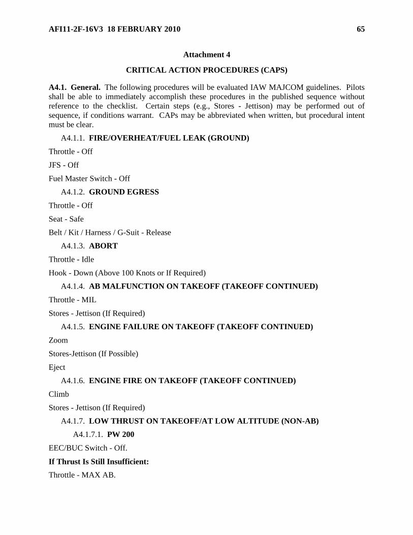
AFI11-2F-16V3 18 FEBRUARY 2010 65
Attachment 4
CRITICAL ACTION PROCEDURES (CAPS)
A4.1. General. The following procedures will be evaluated IAW MAJCOM guidelines. Pilots
shall be able to immediately accomplish these procedures in the published sequence without
reference to the checklist. Certain steps (e.g., Stores - Jettison) may be performed out of
sequence, if conditions warrant. CAPs may be abbreviated when written, but procedural intent
must be clear.
A4.1.1. FIRE/OVERHEAT/FUEL LEAK (GROUND)
Throttle - Off
JFS - Off
Fuel Master Switch - Off
A4.1.2. GROUND EGRESS
Throttle - Off
Seat - Safe
Belt / Kit / Harness / G-Suit - Release
A4.1.3. ABORT
Throttle - Idle
Hook - Down (Above 100 Knots or If Required)
A4.1.4. AB MALFUNCTION ON TAKEOFF (TAKEOFF CONTINUED)
Throttle - MIL
Stores - Jettison (If Required)
A4.1.5. ENGINE FAILURE ON TAKEOFF (TAKEOFF CONTINUED)
Zoom
Stores-Jettison (If Possible)
Eject
A4.1.6. ENGINE FIRE ON TAKEOFF (TAKEOFF CONTINUED)
Climb
Stores - Jettison (If Required)
A4.1.7. LOW THRUST ON TAKEOFF/AT LOW ALTITUDE (NON-AB)
A4.1.7.1. PW 200
EEC/BUC Switch - Off.
If Thrust Is Still Insufficient:
Throttle - MAX AB.

66 AFI11-2F-16V3 18 FEBRUARY 2010
If Thrust Is Still Insufficient:
Throttle - MIL
EEC/BUC Switch - BUC
If Nozzle Fails To Close After Transferring To BUC Or If Thrust Is Still Insufficient:
EEC/BUC Switch - OFF
Throttle - MAX AB
Stores - Jettison (If or When Required)
A4.1.7.2. GE100/129
Throttle - AB.
Stores-Jettison (If Required).
If thrust is insufficient to maintain level flight at a safe altitude:
Engine Control Switch – SEC, then PRI
A4.1.7.3. PW 220/229
Throttle - AB
Stores - Jettison (If Required
If PRI thrust is insufficient to maintain level flight at a safe altitude:
Engine Control Switch - SEC
A4.1.8. ENGINE FAILURE/AIRSTART
A4.1.8.1. PW200
Zoom (If at Low Altitude)
Stores - Jettison (If Required)
Throttle - OFF
Airspeed - As Required
EEC/BUC Switch - As Required.
When RPM Is Between 40-25 Percent And FTIT Is Below 700 Degrees:
Throttle - IDLE
JFS - Start 2 When Below 20,000 Feet and 400 KIAS
A4.1.8.2. PW220
Zoom (If At Low Altitude)
Stores - Jettison (If Required)
Throttle - OFF
Airspeed - As Required.

AFI11-2F-16V3 18 FEBRUARY 2010 67
When RPM Is Between 50-25 Percent And FTIT Is Below 700 Degrees:
Throttle - IDLE
JFS - Start 2 When Below 20,000 Feet and 400 KIAS
A4.1.8.3. PW229
Zoom (If at Low Altitude)
Stores - Jettison (If Required)
Throttle - OFF, then Midrange
Airspeed - As Required
JFS - Start 2 When Below 20,000 Feet and 400 KIAS
A4.1.8.4. GE100/129
Zoom (If at Low Altitude)
Stores - Jettison (If Required)
Engine Control Switch – SEC, Then PRI
Airspeed – As Required
JFS – Start 2 When Below 20,000 Feet and 400 KIAS
A4.1.9. OUT-OF-CONTROL RECOVERY
Controls - Release
Throttle - Idle
FLCS Switch – RESET (Delete this step for analog FLCS)
If In An Inverted Deep Stall:
Rudder - Opposite Yaw Direction (Delete this step for Block 40/42/50/52 aircraft).
If Still Out-Of-Control:
MPO Switch - OVRD and Hold
Stick - Cycle in Phase