by order of the air force manual 91-201 secretary of …
TRANSCRIPT
BY ORDER OF THE
SECRETARY OF THE AIR FORCE
AIR FORCE MANUAL 91-201
12 JANUARY 2011
Incorporating Change 1, 22 June 2012
Safety
EXPLOSIVES SAFETY STANDARDS
COMPLIANCE WITH THIS PUBLICAITON IS MANDATORY
ACCESSIBILITY: This publication is available digitally on the e-Publishing website at
www.e-publishing.af.mil for downloading or ordering
RELEASABILITY: There are no releasability restrictions on this publication.
OPR: AFSC/SEW
Supersedes: AFMAN 91-201, 17
November 2008
Certified by: AF/SED (Mr. Roberto I.
Guerrero)
Pages: 473
This Manual implements Air Force Policy Directive (AFPD) 91-2, Safety Programs, and DoD
6055.09-M, Volumes 1–8, DoD Ammunition and Explosives Safety Standards. It establishes a
central source for explosive safety criteria. It identifies hazards and states safety precautions and
rules when working with explosives. It applies to everyone involved in explosives operations of
any kind at Air Force, Air National Guard and Air Force Reserve-owned or leased facilities and
to US-titled ammunition in contractor or host-nation facilities. Compliance is mandatory, but
only as minimum safety standards. The use of the name or mark of any specific manufacturer,
commercial product, commodity, or service in this publication does not imply endorsement by
the Air Force. Send major command (MAJCOM) supplements to AF/SE, 9700 Avenue G SE,
Kirtland AFB NM 87117-5671, for approval before publication. Send recommended changes on
AF Form 847, Recommendation for Change of Publication, any conflicts with other Air Force
directives as well as general correspondence about the content of this Manual through command
channels to AFSC/SEW, 9700 G Avenue SE, Kirtland AFB NM 87117-5670. Ensure that all
records created as a result of processes prescribed in this publication are maintained in
accordance with AFMAN 33-363, Management of Records, and disposed of in accordance with
the Air Force Records Disposition Schedule (RDS) located at
https://www.my.af.mil/afrims/afrims/afrims/rims.cfm.
SUMMARY OF CHANGES
This interim change implements guidance for handling Joint Test Assemblies, eliminates
MAJCOM interim ESP approval, modifies (Event) Operational Waiver process, clarifies
placarding of multicubes, maintenance of land in and around storage locations, requirements for
2 AFMAN91-201 12 JANUARY 2011
risk assessments, and Airfield deviations, Lightning Protection System design and operational
requirements, and updates Intentional Detonation Site requirements . A margin bar (|) indicates
newly revised material.
Chapter 1—INTRODUCTION AND EXCEPTION PROGRAM 28
Section 1A—Explosives Safety General Instructions 28
1.1. Purpose. .................................................................................................................. 28
1.2. Scope. ..................................................................................................................... 28
Section 1B—Exception Program 30
1.3. General. .................................................................................................................. 30
1.4. Deviations. ............................................................................................................. 31
1.5. Operational Waivers. ............................................................................................. 33
1.6. Waivers. ................................................................................................................. 34
1.7. Exemptions. ........................................................................................................... 34
1.8. SECAF Waivers and Exemptions for New Construction. ..................................... 35
1.9. Exceptions for Non-DoD Explosives Activities on Air Force Installations. ......... 35
1.10. Waiver and Exemption Information Requirements. .............................................. 35
1.11. HAF-Level Waiver and Exemption Information Requirements. ........................... 36
1.12. Waiver or Exemption Decision Nomograph. ......................................................... 37
1.13. Periodic Reviews for Exceptions. .......................................................................... 38
1.14. Cancellation of Waivers and Exemptions. ............................................................. 39
Table 1.1. Likelihood of a Mishap. ......................................................................................... 40
Table 1.2. Exposure. ............................................................................................................... 40
Table 1.3. Possible Consequences of a Mishap. ..................................................................... 41
Table 1.4. Periodic Review Levels for HAF-Level Waivers and Exemptions. ...................... 42
Figure 1.1. Exception Decision Nomograph–Day-to-Day Operations. .................................... 43
Figure 1.2. Exception Decision Nomograph–Contingency and War Plans. ............................ 44
Figure 1.3. Nomograph Plotting Example. ............................................................................... 45
Chapter 2—REACTION EFFECTS 46
Section 2A—Principal Effects of High Density (HD) 1.1 Events 46
2.1. Blast. ...................................................................................................................... 46
2.2. Fragments. .............................................................................................................. 48
2.3. Thermal Hazards. ................................................................................................... 48
AFMAN91-201 12 JANUARY 2011 3
2.4. Groundshock and Cratering. .................................................................................. 48
2.5. Expected Consequences. ........................................................................................ 49
Section 2B—Principal Effects of HD 1.2 Events. 51
2.6. Blast. ...................................................................................................................... 51
2.7. Fragments. .............................................................................................................. 52
2.8. Thermal Hazards. ................................................................................................... 52
2.9. Ejected Items. ......................................................................................................... 52
2.10. Propelled Items. ..................................................................................................... 52
2.11. Firebrands. ............................................................................................................. 52
2.12. Expected Consequences. ........................................................................................ 52
Section 2C—Principal Effects of HD 1.3 Events 53
2.13. Gas Pressures. ........................................................................................................ 53
2.14. Fragments. .............................................................................................................. 53
2.15. Thermal Hazards. ................................................................................................... 53
2.16. Propelled Items. ..................................................................................................... 53
2.17. Firebrands. ............................................................................................................. 53
2.18. Expected Consequences. ........................................................................................ 54
Section 2D—Principal Effects of HD 1.4 Events 54
2.19. Blast. ...................................................................................................................... 54
2.20. Fragments. .............................................................................................................. 54
2.21. Thermal Hazards. ................................................................................................... 54
2.22. Firebrands. ............................................................................................................. 54
2.23. Compatibility Group (CG) S Items. ....................................................................... 54
2.24. Expected Consequences. ........................................................................................ 54
Section 2E—Principal Effects of HD 1.5 and HD 1.6 Events 54
2.25. HD 1.5 Effects. ...................................................................................................... 54
2.26. HD 1.6 Effects. ...................................................................................................... 54
Table 2.1. Expected Peak Incident Pressures From HD 1.1 Events. ...................................... 54
Table 2.2. Probability Of Window Breakage From Incident Pressure. .................................. 55
Table 2.3. General Blast Effects On Personnel–Eardrum Rupture. ........................................ 56
Table 2.4. General Blast Effects On Personnel–Lung Damage. ............................................. 57
Table 2.5. General Blast Effects On Personnel – Lethality Due To Lung Rupture. ............... 57
4 AFMAN91-201 12 JANUARY 2011
Chapter 3—HAZARD CLASSIFICATION 58
Section 3A—DoD Hazard Classification System 58
3.1. Purpose of Hazard Classification. .......................................................................... 58
3.2. Responsibility for Hazard Classification. .............................................................. 58
3.3. Hazard Classification Authorities. ......................................................................... 58
3.4. Standards for Determining DoD Hazard Classification. ........................................ 58
3.5. Description of DoD Hazard Classification System. ............................................... 58
3.6. Net Explosive Weight and Net Explosive Weight for Quantity-Distance. ............ 59
3.7. Requirement for DoD Hazard Classification. ........................................................ 59
Section 3B—Storage and Transportation Without DoD Hazard Classification 60
3.8. Storage and Transportation Without DoD Hazard Classification. ......................... 60
3.9. Explosives With DOE Hazard Classifications. ...................................................... 60
3.10. DoD-Owned Non-Stock-Listed Commercial Explosives. ..................................... 61
3.11. Manufacturing, Research and Development Items. ............................................... 62
3.12. Foreign Explosives. ............................................................................................... 62
3.13. Non-DoD-Owned Explosives. ............................................................................... 63
Section 3C—Hazard Classification of Unpackaged Items 65
3.14. Hazard Classification of Unpackaged Items. ......................................................... 65
Section 3D—Class 1 Divisions and Subdivisions 66
3.15. HD 1.1 – Mass-explosion. ..................................................................................... 66
3.16. HD 1.2 – Non-mass Explosion, Fragment Producing. ........................................... 66
3.17. HD 1.3 – Mass Fire, Minor Blast or Fragment. ..................................................... 67
3.18. HD 1.4 – Moderate Fire, No Significant Blast or Fragment. ................................. 67
3.19. HD 1.5 – Explosive Substance, Very Insensitive (With Mass Explosion Hazard).
................................................................................................................................. 67
3.20. HD 1.6 – Explosive Article, Extremely Insensitive. .............................................. 67
Section 3E—Compatibility Groups and Sensitivity Groups 67
3.21. Storage and Transportation Compatibility Groups. ............................................... 67
3.22. Sensitivity Groups. ................................................................................................. 69
Chapter 4—RISK ASSESSMENTS AND PROTECTION PRINCIPLES 70
Section 4A—Risk Assessments 70
4.1. Requirements for Risk Assessments. ..................................................................... 70
AFMAN91-201 12 JANUARY 2011 5
4.2. Risk Assessments. .................................................................................................. 70
4.3. Risk Management (RM). ....................................................................................... 70
4.4. System Safety. ....................................................................................................... 71
4.5. Professional Assistance for Risk Assessments and System Safety Analyses. ....... 71
Section 4B—Munitions Systems and Equipment 71
4.6. Safety Certification of Munitions Systems. ........................................................... 71
4.7. Risk Assessments for Explosives Equipment. ....................................................... 71
Section 4C—Explosives Operations and Facilities 71
4.8. Risk Assessment for Explosives Operations. ......................................................... 71
4.9. Risk Assessments for Explosives Facilities. .......................................................... 72
Section 4D—Glass Breakage Risk Assessments 72
4.10. Purpose of Glass Breakage Risk Assessments. ...................................................... 72
4.11. Requirements for Performance of Glass Breakage Risk Assessments. ................. 72
4.12. Software Tools for Glass Breakage Risk Assessments. ......................................... 73
4.13. Methodology for Glass Breakage Risk Assessments. ............................................ 74
4.14. Engineering Mitigation Actions for Reducing or Eliminating Glass Breakage
Hazards to Personnel. ............................................................................................ 74
Section 4E—Health Hazard and Environmental Assessments 75
4.15. Health Hazard Assessments. .................................................................................. 75
4.16. Environmental Assessments. ................................................................................. 75
Section 4F—Protection Principles 75
4.17. Protective Shielding and Remotely Controlled Operations. .................................. 75
4.18. Intentional Ignition or Initiation of AE. ................................................................. 76
4.19. Protective Measures. .............................................................................................. 76
4.20. Emergency Operations. .......................................................................................... 77
Figure 4.1. Five Step Process for Risk Management ............................................................... 78
Chapter 5—GENERAL EXPLOSIVES FACILITY DESIGN, CONSTRUCTION AND
MAINTENANCE, AND EQUIPMENT DESIGN, MAINTENANCE AND
INSPECTION 79
Section 5A—Introduction 79
5.1. Applicability. ......................................................................................................... 79
Section 5B—Glass Panels 79
6 AFMAN91-201 12 JANUARY 2011
5.2. Glass Panels in Facilities Exposed to Explosives Hazards. ................................... 79
Section 5C—Hazardous Locations 80
5.3. Hazardous Locations. ............................................................................................. 80
5.4. Electrical Equipment in Hazardous Locations. ...................................................... 80
5.5. Interior Surfaces in Class II Hazardous Locations. ................................................ 81
5.6. Hardware in Hazardous Locations. ........................................................................ 81
5.7. Static Electricity in Hazardous Locations. ............................................................. 81
5.8. Ventilation in Hazardous Locations. ...................................................................... 81
Section 5D—Electric Supply Systems 82
5.9. Electric Supply Systems. ....................................................................................... 82
5.10. Backup Power. ....................................................................................................... 82
Section 5E—Static Grounding and Bonding 82
5.11. Areas Requiring Static Grounding and Bonding Systems. .................................... 82
5.12. Static Grounding and Bonding Requirements. ...................................................... 82
5.13. Permanent Static Grounding Systems. ................................................................... 83
5.14. Temporary Static Grounding or Bonding Cables. ................................................. 84
5.15. Static Grounding or Bonding Reels. ...................................................................... 84
5.16. Belting. ................................................................................................................... 85
Section 5F—Conductive Floors 85
5.17. Areas Requiring Conductive Floors. ...................................................................... 85
5.18. Requirements for Conductive Floors. .................................................................... 85
5.19. Testing and Maintenance of Conductive Floors. ................................................... 85
5.20. Testing and Maintenance of Conductive Footwear. .............................................. 85
Section 5G—Installed Systems and Equipment Grounds 86
5.21. Installed Systems and Equipment Grounds. .......................................................... 86
Section 5H—Lightning Protection Systems 86
5.22. Facilities Requiring Lightning Protection Systems. .............................................. 86
5.23. Lightning Protection System Design. .................................................................... 86
5.24. Lightning Protection System Inspection, Maintenance, Testing, and Training. .... 90
5.25. Lightning Protection System Exceptions. .............................................................. 90
Section 5I—General Design Considerations for Explosives Facilities 92
5.26. Blowout-type Construction. ................................................................................... 92
AFMAN91-201 12 JANUARY 2011 7
5.27. Non-combustible Construction. ............................................................................. 92
5.28. Underground Explosives Storage Facilities. .......................................................... 92
5.29. Outdoor Explosives Storage Sites. ......................................................................... 92
5.30. Stairways. ............................................................................................................... 93
5.31. Fixed Ladders. ....................................................................................................... 93
5.32. Platforms, Runways, and Railings. ........................................................................ 93
5.33. Passageways. .......................................................................................................... 93
5.34. Walkways. .............................................................................................................. 93
5.35. Roads. .................................................................................................................... 93
5.36. Gates. ..................................................................................................................... 93
5.37. Drainage. ................................................................................................................ 94
5.38. Drains and Sumps. ................................................................................................. 94
5.39. Tunnels. .................................................................................................................. 94
5.40. Laundries. .............................................................................................................. 94
5.41. Steam for Explosives Processing or Facility Heating. ........................................... 95
5.42. Magazine Ventilation and Vermin-Resistance. ..................................................... 95
Section 5J—Emergency Exits for Explosives Buildings 96
5.43. General. .................................................................................................................. 96
5.44. Building Exits. ....................................................................................................... 96
5.45. Exit Doors. ............................................................................................................. 96
5.46. Safety Chutes. ........................................................................................................ 97
Section 5K—Explosive Dust Collection Systems 98
5.47. Vacuum Collection. ............................................................................................... 98
5.48. Location of Dry-Type Collection Chambers. ........................................................ 98
5.49. Location of Wet-Type Collection Chambers. ........................................................ 98
5.50. Design and Operation of Collection Systems. ....................................................... 99
Section 5L—Water Supply and Fire Suppression Systems for Explosives Facilities 99
5.51. Water Supply for Explosives Manufacturing Areas and Loading Plants. ............. 99
5.52. Automatic Sprinkler Systems. ............................................................................... 100
5.53. Deluge Systems. ..................................................................................................... 100
Section 5M—Monitoring of Design and Construction of Explosives Facilities 100
5.54. Monitoring of Design of Explosives Facilities. ..................................................... 100
8 AFMAN91-201 12 JANUARY 2011
5.55. Monitoring of Construction of Explosives Facilities. ............................................ 101
Section 5N—Maintenance and Repair of Explosives Facilities and Equipment 101
5.56. Removal of Explosives. ......................................................................................... 101
5.57. Requirements for Maintenance and Repair With Explosives Present. .................. 101
5.58. Maintenance of Explosives Facilities. ................................................................... 102
5.59. Maintenance and Repair in Hazardous Locations. ................................................. 102
5.60. Maintenance and Repair of Hazardous Location Equipment and Electrical
Installations. ........................................................................................................... 102
5.61. Maintenance and Repair of Electrical Equipment. ................................................ 103
5.62. Post-Maintenance and Repair of Explosives Facilities and Equipment. ................ 103
Table 5.1. Lightning Sideflash Policy for Nuclear Weapon Configurations .......................... 103
Chapter 6—PROTECTIVE CONSTRUCTION AND SPECIFIC EXPLOSIVES
FACILITY DESIGNS 104
Section 6A—Introduction 104
6.1. General. .................................................................................................................. 104
6.2. Above Ground Magazines. .................................................................................... 104
6.3. Special Structures. ................................................................................................. 104
6.4. High Performance Magazines and Underground Explosives Facilities. ................ 104
Section 6B—Protective Construction 104
6.5. Purpose of Protective Construction. ...................................................................... 104
6.6. Requirements for Use of Protective Construction. ................................................ 104
Section 6C—Earth-Covered Magazines 106
6.7. Earth-Covered Magazines. ..................................................................................... 106
6.8. Earth-Covered Magazine NEWQD Limits. ........................................................... 106
6.9. Earth-Covered Magazine Design Load Criteria. .................................................... 107
6.10. Earth-Covered Magazine Earth Cover Criteria. ..................................................... 107
6.11. Earth-Covered Magazine Drawings. ...................................................................... 107
Section 6D—Barricaded Open Storage Modules 108
6.12. Barricaded Open Storage Modules. ....................................................................... 108
6.13. Barricaded Open Storage Modules NEWQD and AE Type Limits. ...................... 108
6.14. Barricaded Open Storage Module Design Criteria. ............................................... 109
Section 6E—Barricades 110
AFMAN91-201 12 JANUARY 2011 9
6.15. Barricades. ............................................................................................................. 110
6.16. Barricade Size and Orientation to Prevent Prompt Propagation Due to High-
Velocity, Low-Angle Fragments. .......................................................................... 110
6.17. Barricade Size and Orientation for Barricaded ILD Protection. ............................ 111
6.18. Barricade Size and Orientation for Protection Against Overpressure. .................. 112
6.19. Barricade Construction Materials. ......................................................................... 112
6.20. Barricade Designs. ................................................................................................. 112
6.21. Natural Barricades. ................................................................................................ 112
6.22. Inspection of Barricades. ....................................................................................... 112
Section 6F—Earth-Filled, Steel Bin-Type Barricades for Outside Storage 113
6.23. Earth-Filled, Steel Bin-Type Barricades for Outside Storage. ............................... 113
6.24. ARMCO, Inc. Revetment HD Limits. ................................................................... 113
6.25. Types of ARMCO, Inc. Revetments. ..................................................................... 113
6.26. Requirements for ARMCO, Inc. Revetments. ....................................................... 113
6.27. ARMCO, Inc. Revetment Designs. ........................................................................ 114
Section 6G—Substantial Dividing Walls and Blast Doors 114
6.28. Substantial Dividing Walls. ................................................................................... 114
6.29. Blast Doors. ........................................................................................................... 117
Section 6H—Multicube or Segregated Magazines 117
6.30. Multicube or Segregated Magazines. ..................................................................... 117
Figure 6.1. Typical Eight-Cell Barricaded Open Storage Module. .......................................... 118
Figure 6.2. Determination of Barricade Length and Height to Prevent Prompt Propagation
Due to High-Velocity, Low-Angle Fragments. ..................................................... 119
Figure 6.3. Determination of Barricade Length and Height for Barricaded ILD Protection. ... 120
Table 6.1. HD 1. ...................................................................................................................... 120
Chapter 7—EXPLOSIVES OPERATIONS AND STORAGE 122
Section 7A—Introduction 122
7.1. Introduction. ........................................................................................................... 122
Section 7B—Locally Written Instructions 122
7.2. Locally Written Instructions. ................................................................................. 122
7.3. Contents of Locally Written Instructions. .............................................................. 122
Section 7C—General Requirements for Operations Involving Explosives 123
10 AFMAN91-201 12 JANUARY 2011
7.4. Personnel Qualifications. ....................................................................................... 123
7.5. Personnel Limits. ................................................................................................... 123
7.6. Explosives Limits. ................................................................................................. 124
7.7. Housekeeping. ........................................................................................................ 124
7.8. Smoking. ................................................................................................................ 125
7.9. Handling of Explosives. ......................................................................................... 126
7.10. Portable Equipment. ............................................................................................... 126
Section 7D—Static Grounding 127
7.11. Static Electricity. .................................................................................................... 127
7.12. Requirement for Static Grounding. ........................................................................ 127
7.13. Static Grounding for Handling Unpackaged EEDs. .............................................. 127
7.14. Static Grounding for Aircraft During Explosives Loading and Unloading. .......... 128
7.15. Static Grounding Techniques. ................................................................................ 128
7.16. Methods to Reduce the Hazards of Static Electricity. ........................................... 129
Section 7E—Testing, Procedures Verification, Disassembling and Modifying Explosives Items 130
7.17. Requirements for Test, Disassembly, and Modification of Explosives Items. ...... 130
7.18. Electrical Testing of Explosives Items. ................................................................. 130
7.19. Use of Live Explosives for Weapons System Testing. .......................................... 131
Section 7F—Requirements for Specific Situations 131
7.20. Places of Public Assembly. .................................................................................... 132
7.21. Static or Public Displays. ....................................................................................... 132
7.22. Fireworks Displays and Airshow Events. .............................................................. 132
7.23. Live-fire Demonstrations. ...................................................................................... 134
7.24. Hunting. ................................................................................................................. 134
7.25. Training Involving Blank Ammunition. ................................................................ 135
7.26. Exercises and Training Involving Simulators and Smoke Producing Munitions. . 135
7.27. Training and Exercises Involving Explosives. ....................................................... 137
7.28. Military Working Dog Explosives. ........................................................................ 137
7.29. Repairing Containers. ............................................................................................ 138
7.30. Remotely Controlled Operations. .......................................................................... 138
7.31. Flightline Munitions Holding Areas. ..................................................................... 138
Section 7G—Operations in Explosives Storage Spaces 138
AFMAN91-201 12 JANUARY 2011 11
7.32. Operations in Explosives Storage Spaces Containing Explosives. ........................ 138
Section 7H—Procedures in the Event of Electrical Storms 139
7.33. Local Lightning Warning System. ......................................................................... 139
7.34. Procedures in the Event of Lightning. ................................................................... 139
Section 7I—Explosives Storage Requirements 140
7.35. Selection of Explosives Storage Method. .............................................................. 140
7.36. Explosives Storage in Operating Locations. .......................................................... 140
7.37. Explosives Storage Facility Maintenance. ............................................................. 141
7.38. Explosives Stocks Maintenance. ............................................................................ 141
7.39. Marking of Explosives Stocks. .............................................................................. 141
7.40. Munitions in Austere Areas. .................................................................................. 141
7.41. Privately-owned Ammunition. ............................................................................... 142
7.42. Government Arms and Ammunition. .................................................................... 142
Section 7J—Storage and Compatibility Principles 142
7.43. Storage and Compatibility Principles. ................................................................... 142
7.44. Found-on-Base AE. ............................................................................................... 143
7.45. Dangerously Unserviceable AE. ............................................................................ 143
Section 7K—Mixed Compatibility Group Storage 143
7.46. Mixed Compatibility Group Storage. .................................................................... 143
Table 7.1. Storage Compatibility Mixing Chart. .................................................................... 144
Chapter 8—EXPLOSIVES TRANSPORTATION 147
Section 8A—Introduction 147
8.1. Introduction. ........................................................................................................... 147
Section 8B—Explosives Transportation Standards 147
8.2. Federal Regulation. ................................................................................................ 147
8.3. DoD Directives. ..................................................................................................... 147
8.4. Local Laws Regulating Transportation of Explosives and Dangerous Articles. ... 147
Section 8C—Hazard Classification for Explosives Transportation 147
8.5. Hazard Classification Requirements for Transportation. ....................................... 147
8.6. Commercial Explosives Hazard Classification Requirements for Transportation. 148
8.7. Compatibility of Explosives During Transportation. ............................................. 148
8.8. Compatibility of Explosives During Temporary Storage. ..................................... 149
12 AFMAN91-201 12 JANUARY 2011
Section 8D—Packaging for Explosives Transportation 149
8.9. Packaging. .............................................................................................................. 149
8.10. Shipment of Explosives Which Have Been Damaged or Failed To Function. ...... 150
8.11. Transporting Dangerously Unserviceable Explosive Items for Disposal. ............. 150
Section 8E—Explosives Movement Routes on Base 150
8.12. Explosives Movement Routes on Base. ................................................................. 150
Section 8F—Incoming and In-transit Explosives Shipments 150
8.13. Incoming Explosives Shipments. ........................................................................... 150
8.14. In-transit Explosives Shipments/Secure Holding. ................................................. 150
8.15. Inspection of Incoming Explosives Shipments. ..................................................... 151
8.16. Inspection of Outgoing Explosives Shipments. ..................................................... 151
8.17. Interchange Yards. ................................................................................................. 152
8.18. Holding Yards. ....................................................................................................... 152
8.19. Classification Yards. .............................................................................................. 152
8.20. AE Transportation Mode Change Locations. ........................................................ 152
Section 8G—Transportation and Movement of Explosives by Motor Vehicle and Material
Handling Equipment 152
8.21. General. .................................................................................................................. 152
8.22. Transporting Explosives in Passenger Compartments. .......................................... 152
8.23. Transporting Electro-Explosive Devices. .............................................................. 153
8.24. Transporting Aircraft Seats and Survival Kits. ...................................................... 153
8.25. Packaging. .............................................................................................................. 153
8.26. Placarding. ............................................................................................................. 153
8.27. Motor Vehicle Inspection. ..................................................................................... 154
8.28. Load Protection and Stability. ................................................................................ 154
8.29. Loading and Unloading. ......................................................................................... 155
8.30. Vehicle Refueling. ................................................................................................. 155
8.31. Battery-Powered Materials Handling Equipment. ................................................. 156
8.32. Gasoline or Diesel-Powered Materials Handling Equipment. ............................... 156
8.33. Liquefied Petroleum and Compressed Natural Gas Fueled Vehicles. ................... 156
8.34. Exposed Explosives Precautions. ........................................................................... 156
8.35. Storage of Powered Materials Handling Equipment. ............................................. 157
8.36. Operating Powered Materials Handling Equipment Inside Structures. ................. 157
AFMAN91-201 12 JANUARY 2011 13
8.37. Maintenance of Vehicles Carrying Explosives. ..................................................... 157
Section 8H—Transportation of Explosives by Rail 157
8.38. General. .................................................................................................................. 157
8.39. Movement of Railcars Containing Explosives. ...................................................... 158
8.40. Spotting Railcars. ................................................................................................... 158
8.41. Switching Railcars. ................................................................................................ 158
8.42. Marking Railcars with Blue Flags or Signals. ....................................................... 158
8.43. Loading Railcars. ................................................................................................... 159
8.44. Loading and Bracing. ............................................................................................. 159
8.45. Placarding of Railcars. ........................................................................................... 159
8.46. Railcar Requirements. ............................................................................................ 159
8.47. Leaking Packages in Railcars. ............................................................................... 160
8.48. Tools for Loading and Unloading Railcars. ........................................................... 160
8.49. Sealing Railcars. .................................................................................................... 160
8.50. Processing Incoming Loaded Railcars. .................................................................. 160
8.51. Rail Interchange Yards. ......................................................................................... 161
8.52. Rail Holding Yards. ............................................................................................... 161
8.53. Rail Classification Yards. ...................................................................................... 162
8.54. Trailers on Flat Cars or Piggyback Explosives Loading and Unloading. .............. 162
Section 8I—Transportation of Explosives by Air and Water 162
8.55. Transportation of Explosives by Air. ..................................................................... 162
8.56. Transportation of Explosives by Water. ................................................................ 162
Chapter 9—PROTECTION OF ELECTRO-EXPLOSIVE DEVICES FROM HAZARDS
OF ELECTROMAGNETIC RADIATION TO ORDNANCE (HERO) 163
Section 9A—Hazards of Electromagnetic Radiation to Electro-Explosive Devices 163
9.1. Chapter Overview. ................................................................................................. 163
9.2. Conducted Electromagnetic Energy. ..................................................................... 163
Section 9B—Definitions and Conversion Formulas 163
9.3. Antenna Gain (Gt). ................................................................................................ 163
9.4. EED Susceptibility Terms. ..................................................................................... 163
9.5. Effective Isotropic Radiated Power (EIRP). .......................................................... 164
9.6. Electromagnetic Environment (EME). .................................................................. 164
14 AFMAN91-201 12 JANUARY 2011
9.7. Far Field/Far Field Distance (Rff). ........................................................................ 164
9.8. Frequency (f). ......................................................................................................... 164
9.9. HERO Certification. .............................................................................................. 164
9.10. HERO Classifications. ........................................................................................... 165
9.11. Modern Mobile Emitters (MME). .......................................................................... 165
9.12. Near Field. ............................................................................................................. 165
9.13. Safe Separation Distance (SSD). ........................................................................... 165
9.14. Traditional Fixed-Location Emitters (TFE). .......................................................... 166
9.15. Transmitted Power (Pt). ......................................................................................... 166
Section 9C—HERO Protection Overview 166
9.16. Radiated Electromagnetic Energy. ......................................................................... 166
9.17. EMR Protection Information. ................................................................................ 166
9.18. EMR Information Categories. ................................................................................ 166
Figure 9.1. Categories of EMR Information involved in protecting EEDs. ............................. 167
9.19. Use of EMR Information. ...................................................................................... 167
Section 9D—Responsibilities for EMR Analyses 167
9.20. Base-level Safety Office. ....................................................................................... 167
9.21. Command-level Safety Office. .............................................................................. 167
9.22. Communications Squadron and Installation Spectrum Manager (ISM). ............... 168
9.23. Headquarters Air Force Safety Center/Weapons Division (AFSC/SEW). ............ 168
9.24. Civil Engineering Office (CE). .............................................................................. 168
9.25. Munitions Squadron/Flight. ................................................................................... 168
Section 9E—Emitter Categories and Assumptions 169
9.26. Traditional Fixed-Location Emitter (TFE) Analysis. ............................................ 169
9.27. Modern Mobile Emitter (MME) Analysis. ............................................................ 169
Section 9F—Methods for Protecting EEDs from EMR Hazards 170
9.28. TFE Safety Procedures for Conventional Weapons and Individual EEDs. ........... 170
9.29. TFE Safety Procedures for Nuclear Weapons. ...................................................... 172
9.30. MME Safety Procedures and Considerations. ....................................................... 172
9.31. Maximum Power Density Criteria. ........................................................................ 173
Section 9G—Assistance for EMR Analyses 174
9.32. Assistance Requests. .............................................................................................. 174
AFMAN91-201 12 JANUARY 2011 15
9.33. Software Tool. ....................................................................................................... 175
Section 9H—Deviations to EMR Requirements 175
9.34. Deviations to EMR Requirements. ........................................................................ 175
Table 9.1. Recommended Power Densities and SSDs for HERO SUSCEPTIBLE Munitions.
................................................................................................................................. 175
Table 9.2. Recommended EED Power Densities and SSDs for Nuclear Weapons. ............... 177
Figure 9.2. Recommended SSD for HERO SUSCEPTIBLE Munitions; ―Exposed‖
Configuration. ........................................................................................................ 179
Figure 9.3. Example: Recommended SSD for HERO SUSCEPTIBLE Munitions; ―Exposed‖
Configuration. ........................................................................................................ 180
Figure 9.4. Recommended SSD for HERO SUSCEPTIBLE Munitions; ―In Storage or
Ground Transport in a Non-Metallic Container‖ Configuration. ........................... 181
Chapter 10—FIREFIGHTING, EMERGENCY PLANNING AND FIRE PREVENTION 182
Section 10A—Hazard Identification for Firefighting and Emergency Planning 182
10.1. Scope and Applicability. ........................................................................................ 182
10.2. Fire Divisions. ........................................................................................................ 182
10.3. Fire Division Symbols. .......................................................................................... 182
10.4. Chemical Agent and Chemical Munition Hazard Symbols. .................................. 182
10.5. Obtaining Firefighting Symbol Decals. ................................................................. 184
Section 10B—Posting Firefighting Symbols 184
10.6. Purpose of Posting Firefighting Symbols. ............................................................. 184
10.7. Posting Requirements for Firefighting Symbols. ................................................... 184
10.8. Exceptions to Posting Firefighting Symbols. ......................................................... 185
Section 10C—Firefighting Measures and Withdrawal Distances 185
10.9. Firefighting Measures. ........................................................................................... 185
10.10. Fire Withdrawal Distances. .................................................................................... 186
10.11. Improvised Explosive Device Withdrawal Distances. ........................................... 187
10.12. Withdrawal Distances for AE Not Involved in Fire. ............................................. 187
Section 10D—Emergency Planning 187
10.13. Emergency Planning. ............................................................................................. 187
10.14. Fire Drills. .............................................................................................................. 188
Section 10E—Fire Prevention 188
10.15. Heat-Producing Devices. ....................................................................................... 188
16 AFMAN91-201 12 JANUARY 2011
10.16. Vegetation Control. ................................................................................................ 188
10.17. Firebreaks. .............................................................................................................. 188
10.18. Controlled Burning. ............................................................................................... 188
10.19. Flammable Liquids for Cleaning. .......................................................................... 189
10.20. Paint and Other Flammable Materials. .................................................................. 189
10.21. Operating Support Equipment. .............................................................................. 189
10.22. Stacking Combustible Material. ............................................................................. 190
10.23. Fire Extinguishers. ................................................................................................. 190
10.24. Storing Water for Firefighting. .............................................................................. 191
Table 10.1. Fire Division Hazards and Actions. ....................................................................... 191
Table 10.2. Compatibility Group and Chemical Hazard Symbols Required for Storage of
Chemical Ammunition and Substances. ................................................................ 191
Table 10.3. Fire Withdrawal Distances for Non-essential Personnel. 1 ................................... 192
Figure 10.1. Fire Division Symbols. .......................................................................................... 194
Figure 10.2. Chemical Hazard Symbols. .................................................................................... 195
Figure 10.3. Supplemental Chemical Hazard Symbols. ............................................................. 196
Chapter 11—LICENSED EXPLOSIVES STORAGE LOCATIONS 197
Section 11A—Purpose and Limitations for Licensed Explosives Storage Locations 197
11.1. Purpose of Licensed Explosives Storage Locations. ............................................. 197
11.2. General Limitations on AE in Licensed Explosives Storage Locations. ............... 197
11.3. NEWQD Limitations on AE in Licensed Explosives Storage Locations. ............. 197
Section 11B—Requirements for Licensed Explosives Storage Locations 197
11.4. General Requirements for Licensed Explosives Storage Locations. ..................... 198
11.5. Separation Requirements for Licensed Explosives Storage Locations. ................. 198
Section 11C—Documentation for Licensed Explosives Storage Locations 198
11.6. AF Form 2047. ....................................................................................................... 199
11.7. Instructions for Completing AF Form 2047. ......................................................... 199
11.8. Maintaining the AF Form 2047. ............................................................................ 200
Section 11D—Operations Involving AE Stored in Licensed Explosives Storage Locations 200
11.9. Operations Involving AE Stored Licensed Explosives Storage Locations. ........... 201
Section 11E—Requirements for Specific Licensed Explosives Storage Locations 201
11.10. Mobility Storage. ................................................................................................... 201
AFMAN91-201 12 JANUARY 2011 17
11.11. Training and Exercises. .......................................................................................... 201
11.12. Control Tower. ....................................................................................................... 201
11.13. Aircrew Flight Equipment. .................................................................................... 201
11.14. Riot Control Items. ................................................................................................ 201
11.15. Egress Systems Maintenance Shops. ..................................................................... 202
11.16. Gun Systems and Maintenance Shops. .................................................................. 202
11.17. Incendiary Equipment and Document Destroyers. ................................................ 202
11.18. Rod and Gun Clubs. ............................................................................................... 203
11.19. Retail Stores. .......................................................................................................... 203
11.20. Hand Loading. ....................................................................................................... 203
11.21. Force Support Squadron Activities (formerly MWR Activities). .......................... 204
11.22. Minuteman Handling Team Facility. ..................................................................... 204
11.23. Research and Development Laboratories for Specific Experiments. ..................... 205
11.24. Base Defense Support Munitions for Dispersed Locations. .................................. 205
Section 11F—Items or Situations not Requiring a License 205
11.25. Items or Situations not Requiring a License. ......................................................... 205
Figure 11.1. AF Form 2047, Explosives Facility License. ......................................................... 205
Chapter 12—QUANTITY-DISTANCE CRITERIA 207
Section 12A—Introduction 207
12.1. Introduction. ........................................................................................................... 207
Section 12B—Quantity-Distance Principles 207
12.2. General. .................................................................................................................. 207
12.3. Types of Separations. ............................................................................................. 207
Section 12C—Determining Net Explosive Weight for Quantity-Distance 209
12.4. Determining NEWQD of AE Items. ...................................................................... 209
12.5. Determining NEWQD of a PES. ........................................................................... 209
12.6. Maximum NEWQD. .............................................................................................. 210
12.7. Determining NEWQD for Mixed HD. ................................................................... 210
Section 12D—Determining Distances Between PESs and ESs 211
12.8. General. .................................................................................................................. 211
12.9. Measuring from a PES. .......................................................................................... 211
12.10. Measuring to an ES. ............................................................................................... 211
18 AFMAN91-201 12 JANUARY 2011
Section 12E—Quantity-Distance Application 212
12.11. Quantity-Distance K-Factors. ................................................................................ 212
12.12. Paired Relationships. ............................................................................................. 212
12.13. QD Determination. ................................................................................................. 213
Section 12F—Allowable Exposures 213
12.14. General. .................................................................................................................. 214
12.15. Allowable IBD Exposures. .................................................................................... 214
12.16. Allowable PTRD Exposures. ................................................................................. 217
12.17. Allowable Unbarricaded ILD Exposures. .............................................................. 219
12.18. Allowable Barricaded ILD Exposures. .................................................................. 222
12.19. Allowable IMD Exposures. ................................................................................... 223
12.20. Other Allowable Exposures. .................................................................................. 223
Section 12G—Hazard Zones for ECMs and HASs 224
12.21. Hazard Zones for ECMs and HASs. ...................................................................... 224
Section 12H—HD 1. 224
12.22. HD 1.1 Hazardous Fragment Distances. ................................................................ 224
12.23. HD 1.1 IBD and PTRD. ......................................................................................... 226
12.24. HD 1.1 ILD. ........................................................................................................... 228
12.25. HD 1.1 IMD. .......................................................................................................... 229
Section 12I—HD 1.2 QD Criteria 229
12.26. HD 1.2.1 and 1.2.2 QD Criteria. ............................................................................ 229
12.27. HD 1.2.3 QD Criteria. ............................................................................................ 230
Section 12J—HD 1.3 QD Criteria 231
12.28. HD 1.3 QD Criteria. ............................................................................................... 231
Section 12K—HD 1.4 QD Criteria 231
12.29. HD 1.4 QD Criteria. ............................................................................................... 231
Section 12L—HD 1.6 QD Criteria 231
12.30. HD 1.6 QD Criteria. ............................................................................................... 232
Section 12M—HD 6.1 Criteria 232
12.31. HD 6.1 Criteria. ..................................................................................................... 232
Section 12N—Energetic Liquids QD Criteria 232
12.32. Scope and Application. .......................................................................................... 232
AFMAN91-201 12 JANUARY 2011 19
12.33. Concept. ................................................................................................................. 232
12.34. Determination of Energetic Liquids Quantity. ....................................................... 233
12.35. Measurement of Separation Distances. .................................................................. 233
12.36. Hazard Classification of Energetic Liquids. .......................................................... 233
12.37. QD Standards. ........................................................................................................ 237
12.38. Contaminated Energetic Liquids. ........................................................................... 237
Section 12O—QD Criteria Specific Facilities and Systems 238
12.39. General Airfield Criteria. ....................................................................................... 238
12.40. Combat Aircraft Related Activities. ...................................................................... 238
12.41. Explosives Cargo Aircraft Related Activities. ....................................................... 239
12.42. Munitions or Weapons Storage Area Related Activities. ...................................... 240
12.43. Concurrent Servicing Operations. .......................................................................... 240
12.44. Hot-Pit Refueling Operations. ............................................................................... 240
12.45. End-of-Runway and Arm/De-arm Pads and Crew Shelters. .................................. 240
12.46. Aircraft NEWQD. .................................................................................................. 240
12.47. Explosives Aircraft Exempt from Siting as a PES. ................................................ 241
12.48. Deleted. .................................................................................................................. 241
12.49. Other Aircraft Configurations. ............................................................................... 241
12.50. Reduced MCEs for F-15 and F-16 Aircraft with AIM Series Missiles. ................ 241
12.51. Hardened Aircraft Shelters (HAS) and Associated AE Facilities. ......................... 242
12.52. Weapons Storage Vaults in Hardened Aircraft Shelters. ....................................... 244
12.53. Revetments. ............................................................................................................ 244
12.54. Aircraft Battle Damage Repair Sites. ..................................................................... 244
12.55. Helicopter Landing Areas for AE Operations. ....................................................... 244
12.56. Defensive or Tactical Missile Batteries. ................................................................ 245
12.57. Tactical Missile Separations. ................................................................................. 245
12.58. Inspection Stations for AE Conveyances. .............................................................. 248
12.59. Interchange Yards for AE Conveyances. ............................................................... 248
12.60. Holding Yards for AE Conveyances. ..................................................................... 248
12.61. Classification Yards. .............................................................................................. 249
12.62. AE Transportation Mode Change Locations. ........................................................ 250
12.63. Suspect Vehicle Holding Areas. ............................................................................ 250
12.64. Secure Holding Areas. ........................................................................................... 250
20 AFMAN91-201 12 JANUARY 2011
12.65. Detached Loading Docks. ...................................................................................... 250
12.66. Service Magazines for Operating Locations. ......................................................... 250
12.67. Non-Explosives Loaded Vehicle Parking Areas. ................................................... 251
12.68. Inert Storage. .......................................................................................................... 251
12.69. Protective Shielding and Remotely Controlled Operations. .................................. 252
12.70. Deleted. .................................................................................................................. 252
12.71. Buffered Storage. ................................................................................................... 252
12.72. Angled Storage. ..................................................................................................... 253
12.73. Areas for Burning AE. ........................................................................................... 254
12.74. Areas Used for Intentional Detonations. ................................................................ 254
12.75. EOD Operational Responses. ................................................................................. 257
12.76. EOD Proficiency Training Ranges. ....................................................................... 257
12.77. EOD Training at Off-Range Locations. ................................................................. 258
12.78. Static Test Firing Propellant Loaded Items. .......................................................... 259
12.79. Military Working Dog (MWD) Explosives Search Training. ............................... 260
12.80. Demilitarization Operations for Expended 50-Caliber and Smaller Cartridge
Casings.. ................................................................................................................. 260
12.81. POL and Other Hazardous Materials. .................................................................... 261
12.82. Storage Tanks for Water and Other Non-Hazardous materials . ........................... 262
12.83. Underground Tanks or Pipelines for Water and Other Non-Hazardous Materials. 263
12.84. Utilities and Services. ............................................................................................ 263
12.85. LGM-30 (Minuteman). .......................................................................................... 264
12.86. LGM-118 (Peacekeeper). ....................................................................................... 265
12.87. Inter-DoD Component Support and Tactical Facilities. ........................................ 265
12.88. Criteria for non-DoD Explosives Activities on DoD Installations. ....................... 266
Section 12P—-Space and Intercontinental Ballistic Missile Requirements 266
12.89. General Information. .............................................................................................. 266
12.90. Support Facilities. .................................................................................................. 267
12.91. Safety Control Area. .............................................................................................. 268
12.92. Simultaneous Operations. ...................................................................................... 268
12.93. Barricades. ............................................................................................................. 268
12.94. Space Launch Complex. ........................................................................................ 268
12.95. Space Test Facilities. ............................................................................................. 269
AFMAN91-201 12 JANUARY 2011 21
12.96. Risk Management. ................................................................................................. 269
12.97. Space and Intercontinental Ballistic Missile Criteria. ............................................ 271
Figure 12.1. Hazard Zones for ECMs. ....................................................................................... 276
Figure 12.2. ECM Orientation Effects on IMD. ......................................................................... 278
Figure 12.2. ECM Orientation Effects on IMD (Continued). .................................................... 278
Figure 12.3. Hazard Zones for HASs. ........................................................................................ 278
Figure 12.4. F-15 Aircraft QD Separation Distances for Selected AIM/AGM Series Missile
Configurations. ...................................................................................................... 280
Figure 12.5. F-16 Aircraft QD Separation Distances for Selected AIM/AGM Series Missile
Configurations. ...................................................................................................... 281
Figure 12.6. Reduced MCEs and QDs for F-15 Aircraft in the Open 1,2,3,4,5 ......................... 282
Figure 12.7. Reduced MCEs and QDs for F-16 Aircraft in the Open 1,2,3,4,5 ......................... 284
Figure 12.8. Fragment Zones for General Purpose Bombs. ....................................................... 285
Table 12.1. HD 1.1 QD Criteria Notes (12) (24) ...................................................................... 288
Table 12.1. HD 1.1 QD Criteria Notes (12) (24) (continued) ................................................... 288
Table 12.1. HD 1.1 QD Criteria Notes (12) (24) (continued) ................................................... 288
Table 12.2. HD 1.2.1, 1.2.2, and 1.2.3 QD Criteria NOTES (1) (2) (3) ................................... 291
Table 12.2. HD 1.2.1, 1.2.2, and 1.2.3 QD Criteria NOTES (1) (2) (3) (continued) ................ 291
Table 12.3. HD 1.3, 1.4 and 1.6 QD Criteria. NOTES (1) (10) (11) ........................................ 296
Table 12.3. HD 1.3, 1.4 and 1.6 QD Criteria. NOTES (1) (10) (11) (continued) ..................... 296
Table 12.4. HD 1.1 Default Hazardous Fragment Distances (HFD) for IBD. .......................... 299
Table 12.5. HFD for Open Stacks of Selected HD 1.1 AE ....................................................... 300
Table 12.6. HD 1.1 IBD and PTRD. ......................................................................................... 301
Table 12.7. HD 1.1 ILD from an ECM. .................................................................................... 304
Table 12.8. HD 1.1 ILD other than ECM. ................................................................................ 305
Table 12.9. HD 1.2.1 QD in the Open. ..................................................................................... 306
Table 12.10. HDD for HD 1.2.1 Stored in Structures Which Can Contribute to the Debris
Hazard. ................................................................................................................... 307
Table 12.11. HD 1.2.2 QD. 5 ...................................................................................................... 308
Table 12.12. HD 1.3 QD. 6 ......................................................................................................... 309
Table 12.13. HD 1.4 QD. 1,8 ...................................................................................................... 310
Table 12.14. HD 1.6 QD. 1 ......................................................................................................... 312
Table 12.15. Hazard Classifications and Minimum QD for Energetic Liquids. ......................... 313
Table 12.16. Factors to Use When Converting Energetic Liquid Densities. .............................. 314
22 AFMAN91-201 12 JANUARY 2011
Table 12.17. Energetic Liquid Explosive Equivalents. 1,2, 3, 4, 5 ............................................. 315
Table 12.18. QD Criteria for OSHA/NFPA Class I – III Flammable and Combustible
Energetic Liquids Storage in Detached Buildings or Tanks. 1,2 ........................... 316
Table 12.19. QD Criteria for Energetic Liquid Oxidizer (excluding Liquid Oxygen) Storage in
Detached Buildings or Tanks. 1, 2 ......................................................................... 317
Table 12.20. QD Criteria for Liquid Oxygen Storage in Detached Buildings or Tanks. 1, 2 ..... 318
Table 12.21. QD Criteria for Liquid Hydrogen and Bulk Quantities of Hydrazines 1 ............... 319
Table 12.22. HD 1.1 QD for Military Aircraft Parking Areas. ................................................... 320
Table 12.23. HAS Separation Criteria to Prevent Simultaneous Detonation 1,2,3 ..................... 321
Table 12.23A. HAS Separation Criteria to Prevent Simultaneous Detonation (continued) 1,2,3 . 322
Table 12.24. HAS Separation Criteria for Asset Preservation 1,2,3 ........................................... 323
Table 12.24A. HAS Separation Criteria for Asset Preservation (continued) 1,2,3 ....................... 324
Table 12.25A. QD from a Third Generation HAS PES to an Unhardened ES. 1,2,3 .................... 325
Table 12.25B. QD from a First Generation HAS PES to an Unhardened ES. 1,2,3 ..................... 325
Table 12.26A. Default Maximum Case Fragment Distances Versus Diameter for Intentional
Detonations. ........................................................................................................... 328
Table 12.26A. Default Maximum Case Fragment Distances Versus Diameter for Intentional
Detonations (Continued). ....................................................................................... 328
Table 12.26A. Default Maximum Case Fragment Distances Versus Diameter for Intentional
Detonations (Continued). ....................................................................................... 328
Table 12.26B. Default Maximum Case Fragment Distances Versus Net Explosive Weight for
Intentional Detonations. ......................................................................................... 332
Table 12.26B. Default Maximum Case Fragment Distances Versus Net Explosive Weight for
Intentional Detonations (Continued). ..................................................................... 332
Table 12.26B. Default Maximum Case Fragment Distances Versus Net Explosive Weight for
Intentional Detonations (Continued). ..................................................................... 332
Table 12.27. Minuteman TNT Equivalencies. ............................................................................ 333
Table 12.28. Peacekeeper TNT Equivalencies. .......................................................................... 334
Table 12.29. Criteria for Non-DoD Explosives Activities on DoD Installations. ...................... 334
Table 12.30. QD for HD 1.1 AE For K = 1.1, 1.25, 2, 2.75, 4.5, and 5. ..................................... 334
Table 12.31. QD for HD 1.1 AE For K = 6, 8, 9, 11, 18, 40. ..................................................... 335
Chapter 13—CONTINGENCIES, COMBAT OPERATIONS, MILITARY OPERATIONS 336
Section 13A—Introduction 336
13.1. Introduction. ........................................................................................................... 336
13.2. Scope. ..................................................................................................................... 336
AFMAN91-201 12 JANUARY 2011 23
13.3. Contingencies, Combat Operations, MOOTW, and Associated Training. ............ 336
13.4. Asset Preservation and Minimum Separation Distances. ...................................... 336
Section 13B—Planning for Deployments 337
13.5. Planning for Deployments. .................................................................................... 337
Section 13C—Risk Management 338
13.6. Risk Management. ................................................................................................. 338
Section 13D—Explosives Site Planning 338
13.7. Site Approval. ........................................................................................................ 338
13.8. Site Approval and Documentation Requirements. ................................................. 339
13.9. Explosives Site Plan Packages. .............................................................................. 340
13.10. Approval Authority for Exceptions. ...................................................................... 340
Section 13E—QD Criteria for Contingencies, Combat Operations, MOOTW and Associated
Training 341
13.11. Basic Load Ammunition Holding Area (BLAHA). ............................................... 341
13.12. Ports. ...................................................................................................................... 342
13.13. Field Storage and Handling Areas. ........................................................................ 343
13.14. Forward Arming and Refueling Point (FARP). ..................................................... 344
13.15. Airfield Operations. ............................................................................................... 345
13.16. Static Missile Battery Separation. .......................................................................... 345
13.17. Emergency Destruction. ......................................................................................... 346
13.18. Separation From Fuel. ............................................................................................ 346
Table 13.1. QD for BLAHA and BLSA. .................................................................................. 346
Table 13.2. QD Requirements for Armored Vehicles. 1,2,3 ..................................................... 348
Table 13.3. QD for Field Storage and Handling Areas. 1,2 ...................................................... 349
Table 13.4. QD for Contingency, Combat, and MOOTW Airfields. ........................................ 350
Chapter 14—EXPLOSIVES SITE PLANNING 351
Section 14A—Introduction 351
14.1. Purpose of Explosives Site Planning. .................................................................... 351
14.2. Responsibilities for Explosives Site Planning. ...................................................... 351
Section 14B—Explosives Clear Zones 351
14.3. Explosives Clear Zones. ......................................................................................... 351
14.4. Monitoring of Explosives Clear Zones. ................................................................. 351
24 AFMAN91-201 12 JANUARY 2011
14.5. Mapping Requirements for Explosives Clear Zones. ............................................ 351
14.6. Reduction or Re-designation of Explosives Clear Zones. ..................................... 351
Section 14C—Explosives Site Plans 352
14.7. Explosives Site Plans. ............................................................................................ 352
14.8. Funding for Projects Requiring Explosives Site Plans. ......................................... 352
14.9. Situations Requiring Explosives Site Plans. .......................................................... 352
14.10. Situations Not Requiring Explosives Site Plans. ................................................... 352
14.11. Facility Modifications or Change in Use. .............................................................. 353
14.12. Explosives Site Plan Development and Installation-level Coordination. .............. 354
14.13. Explosives Site Plan Contents. .............................................................................. 355
14.14. Explosives Site Plan Submission and MAJCOM and Air Force-level
Coordination Process. ............................................................................................ 355
14.15. Explosives Site Plan Approval. .............................................................................. 356
14.16. Maintenance of Approved Explosives Site Plans. ................................................. 357
Section 14D—Explosives Site Plan Requirements 357
14.17. Explosives Site Plans for Non-DoD Explosives Activities on Air Force
Installations. ........................................................................................................... 357
14.18. Siting a Non-Explosives Exposed Site. ................................................................. 358
14.19. Explosives Site Plans Involving Exceptions. ......................................................... 358
14.20. Tiered Explosives Site Plans. ................................................................................. 358
14.21. Components of the Explosives Site Plan. .............................................................. 359
14.22. Transmittal Letter. ................................................................................................. 359
14.23. AF Form 943. ......................................................................................................... 362
14.24. Site Location Map. ................................................................................................. 364
14.25. Construction Drawings and Structural Engineering Analyses. .............................. 364
14.26. Automated Explosives Site Planning. .................................................................... 366
Section 14E—Deleted 366
14.27. Alternative AF Form 943 Formats. ........................................................................ 366
Figure 14.1. Evaluation Zone Examples. ................................................................................... 367
Figure 14.2. Instructions for Filling out AF Form 943. ............................................................. 368
Figure 14.3. AF Form 943. ......................................................................................................... 369
Figure 14.4. Sample Site Location Map. .................................................................................... 373
AFMAN91-201 12 JANUARY 2011 25
CHAPTER 15—REAL PROPERTY KNOWN OR SUSPECTED TO CONTAIN
MUNITIONS AND EXPLOSIVES OF CONCERN AND CHEMICAL
AGENTS 374
Section 15A—Introduction 374
15.1. General. .................................................................................................................. 374
Section 15B—Explosives Safety Standards for the Identification and Control of Areas Known or
Suspected to Contain MEC or CA 374
15.2. Identification and Control. ..................................................................................... 375
Section 15C—Safety Aspects of Explosives and CA Response Actions 376
15.3. Response Actions ................................................................................................... 376
Section 15D—Special Considerations 379
15.4. General ................................................................................................................... 379
Table 15.1. Hazardous Waste Control Limits (HWCL) ........................................................... 383
Table 15.2. Health-Based Environmental Screening Levels (HBESL) .................................... 384
Section 15E—Required Safety Submissions (ESS, CSS and Explosives or CWM Site Plans) 384
15.5. General. .................................................................................................................. 384
Section 15F—Amendments and Corrections 395
15.6. General. .................................................................................................................. 395
Section 15G—After Action Reports (AAR) 396
15.7. General ................................................................................................................... 396
Section 15H—Transfer of Real Property Outside DoD Control 397
15.8. General. .................................................................................................................. 397
Chapter 16—SPECIAL STORAGE PROCEDURES FOR WASTE MILITARY
MUNITIONS 399
Section 16A—Scope and Applicability 399
16.1. Scope and Applicability. ........................................................................................ 399
Section 16B—General 399
16.2. General. .................................................................................................................. 399
Section 16C—Waivers and Exemptions 400
16.3. Waivers and Exemptions. ...................................................................................... 400
Section 16D—Storage Requirements 400
16.4. Requirements for Storage of Waste Military Munitions Under CE. ...................... 400
26 AFMAN91-201 12 JANUARY 2011
Section 16E—Loss of CE 401
16.5. Loss of CE. ............................................................................................................ 401
16.6. Other Storage Standards. ....................................................................................... 401
16.7. Un-Permitted and Uncontrolled Loss Reporting. .................................................. 402
Section 16F—Closure of Facilities Storing Waste Munitions 402
16.8. Closure of Facilities Storing Waste Munitions Under CE. .................................... 402
16.9. Discontinuance of use for the Storage of Waste Munitions. .................................. 403
16.10. Closure of Facilities Storing Waste Military Munitions Under RCRA. ................ 403
CHAPTER 17—UNEXPLODED ORDNANCE (UXO) 404
Section 17A—Introduction 404
17.1. This chapter establishes standards to protect personnel and property from
explosive and chemical agent (CA) hazards associated with UXO or other
military munitions, to include discarded military munitions (DMM), that have
experienced abnormal environments. .................................................................... 404
17.2. General ................................................................................................................... 404
Section 17B—Disposition 405
17.3. Disposition of UXO and of Other Military Munitions Being Managed as UXO .. 405
Section 17C—Special Considerations 408
17.4. General ................................................................................................................... 408
Section 17D—Access to UXO Areas 410
17.5. Access to Areas Known or Suspected to Contain UXO. ....................................... 410
Section 17E—Identification and Control 412
17.6. To ensure explosives and CA safety risk is identified and controlled on real
property currently or formerly under the jurisdiction, custody, or control of the
USAF, Installation Commanders must create and maintain permanent records
required by paragraph 15.2.2. ................................................................................ 412
17.7. Minimum Separation Distance (MSD) for UXO ................................................... 412
Section 17F—Other Considerations 412
17.8. General ................................................................................................................... 412
Section 17G—Prescribed and Adopted Forms 414
17.9. Prescribed Forms. .................................................................................................. 414
17.10. Adopted Forms. ..................................................................................................... 414
AFMAN91-201 12 JANUARY 2011 27
ATTACHMENT 1—GLOSSARY OF REFERENCES AND SUPPORTING
INFORMATION 415
Attachment 2—SAMPLE EXPLOSIVES SITE PLAN TRANSMITTAL LETTER. 462
Attachment 3—SAMPLE NARRATIVE FOR AIR FORCE QUANTITY-DISTANCE
EXCEPTION REQUEST 464
ATTACHMENT 4—SELECTED SECRETARY OF THE AIR FORCE EXEMPTIONS 465
Attachment 5—QD GUIDANCE FOR ON-BASE ROADS 467
Attachment 6—ESP REVIEW ELEMENTS 469
Attachment 7—EXPLOSIVES SAFETY SUBMISSION (ESS) REVIEW ELEMENTS. 470
Attachment 8—NO DOD ACTION INDICATED (NDAI) EXPLOSIVES SAFETY
SUBMISSION (ESS) REVIEW ELEMENTS 473
28 AFMAN91-201 12 JANUARY 2011
Chapter 1
INTRODUCTION AND EXCEPTION PROGRAM
Section 1A—Explosives Safety General Instructions
1.1. Purpose. The purpose of this Manual is to implement, according to AFPD 91-2, the Air
Force Weapons Safety program to:
1.1.1. Provide the maximum possible protection to personnel and property, both inside
and outside the installation, from the damaging effects of potential accidents involving
ammunition and explosives (AE).
1.1.2. Expose the minimum number of people to the minimum amount of AE for the
minimum amount of time consistent with safe and efficient operations. This maxim is
known as the cardinal principle of explosives safety.
1.1.3. AE safety standards herein should be considered minimum standards. Greater
protection should be provided when practicable.
1.1.4. Observe explosives safety practices during all operations that include the use of live
explosives.
1.1.5. Comply with DoD and Air Force explosives safety and environmental standards.
1.2. Scope.
1.2.1. The provisions of this Manual apply:
1.2.1.1. Whenever any explosives, propellant, or similar Hazard Class 1 energetic
materials or other ammunition items in Classes 2 through 9 (see paragraph 3.5.1.2) are
present on Air Force-owned or -leased facilities (except as allowed in paragraph 1.2.1.3),
or are in the custody and control of Air Force civilian or military personnel.
1.2.1.2. Whenever United States (US)-titled AE are in the custody of Air Force civilian
or military personnel, or Air Force contractors (except as allowed in paragraph 1.2.1.3).
1.2.1.3. At Air Force-owned and contractor-operated facilities, as specified by contract.
Explosives safety requirements and procedures for compliance with current DoD and AF
guidance shall be clearly specified in the contract. The contracting officer provides
appropriate portions of DoD 4145.26-M, DoD Contractors Safety Manual for
Ammunition and Explosives to the contractor. Weapons safety personnel from the
organization responsible for the contract will advise the contractor on DoD and Air Force
explosives safety standards specified in the contract. In the event explosive safety
requirements are not specified in a contract, apply the provisions of DoD 4145.26-M.
1.2.1.4. To US-titled AE in host nation facilities. When operating overseas, remain
cognizant of host nation laws and applicable international agreements. Ensure host
nation officials receive appropriate notification of explosives-related activities in
accordance with applicable legal requirements. When DoD AE are located in overseas
areas, comply with US ammunition and explosives safety standards except when
compliance with more restrictive local standards is made mandatory by an appropriate
AFMAN91-201 12 JANUARY 2011 29
international agreement. When such ammunition is not in US custody and under US
control, comply with US standards to the extent consistent with agreements or
arrangements with the host country concerned. If Air Force civilian or military personnel
occupy leased bases within North Atlantic Treaty Organization (NATO) countries, also
apply the safety distances in Allied Ammunition Storage and Transport Publication
(AASTP) - 1, Document AC/258-D/455, Manual of NATO Safety Principles for the
Storage of Military Ammunition and Explosives to exposures outside the base boundary
and NATO criteria to host nation exposed sites (ES) within the base.
1.2.1.5. To Air Force personnel and facilities exposed by any other potential explosion
site (PES), whether it be DoD, host nation, or commercial AE. US personnel and US-
titled munitions must be accorded the quantity-distance (QD) separation standards
required by the Air Force and by DoD, even at foreign locations. US units will document
their adherence to these standards by showing that US ESs are located at the required
separation distances from host nation PESs. US ESs will be sited according to Chapter
14, and host nation PESs identified on explosives site plans. The identification of host
nation PESs does not constitute ―siting‖ because the US does not authorize AE for host
nation facilities not under US control. If a violation of Air Force or DoD QD criteria to
US targets is possible based on this analysis, obtain a waiver or exemption as outlined in
Section 1B. If correction of the problem is beyond US capabilities, notify the host nation
commander by letter from the waiver or exemption approval level. Attach to this letter
enough information to convey the location, nature and extent of the potential explosives
hazards. While other countries are not obligated to follow US rules, it may be helpful to
explain to host nations that US QD standards are enforced on US installations, and are
based on testing, experience, and scientific analysis.
1.2.1.6. To the following, unless otherwise stated in this Manual:
1.2.1.6.1. Day-to-day Operations. Operations a unit conducts on a day-to-day
basis, including exercises, training and evaluations.
1.2.1.6.2. Contingency or War Plans. Operations that a unit plans to conduct only
during a contingency or combat scenario (see Chapter 13). These operations are
defined by operational plans, and are only projections based on possible or likely
scenarios. They include planned operations at collocated operating bases (COB).
1.2.1.6.3. Contingencies, Combat Operations, Military Operations Other Than
War (MOOTW), and Associated Training. Operations that a unit actually
conducts during or leading up to a contingency, combat, or MOOTW situation.
These operations may actually occur as previously defined by the operational plan,
may be modified from the operational plan, or may be newly defined if an operational
plan did not exist prior to the contingency, combat, or MOOTW situation. Associated
training immediately supports an impending or on-going contingency, combat, or
MOOTW situation. Routine training falls under day-to-day operations per paragraph
1.2.1.6.1.
1.2.1.7. To Air Force contract personnel (except as allowed in paragraph 1.2.1.3)
exposed to AE on Air Force installations. Such personnel may be afforded the same level
of protection that would be similarly provided to Air Force civilian and military
30 AFMAN91-201 12 JANUARY 2011
personnel. The installation weapons safety office will notify the contracting officer, in
writing, of explosives hazards to Air Force contract personnel.
1.2.1.8. To the siting and construction of Air Force facilities (except as allowed in
paragraph 1.2.2).
1.2.2. Continue to use existing facilities which do not comply with these standards only
when current hazards are not greater than those assumed for their original use, and only
provided installations can clearly demonstrate that redesign or modification is not feasible,
and that the quantity of explosives, propellants, or chemical agents cannot be reduced for
reasons of operational necessity.
1.2.2.1. To invoke this grandfathering clause for continued use of such facilities, have
the following on file at the installation:
1.2.2.1.1. Date of construction, original purpose and quantity of explosives approved.
1.2.2.1.2. Explosives safety criteria in effect at the time of construction.
1.2.2.1.3. An explanation why redesign or modification is not feasible.
1.2.2.1.4. An explanation why quantities cannot be reduced below existing levels.
1.2.2.1.5. An explanation why current explosives safety criteria cannot be applied to
the facility.
1.2.2.1.6. A statement that risks are not greater than those assumed for the original
siting.
1.2.2.1.7. Written approval from the installation commander and the major
command’s Chief of Safety (MAJCOM/SE) when initially invoking grandfather
clause.
1.2.2.2. The installation Weapons Safety Manager (WSM) will review the information
required in paragraph 1.2.2.1 at least every five years to see if mission changes will allow
the facility to be brought into compliance with current standards. If compliance with
current standards is not possible and the facility is still being used for its original purpose
and in accordance with its original criteria, then continue to maintain the documentation
that was generated at the onset. Documentation of the periodic review must be kept on
file at the installation.
1.2.2.3. Resiting such facilities requires compliance with these standards unless guidance
of paragraph 1.2.2. is met or an exception is obtained in accordance with Section 1B.
1.2.3. Evaluate non-DoD explosives siting submissions on DoD installations only to ensure
compliance with DoD explosives safety standards to non-commercial (DoD and public)
exposures (see paragraph 12.88).
1.2.4. Site plans approved by MAJCOM prior to 31 December 1999 are no longer valid and
must be submitted for Air Force and DoD approval.
Section 1B—Exception Program
1.3. General.
AFMAN91-201 12 JANUARY 2011 31
1.3.1. The AE safety standards herein are designed to manage the risks associated with AE
by providing protection against serious injury, loss of life, and damage to property but are not
intended to be so rigid as to prevent the Air Force from accomplishing its assigned missions.
Consequently, when exceptions from these standards are made, proper authority within the
Air Force must accept the added risk to personnel and property against the strategic or other
compelling reasons that necessitate such exceptions. Added risk to personnel and property
must be analyzed and documented to include methods used to reduce the risk to a level
acceptable to the Air Force approval authority.
1.3.2. Ease of operation or convenience are not reasons for requesting an exception.
1.3.3. This section implements AFI 90-901, Risk Management, by providing a mechanism
for units to assess the level of risk involved with QD exceptions and by providing guidance
on the appropriate approval level for each exception. Make this determination after a
complete analysis of the mission, explosives requirements, and facilities.
1.3.4. Out of Continental United States (OCONUS) Locations.
1.3.4.1. Host nation military and civilian personnel must be provided the same level of
protection as US personnel. Host nation commanders must be notified when QD
exceptions to Air Force standards place host nation personnel at additional risk. Also,
where international treaties or Status of Forces Agreements require it, host nation
approval must be obtained.
1.3.4.2. See paragraph 1.2.1.5 for additional guidance, when explosives content of host
nations facilities may be hazarding Air Force facilities and personnel.
1.3.5. Exceptions need not be submitted when compensatory measures can be taken (e.g.,
temporarily reducing the authorized net explosive weight for quantity-distance (NEWQD) of
a PES) that will avoid an exception. Document as prescribed in paragraphs 14.22.8 and
14.23.12.
1.3.6. Exceptions need not be submitted for situations that, upon analysis by Headquarters
Air Force Safety Center/Weapons Safety Division (AFSC/SEW) and the DoD Explosives
Safety Board (DDESB), are determined to provide the required degree of safety through use
of protective construction or other specialized safety features.
1.3.7. MAJCOM/Weapons Safety (SEW) and the host base weapons safety offices must
maintain copies of current waivers, exemptions, deviations, and compensatory measures for
day-to-day operations as well as contingency and war plans.
1.3.8. Day-to-day operations involving exceptions must not be allowed until the exceptions
are approved by the required approval authority (see paragraph 13.10 for direction
concerning contingencies, combat operations, MOOTW, and associated training).
1.3.9. Exception is the inclusive term for any departure from the requirements of this
Manual. Exceptions are further divided into deviations, operational waivers, waivers,
exemptions, and Secretary of the Air Force (SECAF) waivers and exemptions for new
construction.
1.4. Deviations. A deviation is a written authority permitting exceptions from mandatory non-
QD requirements of this Manual for strategic or other compelling reasons. Generally, Chapters
12 and 13 of this Manual contain QD requirements and all other chapters contain non-QD
32 AFMAN91-201 12 JANUARY 2011
requirements. This paragraph applies to deviations for day-to-day operations as well as
contingency and war plans. Deviations for contingencies, combat operations, MOOTW, and
associated training will be in accordance with paragraph 13.10.
1.4.1. Deviations from paragraph 5.23.4 ―Sideflash Protection for Nuclear Weapons‖ or
paragraph 9.30 ―MME Safety Procedures/Considerations,‖ and any/all of their
subparagraphs, must be formally approved by AFSC/SEW.
1.4.1.1. Deviation requests shall be documented as required in paragraph 1.4.3 below,
with the following changes:
1.4.1.1.1. For deviations from paragraph 5.23.4, there is an additional requirement
for a detailed description of compensatory measures which have been developed and
are in place. The description shall include the reduced value of side flash separation
distance which will be observed.
1.4.1.1.2. For deviations from paragraph 5.23.4, modify the requirement for a risk
assessment (paragraph 1.4.3.3) to include only a review of the trade-offs between any
expected additional risk from the decreased side flash separation distance and any
expected increased safety due to the compensatory measures. The requirements
necessary to complete this assessment shall be developed in coordination with
AFSC/SEW on a case-by-case basis.
1.4.1.1.3. For deviations from paragraph 9.31, modify the requirement for a risk
assessment (paragraph 1.4.3.3) to include only a detailed technical evaluation of the
electromagnetic hazards and electro-explosive device (EED) sensitivities involved,
and a description of the operational need for the deviation.
1.4.1.1.4. For deviations from either paragraph, there is an additional requirement for
a signed statement with the authority to accept any increased risk and acknowledge
responsibility for any consequences resulting from performing operations under this
deviation.
1.4.1.2. AFSC/SEW will forward copies of all approved deviations to MAJCOM/SEW.
1.4.1.3. MAJCOMs determine the criteria to identify, track and review base level
deviations.
1.4.2. MAJCOMs determine approval levels for all other deviations for day-to-day
operations and contingency or war plans. MAJCOMs will document required approval
levels.
1.4.3. Deviations shall be documented using a memorandum format, and shall include the
following information:
1.4.3.1. Requirement of this Manual (cite specific reference) that is being excepted.
1.4.3.2. Strategic or other compelling reasons for requesting the deviation.
1.4.3.3. Risk assessment in accordance with Chapter 4.
1.4.3.4. Evaluation of feasible corrective actions and justification why none can currently
be implemented (e.g. cost, mission impact).
AFMAN91-201 12 JANUARY 2011 33
1.4.3.5. Corrective action or actions which will be pursued to ultimately correct the
deviation. Several corrective actions, any one of which may correct the deviation, may
be pursued at the same time. For each corrective action being pursued provide associated
cost estimate and schedule for completion.
1.4.3.6. If no corrective actions are feasible to ultimately correct the deviation, so state
and provide justification.
1.4.3.7. Expiration date, if appropriate.
1.4.4. Deviations will be reviewed every three years. See paragraph 1.13 for review process
requirements.
1.5. Operational Waivers. An operational waiver is written authority permitting a temporary
exception from mandatory requirements of this Manual for strategic or other compelling reasons
when conditions or circumstances causing the waiver arise unexpectedly and there is not enough
time to comply with the formal waiver submission procedures. Additionally, an operational
waiver may be implemented when initiation of explosives operations or events are required for
strategic or other compelling reasons prior to receipt of final DDESB approval according to
paragraph 14.15.1.1. This paragraph applies to operational waivers for day-to-day
operations. Operational waivers for OCONUS contingencies, combat operations, MOOTW, and
associated training will be in accordance with paragraph 13.10.
1.5.1. If the operational waiver cannot be corrected within 180 days, submit a formal waiver
or exemption.
1.5.2. Operational waivers must not be used as a replacement for proper planning when
formal explosives site planning approval can be obtained prior to the start of operations.
1.5.3. The responsible commander must approve the operational waiver in writing prior to
onset of operations, or as soon as possible thereafter, for the length of the operational
requirement but not to exceed 180 days. If the Air Force unit is a tenant on a non-United
States Air Force installation, process according to governing directives.
1.5.4. Operational waivers shall be documented using a memorandum format and shall
include, as applicable, the following information:
1.5.4.1. Type and NEWQD of munitions involved.
1.5.4.2. Type of ES. If people are present, give an estimate of the number of civilians
and military.
1.5.4.3. Strategic or other compelling reasons for approving the exception.
1.5.4.4. Distance required versus distance available and QD standard not met.
1.5.4.5. Narrative explanation outlining the reason or reasons why the explosive
standards could not be met and a discussion of reasonable alternatives considered and
rejected.
1.5.4.6. Risk assessment in accordance with Chapter 4.
1.5.4.7. Waiver or exemption decision nomograph for each excepted PES to ES pair (see
paragraph 1.12).
34 AFMAN91-201 12 JANUARY 2011
1.5.4.8. Expected duration of the operational waiver.
1.5.4.9. Point of Contact (POC) name, grade, phone, and e-mail.
1.5.5. Units will submit a copy of the approved operational waiver to MAJCOM/SEW.
MAJCOM/SEW will then forward to AFSC/SEW, which may be included as part of the
formal explosives site planning submission process.
1.6. Waivers. A waiver is a written authority permitting a temporary exception, for existing
construction, from a mandatory QD requirement of this Manual for strategic or other compelling
reasons. Generally, waivers are granted for a short period (5 years or less) pending cancellation
or correction of the waived conditions. Waivers will not be granted for periods exceeding 5
years. This paragraph applies to waivers for day-to-day operations as well as contingency and
war plans. Waivers for contingencies, combat operations, MOOTW, and associated training will
be in accordance with paragraph 13.10.
1.6.1. Waiver approval level for day-to-day operations as well as contingency and war plans
will be based on the level of risk assumed by the specific hazard. The approval level is
determined by application of the nomograph per paragraph 1.12.
1.6.2. Comply with the information requirements listed in paragraph 1.10 (paragraph 1.11
for HAF-level waivers).
1.6.3. Forward waivers for day-to-day operations, contingency plans and war plans as part of
the explosives site plan package. Submit through command channels to AFSC/SEW. Each
level of review will scrutinize the package for validity. Return packages failing to meet the
test of strategic or other compelling need, or packages omitting information requirements
listed in paragraph 1.10 (or paragraph 1.11 for HAF-level waivers).
1.6.4. Waivers will be reviewed annually on the anniversary of their approval date. See
paragraph 1.13 for review process requirements.
1.7. Exemptions. An exemption is a written authority permitting a long-term (more than 5
years) exception, for existing construction, from a mandatory QD requirement of this Manual for
strategic or other compelling reasons. This paragraph applies to exemptions for day-to-day
operations, contingency plans and war plans. Exemptions for contingencies, combat operations,
MOOTW, associated training will be in accordance with paragraph 13.10.
1.7.1. Exemption approval level for day-to-day operations, contingency plans and war plans
will be based on the level of risk assumed by the specific hazard. The approval level is
determined by application of the nomograph per paragraph 1.12.
1.7.2. Comply with the information requirements listed in paragraph 1.10 (paragraph 1.11
for HAF-level exemptions).
1.7.3. Forward exemptions for day-to-day operations, contingency plans and war plans as
part of the explosives site plan package. Submit through command channels to AFSC/SEW.
Each level of review will scrutinize the package for validity. Return packages failing to meet
the test of strategic or other compelling need, or packages omitting information requirements
listed in paragraph 1.10 (or paragraph 1.11 for HAF-level exemptions).
AFMAN91-201 12 JANUARY 2011 35
1.7.4. Exemptions will be reviewed every 5 years on the anniversary of the approval date.
Reviews may be accomplished early to spread out workloads. See paragraph 1.13 for review
process requirements.
1.8. SECAF Waivers and Exemptions for New Construction. SECAF waivers and
exemptions are written authorities that permit an exception, for new PES or ES construction,
from a mandatory QD requirement of this Manual for strategic or other compelling reasons. This
paragraph applies to SECAF waivers and exemptions for new construction in support of day-to-
day operations, contingency plans and war plans. Waivers and exemptions for new construction
in support of contingencies, combat operations, MOOTW, associated training will be in
accordance with paragraph 13.10.
1.8.1. All planned construction in support of day-to-day operations as well as contingency
and war plans which do not meet QD standards must be approved by SECAF.
1.8.2. An action which places an existing facility constructed within the past three years at
less than prescribed QD requires SECAF approval. AF/SE may deviate from this
requirement on a case-by-case basis.
1.8.3. Comply with the information requirements listed in paragraph 1.11.
1.8.4. Forward SECAF waivers and exemptions for day-to-day operations, contingency
plans and war plans as part of the explosives site plan package. Submit through command
channels to AFSC/SEW. Each level of review will scrutinize the package for validity.
Return packages failing to meet the test of strategic or other compelling need, or packages
omitting information requirements listed in paragraph 1.11.
1.8.5. See paragraph 1.13 for review process requirements.
1.8.6. Temporary QD departures to workers performing construction will be assessed and
approved in accordance with paragraph 1.12.
1.9. Exceptions for Non-DoD Explosives Activities on Air Force Installations. Non-DoD
explosives activities that are non-compliant with the explosives safety standards in this Manual,
but which do not hazard DoD activities or violate QD criteria to DoD activities, will not be
processed as exceptions. Instead, explosives site plan packages involving such non-compliant,
non-DoD explosives activities will:
1.9.1. Clearly specify situations where non-compliance with explosives safety requirements
exists.
1.9.2. Include a risk acknowledgement letter signed by the non-DoD user.
1.9.3. Include installation’s weapons safety office recommendation for explosives site plan
approval or disapproval with supporting rationale and installation commander coordination.
1.9.4. Coordinate with the non-DoD user prior to higher headquarters submission of the
explosives site plan.
1.10. Waiver and Exemption Information Requirements. Preparation of waivers and
exemptions is a team effort involving installation safety, civil engineering, legal, and other
agencies affected by the waiver or exemption. Involve all supporting and affected agencies to
ensure thorough evaluation of the proposed waiver or exemption.
36 AFMAN91-201 12 JANUARY 2011
1.10.1. Identify waivers and exemptions for each individual PES to ES relationship not
meeting the QD requirements of this Manual.
1.10.2. For each excepted PES to ES pair, submit the following information in the
explosives site plan package (Attachment 3 contains a sample narrative of a Q-D exception
request):
1.10.2.1. Waiver or exemption number.
1.10.2.2. Requirement from this Manual (cite specific reference) that is being excepted.
1.10.2.3. Strategic or other compelling reasons for requesting the waiver or exemption.
1.10.2.4. Risk assessment in accordance with Chapter 4.
1.10.2.5. Waiver or exemption decision nomograph (see paragraph 1.12).
1.10.2.6. Evaluation of feasible corrective actions and justification why none can
currently be implemented (e.g. cost, mission impact).
1.10.2.7. Corrective action or actions which will be pursued to ultimately correct the
waiver or exemption. Several corrective actions, any one of which may correct the
waiver or exemption, may be pursued at the same time. For each corrective action being
pursued provide associated cost estimate and schedule for completion. (Installation
safety staff will keep copies of supporting documentation for corrective actions being
pursued.)
1.10.2.8. If no corrective actions are feasible to ultimately correct the waiver or
exemption, so state and provide justification.
1.10.2.9. Expiration date, if appropriate.
1.10.3. See paragraph 14.23.10 for identifying waivers and exemptions on the AF Form 943,
Explosives Site Plan.
1.10.4. If the waiver or exemption decision nomograph (paragraph 1.12) requires Assistant
Secretary of the Air Force, SAF/Installations, Environment and Logistics (SAF/IE) approval,
comply with the information requirements in paragraph 1.11.
1.11. HAF-Level Waiver and Exemption Information Requirements. This paragraph
applies to all waivers and exemptions requiring SECAF or SAF/IE approval. To expedite
processing of explosives site plans (ESP) with waivers or exemptions through Air Staff and
Secretariat offices, a standardized format is essential. Units or MAJCOMs seeking HAF-level
approval for waivers and exemptions will submit all required information electronically. Provide
all ESP information required in Chapter 14, even though it may not all be included in the
package forwarded to HAF-level. Assemble HAF-level request packages using the following
format:
1.11.1. Tab 1. MAJCOM/CC or CV Memorandum. Use the transmittal letter in
Attachment 2 as a format for this memorandum.
1.11.2. Tab 2. Maps. Provide the map for the explosives site plan according to paragraph
14.24. Additionally, submit a map which clearly shows the specific waivers and exemptions
requiring HAF-level approval. Use separate colors to differentiate between HAF-level
AFMAN91-201 12 JANUARY 2011 37
waivers and exemptions and those approved at subordinate levels of command. Where
existing explosive clear zones are changing, show both the old and new.
1.11.3. Tab 3. AF Form 943. Clearly show which siting pairs are without exceptions,
which exceptions require HAF-level approval, and which have received approval at
subordinate levels of command. See paragraph 14.23 for specific guidance and Figure 14.3
as an example.
1.11.4. Tab 4. The Specific Standard Not Met. Identify and cite the specific reference in
this Manual requiring the exemption or waiver. Provide sufficient information to explain the
nature of the exemption or waiver. Use highlighted excerpts from this Manual to explain the
type of separation required (e.g., inhabited building or public traffic route distances) and the
distance required or how the distance is calculated (e.g., QD distance criteria table, fragment
distance criteria, etc.).
1.11.5. Tab 5. Justification. In narrative form, provide a detailed explanation of the
―strategic or other compelling‖ reason for requesting the HAF-level waiver or exemption.
Use specific references to aircraft sortie rates or other pertinent data to justify the type,
quantity, and placement of explosives at the PES. Additionally, fully justify the position of
the excepted ES. Provide any additional information, such as higher headquarters inspection
findings or limiting factors (LIMFAC) which substantiate the request. Identify all feasible
corrective actions and justify why none can currently be implemented (e.g. cost, mission
impact).
1.11.6. Tab 6. Risk Assessment. Provide a risk assessment in accordance with Chapter 4.
Provide a separate waiver or exemption decision nomograph (paragraph 1.12) for each
excepted PES to ES pair requiring HAF-level approval.
1.11.7. Tab 7. Corrective Actions. Discuss any and all actions taken or planned to mitigate
the effects of an explosives mishap. Consider such things as building techniques,
barricading, glass protection, tiered siting, or planned construction. Identify the specific
corrective action or actions which will be pursued to ultimately correct the waiver or
exemption. Several corrective actions, any one of which may correct the waiver or
exemption, may be pursued at the same time. For each corrective action being pursued
provide associated cost estimate and schedule for completion. (Installation safety staff will
keep copies of supporting documentation for corrective actions being pursued.) If no
corrective actions are feasible to ultimately correct the waiver or exemption, so state and
provide justification.
1.11.8. Tab 8. Options. Discuss fully all reasonable options considered by the unit but
rejected in favor of the proposed action. Give details as to why each of the other options was
not chosen. Discuss limitations to funding, real estate, or other constraints, as appropriate.
1.12. Waiver or Exemption Decision Nomograph. The waiver or exemption decision
nomograph is a tool to assess risk, and determine the appropriate authority level for acceptance
of that risk, for exceptions from mandatory QD requirements of this Manual.
1.12.1. Use the applicable nomograph based on the following situations:
1.12.1.1. For exceptions in day-to-day operations use Figure 1.1.
38 AFMAN91-201 12 JANUARY 2011
1.12.1.2. For exceptions in contingency and war plans use Figure 1.2. For combined
day-to-day operations, and contingency and war plan ESPs, use Figure 1.1 for exceptions.
However, if tiered siting is used, Figure 1.2 may be used for exceptions associated solely
with the war plan operations tier.
1.12.1.3. Exceptions for contingencies, combat operations, MOOTW, and associated
training are addressed in paragraph 13.10. Operations authorized by Homeland Defense
directives will use Figure 1.1 within the Continental United States (CONUS), Alaska,
Hawaii, U.S. possessions or territories.
1.12.2. Risk-based approval levels range from SAF/IE down to Numbered Air Force
(NAF) commander level. As specified in Figure 1.1, NAF commanders may delegate
approval authority for the lowest levels of risk to wing commander or equivalent. This
delegation must be in writing. Where NAFs do not exist, MAJCOMs will identify an
alternate intermediate command level between wing and MAJCOM; if there is no
intermediate command level, MAJCOM approval will be required in place of NAF.
1.12.3. Override Authority. USAF/SE may elevate any QD exception for day-to-day
operations, contingency plans or war plans to the Air Force Chief of Staff for final approval
or for information purposes.
1.12.4. The nomograph is a two-step process. First, conduct a risk assessment to categorize
the level of risk. Then plot the criteria on the nomograph and determine the approval level.
1.12.4.1. Risk Assessment. Risk levels are calculated based on three criteria:
1.12.4.1.1. Likelihood. The likelihood of a mishap is the relative probability an
explosives mishap will occur based on the type of explosives involved, the level of
activity at the PES, and external threats to the location. Each excepted PES will be
categorized according to one of the five likelihood levels identified in Table
1.1. Contact AFSC/SEW when Table 1.1 fails to describe explosive operations or
locations adequately.
1.12.4.1.2. Exposure. Exposure is the amount of time personnel and resources at an
ES are exposed to a PES. It is expressed as man-hours per year. Use Table 1.2 to
categorize each excepted ES.
1.12.4.1.3. Consequences. The possible consequences of an explosives mishap are
based on the worst-case type and amount of explosives present, the construction of
both the PES and ES, and the distance between the PES and ES. Use information in
Chapter 4 to estimate the potential damage and injuries from a mishap
explosion. Consequences will be categorized based on their effect on personnel,
mission capability, and other resources according to Table 1.3.
1.12.4.2. Plotting the Nomograph. Each exception pair will have three data points as
defined in paragraph 1.12.4.1. Plot each data point on the applicable nomograph. Draw a
straight line from the Likelihood point, through the Exposure point, to the Pivot
Line. From this point on the Pivot Line, draw a straight line through the Possible
Consequences point, to the Approval Level line. Figure 1.3 is an example of a
nomograph plot.
1.13. Periodic Reviews for Exceptions.
AFMAN91-201 12 JANUARY 2011 39
1.13.1. Periodic reviews of exceptions shall be documented, and include the following:
1.13.1.1. Confirmation of the continued existence of the exception.
1.13.1.2. Verification of the accuracy of the previous data associated with the exception.
1.13.1.3. Validation of the strategic or other compelling reasons for initial approval of
the exception.
1.13.1.4. Validation that mitigating actions and stipulations are still in force.
1.13.1.5. Reassessment of proposed corrective actions. Identify any changes to proposed
corrective actions and the reasons for those changes.
1.13.1.6. Current cost estimates for proposed corrective actions.
1.13.1.7. Status of progress towards accomplishing corrective actions and eliminating the
exception.
1.13.1.8. Estimated date and schedule for completion of corrective actions.
1.13.2. Submit copies of periodic review documentation through command channels to
AFSC/SEW.
1.13.3. Use the periodic review documentation to advocate funding, and other support
required, for corrective action implementation.
1.13.4. Approval Levels for Reviews.
1.13.4.1. Reviews of deviations from paragraph 5.23.4 ―Side Flash Protection for
Nuclear Weapons‖ or paragraph 9.30 ―MME Safety Procedures and Considerations,‖ and
any or all of its subparagraphs, must be formally approved by AFSC/SEW.
1.13.4.2. MAJCOMs determine approval levels for periodic review of all other
deviations. MAJCOMs will document required review approval levels.
1.13.4.3. For non-HAF-level waivers or exemptions approved prior to the
waiver/exemption decision nomograph (paragraph 1.12) methodology, use the
nomograph to determine the approval level.
1.13.4.4. For non-HAF-level waivers/exemptions approved using the waiver or
exemption decision nomograph, the waiver or exemption will be reviewed at the original
approval level. However, if PES to ES data has changed, reapply the nomograph to
determine the approval level.
1.13.4.5. For waivers where the required time for completion of corrective actions to
eliminate the waiver has exceeded 5 years, the waiver shall be reissued by the next higher
approval level (unless the waiver was last approved at SAF/IE).
1.13.4.6. For HAF-level waivers and exemptions, see Table 1.4 to determine review
approval level.
1.14. Cancellation of Waivers and Exemptions. Units will notify MAJCOM’s who will in
turn notify AFSC/SEW of waivers and exceptions no longer needed according to procedures
outlined in MAJCOM supplements.
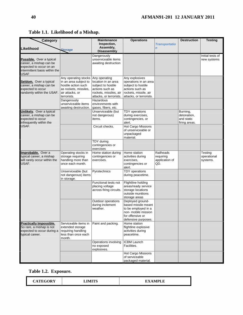
40 AFMAN91-201 12 JANUARY 2011
Table 1.1. Likelihood of a Mishap.
Category Likelihood Storage
Maintenance Inspection, Assembly,
Disassembly
Operations
Transportation
Destruction Testing
Possible. Over a typical career, a mishap can be expected to occur on an intermittent basis within the USAF
Dangerously unserviceable items awaiting destruction
Initial tests of new systems
Seldom. Over a typical career, a mishap can be expected to occur randomly within the USAF.
Any operating stocks in an area subject to hostile action such as rockets, missiles, air attacks, or terrorists.
Any operating location in an area subject to hostile actions such as rockets, missiles, air attacks, or terrorists.
Any explosives operations in an area subject to hostile actions such as rockets, missile, air attacks, or terrorists.
Dangerously unserviceable items awaiting destruction.
Hazardous environments with gases, fibers, etc.
Unlikely. Over a typical career, a mishap can be expected to occur infrequently within the USAF.
Unserviceable (but not dangerous) items.
TDY operations during exercises, contingencies, or alert.
Burning, detonation, and static firing areas.
Circuit checks. Hot Cargo Missions of unserviceable or unpackaged material.
TDY during contingencies or exercises
Improbable. Over a typical career, a mishap will rarely occur within the USAF.
Operating stocks in storage requiring handling more than once each month.
Home station during contingencies or exercises.
Home station activities during exercises, contingencies or alert.
Railheads requiring application of QD.
Testing operational systems.
Unserviceable (but not dangerous) items in storage.
Pyrotechnics TDY operations during peacetime.
Functional tests not placing voltage across firing circuits.
Flightline holding areas/ready service storage locations outside munitions storage areas
Outdoor operations during inclement weather.
Deployed ground-based missile meant to be employed in a non- mobile mission for offensive or defensive purposes.
Practically Impossible. So rare, a mishap is not expected to occur during a typical career.
Serviceable items in extended storage requiring handling less than once each month.
Paint and packing. Home station flightline explosive activities during peacetime.
Operations involving no exposed explosives.
ICBM Launch Facilities.
Hot Cargo Missions of serviceable packaged material.
Table 1.2. Exposure.
CATEGORY LIMITS EXAMPLE
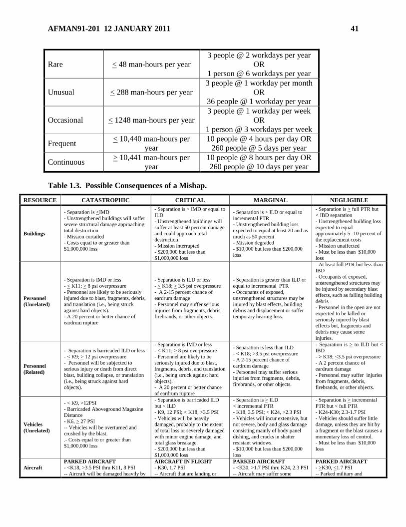
AFMAN91-201 12 JANUARY 2011 41
Rare < 48 man-hours per year
3 people @ 2 workdays per year
OR
1 person @ 6 workdays per year
Unusual < 288 man-hours per year
3 people @ 1 workday per month
OR
36 people @ 1 workday per year
Occasional < 1248 man-hours per year
3 people @ 1 workday per week
OR
1 person @ 3 workdays per week
Frequent < 10,440 man-hours per
year
10 people @ 4 hours per day OR
260 people @ 5 days per year
Continuous > 10,441 man-hours per
year
10 people @ 8 hours per day OR
260 people @ 10 days per year
Table 1.3. Possible Consequences of a Mishap.
RESOURCE CATASTROPHIC CRITICAL MARGINAL NEGLIGIBLE
Buildings
- Separation is <IMD
- Unstrengthened buildings will suffer severe structural damage approaching
total destruction
- Mission curtailed - Costs equal to or greater than
$1,000,000 loss
- Separation is > IMD or equal to ILD
- Unstrengthened buildings will
suffer at least 50 percent damage and could approach total
destruction
- Mission interrupted - $200,000 but less than
$1,000,000 loss
- Separation is > ILD or equal to
incremental PTR - Unstrengthened building loss
expected to equal at least 20 and as
much as 50 percent - Mission degraded
- $10,000 but less than $200,000
loss
- Separation is > full PTR but < IBD separation
- Unstrengthened building loss
expected to equal approximately 5 -10 percent of
the replacement costs
- Mission unaffected - Must be less than $10,000
loss
Personnel
(Unrelated)
- Separation is IMD or less
- < K11; > 8 psi overpressure
- Personnel are likely to be seriously injured due to blast, fragments, debris,
and translation (i.e., being struck
against hard objects). - A 20 percent or better chance of
eardrum rupture
- Separation is ILD or less
- < K18; > 3.5 psi overpressure
- A 2-15 percent chance of eardrum damage
- Personnel may suffer serious
injuries from fragments, debris, firebrands, or other objects.
- Separation is greater than ILD or
equal to incremental PTR
- Occupants of exposed, unstrengthened structures may be
injured by blast effects, building
debris and displacement or suffer temporary hearing loss.
- At least full PTR but less than IBD
- Occupants of exposed,
unstrengthened structures may
be injured by secondary blast
effects, such as falling building
debris - Personnel in the open are not
expected to be killed or
seriously injured by blast effects but, fragments and
debris may cause some
injuries.
Personnel
(Related)
- Separation is barricaded ILD or less
- < K9; > 12 psi overpressure
- Personnel will be subjected to serious injury or death from direct
blast, building collapse, or translation
(i.e., being struck against hard objects).
- Separation is IMD or less - < K11; > 8 psi overpressure
- Personnel are likely to be
seriously injured due to blast, fragments, debris, and translation
(i.e., being struck against hard
objects). - A 20 percent or better chance
of eardrum rupture
- Separation is less than ILD
- < K18; >3.5 psi overpressure - A 2-15 percent chance of
eardrum damage
- Personnel may suffer serious injuries from fragments, debris,
firebrands, or other objects.
- Separation is > to ILD but < IBD
- > K18; <3.5 psi overpressure
- A 2 percent chance of eardrum damage
- Personnel may suffer injuries
from fragments, debris, firebrands, or other objects.
Vehicles
(Unrelated)
- < K9, >12PSI
- Barricaded Aboveground Magazine Distance
- K6, > 27 PSI
-- Vehicles will be overturned and crushed by the blast.
.- Costs equal to or greater than
$1,000,000 loss
- Separation is barricaded ILD
but < ILD
- K9, 12 PSI; < K18, >3.5 PSI
- Vehicles will be heavily damaged, probably to the extent
of total loss or severely damaged
with minor engine damage, and total glass breakage.
- $200,000 but less than
$1,000,000 loss
- Separation is > ILD
< incremental PTR
- K18, 3.5 PSI; < K24, >2.3 PSI
- Vehicles will incur extensive, but not severe, body and glass damage
consisting mainly of body panel
dishing, and cracks in shatter resistant windows.
- $10,000 but less than $200,000
loss
- Separation is > incremental
PTR but < full PTR
- K24-K30; 2.3-1.7 PSI
- Vehicles should suffer little damage, unless they are hit by
a fragment or the blast causes a
momentary loss of control. - Must be less than $10,000
loss
Aircraft
PARKED AIRCRAFT
- <K18, >3.5 PSI thru K11, 8 PSI
-- Aircraft will be damaged heavily by
AIRCRAFT IN FLIGHT
- K30, 1.7 PSI
-- Aircraft that are landing or
PARKED AIRCRAFT
- <K30, >1.7 PSI thru K24, 2.3 PSI
-- Aircraft may suffer some
PARKED AIRCRAFT
- >K30, <1.7 PSI
-- Parked military and
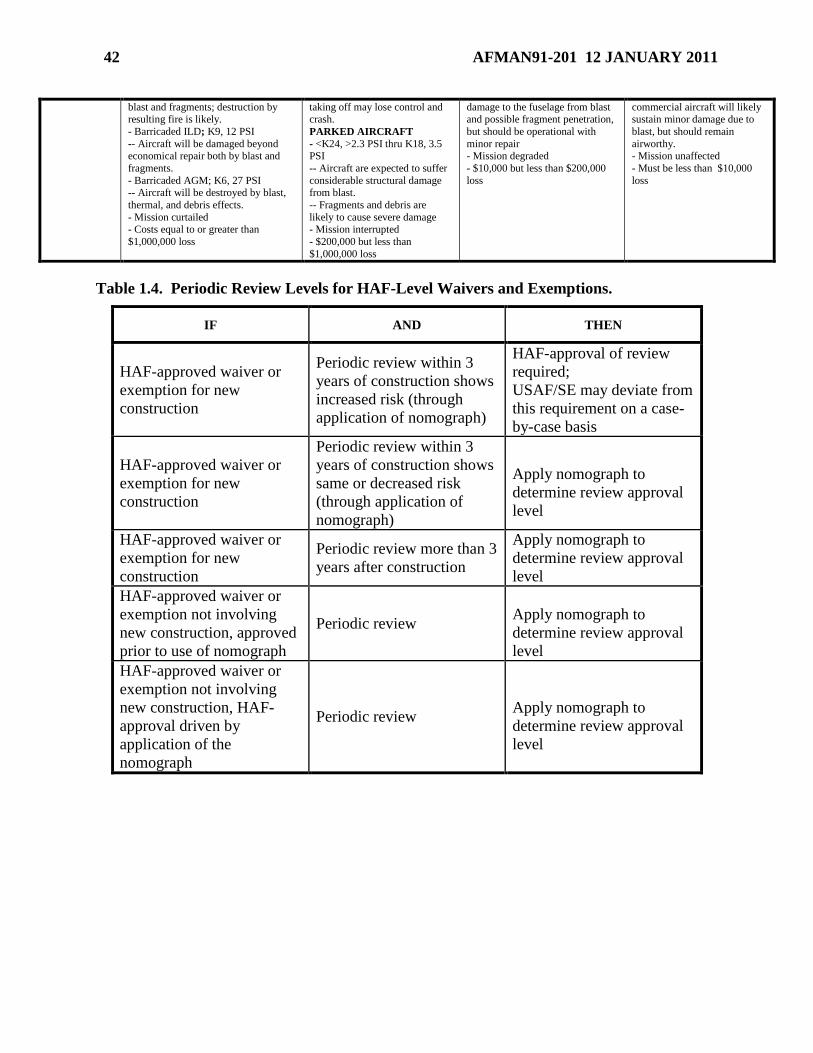
42 AFMAN91-201 12 JANUARY 2011
blast and fragments; destruction by
resulting fire is likely.
- Barricaded ILD; K9, 12 PSI
-- Aircraft will be damaged beyond economical repair both by blast and
fragments.
- Barricaded AGM; K6, 27 PSI -- Aircraft will be destroyed by blast,
thermal, and debris effects.
- Mission curtailed - Costs equal to or greater than
$1,000,000 loss
taking off may lose control and
crash.
PARKED AIRCRAFT
- <K24, >2.3 PSI thru K18, 3.5 PSI
-- Aircraft are expected to suffer
considerable structural damage from blast.
-- Fragments and debris are
likely to cause severe damage - Mission interrupted
- $200,000 but less than
$1,000,000 loss
damage to the fuselage from blast
and possible fragment penetration,
but should be operational with
minor repair - Mission degraded
- $10,000 but less than $200,000
loss
commercial aircraft will likely
sustain minor damage due to
blast, but should remain
airworthy. - Mission unaffected
- Must be less than $10,000
loss
Table 1.4. Periodic Review Levels for HAF-Level Waivers and Exemptions.
IF AND THEN
HAF-approved waiver or
exemption for new
construction
Periodic review within 3
years of construction shows
increased risk (through
application of nomograph)
HAF-approval of review
required;
USAF/SE may deviate from
this requirement on a case-
by-case basis
HAF-approved waiver or
exemption for new
construction
Periodic review within 3
years of construction shows
same or decreased risk
(through application of
nomograph)
Apply nomograph to
determine review approval
level
HAF-approved waiver or
exemption for new
construction
Periodic review more than 3
years after construction
Apply nomograph to
determine review approval
level
HAF-approved waiver or
exemption not involving
new construction, approved
prior to use of nomograph
Periodic review
Apply nomograph to
determine review approval
level
HAF-approved waiver or
exemption not involving
new construction, HAF-
approval driven by
application of the
nomograph
Periodic review
Apply nomograph to
determine review approval
level
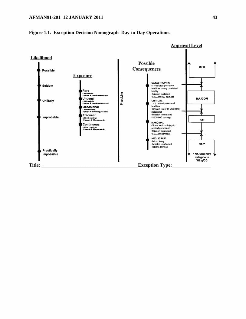
AFMAN91-201 12 JANUARY 2011 43
Figure 1.1. Exception Decision Nomograph–Day-to-Day Operations.
Title: ________________________________________Exception Type:________________
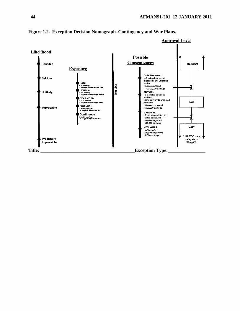
44 AFMAN91-201 12 JANUARY 2011
Figure 1.2. Exception Decision Nomograph–Contingency and War Plans.
Title: ________________________________________Exception Type:________________
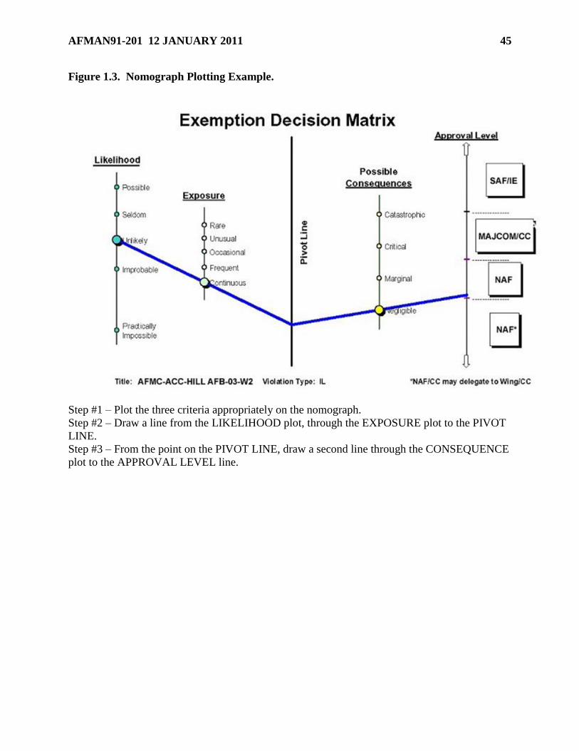
AFMAN91-201 12 JANUARY 2011 45
Figure 1.3. Nomograph Plotting Example.
Step #1 – Plot the three criteria appropriately on the nomograph.
Step #2 – Draw a line from the LIKELIHOOD plot, through the EXPOSURE plot to the PIVOT
LINE.
Step #3 – From the point on the PIVOT LINE, draw a second line through the CONSEQUENCE
plot to the APPROVAL LEVEL line.
46 AFMAN91-201 12 JANUARY 2011
Chapter 2
REACTION EFFECTS
Section 2A—Principal Effects of High Density (HD) 1.1 Events
2.1. Blast.
2.1.1. Blast Wave Phenomena. In an incident involving HD 1.1, or HD 1.1 with any other
HD (a HD 1.1 event), the violent release of energy creates a sudden and intense pressure
disturbance termed the ―blast wave.‖ The blast wave is characterized by an almost
instantaneous rise from ambient pressure to a peak incident pressure (Pi). This pressure
increase, or ―shock front,‖ travels radially outward from the detonation point, with a
diminishing velocity that is always in excess of the speed of sound in that medium. Gas
molecules making up the front move at lower velocities. This velocity, which is called the
―particle velocity,‖ is associated with the ―dynamic pressure,‖ or the pressure formed by the
winds produced by the shock front.
2.1.1.1. As the shock front expands into increasingly larger volumes of the medium, the
incident pressure decreases and, generally, the duration of the pressure-pulse increases.
2.1.1.2. If the shock wave impinges a rigid surface (e.g., a building) at an angle to the
direction of the wave’s propagation, a reflected pressure is instantly developed on the
surface and this pressure rises to a value that exceeds the incident pressure. This
reflected pressure is a function of the incident wave’s pressure and the angle formed
between the rigid surface and the plane of the shock front.
2.1.2. Partially Confined Explosions. When an explosion occurs within a structure, the
peak pressure associated with the initial shock front will both be high and amplified by
reflections within the structure. In addition, the accumulation of gases from the explosion
will exert additional pressure and increase the load duration within the structure. This effect
may damage or destroy the structure unless the structure is designed to either withstand or
vent the gas and shock pressures. Structures that have one or more strengthened walls may
be vented for relief of excessive gas by either frangible construction of the remaining walls
or roof or through the use of openings. This type of construction will permit the gas from an
internal explosion to spill out of the structure. Once released from confinement, these
pressures (referred to as ―exterior‖ or ―leakage‖ pressures) expand radially and may affect
external structures or personnel.
2.1.3. QD K-factors. Throughout this Manual, NEWQD is used to calculate QD
separations for blast protection by means of a formula using a ―K-factor.‖ See paragraph
12.11. for explanation of this formula.
2.1.4. Expected Blast Pressures at QD Table 2.1 presents the incident pressures that would
be expected at various K-factors from HD 1.1 events. Use of the Incident Airblast Calculator
and the Blast Effects Calculator (BEC) may also be used.
2.1.5. General Blast Effects On Structures.
AFMAN91-201 12 JANUARY 2011 47
2.1.5.1. Conventional Structures. Conventional structures are generally designed to
withstand roof-snow loads of 0-50 pounds per square foot or wind loads up to 90 miles
per hour, or both. At 90 mph, the wind load equates to 0.14 psi. Given the pressures
shown in Table 2.1 for the selected K-factors, it is evident that, even at inhabited building
distance (IBD), conventional structures may not provide complete protection from blast.
Generally, the weakest portions of any conventional structure are the windows. Table 2.2
provides the probability of breaking typical windows at various K-factors and associated
incident pressures from HD 1.1 events.
2.1.5.2. Above Ground Structures (AGS). These are generally considered
conventional structures and provide little protection from blast or fragmentation. (See
paragraph 2.5.)
2.1.5.3. Earth-Covered Magazine (ECM). An explosion at an ECM produces high
reflected pressure and impulse. These can damage doors and headwalls of adjacent
ECMs, propelling debris onto contents and communicating the explosion. When
separated from each other by the minimum distances required by Table 12.1, ECMs (see
Section 6C) provide AE with virtually complete protection against
propagation. However, AE in adjacent ECMs may be damaged and structural damage
ranging from cracks in concrete, damage to ventilators and doors to complete structural
failure may occur in the corresponding ECM. (NOTE:When ECMs containing HD 1.1
AE are sited so that if any one is in the forward sector of another, the two must be
separated by distances greater than the minimum permitted for side-to-side
orientations. The greater distances are required to protect the door and headwall of a
facing ECM from the adjacent explosion; to a lesser extent, they are required as
protection from the directional effects of the source.)
2.1.5.4. Underground Storage Facilities. Underground facilities sited per DoD
6055.09-M, Volume 5, DoD Ammunition and Explosives Safety Standards provide a high
degree of protection against propagation of an explosion between chambers, and between
underground and aboveground structures. An HD 1.1 explosion in an underground
storage facility causes very high pressures of prolonged duration. Blast waves and the
accompanying gas flows will travel throughout the underground facility at high velocity.
2.1.5.5. Barricaded Open-Storage Modules. Barricaded open-storage modules (see
Section 6D) provide a high degree of protection against the propagation of an
explosion. However, if flammable materials are present in nearby cells, subsequent
propagation by fire is possible. When an explosion occurs in adjacent modules separated
by K1.1, AE will be thrown tens of meters and be covered with earth, thereby unavailable
for use until extensive uncovering operations, and possibly maintenance, are
completed. Items at K=2.5 separation distance from a donor explosion are expected to be
readily accessible.
2.1.6. General Blast Effects on Personnel. Tables 2.3, 2.4 and 2.5 describe the expected
effects of blast on personnel.
2.1.7. Computation of Blast Effects. Many of the blast effects described in this section
were computed using the DDESB Blast Effects Computer (available at
http://www.ddesb.pentagon.mil) and proven test methodologies as outlined in Department
of Defense Explosives Safety Board (DDESB) Technical Paper (TP) 16, Current revision,
48 AFMAN91-201 12 JANUARY 2011
Methodologies for Calculating Primary Fragment Characteristics. The DDESB Blast
Effects Computer can be used to estimate similar effects associated with various NEWQDs,
facilities, and distances.
2.2. Fragments. General. An important consideration in the analysis of the hazards associated
with an explosion is the effect of any fragments produced. Although most common in HD 1.1 or
HD 1.2 (see Section 2B) events, fragmentation may occur in any incident involving
AE. Depending on their origin, fragments are referred to as ―primary‖ or ―secondary‖
fragments.
2.2.1. Primary fragments result from the shattering of a container (e.g., shell casings, kettles,
hoppers, and other containers used in the manufacture of explosives, rocket engine housings)
in direct contact with the explosive. These fragments usually are small, initially travel at
thousands of feet per second and may be lethal at long distances from an explosion.
2.2.2. Secondary fragments are debris from structures and other items in close proximity to
the explosion. These fragments, which are somewhat larger in size than primary fragments
and initially travel at hundreds of feet per second, do not normally travel as far as primary
fragments.
2.2.3. The earth cover of an underground facility may rupture and create a significant debris
hazard.
2.2.4. A hazardous fragment is one having an impact energy of 58 ft-lb or greater.
2.2.5. A hazardous fragment density is 1 hazardous fragment per 600 ft2.
2.3. Thermal Hazards.
2.3.1. General. Generally, thermal hazards from a HD 1.1 event are less hazardous than
blast and fragment hazards.
2.3.2. Personnel. It normally takes longer to incur injury from thermal effects than from
either blast or fragmentation effects because both blast and fragmentation occur almost
instantaneously. The time available to react to a thermal event increases survivability.
2.3.3. Structures, Material, and AE. The primary thermal effect on structures, material,
and AE is their partial or total destruction by fire. The primary concern with a fire involving
AE is that it may transition to a more severe reaction, such as a detonation.
2.4. Groundshock and Cratering.
2.4.1. General.
2.4.1.1. In an airburst, there may be a downward propagation of ground shock. Cratering
may be reduced or eliminated.
2.4.1.2. In a surface burst, ground shock is generated and cratering can be significant.
2.4.1.3. A buried or partially buried detonation produces the strongest ground shock;
however, if the explosion is deep enough, no crater will be formed.
2.4.2. Underground Facilities. AE protection can be achieved by proper chamber spacing.
An HD 1.1 explosion will produce ground shocks that may rupture the earth cover and eject
debris. (See DoD 6055.09-M.)
AFMAN91-201 12 JANUARY 2011 49
2.5. Expected Consequences.
2.5.1. Barricaded Aboveground Magazine Distance – K6 (27 psi). At this distance:
2.5.1.1. Unstrengthened buildings will be destroyed.
2.5.1.2. Personnel will be killed by blast, by being struck by debris, or by impact against
hard surfaces.
2.5.1.3. Transport vehicles will be overturned and crushed by the blast.
2.5.1.4. Explosives-loaded vessels will be damaged severely, with propagation of
explosion likely.
2.5.1.5. Aircraft will be destroyed by blast, thermal, and debris effects.
2.5.1.6. Barricades are an effective control measure for preventing immediate
propagation of explosion by high velocity low angle fragments. However, they provide
only limited protection against any delayed propagation of explosives caused by a fire
resulting from high angle firebrands.
2.5.2. Barricaded Intraline Distance – K9 (12 psi). At this distance:
2.5.2.1. Unstrengthened buildings will suffer severe structural damage approaching total
destruction.
2.5.2.2. Personnel will be subject to severe injuries or death from direct blast, building
collapse, or translation.
2.5.2.3. Aircraft will be damaged beyond economical repair both by blast and fragments.
(If the aircraft are loaded with explosives, delayed explosions are likely to result from
subsequent fires.)
2.5.2.4. Transport vehicles will be damaged heavily, probably to the extent of total loss.
2.5.2.5. Improperly designed barricades or structures may increase the hazard from
flying debris, or may collapse in such a manner as to increase the risk to personnel and
equipment.
2.5.2.6. Barricading is a required control measure. Direct propagation of explosion
between two explosive locations is unlikely when barricades are placed between them to
intercept high velocity low angle fragments. Exposed structures containing high value,
mission critical equipment or personnel may require hardening.
2.5.3. Unbarricaded Aboveground Magazine Distance – K11 (8 psi). At this distance:
2.5.3.1. Unstrengthened buildings will suffer damage approaching total destruction.
2.5.3.2. Personnel are likely to be injured seriously due to blast, fragments, debris, and
translation.
2.5.3.3. There is a 15 percent risk of eardrum rupture.
2.5.3.4. Explosives-loaded vessels are likely to be damaged extensively and delayed
propagation of explosion may occur.
2.5.3.5. Aircraft will be damaged heavily by blast and fragments; destruction by
resulting fire is likely.
50 AFMAN91-201 12 JANUARY 2011
2.5.3.6. Transport vehicles will sustain severe body damage, minor engine damage, and
total glass breakage.
2.5.3.7. As a control, barricading will significantly reduce the risk of propagation of
explosion and injury of personnel by high velocity low angle fragments.
2.5.4. Unbarricaded Intraline Distance – K18 (3.5 psi). At this distance:
2.5.4.1. Direct propagation of explosion is not expected.
2.5.4.2. Delayed propagation of an explosion may occur at the ES, as either a direct
result of a fire or as a result of equipment failure.
2.5.4.3. Damage to unstrengthened buildings may approximate 50 percent, or more, of
the total replacement cost. Sensitive electronic equipment is expected to stop
functioning.
2.5.4.4. There is a two percent chance of eardrum damage to personnel.
2.5.4.5. Personnel may suffer serious injuries from fragments, debris, firebrands, or other
objects.
2.5.4.6. Fragments could damage the decks and superstructure of cargo ships and
overpressure could buckle their doors and bulkheads on weather decks.
2.5.4.7. Aircraft can be expected to suffer considerable structural damage from blast.
Fragments and debris are likely to cause severe damage to aircraft at K18 distances when
small quantities of explosives are involved.
2.5.4.8. Transport vehicles will incur extensive, but not severe, body and glass damage
consisting mainly of dishing of body panels and cracks in shatter-resistant window glass.
2.5.4.9. Suitably designed suppressive construction at PES or protective construction at
ES may be practical controls for some situations. Such construction is encouraged when
there is insufficient distance to provide the required protection.
2.5.5. Public Traffic Route Distance (PTRD) (under 100,000 lbs HE) – K24 (2.3 psi). At
this distance:
2.5.5.1. Unstrengthened buildings can be expected to sustain damage approximately 20
percent of the replacement cost.
2.5.5.2. Occupants of exposed structures may suffer temporary hearing loss or injury
from blast effects, building debris and displacement.
2.5.5.3. Although personnel in the open are not expected to be killed or seriously injured
by blast effects, fragments and debris may cause some injuries. The extent of these
injuries depends largely upon the PES structure and the amount and fragmentation
characteristics of the AE involved.
2.5.5.4. Vehicles on the road should suffer little damage, unless they are hit by a
fragment or the blast causes a momentary loss of control.
2.5.5.5. Aircraft may suffer some damage to the fuselage from blast and possible
fragment penetration, but should be operational with minor repair.
AFMAN91-201 12 JANUARY 2011 51
2.5.5.6. Cargo-type ships should suffer minor damage to deck structure and exposed
electronics from blast and possible fragment penetration, but such damage should be
readily repairable.
2.5.5.7. Barricading is an effective control that can reduce the risk of injury or damage
due to fragments for limited quantities of AE at a PES. When practical, suitably designed
suppressive construction at the PES or protective construction at the ES may also provide
some protection.
2.5.6. Public Traffic Route Distance (over 250,000 lbs HE) – K30 (1.7 psi). At this distance:
2.5.6.1. Unstrengthened buildings can be expected to sustain damage that may
approximate 10 percent of their replacement cost.
2.5.6.2. Occupants of exposed, unstrengthened structures may be injured by secondary
blast effects, such as falling building debris.
2.5.6.3. Pilots of aircraft that are landing or taking off may lose control and crash.
2.5.6.4. Parked military and commercial aircraft will likely sustain minor damage due to
blast, but should remain airworthy.
2.5.6.5. Although personnel in the open are not expected to be killed or seriously injured
by blast effects, fragments and debris may cause some injuries. The extent of these
injuries will largely depend upon the PES structure, the NEWQD, and the fragmentation
characteristics of the AE involved.
2.5.6.6. Barricading or the application of minimum fragmentation distance requirements
are effective controls that may reduce the risk of injury or damage due to fragments for
limited quantities of AE at a PES.
2.5.7. Inhabited Building Distance (IBD) – K40 to K50 (1.2 psi to 0.90 psi). At this
distance:
2.5.7.1. Unstrengthened buildings can be expected to sustain damage that approximates
five percent of their replacement cost.
2.5.7.2. Personnel in buildings are provided a high degree of protection from death or
serious injury; however, glass breakage and building debris may still cause some injuries.
2.5.7.3. Personnel in the open are not expected to be injured seriously by blast effects.
Fragments and debris may cause some injuries. The extent of injuries will depend upon
the PES structure and the NEWQD and fragmentation characteristics of the AE involved.
2.5.7.4. Elimination of glass surfaces is the best control. If determined to be
necessary, reducing the use of glass or the size of any glass surfaces and the use of
blast resistant glass will provide some relief. For new construction, building design
characteristics, to include consideration of how any required glass surfaces are
oriented and use of blast resistant glass, can reduce glass breakage and structural
damage.
Section 2B—Principal Effects of HD 1.2 Events.
2.6. Blast.
52 AFMAN91-201 12 JANUARY 2011
2.6.1. HD 1.2, when not stored with HD 1.1 or HD 1.5, is not expected to mass detonate. In
an incident involving HD 1.2, when stored by itself or with HD 1.3, HD 1.4, or HD 1.6 (a
HD 1.2 event), AE can be expected to both explode sporadically and burn. Fire will
propagate through the mass of the AE over time. Some AE may neither explode nor burn.
Blast effects from the incident are limited to the immediate vicinity and are not considered to
be a significant hazard.
2.6.2. A HD 1.2 event may occur over a prolonged period of time. Generally, the first
reactions are relatively nonviolent and, typically, begin a few minutes after flames engulf the
AE. Later reactions tend to be more violent. Reactions can continue for some time (hours),
even after a fire is effectively out. Generally, smaller AE tends to react earlier in an incident
than larger AE.
2.6.3. The results of an accidental explosion in an underground facility will depend on the
type and quantity of munitions, the type of explosion produced, and the layout of the facility.
Hazards created outside the underground facility will likely not be as severe as those
produced by HD 1.1 or 1.3 material.
2.7. Fragments.
2.7.1. The primary hazard from a HD 1.2 event is fragmentation. Fragmentation may
include primary fragments from AE casings or secondary fragments from containers and
structures. At longer ranges, primary fragments are the major contributors to fragment
hazards.
2.7.2. During a HD 1.2 event, fragmentation may extensively damage exposed facilities.
However, less fragmentation damage can be expected from a given quantity of HD 1.2 than
would be expected from the corresponding quantity of HD 1.1 because not all the HD 1.2
will react.
2.8. Thermal Hazards.
2.8.1. An incident involving a quantity of HD 1.2 poses considerably less thermal risk to
personnel than an incident involving corresponding quantities of either HD 1.1 or HD 1.3
because a HD 1.2 event’s progressive nature allows personnel to immediately evacuate the
area.
2.8.2. A HD 1.2 event’s progressive nature provides an opportunity for a fire suppression
system, if installed, to put out a fire in its early stages.
2.9. Ejected Items. In HD 1.2 events, a reaction may eject (lob) unreacted-AE or AE
components from the event site. These ejected items may subsequently react.
2.10. Propelled Items. In HD 1.2 events, some AE or AE components may become propulsive
and travel well beyond IBD.
2.11. Firebrands. In an incident involving only HD 1.2 or HD 1.2 with HD 1.4, firebrands are
considered to be a hazard only in the immediate vicinity of the incident site.
2.12. Expected Consequences.
2.12.1. The expected consequences for HD 1.2 AE are similar to those for HD 1.1. The
effects of HD 1.2 AE are NEWQD dependent.
AFMAN91-201 12 JANUARY 2011 53
2.12.2. The principal hazard to personnel in the open, to aircraft, and to occupied vehicles is
fragments.
2.12.3. Airblast, fragment, and thermal hazards to buildings and parked aircraft or vehicles
cannot be predicted reliably because the effects will depend on the maximum credible event
(MCE).
Section 2C—Principal Effects of HD 1.3 Events
2.13. Gas Pressures. In an incident involving only HD 1.3 or HD 1.3 with HD 1.4 (a HD 1.3
event):
2.13.1. Where sufficient venting is provided, gas pressures generated by the event are not a
significant concern. Examples of sites with sufficient venting include open storage and
structures where internal pressures do not exceed 1 to 2 psi (non-confinement structure).
2.13.2. Where venting is insufficient, internal gas pressures may be substantial. In such
situations, these pressures may blow out vent panels or frangible walls and, in some
instances, cause partial or complete structural failure.
2.13.3. Where there is minimal venting and structural containment (extreme confinement), a
detonation of the HD 1.3 may occur with effects similar to those of a HD 1.1 explosion. For
example, HD 1.3 AE is considered as HD 1.1 (mass explosion) for QD purposes when stored
in underground chambers.
2.14. Fragments. In a HD 1.3 event, fragments are considerably less hazardous than those
produced by HD 1.1 and HD 1.2 events. Internal gas pressures may produce fragments from the
bursting of containers or the rupture of containment facilities. In general, such fragments will be
large and of low velocity. (For exceptions, see paragraph 2.13.3.)
2.15. Thermal Hazards. In a HD 1.3 event, heat flux presents the greatest hazard to personnel
and assets. HD 1.3 substances include both fuel components and oxidizers. Burning HD 1.3
emits fuel-rich flammable gases, fine particles, or both. This unburned material may ignite when
it comes in contact with air and cause a large fireball. This fireball will expand radially from the
ignition site and could wrap around obstacles, even those designed to provide line-of-sight
protection from HD 1.1 events. Shields and walls can be designed to provide protection from
thermal effects (see Chapter 4).
2.15.1. The nominal spherical fireball that would be expected from the rapid burning of HD
1.3 can be calculated by DFIRE = 10 x WEFF1/3
where DFIRE is the diameter of the fireball (ft)
and WEFF is the quantity of HD 1.3 involved (lb), multiplied by a 20% safety factor (e.g., W
of 100 pounds = WEFF of 120 pounds).
2.15.2. In addition to the fireball itself, the thermal flux from the fireball can ignite fires out
to intermagazine distance (IMD).
2.16. Propelled Items. In a HD 1.3 event, some AE or AE components may become propulsive
and travel well beyond IBD.
2.17. Firebrands. In a HD 1.3 event, a severe fire-spread hazard may result from firebrands
projected from the incident site. Firebrands can be expected to be thrown more than 50 ft from a
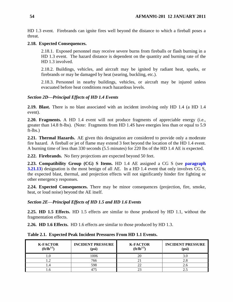
54 AFMAN91-201 12 JANUARY 2011
HD 1.3 event. Firebrands can ignite fires well beyond the distance to which a fireball poses a
threat.
2.18. Expected Consequences.
2.18.1. Exposed personnel may receive severe burns from fireballs or flash burning in a
HD 1.3 event. The hazard distance is dependent on the quantity and burning rate of the
HD 1.3 involved.
2.18.2. Buildings, vehicles, and aircraft may be ignited by radiant heat, sparks, or
firebrands or may be damaged by heat (searing, buckling, etc.).
2.18.3. Personnel in nearby buildings, vehicles, or aircraft may be injured unless
evacuated before heat conditions reach hazardous levels.
Section 2D—Principal Effects of HD 1.4 Events
2.19. Blast. There is no blast associated with an incident involving only HD 1.4 (a HD 1.4
event).
2.20. Fragments. A HD 1.4 event will not produce fragments of appreciable energy (i.e.,
greater than 14.8 ft-lbs). (Note: Fragments from HD 1.4S have energies less than or equal to 5.9
ft-lbs.)
2.21. Thermal Hazards. AE given this designation are considered to provide only a moderate
fire hazard. A fireball or jet of flame may extend 3 feet beyond the location of the HD 1.4 event.
A burning time of less than 330 seconds (5.5 minutes) for 220 lbs of the HD 1.4 AE is expected.
2.22. Firebrands. No fiery projections are expected beyond 50 feet.
2.23. Compatibility Group (CG) S Items. HD 1.4 AE assigned a CG S (see paragraph
3.21.13) designation is the most benign of all AE. In a HD 1.4 event that only involves CG S,
the expected blast, thermal, and projection effects will not significantly hinder fire fighting or
other emergency responses.
2.24. Expected Consequences. There may be minor consequences (projection, fire, smoke,
heat, or loud noise) beyond the AE itself.
Section 2E—Principal Effects of HD 1.5 and HD 1.6 Events
2.25. HD 1.5 Effects. HD 1.5 effects are similar to those produced by HD 1.1, without the
fragmentation effects.
2.26. HD 1.6 Effects. HD 1.6 effects are similar to those produced by HD 1.3.
Table 2.1. Expected Peak Incident Pressures From HD 1.1 Events.
K-FACTOR
(ft/lb1/3
)
INCIDENT PRESSURE
(psi)
K-FACTOR
(ft/lb1/3
)
INCIDENT PRESSURE
(psi)
1.0 1006 20 3.0
1.2 766 21 2.8
1.4 598 22 2.6
1.6 475 23 2.5
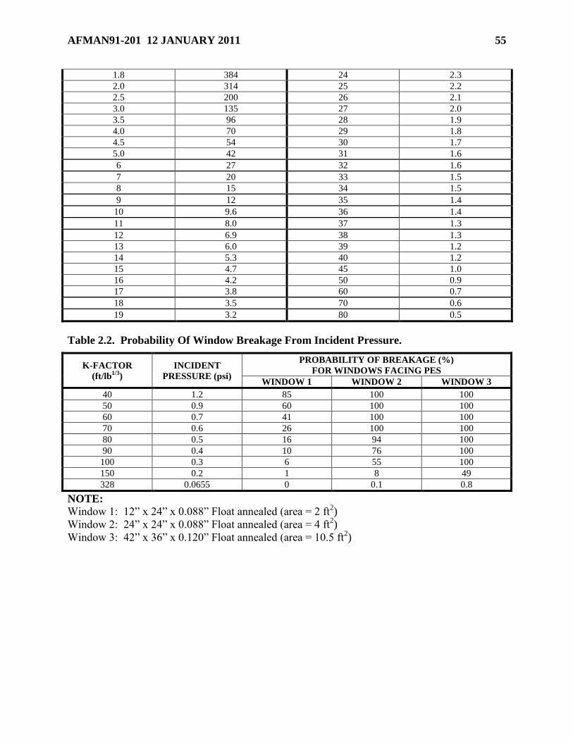
AFMAN91-201 12 JANUARY 2011 55
1.8 384 24 2.3
2.0 314 25 2.2
2.5 200 26 2.1
3.0 135 27 2.0
3.5 96 28 1.9
4.0 70 29 1.8
4.5 54 30 1.7
5.0 42 31 1.6
6 27 32 1.6
7 20 33 1.5
8 15 34 1.5
9 12 35 1.4
10 9.6 36 1.4
11 8.0 37 1.3
12 6.9 38 1.3
13 6.0 39 1.2
14 5.3 40 1.2
15 4.7 45 1.0
16 4.2 50 0.9
17 3.8 60 0.7
18 3.5 70 0.6
19 3.2 80 0.5
Table 2.2. Probability Of Window Breakage From Incident Pressure.
K-FACTOR
(ft/lb1/3
)
INCIDENT
PRESSURE (psi)
PROBABILITY OF BREAKAGE (%)
FOR WINDOWS FACING PES
WINDOW 1 WINDOW 2 WINDOW 3
40 1.2 85 100 100
50 0.9 60 100 100
60 0.7 41 100 100
70 0.6 26 100 100
80 0.5 16 94 100
90 0.4 10 76 100
100 0.3 6 55 100
150 0.2 1 8 49
328 0.0655 0 0.1 0.8
NOTE:
Window 1: 12‖ x 24‖ x 0.088‖ Float annealed (area = 2 ft2)
Window 2: 24‖ x 24‖ x 0.088‖ Float annealed (area = 4 ft2)
Window 3: 42‖ x 36‖ x 0.120‖ Float annealed (area = 10.5 ft2)
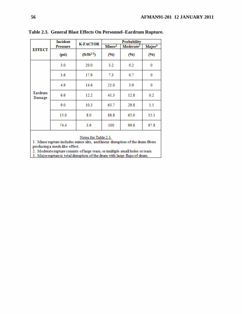
56 AFMAN91-201 12 JANUARY 2011
Table 2.3. General Blast Effects On Personnel–Eardrum Rupture.
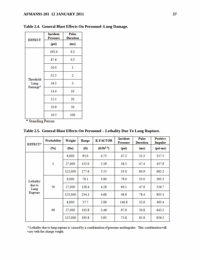
AFMAN91-201 12 JANUARY 2011 57
Table 2.4. General Blast Effects On Personnel–Lung Damage.
Table 2.5. General Blast Effects On Personnel – Lethality Due To Lung Rupture.
58 AFMAN91-201 12 JANUARY 2011
Chapter 3
HAZARD CLASSIFICATION
Section 3A—DoD Hazard Classification System
3.1. Purpose of Hazard Classification. The DoD Hazard Classification System is designed to
reflect the type and degree of hazard associated with an AE item. It is used to determine the
degree of protection (such as distance separation) needed for various exposed locations and
people, and to determine which items can be safely stored together. Each AE item is assigned a
hazard classification based on the form in which it is normally available as well as its common
packaging, storage and transportation (commercial or military) configurations.
3.2. Responsibility for Hazard Classification. Air Force organizations that develop or are the
first to adopt AE items for use are responsible for obtaining DoD hazard classifications using the
procedures in Technical Order (T.O.) 11A-1-47, DoD Ammunition and Explosives Hazard
Classification Procedures. It is the program office’s responsibility to ensure AE items are
properly hazard classified before they enter Air Force installations.
3.3. Hazard Classification Authorities. The Air Force hazard classification authorities are
AFSC/SEW, AAC/SES, and 784 CBSG. Army and Navy hazard classification authorities are
listed in T.O. 11A-1-47.
3.4. Standards for Determining DoD Hazard Classification. Use the following resources to
identify AE hazard characteristics for storage and transportation purposes:
3.4.1. T.O. 11A-1-47, as a basis for assigning hazard classifications to all AE for both
storage and transportation applications.
3.4.2. The applicable Department of Transportation (DOT) hazardous materials regulations
per 49 CFR 171 to 177.
3.4.3. The United Nations’ (UN) international system of classification developed for the
transport of dangerous goods, ST/SG/AC.10/1/latest revision, Recommendations on the
Transport of Dangerous Goods.
3.5. Description of DoD Hazard Classification System. The DoD hazard classification system
consists of nine hazard classes plus a Not-Regulated category, thirteen compatibility groups, five
sensitivity groups, and a parenthetical number.
3.5.1. Hazard Classes.
3.5.1.1. Class 1. AE is assigned to the class that represents an item’s predominant
hazard characteristic. Class 1 applies to AE in which the explosive hazard predominates.
The six Class 1 divisions used to indicate the character and predominance of explosive
hazards. This Manual uses the term ―Hazard Division (HD)‖ to avoid repeatedly using
the more cumbersome terminology ―Subdivision X of Division Y of Class Z.‖ The Class
1 divisions and subdivisions are described in Section 3D. See Chapter 2 for detailed
reaction effects of Class 1 AE.
3.5.1.2. Classes 2 through 9. The DoD inventory includes AE items assigned to Class 2
(compressed gas), Class 3 (flammable liquid), Class 4.1 (flammable solid), Class 5.1
AFMAN91-201 12 JANUARY 2011 59
(oxidizer), Class 6.1 (poisonous materials), and Class 8 (corrosive materials). Although
these items contain a small amount of explosives, the predominant hazard is not an
explosive reaction. They are assigned to Classes 2 through 9 based on the predominant
hazard. The DoD hazard classification system classifies articles that contain riot control
substances, without explosives components, and bulk toxic chemical agents as HD
6.1. Any item that contains explosives, but is not assigned to Class 1 due to its
predominant hazard, is considered to have a net explosive weight of zero for QD
determinations. Items that fall into this category do not contribute to the net explosive
weight calculated for the storage site. Even though such items are assigned to another
class, they will still have a DoD storage compatibility group designation, and may be
combined in storage with compatible Class 1 items. When Classes 2 through 9
ammunition items are stored alone, they do not require siting or licensing, except as an
exposed site.
3.5.1.3. Not-Regulated Category. This category applies when explosives and
hazardous materials are present in an item, but not to the degree that criteria for
assignment to one of the nine classes are met. Items that contain a hazardous material,
but that have been designated Not-Regulated, do not require storage or handling as a
hazardous material. The explosive weight of Not-Regulated items is not considered for
QD purposes.
3.5.2. Compatibility Groups. Compatibility Groups (CG) are used for segregating AE on
the basis of similarity of function, features, and accident effects potential. In developing the
various compatibility groups, these factors are considered: chemical and physical properties,
design characteristics, inner and outer packaging configurations, hazard class and division,
NEWQD, rate of deterioration, sensitivity to initiation, and effects of deflagration, explosion,
or detonation. The compatibility groups are described in Section 3E.
3.5.3. Sensitivity Groups. Sensitivity Groups (SG) are used for determining allowable net
explosive weights where ARMCO Revetments or substantial dividing walls are used. The
sensitivity groups are described in Section 3E.
3.5.4. Parenthetical Number. A parenthetical number is used to indicate the minimum
separation distance (in hundreds of feet) for protection from debris, fragments, and firebrands
when distance alone is relied on for such protection. This number is placed to the left of the
hazard classification designators (e.g., (12)1.1, (08)1.2.3, or (02)1.3). It is assigned for all
HD 1.2.3 items, and some HD 1.1 and 1.3 items.
3.6. Net Explosive Weight and Net Explosive Weight for Quantity-Distance. The Net
Explosives Weight (NEW) listed in DoD Joint Hazard Classification System (JHCS) is the total
weight of all explosive, propellant, and pyrotechnic material in a single article. The NEW is
identified because transportation regulations require documentation of the NEW on shipping
papers for transportation. However, the NEWQD is used for explosives siting. The NEWQD is
equal to the NEW unless hazard classification testing has shown that a lower weight is
appropriate for QD purposes. If the NEWQD is less than the NEW, the reason is usually that
propellant or other substances do not contribute as much to the blast effect as the same amount of
high explosives would.
3.7. Requirement for DoD Hazard Classification. Except as allowed in Section 3B, DoD
hazard classifications are required as follows:
60 AFMAN91-201 12 JANUARY 2011
3.7.1. Interim hazard classification must be assigned to explosives items under development,
test articles, components, and certain explosive commercial products having no final hazard
classification if they are to be stored on DoD property or transported. DoD hazard
classification authorities document the interim classification in letters. These letters must be
included in storage and shipment documentation until the classification is finalized. The
agency obtaining the interim hazard classification must renew it upon termination (as
specified in the letter). This applies if the item is still in the inventory or until final hazard
classification is determined. Interim DoD hazard classifications assigned by Army and Navy
classification authorities are acceptable to the Air Force.
3.7.2. A final hazard classification must be assigned for explosives items that have become
operationally fielded and items requiring commercial shipping outside CONUS. DoD final
hazard classifications are listed in the JHCS. Access to the JHCS can be made through the
Defense Ammunition Center at https://www3.dac.army.mil/. Final DoD hazard
classifications assigned by Army and Navy hazard classification authorities are acceptable to
the Air Force.
Section 3B—Storage and Transportation Without DoD Hazard Classification
3.8. Storage and Transportation Without DoD Hazard Classification. Occasionally it will
be necessary to store or transport explosive substances or articles that do not have DoD-assigned
final or interim hazard classifications. Since such items are not listed in the JHCS, the unit
having custody of these items must exercise care in maintaining appropriate approval and hazard
classification documentation at the storage installation. Such documentation may include
Department of Energy (DOE) interim hazard classifications, DOT EX-numbers, or locally-
assigned storage hazard classifications established in accordance with procedures approved by
the AFSC. Paragraphs 3.9, 3.10, 3.11, 3.12, 3.13 describe the circumstances and the respective
applicable conditions for storing or transporting AE without DoD hazard classification.
3.9. Explosives With DOE Hazard Classifications.
3.9.1. An item covered by a DOE interim hazard classification may be stored and offered for
military or commercial transportation using that classification, subject to the requirements of
paragraph 3.9.3. A copy of the applicable DOE interim hazard classification must be
maintained at the installation where the items are stored, and must be carried with shipping
papers on board each conveyance being used to transport the items under that interim hazard
classification.
3.9.2. An item covered by a DOE final hazard classification may be stored and offered for
military or commercial transportation using that classification, subject to the requirements of
paragraph 3.9.3. For storage using DOE final hazard classifications, installation records
must reflect the DOT EX-number, Class, Division, Compatibility Group, and NEW for each
item stored.
3.9.3. Restrictions on the use of DOE hazard classifications:
3.9.3.1. Treat DOE assigned HD 1.2 as HD 1.2.1 and DOE assigned HD 1.5 as HD 1.1
unless an Air Force hazard classification authority (see paragraph 3.3) determines a
different hazard classification applies.
3.9.3.2. Use the compatibility group assigned by DOE.
AFMAN91-201 12 JANUARY 2011 61
3.9.3.3. The NEWQD will equal the NEW. For quantity-distance purposes, the
NEWQD of articles hazard classified by DOE as HD 1.4S or as Not-Regulated will equal
zero. See paragraph 3.16.4 for MCE for HD 1.2.1.
3.9.3.4. Items must be stored or transported in the same or equivalent packaging in
which they were hazard classified.
3.10. DoD-Owned Non-Stock-Listed Commercial Explosives. A unit may have a
requirement to purchase a non-stock-listed commercial explosive product for evaluation or use.
Although such items are not standard military inventory items, they are DoD-owned explosives
once purchased. Commercial products are items that are not unique to military use and that are
legally available for purchase and use by the general public or private businesses. Examples are
commercial small arms ammunition, components and propellants; power tool cartridges; fire
extinguisher cartridges; signal devices; pest control devices; theatrical special effects items;
commercial demolition materials; and blasting agents. The following requirements apply to such
explosives:
3.10.1. Hazard Classification. The unit may request a DoD interim hazard classification
for a non-stock-listed commercial explosive item. Alternatively, store and offer the item for
military or commercial transportation using the classification assigned for the product by
DOT, subject to the requirements of paragraph 3.10.8. The classification assigned to
commercial small arms cartridges by the manufacturer as prescribed in 49 CFR 173.56(h)
may also be used for storage and transportation without a DoD hazard classification.
3.10.2. Requirements for Purchase.
3.10.2.1. Prior to purchase of a non-stock-listed commercial explosive item for
operational use, the requirements below must be accomplished. Requirements for non-
stock-listed commercial explosives for research and development activities will comply
with 3.10.2.1.2. and applicable MAJCOM supplements to this Manual.
3.10.2.1.1. Safety certification of the item must be obtained as specified in AFI 91-
205, Non-Nuclear Munitions Safety Board.
3.10.2.1.2. Approval for purchase must be obtained from 784 CBSG. Submit
requests for approval according to AFI 21-201, Conventional Munitions Maintenance
Management.
3.10.2.2. Emergency requirements to purchase non-stock-listed commercial explosives
are approved by AFSC/SEW.
3.10.3. Adoption into the DoD Inventory. Commercial explosive items adopted as standard
DoD inventory items, as evidenced by centralized item management by an Air Logistics
Center (ALC) or by another military service and assignment of a National Stock Number
(NSN), must be covered by a DoD interim or final hazard classification.
3.10.4. Commercial Fireworks. Commercial fireworks may not be purchased by the Air
Force under any circumstances.
3.10.5. A commercial product received as Black Powder for Small Arms, Class 4.1,
Identification Number NA0027, must be stored as Black Powder, HD 1.1D.
62 AFMAN91-201 12 JANUARY 2011
3.10.6. A commercial product received as Smokeless Powder for Small Arms, Class 4.1,
Identification Number NA3178, must be stored as Powder, Smokeless, HD 1.3C.
3.10.7. A commercial product received as Cartridges, Small Arms, ORM-D, must be stored
as HD 1.4C unless a different hazard classification is issued by a DoD or DOE interim
hazard classification authority and is on file at the installation.
3.10.8. DOT Hazard Classifications. For storage using DOT hazard classifications,
installation files shall reflect the DOT EX-number, Class, Division, Compatibility Group,
and NEW, for each item stored.
3.10.8.1. Items classed by DOE or DOT as HD 1.2 must be treated as HD 1.2.1, and HD
1.5 must be treated as HD 1.1, or contact an Air Force hazard classification authority (see
paragraph 3.2) to determine if a different hazard classification might apply.
3.10.8.2. Use the compatibility group assigned by DOT.
3.10.8.3. The NEWQD will equal the NEW. For quantity-distance purposes, the
NEWQD of articles hazard classified by DOT as HD 1.4S or as Not-Regulated will equal
zero. See paragraph 3.16.4 for MCE for HD 1.2.1.
3.10.8.4. Items must be stored or transported in the same or equivalent packaging in
which they were hazard classified.
3.11. Manufacturing, Research and Development Items. In manufacturing, research and
development environments, explosives samples, substances, subassemblies, and items may be
acquired, produced, and stored without DoD, DOT or DOE hazard classifications, provided they
comply with paragraph 3.10.2.1.2 and applicable MAJCOM supplements.
3.11.1. These items may be stored and transported on-base in accordance with locally
assigned hazard classifications provided a formal procedure for establishing and
documenting the hazard classifications is approved by the MAJCOM/SEW and AFSC/SEW.
3.11.2. These items shall not be offered for transportation from the installation or
development location until the necessary DoD, DOT or DOE hazard classification is
assigned. (Traversing a public roadway between gates or sites on the same installation is
considered on-base transportation provided the transportation is in a DoD-owned vehicle
operated by DoD personnel.)
3.11.3. These items must have Explosive Ordnance Disposal (EOD) procedures available
prior to use. The responsible test organization will ensure local EOD activities receive a
Source Data Package (SDP) prior to delivery of test assets. The SDP will be developed
according to DID DI-SAFT-80931, Explosive Ordnance Disposal Data and TO 00-5-3, AF
Technical Manual Acquisition Procedures.
3.12. Foreign Explosives. Foreign-owned military AE items brought onto Air Force
installations to support multinational military training, exercises, operations or cargo airlift
operations may be stored in accordance with the hazard classifications assigned by the
appropriate foreign competent authorities, provided:
3.12.1. MAJCOMs document procedures for obtaining AFSC/SEW approval of these items.
3.12.2. The procedures required in paragraph 3.12.1 must:
AFMAN91-201 12 JANUARY 2011 63
3.12.2.1. Require MAJCOM/SEW to attain and forward to AFSC/SEW shipping
documents for each foreign munitions item requiring hazard classification.
3.12.2.2. Require the installation to maintain documentation of AFSC/SEW review and
approval of each item.
3.12.2.3. Require the installation to maintain documentation of the foreign hazard
classification of each item.
3.12.3. Hazard classification documentation approved by the coalition forces’ competent
authorities for their explosives and munitions is acceptable (in lieu of interim hazard
classifications) for military air transportation between the foreign departure points and
foreign destinations, regardless of whether an intermediate stopover in the United States
occurs. Such approval documentation is similarly acceptable for in-transit storage of
coalition forces’ explosives and munitions on U.S. installations worldwide. The coalition
approval documentation must, as a minimum, include in English: the assigned proper
shipping name, United Nations identification number, hazard class/division and
compatibility group, and the quantity of articles per package. Copies of the coalition
hazard classification approval documentation must accompany military air shipments and
be kept on file at installations where coalition forces’ explosives and munitions are
temporarily stored during transit. Explosives and munitions classed HD 1.2 by coalition
forces’ competent authorities will be managed as HD 1.2.1 when sited on real property
controlled by the United States, or when possessed by U.S. forces.
3.12.4. DoD Interim Hazard Classifications (IHC) assigned IAW T.O. 11A-1-47
accompanying airlift cargo may be used without AFSC/SEW approval.
3.13. Non-DoD-Owned Explosives. Storage of non-DoD-owned explosives on Air Force
installations is prohibited except for specific exceptions stated in AFI 32-9003, Granting
Temporary Use of Air Force Real Property and 10 USC 2692 with 1998 Authorization Act
changes, Storage, treatment, and disposal of nondefense toxic and hazardous materials. Some of
these exceptions require approval from the SECAF or Deputy Assistant Secretary of Defense
(Environment). Units will forward requests through their MAJCOMs. Coordination will be
obtained from MAJCOM A7, A4, JA, SE and AFSC/SEW prior to fowarding to Air Force Real
Property Agency (AFRPA) for action. Paragraph 3.13.1 identifies situations that do not require
approval. When non-DoD-owned explosives are stored on an Air Force installation under one of
the exceptions, DOE or DOT hazard classifications may be used subject to the requirements in
paragraph 3.13.2. Commercial launch vehicles must also comply with paragraph 3.13.3.
3.13.1. Situations Not Requiring Approval.
3.13.1.1. Ammunition that is privately-owned by military members or their dependents
can be stored on an Air Force installation, if the military member is assigned to that
installation, or lives in billeting or a dormitory on that installation (see paragraph 7.41).
3.13.1.2. Non-DoD-owned explosives that will be or have been used in connection with
an activity of the DoD, or in connection with a service to be performed on a DoD
installation for the benefit of the DoD, can be stored or disposed of on an Air Force
installation (see paragraph 12.88).
64 AFMAN91-201 12 JANUARY 2011
3.13.1.3. Non-DoD-owned explosives may be temporarily stored or disposed of on an
Air Force installation in order to provide emergency lifesaving assistance to civil
authorities (see paragraph 12.88).
3.13.1.4. Non-DoD-owned explosives that constitute military resources intended to be
used during peacetime civil emergencies in accordance with applicable DoD regulations
may be stored on an Air Force installation (see paragraph 12.88).
3.13.1.5. Explosives of other Federal agencies meeting the definition of ―DoD
Explosives Operations/Storage‖ may be stored on an Air Force installation when no
alternative solutions are available provided all other storage requirements can be met.
3.13.2. DOE or DOT Hazard Classifications. For storage using a DOE interim hazard
classification, a copy of the applicable DOE interim hazard classification must be maintained
at the installation where the items are stored. For storage using a DOE final hazard
classification, installation records must reflect the DOT EX-number, Class, Division,
Compatibility Group, and NEW for each item stored. For storage using DOT hazard
classifications, installation files shall reflect the DOT EX-number, Class, Division,
Compatibility Group, and NEW, for each item stored. The following additional requirements
apply:
3.13.2.1. Items classed by DOE or DOT as HD 1.2 must be treated as HD 1.2.1, and HD
1.5 must be treated as HD 1.1, or contact an Air Force hazard classification authority (see
paragraph 3.3) to determine if a different hazard classification might apply.
3.13.2.2. Use the compatibility group assigned by DOE or DOT.
3.13.2.3. The NEWQD will equal the NEW. For quantity-distance purposes, the
NEWQD of articles hazard classified by DOE or DOT as HD 1.4S or as Not-Regulated
will equal zero. See paragraph 3.16.4 for MCE for HD 1.2.1.
3.13.2.4. Items must be stored or transported in the same or equivalent packaging in
which they were hazard classified.
3.13.2.5. A commercial product received as Black Powder for Small Arms, Class 4.1,
Identification Number NA0027, must be stored as Black Powder, HD 1.1D.
3.13.2.6. A commercial product received as Smokeless Powder for Small Arms, Class
4.1, Identification Number NA3178, must be stored as Powder, Smokeless, HD 1.3C.
3.13.2.7. A commercial product received as Cartridges, Small Arms, ORM-D, must be
stored as HD 1.4C unless a different hazard classification is issued by a DoD or DOE
interim hazard classification authority and is on file at the installation.
3.13.3. Commercial Launch Vehicles.
3.13.3.1. The responsible commander must contact the responsible MAJCOM/SEW,
who will in turn contact AFSC/SEW hazard classification authority for the assignment of
an HD 1.3 hazard classification of a rocket motor.
3.13.3.2. For commercial launch vehicles fueled by liquid propellants, the explosive
equivalents of the fuel combinations (see Section 12N) may be used instead of the total
weight of fuel in the vehicle for quantity-distance purposes. Lesser weights, based on
launch vehicle failure analyses, may be used with the approval of AFSC/SEW and
AFMAN91-201 12 JANUARY 2011 65
DDESB. Likewise, a commercial solid rocket booster or booster section located at a
DoD range launch facility may be stored using an NEWQD less than 100 percent of the
propellant weight only with approval of AFSC/SEW and DDESB.
Section 3C—Hazard Classification of Unpackaged Items
3.14. Hazard Classification of Unpackaged Items. When ammunition or explosive items are
not in the form and packaging in which they are normally stored and shipped, different hazard
classifications may apply due to changes in spacing, orientation, confinement, and other
factors. Sometimes testing of unpackaged components may be required in order to demonstrate
the validity of classifications used for siting unpackaged ammunition, or conservative
assumptions must be made about the potential severity of an accidental explosion. Contact an
Air Force hazard classification authority (see paragraph 3.3) for assistance in determining the
hazard classification of an unpackaged item.
3.14.1. The hazard classification for some unpackaged items may be given in paragraph
3.14.2. or in the item T.O. Items designated as Not-Regulated, CG S, were classed based on
how the unpackaged item reacts. Therefore the presence or absence of packaging does not
change that designation.
3.14.2. The following are hazard classifications for certain unpackaged items:
3.14.2.1. Cartridges, 40mm, HEDP, M433 stored in CNU 541/E Containers (modified
MK 387 MOD 0 containers with CEMCOM buffer liners) are HD 1.2.2, with an
NEWQD of 0.102 pounds per cartridge. This hazard classification is for storage only,
not for transportation. (Note: CNU 541/E Containers are no longer available; this
information is provided for existing containers.)
3.14.2.2. Cartridges, 40mm, GP, M406 stored in 18-round Ammunition Carrying Vests
folded into M2A1 or M548 Ammunition Cans with plastic projectile covers installed are
hazard classified as HD 1.2.2E, SG-3. This hazard classification is for storage only and
requires each cartridge to be securely nested into a projectile cover made by cutting the 3-
round plastic supports from approved bandoleer packs into single-round supports. This
hazard classification is for storage only, not for transportation.
3.14.2.2.1. 40mm HE/HEDP are HD 1.1. when out of approved packaging
configuration.
3.14.2.3. 20mm and 30mm HEI cartridges, which are designated HD 1.2.2 packaged,
remain HD 1.2.2 when unpackaged.
3.14.2.4. Cartridges for small arms which have inert or tracer projectiles, are below .50
caliber, and are not in their standard packaging are classified as HD 1.4S when kept in
closed metal ammunition boxes. They are considered HD 1.4C in other containers.
3.14.2.5. CBU-87/89/97/103/104/105, T-1 Versions, are considered HD 1.2.2 out of their
shipping container.
3.14.2.6. 2.75-in Infrared Illuminating Warheads (M278) and the 2.75-in White
Phosphorus Warheads (M156) stored in a LAU-131 launcher or transportation module
(out of shipping containers) are classified as HD 1.2.1. This hazard classification does
not apply to public transportation.
66 AFMAN91-201 12 JANUARY 2011
3.14.2.7. HD 1.3 Minuteman and HD 1.3 Peacekeeper missile stages with an HD 1.1 type
(CL1/AODS) destruct system installed are considered HD 1.3.
Section 3D—Class 1 Divisions and Subdivisions
3.15. HD 1.1 – Mass-explosion.
3.15.1. Blast is the primary hazard in this division. HD 1.1 items may be expected to mass-
detonate when a small portion is initiated by any means. These explosions generally cause
severe structural damage to adjacent objects. Propagation may occur so rapidly to
unprotected explosives stored near the initially exploding stack that the quantities must be
considered as a single source for QD purposes. The combined shock wave, in this case, is
the same as a single detonation of a charge equal to the total of the stacks (see simultaneous
detonation in Attachment 1).
3.15.2. Items in this division also generally present a fragmentation hazard, either from the
case of the explosive device or from the packaging or facility in which the explosives are
stored.
3.15.3. HD 1.1 items include bulk high explosives, some propellants, mines, bombs,
demolition charges, some missile warheads, some rockets, palletized projectiles loaded with
bulk trinitrotoluene (TNT) or Comp B, mass-detonating cluster bomb units (CBU), and
ammunition components having mass-detonating characteristics.
3.16. HD 1.2 – Non-mass Explosion, Fragment Producing.
3.16.1. Items in this division will not mass detonate when configured for storage or
transportation if a single item or package is initiated. When these items function, the results
are burning and exploding progressively with no more than a few reacting at a time. The
explosion will throw fragments, firebrands, and non-functioned items from the point of
initiation. Blast effects are limited to the immediate vicinity and are not the primary hazard.
3.16.2. In an incident, the quantity distances specified for HD 1.2 items achieve the desired
degree of protection against immediate hazards. Events involving HD 1.2 items lob large
amounts of unexploded rounds, components, and subassemblies, which remain hazardous
after impact. Such items are likely to be more hazardous than they were in their original state
because fuze safety devices or other features may sustain heat and impact damage. Expect
the sub-munitions, such as cluster bombs, of many types of munitions,to project distances as
great as the relevant inhabited building distances. Furthermore, it is impractical to specify
quantity distances which allow for the maximum possible flight ranges of propulsive items.
3.16.3. HD 1.2 items’ functioning effects vary with the size and weight of the item. These
items are separated into three subdivisions (1.2.1, 1.2.2, 1.2.3) to account for the differences
in magnitude of these effects and to set quantity-distance criteria.
3.16.4. HD 1.2.1. Generally, these items have an NEWQD greater than 1.60 pounds or
exhibit fragmentation characteristics similar to or greater than (higher density, longer
distance) M1 105 mm projectiles regardless of NEWQD. The MCE for a specific HD 1.2.1
item is the largest quantity of explosives expected to explode at one time when a stack of
those specific items is involved in a fire. MCEs will be included in the JHCS for each HD
AFMAN91-201 12 JANUARY 2011 67
1.2.1 item. If the MCE is not available, use the default MCE determined by multiplying
NEWQD in a single container by three.
3.16.5. HD 1.2.2. Generally, these items have an NEWQD less than or equal to 1.60 pounds
or that at most exhibit fragmentation characteristics similar to high-explosive 40mm
ammunition regardless of NEWQD.
3.16.6. HD 1.2.3. These items do not exhibit any sympathetic detonation response in the
stack test, or any reaction more severe than burning in the external fire test, bullet impact
test, or slow cook-off test.
3.17. HD 1.3 – Mass Fire, Minor Blast or Fragment. Items in this division burn vigorously
and the fires are difficult to put out. Explosions are caused by pressure ruptures of containers,
which may produce fragments (especially missile motors) but will not produce propagating
shock waves or damaging blast overpressure beyond intermagazine distance. Burning container
materials, propellant, firebrands, or other debris may be projected randomly, presenting a severe
fire hazard. Depending on the amounts of burning explosive materials, their downwind toxic
effects usually do not extend beyond inhabited building distances.
3.18. HD 1.4 – Moderate Fire, No Significant Blast or Fragment. Items in this divison
present a fire hazard but no blast hazard. There is virtually no fragmentation or toxic hazard
beyond the fire hazard clearance ordinarily specified for high-risk materials.
3.19. HD 1.5 – Explosive Substance, Very Insensitive (With Mass Explosion
Hazard). Substances in this division have a mass explosion hazard but are so insensitive that
there is very little probability of initiation or of transition from burning to detonation under
normal transport or storage conditions.
3.20. HD 1.6 – Explosive Article, Extremely Insensitive. Items in this division contain only
extremely insensitive detonating substances (EIDS), and demonstrate a negligible probability of
accidental ignition or propagation. Fuzed HD 1.6 items must contain either an EIDS fuze or a
non-explosive fuze (i.e. the fuze contains no explosives), otherwise the item is classified as HD
1.2.3.
Section 3E—Compatibility Groups and Sensitivity Groups
3.21. Storage and Transportation Compatibility Groups.
3.21.1. Group A. This group includes bulk initiating explosives that have the necessary
sensitivity to heat, friction, or percussion to make them suitable for use as initiating elements
in an explosive train. Examples include bulk lead azide, lead styphnate, mercury fulminate,
tetracene, dry cyclonite (RDX), and dry pentaerythritol tetranitrate (PETN).
3.21.2. Group B. This group includes detonators and similar initiating devices which do not
contain two or more effective protective features. It also includes items containing initiating
explosives designed to initiate or continue the functioning of an explosive train. Examples
include detonators, blasting caps, small arms primers, and fuzes.
3.21.3. Group C. This group includes bulk propellants, propelling charges, and devices
containing propellant with or without its own means of ignition. Examples include bulk
single-, double-, or triple-base, and composite propellants, rocket motors (solid propellant),
and propelled AE with inert projectiles.
68 AFMAN91-201 12 JANUARY 2011
3.21.4. Group D. This group includes bulk black powder and bulk HE. It also includes AE
which has no propelling charge, but does contain HE without its own means of initiation, i.e.,
there isn’t an initiating device present or the device has two or more effective protective
features. Examples include TNT, Composition B, and black powder; bulk wet RDX or
PETN; bombs, projectiles, CBUs, depth charges, and torpedo warheads.
3.21.5. Group E. AE in this group contains high explosive (HE) without its own means of
initiation but with, or containing, a solid propelling charge. Examples include artillery AE,
rockets, and guided missiles.
3.21.6. Group F. AE in this group contains HE with its own means of initiation, i.e., the
initiating device present has less than two effective protective features, and may or may not
have a solid propelling charge. Examples include grenades, sounding devices, and similar
items with less than two effective protective features in their explosive trains.
3.21.7. Group G. This group includes illuminating, incendiary, and smoke- (including
hexachlorethane [HC]) or tear-producing AE. This excludes AE that are water-activated,
contain white phosphorus (WP) or are flammable liquids or gels. Examples include flares,
signals, and pyrotechnic substances.
3.21.8. Group H. In this group, AE contain WP or fillers that are spontaneously flammable
when exposed to the atmosphere. Examples include WP and plasticized white phosphorus
(PWP).
3.21.9. Group J. In this group, AE contain flammable liquids or gels other than those that
are spontaneously flammable when exposed to water or the atmosphere. Examples include
liquid or gelfilled incendiary AE, fuelair explosive (FAE) devices, and flammable
liquidfueled missiles and torpedoes.
3.21.10. Group K. In this group, AE contain toxic chemical agents or contain chemicals
specifically designed for incapacitating effects more severe than lachrymation (tear-
producing). Examples include artillery or mortar AE (fuzed or unfuzed), grenades, rockets
and bombs filled with a lethal or incapacitating chemical agents. (See Table 7.1, Note 4.)
3.21.11. Group L. This group contains AE not included in other CG, such as AE with
characteristics that present a special risk that does not permit storage with other types of AE
or with dissimilar AE of this group. Examples include water-activated devices, pyrophorics
and phosphides and devices containing these substances, prepackaged hypergolic liquid-
fueled rocket engines, triethyl aluminum (TEA), thickened TEA (TPA), and damaged or
suspect AE of any group. (Note: Different types of AE in CG L presenting similar hazards
may be stored together.)
3.21.12. Group N. In this group, AE contain only extremely insensitive detonating
substances (EIDS). An example is HD 1.6 AE.
3.21.13. Group S. AE in this group present no significant hazard. AE packaged or
designed so that any hazardous effects from accidental functioning are limited to an extent
that they do not significantly hinder firefighting are included in this group. Projections shall
not exceed 8 Joules. Examples include explosive switches or valves, and small arms
ammunition.
AFMAN91-201 12 JANUARY 2011 69
3.22. Sensitivity Groups. Where ARMCO or equivalent earth-filled steel bin revetments or
substantial dividing walls are used for storage purposes, each HD 1.1 and HD 1.2 AE item is
designated, based on its physical attributes, into one of five SG. Directed energy weapons are
further identified by assigning the suffix ―D‖ following the SG designation (e.g., SG2D). The
SG assigned to an AE item is listed in the JHCS (see paragraph 6.28.3 for application and use of
SG criteria with substantial dividing walls to prevent prompt detonation reactions to adjacent
rooms or cubicles). Item-specific testing or analyses can be used to change an item’s SG. The
five SG, in relative order from least sensitive to most sensitive, are:
3.22.1. SG 2. Non-robust (see glossary in Attachment 1) military munitions.
3.22.2. SG 1. Robust (see glossary in Attachment 1) military munitions.
3.22.3. SG 3. Fragmenting military munitions.
3.22.4. SG 4. Cluster bombs or dispenser unit military munitions (see glossary in
Attachment 1).
3.22.5. SG 5. Sympathetic detonation (SD) sensitive military munitions.
70 AFMAN91-201 12 JANUARY 2011
Chapter 4
RISK ASSESSMENTS AND PROTECTION PRINCIPLES
Section 4A—Risk Assessments
4.1. Requirements for Risk Assessments. Risk assessments are required for all new or
modified explosives, explosives operations, equipment and facilities when not specifically
covered in current AF guidance and/or approved publications. These risk assessments will be
used to identify design and operations criteria (e.g., shielding, protective clothing). See Chapter
2 for reaction effect information to support risk assessments. The risk assessment will consider
the following factors, as appropriate:
4.1.1. Initiation sensitivity.
4.1.2. Quantity of materials.
4.1.3. Heat output.
4.1.4. Rate of burn.
4.1.5. Potential ignition and initiation sources.
4.1.6. Protection capabilities of shields, types of clothing, and fire protection systems.
4.1.7. Personnel exposure.
4.2. Risk Assessments.
4.2.1. Explosives safety criteria in this Manual help commanders make informed decisions
on the proper mix of combat readiness and safety. This criteria specifies minimum
acceptable standards for explosives safety. Compliance with these criteria still entails a
significant risk to personnel, assets and facilities. Risk management (RM) (see paragraph
4.3) may be used to further reduce, mitigate, or accept risks.
4.2.2. Explosives risk assessments are a subset of the commander’s overall risk management
program. An explosives risk assessment analyzes hazards associated with transporting,
storing, disposing of, handling or firing ammunition and explosive materials. Explosives risk
ssessments may range from examining the relationship between a PES and an ES to
determine what effect one has on the other in the event of an accidental explosion, to
ascertaining the worst credible event ramifications of an explosives handling mishap.
Although risk assessments are required when explosives standards cannot be met, they shall
also be routinely used in other instances as a commander’s management tool. For example,
combat loaded aircraft parked on an open ramp, separated by K11, meet the required QD
separation per this Manual. However, commanders shall also be advised that in this situation
the total destruction of adjacent aircraft is certain and that a delayed propagation is likely in
the event of an explosion on one of the combat loaded aircraft. The commander shall also be
apprised of the probability of such an event happening.
4.3. Risk Management (RM). According to AFI 90-901, Risk Management, the following RM
principles apply: (1) Accept no unnecessary risk, (2) Make risk decisions at the appropriate level,
(3) Accept risk when benefits outweigh the costs, (4) Integrate RM into Air Force Doctrine and
planning at all levels. Refer to AFPAM 90-902, Risk Management (RM) Guidelines and Tools,
AFMAN91-201 12 JANUARY 2011 71
for methods on eliminating or reducing risk to support the six-step process of RM (see Figure
4.1). The RM process may not be used to violate directives or other regulatory guidance; normal
waiver or variance procedures must be followed in all cases. For exceptions to criteria in this
Manual, refer to Section 1B.
4.4. System Safety. System safety is the application of engineering and management principles,
criteria, and techniques to optimize all aspects of safety within the constraints of operational
effectiveness, time, and cost throughout all phases of the system life cycle. The system safety
process is governed by MIL-STD-882D, System Safety, and is intended to ensure hazards are
identified early enough in the design phase of a program to either remove them through
engineering design changes or to mitigate the associated risk to an acceptable level. Similar to
the RM process, the system safety process requires the remaining risk to be accepted by the
appropriate authority.
4.5. Professional Assistance for Risk Assessments and System Safety Analyses. Units may
experience situations when civil, structural, electrical, safety, etc. engineering support is required
to perform a risk assessment or system safety analysis. There are numerous governmental and
non-governmental organizations available for professional assistance. Contact your
MAJCOM/SEW for assistance.
Section 4B—Munitions Systems and Equipment
4.6. Safety Certification of Munitions Systems. All operational non-nuclear munitions
systems used by the Air Force require safety certification as specified in AFI 91-205, Non-
Nuclear Munitions Safety Board. Risk assessments are accomplished, using the systems safety
process for all new or modified operational munitions systems as a part of this safety
certification process. The safety certification process ensures that residual risks are mitigated to
an acceptable level via engineering or procedural controls. Engineering controls are
incorporated into the design. Procedural controls are documented in item T.O.s, or other
operating procedures and instructions.
4.7. Risk Assessments for Explosives Equipment. Risk assessments for new or modified
explosives equipment are typically accomplished as part of the munitions safety certification
process (see paragraph 4.6) and resultant engineering controls are incorporated into the design.
Procedural controls are documented in the item T.O. or other operating procedures and
instructions. For explosives equipment unique to the local environment, perform a risk
assessment and document any required procedural controls in a locally written instruction (see
Section 7B).
Section 4C—Explosives Operations and Facilities
4.8. Risk Assessment for Explosives Operations. Risk assessments for new or modified
explosives operations are typically accomplished as part of the munitions safety certification
process (see paragraph 4.6) and resultant engineering controls are incorporated into the
munitions system, equipment, or facility design. Procedural controls are documented in the item
T.O. or other operating procedures and instructions. For explosives operations unique to the
local environment, risk assessments are implemented through the explosives site plan; document
any operational limitations in a locally written instruction to ensure safety (see Section 7B).
72 AFMAN91-201 12 JANUARY 2011
4.9. Risk Assessments for Explosives Facilities.
4.9.1. Responsible agencies perform risk assessments when they establish a definitive
drawing for proposed new explosives facilities. No further risk assessments need to be
accomplished.
4.9.2. Design agents are responsible for the risk assessment of new or modified explosives
facilities which do not have a definitive drawing. They must accomplish the risk assessment
as part of the design process.
4.9.3. When protective construction (see Section 6B) is required for the new or modified
explosives facility (or any exposed facility), the requirement for risk assessments, systems
safety analyses, and engineering analyses as well as the requirements for protective
construction design must be included in the Requirements and Management Plan (RAMP)
for military construction (MILCON) projects to ensure funding. Refer to AFI 32-1023,
Design and Construction Standards and Execution of Facility Construction Projects, for
further information on the RAMP. Weapons safety personnel from the organization
responsible for the construction will advise Civil Engineering on which risk assessments and
analyses are required and should be included in the RAMP and the contract.
4.9.4. When protective construction is not required for the new or modified explosives
facility (or any exposed facility), the explosives site plan will satisfy the risk assessment
requirement.
4.9.5. Risk assessments for modifications to explosives facilities will assess whether the
modification will cause additional hazards or reduce the effectiveness of built-in safety
features of the facility.
Section 4D—Glass Breakage Risk Assessments
4.10. Purpose of Glass Breakage Risk Assessments. In the event of an explosives mishap,
glass can present a significant hazard to personnel in exposed facilities out to distances well
beyond the IBD arc. Glass breakage risk assessments determine the extent of this hazard, and
identify potential mitigation techniques, to reduce the hazard to an acceptable level. If the hazard
cannot be reduced to an acceptable level, the glass breakage risk assessment can be used to
ensure the approving authority makes an informed risk acceptance decision.
4.11. Requirements for Performance of Glass Breakage Risk Assessments.
4.11.1. Glass breakage risk assessments, performed in accordance with paragraph 4.13, are
required as follows:
4.11.1.1. For modification of an existing occupied facility within an IBD arc as described
in paragraph 5.2.2.
4.11.1.2. For modified operations in an existing occupied facility (when acting as an
exposure) within an IBD arc. When the risk assessment reveals a hazard to personnel, use
engineering mitigation actions (see paragraph 4.14), if feasible, to eliminate the hazard or
reduce it to an acceptable level. Remaining risk must be accepted by the responsible
commander.
AFMAN91-201 12 JANUARY 2011 73
4.11.1.3. For existing occupied facilities (when acting as an exposure) within the
proposed IBD arc of a new PES. If the risk assessment shows there will be a hazard to
personnel, use engineering mitigation actions (see paragraph 4.14), if feasible, to
eliminate the hazard or reduce it to an acceptable level. Remaining risk must be accepted
by the responsible commander.
4.11.1.4. For existing occupied facilities (when acting as an exposure) within the IBD arc
of an existing PES where modified operations will increase the explosive hazard of the
PES. If the risk assessment shows there will be a hazard to personnel, use engineering
mitigation actions (see paragraph 4.14) if feasible to eliminate or reduce the hazard to an
acceptable level. Remaining risk must be accepted by the responsible commander.
4.11.1.5. For new occupied facilities located within the IBD arc of any existing PES.
4.11.2. Glass breakage risk assessments are recommended in the following situations:
4.11.2.1. As a baseline assessment for all existing occupied buildings within an existing
IBD arc.
4.11.2.2. As a baseline assessment for all existing occupied buildings of a sensitive
nature (e.g. schools, off-base buildings, on-base buildings with significant public access
such as a commissary, buildings with large amounts of glass panels, etc.) inside or near
IBD arcs.
4.12. Software Tools for Glass Breakage Risk Assessments. Window Glazing Analysis
Response and Design (WINGARD PE) is the recommended tool to be used for performing glass
breakage risk assessments. Other glass analysis software as identified in DDESB TP 20,
Explosion Effects Software, may also be used. If software programs are not available,
information found in chapter 2 of this Manual may be used for performing basic glass breakage
risk assessments. See paragraph 4.13 for additional information.
4.12.1. WINGARD PE outputs the expected results (break versus no-break) along with the
expected distance of glass shard travel. It also shows the blast parameters experienced and
the required bite. It provides charts and graphs showing glass displacement, velocity,
acceleration, fragment flight, and more.
4.12.2. WINGARD PE requires a great range of input parameters.
4.12.2.1. Window size.
4.12.2.2. Window location in relation to the PES.
4.12.2.3. Window construction to include, but not limited to:
4.12.2.3.1. Type of glass.
4.12.2.3.2. Number of panes.
4.12.2.3.3. Thickness of panes.
4.12.2.3.4. Type of glazing.
4.12.2.4. Use ¼‖ single pane annealed glass windows if these parameters cannot be
determined for a worst case scenario analysis.
74 AFMAN91-201 12 JANUARY 2011
4.12.3. WINGARD PE was developed for General Services Administration (GSA) by the
Applied Research Associates Security Engineering Group. To obtain a free copy of the
program, forward request through appropriate MAJCOM/SEW.
4.13. Methodology for Glass Breakage Risk Assessments.
4.13.1. The tool(s) selected for performing a glass breakage risk assessments should be
based on the intent of the analysis. For example, if the intent is to demonstrate windows will
not break due to design, placement, or treatment, then a detailed software based assessment is
required. If however, the intent is to only demonstrate a hazard exists and injuries are
possible, the information found in chapter 2 of this Manual may be sufficient for obtaining
responsible commanders risk acceptance.
4.13.2. Glass breakage risk assessments should identify the risk to personnel from glass
breakage and, if necessary, evaluate the effect of engineering mitigation actions (see
paragraph 4.14) to reduce the risk to an acceptable level. Protection level ―Medium‖ as
defined in UFC 4-010-01, DoD Minimum Antiterrorism Standards for Buildings, or
WINGARD PE performance condition 2 as defined in GSA-TS01-2003, Standard Test
Methods for Glazing and Window Systems Subject to Dynamic Overpressure Loadings, are
considered acceptable levels of protection.
4.13.3. Glass breakage risk assessments should:
4.13.3.1. Consider the presence and distance of personnel from glass panels.
4.13.3.2. Evaluate the worst case event likely to expose glass panels to blast hazards.
Glass panels that are exposed to multiple explosives facilities would necessitate
evaluation only for the explosives facility that would place the maximum blast loading on
the glass panels. Blast loading from HD 1.2.1 AE will be based on the MCE. Blast
loading from HD 1.2.3 AE will be based on the NEWQD of the largest single round.
4.13.3.3. Show the anticipated blast loading. For example, show which facility produces
the blast loading, the actual separation distance, what HD and NEWQD produces the
blast loading; and what the glass panel parameters (e.g., type, size, pane thickness) are.
4.13.3.4. Identify engineering actions taken to mitigate the hazards to personnel from
glass breakage.
4.14. Engineering Mitigation Actions for Reducing or Eliminating Glass Breakage
Hazards to Personnel.
4.14.1. Minimize the number and size of glass panels.
4.14.2. Orient the exposed facility to minimize blast loads on glass panels.
4.14.3. Minimize or remove glass panels on the side of facilities which face explosives
facilities.
4.14.4. Use tempered glass which will break into small pieces with rounded edges.
4.14.5. Use glazing, anti-shatter films, or net/blast curtains. Where films are used, the base
fire department should note this type construction on pre-fire plans to facilitate fire-fighting
personnel entry in emergency situations.
AFMAN91-201 12 JANUARY 2011 75
4.14.6. The WinDAS Analysis Guide module describes several engineering mitigation
actions as well as sources for materials required. It can be found at
https://pdc.usace.army.mil/software/windas/
Section 4E—Health Hazard and Environmental Assessments
4.15. Health Hazard Assessments. Using organizations must ensure Bioenvironmental
Engineering (BE) conducts a health hazard assessment of the work area and operation when dust
or concentrations of vapors, fumes, or gases from explosives, equipment, or other chemicals in
the work area are present. The squadron commander must accept bioenvironmental assessment
risks before operations may begin.
4.16. Environmental Assessments. Using organizations must ensure each explosives operation
is evaluated for compliance with environmental standards. The evaluation must include all
hazardous wastes generated during all phases of the operation. Written procedures will identify
requirements for the control, storage, and disposition of hazardous wastes.
Section 4F—Protection Principles
4.17. Protective Shielding and Remotely Controlled Operations. This paragraph does not
apply to rod and gun club operations.
4.17.1. Equipment specialists will perform a risk assessment to determine if an operation
requires protective shielding and must be remotely controlled for personnel protection.
Specify shielding and remote control requirements in the item T.O. As a minimum,
protective shielding must be made available to personnel when test procedures cannot ensure
explosives are totally isolated and protected from potentially harmful environments such as
electrical current or heat. Operations such as continuity checks of electrically actuated
explosives devices, propellant cutting, explosives component assembly, modification, or
disassembly and demilitarization may require shielding or be accomplished from a remote
controlled location.
4.17.2. When a risk assessment indicates that there is an unacceptable risk from an
accidental explosion or a flash fire, personnel will be provided protection from blast,
fragments and thermal effects, to include respiratory and circulatory hazards, as follows:
4.17.2.1. Personnel protection must limit incident blast overpressure to 2.3 psi, fragments
to energies of less than 58 ft-lb, and thermal fluxes to 0.3 calories per square centimeter
per second.
4.17.2.2. K24 distance provides the required level of protection for blast and thermal
effects only.
4.17.2.3. Shields that comply with MIL-STD-398, Shields, Operational for Ammunition
Operations, Criteria for Design and Tests for Acceptance, provide acceptable protection
for blast, thermal and fragment effects.
4.17.3. The use of protective shielding or remotely controlled operations must be approved
as part of the explosives site plan (see paragraph 14.25.3).
76 AFMAN91-201 12 JANUARY 2011
4.17.4. The T.O. managing agency must ensure safe design and testing of specific protective
devices when required by a T.O. Test for a 25-percent overload and obtain approval from the
Non-Nuclear Munitions Safety Board (NNMSB).
4.17.5. When a using command establishes a requirement for protective devices, that
command must ensure that these devices are of a safe design. Test for a 25-percent overload.
4.18. Intentional Ignition or Initiation of AE. At operations (e.g., function, proof, lot
acceptance testing) where intentional ignition or initiation of AE is conducted (except EOD
operational responses), the following requirements apply:
4.18.1. Operating personnel protection will:
4.18.1.1. Meet the requirements of paragraph 4.17.2.1.
4.18.1.2. Contain or defeat all fragments.
4.18.1.3. Limit thermal flux to ―Q‖ (calories/square centimeter/second) = 0.62t-0.7423
where ―t‖ is the time in seconds that a person is exposed to the radiant heat. NOTE:
Shields that comply with MIL-STD-398 provide acceptable protection. Comply with
testing requirements of paragraph 4.17.4 or 4.17.5.
4.18.1.4. Limit overpressure levels in personnel-occupied areas to satisfy MIL-STD-
1474D, Noise Limits.
4.18.2. The use of protective shielding must be approved as part of the explosives site plan
(see paragraph 14.25.3).
4.18.3. Areas used for intentional detonations meet the requirements of paragraphs 4.18.1.1
through 4.18.1.3 for protection of essential personnel provided the QD requirements of
paragraph 12.74.4.1 or 12.74.4.2 are met.
4.18.4. EOD proficiency training ranges meet the requirements of paragraphs 4.18.1.1
through 4.18.1.3 for protection of essential personnel provided the QD requirements of
paragraph 12.76 are met.
4.18.5. Static test firing of propellant-loaded items (see paragraph 12.78) must meet the
requirements of paragraph 4.18.1 for protection of operating personnel.
4.19. Protective Measures. Personnel protection may be increased by:
4.19.1. Eliminating or establishing positive control of ignition and initiation stimuli.
4.19.2. Using sufficient distance or barricades to protect from blast or fragments.
4.19.3. Using Substantial Dividing Walls (SDW) or properly rated fire walls to protect from
fragment or thermal hazards.
4.19.4. UFC 3-340-02, Structures to Resist the Effects of Accidental Explosions, contains
design procedures to achieve personnel protection, protect facilities and equipment, and
prevent propagation of explosions.
4.19.5. Using fire detection and extinguishing systems (e.g., infra-red actuated deluge
system) in those areas where exposed, thermally-energetic materials that have a high
probability of ignition and a large thermal output are handled. Such systems must maximize
AFMAN91-201 12 JANUARY 2011 77
the speed of detection, have adequate capacity to extinguish potential flash fires in their
incipient state, and maximize the speed of the application of the extinguishing agent.
4.19.6. Using thermal shielding between the thermal source and personnel in AE operational
areas, where it is essential for personnel to be present and the risk assessment indicates that
an in-process thermal hazard exists. Any shielding used must comply with MIL-STD-398.
When shielding is either not possible or inadequate, to include a failure to protect exposed
personnel's respiratory and circulatory systems, augmentation with improved facility
engineering design and personnel protective clothing and equipment may be necessary.
4.19.7. Using thermal protective clothing that is capable of limiting bodily injury to first
degree burns (0.3 calories per square centimeter per second) with personnel taking
turningevasive action, when the maximum quantity of combustible material used in the
operation is ignited.
4.19.8. Using protective clothing capable of providing respiratory protection from the
inhalation of hot vapors or any toxicological effects, when the risk assessment indicates
adverse effects would be encountered from the inhalation of combustion products.
4.20. Emergency Operations. If an immediately dangerous explosive situation is encountered,
all operations in the immediate vicinity will be shut down, personnel evacuated to a safe
location, and EOD personnel called to analyze and eliminate the hazard. Operations will not be
resumed until the hazard has been eliminated, removed, or otherwise determined to be safe by
EOD personnel. Installations without on-site EOD support must make pre-planned arrangements
for emergency measures such as bomb threats, hung flares, ground burst simulators, etc. These
arrangements must be coordinated with the MAJCOM Safety and EOD Functional Staff.
4.20.1. Locations used repeatedly for the emergency destruction of recovered military
ordnance or hazardous explosive devices should have a risk assessments pre-established and
on file.
4.20.2. Emergency destruction operations conducted at reduced QD ranges and non-standard
destruction sites (e.g., EOD proficiency ranges or non-sited remote locations) may require
the use of protective measures to limit fragmentation hazards. When the time and situation
allows, emergency responders will use applicable technical data (e.g., joint EOD publications
and DDESB Technical Paper 16) to apply protective measures. Construction of protective
works should neither hinder the conduct of time-sensitive emergencies nor place emergency
responders under increased risks.
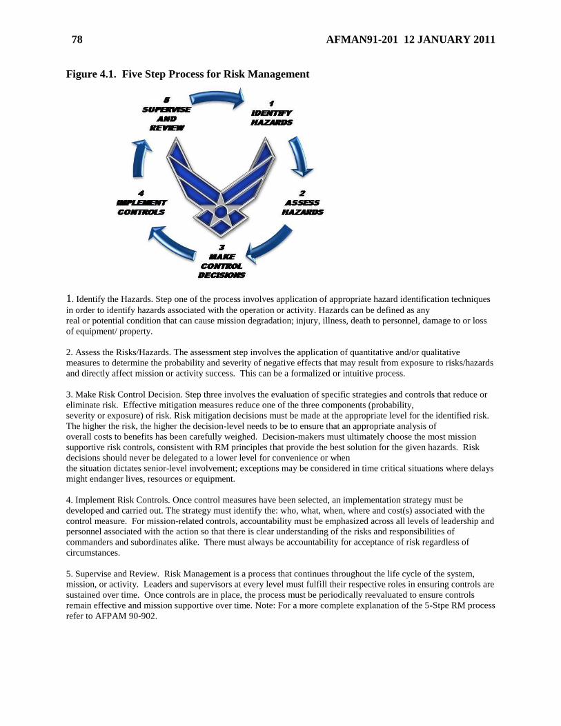
78 AFMAN91-201 12 JANUARY 2011
Figure 4.1. Five Step Process for Risk Management
1. Identify the Hazards. Step one of the process involves application of appropriate hazard identification techniques
in order to identify hazards associated with the operation or activity. Hazards can be defined as any
real or potential condition that can cause mission degradation; injury, illness, death to personnel, damage to or loss
of equipment/ property.
2. Assess the Risks/Hazards. The assessment step involves the application of quantitative and/or qualitative
measures to determine the probability and severity of negative effects that may result from exposure to risks/hazards
and directly affect mission or activity success. This can be a formalized or intuitive process.
3. Make Risk Control Decision. Step three involves the evaluation of specific strategies and controls that reduce or
eliminate risk. Effective mitigation measures reduce one of the three components (probability,
severity or exposure) of risk. Risk mitigation decisions must be made at the appropriate level for the identified risk.
The higher the risk, the higher the decision-level needs to be to ensure that an appropriate analysis of
overall costs to benefits has been carefully weighed. Decision-makers must ultimately choose the most mission
supportive risk controls, consistent with RM principles that provide the best solution for the given hazards. Risk
decisions should never be delegated to a lower level for convenience or when
the situation dictates senior-level involvement; exceptions may be considered in time critical situations where delays
might endanger lives, resources or equipment.
4. Implement Risk Controls. Once control measures have been selected, an implementation strategy must be
developed and carried out. The strategy must identify the: who, what, when, where and cost(s) associated with the
control measure. For mission-related controls, accountability must be emphasized across all levels of leadership and
personnel associated with the action so that there is clear understanding of the risks and responsibilities of
commanders and subordinates alike. There must always be accountability for acceptance of risk regardless of
circumstances.
5. Supervise and Review. Risk Management is a process that continues throughout the life cycle of the system,
mission, or activity. Leaders and supervisors at every level must fulfill their respective roles in ensuring controls are
sustained over time. Once controls are in place, the process must be periodically reevaluated to ensure controls
remain effective and mission supportive over time. Note: For a more complete explanation of the 5-Stpe RM process
refer to AFPAM 90-902.
AFMAN91-201 12 JANUARY 2011 79
Chapter 5
GENERAL EXPLOSIVES FACILITY DESIGN, CONSTRUCTION AND
MAINTENANCE, AND EQUIPMENT DESIGN, MAINTENANCE AND INSPECTION
Section 5A—Introduction
5.1. Applicability.
5.1.1. Unless otherwise specified, the design requirements in this chapter apply to all
existing and new construction of explosives facilities, to include specific explosives facility
designs covered in Chapter 6. Unless specifically excluded, the requirements in this chapter
apply to licensed explosives storage locations and to locations involving explosives
operations which do not require explosives siting. This chapter also provides requirements
for the construction, maintenance, and repair of explosives facilities as well as equipment in
these facilities.
5.1.2. This chapter does not address extraordinarily hazardous situations (e.g., nitroglycerin
manufacturing) that will require special consideration and design features. In these
situations, the MAJCOM will develop specific design criteria.
5.1.3. Additional criteria specific to nuclear weapons storage, handling, and maintenance
facilities apply as provided in AFMAN 91-118, Safety Design and Evaluation Criteria for
Nuclear Weapon Systems.
Section 5B—Glass Panels
5.2. Glass Panels in Facilities Exposed to Explosives Hazards.
5.2.1. For construction of a new occupied facility within an IBD arc, do not use glass panels
unless deemed operationally necessary. If the use of glass panels is deemed operationally
necessary, comply with the following requirements, or process a deviation in accordance
with paragraph 1.4:
5.2.1.1. Design the panels so that they will not break under the expected blast loading;
the framing and sash of such panels must be of sufficient strength to retain the panel in
the structure under the expected blast loading. Or, design the panels so that they will
withstand the same blast loading as the structure; the framing and sash of such panels
must be of sufficient strength to retain the panel until the point of structural failure.
5.2.1.2. Provide engineering analyses and design details, as part of the explosives site
plan package, to demonstrate compliance with paragraph 5.2.1.1. The analyses must
include the information addressed in paragraphs 4.13.2. and 4.13.3.
5.2.2. For modification of an existing occupied facility within an IBD arc, remove existing
glass panels, if practical, as part of the scope of modification. Do not add glass panels unless
deemed operationally necessary. If existing glass panels are not removed, perform a glass
breakage risk assessment (see paragraph 4.13); if the risk assessment shows there will be a
hazard to personnel, use engineering mitigation actions (see paragraph 4.14) to eliminate the
hazard or process a deviation in accordance with paragraph 1.4. If the addition of glass
80 AFMAN91-201 12 JANUARY 2011
panels is deemed operationally necessary, comply with paragraphs 5.2.1.1 and 5.2.1.2 or
process a deviation in accordance with paragraph 1.4.
5.2.3. Existing glass panels that are replaced due to damage (i.e., cracked or broken) must be
replaced with equivalent strength or stronger glass panels.
5.2.4. Glass skylights will not be used in any facility within an IBD arc.
Section 5C—Hazardous Locations
5.3. Hazardous Locations. Comply with NFPA 70, National Electrical Code (NEC), Article
500, Hazardous (Classified) Locations, requirements for the design and installation of electrical
equipment and wiring for hazardous locations. Hazardous locations are those in which
combustible dusts, or flammable vapors or gases are or may be present in the air in quantities
sufficient to produce explosive or ignitable mixtures.
5.3.1. The presence of explosives does not necessarily make an area a hazardous location.
To ensure proper identification of a hazardous location, it is necessary to have knowledge of
the properties of the explosives involved, especially thermal stability and sensitivity to heat
and spark. Use NEC definitions, as modified below, to identify and classify hazardous
locations involving explosives.
5.3.1.1. Areas that contain vapors from explosives will be considered Class I hazardous
locations.
5.3.1.2. Areas in which explosive sublimation or condensation occur or may occur will
be regarded as both Class I, Division 1 and Class II, Division 1.
5.3.1.3. Areas containing explosives dusts or explosives that may, through handling,
produce dust capable of being dispersed in the atmosphere will be regarded as Class II,
Division 1.
5.3.2. Some definitive drawings for explosives facilities may identify the presence of a
hazardous location or require the installation of certain basic electrical equipment to meet
NEC requirements.
5.4. Electrical Equipment in Hazardous Locations.
5.4.1. Installation of electrical equipment in hazardous locations involving explosives will
comply with NEC requirements for the appropriate hazardous location class, group and
division.
5.4.2. Equipment must be approved not only for the class of location, but also for the
explosion properties of the specific gas, vapor, or dust that will be present.
5.4.3. Intrinsically safe equipment must be certified by a reputable testing organization such
as Underwriters’ Laboratories (UL). Such equipment must be used in accordance with the
recommended environmental and operational conditions specified in the certification.
5.4.4. If the properties of an explosive are such that the NEC requirements for electrical
equipment provide inadequate protection under prevailing conditions, use of any of the
following approaches is acceptable:
5.4.4.1. Intrinsically safe equipment.
AFMAN91-201 12 JANUARY 2011 81
5.4.4.2. Purged or pressurized and suitably temperature-limited equipment.
5.4.4.3. Exclusion of electrical equipment from the hazardous atmosphere.
5.4.4.4. Isolation of equipment from the hazardous atmosphere by means of dust, vapor,
or gas-free enclosures with surface temperatures positively maintained at safe levels.
5.4.5. Devices which provide ―cold light‖ through chemical action are acceptable for use in
any hazardous location.
5.5. Interior Surfaces in Class II Hazardous Locations.
5.5.1. Interior surfaces should be smooth, free from cracks and crevices, and have joints
taped or sealed.
5.5.2. If painted, interior surfaces should be covered with a hard gloss paint that is easily
cleaned.
5.5.3. Horizontal ledges which might hold dust will be avoided or beveled to prevent dust
collection.
5.5.4. Cove bases at the junction of the walls and floor are recommended.
5.6. Hardware in Hazardous Locations. To reduce the risk of accidental ignition by spark,
consider the operational conditions in any hazardous location before choosing and installing
hardware. Certain hazards may be sufficient to warrant the use of materials that will reduce the
possibility of sparking.
5.7. Static Electricity in Hazardous Locations. To minimize the risk of ignition of a
flammable or combustible atmosphere in a hazardous location due to static electricity, the
requirements of Section 5E will be met for all hazardous locations.
5.8. Ventilation in Hazardous Locations. Buildings with hazardous locations must comply
with the following ventilation requirements:
5.8.1. Buildings where dust, fumes, or vapors (having explosive potential) are formed will
be passively ventilated, usually at the source of the hazard.
5.8.2. Design ventilation systems so that they have adequate measures for minimizing
(eliminating) static discharge, including measures applied during the activation of manual or
automated ventilation systems.
5.8.3. Equip exhaust fans through which combustible dust or flammable vapor pass with
nonferrous blades (or casting lined with nonferrous material) and approved motors.
5.8.4. Electrically bond and properly ground the entire ventilation system.
5.8.5. NFPA 91, Standard for Exhaust Systems for Air Conveying of Vapors, Gases, Mists,
and Noncombustible Particulate Solids, may be used in the installation of such systems.
5.8.6. For buildings in which there is explosive dust, an air balance that gives a slight
negative pressure within the building is required.
5.8.7. If air conditioning equipment is installed, it should be done as directed in the NFPA
90A, Standard for Installation of Air-Conditioning and Ventilating Systems, and NFPA 90B,
Standard for Installation of Warm Air Heating and Air-Conditioning Systems. Exhaust
systems will be cleaned thoroughly and serviced on a regular schedule. A log will be kept.
82 AFMAN91-201 12 JANUARY 2011
Section 5D—Electric Supply Systems
5.9. Electric Supply Systems. This paragraph does not apply to licensed explosives storage
locations, and locations involving explosives operations which do not require explosives siting.
For QD and fire protection separation requirements between explosives facilities and electric
supply system components (see paragraph 12.84.). Electric lines serving explosives facilities,
including shielded cabling, power cabling, and communication lines will be installed
underground in metal conduit from a point at least 50 feet away from the facility.
5.9.1. The line side of the main disconnecting switch or circuit breaker must have surge
suppression in accordance with UFC 3-520-01, Interior Electrical Systems, and any
Engineering Technical Letters issued specifically for explosives areas.
5.9.2. Surge protection shall be included for all incoming conductors. The surge protection
must include suppression at the entrance to the facility from each wire to ground. All other
metallic utility lines and pipes must be electrically connected to the structural steel of the
building prior to entering the facility.
5.10. Backup Power. An alternate source of power must be available for explosives operations
where the lack of a continuous power supply may cause a fire or explosion, as determined by risk
assessment (see Chapter 4).
Section 5E—Static Grounding and Bonding
5.11. Areas Requiring Static Grounding and Bonding Systems. See Section 7D for static
grounding and bonding requirements during specific operations. Static grounding and bonding
systems are required for:
5.11.1. Hazardous locations (see Section 5C).
5.11.2. Areas where EEDs are exposed.
5.11.3. Areas where exposed explosives are handled.
5.11.4. Areas where explosive components which incorporate an electrical initiating system
are undergoing maintenance; assembly to, or disassembly from, an all-up-round (AUR)
configuration; or electrical connection or disconnection.
5.11.5. Areas where electrically initiated munitions and explosive devices are undergoing
maintenance and electrical test operations and the responsible engineering function has
determined grounding is necessary. This will usually be documented in the specific item TO
5.11.6. Areas where explosives are loaded or unloaded on aircraft (unless exempted per
paragraph 7.14.1 or 7.14.2).
5.12. Static Grounding and Bonding Requirements.
5.12.1. The method generally used to eliminate or reduce the hazard from static electricity is
to provide an electrically continuous path to ground via ground wire, cable, or strap.
5.12.1.1. These grounds shall be one continuous ground wire, cable or strap. Short
ground wires, cables, or straps should not be connected together to make a longer one.
AFMAN91-201 12 JANUARY 2011 83
5.12.1.2. Each ground wire, cable, strap shall be connected to the item and facility
ground individually. Connecting multiple ground wires, cables, or straps to another
ground wire, cable or strap connecting mechanism (alligator clip, clamp, etc.) should be
avoided.
5.12.2. Static grounding bars or other grounding devices may be appropriate for some
operations (see paragraph 7.13.1). Such grounding bars or devices will be located at the
entrance to or within the area where work will be performed.
5.12.3. Wire used as a permanent static ground conductor should be large enough to
withstand mechanical damage and must not be less than American Wire Gauge (AWG) No. 6
(or No. 8 for existing bonds), or a braided cable of equal resistance. Wires used as static
grounds for portable or movable equipment, or for temporary static bonding cables, will be
large enough to carry the expected current load as specified in the item technical data, but
will not be smaller than AWG No. 12 (3/32-inch cable).
5.12.4. Static grounds will be bonded to the facility's grounding system. Static grounds will
not be made to telephone grounds; electrical conduit systems; gas, steam, hot water, or air
lines; sprinkler systems; or air terminals of lightning protection systems (connection to the
―down wire‖ of the system at ground level is authorized).
5.12.5. When all of the objects are conductive, they can be grounded by electrically
connecting all parts to a common ground conductor.
5.12.6. Partial grounding, or using conductors that are too weak or have too much resistance,
may increase the static hazard by providing opportunities for discharge through an
uncontrolled path to ground.
5.12.7. Electrical continuity may be broken by oil on bearings, paint, or rust at any contact
point. To get a continuous circuit, grounding straps should be used to bridge such locations.
5.12.8. Equipment in contact with conductive floors or tabletops will not be considered
grounded.
5.12.9. For explosive facilities, shielded cabling, power cabling, and communication lines
must run underground in metal conduit for at least 15.24 meters (50 feet) prior to entering the
structure. All other metallic utility lines and pipes, including steam, water, and air
conditioning lines must be bonded to the lightning protection system just before they enter
the building.
5.12.10. Electrically energized objects or tools will not be placed on grounded surfaces
where explosives operations are conducted. If electrically energized objects or tools (heat
sealers, heat guns, etc) are required for the operation, these shall be placed on a non-
conductive surface to prevent continuity between the electrically energized object or tool and
the grounded surface.
5.13. Permanent Static Grounding Systems.
5.13.1. A resistance of 25 Ohms or less is required from item connection to facility ground.
In hazardous locations, resistance to ground of 10,000 Ohms or less for equipment static
bonding straps is adequate to bleed off the static charges; continuity across bonds must be
less than 1 Ohm.

84 AFMAN91-201 12 JANUARY 2011
5.13.2. In accordance with AFI 32-1065, Grounding Systems, all permanent static grounding
systems shall be given a continuity test at the time of initial installation and at any time a lack
of continuity is suspected due to damage or corrosion. A resistance reading of 25 Ohms or
less must be obtained. Documentation of initial and recurring testing is required. Consider
equipment (except a belt-driven machine) as a unit in testing of resistance to ground.
5.13.3. Hazardous locations:
5.13.3.1. Ground all conductive parts of equipment in accordance with the NEC.
5.13.3.2. Where the installation permits viewing, make a visual inspection of all static
bonds and grounds for breaks and corroded connections before starting operations on
each day the equipment is to be used. Test any suspected connections and bring them up
to required standards before starting operations.
5.13.4. In non-hazardous locations, static bonding and grounding straps must be inspected
visually for breaks and corroded connections quarterly in accordance with AFI 32-1065.
Suspect connections will be tested for continuity, brought up to required standards, and re-
tested before starting operations.
5.14. Temporary Static Grounding or Bonding Cables.
5.14.1. Temporary static grounding or bonding cables shall be given a continuity test at the
time of their initial placement into service.
5.14.2. Prior to each subsequent use, the cable will be inspected for any evidence of
corrosion or damage.
5.14.2.1. Replace the clamp if jaws are deformed, spring is weak, or other defect is noted
that would prevent a good connection.
5.14.2.2. Replace the cable if more than one third of the cable strands are broken.
Deteriorated or damaged plastic coating does not affect electrical capability of cables.
5.14.2.3. Perform a continuity test if a lack of continuity is suspected due to damage or
corrosion or after any components have been replaced.
5.14.3. A resistance of 10 Ohms or less is required from inside one of the clamp jaws to
inside the other clamp jaw.
5.14.4. Documentation of continuity testing on temporary static grounding or bonding cables
is not required.
5.15. Static Grounding or Bonding Reels.
5.15.1. All installed static discharge reels shall be given a continuity test at the time of their
initial installation.
5.15.2. Prior to each subsequent use, the static discharge reel will be visually inspected for
security of mounting and evidence of any corrosion or damage. Perform a continuity test if a
lack of continuity is suspected due to damage or corrosion or after any components have
been replaced or repaired.
5.15.3. A resistance reading of 10 Ohms or less is required from inside the clamp jaw to the
frame on which the reel is mounted.
AFMAN91-201 12 JANUARY 2011 85
5.15.4. The test will be accomplished by extending the entire length of the cable.
5.15.5. Documentation of continuity testing on temporary static grounding or bonding cables
is not required.
5.16. Belting. If static electricity is a hazard, use non-static-producing belting which has a
resistance to ground not exceeding 600,000 Ohms. This will include belt-driven compressors,
conveyor belts, and so forth. In measuring the total resistance to ground for belt-driven
machinery, do not count the resistance of the belting.
Section 5F—Conductive Floors
5.17. Areas Requiring Conductive Floors. Conductive floors may be required in hazardous
locations and where certain exposed explosives and materials are sensitive (easily detonated or
ignited) to the uncontrolled discharge of static electricity, and the requirements of Section 5E are
deemed inadequate to protect from the hazards of static electricity. Dust-air mixtures of
ammonium perchlorate, tetrytol, and dust of solid propellants are subject to static discharge and
conductive flooring should be considered where they are present.
5.18. Requirements for Conductive Floors.
5.18.1. Conductive floors will be non-sparking.
5.18.2. Conductive floors will be smooth, free from cracks, and of a type that will not
develop surface separations, wrinkle, or buckle under operational loads.
5.18.3. Where washing is required, conductive floors will be able to withstand repeated
applications of hot water and cleaners.
5.18.4. Where conductive floors are required, table tops on which exposed explosives or
dusts are encountered shall be conductive, or covered with a conductive material, meeting the
same requirements as the conductive floor.
5.18.5. In small areas, conductive mats or runners can be suitable in lieu of conductive
floors. Personnel (except electricians performing system checks), in places where conductive
floors or coverings are required and installed, will wear conductive footwear (shoes or
grounding straps).
5.18.6. Where conductive floors are required, the resistance between the ground and the
wearer will not exceed 1,000,000 Ohms; that is, the total resistance of conductive footwear
on a person, plus the resistance of floor to ground.
5.19. Testing and Maintenance of Conductive Floors.
5.19.1. Conductive floors will be tested when installed to ensure that design specifications
are met, and at intervals thereafter as prescribed in AFI 32-1065. Test instruments will not
be used until all exposed explosives and explosives dusts, gases and vapors that are subject to
possible ignition or initiation have been removed from the area.
5.19.2. Do not paint over conductive floors.
5.20. Testing and Maintenance of Conductive Footwear.
5.20.1. Test conductive footwear before each shift.
86 AFMAN91-201 12 JANUARY 2011
5.20.2. Conductive footwear requires care to ensure retention of its conductive properties.
5.20.2.1. When conductive footwear is not in use, it shall be stored in lockers close to the
room where it will be worn; conductive footwear shall be donned at this same location.
5.20.2.2. Take precautions to prevent the accumulation of even a thin layer of dust or
wax which can insulate conductive footwear from the floor.
5.20.2.3. Supervisors will ensure that conductive footwear are not altered so as to negate
their safety features.
5.20.2.4. Only conductive materials will be used in their repair of conductive footwear.
Conductive footwear will be cleaned thoroughly before being repaired.
Section 5G—Installed Systems and Equipment Grounds
5.21. Installed Systems and Equipment Grounds. Attention must be given to the installation
and maintenance of electrical grounding where explosives are involved.
5.21.1. All grounding mediums must be bonded together.
5.21.2. If the structure is equipped with a lightning protection system, all grounds, including
static grounds, must be interconnected as outlined in AFI 32-1065.
5.21.3. Grounding will be tested when installed to ensure that design specifications are met
and at intervals thereafter as prescribed in AFI 32-1065. Document all tests and inspections
on appropriate forms or automated products.
5.21.3.1. Before making any electrical continuity and resistance tests or electrical
repairs, remove all exposed explosives, EEDs, and explosives dust, gases and vapors that
are subject to initiation under the specific circumstances.
5.21.3.2. If there is an operating generator or energized transformer at the location,
connect a shunt grounding strap before opening an installed grounding connection for
repair or replacement.
Section 5H—Lightning Protection Systems
5.22. Facilities Requiring Lightning Protection Systems. Properly maintained lightning
protection systems (LPS) are required for all explosives facilities (to include open locations),
except as noted in paragraph 5.25. The DoD has selected the LPS criteria of NFPA 780,
Standard for the Installation of Lightning Protection Systems, for AE facilities. If LPS test
methods or designs other than prescribed in this section are used, they shall offer equivalent
protection to those prescribed in this section and be approved via the explosives site plan.
5.23. Lightning Protection System Design. Design and installation of a LPS must meet, at a
minimum, the requirements of AFI 32-1065, Grounding Systems and NFPA 780. The LPS must
feature air terminals, down conductors, sideflash protection, surge suppression of data lines and
bonding of all other conductive penetrations into the protected area, and earth electrode systems.
Structural elements of the building may serve as air terminals, down conductors, or the earth
electrode. The LPS must be designed to intercept lightning at a 100 ft or less striking distance
arc in accordance with NFPA 780 (Note: The pitched roof requirements of NFPA 780 may not
be used in lieu of this requirement).
AFMAN91-201 12 JANUARY 2011 87
5.23.1. Air Terminals. An air terminal is a component of an LPS that is able to safely
intercept lightning strikes. Air terminals may include overhead wires or grids, vertical
spikes, or a building’s grounded structural elements. Air terminals must be capable of safely
conducting the current from a lighting strike.
5.23.2. Down Conductors. Down conductors (flat or round) provide low impedance paths
from the air terminals described above to the earth electrode (ground) system. Structural
elements having a high current capacity and a low impedance to ground need not be
augmented with wires. Where wires are used as down conductors, these shall meet the
requirements of NFPA 780.
5.23.3. General Sideflash Protection. Protection from side flash is obtained either by
bonding metallic objects to the down conductors or the earth electrode system, in accordance
with NFPA 780, except as modified herein, or it is obtained by maintaining a separation
distance between metallic objects and these LPS components.
5.23.3.1. Fences and railroad tracks located within six feet of a structure’s LPS shall be
bonded to the structure’s LPS.
5.23.3.2. The reinforcing bars in adjacent structural elements must be joined in a manner
to provide electrical bonding between the elements. This is an absolute requirement for
facilities that are used to store AE. Techniques commonly used and approved in the
construction industry to join reinforcing steel are acceptable for this purpose. The steel
arch of an ECM must be similarly joined to the rebar in the floor.
5.23.4. Sideflash Protection for Nuclear Weapons. The Nuclear Weapon System Safety
Group (NWSSG) adopted a standard sideflash separation distance value of 7-feet as a
conservative baseline for nuclear safety critical operations. In the absence of any specific
additional guidance due to location (see paragraph 5.23.4.2) or weapon configuration (see
Table 5.1), the 7-foot value shall be the sideflash separation distance required. When
weapons are in an operational configuration where no lightning sideflash separation distance
is required, all other separation distance requirements not specifically related to lightning (i.e.
for access, ventilation, inventory, etc.) are still applicable.
5.23.4.1. The sideflash protection requirements for all nuclear weapons, depending on
their operational configuration, are listed in Table 5.1. The term ―major maintenance‖
refers to the weapon configuration resulting from the disassembly or the performance of
any maintenance operations, as currently approved, which could result in exposure of the
weapon’s internal components to electrical energy. Major maintenance does not include
Permissive Action Link (PAL) procedures.
5.23.4.2. Location Considerations for Sideflash Separation Distance.
5.23.4.2.1. If operations are being performed inside a HAS or a PAS and these
operations include weapon configurations that require a separation distance (see
Table 5.1), then:
5.23.4.2.1.1. When using an LPS modified Weapons Maintenance Truck (WMT),
no minimum sideflash separation distance is required between the WMT and the
HAS/PAS provided all additional safety requirements are adhered to in
accordance with TO 11N-50-1007, Transportation Maintenance System
88 AFMAN91-201 12 JANUARY 2011
Operator/User Manual A/S32U-42 and A/S32U-43, including any separation
distance requirements between the weapon and the inside walls of the WMT.
(See paragraph 5.23.4.3 for proper application of separation distance).
5.23.4.2.1.2. When no WMT is being used, a minimum sideflash separation
distance of 7-feet is required between the weapon and the HAS/PAS. (See
paragraph 5.23.4.3 for proper application of separation distance).
5.23.4.2.2. If operations are being performed at any location other than in a HAS or a
PAS and these operations include weapon configurations that require a separation
distance (see Table 5.1), then a minimum sideflash separation distance of 7-feet is
required between the weapon and facility. (See paragraph 5.23.4.3 for proper
application of separation distance).
5.23.4.2.3. The standard separation distance of 7-feet may be reduced by determining
the specific sideflash separation value for a particular facility.
5.23.4.2.3.1. Sideflash separation distance reduction shall be based on Faraday
shield impedance characterization testing and the adequate bonding and
appropriate installation of surge suppression using a methodology approved by
AFSC/SEW prior to implementation.
5.23.4.2.3.2. Documentation of the bonding and surge suppression configuration,
including the associated separation distance calculations, in an attachment to the
explosives site plan, must accompany the characterization test results for formal
review and approval by AFSC/SEW before an exception to the 7-foot standard
separation distance is granted. Changes to the bonding and surge suppression
configuration must be submitted to AFSC/SEW for approval prior to
implementation.
5.23.4.2.3.3. Faraday shield characterization and implementation methodologies
must include specific maintenance and inspection procedures. Until AFI 32-1065
is updated to specifically address Faraday shield sideflash protection devices,
maintenance and inspection of approved systems will comply with the following
requirements.
5.23.4.2.3.3.1. Bonds and surge suppressors shall be visually inspected as a
minimum every six months to validate the installation and serviceability.
Additionally, a visual inspection shall be performed of all surge suppression
devices when a lightning strike occurs to the facility.
5.23.4.2.3.3.2. Electrical resistance measurements of bonds shall be taken, as
a minimum, once every two years. Such measurements are also required
when the facility is subjected to an earthquake, tornado, flood, or other such
acts of nature that could have affected the integrity of the bonds; and any time
modification, maintenance or repair to the structure, penetration or any LPS
component requires the bond or connection to be broken. The bond resistance
should be less than 1 Ohm. Larger readings require tightening or reattaching
of the bonds.
5.23.4.2.3.3.3. Transfer impedance measurements, as determined by Faraday
AFMAN91-201 12 JANUARY 2011 89
shielding characterization testing, shall be taken, as a minimum, once every
ten years.
5.23.4.2.3.3.4. A record of all resistance or transfer impedance measurements
at all required points and of visual inspections shall be maintained for at least
six inspection and testing cycles.
5.23.4.2.3.4. The measures taken to implement a Faraday shield approach for
reducing the required lightning sideflash separation distance in a particular facility
do not impact, adversely effect or relieve the requirements to maintain a
conventional LPS as described in Section 5H and the current version of AFI 32-
1065 (1 Oct 98).
5.23.4.3. The required safe separation distance is properly applied to an item (weapon,
WMT, etc.) to be protected from lightning sideflash by maintaining a minimum free
space separation of the specified distance between the item and the facility’s walls,
ceiling, or any other structural member capable of conducting electrical energy (e.g. steel
columns, rebar-reinforced interior walls, columns or beams).
5.23.4.3.1. Objects in the floor such as concrete rebar, floor grounds, and structural
members of the Weapons Storage Vault (WSV) (when the vault is in a full down
position) do not require the application of the sideflash separation distance.
5.23.4.3.2. If an ungrounded metallic conductor is located within the safe separation
distance of the item being protected, then the shortest free space distance measured
between the metallic conductor and any structural member capable of conducting
electrical energy shall be at least equal to the full separation distance (7’ default)
minus the shortest free space distance measured between the metallic conductor and
the item being protected.
5.23.4.3.3. Transient or temporary infringement of the sideflash separation distance
requirement (e.g. the movement of personnel through the facility or the requirement
to use an overhead crane in the course of approved maintenance procedures) can be
permitted. These actions shall be avoided whenever possible or their duration shall
be minimized while still allowing required maintenance operations to be safely
completed. These violations are not justified by issues of convenience or for the sole
purpose of ease of operations.
5.23.4.4. Deviations from paragraph 5.23.4 must be approved by AFSC/SEW (see
paragraph 1.4.1)
5.23.5. Surge Protection for Incoming Conductors. A LPS shall include surge protection
for all incoming conductors. The surge protection must include suppression at the entrance
to the building from each wire to ground. Shielded cabling, power cabling, and
communication lines shall be buried underground in metal conduit for a minimum of 50 feet
before entering the structure. All other metallic utility lines and pipes must be electrically
connected to the LPS or the structural steel of the building just before they enter the building.
5.23.6. Earth Electrode System. Earth electrode systems dissipate the current from a
lightning strike to ground. Earth electrode systems may be concrete encased electrodes,
ground loop conductors, radials, grounding rods, ground plates, a conductor immersed in
90 AFMAN91-201 12 JANUARY 2011
nearby salt water, chemical grounds that are installed for the purpose of providing electrical
contact with the earth, or combinations of these.
5.23.7. Underground Storage Facility. An underground storage site requires protection
against lightning only for exposed or partially exposed parts. Lightning protection
requirements will be considered on a site specific basis.
5.24. Lightning Protection System Inspection, Maintenance, Testing, and Training. LPS
must meet, at a minimum, the requirements of AFI 32-1065 and NFPA 780. Maintenance shall
be performed to ensure that the integrity of the LPS conforms with the criteria of NFPA 780 and
AFI 32-1065.
5.24.1. Visual inspection. The LPS will be periodically inspected as prescribed in AFI 32-
1065.
5.24.2. Electrical tests. The LPS shall be periodically tested electrically as specified below
and as prescribed in AFI 32-1065.
5.24.2.1. Bonding (resistance) tests shall be conducted periodically (or after facility
modification that may affect bonding). A maximum resistance value of one Ohm is
permitted across all bonds.
5.24.2.2. Resistance to earth tests of LPS will be conducted periodically during the same
season of the year (or after facility modification that may have affected the system). The
maximum resistance to earth shall not exceed 25 ohms.
5.24.3. Records and Data. Records and test measurement data of resistance to earth tests
and bonding tests shall be kept on file for the last six inspection cycles. These records shall
be reviewed for trend analysis as prescribed in AFI 32-1065.116
5.24.4. Training. Personnel responsible for maintenance, inspection and testing must be
familiar with the fundamentals described in NFPA 780 and this section as they relate to
explosives facilities to ensure inspection and test requirements above are met. See AFI 32-
1065 for specific training requirements.
5.25. Lightning Protection System Exceptions. Properly maintained LPS are required for
explosives facilities, with the following exceptions:
5.25.1. Air terminal systems are not required on a HAS, a PAS, a metal aircraft shelter, or an
earth covered magazine, provided:
5.25.1.1. All reinforcing steel in the walls and floors are properly bonded and grounded.
5.25.1.2. Metal ventilators at least 0.188 (3/16) inches thick are grounded.
5.25.1.3. Metal ventilators less than 0.188 (3/16) inches thick are protected by an air
terminal.
5.25.1.4. Down conductor, sideflash protection, surge suppression, and earth electrode
system requirements of paragraph 5.23 are met.
5.25.2. A LPS is not required for licensed explosives storage locations outside the explosives
storage area but situated in buildings primarily used for other purposes and that have
relatively small quantities of explosives. (Note: This exemption is made because of the
explosives; other contents of the building may require a LPS.)
AFMAN91-201 12 JANUARY 2011 91
5.25.3. A LPS is not required for locations involving explosives operations which do not
require explosives siting. (Note: This exemption is made because of the explosives; other
items at this location may require a LPS.)
5.25.4. An ―integral‖ LPS is not required for an all-metal building that has been shown to
meet the additional criteria of a ―metallic cage‖ system, as both are defined in NFPA 780.
This exception must be approved by AFSC/SEW prior to operational use of the building in
this configuration (see paragraph 1.4).
5.25.5. The following locations do not require a LPS provided that the responsible
commander accepts the loss of resources and structure and any potential collateral damage to
other nearby exposures. The commander’s risk acceptance must be documented by letter
(i.e., signed by the commander stating he/she understands and accepts the potential loss of
resources and structures at the location without LPS and any potential collateral damage to
other nearby exposures) and this letter must be submitted with the explosives site plan.
5.25.5.1. Explosives locations served by a local lightning warning system to permit the
controlled termination of operations at the issuance of a Lightning Watch and immediate
personnel protection actions at the issuance of a Lightning Warning as prescribed in
Section 7H.
5.25.5.2. Facilities containing only ammunition or explosives that cannot be initiated by
lightning, as determined by AFSC/SEW and approved by DDESB, and where no fire
hazard exists.
5.25.5.3. Facilities where personnel are not expected to sustain injury and at the same
time, the resulting economic loss of the structure, its contents and/or surrounding
facilities is minimal.
5.25.5.4. Facilities used for temporary (non-recurring) storage of munitions.
5.25.5.5. Structures, facilities, or mobile equipment housing explosives or explosives
operations not regularly situated at a fixed location.
5.25.5.6. Structures and facilities limited to the storage or handling of small arms
ammunition where the value of the ammunition is $10,000 or less.
5.25.5.7. Lightning protection systems may be omitted on EOD intentional detonation
and proficiency training ranges, and holding areas sited within the range boundary. A
commander’s risk acceptance memo is not required. Apply the requirements set forth in
paragraph 5.25.5.1.
5.25.6. Lightning protection systems may be omitted on flightline PESs if the system
interferes with flightline criteria contained in UFC 3-260-01, Airfield and Heliport Planning
and Design. A commander’s risk acceptance is not required. See Section 7H for procedures
in the event of electrical storms.
5.25.7. Large catenary systems that cannot conform to the bonding distances calculated from
the equations provided in AFI 32-1065 shall be considered under the provision in paragraph
5.22. Engineering analyses shall be provided to ensure variances provide equivalent
protection prior to submission to the DDESB for approval.
92 AFMAN91-201 12 JANUARY 2011
5.25.8. ECMs that constitute a metallic cage, as defined in NFPA 780, and that do not
contain any energized or unbounded metallic penetrations, do not require earth resistance
testing.
Section 5I—General Design Considerations for Explosives Facilities
5.26. Blowout-type Construction. Roofs and walls of explosives facilities should be as light in
weight (weak) as practicable. Design facility features (e.g. roofs, walls, blow-out panels) to
allow venting of an internal explosion with the minimum number of large fragments. Avoid
installing hardware (including pipes and ducts) on light blowout-type walls, roofs or panels; if
unavoidable, select materials or items that will not yield heavy fragments in an explosion. The
use of frangible panels should be considered in the design of HD 1.3 facilities where high
overpressures from a detonation or a confined deflagration are expected (see HNDED-CS-93-7,
Hazard Division 1.3 Passive Structural Systems Design Guide). Exceptions to this paragraph are
made where design requirements such as the following must be met: fire walls, substantial
dividing walls, special roof loading, external overpressure protection, and specialized
manufacturing facilities. This paragraph does not apply to licensed explosives storage locations,
and locations involving explosives operations which do not require explosives siting.
5.27. Non-combustible Construction. Construct exterior walls and roof coverings of
explosives building out of non-combustible materials. Non-combustible material will be used
for interior surfaces of explosives buildings (see UFC 3-600-01, Fire Protection Engineering for
Facilities. If it is necessary to use combustion-supporting materials in the interior of an
explosives building, treat or cover all exposed surfaces with fire-retardant material. This
paragraph does not apply to licensed explosives storage locations, and locations involving
explosives operations which do not require explosives siting.
5.28. Underground Explosives Storage Facilities. All wiring and electrical equipment in
underground storage facilities will, in addition to any other requirements of this chapter, be of
moisture and corrosion resistant materials and construction unless a site specific analysis
indicates that such construction is not necessary. Underground facilities must have emergency
lighting systems to provide minimum illumination in the event of a power failure.
5.29. Outdoor Explosives Storage Sites. This paragraph does not apply to licensed explosives
storage locations, and locations involving explosives operations which do not require explosives
siting.
5.29.1. Outdoor explosives storage sites will have a minimal slope, be well drained, and free
from unnecessary combustible materials.
5.29.2. Adequate dunnage is needed, especially between the stack and an unimproved
surface to ensure stack stability. The dunnage, supporting timbers, or platform on which
explosives are stored will be built and placed to prevent falling, sagging, or shifting of the
explosives. See specific item TOs.
5.29.3. Nonflammable or fire-resistant, waterproofed, overhead covers will be provided for
packaged explosive items unless the item is contained in packing designed and approved for
unprotected outside storage. There must be at least 18 inches between the top of the stack
and the cover. If airspace is kept between the cover and the stacks, the sides of covered
stacks may be protected by nonflammable or fire-resistant, waterproof covers.
AFMAN91-201 12 JANUARY 2011 93
5.30. Stairways. Stairways will conform with Air Force Occupational Safety and Health
(AFOSH) standards and NFPA 101, Life Safety Code requirements. Open-sided stairways in an
explosives building (or in one where a dangerous fire hazard exists) must have handrails at least
42 inches high. They must have mid-railings to preclude falls when vision might be impaired by
smoke, injury or when panic might result. Open risers should be avoided.
5.31. Fixed Ladders. Fixed ladders should conform to the American National Standards
Institute (ANSI) Safety Code A14.3, Ladders – Fixed – Safety Requirements, and AFOSH
standards.
5.32. Platforms, Runways, and Railings. Platforms, runways, and railings should conform
with AFOSH requirements.
5.32.1. Platforms and runways less than 30 feet long require one stairway or fixed ladder.
Those over 30 feet long or more than 250 square feet in area require two stairways or ladders.
5.32.2. Platforms, floor openings, runways, tanks, or open vats comply with AFOSH 91-501,
Air Force Consolidated Occupational Safety Standard.
5.32.3. Permanent railings should be of metal except in those process buildings where metal
railings would increase the hazard.
5.33. Passageways. If weather-protected passageways (ramps) are needed between buildings or
magazines, they should have suitable fire stops between the buildings.
5.34. Walkways. Walkways at the entrances to or between adjacent operating buildings
containing explosives will be hard surfaced or boardwalks. These walkways should be kept free
from foreign material. Foot brushes, door mats, or scrapers should be provided at the entrance of
each building, except magazines. Special attention will be given to passageways, walkways, and
stairs which have been subjected to the effects of inclement weather.
5.35. Roads. This paragraph does not apply to licensed explosives storage locations, and
locations involving explosives operations which do not require explosives siting, unless they are
located within an explosives storage area.
5.35.1. Good all-weather roads should be provided to, and within, the explosives area.
5.35.2. Road systems serving groups of magazines or explosives buildings will be arranged
without dead ends so that motor vehicles carrying explosives cannot be isolated. To prevent
dead ending, interconnecting roads for magazine service roads need only be passable trails
adequate to accommodate the typical vehicles used at the installation.
5.35.3. Roads serving a single magazine or explosives processing building (including its
service facilities) may dead end at the magazine or building. The road system should be
designed to eliminate the need for passing through an intermediate explosives area when
traveling between one operating area and another, within the same explosives storage area.
5.36. Gates. There is no mandatory safety requirement for more than one personnel gate in the
fence around an explosives area. Weapons Safety, Security and Civil Engineering usually
determine how many gates are needed after considering all elements of the situation.
Consideration should be given to providing alternate personnel gates for a single event
emergency. This paragraph does not apply to licensed explosives storage locations, and
94 AFMAN91-201 12 JANUARY 2011
locations involving explosives operations which do not require explosives siting. Consider
alternate ways of evacuating an explosives area based on where explosives events may occur.
5.37. Drainage. Provide adequate drainage for access and internal roads and all explosives
locations. Provide magazines with condensation drainage from the storage facility interiors. This
paragraph does not apply to licensed explosives storage locations, and locations involving
explosives operations which do not require explosives siting.
5.38. Drains and Sumps. The following requirements apply to facilities which handle liquid
explosives or liquids containing explosive waste:
5.38.1. When lines are required for draining liquid explosives or liquids containing explosive
waste, they will be free of pockets and low spots. The drain line will be sloped at least one
quarter inch per foot so that explosives will not settle in the drain line. The drain system will
include a sump or basin so explosives can be removed.
5.38.2. Bolted sump tanks or other types of construction that allow the explosives to settle in
obscure or hidden spaces are prohibited. Avoid any deposition of explosives from sump
effluent due to drying, temperature changes, or interaction with other industrial
contamination. Use sweeping and other dry-collecting measures to keep explosives which
are appreciably soluble in water out of the drainage system.
5.38.3. Sumps will be designed so that suspended and solid explosive material that may
settle cannot be carried in the wash waters beyond the sumps. They will be constructed so
that the overflow will not disturb any floating solids. The design will allow enough settling
time, based on the settling rate of the material and the usual rate of flow. It will allow the
collected explosives to be removed easily and allow those which float on water to be retained
until they can be skimmed from the water surface.
5.38.4. In all new construction, drains between the source of explosives and the sump will be
troughs with rounded bottoms. The drains will have removable, non-sparking, ventilated
covers for ease of inspection for accumulated explosives. Waste liquids will not be run into
closed drains and sewers.
5.38.5. Drains will be inspected periodically and steps taken to prevent the buildup of
explosive deposits. Drains and sewers containing explosive waste will not be connected to
the normal sewage systems. All residue from hazardous material clean-up operations is
considered hazardous waste and shall be disposed in accordance with AFI 32-7045,
Environmental Compliance Assessment And Management Program (ECAMP) and AFPD 32-
30, Explosive Ordnance Disposal.
5.39. Tunnels. Tunnels must be drained, ventilated, well lighted, and have at least two exits.
Water and steam service lines in tunnels will be lagged with suitable insulation. Tunnels
between buildings that contain explosives will be built to resist the shock wave and blast of an
explosion (see DoD 6055.09-M, DoD Ammunition and Explosives Safety Standards, for design
guidance). Only authorized personnel will enter the tunnels.
5.40. Laundries. Laundries for washing uniforms and rags that are contaminated with
explosives must comply with the following requirements:
5.40.1. The laundry will include a safe place to store uniforms and rags that are
contaminated with explosives before washing. Sumps will also be provided to remove
AFMAN91-201 12 JANUARY 2011 95
explosives from waste water. There should be facilities available to test whether the
contaminant (particularly any insoluble toxic substance) has been removed. Contact
Environmental Management for assistance.
5.40.2. Commercial businesses laundering such articles will be informed of the nature of the
explosives contamination and possible dangerous chemical reactions.
5.41. Steam for Explosives Processing or Facility Heating. This paragraph does not apply to
licensed explosives storage locations, and locations involving explosives operations which do not
require explosives siting.
5.41.1. Steam used to heat buildings that contain explosives must not exceed 228 oF. Process steam may exceed this if necessary but will not exceed 250
oF (121 C). (Process
steam is steam that is in direct contact with explosives or which, in case of equipment failure,
would exhaust directly into contact with explosives or explosive fumes.) However, for TNT
specifically, the maximum temperature allowed for processing is 240 oF.
5.41.2. Steam or hot water pipe surfaces in contact with wood, paper, or other combustible
materials must never be hotter than 160 oF. If the hot water pipes and the steam lines are
hotter than this, they must be covered and painted with an impervious material or otherwise
protected against direct or prolonged contact with these items.
5.41.3. Where a reducing valve is used, a relief valve should be installed on the low pressure
piping. The production of superheated steam caused by the throttling action of reducing
valves will be prevented by positive means, preferably by using a ―water leg‖ or water
column to control steam pressure of 5 psi or less.
5.41.4. Where close control of steam temperature is needed, indicating and recording
pressure or temperature gauges should be installed. Such devices should be periodically
tested and the test results recorded.
5.41.5. Where circulating hot water is used for heating, the installation and operating
conditions will conform to AFI 32-1068, Heating Systems And Unfired Pressure Vessels.
5.41.6. In explosives handling or storage locations where resistance to ground is high, steam
or hot water lines should be grounded where they enter buildings.
5.41.7. A hot work permit is required to use any equipment exceeding 228o F in a building
containing explosives.
5.42. Magazine Ventilation and Vermin-Resistance.
5.42.1. Provide magazines with appropriate means of air circulation or dehumidification,
when required by civil engineering, logistics, or health directives. (Note: Do not install
ventilators in 3- or 7-bar rated earth-covered magazine designs unless allowed by the
DDESB-approved definitive design drawing to ensure the ECM’s strength rating is not
affected.
5.42.2. Magazine vents (when installed or repaired) must prevent the entry of sparks and
burning embers, or have fusible links to close the vents when an outside fire threatens the
magazine. Where fusible links are installed, leave unpainted, and ensure they are
serviceable, properly installed, and rated for a maximum temperature of 155o F to 165
o F
(68.3o C to 73.8
o C) NSN 4210-00-033-6032 or suitable substitute. Existing magazine vents
96 AFMAN91-201 12 JANUARY 2011
that do not prevent the entry of sparks and burning embers may continue to be used until
repaired or replaced; however, it is strongly recommended that these vents be evaluated by
civil engineering (base fire marshal or designate) for their ability to prevent the entry of
sparks and burning embers.
5.42.3. Provide magazines with vermin resistance, when required by civil engineering,
logistics, or health directives.
Section 5J—Emergency Exits for Explosives Buildings
5.43. General. Use the ANSI Safety Code A156.3, Building Exits, and NFPA 101 as a guide in
constructing emergency exits and fire escapes.
5.43.1. Exterior fire escapes from a building with two or more stories must be of non-
combustible material. They should be separated from the interior of the building by fire-
resistant walls.
5.43.2. Fire escape stairs will be arranged so they are exposed to the smallest number of
window and door openings. All openings will be protected as required by the NFPA 101.
5.43.3. Fire walls are designed to limit the spread of fire to only one zone of a facility. They
are normally extended through the roof of the building to prevent a fire on one side of the fire
wall from immediately spreading to the remainder of the facility. Construct proposed fire
walls as prescribed in UFC 3-600-01, Fire Protection Engineering for Facilities. Protect any
openings through the fire wall as described in the NFPA 80, Standard for Fire Doors and
Other Opening Protectives, and NFPA 221, Standard for Fire Walls and Fire Barrier Walls.
5.44. Building Exits.
5.44.1. One properly located exit is suitable for small operating rooms or cubicles which
have substantial dividing walls on three sides.
5.44.2. In larger buildings or rooms, at least two exits remote from each other (regardless of
dimensions), will be provided for each operating room or building containing explosives.
5.44.3. If more than eight persons are occupying a room containing explosives, it should
have more than one exit or one exit for each multiple of five persons (or fraction thereof).
Coordinate with the installation’s Ground Safety (SEG) and Fire Marshall for the number of
exits required based on occupancy.
5.44.4. Exits shall be at least 32 inches wide by 80 inches high. However, in determining
the total number of exits required, available space (in multiples of 32 inches of width) may
be considered additional exit units. Exits should be spaced equally about the perimeter of the
building. Refer to NFPA 101, Life Safety Code, paragraph 7.2.1.2.3.2, for exceptions to the
32 inch width.
5.44.5. Exits shall be in accordance with NFPA 101. Exits should lead directly outside.
Plan each exit to avoid obstructing the escape of personnel. Do not place explosives,
equipment, and operating materials between personnel and exits.
5.45. Exit Doors.
AFMAN91-201 12 JANUARY 2011 97
5.45.1. ECM doors are not authorized for new construction projects used as operating
locations or for existing ECMs converted to use as operating locations. Existing operating
locations using ECM doors may be grandfathered if the ESP has been formerly approved by
the DDESB or AFSC.
5.45.2. Exit doors in operating buildings will open outward.
5.45.3. During operating hours, exit doors may be fastened with dead-bolt panic hardware
that cannot be operated from the outside.
5.45.4. Exit doors shall never be less than 32 inches (refer to NFPA 101, Life Safety Code,
paragraph 7.2.1.2.4 for exceptions to the 32 inch width) by 80 inches high.
5.45.5. Do not obstruct exit doors or departure routes.
5.45.6. Exit doors should be panel or flush surface type construction except for existing
storage magazines already approved by AFSC or DDESB.
5.45.7. Vision panels in each door are desirable. The using agency may omit them for
security. Vision panels should be in the upper half of the door, not exceed 100 square inches,
and glazed with acrylic plastic or equivalent material. They should be of shatter resistant,
non-combustible material or slow-burning material of a type that is practically smokeless.
The requirements of Section 5B do not apply to vision panels in exit doors.
5.46. Safety Chutes. Safety chutes will be provided as exits from multistory hazardous
locations where rapid egress is vital and cannot be otherwise provided.
5.46.1. Supporting members for safety chutes should be made of non-combustible materials
and anchored to structural members designed to provide resistance to the effects of an
explosion or fire.
5.46.2. These chutes must be provided for work levels above the ground floor. They should
be placed on opposite sides of the operation (so that people will not be trapped by a fire
between them and a single chute).
5.46.3. Exits to safety chutes will open on a platform at least 3 feet square, equipped with
guardrails. The chutes will begin at the outside edge of the platform.
5.46.4. Landings from safety chutes should be located where escape routes will be free from
tripping hazards, low guy lines, drains, ditches, or other obstructions.
5.46.5. A manual or automatic tripping device should be installed at or near the entrance to
chutes to give an alarm in the operating building and nearby structures. This tripping device
may also actuate deluge valves and water curtains in the building or room affected.
5.46.6. Recommended safety chute dimensions and construction are: angle, 40-50 degrees
with the horizontal; depth of chute, 24 inches; radius at bottom of chute, 12 inches. The
lower end of the chute will not be over 24 inches above the ground. It will have enough of a
horizontal run to prevent an injury to the employee because of the rate of fall (induced speed)
during the exit.
5.46.6.1. Chutes 40 feet long require 6 feet of horizontal run.
5.46.6.2. The juncture of sections will be well-rounded and must overlap in the direction
of travel.
98 AFMAN91-201 12 JANUARY 2011
Section 5K—Explosive Dust Collection Systems
5.47. Vacuum Collection. Vacuum (aspirator) systems with a wet-type collector that moistens
explosive dust close to the point of origin and keeps it wet until the dust is removed for disposal
are preferred. However, some dusts, (e.g., Explosive D) should be collected in a dry-type
system.
5.47.1. Vacuum systems must be arranged so each type of explosive is collected separately
or so dissimilar hazards (for example, black powder with lead azide) are not mixed.
5.47.2. Provision should be made for the proper liberation of gases that may be formed in a
vacuum system.
5.47.3. Vacuum systems used to collect more sensitive explosives (such as black powder,
lead azide, mercury fulminate, tracer, igniter, incendiary compositions, and pyrotechnic
materials) should be used only for operations with fuzes, detonators, small arms ammunition,
and black powder igniters. Wet-type collectors are required, with a compatible wetting agent
close to the point of intake.
5.48. Location of Dry-Type Collection Chambers.
5.48.1. Stationary dry-type collection chambers should be located outside of operating
buildings, in the open or in a separate building used exclusively for collection chamber.
5.48.1.1. There must be a protective barrier [e.g. operational shield, barricade, SDW]
between the operating building and the outside location or separate building where the
vacuum collection chamber is placed.
5.48.1.1.1. If the chamber contains 25 pounds of explosives or less, the protective barrier
will be located at least 8 feet from the operating building.
5.48.1.2. If the chamber contains more than 25 pounds of explosives, the protective
barrier will be separated from the operating building by a minimum of intraline distance
based on the quantity of explosives in the chamber.
5.48.1.3. When it is not practicable to locate dry-type vacuum collection chambers
outside the operating building, a separate room within the building may be set aside for
the purpose. This room must not contain other operations and never be used as a
communicating corridor or passageway between other operating locations within the
building when explosives are being collected. If more than one collection chamber is to
be placed in the room, the room will be subdivided into cubicles separated by SDWs.
Not more than one collection chamber will be in a single cubicle.
5.48.2. Portable dry-type vacuum collectors will not be placed in a bay or cubicle where
explosives are present. If they do not contain more than five pounds of explosives, they may
be placed outside the building or in a separate cubicle with SDWs. If they contain more than
five pounds, the requirement for stationary collectors will be met.
5.49. Location of Wet-Type Collection Chambers. If stationary and portable wet-type
collection chambers do not contain more than five pounds of explosives, they may be placed in
operating bays or cubicles. If placed in separate cubicles, the limits for each one may be 15
pounds. If they contain more than 15 pounds, the location requirements for dry-type collectors
will apply.
AFMAN91-201 12 JANUARY 2011 99
5.50. Design and Operation of Collection Systems.
5.50.1. The entire system will be electrically grounded and the grounds tested semiannually.
5.50.2. The system will be designed so that metal parts do not pinch explosives or explosive
dusts.
5.50.3. Pipes or tubes through which the dust travels should have flanged, welded, or rubber
connections. Threaded connections are not allowed.
5.50.4. The system will be designed to reduce accumulation of explosive dust in parts other
than the collection chamber.
5.50.5. Long radius turns (centerline radius at least four times the diameter of the duct) will
be used in the duct work.
5.50.6. The number of points of application of vacuum should be kept to a minimum.
5.50.7. Each room requiring vacuum collection should have a separate exhaust line to the
primary collection chamber. No more than two bays will be serviced by a common leader to
the primary collection chamber.
5.50.8. The vacuum line should be as short as possible from points of application of vacuum
to the wet collectors.
5.50.9. The number of wet primary collectors serviced by a single secondary collector
should be kept at a minimum. Not more than two dry primary collectors should be connected
to a single secondary collector (wet or dry-type).
5.50.10. If an operation does not create an airborne concentration of dust, a manually
operated suction hose to remove explosive dust is preferred.
5.50.11. Manually operated hoses should not be connected to explosive dust-producing
machines. A permanent attachment increases the risk of propagation through the collection
system should a detonation occur at the dust-producing machine.
5.50.12. In dry vacuum collection systems, two collection chambers should be installed in
series, ahead of the pump or exhaust.
5.50.13. Wet collectors must provide for immersion of explosives to break up air bubbles, to
release airborne particles, and to remove airborne moisture before it leaves the collector.
This will keep moistened particles of explosives from entering the small piping between the
collector and the exhaust or pump.
5.50.14. Explosive dust will be removed from the collection chamber at least once each shift
to eliminate unnecessary and hazardous concentrations of explosives. The entire system
should be cleaned weekly, dismantling the parts if necessary.
Section 5L—Water Supply and Fire Suppression Systems for Explosives Facilities
5.51. Water Supply for Explosives Manufacturing Areas and Loading Plants. An outside,
underground, looped system of mains should be installed. The water distribution system will
meet the requirements of UFC 3-600-01 and the NFPA 1142, Standard on Water Supplies for
Suburban and Rural Fire Fighting. Mains will be valved properly and will not extend under
explosives locations.
100 AFMAN91-201 12 JANUARY 2011
5.52. Automatic Sprinkler Systems.
5.52.1. Certain buildings in explosives manufacturing, surveillance, and inspection or
ammunition workshop areas (for example, the receiving building in a load line) may require
automatic sprinkler systems. The proper system must be determined by engineering studies
of the hazards involved. Each system must be equipped with an audible warning device to
alert personnel. Sprinkler systems in each building must be connected into the central alarm
location. Sprinkler systems will be installed as prescribed in UFC 3-600-01.
5.52.2. When explosives facilities are placarded for ―Apply No Water‖, automatic sprinkler
systems will only be disabled after a risk assessment has been accomplished/approved by the
local fire chief. If the risk assessment indicates the continued use of the automatic system is
appropriate (e.g. to keep a potential fire from reaching the explosives items), the presence of
the ―Apply No Water‖ and an operable automatic sprinkler system does not constitute a
violation of this standard. In all cases, the audible warning device must remain operable.
5.53. Deluge Systems. Machinery or operations in which there is a process fire hazard will
have an auto deluge system as required by an engineering study.
5.53.1. Quick-acting sensors such as ultraviolet detectors will be used. In addition, hand-
operated, quick-acting deluge control equipment should be provided.
5.53.2. Control devices used should be actuated by rate of rise, fixed temperature, or their
combination, as appropriate. If the system contains electrical components, the controls will
be placed in enclosures approved by the NEC.
5.53.3. Deluge systems should be charged with steam, water, or chemicals. This depends on
the expected character of the fire to be controlled, as determined by engineering studies of
the hazards and NFPA 13, Standard for the Installation of Sprinkler Systems, and NFPA 16,
Standard for the Installation of Foam-Water Sprinkler and Foam-Water Spray Systems.
5.53.4. If there are two or more deluge systems in the same fire area, supply mains and the
arrangements and size of the system riser will provide each system with the required
quantities of water per head.
5.53.5. A device will be installed on the supply side of the system so that it will actuate an
audible warning device in affected operating areas when the pressure fails.
5.53.6. Operations protected by a deluge system should be stopped immediately if the
system fails and should not be resumed until adequate protection is provided.
Section 5M—Monitoring of Design and Construction of Explosives Facilities
5.54. Monitoring of Design of Explosives Facilities. Weapons Safety and Civil Engineering
shall jointly ensure the design requirements of this chapter, and Chapters 4 and 6, are properly
incorporated into design specifications (to include the statement of work when design and
construction effort is being contracted) and as-built drawings for new explosives facilities.
Additionally, those requirements that apply to nuclear weapon storage, maintenance, and
handling facilities as defined in AFMAN 91-118, Safety Design and Evaluation Criteria for
Nuclear Weapon Systems, must also be addressed in construction planning of new facilities for
these purposes.
AFMAN91-201 12 JANUARY 2011 101
5.55. Monitoring of Construction of Explosives Facilities. In regards to the actual
construction of explosives facilities, Weapons Safety and Civil Engineering shall jointly:
5.55.1. Ensure compliance with the final approved construction drawings with regard to
design requirements driven by explosives safety considerations.
5.55.2. Ensure any changes that affect explosives safety considerations are reflected on the
as-built drawings and the explosives site plan updated if necessary.
5.55.3. Ensure that the actual construction location of sited explosives facilities complies
with the approved explosives site plan.
5.55.4. Ensure temporary construction workers are provided protection from explosives in
nearby facilities as required in paragraph 12.17.11.
5.55.5. Ensure explosives in nearby facilities are protected from temporary construction
operations. Consideration should be given to fire hazards and radio frequency (RF) hazards.
Section 5N—Maintenance and Repair of Explosives Facilities and Equipment
5.56. Removal of Explosives. Supervisory and weapons safety personnel will determine, based
on a risk assessment (see Chapter 4), whether explosives must be removed prior to performing
maintenance and repair of explosives facilities, or maintenance and repair of equipment in
explosives facilities.
5.56.1. Only perform maintenance and repair in the interior of an ECM that contains bulk
explosives if the explosives are physically protected and a risk assessment (see Chapter 4)
shows that hazards to the explosives can be adequately controlled.
5.56.2. Because electricians are not allowed to work on live electrical equipment while
wearing conductive shoes, remove all explosives from areas with conductive floors before
proceeding with the electrical work.
5.57. Requirements for Maintenance and Repair With Explosives Present.
5.57.1. Brief maintenance personnel on the hazards involved and precautions needed to
perform the work safely, and actions to take in the event of an accident. This includes self-
help projects.
5.57.2. If hazards warrant, trained weapons safety personnel must monitor repair activities
for safety. The monitor will halt repair activities when, in his or her opinion, hazards are
being created. The senior supervisor of the facility will resolve the problem before resuming
operations.
5.57.3. Keep the floor clean and free of extraneous materials and equipment in the
immediate work area.
5.57.4. Hot Work.
5.57.4.1. Don't use flame or heat-producing equipment inside the facility unless facility
contents are protected from the flame, sparks and heat by physical separation or
shielding.
102 AFMAN91-201 12 JANUARY 2011
5.57.4.2. Keep flame or heat-producing equipment used outside the facility as far as
practicable from all explosives (to include explosives in nearby facilities). When needed,
use baffles and screens to confine sparks and flames.
5.57.4.3. Meet applicable requirements of AFOSH Standard 91-5, Welding, Cutting, and
Brazing.
5.57.4.4. Notify the fire department before work begins.
5.57.5. Maintenance personnel must wear conductive footwear in areas with conductive
floors.
5.57.6. Ensure RF hazards presented by maintenance and repair operations are evaluated and
controlled in accordance with Chapter 9.
5.58. Maintenance of Explosives Facilities.
5.58.1. Annually check the depth of the earth cover on ECMs to ensure it is at least 2 feet.
MAJCOMs may require more frequent inspections based on environmental conditions.
ECMs with a suitable material finish (e.g., geotextiles, gunite, asphalt) do not require a depth
check as long as there are no signs of the earth cover washing out from underneath the
suitable material. If the earth cover erodes to less than 2 feet, repair as soon as practical (not
to exceed 90 days) or classify as an above-ground magazine (Note: Barricaded above-
ground magazine criteria may be used if the remaining earth cover meets the barricade
criteria of Section 6E).
5.58.2. Periodically check ventilators to ensure they function properly. Ventilators may be
closed where blowing snow or humid air would increase condensation. They may also be
closed to protect supplies from blowing sand. Set up controls to make sure heat does not
build up within the storage space.
5.58.3. Periodically check fusible links to ensure they are unpainted, serviceable, properly
installed, and temperature-rated per paragraph 5.42.2.
5.59. Maintenance and Repair in Hazardous Locations. Before beginning maintenance and
repair in a hazardous location, a weapons safety representative will ensure the area is inspected
for the presence of explosives residue. Maintenance personnel must provide for the removal of
all hazardous materials, to include removal of all explosive residue material from equipment,
crevices beneath floors, within walls and pipes, and under fittings where explosives may have
collected. The area should be washed down thoroughly.
5.60. Maintenance and Repair of Hazardous Location Equipment and Electrical
Installations. Extraordinary care will be taken in the maintenance and repair of equipment and
electrical installations in hazardous locations.
5.60.1. Equipment and electrical installations must be periodically inspected and maintained
by qualified personnel, with a written record kept of the inspections and maintenance. Where
inspection frequency is not prescribed in a TO, technical manual (TM), or other directive, the
inspection period will be decided by the local fire chief on the basis of the existing situation.
5.60.2. Before repairs are allowed on any equipment or electrical installation that has been
exposed to explosive residue contamination, clean the equipment and tag it. The operating
supervisor must sign the tag, certifying that all explosives have been removed. If it has been
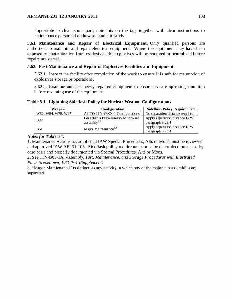
AFMAN91-201 12 JANUARY 2011 103
impossible to clean some part, note this on the tag, together with clear instructions to
maintenance personnel on how to handle it safely.
5.61. Maintenance and Repair of Electrical Equipment. Only qualified persons are
authorized to maintain and repair electrical equipment. Where the equipment may have been
exposed to contamination from explosives, the explosives will be removed or neutralized before
repairs are started.
5.62. Post-Maintenance and Repair of Explosives Facilities and Equipment.
5.62.1. Inspect the facility after completion of the work to ensure it is safe for resumption of
explosives storage or operations.
5.62.2. Examine and test newly repaired equipment to ensure its safe operating condition
before resuming use of the equipment.
Table 5.1. Lightning Sideflash Policy for Nuclear Weapon Configurations
Weapon Configuration Sideflash Policy Requirement
W80, W84, W78, W87 All TO 11N-WXX-1 Configurations1 No separation distance required
B83 Less than a fully-assembled forward
assembly1,2
Apply separation distance IAW
paragraph 5.23.4
B61 Major Maintenance1,3
Apply separation distance IAW
paragraph 5.23.4
Notes for Table 5.1. 1. Maintenance Actions accomplished IAW Special Procedures, Alts or Mods must be reviewed
and approved IAW AFI 91-103. Sideflash policy requirements must be determined on a case-by
case basis and properly documented via Special Procedures, Alts or Mods.
2. See 11N-B83-1A, Assembly, Test, Maintenance, and Storage Procedures with Illustrated
Parts Breakdown; B83-0/-1 (Supplement).
3. ―Major Maintenance‖ is defined as any activity in which any of the major sub-assemblies are
separated.
104 AFMAN91-201 12 JANUARY 2011
Chapter 6
PROTECTIVE CONSTRUCTION AND SPECIFIC EXPLOSIVES FACILITY DESIGNS
Section 6A—Introduction
6.1. General. This chapter contains standards for construction of earth-covered magazines
(ECM), barricaded open storage modules, barricades, ARMCO revetments, substantial dividing
walls, firewalls, and multicube or segregated magazines. Facilities constructed per this chapter:
6.1.1. Are permitted to use reduced separation distance criteria as shown in Chapter 12.
6.1.2. Must meet all the other design criteria of Chapter 5.
6.2. Above Ground Magazines. There are no construction criteria for AGMs other than the
electrical and LPS design criteria in Chapter 5.
6.3. Special Structures. The DDESB has approved reduced NEWQD and reduced QD for
AGM and containers listed in DDESB TP 15, Approved Protective Construction. Use and siting
of these AGM and containers must meet all conditions or restrictions specified in the design and
approval documentation as described in the referenced document.
6.4. High Performance Magazines and Underground Explosives Facilities. See DoD
6055.09-M, DoD Ammunition and Explosives Safety Standards, for information on High
Performance Magazines and underground explosives facilities.
Section 6B—Protective Construction
6.5. Purpose of Protective Construction. Construction features and location are important
safety considerations when planning facilities. Potential explosions’ effects may be altered
significantly by construction features that limit the amount of explosives involved, attenuate
blast overpressure or thermal radiation, and reduce the quantity and range of hazardous
fragments and debris. (Note: Proper location of ES in relation to PES helps minimize
unacceptable damage and injuries in the event of an incident.) The major objectives in facility
planning will be to:
6.5.1. Protect against explosion propagation between adjacent bays or buildings and protect
personnel against death or serious injury from incidents in adjacent bays or buildings. The
construction of separate buildings to limit explosion propagation, rather than the use of either
protective construction or separation of explosives within a single building, shall be
considered when safety would be greatly enhanced or cost would be significantly reduced.
6.5.2. Protect assets, when warranted.
6.6. Requirements for Use of Protective Construction. Hardening an ES or constructing a
PES to suppress explosion effects and provide an appropriate degree of protection may allow a
reduction of the separation distances required by QD tables.
6.6.1. Design of explosion resistant facilities shall be accomplished by an organization or
individual experienced in the field of structural dynamics using design procedures accepted
by professionals in the field. Unified Facilities Criteria (UFC) 3-340-02, Structures to Resist
AFMAN91-201 12 JANUARY 2011 105
the Effects of Accidental Explosions, (formally known as TM-5-1300), is an appropriate
source of effects data and design methods.
6.6.2. Existing, Approved Protective Construction Designs. DDESB TP 15 documents
previously approved protective construction designs. Explosives site plan submissions
utilizing approved protective construction designs shall:
6.6.2.1. Reference the DDESB approval memorandum.
6.6.2.2. Identify the design or drawing numbers used, if available.
6.6.2.3. Specify that the protective construction will be used in the same manner as that
stated in the referenced in the DDESB approval memorandum.
6.6.2.4. State that the structural design has not been altered in any manner that impacts
the design’s integrity or its ability to provide the required level of protection.
6.6.2.5. State that the site specific adaptations of the design have been reviewed and are
appropriate for the site conditions.
6.6.3. Modifications to Previously Approved Protective Construction Designs. For a
protective construction design previously approved by the DDESB, where a structural aspect
of the protective design has been modified by a structural engineer with experience in
designing blast resistant structures, the submitting MAJCOM shall provide:
6.6.3.1. A complete description of the structural modifications made, the reasons for the
modifications, and any explosives safety impact resulting from the modifications.
6.6.3.2. The basis of design and the explosives safety protection being afforded by the
modified design.
6.6.3.3. The following protective construction design and MAJCOM review data:
6.6.3.3.1. For preliminary DDESB approval, concept structural design drawings that
are at least 35 percent complete. For final DDESB approval, the structural design
drawings must be at least 60 percent complete, with all protective construction design
modifications sufficiently developed for validation.
6.6.3.3.2. Design calculations for all critical structural elements.
6.6.3.3.3. All applicable electrical, grounding, and LPS details.
6.6.3.3.4. Supporting blast analyses, experimental data reports, blast design
calculations, and other technical information. Blast analysis and design calculations
must satisfy UFC 3-340-02 requirements.
6.6.3.3.5. A memorandum from the submitting MAJCOM civil engineering office
verifying that the protective construction design modifications comply with DoD
6055.09-M and UFC 3-340-02 requirements. This verification will be based upon a
quality control review (unless a more detailed independent technical review is
warranted based upon either the lack of experience by the designer or the use of a
new, unvalidated blast analysis or design approach) by a competent DoD blast design
agency such as the Naval Facilities Engineering Services Center (NAVFAC ESC) or
the US Army Engineering and Support Center, Huntsville (USAESCH).
AFSC/SEWC will provide appropriate contact information upon request.
106 AFMAN91-201 12 JANUARY 2011
Because both of these organizations operate on a cost reimbursable basis, projects
must arrange payment for these organization’s services.
6.6.4. New Protective Construction Designs. For a new protective construction design, the
submitting MAJCOM shall provide:
6.6.4.1. The criteria being met; a complete description of both the design’s capabilities
and the basis for the design, and the level of explosives safety protection level it affords.
6.6.4.2. The following protective construction design and MAJCOM review data:
6.6.4.2.1. For preliminary DDESB approval, concept structural design drawings that
are at least 35 percent complete. For final DDESB approval, the structural design
drawings must be at least 60 percent complete, with all protective construction design
modifications sufficiently developed for validation.
6.6.4.2.2. Design calculations for all critical structural elements.
6.6.4.2.3. All applicable electrical, grounding, and LPS details.
6.6.4.2.4. Supporting blast analyses, experimental data reports, blast design
calculations, and other technical information. Blast analysis and design calculations
must satisfy UFC 3-340-02 requirements.
6.6.4.2.5. A memorandum from the submitting MAJCOM civil engineering office
verifying that the protective construction design complies with DoD 6055.09-M and
UFC 3-340-02 requirements. This verification will be based upon a quality control
review (unless a more detailed independent technical review is warranted based upon
either the lack of experience by the designer or the use of a new, unvalidated blast
analysis or design approach) by a competent DoD blast design agency such as the
Naval Facilities Engineering Services Center (NAVFAC ESC) or the US Army
Engineering and Support Center, Huntsville (USAESCH). AFSC/SEWC will provide
appropriate contact information upon request. Because both of these organizations
operate on a cost reimbursable basis, projects must arrange payment for these
organization’s services.
6.6.4.3. Once approved, a standard protective construction design can be site-adapted,
provided the conditions and limitations of the DDESB approval are met. The DDESB
will document new standard approved protective construction designs in DDESB TP
15.
Section 6C—Earth-Covered Magazines
6.7. Earth-Covered Magazines. An ECM's primary purpose is to protect AE. To qualify for
the default IMD in Table 12.1, an ECM, acting as an ES, must not collapse. Although
substantial permanent deformation of the ECM may occur, sufficient space should be provided to
prevent the deformed structure or its doors from striking the contents.
6.8. Earth-Covered Magazine NEWQD Limits. ECMs may be approved for storage of up to
500,000 lbs NEWQD of HD 1.1 in accordance with paragraph 12.6.1.
AFMAN91-201 12 JANUARY 2011 107
6.9. Earth-Covered Magazine Design Load Criteria. ECMs must be designed to withstand
the following: (Note: Undefined ECMs must meet the criteria of paragraphs 6.9.1 through 6.9.3
only.)
6.9.1. Conventional (e.g., live, dead, snow) loads for the barrel of an arch-shaped ECM.
6.9.2. Conventional (e.g., live, dead, snow) and blast-induced loads for the roof of a flat-
roofed ECM.
6.9.3. Conventional (e.g., live, dead, snow) loads for the rear wall of an arch-shaped ECM
and for the rear and side walls of a flat-roofed ECM.
6.9.4. Expected blast loads, as applicable:
6.9.4.1. On the head wall and door of 3-Bar ES ECM is a triangular pulse with peak
overpressure of 43.5 psi and impulse of 11.3W1/3
psi-ms.
6.9.4.2. On the head wall and door of 7-Bar ES ECM is a triangular pulse with peak
overpressure of 101.5 psi and impulse of 13.9W1/3
psi-ms.
6.9.4.3. On the roof of a flat-roofed ES ECM is a triangular pulse with peak overpressure
of 108 psi and impulse of 19W1/3
psi-ms.
6.10. Earth-Covered Magazine Earth Cover Criteria.
6.10.1. Earth cover will be reasonably cohesive and free from harmful (toxic) matter, trash,
debris, and stones heavier than ten pounds or larger than six inches in diameter. Solid or wet
clay or similar types of soil will not be used as earth cover because they are too cohesive.
The larger of acceptable stones shall be limited to the lower center of fills and shall not be
used for earth cover over magazines. The earthen material will be compacted and prepared,
as necessary, for structural integrity and erosion control.
6.10.2. If it is impossible to use a cohesive material (e.g., in sandy soil), or where vegetation
growth is ineffective in preventing erosion, the earth cover over ECM will be finished with 2-
3 inches of a suitable material (e.g., geotextiles, gunite, asphalt) that will not produce
hazardous debris, but will ensure structural integrity. The important consideration for these
materials is that they pulverize in the event of an accidental explosion. A mixture combined
with straw, bark, or comparable material would be suitable. Wire mesh may be used in the
finishing material. Aggregate may not be added to the finishing material. Consider means of
validating earth cover depth as part of the design of the finishing material. Reference TM 5-
630, Natural Resources and Land Management, for further information.
6.10.3. Select vegetation for ECM so that their weight or root system will not damage the
structure.
6.10.4. The earth fill or earth cover between ECM may be either solid or sloped. A
minimum of 2 ft of earth cover will be maintained over the top of each ECM. (Note: If the
specified thickness and slope of earth on the ECM is not maintained, the ECM must be sited
as an AGM. Barricaded AGM criteria may be used if the remaining earth cover meets the
barricade criteria of Section 6E.)
6.10.5. See paragraph 5.58.1 for maintenance of earth cover on ECMs.
6.11. Earth-Covered Magazine Drawings.
108 AFMAN91-201 12 JANUARY 2011
6.11.1. DDESB TP 15 provides listings of the various types of ECM that have been
constructed over the years and identifies their structural strength designator (i.e. 7-Bar, 3-
Bar, or Undefined). This reference also lists the 7-Bar and 3-Bar ECM designs that are
currently approved for new construction.
6.11.2. If an ECM's drawing number or numbers are not listed in DDESB TP 15 it will be
treated as an Undefined ECM, until a structural analysis is performed to show that the ECM
qualifies for another structural strength designation, or support documentation is provided to
prove the ECM had been approved by the DDESB with a different structural strength
designation.
6.11.3. For existing, arch-shaped Undefined ECM, U. S. Army Corps of Engineers
(USACE) Report HNDED-CS-S-95-01, Guide For Evaluating Blast Resistance Of
Nonstandard Magazines, may be used to determine if an Undefined ECM could qualify as a
7-Bar or a 3-Bar ECM.
6.11.4. DDESB approval is required prior to any change in an ECM's structural strength
designator.
6.11.5. Certain ECMs have been approved with reduced NEWQD and reduced QD and these
are also listed in DDESB TP 15. Use of these ECMs requires that their use and siting meet
all conditions and restrictions specified in the design and approval documentation, as
described in the referenced document.
6.11.6. New construction of previously DDESB-approved 7-Bar and 3-Bar ECM must meet
the minimum requirements of the current revisions of the approved drawings.
Section 6D—Barricaded Open Storage Modules
6.12. Barricaded Open Storage Modules. Modules allow the same amount of explosives to be
stored using far less land space. However, in the event of an unplanned detonation in a cell, AE
in an adjacent cell will be covered with earth and unavailable for use until extensive uncovering
operations and possibly maintenance are completed. To reduce the MCE expected from an
explosion in one cell, buffered storage arrangements may be used as described in paragraph
12.71.
6.13. Barricaded Open Storage Modules NEWQD and AE Type Limits.
6.13.1. The maximum NEWQD permitted to be stored within each cell is 250,000 lbs.
Normal mixing rules (see paragraph 12.7) apply. HD 1.4 is not additive to the NEWQD.
6.13.2. Storage will be limited to AE that will not promptly propagate explosions or mass
fire between modules, and that are not susceptible to firebrands and fireballs. These
restrictions allow storage at K1.1 separation. Intermagazine (IM) distance for HD 1.2.x. and
1.4 for module to module separation is based on total NEWQD. MCE and Largest Single
Round Net Explosive Weight for Quantity Distance (LSRN) are not used to calculate IM
distance between modules. Only the following AE are approved for modular storage:
6.13.2.1. HE bombs (fuzed or unfuzed, with or without fins), and similarly cased HD 1.1
AE when stored on nonflammable pallets.
6.13.2.2. The below items when contained in nonflammable shipping containers:
AFMAN91-201 12 JANUARY 2011 109
6.13.2.2.1. 30 mm and smaller AE.
6.13.2.2.2. CBU.
6.13.2.2.3. Inert AE components.
6.13.2.2.4. HD 1.4 AE.
6.13.3. Module storage of AE items in flammable outer-packaging configurations will be
minimized. AE items in flammable outer packaging configurations must be covered with fire
retardant material. Combustible dunnage or other flammable material will not be stored
either in, or within, 100 ft of modules.
6.13.4. When fire retardant materials are used to cover AE items stored in modules,
ventilation will be provided between the covers and the stored AE items to minimize the
effects of solar heating upon the stored AE.
6.13.5. AE stored in each module will be limited to one type of item, unless the
MAJCOM/SEW authorizes mixed storage. Mixed storage of high explosive (HE) bombs and
CBUs presents an extreme fragment hazard and should be avoided.
6.14. Barricaded Open Storage Module Design Criteria.
6.14.1. As depicted in Figure 6.1, a module is a barricaded area composed of a series of
connected cells with hard surface (e.g., concrete, packed earth, engineered materials, etc.)
storage pads separated from each other by barricades.
6.14.2. The only restriction on the arrangement of cells within a module and of groups of
modules is that cell openings may not face each other, unless they are either barricaded or
meet QD criteria for an unbarricaded AGM (see Table 12.1).
6.14.3. Although a light metal shed or other lightweight fire retardant cover may be used for
weather protection for individual cells, heavy structures (e.g., reinforced concrete, dense
masonry units) or flammable material will not be used.
6.14.4. Table 6.1 provides the minimum pad sizes necessary to store the NEWQD indicated.
The pad's size may need to be adjusted to accommodate specific AE. This adjustment will
impact the required barricade height (see Table 6.1, Note 3).
6.14.5. Barricade requirements:
6.14.5.1. All barricades used in forming the module will meet the requirements in
Section 6E. The width or length of the stack of AE (controlled by the pad size of the cell)
and the distances between the stack and the top of the barricade influences the minimum
barricade height requirement. The heights listed in Table 6.1 are the minimum
requirement for barricade locations. These minimum heights are based upon both the
storage pad sizes and the separations shown. When feasible, barricade heights shall be
increased (see paragraph 6.16.2).
6.14.5.2. The centerlines of barricades between cells of the module will be located at a
point halfway between adjacent AE storage pads. Back and end (outside) barricades will
be located at the same distance from the pads as those between the cells.
110 AFMAN91-201 12 JANUARY 2011
6.14.5.3. When selecting a site for a module, maximum advantage should be taken of
natural topographical barriers. When used, natural barriers will provide the same level of
protection as the barricade shown in Figure 6.1.
Section 6E—Barricades
6.15. Barricades.
6.15.1. Properly constructed and sited barricades, and undisturbed natural earth have
explosives safety applications for protecting against low-angle fragments. Barricades
provide no protection against high-angle fragments or lobbed AE; some of these high-angle
fragments may travel to the outer limits of protection areas set up for PTR and inhabited
building (IB) distances. If the barricade is destroyed in the process of providing protection,
then secondary fragments from the destroyed barricade must also be considered as part of a
hazards analysis.
6.15.2. To reduce hazards from high-velocity, low-angle fragments, the barricade must be
placed between the PES and the ES so that the fragments of concern impact the barricade
before the ES. The barricade must both be thick enough so that it reduces fragment
velocities to acceptable levels and high enough so that it intercepts the ballistic trajectories of
the fragments of concern.
6.15.3. A barricade must interrupt all direct lines of sight between the ES and PES, and, in
addition, meet the height and length requirements per paragraphs 6.16. and 6.17.
respectively.
6.15.4. Barricades around the exposed site can be used to reduce minimum separations
required by Table 12.1 or fragment distances from 1.2 munitions if tests or engineering
analysis show the barrier will stop the low-angle, high-velocity fragments and the building
will provide protection from the high-angle fragments that can be expected from the PES.
The distance cannot be reduced below that required to provide adequate overpressure
protection to the ES.
6.15.5. A secondary barricade at sites of mission-essential equipment and personnel (such as
wing communications and trim pads) can provide some additional protection; however, high-
angle, low-velocity fragments will still impact the exposed site.
6.15.6. Barricades meeting the requirements of paragraph 6.15.7. may be modified by
substituting a retaining wall for the slope on one side. The slope and thickness of the
retaining wall (preferably of concrete) must ensure a wide enough top to hold the earth firmly
in place.
6.15.7. The slope of an earthen barricade must be two horizontal to one vertical, unless
erosion controls are used. Earthen barricades with slopes no greater than one and one half
horizontal to one vertical that were approved prior to 1976 may continue to be used.
However, renovations to these facilities will meet the above criteria, when feasible.
6.16. Barricade Size and Orientation to Prevent Prompt Propagation Due to High-
Velocity, Low-Angle Fragments. The location, height, and length of a barricade to prevent
prompt propagation due to high-velocity, low-angle fragments shall be determined as follows:
AFMAN91-201 12 JANUARY 2011 111
6.16.1. Location. The barricade may be placed anywhere between the PES and the ES;
however, placing it closer to either the PES or ES will provide slightly greater asset
protection. For AE stacks of different height (elevation), the location shall determine the
barricade 's required height.
6.16.2. Height. To determine the required barricade height:
6.16.2.1. Establish a reference point at the top of the far edge of one of the two AE
stacks between which the barricade is to be constructed. When both stacks are of equal
height, the reference point may be established on either stack. If the tops of the two stacks
are not of equal height (elevation), the reference point shall be on the top of the lower
stack. (NOTE: To preclude building excessively high barricades between AE stacks of
different height (elevation), the barricade should be located as close as possible to the
lower stack (see Figure 6.2.).)
6.16.2.2. Draw a line from the reference point to the highest point of the other stack
(line-of-sight).
6.16.2.3. The barricade's height shall be such that the entire width of the barricade crest
is at least 1 ft [0.3 m] above the line-of-sight as established in paragraph 6.16.2.2.
(NOTE: The barricade height shall be measured at the time of construction as prescribed
in paragraph 6.16.2. If the specified thickness and height of the barricade are not
maintained, the AE stack height shall be reduced as necessary or the AE stacks shall be
resited appropriately. Consideration should be given to making the barricade higher than
required for safety purposes in order to account for accuracy of storage practices
regarding AE stack heights, potential mission changes (requiring higher AE stacks), and
barricade settling/erosion/etc. that could seriously degrade AE storage capability.)
6.16.3. Length. The barricade's length will be determined per Figure 6.2.
6.17. Barricade Size and Orientation for Barricaded ILD Protection. The location, height,
and length of a barricade shall be determined as follows:
6.17.1. Location. The barricade may be placed anywhere between the PES and the ES. The
location shall determine the barricade's required height.
6.17.2. Height. To determine the required barricade height:
6.17.2.1. Establish a reference point at the top of the far edge of one of the two AE
stacks between which the barricade is to be constructed. When both stacks are of equal
height, the reference point may be established on either stack. If the tops of the two stacks
are not of equal height (elevation), the reference point shall be on the top of the lower
stack. (NOTE: To preclude building excessively high barricades, the barricade should be
located as close as possible to the stack on which the reference point was established (see
Figure 6.3.).)
6.17.2.1.1. When the exposed site is not a PES, measure to the top of the ES. If the
ES is an uninhabited PES (i.e., a service magazine), measure to the top of the stack.
If the ES is an inhabited PES (i.e., operating location), measure to the top of the ES.
6.17.2.2. Draw a line from the reference point to the highest point of the other stack.
112 AFMAN91-201 12 JANUARY 2011
6.17.2.3. Draw a second line from the reference point forming an angle of two degrees
above the line.
6.17.3. Length. The barricade 's length shall be determined per Figure 6.3.
6.18. Barricade Size and Orientation for Protection Against Overpressure. General
procedures to predict pressure mitigation versus barricade design and location have not been
developed. However, based on direct-experimental work, the overpressure loading on a surface
area shielded by a barricade is reduced by approximately 50 percent when the following
conditions are met:
6.18.1. Overpressure barricades are only approved for use when placed at the front of 7-
BAR ECMs as an ES and a fragment barricade is placed at the PES.
6.18.2. Location. The barricade’s standoff is within two barricade heights of the protected
area.
6.18.3. Height. The top of the barricade is at least as high as the top of the protected area.
6.18.4. Length. The length of the barricade is at least two times the length of the protected
area.
6.19. Barricade Construction Materials. Materials for earthen barricades will be reasonably
cohesive and free from harmful (toxic) matter, trash, debris, and stones heavier than ten pounds
[4.54 kg] or larger than six inches [152 mm] in diameter. The larger of acceptable stones will be
limited to the lower center of fills. Earthen material will be compacted and prepared, as
necessary, for structural integrity and erosion control. Solid or wet clay or similar types of soil
will not be used in barricades because they are too cohesive. If it is impossible to use a cohesive
material (e.g., in sandy soil) the barricade will be finished with a suitable material (e.g.,
geotextiles, gunite) that will not produce hazardous debris, but will ensure structural integrity.
6.20. Barricade Designs.
6.20.1. DDESB TP 15 lists DDESB-approved designs and construction materials for
barricades. Use of these barricades satisfies barricading criteria.
6.20.2. Alternate barricade designs (e.g., earth filled steel bin) may be approved by the
DDESB provided that testing or analysis demonstrates their effectiveness in stopping high
velocity, low angle fragments.
6.21. Natural Barricades. Natural barricades (e.g., hills) meeting the requirements of this
section are acceptable as barricades. Submit information in the explosives site plan to
demonstrate compliance with barricade design requirements, and include topographical maps of
the terrain.
6.22. Inspection of Barricades. Inspect barricades at least annually to determine the degree of
settling or erosion. MAJCOMs may require more frequent inspection based on environmental
conditions. Barricades finished with a suitable material (e.g., geotextiles, gunite, asphalt) do not
require a depth check as long as there are no signs of the earth fill washing out from underneath
the suitable material. Add fill if a barricade has deteriorated and it no longer provides effective
protection. Also inspect wood riveted barricades and replace rotten timbers or planking.
Maintain barricades so as to prevent erosion or fire hazards. If the magazine’s earth cover erodes
AFMAN91-201 12 JANUARY 2011 113
to less than 2 feet repair as soon as practical (not to exceed 90 days) or classify as an
aboveground unbarricaded magazine.
Section 6F—Earth-Filled, Steel Bin-Type Barricades for Outside Storage
6.23. Earth-Filled, Steel Bin-Type Barricades for Outside Storage.
6.23.1. These barricades, also known as ARMCO, Inc. revetments, are earth-filled steel bins
used to separate AE awaiting scheduled processing (e.g., AE on a flight line associated with
aircraft parking or loading operations; or the temporary positioning of AE awaiting transfer
to preferred, long-term storage). These barricades, which are also used to separate explosive-
loaded aircraft, are normally used to form a series of cells. They are designed to limit the
MCE, for QD siting purposes, of AE properly positioned in separate cells by preventing
prompt detonation transfer to adjacent cells.
6.23.2. When properly sited, these cells prevent prompt detonation transfer; however; all
assets in the series of cells are at risk of loss. Although a revetment is effective in limiting
the blast loading of an adjacent ES to that produced by the largest contents of a single cell,
there is a significant probability that the contents of many of the cells will be damaged or
destroyed by the initial and subsequent fire and explosion events. The extent of such losses
increases with the amount of explosives present.
6.24. ARMCO, Inc. Revetment HD Limits. ARMCO, Inc. revetments cells are approved for
storage of any HD 1.1 and HD 1.2 AE assigned to SG 1 through 4 (as discussed in paragraph
3.22). In addition, storage of HD 1.3, HD 1.4, or HD 1.6 items is approved.
6.25. Types of ARMCO, Inc. Revetments.
6.25.1. Type A revetments, which must be a minimum of 7 feet [2.1 m] thick, can be used to
limit a MCE in a series of cells to the largest quantity in a single cell, provided the quantity in
the single cell does not exceed 30,000 pounds NEW [13,608 kg NEQ].
6.25.2. Type B revetments, which must be a minimum of 5.25 feet [1.6 m] thick, can be
similarly used to limit the MCE, provided no cell contains more than 5,000 pounds NEW
[2,268 kg NEQ].
6.26. Requirements for ARMCO, Inc. Revetments. For ARMCO, Inc. revetments to be used
effectively, the following conditions must be met:
6.26.1. The criteria shown in Figure 6.2.
6.26.2. AE will be positioned no closer than 10 feet [3.1 m] from cell walls, no closer than 3
feet [0.9 m] from the end of the wing walls, and no higher than 2 feet [0.6 m] below the top
of cell walls.
6.26.3. AE will be distributed over the available area within the cell, rather than being
concentrated in a small area.
6.26.4. AE stored in a cell in quantities near the maximum NEW limit will not be configured
into a single row of pallets, stacks, or trailers.
6.26.5. The storage of AE in flammable outer-pack configurations will be minimized.
114 AFMAN91-201 12 JANUARY 2011
6.27. ARMCO, Inc. Revetment Designs. See DDESB TP 15 for ARMCO, Inc. revetment
designs.
Section 6G—Substantial Dividing Walls and Blast Doors
6.28. Substantial Dividing Walls. These walls are one way of separating explosives into
smaller groups to minimize the effects of an explosion and allow a reduction in Q-D separation.
To receive credit as a dividing wall, reinforced concrete walls must either meet Substantial
Dividing Wall criteria or be designed in accordance with the criteria in UFC 3-340-02. These
walls may be used to comply with the compatibility group mixing rules given in Chapter 7
provided the required intermagazine separation distance between the substantial dividing walls
are maintained as discussed below. Note: Dividing walls filled with earth or sand, used to
compartmentalize magazines must be at least 5 feet thick with earth or sand packed between
retaining walls. Sand-bag type dividing walls will be at least 5 feet thick, except where approved
for other uses as in TO 11N-20-7. See DDESB TP 15, Approved Protective Construction, for all
storage requirements.
6.28.1. Definition of an SDW. An SDW is a reinforced concrete wall having the
following characteristics: (Note: Existing 12-inch reinforced concrete walls originally
constructed for explosives operations, explosives storage, or remotely controlled
explosives operations are considered adequate for meeting requirements listed in
6.28.1.1. through 6.28.1.6. only)
6.28.1.1. A minimum thickness of 12 inches.
6.28.1.2. A minimum steel reinforcing bar size of ½-inch (0.50) diameter (#4).
6.28.1.3. Steel reinforcing bars are spaced not more than 12 inches on center horizontally
and vertically, on both faces of the wall, with bars on one face staggered with the bars on
the opposite face.
6.28.1.4. Concrete cover over the steel reinforcing bars in approximately 2 inches thick.
6.28.1.5. Concrete has a minimum compressive strength of 2,500 pounds per square inch
(psi).
6.28.1.6. SDW main steel is continuous into supports as follows:
6.28.1.6.1. If the SDW is used for prevention of either prompt detonation or
propagation of burning reactions, it must, at a minimum, be adequately supported at
the floor.
6.28.1.6.2. If the SDW is used for personnel protection, from either detonation or
burning reactions, for remotely-controlled operations, it must, at a minimum, be
adequately supported on at least two sides (e.g., the SDW is supported at the floor and
with at least one adjacent SDW.
6.28.2. When an SDW described above is incorporated into a room or cubicle, additional
structural considerations must be addressed in order to limit internal pressure build-up within
the room or cubicle and assure the capability of the SDW to provide prompt propagation
protection to munitions in adjacent rooms or cubicles. For this reason, the following
additional criteria apply to a room or cubicle incorporating one or more SDW:
AFMAN91-201 12 JANUARY 2011 115
6.28.2.1. A minimum of two surfaces (wall or roof) of the room or cubicle must be open
and frangible. A surface is considered frangible if its unit weight < 10 lbs/ft2. If a roof is
treated as one of the frangible surfaces, then any potential additional dead load must be
considered when calculating the roof’s unit weight. In areas where the design ground
snow load, pg, in ASCE 7, ―Minimum Design Loads for Buildings and Other Structures‖
(latest version) or UFC 3-310-01, ―Structural Load Data,‖ exceeds 20 lbs/ft2, the
calculation of a roof’s unit weight must include consideration of potential snow load. To
avoid undue conservatism, the snow load contribution to a roof’s unit weight may be
taken as 42% of the average roof design snow load, calculated in accordance with ASCE
7.
6.28.2.2. A minimum scaled vent area (Av/V2/3
) of 1.85 will be provided; where Av =
total area of frangible and open surfaces (ft2) and V = volume of room (ft
3).
6.28.2.3. When used as a firewall for prevention of propagation of burning reactions, the
SDW must be continuous from the floor to the roofline to mitigate thermal effects unless
otherwise required by local fire codes to extend above the roof. When used to prevent a
prompt detonation reaction, the SDW must be at least two feet higher than the AE stacks
on either side of the SDW.
6.28.2.4. Those rooms or cubicles containing only materials that are expected to exhibit
burning reactions will have adequate venting area; that is, a frangible wall or roof.
6.28.3. Application and use of SDW for prevention of prompt detonation or propagation of
burning reactions. The following conditions apply to the use of SDW for the prevention of
prompt detonation or propagation of burning reactions. When these conditions are not met,
individual NEWQD of each room or cubicles will be summed together and QD will be based
on the summed NEWQD.
6.28.3.1. To prevent a prompt detonation reaction in any acceptor room or cubicle
separated by an SDW from adjacent donor rooms or cubicles, each adjacent donor room
or cubicle containing material that will detonate is limited to a maximum of 425 pounds
NEWQD or to a loading density (NEWQD/room volume (ft3)) of < 0.20 pounds/ft
3,
whichever is attained first. Each adjacent donor room or cubicle containing HD 1.2.1
material is limited to a maximum NEWQD of 5,000 pounds, and to a maximum credible
event (MCE) of 425 pounds or a loading density of (MCE/room volume (ft3)) of < 0.20
pounds/ft3, whichever is attained first. Each adjacent donor room or cubicle containing
HD 1.2.2 material is limited to a maximum NEWQD of 5,000 pounds. Each adjacent
donor room or cubicle containing HD 1.2.3 material is limited to a maximum NEWQD of
5,000 pounds, and to a largest single item NEWQD of 425 pounds or a loading density of
(largest single item NEWQD/room volume (ft3)) of < 0.20 pounds/ft
3, whichever is
attained first. For HD 1.1 and HD 1.2.1 located in acceptor rooms or cubicles, storage is
limited to SG 1, 2, 3, and 4 AE only. HD 1.1 and HD 1.2 AE will be placed no closer
than 3 feet from the nearest wall.
6.28.3.2. To prevent a prompt detonation reaction involving SG 5 in an acceptor room or
cubicle separated by an SDW from adjacent donor rooms or cubicles, each adjacent
donor room or cubicle containing material that will detonate is limited to a maximum of
20 pounds NEWQD, or to a loading density (NEWQD/room volume (ft3)) of < 0.01
pounds/ft3, whichever is attained first. Each adjacent donor room or cubicle containing
116 AFMAN91-201 12 JANUARY 2011
HD 1.2.1 material is limited to a maximum NEWQD of 5,000 pounds, and to an MCE of
20 pounds or a loading density of (MCE/room volume (ft3)) of < 0.01 pounds/ft
3,
whichever is attained first. Each adjacent donor room or cubicle containing HD 1.2.2
material is limited to a maximum NEWQD of 5,000 pounds. Each adjacent donor room
or cubicle containing HD 1.2.3 material is limited to a maximum NEWQD of 5,000
pounds, and to a largest single item NEWQD of 20 pounds or a loading density of
(largest single item NEWQD/room volume (ft3)) of < 0.01 pounds/ft
3, whichever is
attained first. HD 1.1 and HD 1.2 AE will be placed no closer than 3 feet from the
nearest wall.
6.28.3.3. To prevent propagation of a burning reaction (i.e., HD 1.3) between adjacent
rooms or cubicles separated by an SDW, the NEWQD in each room or cubicle is limited
to 5,000 pounds of packaged materials or 300 pounds for unpackaged materials. No
standoff distance from the wall is required for HD 1.3.
6.28.3.4. When HD 1.2 and HD 1.3 are mixed together within a room or cubicle, their
combined NEWQD shall be restricted to 5,000 pounds packaged or 300 pounds
unpackaged. The MCE for HD 1.2.1 and the largest single item NEWQD for HD 1.2.3
shall comply with the paragraphs above.
6.28.3.5. Mission essential quantities of HD 1.4 located in donor or acceptor rooms or
cubicles do not affect the prevention of a prompt detonation reaction or propagation of a
burning reaction. No standoff distance from the wall is required for HD 1.4.
6.28.4. Application and use of SDW for personnel protection during remotely controlled AE
operations. The following apply to the use of SDW for personnel protection during remotely
controlled AE operations:
6.28.4.1. Personnel will be separated from operations involving materials that will
detonate either by the shorter K24 separation distance when measured over or around an
SDW or by the shortest distance that provides 2.3-psi level of protection to personnel.
For HD 1.1, the NEWQD shall be used; for HD 1.2.1, the MCE shall be used; for HD
1.2.2, an NEWQD of 1.6 pounds shall be used; for HD 1.2.3, the largest single item
NEWQD shall be used.
6.28.4.2. Personnel will be separated from operations involving only material where a
burning reaction is expected by the shorter K8 separation distance when measured over
or around an SDW or by the shortest distance that limits the thermal flux to personnel to
0.3 calories/cm2/sec.
6.28.4.3. Personnel will be protected from fragments and debris having energies of 58
foot-pounds or greater (hazardous fragments). An SDW that is properly supported on
two sides (such as a reinforced concrete floor and another SDW) will provide such
personnel protection from a maximum credible event involving up to 300 pounds of AE
expected to burn or up to 8 pounds of AE expected to detonate. The maximum credible
event for HD 1.1 shall be the NEWQD; for HD 1.2.1, the MCE shall be used; for HD
1.2.3, the largest single item NEWQD shall be used. (Note: For HD 1.2.2, the maximum
credible event is less than 8 pounds, by definition.)
6.28.5. If any of the SDW criteria discussed above cannot be met, then the wall or room
design and explosives scenario will be separately analyzed to determine if equivalent
AFMAN91-201 12 JANUARY 2011 117
protection is provided by the available wall or room arrangement (e.g., a four wall cubicle, an
alternate reinforced concrete wall design, a larger room, a greater standoff, or a smaller
quantity of SG 5). The engineering analysis must address the specific conditions according
to UFC 3-340-02 criteria to determine the proper wall construction or explosives weight and
spacing limitations. DDESB approval is required for any analysis performed.
6.28.6. Intraline distance (ILD) level of protection is not addressed by this section. The
requirement remains K18 or ILD, as specified in the appropriate tables for the HD in
question. Presently, there is no consideration that an SDW or any type of wall provides an
equivalent ILD level of protection. However, if an SDW is determined to provide the
required personnel protection from a remotely controlled operation, then by default, it can be
assumed that K18 protection is also provided by that SDW. Refer to UFC 3-340-02 and Mil-
Std 398, Shields, Operational for Ammunition Operations, Criteria for Design and Tests for
Acceptance, for personnel protection standards.
6.28.7. For special weapons, the criteria in TO 11N-20-7, Nuclear Safety Criteria, when
more restrictive, will be the limiting factor and override the above criteria.
6.28.8. The provisions of paragraph 4.19 apply.
6.29. Blast Doors. Blast Doors may be required for openings through SDWs. When required,
design these doors to be at least equal in strength to the SDW. See UFC 3-340-02 for design
factors for new structures. Take care to ensure these doors are not installed as a matter of
convenience. Avoid blast doors when a continuous SDW would not unnecessarily interfere with
operations.
Section 6H—Multicube or Segregated Magazines
6.30. Multicube or Segregated Magazines. See Section 6G for guidance. If the NEWQD
limit is exceeded in any one cell, compatibility must be maintained throughout the facility and
the total NEWQD of all cells is used to compute QD requirements. See paragraph 12.7 for rules
when combining mass detonating with non-mass detonating explosives.
6.30.1. See paragraph 12.7 for determining MCE. When using the provisions in this
paragraph, each cell may be considered a separate facility with equivalent IM distance
between cells, for determining NEWQD in QD calculations.
6.30.2. A substantial dividing wall that is continuous from the floor to the roofline, unless
otherwise required by local fire codes to extend above the roof, may be used to meet
equivalent HD 1.3 intermagazine protection for 5,000 pounds of packaged (shipping or
transportation configuration) or 300 pounds of unpackaged HD 1.3 materials.
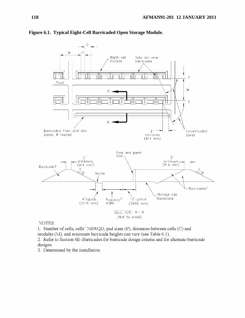
118 AFMAN91-201 12 JANUARY 2011
Figure 6.1. Typical Eight-Cell Barricaded Open Storage Module.
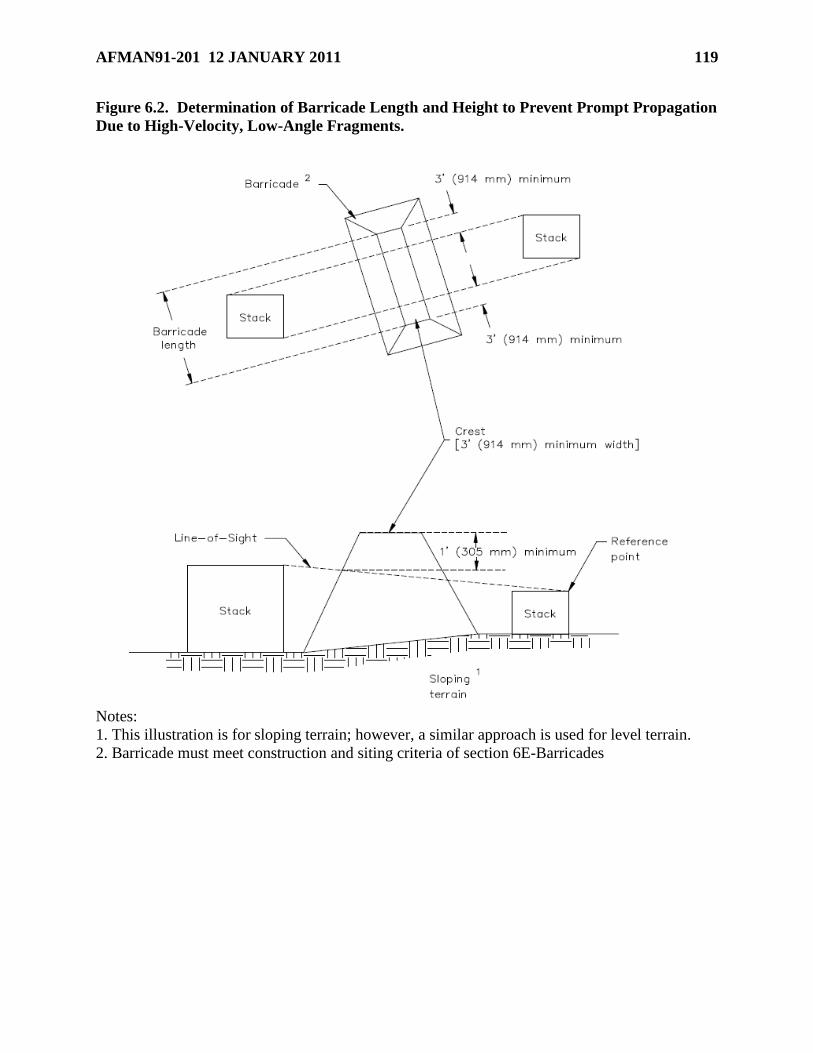
AFMAN91-201 12 JANUARY 2011 119
Figure 6.2. Determination of Barricade Length and Height to Prevent Prompt Propagation
Due to High-Velocity, Low-Angle Fragments.
Notes:
1. This illustration is for sloping terrain; however, a similar approach is used for level terrain.
2. Barricade must meet construction and siting criteria of section 6E-Barricades
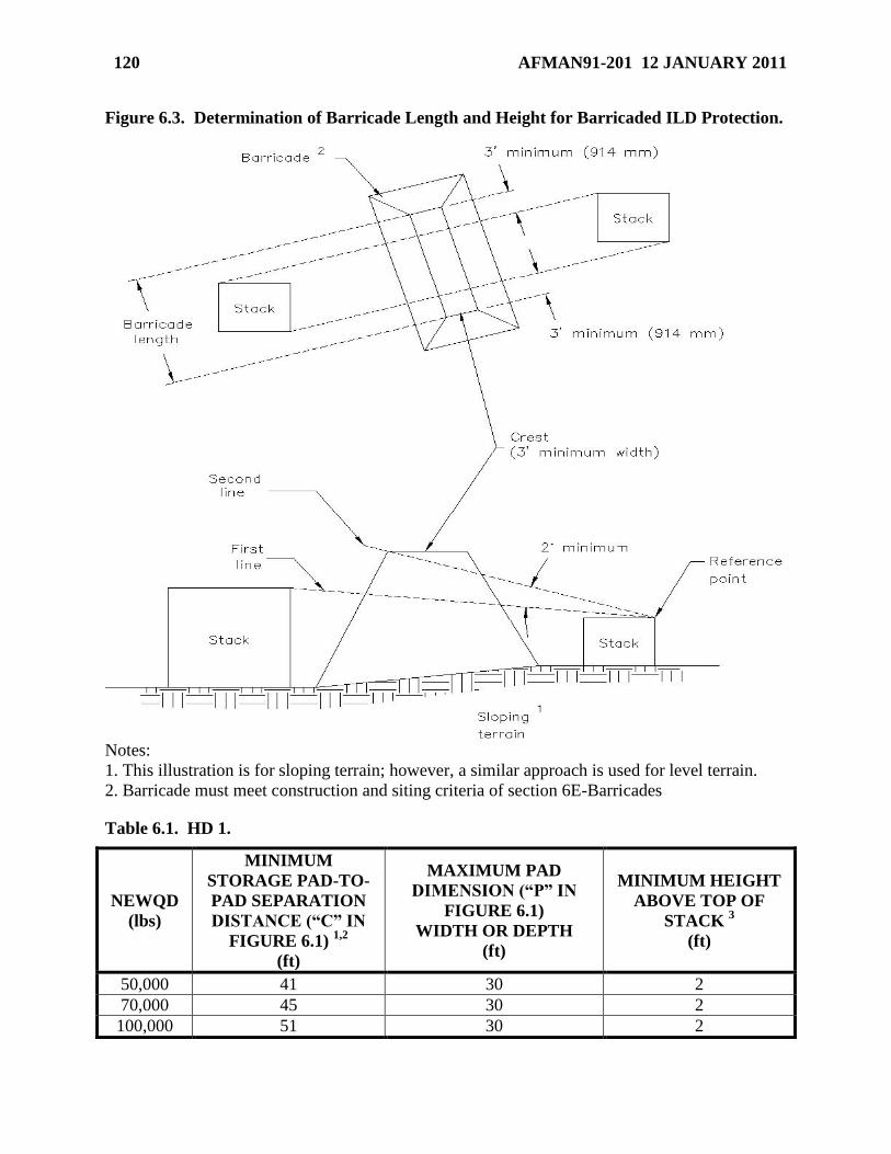
120 AFMAN91-201 12 JANUARY 2011
Figure 6.3. Determination of Barricade Length and Height for Barricaded ILD Protection.
Notes:
1. This illustration is for sloping terrain; however, a similar approach is used for level terrain.
2. Barricade must meet construction and siting criteria of section 6E-Barricades
Table 6.1. HD 1.
NEWQD
(lbs)
MINIMUM
STORAGE PAD-TO-
PAD SEPARATION
DISTANCE (―C‖ IN
FIGURE 6.1) 1,2
(ft)
MAXIMUM PAD
DIMENSION (―P‖ IN
FIGURE 6.1)
WIDTH OR DEPTH
(ft)
MINIMUM HEIGHT
ABOVE TOP OF
STACK 3
(ft)
50,000 41 30 2
70,000 45 30 2
100,000 51 30 2
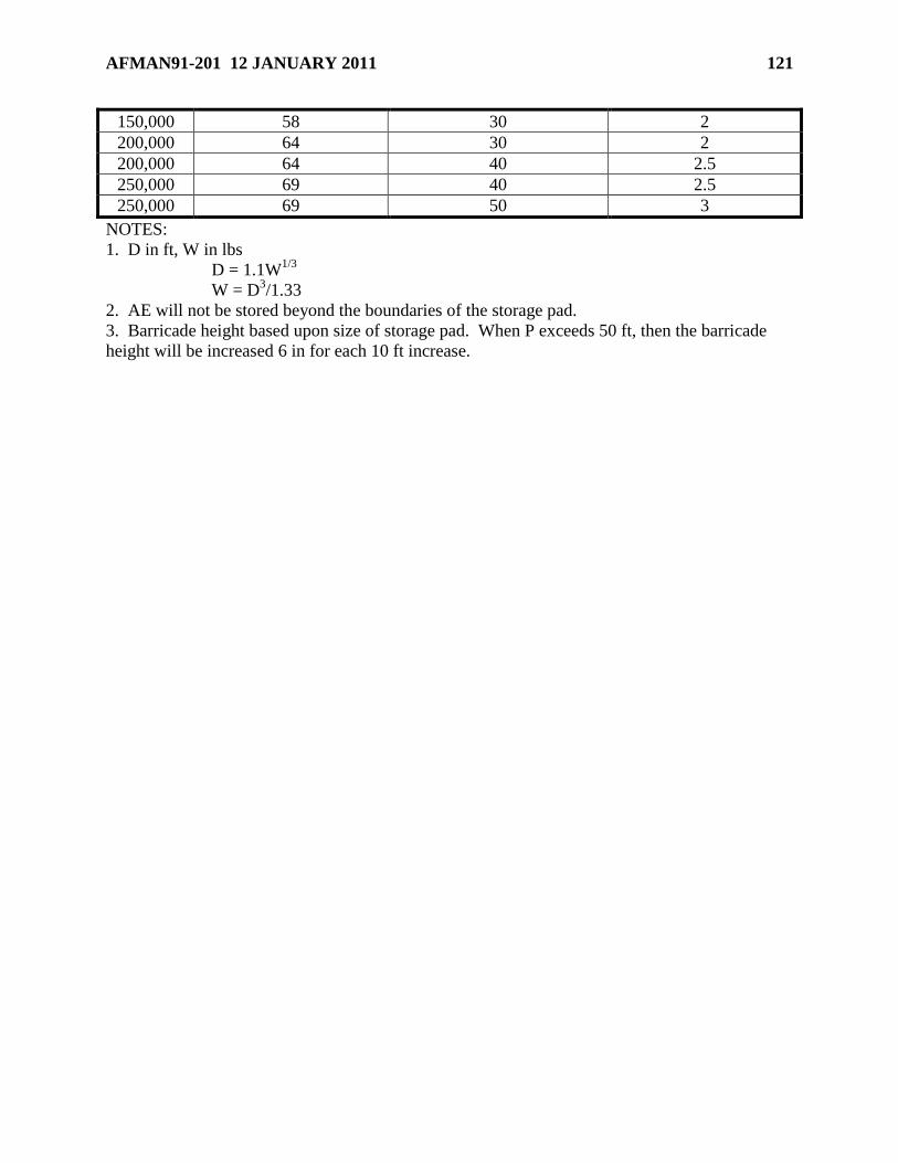
AFMAN91-201 12 JANUARY 2011 121
150,000 58 30 2
200,000 64 30 2
200,000 64 40 2.5
250,000 69 40 2.5
250,000 69 50 3
NOTES:
1. D in ft, W in lbs
D = 1.1W1/3
W = D3/1.33
2. AE will not be stored beyond the boundaries of the storage pad.
3. Barricade height based upon size of storage pad. When P exceeds 50 ft, then the barricade
height will be increased 6 in for each 10 ft increase.
122 AFMAN91-201 12 JANUARY 2011
Chapter 7
EXPLOSIVES OPERATIONS AND STORAGE
Section 7A—Introduction
7.1. Introduction. This chapter provides general information about explosives and safety
requirements for operations involving explosives and explosives storage requirements, to include
compatibility principles and mixed compatibility storage. The absence of specific guidance on a
particular explosives operation does not imply that safeguards are not applicable.
Section 7B—Locally Written Instructions
7.2. Locally Written Instructions. All explosives operations must be conducted in accordance
with written instructions. Item TOs generally fulfill this requirement, but may not address all
local conditions. Locally written instructions may be required to address the items in paragraph
7.3. Locally written instructions may take the form of crew briefings, safety briefings, local
operating instructions, etc. The items in paragraph 7.3 may be addressed by one or more of these
methods.
7.2.1. Locally written instructions will be:
7.2.1.1. Approved by the squadron commander or equivalent.
7.2.1.2. Coordinated with the weapons safety office and all other involved organizations.
7.2.1.3. Available at the work site.
7.2.1.4. Written in the language workers understand.
7.2.1.5. Briefed to all workers prior to beginning an explosives operation. Ensure
workers understand the instructions prior to beginning the operation.
7.2.2. Locally written instructions are not required for EOD emergency operations in
connection with approved render safe procedures.
7.2.3. Locally produced checklists and work cards concerning nuclear operations require
approval according to TO 00-5-1, Air Force Technical Order System.
7.2.4. Locally produced operating instructions will be developed and processed according to
AFI 33-360, Publications and Forms Management.
7.3. Contents of Locally Written Instructions. Include the following information, as
applicable, in locally written instructions. The MAJCOM will determine if additional items are
required.
7.3.1. Personnel limits (see paragraph 7.5.).
7.3.2. Explosives limits, including HD and CG of the explosives involved (see paragraph
7.6.).
7.3.3. Exact locations where operations will be done.
AFMAN91-201 12 JANUARY 2011 123
7.3.4. Safety requirements, to include special requirements for personal protective clothing
and equipment.
7.3.5. Step-by-step procedures for doing the task (refer to specific steps in the TO for
applicable portions of the operation).
7.3.6. Actions to be taken during an emergency.
Section 7C—General Requirements for Operations Involving Explosives
7.4. Personnel Qualifications. Personnel who work with explosives will be trained in
accordance with AFI 91-202, The US Air Force Mishap Prevention Program, and qualified in
the tasks to be performed. They must understand all safety standards, requirements, and
precautions that apply to the operation. The supervisor must be knowledgeable of all hazards
involved in the operation, convey emergency procedures to workers, casuals, and visitors, and
maintain strict housekeeping standards. The supervisor must also know what steps to take when
abnormal conditions arise.
7.5. Personnel Limits. Design explosives operations to ensure minimum exposure of personnel
to explosives, in compliance with the cardinal principle (see paragraph 1.1.2). Supervisors are
responsible for enforcing personnel limits.
7.5.1. Buddy System. Good industrial safety practices may dictate use of the buddy system
even though only one person may be required to perform the work. Use of the buddy system
does not violate the cardinal principle.
7.5.2. EOD Procedures. Performance of EOD procedures requires a minimum of two
EOD-qualified people (one worker and one for safety back-up and to detect errors in
procedures). If sent on a mission where performance of EOD procedures is likely, use a
minimum of two EOD-qualified people. One EOD-qualified person (with an appropriate
safety back-up capable of rescue actions) can provide site assessments, evaluations, and other
on-site analysis as long as no procedures are performed and ordnance or explosives are not
disturbed.
7.5.3. Casuals. Casuals are persons not normally part of an explosives operation but have
duties that require their presence, such as quality assurance, medical, safety or inspection
personnel. Note: When conducting intentional detonation operations,(e.g., EOD operations,
range clearance, or other demolition and munitions destruction) emergency medical support
must be available within 30 minutes while the operations are being performed. The medical
support must be analogous to the expected trauma resulting from an accident.
7.5.4. Visitors. Visitors are non-essential personnel with limited access. Stop operations
when visitors are present.
7.5.5. Posting Personnel Limits. Clearly post personnel limits for the operations being
conducted at each explosives operating location. Posted limits will distinguish between
supervisors, workers, and casuals. Locally written instructions containing personnel limits
will suffice in lieu of posting.
7.5.5.1. Do not post personnel limits at aircraft parking locations, even if used for
uploading or downloading explosives.
124 AFMAN91-201 12 JANUARY 2011
7.5.5.2. Do not post personnel limits at storage locations or licensed explosives storage
locations.
7.6. Explosives Limits. Design explosives operations to ensure minimum exposure of
personnel to explosives in compliance with the cardinal principle (see paragraph 1.1.2). Only
the explosives needed to ensure a safe and efficient work flow will be present in an operating
location when operations are being conducted; this should normally be limited to a one day
supply. Attempt to comply with compatibility group mixing requirements (see Section 7K), if
possible, to minimize the likelihood and severity of a mishap. Supervisors are responsible for
enforcing explosives limits.
7.6.1. Posting Explosives Limits. Clearly post the authorized HD and NEWQD at all
explosives locations, to include MCE for HD 1.2.1, NEWQD of the largest single round for
HD 1.2.3, and (xx) for HD 1.2.3. A properly displayed explosives license (see Chapter 11)
fulfills this requirement for licensed explosives storage locations. For all other explosives
storage locations, locally written instructions (see Section 7B) containing authorized HD and
NEWQD will suffice if posting is impractical. Locally written instructions containing HD
and NEWQD will suffice in lieu of posting for all explosives operating locations.
7.6.2. Posting Operating Limits. For explosives operating locations, clearly post the HD
and NEWQD limits (to include MCE for HD 1.2.1, NEWQD of the largest single round for
HD 1.2.3, and (xx) for HD 1.2.3) for the operation being conducted, if less than the
authorized explosives limits. These limits may be expressed in terms of the specific
explosives items, such as ―two AIM-9 missiles.‖ Locally written instructions (see Section
7B) containing HD and NEWQD will suffice in lieu of posting.
7.7. Housekeeping. The following are minimum precautions:
7.7.1. Non-explosives Waste Materials.
7.7.1.1. Do not commingle non-explosives waste materials (e.g., oily rags, combustible
scrap, wood, paper, and flammable packing materials) with explosives residue.
7.7.1.2. Place non-explosives waste materials in approved, properly marked containers.
7.7.1.3. Place non-explosives waste material containers outside of explosives facilities,
except for containers required at work locations during operations.
7.7.1.4. Empty non-explosives waste material containers at working locations as often as
needed, but at least once each workday or shift.
7.7.1.5. Contact the base environmental management office for additional guidance for
hazardous materials.
7.7.2. Explosives Residue.
7.7.2.1. Provide grounded, covered, self-closing containers for explosives residue and
materials containing explosives residue (e.g., rags, clothing).
7.7.2.2. Cover explosives residue and waste materials containing explosives residue with
water or oil, if this does not add to the hazard. Number 10 mineral oil is useful for
covering pyrotechnic, tracer, flare, and similar mixtures. If using water, immediately
immerse the items to reduce production of dangerous gases.
AFMAN91-201 12 JANUARY 2011 125
7.7.2.3. Remove explosives residue and materials containing explosives residue at
frequent intervals and before leaving at the end of the duty day or shift. Place in the
disposal area or an isolated temporary collection point.
7.7.2.4. When using isolated temporary collection points, set up time and quantity limits
to ensure timely movement of collected material to the disposal area. Do not store
collected material in the disposal area.
7.7.2.5. Dispose of explosives residue and materials containing explosives residue in
accordance with environmental standards and locally written instructions (see Section
7B) approved by the base environmental management office.
7.7.3. Cleaning Compounds.
7.7.3.1. Do not use cleaning compounds containing wax or oil on conductive floors or
surfaces.
7.7.3.2. Do not use cleaning agents that include caustic alkalis in locations containing
explosives residue (sensitive explosives compounds may be formed).
7.7.3.3. Remove explosives residue in accordance with the item TO.
7.7.3.4. Use non-abrasive cleaning compounds; such compounds are often combustible
but not volatile. Closed cup flash point of cleaning compounds must not be less than
230o F.
7.8. Smoking. AFOSH 91-100, Aircraft Flight Line - Ground Operations and Activities,
Chapter 1, governs smoking on the flightline. For all other explosives locations, the following
requirements apply:
7.8.1. Allow smoking in an explosives storage area or operating location only in specifically
designated locations, where ―authorized smoking areas‖ signs are posted.
7.8.2. A ―No Smoking Except in Designated Areas‖ or ―No Smoking‖ sign will be posted at
each entrance to an explosives storage area.
7.8.3. In an explosives storage area or operating location containing exposed explosives,
include a notice that flame-producing devices must be turned over to the entry controller or
placed in a container provided.
7.8.4. Requirements for Designated Smoking Locations.
7.8.4.1. Do not place within 50 feet of any explosives locations (to include conveyances
or material handling equipment loaded with explosives items).
7.8.4.2. Coordinate proposed location with weapons safety, and obtain installation fire
chief or delegate approval. Approval will address whether a fire extinguisher must be
available. Display a certification of approval in each designated smoking location.
7.8.4.3. Provide suitable self-closing or self contained properly marked receptacles for
extinguishing smoking materials.
7.8.4.4. Provision of an electrical push-button type lighter that cuts off when pressure is
released, or when the lighter tips over, is recommended.

126 AFMAN91-201 12 JANUARY 2011
7.8.4.5. Persons wearing clothing contaminated with flammables, explosives or other
hazardous materials are not allowed in designated smoking areas.
7.8.5. Do not smoke in, on, or within 50 feet of any conveyance or material handling
equipment loaded with explosives items.
7.9. Handling of Explosives. This paragraph applies to the handling of explosives and
movement of explosives within the immediate vicinity of an explosives operation.
7.9.1. Only trained personnel under the supervision of an individual who understands the
hazards and risks involved in the operation are to handle explosives.
7.9.2. Handle detonators, initiators, squibs, and other such electrically or mechanically
initiated devices in protective containers during storage, transportation, and inspection. Use
containers designed to prevent item-to-item contact. Mark to identify the contents.
7.9.3. Do not use bale hooks to handle explosives.
7.9.4. Do not use nails to secure covers or make repairs on explosives containers unless there
is no hazard to the explosive item or danger of penetrating protective coverings. Exercise
special care when using pneumatic- or cartridge-activated nail guns (see AFI 21-201,
Conventional Munitions Maintenance Management).
7.9.5. Do not tumble, drag, drop, throw, roll, or ―walk‖ munitions. Containers designed with
skids may be pushed or pulled for positioning.
7.9.6. Do not roll un-palletized conventional high explosive bombs or other explosives
unless authorized by the item TO and lugs or other projections have been removed or if they
are protected by dunnage rails.
7.9.7. Do not use conveyors, chutes, hand trucks, or forklifts in atmospheres and locations
where they will create hazards.
7.9.8. Interlock and support sections of roller conveyors used to move explosives. Do not
use boxes containing explosives or munitions to support conveyors.
7.9.9. Always consider vehicle and handling equipment type, type of load, and prevailing
weather and surface conditions when determining if safe movement is feasible.
7.9.10. Restraining devices designed for use with vehicle and handling equipment will be
used in accordance with applicable TOs.
7.9.11. Do not move explosives rapidly across any non-conductive surface.
7.10. Portable Equipment.
7.10.1. Ensure portable electronic equipment introduced to a hazardous location meets the
requirements of paragraph 5.4.
7.10.2. UL-listed floodlight systems, mounted on heavy portable stands and placed outside
the magazine door or the outdoor working area, may be used where required. Service cords
must be placed or protected so that they cannot be walked on or run over by equipment.
7.10.3. Flexible cords should be type SO hard service cord. Splices are not allowed. All
flexible cords, receptacles, and attachment plugs must be equipped with three prongs so that
the third prong (green wire) acts as ground. Place or protect each electrical cord so that it
AFMAN91-201 12 JANUARY 2011 127
cannot be walked on or run over by equipment. Flexible cords will not be used in place of
fixed or installed electrical wiring. Damaged flexible cords will be immediately removed
from service.
Section 7D—Static Grounding
7.11. Static Electricity. Static electricity is created when two different materials come in
contact and then are separated again; this includes when the two materials are rubbed against
each other. Separated charges accumulate on the two materials, creating a voltage potential that
can be discharged when either of the materials is moved close to an uncharged or grounded
object. This discharge can cause a mishap if it occurs through, or in the presence of, a hazardous
substance susceptible to electrostatic initiation. For this reason, precautions shall be taken
against performing unnecessary actions that lead to the buildup of static voltages, actions shall be
taken to avoid the prolonged storage of static voltages on personnel or equipment, and actions
shall be taken to discharge static voltages in a safe and controlled manner during operations
involving explosives. See Section 5E for the static grounding and bonding system design and
inspection requirements.
7.12. Requirement for Static Grounding. See paragraph 7.15 for static grounding techniques
and paragraph 7.16 for methods to reduce the buildup of static electricity. Static grounding is
required for:
7.12.1. Personnel, equipment, and explosives, when the responsible engineering function has
determined grounding is necessary for specific maintenance or electrical test operations;
grounding requirements will normally be included in the item TO.
7.12.2. Weapons systems in storage as required in the item TO.
7.12.3. Personnel and equipment in hazardous locations (see Section 5C).
7.12.4. Personnel handling EEDs (see Electro-Explosive Device in Attachment 1). Note:
Always avoid directly touching an electrical primer. See paragraph 7.13 for static grounding
requirements for handling unpackaged EEDs.
7.12.5. Personnel handling exposed explosives (see exposed explosives in Attachment 1);
this does not apply to C-4.
7.12.6. Explosive components which incorporate an electrical initiating system when
undergoing maintenance; assembly to, or disassembly from, an all-up-round (AUR)
configuration; or electrical connection or disconnection. Note: Unless required by TO, static
grounding is not required when replacing components of AURs which incorporate an
electrical initiating system when the replacement operation does not require electrical
connection or disconnection.
7.12.7. Aircraft, when explosives are being loaded or unloaded, as required in paragraph
7.14.
7.13. Static Grounding for Handling Unpackaged EEDs. When EEDs are unpackaged and
handled follow item TO requirements for static grounding and comply with the following:
7.13.1. Personnel must periodically ground themselves. Post signs at entrances and in the
room reminding personnel that periodic grounding is required, except where compliance
128 AFMAN91-201 12 JANUARY 2011
would create any additional personnel safety hazard. Install one or more static grounding
bars or device (see paragraph 5.12.2) and require personnel to touch the grounding device
before handling the EED and at frequent intervals while working to discharge any static
potential.
7.13.2. Where feasible, comply with paragraphs 7.15.1.1 and 7.15.1.3.
7.13.3. Adhere to the precautions in paragraph 7.16.
7.13.4. Every person who handles exposed EED’s must be careful not to allow the EED’s
electrical contacts to touch any of the metal surfaces of aircraft and missile skin or structure.
Additionally, the handler must actively take precautions against allowing the build up or
discharge of static electric energy through the EED’s electrical contacts.
7.14. Static Grounding for Aircraft During Explosives Loading and Unloading. Combat
and cargo aircraft will be grounded during explosives loading or unloading operations, except as
noted in paragraphs 7.14.1 and 7.14.2. See TO 00-25-172, Ground Servicing of Aircraft and
Static Grounding/Bonding and applicable aircraft TO for grounding procedures. Personnel
handling the explosives will equalize their static electrical potential to that of the aircraft, vehicle
or handling equipment, before beginning operations and at frequent intervals thereafter to
discharge any static buildup. Ensure the aircraft being loaded or unloaded is not within the
hazard zone of any operating transmitters (see Chapter 9).
7.14.1. Cargo aircraft do not require grounding during engine running on/off (ERO)
operations.
7.14.2. Grounding of aircraft during explosives loading or unloading is recommended but
not required where there are unusual parking problems in operating from bare or limited
bases, nonmilitary airfields, host nation airfields, etc. This exception does not relieve
commands from responsibility for providing proper grounding in locations where operations
continue or where parking facilities are required on a recurring basis. Where static
grounding facilities are not available at a suitable parking location, commands should use the
best alternate method of reducing the hazard in the following order or precedence:
7.14.2.1. Keep static grounding to 10,000 Ohms or less by using ground rods.
7.14.2.2. Equalize the static electrical potential between the aircraft and the vehicle or
handling equipment used in loading or unloading by bonding them together with an
approved static ground wire, cable, or strap (see paragraph 5.14). Note: It might not be
feasible to bond the handling equipment to the aircraft if the handling equipment must
move during the operation.
7.15. Static Grounding Techniques. In the absence of TO guidance, this paragraph provides
techniques for accomplishing static grounding (see paragraphs 5.13 through 5.15 for further
guidance).
7.15.1. Protective clothing is not a substitute for personnel static grounding. Static
grounding of personnel will be accomplished by any of the following:
7.15.1.1. Through the use of wrist-straps connected to the facility ground.
7.15.1.2. By periodically touching a grounded surface (such as an airframe) or a
grounding bar.
AFMAN91-201 12 JANUARY 2011 129
7.15.1.3. By wearing conductive footwear on conductive floors, mats or runners (see
Section 5F), if the floor, mat, or runner is properly grounded.
7.15.2. Static grounding of equipment will be accomplished by any of the following:
7.15.2.1. Through the use of a static ground wire, cable, or strap (see paragraph 5.14)
between the item to be grounded and the facility ground.
7.15.2.2. By using conductive tabletops, or conductive material coverings on the
tabletop, if the conductive surface or material is properly grounded.
7.15.3. When making a grounding connection, attach the ground wire, cable, or strap to the
item requiring grounding first, then connect the other end of the ground wire, cable, or strap
to the approved facility grounding system. This ensures that if a spark occurs, it will occur at
the connection to the facility grounding system instead of at the item.
7.15.3.1. If the existing static grounding or bonding reels were permanently attached to
the facility ground when installed, a temporary grounding connection using an additional
cable should be made first (when possible) following the procedure in paragraph 7.15.3
before connecting the item to the permanent system.
7.15.3.2. When static grounding or bonding reels are installed, either in new or existing
facilities, do not permanently attach them to the facility grounding system.
7.15.4. When a different or new ground is needed for an item, always make the new ground
connection first (in the same manner as described in paragraph 7.15.2) before disconnecting
the existing ground connection (make-before-break grounding). This ensures that the item
will be grounded at all times while transitioning from one ground connection to another.
7.16. Methods to Reduce the Hazards of Static Electricity. Personnel can minimize the
possibility and severity of both the buildup and discharge of hazardous static electric potentials
by observing the following guidance.
7.16.1. Whenever possible, personnel should avoid using rags or wearing outer garments
made of materials which have high static-generating characteristics (e.g., 100% polyester,
nylon, rayon, silk, wool, etc.). Wool socks, glove inserts, and caps as well as undergarments
of synthetic fabrics are less of a hazard than outer garments such as jackets or pants.
7.16.2. Whenever possible, personnel should use rags or wear outer garments made of cotton
or a cotton-synthetic blend.
7.16.2.1. Clothing materials acceptable for flightline use (per Allowance Standard 016,
Special Purpose Clothing and Personal Equipment) are acceptable for handling
munitions; this includes Gortex even though it is 100% nylon.
7.16.2.2. When clothing is worn which has a high static-generating characteristic, such
as Gortex or some flak vests, the techniques listed for controlling the discharge of any
generated potentials shall be further emphasized.
7.16.3. Minimize exposure to conditions which aid the buildup of static electricity such as
cold, dry climates or dry, windy climates.
7.16.4. Minimize activities which aid the buildup of static electricity such as physical motion
or contact with moving non-conductive substances.
130 AFMAN91-201 12 JANUARY 2011
7.16.5. Control the discharge of any generated static electric potential by touching a static
grounding bar or device (or by equalizing it to that of the system being handled) prior to
touching the system and at frequent intervals during operations.
7.16.6. Minimize activities which can cause an uncontrolled discharge of static electric
potential such as the quick or repeated removal of outer garments.
Section 7E—Testing, Procedures Verification, Disassembling and Modifying Explosives Items
7.17. Requirements for Test, Disassembly, and Modification of Explosives Items.
7.17.1. Modify, test, or disassemble explosives items only under the following
circumstances:
7.17.1.1. When authorized by item TO.
7.17.1.2. When MAJCOM and either the Air Force Materiel Command (AFMC) item
manager or System Sustainment Manager (SSM) grant approval.
7.17.1.3. When EOD personnel perform render safe operations, technical intelligence
gathering, or for special projects authorized per AFI 32-3001, The Air Force EOD
Program.
7.17.2. Allow only technically qualified personnel to test, disassemble, or modify explosives
items.
7.17.3. Before starting operations, supervisors must ensure all requirements of Section 7B
have been met.
7.17.4. Dry run all new procedures with inert or simulated explosives items when possible.
7.17.5. Handling new or test munitions (versus operational munitions) requires personnel
certification. Use inert items when possible for certification.
7.17.6. Suspended munitions (code condition J) must not be used unless specifically
authorized by the item manager for:
7.17.6.1. Dry runs.
7.17.6.2. Personnel or test procedure certification, verification, or validation.
7.17.6.3. Electrical testing of aircraft or other weapons systems.
7.17.7. Comply with paragraph 7.18 for electrical testing of explosives items.
7.17.8. Comply with paragraph 7.19 for weapons system testing involving live explosives.
7.17.9. Comply with paragraph 4.17 to determine the need for protective shielding and
remotely controlled operations.
7.18. Electrical Testing of Explosives Items.
7.18.1. Follow instructions in specific weapon or weapons system TOs for testing individual
explosives items or weapon systems containing explosives items. Where there is doubt about
the safety or adequacy of any test procedure or instrumentation, submit a request to the
responsible technical agency (prime AFMC element) for advice or assistance.
AFMAN91-201 12 JANUARY 2011 131
7.18.2. Ensure electrical test equipment introduced to a hazardous location meets the
requirements of paragraph 5.4.
7.18.3. In developing specific weapon and weapons system TOs, the responsible engineering
function should consider the following guidance:
7.18.3.1. Electrical or electronic test equipment should normally use the weakest
possible power source. If feasible, require the use of battery-powered equipment instead
of a 110-volt source.
7.18.3.2. The test power source should be incapable of initiating the explosive item being
tested. Where greater power must be used, provide positive safeguards to prevent
delivery of enough power to initiate the item.
7.18.3.3. Unless the test equipment is incapable of initiating the item being tested,
operational shields (see paragraph 4.17) should be provided, where needed, to protect
personnel from injury.
7.18.3.4. Special attention should be given to the ventilation requirements of equipment
containing vacuum tubes and the possibility of malfunction of equipment using resistors
and other devices for limiting testing power.
7.18.3.5. The explosive item, test equipment, and leads should be protected from
exposure to electromagnetic (induction and radiation fields) and electrostatic energy of
more than an order of magnitude less than that required to initiate an explosion (see
Chapter 9).
7.19. Use of Live Explosives for Weapons System Testing. Do not use live explosives items
for verification, validation, or electrical testing of aircraft or other weapons systems except as
follows:
7.19.1. The conduct of research, development, test and evaluation (RDT&E) and operational
test and evaluation (OT&E) flight testing or ―Built-In Test‖ (BIT) checks or other low-
current aircraft testing with live explosives installed, as long as doing so does not conflict
with other applicable guidance such as T.O. 11A-1-33, Handling and Maintenance of
Explosives-Loaded Aircraft.
7.19.2. If an inert item is available but a live item is scheduled to be used, provide
MAJCOM/A4W/SEW/A3T with the test plan and a risk assessment that includes appropriate
personnel protection (see Section 4F) for their approval.
7.19.3. If an inert item is not in the inventory and a live item must be used, tests will only be
performed by qualified personnel with test squadron commander approval. Coordinate test
plans with the weapons safety office.
7.19.4. If an inert item is not in the inventory and a live item must be used, operational
command personnel can perform the test provided approval is obtained from, and the test
plan and a risk assessment (including appropriate personnel protection) is approved by
MAJCOM/A4W/SEW/A3T (see Section 4F).
Section 7F—Requirements for Specific Situations
132 AFMAN91-201 12 JANUARY 2011
7.20. Places of Public Assembly. In-use small arms ammunition HD 1.4S may be carried into
places of public assembly. Because of varying circumstances, authorization to carry all other in-
use AE (except HD 1.1) into places of public assembly will be determined by MAJCOM and
incorporated into the MAJCOM supplement to this Manual. HD 1.1 AE will not be taken into
places of public assembly except when required by immediate security needs.
7.21. Static or Public Displays.
7.21.1. Refer to AFI 11-209, Aerial Event Policy And Procedures, and TO 00-80G, Make
Safe Procedures For Public Static Display, for procedures concerning display of aircraft.
7.21.2. Do not display, load, or install live explosives items on display aircraft. Do not
render explosives items inert for this purpose unless authorized by the specific AFMC item
manager or System Sustainment Manager (SSM).
7.21.3. Remove live or expended ammunition from aircraft gun systems or safe the gun
systems mechanically and electrically before placing the aircraft on display.
7.21.4. Operational aircraft may be displayed without removing egress and aircrew flight
equipment explosive components, including captive missiles with HD 1.4 items only,
provided:
7.21.4.1. Proper TO safety precautions are followed.
7.21.4.2. Visiting personnel do not have access to explosives items or their actuating
controls. Ensure constant surveillance of visiting personnel to prevent such access.
7.21.5. Remove ejection cartridges from external stores release systems and ensure safety
pins and devices cannot be easily removed.
7.21.6. Munitions displays must be marked in accordance with TO 11A-1-53, Identification
of Empty and Inert Loaded Ammunition Items and Components, and certified in accordance
with TO 11A-1-60, Inspection of Reusable Munitions Containers and Scrap Material.
7.22. Fireworks Displays and Airshow Events. Commercial fireworks are extremely
hazardous, even in the hands of trained experts. Safety personnel will ensure all safety
requirements are provided to the base contracting office prior to the selection of the commercial
firm that will be conducting the demonstration.
7.22.1. Active duty Air Force personnel (on- or off-duty) and on-duty Air Force civilian
personnel must not take part in the transportation, storage, setup or functioning of
commercial fireworks for on-base fireworks displays.
7.22.2. Units must contract with properly licensed commercial firms to provide all necessary
transportation, storage and security, setup, and functioning of fireworks for on-base displays.
Contractors must comply with safety guidelines in NFPA 1123, Code for Fireworks Display
and AFI 91-202, paragraph 3.5, Contract Monitoring.
7.22.3. All off-base opportunities to store commercially purchased explosives intended for
use in USAF sponsored (on-base) air-shows must be exhausted prior to considering use of
the Munitions Storage Area (MSA) or other sited on-base facilities (see paragraph 3.13. and
paragraph 12.88.). Off base storage for airshows will be at the contractors expense.
AFMAN91-201 12 JANUARY 2011 133
7.22.3.1. Commercial explosives must have a MSDS, DOT or other federally recognized
certification identifying the items HD and NEW.
7.22.3.2. Commercial explosives must be packaged in the original shipping
configuration.
7.22.3.3. Commercial explosives will be physically segregated in storage from DoD
explosives.
7.22.3.4. Commercial explosives will be handled, stored and transported by the
commercial firm responsible for the explosives demonstration. Munitions personnel will
only escort contract personnel to/from the storage facility and open the facility for
contractor access.
7.22.4. Commercially purchased explosives will not be handled or transported by DoD
(civilian or military) personnel on or off-duty. Exception: EOD personnel providing
emergency assistance (life saving attempts or in order to preserve high value military
resources or when operating under specific approval from MAJCOM).
7.22.5. Commercial firms responsible for the explosives demonstration must be properly
licensed and insured.
7.22.5.1. Commercial firms will comply with all established DoD safety regulations.
7.22.5.2. Commercial firms will take all unused and expended munitions items with
them off-base at the completion of the demonstration.
7.22.5.3. Commercial firms will ensure fire extinguishers and properly equipped vehicle
for explosives transportation are provided.
7.22.6. Demonstration site will meet the requirements of paragraphs 7.23., 12.73.,12.74. and
the following:
7.22.6.1. Will be freshly mowed or pre-burned within 48 hours of the demonstration.
7.22.6.1.1. If the area is mowed, it is highly recommended the demonstration area be
saturated with water the night prior to the show.
7.22.6.1.2. Area will be inspected for rock and other debris which could contribute to
a secondary fragment hazard. Items discovered will be removed from the site.
7.22.6.2. Fuel required at the demonstration site will be provided by the contractor. If
USAF resources are to be used, they will be delivered in portable (fuel bowser) delivery
systems prior to the explosives being delivered to the site. The responsible Installation
Commander must accept the risk for the loss of the fuel bowser if this option is elected.
7.22.6.3. Crowd lines for air show demonstrations will not be less than 1,250 feet from
the intentional detonation site.
7.22.7. Installation Weapons Safety Managers with the assistance of Munitions, EOD, Base
Operations, Legal and Fire Department personnel will complete a comprehensive explosives
risk assessment for the scheduled explosives demonstration event and forward to the
MAJCOM for approval. The assessment will include:
7.22.7.1. A scaled map of the demonstration site with applicable safe zones depicted.
134 AFMAN91-201 12 JANUARY 2011
7.22.7.2. A list of all compensatory measures used in the Risk Assessment to meet
required safety standards.
7.22.7.3. A list of explosives being used in the demonstration. (Nomenclature, HD and
NEW, Quantity)
7.22.7.4. Scheduled sequence of events for the demonstration Cradle to grave timeline
and explanation of event).
7.22.7.5. Severe weather action/evacuation plan.
7.22.7.6. Misfire or dud procedures.
7.22.7.7. Responsible Commanders acceptance of risk.
7.22.8. Over flight of the explosives demonstration site will be restricted to no closer than
500’ Above Ground Level (AGL) by either DoD or commercial aircraft.
7.23. Live-fire Demonstrations.
7.23.1. For DoD-conducted live-fire demonstrations, the MAJCOM may provide additional
requirements in their supplement to this Manual to ensure safety of personnel. As a
minimum, address the following:
7.23.1.1. Essential personnel required for the live-fire demonstrations.
7.23.1.2. Safety considerations (e.g., personnel withdrawal distances and acceptable
exposures). Consider applying the requirements of paragraphs 12.73 and 12.74 for
separation of non-essential personnel.
7.23.1.3. Risk assessment requirements (see Chapter 4).
7.23.1.4. Documentation, coordination, and approval requirements.
7.23.2. For contractor-conducted live-fire demonstrations, the MAJCOM may provide
additional requirements in their supplement to this Manual to ensure safety of personnel. As
a minimum, address the following:
7.23.2.1. Address safety considerations (e.g., personnel withdrawal distances and
acceptable exposures). As a minimum, apply the requirements of paragraphs 12.73 and
12.74 except as follows:
7.23.2.1.1. Ensure the demonstration explosives are not located in an active
explosives clear zone.
7.23.2.1.2. Ensure the explosives clear zone of the demonstration explosives does not
encompass Air Force facilities.
7.23.2.1.3. Apply ―not essential‖ separation criteria to all non-contractor personnel.
Contractors will determine required separation and safety criteria for their own
personnel.
7.23.2.2. Risk assessment requirements (see Chapter 4).
7.23.2.3. Documentation, coordination, and approval requirements.
7.24. Hunting.
AFMAN91-201 12 JANUARY 2011 135
7.24.1. Ensure hunting will not hazard explosives stored on open pads or in light
structures.
7.24.2. Hunting may be permitted in and around the munitions storage area if PTR distance
is maintained from all sited explosives facilities. This paragraph does not apply to
Bird/Wildlife Aircraft Strike Hazard (BASH) and Entomology functions. The local
commander issues written permission and develops local operating instructions for hunting
around munitions storage areas on an installation.
7.24.3. Because of varying conditions and circumstances, procedures and additional
restrictions will be determined by MAJCOM and incorporated into the MAJCOM
supplement to this Manual.
7.25. Training Involving Blank Ammunition. Firing weapons (.50 caliber or less) using blank
ammunition is permitted (including within an explosives storage area) but is subject to
safety/operational requirements found in the specific weapons T.O., AFMAN 31-229, USAF
Weapons Handling Manual, and the following:
7.25.1. Develop written procedures containing the following provisions:
7.25.1.1. Use of a designated disinterested official to certify only blanks are loaded.
7.25.1.2. Provision of readily available fire extinguishers.
7.25.1.3. Misfire procedures.
7.25.1.4. Expended brass turn-in procedures.
7.25.1.5. Notification of appropriate agencies (i.e., safety, munitions flight chief, fire
department, hospital, and Security Forces).
7.25.2. Coordinate written procedures with the installation weapons safety office. Obtain
approval from the explosives storage area commander or flight chief when blanks are used
within an explosives storage area.
7.25.3. Except for security forces conducting required training, all other training will be
done at a minimum of PTR separation from sited explosives facilities.
7.26. Exercises and Training Involving Simulators and Smoke Producing Munitions. See
paragraph 11.11 for licensed explosives storage requirements for simulators and smoke
producing munitions used for training and exercises. The following requirements apply to the
use of these devices during exercises and training:
7.26.1. Only United States Air Force stock-listed items are authorized for use by Air Force
personnel. Other military services will use DoD approved items only, when using United
States Air Force ranges or facilities. Planning for joint training and exercises should ensure
no exposure of Air Force personnel to non-United States Air Force stock-listed items.
7.26.2. Only trained personnel can prepare and activate these devices.
7.26.2.1. This training must be provided by qualified personnel on an annual basis.
7.26.2.2. Qualified personnel who can provide training will be determined locally but
may be from EOD, munitions, or weapons safety. These personnel must have classroom
136 AFMAN91-201 12 JANUARY 2011
instruction, pass a written test, be qualified to handle, maintain and inspect the items for
which they will provide training, and be retrained annually.
7.26.2.3. It is the responsibility of the user organization to request training and maintain
training records.
7.26.2.4. Higher headquarters evaluation teams using these devices must present proof of
training to the installation weapons safety office.
7.26.3. These devices present a fire hazard. Remove all combustible material from within a
10-foot radius of the initiation point. Consider winds and fire hazards such as dry grass or
fire bans. Consider using a barrier (baffle or screen) to control the spread of heat during
functioning.
7.26.4. Ground burst and hand grenade simulators also present a blast, debris or fragment
hazard.
7.26.4.1. Comply with the following minimum distances unless greater separation
distances are prescribed in the item TO for use of ground burst or hand grenade
simulators:
7.26.4.1.1. Maintain a minimum separation of 125 feet from personnel and vehicles.
Personnel who initiate these munitions may be closer than 125 feet, but they should
be as close to 125 feet as possible and have their back to the munitions.
7.26.4.1.2. Maintain a minimum separation of 100 feet from facilities without a
facing window.
7.26.4.1.3. Maintain a minimum separation of 200 feet from facilities with a facing
window.
7.26.4.1.4. Maintain a minimum separation of 50 feet from hardened facilities,
including hardened aircraft shelters.
7.26.4.1.5. Maintain a minimum separation of 200 feet from petroleum, oil and
lubricants storage.
7.26.4.1.6. Maintain a minimum separation of 100 feet from aircraft in the open, or
200 feet if aircraft are explosives loaded.
7.26.4.1.7. Maintain a minimum separation of 200 feet from explosives operating
locations, holding areas, open storage areas or butler-type storage facilities.
7.26.4.1.8. Maintain a minimum separation of 50 feet from above-ground magazines
of block, brick, or concrete construction and from ECMs.
7.26.4.2. The required distances in paragraph 7.26.4.1 may be reduced by barriers or
shields designed in accordance with UFC 3-340-02, Structures to Resist the Effects of
Accidental Explosions or MIL-STD 398, Shields, Operational for Ammunition
Operations, Criteria for Design and Tests for Acceptance. Provide the design criteria to
AFSC/SEW for approval.
7.26.4.3. Monitor items for proper functioning, and notify EOD or other qualified
personnel when an item malfunctions. The on-scene commander will determine
AFMAN91-201 12 JANUARY 2011 137
minimum withdrawal distances for malfunctioned items; these distances will never be
less than the separation distances required by paragraph 7.26.4.1.
7.26.5. Smoke-producing munitions can present a toxic hazard in high
concentrations.
7.26.5.1. Comply with the item TO for separation and personnel protective equipment
requirements. If no requirements are specified in the item TO, avoid the smoke or follow
actions required in Table 10.3.
7.26.5.2. Contact Environmental Management and the Fire Department prior to use of
these items.
7.26.6. Dispose of expended items in accordance with environmental standards and TO 11A-
1-60, General Instructions Inspection of Reusable Munitions Containers and Scrap Material
Generated from Items Exposed to, or Containing Explosives.
7.27. Training and Exercises Involving Explosives.
7.27.1. The Exercise Team Chief will prepare a plan for training and exercises involving
explosives. Include weapons safety personnel in development of the plan.
7.27.2. The plan will include:
7.27.2.1. A risk assessment (see Chapter 4) of explosives operations for the training or
exercise.
7.27.2.2. A list of all explosives to be used in the training or exercise, to include NSN,
HD, and explosives weights.
7.27.2.3. A detailed list of locations where explosives will be deployed for the training or
exercise (see paragraph 7.20 for restrictions on taking explosives into places of public
assembly).
7.27.2.4. A procedure for accountability and reconciliation of all items used in the
training.
7.27.2.5. Required separation distances per paragraph 7.26.
7.27.3. The responsible commander will approve the plan in writing, ensuring personnel not
normally associated with explosives operations and exercises are not exposed to explosives
hazards.
7.28. Military Working Dog Explosives. Military Working Dog explosives training aids
(including HD 1.1) may be transported and handled by qualified personnel in areas that provide
realistic and effective training. See AFI 31-202, Military Working Dog Program.
7.28.1. Preclude exposure of personnel not related to the training through prudent scheduling
and selection of training sites. Provide non-essential personnel separation per paragraph
12.79.4.
7.28.2. Post proper fire symbols and explosives operation signs at training sites (see Chapter
10).
138 AFMAN91-201 12 JANUARY 2011
7.28.3. Train using locally written instructions (see Section 7B). These instructions must
include a documented post-training inventory of explosives samples ensuring no explosives
are inadvertently left at the training site or discarded.
7.28.4. Inform the weapons safety office, Fire Department, and EOD (if applicable) before
conducting operations.
7.29. Repairing Containers. Except as allowed in paragraph 7.32, do not repair containers of
explosives in storage facilities which contain other explosives.
7.30. Remotely Controlled Operations. Provide personnel protection per paragraph 4.17 and
site per Chapter 12. Develop locally written instructions (see Section 7B) to ensure operations
are terminated when operating or related personnel must perform duties at distances or locations
which do not provide the required protection.
7.31. Flightline Munitions Holding Areas. Identify these areas by a physical boundary (such
as rope and stanchions). Post signs to keep unauthorized personnel out of the area and to
prohibit smoking within 50 feet. Post explosives limits and ensure authorizations are not
exceeded. Provide fire extinguishers and post fire symbols. If providing permanent shelter for
personnel, position missiles so the shelter is out of radial alignment with the warheads. Secure
according to AFI 31-101 and DoD 5100.76-M, Physical Security Of Sensitive Conventional
Arms, Ammunition, And Explosives, or return munitions to MSA for storage.
Section 7G—Operations in Explosives Storage Spaces
7.32. Operations in Explosives Storage Spaces Containing Explosives. AE containers will
not be opened for the purpose of issuing items from storage locations. The following operations
are authorized in explosives storage spaces:
7.32.1. Palletizing, removing and replacing shipping crates incidental to transportation.
7.32.2. Replacing unserviceable strapping on boxes.
7.32.3. Necessary functional testing or sampling specifically authorized by technical data for
performance in a storage location (e.g., example checking color-coded humidity indicators).
Testing engineers will coordinate proposed testing and sampling authorizations with the
NNMSB.
7.32.4. Opening bolted or latched special storage containers housing self-contained weapons
or missiles for authorized testing, missile reprogramming, sampling or transfer to transport
trailer or vehicle, and installing control surfaces and argon bottles on AIM-9 series missiles.
7.32.5. Minor repair, cleaning, painting or re-stenciling of AUR or containers. Solvents and
paints used must not create a hazardous atmosphere (see chapter 5) within the storage space.
Bioenvironmental or fire department services will evaluate the potential for hazardous
atmospheres.
7.32.6. Removing bomb or CBU fuze well plugs for inspection if they can be easily
unscrewed as prescribed in the TO. Remove plugs from the storage location for cleaning. If
the plug binds or there is evidence of exposed explosives, move bombs to an operating
location before starting repairs. Clean threads and cavities with approved cleaning solvents.
AFMAN91-201 12 JANUARY 2011 139
7.32.7. Opening outer containers to remove inner packages. Complete any further
processing of these items in an approved operating location.
7.32.8. Opening ―lite‖ boxes for inventory purposes.
7.32.9. Opening containers of HD 1.4 explosives to allow inventory. Unpack, inspect, and
repack in the storage location if building content is limited to HD 1.4 items.
7.32.10. Install only those fuzes authorized for prefuzing by TO 11A-1-63, Munitions
Assembly Procedures, Inspection and Assembly of Non-nuclear Munitions, in the storage
facility. Before moving prefuzed bombs, inspect for safe configuration.
7.32.11. Some repairs and minor modifications of large missile motors may be accomplished
in missile storage facilities. A risk assessment, reviewed by weapons safety, must be
accomplished showing the risk to move the motor is greater than the risk to perform the work
in the storage location (see paragraph 4.3).
7.32.12. Nuclear weapons maintenance in a WSV-configured HAS or PAS, consistent with
applicable weapon system safety rules.
7.32.13. Other operations as approved by AFSC/SEW based on a risk assessment and
mission requirements (see Chapter 4).
Section 7H—Procedures in the Event of Electrical Storms
7.33. Local Lightning Warning System. Local base weather stations provide lightning watch
and warning support for the installation to allow units time to take precautionary measures.
Supervisory personnel will consult with the supporting weather unit and/or review the local
weather support plan to ensure watches/warnings provide coverage for their working areas and
become familiar with the base notification processes.
7.34. Procedures in the Event of Lightning. The following guidelines apply when a lightning
watch or warning is issued for the base:
7.34.1. A Lightning Watch will be in effect 30 minutes prior to thunderstorms being within a
5 nautical mile (nm) radius of the predetermined location.
7.34.1.1. Initiate controlled termination procedures for all explosives operations at
outdoor locations equipped with an LPS, at locations (outdoor and indoor) not equipped
with an LPS, and facilities containing exposed explosives, explosive dust, or explosive
vapor.
7.34.1.2. Deleted.
7.34.2. A Lightning Warning will be in effect whenever any lightning is occurring within a 5
nm radius of the predetermined location.
7.34.2.1. Immediately provide personnel protection equivalent to PTR distance from
explosives facilities containing exposed explosives, explosive dust, or explosive vapor,
regardless of whether the facility is equipped with an LPS; this includes providing
protection equivalent to PTR for all locations within the PTR arc. PTR distances will be
based on airblast overpressure only (minimum fragment distances do not apply).
140 AFMAN91-201 12 JANUARY 2011
7.34.2.2. Explosives operations in facilities equipped with an LPS (including
HAS/PAS/WMT) may continue (except where noted in paragraph 7.34.2.1.); however,
assess the need and urgency for doing so. Operations involving exposed EEDs shall
cease and the maintenance bay where these operations are located shall be vacated.
Evacuation of the non-maintenance administrative areas is not required.
7.34.2.3. Deleted.
7.34.2.4. Immediately provide personnel protection equivalent to PTR distance from
explosives locations (indoor and outdoor, to include parked explosives-laden
conveyances and flightline PES locations) which do not have an LPS; this includes
providing protection equivalent to PTR for all locations within the PTR arc of a facility
which does not have an LPS. PTR distances will be based on airblast overpressure only
(minimum fragment distances do not apply).
7.34.2.5. When intercontinental ballistic missile (ICBM) operations cannot be
immediately evacuated, e.g. due to protection level resources or a transporter-erector
being in its upright position and the missile being raised or lowered, technical orders
should be used to ensure the safety and security of personnel and weapons.
7.34.2.6. Cease all explosives operations at outdoor locations equipped with an LPS and
not specifically mentioned in the paragraphs above.
7.34.3. See section 5H for additional LPS information.
Section 7I—Explosives Storage Requirements
7.35. Selection of Explosives Storage Method.
7.35.1. ECM storage is preferable for all types of explosives (see Section 6C). From an
explosives safety and reliability standpoint, priority will be given to the use of ECMs for
items requiring protection from the elements, long-term storage, or high security protection.
7.35.2. Indoor storage is preferable for all types of explosives and is mandatory for bulk high
explosives, solid propellants and pyrotechnics, except as allowed by paragraph 7.40.2.2.
7.35.3. Outdoor storage is considered a temporary expedient. Use only when approved by
the MAJCOM, or as allowed per Section 6D barricaded modules.
7.35.4. Where outdoor storage is approved, consider the use of barricaded open storage
modules for high-density storage in a limited land area (see Section 6D).
7.35.5. Any magazine or warehouse-type building that gives protection from the weather and
meets QD and security requirements is allowed for storing explosives HD 1.3 and 1.4
material.
7.35.6. Units may use other types of standard magazines which are built according to
approved drawings. MAJCOMs may approve use of existing magazines of other
descriptions (including contractors' facilities) if they provide the proper degree of protection
and safety.
7.36. Explosives Storage in Operating Locations. Explosives may be stored in an operating
location when operations are not being conducted, provided all other storage criteria are met.
AFMAN91-201 12 JANUARY 2011 141
7.37. Explosives Storage Facility Maintenance.
7.37.1. Practice good housekeeping in all locations.
7.37.2. Keep structures in good condition and suitable for the storage of munitions types and
hazard divisions involved.
7.37.3. Certain items which contain explosives have stringent temperature limitations (see
applicable TO). Take precautions to ensure these limits are not exceeded.
7.38. Explosives Stocks Maintenance.
7.38.1. Keep outer containers in good condition and securely closed.
7.38.2. Stacks of containers must be stable and arranged in magazines or other approved
locations according to storage drawings or directives.
7.38.3. Provide ventilation when required by civil engineering, logistics and health
directives.
7.38.4. Block storage is allowed if stack ventilation is maintained when required by civil
engineering, logistics or health directives.
7.38.5. Maintain aisles so each stack may be inspected.
7.38.6. Inert and live AE or munitions components may be stored together. However,
training items must be physically separated from the live items they represent.
7.39. Marking of Explosives Stocks.
7.39.1. Keep boxes properly closed and clearly marked to show contents and quantity.
Requirements of TO 11A-1-10, General Instructions--Munitions Serviceability Procedures
and the item TO apply.
7.39.2. For dangerously unserviceable, unserviceable, or suspended lots, mark each package
or stack to show its exact status. The markings must be clear to prevent inadvertent issue or
loss of information.
7.39.3. Properly packed AE may not be stored with loose AE items, single inner
packages (nonmetal), or explosives in unserviceable containers.
7.39.4. Properly packed AE may be stored with nonstandard boxes of AE in accordance
with the CG.
7.40. Munitions in Austere Areas.
7.40.1. The austere area provisions of paragraph 7.40.2 for explosives storage areas are
authorized for use in:
7.40.1.1. All zones where hostilities exist.
7.40.1.2. Areas approved by Pacific Air Forces (PACAF), United States Air Forces in
Europe (USAFE) and United States Central Command Air Forces (AFCENT), where
arrangement under paragraph 13.5 will allow their application.
7.40.1.3. All bare or limited bases.
7.40.1.4. Other areas as may be approved by AFSC/SEW.
142 AFMAN91-201 12 JANUARY 2011
7.40.2. Austere Area Provisions.
7.40.2.1. Minimum separations should prevent simultaneous detonation of explosives on
opposite sides of an approved barricade and minimize the possibility of later, non-
simultaneous propagating explosions. Use greater separations where possible.
7.40.2.2. Open storage is authorized for all HD of munitions and explosives. Give
priority for cover to items requiring protection from the elements, considering the type of
packing material involved.
7.40.2.3. Avoid single stacks of large quantities of mass-detonating explosives. Smaller
stacks may limit losses due to accident or enemy action and often result in decreased land
area requirement. Smaller stacks reduce the distance required between the explosives
storage area and other exposures, such as flightline areas, inhabited buildings, or bulk
petroleum, oils, and lubricants (POL) storage.
7.40.2.4. When normal aboveground magazine separation is not feasible, use barricaded
open storage modules (see Section 6D). Large quantities of explosives may be stored in
this manner with relative safety.
7.40.2.5. If land is scarce and covered storage is required, consider the use of approved
steel arch ECMs. These sectionalized, corrugated-arch structures allow storage of
maximum amounts of mass-detonating explosives with minimum space between ECMs.
They are available in any practical length in widths up to 30 feet. The commonly-used
earth cover gives acceptable protection against propagation of an explosion from one
ECM to another.
7.40.2.6. Site tri-service or joint-use storage facilities using DoD 6055.09-M, DoD
Ammunition and Explosives Safety Standards.
7.41. Privately-owned Ammunition. Privately-owned ammunition allowed on an Air Force
installation (see paragraph 3.13.1.1) will be stored as follows:
7.41.1. Base housing residents (i.e., military families living in government-provided family
housing) can store their privately-owned ammunition in their quarters.
7.41.2. Billeting and dormitory residents cannot store their privately-owned ammunition in
their quarters.
7.41.3. Privately-owned ammunition stored on an Air Force installation must be stored in a
licensed or sited explosives storage location (except as noted in paragraph 11.25).
7.41.4. Privately-owned ammunition will not be stored in a munitions storage area (MSA).
7.42. Government Arms and Ammunition. MAJCOMs may authorize the storage of DoD
firearms in explosives storage areas to meet operational commitments. Refer to AFI 21-201 for
general requirements.
Section 7J—Storage and Compatibility Principles
7.43. Storage and Compatibility Principles.
AFMAN91-201 12 JANUARY 2011 143
7.43.1. AE may not be stored with dissimilar substances or articles (e.g., flammable or
combustible materials, acids, or corrosives) that may present additional hazards to the AE
unless they have been assessed to be compatible.
7.43.2. AE may not be stored with unrelated non-AE items (e.g., powered lift trucks,
dunnage, empty boxes, unused pallets, excess packing material).
7.43.3. AE may be stored with related noncombustible equipment as necessary to support
approved contingency or war plans requiring ready use of such equipment.
7.43.4. Not-Regulated AE and AE assigned to Classes 2 through 9 may have a CG assigned.
When so assigned, the AE may be stored with Class 1 AE in accordance with the CG.
7.43.5. AE in damaged packaging, in suspect condition, or with characteristics that increase
risk in storage, are not compatible with other AE and will be stored separately as CG L.
7.43.6. Treat AE received without an assigned hazard classification as HD 1.1L and place in
segregated storage. Contact AFSC/SEW for assistance.
7.43.7. Segregate serviceable AE from unserviceable AE, including lots suspended from
issue and use. Put them in a separate facility or segregate them physically within the same
facility. If they remain in the same facility, clearly separate the unserviceable items using
ropes, tape, painted lines or other highly visible means.
7.44. Found-on-Base AE. Treat found-on-base AE of an unknown hazard division as HD 1.1L.
If local munitions or EOD technicians can identify a found-on-base AE item sufficiently to
determine that it is the same as a stock listed, hazard classified item, then it may be stored in
accordance with that hazard classification. Ball cartridges, .50 cal and smaller, and all gauge of
shotgun shells, may be treated as HD 1.4C; these same items may be treated as HD 1.4S if this
hazard classification can be definitely established. Recognize that unidentified AE may contain
viable chemical or biological warfare agents, including recovered munitions from historic burial
or off-shore disposal sites. If AE is suspected to contain chemical or biological warfare agents,
activate local incident management system and wait for confirmation from the appropriate
agency (Fire Department, Emergency Management, Bioenvironmental Engineering). Contact
the MAJCOM Treaty Compliance Officer if the item is identified as a chemical or biological
munitions item.
7.45. Dangerously Unserviceable AE. Treat dangerously unserviceable AE as CG L and store
in an isolated location separated from other AE storage facilities by intermagazine distance.
Dangerously unserviceable items are those which have a substantially greater probability of
inadvertent or unintentional activation than a normal item. Examples: Unexploded Ordnance
(UXO), discarded military munitions (DMM), and components thereof, even when rendered
safe; or other unserviceable explosives or components that have undergone abnormal or
unknown environments (e.g., aircraft crash, natural disaster, or other unknown conditions).
Section 7K—Mixed Compatibility Group Storage
7.46. Mixed Compatibility Group Storage. Separate storage of AE by HD and type provides
the highest degree of safety. Because such storage is generally not feasible, mixed storage—
subject to compliance with this Manual—is normally implemented when such storage facilitates
safe operation and promotes overall storage efficiency. The CG assigned to AE indicates what
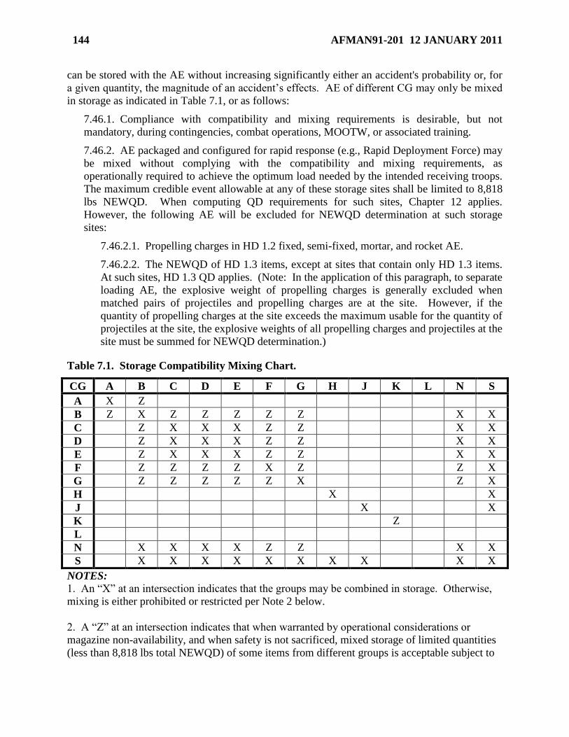
144 AFMAN91-201 12 JANUARY 2011
can be stored with the AE without increasing significantly either an accident's probability or, for
a given quantity, the magnitude of an accident’s effects. AE of different CG may only be mixed
in storage as indicated in Table 7.1, or as follows:
7.46.1. Compliance with compatibility and mixing requirements is desirable, but not
mandatory, during contingencies, combat operations, MOOTW, or associated training.
7.46.2. AE packaged and configured for rapid response (e.g., Rapid Deployment Force) may
be mixed without complying with the compatibility and mixing requirements, as
operationally required to achieve the optimum load needed by the intended receiving troops.
The maximum credible event allowable at any of these storage sites shall be limited to 8,818
lbs NEWQD. When computing QD requirements for such sites, Chapter 12 applies.
However, the following AE will be excluded for NEWQD determination at such storage
sites:
7.46.2.1. Propelling charges in HD 1.2 fixed, semi-fixed, mortar, and rocket AE.
7.46.2.2. The NEWQD of HD 1.3 items, except at sites that contain only HD 1.3 items.
At such sites, HD 1.3 QD applies. (Note: In the application of this paragraph, to separate
loading AE, the explosive weight of propelling charges is generally excluded when
matched pairs of projectiles and propelling charges are at the site. However, if the
quantity of propelling charges at the site exceeds the maximum usable for the quantity of
projectiles at the site, the explosive weights of all propelling charges and projectiles at the
site must be summed for NEWQD determination.)
Table 7.1. Storage Compatibility Mixing Chart.
CG A B C D E F G H J K L N S
A X Z
B Z X Z Z Z Z Z X X
C Z X X X Z Z X X
D Z X X X Z Z X X
E Z X X X Z Z X X
F Z Z Z Z X Z Z X
G Z Z Z Z Z X Z X
H X X
J X X
K Z
L
N X X X X Z Z X X
S X X X X X X X X X X
NOTES:
1. An ―X‖ at an intersection indicates that the groups may be combined in storage. Otherwise,
mixing is either prohibited or restricted per Note 2 below.
2. A ―Z‖ at an intersection indicates that when warranted by operational considerations or
magazine non-availability, and when safety is not sacrificed, mixed storage of limited quantities
(less than 8,818 lbs total NEWQD) of some items from different groups is acceptable subject to
AFMAN91-201 12 JANUARY 2011 145
approval from at least the munitions storage area commander. Approval must be in writing and
must be kept on site. Mixed storage of items within groups where no X or Z exists at that pair’s
intersection, requires a deviation (see paragraph 1.4). Examples of acceptable storage
combinations are:
a. HD 1.1A initiating explosives with HD 1.1B fuzes not containing two or more
effective protective features.
b. HD 1.3C bulk propellants or bagged propelling charges with HD 1.3G pyrotechnic
substances.
3. Equal numbers of separately packaged components of hazard classified complete rounds of
any single type of AE (i.e., missiles, general purpose bombs, etc.) may be stored together. They
may also be stored with assembled rounds made up from these components. When so stored,
compatibility is that of the complete round. That is, group H for WP rounds; group D, E, or F, as
appropriate, for HE rounds. (The ―equal number‖ provision is intended to limit the material
stored to enough packaged components to make up the desired number of complete rounds. It is
not necessary to unpack extra components from normal packaging to make an ―equal numbers‖
condition.)
4. CG K requires not only separate storage from other groups, but also may require separate
storage within the group. AFSC/SEW will determine which items under CG K may be mixed
with other items and which must be kept separate, when such a requirement develops. Request
AFSC/SEW determination through MAJCOM/SEW.
5. AE classed outside Class 1 may be assigned the same CG as Class 1 AE containing similar
hazard features, but where the explosive hazard predominates. Non-Class 1 AE and Class 1 AE
assigned the same CG may be stored together.
6. Ammunition designated ―Practice‖ or ―Target Practice‖ by NSN and nomenclature may be
combined with the fully-loaded ammunition that it simulates (e.g., 2.75-inch target practice
rockets with WP rockets).
7. For purposes of mixing, all AE must be packaged in its standard storage and shipping
container. AE containers will not be opened for issuing items from storage locations. Outer
containers may be opened in storage locations for inventorying and for magazines storing only
HD 1.4 items, unpacking, inspecting, and repackaging the HD 1.4 ammunition. (See paragraph
7.32)
8. When using the ―Z‖ mixing authorized by Note 2 for articles of either CG B or CG F, each
will be segregated in storage from articles of other CG by means that prevent propagation of CG
B or CG F articles to articles of other CG.
9. If dissimilar HD 1.6N AE are mixed together and have not been tested to ensure non-
propagation, the mixed AE are individually considered to be HD 1.2.1 D or HD 1.2.2 D based on

146 AFMAN91-201 12 JANUARY 2011
their NEWQD or overriding fragmentation characteristics for purposes of transportation and
storage. When mixing CG N AE with CG B through CG G or with CG S, see Section 12C to
determine the HD for the mixture.
10. Articles in group L must be segregated in a separate facility or meet the requirements of
paragraph 6.30 - multicubes. Group L articles are not compatible with other articles in group L
unless they are identical items.
AFMAN91-201 12 JANUARY 2011 147
Chapter 8
EXPLOSIVES TRANSPORTATION
Section 8A—Introduction
8.1. Introduction. This chapter gives safety requirements for transporting explosives and for
operating vehicles and materials handling equipment in explosives locations. In-use ammunition
items that must accompany security forces or other defense forces are not governed by
transportation rules. QD criteria does not apply to munitions and explosives in the transportation
mode. Take precautions to ensure minimum exposure of people and property during all phases
of transportation. The time munitions and explosives are in the transportation mode must be
limited to the absolute minimum necessary to complete the task.
Section 8B—Explosives Transportation Standards
8.2. Federal Regulation. Title 49 of the Code of Federal Regulation (CFR) regulates
commercial shipment of hazardous material, including explosives, by rail, motor vehicle, cargo
aircraft and ship within the United States (except maritime explosives). Rules in Title 49 CFR
only apply on military installations when specifically prescribed. For transporting explosives
and munitions on an Air Force installation use the criteria is this Manual. For transporting
military explosives and munitions not on an Air Force installation, but in an Air Force
conveyance, operated by Air Force personnel, the rules in Title 49 CFR must be applied to the
extent they are prescribed in United States Air Force and Department of Defense directives. See
paragraph 8.3 for examples, but not an exhaustive list, of such publications.
8.3. DoD Directives. In addition to this Manual, the following directives apply to military
shipments of hazardous materials within the defense transportation system: AFJI 11-204,
Operational Procedures for Aircraft Carrying Hazardous Material; AFMAN 24-204, Preparing
Hazardous Materials for Military Air Shipment; T.O. 11N-45-51 series, Transportation of
Nuclear Weapons, Materiel, General Shipping, and Limited Life Components (LLC) Data;
Defense Transportation Regulation (DTR) 4500.9R Part 2 and AFJI 24-210, Packaging of
Hazardous Material; AFI 24-203, Preparation and Movement of Air Force Cargo; AFI 24-301,
Transportation Vehicle Operations, MILSTD 129, Military Marking for Shipment and Storage.
8.4. Local Laws Regulating Transportation of Explosives and Dangerous Articles. Each
state and nearly all local and foreign governments have laws or ordinances regulating
transportation of explosives and other dangerous articles within their jurisdiction. Obey local
laws where state, local or host nation governments have jurisdiction. Where there is exclusive
federal jurisdiction, local laws may not apply. Where there is a conflict, contact your MAJCOM
for clarification.
Section 8C—Hazard Classification for Explosives Transportation
8.5. Hazard Classification Requirements for Transportation. Explosives, to be acceptable
for transportation by any mode, must have an assigned hazard classification (HD; storage
compatibility group; DOT class, markings, shipping name and label; and United Nations serial
number), except as noted in paragraph 8.6. Developmental items, test articles, components, and
148 AFMAN91-201 12 JANUARY 2011
certain commercial items that contain explosives, but without a final classification must be
assigned an interim hazard classification. See Chapter 3 for hazard classification procedures.
8.6. Commercial Explosives Hazard Classification Requirements for
Transportation. Commercial explosive items purchased for official use must have a hazard
classification assigned in accordance with T.O. 11A-1-47 before transportation and use, except
as provided in this paragraph. Store, transport, or offer for transportation, commercial explosives
that have not been examined, hazard classified, and approved by DoD in accordance with Title
49 CFR 173.56(b)(2) provided one of the following paragraphs is complied with:
8.6.1. The explosive has been designated, in writing, by the Associate Administrator for
Hazardous Materials Safety (AAHMS), Research and Special Programs Administration,
DOT, as ―Not Regulated.‖
8.6.2. The explosive has been approved for transportation, in writing, by the AAHMS in a
Classification of Explosives, Competent Authority Approval, or in a Confirmation of
Acceptability of a foreign Competent Authority Approval, and the hazard classification of
the explosive is HD 1.4S.
8.7. Compatibility of Explosives During Transportation. Part 177, Subpart C, Title 49 CFR
provides guidance for separating and segregating hazardous materials, including different
explosives, in the various modes of commercial transportation. Explosives transported on a
public highway by Air Force motor vehicles, operated by Air Force personnel, will be separated
and segregated using the rules in Title 49 CFR, except as otherwise provided in this Manual or
other applicable military directives. When an item containing explosives is assigned to other
than hazard class 1 because of the predominant hazard, a compatibility group is still assigned
(see paragraph 3.5.1.2). For these items, compatibility for transportation, and temporary
storage incident to transportation, must be based on rules for the assigned hazard class, not on the
compatibility group. The compatibility group for these items applies only to long term storage.
Cargo-configured items that may be shipped in the same Air Force aircraft are listed in AFMAN
24-204 and T.O. 11N-45-51 series. Procedures for submitting a compatibility waiver for air
transportation of explosives is contained in AFMAN 24-204. The following exceptions to the
above standards are permitted:
8.7.1. Development of new items for transportation by combining previously hazard
classified components into an increased state of assembly to meet a valid military need. Use
normal hazard classification procedures (T.O. 11A-1-47) to obtain the hazard classification
approval for transportation applicable to the new configuration.
8.7.2. Movement of assembled or partially assembled explosive items between servicing
explosives locations and aircraft loading points or other such locations on the same military
installation, when the assembly has not been classed and approved as provided in T.O. 11A-
1-47, but is necessary to meet valid operational requirements. If the operational requirement
is expected to continue or can be anticipated, seek hazard classification approval.
8.7.3. Movement in a military vehicle of minimum quantities of explosive items necessary
for demolition operations, to include proficiency training. Blasting caps, demolition
explosives and unserviceable (but not dangerously unserviceable) munitions may be
transported by the same vehicle, provided MAJCOM approves the mixing of all applicable
AFMAN91-201 12 JANUARY 2011 149
compatibility groups. See paragraph 8.22 for restrictions concerning the carrying of
explosives inside passenger compartments.
8.7.4. Transport dangerously unserviceable munitions in a separate military vehicle. If
transport in a separate military vehicle is not possible, segregate and sandbag from other
explosives being transported. Transport dangerously unserviceable munitions according to
paragraph 8.11 provided the munitions have been determined safe for transportation by
qualified personnel as specified by the MAJCOM.
8.7.5. Movement by a DoD-owned vehicle, operated by DoD personnel, of mixed loads
consisting of components (not otherwise compatible for transportation), in the numbers and
of the types necessary to assemble a number of complete rounds of a single type, when
essential to meet operational requirements, and when separate (unmixed) movement is not
feasible. See DoD 4500.9R, Defense Transportation Regulation, for procedures where such
exceptions to compatibility rules are required.
8.7.6. Movement by a DoD-owned vehicle, operated by DoD personnel, or a mixed load of
small quantities of items (not to exceed 1,000 pounds total NEWQD) from compatibility
groups B through J, N, and S. The NEWQD of HD 1.4S items need not be included.
8.7.7. Movement by Security Forces of mixed loads of ammunition in performance of their
duties.
8.8. Compatibility of Explosives During Temporary Storage. Table 7.1, Title 49 CFR, or
AFMAN 24-204 criteria may be used for temporary mixing of explosives while undergoing
packing and unpacking operations or while in temporary storage awaiting shipment. Do not
store other dangerous articles with these explosives. Shipping, receiving and storage facilities
must comply with QD criteria of this Manual for the HD involved.
Section 8D—Packaging for Explosives Transportation
8.9. Packaging. Packaging of explosives offered for shipment must comply with T.O. 11A-1-
10, Title 49 CFR, Part 173, or AFMAN 24-204 specifications, as appropriate. Follow these
instructions:
8.9.1. Locally made packaging must meet the construction and marking requirements in
Title 49 CFR, or must conform with a military Certification of Equivalency for the item
being packed.
8.9.2. Mark each package to identify contents. The DOT marking consist of the Proper
Shipping Name; United Nations Identification Number; and the EX-number, national stock
number or other product code as specified in the hazard classification. See AFMAN 24-204,
T.O. 11N-45-51, or the Joint Hazard Classification System (JHCS), as appropriate. For
Transportation Protective Service Material, mark in accordance with Defense Transportation
Regulations and MIL-STD-129.
8.9.3. If an item is not listed in above references, contact 505 CBSS/GBBA, Hill AFB UT
84056-5609 for the required data.
8.9.4. Do not open or repair a package in a railcar, motor vehicle, or aircraft unless it is
essential for inflight safety or to safely unload a damaged package. Avoid re-nailing boxes
because of the potential to strike the explosives with the nail.
150 AFMAN91-201 12 JANUARY 2011
8.9.5. If a package is damaged or defective, remove it from the transporting vehicle at the
earliest opportunity for repair.
8.10. Shipment of Explosives Which Have Been Damaged or Failed To Function. If it is
necessary to ship an explosive item that has been damaged, subjected to abnormal force or has
failed to function, ask the responsible AFMC (prime ALC) element for shipping, packing,
marking and safety instructions. For damaged or failed-to-function AE, EOD must determine
that it is safe to ship prior to munitions requesting shipping instructions from ALC.
8.11. Transporting Dangerously Unserviceable Explosive Items for Disposal. Package and
mark dangerously unserviceable items and explosive residue such as partially burned signals as
specified in the item T.O. or EOD technical publications. Consult EOD before transporting
dangerously unserviceable items and explosive residue other than as approved by DOT. DoD
personnel who are properly trained in procedures to be followed and specific hazards of the
material may routinely transport dangerously unserviceable items and explosive residue. Inspect
vehicles using DD Form 626, Motor Vehicle Inspection (Transporting Hazardous Material).
Section 8E—Explosives Movement Routes on Base
8.12. Explosives Movement Routes on Base. Designate the safest possible primary and
alternate explosives movement routes to cover all phases of movement. Identify routes and any
limitations on explosives quantities by hazard class/division on base maps. Avoid built-up areas
and key, mission-oriented facilities and equipment to the maximum extent possible. Movements
of munitions within a munitions storage area, airfield or to and from licensed storage locations
and transportation of explosives in support of the training of working dogs are not restricted to
designated routes.
Section 8F—Incoming and In-transit Explosives Shipments
8.13. Incoming Explosives Shipments. Review guidance in the Transportation Facilities Guide
maintained by Surface Deployment and Distribution Command (SDDC). Contact the base
transportation officer for this guide. The base transportation officer is responsible for
maintaining the base information current in the SDDC database. Clearly state in notification
procedures the NEWQD (and MCE if applicable), by HD, that can be received at unloading
facilities (i.e., railheads, ports, hot cargo pads, etc).
8.14. In-transit Explosives Shipments/Secure Holding. When the SDDC or carrier requests
temporary storage for in-transit shipments of explosives, the responsible commander may
authorize explosives laden carriers to temporarily store their cargo at a Secure Explosives
Holding Area, or Secure Non-explosives Holding Area for HD 1.4S materials (see paragraph
12.64). Furthermore, DoD installations and activities shall provide a secure holding or safe
haven for A&E shipments during emergency conditions (vehicle breakdowns, criminal/terrorist
threat, etc.). Coordinate with the base transportation officer to ensure the Transportation
Facilities Guide correctly reflects the NEWQD (and MCE if applicable), by HD, that can be held
at the Secure Explosives Holding Area. See Defense Transportation Regulation (DTR), Part II,
Chapter 205.Q, AFI 31-101, Integrated Defense, integrated defense plans and AFI 10-2501, Air
Force Emergency Management (EM) Program Planning and Operations, for information. For
guidance on SAFE HAVEN and SAFE parking, refer to AFMAN 32-4004, Emergency Response
Operations, for information.
AFMAN91-201 12 JANUARY 2011 151
8.15. Inspection of Incoming Explosives Shipments. All incoming motor vehicles carrying
hazard class 1 explosives and other hazard class items that carry an explosives compatibility
group, to include HD 1.4 shipments more than 1,001 lbs (in accordance with 49 CFR 172.504),
will be inspected at a designated inspection station by a representative of the Logistics Readiness
Squadron (LRS) commander before further routing on base.
8.15.1. Inspection stations do not require explosives siting if they are limited to the activities
described in paragraph 12.58. If the inspection station is also used as an explosives storage
or suspect vehicle holding area, it must meet QD criteria per Chapter 12. Do not perform
vehicle inspections at the station if it is in use as an explosives storage area or suspect vehicle
holding area. The inspection station may be used as an interchange yard. Vehicles shall be
removed promptly.
8.15.2. Inspections will be done using DD Form 626.
8.15.3. Once a vehicle has passed the initial inspection, a visual inspection of the external
condition of the cargo may be done at any suitable location, including the unloading point.
8.15.4. Any vehicle found or suspected to be in a hazardous condition will be moved to a
suspect vehicle holding area which is isolated from other locations by the proper QD criteria
per paragraph 12.63, unless it is more hazardous to move the vehicle.
8.16. Inspection of Outgoing Explosives Shipments. This paragraph does not apply to the
departure of in-transit explosives shipments. All vehicles to be used for off-base shipments of
explosives will be inspected by shipping activities before and after loading for compliance with
safety regulations.
8.16.1. Complete DD Form 626 according to DTR 4500.9R, Part 2, Chapter 204.
8.16.2. Maintain a record of the vehicle number, the type of explosive cargo, and the number
of each seal applied to the vehicle.
8.16.3. Drivers must be qualified to operate the vehicle and knowledgeable of the explosives
being transported and associated hazards. In addition, Air Force civilian drivers must have a
Commercial Drivers License, with a hazardous materials endorsement, to transport
explosives off a military installation. See AFI 24-301, Vehicle Operations.
8.16.4. DD Form 836, Dangerous Goods Shipping Paper/Declaration And Emergency
Response Information for Hazardous Materials Transported By Government Vehicles, will
be used to instruct drivers on the nature of their cargo, firefighting methods, and other
specific precautions for the particular shipment. Information on the preparation and use of
DD Form 836 is in DTR 4500.9R, Part 2.
8.16.5. Overseas units shall use bilingual instructions on the DD Forms 626 and 836 where
needed.
8.16.6. Where special purpose vehicles are authorized to transport explosive loads,
applicable technical data will be used.
8.16.7. Written procedures will be developed with the base Logistics Readiness Squadron to
ensure procedures and requirements for military vehicles or drivers transporting explosives
(assembled or partially assembled in a delivery mode) across or on public highways from one
part of a base to another are compliant with the Defense Transportation Regulation 4500.9R,
152 AFMAN91-201 12 JANUARY 2011
Volume II, Chapters 204 and 205. Examples may include the transportation of munitions
from a preparation area across the highway to the main base flightline, or on the highway to a
nearby auxiliary field. If this is a daily operation, there shall be an agreement with local
authorities on any local restrictions to be imposed. OCONUS locations must comply with
Host Nation requirements, including any notice requirements contained in host nation law or
applicable international agreements.
8.16.8. Commercial carriers used to move explosives over public highways from one area to
another area of an installation will be externally inspected before entering the second area.
Inspection is not required if the carrier was escorted or under surveillance en route.
8.17. Interchange Yards. This location will be used for the exchange of tractor-trailers
between the common carrier and the base activity involved. Interchange yards do not require
explosives siting if they are limited to the activities described in paragraph 12.59. If the
inspection station is also used as an explosives storage or suspect vehicle holding area, it must
meet QD criteria per Chapter 12. Do not perform vehicle interchange operations at the yard if it
is in use as an explosives storage area or suspect vehicle holding area. The interchange yard may
be used as an inspection station. Vehicles should be removed promptly.
8.18. Holding Yards. If the explosives-loaded vehicles cannot be dispatched to unloading
points promptly, they must be moved to a holding yard. See paragraph 12.60 for holding yard
siting requirements. Holding yards may be used for interchange and inspection activities.
8.19. Classification Yards. Where the volume of vehicle traffic necessitates, establish a
classification yard primarily for receiving, classifying, switching, and dispatching explosives-
laden vehicles. Classification yards do not require explosives siting if they are limited to the
activities described in paragraph 12.61. If the classification yard is also used as an explosives
storage or suspect vehicle holding area, it must meet QD criteria per Chapter 12. The
classification yard may be used as an interchange yard. Vehicles should be removed promptly.
8.20. AE Transportation Mode Change Locations. Transportation mode change locations
require explosives siting as per paragraph 12.62.
Section 8G—Transportation and Movement of Explosives by Motor Vehicle and Material
Handling Equipment
8.21. General. This section covers the transport and handling of explosives by DoD motor
vehicle and material handling equipment. The requirements of this section also apply to DoD
rental vehicles when used to transport DoD explosives on military installations. Do not transport
DoD explosives in POVs under any circumstance.
8.21.1. Chock explosive loaded vehicles and material handling equipment (MHE) when
parked and the driver is not behind the wheel. Chocking MHE is not required if the
explosives load is lowered and completely resting on the ground.
8.21.2. Other forms of explosives loaded MHE (trailers, universal ammunition loading
systems (UALS), etc.) will be chocked when parked and/or left unattended.
8.22. Transporting Explosives in Passenger Compartments. Do not transport explosives in a
passenger compartment of a vehicle, except as authorized below.
AFMAN91-201 12 JANUARY 2011 153
8.22.1. Minimum essential personnel and limited quantities of HD 1.4, 1.3, and 1.2.2
explosives, as approved by the local OI, may be transported together in cargo portion of
vehicles (including Metro type vans used on flightlines) or in vehicles used as runway
supervisory units.
8.22.2. Egress system assembled components may be transported in the cargo compartment
of Metro-type vehicles.
8.22.3. For emergency responses in vehicles without separate cargo compartments (e.g.,
robot vans, Metro-type vehicles, HMMWV, EOD Base Support Emergency Response Van
(BSERV), Mine Resistant Ambush Protected (MRAP) family of vehicles), EOD units are
authorized to transport minimum essential quantities of all HDs inside the vehicle. Separate
incompatible explosives to the maximum extent possible.
8.22.4. Basic load munitions issued to emergency response personnel in the performance of
their duties are exempt from these requirements. Basic loads can include HD 1.1 40mm
grenades, LAW rockets, etc. However, transportation of re-supply stocks must comply with
all the requirements of this paragraph.
8.22.5. When units responsible for demolition operations are issued vehicles without
separate cargo compartments, such vehicles may be used to transport minimum quantities of
explosives necessary to support demolition. Trailers will be used to the maximum extent
possible.
8.23. Transporting Electro-Explosive Devices. When transporting items containing EEDs,
fully consider EMR hazards discussed in Chapter 9. Vehicles with plastic bed liners may be
used to transport EEDs that are in their original sealed outer package, box, or container. Metal
ammo-type containers may be used to transport EEDs in vehicles with plastic bed liners if the
containers provide the protection required by paragraph 7.9.2 and are bonded to the metal body
of the vehicle.
8.24. Transporting Aircraft Seats and Survival Kits. Aircraft seats and survival kits with
explosive devices installed must contain required safety pins and devices and be secured to
prevent movement during transit.
8.25. Packaging. Transport explosives in their approved storage and shipping packaging. If
less than a single shipping package must be transported, pack the explosives separately from
other items in enclosed, clearly marked metal or wooden containers.
8.26. Placarding.
8.26.1. Use DOT placards as outlined in Subpart F of Title 49 CFR, Part 172. When
transporting munitions off the installation in a foreign country comply with host nation
requirements.
8.26.2. Commanders may omit placards on base where necessary to avoid attention of
hostile forces. Instruct all personnel in proper emergency actions.
8.26.3. Where tow vehicle and trailer combinations are used on base, placard the lead
vehicle on the front and the last vehicle on the rear. Placard loaded vehicles in between on
each side. Placards may be omitted for transporting HD 1.4 material on base.
154 AFMAN91-201 12 JANUARY 2011
8.26.4. Placard materials handling equipment only when used in the same manner as a
transport vehicle or trailer.
8.26.5. Compatibility group letters may be omitted from the placard if the vehicle remains
on the installation.
8.26.6. Placards are not required when transporting nuclear weapons or on any explosives
loaded vehicle in a nuclear weapons storage area.
8.26.7. Vehicles transporting Military Working Dog Explosives Search Training kits must
be properly placarded.
8.27. Motor Vehicle Inspection. Prior to use, inspect motor vehicles used to transport
explosives to determine that:
8.27.1. Fire extinguishers are available, filled, and in good working order (see paragraph
10.23).
8.27.2. Electric wiring is in good condition and properly attached.
8.27.3. Chassis, motor, pan, and underside of body is reasonably free of oil, grease, and fuel.
8.27.4. Fuel tank and feed lines are secure and not leaking.
8.27.5. Brakes, steering, lights, horn and windshield wipers are functioning properly.
8.27.6. Tires are properly inflated and serviceable IAW T.O. 36-1-191.
8.28. Load Protection and Stability.
8.28.1. Cover exposed ferrous metal in the cargo compartment before transporting
explosives that are not packaged in DOT specified containers or equivalent.
8.28.2. Use only static resistant and noncombustible or flameproof tops or coverings.
8.28.3. Fasten safety chains between towing vehicles and trailers carrying explosives when
lunette and pintle fastenings are used. Safety chains are not required when using specifically
designed breakaway control safety features prescribed by the pertinent T.O.
8.28.4. Ensure lifting devices on vehicles or handling equipment have a serviceable
mechanism designed to prevent sudden dropping of the load in the event of power failure.
8.28.5. Loads on the tines of a forklift must not extend more than one-third of the height of
the top tier of containers above the backrest.
8.28.6. Ensure forklifts use skids or pallets to move containers of explosives, except when
containers are designed with fully enclosed stirrups (360 degrees) for forklift tines.
8.28.7. Munitions may be carried on forklift tines when the weapon body is long enough to
be firmly supported on both tines and strong enough to prevent damage.
8.28.8. Ensure munitions loads (AE and inert AE components) on all types of vehicles and
handling equipment are stable and secure before movement. Load stability is required for all
movements, to include rewarehousing or other activities conducted between one or more
storage magazines, storage pads or other operating location. For on base movements,
munitions loads (AE and inert AE components) must be restrained, blocked, braced, tied
down or otherwise secured to the vehicle to prevent movement and must not damage

AFMAN91-201 12 JANUARY 2011 155
explosives or containers. "Secure" means the load is protected by an effective restraining
system. Restraining devices may include chains and binders, cargo nets and tie-down straps,
sideboards and tailgates, etc.
8.28.9. Consider vehicle and handling equipment type, type of load, and the prevailing
weather and road conditions when determining if safe transport is feasible. This guidance
pertains to munitions storage area as well as applicable flightline operations.
8.29. Loading and Unloading.
8.29.1. Chock explosives loaded vehicles and MHE (trailers, UALS, etc.) during loading or
unloading operations.
8.29.2. To the maximum extent possible, position munitions cargo vehicles to permit loading
and unloading from each side of the cargo bed. Munitions will be accessed from the side
closest to the load unless access can only be obtained from one side.
8.29.3. Except as required in the event of an electrical storm (see Section 7H), do not leave
explosives-laden vehicles unattended unless they are parked in a properly designated area,
such as the weapons storage area, holding yard or flightline munitions holding area.
8.29.4. Do not load or unload explosives from a motor vehicle while the engine is running,
except under the following conditions:
8.29.4.1. Where the engine is required to provide power to vehicle mechanical handling
equipment used in loading and unloading the vehicle.
8.29.4.2. Where necessary for emergency operations or timing for exercises simulating
execution of emergency plans. In this case, small loads or packages of explosives
delivered to aircraft, requiring only momentary unloading time, may be removed from a
vehicle while the motor is running.
8.29.4.3. Engines of diesel-powered vehicles may continue to run during loading or
unloading of explosives except when exposed explosives or hazardous locations are
involved.
8.29.4.4. Adequate ventilation is provided to prevent unnecessary build-up of exhaust
gases.
8.29.5. Do not leave vehicles at aircraft or storage locations longer than needed to complete
explosives loading or unloading. If a delay occurs, move the vehicle from location.
8.29.6. Refuel trucks before loading explosives.
8.30. Vehicle Refueling.
8.30.1. Refuel non-explosives loaded vehicles and equipment at least 100 feet from
structures or sites containing explosives.
8.30.2. When refueling explosives-loaded vehicles, maintain a bonded path between the tank
being filled and the tank being emptied. Ground the entire system. Refer to Section 7D for
further guidance on static grounding.
8.30.2.1. When refueling is completed, remove refueling vehicle from the storage area.
8.30.2.2. Use the smallest available size of refueling unit.
156 AFMAN91-201 12 JANUARY 2011
8.30.2.3. One person must be present during the entire operation.
8.30.2.4. During refueling, stop motors of vehicle being refueled and refueling truck
(unless refueling truck motor drives the pump).
8.30.2.5. In event of a fuel spill, immediately notify the base fire department. Do not
start motors of refueling truck or unit being refueled until area is rendered safe.
8.31. Battery-Powered Materials Handling Equipment. Battery-powered equipment is
preferred for handling explosives and should be used when possible.
8.31.1. Electrical cables will be mounted to prevent catching on stationary objects or damage
by cutting or abrasion. Cables will be protected to prevent short-circuiting as far as is
practicable.
8.31.2. Batteries will be securely fastened. Battery boxes will give ample ventilation, with
ventilation openings that prevent access to the cell terminals from the outside.
8.31.3. Equip with a dead-man switch and a main service switch that can be operated from
the driving position.
8.32. Gasoline or Diesel-Powered Materials Handling Equipment.
8.32.1. Equip with a standard muffler and air cleaner.
8.32.2. Ensure gas caps are in place.
8.32.3. If necessary, install a deflector plate to prevent overflow from the fuel tank from
reaching motor or exhaust pipe.
8.32.4. On gravity feed fuel systems or on pump systems that can be siphoned, install an
emergency shutoff valve at fuel tank or in the feed line.
8.32.5. Protect fuel lines from rupture due to vibration.
8.32.6. Securely fasten electrical connections to prevent accidental disconnection that might
result in sparks or fire.
8.32.7. Do not use equipment in areas classified as hazardous locations
8.33. Liquefied Petroleum and Compressed Natural Gas Fueled Vehicles. Motor vehicles or
other equipment used to transport explosives which use Liquefied Petroleum (LP) or
Compressed Natural Gas (CNG) for propulsion must have a fuel system which complies with the
current edition of the National Fire Protection Agency, Standard 58, Section 8.2.6, Engine Fuel
Systems.
8.34. Exposed Explosives Precautions. Do not use battery, gasoline or diesel-powered
vehicles and materials handling equipment inside any structure or building containing exposed
explosives. Vehicles or equipment may be used within the vicinity of structures containing
exposed explosives providing:
8.34.1. Gasoline or diesel-powered units have exhaust system spark arrestors and, where
applicable, carburetor flame arrestors (standard air cleaners).
8.34.2. Spark arrestors meet military specifications for the particular equipment and are
installed so they will not become clogged in normal operation (AFOSH Standard 91-66,
Occupational Safety General Industrial Operations, and T.O. 38-1-23, Inspection and
AFMAN91-201 12 JANUARY 2011 157
Installation of Exhaust Spark Arrestors and Exhaust Purifiers (Catalytic Mufflers) on Non-
Aircraft Engines).
8.34.3. Vehicle operators inspect spark arrestors before each daily use and clean them if
there is an excess of carbon particles.
8.35. Storage of Powered Materials Handling Equipment. Battery, gasoline, LP, CNG, or
diesel-powered equipment may be stored in a magazine, storehouse or other suitable location that
contains only non-explosives materials. Keep equipment at least 10 feet from combustible
material. Keep aisles clear at all times and space to minimize spread of fire from one unit to
another. Equipment essential to day-to-day operations may be parked in fire-resistive buildings
containing explosives. The following minimum requirements must be met:
8.35.1. Use properly rated fire walls and closed doors to completely separate equipment
from bays, rooms or cubicles containing explosives.
8.35.2. Ensure designed fire-resistant ratings for the enclosures containing explosives are not
degraded.
8.35.3. Battery charging must comply with AFOSH Standard 91-66.
8.35.4. Weapons safety and fire protection personnel must review the local situation for any
additional measures necessary to enhance safety.
8.36. Operating Powered Materials Handling Equipment Inside Structures. Concentration
of carbon monoxide in the operating area must not exceed the current occupational exposure
limit. Consult the local bioenvironmental engineer for a determination of exposure levels,
applicable exposure standards, and recommended controls.
8.37. Maintenance of Vehicles Carrying Explosives.
8.37.1. Only operator inspection and maintenance normally related to the operation of a
vehicle will be done on explosives-laden vehicles. Such maintenance includes servicing with
fuel, oil, air, lubrication and water, changing tires, fuses, hoses and drive belts, etc.
8.37.2. No maintenance will be done on an explosives-loaded vehicle or trailer that would
increase the probability of fire or would require the use of heat-producing equipment.
8.37.3. No restrictions are imposed on tractor maintenance when the tractor is separated by
at least 100 feet from an explosives-loaded trailer.
8.37.4. When tires are being changed, the vehicle or trailer must not be elevated so as to shift
the load or place an excessive strain on the tiedowns.
8.37.5. Vehicles carrying nuclear weapons are subject to the maintenance restrictions in T.O.
11N-45-51 series.
Section 8H—Transportation of Explosives by Rail
8.38. General.
8.38.1. 49 CFR, Part 174 and DOT safety regulations for safety devices, safeguards, design
of equipment, etc., are mandatory for railway equipment transporting materials outside an
installation. These regulations should also be followed within an installation.
158 AFMAN91-201 12 JANUARY 2011
8.38.2. Special attention should be given to rail clearances to buildings, loading docks,
overhead lines, etc.
8.38.3. Locomotives. Portable fire extinguishers will be carried on all locomotives and
other self-propelled rail vehicles as directed in paragraph 10.23.2.
8.38.4. Track Layout. Railroad lines serving explosives areas should be looped to give at
least two ways of exit.
8.38.5. Control vegetation along the railroad right-of-way on the base as directed in
paragraph 10.16.
8.39. Movement of Railcars Containing Explosives.
8.39.1. By Engine. Secure load and cut in air brakes before movement. Cars should not be
uncoupled while in motion or pulled apart by locomotive power.
8.39.2. By Car Mover. Station an individual at the hand brake during any manual
movement of a car.
8.40. Spotting Railcars.
8.40.1. Set hand brakes and properly chock wheels when spotting single cars. When more
than one car is spotted and the engine detached, set hand brakes on the downgrade end of the
cut of cars. Do not rely on the automatic air brakes to hold spotted cars.
8.40.1.1. Locomotives will not stop in front of buildings and loading docks containing
hazardous materials longer than needed to spot cars for loading or unloading.
8.40.2. Cars at a magazine or building should be located so that personnel may evacuate the
building or car rapidly if necessary.
8.41. Switching Railcars.
8.41.1. Special care will be taken to avoid rough handling of cars.
8.41.2. Cars must not be cut off while in motion. Cars will be coupled carefully to avoid
unnecessary shocks. Other cars will not be cut off and allowed to strike a car containing
explosives.
8.41.3. Place cars in yards or on sidings so they can be quickly removed from the danger of
fire and handled as little as possible. They will not be placed under bridges or alongside
passenger sheds or stations. Engines on a parallel track should not be allowed to stand
opposite or near them.
8.41.4. Dropping, humping, kicking, or use of the flying switch is prohibited.
8.42. Marking Railcars with Blue Flags or Signals. Place blue flags or signals at both ends of
a car when personnel are working in, on, or under the cars, except as noted below. Do not move
or couple cars marked in this manner. The supervisor or foreman in charge of the personnel
loading or unloading the cars is responsible for placing and removing the blue flag or signal.
Inform train crews in the use of blue flags or signals.
8.42.1. Flags are not required when flat cars are involved and the presence of a working
party is clearly evident.
AFMAN91-201 12 JANUARY 2011 159
8.42.2. Flags or signals may be omitted from the end of a car located against or toward a
dead end spur. This also applies to a loading ramp where no other rolling stock can approach
from that direction.
8.43. Loading Railcars.
8.43.1. Inspect car thoroughly, inside and out, to determine its suitability to carry the type of
explosives involved.
8.43.2. Broom clean the interior of the car before loading explosives.
8.43.3. Remove or cover protruding nails and bolt heads to prevent damage to packages.
8.43.4. Provide substantial gangways.
8.43.5. Remove any obstructions that may prevent free entry to the car.
8.43.6. Clear immediate area of leaves, dry grass, and other flammable materials.
8.43.7. Close the car and magazine doors during loading operations when engines or
speeders are passing.
8.43.8. Do not leave cars partly loaded unless it is impossible to finish loading at one time.
In this case, lock car doors.
8.43.9. If it becomes necessary to move a partially loaded car, brace the load.
8.43.10. During and after loading, properly brace and stay the shipment per paragraph 8.44.
8.43.11. After loading, seal the car per paragraph 8.49.
8.44. Loading and Bracing. When loading freight cars, consult Bureau of Explosives
Pamphlets 6 and 6A and 49 CFR, Part 174 for guidance unless specific instructions or car
loading drawings are available for the items involved. These pamphlets govern the method of
loading, staying, and bracing of carload and less-than-carload shipments of explosives. Refer to
Bureau of Explosives Pamphlet 6C for guidance in securing truck bodies or trailers on flat cars.
Also see this pamphlet for loading, blocking, and bracing of the cargo within, or on, such
vehicles or containers. The carrier or cargo must not shift under an impact of 8 miles per hour
from either end. Obtain Bureau of Explosives pamphlets by writing: Bureau of Explosives, 50F
St. NW, Washington DC 20336.
8.45. Placarding of Railcars.
8.45.1. Placard railcars transporting explosives according to paragraph 8.26.1.
8.45.2. Display placards when the first container of explosives is loaded in the railcar.
Remove placards when the last container of explosives is removed from the railcar.
8.45.3. Four placards are required for each railcar. It is the responsibility of the shipper to
furnish the needed placards.
8.45.4. Where necessary, to avoid attention of hostile forces, commanders may omit placards
when arrangements are made with the host nation or governmental agency involved. Instruct
all involved (including essential train crews) in proper emergency actions.
8.46. Railcar Requirements.
160 AFMAN91-201 12 JANUARY 2011
8.46.1. Cars used for the shipment of material requiring placarding under Title 49 CFR, Part
172, must meet standards for the class of material being shipped as specified in Title 49 CFR,
Part 172.
8.46.2. Inspect cars for HD 1.1 explosives before and after loading.
8.46.3. Accomplish, distribute, and affix car certificates according to Title 49 CFR, Part
174.104.f.
8.47. Leaking Packages in Railcars.
8.47.1. Continually be alert to detect leaking packages or leaking tank cars.
8.47.2. Remove and repair leaking packages from cars. In the case of tank cars, transfer the
contents.
8.47.3. Switch leaking tank cars containing compressed gases to a location distant from
habitation and highways. The on-scene commander should determine the appropriate
distance. Take action to transfer contents.
8.47.4. Protect cars containing leaking packages or leaking tank cars to prevent ignition of
liquid or vapors.
8.47.5. Hold to a minimum the movement of a leaking car until the unsafe condition is
corrected.
8.47.6. If artificial light is necessary, use only approved explosion proof electric lights.
8.48. Tools for Loading and Unloading Railcars. Steel tools, used with reasonable care, may
be used inside cars if explosives are not exposed. When explosives are exposed, special care will
be taken to prevent sparks.
8.49. Sealing Railcars.
8.49.1. Seal cars containing explosives with railway-type car seals stamped with an identifying
number. The shipper will keep a record of car numbers and seals (see DoD 4500.9R, Defense
Transportation Regulation, for additional car seal regulations).
8.49.2. When a car seal is changed on a car of explosives, record the following
information:
8.49.2.1. Railroad.
8.49.2.2. Place.
8.49.2.3. Date.
8.49.2.4. Number or description of seal broken.
8.49.2.5. Number or description of seal used to reseal car.
8.49.2.6. Reason for opening car.
8.49.2.7. Condition of load.
8.49.2.8. Name and occupation of persons opening car. Document this record on
waybills or other forms or memorandum that accompanies car to destination.
8.50. Processing Incoming Loaded Railcars.
AFMAN91-201 12 JANUARY 2011 161
8.50.1. A competent representative will inspect railcars containing explosives at a designated
inspection station. Inspection stations do not require explosives siting if they are limited to
the activities described in paragraph 12.58. If the inspection station is also used as an
explosives storage or suspect vehicle holding area, it must meet QD criteria per Chapter 12.
The inspection station may be used as an interchange yard. Railcars should be removed
promptly.
8.50.2. Inspect the outside and underside of each car to detect damage (such as defective
brakes, couplings, wheel flanges, or hot boxes) or unauthorized and suspicious articles.
8.50.3. If pits are not available, conduct inspections from ground level. Provide pits if
sabotage is possible.
8.50.4. If rail traffic is heavy enough or in an emergency, a pit will help in inspecting and
moving cars rapidly.
8.50.5. Isolate cars of explosives for prompt corrective actions when foreign and suspicious
articles have been attached outside or underneath the car. Also isolate when there is a defect
that could affect installation safety or car contents.
8.50.5.1. Move car, unless the problem prohibits, over the safest route to a location
separated from other areas by proper inhabited building distances.
8.50.5.2. Correct the unsatisfactory conditions before the car and cargo are released from
the designated suspect car site, unless a determination is made that they are safe to move.
8.50.6. Check individual car numbers and seal numbers against bills of lading. If the seal
numbers on a car do not correspond to the numbers shown on the bill of lading, or a seal is
not in place, treat as a suspect car. Remove it to the suspect car siting for additional
inspection.
8.50.7. Visual inspection of the external condition of the cargo in cars that pass the initial
inspection may be done at any suitable place, including the unloading point. Such cars may
be considered reasonably safe. However, exercise care in breaking seals and opening doors
because of the potential for shifted loads or leaking containers.
8.50.8. If warranted by the inspection results, promptly remove cars from the inspection
station.
8.50.9. Externally inspect commercial carriers used to move explosives through a public
access route, from one area to another area of the installation, before entering the second
area. This is not needed if it is escorted or under surveillance enroute.
8.51. Rail Interchange Yards. This location will be used for the exchange of railcars between
the common carrier and the base activity involved. Interchange yards do not require explosives
siting if they are limited to the activities described in paragraph 12.59. If the inspection station is
also used as an explosives storage or suspect vehicle holding area, it must meet QD criteria per
Chapter 12. The interchange yard may be used as an inspection station. Railcars should be
removed promptly.
8.52. Rail Holding Yards. If explosives-loaded railcars cannot be dispatched to unloading
points promptly, they must be moved to a holding yard. See paragraph 12.60 for holding yard
siting requirements. Holding yards may be used for interchange and inspection activities.
162 AFMAN91-201 12 JANUARY 2011
8.53. Rail Classification Yards. Where the volume of rail traffic necessitates, establish a
classification yard primarily for receiving, classifying, switching, and dispatching explosives-
laden railcars. Classification yards do not require explosives siting if they are limited to the
activities described in paragraph 12.61. If the classification yard is also used as an explosives
storage or suspect vehicle holding area, it must meet QD criteria per Chapter 12. The
classification yard may be used as an interchange yard. Railcars should be removed promptly.
8.54. Trailers on Flat Cars or Piggyback Explosives Loading and Unloading. The following
instructions govern use of explosives Trailers on Flat Cars (TOFC) railheads:
8.54.1. Control loading or unloading operations to reduce exposures to a minimum.
8.54.2. Quickly remove trailers from the railroad car and send at once to their destination or
schedule for prompt loading on arrival at the site. If there is an unforeseen delay in loading
or unloading, an explosives-loaded trailer may be kept at the site for a period not exceeding
one working day.
8.54.3. Don't open piggyback shipping trailers and containers at the site except for
emergency or suspected emergency situations, except as for Shipping and Storage
Containers, Ballistic Missile (SSCBM). SSCBM received by TOFC may be opened at the
site for inspection and road transport preparation as required by pertinent T.O.s.
8.54.4. Ensure adequate tie-down of trailers to railcars and blocking and bracing of
explosives in the trailer. Cargo stability in transit is essential.
8.54.5. Apply safety rules in this chapter on explosives-laden motor vehicles and their
operation.
8.54.6. The provisions of Bureau of Explosives Pamphlet 6C apply to explosives piggyback
operations (the pamphlet lists railcars and hitches approved for TOFC service).
8.54.7. Except for those just discussed, do not conduct operations on explosive items or
explosives-laden containers, trailers, cars, etc., unless applicable QD criteria are met.
Section 8I—Transportation of Explosives by Air and Water
8.55. Transportation of Explosives by Air. Air transportation of explosives by commercial
aircraft is regulated by the DOT regulations that are incorporated into Title 49 CFR. Instructions
about explosives-laden military aircraft (and certain DoD contract airlift operations) are in AFJI
11-204, Operational Procedures for Aircraft Carrying Hazardous Material, AFMAN 24-204,
Preparing Hazardous Materials for Military Air Shipments, applicable aircraft T.O.s, and other
parts of this Manual. Transportation of impulse cartridges (HD 1.4 only) in aircraft travel pods
or bomber aircraft equipment bays is permitted if these cartridges are packed correctly in the
original DOT shipping containers. This procedure will be governed by locally approved
operating instructions IAW paragraph 7.2. More hazardous explosives (such as aircraft flares)
are not authorized by this Manual for this type of carriage. See guidance in paragraph 8.2 for
using NEWQD during transportation.
8.56. Transportation of Explosives by Water. Transportation of explosives and other
hazardous materials by water in vessels engaged in commercial service is regulated by the
United States Coast Guard. Shipments overseas must be made according to the regulations of
the carrier, the United States Coast Guard or the Department of the Army.
AFMAN91-201 12 JANUARY 2011 163
Chapter 9
PROTECTION OF ELECTRO-EXPLOSIVE DEVICES FROM HAZARDS OF
ELECTROMAGNETIC RADIATION TO ORDNANCE (HERO)
Section 9A—Hazards of Electromagnetic Radiation to Electro-Explosive Devices
9.1. Chapter Overview. This chapter is consistent with Air Force policy under DoDD
3222.3_AFPD 33-5, DoD Electromagnetic Environmental Effects (E3) Program, paragraph
4.1.3, which states ―Hazards of Electromagnetic Radiation to Ordnance HERO…shall be
mitigated prior to the conduct of all military exercises, operations, and activities.‖ It also
addresses the requirement in DoD 6055.09-M, Volume 2, HAZARDS OF ELECTROMAGNETIC
RADIATION TO ORDNANCE (HERO), that ―Military Munitions…shall be…protected such that
electromagnetic radiation (EMR) does not cause their inadvertent initiation, degradation or
disablement.‖ In addition to electro-explosive devices (EEDs) installed in ordnance and
ordnance components, the protective methods described in this chapter will be applicable to
individual EEDs, as well as all EEDs installed in aircraft. Throughout this chapter the term EED
can be used interchangeably with munitions or ordnance.
9.2. Conducted Electromagnetic Energy. Conducted electromagnetic energy is imposed on
circuits from other subsystems or sources by various methods. Examples are inductive or
capacitive coupling from other cabling, sneak ground circuits, defective components or wiring,
or errors in design. Protection of EEDs from conducted electromagnetic energy should be
designed into a weapons system as part of the system safety design process.
Section 9B—Definitions and Conversion Formulas
9.3. Antenna Gain (Gt). Antenna gain is a measure of the power channeled by a directional
antenna. It is usually provided in decibels (dB). Sometimes it is provided as a unitless number,
Gt. Use the following formula to convert between GdB and Gt:
10GdB1
tdB10
10
GlogG
9.4. EED Susceptibility Terms. Two types of EMR susceptibility can be defined for each
EED.
9.4.1. Maximum No Fire Current (MNFC). The MNFC is a value statistically determined
by experimental testing that quantifies the largest current amplitude that can be induced in
the EED leads without initiating a reaction. The units for MNFC are usually milliamperes
(mA).
9.4.2. Maximum No Fire Power (MNFP). The MNFP is a value statistically determined
by experimental testing that quantifies the largest power that can be absorbed by the EED
without initiating a reaction. The units for MNFP are usually milliwatts (mW).
9.4.3. Bridgewire Resistance. The two susceptibility values (above) are related by a third
value with units of Ohms (
resistance value. The MNFP is equal to the resistance multiplied by the MNFC squared. If
164 AFMAN91-201 12 JANUARY 2011
to calculate the other value.
9.5. Effective Isotropic Radiated Power (EIRP). The EIRP is equal to the actual transmitted
power level (Pt) multiplied by the antenna’s gain (Gt). The EIRP is defined as the amount of
power an emitter would have to transmit equally in all directions (isotropically; if Gt = 1) to
equal the power levels at the maximum point of the antenna pattern.
9.6. Electromagnetic Environment (EME). The EME is defined by the frequencies and power
levels the EED will be exposed to at a given location due to all known sources of EMR.
9.7. Far Field/Far Field Distance (Rff). The Far Field of an antenna is any location farther
from the antenna than the Far Field Distance. The Far Field Distance is the point where the
equations for the radiated electromagnetic field can be replaced with simpler equations and the
difference has dropped below a threshold margin of error accepted by engineers. The simpler
Far Field EMR equations describe a more consistent power density environment and the
propagation and coupling of the EMR to a receiving antenna is easier to apply to the EED
scenario.
9.7.1. Use the greater resultant from the following formulas to determine where the far field
begins:
Rff = L2(f/c)
Rff = 3(c/f)
Rff = distance, in meters (or feet), from transmitting antenna where the far field begins
L = largest dimension of the antenna, meters (or feet)
f = frequency (Hz)
c = speed of light, 3x10⁸ m/s (or 984x10
6 ft/s)
9.7.2. When the size or dimensions of the emitter aperture are not known, the following
equation should be used to determine the worst-case aperture size:
8.2
G)
fc(L t
9.8. Frequency (f). Frequency is measured in hertz (Hz) or cycles per second. Use the
following formulas to convert between kHz (1000 Hz), MHz (1,000,000 Hz), and GHz
(1,000,000,000 Hz):
1 kHz = 0.001 MHz
1 GHz = 1000 MHz
9.9. HERO Certification. DoD 6055.09-M, defines HERO certification as ―exposure, without
adverse effects, of the munitions to the electromagnetic environment (EME) relevant to all life
cycle configurations, including packaging, handling, storage, transportation, checkout, loading
and unloading, and launch.‖ This definition is dependent on the EME and the configurations of
the munitions during operations.
AFMAN91-201 12 JANUARY 2011 165
9.10. HERO Classifications. Three possible HERO Classifications are available. The choice of
classification is based upon the EED’s susceptibilities to EMR, the configuration of the EED,
and the EME the EED will experience during the planned operational event. The EME for EIDs
is given in MIL-STD-464C, paragraph 5.9.3. and tables 9 and 10. HERO Classification is a
temporary label used only to determine the proper procedures to follow to achieve the level of
protection the EED requires to safely complete the planned operations.
9.10.1. HERO SAFE. If the EED is incapable of being initiated by EMR in its expected
EME, either by design or by shielding, the EED shall be classified as HERO SAFE and no
further protection is necessary.
9.10.2. HERO SUSCEPTIBLE. If the EED could potentially be initiated by EMR in its
expected EME, the EED shall be classified as HERO SUSCEPTIBLE and protective efforts
are required.
9.10.3. HERO UNSAFE. If susceptibility data for the EED is known to be less than the
values used to establish the ―worst-case‖ protective requirements (54mW MNFP and/or less
than 85mA MNFC), the EED shall be classified as HERO UNSAFE and additional
protective efforts are required. Examples of HERO UNSAFE EEDs include items not
classified as SAFE or SUSCEPTIBLE, those with internal wiring exposed, items with
exposed wire leads when handled in untested conditions, items being assembled or
disassembled, and items with damage causing exposure of internal wiring.
9.11. Modern Mobile Emitters (MME). The term MME is used to describe all RF emitters
that have the capability of moving with regard to the location of the EED, as well as any other
low power emitters that are part of modern communication and data systems that include mobile
emitters. This potentially invalidates the ―far-field‖ approximations used to simplify the radiation
theory and coupling models used when EMR safety requirements were analyzed with regard to
these emitters. This category includes cellular phones, Personal Digital Assistants (PDAs),
barcode readers and RFID devices, wireless computers and network access points, and any other
transmitter that can potentially be brought close to EEDs, even to distances less than the emitter
antenna’s far-field distance
9.12. Near Field. The Near Field of an antenna is any location closer to the antenna than the
Far Field Distance. In the Near Field, the equations for the radiated electromagnetic field must
be used without simplification and calculating the coupling of EMR to a receiving antenna
becomes very complicated and difficult. For example, in the Near Field of an aperture antenna,
there is a reduction of antenna gain that can possibly provide some safe separation distance
(SSD) relief, however, in the Near Field of a dipole antenna, there is an increase in antenna gain
that increases the SSD. For a more detailed explanation of near-field calculations, see TO 31Z-
10-4, Air Force EMR Hazard Program (Chapter 6, Section II, Calculating Power Density and
Hazard Distance).
9.13. Safe Separation Distance (SSD). The SSD is the calculated distance from an emitter
beyond which the radiated power density from that emitter has decreased to a level which is too
low to couple enough energy into an EED to initiate detonation. Measurement of the SSD may
take into account the vertical difference in height between the emitter and the EED or weapon
meant to be protected.
166 AFMAN91-201 12 JANUARY 2011
9.14. Traditional Fixed-Location Emitters (TFE). The term TFE is used to describe all RF
emitters that have been traditionally tracked by the Installation Spectrum Manager. These
emitters are in a fixed location, usually mounted on a tower, mast or rooftop, and usually radiate
a fairly high EIRP, hundreds if not thousands of Watts. These features often allow the
application of ―far-field‖ approximations to simplify the radiation theory and the application of
coupling models when EMR safety requirements are being analyzed with regard to these
emitters.
9.15. Transmitted Power (Pt). Transmitted power, Pt, is expressed in Watts (W). For
continuous systems, the peak radiated power should be used. For pulsed systems, calculate Pt as
follows:
Pt = Ppk x PW x PRF
Ppk = Peak radiated power, in Watts
PW = Pulse Width, the duration of the pulse, in seconds
PRF = Pulse Repetition Frequency, the number of pulses transmitted each second,
in Hz (1/sec)
Section 9C—HERO Protection Overview
9.16. Radiated Electromagnetic Energy. EEDs are typically designed to be initiated by low
levels of electrical energy injected directly into the lead wires of the device. As such, they are
susceptible to unintentional ignition by many forms of direct or induced electrical energy, such
as from lightning discharges, static electricity, or the coupling of radio frequency (RF) energy
into the lead wires. This RF energy can be transmitted by ground based or airborne emitters
(antennas), both from fixed or mobile locations, and at a range of power levels and frequencies
that can vary over several orders of magnitude. Once transmitted, EMR propagates at the speed
of light and all electrically conducting objects in its path can potentially act as receiving antennas
for this energy.
9.17. EMR Protection Information. The only way to guarantee protection of an EED from the
hazards of EMR is to ensure that the EED is never located where the RF power density is
sufficiently high to couple enough electrical energy into the device to initiate detonation. This
seemingly simple prescription involves knowing several critical pieces of information: the RF
power density present, the capability of the energy to couple into the EED, and the threshold
energy required to put the EED at risk for initiation. This information is in turn dependent on the
type of EED under consideration, the specific location of the EED, the configuration of the EED,
and the operational tasks being performed. The complexity and layered nature of this information
quickly complicates the protection process.
9.18. EMR Information Categories. All the information required to guarantee the protection
of EEDs from EMR hazards can be organized into five categories of knowledge, depicted in
Figure 9.1.
9.18.1. Category A. The location, frequency, transmitting power levels and transmitting
pattern (gain) of all antennas that could potentially affect the EED.
9.18.2. Category B. The fundamentals of radiation theory.
9.18.3. Category C. The coupling models used to describe the interaction of EMR with the
EEDs.
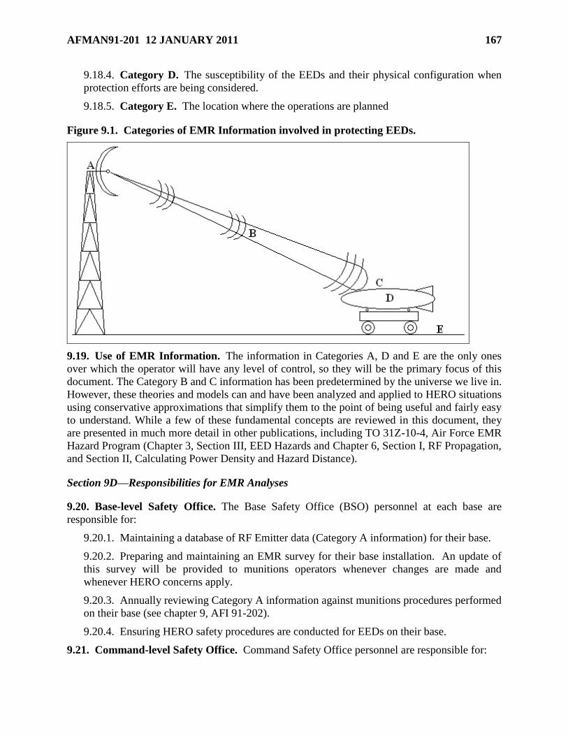
AFMAN91-201 12 JANUARY 2011 167
9.18.4. Category D. The susceptibility of the EEDs and their physical configuration when
protection efforts are being considered.
9.18.5. Category E. The location where the operations are planned
Figure 9.1. Categories of EMR Information involved in protecting EEDs.
9.19. Use of EMR Information. The information in Categories A, D and E are the only ones
over which the operator will have any level of control, so they will be the primary focus of this
document. The Category B and C information has been predetermined by the universe we live in.
However, these theories and models can and have been analyzed and applied to HERO situations
using conservative approximations that simplify them to the point of being useful and fairly easy
to understand. While a few of these fundamental concepts are reviewed in this document, they
are presented in much more detail in other publications, including TO 31Z-10-4, Air Force EMR
Hazard Program (Chapter 3, Section III, EED Hazards and Chapter 6, Section I, RF Propagation,
and Section II, Calculating Power Density and Hazard Distance).
Section 9D—Responsibilities for EMR Analyses
9.20. Base-level Safety Office. The Base Safety Office (BSO) personnel at each base are
responsible for:
9.20.1. Maintaining a database of RF Emitter data (Category A information) for their base.
9.20.2. Preparing and maintaining an EMR survey for their base installation. An update of
this survey will be provided to munitions operators whenever changes are made and
whenever HERO concerns apply.
9.20.3. Annually reviewing Category A information against munitions procedures performed
on their base (see chapter 9, AFI 91-202).
9.20.4. Ensuring HERO safety procedures are conducted for EEDs on their base.
9.21. Command-level Safety Office. Command Safety Office personnel are responsible for:
168 AFMAN91-201 12 JANUARY 2011
9.21.1. Understanding HERO safety procedures for all operations performed by their units.
9.21.2. Providing assistance to base safety and munitions operators when requested.
9.21.3. Distributing updated HERO information to their units when it becomes available.
9.22. Communications Squadron and Installation Spectrum Manager (ISM). The
Communications Squadron personnel and the Installation Spectrum Manager at each base are
responsible for:
9.22.1. Assisting in the collection of Category A Info.
9.22.2. Providing base Safety Offices with RF emitter data (Category A) necessary to
perform EMR Surveys and HERO safety analyses.
9.22.3. Coordinating with the base safety office prior to locating new RF emitters on the
installation.
9.22.4. Coordinating with the base Safety Office prior to relocating RF emitters, or changing
frequency, gain, or power characteristics of existing RF emitters on the installation.
9.22.5. Preparing and maintaining Spectrum Assignment records for their base installation.
A copy of frequency authorizations will be provided to the base Safety Office.
9.23. Headquarters Air Force Safety Center/Weapons Division (AFSC/SEW). Weapons
Safety personnel are responsible for:
9.23.1. Responding to all requests for assistance with the application of safety requirements
in this chapter.
9.23.2. Updating SSD tables and charts when AF safety policies or regulations change.
9.23.3. Checking Federal Communications Commission (FCC) guidance at least quarterly
for changes that might effect MME safety guidance.
9.23.4. Analyzing and distributing information on a case-by-case basis regarding decisions,
approved use guidelines and SSD calculations for MME devices not specifically presented in
this chapter.
9.24. Civil Engineering Office (CE). CE Office personnel at each base are responsible for:
9.24.1. Reporting any plans/efforts to install new emitters to the ISM and Safety Office for
their base.
9.24.2. Reporting any plans/efforts to relocate any existing RF emitters, or change the
frequency, gain, or power characteristics of any existing RF emitters on their base.
9.25. Munitions Squadron/Flight. The Munitions Support Squadron personnel at each base
are responsible for:
9.25.1. Supplying their base Safety Office with current munitions procedures and Category
E information. See paragraph 9.18 for EMR information categories.
9.25.2. Knowing Category D info for all munitions maintained.
9.25.3. Applying Category A Info (from BSO) and Category D information into procedural
planning to ensure EMR safety.
AFMAN91-201 12 JANUARY 2011 169
Section 9E—Emitter Categories and Assumptions
9.26. Traditional Fixed-Location Emitter (TFE) Analysis. The application of radiation
theory and coupling models have historically been based on a few underlying assumptions.
Emitters that meet these key assumptions will be referred to as Traditional Fixed-Location
Emitters (TFEs).
9.26.1. There are two basic assumptions for most RF emitters that need to be considered for
EED safety.
9.26.1.1. The emitters are in a fixed location, usually mounted on a tower, mast or
rooftop.
9.26.1.2. The emitters are radiating a fairly high power level; hundreds if not thousands
of Watts.
9.26.2. These assumptions allow the application of ―far-field‖ approximations to simplify
the radiation theory and coupling models when EMR safety requirements are analyzed. The
resulting EMR safety requirements for EEDs were simplified to the calculation of a ―Safe
Separation Distance (SSD),‖ often hundreds of feet.
9.26.3. The choice of equations used to calculate the SSD for a TFE depends on the HERO
classification of the EED (see paragraph 9.28.1), the frequency of the transmitted RF energy
and the total EIRP of the emitter. Different equations are required for different operations
because safety threshold levels vary depending on the configuration of the EED (see Table
9.1).
9.26.4. If this minimum distance (SSD) is maintained between the EED and the emitter, then
the RF power density at the location of the EED, even under the most optimal transmission
and the most efficient coupling conditions, will be too low to provide sufficient energy to
initiate the EED.
9.26.5. HERO protection for EEDs will continue to follow this approach for TFEs.
9.27. Modern Mobile Emitter (MME) Analysis. The validity of the traditional approach for
SSD determination (see paragraph 9.26) has come under increased scrutiny as the proliferation of
low-power, mobile data and communications systems has undermined the assumptions at the
foundation of that approach.
9.27.1. Cellular phones, Personal Digital Assistants (PDAs), barcode readers, RFID devices,
wireless computers and network access points transmit at much lower power levels than
more conventional emitters (TFEs), but they can also be brought much closer to EEDs, even
into the near field of their antennas.
9.27.2. All low power, mobile emitters, and any low power fixed-location emitters that are
part of the same system, will be referred to as Modern Mobile Emitters (MMEs).
9.27.3. While this is not an entirely new hazard for EEDs, it does require a new approach for
analyzing and calculating SSDs and related safety requirements (see paragraph 9.30).
9.27.4. When unsure of the classification for an emitter, assistance should be requested (see
paragraph 9.32).
170 AFMAN91-201 12 JANUARY 2011
Section 9F—Methods for Protecting EEDs from EMR Hazards
9.28. TFE Safety Procedures for Conventional Weapons and Individual EEDs. The
following steps outline the procedures for insuring the EMR from a Traditional Fixed-location
Emitter does not cause inadvertent EED initiation. This is done by maintaining a Safe
Separation Distance (SSD) between the emitter and the EED.
9.28.1. Preparation and HERO Classification.
9.28.1.1. The following information shall be collected and reviewed prior to performing
any operation involving conventional weapons or individual EEDs.
9.28.1.1.1. The configurations of the EED during the planned operation shall be
determined.
9.28.1.1.2. When available, the susceptibilities of the EED in these configurations
shall be obtained.
9.28.1.1.3. The EME at the location of the planned operations shall be determined.
This information should be available from the ISM or the BSO.
9.28.1.2. Once this information has been collected, the HERO classification applicable to
the EED for the planned operations can be determined as one of the three possibilities
listed below. The EME for EIDs is given in MIL-STD-464C, paragraph 5.9.3. and tables
9 and 10. These HERO designations apply only to the planned operation that was
analyzed. Any change in the operation, the EME or the EED’s configuration will require
reassessment of the HERO classification.
9.28.1.2.1. HERO SAFE. If the EED has been determined, by previously conducted
engineering and scientific analysis, to be incapable of being initiated by EMR in the
planned configuration and the expected EME, the EED shall be classified as HERO
SAFE and no further protection from TFEs is necessary.
9.28.1.2.2. HERO SUSCEPTIBLE. If the EED is vulnerable to possible initiation
by EMR in the planned configuration and the expected EME, the EED shall be
classified as HERO SUSCEPTIBLE and protective efforts are required (see
paragraph 9.28.2.2).
9.28.1.2.3. HERO UNSAFE. If susceptibility data for the EED in the planned
configuration is available and the sensitivities of the EED are less than 54mW MNFP
and/or less than 85mA MNFC, the EED shall be classified as HERO UNSAFE and
additional protective efforts are required (see paragraph 9.28.2.3).
9.28.2. Determining Protection Requirements.
9.28.2.1. For EEDs classified as HERO SAFE no further protection from TFEs is
necessary in its expected EME (for information about protection from MMEs, see
paragraph 9.30).
9.28.2.2. For EEDs classified as HERO SUSCEPTIBLE, an SSD from each known TFE
shall be determined using Table 9.1 and the expected configuration of the EED. The
planned operations must be located at a distance greater than the SSD from each TFE.
AFMAN91-201 12 JANUARY 2011 171
9.28.2.3. For EEDs classified as HERO UNSAFE, assistance shall be requested to
determine the protection requirements necessary (see paragraph 9.32).
9.28.2.4. If any of the calculated SSDs are too large for the planned operations, and if the
specific susceptibility values for the EED are known, a new distance can be calculated
using software available from the Joint Spectrum Center and AFSC/SEW (see paragraph
9.33).
9.28.2.5. Approximate calculations for the safe separation distances for EEDs in
conventional munitions can also be made using the nomographs in Figure 9.2 and Figure
9.4.
9.28.2.6. Additional safety criteria are required if MMEs are present for munitions
regardless of HERO classification. See paragraph 9.30 for guidance.
9.28.2.7. Examples of safe separation distance calculations for TFEs:
9.28.2.7.1. Scenario:
Condition of EED: HERO SUSCEPTIBLE, Exposed
Transmitter frequency = 300 MHz
Average transmitter power = 1000 watts
Antenna gain = 15dB
9.28.2.7.2. Using Table 9.1:
Step 1. Find the proper configuration and formula from Table 9.1.
Since the EED is exposed and the frequency is 300 MHz, the applicable formula is:
ftGPf
625.448D tt
Step 2. Determine PtGt where
Pt = 1000 watts (given),
GdB = 15
Gt = log -1 (GdB/10) = 31.6:
PtGt = (1000) (31.6) = 31,600 Watts
Step 3. Substitute these values into the formula:
ftD 26631600300
625.448
9.28.2.7.3. Using Figure 9.2:
Step 1. Mark the point where 300 MHz lies on the frequency scale.
Step 2. Determine the effective radiated power (ERP) by multiplying PtGt where
Pt = 1000 watts (given)
172 AFMAN91-201 12 JANUARY 2011
Gt = log-1 (GdB/10) = log-1 (15/10) = log-1 1.5 ( or Gt = 31.6):
PtGt = (1000) (31.6) = 31,600 watts.
Mark this spot on the effective radiated power scale.
Step 3. Draw a straight line through the points established in steps 1 and 2 to the distance
scale. (see Figure 9.3) The recommended SSD, about 260 feet, is read where the line
intersects the distance scale.
9.29. TFE Safety Procedures for Nuclear Weapons. The following steps outline the
procedures for insuring the EMR from a Traditional Fixed-location Emitter does not cause
inadvertent EED initiation. This is done by maintaining a Safe Separation Distance (SSD)
between the emitter and the EED.
9.29.1. Preparation/Planning.
9.29.1.1. The following information shall be collected and reviewed prior to performing
any operations involving nuclear weapons.
9.29.1.1.1. The configurations of the nuclear weapon during the planned operation
must be determined.
9.29.1.1.2. The EME at the location of the planned operations shall be determined.
This information should be available from the ISM or the BSO.
9.29.2. Determining Protection Requirements.
9.29.2.1. The SSD from each known TFE shall be determined using Table 9.2 and the
configuration of the weapon. The planned operations must be conducted at locations
greater than the SSD for each TFE.
9.29.2.2. Additional safety criteria are required if MMEs are present. See paragraph 9.30
for guidance.
9.30. MME Safety Procedures and Considerations. If any commercial, common-use
transmitters fitting the category of MMEs are present in the location where EED operations are
planned, the following additional guidelines shall be applied.
9.30.1. Base and Command Safety Offices may require separation distances for individual
categories of MMEs greater than those listed in this paragraph. However, they may not
allow the use of MMEs at distances less than the values listed below without AFSC/SEW
approval (see Section 9H).
9.30.2. General Assumptions. Most of the emitters considered MMEs are governed by the
Federal Communications Commission (FCC) and the Code of Federal Regulations (CFR),
Title 47. Common, commercially obtained sources of RF energy, such as cellular phones,
remote key fobs, etc., are normally governed for emission levels by FCC Part 15 or Part 22
and are identified accordingly. If compliance cannot be ascertained via markings on the
device or within the owner’s/user’s manual, or if the planned operations occur outside
CONUS where FCC regulations are not applicable, assistance should be requested (see
paragraph 9.32).
9.30.3. ―Worst-Case‖ Assumptions. All guidance for MMEs is based on the same ―worst
case‖ assumptions for EED susceptibility; MNFC = 85mA, MNFP = 54mW and an
AFMAN91-201 12 JANUARY 2011 173
additional ―firing consequence factor‖ of -16.5dB. If the EED involved is known to have
susceptibilities below these values or if the MME performance exceeds any of the Pt or Gt
values listed below, assistance should be requested (see paragraph 9.32).
9.30.4. The transmission of modern mobile emitters is not authorized within 10 feet of any
exposed EED, or any weapon system containing an EED except for those items specifically
listed below and those specific items that have been individually researched and addressed in
writing by AFSC/SEW. When a lesser distance is allowed, MMEs should still be kept at
least 10 feet away whenever possible. Using any emitter closer than 10 feet should only take
place if required for the proper use of the transmitting device or if required to complete the
planned and approved operations, and is not justified by issues of convenience or for the sole
purpose of ease of operations.
9.30.4.1. Cellular telephones. The SSD for all cellular telephones is 10 ft from all
EEDs, regardless of configuration. This guidance assumes all cellular phones are in
compliance with Title 47 CFR 22.905 which defines the allowable frequency range for
cellular phones as 824 MHz to 849 MHz and Title 47 CFR 22.913 which requires a
maximum equivalent isotropically radiated power (EIRP) of 7 Watts.
9.30.4.2. Radio Frequency Identification/Automatic Identification Technology
(RFID/AIT) Devices. All HERO issues for RFID and AIT devices are being addressed
by the Product Manager Joint-Automatic Identification Technology Office (PM J-AIT).
The PM J-AIT is HERO certifying RFID and AIT equipment for near field operation
using ―worst case‖ guidance limitations. All SSDs calculated, approved and published by
PM J-AIT for individual pieces of equipment applicable to munitions operations may be
considered approved and shall be observed. Contact AFSC/SEWN for a current list of
approved AIT devices.
9.30.4.3. Wireless Computer Network Equipment. The SSD for all wireless
equipment is 2.5 ft from all EEDs, regardless of configuration. This guidance assumes
all wireless computer network cards, wireless network access points, personal digital
assistants, and any other similar devices present are in compliance with Title 47 CFR
15.247 which requires all wireless equipment has a maximum EIRP of 4 Watts,
transmission is at or above 2.4GHz, and antennas have a maximum gain of 6dBi.
9.30.4.4. Remote Keyless Entry Devices. The SSD for all remote keyless entry devices
(also known as ―key fobs‖) is 0.5 ft from all EEDs, regardless of configuration. This
guidance assumes all these devices are in compliance with Title 47 CFR 15.231.
9.30.5. If the operator is unsure if a device should be defined as an MME or if the operator
has an MME device of a type not specifically addressed in this section, assistance should be
requested (see paragraph 9.32). AFSC/SEW will analyze and distribute information
regarding decisions, approved use guidelines and SSD calculations for specific devices on a
case-by-case basis.
9.31. Maximum Power Density Criteria. When the minimum safe separation distances cannot
be achieved, because of lack of real estate or any other limitations, a power density and field
intensity survey should be made at the location where the operations are planned to occur.
9.31.1. Compare the measured power density with the recommended maximum power
density calculated from Table 9.1 for conventional munitions or Table 9.2 for nuclear
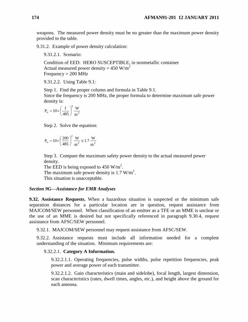
174 AFMAN91-201 12 JANUARY 2011
weapons. The measured power density must be no greater than the maximum power density
provided in the table.
9.31.2. Example of power density calculation:
9.31.2.1. Scenario:
Condition of EED: HERO SUSCEPTIBLE, in nonmetallic container
Actual measured power density = 450 W/m2
Frequency = 200 MHz
9.31.2.2. Using Table 9.1:
Step 1. Find the proper column and formula in Table 9.1.
Since the frequency is 200 MHz, the proper formula to determine maximum safe power
density is:
2
2
om
W
485
f10P
Step 2. Solve the equation:
22
2
om
W7.1
m
W
485
20010P
Step 3. Compare the maximum safety power density to the actual measured power
density.
The EED is being exposed to 450 W/m2.
The maximum safe power density is 1.7 W/m2.
This situation is unacceptable.
Section 9G—Assistance for EMR Analyses
9.32. Assistance Requests. When a hazardous situation is suspected or the minimum safe
separation distances for a particular location are in question, request assistance from
MAJCOM/SEW personnel. When classification of an emitter as a TFE or an MME is unclear or
the use of an MME is desired but not specifically referenced in paragraph 9.30.4, request
assistance from AFSC/SEW personnel.
9.32.1. MAJCOM/SEW personnel may request assistance from AFSC/SEW.
9.32.2. Assistance requests must include all information needed for a complete
understanding of the situation. Minimum requirements are:
9.32.2.1. Category A Information.
9.32.2.1.1. Operating frequencies, pulse widths, pulse repetition frequencies, peak
power and average power of each transmitter.
9.32.2.1.2. Gain characteristics (main and sidelobe), focal length, largest dimension,
scan characteristics (rates, dwell times, angles, etc.), and height above the ground for
each antenna.
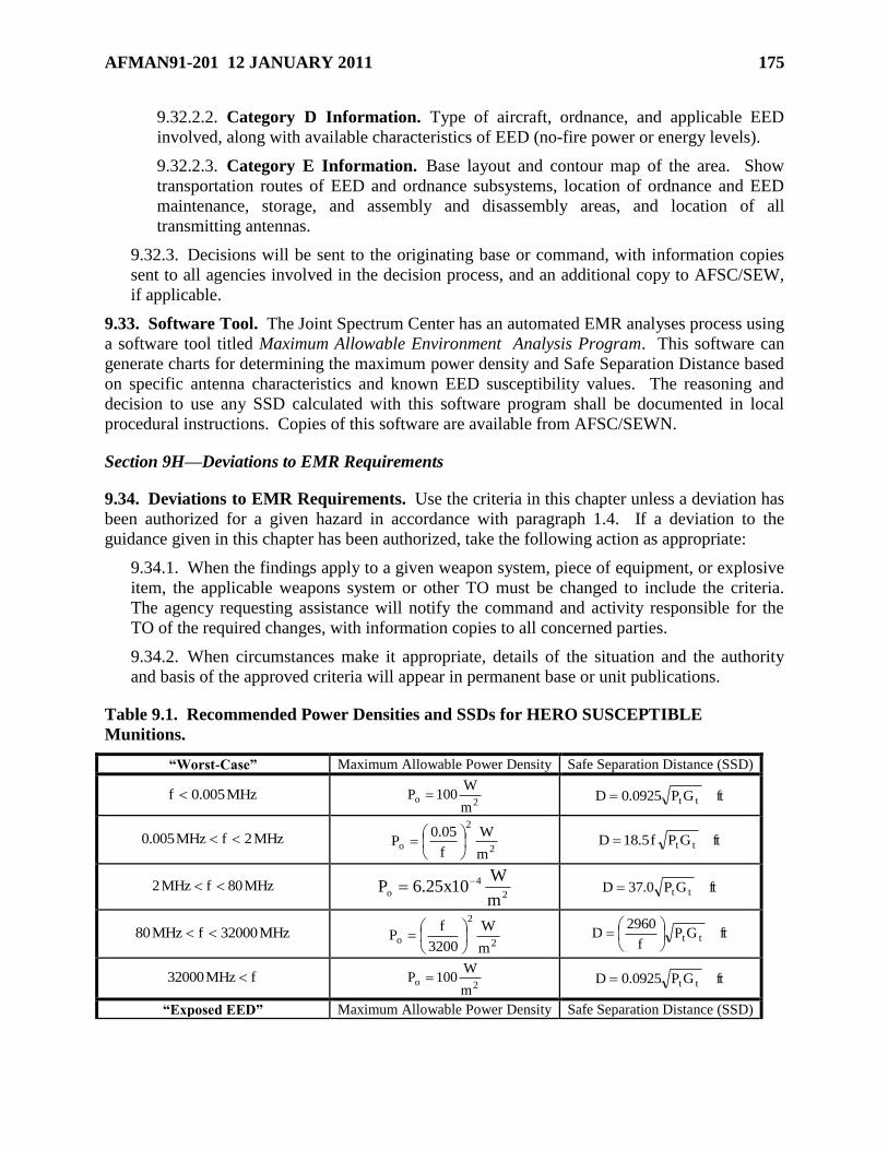
AFMAN91-201 12 JANUARY 2011 175
9.32.2.2. Category D Information. Type of aircraft, ordnance, and applicable EED
involved, along with available characteristics of EED (no-fire power or energy levels).
9.32.2.3. Category E Information. Base layout and contour map of the area. Show
transportation routes of EED and ordnance subsystems, location of ordnance and EED
maintenance, storage, and assembly and disassembly areas, and location of all
transmitting antennas.
9.32.3. Decisions will be sent to the originating base or command, with information copies
sent to all agencies involved in the decision process, and an additional copy to AFSC/SEW,
if applicable.
9.33. Software Tool. The Joint Spectrum Center has an automated EMR analyses process using
a software tool titled Maximum Allowable Environment Analysis Program. This software can
generate charts for determining the maximum power density and Safe Separation Distance based
on specific antenna characteristics and known EED susceptibility values. The reasoning and
decision to use any SSD calculated with this software program shall be documented in local
procedural instructions. Copies of this software are available from AFSC/SEWN.
Section 9H—Deviations to EMR Requirements
9.34. Deviations to EMR Requirements. Use the criteria in this chapter unless a deviation has
been authorized for a given hazard in accordance with paragraph 1.4. If a deviation to the
guidance given in this chapter has been authorized, take the following action as appropriate:
9.34.1. When the findings apply to a given weapon system, piece of equipment, or explosive
item, the applicable weapons system or other TO must be changed to include the criteria.
The agency requesting assistance will notify the command and activity responsible for the
TO of the required changes, with information copies to all concerned parties.
9.34.2. When circumstances make it appropriate, details of the situation and the authority
and basis of the approved criteria will appear in permanent base or unit publications.
Table 9.1. Recommended Power Densities and SSDs for HERO SUSCEPTIBLE
Munitions.
―Worst-Case‖ Maximum Allowable Power Density Safe Separation Distance (SSD)
MHz005.0f 2o
m
W100P ftGP0925.0D tt
MHz2fMHz005.0 2
2
om
W
f
05.0P
ftGPf5.18D tt
MHz80fMHz2 2
4
om
W10x25.6P ftGP0.37D tt
MHz32000fMHz80 2
2
om
W
3200
fP
ftGP
f
2960D tt
fMHz32000 2o
m
W100P ftGP0925.0D tt
―Exposed EED‖ Maximum Allowable Power Density Safe Separation Distance (SSD)
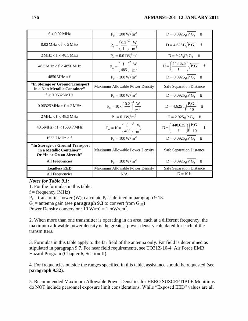
176 AFMAN91-201 12 JANUARY 2011
MHz02.0f 2o mW100P ftGP0925.0D tt
MHz2fMHz02.0 2
2
om
W
f
2.0P
ftGPf625.4D tt
MHz5.48fMHz2 2o mW01.0P ftGP25.9D tt
MHz4850fMHz5.48 2
2
om
W
485
fP
ftGP
f
625.448D tt
fMHz4850 2o mW100P ftGP0925.0D tt
―In Storage or Ground Transport
in a Non-Metallic Container‖ Maximum Allowable Power Density Safe Separation Distance
MHz06325.0f 2o mW100P ftGP0925.0D tt
MHz2fMHz06325.0 2
2
om
W
f
2.010P
ft
10
GPf625.4D tt
MHz5.48fMHz2 2o mW1.0P ftGP925.2D tt
MHz7.1533fMHz5.48 2
2
om
W
485
f10P
ft
10
GP
f
625.448D tt
fMHz7.1533 2o mW100P ftGP0925.0D tt
―In Storage or Ground Transport
in a Metallic Container‖
Or ―In or On an Aircraft‖
Maximum Allowable Power Density Safe Separation Distance
All Frequencies 2o mW100P ftGP0925.0D tt
Leadless EED Maximum Allowable Power Density Safe Separation Distance
All Frequencies N/A ft10D
Notes for Table 9.1: 1. For the formulas in this table:
f = frequency (MHz)
Pt = transmitter power (W); calculate Pt as defined in paragraph 9.15.
Gt = antenna gain (see paragraph 9.3 to convert from GdB)
Power Density conversion: 10 W/m2 = 1 mW/cm
2.
2. When more than one transmitter is operating in an area, each at a different frequency, the
maximum allowable power density is the greatest power density calculated for each of the
transmitters.
3. Formulas in this table apply to the far field of the antenna only. Far field is determined as
stipulated in paragraph 9.7. For near field requirements, see TO31Z-10-4, Air Force EMR
Hazard Program (Chapter 6, Section II).
4. For frequencies outside the ranges specified in this table, assistance should be requested (see
paragraph 9.32).
5. Recommended Maximum Allowable Power Densities for HERO SUSCEPTIBLE Munitions
do NOT include personnel exposure limit considerations. While ―Exposed EED‖ values are all
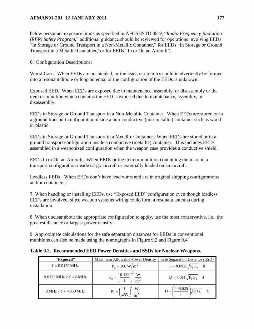
AFMAN91-201 12 JANUARY 2011 177
below personnel exposure limits as specified in AFOSHSTD 48-9, ―Radio Frequency Radiation
(RFR) Safety Program,‖ additional guidance should be reviewed for operations involving EEDs
―In Storage or Ground Transport in a Non-Metallic Container,‖ for EEDs ―In Storage or Ground
Transport in a Metallic Container,‖or for EEDs ―In or On an Aircraft‖.
6. Configuration Descriptions:
Worst-Case. When EEDs are unshielded, or the leads or circuitry could inadvertently be formed
into a resonant dipole or loop antenna, or the configuration of the EEDs is unknown.
Exposed EED. When EEDs are exposed due to maintenance, assembly, or disassembly or the
item or munition which contains the EED is exposed due to maintenance, assembly, or
disassembly.
EEDs in Storage or Ground Transport in a Non-Metallic Container. When EEDs are stored or in
a ground transport configuration inside a non-conductive (non-metallic) container such as wood
or plastic.
EEDs in Storage or Ground Transport in a Metallic Container. When EEDs are stored or in a
ground transport configuration inside a conductive (metallic) container. This includes EEDs
assembled in a weaponized configuration when the weapon case provides a conductive shield.
EEDs In or On an Aircraft. When EEDs or the item or munition containing them are in a
transport configuration inside cargo aircraft or externally loaded on an aircraft.
Leadless EEDs. When EEDs don’t have lead wires and are in original shipping configurations
and/or containers.
7. When handling or installing EEDs, use ―Exposed EED‖ configuration even though leadless
EEDs are involved, since weapon systems wiring could form a resonant antenna during
installation.
8. When unclear about the appropriate configuration to apply, use the most conservative, i.e., the
greatest distance or largest power density.
9. Approximate calculations for the safe separation distances for EEDs in conventional
munitions can also be made using the nomographs in Figure 9.2 and Figure 9.4
Table 9.2. Recommended EED Power Densities and SSDs for Nuclear Weapons.
―Exposed‖ Maximum Allowable Power Density Safe Separation Distance (SSD)
MHz0132.0f 2o mW100P ftGP0925.0D tt
MHz8fMHz0132.0 2
2
om
W
f
132.0P
ftGPf01.7D tt
MHz4850fMHz8 2
2
om
W
485
fP
ftGP
f
625.448D tt
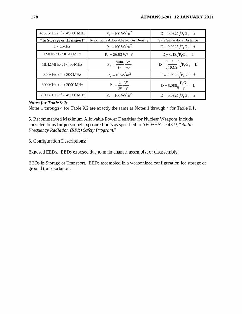
178 AFMAN91-201 12 JANUARY 2011
MHz45000fMHz4850 2o mW100P ftGP0925.0D tt
―In Storage or Transport‖ Maximum Allowable Power Density Safe Separation Distance
MHz1f 2o mW100P ftGP0925.0D tt
MHz42.18fMHz1 2o mW53.26P ftGP18.0D tt
MHz30fMHz42.18 22o
m
W
f
9000P ftGP
5.102
fD tt
MHz300fMHz30 2o mW10P ftGP2925.0D tt
MHz3000fMHz300 2o
m
W
30
fP ft
f
GP066.5D tt
MHz45000fMHz3000 2o mW100P ftGP0925.0D tt
Notes for Table 9.2: Notes 1 through 4 for Table 9.2 are exactly the same as Notes 1 through 4 for Table 9.1.
5. Recommended Maximum Allowable Power Densities for Nuclear Weapons include
considerations for personnel exposure limits as specified in AFOSHSTD 48-9, ―Radio
Frequency Radiation (RFR) Safety Program.‖
6. Configuration Descriptions:
Exposed EEDs. EEDs exposed due to maintenance, assembly, or disassembly.
EEDs in Storage or Transport. EEDs assembled in a weaponized configuration for storage or
ground transportation.
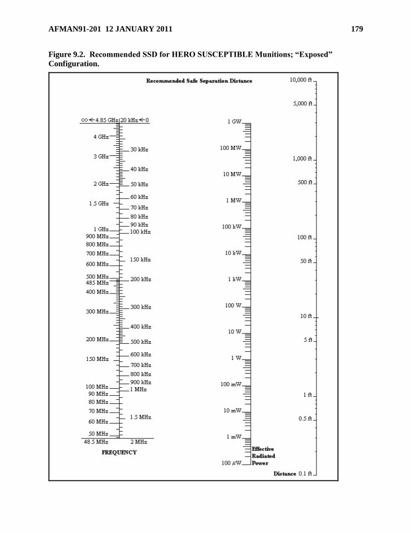
AFMAN91-201 12 JANUARY 2011 179
Figure 9.2. Recommended SSD for HERO SUSCEPTIBLE Munitions; ―Exposed‖
Configuration.
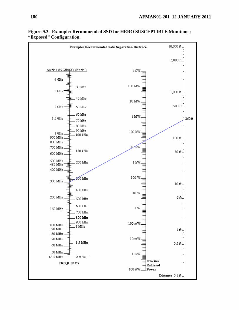
180 AFMAN91-201 12 JANUARY 2011
Figure 9.3. Example: Recommended SSD for HERO SUSCEPTIBLE Munitions;
―Exposed‖ Configuration.
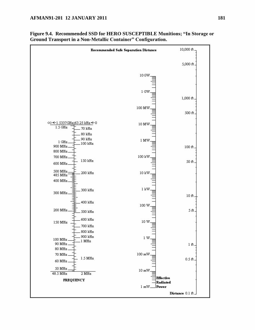
AFMAN91-201 12 JANUARY 2011 181
Figure 9.4. Recommended SSD for HERO SUSCEPTIBLE Munitions; ―In Storage or
Ground Transport in a Non-Metallic Container‖ Configuration.
182 AFMAN91-201 12 JANUARY 2011
Chapter 10
FIREFIGHTING, EMERGENCY PLANNING AND FIRE PREVENTION
Section 10A—Hazard Identification for Firefighting and Emergency Planning
10.1. Scope and Applicability.
10.1.1. This section establishes standard firefighting hazard identification measures to ensure
a minimum practicable risk in fighting fires involving AE. These identification measures are
based on the classification of AE fires into four fire divisions according to their predominant
hazard.
10.1.2. AE hazard symbols and supplemental symbols including chemical agent symbols
(see paragraph 10.4) are for firefighting situations.
10.2. Fire Divisions. There are four fire divisions. Fire division 1 indicates the greatest hazard.
The hazard decreases with ascending fire division numbers from 1 to 4, and are related to HD as
shown in Table 10.1. The hazard is based on the burning or explosives characteristics of the
material. Fire symbols do not apply to liquid propellants, except for symbol 1, which is used to
indicate a detonation hazard of Group IV propellant. Fire protection for insensitive high
explosives (both bulk and filled items) is based on their equivalent storage classification.
10.3. Fire Division Symbols.
10.3.1. The four fire divisions are represented by four distinctive symbols so that firefighting
personnel can recognize the hazards. A fire division number is shown on each symbol. For
the purpose of identifying these symbols from long range, the symbols differ in shape as
shown in Figure 10.1.
10.3.2. The shape and dimensions of the symbols are shown in Figure 10.1. This shape and
color scheme is consistent with the requirements of the North Atlantic Treaty Organization
(NATO), United Nations Organization (UNO), and International Maritime Organization
(IMO).
10.4. Chemical Agent and Chemical Munition Hazard Symbols.
10.4.1. The storage of chemical agents and chemical munitions requires the use of chemical
hazard symbols. These symbols (see Figures 10.2 and 10.3) will be used in conjunction with
fire symbols, where appropriate. Some of the common chemical agents used in AE, the CG
of that AE, and the chemical hazard symbols required in storage are specified in Table 10.2.
10.4.2. The following sections describe these symbols, the hazards indicated by the symbols,
and the recommended protective clothing and equipment to be used for fighting fires
involving these chemical agents and chemical munitions. Where respiratory protection
(SCBA and protective masks) are used, personnel must implement a workplace respiratory
protection program IAW AFOSH Std 48-137, Respiratory Protection Program. (Reference
the item T.O., or contact Bioenvironmental Engineering for protective clothing requirements
for situations other than firefighting. The self-contained breathing apparatus (SCBA) and
other protective clothing and equipment prescribed in this paragraph must be used if required
for use by other applicable technical orders or other Department of Defense or Air Force
AFMAN91-201 12 JANUARY 2011 183
publications. See AFI 10-2501, Air Force Emergency Management (EM) Program Planning
and Operations for further guidance.)
10.4.2.1. Set 1 of Chemical Hazard Symbol 1 requires full protective clothing (see
Figure 10.2 and Table 10.2) and indicates the presence of highly toxic chemical agents
that may cause death or serious damage to body functions. The following full protective
clothing will be used: Level A encapsulating suit IAW T.O. 14P3-1-7, Toxicological
Protective Apron, M-2.
10.4.2.1.1. SCBA.
10.4.2.1.2. Impermeable suit.
10.4.2.1.3. Impermeable hood.
10.4.2.1.4. Impermeable boots.
10.4.2.1.5. Impermeable undergarments.
10.4.2.1.6. Impermeable coveralls.
10.4.2.1.7. Impermeable protective footwear.
10.4.2.1.8. Impermeable gloves.
10.4.2.2. Set 2 of Chemical Hazard Symbol 1 requires full protective clothing (see
Figure 10.2 and Table 10.2) and indicates the presence of harassing agents (riot control
agents and smokes). The following protective clothing will be used:
10.4.2.2.1. Protective gas masks or SCBA.
10.4.2.2.2. Permeable coveralls.
10.4.2.2.3. Protective gloves.
10.4.2.2.4. Firefighting personnel equipped with normal heat-resistant clothing (e.g.,
bunker suit) and gas mask or SCBA do not require the set 2 protective clothing.
10.4.2.3. Set 3 of Chemical Hazard Symbol 1 requires full protective clothing (see
Figure 10.2 and Table 10.2) and indicates the presence of white phosphorous (WP) or
other spontaneously combustible material. The following protective clothing will be
used:
10.4.2.3.1. Protective gas masks or SCBA.
10.4.2.3.2. Flameresistant coveralls.
10.4.2.3.3. Flameresistant gloves.
10.4.2.3.4. Firefighting personnel equipped with normal heat-resistant clothing (e.g.,
bunker suit) and gas mask or SCBA do not require the set 3 protective clothing.
10.4.2.4. Chemical Hazard Symbol 2 requires the wearing of breathing apparatus (see
Figure 10.2 and Table 10.2) and indicates the presence of incendiary or readily
flammable chemical agents that present an intense radiant heat hazard. Protective masks
will be used to prevent inhalation of smoke from burning incendiary mixtures.
184 AFMAN91-201 12 JANUARY 2011
10.4.2.5. Chemical Hazard Symbol 3 warns against applying water (see Figure 10.2 and
Table 10.2) and indicates a dangerous reaction will occur if water is used in an attempt to
extinguish fire.
10.5. Obtaining Firefighting Symbol Decals. Decals for fire and chemical hazard symbols
may be obtained through normal Air Force supply channels. National stock numbers (NSN) of
standard and half-size decals are listed in Figures 10.1, 10.2 and 10.3. Make backing for fire
symbol decals the shape of the decal and out of non-combustible material. If heat from the fire
burns off the numbers, the fire department can act on the shape. AFVA 91-216, USAF
Explosives Fire and Chemical Hazard Symbols, is available through publication channels.
Section 10B—Posting Firefighting Symbols
10.6. Purpose of Posting Firefighting Symbols. Firefighting symbols are used as a back-up
precaution for alerting response personnel to explosives or chemicals present. Firefighting
symbols posted on nuclear, chemical, or conventional weapon storage sites will comply with
paragraph 10.7, unless otherwise directed by the Base Fire Chief (direction must be in writing).
These written directions notify personnel that local conditions (e.g., security considerations) may
make it undesirable to identify munitions with fire symbols at the actual storage locations.
10.7. Posting Requirements for Firefighting Symbols.
10.7.1. Post the fire symbol and chemical symbol that applies to the most hazardous material
present at non-nuclear explosives locations.
10.7.2. When non-class 1 hazardous items or materials are stored or used in a facility,
without other items of class 1, identify the predominant hazard to guide emergency response
personnel. In this case, placards are required in accordance with NFPA and OSHA
regulations. (Do not display NFPA and OSHA placards concurrently with class 1 fire
symbols.)
10.7.3. Post firefighting symbols when AE or chemical agents are placed in a facility or
location, and remove the symbols when the AE or chemical agents are removed. The person
in charge of the operation is responsible for posting or changing the symbols.
10.7.4. Notify the Emergency Communication Center (ECC) each time firefighting symbols
are changed.
10.7.5. Half-sized symbols may be used on doors or lockers inside buildings.
10.7.6. Licensed Explosives Storage Locations.
10.7.6.1. Post symbols on exterior and interior entrances to small rooms licensed for
storing AE.
10.7.6.2. Post symbols on lockers or containers licensed for storing AE.
10.7.6.3. Posting symbols on the exterior of buildings containing licensed storage
locations are optional, provided the Base Fire Chief approves in writing. When posted,
ensure symbols are visible from all approach roads.
10.7.7. Non-Flightline Sited Explosives Locations.
10.7.7.1. Ensure symbols are visible from all approach roads.
AFMAN91-201 12 JANUARY 2011 185
10.7.7.2. When one symbol applies to all AE within a storage area or on a service road, it
may be posted at the entry control point or row entrance.
10.7.7.3. Post individual symbols on each door of a multicube storage magazine. Post
the symbol for the highest hazard and applicable sets to be visible from all approach
roads.
10.7.8. Flightline Sited Explosives Locations.
10.7.8.1. Identify aircraft loaded with non-nuclear weapons with symbols posted at each
aircraft or aircraft shelter.
10.7.8.2. One fire symbol may be posted at the entry point (point of entry for fire-
fighting personnel) to an aircraft area.
10.7.8.3. Notify the ECC when each aircraft is loaded or unloaded. Give aircraft parking
location and type of explosives involved.
10.7.8.4. During mass loading of three or more aircraft, when a fire truck is present,
notify the ECC as soon as the last loading is complete.
10.8. Exceptions to Posting Firefighting Symbols.
10.8.1. Locations with aircraft having only exempted devices according to paragraph 12.47.
This exception does not apply to explosives cargo.
10.8.2. Missile sites with a single type of weapon system, such as ICBM sites.
10.8.3. Locations with 1,000 rounds or less of HD 1.4 small arms ammunition.
10.8.4. When, by agreement, host nation symbols are used.
10.8.5. When the responsible commander temporarily orders them removed for emergency
security purposes.
10.8.6. Locations storing or maintaining nuclear weapons or both nuclear and non-nuclear
weapons. Maintain a map or listing of munitions locations. Use line numbers or symbols
from T.O. 11N-20-11, General Firefighting Guidance, for nuclear weapons. Provide this
information to the Fire Department. Update as changes occur.
10.8.7. Aircraft loaded with nuclear weapons or with non-nuclear and nuclear weapons
within the same designated area.
10.8.8. Aircraft in a designated explosives parking area if described in a local publication.
Include the class/division, governing symbol, emergency procedures and the requirement to
notify the Fire Department.
Section 10C—Firefighting Measures and Withdrawal Distances
10.9. Firefighting Measures.
10.9.1. Fires involving conventional munitions cannot be definitized to any one set of
circumstances and environmental conditions. This precludes development of reliable
standardized test criteria and reliable specific item fire fighting and withdrawal times. The
conclusion to be reached from available data is that a munitions reaction to fire is a function
of case thickness and type of explosive filler which can be varied by environmental
186 AFMAN91-201 12 JANUARY 2011
conditions. Since the circumstances of a fire cannot be predicted, specific item by item fire
fighting and withdrawal times cannot be determined with any degree of reliability.
10.9.2. Firefighters shall have a thorough knowledge of the hazards associated with AE fires
and expected AE reactions. The firefighting forces and other essential personnel will be
briefed before approaching the scene of the fire. They will be informed of the known
hazards and conditions existing at the fire scene prior to proceeding to the fire location.
10.9.3. Fires involving AE will be fought according to the HD, fire division, the progression
of the fire, and the procedures specified in this Manual.
10.9.4. All fires starting in the vicinity of ammunition or explosives shall be reported and
fought immediately with all available means to prevent the spreading of fire and munitions
involvement. However, if fire engulfs explosives material or is supplying heat to it, or if the
fire is so large that it cannot be extinguished with the equipment on hand, personnel involved
shall evacuate and seek safety. See table 10.1 for additional information and when required,
evacuate personnel per paragraph 10.10.
10.10. Fire Withdrawal Distances. Commanders are responsible for developing evacuation
plans that include the applicable withdrawal distances as part of the installation’s emergency
planning (see paragraph 10.13).
10.10.1. Non-essential personnel. These emergency withdrawal distances apply in
emergency situations only and are not to be used for facility explosives siting.
10.10.1.1. The initial withdrawal distance for non-essential personnel will be at least
IBD for the PES involved. If the fire involves AE, AE involvement is imminent, or the
fire is or may become uncontrollable, then use the fire withdrawal distances listed in
Table 10.3. The fire withdrawal distances depend on fire involvement and on whether or
not the HD, fire division and quantity of explosives are known.
10.10.1.2. Structures or protected locations offering equivalent protection for the
distances in Table 10.3 may be used in lieu of relocating personnel from the structure or
location to the specified fire withdrawal distance.
10.10.2. Essential personnel. Emergency authorities on-site will determine who qualify as,
and the withdrawal distance for, essential personnel at accidents.
10.10.3. Chemical Agents. AE containing both explosives and chemical agents (see Table
10.2) requires special attention and precautions in firefighting. Fires involving such AE will
be fought in accordance with their fire division characteristics. Responding personnel must
consider the additional hazards and precautions for the chemical agents involved.
10.10.4. Underground Explosives Facilities. Entry to underground explosives facilities
following a fire or explosion requires special precautions. Emergency personnel will monitor
for the presence of toxic fumes or oxygen depleted atmospheres, and will evaluate structural
damage during initial entry following an accident. Commanders will develop written
procedures that define actions in such emergency situations (see paragraph 10.13).
10.10.5. Nuclear Weapons. Nuclear weapons fire withdrawal distances are listed in T.O.
11N-20-11, General Fire Fighting Guidance.
AFMAN91-201 12 JANUARY 2011 187
10.11. Improvised Explosive Device Withdrawal Distances. Withdraw all non-essential
personnel in accordance with AFPAM 10-100, Airman’s Manual. Personnel shall be behind or
under cover. Withdraw to the following MINIMUM distances: 500 feet if the IED is a small
item or box (up to 2 cu ft), 1,000 feet if the IED is a barrel or car (up to 15 cu ft), 1,500 feet if the
IED is a van or truck, or 2,000 feet and beyond if the IED is a vehicle larger than already
described. Responding command authorities and EOD teams will evaluate and adjust these
distances if needed. Distances are for initial evacuation until command authorities and EOD
teams evaluate the incident.
10.12. Withdrawal Distances for AE Not Involved in Fire. The initial decision to evacuate
non-essential personnel will be based on the type of AE involved and its susceptibility to become
more unstable, armed, or hazardous. Good judgment, with regards to protecting personnel from
the hazards of the AE or surrounding area, must be exercised. When evacuation is considered
necessary, or is required by other technical guidance, clear the area to a distance of 300 feet (125
feet for simulators and smoke producing devices). Withdrawal distances may be adjusted by the
incident commander.
Section 10D—Emergency Planning
10.13. Emergency Planning. Commanders will develop an emergency management plan
designed to provide safety, security, and environmental protection for accidents involving AE.
Plans will be coordinated with the applicable federal, state, and local emergency response
authorities (e.g., law enforcement, fire departments, hospitals, etc.) and any established Local
Emergency Planning Committees (LEPC). In addition to requirements prescribed in AFI 10-
2501, Air Force Emergency Management (EM) Program Planning and Operations, the plan will
include the following:
10.13.1. Specific sections and guidance that address withdrawal distances, emergency
preparedness, contingency planning, and security. The developed EM plan will limit access
to accident sites to trained and authorized personnel.
10.13.2. Procedures that minimize the possibility of an unpermitted or uncontrolled
detonation, release, discharge, or migration of AE out of any storage unit when such
release, discharge, or migration may endanger human health or the environment.
10.13.3. Provisions for prompt notification (to include withdrawal distances) to emergency
response and environmental agencies and the potentially affected public for an actual or
potential detonation or uncontrolled release, discharge, or migration of AE that may endanger
human health or the environment.
10.13.4. Provisions for complying with the Emergency Planning Community Right-To-
Know Act (EPCRA) and Air Force implementing policies.
10.13.5. Each unit and installation fire protection agency with AE storage and operations
must develop pre-fire plans as prescribed by AFI 32-2001, Fire Emergency Services
Program. Include all AE locations and operations, to include licensed explosives storage
locations.
10.13.6. Each ECC will have an area map or computer-generated display showing all AE
locations and operations and their firefighting symbols, to include licensed explosives storage
188 AFMAN91-201 12 JANUARY 2011
locations. This map must also show adjacent facilities at risk from explosives. Whenever
possible, ensure all sites have a CE real property identification number.
10.14. Fire Drills. Drills are conducted to train firefighting forces and unit personnel, and to
ensure all other personnel involved understand their duties. They are also conducted to evaluate
fire alarm systems, firefighting equipment, and evacuation procedures.
10.14.1. Fire drills will be held within the explosives storage area at intervals not to exceed 6
months.
10.14.2. Coordinate fire drills with the Base Fire Chief if a Fire Department response is
involved. This does not preclude unannounced drills of a Fire Department's response
capabilities, provided coordination with the Base Fire Chief is accomplished at least 30
minutes before starting the drill.
10.14.3. Personnel responsible for conducting drills will ensure all involved are aware that
the drill is an exercise, and not an actual fire.
Section 10E—Fire Prevention
10.15. Heat-Producing Devices. In any explosives area, use devices that produce temperatures
higher than 228o F (109o C) temporarily and only when essential. Develop written safety
procedures for these devices and include details on the location, purpose, and duration of use.
Coordinate the procedures through the installation safety office and the Fire Department for
approval. Properly installed, approved furnaces and electrical space heaters are exempt. Heat-
producing devices are not allowed where exposed explosives are present. Ensure personnel are
qualified on the equipment prior to use.
10.16. Vegetation Control. The primary purpose of vegetation control is to limit the
probability of combustible vegetation catching fire and to slow the spread of vegetation fires.
10.16.1. Except for firebreaks, maintain grounds in or near explosives storage areas or
operating locations according to AFI 32-7064, Integrated Natural Resources. Limit
maintenance on these grounds to that which is necessary to prevent erosion or other waste of
natural resources.
10.16.2. Balance the level of vegetation control with operational factors, such as cost to
control, security, erosion prevention, and passive defense (camouflage).
10.16.3. Use varieties of vegetation that are resistant to burning where feasible.
10.16.4. Do not use herbicides or soil sterilants if complete removal of vegetation will tend
to cause soil erosion.
10.16.5. Do not allow dead or cut vegetation to accumulate.
10.16.6. When animals are used for vegetation control on barricade surfaces and igloo earth
cover, avoid overgrazing to prevent erosion.
10.17. Firebreaks. Where environmental and security factors allow, maintain 50-foot
firebreaks around each PES except for ECMs. Maintain 5 feet around ECM ventilators.
10.18. Controlled Burning. The Base Fire Chief approves and provides oversight for
controlled burning of vegetation.
AFMAN91-201 12 JANUARY 2011 189
10.18.1. Do not conduct controlled burning within 200 feet of any explosives location.
10.18.2. Close windows, doors and ventilators of facilities containing explosives within 600
feet of burning operations.
10.18.3. All controlled burns will be accomplished according to approved, site specific burn
plans. See AFI 32-7064, Integrated Natural Resources Management for additional
information.
10.18.4. The Base Fire Chief determines firefighting personnel and equipment to be present
during burning operations.
10.19. Flammable Liquids for Cleaning. Do not use flammable liquids for cleaning purposes
within an explosives area or near explosives, except as authorized by T.O. Confine use to
specific designated work areas. In-use stocks may not exceed a one-day supply. Store in
approved safety containers or dispensers.
10.20. Paint and Other Flammable Materials. The following guidance applies when using
paint and other flammable materials in AE locations.
10.20.1. Comply with AFOSH Standard 91-501, Air Force Consolidated Occupational
Safety Standard. Store flammable materials in approved flammable storage cabinets, as
required.
10.20.2. Small quantities of flammable materials, such as paints, lubricants and solvents,
required to support explosives maintenance operations may be stored in explosives operating
locations as required. This storage must not be the primary purpose of the area. Incidental
storage of flammable materials not supporting explosives maintenance operations may be
authorized within 50 feet of explosives operating locations. Fire department officials shall be
consulted prior to establishing flammable storage areas in or near explosives operating
locations.
10.20.3. Do not store materials that add fuel sources (such as wood, paper, and rags) with
flammable materials.
10.20.4. Open containers of flammable materials only when in use.
10.20.5. For outdoor storage, place flammable materials in weatherproof containers.
10.20.6. Locate flammable storage locations at least 50 feet from explosives locations or
isolate flammable storage by standard fire walls approved for the type and quantity of
flammables being stored.
10.20.7. Make available at least one fire extinguisher with a rating suitable for the type of
material involved within the distance prescribed by AFOSH 91-501.
10.21. Operating Support Equipment. The following guidance applies when operating
support equipment (not including vehicles powered by internal combustion engines in AE
locations.)
10.21.1. Separation Distances.
10.21.1.1. Locate equipment at least 25 feet from AE. Equipment may be closer
provided adequate ventilation and a fire-resistant dividing wall are provided.
190 AFMAN91-201 12 JANUARY 2011
10.21.1.2. Place aircraft ground support equipment as far away from AE as the length of
the power cord, the length of the hose, or other equipment limitation will allow or as
directed by applicable T.O.
10.21.2. Equipment designed into and installed as part of an operating or storage facility is
exempt from paragraph 10.21.1.
10.21.3. Operations in hardened aircraft shelters are exempt from paragraph 10.21.1
10.21.4. Do not refuel equipment within 100 feet of AE.
10.22. Stacking Combustible Material. The following guidance applies when stacking
combustible material in AE locations.
10.22.1. Stack containers, dunnage, lumber and so forth in an orderly manner.
10.22.2. Keep stacks stable and separated as far as practical from operations.
10.22.3. Limit stacks to 9,000 cubic feet.
10.22.4. Do not place bulk stacks of combustible materials closer than 100 feet from AE
locations.
10.22.5. If necessary, stack working quantities in the vicinity of AE. Remove all of the
material upon completion of the operation or at intervals that prevent hazardous
accumulation.
10.22.6. Provide suitable fire protection equipment.
10.22.7. When needed to prepare for combat operations, temporarily stack in or near the AE
storage site those empty containers, dunnage, and lumber that cannot be removed while the
work is in progress.
10.23. Fire Extinguishers. Unless otherwise directed by the Base Fire Chief, provide a
minimum of two serviceable fire extinguishers, suitable for the hazards involved, for immediate
use at any location where AE is being handled, except as noted.
10.23.1. See paragraph 11.7.8 for licensed explosives storage locations.
10.23.2. Provide each explosives-laden vehicle used for transport with at least two portable
2A:10BC rated extinguishers. One extinguisher will be mounted on the exterior driver’s side
of the vehicle and one will be mounted inside the cab, readily accessible to the driver. If
explosives-laden vehicles are parked at an explosives location, additional fire extinguishers
beyond those required in paragraph 10.23 are not required. If the vehicle leaves the
explosives location, additional extinguishers are required. Refer to AFJMAN 24-306,
Manual for the Wheeled Vehicle Driver, and AFI 24-301, Vehicle Operations, for further
guidance.
10.23.3. Ensure at least one fire extinguisher is available for each item of powered materiel-
handling equipment used to handle AE.
10.23.3.1. Individual fire extinguishers are not required for each piece of handling
equipment during explosive operations if the requirements of paragraph 10.23 are met.
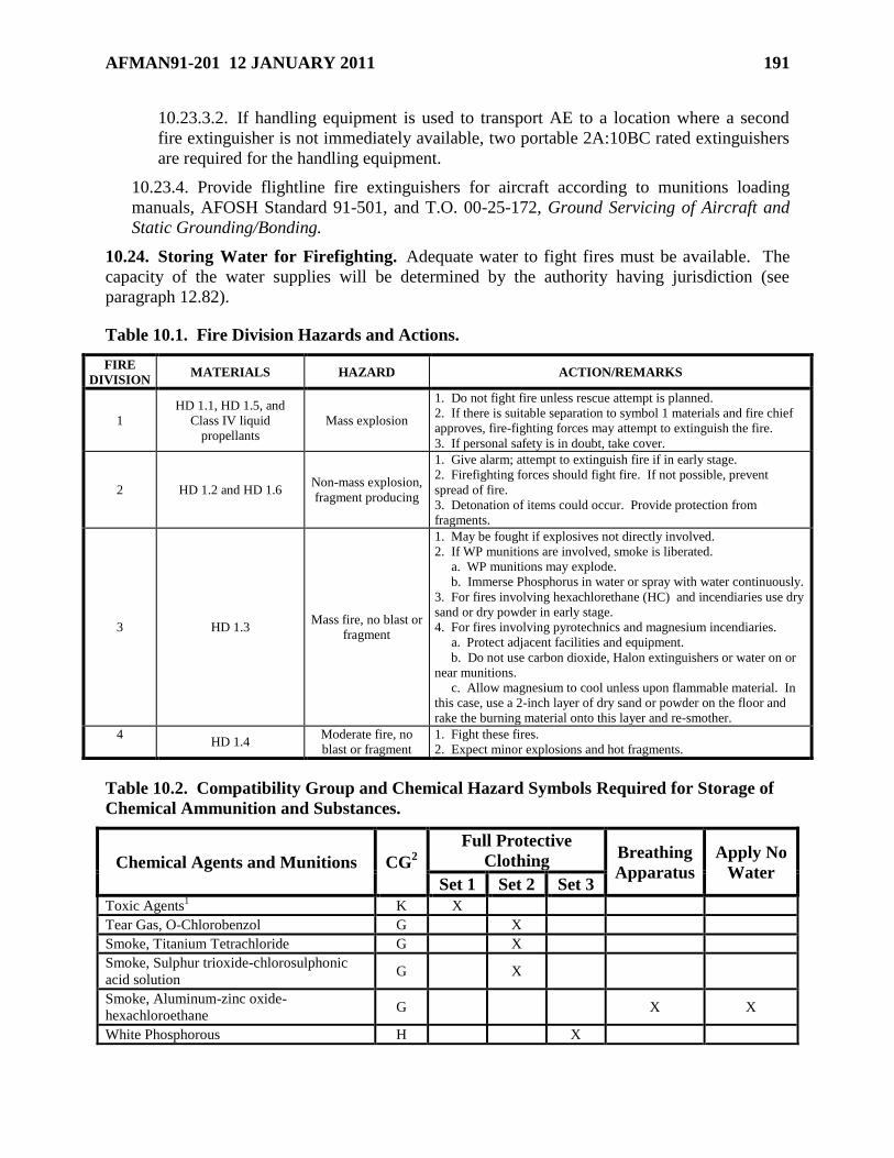
AFMAN91-201 12 JANUARY 2011 191
10.23.3.2. If handling equipment is used to transport AE to a location where a second
fire extinguisher is not immediately available, two portable 2A:10BC rated extinguishers
are required for the handling equipment.
10.23.4. Provide flightline fire extinguishers for aircraft according to munitions loading
manuals, AFOSH Standard 91-501, and T.O. 00-25-172, Ground Servicing of Aircraft and
Static Grounding/Bonding.
10.24. Storing Water for Firefighting. Adequate water to fight fires must be available. The
capacity of the water supplies will be determined by the authority having jurisdiction (see
paragraph 12.82).
Table 10.1. Fire Division Hazards and Actions.
FIRE
DIVISION MATERIALS HAZARD ACTION/REMARKS
1
HD 1.1, HD 1.5, and
Class IV liquid
propellants
Mass explosion
1. Do not fight fire unless rescue attempt is planned.
2. If there is suitable separation to symbol 1 materials and fire chief
approves, fire-fighting forces may attempt to extinguish the fire.
3. If personal safety is in doubt, take cover.
2 HD 1.2 and HD 1.6 Non-mass explosion,
fragment producing
1. Give alarm; attempt to extinguish fire if in early stage.
2. Firefighting forces should fight fire. If not possible, prevent
spread of fire.
3. Detonation of items could occur. Provide protection from
fragments.
3 HD 1.3 Mass fire, no blast or
fragment
1. May be fought if explosives not directly involved.
2. If WP munitions are involved, smoke is liberated.
a. WP munitions may explode.
b. Immerse Phosphorus in water or spray with water continuously.
3. For fires involving hexachlorethane (HC) and incendiaries use dry
sand or dry powder in early stage.
4. For fires involving pyrotechnics and magnesium incendiaries.
a. Protect adjacent facilities and equipment.
b. Do not use carbon dioxide, Halon extinguishers or water on or
near munitions.
c. Allow magnesium to cool unless upon flammable material. In
this case, use a 2-inch layer of dry sand or powder on the floor and
rake the burning material onto this layer and re-smother.
4
HD 1.4
Moderate fire, no
blast or fragment
1. Fight these fires.
2. Expect minor explosions and hot fragments.
Table 10.2. Compatibility Group and Chemical Hazard Symbols Required for Storage of
Chemical Ammunition and Substances.
Chemical Agents and Munitions CG2
Full Protective
Clothing Breathing
Apparatus
Apply No
Water Set 1 Set 2 Set 3
Toxic Agents1 K X
Tear Gas, O-Chlorobenzol G X
Smoke, Titanium Tetrachloride G X
Smoke, Sulphur trioxide-chlorosulphonic
acid solution G X
Smoke, Aluminum-zinc oxide-
hexachloroethane G X X
White Phosphorous H X
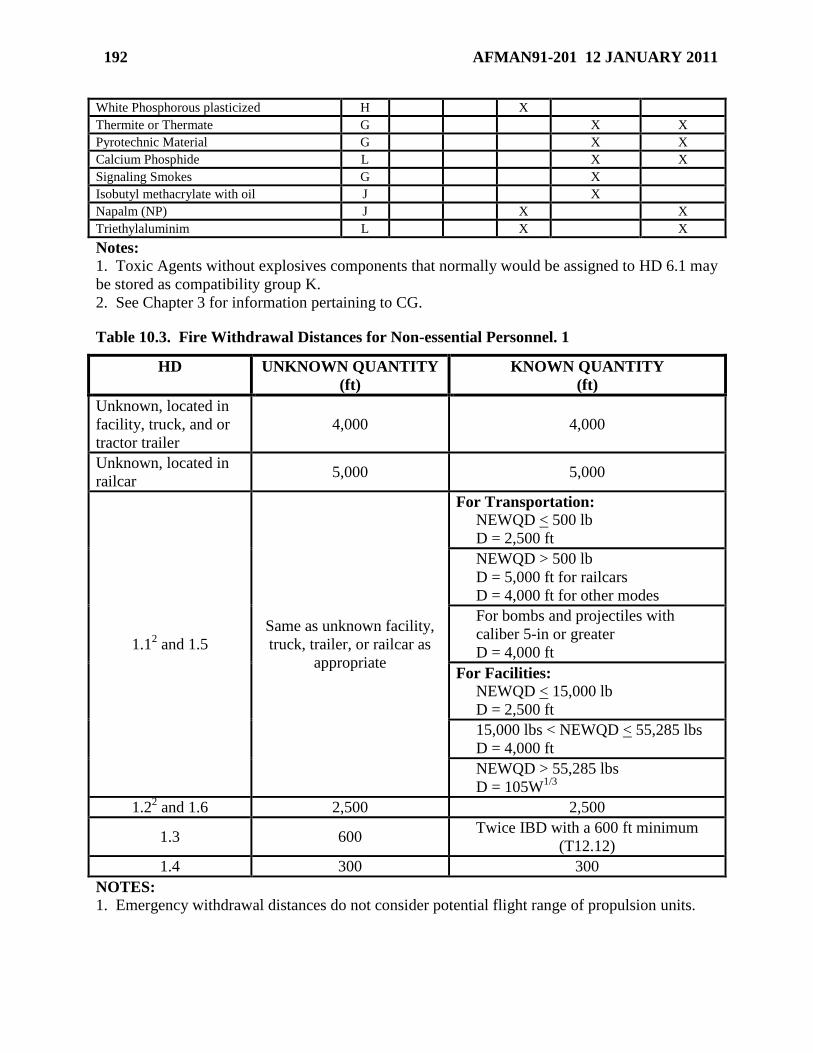
192 AFMAN91-201 12 JANUARY 2011
White Phosphorous plasticized H X
Thermite or Thermate G X X
Pyrotechnic Material G X X
Calcium Phosphide L X X
Signaling Smokes G X
Isobutyl methacrylate with oil J X
Napalm (NP) J X X
Triethylaluminim L X X
Notes:
1. Toxic Agents without explosives components that normally would be assigned to HD 6.1 may
be stored as compatibility group K.
2. See Chapter 3 for information pertaining to CG.
Table 10.3. Fire Withdrawal Distances for Non-essential Personnel. 1
HD UNKNOWN QUANTITY
(ft)
KNOWN QUANTITY
(ft)
Unknown, located in
facility, truck, and or
tractor trailer
4,000 4,000
Unknown, located in
railcar 5,000 5,000
1.12 and 1.5
Same as unknown facility,
truck, trailer, or railcar as
appropriate
For Transportation:
NEWQD < 500 lb
D = 2,500 ft
NEWQD > 500 lb
D = 5,000 ft for railcars
D = 4,000 ft for other modes
For bombs and projectiles with
caliber 5-in or greater
D = 4,000 ft
For Facilities:
NEWQD < 15,000 lb
D = 2,500 ft
15,000 lbs < NEWQD < 55,285 lbs
D = 4,000 ft
NEWQD > 55,285 lbs
D = 105W1/3
1.22 and 1.6 2,500 2,500
1.3 600 Twice IBD with a 600 ft minimum
(T12.12)
1.4 300 300
NOTES:
1. Emergency withdrawal distances do not consider potential flight range of propulsion units.

AFMAN91-201 12 JANUARY 2011 193
2. For HD 1.1 and HD 1.2 AE, if known, the maximum range fragments and debris will be
thrown (including the interaction effects of stacks of items, but excluding lugs, strongbacks, and
or nose and tail plates) may be used to replace the distances given.
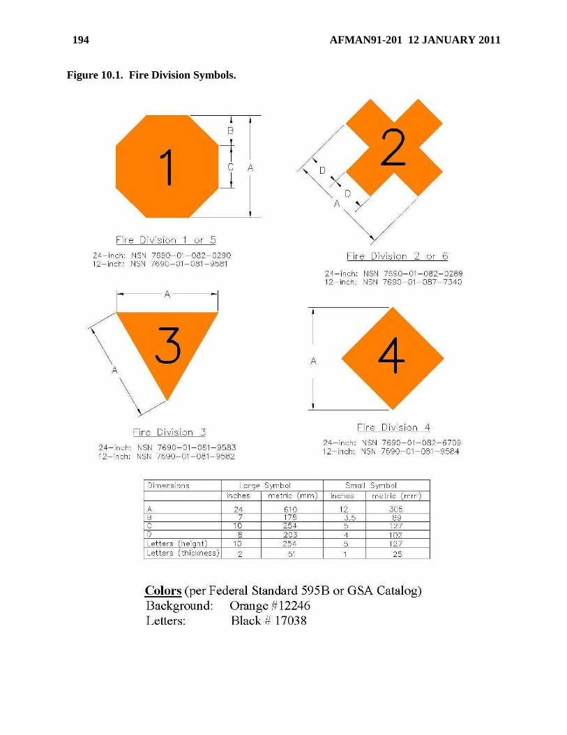
194 AFMAN91-201 12 JANUARY 2011
Figure 10.1. Fire Division Symbols.
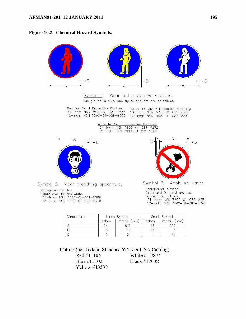
AFMAN91-201 12 JANUARY 2011 195
Figure 10.2. Chemical Hazard Symbols.
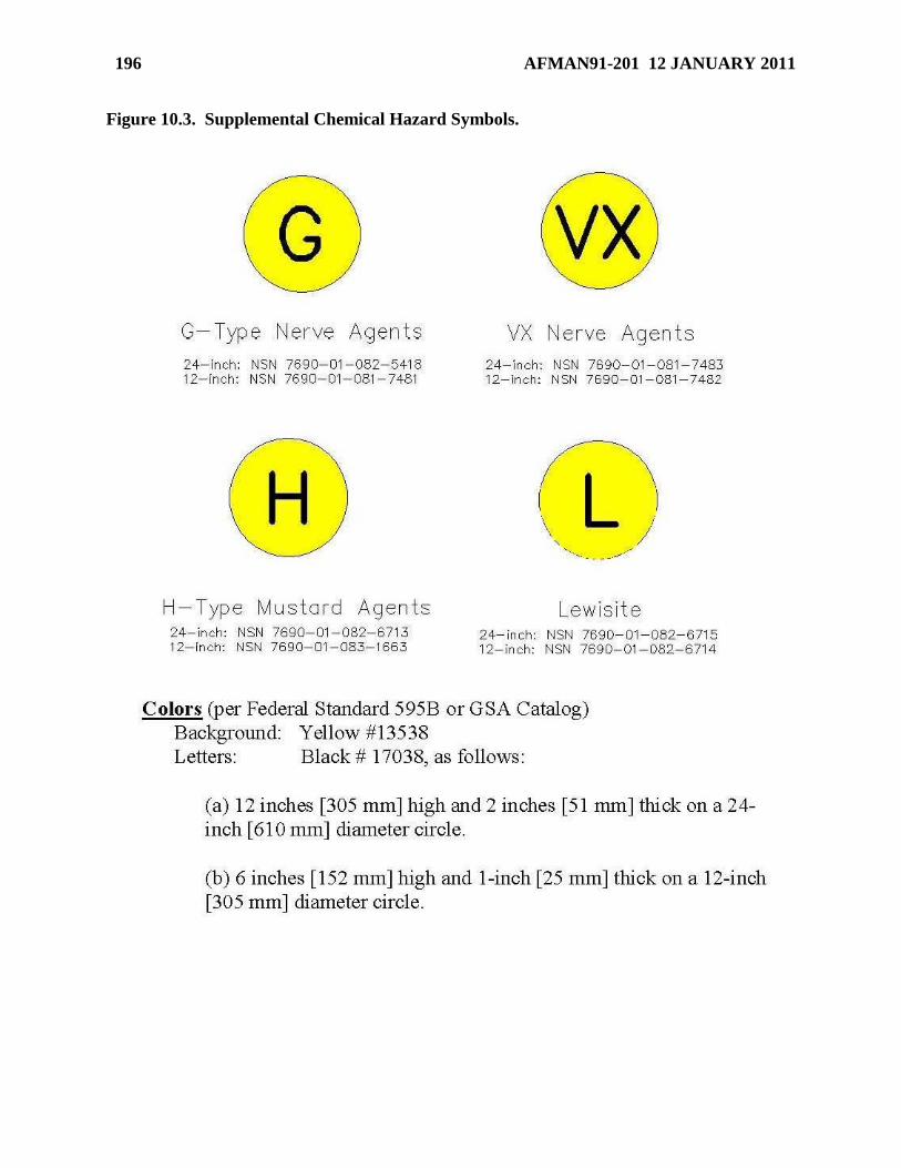
196 AFMAN91-201 12 JANUARY 2011
Figure 10.3. Supplemental Chemical Hazard Symbols.
AFMAN91-201 12 JANUARY 2011 197
Chapter 11
LICENSED EXPLOSIVES STORAGE LOCATIONS
Section 11A—Purpose and Limitations for Licensed Explosives Storage Locations
11.1. Purpose of Licensed Explosives Storage Locations. Storage of small amounts of AE is
sometimes required in facilities or locations that are not explosives sited in accordance with
Chapter 14. Such storage may be permitted in a licensed explosives storage location in
accordance with the requirements of this chapter. Operations involving AE stored in explosives
licensed locations and storage of AE not requiring licensing or explosives siting are also covered
in this chapter.
11.1.1. Licenses do not apply to explosives operations other than those listed in this chapter.
11.1.2. Licenses are not to be used for convenience.
11.1.3. Licenses are issued by the host weapons safety office.
11.1.4. Except as specified in this chapter, QD requirements do not apply to licensed
explosives storage locations.
11.1.5. Local written instructions are required for each explosives license.
11.2. General Limitations on AE in Licensed Explosives Storage Locations.
11.2.1. Quantities of AE must be limited to minimum quantities necessary to support
specific, mission essential, and explosives operations or missions.
11.2.2. CG A, K, and L will not be licensed. Compatibility requirements specified
elsewhere in this Manual do not apply.
11.2.3. HD 1.2.1 and HD 1.2.3 will not be stored in a licensed explosives location, except as
allowed per paragraph 11.15.
11.2.4. HD 1.1 will not be stored in a licensed explosives location, except as allowed per
paragraphs 11.15 and 11.23.
11.3. NEWQD Limitations on AE in Licensed Explosives Storage Locations. The following
quantities of AE, expressed as NEWQD, will not be exceeded on any one license.
11.3.1. Mission essential quantities of HD 1.4.
11.3.2. 100 lbs of HD 1.3.
11.3.3. 100 lbs of HD 1.2.2.
11.3.4. Deleted.
11.3.5. Turn in unserviceable explosive components or items to the base munitions storage
area as quickly as possible to preclude build-up of unserviceable NEWQD. Unserviceable
NEWQD must be counted against the total NEWQD of the licensed facility.
Section 11B—Requirements for Licensed Explosives Storage Locations
198 AFMAN91-201 12 JANUARY 2011
11.4. General Requirements for Licensed Explosives Storage Locations.
11.4.1. The structure or room used for storage must be capable of being locked to prevent
pilferage and unauthorized handling. Contact Security Forces for resource protection
requirements.
11.4.2. Post firefighting symbols in accordance with paragraph 10.7.
11.4.3. Provide dunnage for ventilation when required by civil engineering, logistics or
bioenvironmental directives.
11.5. Separation Requirements for Licensed Explosives Storage Locations.
11.5.1. No separation requirements apply to HD 1.4 AE stored in licensed explosives storage
locations.
11.5.2. A minimum separation of 25 ft is required from licensed explosives storage locations
containing HD 1.3 AE to unrelated explosives operations, unrelated personnel, or other
licensed explosives storage locations. Where 25 ft cannot be obtained, a 2-hour fire rated
wall or 2-hour fire rated cabinet is required.
11.5.3. A minimum separation of 100 ft is required from licensed explosives storage
locations containing HD 1.2.2 AE to unrelated explosives operations, unrelated personnel, or
other licensed explosives storage locations. Where 100 ft cannot be maintained, a fragment
barrier that provides protection equal to ¼-inch mild steel plate or one layer of sand bags is
required. A substantial dividing wall (SDW) (see paragraph 6.28) is an acceptable fragment
barrier.
11.5.4. A fragment barrier consisting of either a ¼-inch mild steel plate or one layer of sand
bags is required when HD 1.2.2 is stored inside or IBD is not provided to other non-related
facilities.
11.5.5. In accordance with the general explosives safety requirement to separate explosives
storage and operations, the maximum separation possible shall be provided between a
licensed explosives storage location and the operation and personnel it supports. The
requirements of paragraphs 11.5.2 and 11.5.3 shall be complied with to the maximum extent
possible.
11.5.6. Parking Areas.
11.5.6.1. POV, GOV and AGE parking areas will be located a minimum of 100 ft from a
licensed location. This minimum distance of 100 ft may be reduced to 50 ft if the PES is
of non-combustible construction, a barrier sufficient to prevent the vehicle from rolling
within 50 ft of the PES is located between the POV parking spaces and the PES.
11.5.6.2. Temporary parking of GOVs or AGE, other than those being loaded or
unloaded, will not be closer than 25 ft to any licensed location. Temporary means the
length of time for which the presence of the vehicle is essential to completion of a single
task (e.g., a single work order number).
11.5.6.3. Local fire and safety officials may reduce these parking requirements for each
licensed location.
Section 11C—Documentation for Licensed Explosives Storage Locations
AFMAN91-201 12 JANUARY 2011 199
11.6. AF Form 2047. Use AF Form 2047, Explosive Facility License, to document approval for
licensed explosives storage locations. This form is shown in Figure 11.1. The AF Form 2047
must be displayed at the licensed explosives storage location.
11.7. Instructions for Completing AF Form 2047.
11.7.1. Item 1. Enter name of base.
11.7.2. Item 2. Enter name of requesting organization.
11.7.3. Item 3. Enter license number. The installation weapons safety manager will assign
a number that will consist of the last two digits of the calendar year and a serial number,
assigned in numerical sequence. (For example, the first license issued in 2003 would be
numbered 03-1, the second would be 03-2.)
11.7.4. Section I:
11.7.4.1. Item 4. Enter building number as shown on TAB C-1 of the base
comprehensive plan. For an unnumbered facility, insert narrative description such as
outdoor storage (in-transit).
11.7.4.2. Item 5. Enter description of the primary use of the facility (e.g., alert hangar,
small arms range, egress shop, security and administrative building, rod and gun club, life
support shop).
11.7.4.3. Item 6. Enter identifying number of applicable written operating instructions.
11.7.4.4. Item 7. If applicable, enter room number of the facility where explosives will
be stored.
11.7.4.5. Item 8. If applicable, describe the room’s purpose.
11.7.4.6. Item 9. Enter brief description of facility construction (e.g., concrete-masonry,
wood frame).
11.7.5. . Enter the following information for each AE item (Section II is continued on the
back side of the form if more room is required):
11.7.5.1. Column A. HD.
11.7.5.2. Column B. CG.
11.7.5.3. Column C. Enter stocklist nomenclature and national stock number (NSN), or
federal supply class and Department of Defense Identification Code (DODIC).
11.7.5.4. Column D. Enter number of items authorized (both serviceable and
unserviceable).
11.7.5.5. Column E. Enter total NEWQD based on number of items authorized. This
column does not apply to HD 1.4 items.
11.7.5.6. Column F. Enter appropriate firefighting and chemical symbols.
11.7.6. . The commander of organization or the functional manager requesting the license
will be the certifying official.
11.7.7. . The individual who is assigned installation weapons safety responsibilities signs as
the responsible official after:

200 AFMAN91-201 12 JANUARY 2011
11.7.7.1. Validating the quantity of AE to be kept.
11.7.7.2. Ensuring only the smallest quantity of AE needed to support mission
requirements is authorized.
11.7.7.3. Physically inspecting the facility to ensure firefighting symbols are available
for posting in accordance with paragraph 10.7.
11.7.7.4. Ensuring copies of applicable T.O. or other procedures are available at the
facility.
11.7.7.5. Obtaining the coordination required in Section V.
11.7.7.6. Ensuring the installation Fire Protection Agency has completed the remarks
section per paragraph 11.7.8.1.
11.7.8. Remarks.
11.7.8.1. The installation Fire Protection Agency will enter the specific type, quantity,
and physical placement of fire extinguishers for the location, as well as any additional
fire prevention practices.
11.7.8.2. If applicable, enter conditions of approval, expiration date (if other than
indefinite), reasons pertaining to disapproval, comments of requesting organization, and
T.O. or other procedural references.
11.7.9. . Enter office symbols, dates, and names of coordinators.
11.7.9.1. Coordinate through responsible Munitions Accountable System Officer, the
local Security Forces Resource Protection office and the installation Fire Protection
Agency prior to being approved by the installation Weapons Safety Office.
11.7.9.2. Prior to coordination, the Security Forces Resource Protection office must
physically inspect the facility to ensure the requirements of paragraph 11.4.1 have been
met.
11.7.9.3. For licenses involving privately-owned ammunition outside the United States
and Guam, obtain the installation’s judge advocate coordination to ensure no host nation
laws are being violated.
11.8. Maintaining the AF Form 2047.
11.8.1. Update the AF Form 2047 each time the HD, NEWQD, CG, or quantity of AE items
changes.
11.8.2. When Munitions Operations (AFK) issues suitable substitutions for stock listed
items, updating the AF Form 2047 is not required as long as the HD, NEWQD, CG, and
quantity of AE items does not change. Place an asterisk (*) next to the stock number listed in
column ―C‖ of the AF Form 2047 that is posted at the location and enter in the ―Remarks‖
block, ―*Suitable substitute issued.‖
11.8.3. Review the AF Form 2047 annually for continued requirement and applicability.
11.8.4. Cancel the AF Form 2047 when the requirement no longer exists.
Section 11D—Operations Involving AE Stored in Licensed Explosives Storage Locations
AFMAN91-201 12 JANUARY 2011 201
11.9. Operations Involving AE Stored Licensed Explosives Storage Locations.
11.9.1. The unit or squadron commander (or equivalent) approves locally-written
instructions (see Section 7B) as the authorization for operations involving AE stored in a
licensed explosives storage location. These instructions must be available for the operation.
11.9.2. An ESP is not required for these operations as a PES.
11.9.3. These operations must be sited as an ES if located within the IBD of a PES.
11.9.4. Separation distances for these operations must meet the minimum distances specified
in paragraph 11.5.
Section 11E—Requirements for Specific Licensed Explosives Storage Locations
11.10. Mobility Storage. AE designated for mobility shall be stored within the base munitions
storage area until ready for shipment, unless the deploying unit has an extremely short timeline
requirement that makes it impossible to store within the MSA. License the storage of pre-
positioned mobility AE only if a properly sited area is not available. The license is valid only for
the duration of the mobility tasking. At host units without a designated munitions storage area,
explosive items designated for mobility may be stored in a consolidated licensed location
providing adherence to all Chapter 11 provisions.
11.11. Training and Exercises. Licensing AE locations used solely for exercises, such as the
ground burst simulators, smoke grenade storage, etc., is permitted. This license is valid only for
the duration of the exercise.
11.12. Control Tower. If required, license the storage of necessary quantities of HD 1.3
pyrotechnics needed to conduct emergency operations at fixed and mobile control towers. Do
not load pyrotechnic projectors and pistols unless the operational situation demands a state of
immediate readiness. The same safety and security requirements that apply to firearms apply to
projectors and pistols. Place in a proper rack, locker, box or compartment to prevent damage,
unauthorized handling, theft or accidental discharge.
11.13. Aircrew Flight Equipment.
11.13.1. A license is not required for assembled parachutes, aircrew flight equipment kits,
life rafts and life preservers containing authorized explosives when kept in personnel
equipment rooms, life rafts, and aircrew flight equipment shops.
11.13.2. A license is required for those areas in which aircrew flight equipment explosive
components are stored.
11.13.3. An operating instruction, approved by the commander (see Section 7B), is required
for all aircrew flight equipment shop operations involving explosive components.
11.14. Riot Control Items. If required, store riot control and smoke grenades (except WP
grenades) with small arms ammunition in arms rooms and other such locations. However, if the
arms room is collocated with a facility where personnel are under physical restraint or
confinement, the National Fire Codes, Standard 101, Life Safety Code, applies. Don't store 40-
millimeter grenades, pyrotechnics, tear gas or chemical irritants in the room regardless of the QD
division or compatibility, unless the arms room has protective features which completely protect
detainees from the effects of accidental explosives activation. Protective features include
202 AFMAN91-201 12 JANUARY 2011
fragment barriers, blast doors, and exhaust fans. Qualified engineers must evaluate capabilities
of protective features. Limit the quantity to the smallest amount needed to support approved
contingency plans.
11.15. Egress Systems Maintenance Shops. When necessary, units may license a limited
quantity of in-use egress explosive components of any hazard division (including HD 1.1) in the
egress shop after removal from aircraft undergoing maintenance. Don't exceed the total number
of complete sets for the number of aircraft in maintenance. The following special provisions
apply:
11.15.1. Ejection seats, canopies, and explosives components not undergoing actual
maintenance, will be stored in a separate location outside the maintenance area. Ejection
seats may only be stored in the maintenance area while maintenance is being conducted on
other seats if all explosive components have been removed from the seats to be stored and
placed in a separate storage location.
11.15.2. Within the egress maintenance work area, the NEWQD limitations in paragraph
11.3 apply to the number of seats and spare components undergoing maintenance at any one
time.
11.16. Gun Systems and Maintenance Shops. When possible, remove ammunition from guns
and gun systems before they are brought into a weapons maintenance facility for repair. Gun
systems using drums don’t require removal of ammunition if the feed system is mechanically
safed to prevent ammunition from feeding into the gun. QD requirements do not apply to gun
system maintenance operations when explosives are limited to HD 1.4 and 100 pounds of HD
1.2.2 provided the using organizations ensure:
11.16.1. MAJCOMs will establish procedures for clearing jammed guns. Consider both
active and contingency bases.
11.16.2. Guns or gun systems loaded with ammunition will not be brought into the
maintenance facility until needed to meet the work schedule and are removed immediately
after repair.
11.16.3. Precautions are established to prevent inadvertent firing.
11.16.4. Gun systems with live ammunition are grounded.
11.16.5. Gun system is pointed in the least hazardous direction.
11.16.6. Downloaded ammunition is removed from the building and returned to the base
munitions storage area as soon as possible.
11.16.7. Compliance with general explosives safety standards.
11.17. Incendiary Equipment and Document Destroyers. If necessary, store these items near
the planned point of use to comply with emergency destruction plans. Establish quantities for
each location by coordinating with base explosives safety representatives and your security
representatives. The 100-pound HD 1.3 limit does not apply in this case. Limit quantity to the
amount needed for emergency destruction plans. Training quantities are not authorized.
Construct or protect storage rooms with noncombustible or fire-resistive material. If possible
store in nearby small low-cost structures (sheds, conex, etc.). Ensure adequate ventilation is
provided. Maintain 50-foot firebreaks or vegetation control zones and locate at least 75 feet
AFMAN91-201 12 JANUARY 2011 203
from any other building. Store replacement stocks in the base explosives storage area. Only
trained personnel are allowed to prepare and activate these devices.
11.18. Rod and Gun Clubs. License the explosives storage locations for clubs that hand-load
ammunition on Air Force property. For skeet and trap ranges adhere to criteria established by
the National Skeet Shooting Association. See also paragraphs 11.19 and 11.20. Designate a
qualified member to identify and enforce criteria.
11.19. Retail Stores. Where only retail sales are made, paragraph 11.25 applies. Don't
complete a license unless the store sells primers and smokeless powder. More than 100 lbs of
propellant and 25,000 primers, packed in their shipping containers, may be licensed if they are
segregated in such a way that the MCE does not exceed 100 lbs of propellant and 25,000
primers, i.e., if IM separation is met. Don't place HD 1.3 propellant in other containers if it
would result in extreme confinement in the event of ignition. Use fire symbol 3 to designate the
presence of both the propellant and primers. Keep the symbol posted during temporary periods
when the propellant has been sold out, but primers are still in stock.
11.20. Hand Loading. Conduct hand-loading operations in a room or building used solely for
this purpose. Don't store or reload ammunition in dormitories or bachelor officer quarters. Use
retail store safety requirements as well as the following:
11.20.1. Develop and post an approved, locally-written procedure. Refer to AFI 31-101,
Integrated Defense, for security.
11.20.2. Grant loading privileges to only authorized personnel trained in the use of hand-
loading equipment, safety provisions, and hazards involved. Wear safety goggles or face
shields during all loading operations.
11.20.3. Strictly supervise members in training. Keep a log showing names of certifying
instructors and each person who has satisfactorily completed the training.
11.20.4. Do not permit smoking, matches or flame-producing devices in any loading or
storage location.
11.20.5. Place a ground bar with a resistance of 25 Ohms or less at each entrance to the
hand-loading room.
11.20.6. Post a sign requiring each person to touch the ground bar before entering the room.
11.20.7. Maintain and inspect the ground bar as outlined in Chapter 5.
11.20.8. Post explosives and personnel limits. Allow no more than 10 lbs of propellants,
10,000 primers, and 5,000 assembled rounds in the hand loading room at one time. These
quantities are considered as part of the overall limits for the building.
11.20.9. Provide storage lockers for propellant and transfer to the loading point only
quantities required to sustain a continuous operation.
11.20.10. Remove only one packing tray at a time from primer storage.
11.20.11. Repack unused components in their original containers and return them to the
storage locker at the end of each loading operation.
11.20.12. Lock unused lockers.

204 AFMAN91-201 12 JANUARY 2011
11.20.13. Cover tables used for hand loading with a seamless, nonporous, non-sparking
conductive material.
11.20.14. Permanently attach and bond hand-loading equipment to a 25 Ohm or less
grounded tabletop.
11.20.15. Test the grounding system twice a year and when broken connectors are repaired.
11.20.16. Document grounding system test results.
11.20.17. Visually inspect ground conductors before each day's operation.
11.20.18. Keep floors and walls free of cracks that could accumulate explosive dust and
foreign materials. Observe good housekeeping practices at all times.
11.20.19. In case of a spill, stop all operations until the propellant is cleaned up.
11.20.20. Put all salvaged propellant in a metal container that contains water and is marked
"Scrap Explosives."
11.20.21. Put all damaged components or complete rounds in separate, properly-marked
containers.
11.20.22. Separate unserviceable items from serviceable stocks.
11.20.23. Qualified personnel must dispose of unserviceable propellants, damaged rounds or
components, and empty explosives containers as directed in T.O. 11A-1-42, General
Instructions for Disposal of Conventional Munitions, and T.O. 11A-1-60, Inspection of
Reusable Munitions Containers and Scrap Material.
11.20.24. Use only commercial-type loading tools, dies, scales, powder measures, and so
forth for hand-loading operations.
11.20.25. Place personnel protection shields between each piece of permanently-attached
hand-loading equipment. Shields must be large enough to protect adjacent personnel.
Shields can be made of plywood, Plexiglas or similar materials.
11.20.26. Do bullet molding outside the hand-loading room.
11.21. Force Support Squadron Activities (formerly MWR Activities). Force Support
Squadron activities such as aero clubs and boating activities are sometimes required to maintain
and store commercial pyrotechnic signals. Control and store these items using the same criteria
as the military item which they resemble. Ensure personnel are properly trained. License the
storage locations. Technical data or manufacturer's data are sources for locally-written
procedures.
11.22. Minuteman Handling Team Facility. The transporter erector (TE) tractor or autocar
with missile in tow may require temporary storage in the Minuteman Handling Team (MHT)
facility. When using this procedure, comply with the following conditions:
11.22.1. Storage is essential to meet operating requirements.
11.22.2. Vehicle is chocked and grounded.
11.22.3. Vehicle safety inspection is performed and no safety deficiencies exist.
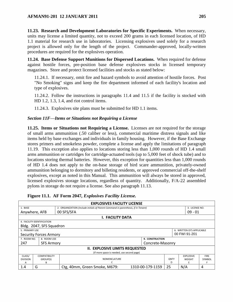
AFMAN91-201 12 JANUARY 2011 205
11.23. Research and Development Laboratories for Specific Experiments. When necessary,
units may license a limited quantity, not to exceed 200 grams in each licensed location, of HD
1.1 material for research use in laboratories. Licensing explosives used solely for a research
project is allowed only for the length of the project. Commander-approved, locally-written
procedures are required for the explosives operation.
11.24. Base Defense Support Munitions for Dispersed Locations. When required for defense
against hostile forces, pre-position base defense explosives stocks in licensed temporary
magazines. Store and protect licensed facilities and stocks as stated below:
11.24.1. If necessary, omit fire and hazard symbols to avoid attention of hostile forces. Post
"No Smoking" signs and keep the fire department informed of each facility's location and
type of explosives.
11.24.2. Follow the instructions in paragraphs 11.4 and 11.5 if the facility is stocked with
HD 1.2, 1.3, 1.4, and riot control items.
11.24.3. Explosives site plans must be submitted for HD 1.1 items.
Section 11F—Items or Situations not Requiring a License
11.25. Items or Situations not Requiring a License. Licenses are not required for the storage
of small arms ammunition (.50 caliber or less), commercial maritime distress signals and like
items held by base exchanges and individuals in family housing. However, if the Base Exchange
stores primers and smokeless powder, complete a license and apply the limitations of paragraph
11.19. This exception also applies to locations storing less than 1,000 rounds of HD 1.4 small
arms ammunition or cartridges for cartridge-actuated tools (up to 5,000 feet of shock tube) and to
locations storing thermal batteries. However, this exception for quantities less than 1,000 rounds
of HD 1.4 does not apply to the on-base storage of bird scare ammunition, privately-owned
ammunition belonging to dormitory and billeting residents, or approved commercial off-the-shelf
explosives, except as noted in this Manual. This ammunition will always be stored in approved,
licensed explosives storage locations, regardless of quantity. Additionally, F/A-22 assembled
pylons in storage do not require a license. See also paragraph 11.13.
Figure 11.1. AF Form 2047, Explosives Facility License.
EXPLOSIVES FACILITY LICENSE 1. BASE
Anywhere, AFB 2. ORGANIZATION (Include initials of Parent Command in parenthesis, if in Tenant)
00 SFS/SFA
3. LICENSE NO.
09 - 01
I. FACILITY DATA 4. FACILITY IDENTIFICATION
Bldg. 2047, SFS Squadron 5. PRIMARY USE
Security Forces Armory 6. WRITTEN OI’S APPLICABLE
00 FWI 91-201
7. ROOM NO.
247 8. ROOM USE
SFS Armory 9. CONSTRUCTION
Concrete-Masonry
II. EXPLOSIVE LIMITS REQUESTED (If more space is needed, use second page)
CLASS/ DIVISION
A
COMPATIBILITY GROUP(S)
B
NOMENCLATURE C
QNTY D
EXPLOSIVE WEIGHT
E
FIRE SYMBOL
F
1.4 G Ctg, 40mm, Green Smoke, M679: 1310-00-179-1159 25 N/A 4
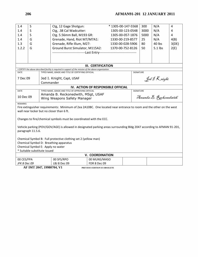
206 AFMAN91-201 12 JANUARY 2011
1.4 1.4 1.4 1.4 1.3 1.2.2
S S S G G G
Ctg, 12 Gage Shotgun: * 1305-00-147-5568 Ctg, .38 Cal Wadcutter: 1305-00-123-0548 Ctg. 5.56mm Ball, M193 GR: 1305-00-057-1876 Grenade, Hand, Riot M7/M7A1: 1330-00-219-8577 Grenade, Rifle Illum, M27: 1330-00-028-5906 Ground Burst Simulator, M115A2: 1370-00-752-8126 ------------------------------Last Entry----------------------------------
300 3000 5000 25 80 50
N/A N/A N/A N/A 40 lbs 5.1 lbs
4 4 4 4(B) 3(DE) 2(E)
III. CERTIFICATION I CERTIFY the above described facility is required in support of the mission of the above organization.
DATE
7 Dec 09
TYPED NAME, GRADE AND TITLE OF CERTIFYING OFFICIAL
Jed I. Knight, Capt, USAF Commander
SIGNATURE
Jed I. Knight
IV. ACTION OF RESPONSIBLE OFFICIAL DATE
10 Dec 09
TYPED NAME, GRADE AND TITLE OF APPROVING OFFICIAL
Amanda B. Reckonedwith, MSgt, USAF
Wing Weapons Safety Manager
SIGNATURE
Amanda B. Reckonedwith REMARKS
Fire extinguisher requirements: Minimum of 2ea 2A10BC. One located near entrance to room and the other on the west wall near locker but no closer than 6 ft. Changes to fire/chemical symbols must be coordinated with the ECC. Vehicle parking (POV/GOV/AGE) is allowed in designated parking areas surrounding Bldg 2047 according to AFMAN 91-201, paragraph 11.5.6. Chemical Symbol B: Full protective clothing set 2 (yellow man) Chemical Symbol D: Breathing apparatus Chemical Symbol E: Apply no water * Suitable substitute issued
V. COORDINATION 00 CES/FPA JFK 8 Dec 09
00 SFS/RPO LBJ 8 Dec 09
00 MUNS/MASO FDR 8 Dec 09
AF IMT 2047, 19980704, V1 PREVIOUS EDITION IS OBSOLETE
AFMAN91-201 12 JANUARY 2011 207
Chapter 12
QUANTITY-DISTANCE CRITERIA
Section 12A—Introduction
12.1. Introduction. The term ―Quantity-Distance‖ (QD) refers to protection requirements from
potential explosion sites (PES) to different kinds of exposed sites (ES). The QD standards were
developed over many years and are based on explosives mishaps, tests and analyses. QD
separations are based on an acceptable level of damage between a PES and an ES.
12.1.1. The damage or injury potential of explosions is normally determined by the
separation distance between the PES and ES; the ability of the PES to suppress blast
overpressure, primary and secondary fragments; and the ability of the ES to resist explosion
effects. This chapter:
12.1.1.1. Defines permissible exposures for both accidental and intentional detonations.
12.1.1.2. Sets minimum standards for separation distances between PES and ES by
taking into account anticipated explosion effects, suppression, and resistance.
12.1.1.3. Establishes explosives safety siting criteria (QD relationships) for PES and ES,
based on blast, fragment, firebrand, thermal, and groundshock effects. QD is determined
by the effect requiring the greatest distance.
12.1.2. When an appropriate degree of protection can be provided either by hardening an ES
or construction of a PES to suppress explosion effects, these factors may be taken into
account and the distance required by the standard QD tables may be reduced. Submit
construction designs with rationale or test results with the explosives site plan (ESP). See
Chapter 6.
12.1.3. QD separation does not apply to AE in the transportation mode (reference Chapter
8).
Section 12B—Quantity-Distance Principles
12.2. General. The bases for determining required separation distances (QD) are:
12.2.1. The construction and type of PES.
12.2.2. The HD types and NEWQD of AE present in the PES.
12.2.3. The construction and type of ES.
12.2.4. The distance separating the PES from the ES.
12.2.5. In some instances, the orientation of the PES and the ES.
12.3. Types of Separations.
12.3.1. Inhabited Building Distance (IBD). This is the minimum distance required to
protect facilities and personnel not directly related to explosives storage and operations. At
208 AFMAN91-201 12 JANUARY 2011
this distance, some damage and personnel injury may still be expected (see Chapter 2 for
reaction effects).
12.3.2. Public Traffic Route Distance (PTRD). This is the minimum distance required to
protect public traffic routes (see paragraph 12.16.3 for on-base roads) and other designated
exposures. At this distance, damage and personnel injury is expected (see Chapter 2 for
reaction effects). For HD 1.1 and 1.2, PTRD is normally 60% of IBD. For HD 1.3 and 1.4,
PTRD is the same as IBD. Public traffic routes are classified as high, medium, and low
traffic density. The traffic density will be averaged over a normal (non-holiday) week in
terms of number of passengers during a 24-hour period. (Note: In applying criteria other
than the default values given below (which are based on car (and rail) speed of 50 mph, and a
ship speed of 10 mph), considerations such as the following will be taken into account to
establish exposure levels: speed of vehicles, number of passengers per vehicle, protection
afforded by the vehicle, variation in daily traffic levels in relation to AE activities, and
seasonal traffic trends. The default value of two passengers per car may be used to estimate
traffic density.)
12.3.2.1. High Traffic Density. Routes which have 10,000 or more car or rail
passengers per day, or 2,000 or more ship passengers per day. IBD separation is required
for high traffic density routes per paragraph 12.15.1.19.
12.3.2.2. Medium Traffic Density. Routes which have at least 400 but less than 10,000
car or rail passengers per day, or at least 80 but less than 2,000 ship passengers per day.
As a minimum, medium traffic density route criteria apply to any recreational activity
that is extensive and occurs on a regular basis. PTRD separation is required for medium
traffic density routes per paragraph 12.16.1.
12.3.2.3. Low Traffic Density. Routes which have fewer than 400 car or rail passengers
per day, or fewer than 80 ship passengers per day. PTRD separation (based on blast
criteria only) is required for low traffic density routes per paragraph 12.16.2.
12.3.3. Intraline Distance (ILD). This is the minimum distance required to protect
activities associated with explosives storage and operations. Applying ILD recognizes the
operational need for some people to be in the proximity of explosives while at the same time
preserving some mission capability in the event of an explosives accident. Unhardened
facilities at this distance will be extensively damaged and occupants may be severely injured
(see Chapter 2 for reaction effects). In addition to the minimal protection to related
activities, ILD should prevent propagation between two explosives locations. At ILD, no
propagation from the blast overpressure is expected, and the probability of propagation from
low angle, high velocity fragments is significantly reduced. For HD 1.1 and 1.2, ILD is
normally 36% of IBD.
12.3.4. Intermagazine Distance (IMD). This is the minimum distance between PESs to
prevent one PES from simultaneously detonating an adjacent PES. Maintaining IMD is no
guarantee that propagation from one PES to another will not occur, only that they will not
simultaneously detonate. At this distance, severe structural damage approaching total
destruction is expected for conventional structures, and severe personnel injury or death is
expected (see Chapter 2 for reaction effects). Earth Covered Magazines (ECM) provide
significant protection at IMD; maintaining IMD between ECMs will provide virtually
complete protection of AE against the propagation effects of an explosion. However, AE in
AFMAN91-201 12 JANUARY 2011 209
adjacent ECMs may be damaged (see paragraph 2.1.5.3). When less than required IMD
exists between any two or more PESs, the quantities of explosives in these locations must be
added to form a single PES encompassing the area and NEWQDs of the PESs which do not
meet IMD. For this reason, any separation between explosives locations less than IMD may
not be waived.
Section 12C—Determining Net Explosive Weight for Quantity-Distance
12.4. Determining NEWQD of AE Items. See paragraph 3.6 for guidance on determining the
NEWQD of AE items. The explosive weight of Not-Regulated AE and AE assigned to Classes 2
through 9 is not considered for QD purposes (see paragraph 3.5).
12.5. Determining NEWQD of a PES. Generally, the combined NEWQD of all AE in a PES
is used as the NEWQD of the PES for explosives siting. Determine NEWQD of a PES as
follows:
12.5.1. If only one HD is present, combine the NEWQD of each AE item involved.
12.5.2. If multiple HDs are authorized, but only one HD is present at a time, determine the
NEWQD separately for each HD (as described in paragraph 12.5.1).
12.5.3. If more than one HD is present at the same time, determine the NEWQD per
paragraph 12.7.
12.5.4. See Section 12N for determining NEWQD for energetic liquids.
12.5.5. Where explosives are located in a common facility or location and are further
subdivided into cells or stacks by IMD or equivalent protection (such as for buffered storage
or multicubicals), the cell or stack with the greatest NEWQD may be used for explosives
siting if specifically allowed by this Manual or approved by AFSC/SEW. Where IMD or
equivalent protection is not provided, use the total NEWQD of all explosives.
12.5.6. For HD 1.2.1, the MCE as outlined in paragraph 3.16.4. will also be used as the basis
for determining applicable QD.
12.5.7. For HD 1.2.3, the LSRN as outlined in paragraph 14.23.6. will also be used as the
basis for determining applicable QD.
12.5.8. The NEWQD of a host nation PES that may be hazarding Air Force facilities and
personnel will be based on the maximum NEWQD the host nation indicates will ever be
present at that PES location. If the NEWQD cannot be obtained from the host nation, the
responsible safety staff must estimate the type and quantity of explosives. Base estimates on
knowledge of the host nation's military mission and type of facility involved (such as ECM,
aircraft shelter, or maintenance facility). As a general rule, use the maximum NEWQD that
would be allowed in a similar Air Force facility per paragraph 12.6.
12.5.9. When an AE conveyance (e.g., railroad car or motor vehicle), containing AE is not
separated from a PES in such a manner as to prevent mass detonation, then the conveyance
and PES will be considered as a unit and their NEWQD will be summed. This does not
apply to temporary staging for the purpose of loading/unloading.
12.5.10. The NEWQD of the HD requiring the greatest separation establishes the QD for the
facility when it is used for multiple operations.
210 AFMAN91-201 12 JANUARY 2011
12.6. Maximum NEWQD. Regardless of actual separations, maximum NEWQD limitations
for HD 1.1 and 1.2 are as follows:
12.6.1. ECMs (except as noted in paragraph 12.6.2) and AGMs: 500,000 lbs.
12.6.2. 7-Bar Navy Box Type: 500,000 lbs except as noted in DDESB TP 15.
12.6.3. Non-standard ECMs: 250,000 lbs. Note: Sitings of non-standard ECMs sited prior
to February 1999 for explosives weights not exceeding 250,000 lbs remain valid. Future
sitings, including those where these ECMs are exposed sites, must comply with this Manual.
12.6.4. Barricaded modules at K1.1: 250,000 lbs.
12.6.5. Hardened Aircraft Shelters (HASs): See para 12.51.5.
12.6.6. Some facilities may have additional limits in order to use reduced QD criteria.
12.7. Determining NEWQD for Mixed HD.
12.7.1. General.
12.7.1.1. The presence of HD 1.4 does not affect the NEWQD of mixed HD. However,
for QD determinations, HD 1.4 criteria will be considered.
12.7.1.2. When HD 1.1 is mixed with any other HD, treat the mixture as HD 1.1 except
as noted in paragraph 12.7.2.
12.7.1.3. HD 1.5 is always treated as HD 1.1.
12.7.1.4. When dissimilar HD 1.6 are mixed and have not been tested to ensure non-
propagation, the mixed HD 1.6 AE will be individually considered to be HD 1.2.1 or HD
1.2.2, based on their individual NEWQD or over-riding fragmentation characteristics.
12.7.2. HD 1.1 with HD 1.2. Use whichever of the following generates the largest QD:
12.7.2.1. Sum the NEWQD for HD 1.1 and NEWQD for HD 1.2 and treat the mixture as
HD 1.1.
12.7.2.2. The NEWQD of the mixture is the NEWQD of the HD 1.2 sub-division
requiring the largest QD.
12.7.3. HD 1.1 with HD 1.3. Sum the NEWQD for HD 1.1 and the NEWQD for HD 1.3 and
treat the mixture as HD 1.1. AFSC/SEW may grant exceptions to this guidance when
analyses or test results demonstrate that the HD 1.1 (for liquid propellants) will not cause
detonation of the HD 1.3.
12.7.4. HD 1.1 with HD 1.6. Sum the NEWQD for HD 1.1 and the NEWQD for HD 1.6 and
treat the mixture as HD 1.1.
12.7.5. HD 1.2.1 with HD 1.2.2. The NEWQD for the mixture is the NEWQD of the sub-
division requiring the largest QD.
12.7.6. HD 1.2.1 with HD 1.2.3. The NEWQD for the mixture is the NEWQD of the sub-
division requiring the largest QD.
12.7.7. HD 1.2.2 with HD 1.2.3. The NEWQD for the mixture is the NEWQD of the sub-
division requiring the largest QD.
AFMAN91-201 12 JANUARY 2011 211
12.7.8. HD 1.2.1 with HD 1.2.2 with HD 1.2.3. The NEWQD for the mixture is the
NEWQD of the sub-division requiring the largest QD.
12.7.9. HD 1.2 with HD 1.3. The NEWQD for the mixture is the NEWQD of the HD
requiring the largest QD.
12.7.10. HD 1.2 with HD 1.6. Treat the HD 1.6 as HD 1.2.3 and determine NEWQD in
accordance with paragraphs 12.7.6 to 12.7.8, mixing rules for 1.2.3, as applicable.
12.7.11. HD 1.3 with HD 1.6. Sum the NEWQD for the HD 1.6 and the NEWQD for the
HD 1.3 and treat the mixture as HD 1.3.
Section 12D—Determining Distances Between PESs and ESs
12.8. General. Separation distances are measured along straight lines. For large intervening
topographical features such as hills, measure over or around the feature, whichever is the shorter.
12.9. Measuring from a PES. Measure from a PES, to an ES, as follows:
12.9.1. The outside of the nearest exterior wall of the PES.
12.9.2. The outside of the nearest wall of the structure or room, within the PES, containing
explosives.
12.9.3. The outside of the nearest wall of the compartment containing the greatest quantity
distance hazard, when the PES is subdivided so that mass detonation between compartments
will not occur.
12.9.4. The stack face of an open storage PES, such as modules and revetments.
12.9.5. The explosives carried externally on an aircraft which is parked either in the open or
inside an approved lightweight shelter.
12.9.6. The explosives on an AE conveyance (e.g. railroad car or motor vehicle) located in
the open, and separated from other PESs in such a manner as to prevent mass detonation.
12.9.7. The nearest edge of an AE conveyance (e.g. railroad car or motor vehicle) located in
the open, and not separated from other PESs in such a manner as to prevent mass detonation.
12.9.8. The nearest external wall of the shelter or stall containing explosives or explosives-
loaded aircraft, in a hardened aircraft shelters (HAS).
12.9.9. The center of large missile silos, launchers or launch pads.
12.9.10. The edge of a facility pad if it will be used to hold munitions.
12.9.11. The nearest edge of the aircraft cargo hold for internally-loaded explosives.
12.10. Measuring to an ES. Measure to an ES, from a PES, as follows:
12.10.1. The nearest edge of a non-explosives location, building, or taxiway.
12.10.2. The outside of the nearest wall of the structure or room containing people, for an
occupied ES.
12.10.3. The stack face of an open storage PES, acting as an ES.
212 AFMAN91-201 12 JANUARY 2011
12.10.4. The outside of the nearest wall of the structure or room containing explosives, for
an ES requiring IMD.
12.10.5. The nearest edge of the tee or green or the centerline of the fairway, for a golf
course.
12.10.6. The centerline of a runway.
12.10.7. The nearest edge of an open recreational area.
12.10.8. The nearest edge of the aircraft cargo hold for internally-loaded explosives.
12.10.9. The edge of the roadway or pavement, for an ES requiring PTRD.
12.10.10. The nearest point of an aircraft, if aircraft survivability is required.
12.10.11. The nearest AE (internal or external) on an aircraft, if only IMD or ILD protection
is required.
Section 12E—Quantity-Distance Application
12.11. Quantity-Distance K-Factors. NEWQD is used to calculate QD separations for blast
protection by means of the formula:
D = K x NEWQD1/3
Where: D = required distance (in feet)
K = protection factor depending on the degree of risk assumed or permitted
NEWQD1/3 = cube root of the NEWQD (in pounds)
Distance requirements are sometimes expressed by the value of K, using the terminology K9,
K11, K18, to mean K equals 9, K equals 11, K equals 18, etc. Tables 12.30 and 12.31 provide a
listing of distances for various K-factors at various NEWQDs.
12.11.1. When performing QD calculations using formulae, resulting answers with a decimal
value of 0.5 or more may be rounded up to the nearest whole number, and resulting answers
with a decimal value of less than 0.5 may be rounded down to the nearest whole number. For
example, if calculating the required distance:
D = K(NEWQD)1/3
= 40(1500 lbs)1/3
= 457.89 ft = 458 ft
D = K(NEWQD)1/3
= 18(200 lbs)1/3
= 105.26 ft = 105 ft
Or, if calculating the allowable NEWQD:
NEWQD = (D/K)3 = (1150 ft/40)
3 = 23,763.67 lbs = 23,764 lbs
NEWQD = (D/K)3 = (700 ft/18)
3 = 58,813.44 lbs = 58,813 lbs
12.12. Paired Relationships.
12.12.1. The quantity of explosives allowed in a PES is the most restrictive amount based on
analyzing the nearest IM, IL, PTR, IB or other exposed site, subject to the NEWQD
limitations in paragraph 12.6. Where there are two or more adjacent ESs, the quantity
allowed at the PES is the smallest of the amounts permitted by considering each ES in turn.
AFMAN91-201 12 JANUARY 2011 213
12.12.2. The QD criteria for a PES-ES pair when both contain AE, are determined by
considering each location, in turn, as a PES and an ES. The separation distance required for
the pair is the greater of the two separation distances. An exception is permitted for service
magazines supporting an AE operation; barricaded or unbarricaded (as appropriate) service
magazine separation distances will be based on the NEWQD and the HD of the AE in the
magazine and not that in the explosives operating location it supports.
12.13. QD Determination.
12.13.1. When all AE in the PES is HD 1.1, determine the QD using Table 12.1 and Section
12H.
12.13.2. When all AE in the PES is HD 1.2, determine the QD using Table 12.2 and Section
12I.
12.13.3. When all AE in the PES is HD 1.3, determine the QD using Table 12.3 and Section
12J.
12.13.4. When all AE in the PES is HD 1.4, determine the QD using Table 12.3 and Section
12K.
12.13.5. When all AE in the PES is HD 1.5, treat as HD 1.1 for siting purposes and comply
with paragraph 12.13.1.
12.13.6. When all AE in the PES is HD 1.6, determine the QD using Table 12.3 and Section
12L.
12.13.7. When all AE in the PES is HD 6.1, determine the QD using Section 12M.
12.13.8. When all AE in the PES are energetic liquids, determine the QD using Section 12N.
12.13.9. When siting more than one type of AE, determine separately the QD criteria as
required for each type of AE per paragraphs 12.13.1 through 12.13.9. Required QD
separations will be based on the most restrictive QD determined.
12.13.10. TO 11N-20-7, Nuclear Safety Criteria, provides active materials storage standards
for nuclear weapons and when more restrictive, those requirements override QD criteria in
this Manual. Upon receipt of a Joint Test Assembly, organizations will use parent War
Reserve weapon explosives criteria for storage and transportation while the assembly
remains in Air Force custody.
12.13.11. If unable to verify QD criteria for a specific weapon system or a given situation,
contact the appropriate MAJCOM for instructions. Such cases may include unusual
circumstances, configurations, protection or hazards. Storage and handling of some
ammunition items are MAJCOM unique and do not fit into any criteria contained in this
Manual. In such cases, request guidance in writing through command channels to
AFSC/SEW, describing the specific situation, explaining the ammunition item and how it
will be stored and handled. The AFSC/SEW letter of approval may be incorporated into the
MAJCOM supplement to this Manual.
Section 12F—Allowable Exposures
214 AFMAN91-201 12 JANUARY 2011
12.14. General. This section identifies allowable exposures to explosives. Further specific
guidance may be found in the appropriate sections of this Manual. Contact your
MAJCOM/SEW for assistance in determining required separation if guidance is not provided in
this Manual.
12.15. Allowable IBD Exposures.
12.15.1. Buildings inhabited by people not related to munitions or explosives work. The
following facilities are not considered ―related‖ to any PES:
12.15.1.1. Force Support Squadron (formally MWR) facilities that contain structures.
12.15.1.2. Base civil engineering headquarters.
12.15.1.3. Industrial facilities, including central base supply.
12.15.1.4. Family housing, passenger terminals, and chapels.
12.15.1.5. Military billets, including permanent party dormitories, transient quarters, and
other temporary billeting facilities, such as tent cities.
12.15.1.6. Commissaries, schools, and nurseries.
12.15.1.7. Wing and base headquarters, staff agencies (i.e., plans, manpower, safety,
comptroller functions, etc).
12.15.1.8. Hospitals and dispensaries.
12.15.1.9. Theaters.
12.15.1.10. Main exchanges, except for flight line annexes.
12.15.1.11. Base fire departments, except for flight line fire stations.
12.15.1.12. Law enforcement and Base Defense Operations Center.
12.15.1.13. Hydrazine servicing facilities which support multiple bases.
12.15.1.14. Recreation facilities (e.g., ball diamonds, golf courses and volleyball courts)
that contain structures, such as concession stands or bleachers. Note: PTR may be
applied to the field, course or court but IBD is required to the subject structures.
12.15.1.15. Flightline passenger service functions (e.g., terminal buildings).
12.15.1.16. Main powerhouses that provide vital utilities to a major portion of an
installation.
12.15.1.17. Essential warehouses, shops and other facilities that by reason of their vital
strategic nature, or high intrinsic value of their contents, should not be placed at risk.
12.15.1.18. Functions that, if momentarily put out of action, would cause an immediate
secondary hazard by reason of their failure to function.
12.15.1.19. Public traffic routes with high traffic density as described in paragraph
12.3.2.1.
12.15.1.20. Auxiliary building when not directly related to the explosives mission and
when accessed by personnel not directly related to the explosives mission. (See
paragraph 12.16.9 if no structure is involved.) See paragraph 12.68.3.
AFMAN91-201 12 JANUARY 2011 215
12.15.1.21. Joint DoD or non-DoD use runway.
12.15.1.22. EOD facilities (offices, classrooms, shops) if they support multiple locations
or organizations.
12.15.1.23. Main base support fire stations.
12.15.1.24. Ground control approach (GCA), radar approach control (RAPCON), and air
traffic control towers that support a joint use airfield, from all PESs.
12.15.1.25. GCA, RAPCON, and air traffic control towers that support a military use
only airfield, from non-flight line PESs. The IBD will be based on blast overpressure
only; fragment distances will not be used.
12.15.1.26. Hazardous waste collection points which do not exclusively support an
explosives area.
12.15.1.27. Unoccupied structures housing weather equipment not exclusively
supporting an explosives area. The IBD will be based on overpressure only; fragment
distances will not be used.
12.15.1.28. Activities such as concerts, bazaars, and ceremonies (e.g. change of
command, etc.) attended by people not related to munitions or explosives work.
12.15.2. Installation boundary. If a proposed PES would create an IBD clear zone extending
beyond the base boundary, the hazard becomes a legal issue and MAJCOM/JA coordination
will be required prior to establishing or constructing the PES. Note: Restrictive easements,
Memorandums of Agreement (MOAs), and Memorandums of Understanding (MOUs) do not
address existing exposures encumbered by the explosives clear zone of the PES. Existing
exposures must be identified in the site plan request package and approved by the DDESB or
AFSC for the QD exception. An IBD arc may fall outside of the installation boundary,
without causing an exception to QD requirements, provided one of the following methods of
protecting the public and public property is complied with:
12.15.2.1. Off-base land owned by a Federal, State, or Municipal agency in the
continental United States or its possessions or territories.
12.15.2.1.1. An existing restrictive easement, MOA, or MOU encompasses the off-
base land encumbered by the explosives clear zone of the PES. Prior to establishing
the PES, SE, CE, and JA representatives must review and ensure compliance with
applicable in-place restrictive easement, MOA, or MOU rights. The commander will
designate personnel to perform a quarterly review of the area to ensure compliance
with the restrictive easement, MOA, or MOU.
12.15.2.1.2. A new restrictive easement, MOA, or MOU is obtained from the land
owner for the off-base land encumbered by the explosives clear zone prior to
establishing or constructing the PES. Before funding construction, the installation
commander, Facility Board, and facility user must be briefed and accept the need to
reduce or eliminate NEWQD in the user's facility to prevent an exception should the
desired restrictive easement not be obtained. Request for preliminary explosives site
plan approval may be sought prior to obtaining the restrictive easement.
Documentation substantiating that the restrictive easement has been coordinated with
the Air Force Real Property Agency (AFRPA) and recorded with the USACE will be
216 AFMAN91-201 12 JANUARY 2011
submitted with the request for final explosives site plan approval. The commander
will designate personnel to perform a quarterly review of the area to ensure
compliance with the restrictive easement.
12.15.2.1.3. Off-base land owned by another DoD agency. In cases where an Air
Force PES generates an explosives IBD clear zone encroaching onto property owned
by another DoD service, the local Air Force organization responsible for submitting
the site plan will obtain written acknowledgement from the exposed service
component SE and CE equivalent offices for inclusion with the site plan submission
package. It will be up to the acknowledging agency to update their maps to reflect the
Air Force explosives clear zone for their future planning purposes and to notify the
Air Force unit of any planned exposures. The MAJCOM and AFSC will coordinate
with the applicable service component equivalent prior to requesting DDESB site
plan approval. Recommend establishing a Memorandum of Understanding or
Agreement with the other DoD agency.
12.15.2.1.4. Off-base land owned by other Federal Agencies. In cases where an Air
Force PES generates an explosives IBD clear zone encroaching onto property owned
by another federal agency, the local Air Force organization responsible for submitting
the site plan will obtain written acknowledgement from the exposed agency SE and
CE equivalent offices for inclusion with the site plan submission package. It will be
up to the acknowledging agency to update their maps to reflect the Air Force
explosives clear zone for their future planning purposes and to notify the Air Force
unit of any planned exposures. AFSC will coordinate with the applicable agency
equivalent prior to requesting DDESB site plan approval. Recommend establishing a
Memorandum of Understanding or Agreement with the other Federal agency.
12.15.2.2. Off-base land owned by a private land owner requires a restrictive easement.
All other requirements stated above in paragraphs 12.15.2.1.1 and 12.15.2.1.2 apply.
12.15.2.3. The off-base land encumbered by the explosives clear zone is open and
manifestly unsuitable for habitation or public gatherings, is government land that is not
open to the public, or access is restricted and controlled by other means. Only
appropriate local government agencies for public safety, environment and health can
declare land outside the base boundary unsuitable for habitation or public gatherings.
Documentation determining this land unsuitable for habitation or public gatherings must
be maintained with real property records. The commander, Facility Board, and facility
user must be briefed and accept the need to reduce or eliminate NEWQD in the PES
creating the clear zone to prevent an exception should a new encumbrance occur. The
commander will designate personnel to perform a quarterly review of the area to ensure it
remains open, uninhabited and unused and he or she should periodically reconsider
obtaining a restrictive easement, MOA, MOU or purchasing the land.
12.15.2.4. Establishing a clear zone beyond the installation boundary that does not
involve a private land owner and where no new construction is involved: If the IBD clear
zone extends past the installation boundary, an exception must accompany the explosive
site plan unless the following compensatory measures can be accomplished:
12.15.2.4.1. A signed letter of agreement between the installation commander and
airport manager stating that non-related personnel and activities will not be exposed
AFMAN91-201 12 JANUARY 2011 217
when the mission generating the clear zone is implemented. Letters of Agreement are
not intended to insinuate the land owner accepts the risk, but rather to confirm
exposures will be eliminated when mission accomplishment dictates need.
12.15.2.4.2. Letter of Agreement must address termination terms of the LOA in
writing with the appropriate parties. The LOA must be coordinated with CE and JA
to validate all the terms of the agreement.
12.16. Allowable PTRD Exposures.
12.16.1. Public traffic routes with medium traffic density as described in paragraph 12.3.2.
Medium traffic density criteria apply, as a minimum, to recreational activity that is extensive
and occurs on a regular basis.
12.16.2. Public traffic routes with low traffic density as described in paragraph 12.3.2. The
PTRD will be based on blast overpressure only; fragment distances will not be used. Normal
PTRD required for HD 1.2.X.
12.16.3. On-Base Roads. On-base roads traveled by personnel not involved in munitions-
related operations are now considered public traffic routes. QD criteria is based on the traffic
density (see paragraphs 12.3.2., 12.16.1 and 12.16.2.). In order to prevent the generation of a
significant number of QD exemptions for existing roads, the procedures below have been
established for assessing, documenting, and accepting the risks associated with application of
QD criteria to on-base roads for PES/on-base road relationships which existed prior to 1 Oct
00. After 1 Oct 00, any changes to a PES which increase its QD arc, construction of a new
PES, construction of a new on-base road, or change in traffic density, will require application
of QD criteria to on-base roads which are traveled by personnel not involved in PES-related
operations (see also A5.3.) If QD criteria cannot be met, obtain an exemption per Section
1B.
12.16.3.1. For those sited (DDESB- or AFSC-approved or MAJCOM baseline-approved)
PES/on-base road relationships which existed prior to 1 Oct 00, the following risk
assessment and documentation must be accomplished:
12.16.3.1.1. On a copy of the installation map, identify the following:
12.16.3.1.1.1. All PESs having QD arcs (PTRD or IBD based on traffic density)
encompassing on-base roads traveled by personnel not involved in munitions-
related operations.
12.16.3.1.1.2. The NEWQD of the above PESs.
12.16.3.1.1.3. The applicable QD arcs (PTR or IBD) of the above PESs based on
the traffic density.
12.16.3.1.1.4. The segments of the applicable on-base roads which pass through
the above arcs.
12.16.3.1.2. Perform a risk assessment of the relationships shown above in
accordance with Chapter 4. Some factors that might be considered include:
12.16.3.1.2.1. Operational necessity.
12.16.3.1.2.2. The operation being performed (e.g., static storage, maintenance,
218 AFMAN91-201 12 JANUARY 2011
and production).
12.16.3.1.2.3. Operational activity cycles.
12.16.3.1.2.4. Alternate routes.
12.16.3.1.2.5. Traffic density.
12.16.3.1.2.6. Accident records.
12.16.3.1.2.7. Time interval of exposure.
12.16.3.1.2.8. Type and quantity of munitions in proximity to the area transited.
12.16.3.1.2.9. The closest distance from the area transited to the PES.
12.16.3.1.2.10. The need for installation-related personnel to transit the QD arc.
12.16.3.1.2.11. Consideration of methods to inform transients of potential risks
(e.g., written acknowledgement of the risk by vendors or others with a recurring
need to transit the QD arc, warning signs, flashing lights, physical barriers, etc.).
12.16.3.1.3. Document the commander’s risk acceptance through a formal
memorandum. This memorandum must include the map showing the relationships
for which he or she is accepting risk, a summary of the risk assessment, and a
statement that the subject relationships existed as of 1 Oct 00. Upon change of
approving authority, ensure the new commander is informed of the previous risk
acceptance.
12.16.3.2. The commander’s risk acceptance and attached map must be included in
amendments to site plans (for PESs which existed prior to 1 Oct 00) or referenced if
previously submitted with another site plan amendment.
12.16.4. Open-air recreation facilities (e.g., ball diamonds, golf courses and volleyball
courts), which do not contain structures, used for Force Support Squadron (formally MWR)
and community relations' purposes at military installations and activities. As an exception,
neither blast nor fragment criteria apply, when such facilities are located near AE support
operations and are used only by off-duty military or on-duty military or DoD civilians or
contractors (e.g., munitions workers, security guards, firefighters) who directly support these
AE operations. This total relaxation of QD requirements applies only when the PES and the
ES are related closely as with a security alert force and explosives facilities for which they
are responsible; it does not authorize the building of elaborate structures that substitute for
properly sited recreational facilities or the collocation of unrelated military functions.
Separate at ILD from other related PESs.
12.16.5. Open, military only or other combatant-type training areas. Examples include areas
used for Rapid Runway Repair, Security Force exercises, and areas used by CE Red Horse
personnel. If areas include fixed facilities, including small classrooms designed for
occasional use coincident with the use of the training area, apply incremental IBD with a
minimum of PTRD to the facility. As an exception, to allow for realism in training, this
separation does not apply to AE needed for any particular exercise or on-the-job training.
However, this separation or equivalent protection is required from permanent PESs.
12.16.6. Aircraft battle damage repair training areas.
AFMAN91-201 12 JANUARY 2011 219
12.16.7. Open-air aircraft passenger loading and unloading areas.
12.16.8. Parking lots for administrative areas. See paragraph 12.67.2.
12.16.9. Auxiliary storage located in the open (no structures involved) when not directly
related to the explosives mission and when accessed by personnel not directly related to the
explosives mission. (See paragraph 12.15.1.20. if located within a structure.) See
paragraph 12.68.2.
12.16.10. Unmanned antenna/antenna farms when not directly related to the explosives
mission. These are facilities that generate electromagnetic radiation which may or may not
pose a threat to EEDs. A greater distance may be required to protect EEDs at the PES. See
Chapter 9 to determine safe separation distances. PTRD will be based on blast overpressure
only; fragment distances will not be used.
12.16.11. Unoccupied weather equipment (antennas, ceilometers, etc.) not exclusively
supporting an explosives area and when located in the open. The PTRD will be based on
overpressure only; fragment distances will not be used.
12.16.12. Joint DoD-non-DoD use taxiway. A taxiway serving both DoD and commercial
aircraft. A taxiway serving solely DoD, DoD chartered, or non-DoD aircraft on DoD
authorized business is not joint use.
12.16.13. Operating personnel exposed to explosives research, development and test
operations that are conducted by remote control procedures will be provided protection as
outlined in paragraph 4.17., 4.18.1. and 4.18.2. Non-operating personnel will be provided
IBD protection.
12.16.14. Land used for agricultural purposes.
12.16.14.1. Apply PTRD without a minimum fragment distance for new PES locations
or when a new site plan is required for an existing PES when the following conditions
exist:
12.16.14.1.1. When the exposure is frequent or higher (as described in Table 1.2
Exposure). For example when manual methods and numerous laborers are needed for
certain types of crops or locations.
12.16.14.1.2. QD is not required when the exposure is determined to be occasional or
lower. See Table 1.2.
12.16.14.2. PES-ES relationships existing prior to the publication date of this AFMAN
revision is not required to meet the above criteria.
12.17. Allowable Unbarricaded ILD Exposures. For the following situations, the use of
unbarricaded ILD may be used:
12.17.1. Explosives operating locations (e.g., surveillance, maintenance, inspection) directly
related to the PES; the PES may be an explosives storage or operating location. When
necessary to conduct dissimilar concurrent operations, the operations must be arranged to
provide a minimum of ILD protection either by distance or equivalent protection, or must be
operations which do not require QD separation. MAJCOM supplements to this Manual will
provide guidance on determining whether operations within a single facility require QD
separation; factors to consider are:
220 AFMAN91-201 12 JANUARY 2011
12.17.1.1. Whether the same personnel are involved in both operations (e.g., AE workers
are assigned to the same flight and will move between operations as required).
12.17.1.2. Whether the same AE are involved in both operations (e.g., air-to-air missiles,
chaff or flare).
12.17.1.3. Whether the operations are the same type (e.g., inspection, buildup).
12.17.1.4. Whether the AE involved in both operations presents similar hazards (e.g.,
same HD or CG).
12.17.2. Parallel operating lines, provided the AE involved in each operating line present
similar hazards. (Note: The criticality or survivability of one or more of the operating lines
may require that each line be given IBD-level protection.) Successive steps within a single
explosives process or operation will be provided as much protection as practical, but do not
require QD separation. If the successive steps are housed in separate facilities provide ILD
separation between facilities.
12.17.3. Non-explosives facilities, excluding magazine-area loading docks, that are used
exclusively in support of a PES or explosives area. Such facilities include:
12.17.3.1. Gatehouses.
12.17.3.2. Field offices for branch or flight level supervision, Munitions Operations
(AFK), munitions control, training, mobility, etc. (See paragraph 12.20.3.5 for offices of
personnel who perform hands-on work and their first level supervisors.)
12.17.3.3. Dunnage preparation.
12.17.3.4. Small packing and shipping buildings.
12.17.3.5. Dog kennels.
12.17.3.6. Area security control (apply IBD to Base Defense Operations Center per
paragraph 12.15.1.12).
12.17.3.7. Motor pool dispatch points (for vehicles supporting storage area only).
12.17.3.8. Staffed power plants and staffed non-explosive hazardous material collection
points.
12.17.3.9. Response force tactical facilities (RFTF).
12.17.3.10. Lunch rooms.
12.17.3.11. Break rooms and change houses supporting multiple PESs.
12.17.3.12. Inert operations involving components of an explosive weapon system; the
operation must involve support of an explosive operation such as repairing bomb fins, or
the operation simulates an explosive operation.
12.17.3.13. Auxiliary fire stations (apply IBD to main base support fire stations per
paragraph 12.15.1.11.).
12.17.3.14. Training facilities.
12.17.3.15. Manned facilities of a defensive or tactical missile battery.
AFMAN91-201 12 JANUARY 2011 221
12.17.3.16. GCA, RAPCON, and air traffic control towers that support a military use
only airfield from flight line PESs.
12.17.3.17. Unmanned antenna/antenna farms. These are facilities that generate
electromagnetic radiation which may or may not pose a threat to EEDs. A greater
distance may be required to protect EEDs at the PES. See Chapter 9 to determine safe
separation distances.
12.17.3.18. Unoccupied weather equipment facilities from the explosives area being
supported.
12.17.3.19. Maintenance of military vehicles or equipment that are located outside the
U.S., when the PES is a basic load or a ready storage area (see paragraph 13.11.). In
such cases:
12.17.3.19.1. The NEWQD at each PES is limited to 8,818 lbs or less.
12.17.3.19.2. The maintenance work must be performed exclusively for the unit for
which the AE is stored.
12.17.4. Auxiliary power and utilities functions including auxiliary power plants;
compressor stations; electric power transformers; tool and consumable supplies storage and
issue; and handling equipment service, battery charging, and minor repair. When such
facilities serve an entire base complex, or when loss of the facility will cause an immediate
loss of vital function, the minimum exposure level will be IBD.
12.17.5. Minimum distance between separate groups of AE-loaded, combat-configured
aircraft. For QD purposes, all combat forces at a single location are considered related. This
may include Air Force, Army, Navy, Marines, and host nation aircraft. One set of QD
criteria applies to all combat forces at a single location (e.g., facilities or functions related to
Air Force fighter aircraft are also related to Navy fighter aircraft). When the services
disagree on the required QD, forward the problem through MAJCOM channels to
AFSC/SEW for action. The use of intervening barricades is required to eliminate
propagation by primary fragment impact; thereby eliminating the need to total NEWQD.
(Note: Loading AE aboard aircraft can be accomplished with each group of aircraft without
additional protection.)
12.17.6. Combat Aircraft Related Activities. See paragraph 12.40.
12.17.7. Cargo Aircraft Related Activities. See paragraph 12.41.
12.17.8. Munitions or Weapons Storage Area Related Activities. See paragraph 12.42.
12.17.9. Parking areas for privately owned vehicles (POVs) supporting multiple PESs. See
paragraph 12.67.3.
12.17.10. Exposures that are provided blast suppression and structure hardening so that
equivalent ILD protection for personnel and equipment is provided. Separate the following
hardened facilities at reduced intraline (related facility) distance based upon their degree of
hardening. Minimum separation distances for occupied facilities from HASs (see paragraph
12.51.13.) still apply. Note: Provide definitive designs which justify reduced K-factor.
12.17.10.1. Hardened Liquid Oxygen (LOX) Generation or Bulk Storage Facilities.
222 AFMAN91-201 12 JANUARY 2011
12.17.10.2. Hardened POL Truck Shelters. (Use IBD for parking areas for fuel service
trucks unrelated to the PES.)
12.17.10.3. Hardened Chemical Biological Radiological (CBR) Collective Protection
Facility - K7.
12.17.10.4. Hardened Squadron Operations Facility - K7.
12.17.10.5. Hardened Response Force Tactical Facility (RFTF) - K9.
12.17.10.6. Survivable Collective Protection System (SCPS) with a minimum of 5 feet
earth cover - K3; with a minimum of 3 ft but less than 5 feet of earth cover - K5. Note:
SCPS built before 1 September 1988 at less than minimum separation distances for
occupied facilities from HASs (see paragraph 12.51.13.) do not require a waiver or
exemption.
12.17.11. Construction activities exposed by explosives facilities or operations. This
separation requirement applies to all construction activities whether being accomplished by
civilian, military, or host nation personnel. Document a risk assessment (see Chapter 4),
including the control measures taken. Locally maintain the risk assessment documentation
until operations have been completed and personnel have permanently vacated the work site.
If this separation cannot be maintained, obtain a waiver per Section 1B.
12.18. Allowable Barricaded ILD Exposures.
12.18.1. Continue to use K9 to properly barricade facilities sited at K9 before 1 June 1980
until a revised siting of that facility is necessary, except as noted in paragraph 12.18.2.
Comply with this Manual when resiting of such facilities is required.
12.18.2. Use Barricaded ILD for the following facilities with barricades meeting the
construction and location criteria of Section 6E, or from the side or rear of ECMs per
paragraph 12.24.2:
12.18.2.1. Occupied facilities of a defensive or tactical missile battery where greater
distances from the PES cannot be provided for technical or tactical reasons.
12.18.2.2. Field operations in magazine areas when performing minor maintenance,
packaging or surveillance inspections (from adjacent magazines).
12.18.2.3. Successive steps of a single production, renovation, or maintenance operation
housed in separate facilities.
12.18.2.4. A security alert force (apply IBD to central security control per paragraph
12.15.1.12).
12.18.2.5. Break rooms and change houses that are part of an operating line, used
exclusively by personnel operating the line, and are not integral to the PES.
12.18.2.6. Dunnage preparation or similar non-AE operations, if used only by personnel
employed at the PES.
12.18.2.7. Temporary holding areas for AE conveyances servicing production or
maintenance facilities.
12.18.2.8. Service magazines supporting an explosives operating location.
AFMAN91-201 12 JANUARY 2011 223
12.18.3. Unoccupied auxiliary utility functions (e.g., transformer stations, water treatment
and pollution abatement facilities) that serve an explosives area, but are not an integral
function in the explosives area, and that would not create an immediate secondary hazard if
lost. Such unmanned facilities need not be barricaded.
12.19. Allowable IMD Exposures.
12.19.1. Container stuffing and unstuffing operations in magazine areas that provide routine
support to multiple PESs.
12.20. Other Allowable Exposures.
12.20.1. Facilities that exclusively support an explosives area may be separated from the
PESs in the explosives area as follows:
12.20.1.1. Unmanned hazardous material collection points may be located at fire
protection distance (50 ft for non-combustible structures, 100 ft for combustible
structures).
12.20.1.2. When essential for security purposes, site one-person guard towers at 50 feet
(fire break distance) from explosives locations.
12.20.1.3. Unmanned auxiliary power generation or conversion facilities (e.g., power
plants, transformers, etc.) that exclusively supply power to an explosives area or security
fence lighting may be located at fire protection distance (50 ft for non-combustible
structures, 100 ft for combustible structures.
12.20.1.4. Small latrines may be located at fire protection distance (50 ft for non-
combustible structures, 100 ft for combustible structures). This facility type is limited to
toilets and sinks and do not contain showers, clothing lockers, or other conveniences.
12.20.2. The following facilities that exclusively support a single PES may be located at fire
protection distance (50 ft for non-combustible structures, 100 ft for combustible structures)
from the PES they support; provide separation to all other PESs:
12.20.2.1. Transformers.
12.20.2.2. Low pressure boilers. Some specially designed operating buildings have
attached rooms for low-pressure boilers and other facilities. These buildings have safety
features such as protective concrete separating walls (without openings) between boiler
and working areas, light roof and frangible exterior walls for boiler enclosures. Such
buildings, built according to Air Force definitive drawings, require no separation. This
exception applies only where equipment installed or contained in attached rooms meets
or exceeds original specifications and does not create additional hazards.
12.20.2.3. Paint storage buildings.
12.20.2.4. Auxiliary facilities such as heating plants, line offices, break areas, briefing
rooms for daily work schedules or site safety matters, joiner shops, security posts, and
similar functions.
12.20.3. The following facilities require no QD or fire protection distance separation:
12.20.3.1. One-person security structures for weapons-loaded aircraft; provide fire
protection distance separation when possible.
224 AFMAN91-201 12 JANUARY 2011
12.20.3.2. Guard (sentry) shelters.
12.20.3.3. Defensive fighting positions.
12.20.3.4. Break rooms, supply rooms, and change houses integral to a PES.
12.20.3.5. Offices, integral to a PES, of personnel who perform hands-on work in the
PES (e.g., assemble, maintain, inspect, and test), and the NCOIC and first level
supervisors (crew chiefs) of those who do hands-on work.
12.20.4. The following facilities require no QD but fire protection distance separation
applies:
12.20.4.1. Abandoned facilities. These facilities may or may not be scheduled for
demolition.
Section 12G—Hazard Zones for ECMs and HASs
12.21. Hazard Zones for ECMs and HASs. QD criteria for ECMs and HASs are dependent
upon the orientation of these PESs. The QD criteria in this Manual refer to ―front,‖ ―side,‖ and
―rear‖ relationships for ECMs and HASs.
12.21.1. Use Figure 12.1 to determine whether an ES is exposed to the front, side or rear of
an ECM.
12.21.1.1. The forward sector, or ―front,‖ for an ECM is that area 60 degrees either side
of the ECM's centerline (120 degrees combined angle), with the vertex of the angle
placed so that the sides of the angle pass through the intersection of the headwall and
sidewalls.
12.21.1.2. The rear sector, or ―rear,‖ of an ECM is that area 45 degrees either side of the
magazine centerline (90 degrees combined angle) with the vertex of the angle placed so
that the sides of the angle pass through the intersection of the rear and side walls
12.21.1.3. All other orientations are considered ―side‖ sectors.
12.21.2. Use Figure 12.2 to determine ECM to ECM orientation effects on IMD.
12.21.3. Use Figure 12.3 to determine whether an ES is exposed to the front, side or rear of a
HAS.
Section 12H—HD 1.
12.22. HD 1.1 Hazardous Fragment Distances. The minimum distance for protection from
hazardous fragments will be based on primary and secondary fragments from the PES and the
population or traffic density of the ES. The hazardous fragment distance (HFD) is defined as the
distance at which the density of hazardous fragments becomes 1 per 600 ft2. (Note: This
distance is not the maximum fragment range.)
12.22.1. The HFD may be determined by:
12.22.1.1. Default values, such as those shown in Table 12.4 for primary fragments or
Tables 12.4 and 12.10 secondary fragments.
AFMAN91-201 12 JANUARY 2011 225
12.22.1.2. Some items have been evaluated for minimum HFD with results shown in
Table 12.5.
12.22.1.3. Some items, through testing, have been hazard classified with a specific HFD
presented in the format HD (xx)1.1. The HFD for these items is specified in hundreds of
feet (in parenthesis). These items may or may not be listed in Table 12.5.
12.22.1.4. DDESB-approved analyses and approved tests may be used to determine
minimum distances for both primary and secondary fragments. DDESB TP 13,
Prediction of Building Debris for Quantity-Distance Siting is an example of a method to
determine minimal distances for building debris, while DDESB TP 16, Methodologies for
Calculating Primary Fragment Characteristics and DDESB TP 10, Change 3,
Methodology For Chemical Hazard Predictions provide similar information for primary
fragments.
12.22.2. Examples when minimum hazardous fragment and firebrand distances need not
apply are:
12.22.2.1. Recreation or training facilities when such facilities are located near AE
support operations and are used by off-duty military or on-duty military or DoD civilians
or contractors (e.g., munitions workers, security guards, firefighters) who directly support
these AE operations.
12.22.2.2. Related and support DoD-controlled functions for which IMD and ILD would
normally apply.
12.22.2.3. Maintenance, supply, training facilities, and operations offices for logistical or
operational support of combat aircraft, battalion-size or smaller delivery or AE supply
units, separate air defense firing batteries, or a single pier or wharf for which the AE in a
PES is intended.
12.22.2.4. Between a PES and inert storage, whether in a facility or in the open.
12.22.2.5. Between facilities in an operating line; between operating lines; and between
operating lines and storage locations.
12.22.3. Minimum hazardous fragment distances apply to:
12.22.3.1. An installation's boundary.
12.22.3.2. Administration and housing areas.
12.22.3.3. Recreation facilities (e.g., ball diamonds, golf courses and volleyball courts).
(Note: See paragraph 12.22.2.1 for situations where minimum fragment distances do not
apply to recreational facilities.)
12.22.3.4. Flightline passenger service functions (e.g., terminal buildings).
12.22.3.5. Utilities that provide vital functions to a major portion of an installation.
12.22.3.6. Auxiliary storage and shops that by reason of their vital strategic nature, or
high intrinsic value of their contents, should not be placed at risk.
12.22.3.7. Functions that, if momentarily put out of action, would cause an immediate
secondary hazard by reason of their failure to function.
226 AFMAN91-201 12 JANUARY 2011
12.22.3.8. Privately owned vehicles parked in administrative areas.
12.23. HD 1.1 IBD and PTRD. Table 12.1 provides a summary matrix of all the paired
relationships for HD 1.1.
12.23.1. For locations provided IBD or PTRD protection per paragraphs 12.15 and 12.16,
the HD 1.1 IBD and PTRD will be as follows:
12.23.1.1. HD 1.1 NEWQD < 450 lbs.
12.23.1.1.1. For HD 1.1 in a 7-Bar or a 3-Bar ECM, use ECM Front/Side/Rear IBD
and PTRD as shown in Table 12.6.
12.23.1.1.2. For HD 1.1 in an Undefined ECM where the loading density (NEWQD
(lbs)/internal volume (ft3)) is < 0.028 lbs/ft
3, use ECM Front/Side/Rear IBD and
PTRD as shown in Table 12.6.
12.23.1.1.3. For HD 1.1 in an Undefined ECM where the loading density is > 0.028
lbs/ft3, use ECM Side/Rear IBD and PTRD as shown in Table 12.6 for side/rear
exposures. For front exposures, IBD is the greater of the ECM Front IBD as shown
in Table 12.6, the HFD found in Table 12.4, the specific item HFD as shown in
Table 12.5, or the parenthetical fragment distance, whichever is greater. When using
Table 12.4, use the ―Structure‖ column only if the ECM headwall meets the definition
of AGS (H) as defined in the legend of Table 12.2 or for non-fragment producing
explosives. PTRD is 60% of the resulting IBD.
12.23.1.1.4. Where ECM, regardless of structural designation, have been designed,
analyzed, or tested to have a reduced IBD and PTRD and have been approved by the
DDESB, use the approved IBD and PTRD.
12.23.1.1.5. For HD 1.1 in a structure (excluding ECM) capable of stopping primary
fragments, but which can contribute to the debris hazard, use the HFD listed in the
―Structure‖ column of Table 12.4 . PTRD is 60% of HFD. Structures that are
capable of stopping primary fragments include all heavy wall (H) and heavy wall/roof
(H/R) AGS, as defined in the Legend for Table 12.2. Doors and other openings
through which primary fragments could exit must be capable of stopping primary
fragments from exiting the facility or will be barricaded in accordance with Section
6E to trap primary fragments that could exit the facility. All other structures (other
than ECM) are considered incapable of stopping primary fragments.
12.23.1.1.6. Selected items have been evaluated for minimum HFD with results
shown in Table 12.5. Other items, through testing, have been hazard classified with a
specific HFD presented in the format HD (xx)1.1. The HFD for these items is
specified in hundreds of feet (in parenthesis), and may not be listed in Table 12.5. The
HFD for these two categories apply only to items in the open. When in facilities,
secondary debris as well as primary fragments must be considered. If in a facility
incapable of stopping primary fragments, IBD is the greater of the HFD for Open
locations as shown in Table 12.4, the specific item HFD as shown in table 12.5, or the
parenthetical fragment distance. For items not listed in Table 12.5 or assigned a
parenthetical fragment distance, use the ―Open‖ column of Table 12.4. PTRD is 60%
of the resulting IBD.
AFMAN91-201 12 JANUARY 2011 227
12.23.1.1.7. For bare (non-fragment producing) explosives in any structure
(excluding ECM), truck, trailer, or railcar that may contribute to the debris hazard,
use the HFD listed in the ―Structure‖ column of Table 12.4. PTRD is 60% of HFD.
12.23.1.1.8. For bare (non-fragment producing) explosives in the open, IBD is K40;
PTRD is 60% of the resulting IBD.
12.23.1.1.9. For exposures not requiring fragment protection per paragraph 12.22.2,
IBD is K40; PTRD is 60% of the resulting IBD.
12.23.1.2. HD 1.1 NEWQDs in the range 451 to 30,000 lbs.
12.23.1.2.1. The minimum HFD will be 1250 ft. Facilities sited at 1,235 ft or 1,245
ft per past standards will be considered to be in compliance with the 1,250 ft
minimum requirement.
12.23.1.2.2. For HD 1.1 in a 7-Bar or a 3-Bar ECM, use ECM Front/Side/Rear IBD
and PTRD as shown in Table 12.6.
12.23.1.2.3. For HD 1.1 in an Undefined ECM where the loading density is < 0.028
lbs/ft3, use ECM Front/Side/Rear IBD and PTRD as shown in Table 12.6.
12.23.1.2.4. For HD 1.1 in an Undefined ECM with minimum internal dimensions of
26 ft wide and 60 ft long, use ECM Side/Rear IBD and PTRD as shown in Table
12.6, for side/rear exposures. For front exposures, IBD is the greater of the Other
PES IBD as shown in Table 12.6, or the parenthetical fragment distance if it is greater
than 1250 ft; PTRD is 60% of the resulting IBD.
12.23.1.2.5. For HD 1.1 in an Undefined ECM where the loading density is > 0.028
lbs/ft3 and internal dimensions are less than 26 ft wide and 60 ft long, use Other PES
IBD and PTRD as shown in Table 12.6 for side and rear exposures. For front
exposures, IBD is the greater of the Other PES IBD as shown in Table 12.6, or the
parenthetical fragment distance if it is greater than 1250 ft; PTRD is 60% of the
resulting IBD.
12.23.1.2.6. For HD 1.1 in a structure (excluding ECM), use the Other PES IBD and
PTRD distances as shown in Table 12.6. However, if the item has a parenthetical
fragment distance that is greater than 1250 ft, use the parenthetical fragment distance
as the IBD; PTRD is 60% of the resulting IBD.
12.23.1.2.7. For HD 1.1 in the open, use the Other PES IBD and PTRD distances as
shown in Table 12.6. However, if the item has a parenthetical fragment distance or a
specific item HFD distance as shown in Table 12.5, this value may be used in place of
the 1250 ft minimum HFD. IBD is the greater of K40, or the parenthetical fragment
distance or specific item HFD as shown in Table 12.5; PTRD is 60% of the resulting
IBD.
12.23.1.2.8. For bare (non-fragment producing) explosives in the open, IBD is K40;
PTRD is 60% of the resulting IBD.
12.23.1.2.9. For exposures not requiring fragment protection per paragraph 12.22.2,
IBD is K40; PTRD is 60% of the resulting IBD.
12.23.1.3. HD 1.1 NEWQDs > 30,000 lbs.
228 AFMAN91-201 12 JANUARY 2011
12.23.1.3.1. For HD 1.1 in a 7-Bar or a 3-Bar ECM where internal dimensions are a
minimum of 26 ft wide and 60 ft long, use ECM IBD and PTRD as shown in Table
12.6.
12.23.1.3.2. For HD 1.1 in a 7-Bar or a 3-Bar ECM where internal dimensions are
less than 26 ft wide and 60 ft long, use Other PES IBD and PTRD as shown in Table
12.6 for front, side and rear exposures.
12.23.1.3.3. For HD 1.1 in an Undefined ECM where internal dimensions are a
minimum of 26 ft wide and 60 ft long, use ECM Side/Rear IBD and PTRD as shown
in Table 12.6 for side/rear exposures. For front exposures, IBD is the greater of the
Other PES IBD as shown in Table 12.6, or the parenthetical fragment distance if it is
greater than 1250 ft; PTRD is 60% of the resulting IBD.
12.23.1.3.4. For HD 1.1 in an Undefined ECM where internal dimensions are less
than 26 ft wide and 60 ft long, use Other PES IBD and PTRD as shown in Table 12.6
for side/rear exposures. For front exposures, IBD is the greater of the Other PES IBD
as shown in Table 12.6, or the parenthetical fragment distance if it is greater than
1250 ft; PTRD is 60% of the resulting IBD.
12.23.1.3.5. For HD 1.1 in a structure (excluding ECM) or in the open, use the Other
PES IBD and PTRD distances as shown in Table 12.6. However, if the item has a
parenthetical fragment distance that is greater than 1250 ft, use the parenthetical
fragment distance as the IBD; PTRD is 60% of the resulting IBD.
12.23.1.3.6. For exposures not requiring fragment protection per paragraph 12.22.2,
IBD is K40/50 as described in Table 12.6, note 3. PTRD is 60% of the resulting IBD.
12.24. HD 1.1 ILD. Table 12.1 provides a summary matrix of all the paired relationships for
HD 1.1.
12.24.1. Unbarricaded ILD from an ECM. Testing has shown that some attenuation of
airblast overpressure relative to an unconfined surface burst occurs out the sides and rear of
an ECM and a slight increase occurs out the front of an ECM. The equivalent K18
unbarricaded ILD from an ECM, when accounting for this attenuation, is as shown in Table
12.7 for exposures permitted at unbarricaded ILD per paragraph 12.17. (Note: Airblast
forms the bases for the equations given in the notes to Table 12.7.) Note: Per paragraph
12.17.10, some hardened structures may be sited at a reduced unbarricaded ILD.
12.24.2. Barricaded ILD from an ECM. The equivalent K9 barricaded ILD from an ECM is
as shown in Table 12.7 for exposures permitted at barricaded ILD per paragraph 12.18. Use
of barricaded ILD from the front of an ECM requires that a properly constructed, intervening
barricade be located between the ES and the PES. This barricade must meet the construction
and location criteria of Section 6E. If an ECM's earth cover meets all construction criteria of
Section 6E, it will qualify as a barricade and use of barricaded ILD from the sides or rear of
the ECM is permissible. Failure of the ECM's earth cover to meet the criteria of Section 6E
will require use of unbarricaded ILD siting purposes.
12.24.3. Unbarricaded ILD from Other than an ECM. The unbarricaded ILD from all PESs
other than ECMs is as shown in Table 12.8 for exposures permitted at unbarricaded ILD per
AFMAN91-201 12 JANUARY 2011 229
paragraph 12.17. Note: Per paragraph 12.17.10, some hardened structures may be sited at a
reduced unbarricaded ILD.
12.24.4. Barricaded ILD from Other than an ECM. The barricaded ILD from all PESs other
than ECMs is as shown in Table 12.8 for exposures permitted at barricaded ILD per
paragraph 12.18. Use of barricaded ILD requires that a properly constructed, intervening
barricade be located between the ES and the PES. This barricade must meet the construction
and location criteria of Section 6E.
12.25. HD 1.1 IMD. IMD from magazines is as shown in Table 12.1. The IM distances given
for 100 lbs NEW in tables 12.30. and 12.31. constitute the minimum magazine separations
permitted.
12.25.1. Barricaded IMD from an ECM. Use of barricaded IMD from the front of an ECM
requires that a properly constructed, intervening barricade be located between the ES and the
PES. This barricade must meet the construction and location criteria of Section 6E. If an
ECM's earth cover meets all construction criteria of Section 6E, it will qualify as a barricade
and use of barricaded IMD from the sides or rear of the ECM is permissible. Failure of the
ECM's earth cover to meet the criteria of Section 6E will require use of unbarricaded IMD
siting purposes.
12.25.2. Barricaded IMD from an AGM. Use of barricaded IMD from an AGM requires
that a properly constructed, intervening barricade be located between the ES and the PES.
This barricade must meet the construction and location criteria of Section 6E.
Section 12I—HD 1.2 QD Criteria
12.26. HD 1.2.1 and 1.2.2 QD Criteria.
12.26.1. Small quantities of HD 1.2.1 (< 450 pounds NEWQD), in certain packaging
configurations, will react in a manner more typical of an HD 1.1 event. When located in
structures that stop primary fragments, but which generate a secondary debris hazard (e.g.
certain ECM and hardened structures), the structural damage and debris hazards produced
from these events are more characteristic of an HD 1.1 explosion, rather than the progressive
nature of an HD 1.2.1 event. When the NEWQD and the MCE of the packaged HD 1.2.1
items fall within the ranges specified in the equation NEWQD < MCE < 450 lbs (which
means that there will only be a single HD 1.2.1 event and it will involve less than or equal to
450 lbs), the HD 1.2.1 will be treated as HD 1.1 and the criteria of paragraph 12.23.1.1 will
be used.
12.26.2. The QD criteria for HD 1.2.1 items are based on the hazards from primary
fragments and secondary debris. Structures that may contribute secondary debris include:
frontal exposures from ECMs; cargo aircraft (with internally loaded AE); all above ground
structures, including heavy wall (H), heavy wall/roof (H/R), and light wall (L) as defined in
Table 12.2; trucks, trailers, and railcars (with internally loaded AE). All structures are
presumed to produce secondary debris unless data or analyses are provided, and approved by
AFSC/SEW, to show that the structural debris contribution is less than that shown in Table
12.10. Secondary debris evaluation is not required for externally-loaded AE on aircraft, and
stacks of AE on open trucks, trailers, or railcars.
230 AFMAN91-201 12 JANUARY 2011
12.26.3. The QD criteria for HD 1.2.2 items are based on the hazards from primary
fragments.
12.26.4. Table 12.2 provides a summary matrix of all the paired relationships for HD 1.2.1
and 1.2.2.
12.26.4.1. HD 1.2.1 IBD in the open is given in Table 12.9. When HD 1.2.1 items are
stored in structures that may contribute to the debris hazard, the IBD is determined by
using the larger of the following two distances: either that given in Table 12.9 for the
appropriate Explosive Weight (number of items x NEWQD) or that given in Table 12.10
for the appropriate MCE. (Note: Hazardous debris distance (HDD) specified in Table
12.10 equates to IBD.)
12.26.4.2. HD 1.2.2 IBD is given in Table 12.11.
12.26.4.3. PTRD given in Tables 12.9 through 12.11 give consideration to the transient
nature of the exposure in the same manner as for HD 1.1. PTRD is computed as 60% of
the IBD for items in this HD, with minimum distances specified in Table 12.2.
12.26.4.4. ILD given in Tables 12.9 through 12.11 take into account the progressive
nature of explosions involving these items (normally resulting from fire spread), up to the
magnitude of the MCE, and the ability to evacuate personnel from endangered areas
before the progression involves large numbers of items. Exposed structures may be
extensively damaged by projections and delayed propagation of explosions may occur
due to the ignition of combustibles by projections. ILD is computed as 36% of the IBD
for items of this HD, with a minimum distance equal to the IMD given in Table 12.2 for
the applicable PES-ES combination.
12.26.4.5. IMD given in Table 12.2 are dependent upon the types of structures acting as
both the PES and the ES.
12.27. HD 1.2.3 QD Criteria.
12.27.1. When siting HD 1.2.3, cap the NEWQD of the largest single round at < 450
pounds, and cap the parenthetical fragment distance (xx) at 1300 feet. These caps are for
simplicity in siting and may be exceeded with AFSC/SEW approval.
12.27.2. Table 12.2 provides a summary matrix of all the paired relationships for HD
1.2.3.
12.27.2.1. The IBD for HD 1.2.3 is determined using Table 12.12 (HD 1.3 QD) for
the NEWQD of the HD 1.2.3 item multiplied by the number of rounds present, but
with a minimum IBD determined as follows:
12.27.2.1.1. If the items are in a heavy structure that can interrupt primary fragments
and can contribute secondary debris (including side/rear exposures from ECMs), the
minimum IBD is the hazardous debris distance given in Table 12.10 for an MCE
equal to the NEWQD of the largest single round. A heavy structure is defined as a
structure with wall thickness >12 inches of reinforced concrete and a roof thickness
>5.9 inches of reinforced concrete.
12.27.2.1.2. If the items are in a structure that will not interrupt primary fragments
and can contribute to the debris hazard including frontal exposures from unbarricaded
AFMAN91-201 12 JANUARY 2011 231
ECMs , the minimum IBD applied is the greater of either the debris distance given in
Table 12.10. for an MCE equal to the NEWQD of the largest single round or
parenthetical (xx) fragment distance assigned to the HD 1.2.3 item to be stored. All
structures are assumed to create secondary debris unless data or analyses are
provided, and approved by AFSC/SEW, to show that the structural debris
contribution is less than that shown in Table 12.10.
12.27.2.1.3. If the items are in the open the minimum IBD is the greatest
parenthetical (xx) fragment distance assigned to the HD 1.2.3 item to be stored.
12.27.2.1.4. As an alternative to the criteria in paragraphs 12.27.2.1.1 through
12.27.2.1.3, when an increase in the allowable quantity or a reduction in the required
distance will result, HD 1.2.3 AE may be treated as follows:
12.27.2.1.4.1. If the largest single round NEWQD is > 1.6 lbs, consider the items
as HD 1.2.1. Use the total NEWQD present, with an MCE equal to the NEWQD
of the largest single round to determine the maximum QD.
12.27.2.1.4.2. If the largest single round NEWQD is < than 1.6 lbs, consider the
items as HD 1.2.2, based on the total NEWQD present.
12.27.2.2. PTR and IL for HD 1.2.3 are computed as 60% and 36%, respectively, of the
determined IBD, with a minimum distance equal to IMD given in Table 12.2.
Section 12J—HD 1.3 QD Criteria
12.28. HD 1.3 QD Criteria. Table 12.3 provides a summary matrix of all the paired
relationships for HD 1.3. Table 12.12 provides QD criteria for HD 1.3. HD 1.3 includes items
that burn vigorously with little or no possibility of extinguishment in storage situations.
Explosions normally will be confined to pressure ruptures of containers and will not produce
propagating shock waves or damaging blast overpressure beyond the magazine distance
specified in Table 12.12. A severe fire hazard may result from tossing about of burning
container materials, propellant, or other flaming debris.
Section 12K—HD 1.4 QD Criteria
12.29. HD 1.4 QD Criteria.
12.29.1. Table 12.3 provides a summary matrix of all the paired relationships for HD 1.4.
Table 12.13 provides QD criteria for HD 1.4. HD 1.4 AE present a fire hazard with minimal
blast, fragmentation, or toxic hazards.
12.29.2. In mixed storage, the NEWQD of HD 1.4 is not additive (see paragraph 12.7.1.1).
However, QD criteria for each HD present, including HD 1.4, must be determined and the
largest value will be used.
12.29.3. HD 1.4S AE (see paragraph 2.23) may be stored (including associated handling)
without regard to the QD criteria in Table 12.13.
Section 12L—HD 1.6 QD Criteria
232 AFMAN91-201 12 JANUARY 2011
12.30. HD 1.6 QD Criteria. Table 12.3 provides a summary matrix of all the paired
relationships for HD 1.6. Table 12.14 provides QD criteria for HD 1.6. QD separations for HD
1.6 AE will be based on the storage location and configuration. A maximum of 500,000 lbs
NEWQD will be permitted at any one location. Any special storage configuration and siting
approved for HD 1.1 AE may be used for storage of like explosive weights of HD 1.6 AE.
Section 12M—HD 6.1 Criteria
12.31. HD 6.1 Criteria.
12.31.1. HD 6.1 includes items that contain only toxic chemical or riot control agents. AE
containing both explosives and toxic chemical or riot control agents may be hazard classified
as HD 1.1 through HD 1.4, based on testing in accordance with Title 49 Code of Federal
Regulations, Parts 171 to 177, Shippers-General Requirements for Shipments and Packaging.
12.31.2. Hazard zones for toxic chemical agents are determined by the relative toxicity of
the agents, the amount released to the atmosphere and the rate at which they are released
(that is, evaporation, pressure, or explosive dispersal), terrain features, and meteorological
conditions. Hazard zone calculations are based on MCE, using DDESB TP 10, Methodology
for Chemical Hazard Prediction.
12.31.3. When siting AE containing toxic chemical agents, both the explosives and toxic
chemical agent hazards will be evaluated with the greatest QD governing siting.
Section 12N—Energetic Liquids QD Criteria
12.32. Scope and Application.
12.32.1. This section applies to the storage of energetic liquids, listed in Table 12.15, in all
types of containers, including rocket and missile tankage. Laboratory quantities will be
stored and handled as prescribed in Chapter 5 of AFOSH Standard 91-38, Hydrocarbon
Fuels--General. (Note: The required QD are only based on the energetic liquids’ energetic
reaction–that is, blast overpressure and container fragmentation. These QD requirements do
not consider the toxicity or potential down-wind hazard. Therefore, QD may not be the only
factor that needs to be considered when selecting a location for storage and operations of
energetic liquids.)
12.32.2. Exclusion. This section does not govern the storage or handling of energetic
liquids for uses other than in space launch vehicles, rockets, missiles, associated static test
apparatus, and AE.
12.33. Concept.
12.33.1. These QD standards were developed on the premise that construction materials are
compatible with energetic liquids, facilities are of appropriate design, fire protection and
drainage control techniques are employed, and other specialized controls (e.g., nitrogen
padding, blanketing, and tank cooling) are used, when required.
12.33.2. When additional hazards associated with AE are involved, the safety distances
prescribed in other sections of this standard will be applied, as required.
AFMAN91-201 12 JANUARY 2011 233
12.33.3. These standards are based upon the estimated credible damage resulting from an
incident, without considering probabilities or frequency of occurrence.
12.34. Determination of Energetic Liquids Quantity.
12.34.1. The total quantity of energetic liquids in a tank, drum, cylinder, or other container
will be the net weight of the energetic liquids contained therein. Quantity of energetic liquids
in the associated piping must be included to the points that positive means are provided for
interrupting the flow through the pipe, or interrupting a reaction in the pipe in the event of an
incident.
12.34.2. When the quantities of energetic liquids are given in gallons, the conversion factors
given in Table 12.16 may be used to determine the quantity in pounds.
12.35. Measurement of Separation Distances.
12.35.1. Measure from the closest controlling hazard source (e.g., containers, buildings,
segment, or positive cutoff point in piping).
12.35.2. Measure from the nearest container or controlling sub-division, when buildings
containing a small number of cylinders or drums are present or when quantities of energetic
liquids are subdivided effectively.
12.36. Hazard Classification of Energetic Liquids.
12.36.1. The main UN hazard classification designators for energetic liquids are indicated
below. (Note: The original liquid propellant Hazard Groups I - IV and CG A - F are no
longer used.)
12.36.1.1. Class 1: Explosives.
12.36.1.2. Class 2: Compressed or liquefied gases.
12.36.1.3. Class 3: Flammable liquids.
12.36.1.4. Class 4: Flammable solids and self-reactive materials.
12.36.1.5. Class 5: Oxidizers.
12.36.1.6. Class 6: Toxic or infectious substances.
12.36.1.7. Class 8: Corrosive.
12.36.1.8. Class 9: Miscellaneous.
12.36.2. Because two energetic liquids might each be compatible with certain explosive AE
stores, but incompatible with each other, a two-part compatibility group designation is
assigned to an energetic liquid. (Note: The design and logistics of modern weapons
sometimes require that consideration be given to permitting storage or operations involving
energetic liquids in a storage structure containing solid explosives. For example, it may be
necessary to store hydrocarbon-fueled cruise missiles having high explosive warheads with
fueled configurations not containing explosive warheads. Another example is the storage of
liquid gun propellant with explosive AE components.)
12.36.2.1. The first element is the standard storage and transportation CG designation.
The alpha designations are the same as the CG designations for UN Class 1 as given in
Chapter 3. However, for storage and handling on DoD facilities, a CG may also be
234 AFMAN91-201 12 JANUARY 2011
assigned to an energetic liquid in a Class other than Class 1. The absence of a CG
indicates incompatibility with solid explosives.
12.36.2.2. The second element is a new Energetic Liquid Compatibility Group (ELCG)
designation. The ELCG applies to mixed storage of energetic liquids or AE containing
energetic liquids. The ELCG is specified in parentheses as the last element of the hazard
classification. The ELCG designations and definitions are:
12.36.2.2.1. LA: Energetic liquids that are strong oxidizers, mainly of acidic
character. These materials may cause or contribute to the combustion of other
material, possibly resulting in serious flare fires or explosions. Includes, but is not
limited to, nitrogen tetroxide and mixed oxides of nitrogen (MON), inhibited red
fuming nitric acid (IRFNA), liquid oxygen (LO2), hydrogen peroxide (H2O2), and
gels, slurries, or emulsions of the above.
12.36.2.2.2. LB: Energetic liquids that are readily combustible when exposed to, or
ignited in the presence of an oxidizing agent, but that are not strong reducing agents.
Some may be hypergolic with group LA materials. Includes, but is not limited to,
hydrocarbons such as kerosene’s and strained ring ramjet fuels; liquid hydrogen
(LH2); and gels, slurries, or emulsions of the above.
12.36.2.2.3. LC: Energetic liquids that are readily combustible when exposed to, or
ignited in the presence of an oxidizing agent, and are also strong reducing agents.
These will likely be hypergolic with group LA substances. Includes, but is not
limited to, hydrazine’s and other amines; and gels, slurries, or emulsions of the above.
12.36.2.2.4. LD: Energetic liquids that act mainly as combustible fuels, similar to
groups LB and LC, when exposed to, or ignited in the presence of oxidizing agents
but that may act as oxidizers in some combinations. They may be a monopropellant
with the right catalyst, or may be pyrophoric and ignite upon release to the
atmosphere. Examples are ethylene and propylene oxides, and boranes.
12.36.2.2.5. LE: Energetic liquids having characteristics that do not permit storage
with any other energetic liquid. They may react adversely with either fuels (reducing
agents) or oxidizers. Examples are nitromethane, nitrate ester based formulations
such as Otto Fuel II, liquid monopropellants containing hydroxyl ammonium nitrate
(HAN), halogen fluorides (ClF3 and ClF5) and fluorine, and gels, slurries, or
emulsions of the above.
12.36.2.3. Mixing of energetic liquids.
12.36.2.3.1. Different energetic liquids in the same ELCG may be stored together.
12.36.2.3.2. ELCG-LE may not be mixed with other ELCG or dissimilar ELCG-LE.
12.36.2.3.3. Mixed storage is prohibited between energetic liquids of different ELCG
designations with one exception.
12.36.2.3.3.1. ELCG-LB and -LC should not be stored together, particularly
when the majority of the material stored is ELCG-LB; however, mixed storage of
ELCG-LB and -LC is permitted when operationally necessary.
AFMAN91-201 12 JANUARY 2011 235
12.36.2.4. As an example, for the 1.3C(LE) hazard classification for HAN-based liquid
gun propellant XM-46:
12.36.2.4.1. "C": indicates the propellant can be stored in the same magazine with
CG-C solid propellants. Because CG-C and CG-D can be mixed, CG-D high
explosive projectiles could also be stored with the energetic liquid gun propellant.
12.36.2.4.2. "LE": indicates that hydrocarbon fuels (e.g., JP-10), which is an ELCG-
LB, would not be permitted in this storage scenario, because its ELCG-LB indicates
incompatibility with ELCG-LE.
12.36.3. Complete DoD hazard classification assignments for current energetic liquids are
shown in Table 12.15. (Note: Conversions for gallons of energetic liquids to pounds is
provided in Table 12.16.)
12.36.4. Each new energetic liquid, or new non-bulk packaging configuration of an energetic
liquid, developed or adopted for DoD use, must be examined and assigned a hazard
classification per Technical Bulletin 700-2, Naval Sea Systems Command Instruction
8020.8B, T.O. 11A-1-47, Defense Logistics Agency Regulations 8220.1, and Department of
Defense Ammunitions and Explosives Hazard Classification Procedures. The MAJCOM
developing a liquid propellant (or first adopting for use any liquid propellant not listed here)
must recommend the hazard classification and compatibility group designation. The
responsible MAJCOM will forward substantiated proposals for such assignments as soon as
systems application planning allows or warrants to AFSC/SEW.
12.36.5. A different minimum distance may be assigned during the hazard classification
process when the hazards of a particular new packaging configuration are not adequately
addressed. This distance will be indicated parenthetically, in hundreds of feet, as the first
element of the hazard classification. For example, if a new liquid oxidizer pressure vessel
configuration is hazard classified as (04)2.2(LA), then a minimum distance of 400 ft would
apply for IBD and PTRD, otherwise the prescribed liquid oxidizer QD criteria would apply.
12.36.6. Specific hazardous locations. The predominant hazard of the individual energetic
liquids at specific hazardous locations can vary depending upon the location of the energetic
liquid storage and the operations involved. These locations are listed below in the order of
decreasing hazards.
12.36.6.1. Launch pads. Operations at these facilities are very hazardous because of the
proximity of fuel and oxidizer to each other, the frequency of launchings, lack of restraint
of the vehicle after liftoff, and the possibility of fallback with resultant dynamic mixing
on impact. To compute the explosive equivalent for the launch pad, use Table 12.17 with
the combined energetic liquids weight in the launch vehicle tanks and any energetic
liquids in piping that are subject to mixing, except as indicated in paragraph 12.36.8.
12.36.6.2. Static test stands. Operations at these facilities are less hazardous because
test items are restrained and subject to better control than launch vehicles. As with
launch pads, the proximity of fuel and oxidizer presents a significant hazard. To reduce
this hazard, tankage should be separated and remotely located from the static test stand.
Explosive equivalents of Table 12.17 will be used, with the combined energetic liquids
weight subject to mixing as determined by hazard analysis. The amount of energetic
236 AFMAN91-201 12 JANUARY 2011
liquids held in run tanks can be excluded from consideration if the test stand meets all the
following criteria, if applicable:
12.36.6.2.1. All tanks are American Society of Mechanical Engineers (ASME)
certified in accordance with Wilton, C., ―Investigation of the Explosive Potential of
the Hybrid Propellant Combinations N2O4/PBAN and CTF/PBAN,‖ AFRPL-TR-67-
124, 1967 and maintained per ASME Code, section VIII, division 1 or division 2.
12.36.6.2.2. For cryogenic propellants, all tanks are constructed with double wall
jacketing.
12.36.6.2.3. Run tankage is protected from fragments produced by an engine
malfunction.
12.36.6.2.4. Both the fuel and oxidizer lines contain two (redundant), remotely
operated valves to shut off flow in the event of a malfunction.
12.36.7. Ready storage. This storage is relatively close to the launch and static test stands;
normally it is not involved directly in feeding the engine as in the case with run tankage,
which is an integral part of all launch and test stand operations. The explosive equivalents of
Table 12.17 will be used with the combined energetic liquids weight subject to mixing if the
facility design does not guarantee against fuel and oxidizer mixing and against detonation
propagation to, or initiation at, the ready storage facility when a mishap occurs at the test
stand, on the ground at the launch pad, or at the ready storage areas. Otherwise, fire and
fragment hazards will govern (Tables 12.15, 12.18, 12.19, 12.20, and 12.21).
12.36.8. Cold-flow test operations. Fire and fragment hazards govern (Tables 12.15, 12.18,
12.19, 12.20, and 12.21) if the design is such that the system is closed except for approved
venting, is completely airtight, fuel and oxidizer never are employed concurrently, and each
has a completely separate isolated system and fitting types to preclude intermixing, and the
energetic liquids are of required purity. Otherwise, explosive equivalents (Table 12.17) will
be used with the combined energetic liquids weight.
12.36.9. Bulk storage. This is the most remote storage with respect to launch and test
operations. It consists of the area, tanks, and other containers therein, used to hold energetic
liquids for supplying ready storage and, indirectly, run tankage where no ready storage is
available. Fire and fragment hazards govern (Tables 12.15, 12.18, 12.19, 12.20, and 12.21)
except in special cases as indicated in Tables 12.15 and 12.17.
12.36.10. Rest storage. This is temporary-type storage and most closely resembles bulk
storage. It is a temporary parking location for barges, trailers, tank cars, and portable hold
tanks used for topping operations when these units actually are not engaged in the operation;
and for such vehicles when they are unable to empty their cargo promptly into the intended
storage container. Fire and fragment hazards govern (Tables 12.15, 12.18, 12.19, 12.20, and
12.21) except in special cases as indicated in Tables 12.15 and 12.17. The transporter
becomes a part of that storage to which it is connected during energetic liquids transfer.
12.36.11. Run tankage (operating tankage). This consists of the tank and other containers
and associated piping used to hold the energetic liquids for direct feeding into the engine or
device during operation. The contents of properly separated "run tanks" (operating tankage)
and piping are normally considered on the basis of the pertinent hazards for the materials
AFMAN91-201 12 JANUARY 2011 237
involved, except for quantities of incompatible materials that are or can be in a position to
become mixed. Explosive equivalents will be used (Table 12.17) for quantities of such
materials subject to mixing unless provisions of paragraphs 12.36.6.2.1 through 12.36.6.2.4
are satisfied.
12.36.12. Pipelines. A 25-ft clear zone to inhabited buildings will be maintained, as a
minimum, on each side of pipelines used for energetic liquids (excluding flammable or
combustible liquids that exhibit normal fire hazards such as RP-1, JP-10, and Otto Fuel II).
Tables 12.15, 12.19, 12.20, and 12.21 apply, as appropriate.
12.37. QD Standards. Since many energetic liquids are not classified as UN Class 1
explosives, conventional QD storage criteria do not generally apply to these materials. At the
same time, the (non-Class 1) UN transportation hazard classifications for many energetic liquids
appear to be inappropriate or inadequate for application to storage safety (based on available
accident and test data). For example, hydrazine has a UN hazard classification of 8 (corrosive),
while it also is subject to dangerous fire and explosive behavior. Thus, the implementation of
QD criteria for energetic liquids is based on an independent determination of the predominant
hazard presented by the material in the storage environment. The following standards are
applicable to energetic liquids used for propulsion or operation of missiles, rockets, and other
related devices.
12.37.1. Tables 12.15, 12.18, 12.19, 12.20, and 12.21 provide minimum distance
requirements for storage of bulk quantities, and in some cases, pressure vessels and other
commercial packaging of energetic liquids. In general, the minimum distance required by
the material requiring the greatest distance will separate storage of different energetic liquids.
In addition, positive measures will be taken to control the flow of energetic liquids in the
event of a leak or spill, in order to prevent possible fire propagation or accumulation of
flammable liquids near other storage, and to prevent mixing of incompatible energetic liquids
(except for specific hazardous locations as identified in paragraph 12.36.6 above).
Explosives equivalence applies for some materials as indicated in Tables 12.15 and 12.17.
Fragment hazards govern for some materials in certain packaging configurations. For the
more conventional fuels and oxidizers, and also where minimum blast and fragment criteria
are not required due to low confinement packaging, QD standards are adopted from
Occupational Safety and Health Administration (OSHA) and NFPA guidelines to account for
normal fire protection principles.
12.37.2. For specific hazardous locations as defined in paragraph 12.36.6 above, explosives
equivalency may apply. If so, consult Tables 12.15 and 12.17 with the combined energetic
liquids weight subject to mixing and use distances found in Table 12.6 or 12.8. Enter weight
of explosives equivalent in Table 12.6 or 12.8. QD standards for other conditions and
explosive equivalents for any combination not contained in Table 12.15 or 12.17 will be
determined by AFSC.
12.38. Contaminated Energetic Liquids.
12.38.1. Caution will be exercised in the storage and handling of contaminated energetic
liquids. Such contamination may increase the degree of hazard associated with the energetic
liquids.
238 AFMAN91-201 12 JANUARY 2011
12.38.2. Energetic liquids known to be contaminated or in a suspect condition will be
isolated and provided separate storage from all other energetic liquids pending laboratory
analysis for verification of contamination and disposition requirements, if any.
Section 12O—QD Criteria Specific Facilities and Systems
12.39. General Airfield Criteria.
12.39.1. Airfield Criteria. Reference Unified Facilities Criteria 3-260-01, Airfield and
Heliport Planning and Design and AFH 32-1084, Facility Requirements for minimum
airfield criteria for parked explosives-loaded aircraft. If airfield criteria deviations are
required, address the status of the deviations in the ESP transmittal letter.
12.39.2. Forward Firing Munitions. Weapon systems such as guns, rockets, missiles, and
flare dispensers pose an additional hazard (beyond their explosives hazard) because of their
directional response and potential long range if inadvertently activated on the ground. QD
requirements do not address this additional hazard. Comply with the following to minimize
this additional hazard:
12.39.2.1. Position aircraft to present the minimum hazard to personnel and resources in
the event of a mishap.
12.39.2.2. Do not unnecessarily stand or park vehicles in front of, or behind, these
munitions when power is applied to the aircraft.
12.39.2.3. Comply with AFI 91-101, Air Force Nuclear Weapons Surety Program for
PNAF missions.
12.39.3. AE Prohibited Areas. Areas immediately beyond the ends of runways and along
primary flight paths are subject to more aircraft accidents than other areas. For this reason,
AE is prohibited from Accident Potential Zones (APZ) I and II and clear zones (CZ) of all
aircraft landing facilities as depicted and described in UFC 3-260-01, Airfield and Heliport
Planning and Design and defined by the MAJCOM’s.
12.39.3.1. Deviations to AE prohibited areas will be accomplished through risk
acceptance documentation according to paragraph 1.4. ESP submittals must reference
the approved airfield waiver as supporting justification for the deviation.
12.39.4. Munitions Loading Operations. Uploading and downloading of munitions will be
conducted at sited explosives-loaded aircraft parking areas (see paragraph 12.47).
12.40. Combat Aircraft Related Activities.
12.40.1. All facilities and functions directly involved in maintaining, servicing, controlling,
and flying combat aircraft are considered related to AE on the flight line supporting those
combat aircraft and may be sited at ILD from such AE (subject to minimum separation
distances from HASs as specified in paragraph 12.51.13. and to guidance given in para
12.40.5). The primary test to be applied in determining combat aircraft related facilities is
that the function must provide essential daily and direct support for the PES presenting the
hazard. Examples of facilities and functions generally considered related to combat aircraft
generation include:
AFMAN91-201 12 JANUARY 2011 239
12.40.1.1. Facilities that handle AE on the flight line, prepare and service armed aircraft,
and those that house personnel who fly combat aircraft (e.g., alert crew shelters).
12.40.1.2. Direct flight line combat aircraft associated facilities, which may contain field
offices, break rooms, unit training rooms, and equipment and supply rooms.
12.40.1.3. Maintenance Group and Operations Group functions.
12.40.1.4. POL or LOX servicing facilities, including hot pit refueling areas.
12.40.1.5. Civil engineering functions solely dedicated to maintaining the runway and
taxiways.
12.40.1.6. Forward supply points.
12.40.1.7. Intelligence, debriefing, and flightline security functions.
12.40.2. Because combat aircraft generation cannot progress without their combined efforts,
combat aircraft support functions and facilities involving explosives may be considered
related to each other, if they are considered related to the combat aircraft. Therefore, all
explosives support functions and facilities deemed related to combat aircraft generation
activities on the flight line may be located at ILD from one another (subject to minimum
separation distances from HASs as specified in paragraph 12.51.13).
12.40.3. Combat aircraft related facilities must be separated from any PES they are not
related to by IBD, with no minimum fragment distance. If combat aircraft related facilities
are located in a HAS, this separation from unrelated PESs may be reduced to K30 to the
frontal cone and K9 or K18 to the sides or rear. Some hardened facilities may be sited at
lesser distances if equivalent protection is demonstrated by test or analysis and approved by
AFSC/SEW.
12.40.4. Other flight line facilities or activities which do not directly support combat aircraft
generation will be separated by IBD, with no minimum fragment distance, from combat
aircraft and their related explosives operations.
12.40.5. Typical munitions storage area explosives operations located on the flight line (e.g.
bomb build-up) may be considered related to combat aircraft, but are not necessarily related
to other combat aircraft related facilities or flight line support functions (e.g. wheel and tire
shop).
12.40.6. Flightline Dining Facilities. IBD with a minimum fragment distance from all PES
locations is required whenever access to the dining facility is available to personnel who do
not directly support flightline activities. IBD with no minimum fragment distance
from MSA PES locations provided the dining facility is used exclusively by flight line
personnel. ILD from flight line PES locations provided the dining facility is used by
personnel who directly support flight line activities.
12.41. Explosives Cargo Aircraft Related Activities.
12.41.1. Flight line personnel who solely support explosives cargo aircraft and all munitions
maintenance activities are considered related to explosives cargo and explosives cargo
aircraft and may be separated at ILD from such AE.
240 AFMAN91-201 12 JANUARY 2011
12.41.2. Explosives cargo aircraft support functions and facilities involving explosives may
be considered related to each other, if they are consider related to explosives cargo aircraft.
Therefore, all explosives support functions and facilities deemed related to explosives cargo
aircraft activities on the flight line may be located at ILD from one another.
12.41.3. Explosives cargo aircraft related facilities must be separated from any PES they are
not related to by IBD, with no minimum fragment distance.
12.41.4. Other flight line facilities or activities which do not directly support explosives
cargo aircraft operations and maintenance will be separated by IBD, with no minimum
fragment distance, from explosives cargo aircraft.
12.41.5. Typical munitions storage area explosives operations located on the flight line may
be considered related to explosives cargo aircraft, but are not necessarily related to other
explosives cargo aircraft related facilities or flight line support functions.
12.42. Munitions or Weapons Storage Area Related Activities.
12.42.1. Activities directly associated with munitions storage or munitions operations are
considered related to munitions storage area AE and may be separated at ILD from such AE.
12.42.2. Munitions support functions and facilities involving explosives may be considered
related to each other (regardless of owning service, organization or country), if they are
related to munitions storage area AE.
12.42.3. Munitions storage area related facilities must be separated from any PES they are
not related to by IBD, with no minimum fragment distance (e.g., the munitions storage area
office from a combat aircraft parking area). However, explosives operating locations may be
protected by ILD from combat aircraft.
12.43. Concurrent Servicing Operations. CSO using live munitions will be conducted in sited
CAPA locations. Identify inert CSO locations as ESs when they are located within a clearzone.
12.44. Hot-Pit Refueling Operations. All aircraft undergoing hot-pit refueling are considered
to be in transportation mode and are exempt from QD criteria as a PES. The hot-pit refueling
area and associated aircraft will be evaluated as an ES; apply the greater separation treating the
location as a military use only taxiway or separation required for the POL. (See paragraph
12.81 for QD requirements for the POL facilities associated with the hot-pit refueling area.)
12.45. End-of-Runway and Arm/De-arm Pads and Crew Shelters. All aircraft undergoing
end-of-runway or arm/de-arm operations are considered to be in transportation mode and are
exempt from QD criteria as a PES. End-of-runway and arm/de-arm crew shelters will be sited as
military use only runways per Tables 12.1, 12.2, and 12.3. If these shelters are used as office
areas for arm/de-arm crews, they must be sited at IBD, with no minimum fragment distance,
from munition storage area PESs, and ILD from flight line PESs.
12.46. Aircraft NEWQD. Exclude the following AE when determining the NEWQD of
explosives loaded aircraft: AE installed on aircraft (e.g., egress system components, squibs, and
detonators for jettisoning external stores, enginestarter cartridges, fire extinguisher cartridges,
and destructors in electronic equipment), contained in survival and rescue kits (e.g., flares,
signals, explosives components of emergency equipment), and other such items or materials
necessary for safe flight operations.
AFMAN91-201 12 JANUARY 2011 241
12.47. Explosives Aircraft Exempt from Siting as a PES. Aircraft configured with the items
listed below are exempt from QD site planning requirements when evaluated as a PES; they must
still be sited as ESs. This does not include AE carried as cargo. Park in a designated aircraft
parking area meeting airfield criteria and treat the aircraft as explosives-loaded in all other
respects. The following munitions can be uploaded and downloaded at the designated aircraft
parking area provided that the quantity of munitions being loaded or unloaded is limited to a
single aircraft load. Munitions delivery trailers (i.e., UALS, BDU, flare & chaff mods, captive-
carry missiles) are considered in the transportation mode (QD-exempt) provided the trailers do
not remain at the designated aircraft parking area longer than the loading or unloading operation
being conducted.
12.47.1. HD 1.2.2 gun ammunition, 30 mm or less.
12.47.2. HD 1.3 installed aircraft defensive flares. Externally loaded munitions such as
LUU-1/2 flares and 2.75‖ training rockets require QD.
12.47.3. HD 1.4 munitions (i.e., chaff squibs, captive-carry training missiles, BDU-33s).
12.47.4. Installed explosives necessary for safe flight operations per paragraph 12.46. See
glossary and T.O. 11A-1-33 for further information.
12.48. Deleted.
12.49. Other Aircraft Configurations.
12.49.1. For F-15 and F-16 aircraft in the open with AIM/AGM series missile configurations
as shown in Figures 12.4 and 12.5, use Table 12.1 to determine the type of QD separation
required for exposed sites and use Figures 12.4 and 12.5 to determine the actual QD
separation distances. (Note: These distances are not reduced QD separations; they are only
provided to simplify determination of required QD separations for standard aircraft
configurations.) For aircraft in a structure, building debris criteria must be considered in
accordance with paragraph 12.23.1.1.5 or 12.23.1.1.6. Exception: Aircraft in fabric or
tubular shelters or light metal structures (e.g. butler building), apply the criteria above for
aircraft in the open. Other aircraft configurations with mixed missile loads may be requested
through MAJCOM/SEW.
12.49.2. Internally loaded aircraft, e.g. F-117 and F/A-22, produce secondary debris;
therefore, building debris criteria must be considered.
12.50. Reduced MCEs for F-15 and F-16 Aircraft with AIM Series Missiles. Testing and
analysis have demonstrated an allowable reduction in MCE and QD for some F-15 and F-16
configurations. Use of these reductions is only allowed if no single trailer servicing the aircraft
would present an MCE greater than the MCE used to generate the aircraft QD arcs. In most
cases, this means that the trailer cannot be loaded with more than the MCE of missiles. Where
test results permit, such as in the case of a single layer of AIM-120 missiles loaded in alternating
directions on a single trailer, reduced trailer MCEs may be applied. In that specific case, the
trailer MCE is a single AIM-120 missile. For F-15 and F-16 aircraft in the open with AIM series
missile configurations as shown in Figures 12.6 and 12.7, use Table 12.1 to determine the type of
QD separation required for exposed sites and use the following to determine actual QD
separation distances:
12.50.1. For F-15 aircraft in the open, see Figure 12.6.
242 AFMAN91-201 12 JANUARY 2011
12.50.2. For F-16 aircraft in the open, see Figure 12.7.
12.50.3. For F-15 and F-16 aircraft in fabric or tubular shelters or light metal structures (e.g.
butler building), apply the criteria above for aircraft in the open.
12.50.4. For any other type of structure, building debris criteria must be considered in
accordance with paragraph 12.23.1.1.5 or 12.23.1.1.6.
12.51. Hardened Aircraft Shelters (HAS) and Associated AE Facilities.
12.51.1. All HAS, except Korean TAB VEE HAS fronts and Korean Flow-Through HAS
fronts and rears, are structures capable of stopping primary fragments when doors are
properly secured. HD 1.1 and HD 1.2.3 parenthetical (xx) fragment distances do not apply
except out the front of a Korean TAB VEE and out the front or rear of a Korean Flow-
Through HAS.
12.51.2. HAS will be separated according to Table 12.23 which provides IMD (or
equivalent) protection. For First, Second, and Third Generation HAS, and Korean TAB VEE
Modified (with hardened front closure) HAS, these distances will also provide a high degree
of protection against delayed propagation of explosion when HAS doors are properly
secured. However, the exposed shelter may be damaged heavily and aircraft and AE within
may be rendered unserviceable. For Korean TAB VEE HAS front, and Korean Flow-
Through HAS front or rear (due to openings) at these distances there may be serious damage
to aircraft and possible delayed propagation of detonation due to fragments, debris, or fire.
12.51.3. HAS separated according to Table 12.24 (and with HAS doors properly secured)
will be provided a higher degree of asset preservation (K30 or equivalent overpressure) than
those provided in Table 12.23. An explosion in one shelter or ready storage facility may
destroy it and its contents, but aircraft within adjacent shelters will be undamaged provided
the doors are closed. These aircraft may not be immediately accessible due to debris.
12.51.4. Table 12.23 and Table 12.24 criteria are based on First, Second, and Third
Generation HAS doors remaining closed, except for:
12.51.4.1. Aircraft towing, fueling, servicing, run up, or taxi.
12.51.4.2. During CSO or short periods when maintenance equipment or munitions are
being moved into or out of shelters. If doors are left open for extended periods, apply the
following criteria:
12.51.4.2.1. For prevention of simultaneous detonation, apply default IMD to or from
an open front. A HAS arch or rear wall may be considered as a barricade for
application of K6. No reduction from K11 is allowed between ―open door‖ HAS
front-to-front exposures.
12.51.4.2.2. For aircraft survivability, apply Table 12.22 to or from an open front.
12.51.5. First Generation and Korean TAB VEE HAS are limited to a maximum NEWQD of
5,863 lbs [2,659.4 kg]. Second Generation, Third Generation, and Korean Flow-Through
HAS are limited to a maximum NEWQD of 11,000 lbs [4,989.5 kg]. Note: W/WS3 HASs
are limited to 10,000 lbs IAW AFI 91-112, Safety Rules for US/NATO Strike Fighters. Flow-
Through HAS Pairs are limited to a maximum NEWQD of 4,800 lbs [2,177.2 kg] in each
HAS. HAS Pairs with rear walls or with front and rear walls are limited to a maximum
AFMAN91-201 12 JANUARY 2011 243
NEWQD of 2,390 lbs [1,084.1 kg] in each HAS. HAS Ready Service ECMs/AGMs are
limited to a maximum NEWQD of 22,000 lbs [9,979 kg].
12.51.6. Use separation distances of Table 12.25A for separation of unhardened ES from
Third Generation HAS, provided the NEWQD limitation of paragraph 12.51.5. Lesser
distances may be permitted to hardened ES that provide equivalent protection, when
approved by DDESB.
12.51.7. Apply Table 12.25A for separation of unhardened ES from Second Generation and
Korean Flow-Through HAS as follows, provided the NEWQD limitations of paragraph
12.51.5. are met:
12.51.7.1. To the front, sides, and rear of Second Generation HAS.
12.51.7.2. To the sides of a Korean Flow-Through HAS. For the front and rear, apply
default QD criteria.
12.51.8. Apply Table 12.25B for separation of unhardened ES from First Generation and
Korean TAB VEE HAS as follows, provided the NEWQD limitations of paragraph 12.51.5.
are met:
12.51.8.1. To the front, sides, and rear of First Generation HAS.
12.51.8.2. To the sides and rear of a Korean TAB VEE HAS. For the front, apply
default QD criteria.
12.51.9. Apply Tables 12.25A or 12.25B for separation of unhardened ES from HAS Pairs,
as appropriate, for the HAS Pair design involved.
12.51.10. First Generation, Second Generation, Third Generation and Korean TAB VEE
HAS sited for HD 1.2, HD 1.3, or HD 1.4 explosives, as shown below, do not generate a QD
clear zone out the sides or rear. Korean Flow-Through HAS sited for HD 1.2, HD 1.3, or HD
1.4 explosives, as shown below, do not generate a QD clear zone out the sides. For HAS
pairs, apply the requirements for the HAS Pair design involved. Default QD criteria apply
out the front of all HAS, and out the front and rear of Korean Flow-Through HAS.
12.51.10.1. HD 1.2.1, with an MCE less than 110 lbs [50 kg], and an NEWQD subject to
the limitations in paragraph 12.51.5.
12.51.10.2. Mission essential quantities of HD 1.2.2.
12.51.10.3. HD 1.2.3, with a largest single round NEWQD less than 110 lbs [50 kg] and
an NEWQD subject to the limitations in paragraph 12.51.5.
12.51.10.4. Mission essential quantities of HD 1.3.
12.51.10.5. Mission essential quantities of HD 1.4.
12.51.11. A HAS used solely as a maintenance facility would normally be classified as a
related facility and would require ILD separation from a supported PES (except as permitted
for a licensed facility or parking of explosives-loaded aircraft exempt from siting as a PES).
As an ES, a First, Second, or Third Generation Maintenance HAS will provide K30
equivalent protection at the reduced distances shown in Table 12.24 with doors properly
secured. If Table 12.24 is not applied for aircraft survivability, then at a minimum, ILD
equivalent protection (3.5 psi) will be provided to personnel within the maintenance HAS.
244 AFMAN91-201 12 JANUARY 2011
12.51.12. The front, side, or rear sectors of a HAS, as either a PES or an ES, are illustrated
in Figure 12.3.
12.51.13. Locate occupied, unhardened facilities no closer to a HAS than those distances
given in tables 12.25A or 12.25B.
12.52. Weapons Storage Vaults in Hardened Aircraft Shelters. The special weapon contents
of a weapons storage vault (WSV) will not contribute to an explosion in a HAS if certain
separations are maintained. The explosives in the WSV need not be considered when computing
the NEWQD of the HAS if the presence and location of conventional munitions in the HAS
correctly conform to what is allowed by the applicable weapons system safety rules (WSSRs),
AFI 91-112. Table 12.23 provides minimum separation distances for HASs containing WSVs
from all other HASs, with or without WSVs.
12.53. Revetments.
12.53.1. A connected series of such revetments meeting the requirements of Section 6F may
be sited for the explosives weight of one revetment.
12.53.2. Site flight line revetment sets for combat aircraft parking and loading as a combat
aircraft parking area according to Tables 12.1, 12.2 and 12.3. These revetment sets may be
used for both aircraft parking and munitions holding. Aircraft in revetments will only be
afforded equivalent IMD separation. Per Table 12.1, Note 14, two aircraft may be placed in
a revetted cell at less than IMD without obtaining commander approval; the NEWQD of the
two aircraft must be totaled for determining QD separations to other exposures.
12.53.3. Site flight line revetment sets used for munitions as flight line munitions holding
areas according to Tables 12.1, 12.2 and 12.3.
12.53.4. Site revetment sets used solely for the storage of munitions as AGMs according to
Tables 12.1, 12.2 and 12.3.
12.54. Aircraft Battle Damage Repair Sites. The maximum NEWQD charge permitted is 2
ounces of HD 1.1. When using sandbags to cover charges and prevent fragment escape, a 300 ft
clear zone is required. For un-sandbagged charges, a 500 ft clear zone is necessary.
12.55. Helicopter Landing Areas for AE Operations. Helicopter landing areas for loading
and unloading AE within storage sites and quick reaction alert sites will be considered AGM and
may be sited at IMD based only upon the NEWQD carried by the helicopter. Such helicopter
landing areas will meet the following requirements:
12.55.1. Flight clearance criteria are met.
12.55.2. Landing and takeoff approaches will not be over any AE facilities.
12.55.3. Helicopter operations are to be limited to AE support of the facilities concerned.
12.55.4. Carrying of passengers is not permitted.
12.55.5. During helicopter takeoff, landing, or loading or unloading, AE operations will not
be conducted at any PES located within IBD of the helicopter landing area. During landing
or takeoff, PES doors will be closed.
12.55.6. Safety precautions normal to other modes of transportation are to be observed.
AFMAN91-201 12 JANUARY 2011 245
12.56. Defensive or Tactical Missile Batteries. The following criteria apply to deployed
defensive or tactical missile batteries (e.g., Patriot missiles) and associated support functions.
12.56.1. No separation is required between missile batteries and the security force structures
exclusively supporting them.
12.56.2. Those manned functions solely providing support to defensive missile units, such as
motor pools, may be sited at ILD from the missile battery and other PESs in the explosives
clear zone in which they are deployed. Barricaded ILD may be applied per paragraph
12.18.2.1.
12.56.3. Site missile batteries as AGMs to other PESs in the explosives clear zone in which
they are deployed. They may be treated as Flight line Munitions Holding Areas to aircraft in
the explosives clear zone in which they are deployed. No separation is required to military
use only runways and taxiways.
12.56.4. Missile batteries deployed within the IBD of AE storage areas may be sited at ILD
to manned functions considered related to area AE operations. Likewise, missile batteries
deployed in the clear zones of flight line operations may be sited at ILD to manned flight line
facilities.
12.57. Tactical Missile Separations.
12.57.1. AIM-7 Missiles (Other than WAU-17 Warhead).
12.57.1.1. When these conditions are met MCE is limited to a single AIM-7 warhead
with an HD of (02)1.1.
12.57.1.1.1. Separate warheads of adjacent AIM-7 missiles by 5 inches or more.
12.57.1.1.2. Separate AIM-7 warheads from all AIM-9 warheads by at least 22
inches, or ensure warheads are not radially aligned.
12.57.1.2. See Table 12.5 for HFD for missiles at less than 5 inches from each other, if
they are in the open or in a light structure which cannot stop primary fragments (see
legend to Table 12.2).
12.57.1.3. Containers. All missiles in an all up round container (AURC) will
sympathetically detonate, therefore the MCE is all four warheads in the AURC. AIM-7
missiles that explode in an AURC will not propagate to warheads in adjacent containers,
either vertically or horizontally. MCE is limited to four warheads.
12.57.1.4. In an ECM, the following configurations allow a reduced MCE:
12.57.1.4.1. Packed in AURC, the MCE is four warheads.
12.57.1.4.2. For trailers, with or without other AIM-7 (not WAU-17) or AIM-9
missiles, the MCE is the total quantity of all warheads radially aligned and at less
than 100 inches from each other.
12.57.2. AIM-7 Missiles (WAU-17 Warhead).
12.57.2.1. These warheads can sympathetically detonate other HD 1.1 explosives in
radial alignment of the warhead. Use radial aligned separation distance of 100 inches or
more to prevent propagation of one warhead to another.
246 AFMAN91-201 12 JANUARY 2011
12.57.2.2. See Table 12.5 for HFD for missiles in radial alignment and at less than 100
inches from each other, if they are in the open or in a light structure which cannot stop
primary fragments (see legend to Table 12.2).
12.57.2.3. Containers. All missiles in an AURC will sympathetically detonate, therefore
the MCE is all four warheads in the AURC (36 lbs x 4 or 144 lbs). Detonation of
warheads in an AURC will not transfer to adjacent containers side-by-side, but containers
within a single vertical stack must be alternated, nose-to-tail, to prevent propagation
vertically. MCE would then be four warheads.
12.57.2.4. In an ECM, the following configurations allow a reduced MCE:
12.57.2.4.1. For alternately stack containers (per paragraph 12.57.2.3) and trailers not
in radial alignment, the MCE is four warheads.
12.57.2.4.2. For alternately stack containers (per paragraph 12.57.2.3) and no more
than three trailers in radial alignment, the MCE is twelve warheads.
12.57.2.5. For ECM storage other than that described in paragraph 12.57.2.4, and storage
in all other heavy structures capable of stopping primary fragments (see legend to Table
12.2), MCE is the total number of warheads in the structure unless a lesser MCE is
approved by AFSC/SEW.
12.57.3. AIM-9 Missiles.
12.57.3.1. A warhead detonation will not cause sympathetic detonation of adjacent AIM-
9 missiles provided warheads are separated by 22 inches or more, or warheads are not
radially aligned. If these conditions are met, MCE is limited to a single AIM-9 warhead.
12.57.3.2. See Table 12.5 for HFD in the open.
12.57.3.3. AIM-9 missiles that detonate in AURC containers will not propagate to any
adjacent container either vertically or horizontally. MCE is limited to four warheads.
12.57.4. AIM-120 Advanced Medium Range Air-to-Air Missile (AMRAAM).
12.57.4.1. Out of container, these missiles are HD 1.1. In an AURC, they are HD 1.2.1.
12.57.4.2. MCE is limited to a single AIM-120 missile when the warheads of adjacent
AIM-120 missiles are separated by 100 inches or more. See Table 12.5 for single missile
HFD.
12.57.4.3. See Table 12.5 for HFD for missiles in radial alignment and at less than 100
inches from each other.
12.57.4.4. Containers. All missiles in an AURC will sympathetically detonate, therefore
the MCE is all four warheads in the AURC. For AIM-120s with the WDU-33/B
warhead, the AURC MCE is 68 lbs. For AIM-120s with the WDU-41B warhead, the
AURC MCE is 76 lbs.
12.57.5. Single container MCEs may be used for mixed storage configurations of AIM-7,
AIM-9 and AIM-120 missile containers provided the following conditions are met:
12.57.5.1. Each stack of containers will contain the same type of missile and warhead.
12.57.5.2. Each stack will be no more than three containers high.

AFMAN91-201 12 JANUARY 2011 247
12.57.5.3. For containers of AIM-7 missiles with the WAU-l0 warhead: (1) the missiles
must be oriented in the same direction within the container, (2) there is no restriction on
the orientation of the containers relative to one another within a stack, (3) there is no
restriction on the orientation of containers between stacks, and (4) there is no required
separation between stacks. MCE of the stack(s) is 105 pounds (lbs) of HD 1.1 (based on
the four warheads a single container).
12.57.5.4. For containers of AIM-7 missiles with the WAU-17 warhead: (1) the missiles
must be oriented in the same direction within the container, (2) the containers within a
single stack must be alternated (nose-to-tail), (3) there is no restriction on the orientation
of containers between stacks, and (4) there is no required separation between stacks.
MCE of the stack(s) is 144lbs of HD 1.1 (based on the four warheads in a single
container).
12.57.5.5. For containers of AIM-9 missiles with the WDU-l7 warhead: (1) there is no
restriction on the orientation of the missiles relative to one another within a container, (2)
there is no restriction on the orientation of the containers relative to one another within a
stack, (3) there is no restriction on the orientation of containers between stacks, and (4)
there is no required separation between stacks. MCE of the stack(s) is 32 lbs of HD 1.1
(based on the four warheads in a single container).
12.57.5.6. For containers of AIM-120 missiles with the WDU-33/B warhead: (1) the
missiles must be oriented in the same direction within the container, (2) there is no
restriction on the orientation of the containers relative to one another within a stack, (3)
there is no restriction on the orientation of containers between stacks, and (4) there is no
required separation distance between stacks. The stack(s) is HD 1.2.1 with an MCE of 68
lbs (based on the four missiles in a single container)
12.57.5.7. For containers of AIM-120 missiles with the WDU-41/B warhead: (1) the
missiles must be oriented in the same direction within the container, (2) there is no
restriction on the orientation of the containers relative to one another within a stack, (3)
there is no restriction on the orientation of containers between stacks, and (4) there is no
required separation distance between stacks. The stack(s) is HD 1.2.1 with an MCE of 76
lbs (based on the four missiles in a single container).
12.57.5.8. Stacks of differing missile and warhead configurations will be separated from
each other by a horizontal distance of 100 inches. (For example, stacks of AIM-7/WAU-
10 containers will be separated by a horizontal distance of 100 inches from stacks of
AIM-7/WAU-17 containers.)
12.57.5.9. When the above conditions are met, the storage of mixed AIM-7, AIM-9 and
AIM-120 missile containers (with the specified warheads) may be sited using the most
restrictive of the following:
12.57.5.9.1. Site the greatest MCE present as HD 1.1 (regardless of whether the
greatest MCE is for HD 1.1 or HD 1.2.1).
12.57.5.9.2. Site the total HD 1.2.1 Net Explosive Weight for Quantity-Distance
(NEWQD) present.
248 AFMAN91-201 12 JANUARY 2011
12.57.6. AGM-65 Missiles. Explosives weights of individual AGM-65 missiles or loaded
launchers need not be added together if adjacent missiles or launchers are separated by at
least 130 inches and the nose of any AGM-65 missile does not point at any other missile.
12.57.7. AGM-88 Hi-Speed Anti-radiation Missile (HARM). For storage and transportation
in an AURC, missiles are assigned HD 1.2.1, with an MCE <100 lbs. Out of container,
missiles are assigned HD (04)1.1. A warhead detonation will not cause sympathetic
detonation of adjacent warheads if they are separated by at least 6 inches, or if the warheads
are not radially aligned.
12.57.8. Mixed Trailer Loads. Use criteria above and configurations as shown in T.O. 11-1-
38, Positioning and Tie-Down Procedures – Nonnuclear Munitions, to determine MCE.
12.58. Inspection Stations for AE Conveyances.
12.58.1. Inspection stations for trucks, trailers and railcars containing AE that are used
exclusively for the activities below are not subject to QD criteria. However, these stations
should be located as far as practical from other hazards (e.g., explosives, POL), populated
areas, and flight lines, and the AE conveyance should be removed promptly. Allowable
activities are:
12.58.1.1. External visual inspection of the railcars or trucks containing AE.
12.58.1.2. Visual inspection of the external condition of the cargo packaging in vehicles
that have passed the external inspection indicated in paragraph 12.58.1.1.
12.58.1.3. Interchange of trucks, trailers, or railcars containing AE between the common
carrier and the DoD activity.
12.58.2. Inspection stations used for any other purpose (e.g., explosives storage, suspect
vehicle holding area) will comply with applicable QD criteria.
12.59. Interchange Yards for AE Conveyances.
12.59.1. Interchange yards for trucks, trailers, and railcars containing AE that are used
exclusively for the activities below are not subject to QD criteria. However, these
interchange yards should be located as far as practical from other hazards (e.g., explosives,
POL), populated areas, and flight lines, and the AE conveyance shall be removed promptly.
Allowable activities are:
12.59.1.1. External inspection of the trucks, trailers, or railcars containing AE.
12.59.1.2. Visual inspection of the external condition of the cargo packaging in vehicles
that passed the external inspection indicated in paragraph 12.59.1.1.
12.59.1.3. Interchange of trucks, trailers or railcars containing AE between the common
carrier and the DoD activity.
12.59.2. Truck, trailer, or railcar interchange used for any other purpose (e.g., explosives
storage, suspect vehicle holding area) will comply with applicable QD criteria.
12.60. Holding Yards for AE Conveyances.
12.60.1. Site vehicle and rail holding yards as AGM per Tables 12.1, 12.2 and 12.3.
AFMAN91-201 12 JANUARY 2011 249
12.60.1.1. Where possible, explosives-loaded vehicles and railcars shall be separated
from each other by the applicable IMD. Distances to other exposures will then be based
on the vehicle and railcar with the largest NEWQD.
12.60.1.2. If IMD between vehicles and railcars cannot be met, they shall be parked in
groups, with IMD between each group. Distances to other exposures will then be based
on the total amount of explosives within the group of vehicles or railcars with the largest
NEWQD.
12.60.1.3. Where neither paragraph 12.60.1.1 nor 12.60.1.2 above is possible, the total
NEWQD of all vehicles or railcars will be used to determine separation distances.
12.60.2. In addition to the temporary parking of railcars, trucks, or trailers containing AE,
holding yards may be used to interchange truck, trailers or railcars between the commercial
carrier and the DoD activity, and to conduct visual inspections, but can not be used
simultaneously for these activities.
12.60.3. In developing large rail holding yards, consider the following layout guidance:
12.60.3.1. Design rail holding yards on a unit car or explosives weight group basis (e.g.,
50,000, 100,000, or 250,000 net pounds of HD 1.1 explosives, regardless of the number
of cars involved). Separate each explosives quantity car group from all other groups by
IMD.
12.60.3.2. Yards may be formed by two parallel ladder tracks connected by diagonal
spurs or by a ―Christmas tree‖ arrangement (a ladder track with diagonal dead-end spurs
projecting from each side at alternate intervals). Other arrangements tailored to the
operation are allowed. However, separate parallel tracks and spurs of all types by IMD
for the quantities of AE involved.
12.61. Classification Yards.
12.61.1. Where the volume of vehicle or rail traffic necessitates, establish a classification
yard primarily for receiving, classifying, switching, and dispatching explosives-laden
vehicles and railcars.
12.61.2. As an ES, site classification yards at IMD from all PESs.
12.61.3. Classification yards do not require siting as a PES provided they are used
exclusively for:
12.61.3.1. Receiving, dispatching, classifying, and switching of cars.
12.61.3.2. Interchanging of trucks, trailers, or railcars between the common carrier and
the DoD activity.
12.61.3.3. Conducting external inspection of vehicles or railcars, or opening of free
rolling doors of railcars for the purpose of removing documents and making a visual
inspection of the cargo. Freeing or repairing a stuck or damaged door or doing any work
inside a car is prohibited unless QD requirements can be met.
12.61.4. Specific QD separation applies if the classification yard is used for any other
purpose (e.g., placing or removing dunnage or explosive items into or from vehicles or
railcars).
250 AFMAN91-201 12 JANUARY 2011
12.62. AE Transportation Mode Change Locations.
12.62.1. Site transportation mode change locations as operating locations per Tables 12.1,
12.2 and 12.3.
12.63. Suspect Vehicle Holding Areas. Explosives-loaded vehicles or railcars found or
suspected to be in a hazardous condition will be moved to a suspect vehicle holding area, unless
it is more hazardous to move the vehicle or railcar. Suspect vehicle holding areas will be
separated (isolated) from other PES or ES by the applicable QD treating the holding area as an
AGM.
12.64. Secure Holding Areas.
12.64.1. Secure holding areas are designated for the temporary parking of commercial
carriers' motor vehicles transporting DoD-owned Arms, Ammunition, and Explosives
(AAE), classified (SECRET or CONFIDENTIAL) materials, and Controlled Cryptographic
Items (CCI). There are two types of secure holding areas and the criteria for each are
provided below. (Note: The intent of such areas is to provide a secure storage location for
commercial carriers while in-transit, during emergencies or other circumstances that are
beyond a carrier’s control. Installations must site secure holding areas to meet known
taskings. The term Secure Holding Area is applicable to areas (CONUS, Hawaii, Alaska,
and Puerto Rico) governed by Military Standard (MIL-STD)-882D, Standard Practice for
System Safety, and DTR 4500.9-R.
12.64.1.1. Secure Explosives Holding Area. Site as a holding yard per paragraph
12.60.
12.64.1.2. Secure Non-explosives Holding Area. No siting required if located outside
all QD arcs. If located within a QD arc, site at PTRD from all PESs. The holding of HD
1.4S materials, without regard to QD, is permitted at this location.
12.64.2. See paragraph 1.5 when there is no Secure Holding Area sited for the NEWQD or
HD of the vehicle for unforeseen taskings.
12.65. Detached Loading Docks.
12.65.1. Detached loading docks that service multiple facilities shall be sited on the basis of
use with regard to the facilities serviced, as shown below. They shall be sited as AGM with
regard to all other facilities.
12.65.2. When servicing magazines, such docks must be separated from the magazines by
IMD, based only on the explosives limit of the loading dock.
12.65.3. When servicing operating buildings, such docks must be separated from the
operating building by ILD, based only on the explosives limit of the loading dock.
12.65.4. Loading docks that support a single PES do not require QD separation from the
supported PES.
12.66. Service Magazines for Operating Locations.
12.66.1. Apply ILD from a service magazine to the operating location it supports. No QD
separation is required from the supported operating location back to the service magazine.
(See paragraph 12.12.2.)
AFMAN91-201 12 JANUARY 2011 251
12.66.2. Site the service magazine as an AGM per Tables 12.1, 12.2 and 12.3 to all PESs
that it does not support.
12.66.3. Railcars and vehicles should not be used as service magazines for explosives
operating locations, unless such use is essential.
12.67. Non-Explosives Loaded Vehicle Parking Areas.
12.67.1. Reference DoD 5100.76-M, Physical Security of Sensitive Conventional Arms,
Ammunition, and Explosives, for parking POVs in a munitions storage area.
12.67.2. Site parking areas not supporting the explosives mission (such as parking lots for
administrative areas) as PTR exposures per Tables 12.1, 12.2 and 12.3. A minimum 100 foot
separation distance is required unless a greater minimum distance is specified in Tables 12.1,
12.2, or 12.3. (Note: Motor pools normally require IBD because of office, workshops, and
other inhabited buildings.)
12.67.3. Site POV parking areas supporting multiple PESs as related facilities per Tables
12.1, 12.2 and 12.3 from the PESs they support. A minimum 100 foot separation distance is
required. GOV and AGE parking areas supporting multiple PESs will be sited at 100 ft from
supported PESs. For GOV and AGE parking areas supporting multiple PESs, the 100 ft
minimum may be reduced to 50 ft if applicable PESs within 100 ft of the parking areas, are
of non-combustible construction and have a barrier, sufficient to prevent the vehicle from
rolling within 50 ft of the PES, located between the parking spaces and the PES. Access for
emergency vehicles must be provided. (Note: The provisions of this subparagraph do not
negate the need to comply with any applicable security requirements for POV access to or
parking in explosives areas. See DoD 5100.76-M.)
12.67.4. When a POV, GOV or AGE parking area supports a single PES, it may be located
at 100 ft minimum from the PES it supports to protect the PES from vehicle fires. This
minimum distance of 100 ft may be reduced to 50 ft if the PES is of non-combustible
construction and a barrier sufficient to prevent the vehicle from rolling within 50 ft of the
PES is located between parking spaces and the PES. Access for emergency vehicles must be
provided. (Note: The provisions of this subparagraph do not negate the need to comply with
any applicable security requirements for POV access to or parking in explosives areas. See
DoD 5100.76-M.)
12.67.5. Temporary parking of GOVs or AGE, other than those being loaded or unloaded,
will not be closer than 25 ft to any PES. Temporary means the length of time for which the
presence of the vehicle is essential to completion of a single task (e.g., a single work order
number).
12.67.6. Parking areas used exclusively for non-munitions WRM vehicles will be sited at
ILD from all PESs. A minimum 100 foot separation distance is required. PTRD or IBD
should be used, when possible, to prevent unacceptable damage to critical war support
vehicles and equipment.
12.68. Inert Storage.
12.68.1. Unoccupied inert storage facilities that are directly related to the explosives
mission, and unoccupied inert storage facilities not directly related but where control of and
access to such inert storage is restricted only to personnel directly related to the explosives
252 AFMAN91-201 12 JANUARY 2011
mission, may be located at fire protection distance from all related PESs (100 ft if the PES
structure is combustible; 50 ft if the PES structure is non-combustible). Locations for such
inert storage facilities will be determined only after consideration of personnel exposure, the
importance of the materiel in relation to the explosives mission, the operational conditions,
and the availability of space.
12.68.2. Unoccupied inert storage not directly related to the explosives mission and when
accessed by personnel not directly related to the explosives mission, will be sited as a PTR
exposure per Tables 12.1, 12.2 and 12.3, when located in the open (no structure involved).
The PTRD will be based on blast overpressure only; fragment distances will not be used.
Locate such inert storage within an explosives clear zone only after consideration of
personnel exposure, the importance of the materiel in relation to the mission, the operational
conditions, and the availability of space. Minimum fire protection distances given in
paragraph 12.68.1. apply.
12.68.3. Unoccupied inert storage not directly related to the explosives mission and when
accessed by personnel not directly related to the explosives mission, will be sited as an
inhabited building per Tables 12.1, 12.2 and 12.3, when located in a structure. The IBD will
be based on blast overpressure only; fragment distances will not be used. Minimum fire
protection distances given in paragraph 12.68.1. apply.
12.68.4. Site occupied inert storage facilities (e.g., warehouses) supporting the explosives
mission as related facilities per Tables 12.1, 12.2 and 12.3 from the PESs they support.
12.68.5. Site occupied inert storage facilities (e.g. warehouses) not supporting the explosives
mission as inhabited buildings per Tables 12.1, 12.2 and 12.3.
12.68.6. Site related non-munitions WRM storage at ILD from all PESs. PTRD or IBD
should be used, when possible, to prevent unacceptable damage to critical war support assets.
See paragraph 12.68.2 and 12.68.3. for non-related unoccupied non-munitions WRM storage.
12.69. Protective Shielding and Remotely Controlled Operations. For operations requiring
protective shielding or remote control per paragraph 4.17., see paragraph 7.30. for operating
requirements and apply the following QD separations:
12.69.1. As an ES, treat as an operating location per Tables 12.1, 12.2 and 12.3.
12.69.2. As a PES:
12.69.2.1. Provide equivalent PTRD protection for blast and thermal hazards, and
equivalent IBD protection for fragment hazards, to related personnel.
12.69.2.2. Provide IBD to all other non-related occupied ESs.
12.69.2.3. Treat as an operating location per Tables 12.1, 12.2 and 12.3, for protection of
unoccupied ESs; use of Table 12.1, Note 21 is not allowed.
12.70. Deleted.
12.71. Buffered Storage.
12.71.1. Buffered Storage Concept. Under certain conditions, propagation can be
prevented between stacks of tritonal-filled MK-82 and MK-84 bombs. NEWQD for QD
purposes is the explosives weight of the largest stack plus explosives weight of intervening
AFMAN91-201 12 JANUARY 2011 253
buffer material (excluding HD 1.4). Buffered storage can be used in earth covered
magazines, aboveground magazines, or open stacks. The following limitations apply:
12.71.1.1. Stacks are limited to 64 MK84 or 312 MK82 bombs. Combined stacks are
limited to 60,500 lbs NEWQD.
12.71.1.2. Acceptable buffer materials are: palletized 20mm ammunition, palletized
30mm ammunition, or CBU-58s packaged two per metal container, stacked one pallet
wide (one container CBU-58) and as high as the stack being protected.
12.71.1.3. Buffer materials must be positioned between the two stacks of bombs to
prevent line-of-sight exposure between stacks.
12.71.1.4. Steel nose and tail plugs must be used in all bombs. Bombs are arranged so
the noses of the bombs in each stack are facing the buffer.
12.71.1.5. A minimum of 38 ft is maintained between the nearest bombs of the separate
stacks. For bomb stacks of 24,000 lbs NEWQD or less, 20 ft is acceptable. The stacks
will be arranged within a structure so access is possible to verify the configuration.
12.71.1.6. Only serviceable munitions may be used in the bomb stacks or the buffer
stacks.
12.71.1.7. Buffer material may be removed for periodic inspections without effecting
sited capacities if it is returned within 24 hours.
12.71.1.8. Buffered storage is approved for storage in locations where US explosives
safety standards are the only criteria applied. In locations where the host nation has
established safety criteria, these principles must be accepted by the host nation before
they may be applied.
12.71.2. Units wanting to use different configurations or buffer materials must submit
definitive drawings through the MAJCOM to AFSC/SEW for approval. These new buffers
will consist of HD 1.2, 1.4, or inert materials that have an aerial density of 500 pounds per
square foot. For bomb stacks less than 24,000 lbs NEWQD, an aerial density of 250 pounds
per square foot is acceptable.
12.72. Angled Storage.
12.72.1. Angled Storage Concept. Tests have shown that fragments from an exploding
MK-82/84 bomb that are capable of initiating a nearby bomb are limited to a zone extending
perpendicular to the bomb. Therefore positioning of bombs outside the fragment zone of
other bombs may significantly reduce the MCE.
12.72.2. Angled Storage in HASs.
12.72.2.1. Place single bombs and loaded triple ejector racks (TER), or bomb rack units
(BRU) at a 15 degree angle along one shelter wall. Angle bomb and rack away from the
aircraft and point tails toward the wall.
12.72.2.2. Maintain 4-ft separation distance from MK-84s to other weapons and 30-inch
separation from MK-82s to other weapons.
12.72.2.3. Do not align unfuzed cavities of bombs.
254 AFMAN91-201 12 JANUARY 2011
12.72.2.4. Install fuzes, boosters, steel nose and tail plugs or guidance packages.
12.72.2.5. Do not place bombs in an area on either side of another bomb bounded by two
lines, 20 degrees forward and aft of lines perpendicular to the bomb centerline and
starting at the nose and the tail of the bomb, respectively (see Figure 12.8).
12.72.2.6. If above criteria is complied with, the MCE is the cumulative NEWQD of one
TER or BRU, or for single angled bombs, it is the NEWQD of one bomb. When an
explosives loaded aircraft is in the HAS, the weight of the explosives on the aircraft and
the stored weapons must be combined if either the weapons on the aircraft or the stored
weapons are in the fragment zone, described above, of the other weapons.
12.72.3. Deleted.
12.73. Areas for Burning AE.
12.73.1. Check environmental compliance and Resource Conservation and Recovery Act
(RCRA) requirements and permits for this operation. For overseas locations, check Status of
Forces Agreement and applicable technical agreements for any applicable environmental
protection requirements.
12.73.2. Burning HD 1.3 materials can generate significant internal pressures. Some HD 1.3
materials can undergo a transition from a deflagration to a detonation, in which case the
effects are virtually identical to the detonation of conventional high explosives (HD 1.1). For
information on an item, contact the item manager.
12.73.3. Use QD formulas described in paragraph 12.11. and site burning areas as follows:
12.73.3.1. Use K40 from burning areas to all locations involving personnel that are not
essential to the planned burn or to non-explosives facilities not related to the burn. If the
NEWQD of the burn material is more than 450 lbs, the minimum safe separation distance
shall be at least 1,250 ft. Use table 12.4. for determining the HFD for NEWQDs less than
or equal to 450 lbs.
12.73.3.2. Apply K40 with no minimum fragment distance from burning areas to
locations with exposed aircraft.
12.73.3.3. Use K24 with no minimum fragment distance from burning areas to all
locations involving personnel that are essential to the planned burn, explosives operating
locations not related to the burn, explosives storage facilities, related non-explosives
facilities, or above ground utilities.
12.73.3.4. Locate burning areas at ILD from other PESs.
12.73.3.5. Locate control sites for burning areas at PTRD from all other PESs.
12.73.4. Locate burning kettles at least 300 ft from inhabited buildings, public transport
routes, and the base boundary. Separate from other explosives facilities by 300 ft or ILD,
whichever is greater.
12.73.5. Lesser distances may be used if equivalent protection can be provided. Forward
design and analysis information for equivalent protection to AFSC/SEW for approval.
12.74. Areas Used for Intentional Detonations. This paragraph does not apply to EOD
training sites (see paragraph 12.76), off range locations (see paragraph 12.77.3.), emergency
AFMAN91-201 12 JANUARY 2011 255
operations (see paragraph 4.20), or range clearance operations where the expected
blast/fragmentation effects will not exceed existing range surface danger zones as defined in AFI
13-212, Range Planning and Operations.
12.74.1. Check environmental compliance and RCRA requirements and permits for this
operation. For overseas locations, check Status of Forces Agreement and applicable
technical agreements for any applicable environmental protection requirements.
12.74.2. Shaped charge jets or slugs from directed energy munitions can travel significantly
greater distances than case fragments; therefore, these munitions require specific analysis.
For information on an item, contact the item manager.
12.74.3. Use the following criteria from the detonation area to all locations involving
personnel that are not essential to the planned detonation, non-explosives facilities not related
to the detonation, locations with exposed aircraft and open explosives storage locations. If
the minimum separation distance requirements for previously approved DDESB sitings or
those prescribed in this section cannot be met, personnel shall be provided the protection
specified in paragraph 4.18. (Note: The calculation of NEWQD for EOD intentional
detonations differs from that used for transportation and storage. For intentional detonations,
NEWQD can never be less than NEW; and, TNT equivalency must be factored-in for
specific high explosives being used. The NEWQD and TNT equivalent determination for
EOD intentional detonation is addressed in AFTO 60A-1-1-4, Protection of Personnel and
Property.)
12.74.3.1. For non-fragmenting AE, use K328 with a minimum distance of 200 ft.
12.74.3.2. For fragmenting AE, use the larger of the two distances given in
subparagraphs 12.74.3.2.1. and 12.74.3.2.2:
12.74.3.2.1. K328 with a minimum distance of 200 feet.
12.74.3.2.2. The distances given in Table 12.26A or Table 12.26B. A calculated
(using DDESB Technical Paper 16) or measured maximum fragment throw distance
(including the interaction effects for stacks of items or single items, whichever
applies) may also be used to replace these distances. Calculated case fragment
maximum throw distances for selected munitions are listed in the Fragmentation
Data Review Form located on the DDESB secure web page. This database is
included in TP 16. (NOTE: Tables 12.26A and 12.26B, as well as the Fragmentation
Data Review Form in TP 16, are for individual items. These distances do not directly
apply to stacks of munitions. Further, these throw distances do not consider
fragments that are produced by sections of nose plugs, base plates, boattails, or
lugs. These fragments are sometimes referred to as ―rogue‖ fragments. In addition,
shaped charge jets or slugs from directed energy munitions can travel significantly
greater distances than case fragments; therefore, these munitions require specific
analysis.)
12.74.3.2.2.1. ―Rogue‖ fragments produced by sections of nose plugs, base
plates, or lugs, can travel significantly greater distances (more than 10,000 ft) than
those shown in Tables 12.26A and 12.26B. Care must be taken either to properly
orient the munition (e.g., lugs or strongbacks and nose or tail plate sections
oriented away from personnel locations), or to minimize or eliminate the hazard
256 AFMAN91-201 12 JANUARY 2011
of rogue fragments (e.g., sand bagging the munition prior to detonation). For such
bombs and projectiles with a caliber exceeding 5 inches, the munition will be
buried or covered according to the Buried Explosion Module procedures outlined
in DDESB TP 16.
12.74.3.2.2.2. For detonation of multiple munitions, comply with the following
unless an approved technical order alternative is authorized:
12.74.3.2.2.2.1. Place the munitions in a single layer with their sides touching
such that their axis is horizontal.
12.74.3.2.2.2.2. Place the munitions so that the nose of each munition is
pointing in the same direction.
12.74.3.2.2.2.3. Orient the munitions so that lugs or strongbacks and nose or
tail plate sections are facing away from areas to be protected.
12.74.3.2.2.2.4. Initiate the stack detonation so that all munitions detonate
simultaneously.
12.74.3.2.2.2.5. Use the following when the procedures outlined in
paragraphs 12.74.3.2.2.2.1 through 12.74.3.2.2.2.4 cannot be met:
12.74.3.2.2.2.5.1. If the orientation of the potential rogue fragments can be
controlled, then the separation distance required by the Fragmentation Data
Review Form in TP 16 shall be increased by 33 percent to account for the
interaction effects and/or non-design mode initiation.
12.74.3.2.2.2.5.2. If the orientation of potential rogue fragments cannot be
controlled, fragment ranges must be evaluated on a case-by-case basis.
12.74.3.2.2.2.5.3. If detonations involve stacks of mixed munitions,
evaluate the distance for each munition separately using the procedures in
paragraph 12.74.3.2.2 and select the largest distance.
12.74.4. Use the following criteria from the detonation area to all locations involving
personnel that are essential to the planned detonation, explosives storage facilities, and above
ground utilities:
12.74.4.1. For non-fragmenting AE, use K105 with a minimum distance of 200
ft. Exception: Personnel protection for essential personnel involved in EOD operations
will be in accordance with AFTO 60A-1-1-4, Protection of Personnel and Property.
12.74.4.2. For fragmenting AE, use K105 with a minimum distance of 200 ft. Provide a
personnel shelter that offers adequate overhead and frontal protection capable of
defeating all potential fragments. Exception: Personnel protection for essential personnel
involved in EOD operations will be in accordance with AFTO 60A-1-1-4.
12.74.4.3. If the minimum personnel protection distance in paragraph 12.74.4.1 or
12.74.4.2 is not available, construct a personnel shelter that will provide equivalent
protection from the expected blast overpressure and fragment hazards for the types of
munitions used. Locate it at least 200 ft from the detonation area. Obtain shelter design
approval per paragraph 12.74.8.
AFMAN91-201 12 JANUARY 2011 257
12.74.5. On-site authorities designate essential personnel and determine minimum distance
for equipment and unoccupied non-explosives facilities related to the detonation.
12.74.6. From the detonation area to underground utilities, use K18 with a minimum
distance of 100 ft.
12.74.7. Control sites for intentional detonations for AE disposals, live-fire demonstrations
and Explosive Ordnance Disposal (EOD) non-emergency operations must be at ILD from
other PES, based on the PES’s NEWQD.
12.74.8. Lesser distances may be used if equivalent protection can be provided. Forward
design and analysis information for equivalent protection to AFSC/SEW for approval.
12.75. EOD Operational Responses. EOD operational responses require the application of
public withdrawal distances to all non-essential personnel per paragraph 10.11 and 10.12.
12.76. EOD Proficiency Training Ranges.
12.76.1. Because the quantity of explosives required to maintain EOD proficiency is small,
criteria for an EOD proficiency training range are not as stringent as required for a detonation
area (see paragraph 12.74). Limit EOD training ranges to a maximum of 5 lbs of demolition
explosives. Use only non-fragmenting charges (e.g., Boot Banger, bare C-4, Conical Liquid
Follow Through), shaped charges (e.g., Mk 7 series, Mk 2, flex linear), ordnance penetrators
(e.g., Mk 23, Mk 24), and explosive powered tools (e.g., Mk-2 dearmer, Percussion Actuated
Non-electric Disruptor). A minimum of three sand bags must be placed in front of explosive
penetrators to capture explosively formed penetrator and limit directional force.
12.76.2. EOD proficiency training range destruction points will be constructed to control
ejection of debris by:
12.76.2.1. Constructing a barricade with two entrances, which surrounds the destruction
point, that is the equivalent of at least two side-to-side sandbags, is at least 6 ft high, and
is constructed within 10 ft of the destruction point.
12.76.2.2. Locating the barricade entrances at 180 degrees separation. These entrances
will be barricaded, as above, to effectively block all debris.
12.76.3. Use the following criteria from the destruction point to all above ground facilities
(including public traffic routes, base boundaries, runways, taxiways, parking aprons and any
PES except for associated holding pads as discussed in para 12.76.8 below):
12.76.3.1. If the destruction point is at least 500 ft from these facilities, a 5 lbs NEWQD
limit applies.
12.76.3.2. If the destruction point is less than 500 ft but 300 ft or more from these
facilities, a 2.5 lb NEWQD limit applies.
12.76.3.3. If the destruction point is less than 300 ft but 200 ft or more from these
facilities, a 1.25 lb NEWQD limit applies.
12.76.4. EOD proficiency training ranges on which explosively-operated tool kits and
explosively-driven IED Defeat charges are used on inert targets. Targets may be ―monitored‖
by non-fragmenting explosive charges that are within parameters of the established
range. The tools, charges, and targets all require 100 ft separation distance from the
258 AFMAN91-201 12 JANUARY 2011
destruction point to all above ground facilities. The destruction point will be barricaded per
paragraph 12.76.2.
12.76.4.1. EOD tools (explosives devices) and inert training devices or targets are non-
fragmentation producing devices. They may produce some debris, but that should not
be mistaken for fragmentation. Fragmentation is specifically designed into a weapon or
device; debris is not.
12.76.4.2. Vehicle-targets (for remote-opening techniques or otherwise checking for
IEDs) on EOD proficiency ranges is standard practice. EOD teams are allowed to do
this type of training on their proficiency ranges.
12.76.5. On-site authorities determine the minimum separation distance for essential
personnel.
12.76.6. EOD proficiency training ranges used with other than bare charges or non-fragment
producing items will meet the requirements of paragraph 12.74. If using the training range
for operations that will produce fragments above the level expected for normal EOD
proficiency training (normally open shots), meet the requirements of paragraph 12.74.
12.76.7. If the proficiency training range is located on an existing disposal range and meets
the 500-foot separation distance from the detonation point to the perimeter of the disposal
range in accordance with the requirements listed in TO 11A-1-42, Section 1, then barricades
identified in paragraph 12.76.2 are not required.
12.76.8. Holding pads. Holding pads for additional training shots will be sited using
aboveground magazine criteria. ILD must be maintained to the destruction point and to the
personnel control site. IMD must be maintained between each holding pad.
12.76.9. Locate control sites and detonation points at PTRD from all other PESs.
12.77. EOD Training at Off-Range Locations.
12.77.1. EOD personnel may use procedures with explosively propelled liquids, shots, gases,
slugs, or heat at off-range locations on military installations in support of unit training,
inspections, and evaluations.
12.77.2. EOD teams may use the following tools:
12.77.2.1. MK 1 Remote Wrench.
12.77.2.2. MK 2 .50 Dearmer.
12.77.2.3. MK 31 Jet Remote Opening Device (JROD).
12.77.2.4. Improvised Dearmer.
12.77.2.5. Robotic Vehicle (with shotgun).
12.77.2.6. Stand-off disrupter.
12.77.2.7. Stand-off dearmer.
12.77.2.8. Percussion Actuated Neutralizer (PAN).
12.77.2.9. Explosively propelled water charges (commercially produced or
improvised).
AFMAN91-201 12 JANUARY 2011 259
12.77.3. Use only the explosives items listed below for off-range unit training, inspection
and evaluation operations. Quantities shown are the maximums authorized for each
inspection or evaluation scenario. EOD 60-Series publications will be used to calculate
appropriate standoff distances for EOD training and operations at off-range locations.
12.77.3.1. Two .50 caliber impulse cartridges.
12.77.3.2. Two .50 caliber ball, M2 cartridges (projectile extracted).
12.77.3.3. Two electric or non-electric blasting caps.
12.77.3.4. Twenty feet of standard detonating cord (DODIC M456).
12.77.3.5. Thirteen feet of safety fuse.
12.77.3.6. Three M60 fuse lighters.
12.77.3.7. Three AN-M14 thermite grenades.
12.77.3.8. Five 12 gauge shotgun shells. (Note: Do not use 00 buckshot at off-range
locations. When using # 7 1/2 shot, ensure a safe distance for shot travel.)
12.77.3.9. Five stand-off disrupter blank cartridges.
12.77.3.10. Shock Tube as required.
12.77.3.11. Igniters (Shock Tube Initiators, DODIC YY35) as required.
12.77.3.12. 5 each PAN Cartridges.
12.77.4. Under the following conditions, EOD personnel may conduct off-range operations
using the tools and explosives described in paragraphs 12.77.2 and 12.77.3:
12.77.4.1. Coordinate specific location with the installation weapons safety office, prior
to the operation.
12.77.4.2. Make proper notifications concerning anticipated noise.
12.77.4.3. Do not locate the operation in an explosives prohibited zone.
12.77.4.4. Evacuate personnel to the applicable withdrawal distances required for an
actual situation.
12.77.4.5. Place a minimum of three filled sand bags in front and behind tools that
project slugs, fluids or shot to limit directional force.
12.77.4.6. Use only slugs made of plaster, which will disintegrate on impact.
12.77.4.7. Select an area free of all fire hazards and use only inert training ordnance or
IED concealment devices (see paragraph 12.76.4) as a target.
12.77.4.8. When operating tool sets inside a building, take positive measures to prevent
secondary or collateral damage.
12.78. Static Test Firing Propellant Loaded Items.
12.78.1. Using the total NEWQD of the propellant, site static test locations using K40 with a
minimum distance of 300 ft to all PESs and locations where there are non-essential personnel
and operations. Maintain a minimum of 50 ft from the non-flame exposure area and 300 ft
260 AFMAN91-201 12 JANUARY 2011
from the flame exposure area to related non-explosive exposed sites, unless an engineering
analysis shows a lesser distance is adequate. The flame exposure area is 45 degrees on either
side of the flame exit nozzle or port.
12.78.2. Test authorities designate essential personnel. Provide these personnel with
protection as required in paragraph 4.19.
12.79. Military Working Dog (MWD) Explosives Search Training. Training of MWD
involves searches to detect explosives that have been hidden in various public places. These
training operations typically include handling explosives, cutting or dividing explosive training
aids, removing explosives from shipping and storage containers, and repackaging explosives into
other containers. For these reasons, training operations will:
12.79.1. Be conducted by qualified personnel.
12.79.2. Be conducted in facilities that meet the requirements of this Manual.
12.79.3. Store explosives in facilities that meet the requirements of this Manual.
12.79.4. Provide non-essential personnel:
12.79.4.1. K40 separation distance from the training site if more than 15 lbs NEWQD
are being used for the exercise.
12.79.4.2. 100 ft separation distance from the training site for NEWQD < 15 lbs.
12.79.5. Minimize the number of samples and the quantity of explosives for each sample.
On-site authorities will determine the total quantity of explosives permitted during an
exercise considering:
12.79.5.1. The value and importance of the exposed facilities.
12.79.5.2. The exercise operating conditions.
12.79.5.3. The available separation distance for non-essential personnel.
12.79.6. Separate samples a sufficient distance apart to prevent an explosion from
propagating from one sample to another.
12.79.7. Not use any initiating devices or initiating explosives.
12.79.8. Not place explosives near any heat or spark producing items (e.g., bare electrical
wiring, radiators, electric heaters, heating vents, etc.).
12.79.9. Not place explosives in metal containers or other means of confinement that could
produce fragments in the event of an accidental explosion.
12.80. Demilitarization Operations for Expended 50-Caliber and Smaller Cartridge
Casings..
12.80.1. A demilitarization operation for processing expended .50-caliber and smaller
cartridge cases can be treated as a non-explosive operation provided:
12.80.1.1. Cartridge casings to be processed are screened prior to processing. (Note:
Screening is intended to ensure that only .50-caliber and smaller are processed, and to
remove unused .50-caliber and smaller cartridges.)
AFMAN91-201 12 JANUARY 2011 261
12.80.1.2. Demilitarization processing equipment is tested to be capable of containing
overpressure, fragment, and thermal hazards associated with a worst-case reaction
involving a single live round of the most energetic cartridge that could be processed in
the equipment.
12.80.1.3. Demilitarization processing equipment is operated within the manufacturer's
specifications and restricted only to the processing of expended .50-caliber and smaller
cartridge casings.
12.80.1.4. Demilitarization processing equipment is inspected and maintained to ensure
safe operation.
12.80.2. MAJCOMs will:
12.80.2.1. Approve the use of specific demilitarization processing equipment.
12.80.2.2. Establish and implement procedures for:
12.80.2.2.1. Screening and segregating the material to be processed.
12.80.2.2.2. Operating, inspecting, and maintaining the demilitarization processing
equipment to ensure safe operation.
12.80.2.2.3. Dispositioning of processed material.
12.80.3. Demilitarization processing operation locations meeting the requirements of
paragraphs 12.80.1 and 12.80.2 do not require siting as a PES. As an ES, they must be
located at ILD from all PESs, except from the PES from which it is integral.
12.81. POL and Other Hazardous Materials.
12.81.1. Unprotected, aboveground bulk storage tanks ( > 5,000 gallons) for hazardous
materials (e.g., POL, liquid petroleum) will be separated from all PESs by IBD. A dike
system satisfying NFPA 430, Code for the Storage of Liquid and Solid Oxidizers is required.
Aboveground storage tanks that are provided protection against rupture or collapse from blast
and fragment hazards may be sited at lesser distances when supported by testing or analysis.
12.81.2. Smaller unprotected, aboveground bulk storage tanks ( < 5,000 gallons) will be
separated from all PESs IAW paragraph 12.81.1. When this criteria cannot be met, weigh
the cost of distance or protective construction against the strategic value of the stored
material, the ease of replacement in the event of an accident, and the potential environmental
impact. Reduced distances may be approved if the responsible commander accepts the
possible loss of the tanks and any collateral damage that a fire might cause as a result of the
tanks being punctured by fragments.
12.81.3. Railroad tank car and transfer points or operations, tank trucks, POL transmission
pipelines, and hydrants will be separated from all PESs by IBD. Fuel truck transfer points or
operations may be separated by PTRD, with no minimum fragment distance, if the trucks are
limited to less than 48 hours at the location.
12.81.4. Unprotected, aboveground service tanks , to include fuel bladders, solely supporting
AE storage or operating complexes that are supplied by a pipe system designed to resist blast
and fragments may be sited at incremental IBD with a minimum distance of 400 ft from
supported PESs provided:
262 AFMAN91-201 12 JANUARY 2011
12.81.4.1. Aboveground lines, if used, must be equipped with automatic shut-off valves
at the source.
12.81.4.2. A dike system meeting the requirements of NFPA 430 is provided.
12.81.4.3. Responsible commander accepts the possible loss of the tanks and any
collateral damage that a fire might cause as a result of the tanks being punctured by
fragments.
12.81.5. A service tank (above or below ground) supporting a single PES or ES within an
explosive clear zone does not require Q-D but will comply with NFPA 30.
12.81.6. Small quantities of POL or other hazardous materials used for operational purposes
require no specific separation distance for explosives safety; however, they will be separated
as required by NFPA 30 or 50’, whichever is greatest. An example of this facility type
would be small lockers used to store operational quantities of POL and other flammable
materials in support of a single PES/ES. Operating procedures will be implemented to limit
adverse environmental impacts in the event of an accidental explosion. This criteria does not
apply to small daily use storage lockers located in operating environments.
12.81.7. Separate parking areas for fuel service trucks by ILD with a minimum of 100 ft
from related PESs, and IBD from unrelated PESs.
12.81.8. Fixed refueling points will be sited at ILD with a 100’ minimum from all related
PESs. An example of this type of facility is a remote, unmanned self-service station
commonly located in munitions storage areas and flightline AGE shops.
12.81.9. There must be at least 100 ft between explosives and any mobile petroleum
dispensing unit operating in an explosives area, except where a shorter distance is needed
during transfer operations to an underground tank located at less than 100 ft or where needed
to refuel a mobile explosives transporter (such as the environmental control unit for the
LGM-30) with the explosives load aboard.
12.81.10. Buried tanks and buried pipelines should be separated from all PESs containing
HD 1.2, HD 1.3, HD 1.4, or HD 1.6 AE by at least 80 ft. The required separation distance for
HD 1.1 or HD 1.5 AE is K3 with a minimum distance of 80 ft. Keep pumps and pump houses
serving underground POL at least 50 ft from all PESs. If the PES is designed to contain the
effects of an explosion, then no QD is required.
12.81.11. Consider cut and cover POL tanks as underground if they have at least 3ft of earth
cover (5ft recommended if the PES exposing the tank could generate large secondary debris
fragments) are sited at K3. Unmanned cut and cover support facilities require ILD from all
PES’s.
12.81.12. The following are exempted from QD requirements:
12.81.12.1. Explosives loaded aircraft to POL hydrants set on the flight line flush with
the pavement.
12.81.12.2. Ammunition and explosives to in use material-handling equipment.
12.81.12.3. Licensed locations to POL facilities.
12.82. Storage Tanks for Water and Other Non-Hazardous materials .
AFMAN91-201 12 JANUARY 2011 263
12.82.1. Unprotected aboveground storage tanks and towers, whose loss is unacceptable,
will be separated from all PESs by IBD. (See paragraph 10.24) Aboveground storage tanks
that are provided protection against rupture or collapse from blast and fragment hazards may
be sited at lesser distances when supported by testing or analysis.
12.82.2. QD criteria do not apply to storage tanks and associated components if loss is
acceptable to the responsible commander.
12.83. Underground Tanks or Pipelines for Water and Other Non-Hazardous
Materials. Underground tanks or pipelines for non-hazardous materials whose loss is
unacceptable, will meet the siting requirements of paragraph 12.81.10. QD criteria do not apply
if loss is acceptable to the responsible commander.
12.84. Utilities and Services.
12.84.1. Utilities include: steam, water, natural gas, POL lines, sewage, air lines, electrical
lines, communication lines, and environmental facilities or equipment. The term ―utility‖
does not apply to services provided to individual or grouped explosives facilities when that
service is not also secondarily provided to other parts of the installation or community. The
following requirements apply to utilities:
12.84.1.1. Aboveground electric distribution lines carrying less than 69 kilovolt (kv), the
tower or poles supporting those lines, communication lines, and unmanned electrical
substations will be no closer to PESs than PTRD, with no minimum fragment distance.
12.84.1.2. Aboveground electric transmission lines carrying 69 kv or more and the tower
or poles supporting them will be located no closer to PESs than:
12.84.1.2.1. IBD, with no minimum fragment distance, if the line in question is part
of a grid system serving a large off-base area.
12.84.1.2.2. PTRD, with no minimum fragment distance, if loss of the line will not
create serious social or economic hardships.
12.84.1.3. Aboveground electric transmission/distribution lines which can be interrupted
without loss of power (i.e., power is rerouted through existing lines or networks) will be
separated from explosives sites in accordance with paragraph 12.84.2.
12.84.1.4. Utilities that provide vital functions to a major portion of an installation will
be no closer to PESs than IBD.
12.84.1.5. Power and utilities functions including power plants, compressor stations, and
electric power transformers that serve an entire base complex, or when loss of the facility
will cause an immediate loss of vital function, will be no closer to PESs than IBD.
12.84.1.6. Underground electrical and communications lines may be sited at K3 with no
minimum distance required. Other underground utilities will meet the siting
requirements of paragraph 12.81.10.
12.84.2. Overhead electric service lines (running past an explosives facility but not serving
it) will be no closer to a combustible explosives facility or to an open explosives facility than
the length of the electric lines between the nearest service poles and the length of the nearest
service pole. An exception is when an effective means (e.g., line spacers, weights, etc.) is
264 AFMAN91-201 12 JANUARY 2011
provided to ensure that energized lines on breaking cannot come into contact with the facility
or its appurtenances. No separation is required for non-combustible facilities.
12.84.3. Manned auxiliary services including auxiliary power plants, compressor stations,
and electric power transformers, may be located at ILD from PESs they support.
12.84.4. Unmanned auxiliary services (e.g., transformer stations, water treatment and
pollution abatement facilities) that serve an explosives area, but are not an integral function
in the explosives area, and that would not create an immediate secondary hazard if lost, may
be located at barricaded ILD from the PESs they support, even though such services need not
be barricaded.
12.84.5. Unmanned auxiliary service power generation or conversion facilities (e.g., power
plants, transformers, etc.) that exclusively supply power to an explosives area or security
fence lighting may be located at fire protection distance (50 ft for non-combustible ES
structures, 100 ft for combustible ES structures) from all PESs in the supported explosives
area.
12.84.6. Unmanned above ground utility services (e.g., water treatment, pollution abatement
facilities, water pump stations, sewage lift stations, etc.) that do not serve an explosives area
or an entire base complex, and when loss will not cause an immediate loss of a vital function
may be located at PTRD with no minimum fragment distance.
12.84.7. See paragraph 5.9. for design requirements for electrical lines serving a PES.
12.85. LGM-30 (Minuteman). Use Table 12.27 to determine high explosives equivalency for
the LGM-30 missile when calculating QD separations.
12.85.1. Calculate NEWQD for motor sets (Stages I, II, and III), assembled or unassembled,
with HD 1.1 material, on HD 1.1 equivalency basis unless the HD 1.3 hazard is greater.
12.85.2. When only HD 1.3 motors are present, use total NEWQD of the motors, and apply
HD 1.3 QD criteria. For LGM-30G motors use HD 1.3 QD criteria for shipping and storage
purposes. When a warhead is added to the assembled set, the 7,400-lb high explosives
equivalency applies. Safety distances are based on 7,400 lbs HD 1.1 high explosive
equivalency for all LGM-30 missile motor sets (models A through G) with or without a
warhead installed. IBD is 1,570 ft from buildings of public assembly and 1,200 ft from all
other inhabited buildings.
12.85.3. Separations for aircraft loading and unloading sites for solid propellant motors in
shipping and storage containers, Ballistic Missile Containers (SSCBM) and Payload
Transporter Container: IBD is 1,200 ft (includes missile holding pads, facilities, aircraft or
other equipment essential to the mission of the base; PTRD is 720 ft.
12.85.4. Aircraft Loading and Unloading Sites. When an aircraft loaded with these
motors must be refueled, a fully staffed fire fighting truck will be on standby at the aircraft
during fueling operations.
12.85.5. Railroad Loading and Unloading Sites. Criteria in paragraph 8.54 apply to
railroad loading and unloading sites for Minuteman missile motors in the SSCBM and
missile transporters shipped by the ―piggyback‖ method.
AFMAN91-201 12 JANUARY 2011 265
12.85.6. Missile Alert Facility (MAF). Explosives-loaded vehicles (payload transporter,
reentry vehicle guidance and control van, transporter erector) may be temporarily parked at
the MAF, subject to the following controls:
12.85.6.1. Each instance must be approved by the wing or installation commander or his
designated representative.
12.85.6.2. Allow parking if needed for severe weather, equipment breakdown and repair,
crew rest, darkness (where state law prohibits vehicle travel on highways after dark) or
other emergency conditions.
12.85.6.3. No smoking outside missile alert facility support buildings.
12.85.6.4. Park only one explosives-loaded vehicle.
12.85.6.5. Publish a detailed operating instruction of safety precautions and controls.
12.85.6.6. Ensure required security is maintained.
12.86. LGM-118 (Peacekeeper). Use Table 12.28 to determine high explosives equivalency
for the LGM-118 missile when calculating QD separations.
12.86.1. Peacekeeper Separation. General explosives safety standards and QD criteria apply
to the Peacekeeper except as follows: when stages 1, 2, and 3 are assembled at other than a
silo launch facility (with or without stage 4 warheads being attached), the net explosives
equivalency for the missile is 203,412 lbs HD 1.1.
12.86.2. When the missile is in a silo launch facility or during missile installation or removal
from the silo, the net explosives equivalency is 20,000 lbs HD 1.1. This equivalency is to be
used only for calculating IMD and ILD separations, and for use in risk assessments based on
blast overpressure. Applicable distance for PTRD is 1,050 ft and for IBD is 1,750 ft.
12.87. Inter-DoD Component Support and Tactical Facilities.
12.87.1. General.
12.87.1.1. The separation distances in paragraph 12.87.2 will apply between facilities of
one DoD Component to those of another DoD Component regardless of the location of
the boundaries.
12.87.1.2. Other safety criteria (e.g., toxicity, noise, radiation, flight trajectory, etc.) may
require greater distances. In these situations, the predominant hazard criteria apply.
12.87.2. The following minimum QD relationships apply:
12.87.2.1. AE storage facilities will be separated by IMD.
12.87.2.2. AE storage or operating locations of one DoD Component will be separated
from AE operating locations of another DoD Component by IBD. (See paragraph
12.87.2.3 for an exception to this criteria.)
12.87.2.3. Explosive operations that present a similar degree of hazard or involve joint or
support operations will be separated by ILD.
12.87.2.4. AE storage or operating locations of one DoD Component will be separated
from AE tactical facilities of another DoD Component by IBD. For joint or support
266 AFMAN91-201 12 JANUARY 2011
operations, determine the separation distance as though both facilities belonged to a
single DoD Component.
12.88. Criteria for non-DoD Explosives Activities on DoD Installations.
12.88.1. Non-DoD explosives activities will only be conducted on DoD property per Table
12.29. These non-DoD explosives activities must also comply with Bureau of Alcohol,
Tobacco, and Firearms (BATF), Federal Aviation Administration (FAA), and other Federal,
State, and local regulations. Definitions for the terminology used in Table 12.29 can be
found in Attachment 1.
12.88.2. For these types of non-DoD explosives activities, DoD will only be responsible for
ensuring that IMD requirements, as outlined in explosives site plan submissions, are met.
DoD oversight of these non-DoD explosives activities is not intended.
12.88.3. Non-DoD, explosives activities will be evaluated based on IMD between multiple
PES to ensure non-propagation. Where IMD is not met, then non-DoD, explosives activity's
sites will be added to determine the applicable IMD or IBD to DoD sites.
12.88.4. In Table 12.29, ―Check for IM‖ means if IMD is not maintained between each PES,
explosives quantities will be totaled.
12.88.5. IBD will be determined based on this Manual.
12.88.6. The DoD site approval for non-DoD, explosives activities is limited to the area
encumbered by the IBD arcs.
12.88.7. Review of building design, lightning protection, etc., is not necessary unless design
features are used as justification to reduce the IBD arc.
Section 12P—-Space and Intercontinental Ballistic Missile Requirements
12.89. General Information. This section establishes explosives safety standards for storing,
staging, maintaining, processing, assembling, handling, and testing large solid rocket motors
(LSRM) and liquid propellants used in conjunction with space launch systems and
Intercontinental Ballistic Missile (ICBM) test launches, and provides methods and criteria for
mitigating the pre-launch risks associated with these operations.
12.89.1. These standards apply to Air Force locations that process, launch, and test launch
vehicles or ballistic missiles containing more than 1,000 pounds of liquid propellants or more
than 10,000 pounds of solid propellants. Quantity Distance criteria for space and ICBM
systems is found in paragraph 12.97.
12.89.2. Space launch vehicles and ICBM class missile systems use large quantities of
energetic materials as fuel and oxidizer for their propulsion systems. Typically, these
propulsion systems contain liquid or solid propellants in thousand to million pound
quantities. These launch vehicles and missile systems can, under launch conditions, react
much more violently than during conditions such as transportation, storage, and handling.
Launch conditions include vehicles in a fully pressurized configuration such as during
countdowns and rehearsals, and testing on test stands. Pressurized vehicles can present a
hazard to a wide area, in some cases miles of exposure. The combination of the potential for
large explosions coupled with possible wide dispersion of the threat requires different
AFMAN91-201 12 JANUARY 2011 267
methods of mitigating explosive hazards than normally used for non-dynamic hazards
analysis, hazard classification, threat mitigation, and quantity-distance siting. These hazards
and mitigating techniques will be contained in range or test requirement documents.
12.90. Support Facilities. These include those facilities used to store, stage, or process large
rocket motors and motor segments. The same facility may be used for both staging and
processing these motors. Take thermal and toxic properties as well as potential explosive effects
in accordance with applicable directives such as UFC 3-340-02, Structures to Resist the Effects
of Accidental Explosions, into consideration prior to selecting or constructing operational
maintenance and staging facilities for large rocket motors and motor segments.
12.90.1. Facility design and operational processing flow must keep the physical movement
of these large rocket motors and motor segments to an absolute minimum. Limit the
operations performed in these facilities to those associated with the primary function of the
facility. Establish safety control areas as defined in paragraph 12.91., for all hazardous
operations in these facilities.
12.90.2. There are two basic types of support facilities for large solid rocket motors (LSRM)
and motor segments; a Motor Operations and Staging Facility, and a Motor Storage Facility.
12.90.2.1. Motor Operations and Staging Facility. This facility is primarily used to
process and assemble LSRMs and motor segments for launch operations. It also has the
capability for staging and maintaining motors and motor segments. Conduct operations
involved with preparing LSRMs and motor segments using approved receipt-to-launch
procedures or other approved technical data. Unlike many explosives operating buildings
which currently exist on military installations, the large motor facilities may have many
direct support personnel simultaneously performing different tasks in support of the
launch preparation. These personnel must be limited to the minimum number necessary
to accomplish the operation. Personnel limits will be established in the operating
procedures. Scheduled and unscheduled maintenance may be performed in this facility
on motors and segments in the staging area. Limit maintenance of large rocket motors
and motor segments in the staging area to periodic maintenance and inspections unless a
hazard risk analysis indicates other operations may be safely performed. When
unscheduled or unforeseen operations must be accomplished on motor segments in the
staging area, the appropriate technical team will perform an operational risk assessment
in accordance with AFPAM 90-902. Air Force explosives safety personnel will then
evaluate and obtain approval of the safety risk assessment at the appropriate command
level.
12.90.2.2. Motor Storage Facility. This facility is primarily used for long term storage
of motors and motor segments. Keep the movement of LSRMs and motor segments into
and out of storage to an absolute minimum. Hazardous operations normally performed in
these facilities involve lifting and positioning LSRMs and motor segments. Selected
maintenance operations may be performed in these facilities provided they are limited to
periodic maintenance inspections using approved procedures. Unscheduled operations,
such as repairs or the correction of discrepancies found during periodic inspections, may
be performed in these facilities if a risk assessment concludes it is less hazardous to
perform the maintenance in the facility than to move the segment to another isolated
facility. If Government resources are at risk, the wing commander or equivalent
268 AFMAN91-201 12 JANUARY 2011
commander must approve the task before it begins. If only commercial resources are at
risk, risk assessment is the responsibility of the commercial operator. Use only
commander approved and safety reviewed/approved procedures when maintaining or
repairing LSRMs and motor segments.
12.90.3. MAJCOMs will determine whether two operations involving LSRM’s are
dissimilar with respect to the hazards presented hence require ILD separation. Factors to
consider when making this determination are:
12.90.3.1. The explosive characteristics and quantities of explosives involved in each
operation.
12.90.3.2. The end use of the LSRM’s undergoing preparation.
12.90.3.3. The make up of the teams performing the operations (e.g. Will the same team
be performing both operations).
12.90.4. When contractor owned LSRM’s undergoing preparation might be used for both
DoD or commercial payloads of dissimilar programs and are within ILD, risk analysis and
acceptance must be accomplished and approved by the responsible contract program offices
and installation commander.
12.90.5. LSRM’s earmarked for DoD weapons or specific missions directed by presidential
mandate in support of national defense (currently Minuteman III and Missile Defense
Agency resources) must be separated from non-DoD assets by IBD.
12.91. Safety Control Area. A safety control area is an area where personnel and equipment
exposure is controlled in order to limit the risk from hazardous explosives operations. For
LSRM segments, the safety control area is generally a circular area centered where the ordnance
task is taking place; it has a radius of IBD based on the quantity of explosives which may
become involved in a mishap. Certain engineering controls may allow a reduction or
modification in the size of the safety control area. Only one hazardous explosives operation may
take place in a safety control area at a time. Personnel required to be in the safety control area
during an explosives operation will be considered essential personnel; conversely, people who do
not meet this definition will be considered non-essential.
12.92. Simultaneous Operations. The large size of motor segments allows multiple operations
to be easily conducted simultaneously on a single element, but the potential hazards that one task
may present to another task must be carefully assessed before allowing more than one operations
to proceed. Personnel performing processing or maintenance tasks on LSRM segments must be
aware of other tasks that may be in progress on the same segment. Only a single operation may
be performed within the same safety control area at a time.
12.93. Barricades. Use barricades with fixed storage tanks to prevent high velocity fragments
from a ground liquid fuel propellant vapor phase confined explosion striking a test vehicle on the
test stand. Design these barricades according to the criteria in paragraph 6.15.
12.94. Space Launch Complex. A space launch complex consists of a group of related
facilities used for launching space vehicles. Facilities generally included are the launch pad(s),
liquid propellant storage tanks, site instrumentation facilities, engineering personnel support
buildings and a blockhouse. Additional facilities could also include LSRM facilities and
spacecraft processing facilities. A launch complex normally involves a variety of explosive
AFMAN91-201 12 JANUARY 2011 269
hazards, the result of the presence of various quantities of liquid and solid propellants which can
produce both mass fire and detonation explosive hazards. System safety engineering hazard
analyses of the complex must be performed to identify the various explosive hazards, their
relationships, the safety threat zones and launch area location. . Quantity Distance criteria is
found in paragraph 12.97.
12.95. Space Test Facilities. Space test facilities normally consist of a wide array of test
resources to support customers including flight hardware (ballistic, space, sounding rocket
launch vehicles and satellites) and ground systems (field test, assembly and storage, launch, and
on-orbit test facilities). A space test facility typically includes liquid propellant storage tanks or
test site instrumentation, facility engineering personnel support buildings and a control center.
The facilities normally involve a variety of liquid and solid propellants which can produce both
mass fire and detonation explosive hazards. System safety engineering hazard analyses of the
facilities must be performed to identify the various hazards, their relationships, the safety threat
zones, etc.
12.96. Risk Management. Use the principles of Risk Management (RM) found in AFPAM 90-
902, and the standard practices in Mil-Std 882, Systems Safety Program Requirements, to
identify and assess potential hazards, then to determine and implement controls to minimize the
risks associated with operations involving LSRMs and motor segments.
12.96.1. The major hazards associated with space launch vehicles and missile prelaunch and
propulsion test operations involve large quantities of propellants used in propulsion systems,
destruct charges, and high pressure gas systems.
12.96.2. Perform hazard assessments to measure the potential for and consequences of
mishaps resulting from the undesired release of energy or inhibiting the desired release of
energy. Use these assessments to define the maximum credible event (MCE).
12.96.3. Assess all launch vehicle operations to evaluate the hazards and determine the
mitigating activities necessary to achieve an acceptable level of risk, both for personnel and
the launch or test site.
12.96.4. Determine the expected risk before beginning any potentially hazardous operation
and get approval from the appropriate supervisory level before proceeding. Risk analyses
must show that the potential benefits outweigh the cost in terms of overall risk before the
operation may be approved.
12.96.5. Credible Failure Modes. In order to determine the potential threat that a given
launch vehicle and support system configuration poses during prelaunch or propulsive test
operations, credible failure modes must be defined. The specific failure mode that occurs
will have a large influence on the explosive yield and the resultant blast overpressure,
fragmentation, and thermal effects and thus on the severity of the accident environments, risk
to personnel, and damage to facilities. General scenario categories include the following
phases and operations:
12.96.5.1. Prelaunch and Test Operations:
12.96.5.1.1. Storage
12.96.5.1.2. Handling
12.96.5.1.3. Assembly
270 AFMAN91-201 12 JANUARY 2011
12.96.5.1.4. Checkout (at the assembly building and at the launch or test complex)
12.96.5.1.5. Final Assembly
12.96.5.1.6. Ordnance Installation
12.96.5.1.7. Propellant Loading
12.96.5.1.8. All-up Vehicle Checkout (prior to launch and static firing)
12.96.6. General Failure Modes. Handle the failure modes for liquid propellants and solid
propellants separately because their geometric and chemical configurations are different. In
the case of solid propellants, the fuel and oxidizer are already mixed homogeneously,
therefore the failure scenarios do not have to account for mixing. Liquid propellants, on the
other hand, are configured in separate storage or launch vehicle tanks, therefore the failure
scenarios must account for the type, amount, and probability of mixing propellants.
12.96.7. Typical Prelaunch Failure Mode Scenarios:
12.96.7.1. Storage
12.96.7.1.1. Liquid propellant scenarios primarily involve leaking or ruptured
propellant tanks caused by loss of pressure control, insulation deficiencies,
mechanical damage, and corrosion. Fuel and oxidizers are normally stored
separately, so a maximum credible event would be limited to a fire and tank pressure
rupture.
12.96.7.1.2. Solid propellant accident scenarios can be defined by the hazard
classification grouping - 1.1 mass detonation, or 1.3 - mass fire. The most likely
candidates to cause accidental ordnance initiation are introduction of stray electrical
energy, fire, and dropping the segment with sufficient impact force to initiate the
propellant or destruct charge if present.
12.96.7.2. Handling.
12.96.7.2.1. Handle liquid oxidizer and fuel separately using independent closed loop
systems. Normally, differential pressure is used to transfer product from one holding
tank to another or to load a launch vehicle. Typical accident events are limited to
system leaks, vent and scrubber failures, or at worst, a tank rupture caused by over- or
under-pressurization. Launch vehicle propellant loading scenarios are discussed in
another section. Load liquid propellants serially to further reduce prelaunch mixing
hazards.
12.96.7.2.2. Solid propellant rocket motors are handled by lifting with cranes or
erectors at static test stands, the launch mount, in a processing facility, or by various
transportation modes. Typically the MCE scenario involves vehicle rollover, or drop
impacts during lifting or transportation. Drop impacts on hard surfaces can cause
propellant ignition.
12.96.7.3. Booster Assembly.
12.96.7.3.1. Launch vehicle assembly processes normally do not involve liquid
propellants.
AFMAN91-201 12 JANUARY 2011 271
12.96.7.3.2. Assembly operations for solid propellant rocket motors typically involve
the same credible accident scenarios as those listed for handling.
12.96.7.4. Booster Checkout. Booster checkout normally does not impose additional
hazards above and beyond those already listed except that the potential for inadvertent
ignition of electro-explosive devices (EEDs) or inadvertent function of propellant system
isolation valves is increased during certain electrical system checkouts. At-pad or test
stand checkout normally is accomplished after solid propellant and hypergolic propellant
stages are assembled and loaded, therefore, multi-faceted threats exist with interaction
between hypergolic and solid propellants that can result in fires, pressure ruptures, and
propulsive flight.
12.96.7.5. Final Assembly. The launch booster, upper stages, and payload final
assembly process normally is accomplished on the launch pad. Both solid propellants
and hypergolic liquid propellants are present during the final assembly steps. A major
threat involves the assembly and encapsulation of spacecraft and upper stages in facilities
off the launch complex. These operations normally involve hypergolic propellants
loaded in separate propellant tanks. Credible accident scenarios include puncture of one
or more of the propellant tanks during assembly or checkout, impact caused by lifting,
failure resulting in a dropped system, or over- or under pressurization. Since these
propellants are hypergolic; the potential exists for a fire if the fuel comes into contact
with an oxidizer. Another major threat involves the toxicity of these propellants.
Credible accident scenarios primarily involve handling, lifting, and mating stages with
tank rupture accident scenarios the result of impacts caused by improper handling or
dropping one or more stages. The results are the same as those listed above.
12.96.7.6. Ordnance Installation. Ordnance installation may take place in an off-the-
pad assembly building or on the launch pad. During and after installation, credible
accident scenarios primarily involve inadvertent ignition of EEDs. These devices must
not be capable of detonating either the solid or liquid propellant. Inadvertent ignition of
these devices can result in significant damage to the vehicle and severe injury or death to
personnel. Unless unavoidable, do not load cryogenic liquid propellants on a launch
vehicle until after ordnance is installed.
12.96.7.7. Propellant Loading. Maximum credible event accident scenarios during
propellant loading involve over- or under-pressurization of the propellant tanks and major
spills of fuel and oxidizer. These scenarios can result in a significant explosive yield.
12.96.7.8. All-Up Vehicle Checkout. This occurs prior to launch or static firing.
During this phase of prelaunch operations the final liquid propellant topping off is
completed and in some cases the liquid propellant and high pressure gas systems are
brought to flight pressure. All systems are switched to internal power and final systems
checks are performed. The MCE involves the fully loaded launch vehicle and payload.
Explosive yield is based on static conditions for shock impact on solid propellants and
non-dynamic mixing of liquid propellant either by the Confined by Missile (CBM) mode
or the Confined by Ground Surface (CBGS) mode.
12.97. Space and Intercontinental Ballistic Missile Criteria.
272 AFMAN91-201 12 JANUARY 2011
12.97.1. Some launch pad facilities such as mobile service towers, umbilical mast towers,
launch ducts, blockhouse, and launch mounts are identified by a building number on the base
master plan. But, for the purpose of explosive site planning, they are considered an ―integral
part of the facility‖ and do not require exposed site separation distances due to the nature of
their function. Likewise, facilities that provide direct support to these launch pads such as
maintenance and build-up shops, pressurization systems, instrumentation terminal rooms,
etc., are an integral part of the facility and do not require QD separation distances from the
pads they support.
12.97.2. Technical support areas may be associated with these facilities. Locate all direct
support personnel at no less than IL distance or equivalent protection from the PES and
dispatch them to the PES as required.
12.97.3. Locate any parking lots (GOV or POV) which exclusively serves the motor or
motor storage, staging, or operations facility according to Chapter 12.
12.97.4. Locate launch complexes at Air Force launch ranges using two sets of criteria. The
first set is based on QD criteria. They address pre-launch operations (including pressurized
launch rehearsal) and static explosive threats. These will be defined for each facility in the
explosives safety site plan. The TNT equivalencies to be used are included in Table 12.17.
The second set of criteria used to locate a launch complex on the range address launch and
space vehicle dynamic flight. Range safety guidance will define the criteria and flight safety
analysis techniques required to determine the down range explosive threat resulting from a
launch.
12.97.4.1. Separate new launch pads by at least an IL distance from each other. The
larger NEW of the two launch vehicles will dictate the minimum separation between the
two launch pads. For HD 1.1 launch vehicles, the minimum separation required is K-18.
For HD 1.3 launch vehicles, Table 12.3, IL column. Hazardous operations in one facility
may impact operations in another related facility. In order to protect personnel, IB
quantity distance criteria between launch pads shall be considered for new construction,
as opposed to IL distances.
12.97.4.2. Determine launch complex locations in the range launch area based on flight
safety analyses including risk analysis such as the Launch Area Risk Analysis (LARA)
program and other flight safety techniques described in range safety guidance. The
Range Safety Office responsible for a launch area will consider explosive siting and
missile flight hazards when determining the location of a launch complex in relationship
with other launch complexes and support facilities.
12.97.4.3. For QD purposes, measure from the explosives at the launch mount, for a
launch complex and at the test stand, for a test complex.
12.97.5. Space Test Facilities. During explosives site planning for new motor or motor
segment test operation facilities, provide a personnel direct support facility at least ILD from
the PES. Note: This separate location will permanently house direct support personnel for
the PES. It will be a dispatch point, break room, and change room for these personnel.
These direct support personnel facilities may be located at closer than IL distances if
protective measures are used to provide minimum required overpressure and fragment
protection. Use the prevailing wind direction as a primary consideration when locating test
AFMAN91-201 12 JANUARY 2011 273
stands in relationship to other facilities that will be inhabited during testing. Non-DoD
LSRM test facilities on Air Force installations must not hazard Government assets. Use
Table 12.29. to determine siting criteria for non-DoD activities.
12.97.6. Static Test Facilities. Site and construct static test facilities for maximum
flexibility to meet frequently changing technological requirements. A typical static test
facility will have several test stands that share common support facilities such as ready
storage tanks, pressurization systems, test control rooms, maintenance support and build-up
shops, and steam-generating vacuum systems. To the extent possible, separate test stands by
intraline distance. In some cases test support requirements, such as vacuum testing, do not
support QD separation if test objectives are to be achieved. To minimize the risk to adjacent
test stands, only one test stand will be used at a time when QD requirements cannot be met.
Remove or protect all equipment not being used to support current test operations, or obtain a
waiver approved at the appropriate level. See Chapter 1 for waiver or exemption procedures.
12.97.7. Building and Use of Non-DoD Space Explosives Facilities on Air Force
Installations and Non-DoD Use of Existing Government Facilities. Air Force guidance
permits a non-DoD space user to lease land on an Air Force installation and construct
explosives facilities to support non-DoD and Government space operations. Additionally, a
non-DoD space user may be granted a license to use an existing Government explosives
facility. These facilities include but are not limited to explosives storage facilities,
explosives operations facilities, missile launch pads, test facilities, and combinations thereof.
Use Table 12.29. for QD criteria for siting non-DoD activities.
12.97.8. DoD Explosives Hazard Classification. Apply DoD explosives hazard
classifications to explosives stored or used on military installations and reflect them in all
applicable facility explosives site plans. For commercial explosive items that have not been
acquired and adopted for use by the Air Force, but will be stored and transported on an Air
Force installation in conjunction with commercial launch programs, the following exceptions
may be applied:
12.97.8.1. The items may be offered for transportation off the installation via
commercial carriers using hazard classification approvals issued to the item
manufacturers by the Department of Transportation (DOT).
12.97.8.2. An item may be stored, handled, and transported on the installation using the
hazard classification approval issued by DOT if the local commander reviews and
concurs with that hazard classification, except for articles assigned to hazard
class/division 1.2. These must be stored and handled as DoD hazard class/division 1.1.
Obtain approval to store non-DoD commercial items as hazard class/division 1.2 from a
DoD hazard classification authority listed in TO 11A-1-47.
12.97.9. Expanding QD and Risk Assessment. Problems are encountered around launch
pads and test stands where lack of real estate coupled with a high concentration of people,
facilities, and equipment make compliance with QD standards impossible. Explosive content
of a launch pad or test stand varies according to a well defined operational concept and the
maximum NEW is typically present only during a short period of time just before launch or
test. This allows management to take actions to protect or remove resources and personnel as
the NEW is increased.
274 AFMAN91-201 12 JANUARY 2011
12.97.10. Expanding QD. Expanding QD is a process available to commanders similar to
tiered siting which allows them to analyze and minimize risk to personnel, facilities, and
operational capabilities. Expanding QD is a risk-based management tool that provides an
organized way to evaluate risks and assess action that will mitigate the impact of an
explosive mishap during periods of increased activity. In an expanding QD system, a launch
pad or test stand may have different NEWs during different stages of prelaunch or test
missile buildup. To maximize protection under the expanding QD approach, the responsible
commander will develop and publish procedures to ensure non-essential equipment, supplies,
and personnel are removed prior to increasing NEW limits.
12.97.11. Procedures for Expanding QD Risk Management. Determine launch pad or
test stand NEW for various stages of launch vehicle buildup. For each stage, evaluate all ESs
that are within the QD arc generated by the NEW. If QD criteria is not violated in the largest
arc, submit a site plan for the maximum NEW. If violations exist, the following actions are
required:
12.97.11.1. Evacuate non-direct support personnel from an ES falling within the QD arc
generated by the NEW. A waiver or exemption is required if the ES cannot be evacuated
12.97.11.2. Publish procedures to minimize risk for stage with QD violations.
Guidelines must specify:
12.97.11.2.1. The organization responsible for implementing risk reduction actions.
12.97.11.2.2. Conditions under which risk reduction actions will be directed and
when they will take place.
12.97.11.2.3. On-scene inspection procedures to ensure risk management actions are
being accomplished.
12.97.11.2.4. Facilities to be evacuated
12.97.11.2.5. Critical equipment and supplies to be protected or evacuated
12.97.11.2.6. Procedures to ensure the program is evaluated on a recurring basis.
12.97.11.3. On the site plan, clearly label the different QD arcs associated with the
different NEW levels.
12.97.12. Blockhouse Requirements.
12.97.12.1. Launch Complex Blockhouse. In general, the Air Force is moving away
from the use of hardened blockhouses located at launch complexes in favor of soft,
remote launch control centers. Until all operations requiring on-site manning in the
blockhouse during launch are moved to remote locations, ensure blockhouse personnel
are protected to a reasonable degree of safety. In the event of detonation of a launch
vehicle on the launch pad or shortly after lift-off, the blockhouse must be able to
withstand a direct impact of the largest expected amount of explosive debris and also the
over-pressure resulting from the initial explosion and from subsequent explosions of
firebrands landing nearby.
12.97.12.2. Test Control Blockhouse. Blockhouses for static test stands can either be
unprotected facilities at K-24 for the maximum propellant load, or be hardened facilities

AFMAN91-201 12 JANUARY 2011 275
capable of providing K-24 overpressure protection and fragment protection from the
maximum propellant load.
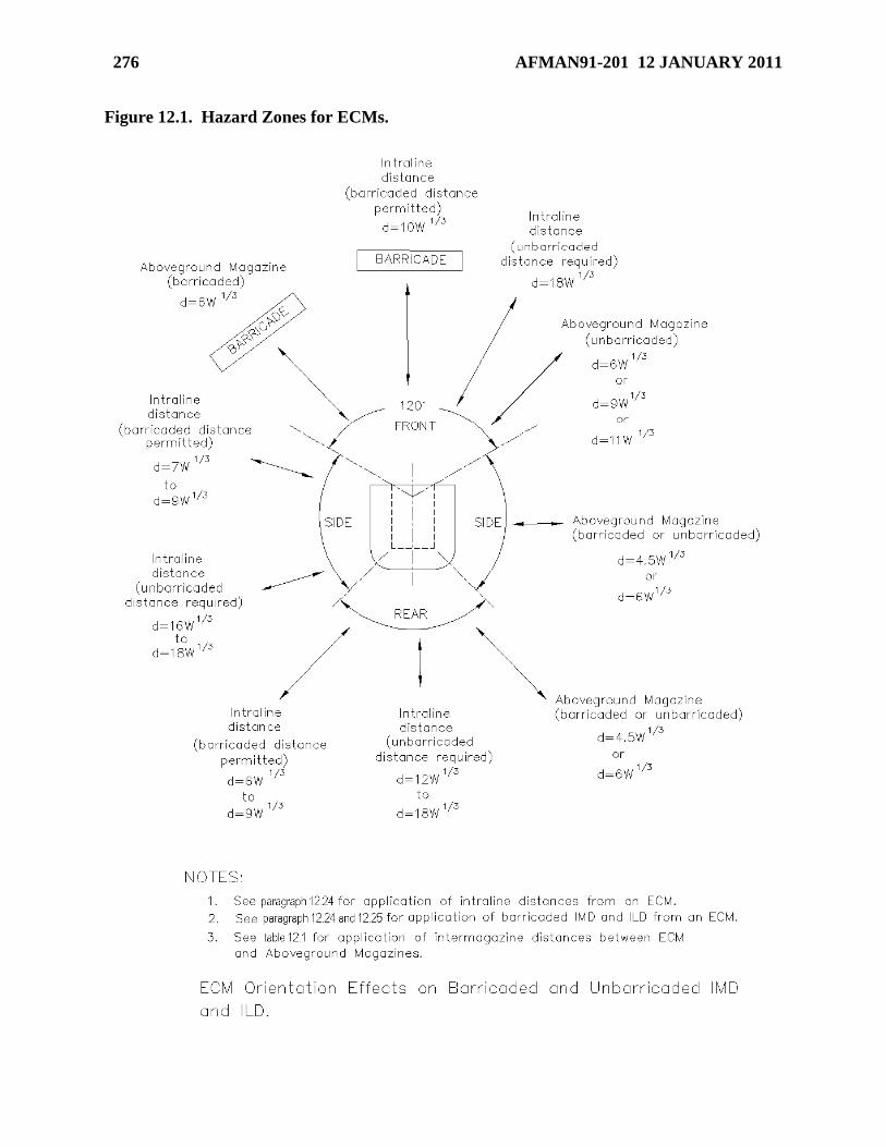
276 AFMAN91-201 12 JANUARY 2011
Figure 12.1. Hazard Zones for ECMs.
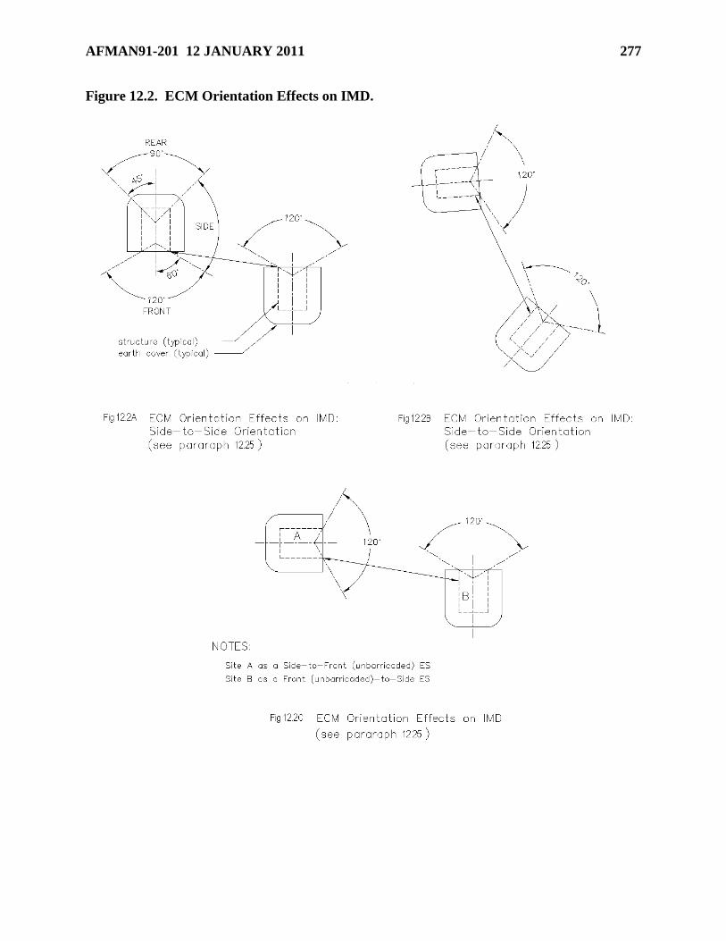
AFMAN91-201 12 JANUARY 2011 277
Figure 12.2. ECM Orientation Effects on IMD.
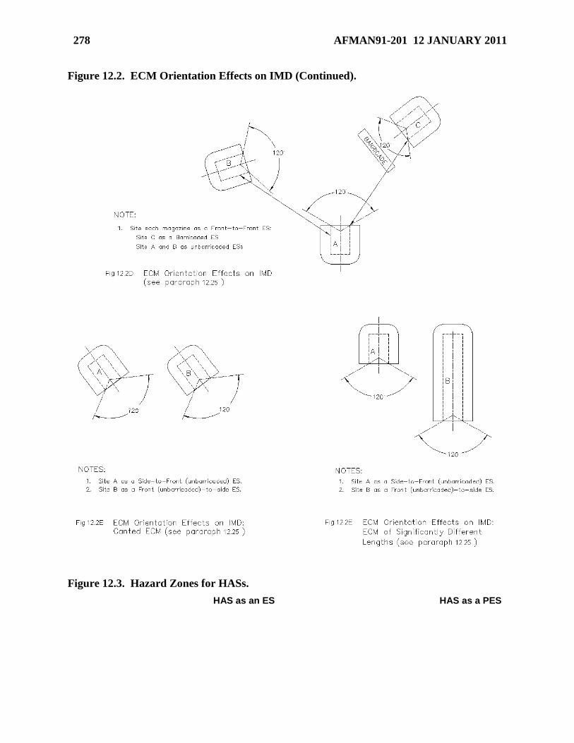
278 AFMAN91-201 12 JANUARY 2011
Figure 12.2. ECM Orientation Effects on IMD (Continued).
Figure 12.3. Hazard Zones for HASs.
HAS as an ES HAS as a PES
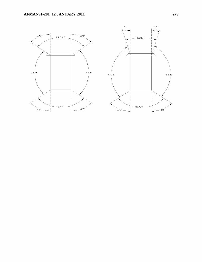
AFMAN91-201 12 JANUARY 2011 279
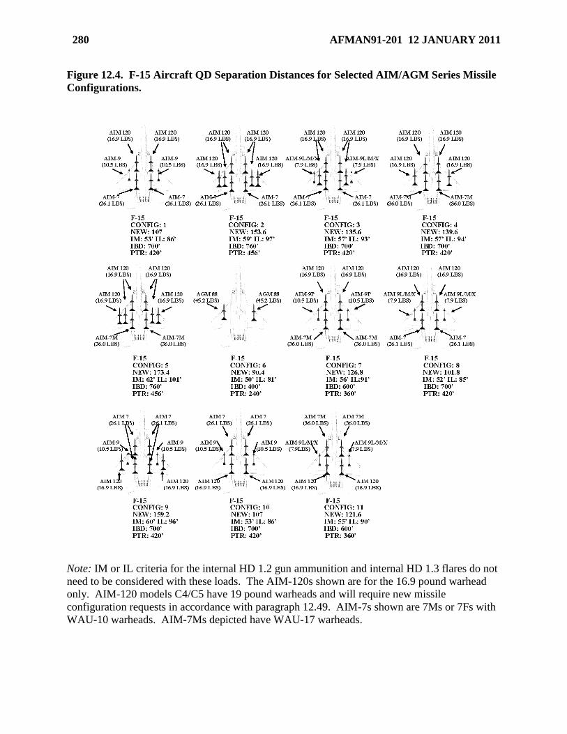
280 AFMAN91-201 12 JANUARY 2011
Figure 12.4. F-15 Aircraft QD Separation Distances for Selected AIM/AGM Series Missile
Configurations.
Note: IM or IL criteria for the internal HD 1.2 gun ammunition and internal HD 1.3 flares do not
need to be considered with these loads. The AIM-120s shown are for the 16.9 pound warhead
only. AIM-120 models C4/C5 have 19 pound warheads and will require new missile
configuration requests in accordance with paragraph 12.49. AIM-7s shown are 7Ms or 7Fs with
WAU-10 warheads. AIM-7Ms depicted have WAU-17 warheads.
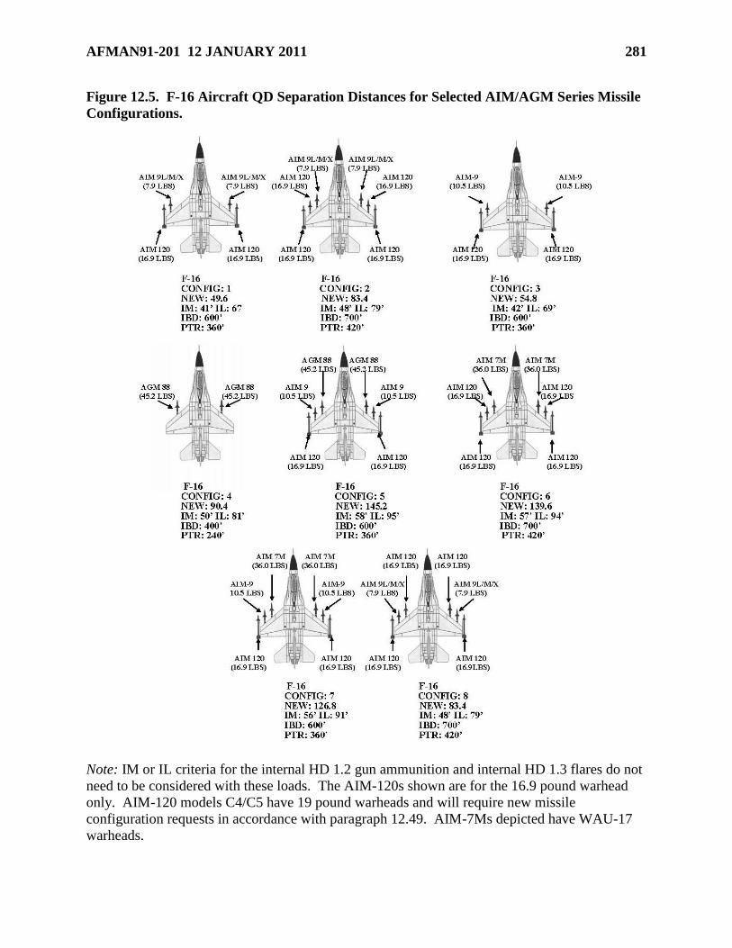
AFMAN91-201 12 JANUARY 2011 281
Figure 12.5. F-16 Aircraft QD Separation Distances for Selected AIM/AGM Series Missile
Configurations.
Note: IM or IL criteria for the internal HD 1.2 gun ammunition and internal HD 1.3 flares do not
need to be considered with these loads. The AIM-120s shown are for the 16.9 pound warhead
only. AIM-120 models C4/C5 have 19 pound warheads and will require new missile
configuration requests in accordance with paragraph 12.49. AIM-7Ms depicted have WAU-17
warheads.
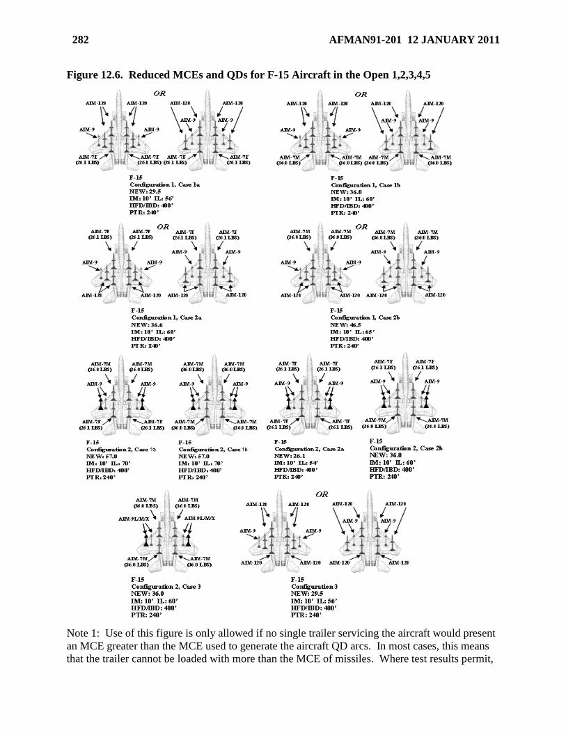
282 AFMAN91-201 12 JANUARY 2011
Figure 12.6. Reduced MCEs and QDs for F-15 Aircraft in the Open 1,2,3,4,5
Note 1: Use of this figure is only allowed if no single trailer servicing the aircraft would present
an MCE greater than the MCE used to generate the aircraft QD arcs. In most cases, this means
that the trailer cannot be loaded with more than the MCE of missiles. Where test results permit,
AFMAN91-201 12 JANUARY 2011 283
such as in the case of a single layer of AIM-120 missiles loaded in alternating directions on a
single trailer, reduced trailer MCEs may be applied. In that specific case, the trailer MCE is a
single AIM-120 missile. IM or IL criteria for the internal HD 1.2 gun ammunition and internal
HD 1.3 flares do not need to be considered with these loads.
Note 2: Configuration numbers do not correspond to configuration numbers in Figure 12.7.
Note 3: Unless otherwise specified,
AIM-120s must be AIM-120, WDU-33/Bs and/or AIM-120, WDU-41/Bs
AIM-9s must be AIM-9L/M/X WDU-17s 7.9lb Warheads and/or AIM-9P, 10.5lb
Warheads
AIM-7s must be AIM-7M, WAU-17s and/or AIM-7F, WAU-10s (treat AIM-7M with
WAU-10 as AIM-7F in the table)
Note 4: Subsets of any configuration are acceptable as long as remaining missiles match type
and location shown in the configuration.
Note 5: IM for all configurations is based on the minimum aircraft separation requirement of 10
ft. If circumstances require locating aircraft at less than this distance, then lesser IM distances
may be approved by AFSC/SEW. Request approval through MAJCOM/SEW.
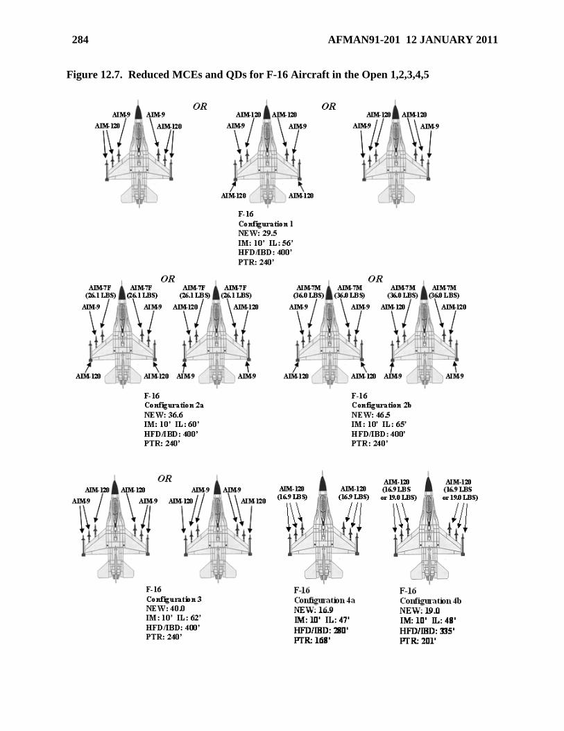
284 AFMAN91-201 12 JANUARY 2011
Figure 12.7. Reduced MCEs and QDs for F-16 Aircraft in the Open 1,2,3,4,5
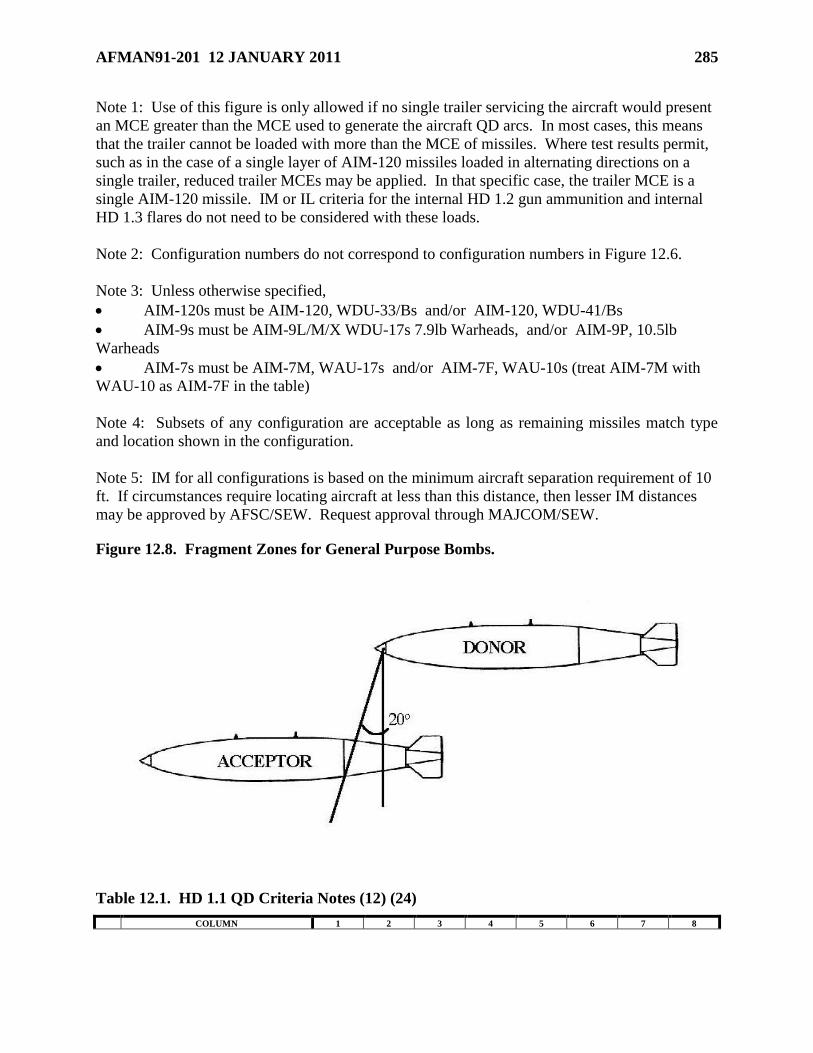
AFMAN91-201 12 JANUARY 2011 285
Note 1: Use of this figure is only allowed if no single trailer servicing the aircraft would present
an MCE greater than the MCE used to generate the aircraft QD arcs. In most cases, this means
that the trailer cannot be loaded with more than the MCE of missiles. Where test results permit,
such as in the case of a single layer of AIM-120 missiles loaded in alternating directions on a
single trailer, reduced trailer MCEs may be applied. In that specific case, the trailer MCE is a
single AIM-120 missile. IM or IL criteria for the internal HD 1.2 gun ammunition and internal
HD 1.3 flares do not need to be considered with these loads.
Note 2: Configuration numbers do not correspond to configuration numbers in Figure 12.6.
Note 3: Unless otherwise specified,
AIM-120s must be AIM-120, WDU-33/Bs and/or AIM-120, WDU-41/Bs
AIM-9s must be AIM-9L/M/X WDU-17s 7.9lb Warheads, and/or AIM-9P, 10.5lb
Warheads
AIM-7s must be AIM-7M, WAU-17s and/or AIM-7F, WAU-10s (treat AIM-7M with
WAU-10 as AIM-7F in the table)
Note 4: Subsets of any configuration are acceptable as long as remaining missiles match type
and location shown in the configuration.
Note 5: IM for all configurations is based on the minimum aircraft separation requirement of 10
ft. If circumstances require locating aircraft at less than this distance, then lesser IM distances
may be approved by AFSC/SEW. Request approval through MAJCOM/SEW.
Figure 12.8. Fragment Zones for General Purpose Bombs.
Table 12.1. HD 1.1 QD Criteria Notes (12) (24)
COLUMN 1 2 3 4 5 6 7 8
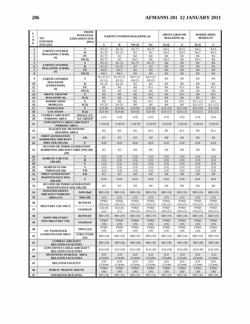
286 AFMAN91-201 12 JANUARY 2011
L
I
N
E
TO:
EXPOSED
SITE (ES)
FROM:
POTENTIAL
EXPLOSION SITE
(PES)
EARTH COVERED MAGAZINE (4) ABOVE GROUND
MAGAZINE (6)
BARRICADED
MODULES
S R FB (3) FU B (3) U B (5) U
1 EARTH COVERED
MAGAZINE (7-BAR)
(4)
S K1.25 K1.25 K2.75 K2.75 K4.5 K4.5 K4.5 K4.5
2 R K1.25 K1.25 K2 K2 K4.5 K4.5 K4.5 K4.5
3 FU K2.75 K2 K6 K6 K6 K6 K6 K6
4 FB (3) K2.75 K2 K4.5 K6 K4.5 K6 K4.5 K6
5 EARTH COVERED
MAGAZINE (3-BAR)
(4)
S K1.25 K1.25 K2.75 K2.75 K6 K6 K6 K6
6 R K1.25 K1.25 K2 K2 K6 K6 K6 K6
7 FU K4.5 K4.5 K6 K9 K6 K9 K6 K9
8 FB (3) K4.5 K4.5 K6 K6 K6 K6 K6 K6
9 EARTH COVERED
MAGAZINE
(UNDEFINED)
(4)
S K1.25 (1)
K2 (2)
K1.25 (1)
K2 (2)
K4.5 (1)
K6 (2)
K4.5 (1)
K6 (2) K6 K6 K6 K6
10 R K1.25 K1.25 K2 K2 K6 K6 K6 K6
11 FU K6 K6 K6 K11 K6 K11 K6 K11
12 FB (3) K6 K6 K6 K6 K6 K6 K6 K6
13 ABOVE GROUND
MAGAZINE (6)
U K6 K6 K6 K11 K6 K11 K6 K11
14 B (3) K6 K6 K6 K6 K6 K6 K6 K6
15 BARRICADED
MODULES
U K6 K6 K6 K11 K6 K11 K1.1 (7) K11
16 B (5) K1.25 K1.25 K6 K6 K6 K6 K1.1 (7) K1.1 (7)
17 OPERATING
LOCATION
U ILD (8) ILD (8) ILD (8) ILD (8) ILD (10) ILD (10) ILD (10) ILD (10)
18 B (3) ILD (9) ILD (9) ILD (9) ILD (9) ILD (11) ILD (11) ILD (11) ILD (11)
19 COMBAT AIRCRAFT
PARKING AREA
SINGLE A/C (13) (13) (13) (13) (13) (13) (13) (13)
20 A/C GROUP
21 EXPLOSIVES CARGO AIRCRAFT
PARKING AREA (13)(16) (13)(16) (13)(16) (13)(16) (13)(16) (13)(16) (13)(16) (13)(16)
22 FLIGHTLINE MUNITIONS
HOLDING AREA K6 K6 K6 K11 K6 K11 K6 K11
23 FIRST GENERATION
HARDENED AIRCRAFT
SHELTER (30) (29)
S/R K5 K5 K8 K8 K8 K8 K8 K8
24 F K18 K18 K18 K18 K18 K18 K18 K18
25
SECOND OR THIRD GENERATION
HARDENED AIRCRAFT SHELTER (30)
(29)
K5 K5 K8 K8 K8 K8 K8 K8
26 KOREAN TAB VEE
(30) (29)
S (13) (13) (13) (13) (13) (13) (13) (13)
27 R (13) (13) (13) (13) (13) (13) (13) (13)
28 F (13) (13) (13) (13) (13) (13) (13) (13)
29 KOREAN FLOW-
THROUGH (30)
S (13) (13) (13) (13) (13) (13) (13) (13)
30 F/R (13) (13) (13) (13) (13) (13) (13) (13)
31 FIRST GENERATION
MAINTENANCE HAS
(30) (29)
S/R K5 K5 K8 K8 K8 K8 K8 K8
32 F K18 K18 K18 K18 K18 K18 K18 K18
33 SECOND OR THIRD GENERATION
MAINTENANCE HAS (30) (29) K5 K5 K8 K8 K8 K8 K8 K8
34 NON-EXPLOSIVES
AIRCRAFT PARKING
AREA (17)
NON-DoD IBD (19) IBD (19) IBD (19) IBD (19) IBD (19) IBD (19) IBD (19) IBD (19)
35 DoD (18) (13) (13) (13) (13) (13) (13) (13) (13)
36
MILITARY USE ONLY
RUNWAY PTRD
(19) (21)
PTRD
(19) (21)
PTRD
(19) (21)
PTRD
(19) (21)
PTRD
(19) (21)
PTRD
(19) (21)
PTRD
(19) (21)
PTRD
(19) (21)
37 TAXIWAY ILD (8)
(21)
ILD (8)
(21)
PTRD
(19) (21)
PTRD
(19) (21)
PTRD
(19) (21)
PTRD
(19) (21)
PTRD
(19) (21)
PTRD
(19) (21)
38 JOINT MILITARY/
NON-MILITARY USE
RUNWAY IBD (19) IBD (19) IBD (19) IBD (19) IBD (19) IBD (19) IBD (19) IBD (19)
39 TAXIWAY PTRD
(19)
PTRD
(19)
PTRD
(19)
PTRD
(19)
PTRD
(19)
PTRD
(19)
PTRD
(19)
PTRD
(19)
40 A/C PASSENGER
LOAD/UNLOAD AREA
OPEN (22) PTRD
(19)
PTRD
(19)
PTRD
(19)
PTRD
(19)
PTRD
(19)
PTRD
(19)
PTRD
(19)
PTRD
(19)
41 STRUCTURE
(23) IBD (19) IBD (19) IBD (19) IBD (19) IBD (19) IBD (19) IBD (19) IBD (19)
42 COMBAT AIRCRAFT
RELATED FACILITIES IBD (38) IBD (38) IBD (38) IBD (38) IBD (38) IBD (38) IBD (38) IBD (38)
43 EXPLOSIVES CARGO AIRCRAFT
RELATED FACILITIES ILD (39) ILD (39) ILD (39) ILD (39) ILD (39) ILD (39) ILD (39) ILD (39)
44 MUNITIONS STORAGE AREA
RELATED FACILITIES
ILD
(37)(40)
ILD
(37)(40)
ILD
(37)(40)
ILD
(37)(40)
ILD
(37)(40)
ILD
(37)(40)
ILD
(37)(40)
ILD
(37)(40)
45 RELATED FACILITY ILD
(37)(40)
ILD
(37)(40)
ILD
(37)(40)
ILD
(37)(40)
ILD
(37)(40)
ILD
(37)(40)
ILD
(37)(40)
ILD
(37)(40)
46 PUBLIC TRAFFIC ROUTE PTRD
(36)
PTRD
(36)
PTRD
(36)
PTRD
(36)
PTRD
(36)
PTRD
(36)
PTRD
(36)
PTRD
(36)
47 INHABITED BUILDING IBD (36) IBD (36) IBD (36) IBD (36) IBD (36) IBD (36) IBD (36) IBD (36)
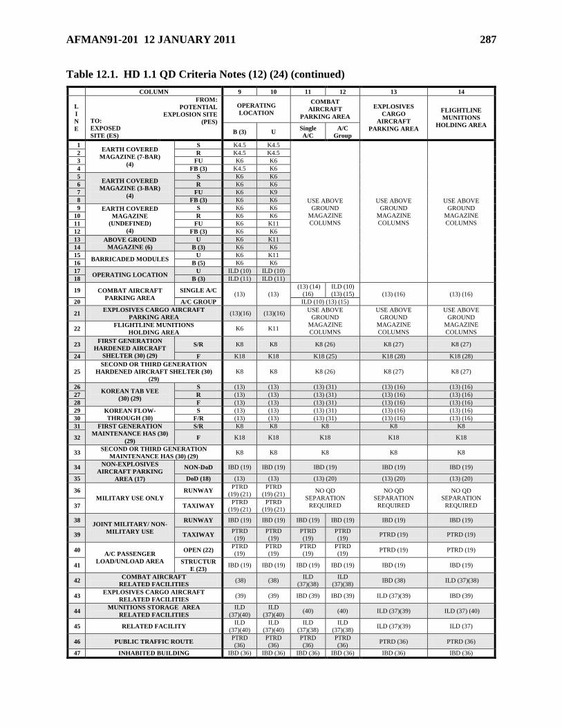
AFMAN91-201 12 JANUARY 2011 287
Table 12.1. HD 1.1 QD Criteria Notes (12) (24) (continued)
COLUMN 9 10 11 12 13 14
L
I
N
E
TO:
EXPOSED
SITE (ES)
FROM:
POTENTIAL
EXPLOSION SITE
(PES)
OPERATING
LOCATION
COMBAT
AIRCRAFT
PARKING AREA
EXPLOSIVES
CARGO
AIRCRAFT
PARKING AREA
FLIGHTLINE
MUNITIONS
HOLDING AREA B (3) U
Single
A/C
A/C
Group
1 EARTH COVERED
MAGAZINE (7-BAR)
(4)
S K4.5 K4.5
USE ABOVE
GROUND
MAGAZINE
COLUMNS
USE ABOVE
GROUND
MAGAZINE
COLUMNS
USE ABOVE
GROUND
MAGAZINE
COLUMNS
2 R K4.5 K4.5
3 FU K6 K6
4 FB (3) K4.5 K6
5 EARTH COVERED
MAGAZINE (3-BAR)
(4)
S K6 K6
6 R K6 K6
7 FU K6 K9
8 FB (3) K6 K6
9 EARTH COVERED
MAGAZINE
(UNDEFINED)
(4)
S K6 K6
10 R K6 K6
11 FU K6 K11
12 FB (3) K6 K6
13 ABOVE GROUND
MAGAZINE (6)
U K6 K11
14 B (3) K6 K6
15 BARRICADED MODULES
U K6 K11
16 B (5) K6 K6
17 OPERATING LOCATION
U ILD (10) ILD (10)
18 B (3) ILD (11) ILD (11)
19 COMBAT AIRCRAFT
PARKING AREA
SINGLE A/C (13) (13)
(13) (14)
(16)
ILD (10)
(13) (15) (13) (16) (13) (16)
20 A/C GROUP ILD (10) (13) (15)
21 EXPLOSIVES CARGO AIRCRAFT
PARKING AREA (13)(16) (13)(16)
USE ABOVE
GROUND
MAGAZINE
COLUMNS
USE ABOVE
GROUND
MAGAZINE
COLUMNS
USE ABOVE
GROUND
MAGAZINE
COLUMNS 22
FLIGHTLINE MUNITIONS
HOLDING AREA K6 K11
23 FIRST GENERATION
HARDENED AIRCRAFT
SHELTER (30) (29)
S/R K8 K8 K8 (26) K8 (27) K8 (27)
24 F K18 K18 K18 (25) K18 (28) K18 (28)
25
SECOND OR THIRD GENERATION
HARDENED AIRCRAFT SHELTER (30)
(29)
K8 K8 K8 (26) K8 (27) K8 (27)
26 KOREAN TAB VEE
(30) (29)
S (13) (13) (13) (31) (13) (16) (13) (16)
27 R (13) (13) (13) (31) (13) (16) (13) (16)
28 F (13) (13) (13) (31) (13) (16) (13) (16)
29 KOREAN FLOW-
THROUGH (30)
S (13) (13) (13) (31) (13) (16) (13) (16)
30 F/R (13) (13) (13) (31) (13) (16) (13) (16)
31 FIRST GENERATION
MAINTENANCE HAS (30)
(29)
S/R K8 K8 K8 K8 K8
32 F K18 K18 K18 K18 K18
33 SECOND OR THIRD GENERATION
MAINTENANCE HAS (30) (29) K8 K8 K8 K8 K8
34 NON-EXPLOSIVES
AIRCRAFT PARKING
AREA (17)
NON-DoD IBD (19) IBD (19) IBD (19) IBD (19) IBD (19)
35 DoD (18) (13) (13) (13) (20) (13) (20) (13) (20)
36
MILITARY USE ONLY
RUNWAY PTRD
(19) (21)
PTRD
(19) (21) NO QD
SEPARATION
REQUIRED
NO QD
SEPARATION
REQUIRED
NO QD
SEPARATION
REQUIRED 37 TAXIWAY PTRD
(19) (21)
PTRD
(19) (21)
38 JOINT MILITARY/ NON-
MILITARY USE
RUNWAY IBD (19) IBD (19) IBD (19) IBD (19) IBD (19) IBD (19)
39 TAXIWAY PTRD
(19)
PTRD
(19)
PTRD
(19)
PTRD
(19) PTRD (19) PTRD (19)
40 A/C PASSENGER
LOAD/UNLOAD AREA
OPEN (22) PTRD
(19)
PTRD
(19)
PTRD
(19)
PTRD
(19) PTRD (19) PTRD (19)
41 STRUCTUR
E (23) IBD (19) IBD (19) IBD (19) IBD (19) IBD (19) IBD (19)
42 COMBAT AIRCRAFT
RELATED FACILITIES (38) (38)
ILD
(37)(38)
ILD
(37)(38) IBD (38) ILD (37)(38)
43 EXPLOSIVES CARGO AIRCRAFT
RELATED FACILITIES (39) (39) IBD (39) IBD (39) ILD (37)(39) IBD (39)
44 MUNITIONS STORAGE AREA
RELATED FACILITIES
ILD
(37)(40)
ILD
(37)(40) (40) (40) ILD (37)(39) ILD (37) (40)
45 RELATED FACILITY ILD
(37)(40)
ILD
(37)(40)
ILD
(37)(38)
ILD
(37)(38) ILD (37)(39) ILD (37)
46 PUBLIC TRAFFIC ROUTE PTRD
(36)
PTRD
(36)
PTRD
(36)
PTRD
(36) PTRD (36) PTRD (36)
47 INHABITED BUILDING IBD (36) IBD (36) IBD (36) IBD (36) IBD (36) IBD (36)
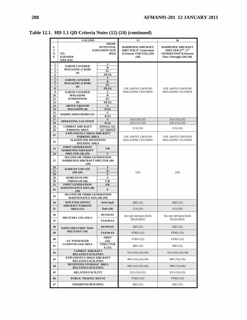
288 AFMAN91-201 12 JANUARY 2011
Table 12.1. HD 1.1 QD Criteria Notes (12) (24) (continued)
COLUMN 15 16
L
I
N
E
TO:
EXPOSED
SITE (ES)
FROM:
POTENTIAL
EXPLOSION SITE
(PES)
HARDENED AIRCRAFT
SHELTER (1st Generation
& Korean TAB VEE) (29)
(30)
HARDENED AIRCRAFT
SHELTER (2nd / 3rd
GENERATION & Korean
Flow-Through) (29) (30)
1 EARTH COVERED
MAGAZINE (7-BAR)
(4)
S
USE ABOVE GROUND
MAGAZINE COLUMNS
USE ABOVE GROUND
MAGAZINE COLUMNS
2 R
3 FU
4 FB (3)
5 EARTH COVERED
MAGAZINE (3-BAR)
(4)
S
6 R
7 FU
8 FB (3)
9 EARTH COVERED
MAGAZINE
(UNDEFINED)
(4)
S
10 R
11 FU
12 FB (3)
13 ABOVE GROUND
MAGAZINE (6)
U
14 B (3)
15 BARRICADED MODULES
U
16 B (5)
17 OPERATING LOCATION
U ILD (10) (32) ILD (10) (33)
18 B (3) ILD (11) (32) ILD (11) (33)
19 COMBAT AIRCRAFT
PARKING AREA
SINGLE A/C (13) (16) (13) (16)
20 A/C GROUP
21 EXPLOSIVES CARGO AIRCRAFT
PARKING AREA USE ABOVE GROUND
MAGAZINE COLUMNS
USE ABOVE GROUND
MAGAZINE COLUMNS 22
FLIGHTLINE MUNITIONS
HOLDING AREA
23 FIRST GENERATION
HARDENED AIRCRAFT
SHELTER (30) (29)
S/R
(34) (34)
24 F
25
SECOND OR THIRD GENERATION
HARDENED AIRCRAFT SHELTER (30)
(29)
26 KOREAN TAB VEE
(30) (29)
S
27 R
28 F
29 KOREAN FLOW-
THROUGH (30)
S
30 F/R
31 FIRST GENERATION
MAINTENANCE HAS (30)
(29)
S/R
32 F
33 SECOND OR THIRD GENERATION
MAINTENANCE HAS (30) (29)
34 NON-EXPLOSIVES
AIRCRAFT PARKING
AREA (17)
NON-DoD IBD (32) IBD (33)
35 DoD (18) (13) (20) (13) (20)
36 MILITARY USE ONLY
RUNWAY NO QD SEPARATION
REQUIRED
NO QD SEPARATION
REQUIRED 37 TAXIWAY
38 JOINT MILITARY/ NON-
MILITARY USE
RUNWAY IBD (32) IBD (33)
39 TAXIWAY PTRD (32) PTRD (33)
40 A/C PASSENGER
LOAD/UNLOAD AREA
OPEN
(22) PTRD (32) PTRD (33)
41 STRUCTUR
E (23) IBD (32) IBD (33)
42 COMBAT AIRCRAFT
RELATED FACILITIES ILD (10) (32) (38) ILD (10) (33) (38)
43 EXPLOSIVES CARGO AIRCRAFT
RELATED FACILITIES IBD (32) (35) (39) IBD (33) (39)
44 MUNITIONS STORAGE AREA
RELATED FACILITIES IBD (32) (35) (40) IBD (33) (40)
45 RELATED FACILITY ILD (10) (32) ILD (10) (33)
46 PUBLIC TRAFFIC ROUTE PTRD (32) PTRD (33)
47 INHABITED BUILDING IBD (32) IBD (33)
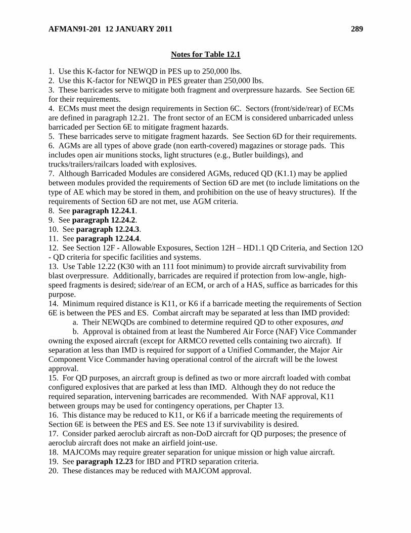
AFMAN91-201 12 JANUARY 2011 289
Notes for Table 12.1
1. Use this K-factor for NEWQD in PES up to 250,000 lbs.
2. Use this K-factor for NEWQD in PES greater than 250,000 lbs.
3. These barricades serve to mitigate both fragment and overpressure hazards. See Section 6E
for their requirements.
4. ECMs must meet the design requirements in Section 6C. Sectors (front/side/rear) of ECMs
are defined in paragraph 12.21. The front sector of an ECM is considered unbarricaded unless
barricaded per Section 6E to mitigate fragment hazards.
5. These barricades serve to mitigate fragment hazards. See Section 6D for their requirements.
6. AGMs are all types of above grade (non earth-covered) magazines or storage pads. This
includes open air munitions stocks, light structures (e.g., Butler buildings), and
trucks/trailers/railcars loaded with explosives.
7. Although Barricaded Modules are considered AGMs, reduced QD (K1.1) may be applied
between modules provided the requirements of Section 6D are met (to include limitations on the
type of AE which may be stored in them, and prohibition on the use of heavy structures). If the
requirements of Section 6D are not met, use AGM criteria.
8. See paragraph 12.24.1.
9. See paragraph 12.24.2.
10. See paragraph 12.24.3.
11. See paragraph 12.24.4.
12. See Section 12F - Allowable Exposures, Section 12H – HD1.1 QD Criteria, and Section 12O
- QD criteria for specific facilities and systems.
13. Use Table 12.22 (K30 with an 111 foot minimum) to provide aircraft survivability from
blast overpressure. Additionally, barricades are required if protection from low-angle, high-
speed fragments is desired; side/rear of an ECM, or arch of a HAS, suffice as barricades for this
purpose.
14. Minimum required distance is K11, or K6 if a barricade meeting the requirements of Section
6E is between the PES and ES. Combat aircraft may be separated at less than IMD provided:
a. Their NEWQDs are combined to determine required QD to other exposures, and
b. Approval is obtained from at least the Numbered Air Force (NAF) Vice Commander
owning the exposed aircraft (except for ARMCO revetted cells containing two aircraft). If
separation at less than IMD is required for support of a Unified Commander, the Major Air
Component Vice Commander having operational control of the aircraft will be the lowest
approval.
15. For QD purposes, an aircraft group is defined as two or more aircraft loaded with combat
configured explosives that are parked at less than IMD. Although they do not reduce the
required separation, intervening barricades are recommended. With NAF approval, K11
between groups may be used for contingency operations, per Chapter 13.
16. This distance may be reduced to K11, or K6 if a barricade meeting the requirements of
Section 6E is between the PES and ES. See note 13 if survivability is desired.
17. Consider parked aeroclub aircraft as non-DoD aircraft for QD purposes; the presence of
aeroclub aircraft does not make an airfield joint-use.
18. MAJCOMs may require greater separation for unique mission or high value aircraft.
19. See paragraph 12.23 for IBD and PTRD separation criteria.
20. These distances may be reduced with MAJCOM approval.
290 AFMAN91-201 12 JANUARY 2011
21. When required at overseas locations only, use K4.5 (or D=1.8Q1/3, where D is the distance
in meters and Q equals the NEWQD in kilograms). The use of this reduced separation depends
on operational necessity, providing the commander accepts the transient risk to military aircraft
movements. If siting facilities, the MAJCOM/CC or CV must provide AFSC/SEW a letter
listing all installations at which this separation distance will apply and state acceptance of
transient risk to military aircraft movements.
22. Use this row for locations in the open where passengers enplane and deplane.
23. Use this row if a structure is included where passengers assemble, such as a passenger
terminal building.
24. Use this table for siting HD 1.5 (see paragraph 12.13.5).
25. This distance provides aircraft survivability from blast overpressure. For IMD protection,
this distance may be reduced to K9, or K6 if a barricade meeting the requirements of Section 6E
is between the PES and ES.
26. This distance provides aircraft survivability from blast overpressure. For IMD protection,
this distance may be reduced to K2.75.
27. This distance provides aircraft survivability from blast overpressure. For IMD protection,
this distance may be reduced to K2.75.
28. This distance provides aircraft survivability from blast overpressure. For IMD protection,
this distance may be reduced to K9, or K6 if a barricade meeting the requirements of Section 6E
is between the PES and ES.
29. Separations are based on shelter doors remaining closed, except for aircraft towing, fueling,
servicing, run up, or taxi, and during concurrent servicing operations or short periods when
maintenance equipment or munitions are being moved into or out of shelters. If doors are left
open for extended periods, normal combat aircraft parking area apply to and from the front. as a
PES, parenthetical (xx) fragment distances do not apply except out the front of a Korean TAB
VEE HAS and out the front/rear of a Korean Flow-Through HAS.
30. HASs must meet the category requirements in paragraph 12.51.1. Sectors (front/side/rear)
of HASs are defined in paragraph 12.21. A HAS arch or rear wall may be considered as a
barricade for application of K6, when applicable. The front sector of an HAS is considered
unbarricaded unless barricaded per Section 6E to mitigate fragment hazards. (See para 12.51.)
31. This distance provides aircraft survivability. For IMD protection, this distance may be
reduced to K11, or K6 if a barricade meeting the requirements of Section 6E is between the PES
and ES.
32. Use Table 12.25B
33. Use Table 12.25A.
34. Use Table 12.24 (aircraft survivability) for separation between HASs, and between HASs
and HAS Ready Service ECMs/AGMs. The MAJCOM/CC/CV may approve the use of Table
12.23 (IMD equivalent separation).
35. IBD out the side is K62; IBD out the rear is K40; IBD out the front is K50.
36. See paragraph 12.23.
37. See paragraph 12.24.
38. See paragraph 12.40.
39. See paragraph 12.41.
40. See paragraph 12.42.
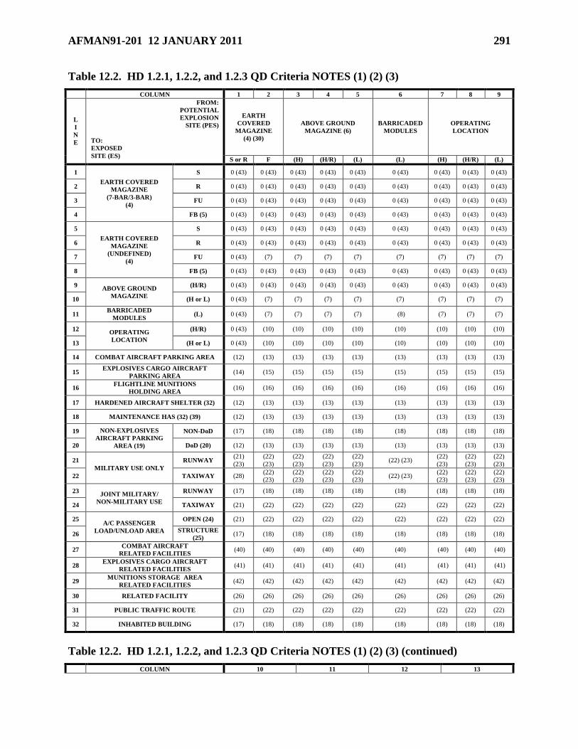
AFMAN91-201 12 JANUARY 2011 291
Table 12.2. HD 1.2.1, 1.2.2, and 1.2.3 QD Criteria NOTES (1) (2) (3)
COLUMN 1 2 3 4 5 6 7 8 9
L
I
N
E
FROM:
POTENTIAL
EXPLOSION
SITE (PES)
TO:
EXPOSED
SITE (ES)
EARTH
COVERED
MAGAZINE
(4) (30)
ABOVE GROUND
MAGAZINE (6)
BARRICADED
MODULES
OPERATING
LOCATION
S or R F (H) (H/R) (L) (L) (H) (H/R) (L)
1
EARTH COVERED
MAGAZINE
(7-BAR/3-BAR)
(4)
S 0 (43) 0 (43) 0 (43) 0 (43) 0 (43) 0 (43) 0 (43) 0 (43) 0 (43)
2 R 0 (43) 0 (43) 0 (43) 0 (43) 0 (43) 0 (43) 0 (43) 0 (43) 0 (43)
3 FU 0 (43) 0 (43) 0 (43) 0 (43) 0 (43) 0 (43) 0 (43) 0 (43) 0 (43)
4 FB (5) 0 (43) 0 (43) 0 (43) 0 (43) 0 (43) 0 (43) 0 (43) 0 (43) 0 (43)
5
EARTH COVERED
MAGAZINE
(UNDEFINED)
(4)
S 0 (43) 0 (43) 0 (43) 0 (43) 0 (43) 0 (43) 0 (43) 0 (43) 0 (43)
6 R 0 (43) 0 (43) 0 (43) 0 (43) 0 (43) 0 (43) 0 (43) 0 (43) 0 (43)
7 FU 0 (43) (7) (7) (7) (7) (7) (7) (7) (7)
8 FB (5) 0 (43) 0 (43) 0 (43) 0 (43) 0 (43) 0 (43) 0 (43) 0 (43) 0 (43)
9 ABOVE GROUND
MAGAZINE
(H/R) 0 (43) 0 (43) 0 (43) 0 (43) 0 (43) 0 (43) 0 (43) 0 (43) 0 (43)
10 (H or L) 0 (43) (7) (7) (7) (7) (7) (7) (7) (7)
11 BARRICADED
MODULES (L) 0 (43) (7) (7) (7) (7) (8) (7) (7) (7)
12 OPERATING
LOCATION
(H/R) 0 (43) (10) (10) (10) (10) (10) (10) (10) (10)
13 (H or L) 0 (43) (10) (10) (10) (10) (10) (10) (10) (10)
14 COMBAT AIRCRAFT PARKING AREA (12) (13) (13) (13) (13) (13) (13) (13) (13)
15 EXPLOSIVES CARGO AIRCRAFT
PARKING AREA (14) (15) (15) (15) (15) (15) (15) (15) (15)
16 FLIGHTLINE MUNITIONS
HOLDING AREA (16) (16) (16) (16) (16) (16) (16) (16) (16)
17 HARDENED AIRCRAFT SHELTER (32) (12) (13) (13) (13) (13) (13) (13) (13) (13)
18 MAINTENANCE HAS (32) (39) (12) (13) (13) (13) (13) (13) (13) (13) (13)
19 NON-EXPLOSIVES
AIRCRAFT PARKING
AREA (19)
NON-DoD (17) (18) (18) (18) (18) (18) (18) (18) (18)
20 DoD (20) (12) (13) (13) (13) (13) (13) (13) (13) (13)
21
MILITARY USE ONLY
RUNWAY (21)
(23)
(22)
(23)
(22)
(23)
(22)
(23)
(22)
(23) (22) (23)
(22)
(23)
(22)
(23)
(22)
(23)
22 TAXIWAY (28) (22)
(23)
(22)
(23)
(22)
(23)
(22)
(23) (22) (23)
(22)
(23)
(22)
(23)
(22)
(23)
23 JOINT MILITARY/
NON-MILITARY USE
RUNWAY (17) (18) (18) (18) (18) (18) (18) (18) (18)
24 TAXIWAY (21) (22) (22) (22) (22) (22) (22) (22) (22)
25 A/C PASSENGER
LOAD/UNLOAD AREA
OPEN (24) (21) (22) (22) (22) (22) (22) (22) (22) (22)
26 STRUCTURE
(25) (17) (18) (18) (18) (18) (18) (18) (18) (18)
27 COMBAT AIRCRAFT
RELATED FACILITIES (40) (40) (40) (40) (40) (40) (40) (40) (40)
28 EXPLOSIVES CARGO AIRCRAFT
RELATED FACILITIES (41) (41) (41) (41) (41) (41) (41) (41) (41)
29 MUNITIONS STORAGE AREA
RELATED FACILITIES (42) (42) (42) (42) (42) (42) (42) (42) (42)
30 RELATED FACILITY (26) (26) (26) (26) (26) (26) (26) (26) (26)
31 PUBLIC TRAFFIC ROUTE (21) (22) (22) (22) (22) (22) (22) (22) (22)
32 INHABITED BUILDING (17) (18) (18) (18) (18) (18) (18) (18) (18)
Table 12.2. HD 1.2.1, 1.2.2, and 1.2.3 QD Criteria NOTES (1) (2) (3) (continued)
COLUMN 10 11 12 13
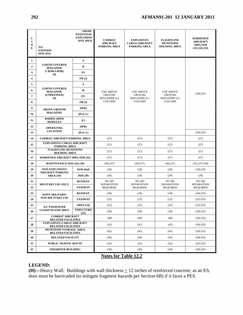
292 AFMAN91-201 12 JANUARY 2011
L
I
N
E
FROM:
POTENTIAL
EXPLOSION
SITE (PES)
TO:
EXPOSED
SITE (ES)
COMBAT
AIRCRAFT
PARKING AREA
EXPLOSIVES
CARGO AIRCRAFT
PARKING AREA
FLIGHTLINE
MUNITIONS
HOLDING AREA
HARDENED
AIRCRAFT
SHELTER
(31) (32) (33)
1
EARTH COVERED
MAGAZINE
(7-BAR/3-BAR)
(4)
S
USE ABOVE
GROUND
MAGAZINE (L)
COLUMN
USE ABOVE
GROUND
MAGAZINE (L)
COLUMN
USE ABOVE
GROUND
MAGAZINE (L)
COLUMN
(34) (35)
2 R
3 FU
4 FB (5)
5
EARTH COVERED
MAGAZINE
(UNDEFINED)
(4)
S
6 R
7 FU
8 FB (5)
9 ABOVE GROUND
MAGAZINE
(H/R)
10 (H or L)
11 BARRICADED
MODULES (L)
12 OPERATING
LOCATION
(H/R)
13 (H or L) (34) (35)
14 COMBAT AIRCRAFT PARKING AREA (27) (27) (27) (27)
15 EXPLOSIVES CARGO AIRCRAFT
PARKING AREA (27) (27) (27) (27)
16 FLIGHTLINE MUNITIONS
HOLDING AREA (27) (27) (27) (27)
17 HARDENED AIRCRAFT SHELTER (32) (27) (27) (27) (27)
18 MAINTENANCE HAS (32) (39) (36) (37) (36) (37) (36) (37) (35) (37) (38)
19 NON-EXPLOSIVES
AIRCRAFT PARKING
AREA (19)
NON-DoD (18) (18) (18) (18) (35)
20 DoD (20) (29) (29) (29) (29)
21 MILITARY USE ONLY
RUNWAY NO QD
SEPARATION
REQUIRED
NO QD
SEPARATION
REQUIRED
NO QD
SEPARATION
REQUIRED
NO QD
SEPARATION
REQUIRED 22 TAXIWAY
23 JOINT MILITARY/
NON-MILITARY USE
RUNWAY (18) (18) (18) (18) (35)
24 TAXIWAY (22) (22) (22) (22) (35)
25 A/C PASSENGER
LOAD/UNLOAD AREA
OPEN (24) (22) (22) (22) (22) (35)
26 STRUCTURE
(25) (18) (18) (18) (18) (35)
27 COMBAT AIRCRAFT
RELATED FACILITIES (40) (40) (40) (34) (35)
28 EXPLOSIVES CARGO AIRCRAFT
RELATED FACILITIES (41) (41) (41) (18) (35)
29 MUNITIONS STORAGE AREA
RELATED FACILITIES (42) (42) (42) (18) (35)
30 RELATED FACILITY (26) (26) (26) (34) (35)
31 PUBLIC TRAFFIC ROUTE (22) (22) (22) (22) (35)
32 INHABITED BUILDING (18) (18) (18) (18) (35)
Notes for Table 12.2
LEGEND:
(H)—Heavy Wall: Buildings with wall thickness > 12 inches of reinforced concrete; as an ES,
door must be barricaded (to mitigate fragment hazards per Section 6B) if it faces a PES.
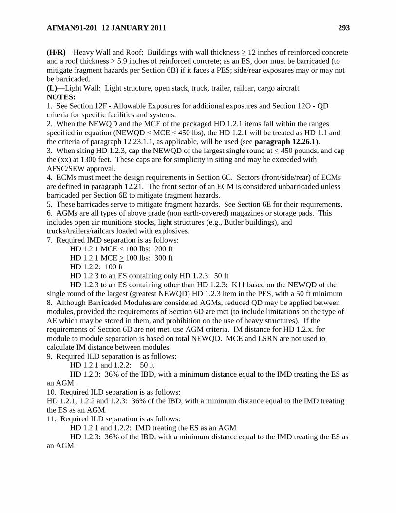
AFMAN91-201 12 JANUARY 2011 293
(H/R)—Heavy Wall and Roof: Buildings with wall thickness > 12 inches of reinforced concrete
and a roof thickness > 5.9 inches of reinforced concrete; as an ES, door must be barricaded (to
mitigate fragment hazards per Section 6B) if it faces a PES; side/rear exposures may or may not
be barricaded.
(L)—Light Wall: Light structure, open stack, truck, trailer, railcar, cargo aircraft
NOTES:
1. See Section 12F - Allowable Exposures for additional exposures and Section 12O - QD
criteria for specific facilities and systems.
2. When the NEWQD and the MCE of the packaged HD 1.2.1 items fall within the ranges
specified in equation (NEWQD < MCE < 450 lbs), the HD 1.2.1 will be treated as HD 1.1 and
the criteria of paragraph 12.23.1.1, as applicable, will be used (see paragraph 12.26.1).
3. When siting HD 1.2.3, cap the NEWQD of the largest single round at < 450 pounds, and cap
the (xx) at 1300 feet. These caps are for simplicity in siting and may be exceeded with
AFSC/SEW approval.
4. ECMs must meet the design requirements in Section 6C. Sectors (front/side/rear) of ECMs
are defined in paragraph 12.21. The front sector of an ECM is considered unbarricaded unless
barricaded per Section 6E to mitigate fragment hazards.
5. These barricades serve to mitigate fragment hazards. See Section 6E for their requirements.
6. AGMs are all types of above grade (non earth-covered) magazines or storage pads. This
includes open air munitions stocks, light structures (e.g., Butler buildings), and
trucks/trailers/railcars loaded with explosives.
7. Required IMD separation is as follows:
HD 1.2.1 MCE < 100 lbs: 200 ft
HD 1.2.1 MCE > 100 lbs: 300 ft
HD 1.2.2: 100 ft
HD 1.2.3 to an ES containing only HD 1.2.3: 50 ft
HD 1.2.3 to an ES containing other than HD 1.2.3: K11 based on the NEWQD of the
single round of the largest (greatest NEWQD) HD 1.2.3 item in the PES, with a 50 ft minimum
8. Although Barricaded Modules are considered AGMs, reduced QD may be applied between
modules, provided the requirements of Section 6D are met (to include limitations on the type of
AE which may be stored in them, and prohibition on the use of heavy structures). If the
requirements of Section 6D are not met, use AGM criteria. IM distance for HD 1.2.x. for
module to module separation is based on total NEWQD. MCE and LSRN are not used to
calculate IM distance between modules.
9. Required ILD separation is as follows:
HD 1.2.1 and 1.2.2: 50 ft
HD 1.2.3: 36% of the IBD, with a minimum distance equal to the IMD treating the ES as
an AGM.
10. Required ILD separation is as follows:
HD 1.2.1, 1.2.2 and 1.2.3: 36% of the IBD, with a minimum distance equal to the IMD treating
the ES as an AGM.
11. Required ILD separation is as follows:
HD 1.2.1 and 1.2.2: IMD treating the ES as an AGM
HD 1.2.3: 36% of the IBD, with a minimum distance equal to the IMD treating the ES as
an AGM.
294 AFMAN91-201 12 JANUARY 2011
12. Apply PTRD separation per Note 21. If aircraft survivability is mandated by the MAJCOM,
PTRD to the front of HAS with doors normally
closed is acceptable for aircraft survivability or IBD separation per Note 17 for aircraft
survivability for all other relationships.
13. Apply PTRD separation per Note 22. If aircraft survivability is mandated by the MAJCOM,
PTRD to the front of HAS with doors normally closed is acceptable for aircraft survivability or
IBD separation per Note 18 for aircraft survivability for all other relationships.
14. Apply IMD separation treating the ES as an AGM. If aircraft survivability is mandated by
the MAJCOM, IBD separation per Note 17 is required for aircraft survivability.
15. Apply IMD separation treating the ES as an AGM. If aircraft survivability is mandated by
the MAJCOM, IBD separation per Note 18 is required for aircraft survivability.
16. Apply IMD separation treating the ES as an AGM.
17. Required IBD separation is as follows:
HD 1.2.1 MCE < 100 lbs: 200 ft
HD 1.2.1 MCE > 100 lbs: 300 ft
HD 1.2.2: 100 ft
HD 1.2.3: IBD per paragraph 12.27.2.1
18. Required IBD separation is as follows:
HD 1.2.1 in a structure/truck/trailer/railcar/cargo aircraft: IBD is the larger of the IBD from
Table 12.9 or the HDD from Table 12.10
HD 1.2.1 in the open/external a/c AE/stacks on open truck/trailer/railcar: IBD is the IBD from
Table 12.9
HD 1.2.2: IBD is the IBD from Table 12.11
HD 1.2.3: IBD per paragraph 12.27.2.1
19. Consider parked aeroclub aircraft as non-DoD aircraft for QD purposes; the presence of
aeroclub aircraft does not make an airfield joint-use.
20. MAJCOMs may require greater separation for unique mission or high value aircraft.
21. Required PTRD separation is as follows:
HD 1.2.1 MCE < 100 lbs: 200 ft
HD 1.2.1 MCE > 100 lbs: 300 ft
HD 1.2.2: 100 ft
HD 1.2.3: 60% of the IBD, with a minimum distance equal to the IMD treating the ES as an
AGM (H or L)
22. Required PTRD separation is as follows:
HD 1.2.1, 1.2.2 and 1.2.3: 60% of the IBD, with a minimum distance equal to the IMD treating
the ES as an AGM (H or L).
23. When required at overseas locations only, use 125 ft. The use of this reduced separation
depends on operational necessity, providing the commander accepts the transient risk to military
aircraft movements. If siting facilities, the MAJCOM/CC or CV must provide AFSC/SEW a
letter listing all installations at which this separation distance will apply and state acceptance of
transient risk to military aircraft movements.
24. Use this row for locations in the open where passengers enplane and deplane.
25. Use this row if a structure is included where passengers assemble, such as a passenger
terminal building.
26. Treat as an Operating Location to determine required ILD separation.
AFMAN91-201 12 JANUARY 2011 295
27. No QD separation is required, unless the MAJCOM requires aircraft survivability (PTRD to
the front of HAS with doors normally closed is acceptable for aircraft survivability; use IBD
separation per Note 18 for aircraft survivability for all other relationships).
28. No QD separation is required.
29. MAJCOMs will determine required QD separation.
30. ECMs may be used to their physical capacity for HD 1.2 provided they meet separation
requirements for a minimum of 100 lbs of HD 1.1, and provided separations to other exposures
comply with applicable QD criteria.
31. Separations are based on shelter doors remaining closed, except for aircraft towing, fueling,
servicing, run up, or taxi, and during concurrent servicing operations or short periods when
maintenance equipment or munitions are being moved into or out of shelters. If doors are left
open for extended periods, normal combat aircraft parking area apply from the front.
32. HASs must meet the category requirements in paragraph 12.51.1. Sectors (front/side/rear)
of HASs are defined in paragraph 12.21. The front sector of an HAS is considered unbarricaded
unless barricaded per Section 6E to mitigate fragment hazards. (See paragraph 12.51.)
33. First, Second and Third Generation HASs, and Korean TAB VEE HASs, sited for HD 1.2.1
MCE < 110 lbs, HD 1.2.2, or HD 1.2.3 LSRN<110 lbs do not generate a QD clear zone except
out the front. Korean Flow-Through HASs sited for HD 1.2.1 MCE < 110 lbs, HD 1.2.2, or HD
1.2.3 LSRN<110 lbs do not generate a QD clear zone except out the front and rear. Fire
protection distances still apply.
34. For a front exposure from a First, Second or Third Generation HAS, use the AGM (H/R)
criteria. For a front exposure from a Korean TAB VEE or Korean Flow-Through HAS, use the
AGM (L) criteria.
35. Treat First, Second, and Third Generation HAS as AGM (H/R), Korean TAB VEE side/rear
as an AGM (H/R) and front as an AGM (H or L), Korean Flow-Through side as an AGM (H/R)
and front/rear as an AGM (H or L)
36. Required ILD separation is as follows:
HD 1.2.1, 1.2.2 and 1.2.3: 36% of the IBD, with a minimum distance equal to the IMD
treating First, Second, and Third Generation as an AGM (H/R), Korean TAB VEE side/rear as an
AGM (H/R) and front as an AGM (H or L), Korean Flow-Through side as an AGM (H/R) and
front/rear as an AGM (H or L)
37. MAJCOM may require aircraft survivability (PTRD to the front of HAS with doors
normally closed is acceptable for aircraft survivability; use IBD separation per Note 18 for
aircraft survivability for all other relationships).
38. Treat the PES as an AGM: for a front exposure from a First, Second or Third Generation
HAS, use (H/R) criteria; for a front exposure from a Korean TAB VEE or Korean Flow-Through
HAS, use (L) criteria. Treat the ES as an Operating Location: to a First, Second, and Third
Generation use (H/R) criteria; to the side/rear of a Korean TAB VEE use (H/R) criteria and to
the front use (H or L) criteria; to the side of a Korean Flow-Through use (H/R) criteria and to the
front/rear use (H or L) criteria.
39. Separations are based on shelter doors remaining closed, except for aircraft towing, fueling,
servicing, run up, or taxi, and during concurrent servicing operations or short periods when
maintenance equipment or munitions are being moved into or out of shelters. If doors are left
open for extended periods, treat the front exposure as an Operating Location (H or L).
40. See paragraph 12.40.
41. See paragraph 12.41.
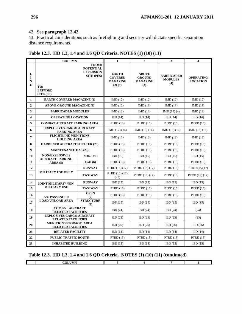
296 AFMAN91-201 12 JANUARY 2011
42. See paragraph 12.42.
43. Practical considerations such as firefighting and security will dictate specific separation
distance requirements.
Table 12.3. HD 1.3, 1.4 and 1.6 QD Criteria. NOTES (1) (10) (11)
COLUMN 1 2 3 4
L
I
N
E
FROM:
POTENTIAL
EXPLOSION
SITE (PES)
TO:
EXPOSED
SITE (ES)
EARTH
COVERED
MAGAZINE
(2) (9)
ABOVE
GROUND
MAGAZINE
(3)
BARRICADED
MODULES
(4)
OPERATING
LOCATION
1 EARTH COVERED MAGAZINE (2) IMD (12) IMD (12) IMD (12) IMD (12)
2 ABOVE GROUND MAGAZINE (3) IMD (12) IMD (13) IMD (13) IMD (13)
3 BARRICADED MODULES IMD (12) IMD (13) IMD (13) (4) IMD (13)
4 OPERATING LOCATION ILD (14) ILD (14) ILD (14) ILD (14)
5 COMBAT AIRCRAFT PARKING AREA PTRD (15) PTRD (15) PTRD (15) PTRD (15)
6 EXPLOSIVES CARGO AIRCRAFT
PARKING AREA IMD (12) (16) IMD (13) (16) IMD (13) (16) IMD (13) (16)
7 FLIGHTLINE MUNITIONS
HOLDING AREA IMD (12) IMD (13) IMD (13) IMD (13)
8 HARDENED AIRCRAFT SHELTER (23) PTRD (15) PTRD (15) PTRD (15) PTRD (15)
9 MAINTENANCE HAS (23) PTRD (15) PTRD (15) PTRD (15) PTRD (15)
10 NON-EXPLOSIVES
AIRCRAFT PARKING
AREA (5)
NON-DoD IBD (15) IBD (15) IBD (15) IBD (15)
11 DoD (6) PTRD (15) PTRD (15) PTRD (15) PTRD (15)
12
MILITARY USE ONLY
RUNWAY PTRD (15) (17) PTRD (15) (17) PTRD (15) PTRD (15)(17)
13 TAXIWAY PTRD (15) (17)
(27) PTRD (15) (17) PTRD (15) PTRD (15) (17)
14 JOINT MILITARY/ NON-
MILITARY USE
RUNWAY IBD (15) IBD (15) IBD (15) IBD (15)
15 TAXIWAY PTRD (15) PTRD (15) PTRD (15) PTRD (15)
16 A/C PASSENGER
LOAD/UNLOAD AREA
OPEN
(7) PTRD (15) PTRD (15) PTRD (15) PTRD (15)
17 STRUCTURE
(8) IBD (15) IBD (15) IBD (15) IBD (15)
18 COMBAT AIRCRAFT
RELATED FACILITIES IBD (24) IBD (24) IBD (24) (24)
19 EXPLOSIVES CARGO AIRCRAFT
RELATED FACILITIES ILD (25) ILD (25) ILD (25) (25)
20 MUNITIONS STORAGE AREA
RELATED FACILITIES ILD (26) ILD (26) ILD (26) ILD (26)
21 RELATED FACILITY ILD (14) ILD (14) ILD (14) ILD (14)
22 PUBLIC TRAFFIC ROUTE PTRD (15) PTRD (15) PTRD (15) PTRD (15)
23 INHABITED BUILDING IBD (15) IBD (15) IBD (15) IBD (15)
Table 12.3. HD 1.3, 1.4 and 1.6 QD Criteria. NOTES (1) (10) (11) (continued)
COLUMN 5 6 7 8
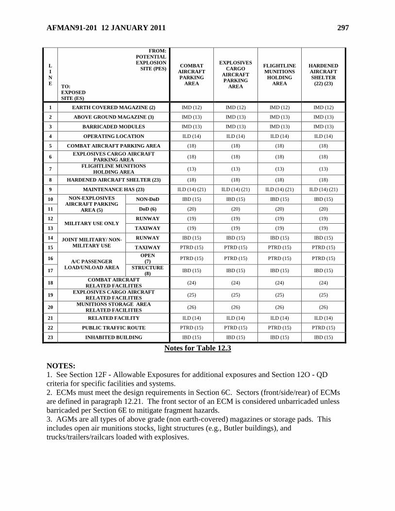
AFMAN91-201 12 JANUARY 2011 297
L
I
N
E
FROM:
POTENTIAL
EXPLOSION
SITE (PES)
TO:
EXPOSED
SITE (ES)
COMBAT
AIRCRAFT
PARKING
AREA
EXPLOSIVES
CARGO
AIRCRAFT
PARKING
AREA
FLIGHTLINE
MUNITIONS
HOLDING
AREA
HARDENED
AIRCRAFT
SHELTER
(22) (23)
1 EARTH COVERED MAGAZINE (2) IMD (12) IMD (12) IMD (12) IMD (12)
2 ABOVE GROUND MAGAZINE (3) IMD (13) IMD (13) IMD (13) IMD (13)
3 BARRICADED MODULES IMD (13) IMD (13) IMD (13) IMD (13)
4 OPERATING LOCATION ILD (14) ILD (14) ILD (14) ILD (14)
5 COMBAT AIRCRAFT PARKING AREA (18) (18) (18) (18)
6 EXPLOSIVES CARGO AIRCRAFT
PARKING AREA (18) (18) (18) (18)
7 FLIGHTLINE MUNITIONS
HOLDING AREA (13) (13) (13) (13)
8 HARDENED AIRCRAFT SHELTER (23) (18) (18) (18) (18)
9 MAINTENANCE HAS (23) ILD (14) (21) ILD (14) (21) ILD (14) (21) ILD (14) (21)
10 NON-EXPLOSIVES
AIRCRAFT PARKING
AREA (5)
NON-DoD IBD (15) IBD (15) IBD (15) IBD (15)
11 DoD (6) (20) (20) (20) (20)
12 MILITARY USE ONLY
RUNWAY (19) (19) (19) (19)
13 TAXIWAY (19) (19) (19) (19)
14 JOINT MILITARY/ NON-
MILITARY USE
RUNWAY IBD (15) IBD (15) IBD (15) IBD (15)
15 TAXIWAY PTRD (15) PTRD (15) PTRD (15) PTRD (15)
16 A/C PASSENGER
LOAD/UNLOAD AREA
OPEN
(7) PTRD (15) PTRD (15) PTRD (15) PTRD (15)
17 STRUCTURE
(8) IBD (15) IBD (15) IBD (15) IBD (15)
18 COMBAT AIRCRAFT
RELATED FACILITIES (24) (24) (24) (24)
19 EXPLOSIVES CARGO AIRCRAFT
RELATED FACILITIES (25) (25) (25) (25)
20 MUNITIONS STORAGE AREA
RELATED FACILITIES (26) (26) (26) (26)
21 RELATED FACILITY ILD (14) ILD (14) ILD (14) ILD (14)
22 PUBLIC TRAFFIC ROUTE PTRD (15) PTRD (15) PTRD (15) PTRD (15)
23 INHABITED BUILDING IBD (15) IBD (15) IBD (15) IBD (15)
Notes for Table 12.3
NOTES:
1. See Section 12F - Allowable Exposures for additional exposures and Section 12O - QD
criteria for specific facilities and systems.
2. ECMs must meet the design requirements in Section 6C. Sectors (front/side/rear) of ECMs
are defined in paragraph 12.21. The front sector of an ECM is considered unbarricaded unless
barricaded per Section 6E to mitigate fragment hazards.
3. AGMs are all types of above grade (non earth-covered) magazines or storage pads. This
includes open air munitions stocks, light structures (e.g., Butler buildings), and
trucks/trailers/railcars loaded with explosives.
298 AFMAN91-201 12 JANUARY 2011
4. The requirements of Section 6D are met (to include limitations on the type of AE which may
be stored in them, and prohibition on the use of heavy structures). If the requirements of Section
6D are not met, use AGM criteria. HD 1.3 is not allowed in modules.
5. Consider parked aeroclub aircraft as non-DoD aircraft for QD purposes; the presence of
aeroclub aircraft does not make an airfield joint-use.
6. MAJCOMs may require greater separation for unique mission or high value aircraft.
7. Use this row for locations in the open where passengers enplane and deplane.
8. Use this row if a structure is included where passengers assemble, such as a passenger
terminal building.
9. ECMs may be used to their physical capacity for HD 1.3 and 1.4 provided they meet
separation requirements for a minimum of 100 lbs of HD 1.1, and provided separations to other
exposures comply with applicable QD criteria.
10. HD 1.4S may be stored (including associated handling) without regard to QD criteria (see
paragraphs 12.29.3 and 2.23.).
11. Magazines storing only HD 1.4 may be located at IMD (per Table 12.13.) to all other
explosives facilities (regardless of HD of NEWQD authorized in these facilities). Because the
HD 1.4 may be destroyed as the result of a mishap involving the assets in these adjacent
explosives facilities, the responsible commander must accept the potential loss of the HD 1.4
stocks and the storage structure. The commander’s risk acceptance must be documented by
letter (i.e., signed by the commander stating he/she understands and accepts the potential loss of
the HD 1.4 stocks and the storage structure in the event of a mishap in an adjacent explosives
facility) and submitted as part of the explosives site plan. A new risk acceptance letter does not
need to be generated when a new adjacent explosives facility is sited, as long as the original
letter documented that other such structures might be added in future.
12. Required IMD separation is as follows:
HD 1.3: See Table 12.12 IMD & ILD Column
HD 1.4: See Table 12.13 ECM IMD Column
HD 1.6: See Table 12.14 IMD & ILD Column
13. Required IMD separation is as follows:
HD 1.3: See Table 12.12 IMD & ILD Column
HD 1.4: See Table 12.13 Applicable AGS IMD Column
HD 1.6: See Table 12.14 IMD & ILD Column
14. Required ILD separation is as follows:
HD 1.3: See Table 12.12 IMD & ILD Column
HD 1.4: See Table 12.13 ILD Column
HD 1.6: See Table 12.14 IMD & ILD Column
15. Required IBD or PTRD separation is as follows:
HD 1.3: See Table 12.12 IBD & PTRD Column
HD 1.4: See Table 12.13 IBD & PTRD Column
HD 1.6: See Table 12.14 IBD & PTRD Column
16. If required by the MAJCOM, for aircraft survivability apply IBD/PTRD separation is as
follows:
HD 1.3: See Table 12.12 IBD & PTRD Column
HD 1.4: See Table 12.13 IBD & PTRD Column
HD 1.6: See Table 12.14 IBD & PTRD Column
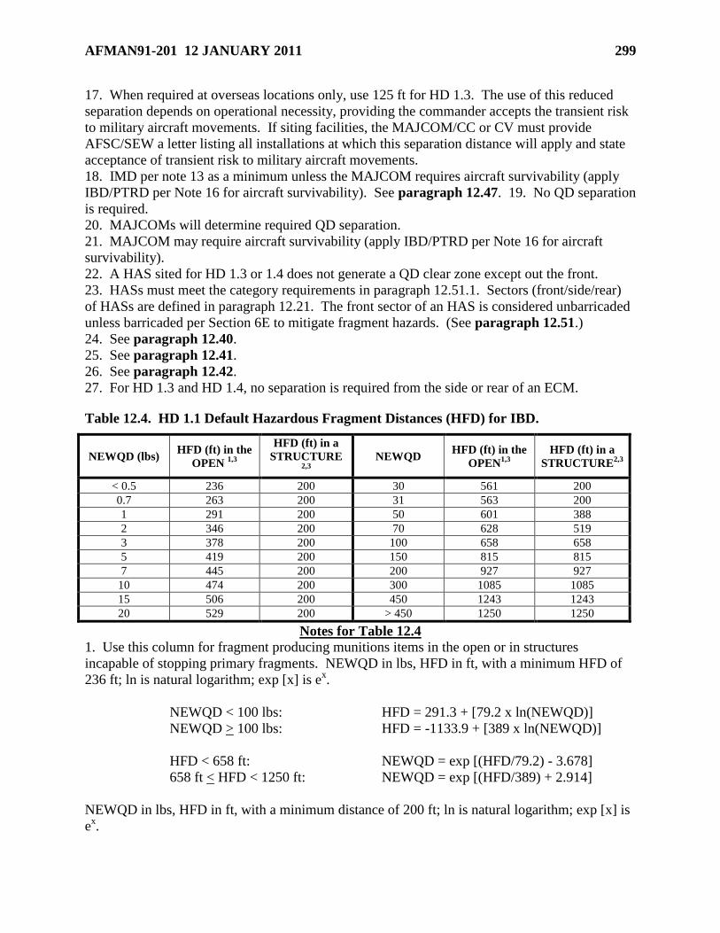
AFMAN91-201 12 JANUARY 2011 299
17. When required at overseas locations only, use 125 ft for HD 1.3. The use of this reduced
separation depends on operational necessity, providing the commander accepts the transient risk
to military aircraft movements. If siting facilities, the MAJCOM/CC or CV must provide
AFSC/SEW a letter listing all installations at which this separation distance will apply and state
acceptance of transient risk to military aircraft movements.
18. IMD per note 13 as a minimum unless the MAJCOM requires aircraft survivability (apply
IBD/PTRD per Note 16 for aircraft survivability). See paragraph 12.47. 19. No QD separation
is required.
20. MAJCOMs will determine required QD separation.
21. MAJCOM may require aircraft survivability (apply IBD/PTRD per Note 16 for aircraft
survivability).
22. A HAS sited for HD 1.3 or 1.4 does not generate a QD clear zone except out the front.
23. HASs must meet the category requirements in paragraph 12.51.1. Sectors (front/side/rear)
of HASs are defined in paragraph 12.21. The front sector of an HAS is considered unbarricaded
unless barricaded per Section 6E to mitigate fragment hazards. (See paragraph 12.51.)
24. See paragraph 12.40.
25. See paragraph 12.41.
26. See paragraph 12.42.
27. For HD 1.3 and HD 1.4, no separation is required from the side or rear of an ECM.
Table 12.4. HD 1.1 Default Hazardous Fragment Distances (HFD) for IBD.
NEWQD (lbs) HFD (ft) in the
OPEN 1,3
HFD (ft) in a
STRUCTURE 2,3
NEWQD HFD (ft) in the
OPEN1,3
HFD (ft) in a
STRUCTURE2,3
< 0.5 236 200 30 561 200
0.7 263 200 31 563 200
1 291 200 50 601 388
2 346 200 70 628 519
3 378 200 100 658 658
5 419 200 150 815 815
7 445 200 200 927 927
10 474 200 300 1085 1085
15 506 200 450 1243 1243
20 529 200 > 450 1250 1250
Notes for Table 12.4
1. Use this column for fragment producing munitions items in the open or in structures
incapable of stopping primary fragments. NEWQD in lbs, HFD in ft, with a minimum HFD of
236 ft; ln is natural logarithm; exp [x] is ex.
NEWQD < 100 lbs: HFD = 291.3 + [79.2 x ln(NEWQD)]
NEWQD > 100 lbs: HFD = -1133.9 + [389 x ln(NEWQD)]
HFD < 658 ft: NEWQD = exp [(HFD/79.2) - 3.678]
658 ft < HFD < 1250 ft: NEWQD = exp [(HFD/389) + 2.914]
NEWQD in lbs, HFD in ft, with a minimum distance of 200 ft; ln is natural logarithm; exp [x] is
ex.
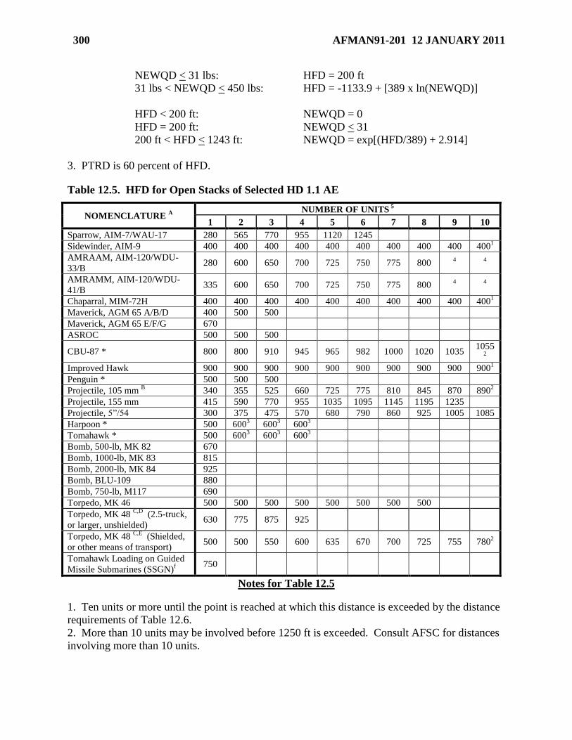
300 AFMAN91-201 12 JANUARY 2011
NEWQD < 31 lbs: HFD = 200 ft
31 lbs < NEWQD < 450 lbs: HFD = -1133.9 + [389 x ln(NEWQD)]
HFD < 200 ft: NEWQD = 0
HFD = 200 ft: NEWQD < 31
200 ft < HFD < 1243 ft: NEWQD = exp[(HFD/389) + 2.914]
3. PTRD is 60 percent of HFD.
Table 12.5. HFD for Open Stacks of Selected HD 1.1 AE
NOMENCLATURE A
NUMBER OF UNITS 5
1 2 3 4 5 6 7 8 9 10
Sparrow, AIM-7/WAU-17 280 565 770 955 1120 1245
Sidewinder, AIM-9 400 400 400 400 400 400 400 400 400 4001
AMRAAM, AIM-120/WDU-
33/B 280 600 650 700 725 750 775 800
4
4
AMRAMM, AIM-120/WDU-
41/B 335 600 650 700 725 750 775 800
4
4
Chaparral, MIM-72H 400 400 400 400 400 400 400 400 400 4001
Maverick, AGM 65 A/B/D 400 500 500
Maverick, AGM 65 E/F/G 670
ASROC 500 500 500
CBU-87 * 800 800 910 945 965 982 1000 1020 1035 1055
2
Improved Hawk 900 900 900 900 900 900 900 900 900 9001
Penguin * 500 500 500
Projectile, 105 mm B 340 355 525 660 725 775 810 845 870 890
2
Projectile, 155 mm 415 590 770 955 1035 1095 1145 1195 1235
Projectile, 5‖/54 300 375 475 570 680 790 860 925 1005 1085
Harpoon * 500 6003 600
3 600
3
Tomahawk * 500 6003 600
3 600
3
Bomb, 500-lb, MK 82 670
Bomb, 1000-lb, MK 83 815
Bomb, 2000-lb, MK 84 925
Bomb, BLU-109 880
Bomb, 750-lb, M117 690
Torpedo, MK 46 500 500 500 500 500 500 500 500
Torpedo, MK 48 C,D
(2.5-truck,
or larger, unshielded) 630 775 875 925
Torpedo, MK 48 C,E
(Shielded,
or other means of transport) 500 500 550 600 635 670 700 725 755 780
2
Tomahawk Loading on Guided
Missile Submarines (SSGN)f
750
Notes for Table 12.5
1. Ten units or more until the point is reached at which this distance is exceeded by the distance
requirements of Table 12.6.
2. More than 10 units may be involved before 1250 ft is exceeded. Consult AFSC for distances
involving more than 10 units.
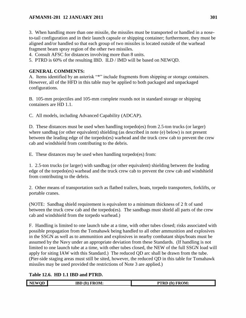
AFMAN91-201 12 JANUARY 2011 301
3. When handling more than one missile, the missiles must be transported or handled in a nose-
to-tail configuration and in their launch capsule or shipping container; furthermore, they must be
aligned and/or handled so that each group of two missiles is located outside of the warhead
fragment beam spray region of the other two missiles.
4. Consult AFSC for distances involving more than 8 units.
5. PTRD is 60% of the resulting IBD. ILD / IMD will be based on NEWQD.
GENERAL COMMENTS:
A. Items identified by an asterisk ―*‖ include fragments from shipping or storage containers.
However, all of the HFD in this table may be applied to both packaged and unpackaged
configurations.
B. 105-mm projectiles and 105-mm complete rounds not in standard storage or shipping
containers are HD 1.1.
C. All models, including Advanced Capability (ADCAP).
D. These distances must be used when handling torpedo(es) from 2.5-ton trucks (or larger)
where sandbag (or other equivalent) shielding (as described in note (e) below) is not present
between the leading edge of the torpedo(es) warhead and the truck crew cab to prevent the crew
cab and windshield from contributing to the debris.
E. These distances may be used when handling torpedo(es) from:
1. 2.5-ton trucks (or larger) with sandbag (or other equivalent) shielding between the leading
edge of the torpedo(es) warhead and the truck crew cab to prevent the crew cab and windshield
from contributing to the debris.
2. Other means of transportation such as flatbed trailers, boats, torpedo transporters, forklifts, or
portable cranes.
(NOTE: Sandbag shield requirement is equivalent to a minimum thickness of 2 ft of sand
between the truck crew cab and the torpedo(es). The sandbags must shield all parts of the crew
cab and windshield from the torpedo warhead.)
F. Handling is limited to one launch tube at a time, with other tubes closed; risks associated with
possible propagation from the Tomahawk being handled to all other ammunition and explosives
in the SSGN as well as to ammunition and explosives in nearby combatant ships/boats must be
assumed by the Navy under an appropriate deviation from these Standards. (If handling is not
limited to one launch tube at a time, with other tubes closed, the NEW of the full SSGN load will
apply for siting IAW with this Standard.) The reduced QD arc shall be drawn from the tube.
(Pier-side staging areas must still be sited, however, the reduced QD in this table for Tomahawk
missiles may be used provided the restrictions of Note 3 are applied.)
Table 12.6. HD 1.1 IBD and PTRD.
NEWQD IBD (ft) FROM: PTRD (ft) FROM:
302 AFMAN91-201 12 JANUARY 2011
(lbs) ECM OTHER
PESs 3
ECM OTHER
PESs 4 FRONT
1 SIDE
1 REAR
2 FRONT
4 SIDE
4 REAR
4
1 500 250 250
NOTE 3
300 150 150
NOTE 4
1.5 500 250 250 300 150 150
2 500 250 250 300 150 150
3 500 250 250 300 150 150
5 500 250 250 300 150 150
7 500 250 250 300 150 150
10 500 250 250 300 150 150
15 500 250 250 300 150 150
20 500 250 250 300 150 150
30 500 250 250 300 150 150
50 500 250 250 300 150 150
70 500 250 250 300 150 150
100 500 250 250 300 150 150
150 500 250 250 300 150 150
200 700 250 250 420 150 150
300 700 250 250 420 150 150
450 700 250 250 420 150 150
500 1,250 1,250 1,250 1,250 750 750 750 750
700 1,250 1,250 1,250 1,250 750 750 750 750
1,000 1,250 1,250 1,250 1,250 750 750 750 750
1,500 1,250 1,250 1,250 1,250 750 750 750 750
2,000 1,250 1,250 1,250 1,250 750 750 750 750
3,000 1,250 1,250 1,250 1,250 750 750 750 750
5,000 1,250 1,250 1,250 1,250 750 750 750 750
7,000 1,250 1,250 1,250 1,250 750 750 750 750
10,000 1,250 1,250 1,250 1,250 750 750 750 750
15,000 1,250 1,250 1,250 1,250 750 750 750 750
20,000 1,250 1,250 1,250 1,250 750 750 750 750
30,000 1,250 1,250 1,250 1,250 750 750 750 750
45,000 1,250 1,250 1,250 1,423 750 750 750 854
50,000 1,289 1,289 1,250 1,474 774 774 750 884
70,000 1,442 1,442 1,250 1,649 865 865 750 989
100,000 1,625 1,625 1,250 1,857 975 975 750 1,114
150,000 2,177 2,177 1,804 2,346 1,306 1,306 1,083 1,408
200,000 2,680 2,680 2,469 2,770 1,608 1,608 1,481 1,662
250,000 3,149 3,149 3,149 3,151 1,889 1,889 1,889 1,891
300,000 3,347 3,347 3,347 3,347 2,008 2,008 2,008 2,008
500,000 3,969 3,969 3,969 3,969 2,381 2,381 2,381 2,381
Notes for Table 12.6
1. For NEWQD < 45,000 lbs, the distance is controlled by fragments. When fragments are
absent or if the HFD is less than the blast hazard range, then the following blast criteria may be
used. (NEWQD in lbs, d in ft)
NEWQD < 45,000 lbs: d = 35NEWQD1/3
45,000 lbs < NEWQD < 100,000 lbs: d = 35NEWQD1/3
100,000 lbs < NEWQD < 250,000 lbs: d = 0.3955NEWQD0.7227
AFMAN91-201 12 JANUARY 2011 303
250,000 lbs < NEWQD: d = 50NEWQD1/3
d < 1,245 ft: NEWQD = d3/42,875
1,245 ft < d < 1,625 ft: NEWQD = d3/42,875
1,625 ft < d < 3,150 ft: NEWQD = 3.60935d1.3837
3,150 ft < d: NEWQD = d3/125,000
2. For NEWQD < 100,000 lbs, the distance is controlled by fragments and debris. When
fragments and debris are absent or the range to a hazardous debris density of 1/600 ft2 is less than
the blast hazard range, then the blast criteria may be used. (NEWQD in lbs, d in ft)
NEWQD < 100,000 lbs: d = 25NEWQD1/3
100,000 lbs < NEWQD < 250,000 lbs: d = 0.004125NEWQD1.0898
250,000 lbs < NEWQD: d = 50NEWQD1/3
d < 1,160 ft: NEWQD = d3/15,625
1,160 ft < d < 3,150 ft: NEWQD = 154.2006d0.91760
3,150 ft < d: NEWQD = d3/125,000
3. For NEWQD < 30,000 lbs, the distance is controlled by fragments and debris. Lesser
distances may be permitted for certain situations (see paragraph 12.23.1). (NEWQD in lbs, d in
ft)
30,000 lbs < NEWQD < 100,000 lbs: d = 40NEWQD1/3
100,000 lbs < NEWQD < 250,000 lbs: d = 2.42NEWQD0.577
250,000 lbs < NEWQD: d = 50NEWQD1/3
1,243 ft < d < 1,857 ft: NEWQD = d3/64,000
1,857 ft < d < 3,150 ft: NEWQD = 0.2162d1.7331
3,150 ft < d: NEWQD = d3/125,000
4. Computed as 60 percent of applicable IBD.
304 AFMAN91-201 12 JANUARY 2011
Table 12.7. HD 1.1 ILD from an ECM.
NEWQD (lbs) BARRICADED ILD (ft) UNBARRICADED ILD (ft)
FRONT1 SIDE
2 REAR
3 FRONT
4 SIDE
5 REAR
6
50 37 26 22 66 59 44
70 41 29 25 74 66 49
100 46 32 28 84 74 56
150 53 37 32 96 85 64
200 58 41 35 105 94 70
300 67 47 40 120 107 80
500 79 56 48 143 127 95
700 89 62 53 160 142 107
1,000 100 70 60 180 160 120
1,500 114 80 69 206 183 137
2,000 126 88 76 227 202 151
3,000 144 101 87 260 231 173
5,000 171 120 103 308 274 205
7,000 191 134 115 344 306 230
10,000 215 151 129 388 345 259
15,000 247 173 148 444 395 296
20,000 271 190 163 489 434 326
30,000 311 218 186 559 497 373
50,000 368 258 221 663 589 442
70,000 412 288 247 742 659 495
100,000 464 325 278 835 743 557
150,000 531 372 319 956 850 653
200,000 585 409 351 1,053 936 746
300,000 669 469 402 1,205 1,071 937
500,000 715 714 714 1,429 1,429 1,429
Notes for Table 12.7
1. NEWQD in lbs, d in ft
NEWQD < 300,000: d = 10 x NEWQD1/3
300,000 lbs < NEWQD < 500,000 lbs:
d = (13.659 – 1.6479 x 10⁻⁵
x NEWQD + 1.4358 x 10
-11 x NEWQD
2) x NEWQD
1/3
d < 669 ft: NEWQD = d3/1000
669 ft < d < 715 ft:
NEWQD = 1.50138 x 10⁸ – 6.73914 x 10
5 x d + 1002.9 x d
2 – 0.4938 x d
3
2. NEWQD in lbs, d in ft
NEWQD < 300,000 lbs: d = 7 x NEWQD1/3
300,000 lbs < NEWQD < 400,000 lbs:
d = (1.0848 + 1.986 x 10⁻⁵
x NEWQD) x NEWQD1/3
NEWQD > 400,000 lbs: d = 9 x NEWQD1/3
d < 469 ft: NEWQD = d3/343
469 ft < d < 663 ft: NEWQD = 57,424 + 515.89 x d

AFMAN91-201 12 JANUARY 2011 305
d > 663 ft: NEWQD = d3/729
3. NEWQD in lbs, d in ft
NEWQD < 300,000 lbs: d = 6 x NEWQD1/3
300,000 lbs < NEWQD < 400,000 lbs:
d = (-3.059 + 3.0228 x 10⁻⁵
x NEWQD) x NEWQD1/3
NEWQD > 400,000 lbs: d = 9 x NEWQD1/3
d < 402 ft: NEWQD = d3/216
402 ft < d < 665 ft: NEWQD = 148,160 + 379.7 x d
d > 665 ft: NEWQD = d3/729
4. NEWQD in lbs, d in ft
NEWQD < 500,000 lbs: d = 18 x NEWQD1/3
d < 1429 ft: NEWQD = d3/5,832
5. NEWQD in lbs, d in ft
NEWQD < 300,000 lbs: d = 16 x NEWQD1/3
300,000 lbs < NEWQD < 400,000 lbs:
d = (9.9683 + 2.0135 x 10⁻⁵
x NEWQD) x NEWQD1/3
NEWQD > 400,000 lbs: d = 18 x NEWQD1/3
d < 1071 ft: NEWQD = d3/4,096
1071 ft < d < 1328 ft: NEWQD = -118,180 + 390.35 x d
d > 1328 ft: NEWQD = d3/5,832
6. NEWQD in lbs, d in ft
NEWQD < 100,000 lbs: d = 12 x NEWQD1/3
100,000 lbs < NEWQD < 300,000 lbs:
d = (11.521 + 1.9918 x 10⁻⁶
x NEWQD + 2.0947 x 10
-11 x NEWQD
2) x NEWQD
1/3
300,000 lbs < NEWQD < 400,000 lbs:
d = (1.9389+ 4.0227 x 10⁻⁵
x NEWQD) x NEWQD1/3
NEWQD > 400,000 lbs: d = 18 x NEWQD1/3
d < 557 ft: NEWQD = d3/1,728
557 ft < d < 938 ft: NEWQD = -193,080+526.83 x d
938 ft < d < 1328 ft: NEWQD = 60,778 + 255.83 x d
d > 1328 ft: NEWQD = d3/5,832
Table 12.8. HD 1.1 ILD other than ECM.
NEWQD
(lbs)
BARRICADED
ILD (ft) 1
UNBARRICADED
ILD (ft) 2
NEWQD
(lbs)
BARRICADED
ILD (ft) 1
UNBARRICADED
ILD (ft) 2
306 AFMAN91-201 12 JANUARY 2011
503 33 66 20,000 244 489
70 37 74 30,000 280 559
100 42 84 50,000 332 663
150 48 96 70,000 371 742
200 53 105 100,000 418 835
300 60 120 150,000 478 956
500 71 143 200,000 526 1,053
700 80 160 300,000 602 1,205
1,000 90 180 500,0004 714 1,429
1,500 103 206 700,0004 799 1,598
2,000 113 227 1,000,0004 900 1,800
3,000 130 260 1,500,0004 1,030 2,060
5,000 154 308 2,000,0004 1,134 2,268
7,000 172 344 3,000,0004 1,298 2,596
10,000 194 388 5,000,0004 1,539 3,078
15,000 222 444
Notes for Table 12.8
1. d in ft, NEWQD in lbs
NEWQD > 50 lbs: d = 9 x NEWQD1/3
d > 33ft: NEWQD = d3/729
d < 33 ft: see note 3
NEWQD < 50 lbs: see note 3
2. d in ft, NEWQD in lbs
NEWQD > 50 lbs: d = 18 x NEWQD1/3
d > 66ft: NEWQD = d3/5,832
d < 66 ft: see note 3
NEWQD < 50 lbs: see note 3
3. For less than 50 lbs, less distance may be used when structures, blast mats, and the like can
completely contain fragments and debris. This table is not applicable when blast, fragments, and
debris are completely confined, as in certain test firing barricades. Note: UFC 3-340-02,
Structures to Resist the Effects of Accidental Explosions, may be used to prove complete
confinement of blast, fragments, and debris. Continue using K18 without a minimum distance
for specific situations having approved guidance such as Reduced MCEs for F-15/F-16 Aircraft
and the 15 Jan 2003 SDW memo.
4. Quantities above 500,000 lbs NEWQD are authorized only for HD 1.1 energetic liquids.
Table 12.9. HD 1.2.1 QD in the Open.
EXPLOSIVE
WEIGHT 1
(lbs)
IBD 2
(ft)
PTRD 3
(ft)
ILD 4
(ft)
EXPLOSIVE
WEIGHT 1
(lbs)
IBD 2
(ft)
PTRD 3
(ft)
ILD 4
(ft)
2 200 200 200 1,500 774 464 278
3 200 200 200 2,000 824 494 296
4 200 200 200 3,000 893 536 321
5 200 200 200 5,000 978 587 352
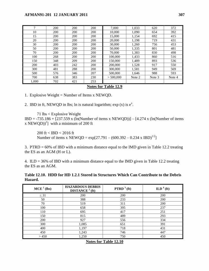
AFMAN91-201 12 JANUARY 2011 307
7 200 200 200 7,000 1,033 620 372
10 200 200 200 10,000 1,090 654 392
15 200 200 200 15,000 1,154 692 415
20 200 200 200 20,000 1,198 719 431
30 200 200 200 30,000 1,260 756 453
50 200 200 200 50,000 1,335 801 481
70 200 200 200 70,000 1,383 830 498
100 268 200 200 100,000 1,433 860 516
150 348 209 200 150,000 1,489 893 536
200 403 242 200 200,000 1,528 917 550
300 481 288 200 300,000 1,581 949 569
500 576 346 207 500,000 1,646 988 593
700 638 383 230 > 500,000 Note 2 Note 3 Note 4
1,000 702 421 253
Notes for Table 12.9
1. Explosive Weight = Number of Items x NEWQD.
2. IBD in ft, NEWQD in lbs; ln is natural logarithm; exp (x) is ex.
71 lbs < Explosive Weight
IBD = -735.186 + [237.559 x (ln(Number of items x NEWQD))] – [4.274 x (ln(Number of items
x NEWQD))2] with a minimum of 200 ft
200 ft < IBD < 2016 ft
Number of items x NEWQD = exp[27.791 – (600.392 – 0.234 x IBD)1/2
]
3. PTRD = 60% of IBD with a minimum distance equal to the IMD given in Table 12.2 treating
the ES as an AGM (H or L).
4. ILD = 36% of IBD with a minimum distance equal to the IMD given in Table 12.2 treating
the ES as an AGM.
Table 12.10. HDD for HD 1.2.1 Stored in Structures Which Can Contribute to the Debris
Hazard.
MCE 1 (lbs)
HAZARDOUS DEBRIS
DISTANCE 2 (ft)
PTRD 3 (ft) ILD
4 (ft)
< 31 200 200 200
50 388 233 200
70 519 311 200
100 658 395 237
110 695 417 251
150 815 489 293
200 927 556 334
300 1,085 651 391
400 1,197 718 431
450 1,243 746 447
> 450 1,250 750 450
Notes for Table 12.10
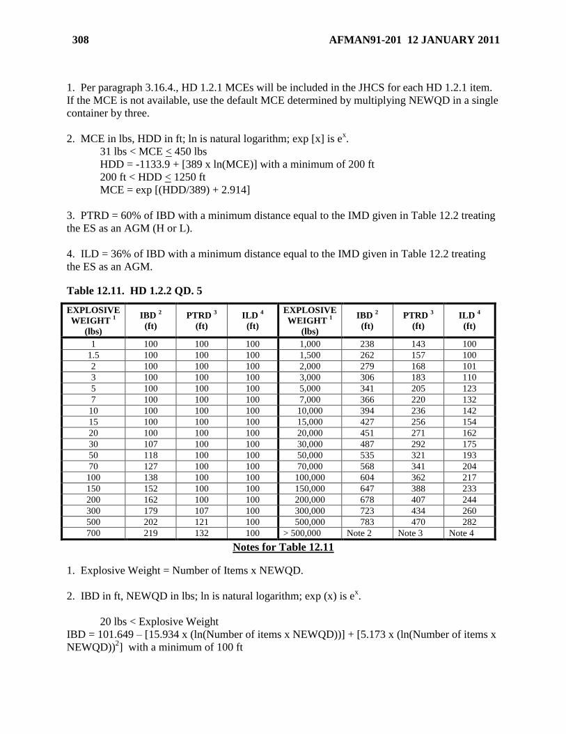
308 AFMAN91-201 12 JANUARY 2011
1. Per paragraph 3.16.4., HD 1.2.1 MCEs will be included in the JHCS for each HD 1.2.1 item.
If the MCE is not available, use the default MCE determined by multiplying NEWQD in a single
container by three.
2. MCE in lbs, HDD in ft; ln is natural logarithm; exp [x] is ex.
31 lbs < MCE < 450 lbs
HDD = -1133.9 + [389 x ln(MCE)] with a minimum of 200 ft
200 ft < HDD < 1250 ft
MCE = exp [(HDD/389) + 2.914]
3. PTRD = 60% of IBD with a minimum distance equal to the IMD given in Table 12.2 treating
the ES as an AGM (H or L).
4. ILD = 36% of IBD with a minimum distance equal to the IMD given in Table 12.2 treating
the ES as an AGM.
Table 12.11. HD 1.2.2 QD. 5
EXPLOSIVE
WEIGHT 1
(lbs)
IBD 2
(ft)
PTRD 3
(ft)
ILD 4
(ft)
EXPLOSIVE
WEIGHT 1
(lbs)
IBD 2
(ft)
PTRD 3
(ft)
ILD 4
(ft)
1 100 100 100 1,000 238 143 100
1.5 100 100 100 1,500 262 157 100
2 100 100 100 2,000 279 168 101
3 100 100 100 3,000 306 183 110
5 100 100 100 5,000 341 205 123
7 100 100 100 7,000 366 220 132
10 100 100 100 10,000 394 236 142
15 100 100 100 15,000 427 256 154
20 100 100 100 20,000 451 271 162
30 107 100 100 30,000 487 292 175
50 118 100 100 50,000 535 321 193
70 127 100 100 70,000 568 341 204
100 138 100 100 100,000 604 362 217
150 152 100 100 150,000 647 388 233
200 162 100 100 200,000 678 407 244
300 179 107 100 300,000 723 434 260
500 202 121 100 500,000 783 470 282
700 219 132 100 > 500,000 Note 2 Note 3 Note 4
Notes for Table 12.11
1. Explosive Weight = Number of Items x NEWQD.
2. IBD in ft, NEWQD in lbs; ln is natural logarithm; exp (x) is ex.
20 lbs < Explosive Weight
IBD = 101.649 – [15.934 x (ln(Number of items x NEWQD))] + [5.173 x (ln(Number of items x
NEWQD))2] with a minimum of 100 ft
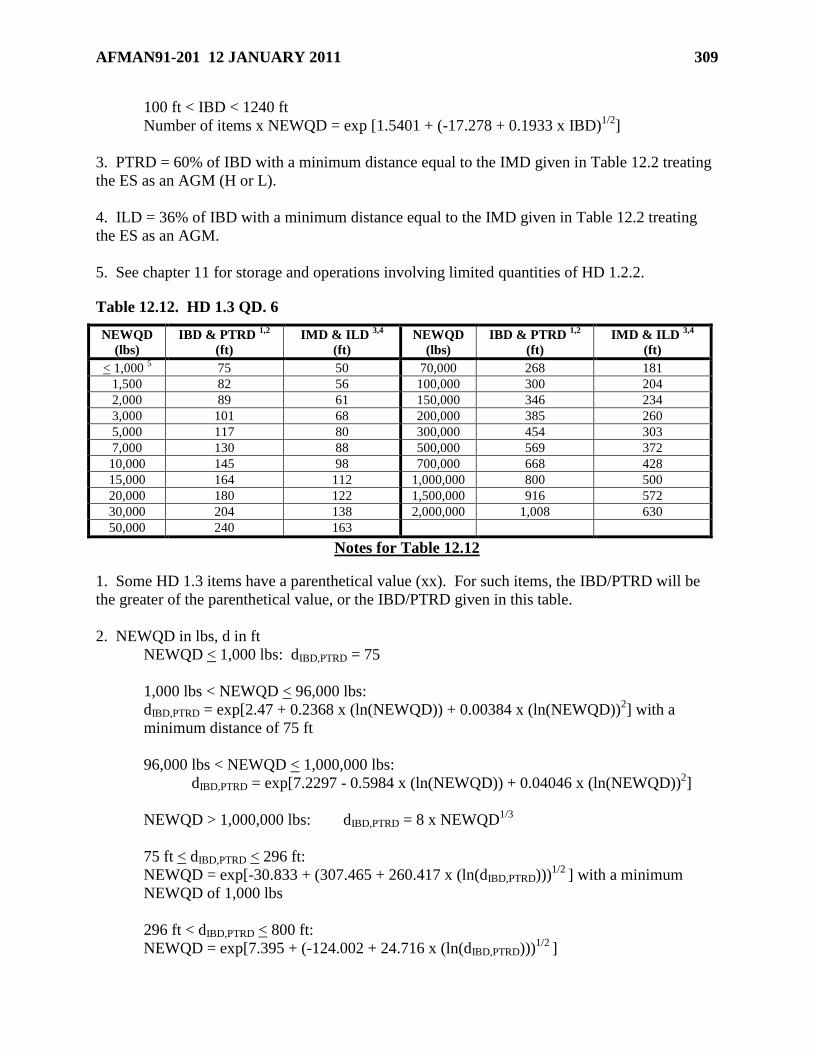
AFMAN91-201 12 JANUARY 2011 309
100 ft < IBD < 1240 ft
Number of items x NEWQD = exp [1.5401 + (-17.278 + 0.1933 x IBD)1/2
]
3. PTRD = 60% of IBD with a minimum distance equal to the IMD given in Table 12.2 treating
the ES as an AGM (H or L).
4. ILD = 36% of IBD with a minimum distance equal to the IMD given in Table 12.2 treating
the ES as an AGM.
5. See chapter 11 for storage and operations involving limited quantities of HD 1.2.2.
Table 12.12. HD 1.3 QD. 6
NEWQD
(lbs)
IBD & PTRD 1,2
(ft)
IMD & ILD 3,4
(ft)
NEWQD
(lbs)
IBD & PTRD 1,2
(ft)
IMD & ILD 3,4
(ft)
< 1,000 5 75 50 70,000 268 181
1,500 82 56 100,000 300 204
2,000 89 61 150,000 346 234
3,000 101 68 200,000 385 260
5,000 117 80 300,000 454 303
7,000 130 88 500,000 569 372
10,000 145 98 700,000 668 428
15,000 164 112 1,000,000 800 500
20,000 180 122 1,500,000 916 572
30,000 204 138 2,000,000 1,008 630
50,000 240 163
Notes for Table 12.12
1. Some HD 1.3 items have a parenthetical value (xx). For such items, the IBD/PTRD will be
the greater of the parenthetical value, or the IBD/PTRD given in this table.
2. NEWQD in lbs, d in ft
NEWQD < 1,000 lbs: dIBD,PTRD = 75
1,000 lbs < NEWQD < 96,000 lbs:
dIBD,PTRD = exp[2.47 + 0.2368 x (ln(NEWQD)) + 0.00384 x (ln(NEWQD))2] with a
minimum distance of 75 ft
96,000 lbs < NEWQD < 1,000,000 lbs:
dIBD,PTRD = exp[7.2297 - 0.5984 x (ln(NEWQD)) + 0.04046 x (ln(NEWQD))2]
NEWQD > 1,000,000 lbs: dIBD,PTRD = 8 x NEWQD1/3
75 ft < dIBD,PTRD < 296 ft:
NEWQD = exp[-30.833 + (307.465 + 260.417 x (ln(dIBD,PTRD)))1/2
] with a minimum
NEWQD of 1,000 lbs
296 ft < dIBD,PTRD < 800 ft:
NEWQD = exp[7.395 + (-124.002 + 24.716 x (ln(dIBD,PTRD)))1/2
]
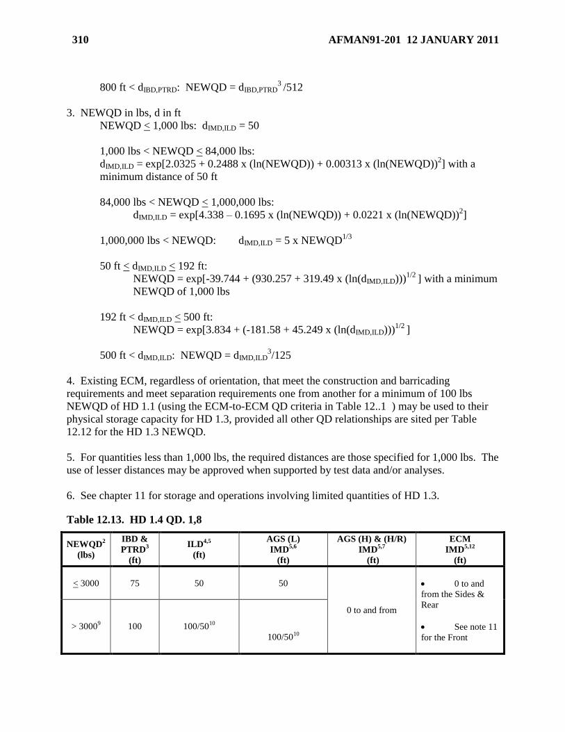
310 AFMAN91-201 12 JANUARY 2011
800 ft < dIBD,PTRD: NEWQD = dIBD,PTRD3
/512
3. NEWQD in lbs, d in ft
NEWQD < 1,000 lbs: dIMD,ILD = 50
1,000 lbs < NEWQD < 84,000 lbs:
dIMD,ILD = exp[2.0325 + 0.2488 x (ln(NEWQD)) + 0.00313 x (ln(NEWQD))2] with a
minimum distance of 50 ft
84,000 lbs < NEWQD < 1,000,000 lbs:
dIMD,ILD = exp[4.338 – 0.1695 x (ln(NEWQD)) + 0.0221 x (ln(NEWQD))2]
1,000,000 lbs < NEWQD: dIMD,ILD = 5 x NEWQD1/3
50 ft < dIMD,ILD < 192 ft:
NEWQD = exp[-39.744 + (930.257 + 319.49 x (ln(dIMD,ILD)))1/2
] with a minimum
NEWQD of 1,000 lbs
192 ft < dIMD,ILD < 500 ft:
NEWQD = exp[3.834 + (-181.58 + 45.249 x (ln(dIMD,ILD)))1/2
]
500 ft < dIMD,ILD: NEWQD = dIMD,ILD3/125
4. Existing ECM, regardless of orientation, that meet the construction and barricading
requirements and meet separation requirements one from another for a minimum of 100 lbs
NEWQD of HD 1.1 (using the ECM-to-ECM QD criteria in Table 12..1 ) may be used to their
physical storage capacity for HD 1.3, provided all other QD relationships are sited per Table
12.12 for the HD 1.3 NEWQD.
5. For quantities less than 1,000 lbs, the required distances are those specified for 1,000 lbs. The
use of lesser distances may be approved when supported by test data and/or analyses.
6. See chapter 11 for storage and operations involving limited quantities of HD 1.3.
Table 12.13. HD 1.4 QD. 1,8
NEWQD2
(lbs)
IBD &
PTRD3
(ft)
ILD4,5
(ft)
AGS (L)
IMD5,6
(ft)
AGS (H) & (H/R)
IMD5,7
(ft)
ECM
IMD5,12
(ft)
< 3000
75 50
50
0 to and from
0 to and
from the Sides &
Rear
See note 11
for the Front
> 30009 100 100/50
10
100/5010
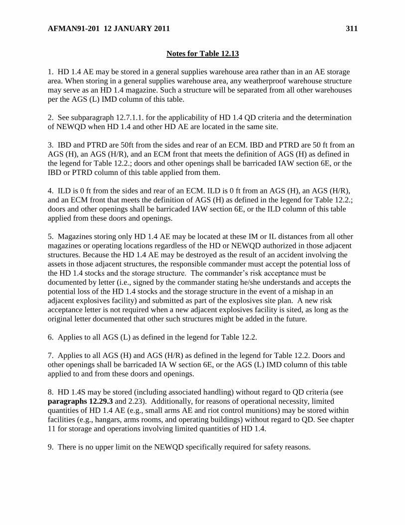
AFMAN91-201 12 JANUARY 2011 311
Notes for Table 12.13
1. HD 1.4 AE may be stored in a general supplies warehouse area rather than in an AE storage
area. When storing in a general supplies warehouse area, any weatherproof warehouse structure
may serve as an HD 1.4 magazine. Such a structure will be separated from all other warehouses
per the AGS (L) IMD column of this table.
2. See subparagraph 12.7.1.1. for the applicability of HD 1.4 QD criteria and the determination
of NEWQD when HD 1.4 and other HD AE are located in the same site.
3. IBD and PTRD are 50ft from the sides and rear of an ECM. IBD and PTRD are 50 ft from an
AGS (H), an AGS (H/R), and an ECM front that meets the definition of AGS (H) as defined in
the legend for Table 12.2.; doors and other openings shall be barricaded IAW section 6E, or the
IBD or PTRD column of this table applied from them.
4. ILD is 0 ft from the sides and rear of an ECM. ILD is 0 ft from an AGS (H), an AGS (H/R),
and an ECM front that meets the definition of AGS (H) as defined in the legend for Table 12.2.;
doors and other openings shall be barricaded IAW section 6E, or the ILD column of this table
applied from these doors and openings.
5. Magazines storing only HD 1.4 AE may be located at these IM or IL distances from all other
magazines or operating locations regardless of the HD or NEWQD authorized in those adjacent
structures. Because the HD 1.4 AE may be destroyed as the result of an accident involving the
assets in those adjacent structures, the responsible commander must accept the potential loss of
the HD 1.4 stocks and the storage structure. The commander’s risk acceptance must be
documented by letter (i.e., signed by the commander stating he/she understands and accepts the
potential loss of the HD 1.4 stocks and the storage structure in the event of a mishap in an
adjacent explosives facility) and submitted as part of the explosives site plan. A new risk
acceptance letter is not required when a new adjacent explosives facility is sited, as long as the
original letter documented that other such structures might be added in the future.
6. Applies to all AGS (L) as defined in the legend for Table 12.2.
7. Applies to all AGS (H) and AGS (H/R) as defined in the legend for Table 12.2. Doors and
other openings shall be barricaded IA W section 6E, or the AGS (L) IMD column of this table
applied to and from these doors and openings.
8. HD 1.4S may be stored (including associated handling) without regard to QD criteria (see
paragraphs 12.29.3 and 2.23). Additionally, for reasons of operational necessity, limited
quantities of HD 1.4 AE (e.g., small arms AE and riot control munitions) may be stored within
facilities (e.g., hangars, arms rooms, and operating buildings) without regard to QD. See chapter
11 for storage and operations involving limited quantities of HD 1.4.
9. There is no upper limit on the NEWQD specifically required for safety reasons.
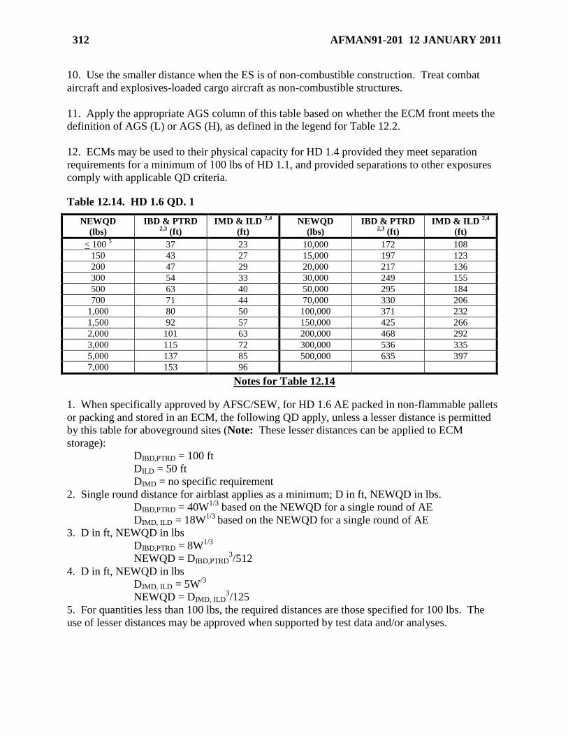
312 AFMAN91-201 12 JANUARY 2011
10. Use the smaller distance when the ES is of non-combustible construction. Treat combat
aircraft and explosives-loaded cargo aircraft as non-combustible structures.
11. Apply the appropriate AGS column of this table based on whether the ECM front meets the
definition of AGS (L) or AGS (H), as defined in the legend for Table 12.2.
12. ECMs may be used to their physical capacity for HD 1.4 provided they meet separation
requirements for a minimum of 100 lbs of HD 1.1, and provided separations to other exposures
comply with applicable QD criteria.
Table 12.14. HD 1.6 QD. 1
NEWQD
(lbs)
IBD & PTRD 2,3
(ft)
IMD & ILD 2,4
(ft)
NEWQD
(lbs)
IBD & PTRD 2,3
(ft)
IMD & ILD 2,4
(ft)
< 100 5 37 23 10,000 172 108
150 43 27 15,000 197 123
200 47 29 20,000 217 136
300 54 33 30,000 249 155
500 63 40 50,000 295 184
700 71 44 70,000 330 206
1,000 80 50 100,000 371 232
1,500 92 57 150,000 425 266
2,000 101 63 200,000 468 292
3,000 115 72 300,000 536 335
5,000 137 85 500,000 635 397
7,000 153 96
Notes for Table 12.14
1. When specifically approved by AFSC/SEW, for HD 1.6 AE packed in non-flammable pallets
or packing and stored in an ECM, the following QD apply, unless a lesser distance is permitted
by this table for aboveground sites (Note: These lesser distances can be applied to ECM
storage):
DIBD,PTRD = 100 ft
DILD = 50 ft
DIMD = no specific requirement
2. Single round distance for airblast applies as a minimum; D in ft, NEWQD in lbs.
DIBD,PTRD = 40W1/3
based on the NEWQD for a single round of AE
DIMD, ILD = 18W1/3
based on the NEWQD for a single round of AE
3. D in ft, NEWQD in lbs
DIBD,PTRD = 8W1/3
NEWQD = DIBD,PTRD3/512
4. D in ft, NEWQD in lbs
DIMD, ILD = 5W/3
NEWQD = DIMD, ILD3/125
5. For quantities less than 100 lbs, the required distances are those specified for 100 lbs. The
use of lesser distances may be approved when supported by test data and/or analyses.
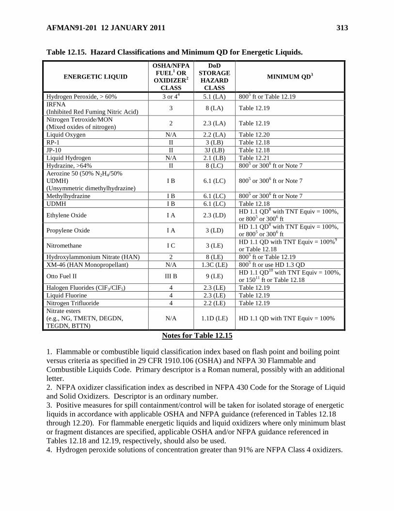
AFMAN91-201 12 JANUARY 2011 313
Table 12.15. Hazard Classifications and Minimum QD for Energetic Liquids.
ENERGETIC LIQUID
OSHA/NFPA
FUEL1 OR
OXIDIZER2
CLASS
DoD
STORAGE
HAZARD
CLASS
MINIMUM QD3
Hydrogen Peroxide, > 60% 3 or 44 5.1 (LA) 800
5 ft or Table 12.19
IRFNA
(Inhibited Red Fuming Nitric Acid) 3 8 (LA) Table 12.19
Nitrogen Tetroxide/MON
(Mixed oxides of nitrogen) 2 2.3 (LA) Table 12.19
Liquid Oxygen N/A 2.2 (LA) Table 12.20
RP-1 II 3 (LB) Table 12.18
JP-10 II 3J (LB) Table 12.18
Liquid Hydrogen N/A 2.1 (LB) Table 12.21
Hydrazine, >64% II 8 (LC) 8005 or 300
6 ft or Note 7
Aerozine 50 (50% N2H4/50%
UDMH)
(Unsymmetric dimethylhydrazine)
I B 6.1 (LC) 8005 or 300
6 ft or Note 7
Methylhydrazine I B 6.1 (LC) 8005 or 300
6 ft or Note 7
UDMH I B 6.1 (LC) Table 12.18
Ethylene Oxide I A 2.3 (LD) HD 1.1 QD
8 with TNT Equiv = 100%,
or 8005 or 300
6 ft
Propylene Oxide I A 3 (LD) HD 1.1 QD
8 with TNT Equiv = 100%,
or 8005 or 300
6 ft
Nitromethane I C 3 (LE) HD 1.1 QD with TNT Equiv = 100%
9
or Table 12.18
Hydroxylammonium Nitrate (HAN) 2 8 (LE) 8005 ft or Table 12.19
XM-46 (HAN Monopropellant) N/A 1.3C (LE) 8005 ft or use HD 1.3 QD
Otto Fuel II III B 9 (LE) HD 1.1 QD
10 with TNT Equiv = 100%,
or 15011
ft or Table 12.18
Halogen Fluorides (ClF3/ClF5) 4 2.3 (LE) Table 12.19
Liquid Fluorine 4 2.3 (LE) Table 12.19
Nitrogen Trifluoride 4 2.2 (LE) Table 12.19
Nitrate esters
(e.g., NG, TMETN, DEGDN,
TEGDN, BTTN)
N/A 1.1D (LE) HD 1.1 QD with TNT Equiv = 100%
Notes for Table 12.15
1. Flammable or combustible liquid classification index based on flash point and boiling point
versus criteria as specified in 29 CFR 1910.106 (OSHA) and NFPA 30 Flammable and
Combustible Liquids Code. Primary descriptor is a Roman numeral, possibly with an additional
letter.
2. NFPA oxidizer classification index as described in NFPA 430 Code for the Storage of Liquid
and Solid Oxidizers. Descriptor is an ordinary number.
3. Positive measures for spill containment/control will be taken for isolated storage of energetic
liquids in accordance with applicable OSHA and NFPA guidance (referenced in Tables 12.18
through 12.20). For flammable energetic liquids and liquid oxidizers where only minimum blast
or fragment distances are specified, applicable OSHA and/or NFPA guidance referenced in
Tables 12.18 and 12.19, respectively, should also be used.
4. Hydrogen peroxide solutions of concentration greater than 91% are NFPA Class 4 oxidizers.
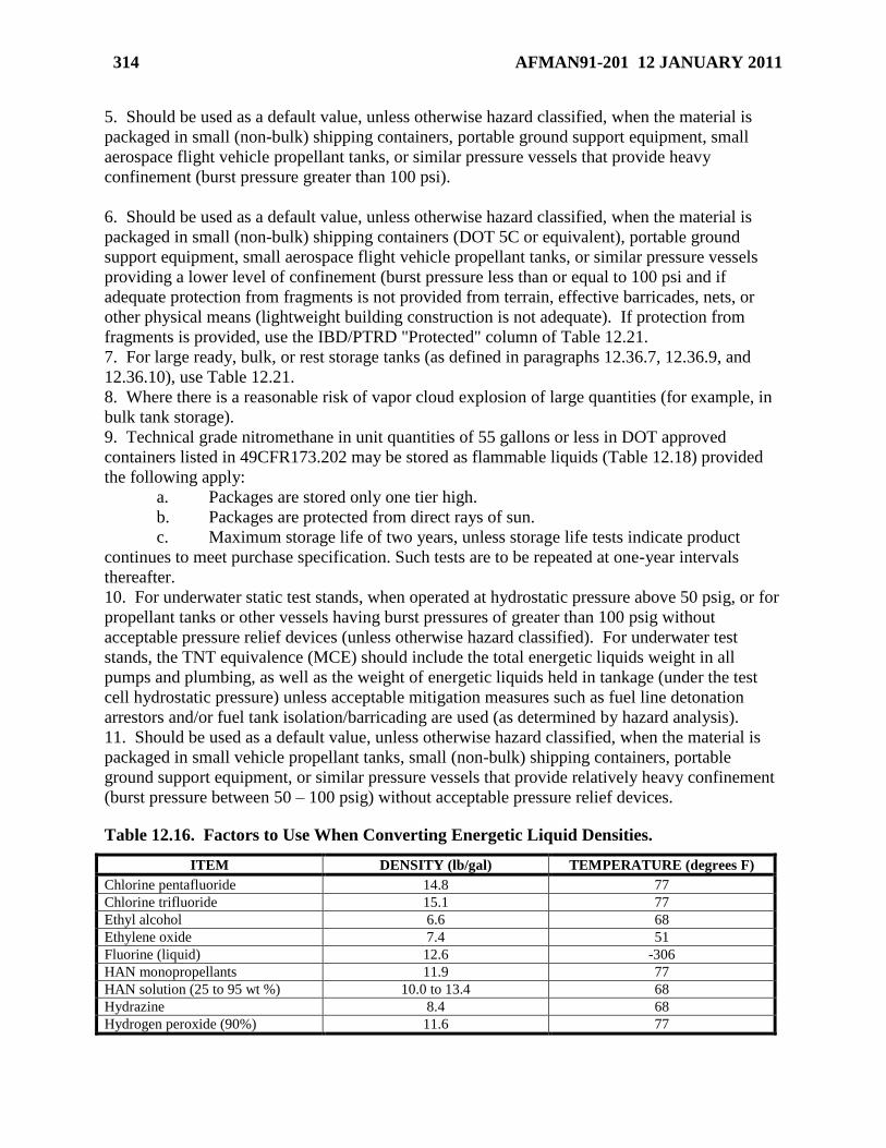
314 AFMAN91-201 12 JANUARY 2011
5. Should be used as a default value, unless otherwise hazard classified, when the material is
packaged in small (non-bulk) shipping containers, portable ground support equipment, small
aerospace flight vehicle propellant tanks, or similar pressure vessels that provide heavy
confinement (burst pressure greater than 100 psi).
6. Should be used as a default value, unless otherwise hazard classified, when the material is
packaged in small (non-bulk) shipping containers (DOT 5C or equivalent), portable ground
support equipment, small aerospace flight vehicle propellant tanks, or similar pressure vessels
providing a lower level of confinement (burst pressure less than or equal to 100 psi and if
adequate protection from fragments is not provided from terrain, effective barricades, nets, or
other physical means (lightweight building construction is not adequate). If protection from
fragments is provided, use the IBD/PTRD "Protected" column of Table 12.21.
7. For large ready, bulk, or rest storage tanks (as defined in paragraphs 12.36.7, 12.36.9, and
12.36.10), use Table 12.21.
8. Where there is a reasonable risk of vapor cloud explosion of large quantities (for example, in
bulk tank storage).
9. Technical grade nitromethane in unit quantities of 55 gallons or less in DOT approved
containers listed in 49CFR173.202 may be stored as flammable liquids (Table 12.18) provided
the following apply:
a. Packages are stored only one tier high.
b. Packages are protected from direct rays of sun.
c. Maximum storage life of two years, unless storage life tests indicate product
continues to meet purchase specification. Such tests are to be repeated at one-year intervals
thereafter.
10. For underwater static test stands, when operated at hydrostatic pressure above 50 psig, or for
propellant tanks or other vessels having burst pressures of greater than 100 psig without
acceptable pressure relief devices (unless otherwise hazard classified). For underwater test
stands, the TNT equivalence (MCE) should include the total energetic liquids weight in all
pumps and plumbing, as well as the weight of energetic liquids held in tankage (under the test
cell hydrostatic pressure) unless acceptable mitigation measures such as fuel line detonation
arrestors and/or fuel tank isolation/barricading are used (as determined by hazard analysis).
11. Should be used as a default value, unless otherwise hazard classified, when the material is
packaged in small vehicle propellant tanks, small (non-bulk) shipping containers, portable
ground support equipment, or similar pressure vessels that provide relatively heavy confinement
(burst pressure between 50 – 100 psig) without acceptable pressure relief devices.
Table 12.16. Factors to Use When Converting Energetic Liquid Densities.
ITEM DENSITY (lb/gal) TEMPERATURE (degrees F)
Chlorine pentafluoride 14.8 77
Chlorine trifluoride 15.1 77
Ethyl alcohol 6.6 68
Ethylene oxide 7.4 51
Fluorine (liquid) 12.6 -306
HAN monopropellants 11.9 77
HAN solution (25 to 95 wt %) 10.0 to 13.4 68
Hydrazine 8.4 68
Hydrogen peroxide (90%) 11.6 77
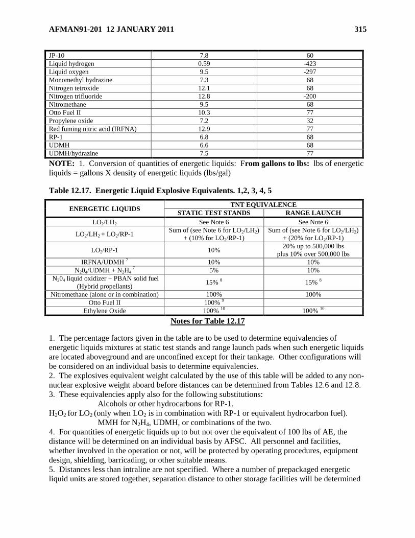
AFMAN91-201 12 JANUARY 2011 315
JP-10 7.8 60
Liquid hydrogen 0.59 -423
Liquid oxygen 9.5 -297
Monomethyl hydrazine 7.3 68
Nitrogen tetroxide 12.1 68
Nitrogen trifluoride 12.8 -200
Nitromethane 9.5 68
Otto Fuel II 10.3 77
Propylene oxide 7.2 32
Red fuming nitric acid (IRFNA) 12.9 77
RP-1 6.8 68
UDMH 6.6 68
UDMH/hydrazine 7.5 77
NOTE: 1. Conversion of quantities of energetic liquids: From gallons to lbs: lbs of energetic
liquids = gallons X density of energetic liquids (lbs/gal)
Table 12.17. Energetic Liquid Explosive Equivalents. 1,2, 3, 4, 5
ENERGETIC LIQUIDS TNT EQUIVALENCE
STATIC TEST STANDS RANGE LAUNCH
LO2/LH2 See Note 6 See Note 6
LO2/LH2 + LO2/RP-1 Sum of (see Note 6 for LO2/LH2)
+ (10% for LO2/RP-1)
Sum of (see Note 6 for LO2/LH2)
+ (20% for LO2/RP-1)
LO2/RP-1 10% 20% up to 500,000 lbs
plus 10% over 500,000 lbs
IRFNA/UDMH 7 10% 10%
N204/UDMH + N2H4 7 5% 10%
N204 liquid oxidizer + PBAN solid fuel
(Hybrid propellants) 15%
8 15%
8
Nitromethane (alone or in combination) 100% 100%
Otto Fuel II 100% 9
Ethylene Oxide 100% 10
100% 10
Notes for Table 12.17
1. The percentage factors given in the table are to be used to determine equivalencies of
energetic liquids mixtures at static test stands and range launch pads when such energetic liquids
are located aboveground and are unconfined except for their tankage. Other configurations will
be considered on an individual basis to determine equivalencies.
2. The explosives equivalent weight calculated by the use of this table will be added to any non-
nuclear explosive weight aboard before distances can be determined from Tables 12.6 and 12.8.
3. These equivalencies apply also for the following substitutions:
Alcohols or other hydrocarbons for RP-1.
H2O2 for LO2 (only when LO2 is in combination with RP-1 or equivalent hydrocarbon fuel).
MMH for N2H4, UDMH, or combinations of the two.
4. For quantities of energetic liquids up to but not over the equivalent of 100 lbs of AE, the
distance will be determined on an individual basis by AFSC. All personnel and facilities,
whether involved in the operation or not, will be protected by operating procedures, equipment
design, shielding, barricading, or other suitable means.
5. Distances less than intraline are not specified. Where a number of prepackaged energetic
liquid units are stored together, separation distance to other storage facilities will be determined
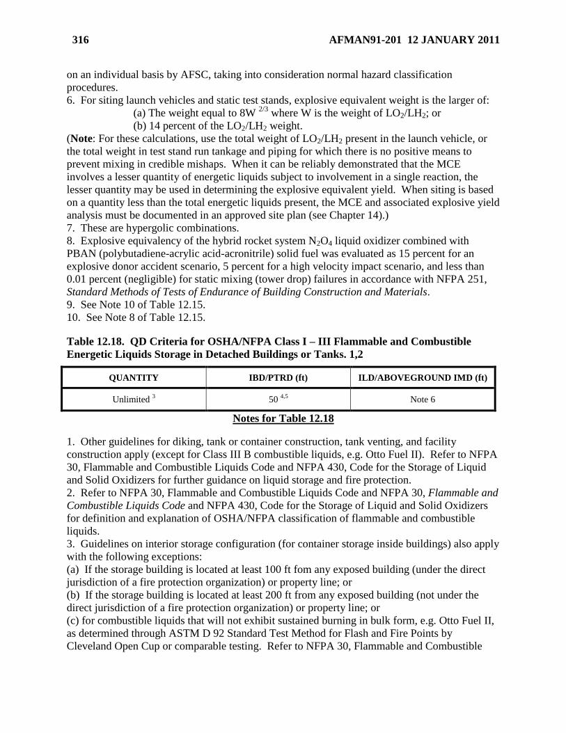
316 AFMAN91-201 12 JANUARY 2011
on an individual basis by AFSC, taking into consideration normal hazard classification
procedures.
6. For siting launch vehicles and static test stands, explosive equivalent weight is the larger of:
(a) The weight equal to 8W 2/3
where W is the weight of LO2/LH2; or
(b) 14 percent of the LO2/LH2 weight.
(Note: For these calculations, use the total weight of LO2/LH2 present in the launch vehicle, or
the total weight in test stand run tankage and piping for which there is no positive means to
prevent mixing in credible mishaps. When it can be reliably demonstrated that the MCE
involves a lesser quantity of energetic liquids subject to involvement in a single reaction, the
lesser quantity may be used in determining the explosive equivalent yield. When siting is based
on a quantity less than the total energetic liquids present, the MCE and associated explosive yield
analysis must be documented in an approved site plan (see Chapter 14).)
7. These are hypergolic combinations.
8. Explosive equivalency of the hybrid rocket system N2O4 liquid oxidizer combined with
PBAN (polybutadiene-acrylic acid-acronitrile) solid fuel was evaluated as 15 percent for an
explosive donor accident scenario, 5 percent for a high velocity impact scenario, and less than
0.01 percent (negligible) for static mixing (tower drop) failures in accordance with NFPA 251,
Standard Methods of Tests of Endurance of Building Construction and Materials.
9. See Note 10 of Table 12.15.
10. See Note 8 of Table 12.15.
Table 12.18. QD Criteria for OSHA/NFPA Class I – III Flammable and Combustible
Energetic Liquids Storage in Detached Buildings or Tanks. 1,2
QUANTITY IBD/PTRD (ft) ILD/ABOVEGROUND IMD (ft)
Unlimited 3 50
4,5 Note 6
Notes for Table 12.18
1. Other guidelines for diking, tank or container construction, tank venting, and facility
construction apply (except for Class III B combustible liquids, e.g. Otto Fuel II). Refer to NFPA
30, Flammable and Combustible Liquids Code and NFPA 430, Code for the Storage of Liquid
and Solid Oxidizers for further guidance on liquid storage and fire protection.
2. Refer to NFPA 30, Flammable and Combustible Liquids Code and NFPA 30, Flammable and
Combustible Liquids Code and NFPA 430, Code for the Storage of Liquid and Solid Oxidizers
for definition and explanation of OSHA/NFPA classification of flammable and combustible
liquids.
3. Guidelines on interior storage configuration (for container storage inside buildings) also apply
with the following exceptions:
(a) If the storage building is located at least 100 ft fom any exposed building (under the direct
jurisdiction of a fire protection organization) or property line; or
(b) If the storage building is located at least 200 ft from any exposed building (not under the
direct jurisdiction of a fire protection organization) or property line; or
(c) for combustible liquids that will not exhibit sustained burning in bulk form, e.g. Otto Fuel II,
as determined through ASTM D 92 Standard Test Method for Flash and Fire Points by
Cleveland Open Cup or comparable testing. Refer to NFPA 30, Flammable and Combustible
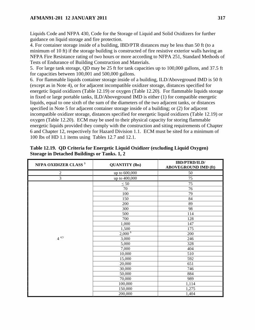
AFMAN91-201 12 JANUARY 2011 317
Liquids Code and NFPA 430, Code for the Storage of Liquid and Solid Oxidizers for further
guidance on liquid storage and fire protection.
4. For container storage inside of a building, IBD/PTR distances may be less than 50 ft (to a
minimum of 10 ft) if the storage building is constructed of fire resistive exterior walls having an
NFPA Fire Resistance rating of two hours or more according to NFPA 251, Standard Methods of
Tests of Endurance of Building Construction and Materials.
5. For large tank storage, QD may be 25 ft for tank capacities up to 100,000 gallons, and 37.5 ft
for capacities between 100,001 and 500,000 gallons.
6. For flammable liquids container storage inside of a building, ILD/Aboveground IMD is 50 ft
(except as in Note 4), or for adjacent incompatible oxidizer storage, distances specified for
energetic liquid oxidizers (Table 12.19) or oxygen (Table 12.20). For flammable liquids storage
in fixed or large portable tanks, ILD/Aboveground IMD is either (1) for compatible energetic
liquids, equal to one sixth of the sum of the diameters of the two adjacent tanks, or distances
specified in Note 5 for adjacent container storage inside of a building; or (2) for adjacent
incompatible oxidizer storage, distances specified for energetic liquid oxidizers (Table 12.19) or
oxygen (Table 12.20). ECM may be used to their physical capacity for storing flammable
energetic liquids provided they comply with the construction and siting requirements of Chapter
6 and Chapter 12, respectively for Hazard Division 1.1. ECM must be sited for a minimum of
100 lbs of HD 1.1 items using Tables 12.7 and 12.1.
Table 12.19. QD Criteria for Energetic Liquid Oxidizer (excluding Liquid Oxygen)
Storage in Detached Buildings or Tanks. 1, 2
NFPA OXIDIZER CLASS 3 QUANTITY (lbs)
IBD/PTRD/ILD/
ABOVEGROUND IMD (ft)
2 up to 600,000 50
3 up to 400,000 75
4 4,5
< 50 75
70 76
100 79
150 84
200 89
300 98
500 114
700 128
1,000 147
1,500 175
2,000 6 200
3,000 246
5,000 328
7,000 404
10,000 510
15,000 592
20,000 651
30,000 746
50,000 884
70,000 989
100,000 1,114
150,000 1,275
200,000 1,404
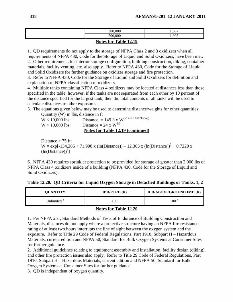
318 AFMAN91-201 12 JANUARY 2011
300,000 1,607
500,000 1,905
Notes for Table 12.19
1. QD requirements do not apply to the storage of NFPA Class 2 and 3 oxidizers when all
requirements of NFPA 430, Code for the Storage of Liquid and Solid Oxidizers, have been met.
2. Other requirements for interior storage configuration, building construction, diking, container
materials, facility venting, etc. also apply. Refer to NFPA 430, Code for the Storage of Liquid
and Solid Oxidizers for further guidance on oxidizer storage and fire protection.
3. Refer to NFPA 430, Code for the Storage of Liquid and Solid Oxidizers for definition and
explanation of NFPA classification of oxidizers.
4. Multiple tanks containing NFPA Class 4 oxidizers may be located at distances less than those
specified in the table; however, if the tanks are not separated from each other by 10 percent of
the distance specified for the largest tank, then the total contents of all tanks will be used to
calculate distances to other exposures.
5. The equations given below may be used to determine distance/weights for other quantities:
Quantity (W) in lbs, distance in ft
W 10,000 lbs: Distance = 149.3 x W(-0.41+0.059*ln(W))
W > 10,000 lbs: Distance = 24 x W1/3
Notes for Table 12.19 (continued)
Distance > 75 ft:
W = exp[-134.286 + 71.998 x (ln(Distance)) – 12.363 x (ln(Distance))2 + 0.7229 x
(ln(Distance))3]
6. NFPA 430 requires sprinkler protection to be provided for storage of greater than 2,000 lbs of
NFPA Class 4 oxidizers inside of a building (NFPA 430, Code for the Storage of Liquid and
Solid Oxidizers).
Table 12.20. QD Criteria for Liquid Oxygen Storage in Detached Buildings or Tanks. 1, 2
QUANTITY IBD/PTRD (ft) ILD/ABOVEGROUND IMD (ft)
Unlimited 3 100 100
4
Notes for Table 12.20
1. Per NFPA 251, Standard Methods of Tests of Endurance of Building Construction and
Materials, distances do not apply where a protective structure having an NFPA fire resistance
rating of at least two hours interrupts the line of sight between the oxygen system and the
exposure. Refer to Title 29 Code of Federal Regulations, Part 1910, Subpart H – Hazardous
Materials, current edition and NFPA 50, Standard for Bulk Oxygen Systems at Consumer Sites
for further guidance.
2. Additional guidelines relating to equipment assembly and installation, facility design (diking),
and other fire protection issues also apply. Refer to Title 29 Code of Federal Regulations, Part
1910, Subpart H – Hazardous Materials, current edition and NFPA 50, Standard for Bulk
Oxygen Systems at Consumer Sites for further guidance.
3. QD is independent of oxygen quantity.
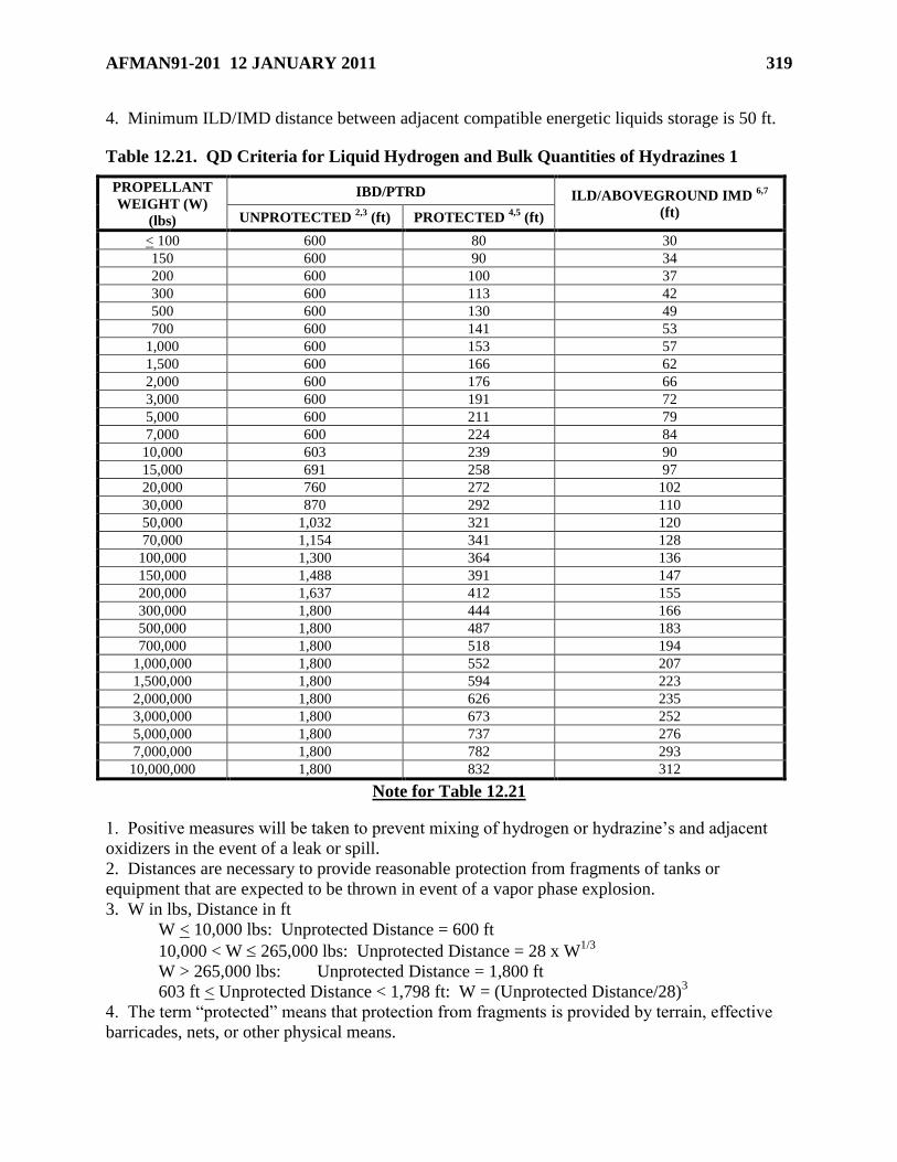
AFMAN91-201 12 JANUARY 2011 319
4. Minimum ILD/IMD distance between adjacent compatible energetic liquids storage is 50 ft.
Table 12.21. QD Criteria for Liquid Hydrogen and Bulk Quantities of Hydrazines 1
PROPELLANT
WEIGHT (W)
(lbs)
IBD/PTRD ILD/ABOVEGROUND IMD 6,7
(ft) UNPROTECTED 2,3
(ft) PROTECTED 4,5
(ft)
< 100 600 80 30
150 600 90 34
200 600 100 37
300 600 113 42
500 600 130 49
700 600 141 53
1,000 600 153 57
1,500 600 166 62
2,000 600 176 66
3,000 600 191 72
5,000 600 211 79
7,000 600 224 84
10,000 603 239 90
15,000 691 258 97
20,000 760 272 102
30,000 870 292 110
50,000 1,032 321 120
70,000 1,154 341 128
100,000 1,300 364 136
150,000 1,488 391 147
200,000 1,637 412 155
300,000 1,800 444 166
500,000 1,800 487 183
700,000 1,800 518 194
1,000,000 1,800 552 207
1,500,000 1,800 594 223
2,000,000 1,800 626 235
3,000,000 1,800 673 252
5,000,000 1,800 737 276
7,000,000 1,800 782 293
10,000,000 1,800 832 312
Note for Table 12.21
1. Positive measures will be taken to prevent mixing of hydrogen or hydrazine’s and adjacent
oxidizers in the event of a leak or spill.
2. Distances are necessary to provide reasonable protection from fragments of tanks or
equipment that are expected to be thrown in event of a vapor phase explosion.
3. W in lbs, Distance in ft
W < 10,000 lbs: Unprotected Distance = 600 ft
10,000 < W 265,000 lbs: Unprotected Distance = 28 x W1/3
W > 265,000 lbs: Unprotected Distance = 1,800 ft
603 ft < Unprotected Distance < 1,798 ft: W = (Unprotected Distance/28)3
4. The term ―protected‖ means that protection from fragments is provided by terrain, effective
barricades, nets, or other physical means.
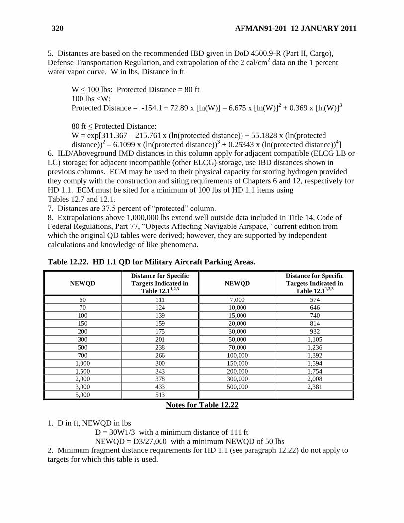
320 AFMAN91-201 12 JANUARY 2011
5. Distances are based on the recommended IBD given in DoD 4500.9-R (Part II, Cargo),
Defense Transportation Regulation, and extrapolation of the 2 cal/cm2 data on the 1 percent
water vapor curve. W in lbs, Distance in ft
W < 100 lbs: Protected Distance = 80 ft
100 lbs <W:
Protected Distance = -154.1 + 72.89 x [ln(W)] – 6.675 x [ln(W)]2 + 0.369 x [ln(W)]
3
80 ft < Protected Distance:
W = exp[311.367 – 215.761 x (ln(protected distance)) + 55.1828 x (ln(protected
distance))2 – 6.1099 x (ln(protected distance))
3 + 0.25343 x (ln(protected distance))
4]
6. ILD/Aboveground IMD distances in this column apply for adjacent compatible (ELCG LB or
LC) storage; for adjacent incompatible (other ELCG) storage, use IBD distances shown in
previous columns. ECM may be used to their physical capacity for storing hydrogen provided
they comply with the construction and siting requirements of Chapters 6 and 12, respectively for
HD 1.1. ECM must be sited for a minimum of 100 lbs of HD 1.1 items using
Tables 12.7 and 12.1.
7. Distances are 37.5 percent of ―protected‖ column.
8. Extrapolations above 1,000,000 lbs extend well outside data included in Title 14, Code of
Federal Regulations, Part 77, ―Objects Affecting Navigable Airspace,‖ current edition from
which the original QD tables were derived; however, they are supported by independent
calculations and knowledge of like phenomena.
Table 12.22. HD 1.1 QD for Military Aircraft Parking Areas.
NEWQD
Distance for Specific
Targets Indicated in
Table 12.11,2,3
NEWQD
Distance for Specific
Targets Indicated in
Table 12.11,2,3
50 111 7,000 574
70 124 10,000 646
100 139 15,000 740
150 159 20,000 814
200 175 30,000 932
300 201 50,000 1,105
500 238 70,000 1,236
700 266 100,000 1,392
1,000 300 150,000 1,594
1,500 343 200,000 1,754
2,000 378 300,000 2,008
3,000 433 500,000 2,381
5,000 513
Notes for Table 12.22
1. D in ft, NEWQD in lbs
D = 30W1/3 with a minimum distance of 111 ft
NEWQD = D3/27,000 with a minimum NEWQD of 50 lbs
2. Minimum fragment distance requirements for HD 1.1 (see paragraph 12.22) do not apply to
targets for which this table is used.
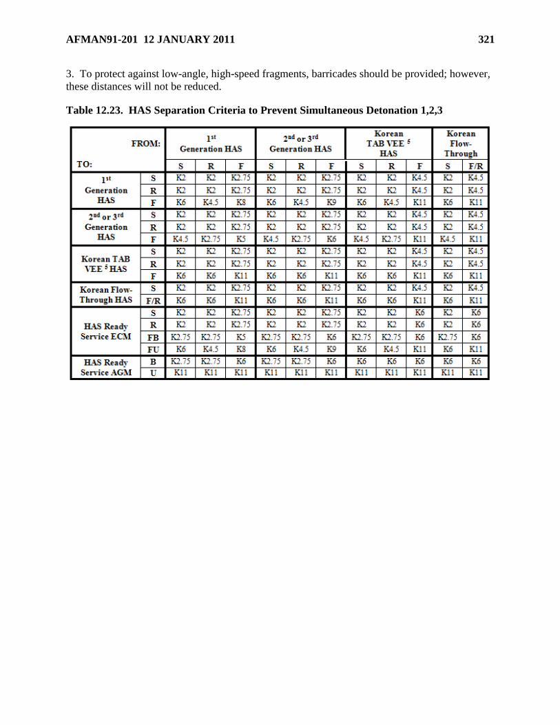
AFMAN91-201 12 JANUARY 2011 321
3. To protect against low-angle, high-speed fragments, barricades should be provided; however,
these distances will not be reduced.
Table 12.23. HAS Separation Criteria to Prevent Simultaneous Detonation 1,2,3
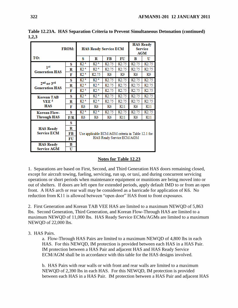
322 AFMAN91-201 12 JANUARY 2011
Table 12.23A. HAS Separation Criteria to Prevent Simultaneous Detonation (continued)
1,2,3
Notes for Table 12.23
1. Separations are based on First, Second, and Third Generation HAS doors remaining closed,
except for aircraft towing, fueling, servicing, run up, or taxi, and during concurrent servicing
operations or short periods when maintenance equipment or munitions are being moved into or
out of shelters. If doors are left open for extended periods, apply default IMD to or from an open
front. A HAS arch or rear wall may be considered as a barricade for application of K6. No
reduction from K11 is allowed between ―open door‖ HAS front to front exposures.
2. First Generation and Korean TAB VEE HAS are limited to a maximum NEWQD of 5,863
lbs. Second Generation, Third Generation, and Korean Flow-Through HAS are limited to a
maximum NEWQD of 11,000 lbs. HAS Ready Service ECMs/AGMs are limited to a maximum
NEWQD of 22,000 lbs.
3. HAS Pairs.
a. Flow-Through HAS Pairs are limited to a maximum NEWQD of 4,800 lbs in each
HAS. For this NEWQD, IM protection is provided between each HAS in a HAS Pair.
IM protection between a HAS Pair and adjacent HAS and HAS Ready Service
ECM/AGM shall be in accordance with this table for the HAS designs involved.
b. HAS Pairs with rear walls or with front and rear walls are limited to a maximum
NEWQD of 2,390 lbs in each HAS. For this NEWQD, IM protection is provided
between each HAS in a HAS Pair. IM protection between a HAS Pair and adjacent HAS
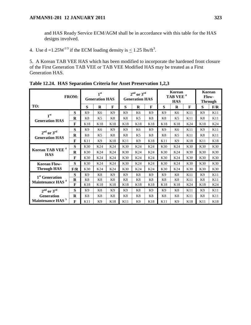
AFMAN91-201 12 JANUARY 2011 323
and HAS Ready Service ECM/AGM shall be in accordance with this table for the HAS
designs involved.
4. Use d =1.25W1/3
if the ECM loading density is < 1.25 lbs/ft3.
5. A Korean TAB VEE HAS which has been modified to incorporate the hardened front closure
of the First Generation TAB VEE or TAB VEE Modified HAS may be treated as a First
Generation HAS.
Table 12.24. HAS Separation Criteria for Asset Preservation 1,2,3
FROM:
TO:
1st
Generation HAS
2nd
or 3rd
Generation HAS
Korean
TAB VEE 4
HAS
Korean
Flow-
Through
S R F S R F S R F S F/R
1st
Generation HAS
S K9 K6 K9 K9 K6 K9 K9 K6 K11 K9 K11
R K8 K5 K8 K8 K5 K8 K8 K5 K11 K8 K11
F K18 K18 K18 K18 K18 K18 K18 K18 K24 K18 K24
2nd
or 3rd
Generation HAS
S K9 K6 K9 K9 K6 K9 K9 K6 K11 K9 K11
R K8 K5 K8 K8 K5 K8 K8 K5 K11 K8 K11
F K11 K9 K18 K11 K9 K18 K11 K9 K18 K11 K18
Korean TAB VEE 4
HAS
S K30 K24 K24 K30 K24 K24 K30 K24 K30 K30 K30
R K30 K24 K24 K30 K24 K24 K30 K24 K30 K30 K30
F K30 K24 K24 K30 K24 K24 K30 K24 K30 K30 K30
Korean Flow-
Through HAS
S K30 K24 K24 K30 K24 K24 K30 K24 K30 K30 K30
F/R K30 K24 K24 K30 K24 K24 K30 K24 K30 K30 K30
1st Generation
Maintenance HAS 4
S K9 K8 K9 K9 K8 K9 K9 K8 K11 K9 K11
R K8 K8 K8 K8 K8 K8 K8 K8 K11 K8 K11
F K18 K18 K18 K18 K18 K18 K18 K18 K24 K18 K24
2nd
or 3rd
Generation
Maintenance HAS 5
S K9 K8 K9 K9 K8 K9 K9 K8 K11 K9 K11
R K8 K8 K8 K8 K8 K8 K8 K8 K11 K8 K11
F K11 K9 K18 K11 K9 K18 K11 K9 K18 K11 K18
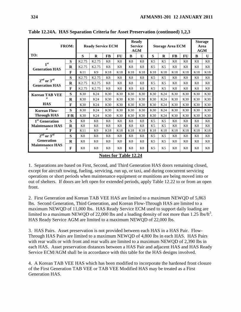
324 AFMAN91-201 12 JANUARY 2011
Table 12.24A. HAS Separation Criteria for Asset Preservation (continued) 1,2,3
Notes for Table 12.24
1. Separations are based on First, Second, and Third Generation HAS doors remaining closed,
except for aircraft towing, fueling, servicing, run up, or taxi, and during concurrent servicing
operations or short periods when maintenance equipment or munitions are being moved into or
out of shelters. If doors are left open for extended periods, apply Table 12.22 to or from an open
front.
2. First Generation and Korean TAB VEE HAS are limited to a maximum NEWQD of 5,863
lbs. Second Generation, Third Generation, and Korean Flow-Through HAS are limited to a
maximum NEWQD of 11,000 lbs. HAS Ready Service ECM used to support daily loading are
limited to a maximum NEWQD of 22,000 lbs and a loading density of not more than 1.25 lbs/ft3.
HAS Ready Service AGM are limited to a maximum NEWQD of 22,000 lbs.
3. HAS Pairs. Asset preservation is not provided between each HAS in a HAS Pair. Flow-
Through HAS Pairs are limited to a maximum NEWQD of 4,800 lbs in each HAS. HAS Pairs
with rear walls or with front and rear walls are limited to a maximum NEWQD of 2,390 lbs in
each HAS. Asset preservation distances between a HAS Pair and adjacent HAS and HAS Ready
Service ECM/AGM shall be in accordance with this table for the HAS designs involved.
4. A Korean TAB VEE HAS which has been modified to incorporate the hardened front closure
of the First Generation TAB VEE or TAB VEE Modified HAS may be treated as a First
Generation HAS.
FROM:
TO:
Ready Service ECM
Ready
Service
AGM
Storage Area ECM
Storage
Area
AGM
S R FB FU B U S R FB FU B U
1st
Generation HAS
S K2.75 K2.75 K8 K8 K8 K8 K5 K5 K8 K8 K8 K8
R K2.75 K2.75 K8 K8 K8 K8 K5 K5 K8 K8 K8 K8
F K11 K9 K18 K18 K18 K18 K18 K18 K18 K18 K18 K18
2nd
or 3rd
Generation HAS
S K2.75 K2.75 K8 K8 K8 K8 K5 K5 K8 K8 K8 K8
R K2.75 K2.75 K8 K8 K8 K8 K5 K5 K8 K8 K8 K8
F K2.75 K2.75 K8 K8 K8 K8 K5 K5 K8 K8 K8 K8
Korean TAB VEE 4
HAS
S K30 K24 K30 K30 K30 K30 K30 K24 K30 K30 K30 K30
R K30 K24 K30 K30 K30 K30 K30 K24 K30 K30 K30 K30
F K30 K24 K30 K30 K30 K30 K30 K24 K30 K30 K30 K30
Korean Flow-
Through HAS
S K30 K24 K30 K30 K30 K30 K30 K24 K30 K30 K30 K30
F/R K30 K24 K30 K30 K30 K30 K30 K24 K30 K30 K30 K30
1st Generation
Maintenance HAS 4
S K8 K8 K8 K8 K8 K8 K5 K5 K8 K8 K8 K8
R K8 K8 K8 K8 K8 K8 K5 K5 K8 K8 K8 K8
F K11 K9 K18 K18 K18 K18 K18 K18 K18 K18 K18 K18
2nd
or 3rd
Generation
Maintenance HAS 5
S K8 K8 K8 K8 K8 K8 K5 K5 K8 K8 K8 K8
R K8 K8 K8 K8 K8 K8 K5 K5 K8 K8 K8 K8
F K8 K8 K8 K8 K8 K8 K5 K5 K8 K8 K8 K8
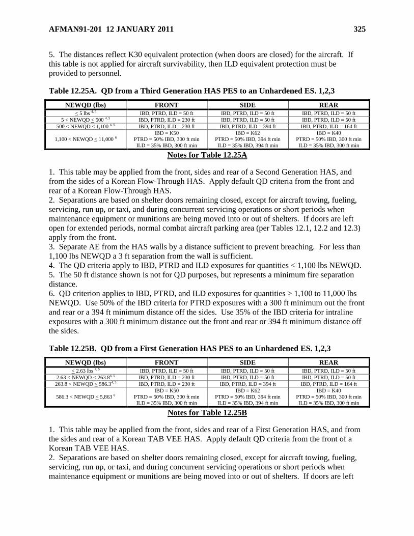
AFMAN91-201 12 JANUARY 2011 325
5. The distances reflect K30 equivalent protection (when doors are closed) for the aircraft. If
this table is not applied for aircraft survivability, then ILD equivalent protection must be
provided to personnel.
Table 12.25A. QD from a Third Generation HAS PES to an Unhardened ES. 1,2,3
NEWQD (lbs) FRONT SIDE REAR
< 5 lbs 4, 5 IBD, PTRD, ILD = 50 ft IBD, PTRD, ILD = 50 ft IBD, PTRD, ILD = 50 ft
5 < NEWQD < 500 4, 5 IBD, PTRD, ILD = 230 ft IBD, PTRD, ILD = 50 ft IBD, PTRD, ILD = 50 ft
500 < NEWQD < 1,100 4, 5 IBD, PTRD, ILD = 230 ft IBD, PTRD, ILD = 394 ft IBD, PTRD, ILD = 164 ft
1,100 < NEWQD < 11,000 6 IBD = K50
PTRD = 50% IBD, 300 ft min
ILD = 35% IBD, 300 ft min
IBD = K62 PTRD = 50% IBD, 394 ft min
ILD = 35% IBD, 394 ft min
IBD = K40 PTRD = 50% IBD, 300 ft min
ILD = 35% IBD, 300 ft min
Notes for Table 12.25A
1. This table may be applied from the front, sides and rear of a Second Generation HAS, and
from the sides of a Korean Flow-Through HAS. Apply default QD criteria from the front and
rear of a Korean Flow-Through HAS.
2. Separations are based on shelter doors remaining closed, except for aircraft towing, fueling,
servicing, run up, or taxi, and during concurrent servicing operations or short periods when
maintenance equipment or munitions are being moved into or out of shelters. If doors are left
open for extended periods, normal combat aircraft parking area (per Tables 12.1, 12.2 and 12.3)
apply from the front.
3. Separate AE from the HAS walls by a distance sufficient to prevent breaching. For less than
1,100 lbs NEWQD a 3 ft separation from the wall is sufficient.
4. The QD criteria apply to IBD, PTRD and ILD exposures for quantities < 1,100 lbs NEWQD.
5. The 50 ft distance shown is not for QD purposes, but represents a minimum fire separation
distance.
6. QD criterion applies to IBD, PTRD, and ILD exposures for quantities > 1,100 to 11,000 lbs
NEWQD. Use 50% of the IBD criteria for PTRD exposures with a 300 ft minimum out the front
and rear or a 394 ft minimum distance off the sides. Use 35% of the IBD criteria for intraline
exposures with a 300 ft minimum distance out the front and rear or 394 ft minimum distance off
the sides.
Table 12.25B. QD from a First Generation HAS PES to an Unhardened ES. 1,2,3
NEWQD (lbs) FRONT SIDE REAR
< 2.63 lbs 4, 5 IBD, PTRD, ILD = 50 ft IBD, PTRD, ILD = 50 ft IBD, PTRD, ILD = 50 ft
2.63 < NEWQD < 263.84, 5 IBD, PTRD, ILD = 230 ft IBD, PTRD, ILD = 50 ft IBD, PTRD, ILD = 50 ft
263.8 < NEWQD < 586.34, 5 IBD, PTRD, ILD = 230 ft IBD, PTRD, ILD = 394 ft IBD, PTRD, ILD = 164 ft
586.3 < NEWQD < 5,863 6
IBD = K50
PTRD = 50% IBD, 300 ft min ILD = 35% IBD, 300 ft min
IBD = K62
PTRD = 50% IBD, 394 ft min ILD = 35% IBD, 394 ft min
IBD = K40
PTRD = 50% IBD, 300 ft min ILD = 35% IBD, 300 ft min
Notes for Table 12.25B
1. This table may be applied from the front, sides and rear of a First Generation HAS, and from
the sides and rear of a Korean TAB VEE HAS. Apply default QD criteria from the front of a
Korean TAB VEE HAS.
2. Separations are based on shelter doors remaining closed, except for aircraft towing, fueling,
servicing, run up, or taxi, and during concurrent servicing operations or short periods when
maintenance equipment or munitions are being moved into or out of shelters. If doors are left
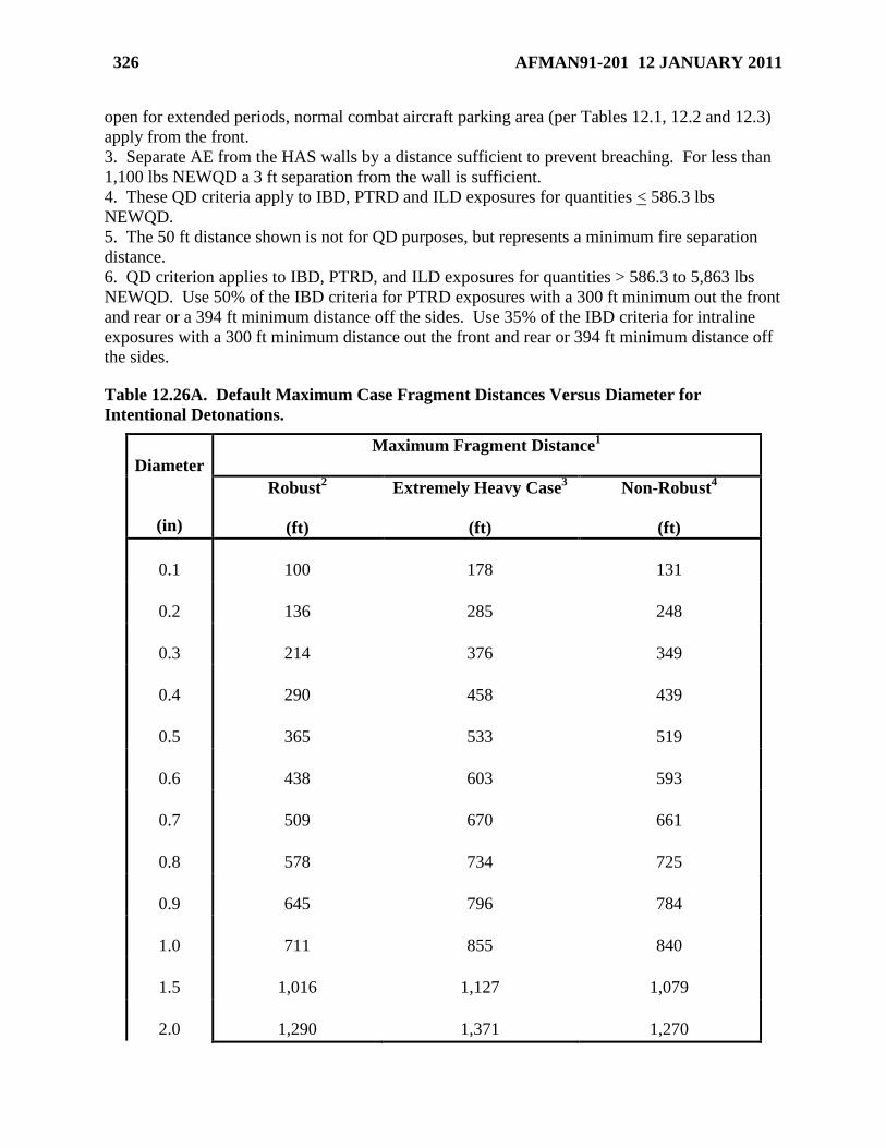
326 AFMAN91-201 12 JANUARY 2011
open for extended periods, normal combat aircraft parking area (per Tables 12.1, 12.2 and 12.3)
apply from the front.
3. Separate AE from the HAS walls by a distance sufficient to prevent breaching. For less than
1,100 lbs NEWQD a 3 ft separation from the wall is sufficient.
4. These QD criteria apply to IBD, PTRD and ILD exposures for quantities < 586.3 lbs
NEWQD.
5. The 50 ft distance shown is not for QD purposes, but represents a minimum fire separation
distance.
6. QD criterion applies to IBD, PTRD, and ILD exposures for quantities > 586.3 to 5,863 lbs
NEWQD. Use 50% of the IBD criteria for PTRD exposures with a 300 ft minimum out the front
and rear or a 394 ft minimum distance off the sides. Use 35% of the IBD criteria for intraline
exposures with a 300 ft minimum distance out the front and rear or 394 ft minimum distance off
the sides.
Table 12.26A. Default Maximum Case Fragment Distances Versus Diameter for
Intentional Detonations.
Diameter
(in)
Maximum Fragment Distance1
Robust2
(ft)
Extremely Heavy Case3
(ft)
Non-Robust4
(ft)
0.1
100
178
131
0.2
136
285
248
0.3
214
376
349
0.4
290
458
439
0.5
365
533
519
0.6
438
603
593
0.7
509
670
661
0.8
578
734
725
0.9
645
796
784
1.0
711
855
840
1.5
1,016
1,127
1,079
2.0
1,290
1,371
1,270
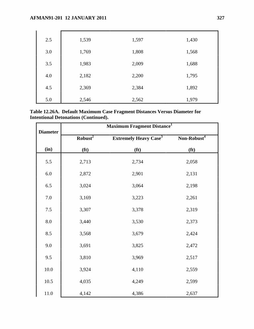
AFMAN91-201 12 JANUARY 2011 327
2.5
1,539
1,597
1,430
3.0
1,769
1,808
1,568
3.5
1,983
2,009
1,688
4.0
2,182
2,200
1,795
4.5
2,369
2,384
1,892
5.0
2,546
2,562
1,979
Table 12.26A. Default Maximum Case Fragment Distances Versus Diameter for
Intentional Detonations (Continued).
Diameter
(in)
Maximum Fragment Distance1
Robust2
(ft)
Extremely Heavy Case3
(ft)
Non-Robust4
(ft)
5.5
2,713
2,734
2,058
6.0
2,872
2,901
2,131
6.5
3,024
3,064
2,198
7.0
3,169
3,223
2,261
7.5
3,307
3,378
2,319
8.0
3,440
3,530
2,373
8.5
3,568
3,679
2,424
9.0
3,691
3,825
2,472
9.5
3,810
3,969
2,517
10.0
3,924
4,110
2,559
10.5
4,035
4,249
2,599
11.0
4,142
4,386
2,637
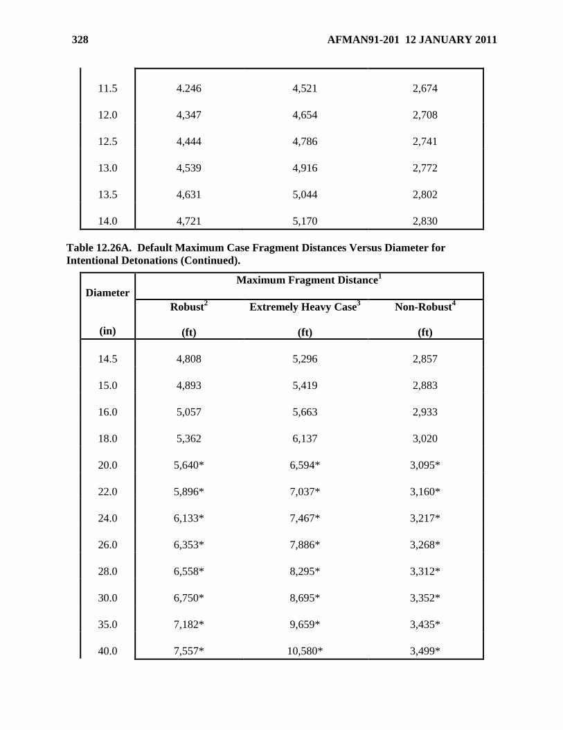
328 AFMAN91-201 12 JANUARY 2011
11.5
4.246
4,521
2,674
12.0
4,347
4,654
2,708
12.5
4,444
4,786
2,741
13.0
4,539
4,916
2,772
13.5
4,631
5,044
2,802
14.0
4,721
5,170
2,830
Table 12.26A. Default Maximum Case Fragment Distances Versus Diameter for
Intentional Detonations (Continued).
Diameter
(in)
Maximum Fragment Distance1
Robust2
(ft)
Extremely Heavy Case3
(ft)
Non-Robust4
(ft)
14.5
4,808
5,296
2,857
15.0
4,893
5,419
2,883
16.0
5,057
5,663
2,933
18.0
5,362
6,137
3,020
20.0
5,640*
6,594*
3,095*
22.0
5,896*
7,037*
3,160*
24.0
6,133*
7,467*
3,217*
26.0
6,353*
7,886*
3,268*
28.0
6,558*
8,295*
3,312*
30.0
6,750*
8,695*
3,352*
35.0
7,182*
9,659*
3,435*
40.0
7,557*
10,580*
3,499*
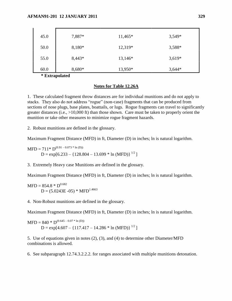
AFMAN91-201 12 JANUARY 2011 329
45.0
7,887*
11,465*
3,549*
50.0
8,180*
12,319*
3,588*
55.0
8,443*
13,146*
3,619*
60.0
8,680*
13,950*
3,644*
* Extrapolated
Notes for Table 12.26A
1. These calculated fragment throw distances are for individual munitions and do not apply to
stacks. They also do not address ―rogue‖ (non-case) fragments that can be produced from
sections of nose plugs, base plates, boattails, or lugs. Rogue fragments can travel to significantly
greater distances (i.e., >10,000 ft) than those shown. Care must be taken to properly orient the
munition or take other measures to minimize rogue fragment hazards.
2. Robust munitions are defined in the glossary.
Maximum Fragment Distance (MFD) in ft, Diameter (D) in inches; ln is natural logarithm.
MFD = 711* D(0.91 – 0.073 * ln (D))
D = exp[6.233 – {128.804 – 13.699 * ln (MFD)} 1/2
]
3. Extremely Heavy case Munitions are defined in the glossary.
Maximum Fragment Distance (MFD) in ft, Diameter (D) in inches; ln is natural logarithm.
MFD = 854.8 * D0.682
D = (5.0243E -05) * MFD1.4663
4. Non-Robust munitions are defined in the glossary.
Maximum Fragment Distance (MFD) in ft, Diameter (D) in inches; ln is natural logarithm.
MFD = 840 * D(0.645 – 0.07 * ln (D))
D = exp[4.607 – {117.417 – 14.286 * ln (MFD)} 1/2
]
5. Use of equations given in notes (2), (3), and (4) to determine other Diameter/MFD
combinations is allowed.
6. See subparagraph 12.74.3.2.2.2. for ranges associated with multiple munitions detonation.
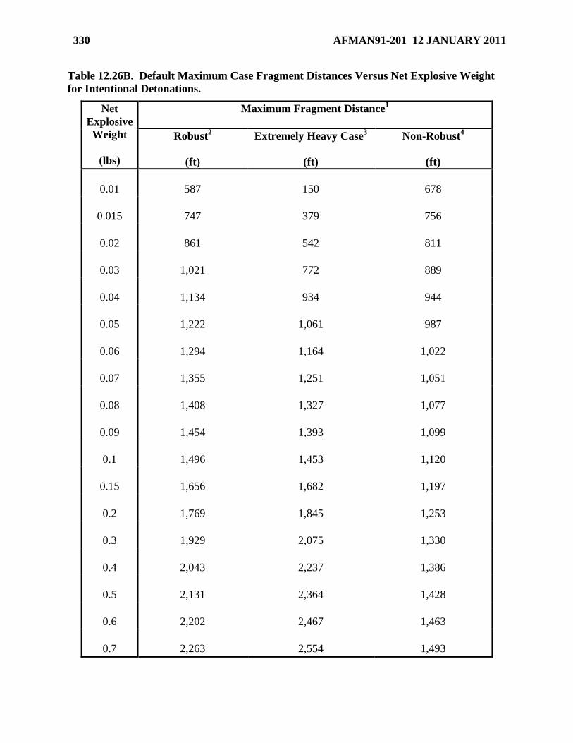
330 AFMAN91-201 12 JANUARY 2011
Table 12.26B. Default Maximum Case Fragment Distances Versus Net Explosive Weight
for Intentional Detonations.
Net
Explosive
Weight
(lbs)
Maximum Fragment Distance1
Robust2
(ft)
Extremely Heavy Case3
(ft)
Non-Robust4
(ft)
0.01
587
150
678
0.015
747
379
756
0.02
861
542
811
0.03
1,021
772
889
0.04
1,134
934
944
0.05
1,222
1,061
987
0.06
1,294
1,164
1,022
0.07
1,355
1,251
1,051
0.08
1,408
1,327
1,077
0.09
1,454
1,393
1,099
0.1
1,496
1,453
1,120
0.15
1,656
1,682
1,197
0.2
1,769
1,845
1,253
0.3
1,929
2,075
1,330
0.4
2,043
2,237
1,386
0.5
2,131
2,364
1,428
0.6
2,202
2,467
1,463
0.7
2,263
2,554
1,493
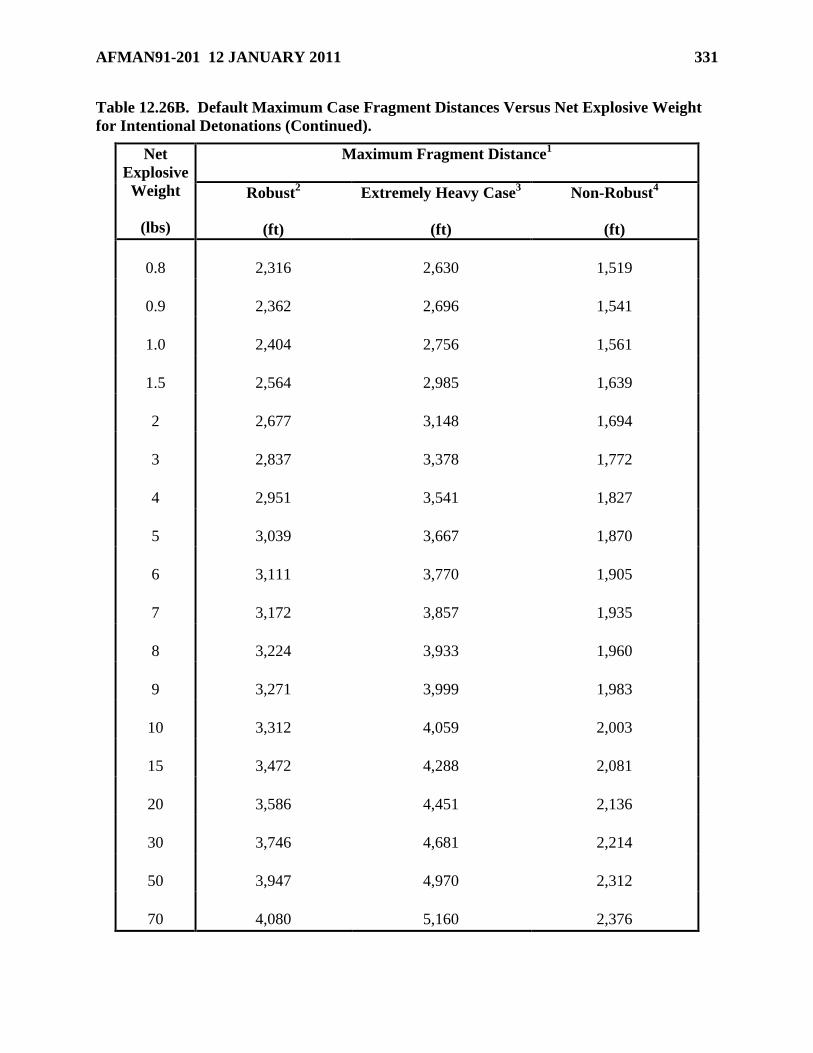
AFMAN91-201 12 JANUARY 2011 331
Table 12.26B. Default Maximum Case Fragment Distances Versus Net Explosive Weight
for Intentional Detonations (Continued).
Net
Explosive
Weight
(lbs)
Maximum Fragment Distance1
Robust2
(ft)
Extremely Heavy Case3
(ft)
Non-Robust4
(ft)
0.8
2,316
2,630
1,519
0.9
2,362
2,696
1,541
1.0
2,404
2,756
1,561
1.5
2,564
2,985
1,639
2
2,677
3,148
1,694
3
2,837
3,378
1,772
4
2,951
3,541
1,827
5
3,039
3,667
1,870
6
3,111
3,770
1,905
7
3,172
3,857
1,935
8
3,224
3,933
1,960
9
3,271
3,999
1,983
10
3,312
4,059
2,003
15
3,472
4,288
2,081
20
3,586
4,451
2,136
30
3,746
4,681
2,214
50
3,947
4,970
2,312
70
4,080
5,160
2,376
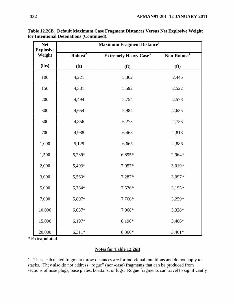
332 AFMAN91-201 12 JANUARY 2011
Table 12.26B. Default Maximum Case Fragment Distances Versus Net Explosive Weight
for Intentional Detonations (Continued).
Net
Explosive
Weight
(lbs)
Maximum Fragment Distance1
Robust2
(ft)
Extremely Heavy Case3
(ft)
Non-Robust4
(ft)
100
4,221
5,362
2,445
150
4,381
5,592
2,522
200
4,494
5,754
2,578
300
4,654
5,984
2,655
500
4,856
6,273
2,753
700
4,988
6,463
2,818
1,000
5,129
6,665
2,886
1,500
5,289*
6,895*
2,964*
2,000
5,403*
7,057*
3,019*
3,000
5,563*
7,287*
3,097*
5,000
5,764*
7,576*
3,195*
7,000
5,897*
7,766*
3,259*
10,000
6,037*
7,968*
3,328*
15,000
6,197*
8,198*
3,406*
20,000
6,311*
8,360*
3,461*
* Extrapolated
Notes for Table 12.26B
1. These calculated fragment throw distances are for individual munitions and do not apply to
stacks. They also do not address ―rogue‖ (non-case) fragments that can be produced from
sections of nose plugs, base plates, boattails, or lugs. Rogue fragments can travel to significantly
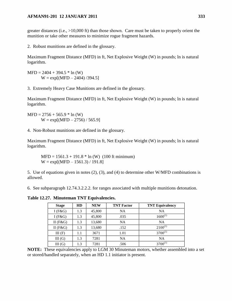
AFMAN91-201 12 JANUARY 2011 333
greater distances (i.e., >10,000 ft) than those shown. Care must be taken to properly orient the
munition or take other measures to minimize rogue fragment hazards.
2. Robust munitions are defined in the glossary.
Maximum Fragment Distance (MFD) in ft, Net Explosive Weight (W) in pounds; ln is natural
logarithm.
MFD = 2404 + 394.5 * ln (W)
W = exp[(MFD – 2404) /394.5]
3. Extremely Heavy Case Munitions are defined in the glossary.
Maximum Fragment Distance (MFD) in ft, Net Explosive Weight (W) in pounds; ln is natural
logarithm.
MFD = 2756 + 565.9 * ln (W)
W = exp[(MFD – 2756) / 565.9]
4. Non-Robust munitions are defined in the glossary.
Maximum Fragment Distance (MFD) in ft, Net Explosive Weight (W) in pounds; ln is natural
logarithm.
MFD = 1561.3 + 191.8 * ln (W) (100 ft minimum)
W = exp[(MFD – 1561.3) / 191.8]
5. Use of equations given in notes (2), (3), and (4) to determine other W/MFD combinations is
allowed.
6. See subparagraph 12.74.3.2.2.2. for ranges associated with multiple munitions detonation.
Table 12.27. Minuteman TNT Equivalencies.
Stage HD NEW TNT Factor TNT Equivalency
I (F&G) 1.3 45,800 NA NA
I (F&G) 1.3 45,800 .035 1600(1)
II (F&G) 1.3 13,680 NA NA
II (F&G) 1.3 13,680 .152 2100(1)
III (F) 1.1 3671 1.01 3700(1)
III (G) 1.3 7281 NA NA
III (G) 1.3 7281 .506 3700(1)
NOTE: These equivalencies apply to LGM 30 Minuteman motors, whether assembled into a set
or stored/handled separately, when an HD 1.1 initiator is present.

334 AFMAN91-201 12 JANUARY 2011
Table 12.28. Peacekeeper TNT Equivalencies.
Stage HD NEW TNT Factor TNT Equivalency
I 1.3 99,133 NA NA
I 1.3 99,133 1.20 118960(1)
II 1.3 54,120 NA NA
II 1.3 54,120 1.20 64,944(1)
III 1.1 15,606 1.25 19,508(1)
NOTE: These equivalencies apply to Peacekeeper motors, whether assembled into a set or
stored/handled separately, when a HD 1.1 initiator is present. When stage III’s are stored only
with other stage III’s, the HD 1.1 NEWQD versus TNT equivalency may be used.
Table 12.29. Criteria for Non-DoD Explosives Activities on DoD Installations.
TO
FROM
Non-DoD
Storage
DoD/Joint
Storage
Non-DoD
Operations
DoD
Operations
Shared
Launch
Facilities
DoD Non-Explosives
Facilities/Operations
Non Related
Non-DoD
Storage
Check for
IMD IMD
Check for
IMD IBD IBD IBD
Non-DoD
Operations
Check for
IMD IBD
Check for
IMD IBD IBD IBD
Shared
Launch
Facilities
IBD IBD IBD IBD ILD IBD
DoD/Joint
Storage IMD IMD IBD ILD IBD IBD
DoD
Operations IBD ILD IBD ILD IBD IBD
Table 12.30. QD for HD 1.1 AE For K = 1.1, 1.25, 2, 2.75, 4.5, and 5.
NEWQD
(lbs)
Hazard Factor, K
1.1
(ft/lb1/3
)
1.25
(ft/lb1/3
)
2
(ft/lb1/3
)
2.75
(ft/lb1/3
)
4.5
(ft/lb1/3
)
5
(ft/lb1/3
)
100 7.0 7.0 9.3 13 21 23
150 7.0 7.0 11 15 24 27
200 7.0 7.3 12 16 26 29
300 7.4 8.4 13 18 30 33
500 8.7 9.9 16 22 36 40
700 9.8 11 18 24 40 44
1,000 11 13 20 27 45 50
1,500 13 14 23 31 52 57
2,000 14 16 25 35 57 63
3,000 16 18 29 40 65 72
5,000 19 21 34 47 77 85
7,000 21 24 38 53 86 96
10,000 24 27 43 59 97 108
15,000 27 31 49 68 111 123
20,000 30 34 54 75 122 136
30,000 34 39 62 85 140 155
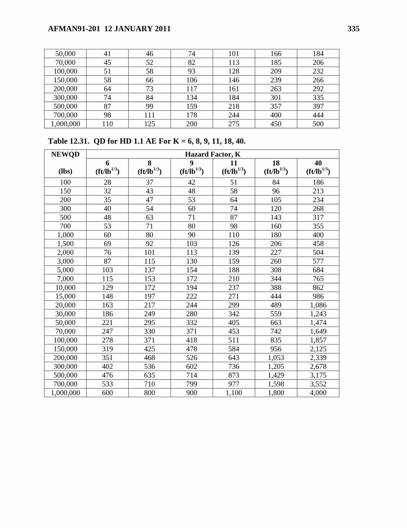
AFMAN91-201 12 JANUARY 2011 335
50,000 41 46 74 101 166 184
70,000 45 52 82 113 185 206
100,000 51 58 93 128 209 232
150,000 58 66 106 146 239 266
200,000 64 73 117 161 263 292
300,000 74 84 134 184 301 335
500,000 87 99 159 218 357 397
700,000 98 111 178 244 400 444
1,000,000 110 125 200 275 450 500
Table 12.31. QD for HD 1.1 AE For K = 6, 8, 9, 11, 18, 40.
NEWQD
(lbs)
Hazard Factor, K
6
(ft/lb1/3
)
8
(ft/lb1/3
)
9
(ft/lb1/3
)
11
(ft/lb1/3
)
18
(ft/lb1/3
)
40
(ft/lb1/3
)
100 28 37 42 51 84 186
150 32 43 48 58 96 213
200 35 47 53 64 105 234
300 40 54 60 74 120 268
500 48 63 71 87 143 317
700 53 71 80 98 160 355
1,000 60 80 90 110 180 400
1,500 69 92 103 126 206 458
2,000 76 101 113 139 227 504
3,000 87 115 130 159 260 577
5,000 103 137 154 188 308 684
7,000 115 153 172 210 344 765
10,000 129 172 194 237 388 862
15,000 148 197 222 271 444 986
20,000 163 217 244 299 489 1,086
30,000 186 249 280 342 559 1,243
50,000 221 295 332 405 663 1,474
70,000 247 330 371 453 742 1,649
100,000 278 371 418 511 835 1,857
150,000 319 425 478 584 956 2,125
200,000 351 468 526 643 1,053 2,339
300,000 402 536 602 736 1,205 2,678
500,000 476 635 714 873 1,429 3,175
700,000 533 710 799 977 1,598 3,552
1,000,000 600 800 900 1,100 1,800 4,000
336 AFMAN91-201 12 JANUARY 2011
Chapter 13
CONTINGENCIES, COMBAT OPERATIONS, MILITARY OPERATIONS
Section 13A—Introduction
13.1. Introduction. Per Joint Publication 1-02, contingencies are emergencies involving
military forces caused by natural disasters, terrorists, subversives, or by required military
operations. Due to the uncertainty of the situation, contingencies require plans, rapid response,
and special procedures to ensure the safety and readiness of personnel, installations, and
equipment. This chapter provides the optional criteria for contingencies, combat operations,
military operations other than war (MOOTW), and associated training. Full compliance with
other chapters of this Manual may not be possible during such operations. In situations
involving combined or joint operations, the Commander of Unified or Specified Command
(Combatant Commander) or the US Commander of a Joint Task Force (JTF) will designate the
Service explosives safety criteria to be used.
13.2. Scope. The provisions of this chapter only apply to:
13.2.1. Those Air Force AE activities located outside the United States.
13.2.2. Combatant Commanders, United States Commanders of JTF or Air Force
Commanders in the management of these Air Force AE activities. When necessary,
commanders may delegate certain explosive safety responsibilities to designated subordinate
commanders to ensure appropriate controls.
13.2.3. Contingency, combat, and MOOTW training, regardless of location, when
specifically authorized by applicable Air Force headquarters or Unified Command
Commander. Prior to approval of this training, a risk analysis that thoroughly assesses asset
preservation and identifies the risk associated with the training will be conducted. QD
separations provided for asset preservation will be used for training, except where Chapter 12
permits lesser distances to be used.
13.3. Contingencies, Combat Operations, MOOTW, and Associated
Training. Contingency, combat operations and MOOTW refer to operations that a unit actually
conducts during or leading up to a contingency, combat, or MOOTW situation. These operations
may actually occur as previously defined by the operational plan, may be modified from the
operational plan, or may be newly defined if an operational plan did not exist prior to the
contingency, combat, or MOOTW situation. Associated training refers to training occurring in
the immediate support of an impending or on-going contingency, combat, or MOOTW situation
(e.g., UTC training in support of AEF rotation or tasking); routine training falls under day-to-day
operations per paragraph 1.2.1.6.1.
13.4. Asset Preservation and Minimum Separation Distances. This chapter provides
optional criteria and risk management tools not available elsewhere in this Manual. These
optional criteria provide greater protection (asset preservation distance) for assets deemed
sufficiently critical to warrant the greater protection, and, in some circumstances, provide lesser
protection (minimum separation distance) for those assets for which the mission requirements
AFMAN91-201 12 JANUARY 2011 337
outweigh the increased risk to those assets. See chapter 12 for paired relationships not covered
in this section.
13.4.1. Asset preservation distance. At this distance from the PES, assets at the ES are
expected to be usable and mission capability is maintained following an incident. This
separation distance should prevent propagation between PES. (See DoD 6055.09-M, DoD
Ammunition and Explosives Safety Standards, for expected consequences for these separation
distances.)
13.4.2. Minimum separation distance. At this distance from the PES, mission capability
will likely be impaired or delayed. This separation distance should prevent prompt
propagation; however, late time propagation between PES is possible. (See DoD 6055.09-M,
DoD Ammunition and Explosives Safety Standards, for expected consequences for these
separation distances.)
Section 13B—Planning for Deployments
13.5. Planning for Deployments.
13.5.1. The requirements of this Manual also apply to contingencies, peacetime
deployments, and exercises where explosives are involved. At no time is the observance of
explosives safety practices more important than when deploying or employing combat forces.
Explosives safety is an integral part of combat survivability.
13.5.2. Pay careful attention during planning to ensure compliance with explosives QD rules
as discussed in Annex FF of the Air Force War Mobilization Plan Vol. 1 (WMP1).
13.5.3. MAJCOMs which have units that deploy or support deployed forces will require
these units to develop procedures and explosives site plans for parking explosives-loaded
aircraft, as well as receipt, storage, buildup, and delivery of munitions. Explosives safety
considerations must be an integral part of the site survey team’s visit and subsequent plans
for on-going support and oversight. These procedures and explosives site plans are
developed jointly by operations, civil engineering, logistics, and safety from both augmented
and augmenting MAJCOMs and units. MAJCOMs will make these procedures and
explosives site plans available to deploying units.
13.5.4. Planning for possible deployments includes:
13.5.4.1. A review of waivers and exemptions that may impact deployment plans, such
as those in Attachment 4.
13.5.4.2. Periodic updates as munitions commitments and bed-down locations change.
Include civil engineering concept plans for constructing required aircraft revetments or
protective shelters and munitions storage facilities. For units with a munitions mission
but no specific deployment location, site preplanning must be adaptable to any
deployment location.
13.5.4.3. Locally written instructions (see Section 7B) for all phases of munitions
operations at the deployed location.
13.5.4.4. Briefings to tasked unit personnel on the plans and procedures to be used at the
deployment location.
338 AFMAN91-201 12 JANUARY 2011
13.5.5. MAJCOMs must ensure adequate explosives safety support is available at the
deployment location during planning and bed-down.
13.5.6. The QD priority to maintain during planning and employment of combat forces is:
(1) maintaining intermagazine (IM) separation, (2) meeting intraline (IL) separation, and (3)
protecting unrelated personnel.
13.5.7. See Chapter 14 and Section 13D for explosives site planning requirements. (See Air
Force Pamphlet 91-216, USAF Safety Deployment and Contingency Pamphlet.)
Section 13C—Risk Management
13.6. Risk Management. Consistent with operational requirements, it is Air Force policy to
manage risks associated with AE (see paragraph 1.1). Exceptions to this chapter’s criteria are
allowed only where equivalent protection is provided, or where risk assessment and risk
management control is performed.
13.6.1. Equivalent Protection. Situations where an analysis determines that protective
construction or other specialized safety features provide a level of protection equivalent to
the separation distances required by this Manual.
13.6.2. Risk Assessment. Situations where an assessment determines that an acceptable
level of safety is provided. Risk assessment (see Chapter 4) is a systematic procedure
consisting of the following four steps:
13.6.2.1. An event analysis to identify and describe possible events such as the location,
type of occurrence, probability of occurrence, and quantity of explosives.
13.6.2.2. An effects analysis of the effects of the possible events to persons in the
surroundings such as blast pressure, fragmentation, and thermal hazards.
13.6.2.3. An exposure analysis of the places, protection and time history of exposed
personnel in the hazardous areas.
13.6.2.4. A risk calculation.
13.6.3. Risk Management Control. The action a commander takes to minimize acceptable
risk. Such actions will include:
13.6.3.1. Development, implementation, and enforcement of applicable control measures
used to eliminate the hazard or reduce its risk.
13.6.3.2. Continuous evaluation of the effectiveness of the implemented control
measures.
Section 13D—Explosives Site Planning
13.7. Site Approval. All explosives locations falling within the scope of this chapter will be
approved by the applicable commander or by the DDESB per paragraph 13.8. Site approval
documentation will be submitted:
13.7.1. For AE locations such as the following:
13.7.1.1. Storage locations.
AFMAN91-201 12 JANUARY 2011 339
13.7.1.2. Holding areas (e.g., basic load ammunition holding areas (BLAHA), flight line
holding areas, port and railhead holding areas, and marshalling areas, etc.).
13.7.1.3. Handling and operating locations (e.g., HAS, ports, AE maintenance, repair,
and renovation areas and sling out areas, etc.).
13.7.1.4. Forward arming and refueling points (FARP).
13.7.1.5. Combat aircraft parking area (CAPA) and cargo aircraft parking areas.
13.7.1.6. Static missile batteries.
13.7.1.7. Locations used for the treatment or disposal (e.g., open burn or open
detonation) of munitions. Exceptions are those locations used in an emergency response,
for burning excess propellant resulting from munitions use during training, and those
involved in direct combat operations.
13.7.2. For non-AE exposed sites within quantity-distance (QD) arcs.
13.8. Site Approval and Documentation Requirements. The operational situation and the
type and duration of the AE operations conducted at the site or facility determine the type of
documentation required for a site approval and the approval level. The following categories of
operations apply:
13.8.1. Permanent.
13.8.1.1. Definition. Those AE related facilities where operations are expected to
continue for more than 12 months.
13.8.1.2. Documentation and Approval Requirements. A DDESB approved
explosives site plan for such locations must be obtained once the Combatant Commander
(or Air Force headquarters where applicable) determines operations will require the
facilities’ use to exceed 12 months. Explosives site plans with waivers or exemptions
will be processed in accordance with the ―day-to-day operations‖ requirements of Section
1B.
13.8.2. Recurrent.
13.8.2.1. Definition. Those AE related facilities where operations are expected to occur
on a periodic basis regardless of the duration of the operation. These locations may be
sited using compensatory actions, such as facility evacuation or change-of-use, to
minimize the risks associated with AE operations.
13.8.2.2. Documentation and Approval Requirements. These locations must have a
DDESB (or appropriate level of command when applicable) approved explosives site
plan before commencing operations. Explosives site plans with waivers or exemptions
will be processed in accordance with the ―day-to-day operations‖ requirements of Section
1B.
13.8.3. Temporary.
13.8.3.1. Definition. Those AE related facilities where operations are not expected to
continue for more than 12 months and are not recurrent, or for which advanced planning
and approval are impractical.
340 AFMAN91-201 12 JANUARY 2011
13.8.3.2. Documentation and Approval Requirements. A plan for the specific
scenario will be approved by the applicable commander. The plan will detail the
following:
13.8.3.2.1. A risk assessment for the proposed operation. This assessment will
weigh the need for the facility against the potential effects of a mishap (e.g., mission
impact, loss of resources, turnaround times, etc.).
13.8.3.2.2. Schedule for the cessation of explosives operations or submittal of an
explosives site plan per paragraph 13.8.1 if the operations exceed 12 months.
13.8.4. Contingency, Combat, and MOOTW Training.
13.8.4.1. Definition. Those operations that simulate real world combat environments
using live AE to achieve training goals and occur in the immediate support of an
impending or on-going contingency, combat, or MOOTW situation.
13.8.4.2. Documentation and Approval Requirements. Facilities or areas for training
activities will have a DDESB approved explosives site plan for permanent or recurrent
operations, or a risk analysis approved by the applicable commander for temporary
operations. For permanent or recurrent operations, explosives site plans with waivers or
exemptions will be processed in accordance with the ―day-to-day operations‖
requirements of Section 1B.
13.9. Explosives Site Plan Packages. See Chapter 14 for explosives site plan requirements
with the following changes:
13.9.1. In the absence of suitable maps or drawings, information (e.g., sketches,
photographs, or other information) may be provided.
13.9.2. An explanation of any deviations from pertinent safety standard caused by local
conditions.
13.9.3. A copy of the risk analysis performed, if one was performed, to demonstrate
equivalent protection.
13.10. Approval Authority for Exceptions. The Combatant Commander, United States
Commander of a JTF or Air Force Component Commander, for strategic or other compelling
reasons may authorize exceptions to the explosives safety standards herein for the planning or
conduct of temporary contingencies, combat operations and MOOTW. All exceptions will be
coordinated with the host nation, as required, and consistent with international agreements.
13.10.1. Requests for exceptions to QD criteria will be per Air Force directives. When joint
operations are being conducted from a single base or location, exceptions that affect another
Service must be coordinated with that Service.
13.10.2. Requests for exceptions to QD criteria will contain the following:
13.10.2.1. A risk analysis for the proposed operation weighing the need to conduct the
operation and violate the standards against the potential effect of a mishap (e.g., mission
impact, loss of resources, turnaround times, etc.).
13.10.2.2. A timeline listing milestones which will eliminate the need for the exception.
AFMAN91-201 12 JANUARY 2011 341
13.10.3. For planned construction, in support of temporary contingency, combat operations
or MOOTW, not meeting QD criteria, obtain Combatant Commander, United States
Commander of JTF, or Air Force Component Commander approval.
Section 13E—QD Criteria for Contingencies, Combat Operations, MOOTW and Associated
Training
13.11. Basic Load Ammunition Holding Area (BLAHA).
13.11.1. General. To fulfill their missions, certain units must keep their basic load
ammunition in armored vehicles, trucks, trailers, structures, or on pads. This involves
acceptance of greater risks to unit personnel, facilities, and equipment than permitted by
other chapters of this Standard. The concept of BLAHA storage may also be used to provide
QD separations during mobile operations. A Basic Load Storage Area (BLSA) is a location
containing multiple BLAHA.
13.11.2. Mixing of Basic Load Ammunition. Storage compatibility requirements of
Chapter 7 do not apply to BLAHA facilities.
13.11.2.1. NEWQD for use with BLAHA QD criteria will be determined as follows:
13.11.2.1.1. The sum of the weights of all energetic compositions contained in
munitions hazard classified as HD 1.1 or 1.5 will be used.
13.11.2.1.2. The sum of the explosive weight of all HD 1.2 AE will be used. The
propellant weight of a HD 1.2 item (if present) may be disregarded.
13.11.2.1.3. The weights of energetic compositions hazard classified as HD 1.3 may
be disregarded. However, if the site only contains HD 1.3 items, the criteria
contained in paragraph 12.28 apply.
13.11.2.1.4. The weights of energetic compositions classified as HD 1.4 may be
disregarded.
13.11.2.1.5. The explosive weight of HD 1.6 will be computed as follows:
13.11.2.1.5.1. When HD 1.6 is stored alone or with HD 1.4 AE, the QD criteria
of paragraphs 12.29. and 12.30. apply.
13.11.2.1.5.2. When HD 1.6 is stored with AE classified as HD 1.1, HD 1.2 or
HD 1.5, add the explosives weight of the HD 1.6 items into the NEWQD
calculations.
13.11.2.1.5.3. When HD 1.6 is stored with AE classified as HD 1.3 add the
explosives weights of HD 1.3 and HD 1.6. The QD criteria in paragraph 12.28
apply.
13.11.2.2. Explosives Limits.
13.11.2.2.1. The maximum NEWQD at any BLAHA in a BLSA storing mixed
compatibility must not exceed 8,818 lbs. A BLSA may have multiple 8,818-lb
BLAHA, provided the BLAHA are separated from each other by the applicable
distances (D1, D2 and D3) given in Table 13.1.
342 AFMAN91-201 12 JANUARY 2011
13.11.2.2.2. When the NEWQD of a BLSA or a BLAHA exceeds 8,818 lb, the QD
computations and HD mixing rules for the site will be per Chapter 12 and the
explosives compatibility storage criteria will be per Chapter 7.
13.11.3. QD Computations.
13.11.3.1. The total NEWQD of AE in each site will be used for computation of QD
provided the required distances (Table 13.1) necessary to prevent propagation separate
these sites. If the separation distances are not met, the entire BLSA will be considered
one site and paragraph 13.11.2.2.2 applies.
13.11.3.2. The IMD requirements of Chapter 12 apply when using 3-bar or 7-bar ECM.
13.11.3.3. Table 13.1 contains the QD separation for BLAHA and BLSA.
13.11.3.4. Heavy armored vehicles are expected to contain most of the blast and
fragments from an internal explosion and are well protected from an external explosion.
For this reason there is no required separation from heavy armor PES to light or non-
armored ES. Additionally, heavy armor ES require no separation from other sites. The
hatches of heavy armored vehicles must be kept closed to be considered as heavy armor
vehicles; otherwise, they are considered as light armor vehicles. Use Table 13.2 to
determine the applicable QD for heavy, light and non- armored vehicles.
13.12. Ports. The following required separation criteria will apply to ports where DoD AE are
loaded or un-loaded.
13.12.1. Explosives Piers.
13.12.1.1. AGM IMD (K11) will be maintained between explosives piers.
13.12.1.2. ILD (K18) will be maintained from an explosives pier to a non-explosives pier
used for the handling of military cargo.
13.12.1.3. AGM IMD (K11) will be maintained to AE holding areas (HA) based on the
NEWQD at the pier.
13.12.1.4. Marshalling Yards will be located at PTRD from explosives piers.
13.12.1.5. Railheads used for long-term storage or as a transfer depot will be sited at
AGM IMD (K11) from an explosives pier based on the NEWQD at the pier.
13.12.2. Explosives Anchorages. The criteria of DoD 6055.09-M, Volume 4, DoD
Ammunition and Explosives Safety Standards, apply with the following exceptions:
13.12.2.1. ILD (K18) will be provided between the explosives loading or unloading
section of the anchorage and the loaded ship section of the explosives anchorage.
13.12.2.2. An explosives anchorage will be located at K40 from all piers. However,
where necessary for security or navigational reasons, this distance may be reduced to ILD
(K18) when the piers are only used for DoD operations. PTRD may be applied for asset
preservation. A separation distance of K40 will be maintained to all non-DoD related
piers.
AFMAN91-201 12 JANUARY 2011 343
13.12.2.3. ILD (K18) is permitted between an explosives anchorage and a non-
explosives DoD related anchorage. K40 will be maintained between an explosives
anchorage and a non-explosives, non-DoD related anchorage.
13.12.3. Explosives Facilities.
13.12.3.1. AE HA. These HA are used in support of AE loading and un-loading of
ships. Typically, AE being held at these locations are only present for a short time. The
NEWQD associated with the AE HA is based on all AE present at the site. The
following apply to AE HA:
13.12.3.1.1. ILD (K18) will be maintained to both explosives and non-explosives
piers based on the NEWQD present at the AE HA.
13.12.3.1.2. PTRD will be maintained to an explosives or non-explosives
Marshalling Yard.
13.12.3.1.3. Railheads used for AE HA storage or as a transfer depot will be sited at
AGM IMD (K11) from an AE HA based on the NEWQD at the AE HA.
13.12.3.2. Marshalling Yards. PTRD will be maintained between marshalling yards and
explosives piers or AE HA. The location of the marshalling yard will typically be
governed by the NEWQD at the other PES. When operational necessity dictates,
marshalling yards may be separated by ILD (K18) to any nearby manned explosives
operations and AGM IMD (K11) to any nearby unmanned explosives storage operations.
13.12.3.3. Loading Docks. Loading docks will be sited at IMD (K11) from all ES.
13.12.3.4. Classification Yards. Use criteria provided in paragraph 12.61.
13.12.3.5. Railheads. Based on its use, a railhead will be sited as a classification yard,
AE HA or a loading dock.
13.13. Field Storage and Handling Areas. These areas will be sited per Table 13.3. Use
separation distances from the applicable QD tables in Chapter 12 for the HD and NEWQD of the
AE involved with the PES. AE will be segregated per Chapter 7 by storage CG. The clear zone
surrounding the field storage and handling areas is bounded by the applicable IBD. No
unrelated, occupied structures are permitted within this zone.
13.13.1. These areas may consist of all or some of the following explosives locations:
13.13.1.1. Field Storage . These sections are used to store AE. The reason for using
field storage sections is to disperse the AE in multiple, widely separated storage sections
to prevent the loss of any one section from causing the loss of other sections thereby
seriously degrading the mission. AE may be stored in existing structures per Chapter 12,
and caves or tunnels as prescribed in DoD 6055.09-M, DoD Ammunition and Explosives
Safety Standards. The construction and use of barricades and revetments will be per
Chapter 6.
13.13.1.2. AE Staging Area. These areas are normally used as an HA for outgoing AE
and for ready access to combat aircraft loading areas (CALA).
344 AFMAN91-201 12 JANUARY 2011
13.13.1.3. Captured Enemy Ammunition Area. A separate area will be provided for
the storage of captured enemy AE. Captured enemy AE that cannot be identified will be
treated as HD 1.1.
13.13.1.4. AE Operations Area. An area used for operations such as minor
maintenance and repair of AE or their containers, surveillance, segregation, or weapons
assembly.
13.13.1.5. AE Destruction Area. An area used for the destruction of AE. It may
consist of a burning area, a demolition area, or both.
13.13.1.6. Sling-out Area. An area used for the movement of AE by rotary wing
aircraft.
13.13.2. These areas may consist of all or some of the following non-explosives locations:
13.13.2.1. Administration and Billeting Areas. Inhabited locations not directly related
to the daily operations of the field storage and handling areas.
13.13.2.2. Manned Support Facilities. Facilities that directly support AE operations
(e.g., field offices and AE support equipment maintenance facilities).
13.13.2.3. Unmanned Support Facilities. Unmanned locations that support AE
operations (e.g., forklift charging stations, dunnage storage, and buildings that store inert
materials). A minimum 50 ft separation distance will be maintained from these locations
to any PES.
13.13.3. Modular Storage. A barricaded area comprised of a series of connected cells with
hard surface storage pads separated from each other by barricades (see Section 6D).
13.13.4. Commercial Intermodal Containers (CIC). Containers used for transporting AE
may be used for AE storage and will be sited as AGM.
13.14. Forward Arming and Refueling Point (FARP). The storage of AE and fuel at the
same location is inherently hazardous and shall be avoided when possible. If it is necessary to
refuel and rearm aircraft at the same location, all precautions must be made to minimize the
hazards involved in these operations. Armament pads will contain the minimum amount of AE
to conduct efficient operations. For example, where armament pads support only one aircraft,
that pad will be restricted to the amount of ammunition necessary to rearm that aircraft. The
following required separation criteria apply:
13.14.1. Use K24 for asset preservation between FARP and other ES.
13.14.2. FARPs will be separated by IBD from all non-associated inhabited buildings.
13.14.3. AE ready storage (i.e., AE staged to support the next load) will be separated by
AGM IMD from the armament pads with only armament pads considered as the PES. Ready
AE storage structures and locations will be separated from other ready AE storage structures
and locations by AGM IMD.
13.14.4. Build-up locations will be separated by AGM IMD from all other explosives
storage and operations with only the build-up locations considered as the PES.
13.14.5. Distances prescribed by the owning service will separate other support structures
and sites.
AFMAN91-201 12 JANUARY 2011 345
13.14.6. AE will be separated from operational fuel supplies by at least 100 ft. Fuel supplies
will be diked or placed downhill from AE.
13.15. Airfield Operations. Special consideration must be given to phased plans where the
peacetime operation and positioning of aircraft transitions to contingency operations with
increased quantities and use of AE. Exposures given adequate protection under the peacetime
phase may be at greater risk during the contingency phase. Commanders must consider these
changes when approving these plans. The proper use of such features as barricades or earth-
filled, steel-bin-type barricades (ARMCO revetment or equivalent per Section 6E) can decrease
the magnitude of a potential event and increase the explosives capacity of limited areas.
13.15.1. Airfield QD Criteria for PES. Table 13.4 provides criteria for airfield PES.
13.15.2. Airfield QD Criteria for ES.
13.15.2.1. Runways, Taxiways and Aircraft.
13.15.2.1.1. For military use only, use Table 13.4.
13.15.2.1.2. For joint use, use criteria in Tables 12.1, 12.2 and 12.3.
13.15.2.2. Combat Aircraft Support Facilities.
13.15.2.2.1. Unhardened combat aircraft support facilities will be separated from AE
storage and operating facilities by K30 for HD 1.1 and PTRD for all other HDs. For
asset preservation, apply IBD with no minimum fragment distance based on the
NEWQD for HD 1.1; apply IBD for all other HDs.
13.15.2.2.2. If these functions are located in a HAS, separation may be reduced to
K18 to the sides or rear of the HAS.
13.15.2.2.3. Other hardened facility sitings require DDESB approval.
13.15.2.2.4. When operational necessity dictates, separation distances less than K18
may be approved for ES; however, it must be demonstrated that protection equivalent
to K18 is being provided.
13.16. Static Missile Battery Separation. To ensure optimal effectiveness, offensive and
defensive missile batteries many times must be deployed in a static (non-mobile role) in the
proximity of other AE operations such as field storage or flight lines. The following criteria
apply to deployed static missile batteries and associated support functions.
13.16.1. IMD (K11) will be maintained between missile launchers, reloads and other AE
storage locations to include parked AE loaded aircraft.
13.16.2. Missile batteries deployed within the IBD of AE storage areas may be sited at K18
to manned functions considered related to area AE operations. Likewise, missile batteries
deployed in the clear zones of flight line operations may be sited at K18 to manned flight line
facilities.
13.16.3. Those functions solely providing support to static missile units, such as motor
pools, may be sited at K18 to batteries and other AE activities when the missile battery is
located in these areas. For asset preservation, use PTRD.
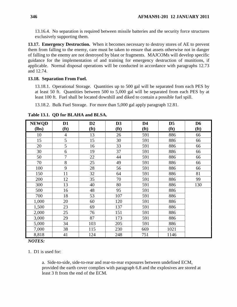
346 AFMAN91-201 12 JANUARY 2011
13.16.4. No separation is required between missile batteries and the security force structures
exclusively supporting them.
13.17. Emergency Destruction. When it becomes necessary to destroy stores of AE to prevent
them from falling to the enemy, care must be taken to ensure that assets otherwise not in danger
of falling to the enemy are not destroyed by blast or fragments. MAJCOMs will develop specific
guidance for the implementation of and training for emergency destruction of munitions, if
applicable. Normal disposal operations will be conducted in accordance with paragraphs 12.73
and 12.74.
13.18. Separation From Fuel.
13.18.1. Operational Storage. Quantities up to 500 gal will be separated from each PES by
at least 50 ft. Quantities between 500 to 5,000 gal will be separated from each PES by at
least 100 ft. Fuel shall be located downhill and diked to contain a possible fuel spill.
13.18.2. Bulk Fuel Storage. For more than 5,000 gal apply paragraph 12.81.
Table 13.1. QD for BLAHA and BLSA.
NEWQD
(lbs)
D1
(ft)
D2
(ft)
D3
(ft)
D4
(ft)
D5
(ft)
D6
(ft)
10 4 13 26 591 886 66
15 5 15 30 591 886 66
20 5 16 33 591 886 66
30 6 19 37 591 886 66
50 7 22 44 591 886 66
70 8 25 49 591 886 66
100 9 28 56 591 886 66
150 11 32 64 591 886 81
200 12 35 70 591 886 99
300 13 40 80 591 886 130
500 16 48 95 591 886
700 18 53 107 591 886
1,000 20 60 120 591 886
1,500 23 69 137 591 886
2,000 25 76 151 591 886
3,000 29 87 173 591 886
5,000 34 103 205 591 886
7,000 38 115 230 669 1021
8,818 41 124 248 751 1146
NOTES:
1. D1 is used for:
a. Side-to-side, side-to-rear and rear-to-rear exposures between undefined ECM,
provided the earth cover complies with paragraph 6.8 and the explosives are stored at
least 3 ft from the end of the ECM.
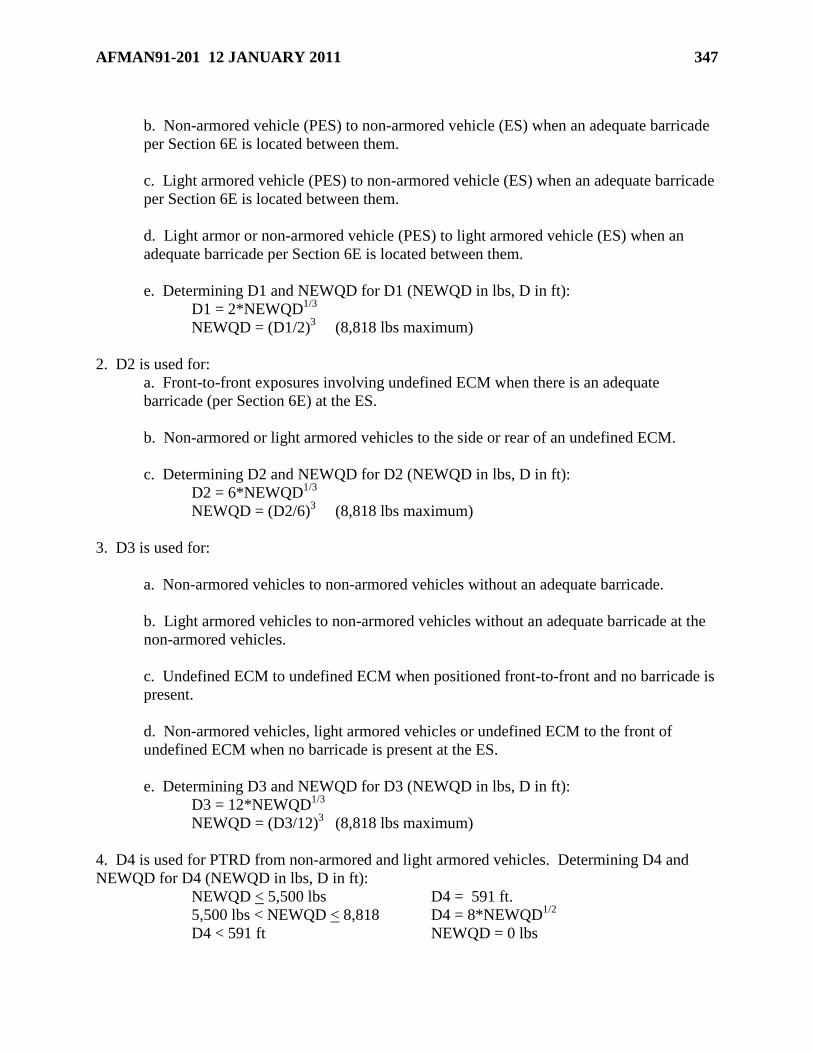
AFMAN91-201 12 JANUARY 2011 347
b. Non-armored vehicle (PES) to non-armored vehicle (ES) when an adequate barricade
per Section 6E is located between them.
c. Light armored vehicle (PES) to non-armored vehicle (ES) when an adequate barricade
per Section 6E is located between them.
d. Light armor or non-armored vehicle (PES) to light armored vehicle (ES) when an
adequate barricade per Section 6E is located between them.
e. Determining D1 and NEWQD for D1 (NEWQD in lbs, D in ft):
D1 = 2*NEWQD1/3
NEWQD = (D1/2)3 (8,818 lbs maximum)
2. D2 is used for:
a. Front-to-front exposures involving undefined ECM when there is an adequate
barricade (per Section 6E) at the ES.
b. Non-armored or light armored vehicles to the side or rear of an undefined ECM.
c. Determining D2 and NEWQD for D2 (NEWQD in lbs, D in ft):
D2 = 6*NEWQD1/3
NEWQD = (D2/6)3 (8,818 lbs maximum)
3. D3 is used for:
a. Non-armored vehicles to non-armored vehicles without an adequate barricade.
b. Light armored vehicles to non-armored vehicles without an adequate barricade at the
non-armored vehicles.
c. Undefined ECM to undefined ECM when positioned front-to-front and no barricade is
present.
d. Non-armored vehicles, light armored vehicles or undefined ECM to the front of
undefined ECM when no barricade is present at the ES.
e. Determining D3 and NEWQD for D3 (NEWQD in lbs, D in ft):
D3 = 12*NEWQD1/3
NEWQD = (D3/12)3 (8,818 lbs maximum)
4. D4 is used for PTRD from non-armored and light armored vehicles. Determining D4 and
NEWQD for D4 (NEWQD in lbs, D in ft):
NEWQD < 5,500 lbs D4 = 591 ft.
5,500 lbs < NEWQD < 8,818 D4 = 8*NEWQD1/2
D4 < 591 ft NEWQD = 0 lbs
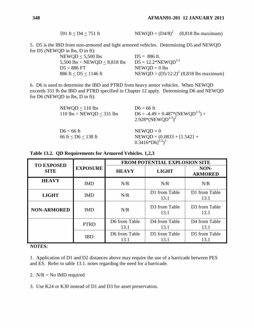
348 AFMAN91-201 12 JANUARY 2011
591 ft < D4 < 751 ft NEWQD = (D4/8)2 (8,818 lbs maximum)
5. D5 is the IBD from non-armored and light armored vehicles. Determining D5 and NEWQD
for D5 (NEWQD in lbs, D in ft):
NEWQD < 5,500 lbs D5 = 886 ft.
5,500 lbs < NEWQD < 8,818 lbs D5 = 12.2*NEWQD1/2
D5 < 886 FT NEWQD = 0 lbs
886 ft < D5 < 1146 ft NEWQD = (D5/12.2)2 (8,818 lbs maximum)
6. D6 is used to determine the IBD and PTRD from heavy armor vehicles. When NEWQD
exceeds 331 lb the IBD and PTRD specified in Chapter 12 apply. Determining D6 and NEWQD
for D6 (NEWQD in lbs, D in ft):
NEWQD < 110 lbs D6 = 66 ft
110 lbs < NEWQD < 331 lbs D6 = -4.49 + 0.487*(NEWQD1/3
) +
2.928*(NEWQD1/3
)2
D6 < 66 ft NEWQD = 0
66 ft < D6 < 138 ft NEWQD = (0.0833 + [1.5421 +
0.3416*D6]1/2
)3
Table 13.2. QD Requirements for Armored Vehicles. 1,2,3
TO EXPOSED
SITE EXPOSURE
FROM POTENTIAL EXPLOSION SITE
HEAVY LIGHT NON-
ARMORED
HEAVY
IMD N/R N/R N/R
LIGHT IMD N/R D1 from Table
13.1
D1 from Table
13.1
NON-ARMORED
IMD N/R D3 from Table
13.1
D3 from Table
13.1
PTRD D6 from Table
13.1
D4 from Table
13.1
D4 from Table
13.1
IBD D6 from Table
13.1
D5 from Table
13.1
D5 from Table
13.1
NOTES:
1. Application of D1 and D2 distances above may require the use of a barricade between PES
and ES. Refer to table 13.1. notes regarding the need for a barricade.
2. N/R = No IMD required
3. Use K24 or K30 instead of D1 and D3 for asset preservation.
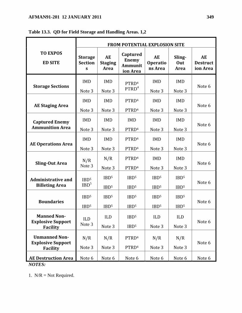
AFMAN91-201 12 JANUARY 2011 349
Table 13.3. QD for Field Storage and Handling Areas. 1,2
TO EXPOS
ED SITE
FROM POTENTIAL EXPLOSION SITE
Storage Section
s
AE Staging
Area
Captured Enemy
Ammunition Area
AE Operations Area
Sling-Out
Area
AE Destruction Area
Storage Sections IMD
Note 3
IMD
Note 3
PTRD4 PTRD
4
IMD
Note 3
IMD
Note 3 Note 6
AE Staging Area IMD
Note 3
IMD
Note 3
PTRD4
PTRD4
IMD
Note 3
IMD
Note 3 Note 6
Captured Enemy Ammunition Area
IMD
Note 3
IMD
Note 3
IMD
PTRD4
IMD
Note 3
IMD
Note 3 Note 6
AE Operations Area IMD
Note 3
IMD
Note 3
PTRD4
PTRD4
IMD
Note 3
IMD
Note 3 Note 6
Sling-Out Area N/R
Note 3
N/R
Note 3
PTRD4
PTRD4
IMD
Note 3
IMD
Note 3 Note 6
Administrative and Billeting Area
IBD5 IBD
5
IBD5
IBD5
IBD5
IBD5
IBD5
IBD5
IBD5
IBD5 Note 6
Boundaries IBD5
IBD5
IBD5
IBD5
IBD5
IBD5
IBD5
IBD5
IBD5
IBD5 Note 6
Manned Non-Explosive Support
Facility
ILD Note 3
ILD
Note 3
IBD5
IBD5
ILD
Note 3
ILD
Note 3 Note 6
Unmanned Non-Explosive Support
Facility
N/R
Note 3
N/R
Note 3
PTRD4
PTRD4
N/R
Note 3
N/R
Note 3 Note 6
AE Destruction Area Note 6 Note 6 Note 6 Note 6 Note 6 Note 6
NOTES:
1. N/R = Not Required.
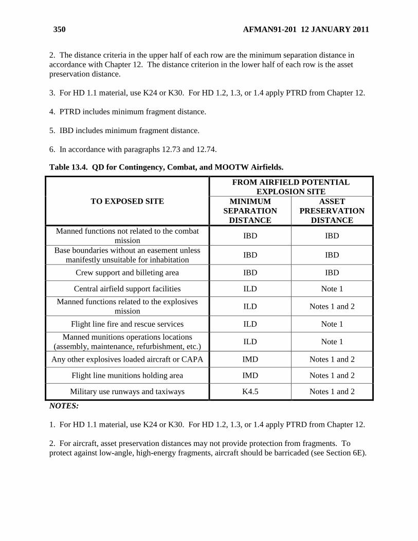
350 AFMAN91-201 12 JANUARY 2011
2. The distance criteria in the upper half of each row are the minimum separation distance in
accordance with Chapter 12. The distance criterion in the lower half of each row is the asset
preservation distance.
3. For HD 1.1 material, use K24 or K30. For HD 1.2, 1.3, or 1.4 apply PTRD from Chapter 12.
4. PTRD includes minimum fragment distance.
5. IBD includes minimum fragment distance.
6. In accordance with paragraphs 12.73 and 12.74.
Table 13.4. QD for Contingency, Combat, and MOOTW Airfields.
TO EXPOSED SITE
FROM AIRFIELD POTENTIAL
EXPLOSION SITE
MINIMUM
SEPARATION
DISTANCE
ASSET
PRESERVATION
DISTANCE
Manned functions not related to the combat
mission IBD IBD
Base boundaries without an easement unless
manifestly unsuitable for inhabitation IBD IBD
Crew support and billeting area IBD IBD
Central airfield support facilities ILD Note 1
Manned functions related to the explosives
mission ILD Notes 1 and 2
Flight line fire and rescue services ILD Note 1
Manned munitions operations locations
(assembly, maintenance, refurbishment, etc.) ILD Note 1
Any other explosives loaded aircraft or CAPA IMD Notes 1 and 2
Flight line munitions holding area IMD Notes 1 and 2
Military use runways and taxiways K4.5 Notes 1 and 2
NOTES:
1. For HD 1.1 material, use K24 or K30. For HD 1.2, 1.3, or 1.4 apply PTRD from Chapter 12.
2. For aircraft, asset preservation distances may not provide protection from fragments. To
protect against low-angle, high-energy fragments, aircraft should be barricaded (see Section 6E).
AFMAN91-201 12 JANUARY 2011 351
Chapter 14
EXPLOSIVES SITE PLANNING
Section 14A—Introduction
14.1. Purpose of Explosives Site Planning. Explosives site planning is a process used to
manage the risks associated with explosives activities to ensure the minimum risk to personnel,
equipment, and assets, while meeting mission requirements. Planning for the proper location and
construction of explosives facilities, and facilities exposed to explosives facilities, is a key
element of the explosives site planning process. This process also ensures that risks above those
normally accepted for explosives activities are identified and presented to the appropriate
commander for approval. The explosives site planning process is applicable to all day-to-day (to
include training and exercises), contingency, combat, and MOOTW activities, as well as wartime
planning.
14.2. Responsibilities for Explosives Site Planning. Safety, in coordination with civil
engineering, fire, health, security, and environmental agencies, is responsible for performing
explosives site planning.
Section 14B—Explosives Clear Zones
14.3. Explosives Clear Zones. The explosives clear zone is the area surrounding a PES which
is determined by the required IB separation. The IB separation will be based on the sited,
waivered, exempted, or actual explosives limits of the potential explosion site, whichever is
greatest.
14.4. Monitoring of Explosives Clear Zones. Safety and civil engineering will monitor and
control construction and facility utilization inside explosives clear zones. Management of
explosives safety clear zones is a cornerstone of the explosives site planning process.
14.5. Mapping Requirements for Explosives Clear Zones.
14.5.1. Explosives clear zones for all approved day-to-day and war plan explosives site plans
(ESP) will be reflected on the installation Comprehensive Plan Maps C-1, D-8, E-9 and M-3
(as applicable). For tiered siting, (see paragraph 14.20) only the largest explosives clear
zone need be shown, except on the D-8 which must show the explosives clear zones for all
tiers. Explosives clear zones must reflect the DDESB-, AFSC- or MAJCOM-approved net
explosives weight and IB distance.
14.5.2. The weapons safety manager will assist civil engineering in determining the
explosives clear zones required on appropriate base maps.
14.5.3. Explosives clear zones need not be changed on base maps when they are expanded
for a short-term (1 year or less) situation, such as for a waiver lasting less than a year.
14.6. Reduction or Re-designation of Explosives Clear Zones. When a permanent reduction
or re-designation of any explosives clear zone is required, a coordinated (installation safety, civil
engineering, and logistics) request letter is prepared and submitted to the host MAJCOM Safety
Office through the respective MAJCOM activity offices. Requests must be signed by the
352 AFMAN91-201 12 JANUARY 2011
installation commander and include justification for the reduction. To better evaluate the impact
if the reduction is not approved, include a clear zone map showing both the old and the proposed
clear zones. No actions will be taken to redraw base maps until DDESB approval is received.
MAJCOM approval is needed for complete removal of clear zone. MAJCOM will forward a
copy of the approval to AFSC/SEW.
Section 14C—Explosives Site Plans
14.7. Explosives Site Plans. Explosives Site Plans (ESPs) are a method to document the results
of the explosives site planning process. An ESP package consists of all the information
necessary to assess compliance with explosives safety standards (especially QD). Once
approved, the ESP identifies storage and operational limitations, and provides a tool for
managing risks associated with the storage or operating location.
14.8. Funding for Projects Requiring Explosives Site Plans. Prior to approval of an ESP,
expend only limited Air Force funds on the ESP project. ESP approval is covered in paragraph
14.15. All funds spent prior to approval may be placed at risk if explosives safety standards are
not followed properly. The investment could be lost if site plan approval is contingent on
changes or new facility requirements that were not considered or adequately addressed during
the ESP preparation and review process. It is strongly suggested that at least Preliminary ESP
approval (see paragraph 14.13.) be obtained before awarding a contract for new construction of
explosives facilities or non-explosives facilities within an explosives clear zone.
14.9. Situations Requiring Explosives Site Plans. ESPs will be developed and submitted for
review and approval for the following situations:
14.9.1. New construction of explosives facilities.
14.9.2. New construction of non-explosives facilities within an explosives clear zone.
14.9.3. Modification or change to the use of explosives facilities, as required per paragraph
14.11.
14.9.4. Modification or change to the use of non-explosives facilities within an explosives
clear zone, as required per paragraph 14.11.
14.9.5. Recurring training and exercise explosives activities which occur in fixed locations,
except as allowed in paragraph 14.10.9.
14.9.6. War plan explosives activities. War plan explosives activities are those that are
planned in response to an approved operational plan. They are only projections based on
possible or likely scenarios, and include planned operations at collocated operating bases
(COBs).
14.9.7. Contingency, combat, and MOOTW explosives activities, as required per Chapter
13.
14.10. Situations Not Requiring Explosives Site Plans. ESPs are not required for the
following situations:
14.10.1. Storage and associated HD 1.4S handling (see paragraph 12.29.3.).
14.10.2. Interchange yards limited to those operations described in paragraph 12.59.
AFMAN91-201 12 JANUARY 2011 353
14.10.3. Inspection stations where only the operations described in paragraph 12.58. are
performed.
14.10.4. Parking aircraft loaded with specific munitions (see paragraph 12.47., while the
aircraft is located in designated aircraft parking areas that meet airfield criteria. This
includes associated handling of these munitions, provided the quantity of munitions involved
in the operation is limited to a single aircraft load.
14.10.5. Hung ordnance areas, arm or de-arm areas, and hot pit refueling areas not used as
parking areas (see paragraph 12.44. and 12.45.), unless they are located in an explosives
clear zone. In that case, they will be sited as a non-explosives exposed site.
14.10.6. Licensed explosives storage locations, unless they are located in an explosives clear
zone. In that case, they will be sited as a non-explosives exposed site.
14.10.7. Explosives operations associated with licensed explosives storage locations.
14.10.8. Inert storage accessed by personnel related to the explosives mission.
14.10.9. Activation of simulators and smoke-producing devices in single or small quantities
when used in conjunction with exercises and training (to include readiness inspections). See
paragraph 7.26 for guidance.
14.10.10. Unmanned, non-explosives miscellaneous structures that have a QD requirement
of fifty feet or less do not require an ESP, even if new construction is involved.
14.11. Facility Modifications or Change in Use. Existing explosives facilities and exposed
facilities within explosives clear zones may require modification or change in use to meet
changing mission requirements. Such modifications and changes in use must be evaluated to
determine if they affect the application of explosives safety requirements as approved in the
original ESP.
14.11.1. A new ESP is required if the facility modification or change in use may require the
application of new or more stringent explosives criteria as follows:
14.11.1.1. Classification of the facility for QD purposes is changed (e.g., explosives
storage facility is changed to an operating location).
14.11.1.2. NEWQD is increased.
14.11.1.3. New HD is introduced.
14.11.1.4. Overall floor space is increased (to include vertical additions).
14.11.1.5. Additional personnel performing a different function are introduced.
14.11.1.6. Effectiveness of built-in safety features is compromised (e.g., opening is made
in a SDW).
14.11.1.7. The installation of a new lightning protection system (e.g., the complete
replacement of an existing system or replacing an integral system with a mast or catenary
system).
14.11.2. If the facility modification or change in use does not require the application of more
stringent QD criteria and is not covered by a waiver or exemption, a letter describing the
facility modification or change in use is required and will be submitted to the MAJCOM for
354 AFMAN91-201 12 JANUARY 2011
approval. Prior to approval, the MAJCOM will ensure the facility modification or change in
use does not affect the explosives safety criteria applied in the original ESP.
14.11.3. Any modification or change in use to a facility covered by a waiver or exemption to
this standard must be reviewed by AFSC/SEW. MAJCOM/SEW will submit a letter
thoroughly describing the facility modification or change in use. AFSC/SEW will provide
appropriate siting actions required.
14.11.4. Do not start construction on a project requiring an ESP until approval is granted by
the DDESB. For site plans covering day-to-day operations where no construction is involved,
do not start explosives operations or non-explosives operations within explosives clear zones
until the site plan is approved at MAJCOM level. The Combatant Commander may authorize
explosives operations or construction pending siting approval for operations in support of or
in expectation of actual MOOTW, contingency, and combat operations.
14.12. Explosives Site Plan Development and Installation-level Coordination.
14.12.1. The civil engineer or facility user notifies weapons safety as soon as a need is
identified to build, modify, or change the use of any explosives facility or non-explosives
facility located within an explosives clear zone. Weapons safety determines the need for an
ESP and solicits the information to prepare the request.
14.12.2. The civil engineer assists safety in development of the ESP by providing current
maps or drawings and technical facility design assistance. Also, the civil engineer supplies
facility design information such as construction, grounding, technical facility design
assistance, and lightning protection information.
14.12.3. Site for maximum weights based on actual separation distances or capacity for
storage locations; however, for other locations site for MEQ/operational limits.
14.12.4. Coordinate the ESP with civil engineering and the user. Coordinate with fire,
health, security, legal and environmental agencies, as appropriate.
14.12.5. Coordinate the ESP with bioenvironmental engineering if it involves biological and
chemical fillers, liquid propellants, toxic gases, sonic hazard areas, any form of
electromagnetic radiation, laser or other directed energy weapons (DEW) affecting health or
the environment on-base (including radioactive sources and microwave generators and
industrial x-ray). The MAJCOM will forward an information copy of the ESP to the AF
Medical Support Agency (AFMSA/SG3PB), 1400 Key Blvd, Suite 400, Arlington VA
22209.
14.12.6. When tenant facilities, including those of other services, are exposed, coordinate the
ESP with the tenant unit. For ESPs that expose host nation tenant facilities or areas, notify
the host nation commander of the exposure and obtain host nation approval as required by
international treaty or status of forces agreement.
14.12.7. In cases where the explosives clear zone encroaches onto adjacent government
agencies, such as another Air Force, or an Army, Navy or Marine installation, obtain written
acknowledgement from the exposed service component for inclusion with the ESP. (Note: It
will be up to the acknowledging agency to update their maps to reflect the explosives clear
zone for their future planning purposes.)
AFMAN91-201 12 JANUARY 2011 355
14.12.8. ESPs involving contractors must be reviewed and approved through the Defense
Plant Representative Office (DPRO), Administrative Contract Office (ACO) and the
Designated Acquisition Official’s (DAO) safety office prior to Air Force processing. Local
level shall coordinate with responsible contracting officer.
14.13. Explosives Site Plan Contents. ESPs will contain the information described in Section
14D. In some instances, a compressed timeline (such as that imposed by the design and build
process) may require contract award or site preparation activities (e.g., facility demolition,
grading or other site preparation) before all of the information required in Section 14D is
available. In these instances, request Preliminary ESP approval. Preliminary ESPs will include
the information required in Section 14D, except for facility construction drawings and any
required structural engineering analyses. Specifically address the action for which approval is
requested (e.g. contract award, facility demolition). Submit a request for Final ESP approval as
soon as the construction drawings and any required structural engineering analyses are
completed.
14.14. Explosives Site Plan Submission and MAJCOM and Air Force-level Coordination
Process.
14.14.1. The ESP originates at the installation level (See paragraph 14.26.). The primary
means for ESP origination is through the use of ASHS. MAJCOM/SEW will review the ESP
for accuracy and compliance with the standards in this Manual and applicable MAJCOM
supplements. MAJCOMs will then electronically submit the coordinated ESP to AFSC/SEW
(unless the ESP may be approved by the MAJCOM per paragraph 14.15). Include a
MAJCOM endorsement stating approval along with any changes, modifications or specific
precautionary measures considered necessary. After review by AFSC/SEW, the ESP is
endorsed and electronically submitted to the DDESB for approval. Reviewing agencies will
provide the ESP originator and previous review agency a copy of comments or changes made
which affect the original intent of the ESP. Any change affecting the content of the unit’s
ASHS database would require changes made at the unit.
14.14.2. Air Force Host to Tenant Relationships. ESPs for tenant units will be sent
through host installation and tenant command channels. In cases where the host violates
ESQD to a tenant facility, the host MAJCOM will obtain coordination from the tenant
MAJCOM before processing the ESP. Where no violation exists, provide an information
copy of the ESP to the tenant MAJCOM when processing to AFSC/SEW. If required by the
tenant MAJCOM, the ESP must meet the requirements of the tenant MAJCOM supplement
to this Manual.
14.14.3. Inter-service Host to Tenant Relationships.
14.14.3.1. When an Air Force unit is tenant on an Army, Navy or Marine installation,
request ESP approval through that service. The ESP must meet the QD requirements of
this Manual in addition to all host agency criteria. Submit an information copy of the
ESP request through the MAJCOM to AFSC/SEW.
14.14.3.2. Tenant Army, Navy or Marine units forward ESP requests through Air Force
host installation channels. Air Force host will assist tenant units in preparing the ESP. In
cases where the Air Force host violates ESQD to a tenant facility, the host MAJCOM will
obtain coordination from the tenant MAJCOM equivalent before processing the ESP.

356 AFMAN91-201 12 JANUARY 2011
Where no violation exists, provide an information copy of the ESP to the tenant
MAJCOM equivalent when processing to AFSC/SEW.
14.14.3.3. AFSC/SEW will coordinate with the applicable service component before
processing the ESP. In cases where the Air Force host violates ESQD to a tenant facility,
AFSC/SEW will obtain coordination from the applicable service component before
processing the ESP. Where no violation exists, an information copy of the ESP will be
sent to the applicable service component when processing for final approval.
14.14.4. AFSC/SEW will coordinate requests for ESP approval with the applicable service
component if an Air Force explosives clear zone encroaches onto an adjacent Air Force,
Army, Navy or Marine installation.
14.14.5. The installation or MAJCOM may request expeditious AFSC/SEW processing of
an ESP with the exception of an ESP requiring SAF/IE acceptance of risk or SECAF
approval for new construction. Requests for expeditious processing of an ESP will include
the information required in paragraph 14.22.19. MAJCOM/SE must endorse an installation
request for expeditious processing for AFSC/SEW to act on the request.
14.15. Explosives Site Plan Approval.
14.15.1. Except as authorized in paragraph 14.15.2, ESPs will be approved as follows:
14.15.1.1. Day-to-day ESPs will be approved by DDESB, unless they contain a waiver
or exemption. Day-to-day ESPs with waivers or exemptions will be submitted as Hybrid
Safety Submissions (HSS) to the DDESB for final approval after approval of the waiver
or exemption in accordance with Section 1B. Do not start new construction until
authorized by the approved ESP. (Note: If included in the ESP request, Preliminary ESP
approval may authorize some construction planning activities to begin. See paragraph
14.13.) Do not commence explosives operations or events unless authorized by an
approved operational waiver in accordance with paragraph 1.5. Operational waiver
documentation requirements prescribed in paragraph 1.5.4 may be addressed in the ESP
submission to the MAJCOM and AFSC/SEW. Once the ESP is reviewed by AFSC, the
ESP is transmitted to the greatest extent possible by electronic means to the DDESB or
the MAJCOM is notified of additional information needed to gain DDESB approval. If
additional information is needed to complete the ESP package, it should be provided
within 45 days of AFSC initial review comments or notification to AFSC from the
MAJCOM with a status of delay and estimated response date. If continued delay of
gathering additional information is encountered, AFSC will return the ESP as
disapproved, with a detailed explanation of the reason for disapproval. At this time, the
operational waiver authorization for operations to commence is invalidated. The entire
ESP may be resubmitted under a new control number once all criteria is met and included
in the ESP submission.
14.15.1.2. Contingency, combat, and MOOTW ESPs will be approved as required per
Chapter 13, unless they involve new construction. Contingency, combat, and MOOTW
ESPs involving new construction will be approved by the DDESB, unless they contain
waivers or exemptions. Contingency, combat, and MOOTW ESPs involving new
construction with waivers or exemptions will be submitted as HSS to the DDESB for
final approval after approval of the waiver or exemption in accordance with Section 1B.
AFMAN91-201 12 JANUARY 2011 357
The Combatant Commander may authorize new construction to begin in support of or in
expectation of actual contingency, combat, and MOOTW operations.
14.15.1.3. War plan ESPs will be approved by the MAJCOM/CC/CV, unless they
involve new construction; MAJCOM will provide a copy of the ESP to AFSC/SEW.
War plan ESPs involving new construction will be approved by the DDESB, unless they
contain waivers or exemptions. War plan ESPs involving new construction with waivers
or exemptions will be submitted as HSS to the DDESB for final approval after approval
of the waiver or exemption in accordance with Section 1B. Do not start construction until
authorized by the approved ESP. (Note: If included in the ESP request, Preliminary ESP
approval may authorize some construction activities to begin. See paragraph 14.13.)
Combined day-to-day and war plan ESPs (e.g. using tiered siting) will be approved
according to paragraph 14.15.1.1.
14.15.2. Approval levels for unique situations are as follows:
14.15.2.1. ESPs for training and exercise areas using flares, simulators, and smoke
producing devices (HD 1.2.2, 1.3 and 1.4 only), and not within an established clear zone,
will be approved by the MAJCOM. This applies to recurring training locations and not to
exercise support activities that move each time in accordance with exercise scenarios.
Required separation distances will be documented per paragraph 7.26. for exercise
support activities that do not have a fixed location.
14.15.2.2. ESPs for installation of WSVs in HASs with previously approved ESPs will
be approved by the MAJCOM.
14.15.2.3. ESPs for Contractor Owned Contractor Operated (COCO) facilities on non-
government land will be approved by the Procuring Contract Officer (PCO) for Air Force
contracts involving explosives or ammunition. ESPs are prepared and submitted by the
contractor. These ESPs need not be forwarded to either AFMC, AFSC, or the DDESB.
The Defense Contract Management Agency evaluates the ESP and provides approval or
disapproval recommendations to the PCO.
14.15.2.4. ESPs for Government Owned Contractor Operated (GOCO) facilities and
COCO facilities on government land will be approved by the DDESB. Waivers and
exemptions will be approved by the responsible PCO and Air Force command level as
prescribed in chapter 1.
14.15.2.5. ESPs for non-DoD explosives activities on Air Force installations will be
approved by the DDESB (see paragraph 14.17).
14.16. Maintenance of Approved Explosives Site Plans. Approved ESPs (including the
approval letter) will be maintained by the installation safety office and using organization.
Section 14D—Explosives Site Plan Requirements
14.17. Explosives Site Plans for Non-DoD Explosives Activities on Air Force Installations.
14.17.1. ESPs for non-DoD explosives activities on Air Force installations will include a
risk assessment for all exposed government personnel, equipment, and assets (within or
outside the explosives clear zone) and documented risk acceptance by the responsible
commander. The responsible commander must consider the possible impact to current
358 AFMAN91-201 12 JANUARY 2011
and future DoD mission requirements in the event of a mishap. Non-DoD user insurance
coverage for government equipment and assets will not, by itself, be adequate
justification for exposure to unacceptable risk.
14.17.2. ESPs for non-DoD explosives activities on Air Force installations will either be
prepared in accordance with the requirements of this section, or will be ―foot print‖ only
ESPs. Foot print ESPs will contain only the information necessary to determine the
explosives clear zone (i.e., building design, LPS, etc., will not be included unless it is used to
determine the explosives clear zone).
14.17.3. ESP approval alone does not authorize the conduct of non-DoD explosives
activities on Air Force installations (see paragraph 12.88.).
14.17.4. See paragraph 12.88. for QD criteria for non-DoD explosives activities on Air
Force installations, and paragraph 1.9 for guidance on exceptions to this Manual.
14.18. Siting a Non-Explosives Exposed Site. For new construction, modification, or change
in use of non-explosives facilities within an explosives clear zone it is acceptable to submit an
ESP for the non-explosives facilities. These ESPs will comply with all applicable requirements
of this section and include QD evaluations for all PESs within the evaluation zone. See
paragraph 14.24.7., Table 14.1. and Figure 14.1.
14.19. Explosives Site Plans Involving Exceptions. ESPs involving exceptions to this Manual
will include the information required per Section 1B.
14.20. Tiered Explosives Site Plans. Tiered ESPs may be useful when the NEWQD of a PES
varies because of operational requirements (e.g., day-to-day, exercise, war plan, contingency,
combat, and MOOTW). It may also be useful when it is not practical on a day-to-day basis to
meet the required QD separation from a PES to all ESs for the largest possible NEWQD. Under
the tiered ESP concept, the responsible commander may take management actions (e.g., removal
of personnel or equipment, re-designation of exposed sites) before introducing explosives or
increasing the NEWQD of a PES.
14.20.1. To prepare tiered ESPs, determine the NEWQD required for each type of activity at
the PES and the QD separation required to each ES for each NEWQD. In instances where
the required QD separation cannot be met at a given NEWQD, determine if management
actions may be taken to meet the required QD separation. If the required QD separation
cannot be met even with management actions, process a waiver or exemption in accordance
with Section 1B.
14.20.2. Prepare a management plan to document management actions required for each tier
of the ESP. This management plan may be implemented as a base operations plan, operating
instruction, agreement, supplement or other appropriate publication. The management plan
must specify:
14.20.2.1. Description of each management action required.
14.20.2.2. Conditions under which each management action will be directed and when
they will take place.
14.20.2.3. The organization responsible for implementing each management action.
AFMAN91-201 12 JANUARY 2011 359
14.20.2.4. Requirement for periodic review of the management plan to ensure continued
viability of the planned management actions.
14.20.3. Tiered ESPs will:
14.20.3.1. Include an AF Form 943,Explosives Site Plan for each tier, and assign a
separate ESP action number to each tier.
14.20.3.2. Reference the document which implements the management plan required in
paragraph 14.20.2. It is not necessary to include a copy of this document.
14.21. Components of the Explosives Site Plan. ESPs must include all the information needed
for the reviewer to determine if the explosives safety requirements of this Manual are being met.
Although the exact contents of an ESP may vary depending on the activity to be sited, ESPs
generally include a transmittal letter, an AF Form 943, a site location map, and various
attachments. For some ESPs, a transmittal letter containing pertinent information and a map may
be all that is necessary. Other ESPs may require documentation such as detailed drawings,
engineering analyses, risk assessments, commanders’ risk acceptances, etc, in order to verify
compliance with explosives safety requirements. See paragraph 14.26.
14.22. Transmittal Letter.
14.22.1. The transmittal letter is important for getting an ESP successfully reviewed and
approved. Generally, all aspects of the siting should be explained; attempt to answer any
questions before it is raised. Consider that personnel reviewing the ESP may not be familiar
with the base or operation, including unique terminology, and do not know the mission or
specific circumstances. If the AF Form 943 contains a modification to the ASHS generated
quantity-distance, explain the change in the transmittal letter. A sample transmittal letter is
provided in Attachment 2.
14.22.2. Include the ESP action number in the subject line of the memorandum. ESP action
numbers are developed as follows:
14.22.2.1. The requesting MAJCOM designation, followed by the tenant MAJCOM
designation, if appropriate. Examples: USAFE, or AFMC-ACC.
14.22.2.2. The installation where the PES is located. Examples: Hill, Ramstein, or
Logan.
14.22.2.3. Calendar year designation. Examples: 04, or 05.
14.22.2.4. An (S) identifier followed by a sequence number. Examples: S26, or S39.
Number each request sequentially for each calendar year. For example, the first ESP for
the calendar year would be S1. Canceled requests will not affect the number of
subsequent requests. For example, if USAFE-Ramstein-04-S10 were canceled, the next
ESP submitted for Ramstein AB in 2004 would be S11.
14.22.2.5. If the ESP involves QD exceptions, include the statement, ―WITH
EXCEPTIONS‖ immediately following the ESP action number. Example: ACC-
Barksdale-04-S33, WITH EXCEPTIONS. If the ESP involves only compensatory
measures that avoid all QD exceptions, include the statement, ―WITH
COMPENSATORY MEASURES‖ immediately following the ESP action number.
360 AFMAN91-201 12 JANUARY 2011
14.22.2.5.1. Units will develop a means to assure continued implementation of
compensatory measures per MAJCOM direction.
14.22.2.6. If the transmittal letter is for more than one ESP, include the ESP action
number for each ESP. Examples: PACAF-Hickam-04-S5, S6, and S10, or AMC-Scott-
05-S20 through S34.
14.22.3. Begin the letter by explaining the purpose of the submission. Example: ―Request
routine processing for subject site plan for preliminary approval.‖ Identify whether the ESP
supports day-to-day operations, war plan operations, day-to-day and war plan operations, or
MOOTW, contingency, and combat operations. Identify if preliminary or final approval is
being requested. If new construction is involved, include this statement in the subject line:
―Involving new Construction.‖ This ensures reviewing and approval authorities correctly
prioritize the submission request for review.
14.22.4. State the reason(s) for the request. Examples: ―to construct a new maintenance and
inspection facility,‖ or ―to increase the NEWQD at an existing above ground magazine.‖
Clearly identify whether new construction is being requested; expeditious and new
construction ESPs will receive priority processing.
14.22.5. If the ESP replaces an existing ESP include a cancellation statement. Example:
―The modification to this facility cancels ESP AFMC-Hill-02-S7.‖
14.22.6. State whether or not all explosives safety criteria will be met. If there are waivers
or exemptions, provide a unique exception identification tracking number for each waiver or
exemption. This number is developed using the format as described in paragraphs 14.22.2.1.
through 14.22.2.5., with the following modifications:
14.22.6.1. Use the identifier (W) for waivers or (E) for exemptions instead of (S) for the
identification tracking number in Column 10 of the AF Form 943 for the applicable
exposure. This unique identification number will be based on the approval level,
installation, and calendar year. Each installation will use their own numbering
sequence. For example, use ACC-Hill-05-W01 as the first MAJCOM-level waiver
identification number at Hill AFB for calendar year 2005. Use 388FW-Hill-05-W01 for
the first wing-level waiver identification number. Subsequent site plan submissions with
QD exceptions within the same calendar year would use the next available identification
number at that installation for the type of exception required. For example, the next
MAJCOM-level waiver identification number at Hill AFB would be ACC-Hill-05-W02
while the first MAJCOM-level exemption would use ACC-Hill-05-E01. This method
will allow accurate tracking of exceptions based on the approval level, installation and
calendar year. Include superseded waiver or exemption identification numbers if
applicable.
14.22.7. If the ESP has any unique characteristics, explain what criteria is being applied and
the basis for the application.
14.22.8. Describe compensatory measures if they are necessary to meet QD standards. The
responsible commander must sign ESPs containing compensatory measures.
14.22.8.1. Units will develop a means to assure continued implementation of
compensatory measures per MAJCOM direction.
AFMAN91-201 12 JANUARY 2011 361
14.22.9. For ESPs involving new construction, include the project identification and
Programming, Design, and Construction (PDC) number.
14.22.10. Discuss any future plans that may impact this siting. State that the Base Facilities
Board has reconciled this particular site plan with the base comprehensive plan. Provide
meeting minutes, dated reference or written record of reconciliation.
14.22.11. Explain the format being used to record QD evaluation. Example: ―The attached
AF Form 943 and map show all exposures and required separations.‖
14.22.12. Provide a narrative description of the relevant explosives safety aspects of the
facility design.
14.22.12.1. If the facility includes an LPS, state that it meets all design requirements of
this Manual, NFPA 780, AFI 32-1065, and attach LPS drawings. For PESs, if the facility
does not include an LPS, state what exception is being applied per paragraph 5.25.,
address any requirements relevant to that exception, and attach the commander’s risk
acceptance if required.
14.22.12.2. If protective construction features not previously approved by the DDESB
are to be used (e.g., personnel shields, blast-resistant construction), a structural
engineering analysis and construction drawings must be attached (see paragraph 14.25.3).
Provide a summary of the results of the structural engineering analysis.
14.22.12.3. Describe how compliance with the glass panel design requirements of
Section 5B will be met. Attach a glass breakage risk assessment if required.
14.22.12.4. Describe results of EMR survey.
14.22.12.5. Describe unique safety aspects of the facility design such as the presence of
hazardous locations, use of conductive floors, etc.
14.22.12.6. If the facility design is a standard design that the DDESB has previously
reviewed and declared acceptable, construction drawings do not need to be submitted.
Identify the drawing number and the source of previous DDESB approval (e.g., DDESB
TP 15, Approved Protective Construction). HASs may be referred to by type (e.g., 3rd
GEN, Korean TAB VEE). Contact MAJCOM/SEW if definitive drawing numbers are
unknown. Describe any planned deviations from the standard design for purposes of
local site adaptation (e.g., addition of gunite cover to an ECM to protect from erosion);
do not make changes to standard designs that affect the explosives safety characteristics
of the facility.
14.22.13. For tiered ESPs, identify the management plan implementation document.
14.22.14. Describe the evaluation zone used. State if the evaluation zone does not exceed
the IB distance, or if there are no PESs in the evaluation zone.
14.22.15. State if a commanders authorized risk acceptance option is being applied and the
derivative paragraph/table/note option allowing the commanders risk acceptance.
14.22.16. Identify and explain the purpose of all attachments.
14.22.17. Address compliance with ESP coordination requirements (e.g., notification or
coordination with host nation officials, discussions with tenant units, etc.).
362 AFMAN91-201 12 JANUARY 2011
14.22.18. Staff agency point of contact in the event clarification is required.
14.22.19. If expeditious processing is being requested, include the following:
14.22.19.1. On the subject line of the memorandum state: ―Request for EXPEDITIOUS
processing of Explosives Site Plan (ESP) AFSPC-Vandenberg-04-S2.‖
14.22.19.2. Explain the reasons why expeditious processing is necessary. These reasons
must show sufficient mission impact to warrant the expeditious processing, or the ESP
will be reviewed according to the routine processing procedures.
14.22.19.3. Date when approval is needed and why it is needed by that date. Example:
―Approval is required by 15 Jun 05 to support planned contract award for new
construction.‖ Require MAJCOM/SE approval and signature.
14.23. AF Form 943. AF Form 943 is used to provide PES and ES information and to validate
required QD separation. Prepare a separate AF Form 943 for each PES (or ES in the case of an
ES ESP) to be sited. See paragraph 14.27 for alternative formats to the AF Form 943.
Instructions for completing AF Form 943 are provided in Figure 14.2. A sample AF Form 943 is
provided in Figure 14.3. Include the following information on the AF Form 943:
14.23.1. ESP action number (see paragraph 14.22.2).
14.23.2. Location of the PES or ES being sited. If the location is not a military installation,
list civilian or commercial address.
14.23.3. For explosives locations, identify all ESs and PESs within the IB distance, and all
PESs within the evaluation zone (EZ) if it is larger than the IB distance. For ESPs with an IB
distance less than 100 ft, ensure exposures requiring a minimum separation distance (e.g.,
100 ft for parking areas exclusively supporting the PES) are identified. For non-explosive
locations, identify all PESs within the EZ. For some non-explosive locations, it may not be
necessary to identify all PESs; for example, unmanned miscellaneous structures requiring 50
feet separation from any PES can be sited by merely identifying the nearest PES.
14.23.4. The EZ is based on the QD type of the ES (e.g., Operating Location, CAPA), and
the largest NEWQD PES on the installation. To determine the size of the EZ, when a K
Factor is required use the largest HD 1.1 NEWQD authorized in a single PES on the
installation or within the established clear zone (maximum of 500,000 pounds); see Table
14.1. For other HDs, use the minimum prescribed distances found in the appropriate QD
tables. See Figure 14.1. for examples of EZs.
14.23.5. For all PESs and ESs, provide the following:
14.23.5.1. Assigned CE building number or other identifier. Examples: Bldg 123, or
F123.
14.23.5.2. Applicable Table 12.(X) description. Examples: ECM, or Related Facility.
Identify the presence of barricades if they affect the QD required.
14.23.5.3. Primary operation normally expected at the facility. Examples: shipping and
receiving, maintenance and inspection, or bomb build-up. If facility type determines QD
criteria applied, include definition of building such as Korean TAB VEE, 3rd
Gen HAS,
26x60 igloo, 26x40 igloo, etc. Show definitive drawing numbers when available.
AFMAN91-201 12 JANUARY 2011 363
14.23.5.4. The organization whose assets or people will be in the facility. Include the
MAJCOM, Wing, Squadron, and show unit designations by number and alpha
designation. Include the branch of service if other than the Air Force. Example:
USAFE-52FW.
14.23.5.5. Total number of people (M for Military or DoD Civilian, C for Non-DoD
Civilian, DC for Defense Contractors, and FN for Foreign Nationals) normally
assigned to the location. Consider the number of persons present during exercises. Do
not include casuals such as inspectors or quality control evaluators. Include a breakdown
by room or bay, when appropriate. Do not show people assigned to explosives storage
locations, AECPAs, or CAPAs.
14.23.6. For all PES, provide the NEWQD for all HDs (HD 1.2.3, 1.5 and 1.6 may be
omitted unless quantities will be present). Include MCE for HD 1.2.1. Include LSRN and
parenthetical fragment distance for HD 1.2.3. If no LSRN is specified, use the NEWQD of
the single round. If no NEWQD is provided, contact AFSC/SEW. For HD 1.4 show
―Capacity‖ or ―Op Limit.‖ If no explosives in a particular HD will be present, type ―None.‖
For multiple room facilities, show values for each room where explosives will be present.
Where IM is not provided between rooms or cubicles, show overall values for the facility. If
explosives are unpackaged see Section 3C. The explosive authorization must always show
the sited, waived, or exempted weights, whichever is greater.
14.23.7. It is important to ensure facilities or locations being sited, whether explosive or
non-explosive, within the IBD and EZ comply with QD requirements. This is accomplished
by conducting a paired relationship evaluation. A facility or location where explosives will
be present must be evaluated as both a PES and an ES. This is a two-way evaluation
between the pair and the most restrictive distance between the pair is documented. A non-
explosive ES is a one-way evaluation from surrounding PESs to the ES.
14.23.8. Identify the actual separation between each pair.
14.23.9. Using applicable Chapter 12 Table and applicable notes, identify the most
restrictive (greatest) separation distance required between each pair for each HD, and the
appropriate K-factor, minimum distance or rule used to determine this distance.
14.23.10. For each instance where the required separation is greater than the actual
separation, provide the exception identification number (see paragraph 14.22.6).
14.23.11. For ESPs with waivers or exemptions, include the following:
14.23.11.1. Indicate the effect a maximum credible event at the PES would have on the
unit mission, or other supported agencies (see Chapter 2).
14.23.11.2. Describe any corrective actions, compensatory measures, and controls to
achieve safety during operations if the ESP is approved. State whether corrective action
can or cannot be done locally with available funds or other resources. If there is no
planned construction or other corrective actions, explain why. Show planned or
programmed (funded and unfunded) actions to eliminate exceptions. Such action might
include recommendations to higher headquarters, assigning priorities, funding revisions
to standard facilities, etc. If there are other local projects underway that involve funding,
show the following: construction priority assigned, Military Construction Program
364 AFMAN91-201 12 JANUARY 2011
(MCP) item number and fiscal year for construction. Include any operational controls
necessary.
14.23.11.3. Give the reason for the request. Describe the impact if the requested action
is not approved.
14.23.12. If exceptions are involved, or if compensatory measures are used to prevent an
exception, include approvals from the appropriate agencies and the responsible commander.
For exceptions, the responsible commander's signature shows that the request is needed for
the mission and that the risks are acceptable for strategic or compelling reasons. For
compensatory measures, the responsible commander’s signature shows that the
compensatory measures are acceptable and will be enforced.
14.24. Site Location Map. A sample site location map is provided in Figure 14.4.
14.24.1. Submit a map which clearly shows all the PESs and ESs relevant to the ESP.
14.24.2. Use a 1‖= 400’ (or similar metric) scale. To enhance clarity or show precise
measurements, a larger (1‖=200’ or 100’) scaled map may be used. To properly reflect
certain distance and structure relationships within the area surrounding the project, a smaller
scaled map may be used. Provide the scale on the map. Express all distances in feet, if
feasible. An ASHS-generated map is acceptable.
14.24.3. Details such as the specific points of measurement, actual and required distance,
and NEWQDs are encouraged.
14.24.4. When there is reasonable doubt about the accuracy of the mapped location, it is the
responsibility of all participants in the explosives site planning process to define a locally
acceptable method for determining the measurement accuracy required between the PES-ES
locations.
14.24.5. If the base boundary is not shown on the map, the transmittal letter must certify the
relationship of the explosives clear zone to the base boundary for ESPs.
14.24.6. When siting a PES, show all exposed sites within IBD of the PES. When there is an
evaluation zone larger than the IB clear zone of the PES being sited show the evaluation zone
(with dashed line) and the PESs in it.
14.24.7. When siting an ES, show the evaluation zone (dashed line) and all PESs in the
evaluation zone.
14.24.8. Use color coding to simplify and speed the review process. Identify the PESs in red
and ESs in green. Highlight the clear zone lines in red.
14.24.9. Include ESP action number, title and scale.
14.24.10. Show topographic contours or features, such as natural barricades (i.e. dense
forest) or hills, if they are pertinent to the application of QD.
14.24.11. When siting multiple PESs show the IBD clear zone for each PES. Show a
blended clear zone if it provides additional clarity.
14.25. Construction Drawings and Structural Engineering Analyses.
AFMAN91-201 12 JANUARY 2011 365
14.25.1. For facilities not being constructed in accordance with a previously DDESB-
approved design (see paragraph 14.22.12.5), construction drawings showing applicable
safety and protective features are required . These drawings must show, as a minimum, the
following information:
14.25.1.1. Floor layout, roofs, windows, and general materials used.
14.25.1.2. Substantial dividing walls, vent walls, firewalls, operational shields and
barricades.
14.25.1.3. Exits and fire protection system installations.
14.25.1.4. Types of floor finish, electrical systems and equipment, and ventilation
systems and equipment.
14.25.1.5. Hazardous waste disposal systems
14.25.1.6. LPS and static grounding systems. See paragraph 14.25.2 for detailed LPS
drawing requirements.
14.25.1.7. Process equipment.
14.25.1.8. Auxiliary support structures.
14.25.1.9. Drawings, specifications, rationale and base security manager approval of
physical security designs when the design is different than standard construction methods
used for explosive facilities.
14.25.1.10. Do not submit drawings (e.g., for landscapes or pavements) that are not
relevant to QD or safety protective factors.
14.25.2. LPS drawings must include:
14.25.2.1. Elements of the lightning protection system, such as air terminals, masts,
overhead wires, grounding electrode system and a description of the surge protection.
14.25.2.2. Top, front, side, and additional views as necessary depicting the dimensions
(spacing and height) between design elements. Front and side elevations depicting air
terminals and the 100-foot radius (200 feet diameter) rolling sphere zone of protection is
suggested to facilitate the site plan review process.
14.25.3. For protective construction features not previously approved by the DDESB,
provide construction drawings and a structural engineering analysis including:
14.25.3.1. Statement of the design objectives in terms of protection categories to be
obtained (see DDESB TP 15, Approved Protective Construction).
14.25.3.2. The explosives quantities involved.
14.25.3.3. The design loads applied.
14.25.3.4. Any material properties and structural behavior assumptions made.
14.25.3.5. References and the sources of methods used.
14.25.3.6. Qualifications of the preparer. Only engineers who are experienced in the
field of structural dynamics and who use design procedures accepted by professionals, in
that field, may design explosion resistant facilities.
366 AFMAN91-201 12 JANUARY 2011
14.26. Automated Explosives Site Planning. ASHS is the preferred method of ESP
development of the AF Form 943 and associated map. To the greatest extent possible, ASHS
will be used for ESP creation. In the event an ASHS database is not available for the location
requiring an ESP submission, manual means of ESP development may be used but must be
electronically submitted to the greatest extent possible.
Section 14E—Deleted
14.27. Alternative AF Form 943 Formats. In some instances, modifications to the AF Form
943, or a substitute format in place of the AF Form 943, may be acceptable. Provide a
description of the proposed alternative format, and justification for its use, to the MAJCOM for
approval. MAJCOM will coordinate with AFSC/SEW prior to granting approval. Any
alternative format used must still provide the information required in paragraph 14.23.
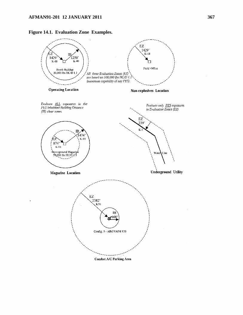
AFMAN91-201 12 JANUARY 2011 367
Figure 14.1. Evaluation Zone Examples.
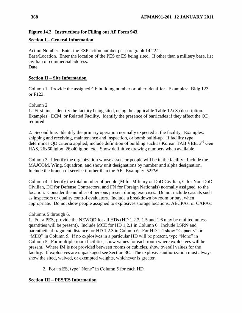
368 AFMAN91-201 12 JANUARY 2011
Figure 14.2. Instructions for Filling out AF Form 943.
Section I – General Information
Action Number. Enter the ESP action number per paragraph 14.22.2.
Base/Location. Enter the location of the PES or ES being sited. If other than a military base, list
civilian or commercial address.
Date
Section II – Site Information
Column 1. Provide the assigned CE building number or other identifier. Examples: Bldg 123,
or F123.
Column 2.
1. First line: Identify the facility being sited, using the applicable Table 12.(X) description.
Examples: ECM, or Related Facility. Identify the presence of barricades if they affect the QD
required.
2. Second line: Identify the primary operation normally expected at the facility. Examples:
shipping and receiving, maintenance and inspection, or bomb build-up. If facility type
determines QD criteria applied, include definition of building such as Korean TAB VEE, 3rd
Gen
HAS, 26x60 igloo, 26x40 igloo, etc. Show definitive drawing numbers when available.
Column 3. Identify the organization whose assets or people will be in the facility. Include the
MAJCOM, Wing, Squadron, and show unit designations by number and alpha designation.
Include the branch of service if other than the AF. Example: 52FW.
Column 4. Identify the total number of people (M for Military or DoD Civilian, C for Non-DoD
Civilian, DC for Defense Contractors, and FN for Foreign Nationals) normally assigned to the
location. Consider the number of persons present during exercises. Do not include casuals such
as inspectors or quality control evaluators. Include a breakdown by room or bay, when
appropriate. Do not show people assigned to explosives storage locations, AECPAs, or CAPAs.
Columns 5 through 6.
1. For a PES, provide the NEWQD for all HDs (HD 1.2.3, 1.5 and 1.6 may be omitted unless
quantities will be present). Include MCE for HD 1.2.1 in Column 6. Include LSRN and
parenthetical fragment distance for HD 1.2.3 in Column 6. For HD 1.4 show ―Capacity‖ or
―MEQ‖ in Column 5. If no explosives in a particular HD will be present, type ―None‖ in
Column 5. For multiple room facilities, show values for each room where explosives will be
present. Where IM is not provided between rooms or cubicles, show overall values for the
facility. If explosives are unpackaged see Section 3C. The explosive authorization must always
show the sited, waived, or exempted weights, whichever is greater.
2. For an ES, type ―None‖ in Column 5 for each HD.
Section III – PES/ES Information
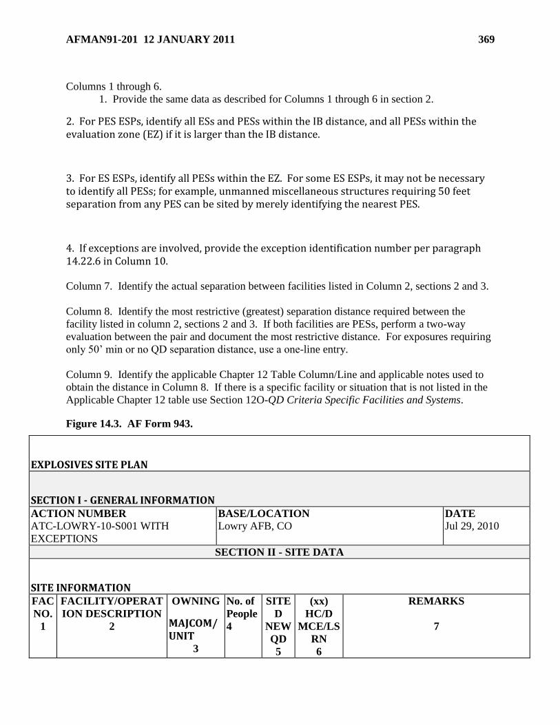
AFMAN91-201 12 JANUARY 2011 369
Columns 1 through 6.
1. Provide the same data as described for Columns 1 through 6 in section 2.
2. For PES ESPs, identify all ESs and PESs within the IB distance, and all PESs within the evaluation zone (EZ) if it is larger than the IB distance.
3. For ES ESPs, identify all PESs within the EZ. For some ES ESPs, it may not be necessary to identify all PESs; for example, unmanned miscellaneous structures requiring 50 feet separation from any PES can be sited by merely identifying the nearest PES.
4. If exceptions are involved, provide the exception identification number per paragraph 14.22.6 in Column 10.
Column 7. Identify the actual separation between facilities listed in Column 2, sections 2 and 3.
Column 8. Identify the most restrictive (greatest) separation distance required between the
facility listed in column 2, sections 2 and 3. If both facilities are PESs, perform a two-way
evaluation between the pair and document the most restrictive distance. For exposures requiring
only 50’ min or no QD separation distance, use a one-line entry.
Column 9. Identify the applicable Chapter 12 Table Column/Line and applicable notes used to
obtain the distance in Column 8. If there is a specific facility or situation that is not listed in the
Applicable Chapter 12 table use Section 12O-QD Criteria Specific Facilities and Systems.
Figure 14.3. AF Form 943.
EXPLOSIVES SITE PLAN
SECTION I - GENERAL INFORMATION ACTION NUMBER BASE/LOCATION DATE
ATC-LOWRY-10-S001 WITH
EXCEPTIONS
Lowry AFB, CO Jul 29, 2010
SECTION II - SITE DATA
SITE INFORMATION FAC
NO.
1
FACILITY/OPERAT
ION DESCRIPTION
2
OWNING
MAJCOM/UNIT
3
No. of
People
4
SITE
D
NEW
QD
5
(xx)
HC/D
MCE/LS
RN
6
REMARKS
7
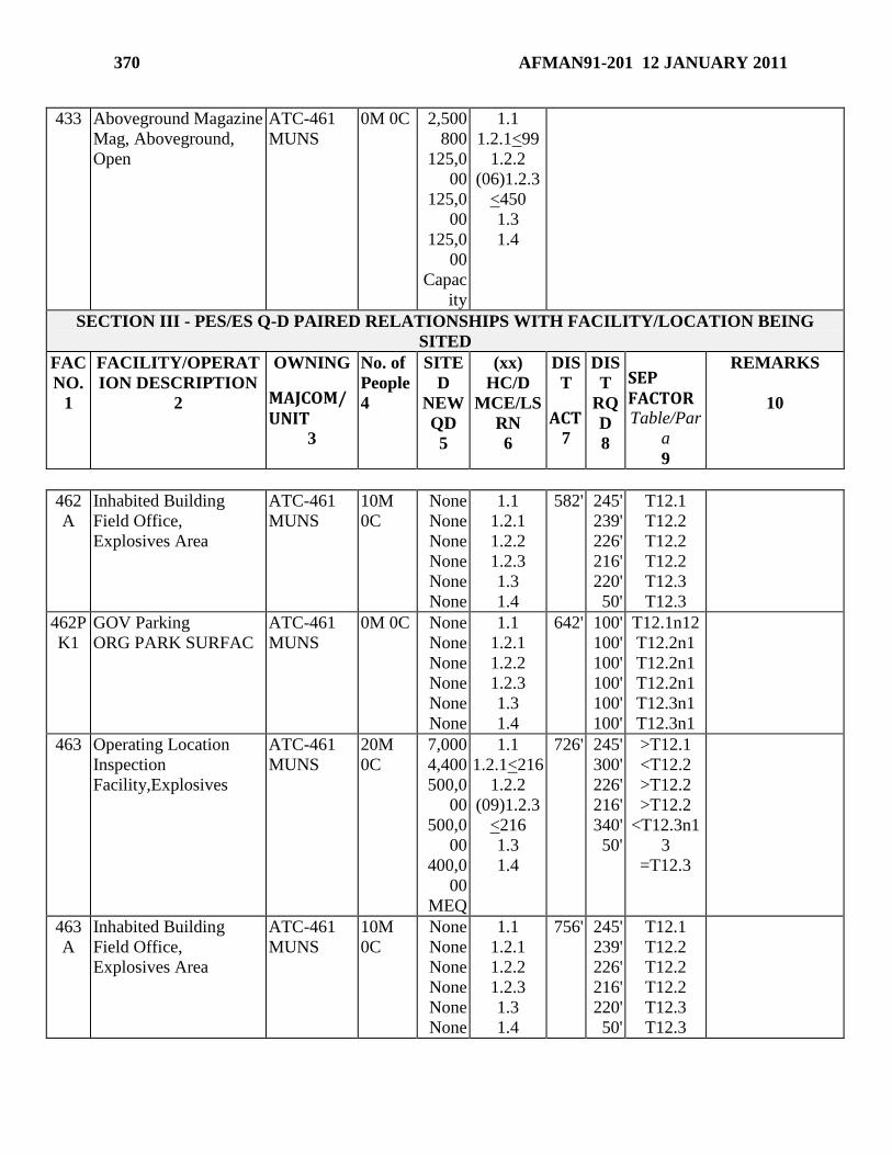
370 AFMAN91-201 12 JANUARY 2011
433 Aboveground Magazine
Mag, Aboveground,
Open
ATC-461
MUNS
0M 0C 2,500
800
125,0
00
125,0
00
125,0
00
Capac
ity
1.1
1.2.1<99
1.2.2
(06)1.2.3
<450
1.3
1.4
SECTION III - PES/ES Q-D PAIRED RELATIONSHIPS WITH FACILITY/LOCATION BEING
SITED
FAC
NO.
1
FACILITY/OPERAT
ION DESCRIPTION
2
OWNING
MAJCOM/UNIT
3
No. of
People
4
SITE
D
NEW
QD
5
(xx)
HC/D
MCE/LS
RN
6
DIS
T
ACT 7
DIS
T
RQ
D
8
SEP FACTOR Table/Par
a
9
REMARKS
10
462
A
Inhabited Building
Field Office,
Explosives Area
ATC-461
MUNS
10M
0C
None
None
None
None
None
None
1.1
1.2.1
1.2.2
1.2.3
1.3
1.4
582'
245'
239'
226'
216'
220'
50'
T12.1
T12.2
T12.2
T12.2
T12.3
T12.3
462P
K1
GOV Parking
ORG PARK SURFAC
ATC-461
MUNS
0M 0C None
None
None
None
None
None
1.1
1.2.1
1.2.2
1.2.3
1.3
1.4
642'
100'
100'
100'
100'
100'
100'
T12.1n12
T12.2n1
T12.2n1
T12.2n1
T12.3n1
T12.3n1
463 Operating Location
Inspection
Facility,Explosives
ATC-461
MUNS
20M
0C
7,000
4,400
500,0
00
500,0
00
400,0
00
MEQ
1.1
1.2.1<216
1.2.2
(09)1.2.3
<216
1.3
1.4
726'
245'
300'
226'
216'
340'
50'
>T12.1
<T12.2
>T12.2
>T12.2
<T12.3n1
3
=T12.3
463
A
Inhabited Building
Field Office,
Explosives Area
ATC-461
MUNS
10M
0C
None
None
None
None
None
None
1.1
1.2.1
1.2.2
1.2.3
1.3
1.4
756'
245'
239'
226'
216'
220'
50'
T12.1
T12.2
T12.2
T12.2
T12.3
T12.3
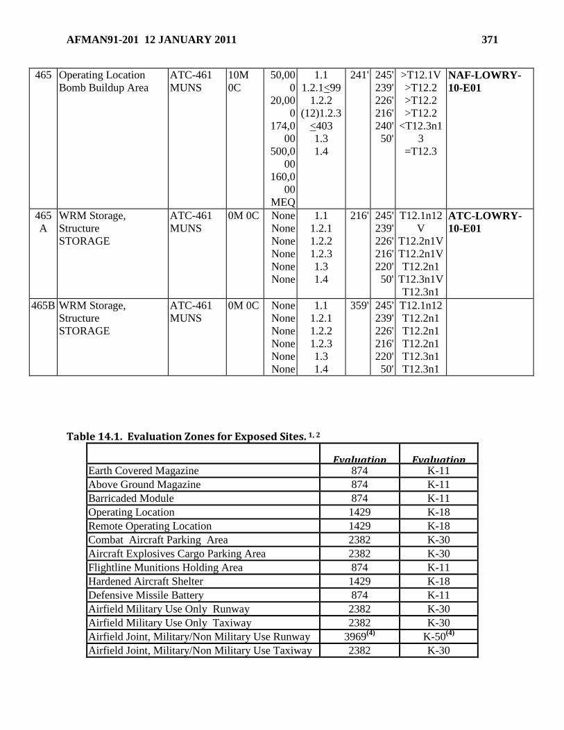
AFMAN91-201 12 JANUARY 2011 371
465 Operating Location
Bomb Buildup Area
ATC-461
MUNS
10M
0C
50,00
0
20,00
0
174,0
00
500,0
00
160,0
00
MEQ
1.1
1.2.1<99
1.2.2
(12)1.2.3
<403
1.3
1.4
241'
245'
239'
226'
216'
240'
50'
>T12.1V
>T12.2
>T12.2
>T12.2
<T12.3n1
3
=T12.3
NAF-LOWRY-
10-E01
465
A
WRM Storage,
Structure
STORAGE
ATC-461
MUNS
0M 0C None
None
None
None
None
None
1.1
1.2.1
1.2.2
1.2.3
1.3
1.4
216'
245'
239'
226'
216'
220'
50'
T12.1n12
V
T12.2n1V
T12.2n1V
T12.2n1
T12.3n1V
T12.3n1
ATC-LOWRY-
10-E01
465B WRM Storage,
Structure
STORAGE
ATC-461
MUNS
0M 0C None
None
None
None
None
None
1.1
1.2.1
1.2.2
1.2.3
1.3
1.4
359'
245'
239'
226'
216'
220'
50'
T12.1n12
T12.2n1
T12.2n1
T12.2n1
T12.3n1
T12.3n1
Table 14.1. Evaluation Zones for Exposed Sites. 1, 2
Exposed Site Evaluation
Zone (feet)
Evaluation Zone
(K-Factor)
Earth Covered Magazine 874
K-11
Above Ground Magazine 874
K-11
Barricaded Module 874
K-11
Operating Location 1429
K-18
Remote Operating Location 1429 K-18
Combat Aircraft Parking Area 2382 K-30
Aircraft Explosives Cargo Parking Area 2382
K-30
Flightline Munitions Holding Area 874
K-11
Hardened Aircraft Shelter 1429
K-18
Defensive Missile Battery 874
K-11
Airfield Military Use Only Runway 2382 K-30
Airfield Military Use Only Taxiway 2382 K-30
Airfield Joint, Military/Non Military Use Runway 3969(4)
K-50(4)
Airfield Joint, Military/Non Military Use Taxiway 2382 K-30
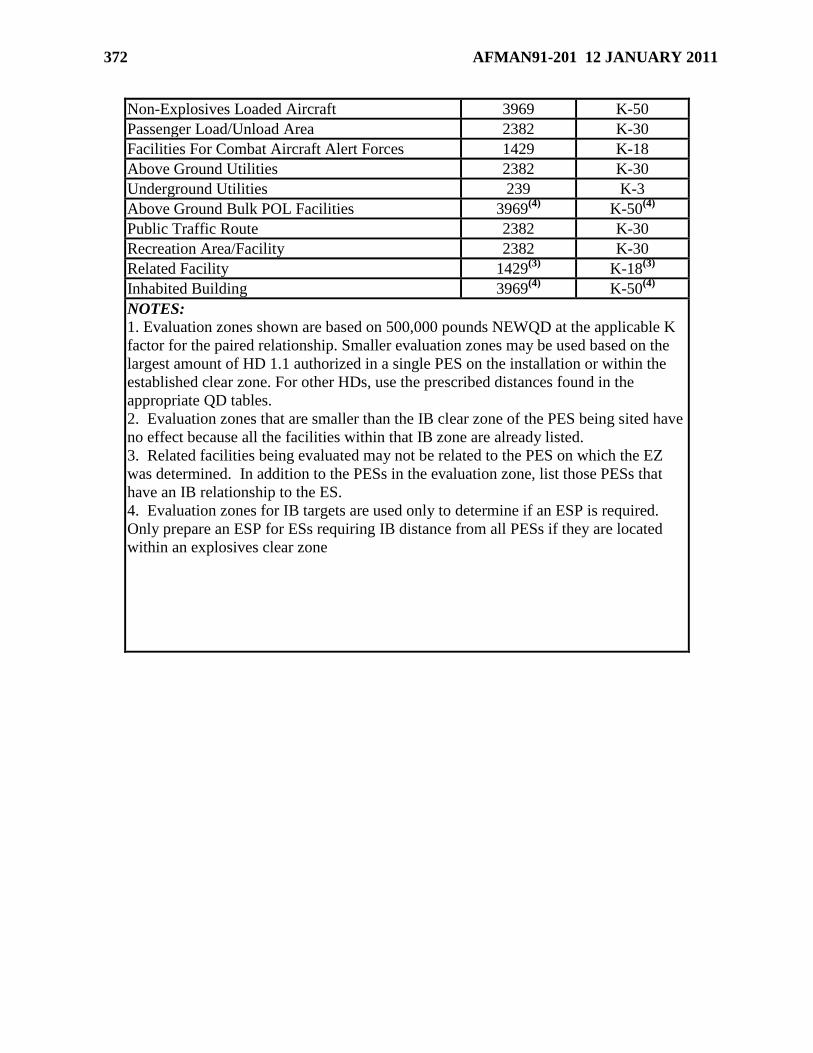
372 AFMAN91-201 12 JANUARY 2011
Non-Explosives Loaded Aircraft 3969
K-50
Passenger Load/Unload Area 2382 K-30
Facilities For Combat Aircraft Alert Forces 1429
K-18
Above Ground Utilities 2382 K-30
Underground Utilities 239 K-3
Above Ground Bulk POL Facilities 3969(4)
K-50(4)
Public Traffic Route 2382 K-30
Recreation Area/Facility 2382 K-30
Related Facility 1429(3)
K-18(3)
Inhabited Building 3969(4)
K-50(4)
NOTES:
1. Evaluation zones shown are based on 500,000 pounds NEWQD at the applicable K
factor for the paired relationship. Smaller evaluation zones may be used based on the
largest amount of HD 1.1 authorized in a single PES on the installation or within the
established clear zone. For other HDs, use the prescribed distances found in the
appropriate QD tables.
2. Evaluation zones that are smaller than the IB clear zone of the PES being sited have
no effect because all the facilities within that IB zone are already listed.
3. Related facilities being evaluated may not be related to the PES on which the EZ
was determined. In addition to the PESs in the evaluation zone, list those PESs that
have an IB relationship to the ES.
4. Evaluation zones for IB targets are used only to determine if an ESP is required.
Only prepare an ESP for ESs requiring IB distance from all PESs if they are located
within an explosives clear zone
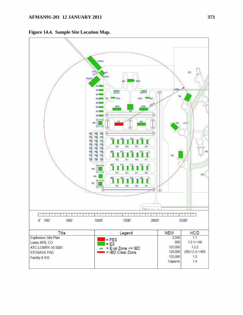
AFMAN91-201 12 JANUARY 2011 373
Figure 14.4. Sample Site Location Map.
374 AFMAN91-201 12 JANUARY 2011
Chapter 15
REAL PROPERTY KNOWN OR SUSPECTED TO CONTAIN MUNITIONS AND
EXPLOSIVES OF CONCERN AND CHEMICAL AGENTS
Section 15A—Introduction
15.1. General. Every means possible shall be used to protect the general public and the
environment from exposure to ammunition and explosive hazards. This includes all explosive
hazard areas, suspected or known to exist, on real property currently or formerly under USAF
ownership or control.
15.1.1. This chapter establishes explosives safety standards that, when applied, will protect
people and real property from explosive and CA hazards associated with:
15.1.1.1. Real property known or suspected to contain:
15.1.1.1.1. Munitions and explosives of concern (MEC).
15.1.1.1.2. CA in other than munitions configurations (e.g., DoD laboratory vials,
CA identification sets, one-ton containers, CA-contaminated soil).
15.1.1.2. Munitions responses to MEC. (A munitions response to CA-filled munitions
will be addressed as a chemical warfare material (CWM) response.)
15.1.1.3. CWM responses
15.1.2. This chapter establishes a process for determining site-specific actions that, when
taken, will:
15.1.2.1. Ensure explosives safety is addressed throughout munitions responses to MEC.
15.1.2.2. Ensure CA safety and, when applicable, explosives safety is addressed
throughout CWM responses.
15.1.2.3. Result in DDESB approval of required safety submissions for munitions
responses to MEC and for CWM responses. (See section 15.5 for required safety
submission and their contents.)
15.1.2.4. Document and report completion of:
15.1.2.4.1. Munitions responses to MEC
15.1.2.4.2. CWM responses.
15.1.3. This chapter does not apply to:
15.1.3.1. Operational ranges, with the exception of military munitions burial sites located
on such ranges.
15.1.3.2. Explosives or munitions emergency responses.
Section 15B—Explosives Safety Standards for the Identification and Control of Areas Known
or Suspected to Contain MEC or CA
AFMAN91-201 12 JANUARY 2011 375
15.2. Identification and Control. To ensure explosives and CA safety risk is identified and
controlled on real property currently or formerly under the jurisdiction, custody, or control of the
USAF, installations must:
15.2.1. Identify all areas known or suspected to present explosive or CA hazards
(Geographic Information Systems should be used):
15.2.1.1. In installation master plans for active installations. (In some cases, these areas
are also required to be identified in other documents.)
15.2.1.2. In DoD’s military Munitions Response Site Inventory for those sites that are
included in the Military Munitions Response Program (see Management Guidance for the
Defense Environmental Restoration Program (DERP) and 10 U.S.C. 2710(a).
15.2.2. Maintain permanent records of those areas identified pursuant to subparagraph
15.2.1. and ensure such records are readily available to current and futures users of the
property. Records should be retained for areas such as operational ranges, former ranges,
current or former munitions manufacturing facilities, current or former sites used for
munitions demilitarization activities, and locations previously used for the burial of
munitions. Records shall:
15.2.2.1. When practicable, include the nomenclature and the known or suspected
location.
15.2.2.2. Summarize any clearance or response (removal or remediation) actions, or
explosives or munitions emergency responses previously conducted within the area.
15.2.3. Prohibit unnecessary access and take appropriate action to deter unauthorized access
to areas under DoD control that are known or suspected of containing potential explosive or
CA hazards. Such actions may include establishing access controls (e.g. fencing the area,
establishing roving security patrols), which may be risk-based, or providing public
notifications of any potential hazards (e.g., posting unexploded ordnance (UXO)-hazard
warning signs, conducting UXO-safety education programs). When used, signs must be kept
legible and, when appropriate, in the predominant languages of the region, or as pictograms.
When the DoD does not exercise jurisdiction, custody, or control over the area (e.g.,
Formerly Used Defense Sites (FUDS)), the responsible installation shall, at a minimum,
provide written notification of the potential explosive or CA hazards to the property owner
and any known tenants. A record of this notification must be maintained as a permanent
record. (See subparagraph 15.2.2.)
15.2.3.1. Installations should, unless there is evidence to the contrary, assume the
following areas present explosive hazards:
15.2.3.1.1. Impact areas on operational ranges. Exceptions are ranges known to have
been exclusively used for training with only small arms ammunition.
15.2.3.1.2. Former ranges known or suspected to contain MEC.
15.2.3.1.3. Outdoor demolition areas, to include locations used for open burning
(OB) or open detonation (OD).
15.2.3.1.4. Areas that are associated with military munitions production,
demilitarization, renovation, or similar processes (e.g., operating buildings and any
376 AFMAN91-201 12 JANUARY 2011
installed equipment) that generated explosives residues (e.g., dust, vapors, liquids)
and that might have become contaminated with such residues in concentrations
sufficient to present explosive hazards, to include areas receiving processing
wastewater (e.g., settling ponds, drainage swales).
15.2.3.2. Installations should, unless there is evidence to the contrary, assume the
following areas present CA hazards:
15.2.3.2.1. Former CWM or CA burial sites.
15.2.3.2.2. Former CWM or CA disposal areas.
15.2.3.2.3. Former CWM impact areas.
15.2.3.2.4. Former training areas used for training with CWM or CA.
15.2.3.2.5. Former CWM or CA production and demilitarization facilities.
15.2.3.3. When access to areas known or suspected to present explosive or CA hazards is
necessary, a risk assessment to evaluate the potential hazards associated with the
proposed activity shall be completed and methods to mitigate any potential exposures
shall be implemented before access is allowed. (When access is necessary to real
property not under DoD ownership, custody, or control, installations should obtain a right
of entry for the property.)
15.2.4. Prohibit the disposal (e.g., burying, dumping) of military munitions on land or in
water except when specifically authorized by the appropriate MAJCOM in coordination with
AFSC/SEW. Such disposal actions must comply with applicable regulatory requirements.
This prohibition does not preclude:
15.2.4.1. The covering of munitions with earth to control fragments and noise during
authorized destruction by detonation.
15.2.4.2. The use of in situ capping when implemented as an engineered remedy under
an authorized response action.
Section 15C—Safety Aspects of Explosives and CA Response Actions
15.3. Response Actions
15.3.1. General
15.3.1.1. Plans for munitions responses to MEC or CWM responses shall:
15.3.1.1.1. Ensure close coordination, as applicable, between DoD explosives and
CA safety organizations, DoD environmental organizations, and appropriate
regulatory agencies and stakeholders.
15.3.1.1.2. Specify those actions necessary to protect DoD personnel, installation-
related personnel, and the public from exposure to explosive and CA hazards.
15.3.1.1.3. Provide the design for and explain the execution of:
15.3.1.1.3.1. Munitions responses, when MEC has been determined to present an
unacceptable risk.
AFMAN91-201 12 JANUARY 2011 377
15.3.1.1.3.2. CWM responses, when CA, regardless of configuration, has been
determined to present an unacceptable risk.
15.3.1.1.4. Explain how the selected response actions will achieve a degree of
protectiveness necessary for the current, determined, or reasonably anticipated future
land use.
15.3.1.1.4.1. Provide the rationale for selection of technologies to be used to
detect anomalies that can indicate the presence of MEC or CA, regardless of CA
configuration.
15.3.1.1.4.2. Address how periodically (e.g., during 5-year reviews or consistent
with long-term monitoring agreements) completed response actions will be
reviewed to ensure the response remains effective. The need for such reviews is
particularly important in areas where natural phenomena (e.g., frost heave,
soil erosion, droughts, or tidal action) could expose MEC or CA, regardless of
CA configuration, or where Land Use Controls (LUC) constitute a major
element of the response. These reviews shall consider:
15.3.1.1.4.2.1. The explosives safety aspects of munitions responses to MEC.
15.3.1.1.4.2.2. The CA safety and, when applicable, the explosives safety
aspects of CWM responses.
15.3.1.1.5. Address how the personnel qualification provisions of DDESB TP 18
will be met.
15.3.1.1.6. Be approved by the DDESB for compliance with DoD explosives safety
standards.
15.3.1.1.7. Provide for the submission of an After Action Report (AAR) to the
DDESB upon completion of the response. AAR are not provided for DDESB
approval, but are used to close out files maintained by the DDESB Staff.
15.3.1.2. Residual Explosive and CA Hazards.
15.3.1.2.1. Some areas that the military has used for munitions-related activities (e.g.,
live-fire training or testing, OB/OD) or for CA-related activities may not be
appropriate, even after the performance of response activities, for certain uses (e.g.,
residential development). Such areas include former military range impact areas on
which the military has used munitions containing either high explosives or CA and
sites used for either OB or OD. Such areas may, after a response, be better suited for
uses that restrict or limit intrusive activities (e.g., wildlife refuges, surface
recreational areas).
15.3.1.2.2. Some MEC or CA, regardless of CA configuration, might not be detected
or removed during a response. Although residual risks can be managed (e.g., by use
of agreed-upon LUC, to include safety education; recurring reviews; and construction
support), residual hazards might still exist.
15.3.1.2.3. From an explosives and, when applicable, CA safety perspective, the
degree to which MEC or CA removal is undertaken depends largely on the current,
determined, or reasonably anticipated future land use. When MEC or CA, regardless
378 AFMAN91-201 12 JANUARY 2011
of CA configuration, cannot be removed to the degree necessary to safely allow the
current, determined, or reasonably anticipated future land use, the use must be
changed or appropriately restricted to obtain DDESB approval of the relevant plan.
15.3.1.3. When DoD does not control the land and the imposition of LUC is not possible
(e.g., on FUDS), the responsible installation should, at a minimum, provide the property
owner, and any known tenants, written notification of the potential residual explosive or
CA hazards and the risks inherent in any use of property that is consistent with those
hazards.
15.3.2. Explosives Safety and CA Safety Aspects in the Selection and Design of Responses
15.3.2.1. Explosives safety must be addressed in the selection and design of a munitions
response to MEC. CA safety, and when applicable, explosives safety must be addressed
in the selection and design of a CWM response. The protection afforded by a response
must be consistent with the current, determined, or reasonably anticipated land use. The
design of the response that is included in the required submission must consider the site-
specific information below.
15.3.2.1.1. Historical Information. Historical information, which is documented in a
written report, is gathered through a records search, to include the permanent records
outlined in section 5.2., and interviews. The following information is required:
15.3.2.1.1.1. The boundaries of the response area. For munitions responses, the
Munitions Response Area (MRA) boundaries and, when appropriate, the
boundaries of any Munitions Response Sites (MRS) (e.g., firing points, impact
areas, and burial sites) within the MRA are required.
15.3.2.1.1.2. The type of MEC known or suspected to be present based on the
types of munitions-related operations, training, or testing previously performed in
the MRA or MRS.
15.3.2.1.1.3. The type and configuration of any CA known or suspected to be
present.
15.3.2.1.2. Land Use. Land use is the current, determined, or reasonably anticipated
future use of real property. Because portions of the response area (e.g., the MRA or
MRS) might be used differently (e.g., public highway, wildlife refuge, sports field,
industrial complex), different response actions (e.g., surface removal, subsurface
removal, no removal, remedial response) may be appropriate within any given
response area.
15.3.2.1.2.1. Where the land use is limited to surface activities, the munitions or
CWM response may only involve removing surface MEC or surface CA. This
removal may be technology-aided.
15.3.2.1.2.2. When the land use will involve or allow intrusive activities to occur,
the response will normally require a subsurface removal, and may require follow-
on construction support.
15.3.2.1.2.3. Where the current, determined, or reasonably anticipated land use is
compatible with the explosive or CA hazards present or suspected, a response
action to remove any explosive or CA hazards may not be necessary.
AFMAN91-201 12 JANUARY 2011 379
15.3.2.1.2.4. Where a response would adversely impact natural or cultural
resources, a removal action may not be practical.
15.3.2.1.3. Results of Onsite Investigations. These results should be used to validate
and augment information discovered during the historical review and to determine the
specific boundaries of the response area (e.g., the boundary of an MRA or of any
MRS within an MRA).
15.3.2.1.4. Analysis. Conduct a detailed analysis of available records, technical data,
and the results of onsite investigations. This analysis should evaluate:
15.3.2.1.4.1. The types of MEC or CA, regardless of CA configuration, known to
be present, to include its technical characteristics (e.g., filler, fuzing) and
estimated distribution.
15.3.2.1.4.2. The potential explosive or CA hazards present.
15.3.2.1.4.3. Physical site characteristics (e.g., flora and fauna, endangered
species, cultural items, geological, topographical, hydrological).
15.3.2.1.4.4. People potentially endangered.
15.3.2.1.4.5. Information from previous or current responses.
15.3.2.1.5. LUC. Evaluate the appropriateness and effectiveness of LUC to manage
any residual explosives safety or CA safety risks.
15.3.2.1.6. Technology. Evaluate the applicability, capabilities, and limitations of
available technologies (e.g., detection, discrimination, removal).
15.3.2.1.7. Other relevant factors.
Section 15D—Special Considerations
15.4. General
15.4.1. Explosive Soil
15.4.1.1. Because of some past munitions-related activities (e.g., settling ponds or
explosives sumps at munitions production or demilitarization facilities), concentrations of
explosives in soil (e.g., sand, sludge, clay) can exist such that the mixture itself presents
an explosive hazard. Such mixtures are referred to as ―explosive soil.‖
15.4.1.2. The NEWQD of explosive soil is the weight of the mixture multiplied by the
explosives concentration (e.g., 1,000 lbs [454 kg] of explosive soil that is 10 percent TNT
has an NEWQD of 100 lbs [45.4 kg]).
15.4.1.3. The concentration necessary to present an explosive hazard depends on the
distribution and type of explosives in the soil and the soil’s characteristics.
15.4.1.3.1. Primary (Initiating) Explosives
15.4.1.3.1.1. Soil containing 2 percent or more by weight of any primary
explosive or mixture of primary explosives presents an explosive hazard and shall
be treated as HD 1.1.
380 AFMAN91-201 12 JANUARY 2011
15.4.1.3.1.2. Soil containing less than 2 percent by weight of any primary
explosive does not present an explosive hazard.
15.4.1.3.2. Secondary Explosives.
15.4.1.3.2.1. Secondary explosives are much less sensitive than primary
explosives.
15.4.1.3.2.2. Soil containing 10 percent or more of weight of either any
secondary explosives or a mixture of secondary explosives presents an explosive
hazard and shall be treated as HD 1.1.
15.4.1.3.2.3. Soil containing less than 10 percent by weight of any secondary
explosive or a mixture of secondary explosives does not present an explosive
hazard.
15.4.1.3.3. Nitroglycerin, Nitrocellulose, and Nitroguanidine
15.4.1.3.3.1. Soil containing 10 percent or more by weight of nitroglycerine,
nitrocellulose, or nitroguanidine presents an explosive hazard and shall be treated
as HD 1.1.
15.4.1.3.3.2. Soil containing less than 10 percent by weight of nitroglycerin,
nitrocellulose, or nitroguanidine does not present an explosive hazard. (Care must
be taken when applying this threshold rule to less-permeable soils, such as clay,
that may cause nitroglycerin to pool, rather than be absorbed.)
15.4.1.3.4. Other Energetic Materials Mixtures. The potential explosive hazard of
such mixtures in soil may be unknown and may require testing. If the hazard is
unknown, manage soil mixtures containing only propellants as secondary explosives,
and all other soil mixtures containing energetics (e.g., liquid propellants) as primary
explosives.
15.4.2. Real Property (Buildings and Installed Equipment). Military munitions operating
buildings (e.g., munitions production or demilitarization facilities) and any installed
equipment may contain residual explosives that present an explosive hazard. Of particular
concern are building features (e.g., floors, roofs, walls, drains, internal and external piping,
ventilation systems) in which explosives residues could present explosive hazards and
industrial equipment, particularly equipment with internal cavities from facilities used in
munitions production or demilitarization operations (e.g., cast loading or milling, steam-out)
that generated explosives residues (e.g., dust, vapors, liquids). To the extent such buildings or
installed equipment is believed to present an explosive or CA hazard, installations, in
coordination with MAJCOM and AFSC/SEW, must submit to the DDESB for use of such
buildings and installed equipment before use or transfer for purpose incompatible with the
presence of the explosive hazard (see DoD 6055.09-M, Volume 7, for additional
information).
15.4.3. Construction Support
15.4.3.1. Responsible installations should consider the level of construction support
required, based on site-specific data, during the below activities.
AFMAN91-201 12 JANUARY 2011 381
15.4.3.1.1. Intrusive activities (e.g., building construction, laying utilities, or road
improvements) on property known or suspected to contain MEC or CA, regardless of
CA configuration, or on property where residual explosive or CA hazards may exist.
15.4.3.1.2. The removal or remediation of debris or media in areas where there is a
probability of encountering MEC (e.g., former OB/OD grounds) or CA.
15.4.3.2. The responsible authority (e.g., installation commander or designated
representative) will determine whether such support is required and the level of effort of
required support on a case-by-case basis (see subparagraph 15.5.7). Construction support
is determined by the probability of encountering MEC or CA, regardless of CA
configuration.
15.4.3.2.1. Low Probability. ―On-call‖ construction support is appropriate
15.4.3.2.1.1. A ―low‖ determination may only be assigned to those areas for
which a search of available historical records and onsite investigation data
indicates that, given the military or munitions-related activities that occurred at
the site, the likelihood of encountering MEC or CA, regardless of CA
configuration, is low.
15.4.3.2.1.2. Munitions-related activities that may merit a ―low‖ determination
include, but are not limited to, the former use of the area for live-fire training
exclusively with small arms ammunition; for maneuver training, to include
maneuver training involving the use of smokes, pyrotechnics, and simulators; as
firing points; for munitions inspection, handling, storage, or transfers, to include
residue points and inert storage yards; for air defense; or as munitions operating
facilities. The exceptions are facilities in which the processes used might have
resulted in the generation of concentrations of munitions constituents high enough
to present an explosive hazard. Areas on which previous responses have been
completed may also qualify for ―low‖ determinations.
15.4.3.2.1.3. Immediate reassessment by the responsibility authority of the level
of construction support required is appropriate upon the discovery of MEC or CA,
regardless of CA configuration.
15.4.3.2.2. Moderate to High Probability. ―Onsite‖ construction support should be
provided to remove explosive or CA hazards in the construction footprint, per a
DDESB-approved ESS or CSS, before intrusive construction or other intrusive
activities occur. (NOTE: When the depth of intrusive activities exceeds the detection
limits of the detection equipment used, soil should be removed in layers to allow
detection and removal of MEC or CA, regardless of CA configuration, in the
construction footprint.)
15.4.3.2.2.1. A ―moderate to high‖ determination may be assigned to those areas
for which a search of available historical records or onsite investigation data
indicates that, given the military or munitions-related activities that occurred at
the site, there is more than a low probability that MEC or CA are present.
15.4.3.2.2.2. Munitions-related activities that may merit a ―moderate to high‖
determination include, but are not limited to, the former use of the area for live-
382 AFMAN91-201 12 JANUARY 2011
fire training other than exclusively with small arms ammunition; as operational
range impact areas; for OB or OD of munitions; as munitions operating facilities
where processes used might have resulted in the generation of concentrations of
munitions constituents high enough to present an explosive hazard; for munitions
burial; or for any activities involving CA.
15.4.4. Anomaly Avoidance
15.4.4.1. The use of anomaly avoidance techniques is appropriate on properties known
or suspected to contain UXO or other munitions (e.g., Discarded Military Munitions
(DMM)) that may have experienced abnormal environments to allow the below activities
in such areas while avoiding surface explosive or CA hazards and, when necessary,
subsurface anomalies. Anomaly avoidance is used when:
15.4.4.1.1. Surface MEC or CA, regardless of CA configuration, will be avoided
during any activities that require entry to the area (e.g., collections of environmental
samples, the conduct of cultural resource studies).
15.4.4.1.2. Subsurface anomalies will be avoided during any intrusive work (e.g.,
drilling environmental monitory wells).
15.4.4.2. During anomaly avoidance:
15.4.4.2.1. Escort support must be provided by EOD personnel, or:
15.4.4.2.1.1. Within areas known or suspected to contain MEC, excluding CA,
regardless of configuration, by UXO-qualified personnel as outlined in DDESB
TP 18.
15.4.4.2.1.2. Within areas known or suspected to contain CA, regardless of
configuration, to include areas where such CA is commingled with other MEC, by
UXO-qualified personnel trained in CWM responses.
15.4.4.2.2. Explosives safety requires that discovered surface MEC or CA, regardless
of CA configuration, be avoided and their location noted and reported to appropriate
authorities.
15.4.4.2.3. Detected subsurface anomalies must not be investigated, but they shall be
marked, when appropriate, and avoided.
15.4.5. Frost Heave. This phenomenon occurs when three conditions are met: (a) freezing
temperatures are present in the soil column; (b) the soil is frost susceptible; and (c) there is
sufficient moisture present in the soil to cause soil movement upon ice crystal formation.
These three factors will be evaluated to assess the likelihood of frost heave moving residual
MEC or CA, regardless of CA configuration, upward through the soil column. Where frost
heave may have such an effect, explosives safety requires procedures be implemented to
monitor the effectiveness of response actions for the affected area. (Other naturally occurring
phenomena (e.g., erosion, tidal changes) could necessitate similar monitoring.)
15.4.6. Soil Containing CA
15.4.6.1. The criteria below apply to soil known to be contaminated with one or more of
the following CA: mustard, L, GD, GA/GB, O-cyclohexyl Methylphosphono-flouridate
(GF) (common name is cylcosarin), or VX. This criteria applies only if a headspace
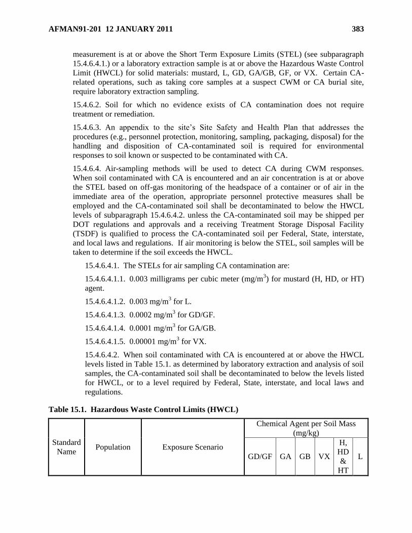
AFMAN91-201 12 JANUARY 2011 383
measurement is at or above the Short Term Exposure Limits (STEL) (see subparagraph
15.4.6.4.1.) or a laboratory extraction sample is at or above the Hazardous Waste Control
Limit (HWCL) for solid materials: mustard, L, GD, GA/GB, GF, or VX. Certain CA-
related operations, such as taking core samples at a suspect CWM or CA burial site,
require laboratory extraction sampling.
15.4.6.2. Soil for which no evidence exists of CA contamination does not require
treatment or remediation.
15.4.6.3. An appendix to the site’s Site Safety and Health Plan that addresses the
procedures (e.g., personnel protection, monitoring, sampling, packaging, disposal) for the
handling and disposition of CA-contaminated soil is required for environmental
responses to soil known or suspected to be contaminated with CA.
15.4.6.4. Air-sampling methods will be used to detect CA during CWM responses.
When soil contaminated with CA is encountered and an air concentration is at or above
the STEL based on off-gas monitoring of the headspace of a container or of air in the
immediate area of the operation, appropriate personnel protective measures shall be
employed and the CA-contaminated soil shall be decontaminated to below the HWCL
levels of subparagraph 15.4.6.4.2. unless the CA-contaminated soil may be shipped per
DOT regulations and approvals and a receiving Treatment Storage Disposal Facility
(TSDF) is qualified to process the CA-contaminated soil per Federal, State, interstate,
and local laws and regulations. If air monitoring is below the STEL, soil samples will be
taken to determine if the soil exceeds the HWCL.
15.4.6.4.1. The STELs for air sampling CA contamination are:
15.4.6.4.1.1. 0.003 milligrams per cubic meter (mg/m3) for mustard (H, HD, or HT)
agent.
15.4.6.4.1.2. 0.003 mg/m3 for L.
15.4.6.4.1.3. 0.0002 mg/m3 for GD/GF.
15.4.6.4.1.4. 0.0001 mg/m3 for GA/GB.
15.4.6.4.1.5. 0.00001 mg/m3 for VX.
15.4.6.4.2. When soil contaminated with CA is encountered at or above the HWCL
levels listed in Table 15.1. as determined by laboratory extraction and analysis of soil
samples, the CA-contaminated soil shall be decontaminated to below the levels listed
for HWCL, or to a level required by Federal, State, interstate, and local laws and
regulations.
Table 15.1. Hazardous Waste Control Limits (HWCL)
Standard
Name Population Exposure Scenario
Chemical Agent per Soil Mass
(mg/kg)
GD/GF GA GB VX
H,
HD
&
HT
L
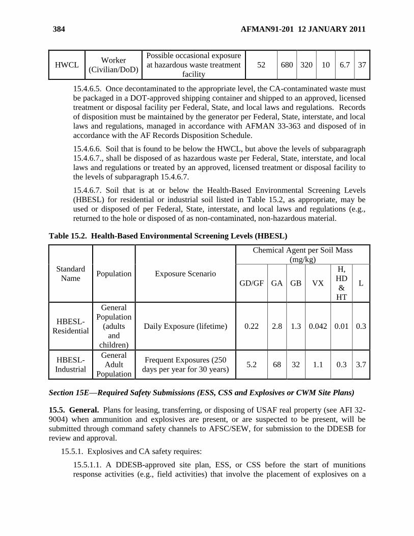
384 AFMAN91-201 12 JANUARY 2011
HWCL Worker
(Civilian/DoD)
Possible occasional exposure
at hazardous waste treatment
facility
52 680 320 10 6.7 37
15.4.6.5. Once decontaminated to the appropriate level, the CA-contaminated waste must
be packaged in a DOT-approved shipping container and shipped to an approved, licensed
treatment or disposal facility per Federal, State, and local laws and regulations. Records
of disposition must be maintained by the generator per Federal, State, interstate, and local
laws and regulations, managed in accordance with AFMAN 33-363 and disposed of in
accordance with the AF Records Disposition Schedule.
15.4.6.6. Soil that is found to be below the HWCL, but above the levels of subparagraph
15.4.6.7., shall be disposed of as hazardous waste per Federal, State, interstate, and local
laws and regulations or treated by an approved, licensed treatment or disposal facility to
the levels of subparagraph 15.4.6.7.
15.4.6.7. Soil that is at or below the Health-Based Environmental Screening Levels
(HBESL) for residential or industrial soil listed in Table 15.2, as appropriate, may be
used or disposed of per Federal, State, interstate, and local laws and regulations (e.g.,
returned to the hole or disposed of as non-contaminated, non-hazardous material.
Table 15.2. Health-Based Environmental Screening Levels (HBESL)
Standard
Name Population Exposure Scenario
Chemical Agent per Soil Mass
(mg/kg)
GD/GF GA GB VX
H,
HD
&
HT
L
HBESL-
Residential
General
Population
(adults
and
children)
Daily Exposure (lifetime) 0.22 2.8 1.3 0.042 0.01 0.3
HBESL-
Industrial
General
Adult
Population
Frequent Exposures (250
days per year for 30 years) 5.2 68 32 1.1 0.3 3.7
Section 15E—Required Safety Submissions (ESS, CSS and Explosives or CWM Site Plans)
15.5. General. Plans for leasing, transferring, or disposing of USAF real property (see AFI 32-
9004) when ammunition and explosives are present, or are suspected to be present, will be
submitted through command safety channels to AFSC/SEW, for submission to the DDESB for
review and approval.
15.5.1. Explosives and CA safety requires:
15.5.1.1. A DDESB-approved site plan, ESS, or CSS before the start of munitions
response activities (e.g., field activities) that involve the placement of explosives on a
AFMAN91-201 12 JANUARY 2011 385
site; the intentional physical contact with MEC or CA, regardless of CA configuration; or
the conduct of ground-disturbing or other intrusive activities in areas known or suspected
to contain MEC or CA, regardless of CA configuration; or
15.5.1.2. An AFSC/SEW review and approval pending DDESB review and approval of
the submission, provided the submission is at the DDESB for review and approval and
the submitting MAJCOM understands that DDESB approval may impose different or
additional munitions or CWM response requirements.
15.5.2. A DDESB-approved ESS or CSS, or an explosives or CWM site plan, or a
combination thereof, is required for:
15.5.2.1. MRS investigation or characterization (e.g., Engineering Evaluation/Cost
Analysis (EE/CA) or Remedial Investigation/Feasibility Study (RI/FS)) that involve the
intentional physical contact with MEC or CA, regardless of CA configuration (see
subparagraph 15.5.4.).
15.5.2.2. A determination of ―No DoD Action Indicated‖ (NDAI) or ―No Further
Action‖ (NOFA) (see subparagraph 15.5.5).
15.5.2.3. Time Critical Removal Action (TCRA) (see subparagraph 15.5.6.).
15.5.2.4. Construction support (see subparagraph 15.5.7.).
15.5.2.5. Execution of the explosives safety or CA safety aspects of the selected response
(see subparagraphs 15.5.8. and 15.5.9).
15.5.3. A DDESB-approved ESS or CSS, or an explosives or CWM site plan is not required
for:
15.5.3.1. Munitions or explosives emergency responses.
15.5.3.2. Preliminary assessments or site inspections (e.g., site visits in conjunction with
an archival search) when intentional physical contact with MEC or CA, regardless of CA
configuration, or the conduct of ground-disturbing or other intrusive activities are not
intended (see subparagraph 15.5.3.6.)
15.5.3.3. Clearance activities on operational ranges. (Addressing military munitions
burial sites on operational ranges is not a clearance activity.)
15.5.3.4. Munitions responses on former ranges used exclusively for training with small
arms ammunition.
15.5.3.5. On-call construction support
15.5.3.6. Anomaly avoidance activities
15.5.4. MRS Investigation or Characterization. An explosives or, when appropriate, a CWM
site plan is required for MRS investigations or characterizations that involve intentional
physical contact with MEC or CA, regardless of CA configuration. Such site plans will
address areas (e.g., magazines) used for the storage of commercial or military demolition
explosives, MEC or CA, regardless of CA configuration; planned or established demolition
or disposal areas; and the MRA, MRS, or response area boundaries. (See subparagraph
15.5.8.3.7.) MRS investigation and characterization are used to collect the information
386 AFMAN91-201 12 JANUARY 2011
needed to design the required munitions response and to prepare, as appropriate, an ESS or
CSS for the selected response.
15.5.5. NDAI or NOFA ESS or CSS. When a NDAI or NOFA decision is made for an MRA
or MRS or for a response area, an ESS or CSS must, at a minimum, provide:
15.5.5.1. The site identification (e.g., name, unique identifier).
15.5.5.2. The site location.
15.5.5.3. Justification for the decision.
15.5.6. TCRA ESS or CSS. To expedite the approval process, installations are encouraged to
submit TCRA ESS or CSS electronically through their chain of command to the DDESB. A
TCRA ESS or CSS must, at a minimum, identify or provide:
15.5.6.1. The site identification (e.g., name, unique identifier).
15.5.6.2. The TCRA’s location.
15.5.6.3. The TCRA’s purpose, in sufficient detail to explain the reason the TCRA was
authorized.
15.5.6.4. The estimated date that the TCRA will be:
15.5.6.4.1. Initiated.
15.5.6.4.2. Completed.
15.5.6.5. The munitions item with the greatest fragmentation distance (MGFD)
15.5.6.6. ESQD maps (see subparagraph 15.5.8.3.7.) that show the minimum separation
distances for:
15.5.6.6.1. The removal area within an MRA or MRS or within a response area for:
15.5.6.6.1.1. Unintentional detonations (see subparagraph 15.5.8.3.2.1.).
15.5.6.6.1.2. Intentional detonations (see subparagraph 15.5.8.3.2.2.).
15.5.6.6.2. Areas or magazines for the storage of demolition explosives, MEC, or
CA, regardless of CA configuration.
15.5.6.7. Actions and controls to be implemented (e.g., surface removal, evacuation,
fences) as part of the TCRA.
15.5.6.8. DDESB-approved engineering controls to be used, if any.
15.5.6.9. A point of contact for additional information
15.5.7. Construction support ESS or CSS. A safety submission is required for construction
support where the probability of encountering MEC or CA, regardless of CA configuration,
is considered moderately or highly probable. This submission must provide the information
outlined in paragraphs 15.5.8. and 15.5.9., as appropriate. The information may be tailored
based on site-specific conditions.
15.5.8. Selected Munitions Response ESS. The information below is required in an ESS for
the execution of the selected munitions response to address MEC. When CA, regardless of
configuration, is known or suspected to be present a long with explosive hazards, or when it
AFMAN91-201 12 JANUARY 2011 387
is explosively configured, a submission that provides both explosives safety (as outlines in
this section) and CA safety information (see paragraph 15.5.9.) is required.
15.5.8.1. Background. The ESS must provide, for informational purposes, a brief
description of the reasons for the munitions response. The ESS must identify or provide:
15.5.8.1.1. The scope of munitions response activities.
15.5.8.1.2. Any significant differences in munitions response activities that will
occur within the MRA or MRS. (NOTE: The ESS must identify significant
differences in the current, determined, or reasonably anticipated future land use of
different sections of the property, significant differences in the types or conditions of
MEC expected to be encountered, and any sections of the MRA that will not require
munitions response activities.)
15.5.8.2. Maps. The following maps and related information must be furnished:
15.5.8.2.1. Regional Map. A map depicting the regional location of the MRA or
MRS (e.g., a state or boundary illustration map with the MRA indicated on it).
15.5.8.2.2. MRA or MRS Maps. Include maps of the area or areas at which the
munitions response is planned. These maps and related information shall indicate:
15.5.8.2.2.1. Areas that:
15.5.8.2.2.1.1. Contain or are suspected of containing MEC that the ESS
addresses
15.5.8.2.2.1.2. Were suspected of containing MEC, but that research or site
characterizations have subsequently shown do not contain such.
15.5.8.2.2.1.3. The ESS does not address, but that either a previous safety
submission addressed or a future safety submission will address.
15.5.8.2.2.2. The current, determined, or reasonably anticipated future land use of
property within the MRA or MRS that is known or suspected to contain MEC that
the ESS addresses.
15.5.8.2.2.3. The ownership and land use of adjacent properties, as appropriate.
15.5.8.2.2.4. Any other situation that may influence or require consideration
during the response (e.g., flight corridors, traffic routes).
15.5.8.3. ESQD
15.5.8.3.1. The planned locations for MEC response-related operations must be
shown on Explosives Safety Quantity Distance (ESQD) maps. (NOTE: Preliminary
site work, such as surveying, laying search lanes, and detecting anomalies does not
require establishment of an ESQD arc.)
15.5.8.3.2. ESQD arcs for both intentional and unintentional detonations must be
established and shown on ESQD maps for each MRS.
15.5.8.3.2.1. The Minimum Separation Distance (MSD) for unintentional
detonations, which may be reduced by employing DDESB-approved engineering
controls, for:
388 AFMAN91-201 12 JANUARY 2011
15.5.8.3.2.1.1. Nonessential personnel is the greatest distance of:
15.5.8.3.2.1.1.1. Blast overpressure, as computed by using the formula: D =
40W1/3
.
15.5.8.3.2.1.1.2. The calculated HFD.
15.5.8.3.2.1.2. Team Separation distance (TSD) is based on blast
overpressure, as computed by the formula: D = 40W1/3
.
15.5.8.3.2.2. The MSD for intentional detonations (see Chapter 12), which may
be reduced by employing DDESB-approved engineering controls, is the greatest
distance of:
15.5.8.3.2.2.1. Blast overpressure, as computed by using the formula: D =
328W1/3
.
15.5.8.3.2.2.2. The calculated Maximum Fragment Distance (MFD) (see
chapter 12).
15.5.8.3.3. MEC, Excluding CA-filled Munitions, Hazard Classification, and Storage
15.5.8.3.3.1. Recovered MEC, other than Recovered CWM (RCWM), shall be
managed as HD 1.1, unless assigned differently by an Interim Hazard
Classification (IHC) authority, and assigned an appropriate CG. When storage at
the MRA or MRS is necessary, recovered MEC must be stored separately from
serviceable munitions and from any RCWM. (NOTE: For RCWM, see
subparagraph 15.5.9.6.)
15.5.8.3.3.2. Nonessential personnel in structures shall be afforded protection
equivalent to IBD from storage locations. Nonessential personnel in the open shall
be afforded protection equivalent to Public Traffic Route Distance (PTRD) from
storage locations. (See Chapter 12.) There is no required ESQD protection for
essential personnel from locations they are using for storage.
15.5.8.3.3.3. The Intermagazine Distance (IMD), based on the Net Explosive
Weight Quantity Distance (NEWQD) of the munition with the greatest NEWQD
that is reasonably expected to be encountered, applies from intrusive operations to
storage sites to prevent propagation to a storage location in event of an accidental
explosion during intrusive operations. For distances less than IMD, DDESB-
approved engineering controls must be used during intrusive operations.
15.5.8.3.4. Planned or Established Demolition Areas. A planned or established
demolition area is an area used repetitively to destroy munitions during a munitions
response. (Such areas may be an existing OD area or a new area planned for
intentional detonation.) An ESQD arc must be provided around demolition areas.
The size of the ESQD arc will be based on requirements of this Manual (see Chapter
12).
15.5.8.3.5. Mechanized MEC Processing Operations, Excluding CA-filled Munitions
15.5.8.3.5.1. These processing operations can be classified as either ―high input‖
or ―low input‖ based on a risk assessment that considers the degree of energy with
which the process would impact any MEC potentially processed.
AFMAN91-201 12 JANUARY 2011 389
15.5.8.3.5.1.1. High-input processing operations (e.g., shredders, crushers)
are intended to physically deform material including any MEC being
processed, and certain excavations depending upon the risk assessment.
15.5.8.3.5.1.2. Low-input processing operations (e.g., on-site transport,
dumping, screening, raking, spreading, sifting, and magnetically separating)
are not intended to intentionally deform material including MEC being
processed, and certain excavations depending upon the risk assessment.
15.5.8.3.5.2. Personnel Separation Distances
15.5.8.3.5.2.1. Nonessential Personnel.
15.5.8.3.5.2.1.1. During high-input processing operations, nonessential
personnel shall be provided protection for intentional detonations (see
subparagraph 15.5.8.3.2.2.) based on the MGFD.
15.5.8.3.5.2.1.2. During low-input processing operations, nonessential
personnel shall be provided protection for accidental (unintentional)
detonations (greater of HFD or K40).
15.5.8.3.5.3. Essential Personnel. For both high- and low-input processing
operations, essential personnel shall:
15.5.8.3.5.3.1. Be protected by shields or barricades designed to defeat
hazardous fragments from the MGFD.
15.5.8.3.5.3.2. Be separated from the operation by K24 based on the munition
with the greatest NEWQD that is reasonably expected to be encountered.
(NOTE: DDESB-approved overpressure-mitigating engineering controls may
be used to provide an equivalent level of protection (2.3 psi) [15.9 kPa]).
15.5.8.3.6. Intentional Burning of Buildings Contaminated with Explosives Residues
that Present an Explosive Hazard. All personnel shall be separated by K328
overpressure distance based on the Maximum Credible Event (MCE) for the building,
but not less than 1,250 feet.
15.5.8.3.7. ESQD Maps. (NOTE: The ESQD arcs and the MRA and MRS
boundaries may be shown on the same map provided all PES and ES are shown in
sufficient detail.)
15.5.8.3.7.1. ESQD-maps should be to scale and legible per subparagraph
14.24.2.
15.5.8.3.7.2. When a map does not contain a scale, all distances must be labeled.
15.5.8.3.7.3. The ESQD map shall show the following:
15.5.8.3.7.3.1. Each MRA or MRS.
15.5.8.3.7.3.2. The storage locations for demolition explosives and for
recovered MEC.
15.5.8.3.7.3.3. Locations (planned or established) for the intentional
detonations or burning of MEC, excluding CA-filled munitions. Such
390 AFMAN91-201 12 JANUARY 2011
locations include areas where contained detonation technology will be used.
15.5.8.3.7.3.4. All ES and PES and their relationships. (NOTE: Describe any
protective measures (e.g., evacuation of inhabited buildings, blocking off
public highways) that will be used to eliminate or minimize any exposures
within the established exclusion zone.)
15.5.8.3.7.3.5. All controlling ESQD arcs.
15.5.8.3.7.4. ESQD Arcs. ESQD arcs must be shown for:
15.5.8.3.7.4.1. Munitions. The MGFD shall be used for ESQD purposes for
any particular MRA or MRS. However, if a munition with a greater
fragmentation distance is encountered during the conduct of a munitions
response, the ESQD arcs must be adjusted and the ESS or explosives safety
site plan must be amended.
15.5.8.3.7.4.2. Explosive Soil. To determine the ESQD arc for explosive
soil, calculate the MCE by multiplying the weight of the mix by the
concentration of explosives (e.g., 1,000 lb of soil containing 15 percent TNT
has an MCE of 150 lb). When concentrations vary within the site, weighted
averages or other valid mathematical technique can be used to determine the
exclusion zone; however, the ESS must support their use. The MSD for
nonessential personnel shall be the greater of IBD for overpressure or the soil
ejecta radius per DDESB-approved procedures.
15.5.8.3.7.4.3. Real Property (Buildings and Installed Equipment). For
real property that is known or suspected to be contaminated with explosives
residues that present an explosive hazard, and that is slated for cleanup or
dismantlement, the MCE will be estimated on a case-by-case basis. The ESS
shall include the rationale used for the estimation.
15.5.8.3.8. Soil Sampling Maps. When the property involves concentrations of
explosives in the soil that are high enough to present an explosive hazard (see
subparagraph 15.4.1.):
15.5.8.3.8.1. Provide a map that indicates areas that were determined to contain
explosive soil.
15.5.8.3.8.2. Address methods (e.g., blending, bio-remediation) to be used to
reduce explosives concentrations to a non-reactive level.
15.5.8.3.8.3. Address methods (e.g., wetting the soil before blending) to be used
to reduce any explosive hazards.
15.5.8.4. Types of MEC. Based on research or data generated from characterization of
the MRA or MRs, provide the types of MEC expected to be encountered during
munitions response activities.
15.5.8.5. Start Date. Provide the expected date that munitions response activities that
involve the placement of explosives on a site, the intentional physical contact with MEC,
or the conduct of ground-disturbing or intrusive activities in areas known or suspected to
contain MEC are scheduled to start. Indicate the potential consequence, if any, if
AFMAN91-201 12 JANUARY 2011 391
DDESB approval does not occur by the start date. (Site preparation activities (e.g.,
surveying, gridding, or locating anomalies) may be conducted while awaiting DDESB
approval of ESS.)
15.5.8.6. MEC Migration. Describe naturally occurring phenomena (e.g., drought,
flooding, erosion, frost heave, tidal changes) that could cause the migration or exposure
of MEC, and procedures for monitoring and managing such.
15.5.8.7. Detection Equipment and Response Techniques. The intent of this section is
to describe the capabilities of detection equipment relative to the degree of removal
required to support the current, determined, or reasonably anticipated end use.
15.5.8.7.1. Describe the techniques to be used to detect and remove MEC.
15.5.8.7.2. Identify the types of detection equipment to be used and the areas in
which they will be employed.
15.5.8.7.3. Summarize methods used (e.g., test plots) to establish the expected
detection capabilities of the equipment used. If anomaly discrimination will be used,
explain what methods will be sued to establish the expected accuracy of the
discrimination.
15.5.8.7.4. When describing the detection methods:
15.5.8.7.4.1. Describe the rationale (e.g., best available technology based on
geology, topography, munitions characteristics, resource requirements) used to
select the detection methods and technologies to be used during the response.
15.5.8.7.4.2. Address any limitations (e.g., equipment, terrain, soil type) and
mitigating actions, if any.
15.5.8.7.4.3. Describe quality assurance and quality control (QA/QC) standards
and pass or fail criteria for QA/QC control audits.
15.5.8.8. Disposition Techniques
15.5.8.8.1. MEC, Excluding CA-Filled Munitions
15.5.8.8.1.1. Briefly, describe the MEC, excluding CA-filled munitions,
disposition techniques (e.g., OB, OD, contained detonation, incineration) to be
used.
15.5.8.8.1.2. When recovered MEC, excluding CA-filled munitions, cannot be
destroyed within the MRA or MRS, address how explosives safety requirements
will be met during transportation and during offsite storage, treatment, or
disposal. (NOTE: disposition actions should consider requirements applicable to
waste military munitions.)
15.5.8.8.2. Material Potentially Presenting an Explosive Hazard (MPPEH). Describe
the process to be used to manage MPPEH (see DoD 6055.09-M, Volume 7, Enclosure
6).
15.5.8.9. Environmental, Ecological, Cultural and Other Considerations. Address any
environmental, ecological (e.g., endangered species), cultural (e.g., archaeological, tribal
392 AFMAN91-201 12 JANUARY 2011
spiritual or gathering sites) and other factors that impacted, from an explosives safety
perspective, the selection of the munitions response.
15.5.8.10. Technical Support. Summarize EOD, U.S. Army Forces Command/20th
Support Command/22nd
Chemical Battalion, or UXO-technician or UXO-qualified
personnel support that may be required. (NOTE: U.S. Army Forces Command/20th
Support Command/22nd
Chemical Battalion is manned with specially trained personnel
that provide verification, sampling, detection, mitigation, render safe, decontamination,
packaging, escort, and remediation of chemical, biological and industrial devices or
hazardous materials.)
15.5.8.11. Residual Risk Management. Address:
15.5.8.11.1. LUC. The ESS must summarize any LUC to be implemented and
maintained on the property.
15.5.8.11.2. Long-Term Management. The ESS must address how any potential
residual risks will be managed.
15.5.8.12. Safety Education Program. Address methods to be used to educate the
public on the risks associated with MEC and CA, regardless of CA configuration.
15.5.8.13. Stakeholder Involvement. Briefly, summarize how stakeholder concerns
affecting the explosives safety aspects of the selected munitions response were addressed.
15.5.8.14. Contingencies. To reduce the need to submit amendments (see subparagraph
15.6.1.), an ESS may describe alternative actions that could be used to address
contingencies. As an example, an ESS may list alternative DDESB-approved
engineering controls that may be used under specified conditions.
15.5.8.15. Unexpected CA Discoveries. Should CA, regardless of its configuration, be
discovered during munitions responses to MEC, excluding CA-filled munitions, all onsite
activities shall be halted until the need for a CWM response is evaluated and a decision is
approved by the Service-level explosives safety office. If it is decided that a CWM
response is necessary, response actions that involve the intentional physical contact with
CA, regardless of configuration, or the conduct of ground-disturbing or other intrusive
activities in areas known or suspected to contain CA shall not begin until the required
CSS or CWM site plan is approved by the DDESB.
15.5.9. Selected CWM Response CSS and CWM Site Plans
15.5.9.1. General
15.5.9.1.1. A response in an area (e.g., a munitions response in an MRA or MRS)
that is known or suspected to contain CA, regardless of configuration, must include a
CWM site plan for an Interim Holding Facility (IHF) and, when the use of onsite
destruction technology is planned, for the site at which those destruction activities
will occur. Generally, the information required in CSS parallels that for an ESS (see
subparagraph 15.5.8); however, such information will be tailored to address CWM.
15.5.9.1.2. A CSS is not required for certain activities on a site with a history of CA-
related activities when an installation or district commander, or a command-
designated representative, has approved a probability assessment finding for such
AFMAN91-201 12 JANUARY 2011 393
activities stating that the probability of discovering CA is expected to be ―seldom‖ or
―unlikely.‖ However, the site safety and health plan must include contingency plans
providing for the safe and expeditious evacuation of the site in the event CA is
discovered. Should CA, regardless of configuration, be discovered during these
activities, all onsite activities shall be halted until the need for a CWM response is
evaluated and a decision is approved by the Service-level explosives safety office. If
it is decided that a CWM response is necessary, response actions that involve the
intentional physical contact with CA, regardless of configuration, and/or the conduct
of ground-disturbing or other intrusive activities in areas known or suspected to
contain CA shall not begin until the required CSS or CWM site plan is approved by
the DDESB.
15.5.9.2. Explosives Hazards. When explosives hazards are known or suspected to
exist along with CA hazards within a response area (e.g., the MRA or MRS), a
submission that addresses both explosives safety (see subparagraph 15.5.8) and CA
safety (as outlined in this section) is required.
15.5.9.3. Background. (see subparagraph 15.5.8.1)
15.5.9.4. Maps. The maps provided with a CSS must meet the requirements of
subparagraph 15.5.8.2. In addition, the One Percent Lethality Distance and the IBD shall
be shown.
15.5.9.5. Chemical Agent Hazards. When CA hazards are known or suspected to exist
within a response area (e.g., the MRA or MRS), the CA downwind hazard must be
considered when determining the MSD. The CSS shall provide the following
information:
15.5.9.5.1. A description of the CA MCE.
15.5.9.5.2. A description of how essential and nonessential personnel and the public
will be protected should the CA MCE occur (see DoD 6055.09-M, Volume 6) for
basic personnel protection requirements (e.g., hazard zones and protective equipment)
for operations involving CWM). If an Engineering Control (EC), which has not been
DDESB-approved, is to be used to provide such protection, the CSS must include the
technical data substantiating the new engineering control’s effectiveness. EC may be
used for:
15.5.9.5.2.1. Protection from overpressure and fragments when explosively
configured CWM are known or suspected.
15.5.9.5.2.2. Protection from CA effects (prevent vapor releases to the
environment) during both response activities and when RCWM is stored in the
IHF.
15.5.9.6. RCWM Hazard Classification and Storage
15.5.9.6.1. RCWM, suspected or confirmed, regardless of its configuration, must be
stored separately from serviceable munitions and from other MEC. Additionally,
suspect RCWM shall be stored separately from all other munitions and from RCWM.
15.5.9.6.2. Suspect and known RCWM shall be managed as HD 1.1 until stowed in
an approved overpack container or until determined not to be RCWM (see
394 AFMAN91-201 12 JANUARY 2011
subparagraph 15.5.8.3.3) or to be non-explosively configured RCWM (see
subparagraph 15.5.9.6.4.). (NOTE: The CA downwind hazard must be considered,
with the greater of the two distances used for siting purposes.)
15.5.9.6.3. Explosively-configured RCWM in an approve overpack container shall
be managed as HD 1.2.1. with an explosive MCE of one round or HD 1.2.2, based on
its NEWQD. Such storage may be considered HD 1.1 if advantageous for computing
HFD using DDESB-approved procedures. (The CA downwind hazard must be
considered, with the longer of the two distances used for siting purposes.)
15.5.9.6.4. Non-explosively configured RCWM shall be managed as HD 6.1. (The
CA downwind hazard must be used for siting purposes.)
15.5.9.7. CWM Site Plan. A DDESB-approved CWM Site Plan for an IHF is required
when CA, regardless of configuration, is known or suspected to exist on a response area.
The IHF Site Plan, which is based on the worst-case CA configuration expected to be
encountered, is included in the CSS. The IHF site plan shall:
15.5.9.7.1. Identify the public access exclusion distance (PAED).
15.5.9.7.2. Identify all associated ESQD arcs (see subparagraph 15.5.8.3.).
15.5.9.7.3. Address the evacuation procedures for personnel within the PAED.
15.5.9.7.4. Address any security measures and access controls for the IHF.
15.5.9.7.5. Address any EC that will be used to mitigate a CA release during IHF
activities, such as:
15.5.9.7.5.1. Static storage within the IHF.
15.5.9.7.5.2. RCWM assessment activities (e.g., X-ray, portable isotopic neutron
spectroscopy (PINS)).
15.5.9.7.5.3. Transportation preparation activities (e.g., transloading of multiple
round containers (MRCs), MRC movement into or out of the IHF).
15.5.9.7.6. Address soil sampling maps. (See subparagraph 15.5.8.3.8.).
15.5.9.7.7. Address types of CA. (See subparagraph 15.5.8.4.).
15.5.9.7.8. Address start date. (See subparagraph 15.5.8.5.).
15.5.9.8. Detection Equipment and Response Techniques. (See subparagraph 15.5.8.7)
15.5.9.9. Disposition Techniques
15.5.9.9.1. CA, Regardless of Configuration
15.5.9.9.1.1. Briefly, describe the disposition techniques (e.g., onsite destruction)
to be used.
15.5.9.9.1.2. When RCWM cannot be destroyed on site, address how CA safety
and, if applicable, explosives safety requirements, will be met during
transportation and during offsite storage, treatment or disposal. (Disposition
actions should consider guidance applicable to waste military munitions.)
AFMAN91-201 12 JANUARY 2011 395
15.5.9.9.2. MPPEH. Describe the process to be used to manage MPPEH. (see DoD
6055.09-M, Volume 7, Enclosure 6.)
15.5.9.10. Environmental, Ecological, Cultural, and Other Considerations. (See
subparagraph 15.5.8.9.).
15.5.9.11. Technical Support. (See subparagraph 15.5.8.10).
15.5.9.12. Residual Risk Management. (See subparagraph 15.5.8.11).
15.5.9.13. Safety Education Program. (See subparagraph 15.5.8.12).
15.5.9.14. Contingencies. (See subparagraph 15.5.8.14).
15.5.9.15. Unexpected MEC or Explosively Configured CWM Discoveries. Should
unexpected MEC or explosively configured CWM be discovered during a CWM
response, all onsite activities that involve intentional physical contact with such MEC or
explosively configured CWM, or the conduct of ground-disturbing or other intrusive
activities in areas known or suspected to contain such MEC or explosively configured
CWM, shall be halted until the newly identified explosive hazards are evaluated and the
DDESB approves all required CSS amendments or explosive site plans.
Section 15F—Amendments and Corrections
15.6. General. An amendment or correction to an approved ESS or CSS does not require the
resubmission of the complete ESS or CSS package. However, the information submitted must
be in sufficient detail to identify the specific ESS or CSS being amended or corrected, the
affected portions, and the precise amendments or corrections.
15.6.1. Amendments. Amendments are only required when a change to an approved ESS
or CSS increases explosives safety or CA risks, identifies requirements for additional or
increased explosive or CA hazard controls, or increases or decreases an ESQD arc.
15.6.1.1. An amendment requires DDESB approval before the affected response actions
can continue. However, response actions need not be stopped pending such approval
provided:
15.6.1.1.1. The amendment pertains to an area (e.g., MRA or MRS) for which an
ESS or CSS has already been approved; and,
15.6.1.1.2. The MAJCOM, in coordination with AFSC/SEW:
15.6.1.1.2.1. Institutes protective measures (e.g., increased ESQD, use of
DDESB-approved EC) to address any explosive or CA hazards.
15.6.1.1.2.2. Accepts the possibility that the DDESB approval process may
impose different or additional explosives safety or CA safety requirements.
15.6.1.2. If the amendment is for a new response area (e.g., a new MRS), then the
DDESB must approve the amendment before intrusive activities begin in the new
response area.
15.6.1.3. To allow the response to continue with minimal interruption, amendments
should be processed by electronic means.
396 AFMAN91-201 12 JANUARY 2011
15.6.1.4. Changes that require an amendment include:
15.6.1.4.1. Constraints in funding, technology, access, and other site-specific
conditions that impact the degree of removal addressed in the approved ESS or CSS.
15.6.1.4.2. Any increase or decrease of the ESQD arcs.
15.6.1.4.3. A change in operations requiring explosives siting or re-siting of an IHF
for CWM.
15.6.1.4.4. Changes in LUC or long-term management to address residual risks.
Such changes would not require intrusive activities to stop while the amendment is
being processed.
15.6.2. Corrections. Corrections address changes to an approved ESS or CSS that do not
increase explosives safety or CA risks or exposures. Corrections:
15.6.2.1. Do not require approval.
15.6.2.2. Are primarily administrative in nature and provided for information purposes.
Section 15G—After Action Reports (AAR)
15.7. General
15.7.1. An AAR for completed munitions or CWM responses is a required feature of all
DDESB-approved ESS or CSS. The ARR’s purpose is to document that the explosives and
chemical safety aspects of the selected response have been completed per the approved ESS
or CSS. In most cases, a ―Statement of MEC Removal‖ or ―Statement of Munitions
Response MEC Removal Actions‖ fulfills the requirements in subparagraph 15.7.2. The
DDESB Staff shall acknowledge receipt of an AAR, and raise any issues that require
resolution before land transfer or an alternative use can safely proceed.
15.7.2. The AAR:
15.7.2.1. Shall be submitted through command channels to the DDESB.
15.7.2.2. May be submitted electronically.
15.7.2.3. Will remain part of the DDESB’s action file; however, installations will
continue to be responsible for complying with all recordkeeping requirements.
15.7.2.4. Shall summarize the MEC or CA, regardless of CA configuration, found.
15.7.2.5. Shall describe the relative effectiveness and any limitations of the technologies
used during the munitions response or CWM response and the effects on residual risk
relative to that originally projected.
15.7.2.6. Shall include maps showing:
15.7.2.6.1. Areas from which MEC or CA, regardless of CA configuration, was
removed.
15.7.2.6.2. Areas within a response area (e.g., within an MRA or MRS) where
response actions were not performed and the rationale for not addressing those areas.
15.7.2.6.3. The known or reasonably anticipated end use of each area.
AFMAN91-201 12 JANUARY 2011 397
15.7.2.7. Shall summarize the LUC that were implemented, if any, and the areas to
which they apply.
15.7.2.8. Shall address provisions for long-term management.
Section 15H—Transfer of Real Property Outside DoD Control
15.8. General. AFI 32-9004, Disposal of Real Property, which is managed by the Air Force
Real Property Agency (AFRPA), addresses contaminated real property. Activities associated
with the disposal of contaminated real property should be coordinated with the installation civil
engineer’s real estate division representative. Whenever disposal is contemplated, an
Environmental Baseline Survey must be conducted to identify any hazardous conditions
associated with the subject property, including unexploded ordnance and other hazardous
materials. Pursuant to DoD guidance on real property disposal, real property known to contain or
suspected of containing explosive CA hazards may not be transferred out of DoD control (other
than to the Coast Guard) until the Chairman, DDESB, has approved measures submitted by the
transferring Component to ensure the recipient of the property is fully informed of both the
actual and potential hazards relating to the presence or possible presence of explosives or CA,
and restrictions or conditions placed on the use of the property to avoid harm to users due to the
presence of explosives or CA.
15.8.1. Notices. A recipient of such DoD property shall be provided:
15.8.1.1. Details of any past removal or remedial actions, including:
15.8.1.1.1. The degree of MEC or CA removal.
15.8.1.1.2. The process used to determine that degree of removal to be adequately
protective.
15.8.1.2. Written notification that detection and removal methods are not 100 percent
effective, and that residual hazards may remain in areas (e.g., MRS) that were subjected
to response actions.
15.8.2. Restrictions and Conditions. Based on potential explosive and CA hazards present
and the projected use of the property, the following types of use restrictions and conditions
shall be imposed, as appropriate, on such DoD property:
15.8.2.1. A prohibition on excavation or drilling in any areas known or suspected to
contain MEC or CA, regardless of CA configuration, without appropriate permits or
assistance.
15.8.2.2. A prohibition on disturbing, removing, or destroying any found MEC or CA,
regardless of CA configuration.
15.8.2.3. A requirement to immediately notify local law enforcement representatives of
any discovery of MEC or CA, regardless of configuration.
15.8.2.4. A prohibition on the construction or installation of particular improvements
including utilities, roadways, airstrips, navigable waterways, pipelines, and structures,
both above and below ground.
398 AFMAN91-201 12 JANUARY 2011
15.8.2.5. A prohibition on specific alterations, extensions, or expansions to such
improvements.
15.8.2.6. A prohibition on certain types of uses, such as child care centers, housing, or
farming.
15.8.2.7. A restriction to a specific type of use or owner, such as a state National Guard
range.
15.8.2.8. Inclusion of Air Force explosives and CA safety personnel and the Chairman,
DDESB, in deliberations, decision making, and approvals pertaining to future munitions
response activities to address MEC or CA, regardless of CA configuration.
15.8.2.9. Inclusion of the restrictions and conditions in the recorded land records for the
jurisdiction, to the extent allowed by state law.
AFMAN91-201 12 JANUARY 2011 399
Chapter 16
SPECIAL STORAGE PROCEDURES FOR WASTE MILITARY MUNITIONS
Section 16A—Scope and Applicability
16.1. Scope and Applicability.
16.1.1. As referenced in DoD 6055.09-M, Volume 7, the Environmental Protection
Agency (EPA) promulgated the Munitions Rule (MR), Subpart M of Part 266, title 40,
CFR to define when chemical and conventional military munitions become hazardous
waste and to provide for the safe storage and transportation of such waste. The MR takes
precedence over these standards and sets forth two approaches for the storage of waste
military munitions:
16.1.1.1. A Conditional Exemption (CE) from certain ―Resource Conservation and
Recovery Act (RCRA)‖ requirements.
16.1.1.2. A new RCRA storage unit standard (i.e., Subpart EE, of Parts 264 and 265 of
40 CFR).
16.1.2. This chapter establishes additional requirements for storage of waste military
munitions.
Section 16B—General
16.2. General.
16.2.1. A military munition is a ―waste‖ if it is a solid or hazardous waste under regulations
implementing the RCRA, (42 U.S.C. Section 9601 et seq). In general:
16.2.1.1. An unused military munition is a solid waste when any of the following occurs:
16.2.1.1.1. The munition is abandoned by being disposed of, burned, detonated
(except during intended use), incinerated, or treated prior to disposal; or
16.2.1.1.2. The munition is removed from storage in a military magazine or other
storage area for the purpose of being disposed of, burned, or incinerated, or treated
prior to disposal, or
16.2.1.1.3. The munition is deteriorated or damaged (e.g., the integrity of the
munition is compromised by cracks, leaks, or other damage) to the point that it cannot
be put into serviceable condition, and cannot reasonably be recycled or used for other
purposes; or
16.2.1.1.4. An authorized military official has declared the munition a solid waste.
16.2.1.2. A used or fired military munition is a solid waste:
16.2.1.2.1. When transported off range or from the site of use, where the site of use is
not a range, for the purposes of storage, reclamation, treatment, disposal, or treatment
prior to disposal; or
400 AFMAN91-201 12 JANUARY 2011
16.2.1.2.2. If recovered, collected, and then disposed of by burial, or landfilling
either on or off a range.
16.2.1.3. For purposes of RCRA section 1004(27), a used or fired military munition is a
solid waste, and, therefore, is potentially subject to RCRA corrective action authorities
under section 3004(u) and (v), and section 3008 (h), or imminent and substantial
endangerment authorities under section 7003, if the munition lands off-range and is not
promptly rendered safe and/or retrieved. Any imminent and substantial threats associated
with any remaining material must be addressed. If remedial action is not feasible, the
operator of the range must maintain a record of the event for as long as any threat
remains. The record must include the type of munition and its location (to the extent the
location is known). For further clarification see 40 CFR §266.202 under Definition of
Solid Waste.
Section 16C—Waivers and Exemptions
16.3. Waivers and Exemptions.
16.3.1. CE Storage. Waivers and exemptions from this standard are not authorized for AE
storage facilities storing CE waste military munitions.
16.3.2. RCRA Storage. Waivers and exemptions from this Standard will only be available
to units storing waste munitions under RCRA unit standards (e.g., Subpart EE of Part 264 of
40 CFR). The approval level for all waivers/exemptions is the Secretary of the Air Force.
Approval may be delegated no lower than the assistant secretary.
Section 16D—Storage Requirements
16.4. Requirements for Storage of Waste Military Munitions Under CE.
16.4.1. Installations storing waste military munitions under CE must comply with 40 CFR
§266.205(a). (Note: The MR-established CE does not apply to chemical agents or toxic
chemical munitions.)
16.4.2. Each installation shall maintain records, for a minimum of 3 years from the last day
the waste munitions were stored describing:
16.4.2.1. The type of waste military munitions stored by standard nomenclature, Lot
Number, Federal Supply Class (FSC), National Stock Number (NSN), Department of
Defense Ammunition Code (DODAC), condition code, and quantity of each type waste
military munitions stored. A separate record or line item is required for each type of
munition in any mixed lot of munitions received for storage.
16.4.2.2. The date that each military munitions, by type, was identified as waste.
16.4.2.3. The last storage date for each, by type, waste military munitions.
16.4.2.4. The storage location or locations (e.g., building number or storage pad, and grid
coordinates) used.
16.4.2.5. The disposition (e.g., destroyed, demilitarized, shipped) and date of action, by
type of waste munitions.
AFMAN91-201 12 JANUARY 2011 401
16.4.2.6. When applicable, the sending and receiving sites for those waste military
munitions received from or shipped to off-site sources.
16.4.3. Physically separate (e.g., on a separate pallet or shelf, etc.) waste military munitions
from non-waste military munitions when both are stored in the same AE storage facility.
16.4.4. Clearly mark the segregated waste military munitions to ensure proper identification.
16.4.5. Store waste munitions under CE in AE storage facilities that comply (without waiver
or exemption) with the provisions of this standard. Each AE storage facility storing waste
military munitions or explosives under CE must be included in a DDESB-approved
explosives safety site plan that the installation keeps on file. Those portions of the site plan
addressing AE storage facilities storing waste military munitions under CE shall be made
available to appropriate Federal or State environmental regulatory authority upon request.
16.4.6. Installations shall develop local operating instructions or plans that are designed to
provide safety, security, and environmental protection. These plans will be coordinated with
the appropriate Federal, State, and Local emergency response authorities (e.g., law
enforcement, fire departments, hospitals, and etc.) and established planning committees.
Section 16E—Loss of CE
16.5. Loss of CE.
16.5.1. The unpermitted or uncontrolled detonation, release, discharge, or migration (e.g.,
loss or theft, or as a result of fire or explosion, etc.) of waste military munitions out of any
storage unit that might endanger human health or the environment will result in the
immediate loss of CE for those waste military munitions. Incidents of this nature and the loss
of CE require reporting per paragraph 16.7.
16.5.2. The appropriate Federal or State environmental regulatory authorities may withdraw
CE based on review or inspection of the installation’s or responsible activity’s compliance
with the requirements for storage of waste military munitions under CE. The Air Force
Safety Center (AFSC) may, at any time, restrict an activity from using CE. In addition, the
DDESB or AFSC, upon discovery of a condition that could warrant loss of CE, will report
the condition to the commander of the installation or responsible activity.
16.5.3. If CE is lost, the waste military munitions are subject to other RCRA hazardous
waste regulations. The installation or responsible activities must obtain any required RCRA
permits because of the loss of CE.
16.5.4. Installations and responsible activities may apply for reinstatement of CE per 40
CFR §266.205(c).
16.6. Other Storage Standards.
16.6.1. Many States regulate waste management activities, including the storage of waste
military munitions. In the event such State regulations conflict with Air Force Explosives
Safety Standards, the AFSC will attempt to resolve the conflict. For those issues that cannot
be resolved, AFSC will notify the DDESB of any irreconcilable conflict of State law,
regulation, or directive with these or other DoD or Air Force explosives safety standards. The
Chairman, DDESB, will review the law, regulation, or directive for any potential impact on
402 AFMAN91-201 12 JANUARY 2011
explosives safety and will assist AFSC, in coordination with the Deputy Under Secretary of
Defense (Installations and Environment) (DUSD{IE}), in resolving such regulatory conflicts.
Nothing in this paragraph shall affect the component’s right to seek review of the State law,
regulation, or directive in a court of competent jurisdiction.
16.7. Un-Permitted and Uncontrolled Loss Reporting. In addition to other applicable
reporting requirements, installations and responsible activities will notify AFSC/SEW (through
MAJCOM), the appropriate Federal or State environmental regulatory authority in accordance
with 40 CFR 266.205(a)(1)(v), and established local committees as follows:
16.7.1. Telephonically or electronically (by e-mail message or facsimile) within 24 hours
from the time the installation or responsible activity becomes aware of any unpermitted or
uncontrolled detonation, release, discharge, or migration of waste military munitions out of
any storage unit (e.g., loss or theft, or as a result of fire or explosion, etc.) that may endanger
human health or the environment.
16.7.2. In writing, if the initial report was telephonic, within 5 days from the time the
installation or responsible activity becomes aware of any unpermitted or uncontrolled
detonation, release, discharge, or migration of waste military munitions out of any AE
storage facility (e.g., loss or theft, or as a result of fire or explosion, etc.) that may endanger
human health or the environment. Follow-up reports to AFSC/SEW are only required when
pertinent information, which was not previously reported, becomes known.
Section 16F—Closure of Facilities Storing Waste Munitions
16.8. Closure of Facilities Storing Waste Munitions Under CE.
16.8.1. When an AE storage facility storing waste military munitions under CE is
permanently taken out of service for the storage of non-waste and waste military munitions,
installations and responsible activities will ensure that such facilities are appropriately closed.
16.8.2. Installations or responsible activities must notify the appropriate Federal or State
environmental regulatory authority in writing at least 45 days before closure activities begin.
Initiation of these closure procedures should occur within 180 days after the date the decision
is made to permanently stop using the facility for the storage of waste military munitions.
16.8.3. Upon completion of closure activities, a ―certification of closure,‖ signed by the
installation or responsible activity commander, or other equivalent level authority, and by an
independent (i.e., an individual not assigned within the commander’s or equivalent-level
authority’s chain of command) registered professional engineer must be submitted to the
appropriate Federal or State environmental regulatory authority within 90 days of completing
the closure activities, or by applicable law.
16.8.4. The certificate of closure must state, at a minimum, that each of the explosives safety
requirements in Chapter 15 have been met and that waste military munitions and residues are
removed in such a manner as to protect the public and the environment consistent with the
planned use of the storage facility and of the property.
16.8.5. If closure certification cannot be rendered, the installation or responsible activity
must contact the appropriate Federal and State environmental regulatory agency to determine
the appropriate course of action.
AFMAN91-201 12 JANUARY 2011 403
16.9. Discontinuance of use for the Storage of Waste Munitions. When an AE storage
facility storing waste military munitions under CE is permanently taken out of service for the
storage of waste military munitions but is to continue in service for the storage of non-waste
military munitions, installations and responsible activities will ensure that waste military
munitions and residues are removed.
16.10. Closure of Facilities Storing Waste Military Munitions Under RCRA. In addition to
those explosives safety requirements in Chapter 15, closure procedures for those sites operating
under existing RCRA permits will follow those closure requirements stipulated in the respective
permit.
404 AFMAN91-201 12 JANUARY 2011
Chapter 17
UNEXPLODED ORDNANCE (UXO)
Section 17A—Introduction
17.1. This chapter establishes standards to protect personnel and property from explosive
and chemical agent (CA) hazards associated with UXO or other military munitions, to
include discarded military munitions (DMM), that have experienced abnormal
environments. This chapter’s standards do not apply during contingencies, combat operations,
and military operations other than war; however, these explosives safety principles should
always be considered in such circumstances and applied as the situation allows.
17.2. General
17.2.1. UXO is considered the most dangerous category of military munitions. However,
other military munitions, to include DMM, that are encountered outside the Department of
Defense’s munitions logistics management system, particularly those that have experienced
an abnormal environment, must be considered equally dangerous and managed as UXO until
assessed and determined otherwise by EOD personnel, EOD-qualified U.S. Army Forces
Command/20th Support Command/22nd Chemical Battalion personnel and, when
specifically authorized by the AF installation commander, UXO-qualified personnel.
Military munitions that have experienced abnormal environments include, but are not limited
to, munitions remaining after attempted demilitarization by open burning (OB) or open
detonation (OD); munitions involved in accidents or fires; munitions or components
subjected to certain tests (e.g., fuze arming tests, jolt and jumble tests) that might cause
arming. (U.S. Army Forces Command/20th Support Command/ 22nd Chemical Battalion is
manned with specially trained personnel that provide verification, sampling, detection,
mitigation, render safe, decontamination, packaging, escort, and remediation of chemical,
biological and industrial devices or hazardous materials.)
17.2.1.1. UXO will most likely be found in areas that the DoD currently uses (e.g.,
operational ranges) or once used (e.g., former ranges) for military munitions training or
testing. For a variety of reasons, UXO can also be encountered in other areas, to include
where contingency, combat, or military operations other than war have occurred.
17.2.1.2. Munitions that may have experienced an abnormal environment might be
encountered in areas at which an accident or incident involving military munitions
occurred, in areas that the DoD uses or once used for open detonation of excess, obsolete,
or unserviceable military munitions, or in other areas.
17.2.2. Positive identification of any potential explosive or CA hazards and consideration of
the potential consequences of an intentional or accidental detonation is required before
disposition of any recovered munition. This is essential for munitions that might contain CA
that would pose a potential downwind CA hazard. Therefore, for both explosives and CA
safety reasons, munitions found outside the DoD’s established logistical munitions
management systems (e.g., UXO, DMM) shall be managed as UXO, until assessed,
identified, and evaluated as to their explosive or CA hazards and determined otherwise by
AFMAN91-201 12 JANUARY 2011 405
EOD qualified personnel. Munitions that contain an unknown liquid fill shall also be
managed as chemical warfare material (CWM) until assessed, and the fill determined.
17.2.2.1. Only EOD personnel and, in some cases, U.S. Army Forces Command/20th
Support Command/22nd Chemical Battalion personnel will respond to military or civilian
authority requests for support to an explosives or munitions emergency.
17.2.2.2. For responses that either involve recovered CWM (RCWM) or munitions that
contain an unknown liquid fill, U.S. Army Forces Command/20th Support
Command/22nd Chemical Battalion personnel and, in cases where the munition’s
physical characteristics allow positive identification, EOD personnel, are the only DoD
personnel authorized to determine the most probable fill of such munitions. The
determination as to whether certain munitions contain a CA fill is difficult, if not
impossible, solely by visual inspection.
17.2.2.2.1. Many munitions have physical characteristics (e.g., shape, markings) that
permit technically qualified personnel to rule out the potential for a CA fill. For
example, a U.S.-manufactured 4-inch Stokes mortar’s physical dimensions clearly
indicate whether it contains a CA or explosive fill. However, the design or physical
condition of some munitions may not allow their complete identification by visual
inspection. This is especially true for used munitions and for munitions that have
either experienced abnormal environments or been exposed to the elements (e.g.,
buried or submerged) for an extended period.
17.2.2.2.2. Munitions whose external design does not always allow positive visual
identification of their filler include, but may not be limited to: 4.2-inch mortars (M1,
M2, and the M2A1 models) and Livens projectiles (MKII (M1) and MKIIAI) models.
U.S. Army Forces Command/20th Support Command/22nd Chemical Battalion
personnel and, in some cases, EOD personnel, are the only DoD personnel authorized
to determine the most probable fill of these munitions.
17.2.3. Discovery of military munitions (e.g., UXO) outside the DoD’s munitions logistics
management system might, in some circumstances, indicate that a munitions response (see
Chapter 15) or other protective measures are warranted. Installations shall notify
AFSC/SEW, who will in-turn notify the Chairman, DDESB of:
17.2.3.1. Repetitive explosives or munitions emergency responses to a discrete
geographic area, where the circumstances surrounding the explosives or munitions
emergency response are similar.
17.2.3.2. A single explosives or munitions emergency response that involves multiple
military munitions (e.g., UXO, DMM, or RCWM) discovered at a discrete geographic
area. Such discoveries might indicate that the area is a Formally Used Defense Site
(FUDS).
Section 17B—Disposition
17.3. Disposition of UXO and of Other Military Munitions Being Managed as UXO
17.3.1. The DoD is responsible for protecting people, property, and the environment from
potential explosive hazards (e.g., blast and fragmentation) or CA hazards (e.g., downwind
406 AFMAN91-201 12 JANUARY 2011
hazards) associated with DoD-owned UXO. The DoD is equally responsible for protecting
personnel who respond to address such hazards.
17.3.2. USAF will work collaboratively with environmental regulators and safety officials
toward resolving, in a mutually agreeable manner, any concerns with the planned disposition
of UXO during a response action; however, the protection of people, to include DoD
response personnel, from the hazards associated with the discovered munition and with its
disposition is paramount.
17.3.3. There are no safe procedures for moving, rendering safe, or destroying UXO, but
merely procedures considered less dangerous. Destruction-in-place (also referred to as blow-
inplace (BIP)) is the least dangerous; therefore, it is the preferred method of UXO
destruction.
17.3.4. DoD response actions to address UXO must comply with these Standards and other
applicable DoD policies and with applicable federal, state, interstate, and local laws and
regulations, and any enforceable agreements. Installations must ensure that, if not already in
place, protective measures (e.g., site security) are implemented as quickly as practicable
following discovery of UXO or other munitions outside the DoD’s munitions logistics
management system. Should environmental regulators and safety officials have concerns
regarding the sufficiency of the protective measures to be taken, these concerns should be
raised to the AFSC/SEW, who will in-turn notify the Chairman, DDESB for resolution.
Protective measures must be maintained throughout any delay caused by:
17.3.4.1. Compliance with laws, regulations, and agreements.
17.3.4.2. The need to address concerns raised by environmental regulators and safety
officials about:
17.3.4.2.1. Methods for managing any potential adverse impacts (e.g., harming
endangered species, damaging cultural resources) of implementing a pending BIP
operation.
17.3.4.2.2. The use of alternative (to BIP) disposition methods.
17.3.4.3. Other factors (e.g., weather).
17.3.5. Military munitions known to contain CA or contain or are suspected to contain an
unknown liquid fill will not normally be destroyed by open detonation because they pose
potential downwind CA hazards. The responsible DoD Component (normally the
Department of the Army), no lower than the Deputy Assistant Secretary level, may approve
individual exceptions. Such exceptions should only be approved after discussions (see
paragraph 17.3.2.) with appropriate elected representatives, environmental regulators, and
safety officials from those communities that could potentially be impacted by the munition’s
disposition. DoD Components must make sure that protective measures to ensure explosives
safety are maintained during any delay in disposition.
17.3.6. UXO shall not be moved unless EOD qualified personnel determine that the risks
associated with movement are acceptable. (During munitions responses, specifically
authorized UXO-qualified personnel may make this determination.) Although environmental
regulators and safety officials recognize the expertise of AF personnel involved in UXO
disposition decisions, they may challenge an AF field expert’s decision and seek to elevate
AFMAN91-201 12 JANUARY 2011 407
their concerns to higher levels of authority for resolution. (See paragraphs 17.3.2 and
17.3.4.)
17.3.6.1. If EOD qualified personnel determine that the risk associated with movement is
unacceptable, or if the munition’s condition precludes a complete assessment beyond
positive identification of any potential explosive hazard or determination that it does not
present a CA hazard, then it should be BIP.
17.3.6.2. In some circumstances, EOD personnel may determine that careful movement
of a UXO, for a limited distance and using prescribed EOD procedures, is both necessary
and allowed by EOD procedures. In such circumstances, destruction by detonation will
occur in the general vicinity of discovery.
17.3.7. Under some circumstances, when BIP does not pose an immediate, certain, and
unacceptable risk to people, critical operations, facilities, or equipment, environmental
regulators and safety officials may seek collaboration (see paragraph 17.3.2.) with the AF
installation Commander to mutually agree to mitigation measures to reduce potential impacts
of the pending BIP to public safety, the environment, and cultural resources. (See paragraph
17.3.4.)
17.3.8. When BIP poses an immediate, certain, and unacceptable risk to people, critical
operations, facilities, or equipment, EOD personnel may determine that render safe
procedures (RSP) should be attempted.
17.3.8.1. Because the application of RSP exposes EOD personnel to added risks (greater
than BIP), the application of RSP shall only be attempted in limited circumstances.
17.3.8.2. Should EOD personnel employ RSP, protective measures shall be applied to
mitigate potential explosive effects and, when necessary, a possible CA release.
17.3.8.3. Only EOD personnel are authorized to conduct RSP.
17.3.8.4. EOD personnel shall perform RSP per Joint Service EOD Technical Data.
17.3.8.4.1. Conflicts between this Standard and the Joint Service EOD Technical
Data should be raised through AFSC/SEW to the Chairman, DDESB, and to the Joint
EOD Program Board for resolution.
17.3.8.4.2. When the condition of UXO (e.g., crushed, bent, broken, mangled)
precludes strict adherence to published procedures, onsite EOD personnel will
determine and perform the procedure -- established or innovative -- that will have the
most probable degree of success to render the munitions safe while mitigating
potential explosive or, when necessary, CA effects.
17.3.9. The onsite EOD supervisor, in the case of munitions responses, the UXO safety
officer, shall ensure that the detonation site is inspected after each detonation or any misfire.
No one shall be allowed within the Minimum Separation Distance (MSD) from the
detonation site until the onsite EOD supervisor or UXO safety officer declares the area is
safe.
17.3.10. When EOD personnel or, in the case of munitions responses, authorized UXO
personnel, positively identify UXO as to its explosive hazard and determine it safe to dispose
of by other than BIP or immediate destruction by detonation, either in the general vicinity of
408 AFMAN91-201 12 JANUARY 2011
discovery or at a designated location then the AF installation Commander, with the advice of
EOD personnel, may evaluate a variety of safe disposition alternatives and options for
managing any potentially adverse impact of the selected disposition alternative. (See
paragraph 17.3.2.)
Section 17C— Special Considerations
17.4. General
17.4.1. Disassembly and Inerting Operations
17.4.1.1. Disassembly and inerting operations shall not be conducted without proper
authorization.
17.4.1.2. Contact AFSC/SEW for additional guidance on disassembly and inerting
operations.
17.4.2. Construction Support
17.4.2.1. Construction support may be required during intrusive activities (e.g., laying or
repairing utilities, improving roads) on property known or suspected to contain UXO or
DMM.
17.4.2.2. The responsible authority (e.g., installation commander or designated
representative) shall determine the level of construction support required on a case-by-
case basis. Construction support is determined by the probability of encountering UXO
or DMM.
17.4.2.2.1. Low Probability. EOD personnel must be contacted to ensure they are
available, advised about the project, and placed ―on call‖ to assist if suspected UXO
are encountered during construction. (Discoveries of UXO or DMM on such sites
requires reassessment of the level of support required.)
17.4.2.2.1.1. A ―low‖ determination may only be assigned to those areas for
which a search of available historical records and onsite investigation data
indicates that, given the military or munitions-related activities that occurred at
the site, the likelihood that UXO or other MEC are present is low.
17.4.2.2.1.2. Munitions-related activities that may merit a ―low‖ determination
include, but are not limited to, the use of the area: for live-fire training exclusively
with small arms ammunition; for maneuver training, to include maneuver training
involving the use of smokes, pyrotechnics, and simulators; as firing points; for
munitions inspection, handling, storage, or transfers, to include residue points and
inert storage yards; for air defense; or as munitions operating facilities, the
exceptions being facilities in which the processes used might have resulted in the
generation of concentrations of munitions constituents high enough to present an
explosive hazard. Areas on which a previous response has been completed,
pursuant to a DDESB-approved ESS, for the stipulated reuse also qualify for
―low‖ determinations.
AFMAN91-201 12 JANUARY 2011 409
17.4.2.2.2. Moderate to High Probability. EOD personnel must attempt to identify
and remove any explosive or CA hazards in the construction footprint prior to any
intrusive construction activities.
17.4.2.2.2.1. A ―moderate to high‖ determination may be assigned to those areas
for which a search of available historical records or onsite investigation data
indicates that, given the military or munitions-related activities that occurred at
the site, there is more than a low probability that UXO or other MEC are present.
17.4.2.2.2.2. Munitions-related activities that may merit a ―moderate to high‖
determination include, but are not limited to, the use of the area: for live-fire
training other than exclusively with small arms ammunition (e.g., munitions
containing high explosive projectiles); as operational range impact areas; for OB
or OD of excess, obsolete, or unserviceable munitions; as munitions operating
facilities where processes used might have resulted in the generation of
concentrations of munitions constituents high enough to present an explosive
hazard; for munitions burial; or for any activities involving possible disposition of
CWM.
17.4.3. Anomaly Avoidance. Anomaly avoidance techniques must be employed on
properties known or suspected to contain UXO or DMM to avoid surface UXO and, when
necessary, subsurface anomalies.
17.4.3.1. When anomaly avoidance is used during training (e.g., maneuver training, live-
fire training), testing, or operational range management activities conducted on such
properties, the commander responsible for such activities will ensure:
17.4.3.1.1. A risk assessment to evaluate the potential hazards associated with the
proposed activities is completed and methods to mitigate any potential exposures are
implemented.
17.4.3.1.2. Training in anomaly avoidance, explosives safety and, when appropriate,
CA safety training is provided to all personnel involved in the training, testing, or
operational range management activities that access property known or suspected to
contain UXO or DMM.
17.4.3.2. When anomaly avoidance is used during other than training or testing activities,
or during activities involving other than operational range management activities:
17.4.3.2.1. Surface UXO must be avoided during any activities that require entry to
the area (e.g., conducting cultural resource studies).
17.4.3.2.2. Surface UXO and subsurface anomalies must be avoided during any
intrusive work (e.g., drilling environmental monitoring wells).
17.4.3.2.3. Escort support must be provided by EOD personnel, or:
17.4.3.2.3.1. Within areas known or suspected to contain UXO, excluding CA,
regardless of configuration, by:
17.4.3.2.3.1.1. UXO-qualified personnel.
17.4.3.2.3.1.2. UXO Technician I personnel under the supervision of UXO
qualified personnel. The responsible commander or authority may, based on a
410 AFMAN91-201 12 JANUARY 2011
risk assessment and implementation of methods to mitigate any potential
exposures, approve UXO Technician I personnel to perform escort duties
without supervision.
17.4.3.2.3.2. Within areas known or suspected to contain CA, regardless of
configuration, to include areas where such CA is commingled with other UXO, by
UXO qualified personnel trained in CWM responses.
17.4.3.2.4. During anomaly avoidance:
17.4.3.2.4.1. Discovered surface UXO must be avoided and their locations noted
and reported to appropriate authorities.
17.4.3.2.4.2. Detected subsurface anomalies which must not be investigated shall
be marked, when appropriate, and avoided.
Section 17D— Access to UXO Areas
17.5. Access to Areas Known or Suspected to Contain UXO. To ensure explosives and CA
safety risk is identified and controlled on real property currently or formerly under the
jurisdiction, custody, or control of USAF, the AF installation Commander must:
17.5.1. Prohibit unnecessary access (e.g., livestock grazing; recreational uses, such as
hunting and hiking) and take appropriate action to deter unauthorized access to areas under
AF control that are known or suspected to contain UXO or other munitions that have
experienced abnormal environments.
17.5.1.1. Access to such areas, particularly operational range impact areas, shall be
limited to personnel who have an operational requirement to enter such areas (e.g., range
maintenance, environmental monitoring, security). A risk assessment to evaluate the
potential hazards associated with the proposed activity shall be completed and methods to
mitigate any potential exposures shall be implemented before allowing access.
17.5.1.2. Actions to prohibit or deter access may include establishing access controls
(e.g., fencing the area, establishing roving security patrols) and providing public
notifications (e.g., posting UXO hazard warning signs, conducting UXO safety education
programs) of any potential hazards. (When used, signs must be legible and, when
appropriate, multi-lingual or pictograms.)
17.5.2. When the USAF does not control the area (e.g., FUDS), at a minimum, provide
written notification to the property owner and, if known, any tenants of the potential
explosive and CA hazards present. A record of this notification must be maintained in
permanent records.
17.5.3. Assume the following areas contain UXO or other munitions that have experienced
abnormal environments:
17.5.3.1. Operational range impact areas, to include their associated safety zones (e.g.,
caution area, safety buffer zone). Exceptions include, but are not limited to, ranges used
exclusively for training with small arms ammunition.
17.5.3.2. Ranges (sites) used for OB or OD of excess, obsolete, or unserviceable
munitions.
AFMAN91-201 12 JANUARY 2011 411
17.5.3.3. Former impact areas and former OB or OD sites, unless documentation exists
to show that they were adequately cleared during range closure or that an appropriate
munitions response has been completed. In some cases, because these former impact
areas or former OB or OD sites may have transferred from USAF control, the AF’s
ability to restrict access may be limited or nonexistent. In such cases, USAF shall, at a
minimum, ensure that:
17.5.3.3.1. The property owner is provided written notification of the potential
explosives and CA hazards and the risks inherent in any use of property that is
inconsistent with those hazards.
17.5.3.3.2. A public UXO safety education program is implemented, when
appropriate.
17.5.4. On USAF property, prohibit construction in areas known or suspected to contain
UXO or DMM without required:
17.5.4.1. Construction or UXO avoidance support. (See paragraphs 17.4.2. or 17.4.3.)
17.5.4.2. Approved ESS, CSS, or site plan for munitions responses. (See Chapter 15.)
17.5.5. Provide, or in the case of owners or tenants of non-USAF controlled property, offer
explosives safety and, when appropriate, CA safety training to all individuals authorized
access to USAF property known or suspected to contain UXO.
17.5.6. Develop guidelines to determine when individuals, who for operational reasons (e.g.,
environmental monitoring), are authorized access to areas under USAF control that are
known or suspected to contain UXO, must be escorted into the area in accordance with
subparagraph 17.4.3.2.3.
17.5.7. Establish UXO safety education programs to educate USAF personnel, their
dependents, and private citizens that live near areas known or suspected to contain UXO
about explosive hazards and, when appropriate, CA hazards associated with UXO, and with
the risks associated with trespassing on operational ranges or with entering areas known or
suspected to contain UXO.
17.5.8. Prior to changing the use of a property known or suspected to contain UXO or
munitions that have experienced abnormal environments to a use that is incompatible with
their presence:
17.5.8.1. For operational ranges, perform an appropriate range clearance, whether
changing to a similar (e.g., converting an impact area to a hand grenade range) or
dissimilar use (e.g., changing a range to a maneuver area).
17.5.8.2. For areas on USAF property, other than operational ranges, perform an
appropriate munitions response.
17.5.8.3. For property not under USAF control, upon learning of a proposed change in
use or pertinent munitions response action, offer to engage in munitions response
activities only to the extent necessary to ensure planned response actions afford
protectiveness from an explosives and CA safety perspective. The USAF engagement in
such munitions response activities may be limited to explosives safety experts providing
basic guidance and advice during applicable deliberations, decision making, and approval
412 AFMAN91-201 12 JANUARY 2011
activities unless additional DoD services are arranged through contractual or
reimbursement mechanisms between USAF and other responsible parties.
Section 17E—Identification and Control
17.6. To ensure explosives and CA safety risk is identified and controlled on real property
currently or formerly under the jurisdiction, custody, or control of the USAF, Installation
Commanders must create and maintain permanent records required by paragraph
15.2.2. When an operational range is closed or an installation is deactivated, the Installation
Commander must designate the office to transfer these records to ensure their permanent
retention.
17.7. Minimum Separation Distance (MSD) for UXO
17.7.1. The MSD for intentional detonations (see Chapter 15), which may be reduced if
supported by a hazard assessment or when using approved engineering controls listed in
EOD publications (for explosives or munitions emergency responses), or other DDESB
approved engineering controls (for munitions responses), is the greatest distance of:
17.7.1.1. Blast overpressure, as computed by using the formula: D = 328W1/3
.
17.7.1.2. The calculated MFD.
17.7.1.3. The appropriate downwind hazard distance for CA.
17.7.2. The MSD for unintentional detonations (see Chapter 15), which may be reduced if
supported by a hazard assessment or when approved engineering controls are employed, for:
17.7.2.1. Nonessential Personnel. The greatest distance of:
17.7.2.1.1. Blast overpressure, as computed by using the formula: D = 40W1/3
.
17.7.2.1.2. The calculated MFD. (NOTE: Lesser distances may be used if supported
by a hazard assessment; however, in no case will the distance be less than the HFD;
the exception is when approved engineering controls are used.)
17.7.2.1.3. The appropriate downwind hazard distance for CA.
17.7.2.2. Team Separation Distance (TSD). The greatest distance of:
17.7.2.2.1. Blast overpressure, as computed by the formula: D = 40W1/3
.
17.7.2.2.2. The appropriate downwind hazard distance for CA.
Section 17F—Other Considerations
17.8. General
17.8.1. Transportation. All transportation must comply with the requirements of applicable
federal, state, interstate, and local laws, and all implementing regulations relating to
transportation of solid waste, hazardous substances, hazardous materials, and toxic
substances.
17.8.1.1. UXO. Before UXO that may pose an explosive or CA hazard may be
transported or shipped over public transportation routes, EOD personnel must determine
AFMAN91-201 12 JANUARY 2011 413
whether the UXO is safe for transport. A determination that the UXO is safe for transport
must be documented in the EOD incident report. A copy of the incident report must
accompany the shipment.
17.8.1.2. RCWM. Before RCWM may be transported or shipped, it must be assessed by
the Army Material Assessment Review Board as safe for transport and packaged in an
over-pack container specifically designed and approved by the Army and by the DOT for
the transport of RCWM (see subparagraph 15.5.9.9.1.2.). In addition, the specific
notifications and concurrences required in 50 U.S.C. § 1512 must be met.
17.8.2. Firefighting Involving Areas Known or Suspected to Contain UXO or DMM. (See
Chapter 10.)
17.8.2.1. Advanced planning is essential for firefighting operations involving areas that
are known or suspected to contain UXO or DMM or CA hazards. Coordination of such
plans between firefighters and explosives safety personnel or EOD personnel and, when
appropriate, CA safety professionals, is essential.
17.8.2.2. Senior firefighting personnel should carefully assess whether to fight a fire
involving areas that are known or suspected to contain explosive or CA hazards. Factors
to consider include, but are not limited, to: the types of munitions that might be present;
the safety of firefighting personnel and of the public; the potential loss of critical assets;
and the duration and intensity of the fire.
17.8.2.2.1. When the decision is made not to fight such fires, the area should be
evacuated and remain so until it has cooled for at least 24 hours. (See paragraph
10.10.)
17.8.2.2.2. When the decision is made to fight such fires, all firefighters involved in
fighting the fire should be provided basic safety training for fighting fires involving
military munitions.
17.8.3. Controlled Burns
17.8.3.1. Burning vegetation to facilitate safe UXO clearance or removal operations is
permitted, provided proper safeguards are in place to protect all personnel from
unintentional detonations. These burns must be carefully planned and executed to manage
explosives safety risks and environmental effects. During such burning operations, all
personnel shall be at MFD from the burning or burned area, based on the munition with
the greatest fragment distance, and shall remain out of the area until it has cooled for at
least 24 hours.
17.8.3.2. Controlled burns will not be performed on areas known or suspected to contain
CWM.
17.8.4. Technology
17.8.4.1. Explosives safety is a paramount consideration when determining the most
appropriate technologies to be used to detect, excavate, remove, and dispose of UXO and
other munitions that present an explosive hazard.
414 AFMAN91-201 12 JANUARY 2011
17.8.4.2. The use of remotely operated equipment (e.g., excavators, sifters, and
shredders) or other standoff technologies (e.g., lasers) may offer the safest approach for
excavating and destroying UXO and should be considered.
17.8.4.3. Subparagraph 15.5.8.3.5. addresses mechanized UXO processing operations.
Section 17G—Prescribed and Adopted Forms
17.9. Prescribed Forms.
17.9.1. AF Form 943, Explosives Site Plan
17.9.2. AF Form 2047, Explosives Facility License
17.10. Adopted Forms.
17.10.1. DD Form 626, Motor Vehicle Inspection (Transporting Hazardous Material)
17.10.2. DD Form 836, Dangerous Goods Shipping Paper/Declaration and Emergency
Response Information for Hazardous Materials transported by Government Vehicles
17.10.3. AF Form 847, Recommendation for Change of Publication
GREGORY A. FEEST
Major General, USAF
Chief of Safety
AFMAN91-201 12 JANUARY 2011 415
ATTACHMENT 1
GLOSSARY OF REFERENCES AND SUPPORTING INFORMATION
References
AFH 32-1084, Facility Requirements, 1 September 1996
AFI 10-2501, Air Force Emergency Management (EM) Program Planning and Operations, 24
January 2007
AFI 13-212, Range Planning and Operations, 16 November 2007
AFI 21-201, Conventional Munitions Maintenance Management, 11 December 2009
AFI 24-203, Preparation and Movement of Air Force Cargo, 13 April 2007
AFI 24-301, Vehicle Operations, 1 November 2008
AFI 31-101, Integrated Defense, 8 October 2009
AFI 31-202, Military Working Dog Program, 16 May 2009
AFI 32-1023, Design and Construction Standards and Execution of Facility Construction
Projects, 19 July 1994
AFI 32-1065, Grounding Systems, 1 October 1998
AFI 32-1068, Heating Systems and Unfired Pressure Vessels, 1 Oct 1998
AFI 32-3001, Explosive Ordnance Disposal (EOD) Program, 10 October 2007
AFI 32-7045, Environmental Compliance Assessment and Management Program (ECAMP), 1
July 1998
AFI 32-9003, Granting Temporary Use of Real Property, 19 August 1997
AFI 33-360, Publications and Forms Management, 18 May 2006
AFI 37-7064, Integrated Natural Resources Management, 17 September 2004
AFI 90-901, Risk Management, 1 April 2000
AFI 91-101, Air Force Nuclear Weapons Surety Program, 19 December 2005
416 AFMAN91-201 12 JANUARY 2011
AFI 91-112, Safety Rules for US/NATO Strike Fighters, 9 September 2009
AFI 91-202, The US Air Force Mishap Prevention Program, 1 August 1998
AFI 91-205, Non-Nuclear Munitions Safety Board, 1 July 1998
AFMAN 32-4004, Emergency Response Operations, 1 December 1995
AFMAN 91-118, Safety Design and Evaluation Criteria for Nuclear Weapons Systems, 18
January 1994
AFOSHSTD 48-137, Respiratory Protection Program, 7 April 2009
AFOSHSTD 91-5, Welding, Cutting and Brazing, 1 May 1997
AFOSHSTD 91-100, Aircraft Flight Line - Ground Operations and Activities, 1 May 1998
AFOSHSTD 91-501, Air Force Consolidated Occupational Safety Standard, 7 July 2004
AFPAM 10-100, Airman’s Manual, 1 March 2009
AFPAM 90-902, Risk Management (RM) Guidelines and Tools, 14 December 2000
AFPD 32-30, Explosive Ordnance Disposal, 18 December 2009
AFPD 91-2, Safety Programs, 28 September 1993
AFVA 91-216, USAF Explosives Fire and Chemical Hazard Symbols, 1 Nov 1997
Allied Ammunition Storage and Transport Publication (AASTP)-1, Document AC/258-D/455,
Manual of NATO Safety Principles for the Storage of Military Ammunitions and Explosives
Allowance Standard 016, Special Purpose Clothing and Personal Equipment, Current Edition
American Society of Civil Engineers (ASCE) 7, Minimum Design Loads for Buildings and Other
Structures, 2006 Edition
American Society of Mechanical Engineers (ASME) Boiler and Pressure Vessel Code, Section
VIII, Rules for Construction of Pressure Vessels, Division 1/Division 2, Current Edition
American National Standards Institute (ANSI) Safety Code A 14.3, Ladders Fixed—Safety
Requirements, Current Edition
ANSI Safety Code A 156.3, Building Exits, Current Edition
AFMAN91-201 12 JANUARY 2011 417
Data Item Descriptions (DID) DI-SAFT-80931, Explosive Ordnance Disposal Data, Current
Edition
Department of Defense (DoD) Joint Hazard Classification System (JHCS), Web Access
DoD Directive 3222.3_AFPD 33-5, DoD Electromagnetic Environmental Effects (E3) Program,
26 September 2006
DoD Directive 6055.9E, DoD Explosives Safety Management and the DoD Explosives Safety
Board, August 19, 2005
DoD 4145.26-M, DoD Contractors Safety Manual for Ammunition and Explosives, 13 March
2008
DoD 6055.09-M, Volumes 1 – 8, DoD Ammunition and Explosives Safety Standards, 29
February 2008, Administratively Reissued 4 August 2010
DTR 4500.9-R (Part II, Cargo), Defense Transportation Regulation, October 2008
DoD Instruction 5000.02, Operations of the Defense Acquisition System, 8 December 2008
DoD Manual 5100.76-M, Physical Security of Sensitive Conventional Arms, Ammunition, and
Explosives, 12 August 2000
DoD 5400.7-R, DoD Freedom of Information Act Program, September 1998
DoD Instruction 6055.1, DoD Safety and Occupational Health (SOH) Program, August 19, 1998
DoD Instruction 6055.5, Change 1, Occupational and Environmental Health, November, 2008
DoD Instruction 6055.16, Explosives Safety Management Program, July 29, 2008
AR 740-32/OPNAVINST 8070.1B/AFR 136-4/MCO 4030.25B, Responsibilities For Technical
Escort of Dangerous Materials, June 5, 1975
DoD Instruction 6055.07, Accident Investigation, Reporting, And Record Keeping, April 24,
2008
Department of Defense Explosives Safety Board (DDESB) TP 10, Change 3, Methodology For
Chemical Hazard Prediction, June 1980
DDESB TP 13, Prediction of Building Debris for Quantity-Distance Siting, April 1991
DDESB TP 15, Approved Protective Construction, June 2004
418 AFMAN91-201 12 JANUARY 2011
DDESB TP 18, Minimum Qualifications for Unexploded Ordnance Technicians and Personnel,
20 December 2004
DDESB TP 20, Explosion Effects Software, Current Edition
DDESB TP 16, Methodologies for Calculating Primary Fragment Characteristics
Joblove, 17 October 2005
GSA-TS01-2003, Standard Test Methods for Glazing and Window Systems Subject to Dynamic
Overpressure Loadings
Military Standard (MIL-STD)-398, Shields, Operational for Ammunition Operations, Criteria
for Design and Tests for Acceptance, 5 November 1976
Military Standard (MIL-STD)-464A, Electromagnetic Environmental Effects Requirements For
Systems, 19 December 2002
Military Standard (MIL-STD)-882D, Standard Practice for System Safety, 10 February 2000
Whitacre, C. G., et al, Personal Computer Program For Chemical Hazard Prediction (D2PC),
CRDEC-TR-87021, January 1987
Military Standard (MIL-STD)-1474D, Noise Limits, 29 August 1997
MIL-STD-129, Military Marking for Shipment and Storage, 19 September 2007
Munitions Rule (MR), Federal Register, Volume 62, page 6621, 12 February 1997
NATO AC/258 - D/258, Safety Principles for the Storage of Ammunition and Explosives,
Current Edition
National Fire Protection Association (NFPA) 13, Standard for the Installation of Sprinkler
Systems, 2007 Edition
NFPA 16, Standard for the Installation of Foam-Water Sprinkler and Foam-Water Spray
Systems, 2007 Edition
NFPA 30, Flammable and Combustible Liquids Code, 2008 Edition
NFPA 50, Standard for Bulk Oxygen Systems at Consumer Sites, 2001 Edition
NFPA 70, National Electrical Code, 2008 Edition
NFPA 80, Standard for Fire Doors and Other Opening Protectives
NFPA 90A, Standard for Installation of Air-Conditioning and Ventilating Systems, 2002 Edition
AFMAN91-201 12 JANUARY 2011 419
NFPA 90B, Standard for Installation of Warm Air Heating and Air-Conditioning Systems, 2006
Edition
NFPA 91, Standard for Exhaust Systems for Air Conveying of Vapors, Gases, Mists, and Non-
Combustible Particulate Solids, 2004 Edition
NFPA 101, Life Safety Code, 2006 Edition
NFPA 221, Standard for Fire Walls and Fire Barrier Walls, 2006 Edition
NFPA 251, Standard Methods of Tests of Fire Resistance of Building Construction and
Materials, 2006 Edition
NFPA 430, Code for the Storage of Liquid and Solid Oxidizers, 2004 Edition
NFPA 780, Standard for the Installation of Lightning Protection Systems, 2008 Edition
Sections 301-312 of the Emergency Planning and Community Right-to-Know Act of 1986
(EPCRA), Public Law 99-499, Title III)(42 United States Code Sections 11001-11022)
ST/SG/AC.10/1/Revision 15, UN Recommendations on the Transport of Dangerous Goods
Model Regulations, Fifteenth Revised Edition, United Nations, New York, 2007
Swisdak, Michael M. and Ward, Jerry W., DDESB Blast Effects Computer - Version 5.0,
Minutes of PAPARI 2001, October 2001.
Joint Technical Bulletin (TB) 700-2 (Naval Sea Systems Command Instruction (NAVSEAINST)
8020.8B, TO 11A-1-47, and Defense Logistics Agency Regulations (DLAR) 8220.1),
Department of Defense Ammunition and Explosives Hazard Classification Procedures, 5 January
1998
Technical Manual (TM) 5-855-1/AFPAM 32 1147(I)/NAVFAC P-1080/DAHSCWEMAN-97,
Design And Analysis Of Hardened Structures To Conventional Weapons Effects, August 1998
Technical Order (TO) 00-5-1, Air Force Technical Order System, 1 October 2007
TO 00-5-3, Air Force Technical Manual Acquisition Procedures, 1 March 2007
TO 00-25-172, Ground Servicing of Aircraft and Static Grounding/Bonding, 15 July 2002
T.O. 11-1-38, Positioning and Tie-Down Procedures – Nonnuclear Munitions
T.O. 11A-1-33, Handling and Maintenance of Explosives-Loaded Aircraft
T.O. 11A-1-42, General Instructions for Disposal of Conventional Munitions
420 AFMAN91-201 12 JANUARY 2011
TO 11A-1-47, DoD Ammunition and Explosives Hazard Classification Procedures, 5 January
1998
T.O. 11A-1-60, Inspection of Reusable Munitions Containers and Scrap Material
TO 11N-B61-1, Assembly, Test, Maintenance, and Storage Procedures; B61-3, -4, and -10, 19
February 2007
TO 11N-B61-1A, Assembly, Test, Maintenance, and Storage Procedures; B61 (Supplement),
Limited-Life Component Replacement Procedures; B61-3, -4, and -10, 19 February 2007.
TO 11N-B83-1A, Assembly, Test, Maintenance, and Storage Procedures with Illustrated Parts
Breakdown; B83-0/-1 (Supplement), 24 May 2006.
TO 11N-20-7, Nuclear Safety Criteria, 2 January 2008
T.O. 11N-20-11, General Firefighting Guidance
TO 11N-50-1007, Transportation Maintenance System Operator/User Manual A/S32U-42 and
A/S32U-43, 1 May 2004
T.O. 14P3-1-7, Toxicological Protective Apron, M-2
Title 14, Code of Federal Regulations, Part 77, Objects Affecting Navigable Airspace, Current
Edition
Title 29 Code of Federal Regulations, Part 1910, Subpart H – Hazardous Materials, Current
Edition
Title 40, Code of Federal Regulations, Protection of the Environment, Current Edition
Title 42, United States Code, Public Health, Current Edition
Title 49, Code of Federal Regulations, Part 171-177, Current Edition
Title 50, United States Code, Wildlife and Fisheries, Current Edition
U. S. Army Corps of Engineers Report HNCED-CS-98-1, Methods for Predicting Primary
Fragmentation Characteristics of Cased Explosives, U.S. Army Corps of Engineers Engineering
Support Center, Huntsville, AL, January 1998.
U. S. Army Corps of Engineers Report HNC-ED-CS-98-2, Methods for Calculating Range to No
More Than One Hazardous Fragment per 600 Square Feet, U.S. Army Corps of Engineers
Engineering Support Center, Huntsville, AL, January 1998
AFMAN91-201 12 JANUARY 2011 421
US Army Corps of Engineers Report HNDED-CS-93-7, Hazard Division 1.3 Passive Structural
Systems Design Guide, July 1993
U. S. Army Corps of Engineers Report HNDED-CS-S-95-01, Guide For Evaluating Blast
Resistance Of Nonstandard Magazines, U.S. Army Corps of Engineers Engineering Support
Center, Huntsville, AL, January 1995.
UFC 3-260-01, Airfield and Heliport Planning and Design, 17 November 2008
UFC 3-340-02 (formally known as TM-5-1300), Structures to Resist the Effects of Accidental
Explosions, December 5, 2008
UFC 3-520-01, Interior Electrical System, February 3, 2010
UFC 3-600-01, Fire Protection Engineering for Facilities, 26 September 2006
UFC 4-010-01, DoD Minimum Antiterrorism Standards for Buildings
USC 10 2692 with 1998 Authorization Act changes, Storage, Treatment and Disposal of Non-
Defense Toxic and Hazardous Materials, Current Edition
Wilton, C., Investigation of the Explosive Potential of the Hybrid Propellant Combinations
N2O4/PBAN and CTF/PBAN, AFRPL-TR-67-124, 1967.
Zabetakis, M. G. and Burgess, D. S., Research on the Hazards Associated With the Production
and Handling of Liquid Hydrogen, US Department of the Interior, Bureau of Mines Report 5707,
1961
WMP1, Air Force War Mobilization Plan, Current Edition
Publication
Source (Note 4)
Tariff number BOE-6000-A, Hazardous
Materials Regulations of the Department of
Transportation Air, Rail, Highway, Water
and Military Explosives By Water, including
Specifications for Shipping (see note 1)
Association of American Railroads
1920 L Street NW
Washington DC 20036
422 AFMAN91-201 12 JANUARY 2011
Bureau of Explosives Pamphlet
No. 6 Illustrating Methods for Loading and
Bracing Carload and Less-Than-Carload
Shipments of Explosives and other
Dangerous Articles (see note 1)
Same
Bureau of Explosives Pamphlet No. 6C,
Illustrating Methods for Loading and Bracing
Carload and Less-Than-Carload Shipments of
Loaded Projectiles, Loaded Bombs, etc. (see
note 1)
Same
Military Standard 444 (MIL-STD--444
and Definitions in the Ammunition Area (see
note 2)
Naval Nomenclature Publications and Forms
Center
5801 Tabor Avenue
Philadelphia PA 19120
Title 42, Code of Federal Regulations Part
72.25, Etiologic Agents (see note 1)
Superintendent of Documents US
Government Printing Office
Washington DC 20402
Title 49, Code of Federal Regulations,
Transportation (see note 1)
Same
Underwriters Laboratories Bulletin 474,
Dehumidifiers (see note 1)
Underwriters Laboratories
207 East Ohio St.
Chicago IL 60611
Official Air Transport Restricted
Tariff No. 6D (ICAO No. 37/CAB No.82)
(see note 1)
Airline Tariff Publishers
Dulles International Airport
PO Box 17232
Washington DC 20041
American National Standards Institute Safety
Codes (see note 1)
American National Stds Institute
1430 Broadway
New York NY 10018
American Society of Mechanical Engineers
Standards (Eleven Sections)
(see note 1)
American Society of Mechanical Engineers
345 East 47th St
New York NY 10017
DoD Flight Information Pamphlet (FLIP)
Enroute, Instrument Flight Rules (IFR)--
Visual Flight Rules (VFR) Supplements (see
note 3)
Defense Mapping Agency
AeroSpace Center
St Louis AFS MO 63118
AFMAN91-201 12 JANUARY 2011 423
Federal Acquisition Regulations (FAR) [see
note 3]
DoD Manual 4145.26, DoD Contractors
Safety Manual for Ammunition, Explosives,
and Related Dangerous Material (see note 3)
Occupational Safety and Health
Administration (OSHA) Standard 1910.109
(OSHA Safety and Health Standards/29 CFR
1910) [see note 3]
Air Force Occupational Safety and Health
(AFOSH) Standards [see note 3]
National Fire Protection Association (NFPA)
"National Fire Codes" (see note 1)
National Fire Protection Assn
Batterymarch Park
Quincy MA 02269
NOTES:
1. Available through base library.
2. Available through base master publications library.
3. Available through base publishing distribution office (PDO).
4. Some references are available through the internet.
Abbreviations and Acronyms
AAE—Arms, Ammunitions and Explosives
ADUSD (FP)—Assistant Deputy Under Secretary of Defense (Force Protection)
ADCAP—Advanced Capability
AE—Ammunition and Explosives
AECPA—Aircraft Explosives Cargo Parking Area
AFMAN—Air Force Manual
AFMC—Air Force Materiel Command
AFOSH—Air Force Occupational Safety and Health
AFRPA—Air Force Real Property Agency
AFRC—Air Force Reserve Command
AFSC—Air Force Safety Center
AGE—Aerospace Ground Equipment
AGM—Aboveground Magazine
AGS—Aboveground Structure/Site
AGS (H)—AGS, heavy wall
424 AFMAN91-201 12 JANUARY 2011
AGS (H/R)—AGS, heavy wall and roof
AGS (L)—AGS, light
AIT— Automatic Identification Technology
ALC—Air Logistics Center
ALCM—Air Launched Cruise Missile
AMRAAM—Advanced Medium-Range, Air-to-Air Missile
ANFO—Ammonium Nitrate/Fuel Oil
ANG—Air National Guard
ANSI—American National Standards Institute
ASHS—Assessment System for Hazard Surveys
ASME—American Society of Mechanical Engineers
ASU—Ammunition Storage Unit
AUR—All-Up-Round
AWG—American Wire Gauge
B—Barricaded
BASH—Bird/Wildlife Aircraft Strike Hazard
BATF—Bureau of Alcohol, Tobacco and Firearms
BE—Bioenvironmental Engineering
BIP—Blow-in-Place
BIT—Built-In Test
BLAHA—Basic Load Ammunition Holding Area
BLSA—Basic Load Storage Area
BRU—Bomb Rack Unit
BTO—Base Transportation Officer
CA—Chemical Agents
CADS—Cartridge Activated Device
cal/cm2—Calories per Square Centimeter
CALA—Combat Aircraft Loading Area
CAPA—Combat Aircraft Parking Area
CBGS—Confined by Ground Surface
CBM—Confined By Missile
CBR—Chemical, Biological, Radiological
CBU—Cluster Bomb Unit
CCI—Controlled, Cryptographic Items
CE—Civil Engineering
CE—Conditional Exemption
CFA—Controlled Firing Area
CFR—Code of Federal Regulations
CG—Compatibility Group
CIC—Commercial Intermodal Container
CIF—Halogen Fluorides
CINC—Commander-In-Chief
CNU—Container Unit
COB—Collocated Operating Bases
CoE—Corps of Engineers
COCO—Contractor Owned Contractor Operated
AFMAN91-201 12 JANUARY 2011 425
CONUS—Continental United States
CSC—Central Security Control
CSO—Concurrent Servicing Operation
CSS—Chemical Safety Submission
CWM—Chemical Warfare Materiel
DDESB—Department of Defense Explosives Safety Board
DFARS—Defense Federal Acquisition Regulations Supplement
DMM—Discarded Military Munition
DoD— Department of Defense
DoDAC—Department of Defense ammunition code
DOE—Department of Energy
DOT—Department of Transportation
DPE—Demilitarization Protective Ensemble
DUSD—Deputy Under Secretary of Defense
DUSD (I&E)—Deputy Under Secretary of Defense (Installations and Environment)
E3—Electromagnetic Environmental Effects
ECC—Emergency Communication Center
ECM—Earth-Covered Magazine
EED—Electro-Explosive Device
EID—Electrically Initiated Device
EIDS—Extremely Insensitive Detonating Substances
EIRP— Equivalent Isotropically Radiated Power
ELCG—Energetic Liquid Compatibility Group
EMCON—Emission Control
EME—Electromagnetic Environment
EMR—Electromagnetic Radiation
EOD—Explosive Ordnance Disposal
EOR—End of Runway
EPA—Environmental Protection Agency
EPCRA—Emergency Planning Community Right-To-Know Act
ERO—Engine Running on/off
ERP—Effective Radiated Power
ES—Exposed Site
ESP—Explosives Site Plan
ESQD—Explosives Safety Quantity-Distance
ESS— Explosives Safety Submission
EZ—Evaluation Zone
F—Front
FAA—Federal Aviation Administration
FAE—Fuel-Air Explosives
FAR—Federal Acquisition Regulation
FARP—Forward Arming and Refueling Point
FB—Front Barricaded
FLIP—Flight Information Publication
FSC— Federal Supply Class
FU—Front Unbarricaded
426 AFMAN91-201 12 JANUARY 2011
FUDS—Formerly Used Defense Site
GOCO—Government Owned Contractor Operated
GOV—Government Owned Vehicle
GP—General Purpose
GSA—General Services Administration
H—Heavy Wall
HA—Holding Area
HAN—Hydroxylammonium Nitrate
HARM—Hi-Speed, Antiradiation Missile
HAS—Hardened Aircraft Shelter
HC—Hexachlorethane
HD—Hazard Division
HDD—Hazardous Debris Distance
HE—High Explosive
HEI—High Explosive Encendiary
HERO—Hazards of Electromagnetic Radiation to Ordnance
HEW—High Explosive Weight
HFD—Hazardous Fragment Distance
HMMV—Highly Mobile Motorized Wheeled Vehicle
H2O2—Hydrogen Peroxide
HPM—High Performance Magazine
H/R—Heavy Wall/Roof
HSS—Hybrid Safety Submission
IAW—In Accordance With
IB—Inhabited Building
IBD—Inhabited Building Distance
ICBM—Intercontinental Ballistic Missile
IFR—Instrument Flight Rules
IHE—Insensitive High Explosive
IL—Intraline
ILD—Intraline Distance
IM—Intermagazine
IMD—Intermagazine Distance
IMO—International Maritime Organization
IR—Infra-Red
IRFNA—Inhibited Red Fuming Nitric Acid
ISO—International Standardization Organization
JHCS—Joint Hazard Classification System
JROD—Jet Remote Opening Device
JTF—Joint Task Force
Kg—Kilogram
kPa—Kilopascal
kV—Kilovolt
LARA—Launch Area Risk Analysis
LCF—Launch Control Facility
LCL—Less Than Carload
AFMAN91-201 12 JANUARY 2011 427
LEPC—Local Emergency Planning Committees
LF—Launch Facilities
LH—Liquid Hydrogen
LIMFAC—Limiting Factor
LOX—Liquid Oxygen
LP—Liquefied Petroleum
LPS—Lightning Protection System
LSRM—Large solid Rocket Motor
LSRN—Largest Single Round Net Explosive Weight for Quantity Distance
m—Meter
MAJCOM—Major Command
MCE—Maximum Credible Event
MCP—Military Construction Program
MEC—Munitions and Explosives of Concern
MEQ—Mission Essential Quantities
MER—Multiple Ejector Rack
MFD—Maximum Fragment Distance
MHE—Material Handling Equipment
MHT—Minuteman Handling Team
MILCON—Military Construction
MIL-STD—Military Standard
MILVANS—Military Vans
MK—Mark
mm—Millimeter
MME—Modern Mobile Emitter
MOD—Model
MON—Mixed Oxides of Nitrogen
MOOTW—Military Operations Other Than War
MPPEH—Material Potentially Presenting an explosive hazard
MPS—Maritime Prepositioning Ship
MR—Munitions Rule
MSA—Munitions Storage Area
MSD—Minimum Separation Distance
MWD—Military Working Dogs
MWR—Morale, Welfare, and Recreation (now known as Force Support Squadron)
NAF—Numbered Air Force
NALC—Navy Ammunition Logistic Code
NATO—North Atlantic Treaty Organization
NAVFAC—Naval Facilities Engineering Command
NEC—National Electrical Code
NEQ—Net Explosive Quantity
NEW—Net Explosive Weight
NEWQD—Net Explosive Weight for Quantity Distance
NFESC—Naval Facilities Engineering Service Center
NFPA—National Fire Protection Association
NGB—National Guard Bureau
428 AFMAN91-201 12 JANUARY 2011
NIN—National Identification Number
NIOSH—National Institute Occupational Safety and Health
NNMSB—Non-Nuclear Munitions Safety Board
NPW—Net Propellant Weight
NSN—National Stock Number
NWSSG—Nuclear Weapon System Safety Group
OB—Open Burning
OCE—Office, Chief of Engineers
OCONUS—Outside Continental United States
OD—Open Detonation
OI—Operating Instruction
OSHA—Occupational Safety and Health Administration
OT&E—operational test and evaluation
PACAF—Pacific Air Forces
PADS—Propellant Actuated Devices
PAL—Permissive Action Link
PAS—Protective Aircraft Shelter
PDC—Programming, Design and Construction
PES—Potential Explosion Site
PETN—Pentaerythritol Tetranitrate
PNAF—Prime Nuclear Airlift Force
POC—Point of Contact
POL—Petroleum, Oils, Lubricants
POV—Privately Owned Vehicle
PPE—Personnel Protective Equipment
psi—Pounds per Square Inch
PTR—Public Traffic Route
PTRD—Public Traffic Route Distance
PWP—Plasticized White Phosphorus
QA—Quality Assurance
QD—Quantity-Distance
R—Rear
RAMP—Requirements and Management Plan
RCRA—Resource Conservation and Recovery Act
RCS—Report Control Symbol
RCWM—Recovered CWM
RDT&E—Research, Development, Test and Evaluation
RDX—Cyclotrimethylenetrinitramine, or Dry Cyclonite
RF—Radio Frequency
RFID— Radio Frequency Identification
RFTF—Response Force Tactical Facility
RM—Risk Management
RPV—Remotely Piloted Vehicle
RSCA—Rocket Storage, Checkout, and Assembly
RSP—Render Safe Procedure
RSU—Runway Supervisory Unit
AFMAN91-201 12 JANUARY 2011 429
RV—Reentry Vehicle
S—Side
SAF—Secretary of the Air Force
SCBA—Self-Contained Breathing Apparatus
SCPS—Survivable Collective Protection System
SD—Sympathetic Detonation
SDP—Source Data Package
SDW—Substantial Dividing Walls
SG—Sensitivity Group
SOFA—Status of Forces Agreement
SOH—Safety and Occupational Health
SOP— Standard Operating Procedures
SPO— System Program Office
SSCBM— Shipping and Storage Containers, Ballistic Missile
SSD— Surge Suppression Device
STAMP—Standard Air Munitions Package
TAPES—Toxicologic Agent Protective Ensemble, Self-Contained
TE—Transporter Erector
TEA—Triethyl Aluminum
TER—Triple Ejector Rack
TFE— Traditional Fixed-location Emitter
TLV—Threshold Limit Value
TM—Technical Manual
TNT—Trinitrotoluene
TO—Technical Order
TOFC—Trailers on Flat Cars
TP—Technical Paper
TPA—Thickened TEA
TWA—Time-Weighted Average
U—Unbarricaded
UALS—Universal Ammunition Loading System
UDMH—Unsymmetrical Dimethylhydrazine
UL—Underwriters’ Laboratories
UN—United Nations
US—United States
USACE—U.S. Army Corps of Engineers
USAFE—United States Air Forces in Europe
USCENTAF—United States Central Command Air Forces
UXO—Unexploded Ordnance
VFR—Visual Flight Rules
WCDO—War Consumables Distribution Objective
WINGARD PE—Window Glazing Analysis Response and Design
WMT—Weapons Maintenance Truck
WP—White Phosphorus
WRM—War Reserve Materiel
WSA—Weapons Storage Area
430 AFMAN91-201 12 JANUARY 2011
WSM—Weapons Safety Manager
WST—Weapons Safety Tool
WSV—Weapons Storage Vault
Terms
The following terms and phrases commonly used in explosives safety operations are described
here to provide uniformity. Use standard and service dictionaries for other terms.
Aboveground Magazine—Any building or structure, except an operating building, used for the
storage of explosives. Magazines are of two general types: igloo (earth-covered) and
aboveground (no earth covering). An aboveground magazine is any structure or facility, without
sufficient earth covering, used for the storage of explosives. For igloo see ―Earth-covered
Magazine‖. Also includes open air munitions stocks, trucks, trailers, railcars or cargo aircraft
loaded with explosives.
Aboveground Structure/Site (AGS)—Any aboveground, non-earth-covered structure/site.
Acceptor/Donor—A total quantity of stored AE may be subdivided into separate storage units
in order to reduce the MCE. The separation distances between separate storage units, with or
without an intervening barrier, need to be sufficient (i.e. IMD) to ensure that propagation
between units does not occur. The storage unit that reacts initially is termed the donor and
nearby units, which may be endangered, are termed acceptors.
Active Installation—A military installation that is currently in service and being regularly used
for military activities.
Administration Area—The area in which administrative offices for the entire organization are
located, excluding those offices located near and directly serving explosives storage and
operating areas.
AE Aircraft Cargo Area—Any area specifically designated for:
1. Aircraft loading or unloading of transportation configured AE.
2. Parking aircraft loaded with transportation configured AE.
AE Area—An area specifically designated and set aside from other portions of an installation
for the development, manufacture, testing, maintenance, storage, or handling of AE.
Aircraft Battle Damage Repair Sites—These are sites where battle damage is simulated on
aircraft hulls by detonating up to two ounces of explosives packed inside a length of steel pipe.
Aircraft Explosives Cargo Parking Area—Any area, commonly called a hot cargo pad,
specifically designated for parking aircraft loaded with transportation-configured explosives
cargo, or those being loaded, unloaded, or awaiting loading.
AFMAN91-201 12 JANUARY 2011 431
Aircraft Passenger Transport Operations—Passenger transport operations are defined for the
purposes of QD as follows: Passenger transport traffic involving military dependents and
civilians other than those employed by or working directly for DoD Components. The following
are not considered passenger transport operations:
1. Infrequent flights of base and command administrative aircraft that may, on occasion,
provide some space available travel to authorized personnel.
2. Travel of direct hire appropriated funds personnel employed by any DoD Component.
3. Travel of such personnel as contractor and technical representatives traveling to or
from direct support assignments at DoD installations.
Ammunition—Any munition designed to be thrust from a gun barrel by expanding gases
resulting from burning propellant. Rockets would not be included in this definition.
Ammunition and Explosives (AE)—Includes, but is not necessarily limited to, all items of
U.S.-titled (i.e., owned by the U.S. Government through DoD Components) ammunition;
propellants, liquid and solid; pyrotechnics; high explosives; guided missiles; warheads; devices;
devices, and chemical agent substances and components presenting real or potential hazards to
life, property and the environment. Excluded are wholly inert items and nuclear warheads and
devices, except for considerations of storage and stowage compatibility, blast, fire, and non-
nuclear fragment hazards associated with the explosives.
Ammunition Storage Unit (ASU)—All types of explosives storage magazines including
outdoor or indoor, open storage areas, sheds, bunkers, and earth-covered and above-ground
magazines.
Anchorages—
Scuttling Site—A designated area of water for positioning a ship for its flooding or sinking
under emergency situations.
Explosives Anchorage—A designated area of water used for AE loading and unloading of
vessels and for anchoring vessels carrying a cargo of AE.
Auxiliary Building or Facility—Any building or facility, e.g., power plant, change house, paint
and solvent locker, and similar facilities, related to or maintained and operated to serve an
operating building, line, plant, or pier area. AE is not present in an auxiliary building.
Bar—This is the barometric pressure at sea level. One Bar = 14.5 psi; 3-Bar = 45 psi; 7-Bar =
100 psi.
Barge Units—See Ship or Barge Units.
432 AFMAN91-201 12 JANUARY 2011
Barge Piers—Piers and wharves used exclusively for loading/unloading explosives on barges or
utility craft.
Barricade—An intervening barrier (natural or artificial) of such type, size, and construction as
to limit the effects of low angle high velocity fragments.
Barricaded Open Storage Module—A series of connected, barricaded cells with hard surface
storage pads.
Bite—A geometric limit based on a maximum glazing deflection and an assumed deflected
shape.
Blast Impulse—The area under the positive phase of the overpressure-time curve.
Blast Overpressure—The pressure above ambient in a shock wave.
Bonding—A physical and electrical connection between a metal object and the LPS. This
produces electrical continuity between LPS and the object and minimizes electro-magnetic
potential differences. Bonding is done to prevent side-flash. Methods of bonding include
mechanical, compression and thermal types.
Breakroom—A room in an operating building or a separate facility used by personnel to take
breaks and eat meals.
Buddy System—At least two persons are present so that one may give assistance to the other if
an emergency occurs.
Bulk Petroleum—Containerized fuel, usually in quantities of 5,000 gallons or more, and used to
generate and sustain a unit’s combat equipment and forces. Does not apply to fuel/gases used to
support a single building or group of facilities.
Bunker Suit—Apparel that consists of trousers or overalls tucked into a pair of boots; it is
designed for dressing quickly when answering an alarm.
Burning Areas—Locations sited for disposal of ammunition and explosives by burning.
Burning Reaction—The energetic material ignites and burns non-propulsively. The case may
open, melt or weaken sufficiently to rupture non-violently, allowing mild release of combustion
gases. Debris primarily remains within the area of the reaction. The debris is not expected to
cause fatal wounds to personnel or be a hazardous fragment beyond 50 ft [15.2 m].
Catenary LPS—An LPS consisting of one or more overhead wires suspended from poles
connected to a grounding system via down conductors. The objective is to intercept lightning
flashes and provide a zone of protection.
Cavern Storage Site—A natural or manmade cavern adapted for the storage of AE.
AFMAN91-201 12 JANUARY 2011 433
Chamber Storage Site—An excavated chamber or series of excavated chambers especially
suited to the storage of AE. A cavern may be subdivided or otherwise structurally modified for
use as a chamber storage site.
Change House—A building for employees to change into and out of work clothes. Such
buildings may be provided with sanitary facilities, drinking fountains, lockers, and eating
facilities.
Classification Yard—An area used for receiving, dispatching, classifying, and switching
explosives laden vehicles.
Clear Zone—The area surrounding a potential explosion site which is determined by the
required inhabited building separation. The inhabited building separation will be based on the
sited, waivered, exempted, or actual explosives limits of the potential explosion site, whichever
is greatest.
Closure Block—A protective construction feature designed to seal the entrance tunnel to an
underground storage chamber in the event of an explosion within the chamber.
Cluster Bomb/Dispenser Unit (CBU)—Usually subsets of non-robust AE that are designed to
carry and dispense sub-munitions (see also Sensitivity Group). For purposes of determining case
fragment distances for intentional detonations, these munitions are considered as non-robust
munitions.
Cold Iron—The status of a ship that has shut down its main power plant and is dependent on
shore power. A ship in cold iron is not capable of providing immediate propulsion.
Combat Aircraft Parking Area (CAPA)—Any area specifically designated for:
1. Aircraft loading or unloading of munitions.
2. Parking aircraft loaded with combat-configured munitions.
Combat Aircraft Parking Group—Two or more aircraft loaded with combat-configured
explosives that are parked at less than intermagazine distance.
Combat Configured Aircraft—Any aircraft armed with explosives used for direct combat.
This could be fighters, bombers, or armed cargo aircraft such as the AC-130.
Combustible Construction—Construction that uses materials that readily ignite and burn when
exposed to fire (i.e. wood frame structures are an example of combustible construction).
Combustible Content—Combustible materials exceeding small quantities kept in metal/
noncombustible containers for immediate shop use, i.e. paints, solvents, lubricants, lumber,
434 AFMAN91-201 12 JANUARY 2011
dunnage, packing material, wood/cardboard boxes, powered lawn equipment, hazardous waste,
etc.
Compatibility—AE are considered compatible if they may be stored or transported together
without significantly increasing either the probability of an accident or, for a given quantity, the
magnitude of the effects of such an accident.
Compatibility Group (CG)—Letter designation assigned to AE to indicate what may be
shipped and transported together without significantly increasing either the probability of an
accident or, for a given quantity, the magnitude of the effects of such an accident.
Concurrent Operations—Two or more explosives operations within a single facility or location.
Conditional Exemption (CE)—An exemption from the regulatory definition of hazardous
waste (and therefore from compliance with specific environmental requirements pertaining to the
storage of hazardous waste) conditioned on compliance with certain criteria requirements, as in
40 CFR Section 266.205 (reference (am)).
Conductor—A LPS component designed to transfer the current of a lightning flash to the earth
electrode system. Conductors are usually heavy metallic cables. However, metallic building
structural members (e.g., steel I-beams) can also function as conductors.
Confined by Ground Surface (CBGS)—This is a failure mode of a liquid propellant launch
vehicle that does include impact velocities of the liquid propellant tankage (i.e., fallback onto the
pad immediately after liftoff). Propellant mixing occurs as well as ignition.
Confined by Missile (CBM)—This is a failure mode of a fueled liquid propellant launch vehicle
on a launch pad in which an interior bulkhead failure occurs allowing the two propellants to
come into contact. Ignition occurs, but there is effectively no impact velocity associated with
mixing of the two propellants.
Connected-Chamber Storage Site—A chamber storage site consisting of two or more
chambers connected by ducts or passageways. Such chambers may be at the ends of branch
tunnels off a main passageway.
Constriction—Constrictions are short lengths of tunnel whose cross-sectional areas are reduced
to one-half or less of the normal tunnel cross-section. Constrictions reduce the airblast effects
passing through them. To be effective, constrictions should be placed within five tunnel
diameters of the tunnel exit or to the entrances of storage chambers.
Container—A package designed to protect AE from hazardous environments during
transportation and storage.
Contingency—An emergency involving military forces caused by natural disasters, terrorists,
subversives, or by required military operations. Due to the uncertainty of the situation,
AFMAN91-201 12 JANUARY 2011 435
contingencies require plans, rapid response, and special procedures to ensure the safety and
readiness of personnel, installations, and equipment.
Counterpoise—A type of an earth electrode system consisting of conductor cables buried
around the structure to be protected. Generally, a counterpoise will have more surface area
contacting the earth than ground rod systems.
Dangerously Unserviceable Munition—A munition or explosives that has a critical defect
identified in the specific item technical order. This defect can result is a higher probability of
inadvertent activation or functioning. These may include partially or fully armed or partially
expended, broken, damaged, or leaking items, etc., (not necessarily ADRs).
Debris—Any solid particle thrown by an explosion or other strong energetic reaction. For
aboveground explosions, debris refers to secondary fragments. For explosions in underground
facilities, debris refers to both primary and secondary fragments.
Debris Trap—A protective construction feature in an underground facility that is designed to
capture fragments and debris from an explosion within the facility.
Definitive Drawing—A design (e.g., a control bunker, a 3- or 7-bar ECM, a missile test cell, or
a barricade) that has been documented by a DoD Component on numbered drawings, which have
been approved by the DDESB. The purpose of a definitive drawing is to provide a standard
design to insure consistency in construction. Upon approval by the DDESB, there is no need for
the definitive drawing to be reviewed again, provided the design has not been changed.
Deflagration—A rapid chemical reaction in which the output of heat is enough to enable the
reaction to proceed and accelerate without input of heat from another source. The effect of a true
deflagration under confinement is an explosion. Confinement of the reaction increases pressure,
rate of reaction, and temperature and may cause transition into a detonation.
Demilitarization—To mutilate, disarm, or accomplish any other action required to prevent the
further use of equipment and materiel for its original intended military or lethal purpose.
Designated Aircraft Parking Area—An aircraft parking area meeting airfield parking criteria.
Detonation—A violent chemical reaction within a chemical compound or mechanical mixture
evolving heat and pressure. A detonation is a reaction or shock wave which proceeds through
the reacted material toward the unreacted material at a supersonic velocity.
Deviation—Written authorization which allows a specific departure from a mandatory
requirement of this regulation other than quantity-distance criteria.
Dividing Walls—These walls are one way of separating explosives into smaller groups to
minimize the effects of an explosion and allow a reduction in Q-D separation. They may also be
used to separate stocks of munitions to ensure compliance with compatibility requirements. To
receive credit as a dividing wall, reinforced concrete walls must either meet Substantial Dividing
436 AFMAN91-201 12 JANUARY 2011
Wall criteria or be designed in accordance with the criteria in TM5-1300, Structures to Resist the
Effects of Accidental Explosions.
DoD Component—An organization within the Department of Defense (e.g. the US Air Force.)
DoD Explosives Operations/Storage—Explosives operations conducted by DoD, or other
federal agency, under DoD oversight, procedure, or control and in accordance with the
explosives safety standards of DoD 6055.09-M. This term is applicable only to DoD and federal
explosives operations, and to non-DoD commercial enterprises directly supporting DoD and
federal explosives contractual efforts.
DoD Explosives Safety Board (DDESB)—The DoD organization charged with promulgation of
ammunition and explosives safety policy and standards, and with reporting on the effectiveness
of the implementation of such policy and standards.
Donor/Acceptor—See ―Acceptor/Donor‖.
Down Conductor—See ―Conductor‖.
Dunnage—Inert material associated with the packaging, containerization, blocking and bracing
of AE.
Earth-Covered Magazine (ECM)—An aboveground, earth covered structure that meets soil
cover depth and slope requirements of this Standard. ECM have three possible strength
designations (7-bar, 3-bar, or Undefined). The strength of an ECM’s headwall and door
determines its designation.
Earth electrode system—A component of a LPS that transfers the current of a lightning flash to
the earth. The earth electrode system (e.g., ground rods, counterpoise, buried metal plates, or
Ufer grounds) is connected to down conductors and is in direct contact with the earth.
Electric Power House—An electric power generation facility that provides prime or stand-by
auxiliary electrical power where no commercial power is available to meet operational
requirements. Also called an electric power plant. A powerhouse can contain generators, fuel
storage and supply, switch gear, and transformers (if required). Powerhouses supplying primary
power to an installation or group of facilities are normally staffed. Power plants supplying only
stand-by auxiliary power to individual facilities are usually unoccupied.
Electric Substations—The point of supply for a base electrical distribution system or portion
thereof. The main substation is usually the dividing point between government facilities and
those of a utility company. A substation subdivides the power supply and contains protective
and control devices for the incoming supply circuit, transformers (when required), voltage
regulators, and indicating or recording instruments. A substation that has no transformers is
sometimes called a switching station. (Note: Substations do not generate power.)
AFMAN91-201 12 JANUARY 2011 437
Electric Transformer Station—An electrical facility which converts incoming power from the
distribution system to lower voltage suitable for use directly by lights, motors, and other
appliances.
Electro-Explosive Device (EED)—An explosive or pyrotechnic component that initiates an
explosive, burning, electrical, or mechanical train and is activated by the application of electrical
energy. (JP 1-02, DoD Dictionary)
Electromagnetic Environment (EME)—The EME is the resulting product of the power and
time distribution, within various frequency ranges, and includes the radiated and conducted
electromagnetic emission levels that may be encountered. It is the totality of electromagnetic
energy, from man made and natural sources, to which a platform/system, or
subsystem/equipment will be exposed within any domain, that is, land, air, space, and sea, while
performing its intended mission throughout its operational life cycle (in the case of munitions,
during its stockpile-to-safe separation sequence). When defined, the EME will be for a particular
time and place. Specific equipment characteristics, such as operating frequencies, emitter power
levels, and receiver sensitivity, operational factors such as distances between items and force
structure, and frequency coordination all contribute to the EME. In addition, transient emissions
and their associated rise and fall times such as from EMP, lightning, and p-static also contribute.
(MIL-HDBK-237)
Electromagnetic Environmental Effects (E3)—E3 is the impact of the EME upon the
operational capability of military forces, equipment, systems, and platforms. It encompasses all
electromagnetic disciplines, including electromagnetic compatibility (EMC) / electromagnetic
interference (EMI); electromagnetic vulnerability (EMV); electromagnetic pulse (EMP);
electronic protection (EP); hazards of electromagnetic radiation to personnel (HERP), military
munitions--ordnance (HERO), and volatile materials such as fuel (HERF); and the natural
phenomena effects of lightning and precipitation static (p-static). (MIL-HDBK-240)
Electrically Initiated Device (EID)—An EID is a single unit, device, or subassembly that uses
electrical energy to produce an explosive, pyrotechnic, thermal, or mechanical output. Examples
include: electro explosive devices (such as hot bridge wire, semiconductor bridge, carbon bridge,
and conductive composition), exploding foil initiators, laser initiators, burn wires, and fusible
links. (MIL-HDBK-240)
Electromagnetic Radiation (EMR)—Radiation made up of oscillating electric and magnetic
fields and propagated with the speed of light. Includes gamma radiation, X-rays, ultraviolet,
visible, and infrared radiation, and radar and radio waves. (JP 1-02, DoD Dictionary)
Emission Control (EMCON)—The selective and controlled use of electromagnetic, acoustic, or
other emitters to optimize command and control capabilities while minimizing, for operations
security: a. detection by enemy sensors; b. mutual interference among friendly systems; and/or c.
enemy interference with the ability to execute a military deception plan. (JP 1-02, DoD
Dictionary)
438 AFMAN91-201 12 JANUARY 2011
Emergency Withdrawal Distance—. Distance to which personnel are removed from an ES
during an explosive accident or incident.
Energetic Liquid—A liquid, slurry, or gel, consisting of, or containing an explosive, oxidizer,
fuel, or combination of the above, that may undergo, contribute to, or cause rapid exothermic
decomposition, deflagration or detonation.
Energetic Materials—Energetic materials are chemical compounds, or mixtures of chemical
compounds, that are divided into three groups according to use: explosives , propellants, and
pyrotechnics. Explosives and propellants that have been properly initiated evolve large volumes
of hot gas in a short time. The difference between explosives and propellants is the rate at which
the reaction proceeds. In explosives, a fast reaction produces a very high pressure shock in the
surrounding medium. This shock is capable of shattering objects. In propellants, a slower
reaction produces a lower pressure over a longer period of time. This lower sustained pressure is
used to propel objects. Pyrotechnics evolve large amounts of heat but much less gas than
propellants or explosives. Various external stimuli can cause release of the energy contained in
energetic materials. Knowing the response of individual energetic materials to specific stimuli is
important from the point of view of safety. Energetic materials are sensitive to four external
stimuli. These are: impact, shock, electrostatic, and thermal. Eliminating or controlling these
stimuli are key to eliminating the unintentional initiation of energetic material. The focus of this
Manual is on these four areas. The hazards associated with energetic material are blast,
fragments, mass fire, fire and toxicity.
Engineering Controls—Management of facility operations through the use of engineering
principles (e.g., facility design, operation sequencing, equipment selection, or process
limitations).
Entry Control Point (ECP)—A location or facility used to control pedestrian or vehicular
access to controlled or restricted areas. It is commonly found at the entrance to munitions
storage areas and combat aircraft parking areas. If it is a permanent facility, it is sometimes also
called a Gate House.
Essential Personnel—As used in this Manual, essential personnel are those who are required to
participate in an AE operation.
Evaluation Zone—The area around an ES where the PESs, if filled to maximum capacity, could
violate Q-D to that ES. (Remember a PES is also an ES). This zone determines the PESs that
must be listed on the AF Form 943 for evaluation.
Exception—Is the inclusive term for any departure from the requirements of this Manual.
Exemption—A relatively long-term departure from a mandatory requirement of the quantity-
distance standards of this regulation. See ―Waiver‖.
Expansion Chamber—A protective construction feature in an underground storage facility
designed to reduce the overpressure exiting the facility by increasing the total volume of the
AFMAN91-201 12 JANUARY 2011 439
tunnel chamber complex. It may also function as an operating area within the underground
facility or as a debris trap.
Explosion Proof—Used in referring to electrical equipment; specifically, to equipment enclosed
in a case that can withstand an internal burning or explosion of elements inside the case, and can
prevent ignition by spark, flash, or explosion of any outside gas or vapor surrounding the
enclosure.
Explosion Reaction—Ignition and rapid burning of the confined energetic materials builds up
high local pressures leading to breakup of the confining structure. Metal cases are fragmented
(e.g., brittle fracture) into large pieces that are often thrown long distances. Unreacted or
burning energetic materials are also thrown about. Fire and smoke hazards will exist. Air
shocks are produced that can cause damage to nearby structures. The blast and high velocity
fragments can cause minor ground craters and damage (e.g., breakup, tearing, gouging) to
adjacent metal plates. Blast pressures are lower than for a detonation reaction.
Explosive—A substance or a mixture of substances that is capable by chemical reaction of
producing gas at such temperature, pressure and speed as to cause damage to the surroundings.
The term explosive includes all substances variously known as high explosives and propellants,
together with igniter, primer, initiation and pyrotechnic (e.g., illuminant, smoke, delay, decoy,
flare and incendiary compositions.
Explosive Accident—Accidents resulting in damage or injury from:
1. An explosion or functioning of explosive materials or devices (except as a result of
enemy action).
2. Inadvertent actuation, jettisoning, and releasing or launching explosive devices.
3. Impacts of ordnance off-range.
Explosive Equivalent—The weight of a standard explosive, usually taken as TNT, required to
produce a selected shockwave parameter of equal magnitude at a specific location to that
produced by a unit weight of the explosive in question.
Explosives—All ammunition, munition fillers, demolition material, solid rocket motors, liquid
propellants, cartridges, pyrotechnics, mines, bombs, grenades, warheads of all types, explosives
elements of ejection and aircrew egress systems, air-launched missiles and those explosive
components of missile systems and space systems, and assembled kits and devices containing
explosive material. Explosives, explosives weight, net weight, and other like terms also refer to
the fillers of an explosive item. Fillers may be explosive mixtures, propellants, pyrotechnics, and
other toxic substances. This term does not include liquid fuels and oxidizers that are not used
with missiles, rockets, and other such weapons or explosive items.
Explosives Area or Location—Any area or location specifically designated and set aside from
other areas and used for manufacturing, testing, maintenance, storage, demilitarization, shipping
440 AFMAN91-201 12 JANUARY 2011
and receiving, and other similar type explosives operations. Such areas may also be referred to
as explosives parking or loading areas when armed or explosives-loaded aircraft are involved.
Explosives Content (of a PES)—Determination based on the type, quantity, packaging and
hazard class division of the explosives present. Expressed as a net explosives weight (NEW) in
pounds.
Explosives Facility—Any structure or location containing AE.
Explosives Hazard—Any condition which may result in the occurrence of an explosives mishap
or contribute to the severity of an explosives mishap should one occur.
Explosives Operations Office—Any office adjacent to or within an explosives area in which
operational administrative functions pertaining to explosives are performed. Also known as a
field office.
Explosives Safety—A condition where operational capability, personnel, property, and the
environment are protected from the unacceptable effects of an ammunition or explosives mishap.
Explosives Safety Distance (Quantity-Distance)—An expression of the quantity versus
distance principle involved, or the toxic hazard distance used in determining acceptable
separations between given explosives sources and given exposures to the hazard. For the
purposes of this regulation, the term "Quantity-Distance" or "Q-D" will be used (see "quantity-
distance").
Explosives Safety Management—A process of risk management, consisting of policies,
procedures, and engineering controls, that reduces the probability and the consequences of an
ammunition or explosives mishap.
Explosives Safety Submission (ESS) – A DoD Explosives Safety Board (DDESB) approved
document that ensures all applicable DoD explosives safety standards are specified prior to a
military munitions response activity that involves the placement of explosives on a site; the
intentional physical contact with munitions and explosives of concern (MEC); or the conduct of
ground-disturbing activities or other intrusive activities in areas known or suspected to contain
MEC. The ESS details the scope of the project, the planned work activities, and potential
hazards (including the maximum credible event), and the methods for their control to ensure
material potentially posing an explosives hazard (MPPEH) is remediated to a level that is safe
for current or reasonably anticipated future land use.
Explosives Site Plan—Package consisting of all information necessary to assess compliance
with explosives safety standards (especially quantity-distance standards) for an explosives
storage or operating location. Once approved, this package identifies storage and operational
limitations, and provides a tool for management of risks associated with the storage or operating
location. Note: An ESP can also be prepared for a non-explosives exposed site.
Explosives Sited Combat Aircraft Parking Area—An aircraft parking area meeting both
AFMAN91-201 12 JANUARY 2011 441
explosives safety and airfield criteria.
Explosives Storage Area—A designated area of explosives-containing facilities set aside for the
exclusive storage or "warehousing" of explosives stocks. Facilities include igloos, magazines,
warehouses, operating buildings, modules, revetments, and outdoor storage pads.
Explosives-Loaded Aircraft—An aircraft is "explosives-loaded" when it carries munitions or
explosives, internally or externally. The term does not include explosive components of aircrew
escape systems or pyrotechnics installed in survival kits.
Exposed Explosives—Explosives that are open to the atmosphere (such as unpackaged bulk
explosives, or disassembled or open components) and that are susceptible to initiation directly by
static or mechanical spark, or create (or accidentally create) explosive dust, or give off vapors,
fumes, or gases in explosives concentrations. This also includes exudation and explosives
exposed from damaged munitions such as gun powder or rocket motors.
Exposed Site (ES)—A location exposed to the potential hazardous effects (e.g., blast, fragments,
debris, or heat flux) from an explosion at a potential explosion site (PES).
Extremely Heavy Case Munitions—These munitions are defined as having a cylindrical
section case weight to explosive weight ration > 9. Examples include 16‖ projectiles and most
armor piercing (AP) projectiles. (See the Fragment Data Base located on the DDESB secure
web page to determine if a specific item is classified as an Extremely Heavy Case Munition.)
For purposes of determining Sensitivity Group, Extremely Heavy Case Munitions are considered
as Robust Munitions.
Extremely Insensitive Detonating Substance (EIDS)—A substance which, although capable of
sustaining a detonation, has demonstrated through tests that it is so insensitive that there is a very
low probability of accidental initiation.
Faraday cage—A LPS where the area to be protected is enclosed by a heavy metal screen
(similar to a birdcage) or continuous metallic structure with no un-bonded metallic penetrations.
Lightning current flows on the exterior of the structure, not through its interior.
Faraday-like shield—A LPS that is not an ideal Faraday Cage, but is formed by a contiguous
conductive matrix that is properly bonded and grounded (e.g., electrically continuous steel arches
and reinforcing bars of concrete end-walls and floors of steel arch magazines, reinforcing bars of
ECM, or the metal shell of pre-fabricated "portable" magazines and metal buildings).
Field Office—See "explosives operations office."
Firebrand—A projected hot fragment, burning energetic material, or burning debris whose
thermal energy is transferred to the surroundings.
Fire Retardant—Combustible materials or structures that have been treated or had surface
coverings designed to retard ignition or fire spread.
442 AFMAN91-201 12 JANUARY 2011
Fire Wall—A wall of fire-resistive construction designed to prevent the spread of fire from one
side to the other. Also referred to as a fire division wall.
Firebreaks—An area free of all readily combustible material, such as dry grass, leaves, brush or
dead wood.
Fire- Resistive (Structural) —The type of construction in which the structural members,
including walls, partitions, columns, floor, and roof construction are of "noncombustible"
materials that either do not burn or have specific fire resistance ratings in terms of hours.
Flightline Munitions Holding Area—A designated area where munitions and components are
temporarily positioned awaiting transfer to aircraft. Examples are Ready Service Igloo, Ready
Service Magazine, Ready Service Module, Standard Air Munitions Package (STAMP)
marshalling area, and Aerial Port of Embarkation (APOE) marshalling area.
Formerly Used Defense Site (FUDS)—Properties previously owned, leased, or otherwise
possessed by the U.S. and under the jurisdiction of the Secretary of Defense; or manufacturing
facilities for which real property accountability rested with DoD but operation was performed by
contractors (government owned-contractor operated) and later the facilities were legally disposed.
Forward Arming and Refueling Point (FARP)—A temporary facility, organized, equipped
and deployed to provide fuel and AE necessary to support aviation maneuver units in combat.
The FARP permits combat aircraft to rapidly refuel and rearm and is normally located in the
main battle area closer to the area of operation than the aviation unit's combat service area.
Fragment Distance—The limiting range, based on a specific density of hazardous fragments,
expected from the type and quantity of explosives involved. Used in establishing certain
quantity-distance (QD) criteria, a fragment is considered hazardous when it has an impact energy
of 58 foot-pounds or greater. Hazardous fragment density is a density of hazardous fragments
exceeding one per 600 square feet.
Fragmentation—Fracture of AE confining cases and structures as the result of an initiation.
Fragmenting AE—Items that have cases that are designed to fragment (e.g., naturally
fragmenting warheads, continuous rod warheads, items with scored cases and items that contain
pre-formed fragments) (see also Sensitivity Group). For purposes of determining case fragment
distances for intentional detonations, these munitions are considered as robust munitions.
Frost Line—The depth to which frost will penetrate soil (region dependent).
Gatehouse—A permanent facility used to control pedestrian and vehicular access. Sometimes
referred to as an Entry Control Point (ECP) when used at the entrance to controlled or restricted
areas. Gatehouses used at base entrances are sometimes called Traffic Check Houses and cannot
be considered related to explosives operations.
AFMAN91-201 12 JANUARY 2011 443
General public—Persons not associated with a DoD installation’s mission or operations (e.g.,
visitors, guests of personnel assigned to the installation, or persons not employed or contracted
by DoD or the installation).
Government Assets—Government assets may include but are not limited to: facility, ground
support equipment, airborne vehicle equipment, real property, explosives, and other items owned
by the DoD and its components. It also includes property owned by NASA or other government
agencies.
Grounding—Providing an electrical path to the earth or to the earth electrode system. Good
grounding is a function of: the earth itself; temperature and moisture condition; an ionizing
medium such as naturally occurring salts; or the volume of the earth electrode.
Ground Shock—Coupling of energy to the ground as a result of an AE reaction. Localized
movement of the ground or structures in the vicinity will occur.
Guard Shelter—A location or facility located at a single PES and used solely by the person
guarding the PES. It is usually a temporary structure providing protection from the weather for a
single guard. An example would be a temporary one-person structure used by someone guarding
a nuclear weapons-loaded aircraft.
Hardened Aircraft Shelter (HAS)—A structure designed to minimize aircraft QD separation
distances and yet provide a high level of aircraft protection. Defined as being one of the
following structure types addressed by this Standard:
First Generation.
TAB VEE. 24-ft [7.3 m] radius semicircular arch, 48-ft [14.7 m] wide by 100.8-ft [30.7 m] long.
Double corrugated steel liner covered by a minimum of 18 inches [45.7 cm] of reinforced
concrete cover. Front closure is prow-shaped and is produced when two vertically-hinged,
recessed doors come together. (The closure is recessed approximately 20 feet [6.1 m] from the
front of the arch, which provides a smaller internal space for aircraft.) 24-inch [61.0 cm] thick
reinforced concrete rear wall, with an interior 0.1255-inch [0.3188 cm] thick steel spall plate.
Rear wall has an exhaust opening (normally closed) for venting when engines are running. (Also
known as a USAFE TAB VEE.)
TAB VEE Modified. 24-ft [7.3 m] radius semicircular arch, 48-ft [14.7 m] wide by 100.8-ft
[30.7 m] long. Double corrugated steel liner covered by a minimum of 18 inches [45.7 cm] of
reinforced concrete cover. Front closure is prow-shaped, laterally opening, external flush door.
24-inch [61.0 cm] thick reinforced concrete rear wall, with an interior 0.1255-inch [0.3188 cm]
thick steel spall plate. Rear wall has an exhaust opening (normally closed) for venting when
engines are running. (Same design as TAB VEE, except front closure door is redesigned and
relocated to outside of arch.)
Second Generation. 29.4 ft [9.0 m] double-radius, pseudo-elliptical arch; 82 ft [25 m] wide by
124 ft [37.8 m] long. Double corrugated steel liner covered by a minimum of 18 inches [45.7
444 AFMAN91-201 12 JANUARY 2011
cm] of reinforced concrete cover. Front closure is a vertical reinforced concrete panel, laterally
opening, sliding, external flush door. 24-inch [61.0 cm] thick reinforced concrete rear wall, with
an interior 0.1255-inch [0.3188 cm] thick steel spall plate. Rear wall has an exhaust opening
(normally closed) for venting when engines are running.
Third Generation. 27.4 ft [8.4 m] double-radius, pseudo-elliptical arch; 70.8 ft [21.6 m] wide
by 120 ft [36.6 m] long. Double corrugated steel liner covered by a minimum of 18 inches [45.7
cm] of reinforced concrete cover. Front closure is a vertical reinforced concrete panel, laterally
opening, sliding, external flush door. A personnel door is located out one side and is protected
by a barricade. 24-inch [61.0 cm] thick reinforced concrete rear wall, with an interior 0.1255-
inch [0.3188 cm] thick steel spall plate. Rear wall has an exhaust opening (normally closed) for
venting when engines are running.
Korean TAB VEE. 24-ft [7.3 m] radius semicircular arch, 48-ft [14.7 m] wide by 100.8-ft [30.7
m] long (same dimensions and arch design as a First Generation). Double corrugated steel liner
covered by a minimum of 18 inches [45.7 cm] of reinforced concrete cover. Either no front
closure, or a non-hardened front closure. 18-inch [45.7 cm] thick reinforced concrete rear wall,
with a 10-guage (0.1382-inch) [3.51 mm] steel liner. Rear wall has an exhaust opening
(normally closed) for venting when engines are running; exhaust opening is protected only by an
exterior blast deflector earth-filled steel bin barricade.
Korean TAB VEE Modified. Same as a Korean TAB VEE, except a First Generation TAB
VEE or TAB VEE Modified hardened front closure has been installed.
Korean Flow-Through. 27.4 ft [8.4 m] double-radius, pseudo-elliptical arch; 70.8 ft [21.6 m]
wide by 120 ft [36.6 m] long (same dimensions and arch design as a Third Generation). Double
corrugated steel liner covered by a minimum of 18 inches [45.7 cm] of reinforced concrete cover.
Has an open front and rear.
HAS Pair. Two side-by-side HAS with either a First, Second or Third Generation arch design,
separated by a minimum 6-inch [15.24 cm] air gap. The design may be a flow-through, or may
have a rear wall, or a front and rear wall.
Maintenance HAS. A First, Second, or Third Generation HAS used for non-explosive combat
aircraft maintenance operations.
Hardened Aircraft Shelter (HAS) Ready Service ECM/AGM. Facility intended to provide a
holding area between HAS for quick-turn munitions. Limited to 22,000 lbs [9,979 kg] NEWQD
(originally based on four quick-turn loads per HAS).
Hazard Classification—Process by which hazardous materials are assigned to one of the nine
U.N. recognized classes of dangerous goods.
Hazard Division (HD)—One of six divisions designating the predominant hazard within UN
Class 1, Explosives.
AFMAN91-201 12 JANUARY 2011 445
Hazards of Electromagnetic Radiation to Ordnance (HERO)—Situations in which
transmitting equipment (for example, radios, radar, electronic countermeasures, electronic
counter-countermeasures, ground penetrating radar, etc.) or other electromagnetic emitting
devices can generate radiation of sufficient magnitude to: induce or otherwise couple
electromagnetic energy sufficient to exceed specified safety and/or reliability margins in
electrically initiated devices (EID) contained within ordnance, or cause radiation-induced
damage or degradation of performance in military munitions containing EID. (MIL-HDBK-240)
Hazardous Fragment or Debris—Fragments or debris having an impact energy of 58 ft-lb [79
J] or greater.
Hazardous Fragment Density—An areal number density of hazardous fragments or debris
exceeding one per 600 ft2 [55.7 m
2].
Hazardous Locations for Electrical Equipment—Locations where flammable gases or vapors
are, or may be, present in an explosive or ignitable mixture, or where combustible dust or easily
ignitable particles or fibers may be present.
Hazardous Operation (Space Launch)—A specific operation requiring the establishment of a
Safety Control Area; nonessential personnel will be evacuated for the Safety Control Area.
Range Safety designates certain functions and procedures as hazardous operations when LSRM
segments are being processed. Because these operations have a greater than normal potential for
causing mishaps, certain controls are implemented. A solid rocket motor segment being lifted by
a crane is an example of a hazardous operation. In addition to the activation of a Safety Control
Area, these operations require supervision by people designated as the individuals responsible
for safety standards compliance.
Headwall—An ECM’s front wall. It is a critical feature that is directly associated with the
strength designation assigned to an ECM.
Heavy Armor—Main battle tanks or other vehicles that are expected to contain fragments and
reduce blast overpressure generated from an internal explosion of its AE stores.
High Explosives (HE)—An explosive substance designed to function by detonation (e.g., main
charge, booster or primary explosives).
High Explosives Equivalent or TNT Equivalent—The amount of a standard explosives which,
when detonated, will produce a blast effect comparable to the effect that results at the same
distance from the detonation or explosion of a given amount of the material for which
performance has been evaluated. It is usually expressed as a percentage of the total net weight of
all reactive materials contained in the item or system. (For the purpose of this regulation, TNT is
used for comparison.) See ―Explosive Equivalent‖.
High Performance Magazine (HPM)—An earth-bermed, 2-story, box-shaped structure with
internal non-propagation walls designed to reduce the MCE.
446 AFMAN91-201 12 JANUARY 2011
High Pressure Closure—See Closure Block.
Holding Area Munitions (HAMS)—Designated location on the flightline where built up
munitions are temporarily placed pending delivery to combat aircraft or return to storage.
HAMS must meet flightline munitions holding area Q-D criteria.
Holding Yard—A specified area designed or used to accommodate explosives-laden carriers
before movements to a storage area or to their next destination. (Called "wharf yard" at
seaports.)
Hybrid Propellants—A propellant charge using a combination of physically separated solid and
liquid (or gelled) substances as fuel and oxidizer.
Hybrid Safety Submission (HSS)—An ESP containing waivers or exemptions to Q-D criteria.
Once the AF accepts the risks associated with the violations, the HSS will be forwarded to the
DDESB for approval of the paired relationships meeting Q-D criteria.
Hygroscopic—A tendency of material to absorb moisture from its surroundings.
Hypergolic—A property of various combinations of chemicals to self ignite upon contact with
each other without a spark or other external initiation source.
Igloos (All Types)—See "Earth-covered magazine."
Improvised Explosive Device (IED)—A device placed or fabricated in an improvised manner
incorporating destructive, lethal, noxious, pyrotechnic or incendiary chemicals, designed to
destroy, disfigure, distract or harass. It may incorporate military stores, but are normally devised
from non-military components.
Incapacitating Agent—An agent that produces temporary physiological or mental effects, or
both, which will render individuals incapable of concerted effort in the performance of their
assigned duties. (Excludes riot control agent.)
Incremental Distance—The distance based solely on overpressure protection (K factor) without
regard to fragment protection. (Example: For 5000 pounds net explosives weight (NEW), the
incremental K40/50 distance would be 685 feet instead of the 1,250 feet inhabited building (IB)
distance separation required because of minimum fragment protection.)
Inert—Contains no explosives, active chemicals, or pyrotechnics, but is not necessarily
noncombustible.
Inhabited Buildings—Structures, other than AE-related buildings, occupied by personnel or the
General Public, both within and outside DoD establishments (e.g., schools, churches, residences,
quarters, Service clubs, aircraft passenger terminals, stores, shops, factories, hospitals, theaters,
mess halls, post offices, or post exchanges).
AFMAN91-201 12 JANUARY 2011 447
Inhabited Building Distance (IBD)—Distance to be maintained between a PES and an
inhabited building.
Inspection Station—A designated location at which trucks and railcars containing AE are
inspected.
Installation-Related Personnel—Military personnel (to include family members), DoD
employees, DoD contractor personnel, and other personnel having either a direct operational
(military or other Federal personnel undergoing training at an installation) or logistical support
(e.g., vendors) relationship with installation activities.
Installed Explosives—Explosives items installed on aircraft or contained in survival kits such
as flares, signals, egress system components, squibs, and detonators for jettisoning external
stores, engine-starter cartridges, fire extinguisher cartridges, destructors in electronic equipment,
explosives components of emergency equipment, and other such items or materials necessary for
safe flight operations.
Integral Air Terminal LPS—A LPS that has strike termination devices mounted on the
structure to be protected. The strike termination devices are connected to the earth electrode
system via down conductors.
Integral Part of a Space Launch Facility—Any permanent structure or item in the immediate
vicinity of the launch pad or test facility that directly supports launch/test operations.
Interchange Yard—An area on a DoD installation set aside for exchanging railroad cars or
vehicles with a common carrier.
Intermagazine Distance (IMD)—Distance to be maintained between two AE storage locations.
Intraline Distance (ILD)—The distance to be maintained between any two AE related buildings
or sites within an AE related operating line.
Intrusive Weapons Maintenance Operations—Operations which extend within the sealed case
of a weapon.
Joint DoD - Non-DoD Use Runway/Taxiway—A runway or taxiway serving both DoD and
commercial aircraft. A runway or taxiway serving solely DoD, DoD chartered, or Non-DoD
aircraft on DoD authorized business is not joint use.
Joint Hazard Classification System (JHCS)—A data base containing hazard classification and
safety data for DoD AE.
Joint Storage—AE storage in a facility that includes both DoD-titled and non-DoD-titled AE.
In other than ownership, the stored AE items are similar.
448 AFMAN91-201 12 JANUARY 2011
Joint Use Airfield—An airfield serving both DoD and commercial aircraft. An airfield serving
solely DoD, DoD chartered, or non-DoD aircraft on DoD authorized business is not joint use.
ATF, DOE, DEA, and other federal use aircraft are not considered commercial; therefore, joint-
use standards do not apply.
Joint Use Space Launch Facility—A space launch facility serving both governmental and an
authorized commercial users.
K Factor—The factor in the formula D=KW1/3
used in QD determinations where D represents
distance in ft and W is the NEW in lb. The K factor is a constant and represents the degree of
protection that is provided.
Largest Single Round Net Explosive Weight for Quantity Distance (LSRN)—Equal to the
largest single round NEWQD HD 1.2.3 item present. Because it is not expected that there will
be an HD 1.2.3 item with an LSRN greater than 450 pounds, and to simplify calculations, the
LSRN should be capped at < 450 pounds.
Launch Complex—A group of facilities used to assemble, test, check out and launch spacelift
vehicles. A launch complex should include, for example, two similar launch pads, ground liquid
propellant tankage, solid rocket motor facilities, etc.
Launch Mount—The load bearing base, apron, or platform upon which the centerline of a
rocket, missile, or space vehicle rests during launching.
Launch Pad—The load-bearing base, apron, or platform upon which a rocket, missile, or space
vehicle and its launcher rest prior to launch.
Leadless EED- Any devices which have nothing connected to them that might act as an antenna
and provide a structural mechanism for the energy to be captures/coupled.
License—Formal permission to store explosives or munitions outside the sited explosives
storage area.
Light Construction (Structure)—Light metal structure or concrete masonry unit (block wall)
construction without concrete fill or reinforcement; example - butler type buildings.
Liquid Propellant—Energetic liquids used for propulsion or operating power for missiles,
rockets, AE and other related devices.
Loading Density (w)—Quantity of explosive per unit volume expressed as lbs/ft3
[kg/m3].
Loading Docks—Facilities, structures, or paved areas used for transferring AE between modes
of transportation.
Lunchroom—Facilities where meals may be distributed by food service personnel or brought by
operating personnel for consumption. It may serve more than one PES.
AFMAN91-201 12 JANUARY 2011 449
Magazine—Any building or structure, except an operating building, used for the storage of
explosives. Magazines are of two general types: igloo (earth-covered) and aboveground (no
earth covering). An aboveground magazine is any structure or facility, without sufficient earth
covering, used for the storage of explosives. For igloo see ―Earth-covered Magazine.‖
Magazine Area—Same as "Explosives Storage Area."
Major Weapons Maintenance Operations—Disassembly or the performance of any
maintenance operations, as currently approved, that breaches the ―minimum configuration‖
providing ―appropriate lightning protection‖ or which could result in exposure of the weapon’s
internal components to electrical energy of any kind. Major maintenance operations do not
include Permissive Action Link (PAL) procedures.
Marshalling Yard—A designated area near a port facility where a unit or activity consolidates
their equipment and prepares for movement.
Mass Explosion—Explosion that affects almost the entire quantity of AE virtually
instantaneously.
Mass-Detonating Explosives—High explosives, black powder, certain propellants and
pyrotechnics, and other similar explosives. They may be alone or in combination, or loaded into
various types of ammunition or containers. Most of the entire quantity can explode
instantaneously when a small portion is subjected to fire, to severe concussion or impact, to the
impulse of an initiating agent, or to the effect of a considerable discharge of external energy.
Such an explosion will generally cause severe structural damage to adjacent objects. The
explosion may cause detonation of other items of ammunition and explosives stored near enough
to (and not adequately protected from) the initially exploding pile, so that the two or more
quantities must be considered as one for quantity-distance (Q-D) purposes.
Mast LPS—A LPS that consists of one or more poles with a strike termination device connected
to an earth electrode system by down conductors. Its purpose is to intercept lightning flashes and
provide a zone of protection.
Material Potentially Presenting an Explosive Hazard (MPPEH)— Material that, prior to
determination of its explosives safety status, potentially contains explosives or munitions (e.g.,
munitions containers and packaging material; munitions debris remaining after munitions use,
demilitarization, or disposal; and range-related debris); or potentially contains a high enough
concentration of explosives such that the material presents an explosive hazard (e.g., equipment,
drainage systems, holding tanks, piping, or ventilation ducts that were associated with munitions
production, demilitarization or disposal operations). Excluded from MPPEH are munitions
within the DoD established munitions management system and other hazardous items that may
present explosion hazards (e.g., gasoline cans, compressed gas cylinders) that are not munitions
and are not intended for use as munitions.
450 AFMAN91-201 12 JANUARY 2011
Maximum Credible Event (MCE)—In hazards evaluation, the MCE from a hypothesized
accidental explosion, fire, or toxic chemical agent release (with explosives contribution) is the
worst single event that is likely to occur from a given quantity and disposition of AE. The event
must be realistic with a reasonable probability of occurrence considering the explosion
propagation, burning rate characteristics, and physical protection given to the items involved.
The MCE evaluated on this basis may then be used as a basis for effects calculations and
casualty predictions.
Maximum Fragment Distance— The calculated maximum distance to which any fragment
from the cylindrical portion of an AE case is expected to be thrown by the design mode
detonation of a single item. This distance does not address fragments produced be sections of
nose plugs, base plates, boattails, and/or lugs. These special fragments, from the non-cylindrical
portions of the AE case, can travel to significantly greater distances (i.e., >10,000 ft) than the
calculated maximum distances. The maximum fragment distance may also be the measured
distance, based on testing, to which any fragment from an AE item is thrown.
Military Munitions—All ammunition products and components produced or used by or for the
U.S. DoD or the U.S. Armed Services for national defense and security, including military
munitions under the control of the Department of Defense, the U.S. Coast Guard, the U.S. DOE,
and the National Guard personnel. The term ―military munitions‖ includes confined gaseous,
liquid, and solid propellants, explosives, pyrotechnics, chemical and riot control agents, smokes,
and incendiaries used by the DoD Components, including bulk explosives and chemical warfare
agents, chemical munitions, rockets, guided and ballistic missiles, bombs, warheads, mortar
rounds, artillery ammunition, small arms ammunition, grenades, mines, torpedoes, depth charges,
cluster munitions and dispensers, demolition charges, and devices and components thereof.
―Military munitions‖ do not include wholly inert items, improvised explosive devices, and
nuclear weapons, nuclear devices, and nuclear components thereof. However, that term does
include non-nuclear components of nuclear devices, managed under the DoE's nuclear weapons
program, after all required sanitizing operations under the ―Atomic Energy Act of 1954,‖ as
amended, have been completed (40 CFR Section 260.10, reference (am)).
Mishap—An accident or an unexpected event involving DoD ammunition and explosives.
Mitigation—A feature that reduces, limits or controls the consequences of an AE reaction.
Modules—A barricaded area composed of one or more connected cells (revetments) with hard
surface storage pads separated from one another by the prescribed barricade. A light metal
building may be used in individual cells.
Munitions—See ―Explosives.‖
Munitions-related Operations Road—Any on-base road used only by personnel involved in
munitions-related operations such as flight line service roads supporting combat and hot cargo
aircraft operations; roads outside the MSA used by security forces supporting MSA operations;
roads inside the MSA; roads around the combat aircraft parking area used strictly to support
combat aircraft operations. These roads are exempt of QD criteria.
AFMAN91-201 12 JANUARY 2011 451
Munitions Residue—Includes scrap powder, initiating or sensitive explosives, sweepings from
explosive operations, and explosive contaminated rags.
Navigable Streams—Those parts of streams, channels, or canals capable of being used in their
ordinary or maintained condition as highways of commerce over which trade and travel are, or
may be, conducted in the customary modes. Streams that are not capable of navigation by barges,
tugboats, and other large vessels are not included, unless they are used extensively and regularly
for the operation of pleasure boats.
Net Explosive Quantity (NEQ)—NEW expressed in kg.
Net Explosive Weight (NEW)—The total quantity, expressed in pounds, of explosives material
or pyrotechnics in each item or round.
Net Explosive Weight for QD (NEWQD)—The total quantity, expressed in pounds [kilograms],
of high explosives equivalency in each item or round to be used when applying QD criteria or
other standards. The NEWQD is equal to the NEW unless hazard classification testing has
shown that a lower weight is appropriate for QD purposes. (Note: If the NEWQD is less than
the NEW, the reason is usually that propellant or other substances do not contribute as much to
the blast effect as the same amount of high explosive would.)
New Construction—For the intended purpose of this Manual ―new construction‖ is the
introduction of any facility ―portable, temporary or permanent‖ inside the IB and must have an
explosives site plan accomplished and approved before authorizing construction or positioned in
place.
Nitrogen Padding (or Blanket)—The nitrogen filled void or ullage of a closed container used to
prevent oxidation or to avoid formation of a flammable mixture, or a nitrogen atmosphere in or
around an operation or piece of equipment.
Non-combustible Construction—Construction that uses materials that do not readily ignite and
burn when exposed to fire (i.e. concrete, masonry, and metal structures are examples of non-
combustible construction).
Non-DoD Components—Any entity (government, private, or corporate) that is not a part of the
DoD.
Non-DoD Operations/Storage—Explosives operations/storage conducted on DoD property in
accordance with Table 12.29, BATF, FAA or other federal, state, and local explosives safety
requirements. Under these type operations, DoD will be responsible only for insuring IM
standards are met as outlined in explosives site plan submissions. This does not constitute ―DoD
oversight‖ as intended in the definition of ―DoD Operations/Storage.‖
Non-Essential Personnel—As used in this Manual, non-essential personnel are those who are not required to participate in an AE operation.
452 AFMAN91-201 12 JANUARY 2011
Non-explosives Related Facility—Air Force-owned facility where administrative functions or
operations are conducted that provide direct support to an Air Force explosives area or
explosives operation.
Non-Robust Munitions—Those HD 1.1 and HD 1.2 AE that are not categorized as SG 1, SG 3,
SG 4, or SG 5. Examples of Non-Robust Munitions include torpedoes and underwater mines
(see also Sensitivity Group). For purposes of determining case fragment distances for intentional
detonations, non-robust munitions are those munitions not meeting the definition of robust
munitions.
Nuclear Weapon—A complete assembly (i.e., implosion type, gun type, or thermonuclear type)
in its intended ultimate configuration which, upon completion of the prescribed arming, fuzing,
and firing sequence, is capable of producing the intended nuclear reaction and release of energy.
(JP1-02)
Occupied Facility—A facility where personnel are usually present. Includes maintenance
facilities, field offices, administrative facilities, etc. An occupied facility may at any given time
not have personnel present. (See unoccupied facility.)
Operating Building—Any structure, except a magazine, in which operations associated with
AE are conducted (e.g., manufacturing, processing, handling, loading, or assembling).
Operating Line—A group of buildings, facilities, or related workstations so arranged as to
permit performance of the consecutive steps of operations associated with AE (e.g., manufacture,
loading, assembly, modification, or maintenance).
Operating Location—A building, facility, or site in which operations pertaining to the
manufacturing, processing, handling, or assembling of ammunition and explosives are done.
This includes preload facilities for aircraft multiple and triple ejector racks. However, flightline
explosives loading activities are defined as "explosives areas or locations" are not operating
locations.
Operational Shield—A barrier constructed at a particular location or around a particular
machine or operating station to protect personnel, material, or equipment from the effects of a
localized fire or explosion.
Ordnance—Explosives, chemicals, pyrotechnics, and similar stores (e.g., bombs, guns and
ammunition, flares, smoke, or napalm).
Outdoor Storage Sites—An open location selected within an explosives area or location for
storage of explosive items or components.
Overpressure—The pressure, exceeding the ambient pressure, manifested in the shock wave of
an explosion.
AFMAN91-201 12 JANUARY 2011 453
Packaging, Inner and Outer—Material used to surround and protect substances and articles
during transportation and storage. They are generally made of lightweight materials such as
fiberboard or fiberglass.
Passenger Railroad—Any steam, diesel, electric, or other railroad that carries passengers for
hire.
Pier—A landing place or platform built into the water, perpendicular or oblique to the shore, for
the berthing of vessels.
Portal Barricade—A barricade that is placed in front of an entrance into an underground
storage facility. Its function is to reflect that portion of the shock wave moving directly outward
from the entrance, thereby, reducing the pressures along the extended tunnel axis and increasing
the pressures in the opposite direction. The result is a more circular IBD area centered at the
portal.
Potential Explosion Site (PES)—The location of a quantity of AE that will create a blast,
fragment, thermal, or debris hazard in the event of an accidental explosion of its contents.
Primary fragment—A fragment from material in intimate contact with reacting AE.
Prohibited Area—A designated area at airfields, seadromes, or heliports where AE facilities are
prohibited.
Prompt Propagation—See ―Simultaneous Detonation.‖
Propagating Explosion—The communication of an explosion (detonation or deflagration) from
one potential explosion site to another by fire, fragment, or blast (shock wave), where the
interval between explosions is long enough to limit the total overpressure at any given time to
that which each explosion produces independently. This condition, where detonation occurs,
would be evidenced by a distinct shock wave from each detonation, with a discernible pressure
drop between each explosion (see "simultaneous detonation").
Public Exclusion Distance—The calculated distance from the toxic chemical agent source at
which no more than 10.0, 4.3, and 150 milligrams per minute per cubic meter is present for GB,
VX, and mustard, respectively, or the explosives safety IBD, whichever is greater.
Public Highway—Any public street, road, or highway used by the general public for vehicular
traffic.
Public Traffic Route (PTR)—Any public street, road, highway, navigable stream, or passenger
railroad, including roads on a military reservation that are used routinely by the general public
for through traffic.
Public Traffic Route Distance (PTRD)—Distance to be maintained between a PES and a PTR
exposure.
454 AFMAN91-201 12 JANUARY 2011
Quantity-Distance (QD)—The quantity of explosive material and distance separation
relationships that provide defined levels of protection. The relationships are based on levels of
risk considered acceptable for specific exposures and are tabulated in applicable QD tables.
These separation distances do not provide absolute safety or protection. Greater distances than
those in the QD tables should be used if practical.
Radially Aligned—Two missiles are radially aligned if the fragment pattern from either
warhead intersect (90o angle) the other warhead.
Railroad—See ―Passenger Railroad.‖
Ready Ammunition Storage—A location where AE is stored for near term tactical or training
use.
Ready Service Storage Facility—Holding area for ammunition and explosives limited to a
maximum NEW of 22,000 lbs, located between hardened aircraft shelters.
Real Property—Lands, buildings, structures, utilities systems, improvements and appurtenances
thereto. Includes equipment attached to and made part of buildings and structures (such as
heating systems) but not moveable equipment (such as plant equipment)
Reinforced Concrete Walls—These concrete walls vary in thickness, but are at least 12 inches
thick and constructed as specified in TM5-1300. Concrete compressive strength must be 2,500
psi or greater.
Related Activity—Activities directly associated with munitions storage or operations.
Related Facility—Any non-explosives facility closely supporting a PES. It does not include
utilities.
Residue—See ―Munitions Residue.‖
Responsible Commander—The commander(s) having responsibility for the resources under
consideration.
Revetment—Barricades constructed to limit or direct a blast to reduce damages from low flying
fragments and limit simultaneous detonation. Often used to form modules for open storage of
munitions or protected aircraft parking.
Riot Control Agent—A chemical that produces temporary irritating or disabling effects when in
contact with the eyes or when inhaled.
Risk—The product of the probability or frequency that an accident will occur within a certain
time and the accident’s consequences to people, property or the environment.
AFMAN91-201 12 JANUARY 2011 455
Risk Assessment—A method of determining and documenting hazards which may be present
and controls for mitigating or eliminating those hazards.
Robust Munitions—AE that meet two of the following criteria:
1. Have a ratio of the explosive weight to empty case weight less than 1.00.
2. Have a nominal wall thickness of at least 0.4 in [10 mm].
3. Have a case thickness/NEW1/3
> 0.05 in/lb1/3
. [0.165 cm/kg1/3
].
Examples of Robust Munitions include 20 mm, 25 mm, and 30 mm cartridges, GP bombs,
artillery projectiles, and penetrator warheads. (See also Sensitivity Group.) For purposes of
determining case fragment distances for intentional detonations, Robust Munitions are those that
meet the definition above, or meet the definition of Fragmenting Munitions. (See also Extremely
Heavy Case Munitions and Fragmenting Munitions.)
Rock Strength—Designations (e.g., strong, moderately strong or weak rock) that provide a
general classification of rock types.
Runway—Any surface on land designated for aircraft takeoff and landing operations, or a
designated lane of water for takeoff and landing operations of seaplanes.
Safe Haven—Temporary storage granted to DOE classified shipment transporters at DoD
facilities in order to assure the safety and security of nuclear material and/or nonnuclear
classified material. It also includes parking for commercial vehicles containing HD 1.1 or 1.3
explosives.
Secondary Fragment—Fragments produced by the impact of primary fragments or airblast into
surrounding structures, AE or earth.
Secretarial Exemptions or Certifications—A written authorization granted by the Service
Secretary for strategic or other compelling reasons that permits long-term noncompliance with a
mandatory requirement of DoD explosives safety criteria.
Secure Explosives Holding Area—An area designated for the temporary parking of commercial
carriers' motor vehicles transporting DoD-owned AA&E. (See Part 205 of reference (ab)).
Secure Non-explosives Holding Area—An area designated for the temporary parking of
commercial carriers' motor vehicles transporting Categorized DoD Arms, classified (SECRET or
CONFIDENTIAL) materials, and CCI. (See Part 205 of reference (ab)).
SD Sensitive Munitions: Munitions for which HPM non-propagation walls are not effective.
AE are assigned this category when either very sensitive to propagation or the sensitivity has not
been determined.
456 AFMAN91-201 12 JANUARY 2011
Sensitivity Group (SG)—A category used to describe the susceptibility of HD 1.1 and HD 1.2
AE to sympathetic detonation (SD) for the purpose of storage within a HPM, or where Armco,
Inc. revetments or SDW are used to reduce MCE. Each HD 1.1 and HD 1.2 munition is
designated, based on its physical attributes, into one of five SG (the SG can be found in the
JHCS); directed energy weapons are further identified by assigning the suffix ―D‖ following the
SG designation. The SG are:
SG1 – Robust munitions (see Robust Munitions).
SG2 – Non-robust munitions (see Non-Robust Munitions).
SG3 – Fragmenting munitions (see Fragmenting Munitions).
SG4 – CBU weapons (see Cluster Bomb/Dispenser Unit munitions).
SG5 – SD Sensitive Munitions. Munitions for which HPM non-propagation walls are not
effective. Munitions are assigned to SG5 when either very sensitive to propagation or the
sensitivity has not been determined.
(NOTE: For purposes of determining case fragment distances for intentional detonations, SG1
items will be either Robust or Extremely Heavy Case Munitions, SG3 items are considered
Robust Munitions, and SG2, SG4, and SG5 munitions are considered Non-Robust Munitions).
Service Magazine—An auxiliary building servicing an operation used for the intermediate
storage of explosives.
Shared Launch Facility—Any space or orbital launch facility that supports both DoD and non-
DoD launch services and operations, as determined by the DoD Component involved or by
mutual agreement when multiple DoD Components are involved.
Ship or Barge Units—Combination of AE ships (including submarines at berth), barges or
piers/wharves not separated by required IMD.
Sideflash—The phenomenon where lightning current will arc through a non-conductive medium
in order to attach to other objects. An electrical spark caused by differences of potential that
occurs between conductive metal bodies or between such metal bodies and a component of the
LPS or earth electrode system.
Simultaneous Detonation—The detonation of two or more items that are near each other, with
one item detonating after the next, and with such short intervals between detonations, that the
overall detonation appears to have emanated from a single item. Pressures produced by these
independent detonations grow together (coalesce) within very short distances from their sources
to cause peak overpressures greater than that of each independent source. Preventing
simultaneous detonation is equivalent to providing intermagazine distance.
Single-Chamber Storage Site—An excavated chamber with its own access to the natural
ground surface that is not connected to any other storage chamber.
Source Emission Limits—The amount of toxic chemical agent that may be released at a
particular point that allows for natural dilution, ventilation, and meteorological conditions.
AFMAN91-201 12 JANUARY 2011 457
Spall—The material broken loose from any surface of an acceptor chamber or cell by a shock
wave transmitted through the wall. Spall is also used to describe this process.
Staging for Space Launch—Staging of LSRM segments refers to a condition/configuration of
the Solid Rocket Motor (SRM), while it remains in the Motor Operations and Staging Facility,
until the launch complex is ready to receive it.
Standoff distance—Minimum separation distance between a wall or barrier and the edge a stack
of AE.
Static Missile Battery—Deployed ground-based missiles meant to be employed in a non-mobile
mission for offensive or defensive purposes.
Static Test Stand—Locations at which liquid energetic engines or solid propellant motors are
tested in place.
Strike Termination Device or System—A component or feature of a LPS intended to intercept
lightning strikes. They may include overhead wires or grids, air terminals, or a building’s
grounded structural elements.
Substantial Dividing Walls—These walls are normally used between bays to prevent
propagation of an explosion from one bay to the other. They provide limited personnel
protection. They are made of reinforced concrete at least 12 inches thick. The reinforcing
consists of #4 bars (1/2 inch), or larger, on 12 inch centers each way on each wall face. The bars
on the two wall faces are staggered with respect to each other. For example, vertical bars on one
face start 12 inches from the end and on the other face they start 6 inches from the end.
Similarly, horizontal bars on one face start 12 inches from the floor and on the other face they
start 6 inches from the floor.
Support Facilities—Facilities that support AE operations (e.g., field offices, AE support
equipment maintenance, forklift charging stations, dunnage storage, or inert storage buildings).
Surge Suppression/Protection—The attenuation, suppression or diversion of lightning induced
electrical energy to ground.
Suspect Truck and Railcar Holding Areas—A designated location for placing motor vehicles
or railcars either containing AE that are suspected of being in a hazardous condition or motor
vehicles or railcars that may be in a condition that is hazardous to the AE.
Sympathetic Detonation (SD)—The detonation of AE produced by the detonation of adjacent
AE.
Tactical Facilities—Prepared locations with an assigned combat mission (e.g., missile launch
facilities, alert aircraft parking areas, or fixed gun positions).
458 AFMAN91-201 12 JANUARY 2011
Taxiway—Any surface designated as such in the basic airfield clearance criteria specified by a
DoD Component publication or Federal Aviation Regulation.
Technical Support Area for Space Launch—A personnel work station located inside a Motor
Operations and Storage Facility, or an explosives operating facility. It provides a work location
for test team personnel who are directly supporting the day-to-day operations, which involve
explosive components.
Toxic Chemical Agent—A substance that is intended for military use with lethal or
incapacitating effects upon personnel through its chemical properties. Excluded from toxic
chemical agents for purposes of this Standard are riot control agents, chemical herbicides,
smoke- and flame-producing items, and individual dissociated components of toxic chemical
agent munitions.
Toxic Chemical Agent Accident—Any unintentional or uncontrolled release of a toxic
chemical agent when, as follows:
1. Reportable damage occurs to property from contamination, or costs are incurred for
decontamination.
2. Individuals exhibit physiological symptoms of toxic chemical agent exposure.
3. The toxic chemical agent quantity released to the atmosphere is such that a serious
potential for exposure is created by exceeding the applicable AEL for unprotected
workers or the general public or property.
Toxic Chemical Agent MCE—The hypothesized maximum quantity of toxic chemical agent
that could be accidentally released from AE without explosive contribution, bulk container, or
process as a result of a single unintended, unplanned, or accidental occurrence. It must be
realistic with a reasonable probability of occurrence.
Toxic Chemical Munitions—AE that through its chemical properties, produces lethal or other
damaging effects to human beings, except that such term does not include riot control agents,
chemical herbicides, smoke and other obscuration materials (40 CFR Section 266.201 and 50
USC Section 1521 (j) (1))
Transportation Mode—Any in-transit movement of explosives by any mode (rail, highway, air
or water) except movement by Munitions Material Handling Equipment.
Ufer Ground—An earth electrode system that consists of solid conductors encased along the
bottom of a concrete foundation footing or floor and is in direct contact with earth.
Underground Storage Facility—Underground Storage Facilities may consist of a single
chamber or a series of connected chambers and other protective construction features. The
chambers may be either excavated or natural geological cavities.
AFMAN91-201 12 JANUARY 2011 459
Unexploded Ordnance (UXO)—Explosive ordnance which has been primed, fuzed, armed or
otherwise prepared for action, and which has been fired, dropped, launched, projected or placed
in such a manner as to constitute a hazard to operations, installations, personnel or material and
remains unexploded either by malfunction or design or for any other cause.
Unit Risk—The risk to personnel or facilities that is associated with debris, fragment or blast
hazards that is the result of the detonation of a single round of AE.
United States (US)—The States, the District of Columbia, the Commonwealth of Puerto Rico,
the U.S. Virgin Islands, Guam, American Samoa; and the Commonwealth of The Northern
Mariana Islands, Johnston Atoll, Kingman Reef, Midway Island, Nassau Island, Palmyra Island,
Wake Island and any other territory or possession over which the United States has jurisdiction,
and associated navigable waters, contiguous zones, and ocean waters of which the natural
resources are under the exclusive management authority of the United States.
Unoccupied Facility—A facility where personnel are not usually present. Includes magazines,
unmanned sewerage treatment plants, hardened aircraft shelters, etc. An unoccupied facility may
at any given time have personnel present. (See occupied facility.)
Utilities—Utilities include water, natural gas, steam, air lines, electrical lines, communication
lines and environmental facilities or equipment. The term ―Utility‖ does not apply to services
provided to individual or group explosives facilities when that service is not also secondarily
provided to other parts of the installation or community (this includes underground POL lines
servicing hardened aircraft shelters).
Vulnerable Construction—Buildings of vulnerable construction (e.g., schools, high-rise buildings,
restaurants, large warehouse-type retail stores) are of three main types:
1. Buildings of curtain wall construction that have four stories or more and are
constructed with external non-load bearing panels on a separate sub-frame that are
supported off the structural frame or floors for the full height of the building.
2. Buildings of largely glass construction that have four stories or more and have at least
50 % of their wall areas glazed.
3. The third type of vulnerable construction is impracticable to define precisely. This
covers any large building that employs non load-bearing cladding panels. Definition of
this type of construction cannot be more precise because of the variation in types of
modern structures
Warehouse—These are facilities for storing material and supplies where personnel are
infrequently present. The material may, or may not be associated with ammunition and
explosives. Facilities must be sited as warehouses if they are used to store inert munitions
components which are part of the accountable munitions stockpile.
Waste Military Munition—Military munitions are waste when they are solid or hazardous
waste under the regulations (42 U.S.C. 9601, et seq., reference (ao)) implementing the Resource
460 AFMAN91-201 12 JANUARY 2011
Conservation and Recovery Act (RCRA) Subpart EE of Part 264 of 40 CFR, reference (am), or
defined as a waste under a DoD Component’s written procedures. Waste military munitions are
defined in Section 266.202 of 40 CFR, reference (am).
Note: Decisions about whether specific munitions are or are not waste should be made with
reference to Section 260.10 and Sections 266.200 through 266.206 of 40 CFR, reference (am).
1. An unused military munition is a solid waste when any of the following occurs:
1.1. The munition is abandoned by being disposed of, burned, detonated (except during
intended use), incinerated, or treated before disposal;
1.2. The munition is removed from storage in a military magazine or other storage area
for the purpose of being disposed of, burned, or incinerated, or treated prior to disposal;
1.3. The munition is deteriorated or damaged (e.g., the integrity of the munition is
compromised by cracks, leaks, or other damage) to the point that it cannot be put into
serviceable condition, and cannot reasonably be recycled or used for other purposes; or,
1.4. An authorized military official has declared the munition a solid
Note: Declaration by an ―authorized military official‖ that munitions are waste (Section
266.202(b)(4) of 40 CFR, reference (am)) has a very limited meaning and applicability. The
only example is a declaration by the Army in 1984 that M55 rockets are waste. The
Environmental Protection Agency expects that such a declaration would be in writing. A
decision that munitions are unserviceable, or that they are to be transferred into a demilitarization
account does not, by itself, constitute a decision that the munitions are solid waste.
2. A used or fired military munition is a solid waste, if as follows:
2.1. When transported off range or from the site of use, where the site of use is not a
range, for the purposes of storage, reclamation, treatment, disposal, or treatment before
disposal; or,
2.2. If recovered, collected, and then disposed of by burial, or land filling either on or off
a range.
3. For the RCRA (Section 1004(27) of reference (am)), a used or fired military munition
is a solid waste, and, therefore, is potentially subject to RCRA corrective action
authorities under Section 3004(u) and 3004(v), and 3008 (h) of reference (am), or,
imminent and substantial endangerment authorities under Section 7003, of reference (am)
if the munition lands off-range and is not promptly rendered safe and/or retrieved. Any
imminent and substantial threats associated with any remaining material must be
addressed. If remedial action is not possible, the operator of the range must maintain a
record of the event for as long as any threat remains. The record must include the type of
AFMAN91-201 12 JANUARY 2011 461
munition and its location (to the extent the location is known). (For further clarification
see 40 CFR Section 266.202 of reference (am) under ―Definition of Solid Waste.‖)
waste.
Wharf—A landing place or platform built into the water or along the shore for the berthing of
vessels.
Wharf Yard—An AE area close to a pier or wharf where railcars or trucks are temporarily held
in support of pier or wharf operations.
Wingwall—A wall located on either side of an ECM's headwall. It may slope to the ground or
may join a wingwall from an adjacent ECM. It may be monolithic (of single construction) or
separated by expansion joints from the headwall. The purpose of a wingwall is to retain the earth
fill along the side slope of an ECM.
With its own means of initiation—An AE item with its normal initiating device, such as a
detonator or detonating fuze, assembled to it or packed with it, and this device is considered to
present a significant risk during storage and transport, but not one great enough to be
unacceptable.
Without its own means of initiation—An AE item without its normal initiating device
assembled to it or packed with it. The term also applies to an AE item packed with its initiating
device, provided the device is packed so as to eliminate the risk of causing detonation of the AE
item in the event of accidental functioning of the initiating device. In addition, the term applies
to an AE item assembled with its initiating device provided there are protective features such that
the initiating device is very unlikely to cause detonation of the AE item under conditions that are
associated with storage and transport. For hazard classification purposes, a means of initiation
that possesses two independent effective protective features is not considered to present a
significant risk of causing the detonation of an AE item under conditions associated with storage
and transport.
Zone of protection—The space beneath the LPS that is substantially immune to direct lightning.
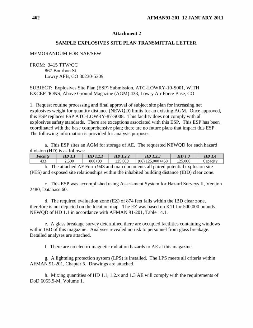
462 AFMAN91-201 12 JANUARY 2011
Attachment 2
SAMPLE EXPLOSIVES SITE PLAN TRANSMITTAL LETTER.
MEMORANDUM FOR NAF/SEW
FROM: 3415 TTW/CC
867 Bourbon St
Lowry AFB, CO 80230-5309
SUBJECT: Explosives Site Plan (ESP) Submission, ATC-LOWRY-10-S001, WITH
EXCEPTIONS, Above Ground Magazine (AGM) 433, Lowry Air Force Base, CO
1. Request routine processing and final approval of subject site plan for increasing net
explosives weight for quantity distance (NEWQD) limits for an existing AGM. Once approved,
this ESP replaces ESP ATC-LOWRY-87-S008. This facility does not comply with all
explosives safety standards. There are exceptions associated with this ESP. This ESP has been
coordinated with the base comprehensive plan; there are no future plans that impact this ESP.
The following information is provided for analysis purposes.
a. This ESP sites an AGM for storage of AE. The requested NEWQD for each hazard
division (HD) is as follows: Facility HD 1.1 HD 1.2.1 HD 1.2.2 HD 1.2.3 HD 1.3 HD 1.4
433 2,500 800<99 125,000 (06) 125,000<450 125,000 Capacity
b. The attached AF Form 943 and map documents all paired potential explosion site
(PES) and exposed site relationships within the inhabited building distance (IBD) clear zone.
c. This ESP was accomplished using Assessment System for Hazard Surveys II, Version
2480, Database 60.
d. The required evaluation zone (EZ) of 874 feet falls within the IBD clear zone,
therefore is not depicted on the location map. The EZ was based on K11 for 500,000 pounds
NEWQD of HD 1.1 in accordance with AFMAN 91-201, Table 14.1.
e. A glass breakage survey determined there are occupied facilities containing windows
within IBD of this magazine. Analyses revealed no risk to personnel from glass breakage.
Detailed analyses are attached.
f. There are no electro-magnetic radiation hazards to AE at this magazine.
g. A lightning protection system (LPS) is installed. The LPS meets all criteria within
AFMAN 91-201, Chapter 5. Drawings are attached.
h. Mixing quantities of HD 1.1, 1.2.x and 1.3 AE will comply with the requirements of
DoD 6055.9-M, Volume 1.
AFMAN91-201 12 JANUARY 2011 463
i. This ESP has been coordinated with all applicable agencies. There are no tenant units
exposed by this magazine.
2. There are two paired relationships where QD criteria cannot be met. Use of compensatory
measures cannot negate these exceptions. As a result, there are two exemptions, NAF-LOWRY-
10-E01 and ATC-LOWRY-10-E01, that require NAF and MAJCOM approval respectively. All
information pertaining to these exceptions are contained in the attached nomographs.
3. Should you have additional questions or concerns, please contact 3415 TTW/SEW, at DSN:
926-2666 or email: [email protected].
ELISHA A. MANNING III, Col, USAF
Commander
6 Attachments:
1. AF Form 943
2. Location Map
3. LPS Drawings
4. Glass Breakage Analyses
5. NAF-LOWRY-10-E01, Exception Decision Nomograph and Narrative
6. ATC-LOWRY-10-E01, Exception Decision Nomograph and Narrative
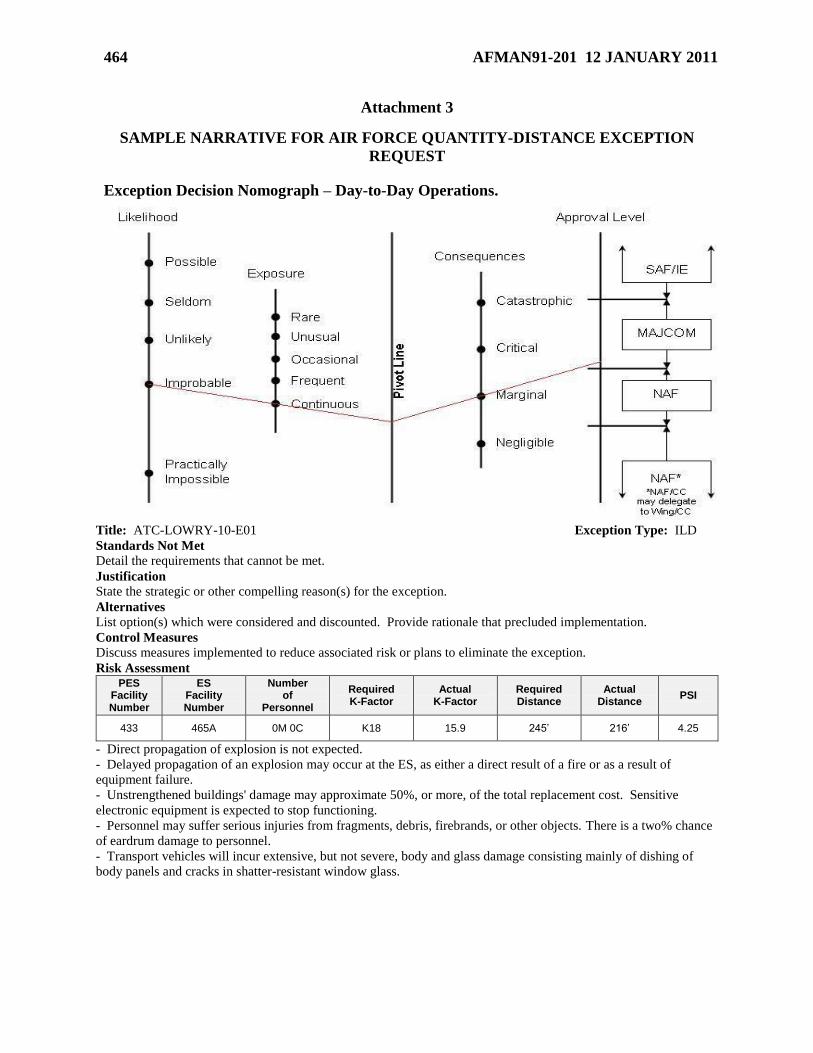
464 AFMAN91-201 12 JANUARY 2011
Attachment 3
SAMPLE NARRATIVE FOR AIR FORCE QUANTITY-DISTANCE EXCEPTION
REQUEST
Exception Decision Nomograph – Day-to-Day Operations.
Title: ATC-LOWRY-10-E01 Exception Type: ILD
Standards Not Met
Detail the requirements that cannot be met.
Justification
State the strategic or other compelling reason(s) for the exception.
Alternatives
List option(s) which were considered and discounted. Provide rationale that precluded implementation.
Control Measures
Discuss measures implemented to reduce associated risk or plans to eliminate the exception.
Risk Assessment PES
Facility Number
ES Facility Number
Number of
Personnel
Required K-Factor
Actual K-Factor
Required Distance
Actual Distance
PSI
433 465A 0M 0C K18 15.9 245’ 216’ 4.25
- Direct propagation of explosion is not expected.
- Delayed propagation of an explosion may occur at the ES, as either a direct result of a fire or as a result of
equipment failure. - Unstrengthened buildings' damage may approximate 50%, or more, of the total replacement cost. Sensitive
electronic equipment is expected to stop functioning.
- Personnel may suffer serious injuries from fragments, debris, firebrands, or other objects. There is a two% chance
of eardrum damage to personnel.
- Transport vehicles will incur extensive, but not severe, body and glass damage consisting mainly of dishing of
body panels and cracks in shatter-resistant window glass.
AFMAN91-201 12 JANUARY 2011 465
ATTACHMENT 4
SELECTED SECRETARY OF THE AIR FORCE EXEMPTIONS
(Some offices and symbols have changed)
Figure A4.1.
MEMORANDUM FOR AF/SE
SUBJECT: SECAF Exemption to Explosives Quantity-Distance Standards at Aviano AB
Allowing for Construction of a US Army Heavy Drop Rigging Complex
Commanders in United States Air Forces in Europe and United States Army Europe are required
to enhance the support of joint DoD operations during times of contingency. To this end, the US
Army has asked to build a new Heavy Drop Rigging Complex (HDRC) at Aviano AB to enhance
173rd
Airborne Brigade deployment activities. The proposed eight construction projects
associated with this complex are less than the required explosives quantity-distance separation
standards prescribed in DoD 6055.09-M and AFMAN 91-201 for 44 paired relationship
explosives safety evaluations.
The departures from the safety standards involve insufficient separation between the proposed
structures and the installation boundary and between USAF and USA explosives and non-
explosives locations. The most serious of these departures is to the base boundary. Italian
civilians in fields adjacent to the base boundary are at risk of death should an explosive mishap
occur at either of the US Army HDRC explosives structures. Although the fields adjacent to the
base boundary are currently used for agriculture, and are infrequently occupied by civilians,
residential or business development of this land would increase the number of civilians in harm’s
way. It is my understanding, however, that a restrictive easement has been approved by the
Italian regional panel limiting civilian exposure to risk by freezing use of the land at current
levels, and prohibiting future development.
After due consideration, I find that compelling operational requirements necessitate deviation
from Department of Defense Explosives Quantity-Distance standards with regard to the location
of a new US Army HDRC at Aviano AB. Based on the concurrence provided by the highest US
Army approval authority for explosives safety exemptions, DASA (I & E), and the absence of
viable alternatives, I conclude that exemptions for the US Army HDRC are appropriate, and
approve the start of this US Army-funded project.
I hereby approve the exemptions for the eight US Army HDRC locations. Permanent copies of
this memorandum will be maintained at AFSC, USAFE, and Aviano AB. This exemption will
be reviewed every five years at the appropriate level for the continued use of this exception in
accordance with AFMAN 91-201 and to verify the continued accuracy of the risk assessment
provided.
466 AFMAN91-201 12 JANUARY 2011
Figure A4.2.
MEMORANDUM FOR AF/SE
SUBJECT: SECAF Exemption to Explosives Quantity-Distance Standards at Osan AB
Allowing for Construction of Fighter Squadron Operations/ Aircraft Maintenance Facility
Addition
Commanders in Korea have a requirement to enhance the support of combat aircraft operations
during times of contingency and wartime operations. As a result, the expansion of aircraft
support facility 1702 is required to enhance the 51st Fighter Wing’s ability to maintain combat
assets.
Based on the proposed expansion location and its proximity to three nearby 3rd
generation
hardened aircraft shelters, the required explosives quantity-distance separation standards as
prescribed in AFMAN 91-201 are not met. As a result, personnel and assets located in the
facility could be subjected to blast overpressure and fragmentation far in excess of those
prescribed during exercise and contingency operations. Should a mishap occur at the closest of
the three aircraft shelters, consequences to the building 1702 expansion could include up to five
fatalities, serious injuries, mission interruption, and up to $500,000 in damage.
I have weighed the need for the need for the 25th
fighter squadron operations/aircraft
maintenance facility expansion at Osan AB against the expected impact in the event of a mishap.
In the absence of available alternatives, I conclude that an exemption for the construction of the
aircraft support facility expansion is appropriate, and approve the expenditure of construction
funds.
Permanent copies of this memorandum will be maintained at AFSC, HQ PACAF, and Osan AB.
This exemption will be reviewed every five years at the appropriate level for the continued use of
this exception in accordance with AFMAN 91-201.
AFMAN91-201 12 JANUARY 2011 467
Attachment 5
QD GUIDANCE FOR ON-BASE ROADS
A5.1. In order to prevent the generation of a significant number of quantity-distance
exemptions, DoD 6055.09-M requirements allow the DoD components to establish procedures
for assessing, documenting, and accepting the risks associated with application of QD criteria to
on-base roads for on-base road relationships which existed prior to 1 Oct 00. QD criteria is
based on the traffic density (PTR or IBD). After 1 Oct 00, any changes to a PES which increase
its QD arc, construction of a new PES, or construction of a new on-base road, will require
application of QD criteria to on-base roads which are traveled by personnel not involved in
munitions related operations. If QD criteria cannot be met, the formal exemption requirements
of AFMAN 91-201 must be followed.
A5.2. For those sited (DDESB- or AFSC-approved or MAJCOM baseline-approved) PES/on-
base road relationships which existed prior to 1 Oct 00, we require the following risk assessment
and documentation be accomplished:
A5.2.1. On a copy of the installation map, identify the following:
A5.2.1.1. All PESs having QD arcs (PTR or IBD based on traffic density) encompassing
on-base roads traveled by personnel not involved in munitions-related operations.
A5.2.1.2. The Net Explosives Weight for Quantity-Distance (NEWQD) of the above
PESs.
A5.2.1.3. The applicable QD arcs (PTR or IBD) of the above PESs based on the traffic
density.
A5.2.1.4. The segments of the applicable on-base roads which pass through the above
arcs.
A5.2.2. Perform a risk assessment of the relationships shown above in accordance with Risk
Management procedures. Some factors that might be considered include:
A5.2.2.1. Operational necessity.
A5.2.2.2. The operation being performed (e.g., static storage, maintenance, and
production).
A5.2.2.3. Operational activity cycles.
A5.2.2.4. Alternate routes.
A5.2.2.5. Traffic density.
A5.2.2.6. Accident records.
A5.2.2.7. Time interval of exposure.
A5.2.2.8. Type and quantity of munitions in proximity to the area transited.
A5.2.2.9. The closest distance from the area transited to the PES.
A5.2.2.10. The need for installation-related personnel to transit the ESQD arc.
468 AFMAN91-201 12 JANUARY 2011
A5.2.3. Document the commander’s risk acceptance through a formal memorandum and
review upon change of the approval authority. This memorandum must include the map
showing the relationships for which he/she is accepting risk, a summary of the risk
assessment, and a statement that the subject relationships existed as of 1 Oct 00.
A5.3. It is highly recommended that the above risk assessment and documentation be
accomplished to accurately capture the relationships, which existed as of 1 Oct 00, and to avoid
DDESB survey findings. The commander’s risk acceptance and attached map must be included
in amendments to site plans (for PESs which existed prior to 1 Oct 00), or referenced if
previously submitted with another site plan amendment, which do not increase the QD arc. As
stated previously, after 1 Oct 00, any changes to a PES which increase its QD arc, construction
of a new PES, construction of a new on-base road, or increased traffic density will require
application of QD criteria to on-base roads which are traveled by personnel not involved in
munitions related operations (see paragraph 12.16.)
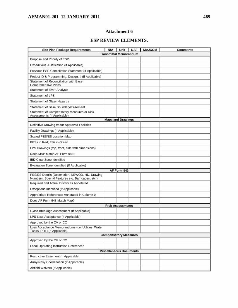
AFMAN91-201 12 JANUARY 2011 469
Attachment 6
ESP REVIEW ELEMENTS.
Site Plan Package Requirements N/A Unit NAF MAJCOM Comments
Transmittal Memorandum
Purpose and Priority of ESP
Expeditious Justification (If Applicable)
Previous ESP Cancellation Statement (If Applicable)
Project ID & Programming, Design, # (If Applicable)
Statement of Reconciliation with Base Comprehensive Plans
Statement of EMR Analysis
Statement of LPS
Statement of Glass Hazards
Statement of Base Boundary/Easement
Statement of Compensatory Measures or Risk Assessments (If Applicable)
Maps and Drawings
Definitive Drawing #s for Approved Facilities
Facility Drawings (If Applicable)
Scaled PES/ES Location Map
PESs in Red; ESs in Green
LPS Drawings (top, front, side with dimensions)
Does MAP Match AF Form 943?
IBD Clear Zone Identified
Evaluation Zone Identified (If Applicable)
AF Form 943
PES/ES Details (Description, NEWQD, HD, Drawing Numbers, Special Features e.g. Barricades, etc.)
Required and Actual Distances Annotated
Exceptions Identified (If Applicable)
Appropriate References Annotated in Column 9
Does AF Form 943 Match Map?
Risk Assessments
Glass Breakage Assessment (If Applicable)
LPS Loss Acceptance (If Applicable)
Approved by the CV or CC
Loss Acceptance Memorandums (i.e. Utilities, Water Tanks, POL) (If Applicable)
Compensatory Measures
Approved by the CV or CC
Local Operating Instruction Referenced
Miscellaneous Documents
Restrictive Easement (If Applicable)
Army/Navy Coordination (If Applicable)
Airfield Waivers (If Applicable)
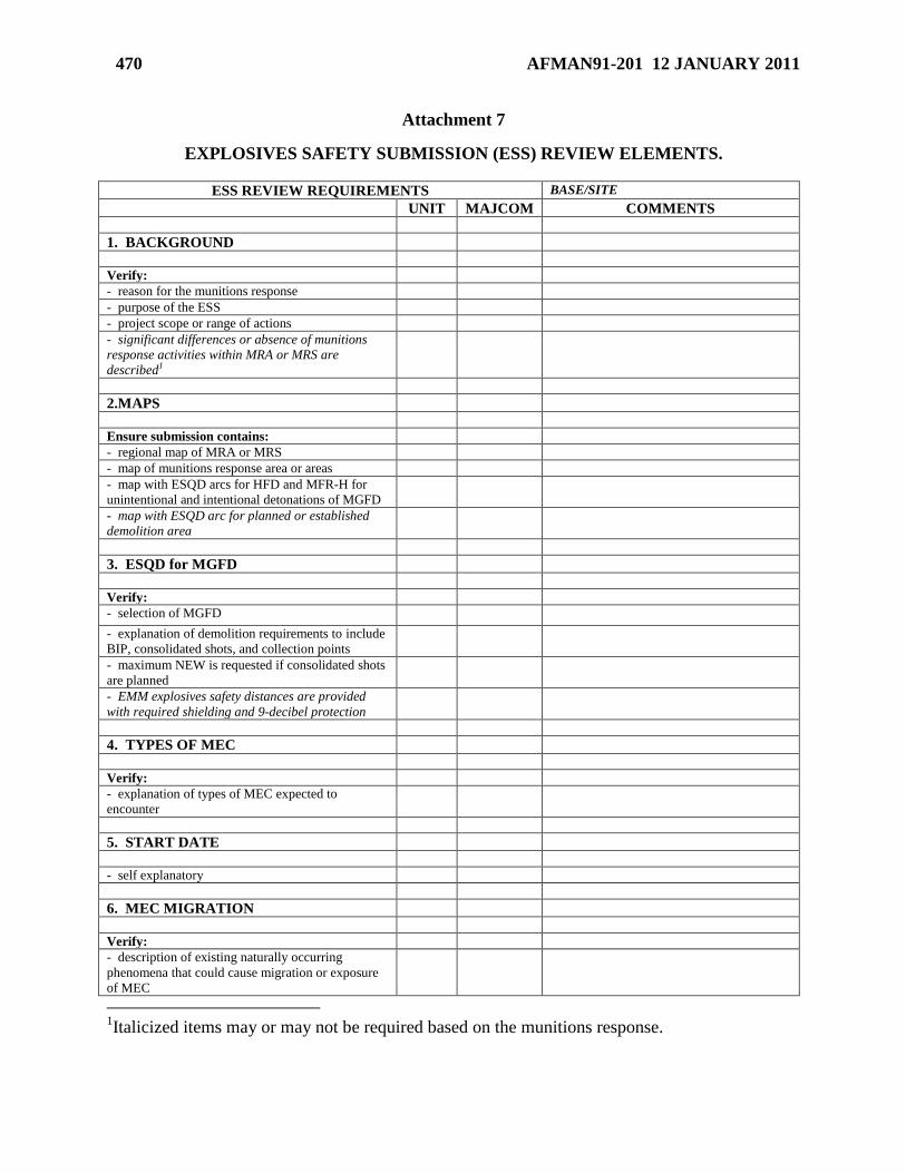
470 AFMAN91-201 12 JANUARY 2011
Attachment 7
EXPLOSIVES SAFETY SUBMISSION (ESS) REVIEW ELEMENTS.
ESS REVIEW REQUIREMENTS BASE/SITE
UNIT MAJCOM COMMENTS
1. BACKGROUND
Verify:
- reason for the munitions response
- purpose of the ESS
- project scope or range of actions
- significant differences or absence of munitions
response activities within MRA or MRS are
described1
2.MAPS
Ensure submission contains:
- regional map of MRA or MRS
- map of munitions response area or areas
- map with ESQD arcs for HFD and MFR-H for
unintentional and intentional detonations of MGFD
- map with ESQD arc for planned or established
demolition area
3. ESQD for MGFD
Verify:
- selection of MGFD
- explanation of demolition requirements to include
BIP, consolidated shots, and collection points
- maximum NEW is requested if consolidated shots
are planned
- EMM explosives safety distances are provided
with required shielding and 9-decibel protection
4. TYPES OF MEC
Verify:
- explanation of types of MEC expected to
encounter
5. START DATE
- self explanatory
6. MEC MIGRATION
Verify:
- description of existing naturally occurring
phenomena that could cause migration or exposure
of MEC
1Italicized items may or may not be required based on the munitions response.

AFMAN91-201 12 JANUARY 2011 471
- procedure for monitoring/managing migration of
MEC is provided
7. DETECTION EQUIPMENT AND
RESPONSE TECHNIQUES
Verify:
- techniques for detection and removal of MEC are
outlined
- types of detection equipment and areas of use are
explained
- methods to establish expected detection
capabilities are addressed, to include rationale for
use and limitations of detection methods
- exclusion zone procedures are described
- QA/QC standards are described
8. DISPOSITION TECHNIQUES
Verify:
- planned engineering controls are adequately
described
- disposition techniques (e.g., OB, OD, BIP,
consolidated shots, incineration), if not previously
explained, are described
- scrap determination and disposition procedures
are covered
9. ENVIRONMENTAL, ECOLOGICAL,
CULTURAL, AND OTHER
CONSIDERATIONS
Verify:
- environmental, ecological, and cultural factors
that impact the selected munitions response are
addressed
10. TECHNICAL SUPPORT
Verify:
- any required UXO-technician or EOD support is
provided
11. RESIDUAL RISK MANAGMENT
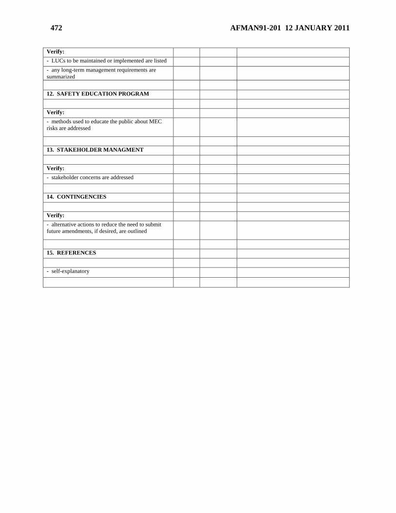
472 AFMAN91-201 12 JANUARY 2011
Verify:
- LUCs to be maintained or implemented are listed
- any long-term management requirements are
summarized
12. SAFETY EDUCATION PROGRAM
Verify:
- methods used to educate the public about MEC
risks are addressed
13. STAKEHOLDER MANAGMENT
Verify:
- stakeholder concerns are addressed
14. CONTINGENCIES
Verify:
- alternative actions to reduce the need to submit
future amendments, if desired, are outlined
15. REFERENCES
- self-explanatory
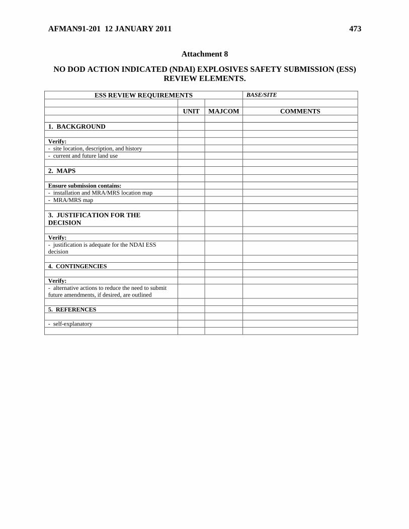
AFMAN91-201 12 JANUARY 2011 473
Attachment 8
NO DOD ACTION INDICATED (NDAI) EXPLOSIVES SAFETY SUBMISSION (ESS)
REVIEW ELEMENTS.
ESS REVIEW REQUIREMENTS BASE/SITE
UNIT MAJCOM COMMENTS
1. BACKGROUND
Verify:
- site location, description, and history
- current and future land use
2. MAPS
Ensure submission contains:
- installation and MRA/MRS location map
- MRA/MRS map
3. JUSTIFICATION FOR THE
DECISION
Verify:
- justification is adequate for the NDAI ESS
decision
4. CONTINGENCIES
Verify:
- alternative actions to reduce the need to submit
future amendments, if desired, are outlined
5. REFERENCES
- self-explanatory