by order of the commander afsoc … · afpd 11-2, flight rules and procedures. ... 2.8 descent ......
TRANSCRIPT

BY ORDER OF THE COMMANDER AFSOC INSTRUCTION 11-202, VOLUME 17AIR FORCE SPECIAL OPERATIONS COMMAND 1 JUNE 1997
Flying Operations
EC-130 EMPLOYMENT____________________________________________________________________________________COMPLIANCE WITH THIS INSTRUCTION IS MANDATORY. This instruction implementsAFPD 11-2, Flight Rules and Procedures. It establishes employment procedures for AFSOC EC-130aircraft and aircrew. It applies to all AFSOC EC-130 aircrews. It applies to the Air National Guard(ANG) when published in the ANGIND 2.
OPR: HQ AFSOC/DOVF (Capt Wallace), 193 SOW/OGV (Maj McCarthy)Certified by: HQ AFSOC/DOV (Col Garlington)Pages: 33Distribution: F; X
Chapter 1 -- E-130E Employment Procedures Paragraph
Section A -- Employment ConceptGeneral .........................................................................................................................1.1Mission .........................................................................................................................1.2Communications and Operations Security (COMSEC and OPSEC) ...............................1.3Crew Rest .....................................................................................................................1.4Checklists/Inflight Guides..............................................................................................1.5Definitions ....................................................................................................................1.6
Section B -- Mission Planning and Employment ProceduresMission Feasibility ........................................................................................................1.7Mission Planning...........................................................................................................1.8Threat Analysis and Degradation ...................................................................................1.9Route Selection .............................................................................................................1.10Altitude and Airspeed ....................................................................................................1.11Fuel Planning ................................................................................................................1.12Air Refueling.................................................................................................................1.13Due Regard Operations .................................................................................................1.14Communications............................................................................................................1.15
Section C -- Mission Orbit ProceduresGeneral .........................................................................................................................1.16Mission Planning...........................................................................................................1.17Altitude and Airspeed ....................................................................................................1.18Fuel Planning ................................................................................................................1.19Air Refueling.................................................................................................................1.20Chart Preparation..........................................................................................................1.21
Section D -- Ingress/Egress ProceduresGeneral .........................................................................................................................1.22Mission Planning...........................................................................................................1.23Altitude and Airspeed ....................................................................................................1.24Time Control Procedures ...............................................................................................1.25

AFSOCI 11-202 Volume 17 1 June 1997 2
Fuel Planning ................................................................................................................1.26Air Refueling.................................................................................................................1.27Chart Preparation..........................................................................................................1.28
Section E -- Emergency Egress ProceduresMission Preparation ......................................................................................................1.29Route ............................................................................................................................1.30Altitude.........................................................................................................................1.31Airspeed........................................................................................................................1.32Chart Preparation ..........................................................................................................1.33Fuel Planning ................................................................................................................1.34Course Maneuvering .....................................................................................................1.35Energy Management......................................................................................................1.36Threat Maneuvering ......................................................................................................1.37
Section F -- Chart PreparationGeneral .........................................................................................................................1.38Annotations and Symbols ..............................................................................................1.39
Section G -- Flight Crew DutiesGeneral .........................................................................................................................1.40Crew duties ...................................................................................................................1.41
Chapter 2 -- General Operating Guidelines
Section A -- Standard ProceduresGeneral .........................................................................................................................2.1Command and Control...................................................................................................2.2Mission Planning...........................................................................................................2.3
Section B -- Standard Operating ProceduresGeneral .........................................................................................................................2.4Ground Operations ........................................................................................................2.5Takeoff and Departure...................................................................................................2.6Cruise ...........................................................................................................................2.7Flight Operations at Tactical Altitudes...........................................................................2.8Descent .........................................................................................................................2.9Approach and Landing ..................................................................................................2.10Engine Shutdown...........................................................................................................2.11Debriefings ...................................................................................................................2.12
Section C -- Engine Running Crew Change ProceduresGeneral .........................................................................................................................2.13Engine Running Offload (ERO).....................................................................................2.14
Section D -- Restrictions and LimitationsGeneral .........................................................................................................................2.15Aircraft Operations Restrictions ....................................................................................2.16Tactical Altitude Flight Restrictions...............................................................................2.17National Guard Bureau Restrictions ..............................................................................2.18
Figures Page1.1 Radius of Turn for 20 Degrees of Bank................................................................... 151.2 Radius of Turn for 30 Degrees of Bank................................................................... 16

AFSOCI 11-202 Volume 17 1 June 1997 3
1.3 EC-130 Chart Preparation Guide ............................................................................ 18
Attachments1. ERO Abbreviated Checklist ...................................................................................... 292. Combat Checklists.................................................................................................... 31
Related information found in the 193rd Tactics Pamphlet (S):1. Threat radar systems2. Surface to air missiles (SAMs)3. Anti-Aircraft Artillery (AAA)4. Airborne Interceptors (AI)5. Aircraft Defensive Systems (ADS)
CHAPTER 1
EC-130E EMPLOYMENT PROCEDURES
Section A -- Employment Concept
1.1. General. Commando Solo and Senior Scout operations may be long or short range missions withextended orbit delays planned at the aircraft operating ceiling, and may require one or multiple airrefuelings. Some missions may require a combat profile, with a low altitude profile enroute to the missionorbit area. In threat areas, no specific set of en route tactics can be selected as a best profile. Chapter 1section B provides general information on the employment of the EC-130E, while sections C, D, E, and Fprovide more detailed information in the areas of mission orbits, ingress/egress routes, emergency egressroutes, and chart preparation. Refer to AFSOCMAN 11-1, Vol 5, (S) Tactical Employment, EC-130E,Commando Solo (U), for detailed information on threat avoidance and tactics procedures for the EC-130E.
1.2. Mission. The EC-130E Commando Solo aircraft is capable of conducting day/night overt or covertbroadcasts on AM/FM radio, TV, HF/Shortwave, and tactical military communications frequenciessimultaneously while loitering outside the lethal range of threat systems located in hostile territories.
1.3. Communications and Operations Security (COMSEC and OPSEC). Security is vital to alloperations conducted in accordance with (IAW) this chapter. The electronic environment may be hostile,with enemy ability to jam all communications radios and electronic transmission systems; to intercept anduse intelligence information transmitted over nonsecure electronic systems and radios; and to pinpoint theposition of the aircraft emitting any electronic transmission or signal. Consideration of OPSEC must beapplied to all phases of mission planning and execution to avoid compromise of mission objectives.
1.4. Crew Rest. Crews may expect long crew days and austere crew rest facilities that are not conduciveto normal crew rest. Additionally, multiple time zone crossings and abrupt changes of circadian rhythmincrease crew fatigue. The ability of crews to get uninterrupted sleep is crucial to flight safety andultimately mission success. Planners and supervisors must exercise extreme caution regarding crew rest. If possible, a flight surgeon should accompany the deployment as part of the staff package duringcontingency operations or exercises. HQ AFSOC/SG may authorize use of sedatives or stimulants throughthe unit or exercise flight surgeon.
1.5. Checklists/Inflight Guides. Expanded checklist information is included in applicable attachments tothis volume. The flight engineer reads all combat/tactical checklists unless briefed otherwise by the aircraftcommander. Checklist items not applicable to the aircraft, mission or profile being flown need not bechallenged nor responded to (e.g., ALE-40 - "ARMED/SAFE" need not be challenged if Chaff and Flaresare not loaded).

AFSOCI 11-202 Volume 17 1 June 1997 4
1.6. Definitions. The following definitions are to be used in planning procedures and discussions of themission:
1.6.1. Airborne Mission Commander (AMC). The designated airborne commander of joint missionelements. Do not confuse with the search and rescue (SAR) Airborne Mission Coordinator.
1.6.2. Airborne Mission Supervisor (AMS). (Senior Scout Only) The senior ranking crewmember of theSenior Scout mission crew, and focal point for coordination between the mission and flight crews.
1.6.3. AN/AAR-44. Detects missile exhaust plumes, issues alarms and indications when they aredetected.
1.6.4. AN/ALE-40. Flare and chaff dispensing system which deceives infrared (IR) and radar guidedthreats.
1.6.5. AN/ALQ-157. System which deceives certain infrared (IR) guided threats.
1.6.6. AN/ALR-69 Radar warning receiver (RWR). Provides video and audio alerts to the crew whenthe system detects threat radar signals.
1.6.7. Air Tasking Order (ATO). In some theaters the ATO is included in an Integrated Tasking Order(ITO) which includes ground and naval tasking.
1.6.8. Brevity Code. Codewords or acronyms used to identify mission elements or execution directions.
1.6.9. CEOI. Communications electronics operating instructions.
1.6.10. Cookie cutter distances. The maximum effective range of a specific threat, without taking intoaccount the altitude capabilities or effects of terrain masking.
1.6.11. Corridor. A real or imaginary barrier defining the outer maneuvering limits for a flight plan leg.
1.6.12. Crew (EC-130):
1.6.12.1. Air Crew. Includes all flight and mission crew members required to employ the EC-130 mission.
1.6.12.2. Flight Crew. Consists of the pilot, copilot, navigator, flight engineer, and loadmaster. Does notinclude the Commando Solo or Senior Scout electronic mission specialists.
1.6.12.3. Mission Crew. The Commando Solo or Senior Scout electronic mission specialists. Does notinclude the flight crew consisting of the pilot, copilot, navigator, flight engineer, and loadmaster.
1.6.13. D-Day. The day mission operations commence.
1.6.14. Detection Free Altitude (DFA). The maximum altitude which will provide terrain masking fromall known or suspected radar, IR and optical guided threats along each route segment.
1.6.15. Due Regard. Military flight operations including, but not limited to, military contingencies,politically sensitive, classified, and/or combat missions which do not conform to ICAO procedures may beconducted under the “Due Regard” or “Operational” prerogative for military aircraft. Due Regardobligates the military aircraft commander to be his own Air Traffic Control agency and separate hisaircraft from all other air traffic. The aircraft shall, be under radar surveillance with radio communicationsof an airborne or surface radar facility, or be equipped with onboard radar which provides for a level ofsafety equivalent to that normally given by ICAO Air Traffic Control agencies; or be operating in VisualMeteorological Conditions. (Ref: FLIP, GP)
1.6.16. Execution Checklist. A chronological listing of key employment/deployment events provided bythe user to monitor mission progress.
AFSOCI 11-202 Volume 17 1 June 1997 5
1.6.17. EEFI. Essential elements of friendly information.
1.6.18. Emergency Egress Point (EEP). A navigation checkpoint on the planned egress route andoutside the lethal range of all enemy threat systems.
1.6.19. Emergency Safe Altitude (ESA). An altitude computed by adding 1,000 feet (2,000 feet inmountainous terrain) to the highest elevation/obstacle within 22 NM of centerline or planned flight path,whichever is greater, and rounded up to the next 100 - foot increment. ESA provides a safe altitude whichensures terrain clearance. A single ESA will be established for the entire route when there are nosignificant changes in topography. For routes where the terrain does vary significantly, a separate ESAmay be established for route segments with similar terrain or obstacle elevations.
WARNING: Operation under VFR clearance in IMC conditions is an emergency procedure duringtraining/ exercise operations, requiring appropriate IFF and radio calls to the area air traffic controlagency. During contingency/combat missions, the necessity of flying "comm-out" in IMC must be weighedagainst terrain clearance capability and increased mid-air potential.
1.6.20. Flight Commander. The designated leader of two or more flights of aircraft.
1.6.21. Ground Commander. The designated on-ground commander of joint forces elements.
1.6.22. H-Hour. The specific hour on D-Day on which hostilities commence. When used in conjunctionwith planned operations, it is the specific hour on which the operation commences.
1.6.23. HAVE QUICK. Nonsecure, jam-resistant UHF radio system.
1.6.24. Highest Terrain or Obstacle (HTO). The highest terrain or obstacle for a flight plan leg or legsegment.
1.6.25. Infrared (IR). Lying outside the visible light spectrum limit just below the frequency associatedwith visible red. Visible to IR guided missile seeker heads and to the human eye only when utilizing NVGs.
1.6.26. Joint Operations Commander (JOC). The designated operational commander of all assetscommitted to one particular joint operation.
1.6.27. KY-58. Secure speech system (VINSON) associated with the FM, UHF, VHF, and satellitecommunications (SATCOM) systems.
1.6.28. KY-75. Secure speech system (PARKHILL) associated with wide-band HF radio.
1.6.29. KYV-5. Secure speech system associated with narrow-band HF radio.
1.6.30. L-Hour. The time of landing of the first wave of assault aircraft.
1.6.31. Line of Communication (LOC). Any road, river, power line, etc., which has the probability ofbeing traveled along or monitored by hostile forces.
1.6.32. Lowest Acceptable Altitude (LAA). The lowest altitude that a specific crew and specificallyconfigured aircraft may fly.
1.6.33. M206 Flares. High-intensity pyrotechnics installed in the AN/ALE-40 ejector cases which aredesigned to confuse enemy infrared (IR) missile guidance systems. The most common type of flares usedon C-130s.
1.6.34. Minimum Safe Altitude (MSA). MSA is computed at 1,000 feet above HTO within five NM ofcenterline or planned flight path, whichever is greater, and rounded up to the next 100-foot increment. MSA is an intermediate altitude which will provide terrain clearance yet limit threat detection duringsituations that require leaving the low level structure.

AFSOCI 11-202 Volume 17 1 June 1997 6
1.6.35. Modified Contour. Flight involving vertical and horizontal movement of the aircraft by means ofboth radar altimeter and visual references, in an attempt to maintain a specific AGL altitude over terrain ofvarying elevation. Momentary deviations below the specified modified contour altitude can be expecteddue to altimeter lag and other factors. Example: 500 ft modified contour.
1.6.36. Noise Sensitive Areas (NSA). Areas along training routes identified as having a high number ofnoise complaints. Avoid designated NSAs by 3 NM or cross no lower than 1500’ AGL, or as published.
1.6.37. Reference Heading. The magnetic course between two waypoints used to aid in dead reckoningduring significant turns on tactical flights.
1.6.38. Rendezvous. A procedure to join-up two or more aircraft in aerial flight.
1.6.39. RR-170 Chaff. Metallized MYLAR strips installed in the AN/ALE-40 ejector cases which aredesigned to deceive and confuse enemy acquisition and guidance radar systems.
1.6.40. Rules of Engagement (ROE). Directives issued by competent military authority which delineatethe circumstances and limitations under which US forces will initiate, continue, and/or terminate combatengagements with other forces.
1.6.41. SAFE Area. "Selected Areas for Evasion" used in conjunction with escape and evasion (E&E)procedures during SAR operations.
1.6.42. Special Instructions (SPINS). Associated with the ATO. Provides detailed, non mission specificinformation on general operating procedures in the theater.
1.6.43. Tactical Altitude. A general description for altitude on those flights where the cruising altitude isat or below the ESA, or when modified contour procedures are used.
1.6.44. Terrain Masking. Using the terrain to avoid radar, IR or visual detection.
1.6.44.1. Direct terrain masking is maneuvering the aircraft to place the terrain between you and thethreat.
1.6.44.2. Indirect terrain masking is having the aircraft so close to the terrain that it is very difficult todistinguish the aircraft from the background. Indirect terrain masking is ineffective against pulsed Dopplerradar or moving target indicator equipped threats.
Section B - Mission Planning and Employment Procedures
1.7. Mission Feasibility. Prior to conducting comprehensive mission planning, a planning staff(consisting of representatives of applicable crew positions) will determine if the mission can be completedIAW AFSOCR 55-6. This must be accomplished as rapidly as possible since the mission feasibility resultswill determine the "go" or "no go" decision of the tasking agency. The 193 SOW mission planning foldershould be used as a guide for this process, and include a comprehensive risk assessment.
1.8 Mission Planning:
1.8.1. General. The successful execution of a mission depends in large measure upon comprehensivepremission planning. For missions requiring a long crew duty day or operations at tactical altitudes,mission planning will be completed prior to entering crew rest. Flight planning emphasis should be placedon the environment at least 60 nautical miles either side of the intended mission orbit delay area andingress/egress flight path (30 NM for operations at tactical altitudes) to include terrain features, lines ofcommunications, population centers and threat areas. In addition to aircraft and mission equipmentcapabilities/limitations, terrain, and threat factors; planners must honor claimed airspace limits of sovereign

AFSOCI 11-202 Volume 17 1 June 1997 7
nations and take into account the political climate in the region. All other factors consistent, peace timecontingency operations will place emphasis on respect for sovereign national boundaries. If low altitudeingress/egress route segments are required, they should be planned and flown at the highest possiblealtitude that minimizes detection.
WARNING: Mixing of multiple coordinate datums can cause significant navigational and target errors onEC-130 missions. The consistent use of the same datum for all coordinates will greatly reduce these errors.Ensure the same datum is used to derive coordinates for SCNS initialization, turnpoints, air refuelingtracks, mission orbits, and targets. Currently the emphasis is to convert all charts when possible to theWGS-84 standard.
1.8.2. Computer Flight Planning. FPlan is currently the computer flight planning program approved forAFSOC EC-130 planning operations. The Portable Flight Planning System (PFPS) will be replacingFPlan with expanded capabilities. For detailed mission planning and analysis the Special Operations FlightPlanning and Rehearsal System (SOFPARS) provides detailed mission planning capabilities.
1.9. Threat Analysis and Degradation. Missions flown in or near a hostile environment should expect toencounter enemy opposition from surface-based defenses and enemy aircraft. Employment planners andmission commanders must be prepared to plan and employ tactics which minimize the effects of thesethreats. EC-130 Senior Scout and Commando Solo missions will be planned to avoid all known threats. Crews should be thoroughly familiar with the 193 SOW Mission Planning Guide, Mission Planning Folder,Tactics Pamphlet, AFSOCMAN 11-1, Volumes 2 and 5, Threat Analysis, and Risk AssessmentProcedures, respectively.
1.9.1. Threat Factors:
1.9.1.1. The adversaries’ threat system employment doctrine.
1.9.1.2. Effective operating range, types of armament, and employment tactics of air intercept aircraft.
1.9.1.3. Mobility of ground and naval systems. Not only could a system be moved to intercept theproposed mission track, but traverse rates may allow continued engagement.
1.9.1.4. Accuracy of the guidance or optics. The age of the system and its low level capability are factors.
1.9.1.5. Range of the weapon. Actual range of the weapon is usually given as maximum effective range. The minimum range also may be a factor. Also known as lethal range.
1.9.1.6. Range of the acquisition radar. The distance or length of time that the radar will track the aircraftbefore it is within lethal range.
1.9.1.7. Command and Control. The authority for firing the weapon may be far removed from the weaponlocation. Intelligence should determine who is the firing authority and how long it would take for theweapon system to receive the firing command.
1.9.1.8. Accuracy of the weapon. The accuracy may vary with the altitude, the speed of the aircraft, andthe distance the aircraft is from the weapon. Age and condition (maintenance readiness) will also befactors.
1.9.1.9. Day versus night operations. Some systems may not be manned at night. Further, light conditionsmay affect optics and infrared guidance.
1.9.1.10. Number of missiles and rate of fire. The number of missiles that could be fired and at whatinterval; the practical rate of fire for AAA and the reload time.
AFSOCI 11-202 Volume 17 1 June 1997 8
1.9.1.11. Weather limitations. Moisture, heat, cold, wind limitations, electrical storms, temperatureinversions, and clouds could all be factors, affecting not only the weapon, but also the personnel controllingthe weapon.
1.9.2. Detection Factors:
1.9.2.1. Direction Finding capability.
1.9.2.2. Passive or acoustical detection devices.
1.9.2.3. Ground or sea observation posts or networks.
1.9.2.4. LOCs, especially at points such as dams, bridges, and road intersections.
1.9.2.5. Military maneuvers and exercises, including aircraft training routes.
1.9.2.6. Boats and ships, including commercial or fishing vessels. Associated threats include visual andradar detection. Modern military vessels have sophisticated anti-aircraft detection and defense suites.
1.9.2.7. Festival, holiday, or vacation gathering places.
1.9.2.8. Satellite schedules. This has become a significant threat in both the visual and electronicspectrum.
1.9.2.9. Radar. Flights should be planned through areas that preclude radar detection, including airportapproach and air route traffic control radar coverage. Modern radar has three significant vulnerabilitiesthat should be exploited during mission planning. These are: limits on maximum range, degraded low leveldetection capabilities because of the earth's curvature (radar horizon distance (RHD)), and the maskingproperties of obstructions between the antenna and the target aircraft DFA.
1.9.3. Threat Analysis. After analyzing the various threat and detection factors, adjust the enemy's threatcapability for the advantages obtained when flying at lower altitudes.
1.9.3.1. Obtain "cookie cutter" distance for all threats. This is the maximum effective range of aparticular system. For systems that have radar detection and shoot capability, i.e., certain SAMs andAAA, two "cookie cutter" circles must be obtained: one for the maximum detection (see) range and theother for maximum lethal (kill) range. These distances can be obtained from various sources including theclassified 193rd Tactics Pamphlet. An important factor that must be evaluated is the capability of theenemy's radar to "see" you versus the ability to "shoot" you. You may be able to accept that an enemyradar can "see" you, but the associated weapon cannot reach you. This decision depends upon the need forcovert or clandestine operations and mission profiles.
1.9.3.2. Plot the orders of battle with the corresponding threat circles (detection and lethal ranges). Lookfor obvious holes in the radar coverage and plan your mission to avoid all known threats.
1.9.3.3. If no gaps appear using the "cookie cutter" distances, evaluate the situation closer by analyzing theeffects of terrain masking. Is a lower altitude flight profile required? To do this, use the SOFPARScapabilities or the charts in the DIA Radar Handbook, volume 2 (S). Each method will give you a newthreat range that is corrected for altitude which should be less than the "cookie cutter" distance. Replot thethreat capabilities using these distances to see where gaps in coverage will open up for possible routes. Ifno gaps appear, careful judgment must be made as to the hazard from the threat and consequences to themission.
1.10. Route Selection. Select the ingress/egress routing based on the safest run-in to the mission orbitarea with a low probability of detection when possible. Work backwards from the orbit area to thedeparture base to develop the most effective routing.

AFSOCI 11-202 Volume 17 1 June 1997 9
1.10.1. Turning points and intermediate checkpoints should be recognizable on radar or visually wheneverpossible. In selecting navigation points, consideration should be given to minimizing aircraft radar useduring ingress.
1.10.2. Numerous course changes protect not only the aircraft, but also the objective area by confusingany attempt by the enemy to predict the flight path of the aircraft.
1.10.3. Plan to avoid all known threats.
1.10.4. Do not plan routes that parallel major LOCs.
1.10.5. Plan the route using terrain masking to avoid detection, if required.
1.10.6. Avoid egress along the ingress route to the maximum extent possible.
1.10.7. Timing legs should be planned for control time adjustments when the airspace is available.
1.10.8. Whenever possible, plan the leg inbound to an Air Refueling Initial Point (ARIP) or RendezvousInitial Point (RZIP) to have the same course as the next leg inbound to the Air Refueling Control Point(ARCP).
1.11. Altitude and Airspeed. Available airspace, mission effectiveness, fuel economy, threats, anddetection are several of the factors which must be considered to determine the best cruise profile for aspecific mission.
1.11.1. Although the best range airspeed at the cruise ceiling will provide the most economical fuelconsumption rate for ingress/egress, planning the route at lower airspeeds will provide flexibility in timecontrol when timing legs are not practical.
1.11.2. During mission orbits or delays in the operating area, the best endurance airspeed should beconsidered when airspeed is not restricted by aircraft equipment or mission limitations.
1.11.3. Altimeter Updating. Altimeter update points must be planned for en route portions of the mission.Sources of update include weather forecast, ground reporting stations, GPS, and crew updates. Crewupdates involve the comparison of absolute altitude (radar altimeter) plus known terrain elevation to thepressure altitude when flying over a body of water or flat terrain. Obtain an updated altimeter settingperiodically during extended mission orbit delay or operations under due regard flight procedures and, justprior to any operations at tactical altitudes. If this is not possible, use the lowest forecast altimeter setting.
1.11.4. Operations planned at tactical altitudes may be a desirable option in some mission scenarios toavoid detection or the lethal range of a known threat.
1.11.5. During normal flight operations at tactical altitudes:
1.11.5.1. Climb to the MSA under the following circumstances (unless safety is further compromised, i.e.conflicting traffic, etc.):
1.11.5.1.1. The aircrew becomes disoriented (position known within 5 NM of the intended flight path).
1.11.5.1.2. A minor aircraft malfunction occurs which detracts from the crew performance.
1.11.5.1.3. Inadvertent weather penetration (positions known within 5 NM of the intended flight path).
1.11.5.1.4. When either pilot must leave the seat during flight operations tactical altitudes.
1.11.5.2. A further climb to ESA may be required when:
1.11.5.2.1. The aircrew becomes disoriented (positions not known within 5 NM of the intended flight path.
1.11.5.2.2. A major aircraft malfunction occurs which detracts from the crew performance.

AFSOCI 11-202 Volume 17 1 June 1997 10
1.11.5.2.3. Inadvertent weather penetration (positions not known within 5 NM of the intended flight path).
1.11.5.3. Resume flight at tactical altitudes after a malfunction is resolved, visual conditions arereestablished, and establishing a positive fix.
NOTE: Threats, terrain, weather, and mission priority are factors when considering a climb from atactical altitude environment during contingency operations.
1.12. Fuel Planning. A combination of manual and computer fuel planning procedures are recommendedfor long range operational missions with multiple inflight refuelings, where each method complements theweaknesses of the other. The use of computer fuel planning for operational missions is highlyrecommended for verification of manual fuel planning which is dependent on a series of compromisescaused by numerous variations in Commando Solo and Senior Hunter flight profiles. For computer fuelplanning calculations, using the planning factors as outlined in 193 SOW/OGV handout 1-1 will result invery accurate fuel flow calculations. Manual fuel planning procedures, on the other hand, accurately trackrequired reserves and air refueling (A/R) abort fuel data, which is difficult to incorporate into current flightplanning systems like F-Plan.
1.13. Air Refueling. A/R should be planned with the least interruption to the normal progression of themission when possible. A/R tracks should be along planned ingress/egress routes and near orbit areas,while at the same time avoiding all known threats and high density civilian and military air traffic areas. When unable to avoid crossing civilian airways, military corridors and operating areas, plan descents toand climb-outs from air refueling tracks prior to entering congested airspace if possible. Emission Control(EMCON) levels for inflight refueling communications and rendezvous procedures should be planned toenhance security and detection needs, but at the same time be sure to weigh the effect on safety versusmission needs.
1.13.1. When operating under due regard flight procedures, plan the A/R altitude at the correcthemispheric altitude when possible. This is contradictory to normal A/R procedures while under thecontrol of an air traffic control agency, where the altitudes at the top and bottom of the A/R block arefrequently at the correct hemispheric altitude.
1.13.2. Avoid planning air refueling rendezvous points over islands in hot/humid climates, since stationarycloud formations commonly develop over islands in the early afternoon to late evening.
1.13.3. For missed A/R planning, end A/R (EAR) points must be close enough to departure or A/R abortalternate airfields to allow for return and land with sufficient fuel reserves, or sufficient A/R abort airfieldsavailable for recovery at the EAR point in the event of a missed A/R. The further along the route the A/Rcan be planned from takeoff, the more usable fuel you will have available to extend the mission duration.
1.14. Due Regard Operations. Some Commando Solo and Senior Scout operational missions do not lendthemselves to ICAO flight procedures and must be flown under due regard procedures. For flightoperations flown under the Due Regard prerogative, complete a thorough study of all published militaryand civilian departure/arrival routes, airway structures, and military operating areas (MOA) and deconflictusing route and altitude planning when possible. Reference Flip General Planning, Chapter 7 (Operationsand firings over the high seas), section 7-8 (Operations not conducted under ICAO procedures) andAFSOCI 11-202 Vol 1 Chapter 6 for restrictions to due regard operations.
1.15. Communications. It must be assumed that the enemy has the capability to monitor, intrude upon, orjam all communications. The success of these missions depends directly on responsive, reliable, and securecommand and control of all communications systems. If communications are required, they will be IAWthe CEOI and execution checklists. All communications will be brief, encoded, or secure when possibleand transmitted via the most applicable and appropriate means.
AFSOCI 11-202 Volume 17 1 June 1997 11
Section C -- Mission Orbit Procedures
1.16. General. Many factors will influence the planning of the Commando Solo and Senior Scout missionorbit. Detailed mission orbit planning will be a joint effort between the navigator and MCC/AMS, usingall available inputs from tasking agencies, tasking orders, intelligence, tactics, mission specialists, theforeign clearance guide and all other available sources.
1.17. Mission Planning. Mission orbit planning is a compromise between the effective range of aircraftmission equipment, available airspace for the operation, and respect for the claimed airspace of sovereignnations.
1.18. Altitude and Airspeed. The most effective flight profile for both the Commando Solo and SeniorScout is to plan the mission orbit at the aircraft cruise ceiling and best endurance airspeed when notrestricted by aircraft equipment or mission limitations. For long mission delays this may require stepclimbing approximately 1,000 ft in altitude for each hour on station. For extended operations by multipleaircraft in a single operations area, consider planning the initial and post A/R mission orbit entry at loweraltitude, with a step climb profile to exit the area at the higher altitude. Although this profile will requirean altitude block for EC-130 operations, it will increase mission effectiveness, aid in air traffic separation,and prove to be the most fuel efficient flight profile for most Commando Solo and Senior Scout missions.
1.18.1. When Commando Solo missions require vertical wire antenna operations, the airspeed will berestricted by equipment limitations, and a 1,000 foot block altitude may be required.
1.18.2. While on station, some Senior Scout missions may require operating at best range airspeed.
1.18.3. At best endurance airspeed Senior Scout equipment limitations may require 10-20 percent flaps toreduce the aircraft nose up attitude.
1.19. Fuel Planning. When mission orbit delays are planned with a step climb, include the profile in thecomputer flight plan by entering a delay line every one or two hours at the appropriate altitude. This willincrease the accuracy of the fuel plan and allow the crew to easily monitor the fuel inflight using theadditional fuel data. When manually fuel planning, consider using constant altitude fuel charts at theaverage altitude of a step climb profile, since 55 series fuel planning step climb profiles are not compatiblewith the EC-130E due to excessive weight and inability of the aircraft to follow the normal step climbprofile.
1.20. Air Refueling. Due to limited airspace along the Forward Edge of the Battle Area (FEBA), airrefuelings just prior to, mid way through, or after a mission orbit may take place in an anchor refuelingarea. Hazards associated with A/R near the FEBA or in an anchor include high density air traffic,descending through other aircraft operating areas, and descending into an A/R with limited airspace ormultiple A/R activities. When possible, plan descents from mission orbits to be level at the A/Rrendezvous altitude prior entering the air refueling airspace.
1.21. Chart Preparation. Mission orbits and operating areas should be plotted on OperationalNavigation Chart (ONC) or larger scale charts when appropriate. The chart should include all CommandoSolo and Senior Scout mission orbits. Orbits should depict the radius of turn when operating in or near anarea of limited airspace, airspace of other operations, multi-use entry and exit routes, or the claimedairspace limits of politically sensitive countries near the area of operation. As a minimum, mission orbitdata blocks should include the orbit name and block altitude. Also consider plotting the followingadditional information for mission orbit areas:
1.21.1. Annotate Radar Warning Receiver threat symbology for theater threats, as briefed by Intel. Thismay affect the security classification of the chart.
1.21.2. Emergency Escape Route data to include EEP, reference headings, ESA, and MSAs.

AFSOCI 11-202 Volume 17 1 June 1997 12
1.21.3. A/R tracks with data blocks, for A/R tracks and anchor areas near the mission orbit.
1.21.4. Operating areas, mission orbits, and known routes (with altitudes) for other aircraft near themission orbit.
1.21.5. Civilian arrival/departure routes, airway structures, and airspace boundaries such as Class Bairspace.
Section D -- Ingress/Egress Procedures
1.22. General. Commando Solo and Senior Scout ingress/egress planning should be a joint effort betweenthe flight crew, tactics, and intelligence using all available inputs from tasking agencies, tasking orders,intelligence, tactics, mission specialists, the foreign clearance guide (FCG) and all other available sources.
1.23. Mission Planning. Mission orbit ingress and egress planning should be planned to avoid all knownthreats and respect claimed airspace of sovereign nations. When mission requirements dictate, a high/lowor even a low altitude profile may be required to avoid detection inbound to the mission operating area.
1.24. Altitude and Airspeed. Attempt to plan mission ingress/egress routes at best range cruise altitudeexcept when employing threat/detection avoidance techniques or utilizing preplanned corridors. Plan allingress/egress routes at the best range true airspeed (TAS) unless time control, air traffic deconfliction orother factors require other speeds. Mission planning at greater than best range TAS should not beconsidered a standard practice. Long range mission profiles may require en route air refueling followed byan en route step climb profile of approximately 2,000 ft in altitude for each two hour en route following theinitial climb after air refueling, due to the extreme weight of the EC-130 aircraft. When threat/detection isa concern during ingress, lower altitudes may be required; but the benefits of higher, more fuel efficientaltitudes versus the lower probability of detection at lower ingress altitudes must be weighed to determinethe best profile for the situation. When missions must be planned at tactical altitudes, never flight plan ataltitudes lower than are absolutely necessary to meet the mission objectives.
1.25. Time Control Procedures. Timing triangles and speed control are the two methods of time controlfor the EC-130E. Due to the limited performance of the EC-130E, mission plans utilizing speedadjustments for the primary method of time control should be flight planned at 10 to 15 KTAS less than thebest range cruise TAS. When timing triangles are used, attempt to incorporate them near the pointrequiring time control, where fewer situations will arise to affect the ETA after making the adjustment.
1.26. Fuel Planning. Accurate fuel planning can be accomplished using approved computer flightplanning aids when the flight profile includes accurate altitude and airspeed inputs. If a step climb isplanned, entering a 2,000 ft climb entry every 2 hours will show a dramatic increase in the aircraft fuelrange. As with mission orbit fuel planning, this will increase the accuracy of the ingress/egress fuel planand allow the crew to easily monitor the fuel status inflight. When manually fuel planning, use only thestep climb to 24,000/25,000 ft charts or constant altitude fuel charts at the average altitude of a step climbprofile, since 55 series fuel planning with higher altitude step climb charts are not compatible with the EC-130E due to excessive weight and inability of the aircraft to follow the standard step climb profile of abasic C-130.
1.27. Air Refueling. A/R tracks associated with ingress/egress routes are usually oriented in the samedirection as the planned route. The rendezvous will normally be accomplished using standard en route orpoint parallel procedures. When the EC-130 requires multiple ingress A/Rs by the same tanker, climbs tocruise altitudes between the A/Rs may cause a rejoin problem at the second rendezvous due to the poorclimb performance and slow climb speed of the EC-130. Consider cruising at the A/R altitude between

AFSOCI 11-202 Volume 17 1 June 1997 13
refueling tracks, or perform a point parallel rendezvous for the second A/R when a single tanker performsmultiple refuelings.
1.28. Chart Preparation. Ingress/egress routes should be plotted on Jet Navigation Chart (JNC) or largerscale charts when available. Charts should be sufficient to cover ingress/egress routing, alternate airfields,unexpected changes in routing, weather avoidance, and allow additional coverage to provide an overview ofthreat information and terrain features which may have an impact on mission accomplishment. Whenseparate large scale mission orbit charts are constructed, the ingress/egress chart may terminate at orbitentry/exit points. When strip or multiple charts are used, allow sufficient overlap in coverage and label allnavigation points to avoid confusion. Also consider plotting the following additional information foringress/egress routes.
1.28.1. Verify claimed airspace limits of all sovereign nations within 200 NM of the route.
1.28.2. Planned orbit entry and exit points.
1.28.3. Emergency Escape Route data to include the EEPs, reference headings, ESA, and MSAs.
1.28.4. Other A/R tracks along the intended route for emergencies and weather deviations.
1.28.5. Mission orbit areas, special routes, and altitudes of other aircraft near the ingress/egress route.
1.28.6. Civilian departure/arrival routes, airway structures, and airspace boundaries such as Class Bairspace.
Section E -- Emergency Egress Procedures
1.29. Mission Preparation. Emergency egress planning should be kept simple for most EC-130 missions.In the event of a mission orbit retrograde or forced egress as a result of an unexpected threat, survival ofthe aircraft will improve if the plan is kept simple and easy to execute. Emergency egress route planningshould be a consideration during the initial ingress/egress and mission orbit planning, and not be just anafterthought. Consider using one of the normal egress route navigation check points as a common EEP. This point should be out of the range of all air and ground based threat systems and have attributes thatenhance your tactics during an emergency egress.
1.30. Route Selection. Select the emergency egress route for the safest retrograde from the mission orbitarea. To choose the best course, work backwards from a common EEP along the planned egress route toone or several locations in the orbit area.
1.30.1. Navigation points should be recognizable visually or by radar whenever possible. In selectingnavigation points for the emergency egress route, consideration should be given to minimizing aircraft radaruse.
1.30.2. Turns should not be made into significantly higher terrain or other hazards.
1.30.3. Numerous course changes not only protect the aircraft, but confuse any attempt by the enemy topredict the flight path of the aircraft.
1.30.4. Direct flight over built up areas should be avoided.
1.30.5. Do not plan emergency egress routes that parallel major LOCs.
1.30.6. If areas defended by small arms must be crossed, they should be crossed at their narrowest or leastdefended point.
1.30.7. Plan the route by considering the detection factors and using terrain masking when possible.

AFSOCI 11-202 Volume 17 1 June 1997 14
1.30.8. To the maximum extent possible, avoid egress along the mission ingress route.
1.30.9. For daylight missions, avoid flight over areas that contrast with the color scheme of the aircraft(such as water, mountain snow, or lighter colored terrain surfaces) if possible.
1.31. Altitude. ESA and MSAs should be calculated for the Emergency Egress Route.
1.32. Airspeed. In the event of an emergency egress, attempt to maintain 240 KIAS for energymanagement.
1.33. Chart Preparation. During detailed mission planning identify those key elements needed to safelycomplete an escape during a 10 to 15 minute emergency egress. Since the route will be dependent on manyfactors including, the aircraft location in the orbit when a threat arises, type of threat, weather, and time ofday just to name a few; plotting an actual courseline for the emergency egress route to the egress point maynot be desirable. Annotate reference headings, ESA, and MSAs from the mission orbit to the common EEPon the mission orbit chart. For large orbit areas, several reference headings, and MSAs may be desirable. This information will start you in the right direction and provide a margin of safety in the event a rapiddescent to terrain masking altitude is desired; yet provide flexibility to continuously revise the plan as youegress. The key to your success is prior planning, and mission study.
1.34. Fuel Planning. Planning additional unidentified extra fuel need not be considered in most situations,since an emergency egress would force the aircraft to depart the orbit early.
1.35. Course Maneuvering.
1.35.1. The navigator must carefully monitor the intended flight path of the aircraft and advise the crew ofterrain features, obstacles, and upcoming ridge lines or contours. Both visual and electronic capabilitiesmust be closely coordinated to ensure adequate terrain clearance. The navigator will continually keep thepilots apprised of flight progress and anticipated terrain elevations, obstructions, climb points, and descentpoints. The pilot uses this terrain elevation information in conjunction with the radar and barometricaltimeters to assist in ensuring visual separation from terrain and determining the appropriate flyingaltitude.
1.35.2. Hilly and Mountainous Terrain. In areas of rugged terrain, missions should be planned to fly nolower than necessary to avoid threat detection or engagement. At times, the threat envelope may requireflights below the height of obstacles near the desired flight path. The ability to perform within thisenvelope requires frequent and regular practice in a simulated threat environment. The ability to see aheadof the aircraft both visually and electronically may be reduced by mountain shadows and ridge linemasking. Caution must be exercised not to exceed the aircraft capability to climb above or circumnavigatehigh terrain.
1.36. Energy Management. Carefully consider performance data and energy management when planningoperations at tactical altitudes, especially in mountainous terrain at heavy gross weights or with less thanfull engine capability. Failure to manage energy levels may cause a stall. Slips and skids will dissipateenergy quickly. Uncoordinated flight should be avoided at all times since it increases airframe structuralloading, reduces stall margins, and may cause an abrupt departure from controlled flight.
1.37. Threat Maneuvering:
1.37.1. Evasive Maneuvers. Effective threat reaction maneuvers require clear, concise, and timelycommunication between crewmembers. Begin threat reaction calls with the word "Turn" when a 10 to 20degree bank angle is required, "Hard Turn" when a 30 to 45 degree bank angle is required, and "Break"when a 60 degree bank angle is required.

AFSOCI 11-202 Volume 17 1 June 1997 15
WARNING: Practicing defensive threat maneuvering does not constitute authority to deviate fromlimitations in the flight manual, AFSOCI 11-202, or other applicable publications.
1.37.2. Threat Maneuvering. There are many tactics available to enhance threat survivability; defensivemaneuvering is just one of these. The best situation occurs when the ALR-69 gives advance warning and adeviation around the threat is all that is required. As the immediacy of the threat increases, moremaneuvering may be required. Maneuvering abruptly or at high "G" loads or high bank angles should bedone only when the threat is in sight and no other course of action is available.
Section F -- Chart Preparation
1.38. General Information. Information required to perform the mission must be annotated onnavigational charts and supplemental objective materials using standard symbols and annotations withadditional guidance as specified in this section. The entire route of flight from the departure point todestination will be included on a chart. Successful completion of a mission requires complete and detailedconstruction of the planned route on charts of a scale appropriate to each phase of flight. Since chart scaleand route length may create large charts unsuitable for the flight deck environment, it may be necessary touse small scale charts (GNC or JNC) for long distance ingress and egress routes. Mission orbits, operatingareas, and emergency egress routes will be plotted on large scale charts (ONC or TPC) when appropriateand available. All charts prepared by the navigator will allow sufficient coverage for major unplanneddeviations during critical mission phases and emergency egress. For detailed chart preparation informationassociated with mission orbits, ingress/egress routes, and EEP, also refer to the chart preparation subareasin sections C, D, and E of this chapter. The following general instructions apply to all mission planning:
1.38.1. The chart code, scale, and edition will be annotated or taped to the back of the chart (if stripped). The current Chart Updating Manual (CHUM) review date will also be annotated on the back of all chartsused for missions planned at tactical altitudes.
1.38.2. Use dark ink, pencil, or symbol tape to portray courselines. Obstacles and other chart entries maybe drawn or highlighted in any legible color.
1.38.3. When transitioning from one chart to another, allow sufficient route overlap.
1.38.4. When mission orbits are on separate charts, plot the entry/exit routing on both the ingress/egressand mission orbit charts when possible.
1.38.5. Plot A/R tracks with information data blocks, for all planned ingress/egress refuelings.
1.38.6. (Optional) Plot other usable tracks and anchor areas along the ingress/egress route and near themission orbit for emergencies and weather deviations.
Figure 1.1. Radius of Turn for 20 Degrees of Bank.
20 DEGREE BANK TEMPLATE GUIDE (DIAMETER IN INCHES)
SCALE TRUE AIRSPEED
200 220 240 265 280
JNC 1:2,000,000 1/8 1/8 3/16 3/16 1/4
ONC 1: 500,000 15/32 9/16 11/16 13/16 7/8
TPC 1: 250,000 15/16 1 1/8 1 11/32 1 9/16 1 3/4

AFSOCI 11-202 Volume 17 1 June 1997 16
Figure 1.2 Radius of Turn for 30 Degrees of Bank.
30 DEGREE BANK TEMPLATE GUIDE (DIAMETER IN INCHES)
SCALE TRUE AIRSPEED
200 220 240 265 280
JNC 1:2,000,000 1/16 3/32 1/8 1/8 1/8
ONC 1: 500,000 9/32 11/32 13/32 1/2 9/16
TPC 1: 250,000 9/16 11/16 7/8 1 1 1/8
1.38.7. Plot operating areas and designated military routes (with altitudes) for other aircraft near theingress/egress route or near the mission orbit.
1.38.8. Plot claimed territorial limits of airspace for all sovereign nations in the area of operation.
1.38.9. Plot civilian arrival/departure routes, airway structures, and airspace boundaries such as Class Bairspace.
1.38.10. For all routes planned at tactical altitudes, identify the highest obstacle within three nautical milesof the planned route centerline or deviation boundary, whichever is greater. This is the obstacle used tocompute MSA for each leg.
1.38.11. Center symbols depicting checkpoints, objectives, and so forth on the point. Do not draw courselines through these symbols.
1.38.12. Draw courselines using either point-to-point or radius of turn.
1.38.13. If using radius of turn see figures 1.1 and 1.2.
1.38.13.1. True course is measured from the end of the turn to the next turnpoint.
1.38.13.2. Leg distance is the distance to the next turning point including the turn radius.
1.39 Annotations and Symbols. The following annotations and symbols can be used in preparing maps,charts, and objective materials. Deviations in positioning are authorized to the extent necessary to preservechart legibility or significant radar, visual, and relief features.
1.39.1. Turnpoint or Checkpoint. Use a circle to depict en route points where the aircraft course isaltered and key en route positions such as navigation checkpoints (either radar or visual). Letter or numberconsecutively these points throughout the mission to facilitate easy identification.
1.39.2. Initial Point (IP). Identify the ARIP, RZIP, ARCP, and EAR points by placing a dot on thecoordinate location with a square centered on the point with the sides parallel to the course line. Courselines will extend to, but not into or through the squares.
1.39.3. Threat Symbology. Annotate Radar Warning Receiver threat symbology for theater threats.
1.39.4. Emergency Data. Annotate Emergency Escape Route data to include EEP, reference headings,ESA, and MSAs. When multiple ESAs are used, or when strip charts are used, the ESA will be annotatedon each chart segment.

AFSOCI 11-202 Volume 17 1 June 1997 17
1.39.5. Emergency Landing Bases. A single circle with a diagonal line is used to identify those airfieldscompatible with unit aircraft which may be used for an en route emergency. The number of airfieldsselected and the frequency of occurrence along the mission route are at the discretion of the missionplanner. Planners may annotate airfield identifiers and coordinates near the base.
1.39.6. Alternate Recovery Base(s). Use two concentric circles to identify those airfields compatiblewith unit aircraft and preferred for aborted air refuelings or recovery in case the primary recovery base isunusable because of weather, damage, or other reasons.
1.39.7. (Optional) Recovery Arrow Box. Use a horizontally divided arrow box pointing in the generaldirection of the alternate recovery base to provide navigational information to the alternate base. This boxwill depict base name, magnetic course, and distance in nautical miles from divert point to alternate base. Estimated fuel required for the recovery may also be placed in the recovery arrow box. This symbol maybe used for possible alternate routes.
1.39.8. Course Arrow Boxes. (Mandatory) For legs on training missions planned at tactical altitudes. (Optional) For Emergency Egress Routes use course arrow boxes to place essential navigation data fromthe mission orbit to the emergency egress point on the chart. For large mission orbit areas multiple coursearrow boxes may be desirable. The box will contain the magnetic course, distance, and MSA.
1.39.9. Combat Entry and Exit Points. Annotate on the chart the point(s) at which the combat entry andexit checklists are to be completed inbound to and outbound from the orbit area, respectively.
1.39.10. Order of Battle (OB). In exercises or contingency operations, depict threat information directlyon the navigational route chart. When required, use the following symbols and annotations to portrayenemy OB information. Inclusion of threat capabilities may classify the chart.
1.39.10.1. Surface-to-Air Missile (SAM). The number associated with the symbol will indicate thespecific type weapon system (i.e., SA-2, SA-3, SA-6, etc.). The actual site location will be the base of thesymbol. Indicate the effective range of the systems at the planned mission altitude.
1.39.10.2. Anti-Aircraft Artillery (AAA). Depict AAA sites and indicate the type by a letter L, M, or Hrepresenting light, medium, or heavy weapons located at the site.
1.39.10.3. Aircraft. Portray the location of enemy fighter aircraft capable of intercepting the mission. Thedelta-wing symbol will indicate all-weather capable aircraft and the swept-wing symbol will indicate a VFRonly capability.
1.39.11. Chart Preparation. Figure 1.3 provides a quick reference for chart preparation. For EC-130ECommando Solo and Senior Hunter missions, pilot charts are only required on route segments planned atlow tactical altitudes during contingency operations, exercises, and tactical training missions. Pilot chartsare optional for emergency egress routes on contingency operation.
Section G -- Flight Crew Duties
1.40. General. All crewmembers will perform normal crew duties as outlined in LTM 1EC-130E(RH)-1.
1.41. Crew Duties. For flight at tactical altitudes, individual crew duties should be accomplished usingthe following as a guide.
1.41.1. Pilot: 100% flying the aircraft.
1.41.2. Copilot: 80% terrain clearance, 20% navigation, communications, and threats.
1.41.3. Navigator: 80% navigation and threats, 20% terrain clearance.

AFSOCI 11-202 Volume 17 1 June 1997 18
1.41.4. Flight Engineer: 80% instruments and systems, 20% terrain clearance.
1.41.5. Loadmaster: 80% terrain clearance and threats, 20% aircraft systems.
Figure 1.3. EC-130 Chart Preparation Guide.
NAVIGATOR PILOT
NAME and DATE M M
ORDER of BATTLE M O
CHECKPOINTS M M
COURSELINES M M
AIR REFUELING TRACK M M
MISSION ORBIT/OPERATING AREA M M
EMERGENCY EGRESS ROUTE DATA E, T O
ESA E, T T
MSAs E, T T
HIGH OBSTRUCTIONS E, T T
DISTANCE or TIME MARKS T O
EMERGENCY LANDING BASES M O
COMBAT ENTRY or EXIT POINT M O
CHART CODE, SCALE, and EDITION M M
CURRENT CHUM REVIEW DATE T T
DEVIATION LINES M O
ALTERNATE RECOVERY BASES M O
ROUTE WIDTH O O
ALR-69 THREAT SYMBOLOGY O O
M - Mandatory, O - Optional, T - Mandatory at Tactical altitudes only, E - Mandatory for EmergencyEgress Route planning
NOTE: Classify charts depending on information sources and methods used to obtain this data (requiredonly if classification is Confidential or higher).

AFSOCI 11-202 Volume 17 1 June 1997 19
CHAPTER 2
GENERAL OPERATING GUIDELINES
Section A -- Standard Procedures
2.1. General. The standard procedures listed in this section are to be used on all flights operating the EC-130E aircraft. This section contains procedures and restrictions implemented by the National GuardBureau and the 193rd Special Operations Wing since they are the sole operator of the EC-130E(CS) andEC-130E(SH) aircraft.
2.2. Command and Control.
2.2.1. While away from home station, the Mission Commander will report mission and aircraft status tothe ANG/ANGRC via telephone at the end of each flying day. Calls to the SOF can be made when theAircraft Commander feels it is warranted, i.e., maintenance problems, waiver requests, itinerary changes.During deployment, the Operations Activity Summary (Ref: NGR(AF)55-10) will be used. AFSOC willreceive an information copy. Prepared message formats are provided in each unit mission kit.
2.2.2. The highest qualified Aircraft Commander is normally designated the “A” code on the AFSOCForm 41, Flight Authorization. Refer to AFI 11-401, AFSOC Supplement for guidance.
2.2.3. The highest qualified flight engineer is normally the designated NCOIC on the AFSOC Form 41. Duties commence when the aircrew reports for duty.
2.2.4. Current operations will designate on the crew setup sheet the number of landings authorized persortie, based on training requirements.
2.3. Mission Planning.
2.3.1. Aircrews will ensure that the weight bearing capability of the selected runway is adequate for EC-130E aircraft.
2.3.2. When operating the EC-130E(SH), except for operational necessity, fly the most economicallyfeasible cruise schedule for existing conditions. For local trainers, fly 260 KTAS and for cross countrytrainers, 280 KTAS.
2.3.3. When operating the EC-130E(CS) on local trainers fly 240 KTAS or as restricted by the aircraftconfiguration. Other flights will use the most economically feasible cruise schedule, normally 265 KTASat the cruise ceiling, or as restricted by the aircraft configuration or operational necessity.
2.3.4. Fuel planning and Equal Time Point (ETP) procedures contained in AFSOCI 11-202, Vol 1 chapter6, and Vol 2 are supplemented as follows:
2.3.4.1. For fuel planning, use the planning factors listed in 193 SOW/OGV Handout 1-1 to compensatefor variant configurations of Senior Hunter and Commando Solo aircraft.
2.3.4.2. For tactical altitude fuel planning, assume a constant burn rate of 6000 pound per hour for SeniorHunter aircraft and 6,500 pounds per hour for Commando Solo unless more accurate data is available.
2.3.4.3. When fuel planning missions which include a single or multiple inflight refuelings, the loiter fuelflow listed in 193 SOW/OGV Handout 1-1 may be used in lieu of standard terminal fuel flow (TFF)
AFSOCI 11-202 Volume 17 1 June 1997 20
calculations as outlined in AFSOCI 11-202, Vol 2. Fuel planning for missions which do not include A/Rwill continue to calculate TFF as outlined in AFSOCI 11-202, Vol 2.
2.3.4.4. The distance for ETP computations will be computed between the last suitable airfield (LSAF)and the first suitable airfield (FSAF), usually within 50 NM of the planned track. For missions with asingle or multiple inflight refuelings, LSAFs and FSAFs may easily exceed the 50 NM criteria and requiremultiple ETP computations incorporating air refueling abort bases. The following ETP formulas should beused:
DIST (2000) = ETP (910) NM WF1 = First half wind factor (+20)GSR (260) + GSC (310) GSR (260) WF2 = Second half wind factor(+30)
DIST = Distance between LSAF and FSAFGSR = Ground speed to return (TAS-WF1)
ETP (910) NM = TIME TO ETP (3+02) GSC = Ground speed to continue (TAS+WF2) GSO (300) GSO = Ground speed out (TAS+WF1)
First and second half wind factors are computed between last and first suitable using the approximatemidpoint as a division. If either first or last suitable airfields are more than 50 NM from the planned route,an alternate wind factor may have to be computed. The overall wind factor is computed from level off or apoint near level off to the IAF. Flight planned values for distance, time, and TAS will be used to calculatewind factors. The wind factors will be used in conjunction with the best range TAS for GSR and GSC,and the flight planned TAS for GSO, to determine the ETP and Time to ETP. The ETP obtained from theformula is the distance from the last suitable airport to the ETP and will be plotted and labeled on theNavigator’s chart. The Time to ETP is the en route time from the LSAF to the ETP, and must be added tothe time abeam the LSAF to obtain the ETA to the ETP. Inflight fuel management decisions will be maderelative to the ETP(s).
Section B -- Standard Operating Procedures
2.4. General.
2.4.1. AFSOCI 11-202, appropriate volumes and AFI 11-401, Flight Management, will be filed aboardeach unit aircraft.
2.4.2. FLIP publications will be stored on board each aircraft in the publications holder located in the crewcompartment. The navigator section will ensure the currency of all FLIP publications. On trips departingCONUS, a FLIP publications kit will be prepared by the navigator and checked by the aircraft commander.
2.4.3. In addition to the requirements in AFSOCI 11-202, Vol 1, Para 4.3.5, category 2 routes and localtraining flights may be flown with only one N-1 compass system and one aligned inertial system, providedthe weather is sufficient to meet the additional requirements of AFSOCI 11-202, Vol 1, para 6.56.1 forinstrument approaches when full flight instrumentation is not available.
2.4.4. Except for low altitude tactical operations, navigators may use the Combined Altitude RadarAltimeter (CARA) Variable Altitude Limit Index (VALI) as an altitude reminder for ATC assignedaltitudes.
2.4.5. Crew bunks are primarily for use by crewmembers, when not required by the navigator for celestialobservations. Mission Essential Ground Personnel (MEGP) may use them if they are not required/utilizedduring the flight.
2.4.6. When the aft bunk is used for takeoff and landing on the EC-130E(CS), a crewmember or MEGPwill be on headset.

AFSOCI 11-202 Volume 17 1 June 1997 21
2.5. Ground Operations.
2.5.1. For ground and taxi operations prior to takeoff, with the Senior Scout package installed; theloadmaster will leave the ramp and cargo door open to allow for emergency egress. Just prior to takeoff theaircraft commander will clear the loadmaster to close the ramp and cargo door. After landing, with theSenior Scout package installed, the pilot will clear the loadmaster to open the ramp and cargo door duringtaxi operations to allow for emergency egress.
2.5.2. To help prevent foreign object damage (FOD), the outboard engines will be placed in low speedground idle after the reverse check, mission permitting. While taxiing, all engines, to maximum extentpossible, will be kept over the hard taxi surface.
2.5.3. A brisk walk taxi speed ensures safer taxi operations and is much less stressful to the landing gearassembly. This speed should always be observed as well as the avoidance of tight radius turns. Tightradius turns are potentially the most damaging thing we can do to our aircraft and should be avoided unlessabsolutely necessary.
2.5.4. Coordinate with the MCC/AMS prior to selecting low speed ground idle to avoid damage to themission equipment. EC-130E(SH) - Normally only two engines will be placed in low speed ground idle. EC-130E(CS) - if down-speeding of engines is anticipated, the MCC will coordinate with the pilot beforebeginning his before takeoff checklist. At least two engines will be at normal ground idle, and the engineerwill reset the special systems bus power before proceeding with the before takeoff checklist.
2.5.5. For all ground emergencies which require evacuating the area around the aircraft, extend thedistance to 500 ft when chaff and/or flares are loaded on the aircraft.
2.6. Takeoff and Departure.
2.6.1. It is recommended that life preserver units (LPU) be worn for takeoffs when the aircraft will beoverwater prior to reaching the initial cruising altitude.
2.6.2. After takeoff, delay the leading edge anti-icing check until reaching a safe altitude. Also, delaygranting mission clearance when climbing through turbulent conditions.
2.6.3. During day IMC and all night departures the navigators primary responsibility is aircraft positionawareness and terrain clearance.
2.7. Cruise.
2.7.1. Mission permitting, only one pilot is required at the flight controls overwater.
2.7.2. The Aircraft Commander will check destination and alternate weather prior to the ETP on flightswhere a range control chart is kept or where fuel planning is critical.
2.7.3. Mission permitting, monitor the following radio frequencies overwater: VHF - 121.5 MHz, UHF -319.4 MHz, 243.0 MHz or as assigned, HF - as assigned.
2.7.4. Trailing wire antenna operations:
2.7.4.1. If the vertical trailing wire is to be deployed, the crew will coordinate with the airspace controllingagency to secure a block altitude.
2.7.4.2. The trailing wires will not be deployed overland, except for contingency operations. If antennasare deployed overwater, they will be secured before departing an overwater orbit area. Antennadeployment and retraction will be briefed as a separate item under mission requirements.
2.8. Flight Operations at Tactical Altitudes.

AFSOCI 11-202 Volume 17 1 June 1997 22
2.8.1. During flight operations at tactical altitudes, all crew members should wear a helmet when not in aseat with the seat belt fastened or secured at an observation window with an approved harness.
2.8.2. A functional radar altimeter, set to the appropriate terrain clearance (pilot and navigator), isrequired on all flights employing tactical altitude and modified contour procedures.
2.8.3. Any crewmember observing illumination of the radar altimeter low altitude warning light will usethe word "altitude" to relay this information to the pilot flying the aircraft. The pilot will take immediateaction to correct the altitude.
2.8.4. If combat/contingency mission requirements dictate, qualified tactics/low level aircrews may planand fly Day VMC ingress/egress routes at tactical altitudes with the wing commanders approval.
2.8.5. If combat/contingency mission requirements dictate, qualified tactics/low level aircrews whichinclude a qualified tactics/low level instructor pilot (IP) and instructor navigator (IN) may plan and flynight VMC ingress/egress routes as low as the MSA for each leg or route segment with the wingcommander’s approval.
2.8.6. At the aircraft commanders discretion and without the wing commander's approval, the use ofaggressive tactics/low level procedures (as outlined in AFSOCMAN 11-1, Vol 5) are authorized when thecrew is in an actual threat situation which requires immediate action to protect the crew and aircraft.
2.8.7. All required tactics/low level ground training must be completed prior to participating in a tacticaltraining flight as an aircrew member.
2.8.8. Tactics/low level qualification training will be conducted on training routes and use missionmaterials approved by 193 SOW/DOXT.
2.8.9. Climb to ESA when either pilot must leave the seat during a training mission at tactical altitudes.
EXCEPTION: If performing a planned seat swap for training and the IP remains in the seat, climb toMSA.
2.8.10. Practice defensive maneuvers are visual maneuvers, and must be cleared by the pilot prior toinitiation. During training, threat locations will be briefed for a specific leg or legs. Do not brief the entireroute as a threat. This allows crewmembers to move about the aircraft without fear of injury frommaneuvering. If weather or another event prevents flying in the briefed location, the location may beadjusted in flight. During training, emphasis on defensive maneuvering should be placed on earlyidentification and avoidance of threats.
2.8.11. When any crew member observes an aircraft malfunction, incapacitated aircrew member, or anyother situation they believe is unsafe, and calls “knock-it-off” or “time-out," the pilot in control of theaircraft will terminate all training activity and initiate an immediate climb to the ESA.
2.8.12. Special Chart Requirements for Tactics/Low Level Training Flights:
2.8.12.1. Normally, the pilot and copilot will each have a properly annotated chart for the route of flighton all training route segments flown at tactical altitudes. A single chart may be shared providing both thepilot and copilot participate in premission route analysis and chart preparation. Color copies of charts areacceptable for use by all crew positions, but only when of high quality and approved by 193 SOW/DOXT.
2.8.12.2. Distance Marks. For all training flights at tactical altitude, annotate distance remaining marks tothe next checkpoints along the courseline. The increment used between marks is at the option of the user.
2.8.12.3. Time Marks. Indicate time elapsed from the last checkpoint is at the option of the user.
2.8.12.4. Route Width. For all training missions, the route width parameter will be drawn on both sides ofcourse centerline, if specified.

AFSOCI 11-202 Volume 17 1 June 1997 23
2.8.12.5. Course Arrow or Data Boxes. Use course arrow or data boxes to place essential navigation dataon the route charts for each leg. Where the leg is split between two strip charts, use the course arrow ordata box on both charts. The box will contain the magnetic course, distance, and MSA. Distance isoptional on pilot charts.
2.9. Descent.
2.9.1. The “Descent Checklist” will be called for upon receiving clearance for initial descent. The desiredresult is to separate the “Descent Checklist” and the “Before Landing Checklist” approximately 10 minutesto allow for proper cool down of the mission equipment. The entire crew will monitor the primaryinterphone once the “Descent Checklist” is initiated.
2.10. Approach and Landing.
2.10.1. To the maximum extent possible, all available navaids will be used for approaches. The primarycommunications radio will be announced if changed (i.e., VHF to UHF, etc.).
2.10.2. A backup approach (if available) will be briefed for each approach.
2.10.3. During all instrument approaches, the navigator will have the appropriate approach plate open andmonitor course, timing, altitude, and the primary radio. The navigator will maintain position and terrainclearance awareness using all available means. The navigator will be prepared to brief high terrain andprovide obstacle clearance data.
2.10.4. When completing multiple approaches, practice four engine approaches may use 900 TIT(minimum) as a power setting and 170 KIAS until climb to initial level off altitude. Aircraft configurationwill be gear and flaps up if another instrument approach is planned. Aircraft configuration will be 50%flaps and gear down, 150 KIAS, if transitioning into the VFR pattern provided they are not accomplishinga simulated three engine go-around.
2.10.5. Practice three engine missed approaches will comply with the missed approach proceduredescribed in section III of the LTM. Maximum power will be used for all three engine go-arounds. Powerreduction will then be at the discretion of the pilot. IPs should exercise extreme caution when performingsimulated engine out training.
2.10.6. For touch and go landings, the flight engineer will call out 900 TIT or 17,000 inch pounds, asappropriate.
2.10.7. Recommended power for touch and go landings above 130,000 pounds is 970 degrees TIT or17,000 inch pounds of torque, whichever occurs first.
2.11. Engine Shutdown.
2.11.1. Aircrews should make every effort to use the following engine shutdown guidance. Whenterminating the sortie, allow engines to cool in low speed ground idle for approximately two minutes beforeshutdown. This procedure will significantly reduce the amount of fuel nozzle coking on the engines.
2.11.2. After engine shutdown, thunderstorm/flight deck dome light will remain off until the propellersstop rotating.
2.11.3. Except for loadmasters performing crew duties, no passenger or crewmember will exit the aircraftuntil completion of the “Engine Shutdown” checklist.
2.11.4. The complete AFTO Form 781, AFORM Aircrew/Mission Flight Data Document, will bereviewed by the maintenance debriefer prior to the aircrew departing the aircraft.
2.12. Debriefings. A debriefing will be conducted after each flight to include the following:

AFSOCI 11-202 Volume 17 1 June 1997 24
2.12.1. Aircraft commanders and mission chief will debrief immediately after the flight. They will ensurethat all required mission forms, logs, and classified material have been properly processed.
2.12.2. The MCC may debrief ECS crew members inflight while returning from the mission or after theflight.
Section C -- Engine Running Crew Change Procedures
2.13. General. Excluding emergency evacuations, engines running on-loads and off-loads, and enroutepassenger stops, no person will depart the aircraft until the green jump light is displayed. Crewmembersare cleared to depart the aircraft at the completion of the “Engine Shutdown Checklist.”
2.14. The Engine Running Offload (ERO). The ERO procedure is to be completed when crews are to beexchanged between successive training flights. The aircraft configuration for an ERO will be: flaps -50%, engines to low speed ground idle, ramp lowered to the ground (if used). Attachment 1 contains theabbreviated checklist to be used for all EROs. Deviations may be required to handle unique situations;however, every attempt should be made to follow this format. The following is a detailed explanation of thechecklist.
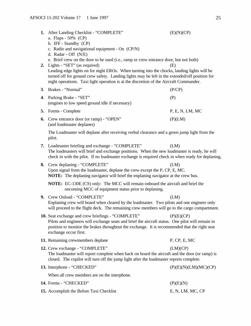
AFSOCI 11-202 Volume 17 1 June 1997 25
1. After Landing Checklist - “COMPLETE” (E)(N)(CP)a. Flaps - 50% (CP)b. IFF - Standby (CP)c. Radio and navigational equipment - On (CP/N)d. Radar - Off (N/E)e. Brief crew on the door to be used (i.e., ramp or crew entrance door, but not both)
2. Lights - “SET” (as required) (E)Leading edge lights on for night EROs. When turning into the chocks, landing lights will beturned off for ground crew safety. Landing lights may be left in the extended/off position fornight operations. Taxi light operation is at the discretion of the Aircraft Commander.
3. Brakes - “Normal” (P/CP)
4. Parking Brake - “SET” (P)(engines to low speed ground idle if necessary)
5. Forms - Complete P, E, N, LM, MC
6. Crew entrance door (or ramp) - “OPEN” (P)(LM)(and loadmaster deplanes)
The Loadmaster will deplane after receiving verbal clearance and a green jump light from thepilot.
7. Loadmaster briefing and exchange - “COMPLETE” (LM)The loadmasters will brief and exchange positions. When the new loadmaster is ready, he willcheck in with the pilot. If no loadmaster exchange is required check in when ready for deplaning.
8. Crew deplaning - “COMPLETE” (LM)Upon signal from the loadmaster, deplane the crew except the P, CP, E, MC.NOTE: The deplaning navigator will brief the enplaning navigator at the crew bus.
NOTE: EC-130E (CS) only: The MCC will remain onboard the aircraft and brief theoncoming MCC of equipment status prior to deplaning.
9. Crew Onload - “COMPLETE” (LM)Enplaning crew will board when cleared by the loadmaster. Two pilots and one engineer onlywill proceed to the flight deck. The remaining crew members will go to the cargo compartment.
10. Seat exchange and crew briefings - “COMPLETE” (P)(E)(CP)Pilots and engineers will exchange seats and brief the aircraft status. One pilot will remain inposition to monitor the brakes throughout the exchange. It is recommended that the right seatexchange occur first.
11. Remaining crewmembers deplane P, CP, E, MC
12. Crew exchange - “COMPLETE” (LM)(CP)The loadmaster will report complete when back on board the aircraft and the door (or ramp) isclosed. The copilot will turn off the jump light after the loadmaster reports complete.
13. Interphone - “CHECKED” (P)(E)(N)(LM)(MC)(CP)
When all crew members are on the interphone.
14. Forms - “CHECKED” (P)(E)(N)
15. Accomplish the Before Taxi Checklist E, N, LM, MC, CP

AFSOCI 11-202 Volume 17 1 June 1997 26
Section D -- Restrictions and Limitations
2.15.1. General.
2.15.1. A navigator is required on all cross country, overwater, tactical training, air refueling missions,and all other flights when thunderstorms, forecast or actual, are in the local area.
2.15.2. The radar will be operational on all flights when thunderstorms are forecast.
2.16. Aircraft Operation Restrictions:
2.16.1. All normal EC-130E(CS) operations are restricted to a maximum airspeed of 250 KIAS.
2.16.2. During aerial refueling missions, fuel will not be onloaded with an inoperative drain pump, orusing auxiliary hydraulic system.
2.16.3. Practice maximum effort takeoffs and landings are prohibited.
2.16.4. Stop and go landings will not be accomplished in the EC-130E(CS) aircraft. If stop and golandings are accomplished in the EC-130E(SH), maximum power will be used for the takeoff.
2.16.5. Except when required by an actual emergency, FCF, or Aircrew Systems Training Sortie syllabus,the paratroop door(s) and/or ramp and door will not be opened in flight.
2.16.6. Except for emergencies, the maximum landing weight in the EC-130E(CS) will not exceed 140,000pounds for “training” sorties. Maximum weight for no flap landings is 120,000 pounds.
2.17. Tactical Altitude Flight Restrictions.
2.17.1. Tactics/low level training flights will be conducted in day VMC only.
2.17.2. Tactics/low level training profiles and/or flight procedures will be flown only on scheduledtactics/low level training flights by tactics/low level qualified crews or crewmembers formally entered in thetactics/low level training program and under the direct supervision of a qualified tactics/low levelinstructor.
2.17.3. (Day VMC only) Tactics/low level qualified pilot and pilots formally entered in the tactics/lowlevel qualification program will maintain a minimum of 500 ft modified contour or as limited by airspacerequirements, whichever is more restrictive. Qualified tactics/low level instructors may demonstrate 300 ftmodified contour.
2.17.4. Instructors: Qualified Tactics/low level IPs or pilots officially in the tactics/low level instructorupgrade program and under the direct supervision of a qualified tactics/low level instructor may fly DayVMC at 300 ft modified contour or as limited by airspace requirements, whichever is more restrictive.
2.17.5. Tactics/low level qualified crews participating in a formal tactics/low level school (example:AATTC, St Joe) with a qualified course instructor are authorized 300 ft modified contour or as limited bycourse or airspace requirements, whichever is more restrictive. 300 ft only applies during theirparticipation in the course.
2.17.6. Commando Solo aircraft will not fly below the ridge line on any tactics/low level training flight onVR704 from Point G to J, VR705 from point D to F, or VR707 from Point F to I.
2.17.7. During all training and exercise missions, defensive maneuvers will never be accomplished usingasymmetric thrust. To defeat a real threat in an actual combat situation, use extreme caution whenperforming defensive maneuvers if asymmetric thrust results from the loss of power in an engine. Undernormal combat conditions do not use asymmetric thrust.

AFSOCI 11-202 Volume 17 1 June 1997 27
2.17.8. Do not fly training or exercise missions at tactical altitudes with an aircraft weight of greater than145,000 lbs. Not applicable to combat or contingency operations.
2.17.9. Tactics qualified pilots and pilots formally entered in the tactics qualification program will use amaximum of 45 degrees of bank angle for practice emergency tactical descent procedures. Qualifiedtactics instructors may demonstrate practice emergency tactical descents using a maximum of 60 degrees ofbank angle.
2.17.10. Terminate practice emergency tactical descent procedures a minimum of 3,000 ft AGL for allCommando Solo aircraft, Senior Scout configured EC-130E aircraft, or Senior Hunter aircraft weighingmore than 110,000 lbs.; and 2,000 ft AGL for Senior Hunter aircraft weighing less than 110,000 lbs.
2.18. National Guard Bureau Restrictions.
2.18.1. The following inflight training restrictions are imposed upon the 193 SOW by the National GuardBureau. They apply to all EC-130E training sorties, or as noted.
2.18.2. Copilot simulated engine out approaches, landings, and go arounds are restricted to the simulator.
2.18.3. Copilots are restricted to landings with crosswinds no higher than the recommended zone duringboth training and operational missions.
2.18.4. Copilots are restricted to the simulator for no flap approaches and landings.
2.18.5. Planned go arounds are not authorized for three engine no flap approaches.
2.18.6. All go arounds directed by a controlling agency will require termination of the simulatedemergency and restoration of flaps and throttles to normal operating positions.
2.18.7. No flap circling approaches will not be compounded with simulated engine out conditions.
2.18.8. Simulated two engine approaches are prohibited.
2.18.9. Practice three engine takeoffs are prohibited.
STEPHEN R. CONNELLY, Col, USAFDirector, Operations
DISTRIBUTION X:HQ USAF/XOOTU, Washington DC 20330-5000 ................... 1USSOCOM/SOJ3, MacDill AFB FL 33608-7001.................... 1

AFSOCI 11-202 Volume 17 1 June 1997 28
THIS PAGE INTENTIONALLY LEFT BLANK

AFSOCI 11-202 Volume 17 1 June 1997 29
ATTACHMENT 1
----------------------------------------------------------------------------------------------|AFSOCI 11-202 Vol 17 Attachment 1 1 May 1997 || ERO ABBREVIATED CHECKLIST || || 1. After Landing Checklist - “COMPLETE” (E)(N)(CP) || (Brief crew on the door/ramp to be used) || || 2. Lights - “SET” (as required) (E) || (Leading edge lights on for night EROs) || || 3. Brakes - “NORMAL” (P/CP) || || 4. Parking brake - “SET” (P) || (engines to low speed ground idle if necessary) || || 5. Forms - Complete P, E, N, || LM, MC || || 6. Crew entrance door (or ramp) - “OPEN” (P)(LM) || (and LM deplanes) || || 7. Loadmaster brief/exchange - “COMPLETE” (LM) || || 8. Crew deplaning - “COMPLETE” (LM) || || 9. Crew Onload - “COMPLETE” (LM) || || 10. Seat exchange “COMPLETE” (P)(E)(CP) || and crew briefings - || || 11. Remaining crewmembers deplane P, CP, E, MC || || 12. Crew exchange - “COMPLETE” (LM)(CP) || || 13. Interphone - “CHECKED” (P)(E)(N) || (LM)(MC)(CP) || || 14. Forms - “CHECKED” (P)(E)(N) || || 15. Accomplish the Before Taxi Checklist E, N, LM, MC, || CP |---------------------------------------------------------------------------------------------
REMOVE THIS PAGE AND INSERT IN ABBREVIATED CHECKLIST.

AFSOCI 11-202 Volume 17 1 June 1997 30
THIS PAGE INTENTIONALLY LEFT BLANK

AFSOCI 11-202 Volume 17 1 June 1997 31
ATTACHMENT 2
-------------------------------------------------------------------------------------------------|AFSOCI 11-202 Vol 17 Attachment 2 1 May 1997 || || || COMBAT ENTRY CHECKLIST: || || 1. Defensive Systems "ON" (N)(CP) || || 2. Altimeter (as required) "SET, state setting" (CP)(P)(N) || || 3. Radar Altimeter (as required) "SET, state altitude" (P)(N) || || 4. IFF "SET" as required (CP) || || 5. Unnecessary Equipment "OFF" as required (P)(CP)(N) || and Emitters || || 6. Lights "SET" as required (P)(CP)(E) || (Interior/Exterior) (N)(LM)(MC) || || 7. Gross Weight "_______lbs." E || (Compute range of maneuvering speeds). || || 8. Survival Equipment - "CHECKED" (P)(CP)(E) || as required (N)(LM)(MC) || || 9. Cockpit Equipment - "SECURED" (P)(CP)(E)(N) || || 10. Cargo Compartment - "SECURED" (LM)(MC) || || 11. Lookouts - "CLEARED P || TO POSITION || || 12. Combat Entry Checklist - "COMPLETE" (P)(E)(N) || (LM)(MC)CP) || || || || || |-------------------------------------------------------------------------------------------------
REMOVE THIS PAGE AND INSERT IN ABBREVIATED CHECKLIST.

AFSOCI 11-202 Volume 17 1 June 1997 32
THIS PAGE INTENTIONALLY LEFT BLANK
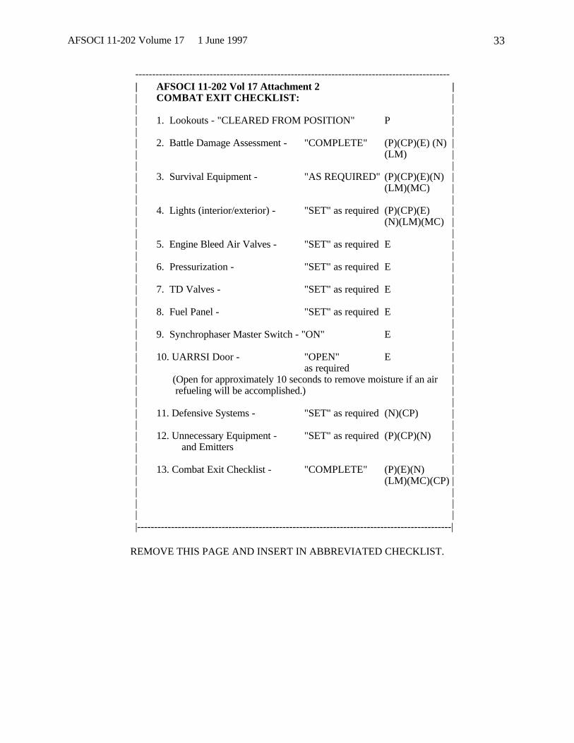
AFSOCI 11-202 Volume 17 1 June 1997 33
---------------------------------------------------------------------------------------------| AFSOCI 11-202 Vol 17 Attachment 2 || COMBAT EXIT CHECKLIST: || || 1. Lookouts - "CLEARED FROM POSITION" P || || 2. Battle Damage Assessment - "COMPLETE" (P)(CP)(E) (N) || (LM) || || 3. Survival Equipment - "AS REQUIRED" (P)(CP)(E)(N) || (LM)(MC) || || 4. Lights (interior/exterior) - "SET" as required (P)(CP)(E) || (N)(LM)(MC) || || 5. Engine Bleed Air Valves - "SET" as required E || || 6. Pressurization - "SET" as required E || || 7. TD Valves - "SET" as required E || || 8. Fuel Panel - "SET" as required E || || 9. Synchrophaser Master Switch - "ON" E || || 10. UARRSI Door - "OPEN" E || as required || (Open for approximately 10 seconds to remove moisture if an air || refueling will be accomplished.) || || 11. Defensive Systems - "SET" as required (N)(CP) || || 12. Unnecessary Equipment - "SET" as required (P)(CP)(N) || and Emitters || || 13. Combat Exit Checklist - "COMPLETE" (P)(E)(N) || (LM)(MC)(CP) || || || ||---------------------------------------------------------------------------------------------|
REMOVE THIS PAGE AND INSERT IN ABBREVIATED CHECKLIST.