by: val tocitu jason kulpe alexandre mariuzza me 4447/6405 october 29 th, 2009
TRANSCRIPT
By: Val Tocitu
Jason KulpeAlexandre Mariuzza
ME 4447/6405October 29th, 2009
10/29/2009Pulse Width Modulation - Val Tocitu, Jason Kulpe, Alex Mariuzza 2
Introduction and definitions Types of PWM Methods of generation Characteristics of PWM Applications and examples Implementation on the HCS12
Presenter: Val Tocitu

What is it?Output signal alternates between on and off within
specified periodControls power received by a deviceThe voltage seen by the load is directly proportional
to the source voltage
10/29/2009Pulse Width Modulation - Val Tocitu, Jason Kulpe, Alex Mariuzza 3

DefinitionsDuty Cycle: on-time / periodVlow is often zero
10/29/2009Pulse Width Modulation - Val Tocitu, Jason Kulpe, Alex Mariuzza 4
LOWHIAVG VDDVV )1(

Types of Pulse WidthPulse center fixed, edges modulatedLeading edge fixed, tailing edge modulatedTailing edge fixed, leading edge modulatedPulse Width constant, period modulated
10/29/2009Pulse Width Modulation - Val Tocitu, Jason Kulpe, Alex Mariuzza 5

Types of Pulse Width
10/29/2009Pulse Width Modulation - Val Tocitu, Jason Kulpe, Alex Mariuzza 6
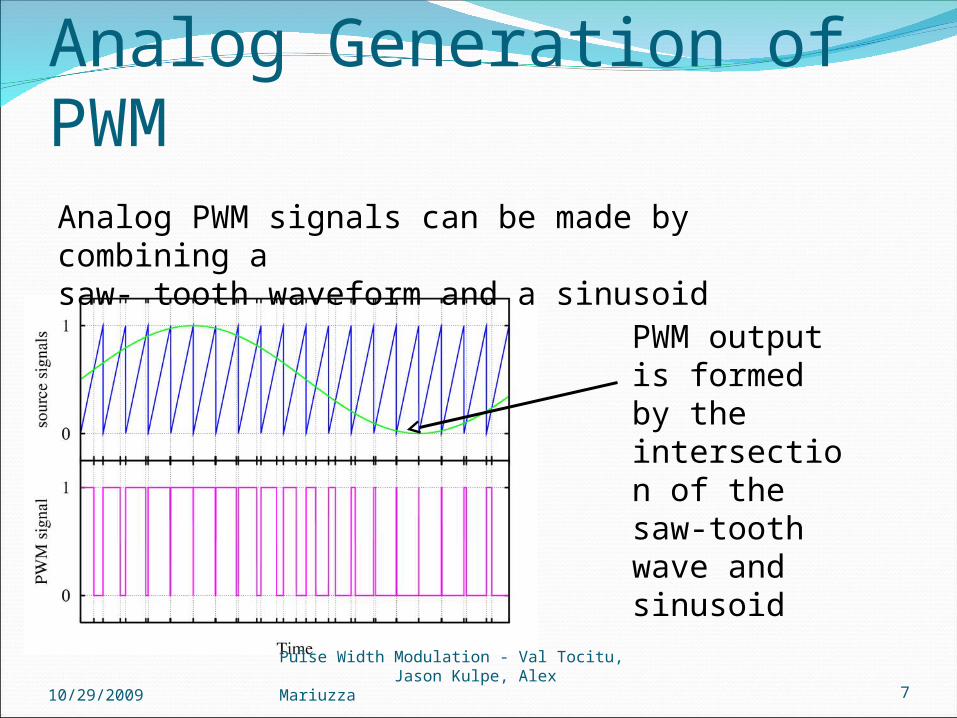
Analog PWM signals can be made by combining a saw- tooth waveform and a sinusoid
10/29/2009Pulse Width Modulation - Val Tocitu, Jason Kulpe, Alex Mariuzza 7
PWM output is formed by the intersection of the saw-tooth wave and sinusoid
Analog Generation of PWM
Digital Methods of Generating PWMDigital: Counter used to handle transitionDelta : used to find the PWM at a certain limitDelta Sigma: used to find the PWM but has advantage of
reducing optimization noise
10/29/2009Pulse Width Modulation - Val Tocitu, Jason Kulpe, Alex Mariuzza 8
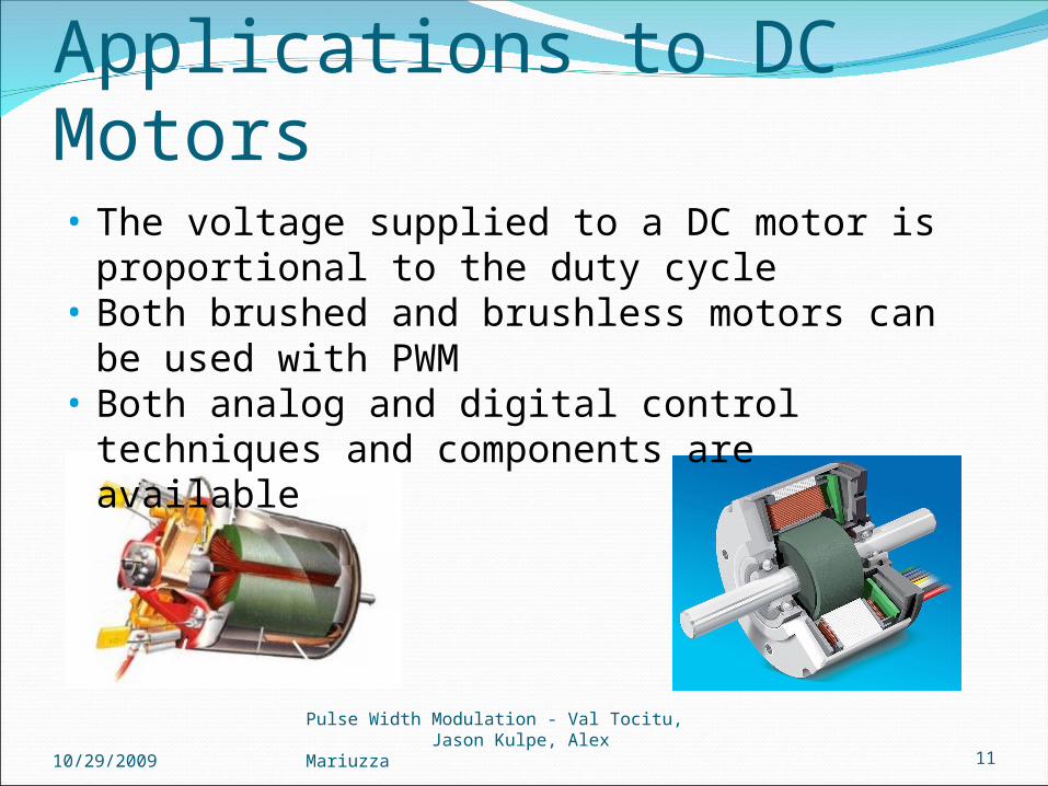
Applications to DC Motors
10/29/2009Pulse Width Modulation - Val Tocitu, Jason Kulpe, Alex Mariuzza 11
• The voltage supplied to a DC motor is proportional to the duty cycle
• Both brushed and brushless motors can be used with PWM
• Both analog and digital control techniques and components are available

Three Phase AC motors with PWM
3 different AC currents at different phasesPhase: 120 degrees apart
Creates constant power transfer
Rotating magnetic fieldPulses substitute for AC
current
10/29/2009Pulse Width Modulation - Val Tocitu, Jason Kulpe, Alex Mariuzza 12

Space Vector ModulationUsed for three-phase AC motorsConvert DC current to AC currentGates turned on/off at different intervals3 PWM created
10/29/2009Pulse Width Modulation - Val Tocitu, Jason Kulpe, Alex Mariuzza 13
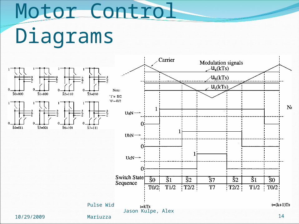
Motor Control Diagrams
10/29/2009Pulse Width Modulation - Val Tocitu, Jason Kulpe, Alex Mariuzza 14
• average value proportional to duty cycle, D• low power used in transistors used to switch
the signal• fast switching possible due to MOSFETS
and power transistors at speeds in excess of 100 kHz
• digital signal is resistant to noise • less heat dissipated versus using resistors
for intermediate voltage values
10/29/2009Pulse Width Modulation - Val Tocitu, Jason Kulpe, Alex Mariuzza 15
Advantages of PWM
10/29/2009Pulse Width Modulation - Val Tocitu, Jason Kulpe, Alex Mariuzza 16
CostComplexity of circuitRadio Frequency InterferenceVoltage spikes Electromagnetic noise
Disadvantages of PWM
10/29/2009Pulse Width Modulation - Val Tocitu, Jason Kulpe, Alex Mariuzza 17
Introduction and definitions Types of PWM Methods of generation Characteristics of PWM Applications and examples Implementation on the HCS12
Presenter: Jason Kulpe
• In the past, motors were controlled at intermediate speed by using resistors to lower delivered power
• Electric stove heater• Lamp dimmers• Voltage regulation – convert 12 volts to 5 volts by
having a 41.7% duty cycle• Sound production: PWM controlled signals give
sound effects similar to a chorus• Power transfer: PWM used to reduce the total
power given to a load without relying on resistive losses
10/29/2009Pulse Width Modulation - Val Tocitu, Jason Kulpe, Alex Mariuzza 18
Applications of PWM

• commonly used in toys• lowpass filter smooths out transients from harmonic effects• frequency values of harmonics doesn’t change, but the
amplitude does, which adjusts the analog output signal
10/29/2009Pulse Width Modulation - Val Tocitu, Jason Kulpe, Alex Mariuzza 19
PWM used with D/A conversion

10/29/2009Pulse Width Modulation - Val Tocitu, Jason Kulpe, Alex Mariuzza 20
• clock signal is found “inside” PWM signal• more resistant to noise effects than binary data alone• effective at data transmission over long distance transmission lines
PWM used to transmit data in telecommunications

1. Must be at least 10 times higher than the control system frequency
2. Higher than 20kHz – audible frequency of sounds to avoid annoying sound disturbances, caused by magnetostriction
3. If too low the motor is pulsed, not continuous, because the motor’s inductance can not maintain the current
4. Inverse of frequency should be much less than the motor/load time constant
5. Higher error from ripple voltages
Frequency of the PWM Signal Upper LimitsLower Limits
1. If too high the inductance of the motor causes the current drawn to be unstable
2. MOSFET transistor generates heat during switching
3. Limited by resolution of controller4. Eddy currents generated in
electromagnetic coils which lead to adverse heating
5. Heat losses in electromagnetic materials is proportional to frequency squared
10/29/2009Pulse Width Modulation - Val Tocitu, Jason Kulpe, Alex Mariuzza 22
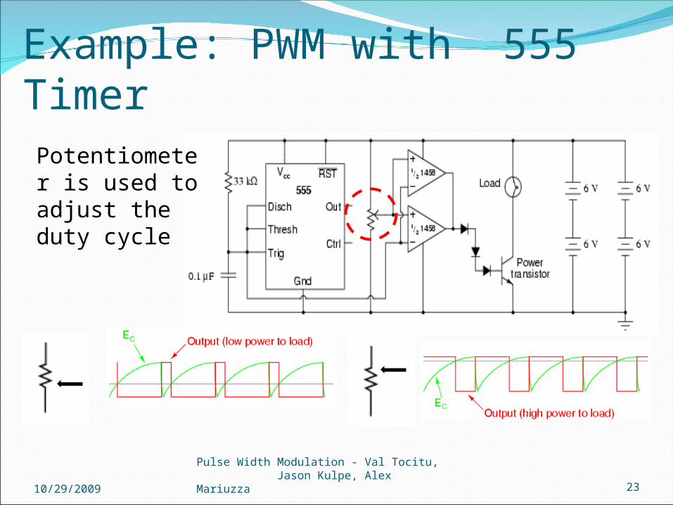
Potentiometer is used to adjust the duty cycle
10/29/2009Pulse Width Modulation - Val Tocitu, Jason Kulpe, Alex Mariuzza 23
Example: PWM with 555 Timer

1. Maxon EC-16 brushless motor, Time constant = 8.75 ms
2. Want to avoid audible frequenciesf ≥ 20 kHz
3. PID control loop running at 150 Hzf ≥ 10 ∙ 150 Hz
Requirements
Hz1175.81
fmsf
10/29/2009Pulse Width Modulation - Val Tocitu, Jason Kulpe, Alex Mariuzza 24
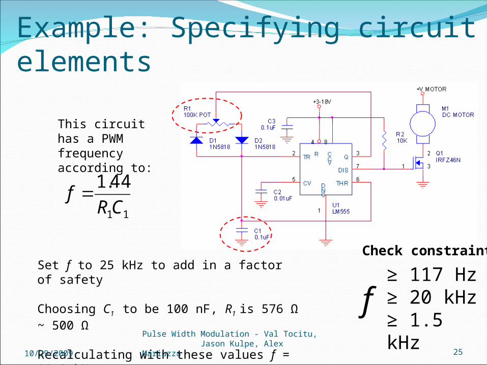
Example: Specifying circuit elements
11
44.1
CRf
Set f to 25 kHz to add in a factor of safety
Choosing C1 to be 100 nF, R1 is 576 Ω ~ 500 Ω
Recalculating with these values f = 28.8 kHz
This circuit has a PWM frequency according to:
≥ 117 Hz≥ 20 kHz≥ 1.5 kHz
f
Check constraints
10/29/2009Pulse Width Modulation - Val Tocitu, Jason Kulpe, Alex Mariuzza 25
Example: Specifying circuit elements
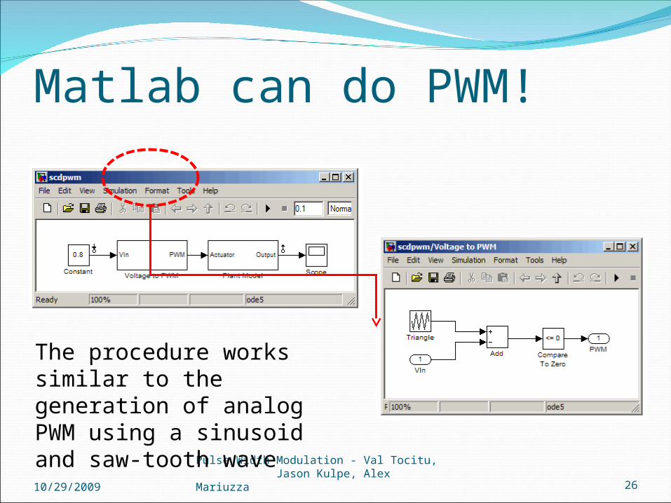
Matlab can do PWM!
10/29/2009Pulse Width Modulation - Val Tocitu, Jason Kulpe, Alex Mariuzza 26
The procedure works similar to the generation of analog PWM using a sinusoid and saw-tooth wave
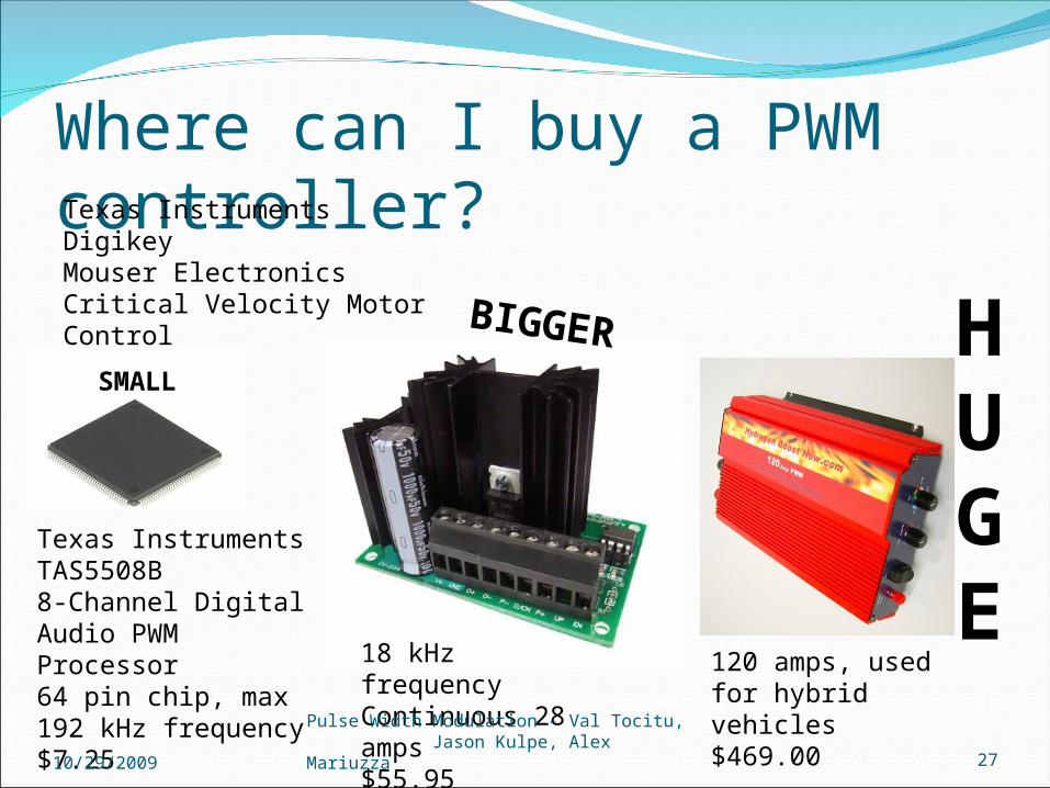
18 kHz frequencyContinuous 28 amps$55.95
Where can I buy a PWM controller?Texas InstrumentsDigikeyMouser ElectronicsCritical Velocity Motor Control
Texas Instruments TAS5508B8-Channel Digital Audio PWM Processor64 pin chip, max 192 kHz frequency$7.25
120 amps, used for hybrid vehicles$469.00
SMALL
BIGGER HUGE
10/29/2009Pulse Width Modulation - Val Tocitu, Jason Kulpe, Alex Mariuzza 27

10/29/2009Pulse Width Modulation - Val Tocitu, Jason Kulpe, Alex Mariuzza 28
Introduction and definitions Types of PWM Methods of generation Characteristics of PWM Applications and examples Implementation on the HCS12
Presenter: Alex Mariuzza

PWM ImplementationThe signal is outputted
through Port PSix ChannelsDedicated Chip
10/29/2009Pulse Width Modulation - Val Tocitu, Jason Kulpe, Alex Mariuzza 29

PWM Module Each channel has a
dedicated counter Programmable duty
and periodIndependently
adjustable clock, polarity, and alignment
10/29/2009Pulse Width Modulation - Val Tocitu, Jason Kulpe, Alex Mariuzza 30
PWM Module- Other Features
8-bit and 16-bit resolution supportedTwo PWM channels can be concatenated together
Four source clocks (A, SA, B, SB)Emergency ShutdownSome changes take a complete cycle to be implemented Modes of Operation:
Normal: everything is availableWait: Low-power consumption and clock disabledFreeze: Option to disable clock is available
10/29/2009Pulse Width Modulation - Val Tocitu, Jason Kulpe, Alex Mariuzza 31
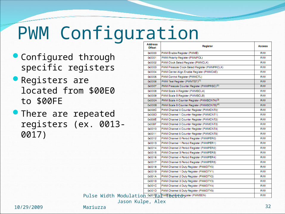
PWM ConfigurationConfigured through
specific registersRegisters are located from
$00E0 to $00FEThere are repeated
registers (ex. 0013-0017)
10/29/2009Pulse Width Modulation - Val Tocitu, Jason Kulpe, Alex Mariuzza 32

PWM Enable Register
Located at $00E0Code Warrior variable: PWMESet PWMEx to 0 to disable the channelSet PWMEx to 1 to enable itChannel is activated when bit is set If 16-bit resolution used, then PWME4/2/0 are deactivated
10/29/2009Pulse Width Modulation - Val Tocitu, Jason Kulpe, Alex Mariuzza 33
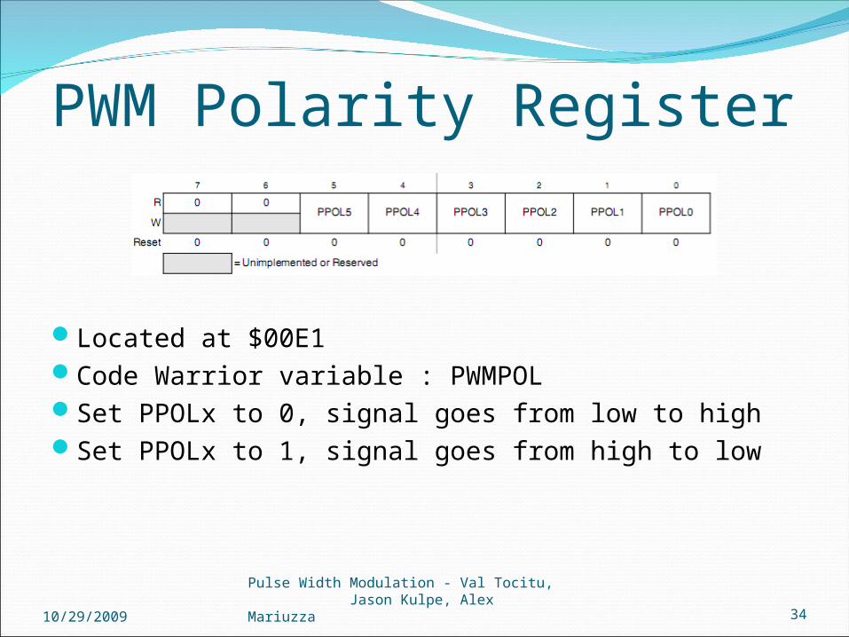
PWM Polarity Register
Located at $00E1Code Warrior variable : PWMPOLSet PPOLx to 0, signal goes from low to highSet PPOLx to 1, signal goes from high to low
10/29/2009Pulse Width Modulation - Val Tocitu, Jason Kulpe, Alex Mariuzza 34
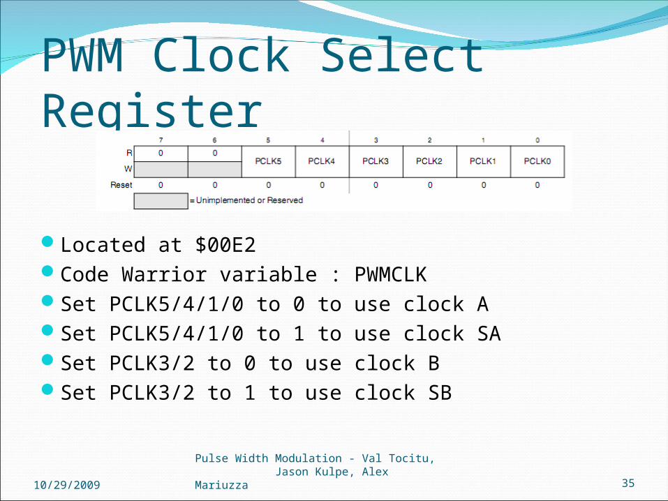
PWM Clock Select Register
Located at $00E2Code Warrior variable : PWMCLKSet PCLK5/4/1/0 to 0 to use clock ASet PCLK5/4/1/0 to 1 to use clock SASet PCLK3/2 to 0 to use clock BSet PCLK3/2 to 1 to use clock SB
10/29/2009Pulse Width Modulation - Val Tocitu, Jason Kulpe, Alex Mariuzza 35
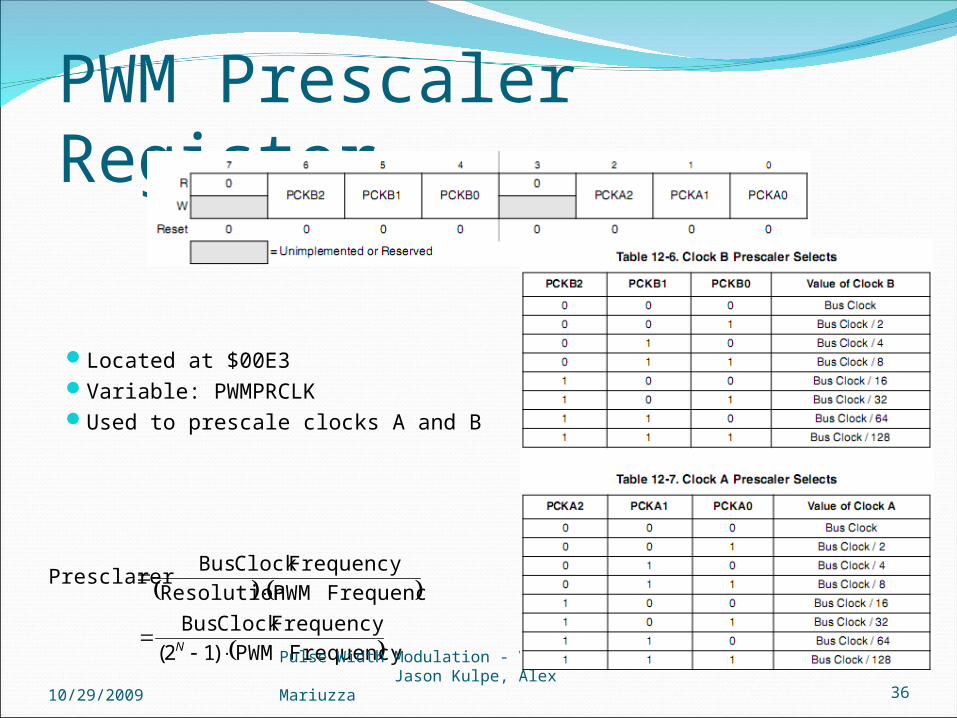
PWM Prescaler Register
Located at $00E3Variable: PWMPRCLKUsed to prescale clocks A and B
Frequency PWM)12(
FrequencyClock Bus
Frequency PWMResolution
FrequencyClock BusPresclarer
N
10/29/2009Pulse Width Modulation - Val Tocitu, Jason Kulpe, Alex Mariuzza 36
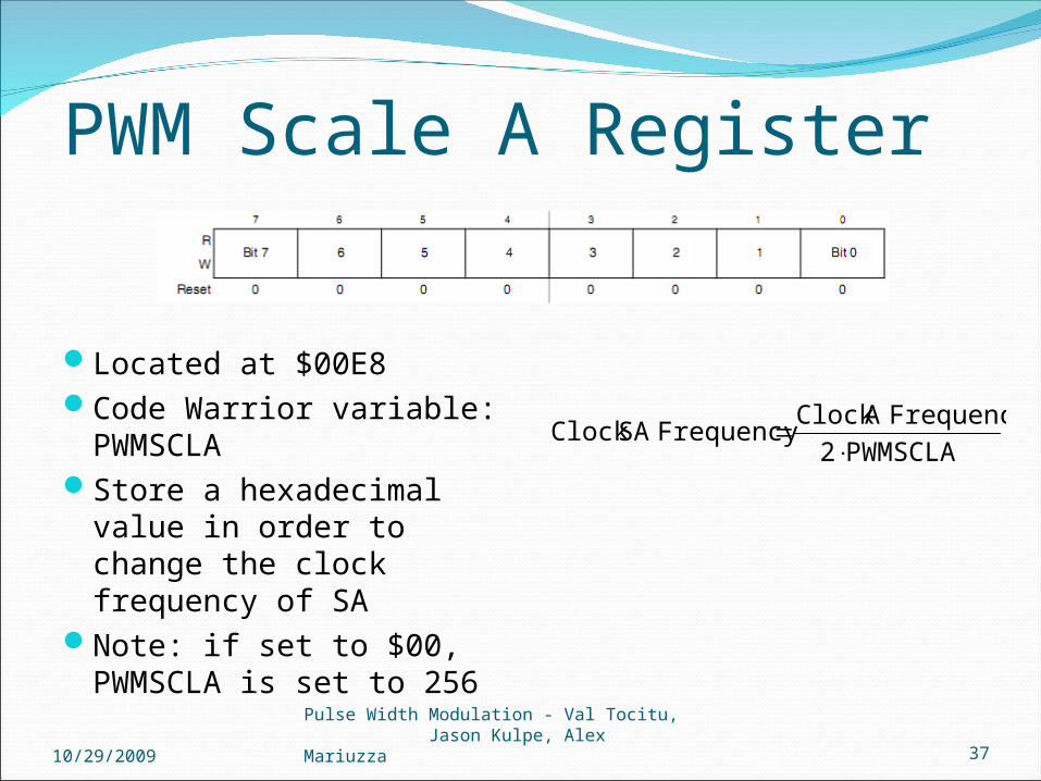
PWM Scale A Register
Located at $00E8Code Warrior variable:
PWMSCLAStore a hexadecimal value
in order to change the clock frequency of SA
Note: if set to $00, PWMSCLA is set to 256
PWMSCLA2
FrequencyA Clock FrequencySA Clock
10/29/2009Pulse Width Modulation - Val Tocitu, Jason Kulpe, Alex Mariuzza 37

PWM Scale B Register
Located at $00E9Code Warrior variable:
PWMSCLBStore a hexadecimal value
in order to change the clock frequency of SA
Note: if set to $00, PWMSCLB is set to 256
PWMSCLB2
Frequency BClock Frequency SBClock
10/29/2009Pulse Width Modulation - Val Tocitu, Jason Kulpe, Alex Mariuzza 38

PWM Center Align Register
Located at $00E4Code Warrior variable: PWMCAESet CAEx to 0 for left align signalSet CAEx to 1 for center align signalNote: can only be set when channel is disabled
10/29/2009Pulse Width Modulation - Val Tocitu, Jason Kulpe, Alex Mariuzza 39
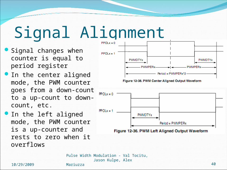
Signal AlignmentSignal changes when counter
is equal to period register In the center aligned mode,
the PWM counter goes from a down-count to a up-count to down-count, etc.
In the left aligned mode, the PWM counter is a up-counter and rests to zero when it overflows
10/29/2009Pulse Width Modulation - Val Tocitu, Jason Kulpe, Alex Mariuzza 40
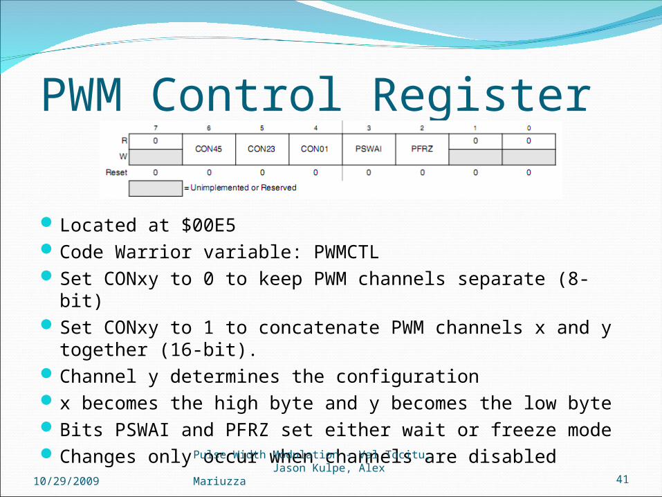
PWM Control Register
Located at $00E5Code Warrior variable: PWMCTLSet CONxy to 0 to keep PWM channels separate (8-bit)Set CONxy to 1 to concatenate PWM channels x and y together (16-
bit).Channel y determines the configurationx becomes the high byte and y becomes the low byteBits PSWAI and PFRZ set either wait or freeze modeChanges only occur when channels are disabled
10/29/2009Pulse Width Modulation - Val Tocitu, Jason Kulpe, Alex Mariuzza 41
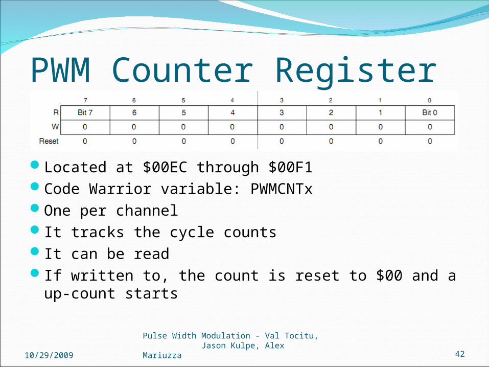
PWM Counter Register
Located at $00EC through $00F1Code Warrior variable: PWMCNTxOne per channelIt tracks the cycle countsIt can be readIf written to, the count is reset to $00 and a up-count starts
10/29/2009Pulse Width Modulation - Val Tocitu, Jason Kulpe, Alex Mariuzza 42
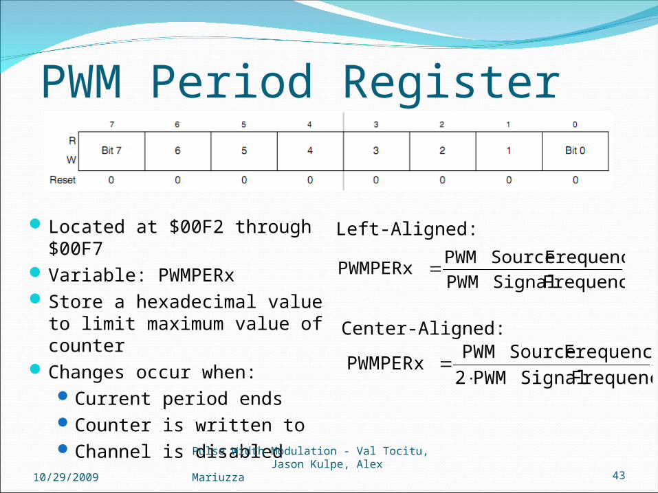
PWM Period Register
Located at $00F2 through $00F7 Variable: PWMPERxStore a hexadecimal value to limit
maximum value of counterChanges occur when:
Current period endsCounter is written toChannel is disabled
Frequency Signal PWM
Frequency Source PWMPWMPERx
Left-Aligned:
Frequency Signal PWM2
Frequency Source PWMPWMPERx
Center-Aligned:
10/29/2009Pulse Width Modulation - Val Tocitu, Jason Kulpe, Alex Mariuzza 43

PWM Duty Register
100
PWMPERxCycleDuty -PWMPERx PWMDTYx
• Located at $00F8 through $00FD• Code Warrior variable: PWMDTYx• Store a hexadecimal value to control when signal changes • Changes occur when:
• Current period ends• Counter written to• Channel is disabled
100
PWMPERx CycleDuty PWMDTYx
Polarity = 0:
10/29/2009 44Polarity = 1:

PWM Shutdown Register
• Located at $00FE
• Code Warrior variable: PWMSDN
• PWMENA: Enables and disables emergency shut down
• PWMIF (Interrupt flag): Set when an input is detected in pin 5
• PWMIE (Interrupt Enable): Enables and disables CPU interrupts
• PWMRSTRT: Resets the counters
• PWMLVL (Shutdown Output Level): Determines if output is high or low when shutdown
• PWM5IN (Input Status): Reflects status of pin 5
• PWM5INL: Determines active level of pin 5 45

How it all worksClock A, SA, B, or SB
10/29/2009Pulse Width Modulation - Val Tocitu, Jason Kulpe, Alex Mariuzza 46
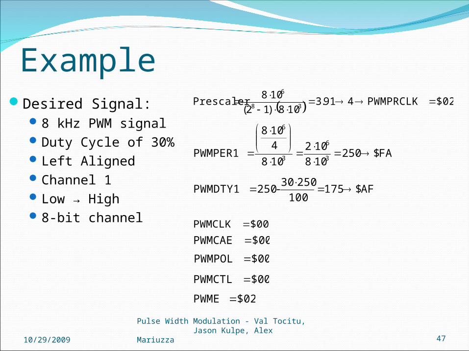
ExampleDesired Signal:
8 kHz PWM signalDuty Cycle of 30%Left AlignedChannel 1Low → High8-bit channel
$02PWMPRCLK491.3108)12(
108Prescaler
38
6
$00PWMCLK
FA$250108
102
108
4108
PWMPER13
6
3
6
AF$175100
25030-250 PWMDTY1
$00PWMCAE
$02PWME
$00PWMPOL
$00PWMCTL
10/29/2009Pulse Width Modulation - Val Tocitu, Jason Kulpe, Alex Mariuzza 47
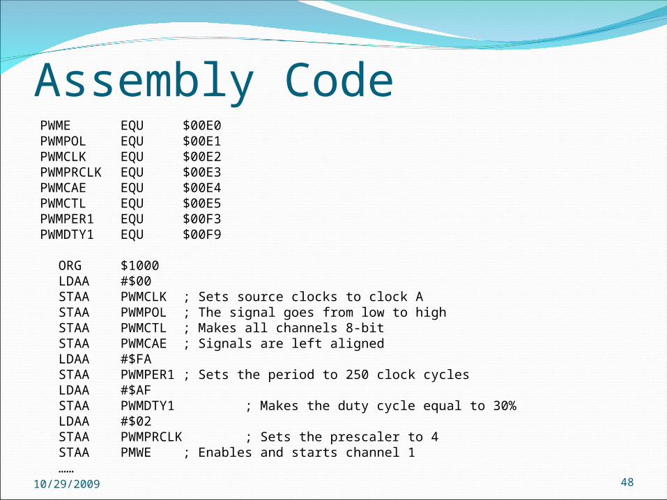
Assembly CodePWME EQU $00E0 PWMPOL EQU $00E1 PWMCLK EQU $00E2 PWMPRCLK EQU $00E3 PWMCAE EQU $00E4 PWMCTL EQU $00E5 PWMPER1 EQU $00F3PWMDTY1 EQU $00F9
ORG $1000LDAA #$00STAA PWMCLK ; Sets source clocks to clock ASTAA PWMPOL ; The signal goes from low to highSTAA PWMCTL ; Makes all channels 8-bitSTAA PWMCAE ; Signals are left alignedLDAA #$FASTAA PWMPER1 ; Sets the period to 250 clock cycles LDAA #$AFSTAA PWMDTY1 ; Makes the duty cycle equal to 30%LDAA #$02STAA PWMPRCLK ; Sets the prescaler to 4STAA PMWE ; Enables and starts channel 1……10/29/2009 48
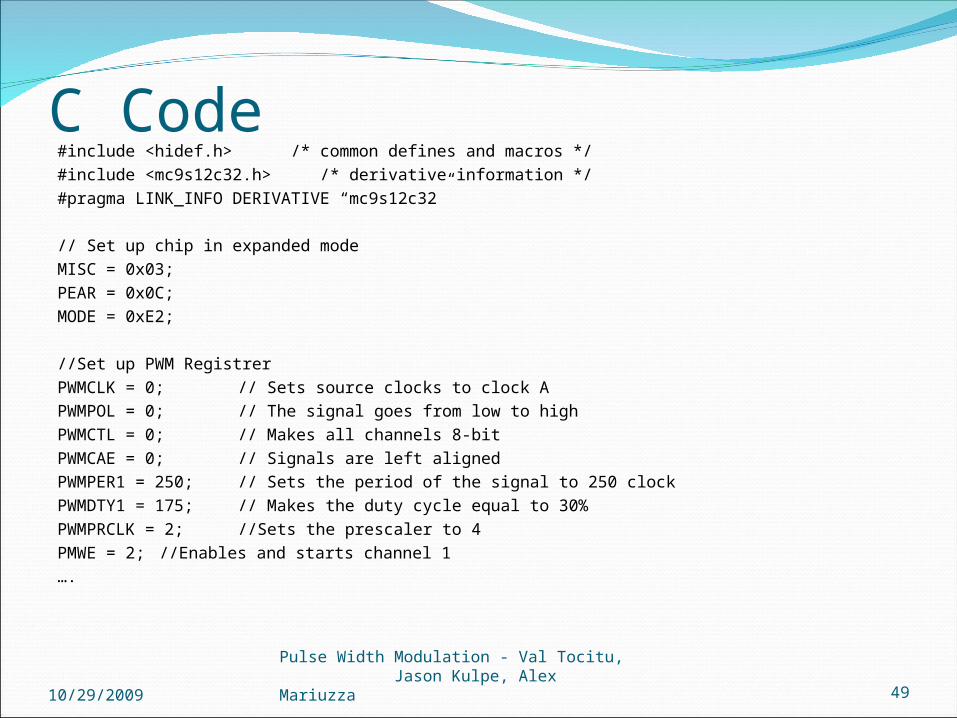
C Code#include <hidef.h> /* common defines and macros */
#include <mc9s12c32.h> /* derivative information */
#pragma LINK_INFO DERIVATIVE “mc9s12c32”
// Set up chip in expanded mode
MISC = 0x03;
PEAR = 0x0C;
MODE = 0xE2;
//Set up PWM Registrer
PWMCLK = 0; // Sets source clocks to clock A
PWMPOL = 0; // The signal goes from low to high
PWMCTL = 0; // Makes all channels 8-bit
PWMCAE = 0; // Signals are left aligned
PWMPER1 = 250; // Sets the period of the signal to 250 clock
PWMDTY1 = 175; // Makes the duty cycle equal to 30%
PWMPRCLK = 2; //Sets the prescaler to 4
PMWE = 2; //Enables and starts channel 1
….
10/29/2009Pulse Width Modulation - Val Tocitu, Jason Kulpe, Alex Mariuzza 49
http://en.wikipedia.org/wiki/Pulse-width_modulationhttp://www.netrino.com/Embedded-Systems/How-To/PWM-Pulse-Width-ModulationCetinkunt, Sabri. Mechatronics. Hoboken, NJ: Wiley, 2006. Print.http://www.jimfranklin.info/microchipdatasheets/00538c.pdfhttp://www.allaboutcircuits.com/vol_6/chpt_6/9.htmlhttp://www.dprg.org/tutorials/2005-11a/index.htmlhttp://www.4qdtec.com/pwm-01.htmlhttp://skywalker.cochise.edu/rgill/ch02elec.ppthttp://pcbheaven.com/wikipages/PWM_Modulation/Matlab 2009 online documentationhttp://www.epanorama.net/links/motorcontrol.html#acMC9S12C Family, MC9S12GC Family Reference Manual, (pp. 347-382)
REFERENCES
10/29/2009Pulse Width Modulation - Val Tocitu, Jason Kulpe, Alex Mariuzza 50

Questions?
10/29/2009Pulse Width Modulation - Val Tocitu, Jason Kulpe, Alex Mariuzza 51