bypass and collection system for protection of …spo.nmfs.noaa.gov/mfr372/mfr3727.pdfturbine...
TRANSCRIPT
MFR PAPER 1125
Bypass and Collection System for Protection of Juvenile Salmon and Trout at Little Goose Dam
JIM ROSS SMITH and WINSTON E. FARR
ABSTRACT -Juvenile fish screening, bypass, and collection facilities at Little Goose Dam on the lower Snake River are described. The complex includes traveling screens for diversion of downstream migrants from turbine intakes, a bypass system for routing fish around the turbines, and a fish collection area for grading, enumeration , and examination of the migrants passed to the tailrace area. The system was operated and evaluated in 1971-72 by the National Marine Fisheries Service under contract to the U.S. Army Corps of Engineers.
INTRODUCTION
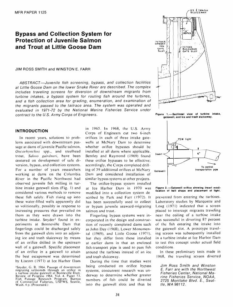
I n recent years, solutions to problems associated with downstream passage at dams of juvenile Pacific salmon , Oncorhynchus spp., and steel head trout, S(/Ill/o gairdneri, have been centered on development of safe diversion, bypass, and collection systems. For a number of years researchers working at dams on the Columbia River in the Pacific Northwest had observed juvenile fish milling in turbine intake gatewell slots (Fig. I) and considered various methods to remove these fish safely. Fish rising up into these water-filled wells apparently did so volitionally, possibly in response to increasing pressures that prevailed on them as they were drawn into the turbine intake. Snyder' found in experiments at Bonneville Dam that fingerlings could be discharged safely from the gateweJl slots into an adjoining ice and trash sluiceway by means of an orifice drilled in the upstream wall of a gatewell. Specific placement of an orifice in a gatewell to attain (he best escapement was determined by Liscom (1971) at Ice Harbor Dam
'Snyder, G. R. 1964. Passage of downstream migrating sa lmonids through an orifice in a turbine intake gatewell a t Bonneville D am. Review of Progress 1964, Vol. 4 , Paper 53. Fish Passage Research Program , Bureau of Commerci al Fisheries, USFWS, Seattle, Wash . 4 p. (Processed.)
in 1965 . In 1968, the U .S. Army Corps of Engineers cut two 6-inch orifices in each of three intake gatewells at McNary Dam to determine whether orifice bypasses should be installed at all dams where applicable. Bentley and Raymond (1969) found these orifice bypasses to be effective; accordingly, the Corps completed drilling of 39 additional orifices at McNary Dam and considered installation of similar bypass systems at other projects .
The orifice-bypass system installed at Ice Harbor Dam in 1970' was modified into a collection system descri bed by Park and F arr (1972). It has been successfully used to collect or bypass juvenile seaward -migrating salmon and trout.
Fingerling bypass systems were incorporated in the design and construction of recently completed dams such asJohn Day (1968), Lower Monumental (1969), and Little Goose (197 I) , but they differ from those installed at earlier dams in that an enclosed fish-transport pipe is used to pass fish around the turbines instead of an ice and trash sluiceway .
During the time that studies were being conducted on orifice bypass systems , concurrent research was underway to determine whether greater numbers of fish could be diverted into the gatewell slots and thus be
31
IN"""f,. . opeQAT- '
I~u I
","TE ~\..o,
,C~ ~ H~A.5'" 5lUICEWAV
lNlA.\(E. , eUL'o·'t.AD , G.A'f~ ~l.OT
Figure 1.-SeclioMI view 01 lurblne inlake, galewell, and Ice and Iraeh Iluiceway.
Gale.oll
To central transportation pipe
Figure 2. -Galewell orifice showing Inlerl modi· fication of bell Ihape and placemenl of light.
prevented from entering the turbines. Laboratory studies by Marquette and Long (1971) indicated that a screen placed to intercept migrants traveling near the ceiling of a turbine intake was successful in diverting 87 percent of the fish entering the intake into the gatewell slot. A prototype travel ing screen was subsequently installed in a turbine intake at Ice Harbor Dam to test this concept under actual field conditions.
In these preliminary tests made in 1968, the traveling screen diverted
Jim Ross Smith and Winston E. Farr are with the Northwest Fisheries Center, National Marine Fisheries Service, NOAA, 2725 Mont/ake Blvd . E., Seattle, WA 98112.

Figure 3.- Fish bypass transport pipe (dark arrow) and racaways lor holding JUVenile salmon and steelhead trout at Little Goose Dam. Transport pipe discharges through upwell at tell end 01 fish holding area (light arrow).
about 75 percent of the juvenile chinook salmon , O. /.~/IlIWYlscl/(/, and 25 percent of the juvenile steel head trout from the turbine intake into a gatewell slol. Further mechanical improvements were made, and three experimental traveling screens were pl aced in operation at Lillie Goose Dam in 1971 to determine the feasibility of utilizing a complete diversion and bypass system for either collection and transport or diversion and bypass to the tailrace of a major portion of the fish entering operating turbine units.
This report describes the system installed and tested at Little Goose Dam in 1971-72. The study was part of a continuing cooperative effort between the National Marine Fisheries Service (N M FS) and the U.S. Army Corps of Engineers to improve fish passage on the Columbia and Snake Rivers.
GATEWELL ORIFICES AND TRANSPORTATION PIPE
Passage of fish from a gatewell slot at Lillie Goose Dam was provided through a submerged orifice. The
Figure 4.- Traveling screen assembly. Screen is ahown extended and in the operating position. Arrow deslgnatas direction 01 travel.
32

1
NOf" ...... ol Fbot [I. G.,e.o
fl. ~75.00
fl. '1Qcr,lZ
Figure 5.-Sectional view of turbine intake unit at Llltle Goole Dam showing traveling screen, barrier screen, support structure, gatewell orifice, and fish transportation pipe.
original orifice was bell-shaped, measuring 14 inches in diameter at the inlet and tapering to 6 inches at its connection with the short section of pipe leading to the main transportation pipe. The latter passageway was 1.0 ft in diameter at the southern end of the powerhouse, enlarging to 3.0 ft at the northern (downstream) end . Each orifice was located in the northeast corner of the gatewell , 20.5 ft below the intake deck and submerged from I to 7 ft, depending upon forebay elevation. Because the quantity of water discharged from the main transportation pipe was controlled , intake velocity at the orifices changed very little. I nitial observations indicated that the unlighted, bell-mouthed opening was relatively ineffective in attracting available fish from the gate-
well. On the other hand, previous tests at McNary and Ice Harbor Dams had indicated that a naturallylighted , straight 6-inch diameter opening was far more effective . Therefore, the orifices at Little Goose Dam were modi fied to provide 6-inch diameter lighted orifices (Fig. 2) .
Water and fish passing through the individual orifices entered the central transportation pipe and were discharged into the tailrace in the area between skeleton turbine unit number 6 and the first spillway bay. Subsequently, the bypass was extended from the original point of discharge by adding approximately 900 ft of 24-inch pipe across the face of the tailrace deck and downstream to fishholding raceways located on the south shore below the dam (Fig. 3) . Fourteen
33
tapered baffles were placed in the interior of this extension to maintain water velocity at 9 fps near the downstream extremity . Each baffle restricted flows to a 15-inch diameter orifice; calculated velocity through these orifices was 23 fps. The system was designed to deliver 28 cfs of water at all times regardless of forebay level. This flow passed into a 5-ft diameter upwell pipe through a water elimination system and discharged the fish into a fish grader located at the fishholding area .
FISH SCREENING FACILITIES
Typical Kaplan turbine units at dams on the Columbia and Snake Rivers have three separate intakes ; hence, three individual screens are required to divert fish from each turbine unit. The first experimental traveling screen (Fig. 4) installed at Ice Harbor Dam was modified to fit slot dimensions at Little Goose Dam. Two additional traveling screens were constructed and installed at the latter site in the spring of 197 I to divert fish entering one of the three operating turbines.
Components of the traveling screen assembly included a rotating belt screen (20.75 X 22.0 X 1.5 ft) , an outer framework for housing the belt screen and drive mechanism, and a support structure (23 X 30 X 3.66 ft) upon which the screen was positioned when operating in the turbine intake. The traveling screen unit was bolted to , and rested on , the support structure. Screen belting consisted of four woven panels of E42 X 36 X 16 wire. Power for rotating the screen at 0 .5 fps was supplied by two hydraulic motors connected to gear boxes with a 7: I reduction . One gear box and motor were attached to each end of the top shaft of the screen. Direction of screen travel was upward on the upstream face and downward on the returning side (Fig. 4).
Installation of the traveling screen assembly was as follows: The turbine was shut down and the bottom support structure was partially lowered into a gatewell and dogged off. The collapsed traveling screen unit was then lifted with the gantry crane, lowered onto the support structure and the

111/11111111111111
Figure 6.-0verhead view 01 11th grader. Shown are Ihe perforaled plale, grader bars, and sprinkler syslem.
two sections were bolted together. After removal of the dogs. the total assembly was then lowered into the intake by use of cable pendants. When the support structure reached the bottom of the turbine intake. the cable pendants were dogged off. The traveling screen was then tilted into operating position at approximately 45 ° by activation of the hydraulic pistons. After the traveling screen had been placed in position. the valve controlling the movement of the traveling screen conveyor belts was activated. and the system was ready to divert fish (Fig. 5).
Separate 25-hp hyd raulic power units were used for each traveling screen. These units were located on the deck adjacent to the gatewell
Figure 7.-Seclional view of separalor showing upwell pipe. perforaled plale, fish grader, and debris ellmlnalor.
l:
opening. Installation and removal of the hoses were expedited with quickdisconnect couplings. Hoses between the top of the traveling screen frame and the intake deck were of the same length as the cable pcndants so they could be installed and removed simultaneously. A more detailed description of the design and operational features of the turbine intake traveling screen is given by Farr (In press).
Fish diverted into the bulkhead gate slot were confined to that area by a vertical barrier screen which prevented movement into other areas of the gatewell (Fig. 5). Prior to the addition of this screen. fish entering the gatewell could pass downstream around the lower beam and back into the turbine intake. Three barrier screens were required for each turbine intake. These were installed in guides fastened to the gatewell walls. Each screen was 21 ft wide by 84 ft deep. Subsequently . portions of these screens (upper and lower ends) were covered with paneling to control Aow turbulence at surface levels in the gatewells. Before installation of the panels. a pronounced upwelling was evident in the gatewells and was believed to ha ve had an adverse effect on egress of fish to the bypass pipe. This surface turbulence was largely eliminated when the panels were installed.
UPWELL AND FISH GRADER
Fish emerging from the upwell at the terminus of the transportation pipe spilled over a perforated-plate screen and then on to the fish grader (Fig. 6). The Aow of water to the fish
r ,- -
Coun{in~ Tunnel
34
grader was regulated by porositycontrol gates beneath the perforatedplate screen (Fig. 7) . Water passing through the screen could be diverted to the holding racew ays or returned directly to the river. The fish grader consisted of aluminum tubes 1.25-inches in diameter and 10ft in length which were progressively spaced from narrow to wide openings to grade fish into three size categories. Spacing could be varied to accommodate the various sizes of fish. Graded fish fell into one of three water-filled hoppers located below the bars. Fish leaving these hoppers passed through a pipe containing an electronic counter an d into one of the five holding raceways.
The grading system functioned satisfactorily . but small debris periodically passed into t he raceways and occasionally plugged the fish transfer pump used to lift fish from the raceways to the marking facility. In the fall of 1972 a traveling debris carrier belt (Fig. 7) was placed between the grading bars and the hoppers . This belt consisted of S/16-i nch cross rods spaced 2 inches on centers with the ends of the rods passing through holes punched in the side bars of C2080 chains. These rods were covered with O.S-inch schedule 80 PYC pipe. leaving a gap of 1.5 inches between the individual cross rods. A preliminary test showed that fish were separated from debris and t hat about 90 percent of the debris was re moved from the system.
When desirable. fish emerging from the upwell could be bypassed directly to the river by merely covering the grader bars with a metal sheet. Fish

Figure B.-Floh crowder with .Ingle screen In po. it Ion in raceway on extreme right. FI.hmarking facility I. in background.
passed in this manner entered a pipe at the end of the grader and were discharged into the front roll of the turbine discharge.
FISH HOLDING AREA
The fish-holding area consisted of five adjacent raceways 80 ft long X 4 ft wide X 7 ft deep . Each raceway was provided with an inlet and outlet screen which prevented escapement of fish . Water flow and depth in each raceway were controlled by adjustment of stoplogs at the head and end of the raceways ; excess water spilled back into the Snake River. Cooling water could be provided when needed by three 30-ton chillers plumbed into the raceways.
When fi sh were removed from the holding area for transfer to the marking building or to fish-transport trucks, each raceway was handled independently. Water depth in a designated raceway was lowered to 2 ft by lifting
stoplogs at the downstream end. The outlet screen was then pulled and fish were crowded toward the intake of the fish pump.
The crowder (Fig . 8) ran on tracks mounted on the two outside walls of the fish-holding area and was powered by a variable-speed , reversible electric motor with reduction gear. A single crowder screen was connected to a traversing hoist to permit ready transfer to any raceway . To remove fish from a raceway, the crowder tramway was moved to the inlet screen and the crowder screen lowered into position. The outlet screen of the raceway was then removed, a slide-gate valve to the pumpintake pipe was opened. and the fish pump was aClivated. The crowder was then moved down toward the exit to concentrate all fish near the pump intake. From this point the fish were either pumped into the marking facility or directly to a transport truck.
The transfer pump was a 5-inch. helical port-impeller type. driven by
a 7.5 hp variable-speed motor . Diameter of the pump inl a ke was 6 inches. During initi a l tests in 1971. before the installation of the debris eliminator. periodic inspection revealed that sticks (8-inch or longer) occasionally lodged a t the junction of the intake pipe and the helical impeller; this condition caused some descaling and injury of fish. A clear plastic section of pipe was installed at this junction to permit ready detection of debris. Where noted, the debris could be immediately removed by unbolting the intake pipe. Total dynamic head (TDH) of the pump comprised 6 ft of suction lift and 12 ft of discharge head .
SUMMATION
In general, the fish diversion. bypass, and collection system at Little Goose Dam operated satisfactori Iy in 1971-72 . More recent inspections in 1973 indicated that incidence of descaling and general physica l condition of the fish were directly associated with turbine load and related approach velocities on the intake traveling screens. Further improvements and modifications to the system are planned and will be tested in forthcoming years.
LITERATURE CITED Bentley. W. W .. and H. L. Raymond. 1969.
Passage of juvenile fish through orifices in gatewells of turbine intakes a t McNary Dam. Tra ns. Am. Fish. Soc. 98: 723-727.
Farr. W. E. In press. Traveling screens for turbine intakes of hydroelectric dams. In Proceedings of Entrainment and Intake Screening Workshop, 5-9 February 1973. The Johns Hopkins Univ ., Baltimore.
Liscom, K. 197 1. Orifice placement in gatewells of lurbine intakes for bypassing juvenile fish a round dams. Trans. Am. Fish. Soc. 100 :319-324.
Marquette, W. M., and C. W. Long . 1971. Laboratory studies of screens for diverting juvenile sa lmon and trout from turbine intakes. Trans. Am. Fish . Soc . 100:439-447.
Park, D. L. . and W. E. Farr. 1972. Collection of juvenile salmon and stee lhead trout passing through orifices in gatewells of turbine intakes at Ice H arbor Dam. Trans. Am. Fish. Soc. 101 :38 1-384.
MFR Paper 1125. From Marine Fisheries Review, Vol. 37, No.2, February 1975. Copies of this paper, in limited numbers, are available from 083, Technical Information Division, Environmental Science Information Center, NOAA, Was hin9ton, DC 20235.
35