bypass level indicator with magnetic roller display model bna · 2014-01-11 · bypass level...
TRANSCRIPT

Bypass level indicatorwith magnetic roller displayModel BNA
Bypass level indicator, model BNA with option level sensor and magnetic switch
Applications
■ Continuous level measurement with visual display of the filling level, without power supply.
■ Volume- or depth-proportional display of the filling level ■ Individual design and corrosion resistant materials enable
a wide spectrum of application ■ Chemical industry, petrochemical industry, natural gas,
offshore, shipbuilding, machine building, power generating equipment, power stations
■ Process water and drinking water treatment, food and beverage industry, pharmaceutical industry
Special features
■ Process- and system-specific solutions possible ■ Operating limits:
- Operating temperature: T = -160 ... +450 °C - Working pressure: P = Vacuum to 420 bar - Limit S. G.: ρ ≥ 400 kg/m3
■ Wide variety of different process connections and materials
■ Level sensor or magnetic switch mounted externally (option)
■ Explosion-protected version (optional)
DescriptionThe WIKA model BNA bypass level indicator consists of a bypass chamber, which, as a communicating interface, is connected laterally to a vessel via 2 process connections (flanged, threaded or welded). Through this type of arrangement, the level in the bypass chamber corresponds to the level in the vessel. The cylindrical float (with a permanent magnet system, mounted within the bypass chamber) transmits the liquid level, contact free, to the outside via the magnetic roller display mounted on the bypass chamber. In this are fitted, at 10 mm intervals, red/white plastic or ceramic rollers with bar magnets.
Through the directional magnetic field of the permanent magnet system in the cylindrical float, the magnetic rollers, through the wall of the bypass chamber, are turned through 180°. For an increasing level from white to red; for a falling level from red to white.Thus the bypass level indicator displays the level of a vessel without a power supply - visible as a red column.
Level measurement
WIKA data sheet LM 10.01
Page 1 of 24WIKA data sheet LM 10.01 ∙ 09/2010

Page 2 of 24 WIKA data sheet LM 10.01 ∙ 09/2010
Further special features
■ Simple, robust and solid design, long service life ■ Bypass chamber made of stainless steel 1.4571 ■ Pressure- and gas-tight separation between measuring
and display chamber ■ Measuring and indicating of the level of aggressive,
combustible, toxic, hot, agitated and contaminated media ■ Without power supply the functioning of the magnetic
roller display is guaranteed even in the case of power failures
■ Available for applications in all areas of industry through use of highly corrosion-resistant materials
■ Continuous measurement of the liquid levels irrespective of physical or chemical changes of state of the measured media, such as: foaming, conductivity, dielectric constant, pressure, vacuum, temperature, vapour, condensation, blistering, effects of boiling
■ Volume-proportional or depth-proportional display of the filling level
■ Interface layer measurement and overall level from ∆-density of more than 50 kg/m3
Options
■ Explosion-protected versions ■ Customer-specific solutions ■ Bypass chamber and float made of different materials ■ Magnetic switch or level sensor mounted externally ■ Bypass chamber end
Illustration of the principle
Design and operating principle
■ In a communicating bypass chamber mounted to the side of a vessel a float moves with the liquid level of the medium to be measured.
■ The radial-symmetric magnetic system, which is positi-oned to immersion height inside the float, simultaneously activates the magnetic roller display, which is fixed to the outside of the bypass chamber, and the switching and measuring elements through its magnetic field.
Terminal box(only with option magnetic switch or level sensor)
Magnetic roller display
Cylindrical float (Z)(with magnetic system)
Bypass chamber
Example
Bypass chamber Magnetic roller
display
Cylindrical float
Magnetic system
Magnetic switch
Level sensors
Illustration with option magnetic switch and level sensor
Mounted bypass level indicator, model BNA

Page 3 of 24WIKA data sheet LM 10.01 ∙ 09/2010
~25
90
X
M...
U...
SpecificationsBypass chamber Ø 42 x 2 mm
Chamber end top Flat top
Options: (see page 24) Vent plug G 1/2" Vent valve Vent flange
Chamber end bottom Flange connection
with drain plug G 1/2" Options: (see page 24) - Drain valve - Drain flange
Process connections Side-side (options see page 23) Flanges DN 10 - DN 25, PN 6, DIN 2631 DN 10 - DN 25, PN 16, DIN 2633 DN 10 - DN 25, PN 40, DIN 2635 DN 32 - DN 100, DIN 2527 1/2" - 4", ANSI B 16.5 class 150 or class 300 Thread or weld stubs GM /... = female thread / size GN /... = male thread / size S /... = weld stubs / Ø
Centre-to-centre distance
Min. 150 mm to max. 2000 mm
Nominal pressure Max. 16 bar (according to float design)
Temperature range Max. 150 °C (according to float design)
Float Model ZTS - Material titanium 3.7035 - S.G. min. 800 kg/m3
- Pressure max. 16 bar - Temperature max. 150 °C Model ZBS - Material Buna - S.G. min. 800 kg/m3
- Pressure max. 6 bar - Temperature max. 80 °C
Magnetic roller display Model MRA For specifications and further designs and options see page 16
Further options: Magnetic switch Level sensor
See page 17 ... 20 See page 21 and 22
Mini bypass level indicatorBypass chamber made of stainless steel 1.4571
M = centre-to-centre distance of the process connections
U = dependent on floatX = according to process connection
Float Model ZBS (material Buna) Model ZTS (material titanium)
Magnetic system
Magnetic system
5050
Dim
ensi
ons
depe
ndin
g on
S.G
.
Dim
ensi
ons
depe
ndin
g on
S.G
.

Page 4 of 24 WIKA data sheet LM 10.01 ∙ 09/2010
90
X
~35
M...
U
SpecificationsBypass chamber Ø 60.3 x 2 mm or Ø 64 x 2 mm
Chamber end top Flat top, welding cap or flange connection
Options: (see page 24) Vent plug G 1/2" Vent valve Vent flange
Chamber end bottom Flange connection
with drain plug G 1/2" Options: (see page 24) - Drain valve - Drain flange
Process connections Side-side (options see page 23) Flanges DN 10 - DN 25, PN 6, DIN 2631 DN 10 - DN 25, PN 16, DIN 2633 DN 10 - DN 25, PN 40, DIN 2635 DN 32 - DN 100, DIN 2527 1/2" - 4", ANSI B 16.5 class 150 or class 300 Thread or weld stubs GM /... = female thread / size GN /... = male thread / size S /... = weld stubs / Ø
Centre-to-centre distance Min. 150 mm to max. 6000 mm (larger distances on request)
Nominal pressure Max. 40 bar (according to flange design)
Temperature range -196 °C ... +450 °C
Temperature classMax. process temperature
T1 T2 T3 T4 T5 T6320 °C 240 °C 160 °C 108 °C 80 °C 68 °C
Float Model ZTSS / ZVSS - P ≤ 25 bar (titanium 3.7035, stainless steel
1.4571) - Float length depending on S.G. - Specifications (see page 14)Model ZTS / ZVS - Float design according to process parameters
S.G., pressure and temperature (see page 15)Magnetic roller display Model MRA: < 200 °C
Model MRK: > 200 °C For specifications and further designs and op-tions see page 16
Further options: Magnetic switch Level sensorElectrical trace heating Bypass chamber insulation
See page 17 ... 20See page 21 and 22
On request
On request
Version PN 6 - PN 40Bypass chamber made of stainless steel 1.4571Option: Explosion-protected version
M = centre-to-centre distance of the process connections
U = dependent on floatX = according to process connection

Page 5 of 24WIKA data sheet LM 10.01 ∙ 09/2010
SpecificationsBypass chamber PN 64: Ø 60.3 x 2 mm or Ø 60.3 x 2.6 mm
PN 100: Ø 65 x 3.5 mmChamber end top Flat top, welding cap or flange connection
DN 50, PN 64 or ANSI 2", class 600 DN 50, PN 100 or ANSI 2", class 600Options: (see page 24) Vent plug G 1/2" Vent valve Vent flange
Chamber end bottom Flange connection
DN 50, PN 64 or ANSI 2", class 600 DN 50, PN 100 or ANSI 2", class 600with drain plug G 1/2“ Options: (see page 24) - Drain valve - Drain flange
Process connections Side-side (options see page 23) Flanges DN 10 - DN 25, PN 64, DIN 2637 DN 10 - DN 25, PN 100, DIN 2637 1/2" - 3", ANSI B 16.5, class 600 Thread or weld stubs GM /... = female thread / size GN /... = male thread / size S /... = weld stubs / Ø
Centre-to-centre distance Min. 150 mm to max. 6000 mm (larger distances on request)
Nominal pressure PN 64: max. 64 bar PN 100: max. 100 bar
Temperature range -30 °C ... +300 °C (according to design)Temperature classMax. process temperature
T1 T2 T3 T4 T5 T6320 °C 240 °C 160 °C 108 °C 80 °C 68 °C
Float Model ZTS - Float design according to process parameters
S.G., pressure and temperature (see page 15)Magnetic roller display Model MRA: < 200 °C
Model MRK: > 200 °C For specifications and further designs and op-tions see page 16
Further options: Magnetic switch Level sensorElectrical trace heating Bypass chamber insulation
See page 17 ... 20See page 21 and 22
On request
On request
Version PN 64 - PN 100Bypass chamber made of stainless steel 1.4571Option: Explosion-protected version
150
UM.
..10
0~6
3
~51
M = centre-to-centre distance of the process connections
U = dependent on float

Page 6 of 24 WIKA data sheet LM 10.01 ∙ 09/2010
SpecificationsBypass chamber PN 160: Ø 73 x 5.2 mm
PN 250: Ø 71 x 7.5 mmChamber end top Welding cap or flange connection
ANSI 2 1/2", class 1500Options: (see page 24) Vent plug G 1/2" Vent valve Vent flange
Chamber end bottom Flange connection
ANSI 2 1/2“, class 1500with drain plug G 1/2" Options: (see page 24)- Drain valve - Drain flange
Process connections Side-side (options see page 23) Flanges DN 10 - DN 25, PN 160, DIN 2638 DN 10 - DN 25, PN 250, DIN 2628 DN 10 - DN 50, DIN 2527 1/2" - 2 1/2", ANSI B 16.5, class 1500 Thread or weld stubs GM /... = female thread / size GN /... = male thread / size S /... = weld stubs / Ø
Centre-to-centre distance Min. 150 mm to max. 6000 mm (larger distances on request)
Nominal pressure PN 160: max. 160 bar PN 250: max. 250 bar
Temperature range PN 160: -30 °C ... +285 °C PN 250: -30 °C ... +200 °C(according to design)
Float Model ZTKSModel ZCFS (solid body material, leak-proof) - Float design according to process parameters
S.G., pressure and temperature (see page 15)Magnetic roller display Model MRA: < 200 °C
Model MRK: > 200 °C For specifications and further designs and op-tions see page 16
Further options: Magnetic switch Level sensorElectrical trace heating Bypass chamber insulation
See page 17 ... 20See page 21 and 22
On request
On request
High pressure version, PN 160 and PN 250Bypass chamber made of stainless steel 1.4571
M = centre-to-centre distance of the process connections
U = dependent on float

Page 7 of 24WIKA data sheet LM 10.01 ∙ 09/2010
SpecificationsBypass chamber Ø 76 x 10 mm
Chamber end top Welding cap or flange connection
ANSI 2 1/2", class 2500Options: (see page 24) Vent plug G 1/2" Vent valve Vent flange
Chamber end bottom Flange connection
ANSI 2 1/2“, class 2500with drain plug G 1/2" Options: (see page 24) - Drain valve - Drain flange
Process connections Side-side (options see page 23) Flanges DN 10 - DN 25, PN 400, DIN 2627 DN 10 - DN 50, DIN 2527 1/2" - 2 1/2", ANSI B 16.5, class 2500 Thread or weld stubs GM /... = female thread / size GN /... = male thread / size S /... = weld stubs / Ø
Centre-to-centre distance Min. 150 mm to max. 6000 mm (larger distances on request)
Nominal pressure max. 400 bar
Temperature range -30 °C ... +70 °C(according to design)
Float Model ZTKSModel ZCFS (solid body material, leak-proof) - Float design according to process parameters
S.G., pressure and temperature (see page 15)Magnetic roller display Model MRA
For specifications and further designs and op-tions see page 16
Further options: Magnetic switch Level sensorElectrical trace heating Bypass chamber insulation
See page 17 ... 20See page 21 and 22
On request
On request
High pressure version, PN 400Bypass chamber made of stainless steel 1.4571
M = centre-to-centre distance of the process connections
U = dependent on float
Page 8 of 24 WIKA data sheet LM 10.01 ∙ 09/2010
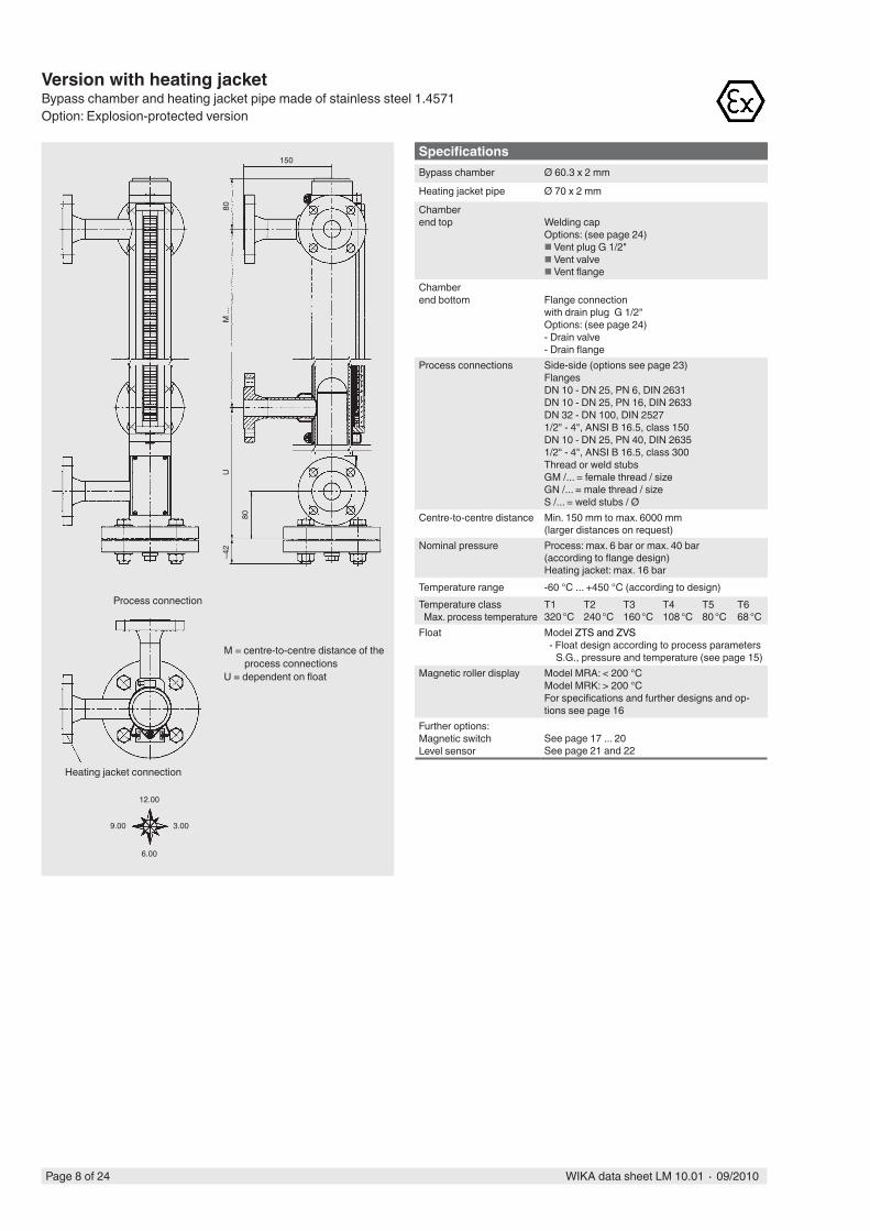
SpecificationsBypass chamber Ø 60.3 x 2 mm
Heating jacket pipe Ø 70 x 2 mm
Chamber end top Welding cap
Options: (see page 24) Vent plug G 1/2" Vent valve Vent flange
Chamber end bottom Flange connection
with drain plug G 1/2" Options: (see page 24)- Drain valve - Drain flange
Process connections Side-side (options see page 23) Flanges DN 10 - DN 25, PN 6, DIN 2631 DN 10 - DN 25, PN 16, DIN 2633 DN 32 - DN 100, DIN 2527 1/2" - 4", ANSI B 16.5, class 150DN 10 - DN 25, PN 40, DIN 2635 1/2" - 4", ANSI B 16.5, class 300 Thread or weld stubs GM /... = female thread / size GN /... = male thread / size S /... = weld stubs / Ø
Centre-to-centre distance Min. 150 mm to max. 6000 mm (larger distances on request)
Nominal pressure Process: max. 6 bar or max. 40 bar (according to flange design)Heating jacket: max. 16 bar
Temperature range -60 °C ... +450 °C (according to design)Temperature class Max. process temperature
T1 T2 T3 T4 T5 T6320 °C 240 °C 160 °C 108 °C 80 °C 68 °C
Float Model ZTS and ZVS - Float design according to process parameters
S.G., pressure and temperature (see page 15)Magnetic roller display Model MRA: < 200 °C
Model MRK: > 200 °C For specifications and further designs and op-tions see page 16
Further options: Magnetic switch Level sensor
See page 17 ... 20See page 21 and 22
Version with heating jacketBypass chamber and heating jacket pipe made of stainless steel 1.4571Option: Explosion-protected version
M = centre-to-centre distance of the process connections
U = dependent on float
Process connection
Heating jacket connection
12.00
6.00
9.00 3.00
150
~42
UM
...
80
80
Page 9 of 24WIKA data sheet LM 10.01 ∙ 09/2010
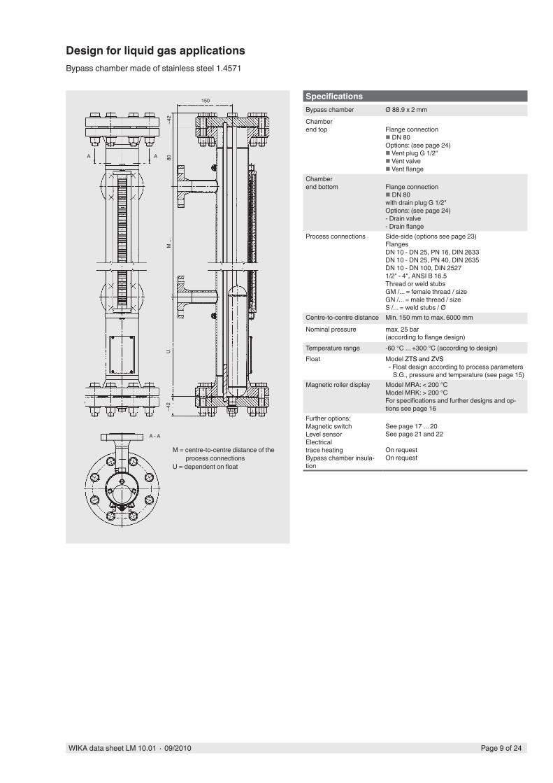
SpecificationsBypass chamber Ø 88.9 x 2 mm
Chamber end top Flange connection
DN 80Options: (see page 24) Vent plug G 1/2" Vent valve Vent flange
Chamber end bottom Flange connection
DN 80with drain plug G 1/2" Options: (see page 24)- Drain valve - Drain flange
Process connections Side-side (options see page 23) Flanges DN 10 - DN 25, PN 16, DIN 2633 DN 10 - DN 25, PN 40, DIN 2635 DN 10 - DN 100, DIN 2527 1/2" - 4", ANSI B 16.5 Thread or weld stubs GM /... = female thread / size GN /... = male thread / size S /... = weld stubs / Ø
Centre-to-centre distance Min. 150 mm to max. 6000 mm
Nominal pressure max. 25 bar (according to flange design)
Temperature range -60 °C ... +300 °C (according to design)Float Model ZTS and ZVS
- Float design according to process parameters S.G., pressure and temperature (see page 15)
Magnetic roller display Model MRA: < 200 °C Model MRK: > 200 °C For specifications and further designs and op-tions see page 16
Further options: Magnetic switch Level sensorElectrical trace heating Bypass chamber insula-tion
See page 17 ... 20See page 21 and 22
On request On request
M = centre-to-centre distance of the process connections
U = dependent on float
Design for liquid gas applicationsBypass chamber made of stainless steel 1.4571
150
~42
UM
...
80A A
A - A
~42

Page 10 of 24 WIKA data sheet LM 10.01 ∙ 09/2010
150
~35
150
~50
U =
...M
= ...
SpecificationsBypass chamber E-CTFE coated: Ø 64 x 2 mm
E-TFE coated: Ø 70 x 2 mmChamber end top Flange connection
Options: (see page 24) Vent flange
Chamber end bottom Flange connection
Options: (see page 24)- Drain flange
Process connections Side-side Flanges DN 25, PN 16, DIN 2633 DN 32 - DN 100, DIN 2527 1/2" - 4", ANSI B 16.5, class 150 Thread or weld stubs GM /... = female thread / size GN /... = male thread / size S /... = weld stubs / Ø
Centre-to-centre distance Min. 150 mm to max. 1900 mm(overall pipe length max. 2900 mm)With overall pipe length > 2900 mm: Bypass chamber separated with flange connection
Nominal pressure max. 16 bar
Temperature range depending on the mediumFloat Model ZTECS (material stainless steel 1.4571,
E- CTFE coated)Model ZVECS (material titanium 3.7035,
E- CTFE coated) - Float design according to process parameters
S.G., pressure and temperature (see page 15)Magnetic roller display Model MRA-M
For specifications and further designs and options see page 16
Further options: Magnetic switch Level sensorElectrical trace heating Bypass chamber insulation
See page 17 ... 20See page 21 and 22
On request
On requestM = centre-to-centre distance of the process connections
U = dependent on float
Version E-CTFE or E-TFE coatedBypass chamber made of stainless steel 1.4571
130/
150
Page 11 of 24WIKA data sheet LM 10.01 ∙ 09/2010
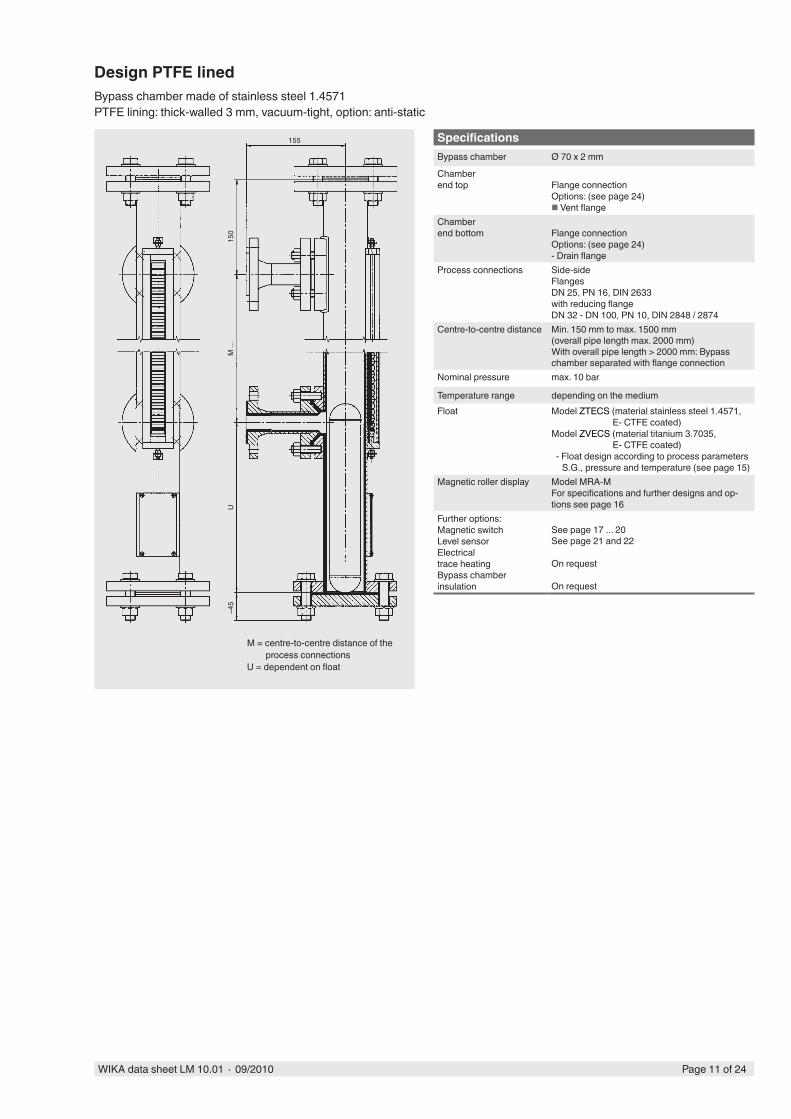
SpecificationsBypass chamber Ø 70 x 2 mm
Chamber end top Flange connection
Options: (see page 24) Vent flange
Chamber end bottom Flange connection
Options: (see page 24)- Drain flange
Process connections Side-side Flanges DN 25, PN 16, DIN 2633 with reducing flange DN 32 - DN 100, PN 10, DIN 2848 / 2874
Centre-to-centre distance Min. 150 mm to max. 1500 mm(overall pipe length max. 2000 mm)With overall pipe length > 2000 mm: Bypass chamber separated with flange connection
Nominal pressure max. 10 bar
Temperature range depending on the mediumFloat Model ZTECS (material stainless steel 1.4571,
E- CTFE coated)Model ZVECS (material titanium 3.7035,
E- CTFE coated) - Float design according to process parameters
S.G., pressure and temperature (see page 15)Magnetic roller display Model MRA-M
For specifications and further designs and op-tions see page 16
Further options: Magnetic switch Level sensorElectrical trace heating Bypass chamber insulation
See page 17 ... 20See page 21 and 22
On request
On request
M = centre-to-centre distance of the process connections
U = dependent on float
Design PTFE linedBypass chamber made of stainless steel 1.4571PTFE lining: thick-walled 3 mm, vacuum-tight, option: anti-static
155
~45
UM
...
150

Page 12 of 24 WIKA data sheet LM 10.01 ∙ 09/2010
SpecificationsBypass chamber Ø 63 x 3 mmChamber end top Flat top
Options: (see page 24) Vent plug G 1/2" Vent valve Vent flange
Chamber end bottom Fitting
Options: (see page 24)- Drain valve - Drain flange
Process connections Side-side flanges DN 15 - DN 50, PN 16Connection dimensions: ISO/DIN1/2“ - 2“, ANSI B 16.5, class 150Connection dimensions: ANSI B 16.5Material: UP - GF
Centre-to-centre distance Min. 200 mm to max. 4000 mm
Nominal pressure max. 4 bar
Temperature range Polypropylene max. 60 °C PVDF max. 80 °C
Float Model ZPPS (material Polypropylene)Model ZPFS (material PVDF) - Float length depending on S.G.For specifications see page 14
Magnetic roller display Model MRA-M For specifications and further designs and op-tions see page 16
Further options: Magnetic switch Level sensor
See page 17 ... 20See page 21 and 22
M = centre-to-centre distance of the process connections
U = dependent on float
Plastic versionBypass chamber and float made of polypropylene or PVDF

Page 13 of 24WIKA data sheet LM 10.01 ∙ 09/2010
Immersion depth table in relation to the specific gravity of the medium (kg/m3)
PVDF+ 80 °CMax. 6 barMax. 9 bar50 mmZPFS ...
PP+ 60 °CMax. 6 barMax. 9 bar50 mmZPPS ...
MaterialOperating temperatureWorking pressureTest pressureDiameterFloat model
150 200 250 300 350295 393 491 589 687290 335 385 435 480
Float L (mm)Volume (cm3)Weight (g)
150 200 250 300 350295 393 491 589 687260 285 310 335 360
- - - - -
- - - - -
- - - - -
1230 1000 890 820 760
1340 1070 930 850 790
1480 1140 980 890 810
1640 1220 1030 920 840
1850 1310 1090 960 870
2110 1420 1150 1010 910
2460 1550 1230 1050 940
2950 1710 1310 1110 980
- 1900 1400 1170 1020
- 2130 1510 1230 1060
- 2440 1630 1300 1110
- 2840 1780 1380 1160
- - 1960 1480 1220
- 2180 1580 1290
- 2450 1700 1360
- 2800 1850 1440
- - 2010 1530
- - 2220 1630
- 2460 1750
- 2770 1880
- - 2040
- - 2220
- - 2440
- 2720
- -
- -
- -
- -
-
-
-
-
-
- - - - -
- - - - -
- - - - -
1100 850 720 630 570
1200 910 750 660 590
1320 970 790 680 610
1470 1040 830 710 630
1660 1120 880 740 650
1890 1210 930 780 680
2210 1320 990 810 710
2650 1450 1050 850 730
- 1610 1130 900 760
- 1810 1210 950 800
- 2070 1320 1000 830
- 2420 1440 1070 870
- 2900 1580 1140 920
- 1750 1220 960
- 1970 1310 1020
- 2260 1420 1080
- 2630 1550 1150
- - 1710 1220
- 1900 1310
- 2130 1410
- 2440 1530
- 2840 1670
- - 1830
- 2040
- 2290
- 2620
- -
- -
-
-
-
-
-
0
10
20
30
40
50
60
70
80
90
100
110
120
130
140
150
160
170
180
190
200
210
220
230
240
250
260
270
280
290
300
310
320
330
340
350
Plastic cylindrical floatmade of polypropylene or PVDF
Emersionheight in mm
Nominal height
Note: The optimum float will be selected after a feasibility test carried out by WIKA.

Page 14 of 24 WIKA data sheet LM 10.01 ∙ 09/2010
MaterialOperating temperatureWorking pressureTest pressureDiameterFloat model
Float L (mm)Volume (cm3)Weight (g)
Nominal height
Note: The optimum float will be selected after a feasibility test carried out by WIKA.
Stainless steel 1.4571- 40 °C to + 250 °CMax. 30 barMax. 45 bar50 mmZVSS ...
Titanium 3.7035- 40 °C to + 250 °CMax. 30 barMax. 45 bar50 mmZTSS ...
150 200 250 300 350 400 450262 360 458 556 654 753 851256 300 332 368 415 455 485
- - - - - - -
- - - - - - -
- - - - - - -
1170 950 800 720 680 640 600
1280 1010 840 740 700 660 610
1420 1080 880 780 720 680 630
1600 1160 930 810 750 700 650
1820 1260 980 850 780 720 660
2110 1370 1050 890 810 740 680
2520 1500 1110 930 840 770 700
- 1670 1190 980 870 790 720
- 1870 1280 1030 910 820 740
- 2130 1390 1090 950 850 770
- 2480 1510 1160 1000 890 790
- 2960 1660 1240 1050 920 820
- - 1840 1320 1100 960 850
- 2070 1420 1160 1000 880
- 2360 1540 1230 1050 910
- 2740 1680 1310 1090 940
- - 1840 1390 1150 980
- - 2040 1490 1210 1020
- 2290 1610 1280 1070
- 2620 1740 1350 1110
- - 1890 1430 1170
- - 2080 1530 1220
- - 2310 1640 1290
- 2590 1760 1360
- 2950 1900 1440
- - 2080 1530
- - 2280 1630
- - 2530 1740
- 2840 1880
- - 2030
- - 2210
- - 2430
- - 2690
- -
- -
- -
- -
- -
-
-
-
-
-
Immersion depth table in relation to the specific gravity of the medium (kg/m3)
0
10
20
30
40
50
60
70
80
90
100
110
120
130
140
150
160
170
180
190
200
210
220
230
240
250
260
270
280
290
300
310
320
330
340
350
360
370
380
390
400
410
420
430
440
450
- - - - - - -
- - - - - - -
- - - - - - -
770 760 640 560 510 480 460
850 810 670 580 530 500 470
940 860 700 600 540 510 480
1050 930 740 630 560 530 490
1200 1000 790 660 580 540 500
1400 1090 830 690 610 560 520
6070 1200 890 720 630 580 530
2070 1330 950 760 660 600 550
2720 1500 1030 800 690 620 570
- 1710 1110 850 720 640 580
- 1980 1210 900 750 670 600
- 2370 1330 960 790 690 620
- 2930 1470 1030 830 720 640
- 1650 1110 870 750 670
- 1880 1200 930 790 690
- 2190 1310 980 820 720
- 2610 1440 1050 860 740
- - 1590 1120 910 780
- 1790 1210 960 810
- 2040 1310 1010 850
- 2370 1420 1080 890
- 2830 1560 1150 930
- - 1730 1230 980
- 1950 1320 1030
- 2220 1430 1090
- 2580 1560 1160
- - 1710 1240
- - 1900 1320
- 2130 1420
- 2430 1540
- 2820 1680
- - 1840
- - 2040
- 2290
- 2620
- -
- -
- -
-
-
-
-
-
150 200 250 300 350 400 450262 360 458 556 654 753 851169 240 265 287 312 342 368
Emersion height in mm
Cylindrical float, design with beadsmade of stainless steel or titanium
Page 15 of 24WIKA data sheet LM 10.01 ∙ 09/2010
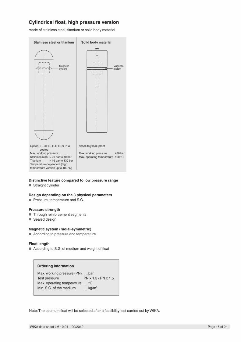
Cylindrical float, high pressure versionmade of stainless steel, titanium or solid body material
Magnetic system
Stainless steel or titanium
Magnetic system
Solid body material
Option: E-CTFE-, E-TFE- or PFA coated
Max. working pressure: Stainless steel > 20 bar to 40 barTitanium > 16 bar to 130 barTemperature-dependent (high temperature version up to 400 °C)
absolutely leak-proof
Max. working pressure 420 barMax. operating temperature 100 °C
Distinctive feature compared to low pressure range ■ Straight cylinder
Design depending on the 3 physical parameters ■ Pressure, temperature and S.G.
Pressure strength ■ Through reinforcement segments ■ Sealed design
Magnetic system (radial-symmetric) ■ According to pressure and temperature
Float length ■ According to S.G. of medium and weight of float
Note: The optimum float will be selected after a feasibility test carried out by WIKA.
Ordering information
Max. working pressure (PN) .... bar Test pressure PN x 1.3 / PN x 1.5Max. operating temperature .... °CMin. S.G. of the medium .... kg/m3

Page 16 of 24 WIKA data sheet LM 10.01 ∙ 09/2010
M = measuring rangeL = M + 83
Magnetic roller displays (red and white)Material Crastin PBT and ceramic, ingress protection IP 65
M = measuring rangeL = M + 83
Housing anodised aluminium Housing aluminium, stainless steel sheathed
Display roller material Crastin PBT Ceramic
Cover Makrolon PC GlassMax. ambient temperature 200 °C 450 °C
with sight glass extender and purge(with bypass chamber insulation)
Sight glass extender
M = measuring rangeL = M + 83I = insulation thickness
Aluminium with adhesive foil, cm-graduationmax. ambient temperature for the adhesive foil: 100 °CAluminium or stainless steel engraved, graduation selectable
M = measuring rangeL = M + 83
49
L ...
40
M ..
.23

Page 17 of 24WIKA data sheet LM 10.01 ∙ 09/2010
Specifications
Contact Reed contact
Contact type 1 change-over contact
Switch behaviour Bistable
Contact rating AC 230 V, 60 VA, 1 A DC 230 V, 30 W, 0.5 A
NAMUR circuit For connection to control circuit per EN 60947-5-6
Option Ex version Only for connection to a certified intrinsically safe circuit with max. 100 mA and max. 30 VIgnition protection type: II 1 G EEx ia IIC T6 - T3 LCIE 01 ATEX 6047 X
Ambient temperature Standard: max. 90 °C with silicone cable: max. 150 °C with coupler plug: max. 85 °C Ex version: T6 to 85 °C
Electrical connection Connection cable 1 m PVC grey(3 x 0.75 mm2) 1 m PVC blue
1 m PURCoupler connector
Housing Aluminium, anodised
Ingress protection IP 65 per EN 60529 / lEC 529
Option magnetic switch
Switch point
Float
Magnetic switch
Magnetic switches serve to detect the limits of filling levels.They generate a binary signal which can be transmitted to downstream monitoring and control devices.
blue (1)
brown (2)
black (3)
blue (1)
brown (2)
black (3)
blue (1)
brown (2)
black (3)
22 Ohm 1K 10K
10K
Standard version
Example for mounting
with connection cable
100
with coupler plug
Sliding block for mounting on the left or right of the magnetic roller display
42
30 255.5
16
50
Pg 9 Pg 9
100
42
30 25
5.5
16
50
≈188
Contact protection measures
Magnetic switch
RC module
Magnetic switch
Diode Load
Connection diagrams1 switch pointWiring for operation with a PLC
1 switch pointInitiator equivalent circuit per EN 60947-5-6
Magnetic roller display
Load
Sliding block for mounting on the left or right of the magnetic roller display

Page 18 of 24 WIKA data sheet LM 10.01 ∙ 09/2010
Version with terminal box
Sliding block
Sliding block
Terminal box
Explosion-protected version, flameproof enclosure (aluminium)II 2 G EEx d IIC T6 - T3 LCIE 01 ATEX 6047 X
Sliding block for mounting on the left or right of the magnetic roller display
100
42
30
255.5
16
Cable gland for armoured cables
Cable gland for cables without armour
100
~80 59
3050
25
Specifications
Contact Reed contact
Contact type 1 change-over contact
Switch behaviour Bistable
Contact rating AC 230 V, 60 VA, 1 A DC 230 V, 30 W, 0.5 A
NAMUR circuit For connection to control circuit per EN 60947-5-6
Option Ex version Only for connection to a certified intrinsically safe circuit with max. 100 mA and max. 30 VIgnition protection type: II 1 G EEx ia IIC T6 - T3 LCIE 01 ATEX 6047 X
Ambient temperature Standard: max. 150 °C Ex version: T6 to 85 °C T5 to 100 °C T4 to 135 °C T3 to 150 °C
Electrical connection Terminal box
Housing Aluminium, anodised
Ingress protection IP 65 per EN 60529 / lEC 529
For contact protection measures see page 17
Specifications
Contact Reed contact
Contact type 1 change-over contact
Switch behaviour Bistable
Contact rating AC 230 V, 60 VA, 1 A DC 230 V, 30 W, 0.5 A
NAMUR circuit For connection to control circuit per EN 60947-5-6
Ambient temperature T6 to 85 °C T5 to 100 °C T4 to 135 °C T3 to 150 °C
Electrical connection Connection cable 1 m PVC grey(3 x 0.75 mm2) 1 m PVC blue
1 m PUR yellow 1 m PUR yellow with armour 1 m silicone
Housing Aluminium, anodised
Ingress protection IP 68 per EN 60529 / lEC 529
For contact protection measures see page 17
50

Page 19 of 24WIKA data sheet LM 10.01 ∙ 09/2010
100
21,3
50
100
21,3
50
Mounting rod
Mounting rod
Mounting ringMounting ring
Switch point
Switch point
Stainless steel version Explosion-protected version, flameproof enclosure (stainless steel)II 2 G EEx d IIC T6 - T3 LCIE 01 ATEX 6047 X
Cable gland for armoured cables
Cable gland for cables without armour
Specifications
Contact Reed contact
Contact type 1 change-over contact
Switch behaviour Bistable
Contact rating AC 230 V, 60 VA, 1 A DC 230 V, 30 W, 0.5 A
NAMUR circuit For connection to control circuit per EN 60947-5-6
Option Ex version Only for connection to a certified intrinsically safe circuit with max. 100 mA and max. 30 VIgnition protection type: II 1 G EEx ia IIC T6 - T3 LCIE 01 ATEX 6047 X
Ambient temperature Standard: max. 90 °C with silicone cable: max. 150 °C Ex version: T6 to 85 °C
Electrical connection Connection cable 1 m PVC grey(3 x 0.75 mm2) 1 m PVC blue
1 m silicone
Housing Stainless steel 1.4571
Ingress protection IP 65 per EN 60529 / lEC 529
For contact protection measures see page 17
Specifications
Contact Reed contact
Contact type 1 change-over contact
Switch behaviour Bistable
Contact rating AC 230 V, 60 VA, 1 A DC 230 V, 30 W, 0.5 A
NAMUR circuit For connection to control circuit per EN 60947-5-6
Ambient temperature T6 to 85 °C T5 to 100 °C T4 to 135 °C T3 to 150 °C
Electrical connection Connection cable
1 m PVC grey
(3 x 0.75 mm2) 1 m PUR yellow 1 m PUR yellow with armour 1 m silicone
Housing Stainless steel 1.4571
Ingress protection IP 68 per EN 60529 / lEC 529
For contact protection measures see page 17

Page 20 of 24 WIKA data sheet LM 10.01 ∙ 09/2010
80
~67
75~110
M 20 x 1,5
75~7
0
80
~110
M 20 x 1,5
High temperature version
Specifications
Contact Reed contact
Contact type 1 change-over contact
Switch behaviour Bistable
Contact rating AC 230 V, 60 VA, 1 A DC 230 V, 30 W, 0.5 A
NAMUR circuit For connection to control circuit per EN 60947-5-6
Ambient temperature max. 380 °C
Electrical connection Terminal box
Housing Aluminium
Ingress protection IP 65 per EN 60529 / lEC 529
For contact protection measures see page 17
Specifications
Contact Inductive proximity sensor SJ 3.5-SN
Contact type High alarm Low alarm
Switch behaviour Bistable
Nominal voltage DC 8 V (Ri~1 kOhm)
Max. residual ripple < 5 %
Power supply UB 5 ... 25 V
Current supply active area free active area covered
> 3 mA < 1 mA
Control cable - max. resistance < 100 Ohm
160 μH
20 nF
Ambient temperature -40 °C to +100 °C
Housing Aluminium
Ingress protection IP 65 per EN 60529 / lEC 529
Other versions on request
Inductive proximity sensor design
Page 21 of 24WIKA data sheet LM 10.01 ∙ 09/2010
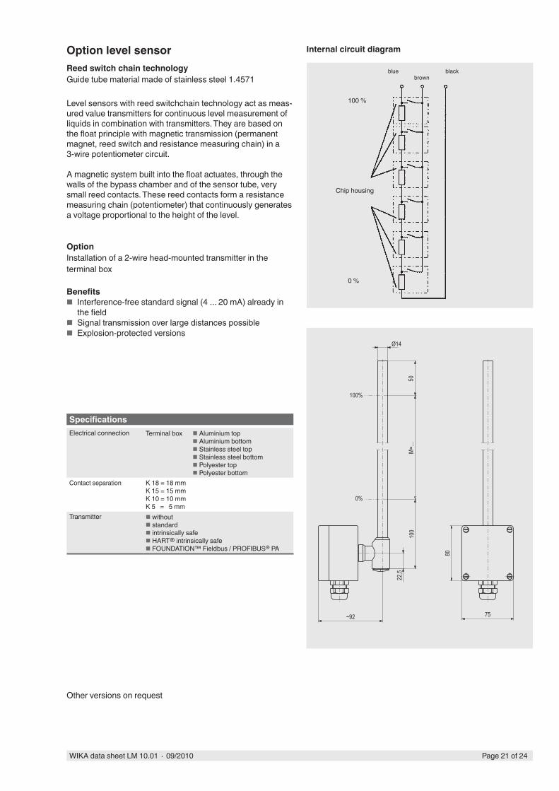
Option level sensorReed switch chain technologyGuide tube material made of stainless steel 1.4571
black
Level sensors with reed switchchain technology act as meas-ured value transmitters for continuous level measurement of liquids in combination with transmitters. They are based on the float principle with magnetic transmission (permanent magnet, reed switch and resistance measuring chain) in a 3-wire potentiometer circuit.
A magnetic system built into the float actuates, through the walls of the bypass chamber and of the sensor tube, very small reed contacts. These reed contacts form a resistance measuring chain (potentiometer) that continuously generates a voltage proportional to the height of the level.
OptionInstallation of a 2-wire head-mounted transmitter in the terminal box
Benefits ■ Interference-free standard signal (4 ... 20 mA) already in
the field ■ Signal transmission over large distances possible ■ Explosion-protected versions
Internal circuit diagram
bluebrown
100 %
0 %
Other versions on request
SpecificationsElectrical connection Terminal box Aluminium top
Aluminium bottom Stainless steel top Stainless steel bottom Polyester top Polyester bottom
Contact separation K 18 = 18 mmK 15 = 15 mm K 10 = 10 mm K 5 = 5 mm
Transmitter without standard intrinsically safe HART® intrinsically safe FOUNDATION™ Fieldbus / PROFIBUS® PA
~92
22,5
100
0%
M=…
100%
Ø14
50
80
75
Chip housing

Page 22 of 24 WIKA data sheet LM 10.01 ∙ 09/2010
108
30
L = . .
.
50M
= . .
.
Ø 52
0 %
100 %
Sensor tube Ø 12 mm
Sensor housing
Cable gland M16 x 1.5
Option level sensorMagnetostrictive, high-resolution measuring principleGuide tube material made of stainless steel 1.4571
Level sensors with a magnetostrictive, high-resolution measuring principle act as measured value transmitters for continuous level measurement of liquids and are based on identifying the position of a magnetic float following the magnetostrictive measuring principle. The sensors are mounted externally on a bypass level sensor.
The measuring process is initiated by a current impulse. This current generates an axial magnetic field along the length of a wire made of magnetostrictive material, which is held under tension inside the sensor tube. The bypass level indicator float, which sits on the liquid surface, is fitted with permanent magnets. The magnetic field of the float is at right angles to the impulse magnetic field. When the pulse reaches the float, the two magnetic fields interact and a torsional force results. A piezoceramic pick-up in the sensor housing at the end of the wire converts this into an electrical signal.
The measured propagation delay enables the origination point, and thus the float position, to be determined with high accuracy.
Wire
Torsion wave
Impulse magnetic field
Torsion wave
Permanent magnet
Permanent magnetic field
Illustration of the principle
Specifications
Electrical connection Sensor housing Stainless steel 1.4301
Sensor tube diameter 12 mm
Sensor tube length L max. 6000 mm
Temperature range standard Medium: -45 ... +125 °C
Sensor housing: -40 ... +85 °COption High and low temperature version: -200 ... +200 °C
Ex version:Temperature class Process temperature, max. Ambient temperature at the sensor housing, max.
T3 T4 T5 T685 °C 100 °C 135 °C 150 °C
40 °C 55 °C 85 °C 85 °C
Ex version:Signal and supply circuit In intrinsically safe version EEx ib IIC
Ui < 30 V ; Ii < 200 mA ; Li < 250 µH ; Ci < 5 nF
Output signal 4 ... 20 mA, 2-wire
Power supply DC 10 ... 30 V
Error message Adjustable to 3.6 mA or 21.5 mA
Measuring accuracy < ±0.5 mm
Resolution < 0.1 mm
Analogue component ±0.1 % (20 °C) + 0.005 % / K
Load 900 Ohm at UB = DC 30 V650 Ohm at UB = DC 24 V100 Ohm at UB = DC 12 V
Ingress protection IP 68 per EN 60529 / lEC 529

Page 23 of 24WIKA data sheet LM 10.01 ∙ 09/2010
1Welding neck flange
up to DN 25
2Blind flange
above DN 32
3Threaded coupling GN ...
(male thread)
4Threaded coupling GM ...
(female thread)
5Weld stub S ...
Option process connection
6Standard version
process connections side-side
71 process connection side
1 process connection vertical (top)
82 process connections
to DIN 11851 Lower process connection via
eccentric reducer
92 process connections
vertical (top/bottom) Option: support bracket
Examples

Page 24 of 24 WIKA data sheet LM 10.01 ∙ 09/2010
WIKA Alexander Wiegand SE & Co. KGAlexander-Wiegand-Straße 3063911 Klingenberg/GermanyTel. (+49) 9372/132-0Fax (+49) 9372/132-406E-mail [email protected]
Upper bypass chamber end
1Welding cap
Lower bypass chamber end
2Flat top with
vent plug G 1/2"
3Flange connection with
vent plug G 1/2"
4Flange connectione.g. sealing faces
groove/tongue per DIN 2512
5Flat top with vent flange
6Flange connection
vent flange
7Flat top with vent valve
8Flange connection
with vent valve
9Flange connection
with drain plug G 1/2"
10Flange connection e.g.
sealing faces groove/tongue per DIN 2512 with drain plug G 1/2"
11Flange connection with drain nozzle
12Flange connection
with drain valve
13Flange connection with drain flange
Ordering informationModel / Version / Process connection / Bypass chamber diameter / Centre-to-centre distance M ... / Process specifications (operating temperature and working pressure, S.G.) / Contact separation / Electrical connection / Options
The specifications given in this document represent the state of engineering at the time of publishing.We reserve the right to make modifications to the specifications and materials.
Option bypass chamber end (on request with dampening spring)
09/2
010
GB