c 2008 vijay raman - university of illinois at...
TRANSCRIPT

c© 2008 Vijay Raman

DEALING WITH ADJACENT CHANNEL INTERFERENCE EFFECTS INMULTICHANNEL, MULTI-INTERFACE WIRELESS NETWORKS
BY
VIJAY RAMAN
B.Tech., Anna University, Chennai, 2004
THESIS
Submitted in partial fulfillment of the requirementsfor the degree of Master of Science in Electrical and Computer Engineering
in the Graduate College of theUniversity of Illinois at Urbana-Champaign, 2008
Urbana, Illinois
Adviser:
Professor Nitin H. Vaidya

ABSTRACT
Multichannel, multiradio wireless networks provide the flexibility to utilize the
available spectrum efficiently for achieving improved system performance. Using
multiple channels simultaneously allows for increased spatial reuse by increasing
the number of concurrent transmissions in the network. Furthermore, if multiple
channels are used within a neighborhood, the amount of contention between the
nodes operating on the channel is reduced.
The performance of a multichannel, multiradio wireless network, however, is
often restricted by interference due to concurrent transmissions on the same and
adjacent channels. These interference effects may be due to signal leakage from
simultaneous traffic activity by the multiple radios within a node or by a neighbor-
ing node. These interference effects can be avoided by performing an intelligent
channel allocation to choose a proper set of channels that do not interfere with
each other.
In this thesis, we first characterize the adjacent channel interference effects
in a multichannel, multiradio wireless network. We then propose a distributed
channel allocation algorithm that makes use of the traffic information from the
wireless cards to perform an interference-free channel allocation that is optimal.
We demonstrate the performance benefit achieved by our algorithm using actual
implementations on a multichannel, multiradio wireless testbed.
ii

To my parents, for their love and support.
iii

ACKNOWLEDGMENTS
I would like to thank my adviser, Dr. Nitin Vaidya, for guiding me through the
research and thesis writing process. I would like to acknowledge the National
Science Foundation (NSF) for financially supporting my research. I would like to
specially thank my first mentors in the group, Vartika Bhandari and Cheolgi Kim.
Thanks to Rishi Bhardwaj, Nistha Tripathi, Santosh Vairavan, Thomas Shen, and
Kyungtae Kang for sharing their ideas and knowledge. Thanks to Anthony Halley,
Simone Merlin, and Helen Xi for their support and motivation. I would also like
to thank Tae Hyun Kim, Guanfeng Liang, Chun-cheng Chen, and Lu-chuan Kung
for their valuable suggestions and useful discussions. Last but not least, thanks
to my family and valuable group of friends for their support.
iv

TABLE OF CONTENTS
LIST OF TABLES . . . . . . . . . . . . . . . . . . . . . . . . . . . . . . . vii
LIST OF FIGURES . . . . . . . . . . . . . . . . . . . . . . . . . . . . . . viii
LIST OF ABBREVIATIONS . . . . . . . . . . . . . . . . . . . . . . . . . x
CHAPTER 1 INTRODUCTION . . . . . . . . . . . . . . . . . . . . . . 1
CHAPTER 2 RELATED WORK . . . . . . . . . . . . . . . . . . . . . . 52.1 Adjacent Channel Interference Effects . . . . . . . . . . . . . . . . 52.2 Channel Allocation Algorithms . . . . . . . . . . . . . . . . . . . 7
2.2.1 Centralized algorithms . . . . . . . . . . . . . . . . . . . . 72.2.2 Distributed algorithms . . . . . . . . . . . . . . . . . . . . 92.2.3 Joint channel allocation and routing . . . . . . . . . . . . 10
CHAPTER 3 BACKGROUND . . . . . . . . . . . . . . . . . . . . . . . 113.1 Testbed Overview . . . . . . . . . . . . . . . . . . . . . . . . . . . 113.2 Multichannel Protocol Operation . . . . . . . . . . . . . . . . . . 123.3 System Architecture . . . . . . . . . . . . . . . . . . . . . . . . . 14
3.3.1 Channel abstraction layer . . . . . . . . . . . . . . . . . . 15
CHAPTER 4 INTERFERENCE EFFECTS . . . . . . . . . . . . . . . . 164.1 Spectrum Analyzer-Based Experiments . . . . . . . . . . . . . . . 164.2 Interference Effects in a Network . . . . . . . . . . . . . . . . . . 18
4.2.1 Cochannel and adjacent channel interference effects . . . . 194.2.2 Number of hops over which interference exists . . . . . . . 23
CHAPTER 5 CHANNEL ALLOCATION ALGORITHM . . . . . . . . . 265.1 Channel Assignment Problem Formulation . . . . . . . . . . . . . 26
5.1.1 Network and interference model . . . . . . . . . . . . . . . 265.2 A Simple Load Balancing Channel Allocation Algorithm . . . . . 28
5.2.1 Improved simple load-balancing algorithm . . . . . . . . . 295.3 Traffic-Aware Channel Allocation Algorithm . . . . . . . . . . . . 31
v

CHAPTER 6 IMPLEMENTATION DETAILS . . . . . . . . . . . . . . . 356.1 User Space Entity . . . . . . . . . . . . . . . . . . . . . . . . . . . 356.2 Interaction with the Kernel Space . . . . . . . . . . . . . . . . . . 366.3 Invoking the Traffic-Aware Algorithm . . . . . . . . . . . . . . . . 37
CHAPTER 7 PERFORMANCE RESULTS . . . . . . . . . . . . . . . . 397.1 Two Flows at Each Node . . . . . . . . . . . . . . . . . . . . . . . 407.2 One Flow at Each Node . . . . . . . . . . . . . . . . . . . . . . . 43
CHAPTER 8 CONCLUSIONS AND FUTURE WORK . . . . . . . . . . 46
REFERENCES . . . . . . . . . . . . . . . . . . . . . . . . . . . . . . . . . 48
vi

LIST OF TABLES
4.1 IEEE 802.11a channels and maximum power restrictions al-lowed by the FCC in the U.S. . . . . . . . . . . . . . . . . . . . . 17
7.1 Throughput (in Mbps) comparison between the load-balancingand traffic-aware algorithms - two flows at each node. . . . . . . . 40
7.2 Throughput (in Mbps) comparison between the load-balancingand traffic-aware algorithms for TCP flows. . . . . . . . . . . . . . 43
7.3 Throughput (in Mbps) comparison between the load-balancingand traffic-aware algorithms - only one flow at each node. . . . . . 44
7.4 Throughput (in Mbps) comparison between the load-balancingand traffic-aware algorithms - for one TCP flow at each node. . . 45
vii

LIST OF FIGURES
3.1 A Soekris net board used in our testbed. . . . . . . . . . . . . . . 123.2 Example multichannel protocol operation. . . . . . . . . . . . . . 13
4.1 Spectrum analyzer plots for PCMCIA card for channels (fromleft to right and top to bottom) 36, 44, 52, 60, 64, 149, and 161. . 18
4.2 Spectrum analyzer plots for mini-PCI card for channels (fromleft to right and top to bottom) 36, 44, 52, 60, 64, 149, and 161. . 18
4.3 IEEE 802.11a clear channel assessment scheme. . . . . . . . . . . 194.4 Four-node network topology used for interference experiments. . . 204.5 Four-node network topology from the visualization tool. . . . . . . 204.6 Throughput results for four flows in the form of ring. . . . . . . . 214.7 Four-node network topology showing two adjacent flows. . . . . . 224.8 Four-node network with two flows from the visualization tool. . . 224.9 Throughput results for two adjacent flows. . . . . . . . . . . . . . 224.10 Linear network topology used for interference experiments. . . . . 234.11 Linear network topology from the visualization tool. . . . . . . . . 234.12 Throughput results for the linear network. . . . . . . . . . . . . . 24
5.1 A 10-node network topology used for comparing the load bal-ancing algorithms. . . . . . . . . . . . . . . . . . . . . . . . . . . 30
5.2 A 10-node network from the visualization tool. . . . . . . . . . . . 305.3 Throughput comparison between the simple load balancing al-
gorithm using a subset containing five channels and that usingmore contiguous channels. . . . . . . . . . . . . . . . . . . . . . . 31
6.1 Net-X system architecture with the block containing the channelallocation protocol highlighted. . . . . . . . . . . . . . . . . . . . 37
7.1 Comparison between the load-balancing and traffic-aware algo-rithms - two flows at each node. . . . . . . . . . . . . . . . . . . . 41
7.2 Comparison between the load-balancing and traffic-aware algo-rithms for TCP flows. . . . . . . . . . . . . . . . . . . . . . . . . . 42
7.3 A 10-node network topology with one flow at each node. . . . . . 437.4 Comparison between the load-balancing and traffic-aware algo-
rithms - only one flow at each node. . . . . . . . . . . . . . . . . . 44
viii

7.5 Comparison between the load-balancing and traffic-aware algo-rithms for one TCP flow at each node. . . . . . . . . . . . . . . . 45
ix

LIST OF ABBREVIATIONS
AP Access Point
CCA Clear Channel Assessment
ETT Estimated Transmission Time
FDMA Frequence Division Multiple Access
IOCTL Input-Output Control
MCMI Multichannel Multi-interface
NIC Network Interface Card
TCP Transmission Control Protocol
TDMA Time Division Multiple Access
UDP User Datagram Protocol
WLAN Wireless Local Area Network
x
CHAPTER 1
INTRODUCTION
Multichannel, multi-interface (MCMI) wireless networks provide the flexibility to
utilize the available spectrum efficiently to achieve improved system performance
by allowing for more concurrent transmissions in the network. Kyasanur and
Vaidya [1] have shown that the capacity of a multichannel wireless network with
n randomly distributed nodes scales linearly with the number of channels when
the ratio of the number of channels to the number of interfaces is of the order
of O(log n). For practical networks, this would mean that we can achieve higher
throughputs by utilizing as many channels as possible depending on the wireless
technology used. For instance, IEEE 802.11a specifies 12 nonoverlapping channels
in the 5 GHz band for communication. The devices that currently use 802.11a,
however, operate on only one of these channels at any point of time. Better
performance can be obtained if the devices can use more than one channel simul-
taneously. However, the main challenge lies in designing protocols and algorithms
for utilizing all the available channels efficiently.
There are several practical issues that we need to consider while designing a
multichannel wireless network. For example, it is desirable to ensure that the
connectivity of a multichannel network is equivalent to that of a single channel
network. We can address this issue by allowing the wireless interfaces (or radios)1
in a node to switch across channels. Furthermore, we can have multiple inter-
faces in a node, and have a few of them receive traffic from other nodes, while
1The terms interfaces and radios are used interchangeably in this thesis.
1

the remaining interfaces are used for sending traffic. However, due to the close
proximity of the radios within a node, there could be a significant throughput
loss due to signal leakage when the radios operate on the same or adjacent chan-
nels. This imposes a restriction on the number of channels that could be used, as
the resulting interference effects can reduce the performance of the network. The
signal leakage from adjacent channels may be possible even when the adjacent
channels are nonoverlapping (as in IEEE 802.11a). This is due to improper signal
processing at the wireless cards and poor filter characteristics.
The adjacent channel interference effects can be minimized by choosing the
transmission channels carefully by making sure that nearby links are on non-
adjacent channels. However, due to the dynamic nature of the links in a wireless
network, the channel allocation should be adaptable to the traffic characteristics.
Furthermore, care should be taken that no single channel is overloaded (i.e., re-
used more when compared to other channels) within a neighborhood as this may
affect the concurrency in the network (number of simultaneous transmissions).
Additionally, the amount of control messages exchanged for executing the channel
allocation algorithm in a distributed fashion should be minimal.
A good channel allocation algorithm should, therefore, have the following prop-
erties:
1. Load balancing: all channels should be evenly distributed within a neigh-
borhood so that no single channel is overloaded.
2. Interference-free allocation: the allocation should minimize the cochannel
and adjacent channel interference in the network.
3. The number of control messages exchanged between the nodes for the pur-
pose of channel allocation has to be minimal.
2

While ensuring a load balanced channel allocation can indirectly minimize the
same channel transmissions in the network (by ensuring that no single channel
is used more often in a neighborhood), adjacent channel interference is difficult
to tackle and requires sufficient intelligence from the network. Performing the
channel allocation in a distributed fashion makes the problem more complicated.
A simple way to achieve these requirements is to use only the nonadjacent channels
for channel allocation. However, as we will show later, this technique reduces
the overall network throughput as it brings down the number of simultaneous
transmissions in the network at any time. It is, therefore, desirable to design a
channel allocation algorithm that can use all the available channels efficiently.
In this thesis, we propose a channel allocation algorithm that utilizes all the
channels efficiently, and show that we achieve a significant improvement in the
network throughput by avoiding adjacent channel interference. The main contri-
butions of this thesis are:
• Characterizing the adjacent channel interference effects in a multichannel,
multiradio wireless network using experiments on an actual testbed.
• An experimental analysis of the simple distributed load-balancing channel
assignment algorithm that was previously used in the testbed, which avoids
interference by using only 5 out of 12 802.11a channels. We show that this
simple algorithm can achieve a higher system-wide throughput if all the
available channels are used instead of using only a subset of channels.
• A traffic-aware channel allocation algorithm that chooses nonadjacent chan-
nels depending on the traffic conditions. We have demonstrated the per-
formance benefit of our traffic-aware algorithm using experimental results
based on an implementation of the algorithm on the testbed.
3

The remainder of the thesis is organized as follows. In Chapter 2 we present a
survey of existing literature on adjacent channel interference effects and channel
allocation algorithms for multichannel, multiradio wireless networks. In Chap-
ter 3, we provide a background on the multichannel testbed that is used for ex-
periments. In Chapter 4, we empirically characterize the cochannel and adjacent
channel interference effects in our testbed. In Chapter 5, we discuss the shortcom-
ings of the simple load-balancing algorithm and present a traffic-aware channel
allocation algorithm. In Chapter 6, we provide the implementation details of the
traffic-aware algorithm in the testbed. In Chapter 7, we discuss the performance
benefits of the traffic-aware algorithm over the simple load-balancing algorithm,
and we conclude in Chapter 8.
4

CHAPTER 2
RELATED WORK
Several experimental studies have been carried out in the literature for address-
ing the issue of adjacent channel interference in multichannel wireless networks.
Furthermore, a lot of work has been devoted for understanding the causes of the
interference and ways to mitigate them. Most of the solutions suggest efficient
channel allocation and proper hardware management for minimizing the adjacent
channel interference effects. In this section, we provide a brief survey on the var-
ious work that addresses the interference and channel allocation problems. We
categorize our survey into two subsections. The first section discusses the re-
lated work on adjacent channel interference effects and the second section surveys
channel allocation algorithms for multichannel, multi-interface wireless networks.
2.1 Adjacent Channel Interference Effects
Adjacent channel interference is mainly due to overlap in the channel spectrum.
For example, in 802.11b there are only three nonoverlapping channels (namely
channels 1, 6, and 11). In [2], the authors argue that the partially overlapping
channels of 802.11b can be considered as an advantage by using them for routing
data between nodes operating on nonoverlapping channels. The authors show that
the degree of interference due to the partial overlap of the channels is a function
of both the spectral separation of the channels and the spatial separation of the
nodes. Another work [3] uses the same model as [2], and shows that 802.11a/g
5

is also not free from adjacent channel interference effects. The authors show that
significant interference exists between adjacent channels within a node even when
directional antennas are used. Moreover, the paper claims that the clear channel
assessment (CCA) in 802.11a/g can detect adjacent channel transmissions and
backoff unnecessarily. Multiple radios are often used in multichannel networks to
exploit the full benefit. However, there can be practical limitations on the num-
ber of radios that could be used per node due to adjacent channel interference
between the radios. For example, in [4], the authors identify that no more than
two wireless cards can be used within a node for achieving reasonable through-
put performance. Furthermore, there has to be an adequate separation between
the antennas of the two wireless cards even though orthogonal channels are used
among the interfaces. Another experimental study [5] measures the throughput
and interference between multiple channels and multiple radios in a wireless net-
work. Their results show that the channel separation among the nodes plays a
vital role in deciding the relative throughput (or goodput) of the nodes. Adya
et al. [6] study the effects of interference between orthogonal channels within a
node, and propose the Multiradio Unification Protocol (MUP) to coordinate mul-
tiple NICs in a single node. The authors of [7] evaluate the impact of adjacent
channel interference in a multiradio network using spectrum analyzer-based mea-
surements. The authors study the impact of antenna parameters (such as antenna
distance, shielding, orientation, and cabling), filtering, and power control on the
interference and suggested possible improvements based on these effects. Their
on-field experiments show that channel separation between neighboring nodes
helps improve the system throughput.
6

2.2 Channel Allocation Algorithms
Intelligent channel allocation is often viewed as a method to mitigate the effects
of adjacent channel interference in MCMI networks. The plethora of channel
allocation algorithms proposed in the literature can be classified into two cate-
gories, namely centralized and distributed. Though the motivation to perform a
smart channel allocation is different among the various prior work, most of the
algorithms are formulated as a variant of the graph coloring problem, and are
therefore shown to be NP-hard. The various channel allocation algorithms in the
literature, therefore, differ in the objective behind the coloring principle and the
heuristics proposed for channel assignment. There can be two main objectives be-
hind a channel allocation technique, (1) minimizing the network interference, and
(2) maximizing the system throughput. The authors may choose variants of these
objective like, for example, minimizing the maximum interference in the network
or the average interference seen by the nodes. Though we do not attempt to
classify the channel allocation algorithms into the various categories listed above,
we provide an overview of the algorithms and their relevance to our work.
2.2.1 Centralized algorithms
One of the pioneering works in centralized channel allocation [8] proposes a
neighbor partitioning-based algorithm and a load-aware algorithm for solving the
channel allocation problem in multichannel networks. The goal of the neighbor-
partitioning algorithm is to reduce the interference in the network, while the
load-aware algorithm is formulated as a network-flow problem. A weighted vertex
coloring-based channel allocation algorithm for AP-based networks is proposed
in [9] based on the model developed in [2]. The channel allocation algorithm
includes the relative number of clients attached to any given access point (AP)
7

in its objective function. In [10], the authors explore the shortcomings of their
earlier vertex coloring-based algorithm and propose a client-driven “conflict set
coloring”-based algorithm for efficient channel management in WLANs. Though
the effect of partially overlapping channels is relevant to our work, our goal is
different in that we try to avoid the use of partially overlapping channels within
a node or within the one-hop neighborhood of a node rather than using them for
connectivity purposes. In [11], the authors have discussed a minimum interfer-
ence channel assignment in multiradio networks. The authors have formulated the
problem as a graph theoretic Max K-cut problem, and have proposed a search-
based algorithm for channel allocation. However, the authors assume that all the
interfaces operate on fixed channels, and hence there is no channel switching in-
volved. An interference-aware channel allocation algorithm for multiradio wireless
mesh networks is proposed in [12]. In this algorithm, each mesh router is allo-
cated a default channel, which the routers use for control and data transmission
(when the channel assigned for data is poor). The number of interfering nodes
and the channel utilization are taken as interference metrics. A centralized server,
after a periodic time lapse, dynamically reassigns the channels depending on the
interference metric.
In [13], the authors have extended their earlier work [7] to quantify the vari-
ous forms of radio interference in a multiradio, multihop wireless network. The
authors show that adjacent channel interference creates interference between a
simultaneous transmission and a reception, and two simultaneous transmissions
within a node. Based on their observations, the authors compare three differ-
ent forms of channel allocation, namely ad hoc, TDM, and FDM. However, the
authors have not discussed any of the algorithms in detail. A TDMA-based cen-
tralized channel allocation algorithm for utilizing partially overlapped channels
(POC) in a wireless mesh network (consisting of 802.11 APs) is proposed in [14].
8
The heuristic is based on a genetic algorithm. In [15], the authors have proposed
a static channel allocation scheme for multiradio wireless mesh networks. The
authors only consider the cochannel interference effects and formulate the prob-
lem as (1) minimizing the average size of the cochannel interference set, and (2)
minimizing the maximum size of the cochannel interference set. These problems
were shown to be similar to MAX k-CUT and MIN k-PARTITION problems, and
hence NP-hard. However, the authors did not consider the adjacent channel inter-
ference effects, which is significant in multichannel wireless networks. Bertossi et
al. [16], have proposed L(2,1) and L(2,1,1) coloring algorithms for several model
graphs, such as hexagonal grids, bidimensional grids, cellular grids, rings, and
complete binary trees. An L(2,1) coloring indicates that a 1-hop neighbor should
be allocated a channel separated by at least two channels, and a 2-hop neighbor
must have a channel separation of at least one channel. In L(2,1,1), even the 3-hop
neighbor should be on a channel separated by at least one channel. With these
constraints, the paper proposes various bounds for coloring the model networks
mentioned above. As we show later, our goal is to find a minimum interference
coloring given a fixed number of channels, whereas the goal in [16] is to find a
minimum number coloring of the graphs.
2.2.2 Distributed algorithms
While centralized algorithms are easier to implement due to the availability of a
centralized server, it is difficult to implement a centralized algorithm in bigger
networks. Distributed algorithms, on the other hand, offer more flexibility and
can be scaled to larger networks. However, a distributed algorithm requires proper
co-ordination among the wireless nodes, which may be challenging to implement.
Raniwala and Chiueh, have proposed a tree-based distributed channel allocation
9

protocol, where the root of the tree is a assumed to be at a gateway node [17].
The channel allocation is based on two metrics: the total number of links using
a channel within the interference range of a node, and the aggregate traffic load
on a channel within the interference range. A fully distributed channel allocation
protocol for multiradio mesh networks is proposed in [18]. The objective of this
paper is to maximize the utilization of the wireless spectrum over a large network
subject to minimizing the interference over the neighborhood of a node. However,
the authors do not take into account the effects of adjacent channel interference.
A randomized distributed algorithm is proposed in [19]. The authors have used a
delay metric to evaluate their channel allocation. A more relevant channel alloca-
tion algorithm for this work is the one proposed in [20]. In this paper, the authors
propose a distributed channel allocation algorithm where every node chooses an
initial channel at random and probabilistically switches to a channel that has
the least usage within a two-hop neighborhood. This ensures a locally balanced
channel usage. To avoid interference between adjacent channels, however, the
algorithm uses only the orthogonal channels for allocation. We show that our
algorithm can use all the available channels whenever possible, which in turn can
provide better performance than that obtained using [20].
2.2.3 Joint channel allocation and routing
Joint channel allocation and routing algorithms for multichannel mesh networks
are proposed in [21, 22], and [23]. The algorithm proposed in [21] is centralized,
while [22] and [23] propose a distributed channel allocation and routing algorithm.
We do not concentrate on routing algorithms in this work.
10
CHAPTER 3
BACKGROUND
To help the readers better understand the experiments discussed in this thesis,
we present an overview of the testbed used in our experiments and discuss the
multichannel protocol that is running on the test nodes.
3.1 Testbed Overview
We use a multichannel, multi-interface, and multihop wireless testbed called Net-
X, developed by the Wireless Networking Group at the University of Illinois at
Urbana-Champaign (UIUC). The testbed consists of 20+ Soekris net4521 www.
soekris.com boxes distributed across various offices on the fourth floor of the
Coordinated Science Lab (CSL) in UIUC. Each testbed node has a 133 MHz
microprocessor, a compact flash (CF) card slot, two PCMCIA slots, and one
mini-PCI slot. We run a Linux kernel 2.4.26-based operating system on each of
these boards. For our experiments, we equip the test nodes with one mini-PCI and
one PCMCIA wireless card. These wireless cards are based on Atheros chipsets
and are driven by madwifi drivers. The cards are capable of operating in all the 12
channels of 802.11a.1 The mini-PCI cards make use of a pair of external antennas,
and the PCMCIA card has its own internal antenna for communication. The two
wireless cards have different functionalities, as explained later in this section.
Figure 3.1 shows a Soekris net board used in our testbed.
1IEEE 802.11a numbers the channels as 36, 40, 44, 48, 52, 56, 60, 64, 149, 153, 157, and 161.
11
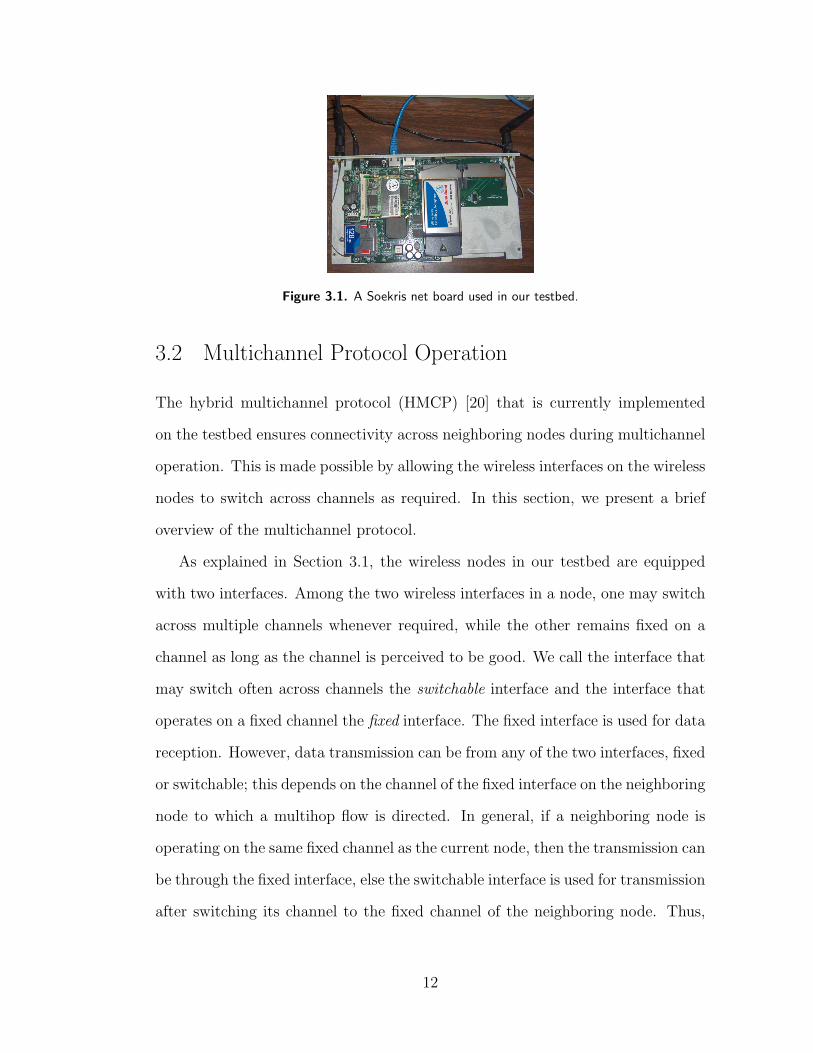
Figure 3.1. A Soekris net board used in our testbed.
3.2 Multichannel Protocol Operation
The hybrid multichannel protocol (HMCP) [20] that is currently implemented
on the testbed ensures connectivity across neighboring nodes during multichannel
operation. This is made possible by allowing the wireless interfaces on the wireless
nodes to switch across channels as required. In this section, we present a brief
overview of the multichannel protocol.
As explained in Section 3.1, the wireless nodes in our testbed are equipped
with two interfaces. Among the two wireless interfaces in a node, one may switch
across multiple channels whenever required, while the other remains fixed on a
channel as long as the channel is perceived to be good. We call the interface that
may switch often across channels the switchable interface and the interface that
operates on a fixed channel the fixed interface. The fixed interface is used for data
reception. However, data transmission can be from any of the two interfaces, fixed
or switchable; this depends on the channel of the fixed interface on the neighboring
node to which a multihop flow is directed. In general, if a neighboring node is
operating on the same fixed channel as the current node, then the transmission can
be through the fixed interface, else the switchable interface is used for transmission
after switching its channel to the fixed channel of the neighboring node. Thus,
12
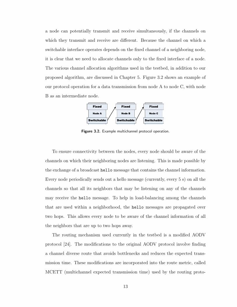
a node can potentially transmit and receive simultaneously, if the channels on
which they transmit and receive are different. Because the channel on which a
switchable interface operates depends on the fixed channel of a neighboring node,
it is clear that we need to allocate channels only to the fixed interface of a node.
The various channel allocation algorithms used in the testbed, in addition to our
proposed algorithm, are discussed in Chapter 5. Figure 3.2 shows an example of
our protocol operation for a data transmission from node A to node C, with node
B as an intermediate node.
Figure 3.2. Example multichannel protocol operation.
To ensure connectivity between the nodes, every node should be aware of the
channels on which their neighboring nodes are listening. This is made possible by
the exchange of a broadcast hello message that contains the channel information.
Every node periodically sends out a hello message (currently, every 5 s) on all the
channels so that all its neighbors that may be listening on any of the channels
may receive the hello message. To help in load-balancing among the channels
that are used within a neighborhood, the hello messages are propagated over
two hops. This allows every node to be aware of the channel information of all
the neighbors that are up to two hops away.
The routing mechanism used currently in the testbed is a modified AODV
protocol [24]. The modifications to the original AODV protocol involve finding
a channel diverse route that avoids bottlenecks and reduces the expected trans-
mission time. These modifications are incorporated into the route metric, called
MCETT (multichannel expected transmission time) used by the routing proto-
13
col [20].
More details on the multichannel protocols can be found in [25] and [26], and
also at http://www.crhc.uiuc.edu/wireless/netx.html.
3.3 System Architecture
In this section, we briefly describe the major aspects of the system architecture.
Details are available in [25] and [26].
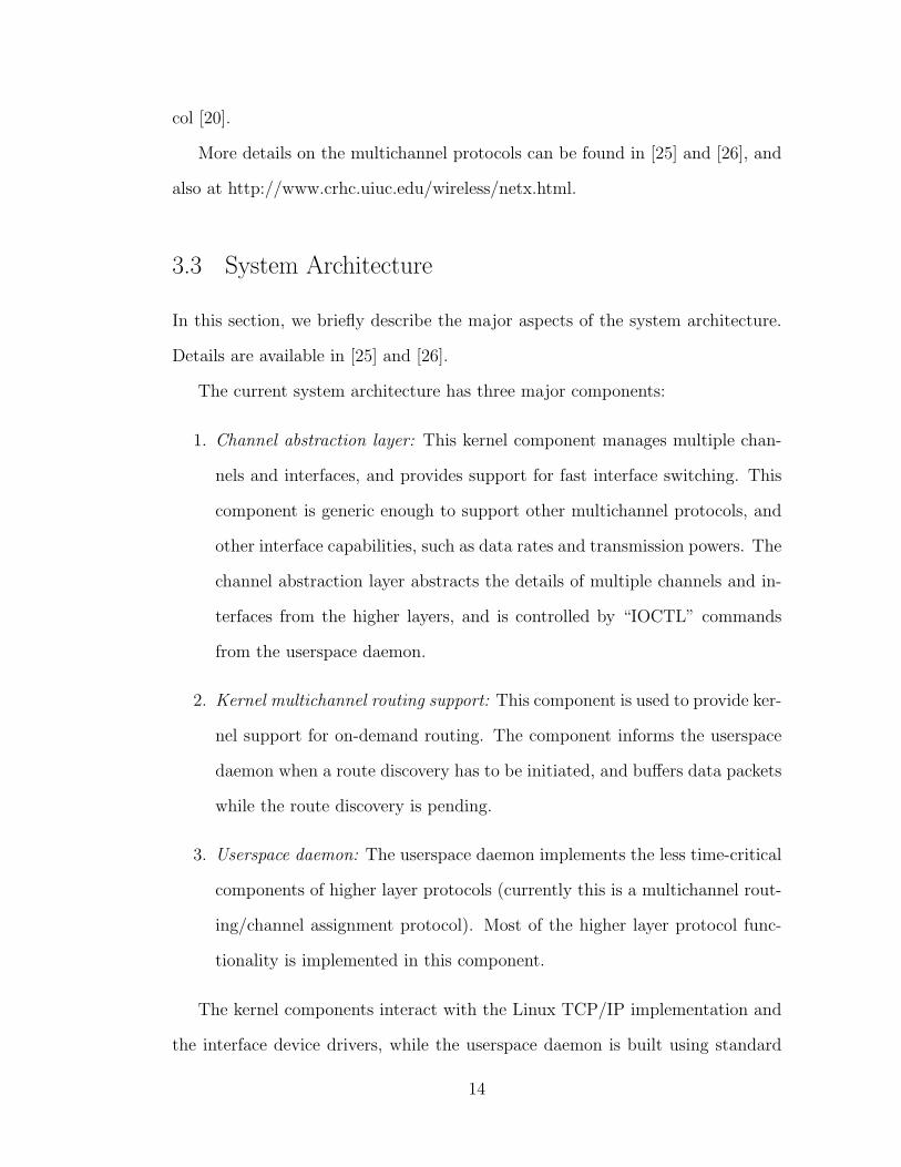
The current system architecture has three major components:
1. Channel abstraction layer: This kernel component manages multiple chan-
nels and interfaces, and provides support for fast interface switching. This
component is generic enough to support other multichannel protocols, and
other interface capabilities, such as data rates and transmission powers. The
channel abstraction layer abstracts the details of multiple channels and in-
terfaces from the higher layers, and is controlled by “IOCTL” commands
from the userspace daemon.
2. Kernel multichannel routing support: This component is used to provide ker-
nel support for on-demand routing. The component informs the userspace
daemon when a route discovery has to be initiated, and buffers data packets
while the route discovery is pending.
3. Userspace daemon: The userspace daemon implements the less time-critical
components of higher layer protocols (currently this is a multichannel rout-
ing/channel assignment protocol). Most of the higher layer protocol func-
tionality is implemented in this component.
The kernel components interact with the Linux TCP/IP implementation and
the interface device drivers, while the userspace daemon is built using standard
14
userspace networking libraries.
3.3.1 Channel abstraction layer
The channel abstraction layer (CAL) is implemented as a part of the bonding
driver present in the Linux kernel. Its key components include:
1. Unicast component: Enables specifying the channel to use to reach a neigh-
bor.
2. Broadcast component: Provides support for sending broadcast packets over
multiple channels.
3. Scheduling and queuing component: Supports interface switching by buffer-
ing packets when necessary, and scheduling switching across channels.
In addition, the madwifi driver for Atheros-based NICs (which are used by our
wireless nodes) has been modified to better support channel switching.
15

CHAPTER 4
INTERFERENCE EFFECTS
Adjacent channel interference effects are usual in technologies such as IEEE
802.11b/g due to channel overlaps. (IEEE 802.11b/g has 11 channels of which only
three are nonoverlapping, namely channels 1, 6, and 11.) IEEE 802.11a, on the
other hand, is considered to be free of such effects because all the 12 channels are
nonoverlapping. However, this is not the case in practice as we will show through
experiments later in this chapter. One reason for this could be due to power
regulations imposed by the government, which result in a nonuniform power out-
put by each of the channels. For instance, Table 4.1 tabulates the list of 802.11a
channels allowed in the United States, and the maximum power restrictions on
the channels imposed by the FCC. In addition, as discussed in Chapter 1, the
adjacent channel interference effects are also due to improper filter characteristics
and poor signal processing at the wireless cards. We illustrate this fact using the
following experiment conducted using a spectrum analyzer.
4.1 Spectrum Analyzer-Based Experiments
For this experiment, we use a single net4521 board. We generate UDP traffic
(using a socket program) through a PCMCIA card in broadcast mode at a fixed
rate of 6 Mbps. We used a BumbleBee YellowjacketTM spectrum analyzer man-
ufactured by Berkeley Varitronics Systems R© to measure the power output from
the wireless card. Figure 4.1 shows the spectrum analyzer output for the traffic
16

Table 4.1. IEEE 802.11a channels and maximum power restrictions allowed by the FCC in the U.S.
BANDCHANNEL FREQUENCY MAXIMUMNUMBERS (MHz) OUTPUT POWER
U-NII Lower band
36 518040 5200 40 mW44 5220 (2.5 mW/MHz)48 5240
U-NII Middle band
52 526056 5280 200 mW60 5300 (12.5 mW/MHz)64 5320
U-NII Upper band
149 5745153 5765 800 mW157 5785 (50 mW/MHz)161 5805
generated on various channels. As shown by the figure, we could observe that
the power output for the boundary frequencies (such as 36, 64, 149, and 161)
is at least 10 dB lower than the power output for channels in the middle of the
spectrum, such as 44 and 52. In particular, the power for the border frequencies
was around -50 dBm while that of channels 44 and 52 was found to be around -40
dBm. We repeated the same experiment by generating the UDP traffic from the
mini-PCI card, and the results are shown in Figure 4.2. In this case, the transmis-
sion power on channels 36, 44, and 52 was around -40 dBm and that on channels
60, 64, 149, and 161 was 10 dB lower at around -50 dBm. As a consequence of this
nonuniform power output by different channels, a transmission on a channel with
a strong power output might affect a simultaneous reception in its neighborhood
that was on an adjacent channel transmitted with less power. Furthermore, the
difference in power can also affect a simultaneous reception on a weaker channel
on one radio due to a transmission on a stronger channel by an adjacent radio
within a wireless node. This leads to irregular interference characteristics across
the channels, which we illustrate using the following experiments.
17

Figure 4.1. Spectrum analyzer plots for PCMCIAcard for channels (from left to right and top tobottom) 36, 44, 52, 60, 64, 149, and 161.
Figure 4.2. Spectrum analyzer plots for mini-PCIcard for channels (from left to right and top tobottom) 36, 44, 52, 60, 64, 149, and 161.
4.2 Interference Effects in a Network
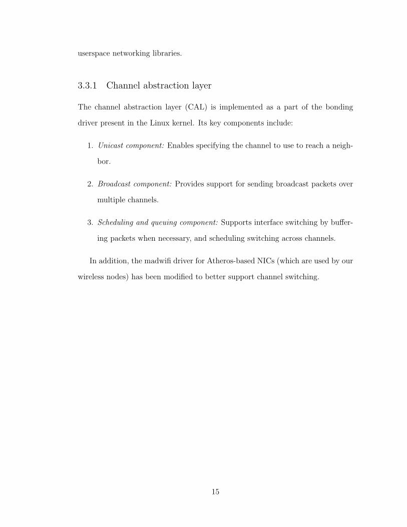
The IEEE 802.11a standard [27] specifies a clear channel assessment (CCA)
scheme, in which nodes assess whether the channel is busy or not before attempt-
ing a transmission. If a wireless node can decode the start of an OFDM symbol
transmission (namely, preamble) at a receive level equal to or greater than the
minimum modulation and coding rate sensitivity of -82 dBm (for a 20 MHz chan-
nel spacing as used in our testbed), then the channel is detected as busy with a
90% probability. If the preamble was missed, then the channel can be termed busy
if the node can receive a transmission at a power level 20 dB above the minimum
modulation and coding rate sensitivity (which is -62 dBm for a 20 MHz channel
spacing). Figure 4.3 illustrates the CCA mechanism pictorially. The authors in [3]
have claimed that an adjacent channel transmission can trigger a false negative
during CCA, thereby leading to collisions. In other words, an adjacent channel
transmission cannot be detected by 802.11’s CCA mechanism. We demonstrate
this using the following set of experiments.
18
Figure 4.3. IEEE 802.11a clear channel assessment scheme.
The main objectives of our experiments are to illustrate the following:
• Cochannel and adjacent channel interference effects in a network
• Number of hops over which the interference can exist.
The term ‘hop’ in the above statement can be explained as follows. If two nodes
have a direct communication link between them, then they are said to be within
one hop from each other. If a transmission from one node to another requires
k one-hop transmissions, then the nodes are said to be k hops away from each
other.
We have performed the experiments on our Net-X testbed and we show a
snapshot (of the experiment in action), as viewed by a visualization tool developed
by our group, for each of the experiments.
4.2.1 Cochannel and adjacent channel interference effects
For this experiment, we use four nodes such that every node is a one-hop neighbor
to every other node. The network topology is shown in Figure 4.4, and Figure 4.5
shows a snapshot of our topology on the visualization tool. In Figure 4.5, the
circles represent wireless nodes and their colors indicate the channels on which
the nodes receive traffic. Furthermore, the solid lines indicate the presence of a
19

Figure 4.4. Four-node network topology used forinterference experiments.
Figure 4.5. Four-node network topology from thevisualization tool.
wireless link, and the arrows indicate the direction of a link. Thus, solid line with
arrows on both the ends indicate a bi-directional link. The dotted arrows indicate
a traffic flow and the direction of the flow.
In this experiment, we first generate four unicast UDP flows at a rate of 6
Mbps in the form of a ring as shown in Figure 4.4, such that every node is a
source and destination of exactly one flow. We used the iperf utility, available in
Linux, for generating the UDP traffic between the nodes. The transmission rate
of the wireless cards is fixed at 6 Mbps. The UDP traffic is sent for a duration
of 50 s. To capture the effect of interference due to simultaneous transmissions
by the two radios in the same node, we vary the channel separation between the
transmissions from 0 to 3 and measure the total throughput achieved by the four
nodes for each channel separation. For example, with a channel separation of 2,
the link AB uses channel 36, link BC uses channel 44 (two channels apart from
channel 36), link CD uses channel 52, and link DA uses channel 60. For a channel
separation of 3, the link DA uses channel 149, while the links AB, BC, and CD
use 36, 48, and 60, respectively.
20

Figure 4.6. Throughput results for four flows in the form of ring.
Figure 4.6 shows the measured throughput values for each of the channel sepa-
rations averaged over 30 runs. We observe from the plot that the total throughput
increases as we increase the channel separation between the transmissions. Fur-
thermore, we observe that the performance when all the nodes are operated on the
same channel is worse than the case where the receive and transmit channels are
separated by at least one channel. Finally, we observe that there is no throughput
loss when the traffic is on channels separated by three.
Next, to illustrate the interference effects due to transmissions from a neigh-
boring node, we generate two 6 Mbps unicast UDP flows for 50 s, using the
four-node topology shown in Figures 4.7 and 4.8. We generate one flow from node
A to node D, and the other from node C to node B so that there are a data
transmission and a reception adjacent to each other. We then vary the channel
separation between the two transmissions from 0 to 3, as before, and measure
the total throughput achieved by the two transmissions. The throughput values
averaged over 30 runs are shown in Figure 4.9. We observe from the plot that the
trend is similar to the one observed in the previous case - the throughput improves
with increasing separation between the transmission channels. Furthermore, there
21

is no significant throughput loss when the transmissions are on channels separated
by two. This shows that the interference effects diminish as the distance between
two interfering transmissions increases.
Figure 4.7. Four-node network topology showingtwo adjacent flows.
Figure 4.8. Four-node network with two flowsfrom the visualization tool.
Figure 4.9. Throughput results for two adjacent flows.
22

Figure 4.10. Linear network topology used forinterference experiments.
Figure 4.11. Linear network topology from thevisualization tool.
4.2.2 Number of hops over which interference exists
The two experiments described above show that the interference in wireless net-
works can be attributed to a simultaneous transmission and reception on the same
channel or on adjacent channels. Furthermore, the interference can be caused ei-
ther by a simultaneous transmission within the same node or by a transmission
from a neighboring node. In the next experiment we show that interference can
also be attributed to a transmission by a two-hop neighbor. For this purpose, we
use a linear topology as shown in Figure 4.10. Figure 4.11 shows the correspond-
ing topology as seen by the visualization tool. We once again generate two 6 Mbps
UDP flows, one from node A to node B and the other from node C to node D,
so that A’s transmission is two hops away from node D. We fix the channel on
which A sends to B, and vary the channel in which C transmits to D. We have
plotted the corresponding throughput at node D in Figure 4.12. We observe that
throughput at node D is poor when node A’s transmission is on the same channel
over which D receives traffic from C. This suggests that even a two-hop neighbor
can create sufficient interference. Additionally, we also observe that there is no
23

significant interference when the channels of the two transmissions are separated
by at least one channel.
Figure 4.12. Throughput results for the linear network.
We summarize the observations from our experiments below. For each obser-
vation, we also list the approach for reducing the interference in the network.
1. Observation: A simultaneous transmission and reception in a wireless node
can interfere with each other if they are on channels separated by fewer than
three.
Approach: No two interfaces on the same wireless node should operate
(transmit or receive) simultaneously on channels that are separated by two
or lower. In our system, the channel on which a wireless node transmits
depends on the receive channel of a neighboring node. We therefore require
that all the one-hop neighbors are allocated channels that are spectrally
farther than two from the receive channel of a node.
2. Observation: Interference can also be due to transmission by a neighboring
node, which is on a channel that is fewer than two channels away.
24

Approach: None of the one-hop neighbors of a node should transmit on the
same or an immediately adjacent channel. Again, based on the fact that the
channel on which a one-hop node transmits depends on the receive channel
of its immediate neighbors, we reduce the posibility of two-hop neighbors of
a node being allocated the same or an adjacent channel as the one allocated
to the node under consideration.
3. Observation: A reception and a transmission on the same channel can in-
terfere if they are within three hops of each other.
Approach: None of the two-hop neighbors of a node should transmit on the
same channel as the receive channel of the node under consideration. We
therefore require that no two nodes that are three hops from each other
receive on the same channel. However, this may not be feasible as this may
incur a large overhead for propagating the channel information of a node
over three-hops. We therefore will not be considering this approach while
formulating our channel allocation problem.
The experiments in this chapter motivate the need for an efficient channel
allocation algorithm that adopts the approaches listed above while making use
of as many channels as possible. However, as we will show later in this thesis, a
completely greedy algorithm that strictly adheres to approaches listed above will
be suboptimal. We propose an efficient algorithm that attempts to minimize the
interference in the network so as to improve the overall network throughput.
25

CHAPTER 5
CHANNEL ALLOCATION ALGORITHM
5.1 Channel Assignment Problem Formulation
We now formulate the channel allocation algorithm based on our experimental
results.
5.1.1 Network and interference model
We consider a multihop wireless network with static routers. Each router node
is equipped with m wireless interfaces. A subset of the interfaces, ms, in a node
may switch across channels frequently. The remaining interfaces, mf = (m −
ms), typically operate on a fixed channel and so do not switch their channels
as frequently as do the switchable interfaces (or they switch their channel at a
relatively much longer time scale when compared to the switchable interface).
Note that the switchable interfaces ensure connectivity to all the neighboring
nodes. The channel allocation algorithm that we present here is used for allocating
channels to the fixed interfaces. A link (i, j) exists between two nodes i and j
if they are within the communication range of each other and have a switchable
interface that can be tuned to one of each other’s fixed channels. If a link exists
between two nodes i and j, then j is a one-hop neighbor of node i and vice
versa. We therefore have an implicit assumption that the links are bidirectional.
Furthermore, the one-hop neighbors of j that are not the one-hop neighbors of i
26

are said to be the two-hop neighbors of i, and so on. We assume that any pair
of nodes have only one link between them irrespective of the number of fixed or
switchable interfaces between them.
We have the following constraint for channel allocation:
Interference constraint
From our experiments we can observe that channels separated by two or less in a
spectrum should not be allocated to a one-hop neighbor and channels separated
by one or less should not be allocated to a two-hop neighbor. In other words, if
one of the fixed interfaces of a node, v, is allocated a channel c, then the channels
c + 1, c − 1, c + 2 or c − 2 should not be allocated to any of the fixed interfaces
of a one-hop neighbor, and channels c + 1 and c − 1 should not be allocated to
a two-hop neighbor. These are the constraints that need to be satisfied by our
channel allocation algorithm.
The objective of our channel allocation algorithm is as follows:
Load balancing
The goal of our channel allocation algorithm is to minimize the number of nodes
that are allocated the same channel to any of their fixed interfaces within a two-
hop neighborhood, while meeting the interference constraints. In other words, our
objective is to locally balance the channel usage within a two-hop neighborhood.
In the next sections, we discuss a simple algorithm for solving the channel
allocation problem. We show that this algorithm is not effective in reducing the
interference effects in the network. We then discuss our proposed traffic-aware
algorithm that performs better. We use the overall network throughput as a
metric for comparing the performance of the channel allocation algorithms.
27

5.2 A Simple Load Balancing Channel Allocation
Algorithm
In this section, we first discuss a simple load-balancing channel allocation algo-
rithm proposed by Kyasanur and Vaidya in [20]. This algorithm avoids adjacent
channel interference effects by making use of only 5 out of 12 channels, namely
channels 36, 48,64, 149, and 161. The algorithm is as follows:
LoadBal:
input: chanList, neighList, switchProb
At every node n,
currChan← chanList[1]
for i in chanList
chanCount[i]← 0
for neigh in neighList
chanCount[channel(neigh)]++
if(chanCount[currChan] ≥ mean(chanCount) + 1) AND
(chanCount[currChan] > min(chanCount) + 1)
With probability p
currChan← minChan
return currChan
According to this algorithm, every node has access to a chanList, which is
the channel information of all of its neighbors in the neighList. The neighList
contains the list of neighbors of a node within its two hops. The nodes obtain
the channel information by periodically broadcasting a hello message (every 5
s), which is propagated over two hops. Every node evaluates the load on each
channel by counting the number of two-hop neighbors using the channel. A node
then probabilistically decides to switch its channel if the load on the current
channel is greater than the average load, returned by meanchanCount. The current
28

channel is switched to a channel that has the minimum load, namely minChan.
The minimum channel count is obtained using the function minchanCount in the
above algorithm. A node decides to switch to minChan only when the load on
the current channel is one more than the load on the minChan.
Note that this simple load balancing algorithm satisfies all the three essential
properties of a good channel allocation algorithm mentioned in Chapter 1. Specif-
ically, load balancing is achieved by locally balancing the channel utilization over
a two-hop neighborhood. Adjacent channel interference is avoided by making use
of only a subset of channels, and only the channel information for nodes within
a two-hop neighborhood is required for this algorithm. Because only 5 out of
12 channels are used for allocation, more than 50% of the channels are left un-
used. Therefore, this algorithm does not make use of the spatial resuse (i.e., the
number of concurrent interference-free transmissions in the network) that can be
potentially achieved by using all of the channels.
5.2.1 Improved simple load-balancing algorithm
We now show that we can improve the performance of this algorithm by using all
the channels instead of just a subset of channels. For this purpose, we conduct an
experiment on a network of 10 nodes. The topology used for this experiment is
shown in Figure 5.1. Figure 5.2 shows the topology as viewed using our visualiza-
tion tool. We generate ten 6 Mbps one-hop, unicast UDP flows in a ring fashion
similar to the first experiment discussed in Chapter 4, so that every node is both
a source and destination of one flow. We compare the overall network throughput
(sum of individual throughputs of all 10 flows) achieved using the simple load
balancing allocation algorithm with just five channels with that of the same algo-
rithm using 8, 10, and 12 channels. Note that the five channels used for allocation
29

are noncontiguous, namely 36, 48, 64, 149, and 161, while the case where we use
8, 10, and 12 uses contiguous channels. Thus, for the 8-channel case we use all
eight channels in the lower and middle UNII bands; for the 10-channel case we
use the two channels in the upper UNII band in addition to the eight channels in
the lower and middle UNII bands; and the 12-channel case uses all the channels
allowed in 802.11a.
Figure 5.1. A 10-node network topology used forcomparing the load balancing algorithms.
Figure 5.2. A 10-node network from the visual-ization tool.
Figure 5.3 shows the comparison plots of the network throughputs averaged
over 25 runs. We use the auto rate functionality of 802.11 for selecting the trans-
mission rates of the wireless cards. From the plots, we observe that the perfor-
mance for the case where we use just 5 channels is worse than the case where
we use 8, 10 or 12 contiguous channels. Furthermore, the throughput achieved is
highest when we use all 12 channels. This is because, when we use more channels,
the number of simultaneous transmissions in the network can increase, which is
a consequence of the physical carrier sensing mechanism in 802.11a (discussed in
Section 4.2). Therefore, the overall throughput in the network increases with the
number of channels.
Note that this version of the simple algorithm can still achieve a load-balanced
channel allocation with a minimal information exchange between the nodes. How-
ever, this algorithm does not consider the interference effects. We wish to explore
30

Figure 5.3. Throughput comparison between the simple load balancing algorithm using a subsetcontaining five channels and that using more contiguous channels.
whether a further improvement in throughput can be achieved if interference ef-
fects are factored into the algorithm. Our traffic-aware algorithm discussed in the
next section addresses this point.
5.3 Traffic-Aware Channel Allocation Algorithm
The simple load balancing algorithm is capable of achieving a significant im-
provement in the network throughput by using all the available channels in spite
of interference due to adjacent channel transmissions. This suggests that we can
allocate channels to the nodes less conservatively based on the simple load balanc-
ing algorithm using all channels and decide on changing the channel allocation
dynamically based on the traffic conditions in the network. Our traffic-aware
channel allocation algorithm exploits this reasoning.
The traffic-aware algorithm is executed in two phases as follows:
1. The first phase allocates the channels to the nodes using the simple load
balancing channel allocation algorithm with all the channels as described in
Section 5.2.1.
31

2. During the second phase, when the switchable interface is transmitting data
on a channel that is within two channels from that allocated to the fixed
interface, the channel of the fixed interface is switched to a channel that is
farther than two from the channel used by the switchable interface.
Because the first phase of the algorithm is based on the earlier simple al-
gorithm, the load balancing property is satisfied. Furthermore, no additional
messages other than the two-hop channel information are exchanged between the
nodes. Finally, the second phase of the algorithm reduces the interference due to
simultaneous adjacent channel activity within a node. However, for reducing the
interference due to adjacent channel transmissions by a neighboring node, we may
need to communicate the traffic information between the nodes in addition to the
channel usage. This may introduce additional overhead in the network. Instead,
we propose the following channel selection mechanism:
Channel selection mechanism
Whenever a node needs to choose a channel, choose the channel that is spectrally
farthest from the channels that are already allocated to its neighbors, in addition
to maintaining the load balance across channels. The spectrally farthest channel
is chosen even if the node decides to switch to another channel for the purposes
of load balancing or interference avoidance. To determine the spectrally farthest
channel, we use the following distance factor:
distancei =∑
j∈neighChannels,j 6=i
1
|i− j|∀i ∈ K (5.1)
where K is the set of all channels available for allocation, and neighChannels
is the set of channels assigned to the neighbors of a node. We now present our
traffic-aware channel allocation and the channel selection algorithm.
32
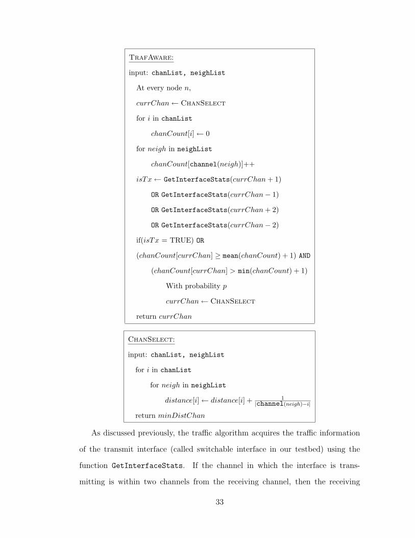
TrafAware:
input: chanList, neighList
At every node n,
currChan← ChanSelect
for i in chanList
chanCount[i]← 0
for neigh in neighList
chanCount[channel(neigh)]++
isTx← GetInterfaceStats(currChan + 1)
OR GetInterfaceStats(currChan− 1)
OR GetInterfaceStats(currChan + 2)
OR GetInterfaceStats(currChan− 2)
if(isTx = TRUE) OR
(chanCount[currChan] ≥ mean(chanCount) + 1) AND
(chanCount[currChan] > min(chanCount) + 1)
With probability p
currChan← ChanSelect
return currChan
ChanSelect:
input: chanList, neighList
for i in chanList
for neigh in neighList
distance[i]← distance[i] + 1|channel(neigh)−i|
return minDistChan
As discussed previously, the traffic algorithm acquires the traffic information
of the transmit interface (called switchable interface in our testbed) using the
function GetInterfaceStats. If the channel in which the interface is trans-
mitting is within two channels from the receiving channel, then the receiving
33

channel is switched to a different channel (with a probability p) as chosen by
the ChannelSelect algorithm. The receive channel may also be changed to
a different channel if the number of nodes operating on the current channel
is more than the average utilization, similar to the LoadBal algorithm. The
ChannelSelect algorithm chooses the channel, minDistChan, that has the
minimum value for the metric in Equation (5.1).
34

CHAPTER 6
IMPLEMENTATION DETAILS
Before proceeding to the performance evaluation of our algorithm, we discuss a
few implementation-specific details of our algorithm.
6.1 User Space Entity
Our algorithm is implemented purely in the user space and does not require any
changes to be made to the kernel or the wireless drivers. The channel allocation
algorithm relies on the exchange of broadcast hello messages within a two-hop
neighborhood. As mentioned in Chapter 3, the hello messages contain the receive
channel information of all the two-hop neighbors of a node. Every node calculates
the utilization of the channels by counting the number of nodes on each channel
using the hello messages. The nodes then pick a channel so as to balance the
utilization on all of the channels as described in Chapter 5.
The function that implements our traffic-aware channel allocation algorithm
is named InterferenceAwarePolicyCheckForChannelSwitch(). This function
returns a Boolean value indicating whether or not to change the current receive
channel. The decision to change the current channel is based on the instantaneous
traffic activity of a node. If a node transmits on a channel that is adjacent to the
receive channel, then the algorithm will decide to change the receive channel. The
traffic information is obtained from the channel abstraction module as explained
in the next section.
35

In addition to calculating the utilization of each of the channels, our algorithm
also calculates a distance factor between the channels. This is computed based
on the inverse of the relative spectral separation between the channels that are
currently used in the two-hop neighborhood. The channel selection algorithm then
chooses a channel that has the least distance factor. The details of the distance
factor and the channel selection algorithm were explained in Chapter 5.
6.2 Interaction with the Kernel Space
The traffic information required by our channel allocation algorithm is obtained
from the channel abstraction module described in [25] and [26]. The channel
abstraction module is implemented as a kernel module and is responsible for
abstracting the multiple interface capabilities from the lower layers. In addition
to this, the module maintains a per-channel queue for each of the interfaces, and
assists in routing by evaluating the route metric. Additionally, the module also
maintains the statistics such as the channel usage, the current channel used by the
transmit interface, number of packets and bytes transmitted, and the number of
switches performed by the transmit interface. The traffic information on each of
the channels is one of the sets of statistical information computed by the channel
abstraction module. Because we need to communicate with a kernel module from
a user-space program, we made use of a private IOCTL (input-output control)
call, namely, Ioctl GetSwitchingStats() to the kernel module from the user-
space program. The traffic information is obtained in the form of the estimated
transmission time (ETT), which gives an estimate of the time taken by the packets
to get transmitted. The ETT is given by the following expression:
ETT = ETX ∗ S
B
36

where ETX is the expected number of transmission attempts (including re-
transmissions) required to transmit a packet, S is the average packet size and
B is the data rate of the link. The expected number of transmissions is estimated
based on the loss in the link.
Whenever the channel allocation algorithm is executed, the algorithm sends an
IOCTL query to the channel abstraction module requesting the ETT information.
The algorithm then checks if the ETT value of the channels adjacent to the current
receive channel is above a certain threshold. If it is, then the algorithm searches
for a lightly loaded channel that is spectrally farther from the other neighboring
channels and switches to that channel. The channel is not switched if the ETT
value is above the threshold in the current channel or in a channel other than the
neighboring channels. The system architecture, with the blocks relevant to our
channel allocation algorithm highlighted, is shown in Figure 6.1.
Figure 6.1. Net-X system architecture with the block containing the channel allocation protocolhighlighted.
6.3 Invoking the Traffic-Aware Algorithm
The channel allocation algorithm requires a channel-list file containing the list
of channels that are available for allocation. The traffic-aware algorithm can be
37

invoked by including a string Interference-Aware <channel> in the channel-
list file. If we prefer a particular initial channel for a node, then we can mention
that by substituting the <channel> parameter with the preferred 802.11a channel
number. This may be useful for testing - to check if the initial channel affects the
channel switching decision of the algorithm. If we do not prefer any particular
channel to begin with, then the <channel> parameter can be set as 0. In this
case, all the nodes will start on the first channel mentioned in the channel-list file.
38

CHAPTER 7
PERFORMANCE RESULTS
In this section, we discuss a set of experiments to illustrate the performance
benefits of our algorithm. As before, we use the overall network throughput
as the main performance metric for evaluating our algorithm. We compare the
throughput obtained using our algorithm with that obtained using the simple load-
balancing algorithm that uses all 12 channels, and also with that obtained using
a channel allocation that is estimated to be “optimal” as described below. The
optimal channel allocation is obtained by trying out many possible combinations of
channel allocations to the nodes. Because the number of combinations of channel
allocations is large, we tried out only those allocations that allocate nonadjacent
channels to a one-hop neighbor. In other words, having allocated a channel, say,
c, to a node, we ignore allocations that allocate channel (c + 1) or (c − 1) to
any of the one-hop neighbors of this node. For every allocation we average the
overall throughput over 30 runs. We then choose the allocation that resulted in
the maximum overall throughput as the “optimal” allocation. We conducted two
sets of experiments. In the first set of experiments, we had two flows at each node
and in the second set of experiments, each node was involved in only one flow.
We discuss the experimental setup and the results in detail.
39

Table 7.1. Throughput (in Mbps) comparison between the load-balancing and traffic-aware algo-rithms - two flows at each node.
Contiguous Load-Balancing Traffic-Aware Percentage OptimalChannels Algorithm Algorithm Improvement Throughput
4 16.79 19.31 14.96% 20.746 26.11 30.57 17.10% 30.868 38.18 44.84 17.42% 46.2210 39.82 46.43 16.59% 47.8012 43.76 49.71 13.61% 50.32
7.1 Two Flows at Each Node
We use the 10-node network topology discussed in Section 5.2.1, shown in Fig-
ure 5.1, for evaluating our algorithm. As shown in the figure, we generate ten 6
Mbps UDP flows in a ring fashion so that every node is both a source and a des-
tination of one UDP flow. This ensures that both the radios are active in a node.
We then allocate channels using the simple load-balancing algorithm first, and
then our traffic-aware algorithm, and we measure the overall network through-
put, which is the sum of the throughputs achieved by each of the nodes. We vary
the number of contiguous channels available for allocation from 4 to 12. Thus,
when the number of channels available is four, we use channels 40, 44, 48, and
52. Similarly, for the case of eight channels, we use channels 36 through 64, all in
the lower and middle UNII bands. Furthermore, for 12 channels we use all twelve
802.11a channels allowed in the U.S. The measured throughput values, averaged
over 25 runs, are shown in Figure 7.1. The transmission rate of the wireless cards
is determined based on the auto-rate functionality built in their drivers. Figure 7.1
also shows the optimal throughput obtained with each number of channels. We
have also plotted the 95% confidence interval bars for our throughput values. Ta-
ble 7.1 tabulates the throughput values and the percentage improvement of the
traffic-aware algorithm over the simple load-balancing algorithm.
40

Figure 7.1. Comparison between the load-balancing and traffic-aware algorithms - two flows at eachnode.
From our figure, we first observe that the throughput achieved by our traffic-
aware algorithm is close to the optimal throughput. Additionally, we observe
from the plots that the throughput obtained using our traffic-aware algorithm is
significantly better than that obtained using the simple load-balancing algorithm.
Specifically, we note from Table 7.1 that a throughput improvement of up to 17.4%
(corresponding to eight channels) can be obtained using our algorithm. However,
we also observe that the throughput improvement obtained using our algorithm
diminishes when we have fewer channels to allocate. In particular, when we use
four channels, the throughput improvement decreases to 14.9%. This may be
due to adjacent channel interference from the neighboring nodes, which cannot
be fully avoided due to the close proximity of the nodes and the limited number
of channels. However, the improvement in throughput obtained using our algo-
rithm is still substantial. Additionally, we can also observe that the throughput
improvement from our algorithm is reduced when we have a large number of chan-
nels. For instance, from Table 7.1, we observe that the throughput corresponding
to the case of 12 channels is 13.61%. The reason for this is that, when we have
more channels to allocate, even a load-balancing algorithm can achieve a channel
allocation such that the neighboring transmissions are on channels that are more
41

likely to be well-separated, which is good enough to reduce the interference in
the network. However, as we can observe from the confidence interval bars, the
variation in the throughput values is often higher for the load-balancing algorithm
when compared to our trafic-aware algorithm. Moreover, the lower end of the con-
fidence interval bar of the traffic-aware algorithm is typically above the average
throughput value achieved using the load-balancing algorithm.
We will now show that our algorithm can provide good performance improve-
ments even for TCP flows. To demonstrate this, we use the same 10-node network
topology as above and generate TCP flows using the iperf utility for 100 s. We,
once again, use the autorate functionality of 802.11a to control the transmis-
sion rate. The overall network throughput as achieved by our algorithm and
that achieved using the load-balancing algorithm are shown in Figure 7.2, and
the throughput values are tabulated in Table 7.2. As we can observe from the
figure and the table, the throughput achieved by our algorithm is better than
that achieved by the load-balancing algorithm. Because a traffic-aware allocation
decreases the interference in the network, the number of collisions and retrans-
missions are reduced, which helps improve the performance of TCP flows.
Figure 7.2. Comparison between the load-balancing and traffic-aware algorithms for TCP flows.
42

Table 7.2. Throughput (in Mbps) comparison between the load-balancing and traffic-aware algo-rithms for TCP flows.
Contiguous Load-Balancing Traffic-Aware Percentage OptimalChannels Algorithm Algorithm Improvement Throughput
4 26.63 28.35 6.47% 29.196 26.68 29.16 9.29% 29.198 31.28 33.82 8.12% 34.2010 33.23 36.81 10.79% 37.1512 32.94 35.68 8.34% 36.99
7.2 One Flow at Each Node
Figure 7.3. A 10-node network topology with one flow at each node.
In this set of experiments, we show that the traffic-aware algorithm can achieve
a good performance improvement over the load-balancing algorithm when every
node is involved in only one transmission. Note that, in this case, because there
are no simultaneous receptions and transmissions in a node, the traffic awareness
component of our algorithm is not beneficial. The improvement achieved is purely
due to the channel selection mechanism used by our algorithm. For this experi-
ment, we generate one-hop UDP flows at a rate of 6 Mbps from each node to one
of its immediate neighbors in a 10-node network as shown in Figure 7.3. We then
measure the total network throughput achieved and plot the values after aver-
aging them over 25 runs. Figure 7.4 shows the corresponding throughput values
along with the 95% confidence intervals, and Table 7.3 tabulates the throughput
43

Figure 7.4. Comparison between the load-balancing and traffic-aware algorithms - only one flow ateach node.
Table 7.3. Throughput (in Mbps) comparison between the load-balancing and traffic-aware algo-rithms - only one flow at each node.
Contiguous Load-Balancing Traffic-Aware PercentageChannels Algorithm Algorithm Improvement
4 20.81 21.03 1.10%6 24.86 27.05 8.80%8 27.95 29.88 6.90%10 26.90 30.02 11.59%12 26.74 29.75 11.23%
values.
From the figure and the table, we observe that the improvement in throughput
using the traffic-aware algorithm over the load-balancing algorithm increases as
the number of channels available for allocation increases. This is because, when
we have more channels to allocate, the channel selection algorithm can choose
channels that are farther apart, thereby reducing the interference. This will not
be possible when we have very few channels to allocate, as observed in the case of
four channels. Further improvement in throughput is possible if traffic information
can be exchanged across nodes. However, this might incur additional overhead in
the network.
The trend is similar in the case of TCP flows as observed in Figure 7.5 and
44
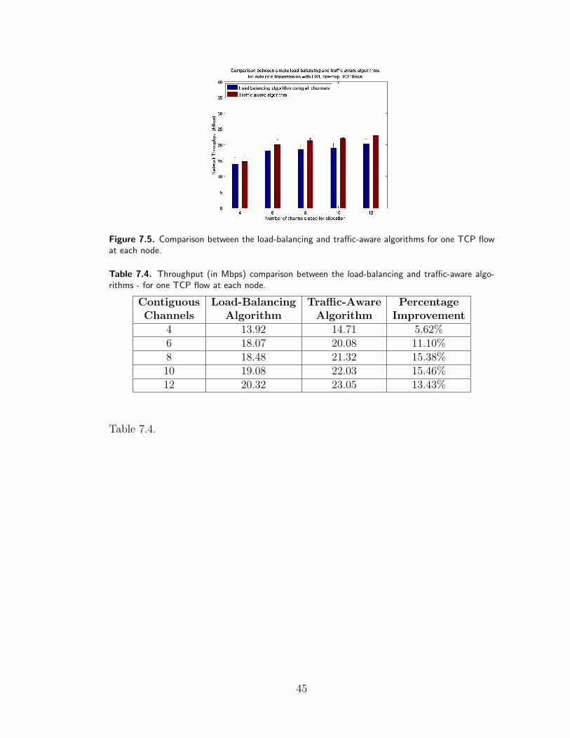
Figure 7.5. Comparison between the load-balancing and traffic-aware algorithms for one TCP flowat each node.
Table 7.4. Throughput (in Mbps) comparison between the load-balancing and traffic-aware algo-rithms - for one TCP flow at each node.
Contiguous Load-Balancing Traffic-Aware PercentageChannels Algorithm Algorithm Improvement
4 13.92 14.71 5.62%6 18.07 20.08 11.10%8 18.48 21.32 15.38%10 19.08 22.03 15.46%12 20.32 23.05 13.43%
Table 7.4.
45

CHAPTER 8
CONCLUSIONS AND FUTURE WORK
In this work, we have empirically motivated a channel allocation algorithm that
incorporates consideration of the adjacent channel interference effects in a multi-
channel, multi-interface wireless network. We first showed through experiments
that interference in a wireless network is mainly due to simultaneous transmis-
sions on the same or adjacent channels, which can be either within a node (when
we have multiple radios) or from a neighboring node. We then discussed how
all the channels can be used in the load-balancing algorithm to achieve a better
throughput than just by using a subset of channels. We also argued that a further
improvement in throughput is possible only when additional intelligence by means
of traffic awareness is built into the algorithm. This motivated our traffic-aware
algorithm, which makes use of the traffic information from the wireless drivers to
perform an interference-free channel allocation.
We have demonstrated the performance for our algorithm only for the cases
where a node is involved in only one or two flows. However, it would be interesting
to observe the performance of our algorithm when each node is involved in more
than two flows. When there are more than two flows, the traffic-aware algorithm
may switch the receive channel at a node more frequently than when there is
only one flow. This may affect the overall benefit that can be achieved with
our algorithm. In our future work, we intend to modify our algorithm based on
experiments with multiple flows to prevent any potential performance losses.
Additionally, while our traffic-aware algorithm can handle interference due to
46

simultaneous transmissions within a node effectively, building resilience to inter-
ference from neighboring transmissions is challenging. As discussed previously
in this thesis, a completely interference-free channel allocation will require ei-
ther more channels for allocation or nodes that exchange additional information
pertaining to their traffic characteristics. While the former mechanism may not
always be possible due to the limited availability of spectrum, the recent research
on cognitive radios and channel width adaptation [28] has opened up more pos-
sibilities to explore. Exchanging traffic information between the nodes, on the
other hand, will enable the nodes to switch to channels that cause minimum in-
terference to their neighbors. However, this may incur additional overhead in the
network. An alternative to this is to equip the nodes with an additional radio for
performing passive channel sensing. This reduces the control message overheads
in the network at the expense of additional hardware. Due to decreasing hardware
prices, this is a good possibility. We will explore these aspects more in our future
work.
47

REFERENCES
[1] P. Kyasanur and N. Vaidya, “Capacity of multichannel wireless networks:Impact of number of channels and interfaces,” in ACM Mobicom Conference,vol. 1, August 2005, pp. 43–57.
[2] A. Mishra, V. Shrivastava, S. Banerjee, and W. Arbaugh, “Partially over-lapped channels not considered harmful,” in ACM SIGMetrics/PerformanceConference, vol. 34, June 2006, pp. 63–74.
[3] V. Angelakis, A. Traganitis, and V. Siris, “Adjacent channel interference in amulti-radio wireless mesh node with 802.11a/g interfaces,” in IEEE InfocomConference, Student Poster Abstract, April 2007.
[4] J. Robinson, K. Papagiannaki, C. Diot, X. Guo, and L. Krishnamurthy, “Ex-perimenting with a multi-radio mesh networking testbed,” in WiNMee Work-shop, April 2005, pp. 1–6.
[5] Y. Liu, Y. Xiong, Y. Yang, P. Xu, and Q. Zhang, “An experimental study onmulti-channel multi-radio multi-hop wireless networks,” in IEEE GlobecomConference, vol. 1, November 2005, pp. 5–10.
[6] A. Adya, P. Bahl, J. Padhye, A. Wolman, and L. Zhou, “A multiradio unifi-cation protocol for IEEE 802.11 wireless networks,” in Broadnets Conference,vol. 1, October 2004, pp. 344–354.
[7] C.-M. Cheng, P.-H. Hsiao, H. Kung, and D. Vlah, “Adjacent channel inter-ference in dual-radio 802.11a nodes and its impact on multi-hop routing,” inIEEE Globecom Conference, vol. 1, November 2006, pp. 1–6.
[8] A. Raniwala, K. Gopalan, and T.-C. Chiueh, “Centralized channel allocationand routing algorithms for multi-channel wireless mesh networks,” ACM SIG-MOBILE Mobile Computing and Communications Review, vol. 8, pp. 50–65,April 2004.
[9] A. Mishra, S. Banerjee, and W. Arbaugh, “Weighted coloring based channelassignment for wlans,” ACM SIGMOBILE Mobile Computing and Commu-nications Review, vol. 9, pp. 19–31, July 2005.
48

[10] A. Mishra, V. Brik, S. Banerjee, A. Srinivasan, and W. Arbaugh, “A client-driven approach for channel management in wireless lans,” in IEEE InfocomConference, vol. 1, April 2006, pp. 1–12.
[11] A. Subramanian, H. Gupta, and S. Das, “Minimum interference channel as-signment in multi-radio wireless mesh networks,” in IEEE SECON Confer-ence, vol. 1, June 2007, pp. 481–490.
[12] K. Ramachandran, E. Belding, K. Almeroth, and M. Buddhikot,“Interference-aware channel assignment in multi-radio wireless mesh net-works,” in IEEE Infocom Conference, vol. 1, April 2006, pp. 1–9.
[13] C.-M. Cheng, P.-H. Hsiao, H. Kung, and D. Vlah, “Parallel use of multiplechannels in multi-hop 802.11 wireless networks,” in IEEE Milcom Conference,vol. 1, September 2006, pp. 1–9.
[14] H. Liu, H. Yu, X. Liu, C.-N. Chuah, and P. Mohapatra, “Scheduling multiplepartially overlapped channels in wireless mesh networks,” in IEEE Interna-tional Communications Conference (ICC), vol. 1, June 2007, pp. 3817–3822.
[15] A. Das, R. Vijayakumar, and S. Roy, “Static channel assignment in multi-radio multi-channel 802.11 wireless mesh networks: Issues, metrics and algo-rithms,” in IEEE Globecom Conference, vol. 1, November 2006, pp. 1–6.
[16] A. Bertossi, C. Pinotti, and R. Tan, “Efficient use of radio spectrum inwireless networks with channel separation between close stations,” in DIAL-M Workshop, vol. 1, 2000, pp. 18–27.
[17] A. Raniwala and T.-C. Chiueh, “Architecture and algorithms for an IEEE802.11-based multi-channel wireless mesh network,” in IEEE Infocom Con-ference, vol. 3, March 2005, pp. 2223–2234.
[18] B.-J. Ko, V. Misra, J. Padhye, and D. Rubenstein, “Distributed channel as-signment in multi-radio 802.11 mesh networks,” in IEEE WCNC Conference,vol. 1, March 2007, pp. 3978–3983.
[19] M. Shin, S. Lee, and Y.-A. Kim, “Distributed channel assignment for multi-radio wireless networks,” in IEEE MASS Conference, vol. 1, October 2006,pp. 417–426.
[20] P. Kyasanur and N. Vaidya, “Routing and link-layer protocols for multi-channel multi-interface ad hoc wireless networks,” ACM SIGMOBILE MC2RReview, vol. 10, pp. 31–43, January 2006.
[21] X. Meng, K. Tan, and Q. Zhang, “Joint routing and channel assignment inmulti-radio wireless mesh networks,” in IEEE International CommunicationsConference (ICC), vol. 8, June 2006, pp. 3596–3601.
49

[22] H. Wu, K. T. F. Yang, J. Chen, Q. Zhang, and Z. Zhang, “Distributedchannel assignment and routing in multiradio multichannel multihop wirelessnetworks,” IEEE JSAC, vol. 24, pp. 1972–1983, November 2006.
[23] A. Mohsenian and V. Wong, “Joint optimal channel assignment and conges-tion control for multi-channel wireless mesh networks,” in IEEE InternationalCommunications Conference (ICC), vol. 5, June 2006, pp. 1984–1989.
[24] C. Perkins, E. Belding-Royer, and S. Das, RFC 3561: Ad Hoc On-DemandDistance Vector (AODV) Routing, IETF-Network Working Group Std., July2003.
[25] C. Chereddi, P. Kyasanur, and N. Vaidya, “Design and implementation ofa multi-channel multi-interface network,” in ACM REALMAN Workshop,vol. 5, May 2006, pp. 23–30.
[26] P. Kyasanur, C. Chereddi, and N. Vaidya, “Net-x: System extensionsfor supporting multiple channels, multiple interfaces, and other interfacecapabilities,” August 2006. [Online]. Available: http://www.crhc.uiuc.edu/wireless/groupPubs.html.
[27] Wireless LAN Medium Access Control (MAC) and Physical Layer (PHY)specifications, IEEE 802.11 Working Group Std., September 1999 - 2005.
[28] R. Chandra, R. Mahajan, T. Moscibroda, R. Raghavendra, and P. Bahl,“A case for adapting channel width in wireless networks,” in ACM SigcommConference, vol. 38, April 2008, pp. 135–146.
50