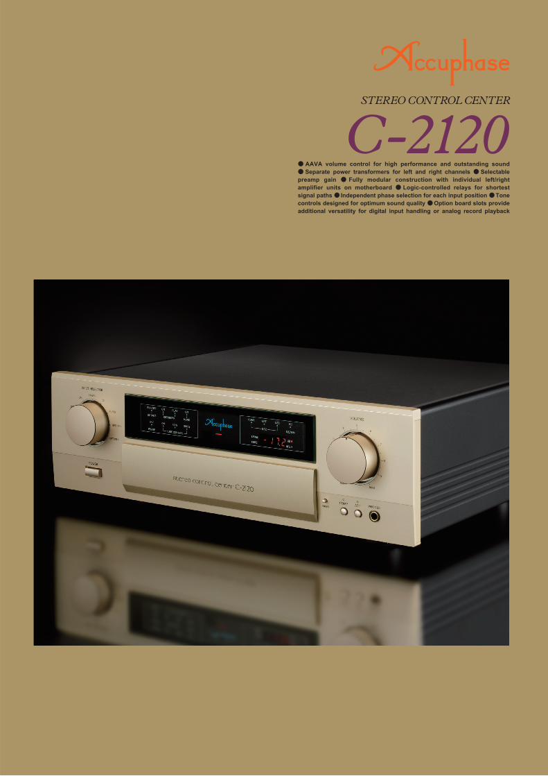
c-2120 brochiure - accuphase · amplifier units on motherboard logic-controlled relays for shortest...
TRANSCRIPT
[Guaranteed specifications are measured according to EIA standard RS-490.]
InputFor rated output
252 mV252 mV
63 mV63 mV
For 0.5 V output40 kilohms (20/20 kilohms)
20 kilohms
Input impedance
BALANCEDLINE
Sensitivity
Input
109 dB109 dB
107 dB107 dB
S/N ratio (EIA)
BALANCEDLINE
Input shorted, A-weightingS/N ratio at rated output
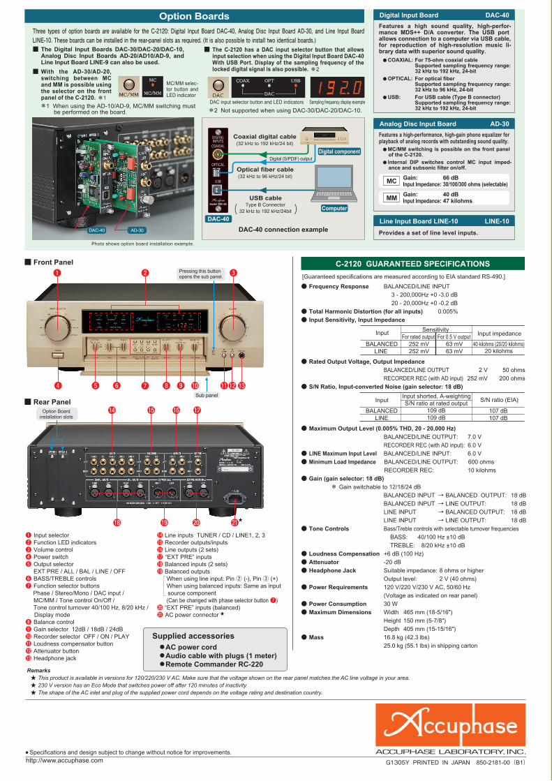
DAC-40 connection example
Computer
DAC-40
Digital componentDigital (S/PDIF) output
Optical fiber cable(32 kHz to 96 kHz/24 bit)
USB cable
Coaxial digital cable(32 kHz to 192 kHz/24 bit)
Type B Connector32 kHz to 192 kHz/24bit
!4 !5 !6
!8 @0!9 @1
!7
r !2u !1
q
y
w
!0oi
e
t !3
DAC-40 AD-30
Sub panel
Pressing this button opens the sub panel.
Option Board installation slots
Photo shows option board installation example.
Sampling frequency display exampleDAC input selector button and LED indicators
MC/MM selec-tor button and LED indicator
q Input selectorw Function LED indicatorse Volume controlr Power switcht Output selector EXT PRE / ALL / BAL / LINE / OFFy BASS/TREBLE controlsu Function selector buttons Phase / Stereo/Mono / DAC input / MC/MM / Tone control On/Off / Tone control turnover 40/100 Hz, 8/20 kHz /
Display modei Balance controlo Gain selector 12dB / 18dB / 24dB!0 Recorder selector OFF / ON / PLAY!1 Loudness compensator button!2 Attenuator button!3 Headphone jack
!4 Line inputs TUNER / CD / LINE1, 2, 3!5 Recorder outputs/inputs!6 Line outputs (2 sets)!7 “EXT PRE” inputs!8 Balanced inputs (2 sets)!9 Balanced outputs When using line input: Pin w (-), Pin e (+) When using balanced inputs: Same as input
source component (Can be changed with phase selector button u)@0 “EXT PRE” inputs (balanced)@1 AC power connector
C-2120 GUARANTEED SPECIFICATIONS
● AAVA volume control for high performance and outstanding sound ● Separate power transformers for left and right channels ● Selectable preamp gain ● Fully modular construction with individual left/right amplifier units on motherboard ● Logic-controlled relays for shortest signal paths ● Independent phase selection for each input position ● Tone controls designed for optimum sound quality ● Option board slots provide additional versatility for digital input handling or analog record playback
■ Rear Panel
■ Front Panel
Digital Input Board DAC-40
Analog Disc Input Board AD-30
Line Input Board LINE-10 LINE-10
Option Boards
Provides a set of line level inputs.
Features a high sound quality, high-perfor-mance MDS++ D/A converter. The USB port allows connection to a computer via USB cable, for reproduction of high-resolution music li-brary data with superior sound quality.
MM
Features a high-performance, high-gain phono equalizer for playback of analog records with outstanding sound quality.
MC
Gain: 40 dBInput Impedance: 47 kilohms
Gain: 66 dBInput Impedance: 30/100/300 ohms (selectable)
● COAXIAL: For 75-ohm coaxial cable Supported sampling frequency range:
32 kHz to 192 kHz, 24-bit
● OPTICAL: For optical fiber Supported sampling frequency range:
32 kHz to 96 kHz, 24-bit
● USB: For USB cable (Type B connector) Supported sampling frequency range:
32 kHz to 192 kHz, 24-bit
● MC/MM switching is possible on the front panel of the C-2120.
● Internal DIP switches control MC input imped-ance and subsonic filter on/off.
● Frequency Response BALANCED/LINE INPUT
3 - 200,000Hz +0 -3.0 dB
20 - 20,000Hz +0 -0.2 dB
● Total Harmonic Distortion (for all inputs) 0.005%
● Input Sensitivity, Input Impedance
● Rated Output Voltage, Output Impedance
BALANCED/LINE OUTPUT 2 V 50 ohms
RECORDER REC (with AD input) 252 mV 200 ohms
● S/N Ratio, Input-converted Noise (gain selector: 18 dB)
● Maximum Output Level (0.005% THD, 20 - 20,000 Hz)
BALANCED/LINE OUTPUT: 7.0 V
RECORDER REC (with AD input): 6.0 V
● LINE Maximum Input Level BALANCED/LINE INPUT: 6.0 V
● Minimum Load Impedance BALANCED/LINE OUTPUT: 600 ohms
RECORDER REC: 10 kilohms
● Gain (gain selector: 18 dB)
* Gain switchable to 12/18/24 dB
BALANCED INPUT → BALANCED OUTPUT: 18 dB
BALANCED INPUT → LINE OUTPUT: 18 dB
LINE INPUT → BALANCED OUTPUT: 18 dB
LINE INPUT → LINE OUTPUT: 18 dB
● Tone Controls Bass/Treble controls with selectable turnover frequencies
BASS: 40/100 Hz ±10 dB
TREBLE: 8/20 kHz ±10 dB
● Loudness Compensation +6 dB (100 Hz)
● Attenuator -20 dB
● Headphone Jack Suitable impedance: 8 ohms or higher
Output level: 2 V (40 ohms)
● Power Requirements 120 V/220 V/230 V AC, 50/60 Hz
(Voltage as indicated on rear panel)
● Power Consumption 30 W
● Maximum Dimensions Width 465 mm (18-5/16")
Height 150 mm (5-7/8")
Depth 405 mm (15-15/16")
● Mass 16.8 kg (42.3 lbs)
25.0 kg (55.1 lbs) in shipping carton
Three types of option boards are available for the C-2120: Digital Input Board DAC-40, Analog Disc Input Board AD-30, and Line Input Board LINE-10. These boards can be installed in the rear-panel slots as required. (It is also possible to install two identical boards.)■ The Digital Input Boards DAC-30/DAC-20/DAC-10,
Analog Disc Input Boards AD-20/AD10/AD-9, and Line Input Board LINE-9 can also be used.
■ With the AD-30/AD-20, switching between MC and MM is possible using the selector on the front panel of the C-2120. *1
*1 When using the AD-10/AD-9, MC/MM switching must be performed on the board. *2 Not supported when using DAC-30/DAC-20/DAC-10.
■ The C-2120 has a DAC input selector button that allows input selection when using the Digital Input Board DAC-40 With USB Port. Display of the sampling frequency of the locked digital signal is also possible. *2
★
★
●AC power cord●Audio cable with plugs (1 meter)●Remote Commander RC-220
Supplied accessories
● Specifications and design subject to change without notice for improvements.
G1305Y PRINTED IN JAPAN 850-2181-00(B1)
Remarks★ This product is available in versions for 120/220/230 V AC. Make sure that the voltage shown on the rear panel matches the AC line voltage in your area.★ 230 V version has an Eco Mode that switches power off after 120 minutes of inactivity.★ The shape of the AC inlet and plug of the supplied power cord depends on the voltage rating and destination country.
http://www.accuphase.com

AAVA configuration in C-2120
-
Res
po
nse
in d
B
10 100 1k 10k 100k
18
16
14
12
10
8
6
4
2
0
-2
-4
-6
Frequency in Hz
LOUDNESS COMPENSATOR: ON
Res
pons
e in
dB
Boo
stC
ut
Frequency in Hz10 100 1k 10k 100k
16
12
8
4
0
-4
-8
-12
-16
100HzBASS
40Hz8kHz
TREBLE
20kHz
Low frequency range
adjustment rangeBASS
adjustment rangeTREBLE
OUTPUT
EXT PRE
EXT PRE
INPUTSELECTOR
INPUTSELECTOR
RECORDER PHASE
BALANCED UNBALANCEDAMPLIFIER
TUNER
CD
OPTION 2
OPTION 1
LINE 1
LINE 2
LINE 3
CD-BAL
LINE-BAL
REC
PLAY
AAVA(Accuphase Analog Vari-gain Amplifier)
I -V Converter
BalancedOutput
Amplifier
HEADPHONEAMPLIFIER
LEVELFREQDISPLAY
BALANCED
LINE
LEFTCHANNELEXT PRE INPUTS
LEFTCHANNELOUTPUTS
BALANCED
LINE 1
LINE 2
HEADPHONEOUTPUT
from RIGHT channel
REMOTESENSOR
FEEDBACK
2161
21
221
231
2151
V- I Converter
RECORDER
RECORDER
RECORDER
MODE PHASE
BUFFER
BUFFER
OUTPUT
OUTPUT
OUTPUT
OUTPUT EXT PRE
21
-
1-
RIGHTCHANNEL
LEFTCHANNEL
INPUTS
Same as LEFT CHANNEL
VolumeBalanceAttenuator
CPU
2161
I - V
BUFFER
+GAIN
21
221
231
2151
BUFFER
Music signal
INPUT
V- I Converter
16 current switches (65,536 possible combinations)
VolumeBalanceAttenuator
CPU
Reconversion of current into voltage
I -V Converter
OUTPUTCurrent values are added
LEVEL DISPLAY
+
-
OUTPUTINPUT-A1 -A2
HIGH-PASSFILTER
LOW-PASSFILTER
TONE CONTROLBASS
TONE CONTROLTREBLE
F1
F2
TONE TONE
LOW-PASSFILTER
HIGH-PASSFILTER
TONE CONTROLTREBLE
BASSTONE CONTROL
COMPENSATOR TONE
ADDER ADDER
COMPENSATOR
High frequency range
CPU detects position of volume knob and operates current on/off switches according to knob position
Volume knob is turned and position is detected
Conversion into current with 16 weighting stages (1/2 - 1/216)
Logic-controlled relays and line input and output connectors
Logic-controlled relays and balanced input and output connectors
Gain selectorOutput selector
Loudness Compensator Characteristics
LED indicator for “EXT PRE”
■ Supplied Remote commander RC-220
■ Unit amplifier assembly
Allows volume adjust-ment, input source switching, and other operations.
AAVA uses a unit amplifier configura-tion comprising the input buffer, 18 V-I
amplifiers and current switches, current summing circuit, I-V
converter amplifier, etc. Left and right channel circuitry
is kept separate on each board.
Tone Control Characteristics Principle of tone control circuitry (summing active filter)
Selectable tone control turnoverBASS: 40 Hz/100 HzTREBLE: 8 kHz/20 kHz
Signal transmission circuitry consists of five unit amplifiers
arranged separately for left and right channels on a
motherboard, togeth-er with a control
board.
Phase selector button and LED indicator
Sound quality and expandability taken to the next level AAVA volume control for impecca-
ble sonic performance. Modular design of AAVA and other amplifier sections realized in a dual
mono construction with separate power supplies. Preamplifier overall gain selection setting and
phase selection settings for each input position stored in memory. Numeric indication of volume
level. Slots for optional digital input boards with input selector and sampling frequency indica-
tion. Phono equalizer board allows playback of analog records with high sound quality.
AAVA (Accuphase Analog Vari-gain Amplifier) Volume Control■ Total of 18 V-I converter amplifiers, paralleled for
upper two units. Input stage ensures powerful drive capability with two buffer amplifiers.
■ No more left/right tracking differences or crosstalk.■ Amplifier display shows accurate gain as numer-
ic indication.
■ High S/N ratio, low distortion, and uniform frequency response and sound quality at any volume.
■ High-resolution volume control.■ Attenuator and left/right balance control
also implemented by AAVA.
■ Long-term reliability for unchanged per-formance and sound quality.
■ AAVA means processing implemented in analog domain.
■ Same operation feel as a conventional high-quality volume control.
■ Short and straight signal paths, along with logic-controlled relays for signal switching assure high sound quality and long-term reliability.
■ Versatile arrangement of line and balanced input and output connectors.
■ EXT PRE function allows use of external preamplifier.
■ Selectable preamplifier gain with three settings (12 dB, 18 dB, 24 dB).
■ Output phase selectable individually for each input. When INV LED is lit, output phase is inverted. When LED is out, phase is normal.
■ Two rear-panel slots for separately available option boards, with support for digital input selection and sampling frequency indication.
■ Dedicated headphone amplifier optimized for sound quality.
■ Numeric indication of volume level.
■ Tone controls using summing active filters for optimum sound quality.
■ More versatile features:● Provisions for recording and playback
with a recorder.● Loudness compensator enhances low
end presence● Attenuator (-20 dB).
The music signal is converted into 16 types of weighted current by V-I (voltage - current) converting amplifiers [1/2, 1/22, ... 1/215, 1/216]. The 16 currents are turned on or off by 16 current switches, and the combination of switch settings determines the overall volume. The switching operation is controlled by a CPU according to the position of the volume control knob. The combined signal current forms a variable gain circuit that adjusts the volume. Finally, the combined current is converted back into a voltage by an I-V (current - voltage) converter.
Since being founded in 1972, Accuphase has never wavered from its philosophy of creating truly high-class audio components. A thorough dedication to quality in the interest of optimal sound reproduction has allowed the company to introduce many legendary models, highly regarded for their innovativeness, sonic excellence, and solid reliability. The Stereo Control Center C-2120, while inheriting the outstanding design approach and technol-ogy of models such as the C-3800, also represents a full model change from its predecessor C-2110, with further enhanced overall circuitry. It provides the flexibility to handle any kind of source while maximizing its inherent sound quality potential.Accuphase’s ground-breaking AAVA (Accuphase Analog Vari-gain Amplifier) volume control, first introduced in the model C-2800, has been continually further refined and improved. AAVA operates fully in the analog domain, but
it eliminates all potentiometers from the signal path. This has a number of advantages, such as (1) outstanding S/N ratio, (2) extremely low distortion, (3) virtually no change in frequency response and sound quality at any listening level, (4) minimal left/right level differences (tracking errors), and (5) minimal left/right crosstalk. The result is a volume control that far surpasses conventional concepts.The C-2120 features separate power supplies for left and right channel, each with a dedicated power transformer, filtering capacitors and peripheral circuitry. The various unit amplifiers are also entirely separate for the two channels, arranged on a motherboard in fully monaural construction. This prevents unwanted crosstalk and interaction both on the electrical and the physical plane.Preamplifier functionality also has been given due attention, with tone controls, a loudness compensator, recorder connection support and other convenient
features. The phase setting can be made for each input position separately, and EXT PRE connectors offer further enhanced flexibility.A range of sophisticated option boards opens up even more possibilities. The newly developed Digital Input Board DAC-40 features a USB port and support for high-bit, high-sampling frequency signals up to 192 kHz/24 bits. This allows reproduction for example of high-quality music library data residing on a computer. The DAC input selector button makes it easy to switch between the optical, coaxial, and USB input. For the first time in a preamplifier, the sampling frequency of a digital signal onto which the amplifier has locked can be shown as a numeric readout. The newly developed Analog Disc Input Board AD-30 is also available, ideal for high-grade reproduction of analog records using either MC or MM phono cartridges.
C-2120 Block Diagram
AAVA operation principleAAVA configuration in C-2120
-
Res
po
nse
in d
B
10 100 1k 10k 100k
18
16
14
12
10
8
6
4
2
0
-2
-4
-6
Frequency in Hz
LOUDNESS COMPENSATOR: ON
Res
pons
e in
dB
Boo
stC
ut
Frequency in Hz10 100 1k 10k 100k
16
12
8
4
0
-4
-8
-12
-16
100HzBASS
40Hz8kHz
TREBLE
20kHz
Low frequency range
adjustment rangeBASS
adjustment rangeTREBLE
OUTPUT
EXT PRE
EXT PRE
INPUTSELECTOR
INPUTSELECTOR
RECORDER PHASE
BALANCED UNBALANCEDAMPLIFIER
TUNER
CD
OPTION 2
OPTION 1
LINE 1
LINE 2
LINE 3
CD-BAL
LINE-BAL
REC
PLAY
AAVA(Accuphase Analog Vari-gain Amplifier)
I -V Converter
BalancedOutput
Amplifier
HEADPHONEAMPLIFIER
LEVELFREQDISPLAY
BALANCED
LINE
LEFTCHANNELEXT PRE INPUTS
LEFTCHANNELOUTPUTS
BALANCED
LINE 1
LINE 2
HEADPHONEOUTPUT
from RIGHT channel
REMOTESENSOR
FEEDBACK
2161
21
221
231
2151
V- I Converter
RECORDER
RECORDER
RECORDER
MODE PHASE
BUFFER
BUFFER
OUTPUT
OUTPUT
OUTPUT
OUTPUT EXT PRE
21
-
1-
RIGHTCHANNEL
LEFTCHANNEL
INPUTS
Same as LEFT CHANNEL
VolumeBalanceAttenuator
CPU
2161
I - V
BUFFER
+GAIN
21
221
231
2151
BUFFER
Music signal
INPUT
V- I Converter
16 current switches (65,536 possible combinations)
VolumeBalanceAttenuator
CPU
Reconversion of current into voltage
I -V Converter
OUTPUTCurrent values are added
LEVEL DISPLAY
+
-
OUTPUTINPUT-A1 -A2
HIGH-PASSFILTER
LOW-PASSFILTER
TONE CONTROLBASS
TONE CONTROLTREBLE
F1
F2
TONE TONE
LOW-PASSFILTER
HIGH-PASSFILTER
TONE CONTROLTREBLE
BASSTONE CONTROL
COMPENSATOR TONE
ADDER ADDER
COMPENSATOR
High frequency range
CPU detects position of volume knob and operates current on/off switches according to knob position
Volume knob is turned and position is detected
Conversion into current with 16 weighting stages (1/2 - 1/216)
Logic-controlled relays and line input and output connectors
Logic-controlled relays and balanced input and output connectors
Gain selectorOutput selector
Loudness Compensator Characteristics
LED indicator for “EXT PRE”
■ Supplied Remote commander RC-220
■ Unit amplifier assembly
Allows volume adjust-ment, input source switching, and other operations.
AAVA uses a unit amplifier configura-tion comprising the input buffer, 18 V-I
amplifiers and current switches, current summing circuit, I-V
converter amplifier, etc. Left and right channel circuitry
is kept separate on each board.
Tone Control Characteristics Principle of tone control circuitry (summing active filter)
Selectable tone control turnoverBASS: 40 Hz/100 HzTREBLE: 8 kHz/20 kHz
Signal transmission circuitry consists of five unit amplifiers
arranged separately for left and right channels on a
motherboard, togeth-er with a control
board.
Phase selector button and LED indicator
Sound quality and expandability taken to the next level AAVA volume control for impecca-
ble sonic performance. Modular design of AAVA and other amplifier sections realized in a dual
mono construction with separate power supplies. Preamplifier overall gain selection setting and
phase selection settings for each input position stored in memory. Numeric indication of volume
level. Slots for optional digital input boards with input selector and sampling frequency indica-
tion. Phono equalizer board allows playback of analog records with high sound quality.
AAVA (Accuphase Analog Vari-gain Amplifier) Volume Control■ Total of 18 V-I converter amplifiers, paralleled for
upper two units. Input stage ensures powerful drive capability with two buffer amplifiers.
■ No more left/right tracking differences or crosstalk.■ Amplifier display shows accurate gain as numer-
ic indication.
■ High S/N ratio, low distortion, and uniform frequency response and sound quality at any volume.
■ High-resolution volume control.■ Attenuator and left/right balance control
also implemented by AAVA.
■ Long-term reliability for unchanged per-formance and sound quality.
■ AAVA means processing implemented in analog domain.
■ Same operation feel as a conventional high-quality volume control.
■ Short and straight signal paths, along with logic-controlled relays for signal switching assure high sound quality and long-term reliability.
■ Versatile arrangement of line and balanced input and output connectors.
■ EXT PRE function allows use of external preamplifier.
■ Selectable preamplifier gain with three settings (12 dB, 18 dB, 24 dB).
■ Output phase selectable individually for each input. When INV LED is lit, output phase is inverted. When LED is out, phase is normal.
■ Two rear-panel slots for separately available option boards, with support for digital input selection and sampling frequency indication.
■ Dedicated headphone amplifier optimized for sound quality.
■ Numeric indication of volume level.
■ Tone controls using summing active filters for optimum sound quality.
■ More versatile features:● Provisions for recording and playback
with a recorder.● Loudness compensator enhances low
end presence● Attenuator (-20 dB).
The music signal is converted into 16 types of weighted current by V-I (voltage - current) converting amplifiers [1/2, 1/22, ... 1/215, 1/216]. The 16 currents are turned on or off by 16 current switches, and the combination of switch settings determines the overall volume. The switching operation is controlled by a CPU according to the position of the volume control knob. The combined signal current forms a variable gain circuit that adjusts the volume. Finally, the combined current is converted back into a voltage by an I-V (current - voltage) converter.
Since being founded in 1972, Accuphase has never wavered from its philosophy of creating truly high-class audio components. A thorough dedication to quality in the interest of optimal sound reproduction has allowed the company to introduce many legendary models, highly regarded for their innovativeness, sonic excellence, and solid reliability. The Stereo Control Center C-2120, while inheriting the outstanding design approach and technol-ogy of models such as the C-3800, also represents a full model change from its predecessor C-2110, with further enhanced overall circuitry. It provides the flexibility to handle any kind of source while maximizing its inherent sound quality potential.Accuphase’s ground-breaking AAVA (Accuphase Analog Vari-gain Amplifier) volume control, first introduced in the model C-2800, has been continually further refined and improved. AAVA operates fully in the analog domain, but
it eliminates all potentiometers from the signal path. This has a number of advantages, such as (1) outstanding S/N ratio, (2) extremely low distortion, (3) virtually no change in frequency response and sound quality at any listening level, (4) minimal left/right level differences (tracking errors), and (5) minimal left/right crosstalk. The result is a volume control that far surpasses conventional concepts.The C-2120 features separate power supplies for left and right channel, each with a dedicated power transformer, filtering capacitors and peripheral circuitry. The various unit amplifiers are also entirely separate for the two channels, arranged on a motherboard in fully monaural construction. This prevents unwanted crosstalk and interaction both on the electrical and the physical plane.Preamplifier functionality also has been given due attention, with tone controls, a loudness compensator, recorder connection support and other convenient
features. The phase setting can be made for each input position separately, and EXT PRE connectors offer further enhanced flexibility.A range of sophisticated option boards opens up even more possibilities. The newly developed Digital Input Board DAC-40 features a USB port and support for high-bit, high-sampling frequency signals up to 192 kHz/24 bits. This allows reproduction for example of high-quality music library data residing on a computer. The DAC input selector button makes it easy to switch between the optical, coaxial, and USB input. For the first time in a preamplifier, the sampling frequency of a digital signal onto which the amplifier has locked can be shown as a numeric readout. The newly developed Analog Disc Input Board AD-30 is also available, ideal for high-grade reproduction of analog records using either MC or MM phono cartridges.
C-2120 Block Diagram
AAVA operation principle

AAVA configuration in C-2120
-
Res
po
nse
in d
B
10 100 1k 10k 100k
18
16
14
12
10
8
6
4
2
0
-2
-4
-6
Frequency in Hz
LOUDNESS COMPENSATOR: ON
Res
pons
e in
dB
Boo
stC
ut
Frequency in Hz10 100 1k 10k 100k
16
12
8
4
0
-4
-8
-12
-16
100HzBASS
40Hz8kHz
TREBLE
20kHz
Low frequency range
adjustment rangeBASS
adjustment rangeTREBLE
OUTPUT
EXT PRE
EXT PRE
INPUTSELECTOR
INPUTSELECTOR
RECORDER PHASE
BALANCED UNBALANCEDAMPLIFIER
TUNER
CD
OPTION 2
OPTION 1
LINE 1
LINE 2
LINE 3
CD-BAL
LINE-BAL
REC
PLAY
AAVA(Accuphase Analog Vari-gain Amplifier)
I -V Converter
BalancedOutput
Amplifier
HEADPHONEAMPLIFIER
LEVELFREQDISPLAY
BALANCED
LINE
LEFTCHANNELEXT PRE INPUTS
LEFTCHANNELOUTPUTS
BALANCED
LINE 1
LINE 2
HEADPHONEOUTPUT
from RIGHT channel
REMOTESENSOR
FEEDBACK
2161
21
221
231
2151
V- I Converter
RECORDER
RECORDER
RECORDER
MODE PHASE
BUFFER
BUFFER
OUTPUT
OUTPUT
OUTPUT
OUTPUT EXT PRE
21
-
1-
RIGHTCHANNEL
LEFTCHANNEL
INPUTS
Same as LEFT CHANNEL
VolumeBalanceAttenuator
CPU
2161
I - V
BUFFER
+GAIN
21
221
231
2151
BUFFER
Music signal
INPUT
V- I Converter
16 current switches (65,536 possible combinations)
VolumeBalanceAttenuator
CPU
Reconversion of current into voltage
I -V Converter
OUTPUTCurrent values are added
LEVEL DISPLAY
+
-
OUTPUTINPUT-A1 -A2
HIGH-PASSFILTER
LOW-PASSFILTER
TONE CONTROLBASS
TONE CONTROLTREBLE
F1
F2
TONE TONE
LOW-PASSFILTER
HIGH-PASSFILTER
TONE CONTROLTREBLE
BASSTONE CONTROL
COMPENSATOR TONE
ADDER ADDER
COMPENSATOR
High frequency range
CPU detects position of volume knob and operates current on/off switches according to knob position
Volume knob is turned and position is detected
Conversion into current with 16 weighting stages (1/2 - 1/216)
Logic-controlled relays and line input and output connectors
Logic-controlled relays and balanced input and output connectors
Gain selectorOutput selector
Loudness Compensator Characteristics
LED indicator for “EXT PRE”
■ Supplied Remote commander RC-220
■ Unit amplifier assembly
Allows volume adjust-ment, input source switching, and other operations.
AAVA uses a unit amplifier configura-tion comprising the input buffer, 18 V-I
amplifiers and current switches, current summing circuit, I-V
converter amplifier, etc. Left and right channel circuitry
is kept separate on each board.
Tone Control Characteristics Principle of tone control circuitry (summing active filter)
Selectable tone control turnoverBASS: 40 Hz/100 HzTREBLE: 8 kHz/20 kHz
Signal transmission circuitry consists of five unit amplifiers
arranged separately for left and right channels on a
motherboard, togeth-er with a control
board.
Phase selector button and LED indicator
Sound quality and expandability taken to the next level AAVA volume control for impecca-
ble sonic performance. Modular design of AAVA and other amplifier sections realized in a dual
mono construction with separate power supplies. Preamplifier overall gain selection setting and
phase selection settings for each input position stored in memory. Numeric indication of volume
level. Slots for optional digital input boards with input selector and sampling frequency indica-
tion. Phono equalizer board allows playback of analog records with high sound quality.
AAVA (Accuphase Analog Vari-gain Amplifier) Volume Control■ Total of 18 V-I converter amplifiers, paralleled for
upper two units. Input stage ensures powerful drive capability with two buffer amplifiers.
■ No more left/right tracking differences or crosstalk.■ Amplifier display shows accurate gain as numer-
ic indication.
■ High S/N ratio, low distortion, and uniform frequency response and sound quality at any volume.
■ High-resolution volume control.■ Attenuator and left/right balance control
also implemented by AAVA.
■ Long-term reliability for unchanged per-formance and sound quality.
■ AAVA means processing implemented in analog domain.
■ Same operation feel as a conventional high-quality volume control.
■ Short and straight signal paths, along with logic-controlled relays for signal switching assure high sound quality and long-term reliability.
■ Versatile arrangement of line and balanced input and output connectors.
■ EXT PRE function allows use of external preamplifier.
■ Selectable preamplifier gain with three settings (12 dB, 18 dB, 24 dB).
■ Output phase selectable individually for each input. When INV LED is lit, output phase is inverted. When LED is out, phase is normal.
■ Two rear-panel slots for separately available option boards, with support for digital input selection and sampling frequency indication.
■ Dedicated headphone amplifier optimized for sound quality.
■ Numeric indication of volume level.
■ Tone controls using summing active filters for optimum sound quality.
■ More versatile features:● Provisions for recording and playback
with a recorder.● Loudness compensator enhances low
end presence● Attenuator (-20 dB).
The music signal is converted into 16 types of weighted current by V-I (voltage - current) converting amplifiers [1/2, 1/22, ... 1/215, 1/216]. The 16 currents are turned on or off by 16 current switches, and the combination of switch settings determines the overall volume. The switching operation is controlled by a CPU according to the position of the volume control knob. The combined signal current forms a variable gain circuit that adjusts the volume. Finally, the combined current is converted back into a voltage by an I-V (current - voltage) converter.
Since being founded in 1972, Accuphase has never wavered from its philosophy of creating truly high-class audio components. A thorough dedication to quality in the interest of optimal sound reproduction has allowed the company to introduce many legendary models, highly regarded for their innovativeness, sonic excellence, and solid reliability. The Stereo Control Center C-2120, while inheriting the outstanding design approach and technol-ogy of models such as the C-3800, also represents a full model change from its predecessor C-2110, with further enhanced overall circuitry. It provides the flexibility to handle any kind of source while maximizing its inherent sound quality potential.Accuphase’s ground-breaking AAVA (Accuphase Analog Vari-gain Amplifier) volume control, first introduced in the model C-2800, has been continually further refined and improved. AAVA operates fully in the analog domain, but
it eliminates all potentiometers from the signal path. This has a number of advantages, such as (1) outstanding S/N ratio, (2) extremely low distortion, (3) virtually no change in frequency response and sound quality at any listening level, (4) minimal left/right level differences (tracking errors), and (5) minimal left/right crosstalk. The result is a volume control that far surpasses conventional concepts.The C-2120 features separate power supplies for left and right channel, each with a dedicated power transformer, filtering capacitors and peripheral circuitry. The various unit amplifiers are also entirely separate for the two channels, arranged on a motherboard in fully monaural construction. This prevents unwanted crosstalk and interaction both on the electrical and the physical plane.Preamplifier functionality also has been given due attention, with tone controls, a loudness compensator, recorder connection support and other convenient
features. The phase setting can be made for each input position separately, and EXT PRE connectors offer further enhanced flexibility.A range of sophisticated option boards opens up even more possibilities. The newly developed Digital Input Board DAC-40 features a USB port and support for high-bit, high-sampling frequency signals up to 192 kHz/24 bits. This allows reproduction for example of high-quality music library data residing on a computer. The DAC input selector button makes it easy to switch between the optical, coaxial, and USB input. For the first time in a preamplifier, the sampling frequency of a digital signal onto which the amplifier has locked can be shown as a numeric readout. The newly developed Analog Disc Input Board AD-30 is also available, ideal for high-grade reproduction of analog records using either MC or MM phono cartridges.
C-2120 Block Diagram
AAVA operation principle
[Guaranteed specifications are measured according to EIA standard RS-490.]
InputFor rated output
252 mV252 mV
63 mV63 mV
For 0.5 V output40 kilohms (20/20 kilohms)
20 kilohms
Input impedance
BALANCEDLINE
Sensitivity
Input
109 dB109 dB
107 dB107 dB
S/N ratio (EIA)
BALANCEDLINE
Input shorted, A-weightingS/N ratio at rated output
DAC-40 connection example
Computer
DAC-40
Digital componentDigital (S/PDIF) output
Optical fiber cable(32 kHz to 96 kHz/24 bit)
USB cable
Coaxial digital cable(32 kHz to 192 kHz/24 bit)
Type B Connector32 kHz to 192 kHz/24bit
!4 !5 !6
!8 @0!9 @1
!7
r !2u !1
q
y
w
!0oi
e
t !3
DAC-40 AD-30
Sub panel
Pressing this button opens the sub panel.
Option Board installation slots
Photo shows option board installation example.
Sampling frequency display exampleDAC input selector button and LED indicators
MC/MM selec-tor button and LED indicator
q Input selectorw Function LED indicatorse Volume controlr Power switcht Output selector EXT PRE / ALL / BAL / LINE / OFFy BASS/TREBLE controlsu Function selector buttons Phase / Stereo/Mono / DAC input / MC/MM / Tone control On/Off / Tone control turnover 40/100 Hz, 8/20 kHz /
Display modei Balance controlo Gain selector 12dB / 18dB / 24dB!0 Recorder selector OFF / ON / PLAY!1 Loudness compensator button!2 Attenuator button!3 Headphone jack
!4 Line inputs TUNER / CD / LINE1, 2, 3!5 Recorder outputs/inputs!6 Line outputs (2 sets)!7 “EXT PRE” inputs!8 Balanced inputs (2 sets)!9 Balanced outputs When using line input: Pin w (-), Pin e (+) When using balanced inputs: Same as input
source component (Can be changed with phase selector button u)@0 “EXT PRE” inputs (balanced)@1 AC power connector
C-2120 GUARANTEED SPECIFICATIONS
● AAVA volume control for high performance and outstanding sound ● Separate power transformers for left and right channels ● Selectable preamp gain ● Fully modular construction with individual left/right amplifier units on motherboard ● Logic-controlled relays for shortest signal paths ● Independent phase selection for each input position ● Tone controls designed for optimum sound quality ● Option board slots provide additional versatility for digital input handling or analog record playback
■ Rear Panel
■ Front Panel
Digital Input Board DAC-40
Analog Disc Input Board AD-30
Line Input Board LINE-10 LINE-10
Option Boards
Provides a set of line level inputs.
Features a high sound quality, high-perfor-mance MDS++ D/A converter. The USB port allows connection to a computer via USB cable, for reproduction of high-resolution music li-brary data with superior sound quality.
MM
Features a high-performance, high-gain phono equalizer for playback of analog records with outstanding sound quality.
MC
Gain: 40 dBInput Impedance: 47 kilohms
Gain: 66 dBInput Impedance: 30/100/300 ohms (selectable)
● COAXIAL: For 75-ohm coaxial cable Supported sampling frequency range:
32 kHz to 192 kHz, 24-bit
● OPTICAL: For optical fiber Supported sampling frequency range:
32 kHz to 96 kHz, 24-bit
● USB: For USB cable (Type B connector) Supported sampling frequency range:
32 kHz to 192 kHz, 24-bit
● MC/MM switching is possible on the front panel of the C-2120.
● Internal DIP switches control MC input imped-ance and subsonic filter on/off.
● Frequency Response BALANCED/LINE INPUT
3 - 200,000Hz +0 -3.0 dB
20 - 20,000Hz +0 -0.2 dB
● Total Harmonic Distortion (for all inputs) 0.005%
● Input Sensitivity, Input Impedance
● Rated Output Voltage, Output Impedance
BALANCED/LINE OUTPUT 2 V 50 ohms
RECORDER REC (with AD input) 252 mV 200 ohms
● S/N Ratio, Input-converted Noise (gain selector: 18 dB)
● Maximum Output Level (0.005% THD, 20 - 20,000 Hz)
BALANCED/LINE OUTPUT: 7.0 V
RECORDER REC (with AD input): 6.0 V
● LINE Maximum Input Level BALANCED/LINE INPUT: 6.0 V
● Minimum Load Impedance BALANCED/LINE OUTPUT: 600 ohms
RECORDER REC: 10 kilohms
● Gain (gain selector: 18 dB)
* Gain switchable to 12/18/24 dB
BALANCED INPUT → BALANCED OUTPUT: 18 dB
BALANCED INPUT → LINE OUTPUT: 18 dB
LINE INPUT → BALANCED OUTPUT: 18 dB
LINE INPUT → LINE OUTPUT: 18 dB
● Tone Controls Bass/Treble controls with selectable turnover frequencies
BASS: 40/100 Hz ±10 dB
TREBLE: 8/20 kHz ±10 dB
● Loudness Compensation +6 dB (100 Hz)
● Attenuator -20 dB
● Headphone Jack Suitable impedance: 8 ohms or higher
Output level: 2 V (40 ohms)
● Power Requirements 120 V/220 V/230 V AC, 50/60 Hz
(Voltage as indicated on rear panel)
● Power Consumption 30 W
● Maximum Dimensions Width 465 mm (18-5/16")
Height 150 mm (5-7/8")
Depth 405 mm (15-15/16")
● Mass 16.8 kg (42.3 lbs)
25.0 kg (55.1 lbs) in shipping carton
Three types of option boards are available for the C-2120: Digital Input Board DAC-40, Analog Disc Input Board AD-30, and Line Input Board LINE-10. These boards can be installed in the rear-panel slots as required. (It is also possible to install two identical boards.)■ The Digital Input Boards DAC-30/DAC-20/DAC-10,
Analog Disc Input Boards AD-20/AD10/AD-9, and Line Input Board LINE-9 can also be used.
■ With the AD-30/AD-20, switching between MC and MM is possible using the selector on the front panel of the C-2120. *1
*1 When using the AD-10/AD-9, MC/MM switching must be performed on the board. *2 Not supported when using DAC-30/DAC-20/DAC-10.
■ The C-2120 has a DAC input selector button that allows input selection when using the Digital Input Board DAC-40 With USB Port. Display of the sampling frequency of the locked digital signal is also possible. *2
★
★
●AC power cord●Audio cable with plugs (1 meter)●Remote Commander RC-220
Supplied accessories
● Specifications and design subject to change without notice for improvements.
G1305Y PRINTED IN JAPAN 850-2181-00(B1)
Remarks★ This product is available in versions for 120/220/230 V AC. Make sure that the voltage shown on the rear panel matches the AC line voltage in your area.★ 230 V version has an Eco Mode that switches power off after 120 minutes of inactivity.★ The shape of the AC inlet and plug of the supplied power cord depends on the voltage rating and destination country.
http://www.accuphase.com