c-3. wet pond - north carolina mineral and land resources... · c-3. wet pond design objective ......
TRANSCRIPT
NCDEQ Stormwater Design Manual
________________________________________________________________________________________________________
C-3. Wet Pond 1 Revised: 4-18-2017
C-3. Wet Pond
Design Objective
A wet pond shall be designed to capture the design storm and release it slowly over a period of two to five days via a properly design outlet structure. Stormwater shall have an adequate flow path to bring about removal of TSS through dilution and settling. The pond shall be designed in a manner that protects the device, the areas around the device and the receiving stream from erosion. The pond also must be maintained properly to prevent the resuspension of captured sediments.
Design Volume
The design volume for a wet pond is equivalent to the volume that is retained for a two to five-day period between the temporary pool elevation and the permanent pool elevation.
Important Links
Rule 15A NCAC 2H .1053. MDC for Wet Ponds
SCM Credit Document, C-3. Credit for Wet Ponds
NCDEQ Stormwater Design Manual
________________________________________________________________________________________________________
C-3. Wet Pond 2 Revised: 4-18-2017
Table of Contents
Guidance on the MDC MDC 1: Main Pool Surface Area and Volume MDC 2: Main Pool Depth MDC 3: Sediment Storage MDC 4: Location of Inlet(s) and Outlet MDC 5: Forebay MDC 6: Vegetated Shelf MDC 7: Drawdown Time MDC 8: Protection of the Receiving Stream MDC 9: Fountains MDC 10: Trash Rack MDC 11: Vegetation Recommendations Recommendation 1: Outlet Structure Recommendation 2: Emergency Spillway Recommendation 3: Irrigation Recommendation 4: Safety
Recommendation 5: Temperature Control Design Variants Maintenance Old Versus New Design Standards
NCDEQ Stormwater Design Manual
________________________________________________________________________________________________________
C-3. Wet Pond 3 Revised: 4-18-2017
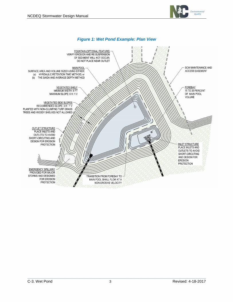
Figure 1: Wet Pond Example: Plan View
NCDEQ Stormwater Design Manual
________________________________________________________________________________________________________
C-3. Wet Pond 4 Revised: 4-18-2017
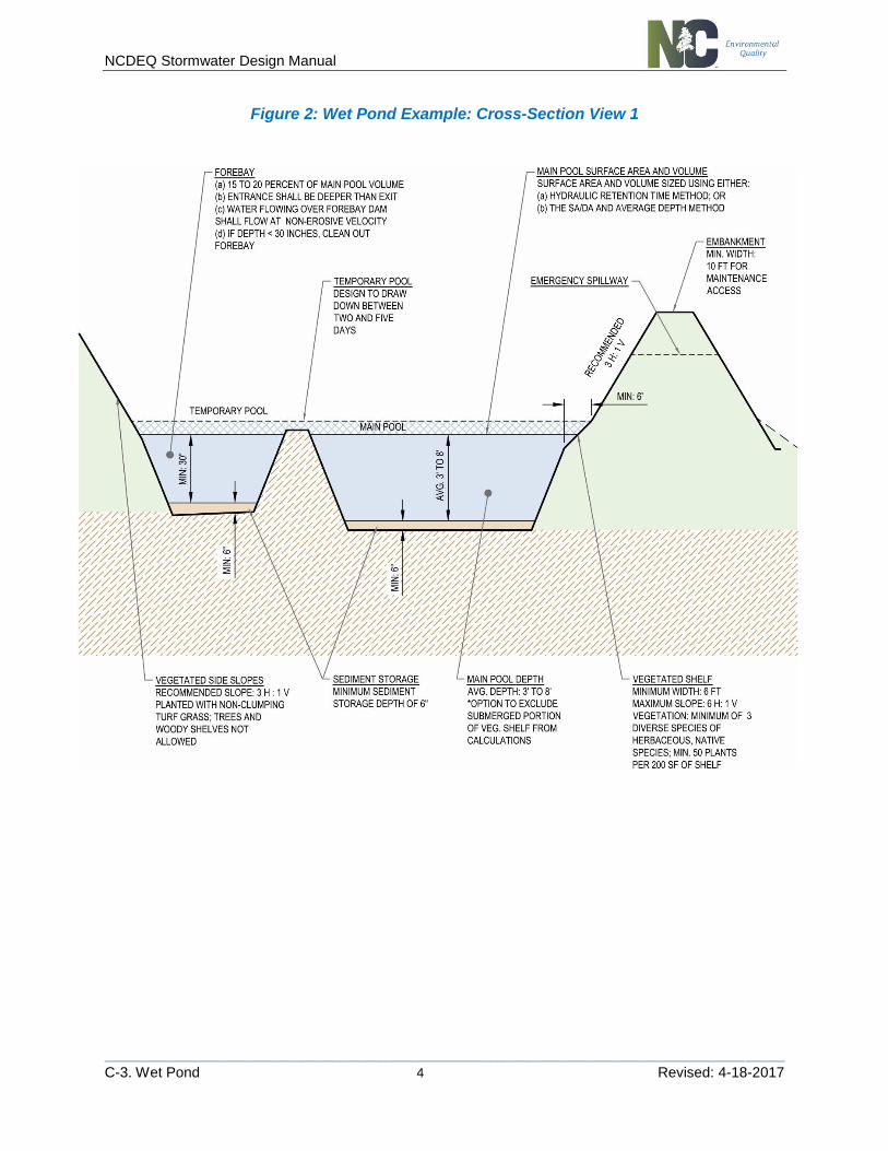
Figure 2: Wet Pond Example: Cross-Section View 1

NCDEQ Stormwater Design Manual
________________________________________________________________________________________________________
C-3. Wet Pond 5 Revised: 4-18-2017
Figure 3: Wet Pond Example: Cross-Section View 2
Figure 4: Wet Pond Example: Outlet Structure
NCDEQ Stormwater Design Manual
________________________________________________________________________________________________________
C-3. Wet Pond 6 Revised: 4-18-2017
Guidance on the MDC MDC 1. MAIN POOL SURFACE AR EA AND VOLUM E
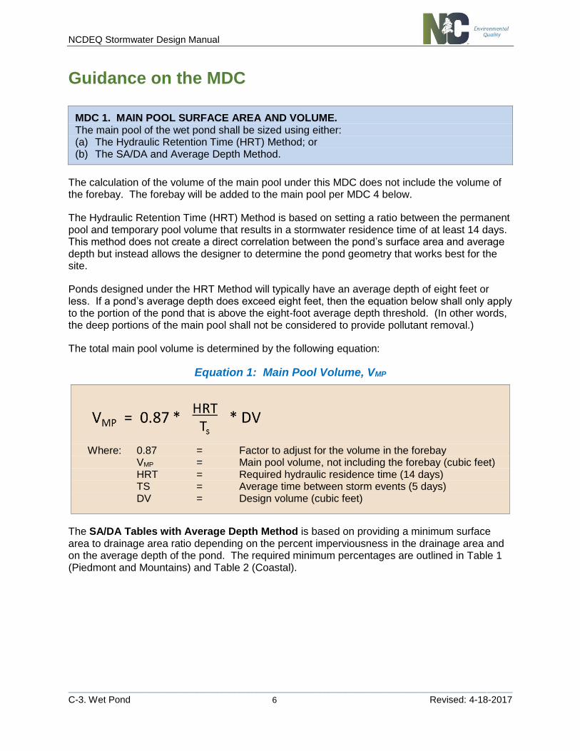
MDC 1. MAIN POOL SURFACE AREA AND VOLUME. The main pool of the wet pond shall be sized using either: (a) The Hydraulic Retention Time (HRT) Method; or (b) The SA/DA and Average Depth Method.
The calculation of the volume of the main pool under this MDC does not include the volume of the forebay. The forebay will be added to the main pool per MDC 4 below.
The Hydraulic Retention Time (HRT) Method is based on setting a ratio between the permanent pool and temporary pool volume that results in a stormwater residence time of at least 14 days. This method does not create a direct correlation between the pond’s surface area and average depth but instead allows the designer to determine the pond geometry that works best for the site.
Ponds designed under the HRT Method will typically have an average depth of eight feet or less. If a pond’s average depth does exceed eight feet, then the equation below shall only apply to the portion of the pond that is above the eight-foot average depth threshold. (In other words, the deep portions of the main pool shall not be considered to provide pollutant removal.)
The total main pool volume is determined by the following equation:
Equation 1: Main Pool Volume, VMP
Where: 0.87 = Factor to adjust for the volume in the forebay VMP = Main pool volume, not including the forebay (cubic feet) HRT = Required hydraulic residence time (14 days) TS = Average time between storm events (5 days) DV = Design volume (cubic feet)
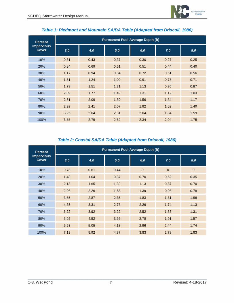
The SA/DA Tables with Average Depth Method is based on providing a minimum surface area to drainage area ratio depending on the percent imperviousness in the drainage area and on the average depth of the pond. The required minimum percentages are outlined in Table 1 (Piedmont and Mountains) and Table 2 (Coastal).
NCDEQ Stormwater Design Manual
________________________________________________________________________________________________________
C-3. Wet Pond 7 Revised: 4-18-2017
Table 1: Piedmont and Mountain SA/DA Table (Adapted from Driscoll, 1986)
Percent Impervious
Cover
Permanent Pool Average Depth (ft)
3.0 4.0 5.0 6.0 7.0 8.0
10% 0.51 0.43 0.37 0.30 0.27 0.25
20% 0.84 0.69 0.61 0.51 0.44 0.40
30% 1.17 0.94 0.84 0.72 0.61 0.56
40% 1.51 1.24 1.09 0.91 0.78 0.71
50% 1.79 1.51 1.31 1.13 0.95 0.87
60% 2.09 1.77 1.49 1.31 1.12 1.03
70% 2.51 2.09 1.80 1.56 1.34 1.17
80% 2.92 2.41 2.07 1.82 1.62 1.40
90% 3.25 2.64 2.31 2.04 1.84 1.59
100% 3.55 2.79 2.52 2.34 2.04 1.75
Table 2: Coastal SA/DA Table (Adapted from Driscoll, 1986)
Percent Impervious
Cover
Permanent Pool Average Depth (ft)
3.0 4.0 5.0 6.0 7.0 8.0
10% 0.78 0.61 0.44 0 0 0
20% 1.48 1.04 0.87 0.70 0.52 0.35
30% 2.18 1.65 1.39 1.13 0.87 0.70
40% 2.96 2.26 1.83 1.39 0.96 0.78
50% 3.65 2.87 2.35 1.83 1.31 1.96
60% 4.35 3.31 2.78 2.26 1.74 1.13
70% 5.22 3.92 3.22 2.52 1.83 1.31
80% 5.92 4.52 3.65 2.78 1.91 1.57
90% 6.53 5.05 4.18 2.96 2.44 1.74
100% 7.13 5.92 4.87 3.83 2.78 1.83
NCDEQ Stormwater Design Manual
________________________________________________________________________________________________________
C-3. Wet Pond 8 Revised: 4-18-2017
MDC 2: MAIN POOL DEPTH
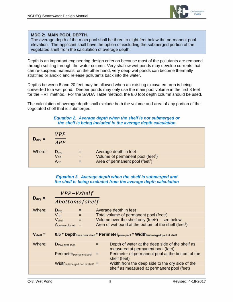
MDC 2: MAIN POOL DEPTH. The average depth of the main pool shall be three to eight feet below the permanent pool elevation. The applicant shall have the option of excluding the submerged portion of the vegetated shelf from the calculation of average depth.
Depth is an important engineering design criterion because most of the pollutants are removed through settling through the water column. Very shallow wet ponds may develop currents that can re-suspend materials; on the other hand, very deep wet ponds can become thermally stratified or anoxic and release pollutants back into the water.
Depths between 8 and 20 feet may be allowed when an existing excavated area is being converted to a wet pond. Deeper ponds may only use the main pool volume in the first 8 feet for the HRT method. For the SA/DA Table method, the 8.0 foot depth column should be used.
The calculation of average depth shall exclude both the volume and area of any portion of the vegetated shelf that is submerged.
Equation 2. Average depth when the shelf is not submerged or the shelf is being included in the average depth calculation
Davg = 𝑉𝑃𝑃
𝐴𝑃𝑃
Where: Davg = Average depth in feet VPP = Volume of permanent pool (feet3) APP = Area of permanent pool (feet2)
Equation 3. Average depth when the shelf is submerged and the shelf is being excluded from the average depth calculation
Davg = 𝑉𝑃𝑃−𝑉𝑠ℎ𝑒𝑙𝑓
𝐴𝑏𝑜𝑡𝑡𝑜𝑚𝑜𝑓𝑠ℎ𝑒𝑙𝑓
Where: Davg = Average depth in feet VPP = Total volume of permanent pool (feet3) Vshelf = Volume over the shelf only (feet3) – see below Abottom of shelf = Area of wet pond at the bottom of the shelf (feet2)
Vshelf = 0.5 * Depthmax over shelf * Perimeterperm pool * Widthsubmerged part of shelf Where: Dmax over shelf = Depth of water at the deep side of the shelf as
measured at permanent pool (feet) Perimeterpermanent pool = Perimeter of permanent pool at the bottom of the shelf (feet) Widthsubmerged part of shelf = Width from the deep side to the dry side of the shelf as measured at permanent pool (feet)
NCDEQ Stormwater Design Manual
________________________________________________________________________________________________________
C-3. Wet Pond 9 Revised: 4-18-2017
MDC 3: SEDIM ENT STOR AGE
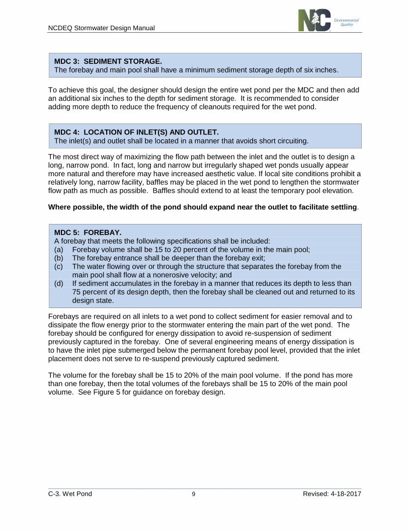
MDC 3: SEDIMENT STORAGE. The forebay and main pool shall have a minimum sediment storage depth of six inches.
To achieve this goal, the designer should design the entire wet pond per the MDC and then add an additional six inches to the depth for sediment storage. It is recommended to consider adding more depth to reduce the frequency of cleanouts required for the wet pond.
MDC 4: LOC ATION OF IN LET( S) AND OUTLET
MDC 4: LOCATION OF INLET(S) AND OUTLET.
The inlet(s) and outlet shall be located in a manner that avoids short circuiting.
The most direct way of maximizing the flow path between the inlet and the outlet is to design a long, narrow pond. In fact, long and narrow but irregularly shaped wet ponds usually appear more natural and therefore may have increased aesthetic value. If local site conditions prohibit a relatively long, narrow facility, baffles may be placed in the wet pond to lengthen the stormwater flow path as much as possible. Baffles should extend to at least the temporary pool elevation.
Where possible, the width of the pond should expand near the outlet to facilitate settling.
MDC 5: FOR EBAY
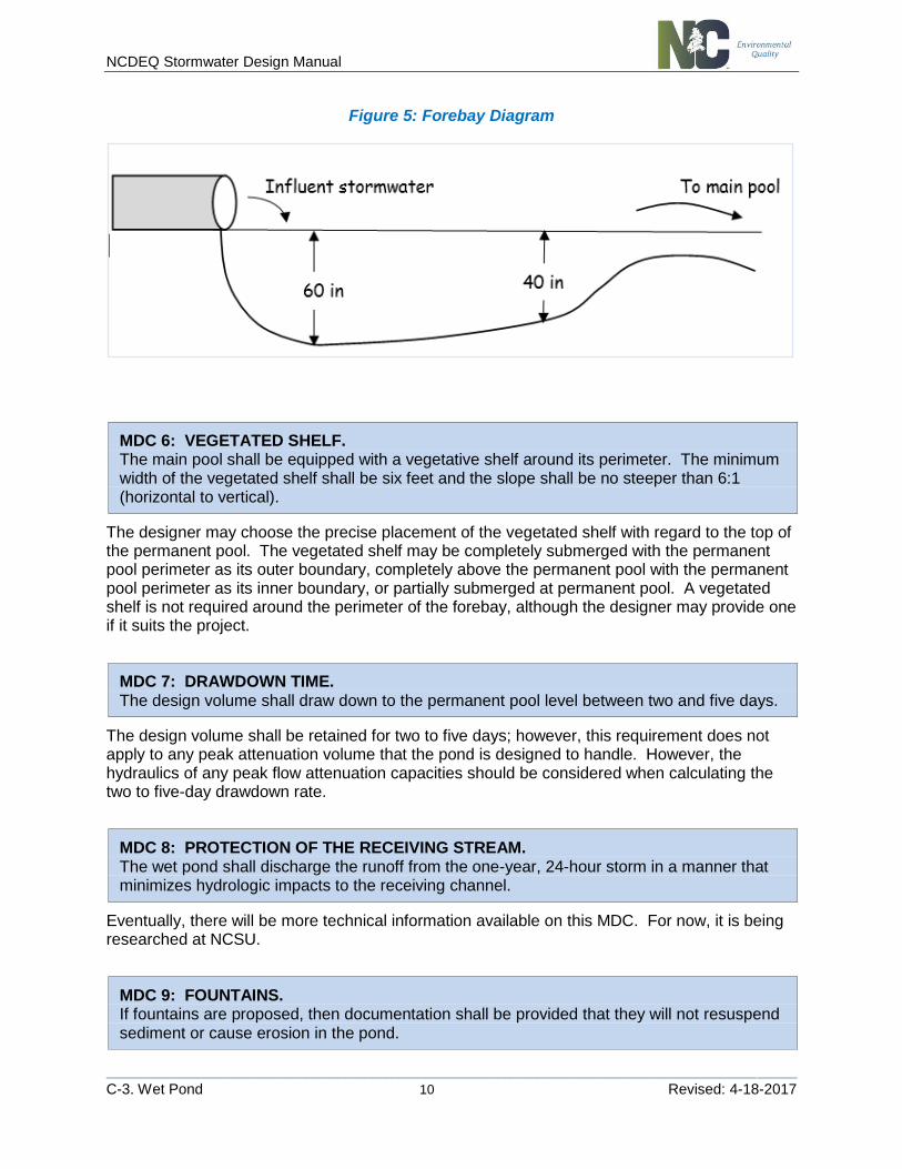
MDC 5: FOREBAY. A forebay that meets the following specifications shall be included: (a) Forebay volume shall be 15 to 20 percent of the volume in the main pool; (b) The forebay entrance shall be deeper than the forebay exit; (c) The water flowing over or through the structure that separates the forebay from the
main pool shall flow at a nonerosive velocity; and (d) If sediment accumulates in the forebay in a manner that reduces its depth to less than
75 percent of its design depth, then the forebay shall be cleaned out and returned to its design state.
Forebays are required on all inlets to a wet pond to collect sediment for easier removal and to dissipate the flow energy prior to the stormwater entering the main part of the wet pond. The forebay should be configured for energy dissipation to avoid re-suspension of sediment previously captured in the forebay. One of several engineering means of energy dissipation is to have the inlet pipe submerged below the permanent forebay pool level, provided that the inlet placement does not serve to re-suspend previously captured sediment.
The volume for the forebay shall be 15 to 20% of the main pool volume. If the pond has more than one forebay, then the total volumes of the forebays shall be 15 to 20% of the main pool volume. See Figure 5 for guidance on forebay design.
NCDEQ Stormwater Design Manual
________________________________________________________________________________________________________
C-3. Wet Pond 10 Revised: 4-18-2017
Figure 5: Forebay Diagram
MDC 6: VEGETATED SH ELF
MDC 6: VEGETATED SHELF. The main pool shall be equipped with a vegetative shelf around its perimeter. The minimum width of the vegetated shelf shall be six feet and the slope shall be no steeper than 6:1 (horizontal to vertical).
The designer may choose the precise placement of the vegetated shelf with regard to the top of the permanent pool. The vegetated shelf may be completely submerged with the permanent pool perimeter as its outer boundary, completely above the permanent pool with the permanent pool perimeter as its inner boundary, or partially submerged at permanent pool. A vegetated shelf is not required around the perimeter of the forebay, although the designer may provide one if it suits the project.
MDC 7: DRAWD OWN TIM E
MDC 7: DRAWDOWN TIME.
The design volume shall draw down to the permanent pool level between two and five days.
The design volume shall be retained for two to five days; however, this requirement does not apply to any peak attenuation volume that the pond is designed to handle. However, the hydraulics of any peak flow attenuation capacities should be considered when calculating the two to five-day drawdown rate.
MDC 8: PR OTECTION OF THE REC EIVIN G STREAM
MDC 8: PROTECTION OF THE RECEIVING STREAM. The wet pond shall discharge the runoff from the one-year, 24-hour storm in a manner that minimizes hydrologic impacts to the receiving channel.
Eventually, there will be more technical information available on this MDC. For now, it is being researched at NCSU.
MDC 9: FOUN TAIN S
MDC 9: FOUNTAINS. If fountains are proposed, then documentation shall be provided that they will not resuspend sediment or cause erosion in the pond.
NCDEQ Stormwater Design Manual
________________________________________________________________________________________________________
C-3. Wet Pond 11 Revised: 4-18-2017
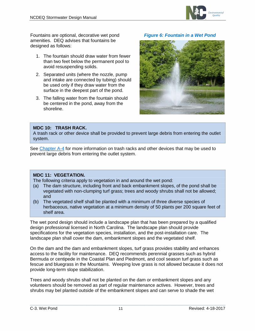
Fountains are optional, decorative wet pond amenities. DEQ advises that fountains be designed as follows:
1. The fountain should draw water from fewer than two feet below the permanent pool to avoid resuspending solids.
2. Separated units (where the nozzle, pump and intake are connected by tubing) should be used only if they draw water from the surface in the deepest part of the pond.
3. The falling water from the fountain should be centered in the pond, away from the shoreline.
Figure 6: Fountain in a Wet Pond
MDC 10: TRASH R AC K
MDC 10: TRASH RACK. A trash rack or other device shall be provided to prevent large debris from entering the outlet system.
See Chapter A-4 for more information on trash racks and other devices that may be used to prevent large debris from entering the outlet system.
MDC 11: VEGETAT ION
MDC 11: VEGETAT ION
MDC 11: VEGETATION. The following criteria apply to vegetation in and around the wet pond: (a) The dam structure, including front and back embankment slopes, of the pond shall be
vegetated with non-clumping turf grass; trees and woody shrubs shall not be allowed; and
(b) The vegetated shelf shall be planted with a minimum of three diverse species of herbaceous, native vegetation at a minimum density of 50 plants per 200 square feet of shelf area.
The wet pond design should include a landscape plan that has been prepared by a qualified design professional licensed in North Carolina. The landscape plan should provide specifications for the vegetation species, installation, and the post-installation care. The landscape plan shall cover the dam, embankment slopes and the vegetated shelf.
On the dam and the dam and embankment slopes, turf grass provides stability and enhances access to the facility for maintenance. DEQ recommends perennial grasses such as hybrid Bermuda or centipede in the Coastal Plan and Piedmont, and cool season turf grass such as fescue and bluegrass in the Mountains. Weeping love grass is not allowed because it does not provide long-term slope stabilization.
Trees and woody shrubs shall not be planted on the dam or embankment slopes and any volunteers should be removed as part of regular maintenance actives. However, trees and shrubs may bel planted outside of the embankment slopes and can serve to shade the wet
NCDEQ Stormwater Design Manual
________________________________________________________________________________________________________
C-3. Wet Pond 12 Revised: 4-18-2017
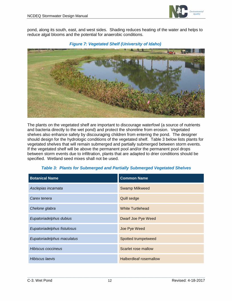
pond, along its south, east, and west sides. Shading reduces heating of the water and helps to reduce algal blooms and the potential for anaerobic conditions.
Figure 7: Vegetated Shelf (University of Idaho)
The plants on the vegetated shelf are important to discourage waterfowl (a source of nutrients and bacteria directly to the wet pond) and protect the shoreline from erosion. Vegetated shelves also enhance safety by discouraging children from entering the pond. The designer should design for the hydrologic conditions of the vegetated shelf. Table 3 below lists plants for vegetated shelves that will remain submerged and partially submerged between storm events. If the vegetated shelf will be above the permanent pool and/or the permanent pool drops between storm events due to infiltration, plants that are adapted to drier conditions should be specified. Wetland seed mixes shall not be used.
Table 3: Plants for Submerged and Partially Submerged Vegetated Shelves
Botanical Name Common Name
Asclepias incarnata Swamp Milkweed
Carex tenera Quill sedge
Chelone glabra White Turtlehead
Eupatoriadelphus dubius Dwarf Joe Pye Weed
Eupatoriadelphus fistulosus Joe Pye Weed
Eupatoriadelphus maculatus Spotted trumpetweed
Hibiscus coccineus Scarlet rose mallow
Hibiscus laevis Halberdleaf rosemallow
NCDEQ Stormwater Design Manual
________________________________________________________________________________________________________
C-3. Wet Pond 13 Revised: 4-18-2017
Kosteletzkya virginica Seashore Mallow
Lobelia cardinalis Cardinal flower
Lobelia elongata Longleaf lobelia
Lobelia siphilitica Great blue Lobelia
Rhynchospora colorata Starrush whitetop
Saccharum baldwinii Narrow plumegrass
Recommendations RECOMM ENDATION 1: OU TLET STRUCTUR E
RECOMMENDATION 1: OUTLET STRUCTURE. The following recommendations apply to the outlet structure:
(a) A drawdown orifice should have a turned-down elbow in order to prevent trash or other material floating on the surface from clogging the pipe.
(b) The riser should be placed close to the embankment to facilitate maintenance and reduce flotation forces.
(c) The design engineer should calculate flotation force for any outlet design subject to flotation forces.
(d) Measures should be provided along the barrel of the principal spillway to prevent piping.
(e) Durable materials, such as reinforced concrete, are preferable to corrugated metal in most instances. The riser should be placed in or at the face of the embankment such that maintenance access is facilitated and flotation forces are reduced.
In addition to achieving the 2 to 5-day drawdown period, outlets should be designed for ease of maintenance. One possible configuration option of the outlet piping that simplifies maintenance and reduces the potential for obstruction is the submerged orifice arrangement shown in Figure 3 at the beginning of this chapter.
Durable materials, such as reinforced concrete, are preferable to corrugated metal in most instances. The riser should be placed in or at the face of the embankment. By placing the riser close to the embankment, maintenance access is facilitated and flotation forces are reduced. The design engineer must present flotation force calculations for any outlet design subject to flotation forces. See Chapter A-4 for more information about designing outlet structures.
RECOMM ENDATION 2: EM ERGENC Y SPILLWAY
RECOMMENDATION 2: EMERGENCY SPILLWAY.
It is strongly recommended to provide an emergency spillway to prevent structure failure of the embankment structure during large storm events.
NCDEQ Stormwater Design Manual
________________________________________________________________________________________________________
C-3. Wet Pond 14 Revised: 4-18-2017
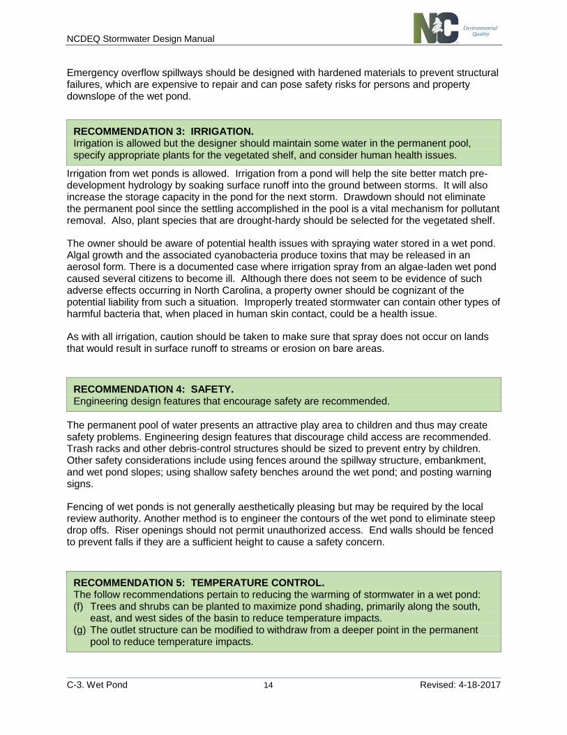
Emergency overflow spillways should be designed with hardened materials to prevent structural failures, which are expensive to repair and can pose safety risks for persons and property downslope of the wet pond.
RECOMM ENDATION 2: IRR IGATION
RECOMMENDATION 3: IRRIGATION. Irrigation is allowed but the designer should maintain some water in the permanent pool, specify appropriate plants for the vegetated shelf, and consider human health issues.
Irrigation from wet ponds is allowed. Irrigation from a pond will help the site better match pre-development hydrology by soaking surface runoff into the ground between storms. It will also increase the storage capacity in the pond for the next storm. Drawdown should not eliminate the permanent pool since the settling accomplished in the pool is a vital mechanism for pollutant removal. Also, plant species that are drought-hardy should be selected for the vegetated shelf.
The owner should be aware of potential health issues with spraying water stored in a wet pond. Algal growth and the associated cyanobacteria produce toxins that may be released in an aerosol form. There is a documented case where irrigation spray from an algae-laden wet pond caused several citizens to become ill. Although there does not seem to be evidence of such adverse effects occurring in North Carolina, a property owner should be cognizant of the potential liability from such a situation. Improperly treated stormwater can contain other types of harmful bacteria that, when placed in human skin contact, could be a health issue.
As with all irrigation, caution should be taken to make sure that spray does not occur on lands that would result in surface runoff to streams or erosion on bare areas.
RECOMM ENDATION 3: SAFETY
RECOMMENDATION 4: SAFETY. Engineering design features that encourage safety are recommended.
The permanent pool of water presents an attractive play area to children and thus may create safety problems. Engineering design features that discourage child access are recommended. Trash racks and other debris-control structures should be sized to prevent entry by children. Other safety considerations include using fences around the spillway structure, embankment, and wet pond slopes; using shallow safety benches around the wet pond; and posting warning signs.
Fencing of wet ponds is not generally aesthetically pleasing but may be required by the local review authority. Another method is to engineer the contours of the wet pond to eliminate steep drop offs. Riser openings should not permit unauthorized access. End walls should be fenced to prevent falls if they are a sufficient height to cause a safety concern.
RECOMM ENDATION 4: TEMPERATUR E C ONTROL
RECOMMENDATION 5: TEMPERATURE CONTROL. The follow recommendations pertain to reducing the warming of stormwater in a wet pond: (f) Trees and shrubs can be planted to maximize pond shading, primarily along the south,
east, and west sides of the basin to reduce temperature impacts. (g) The outlet structure can be modified to withdraw from a deeper point in the permanent
pool to reduce temperature impacts.

NCDEQ Stormwater Design Manual
________________________________________________________________________________________________________
C-3. Wet Pond 15 Revised: 4-18-2017
These recommendations should be considered in trout waters; however, they are helpful to protecting all streams throughout North Carolina.
Design Variants DESIGN VAR IANT 1: FLOATIN G WETLAND ISLAND (FWI)
DESIGN VARIANT 1: FLOATING WETLAND ISLAND (FWI). FWIs may be added as an optional enhancement to wet ponds to increase their effectiveness at removing nutrients. The additional nutrient credits are described in the SCM Credit Document.
FWIs should adhere to the following MDC or an alternative design with equal or greater effectiveness:
(a) The maximum depth for the wet pond shall be 6 feet to ensure that the stormwater is in contact with the roots of the wetland plants.
(b) Wetland mat material shall float, be durable, non-toxic, and capable of supporting plant life, allowing root growth freely through the bottom into the water column.
(c) Floating mats shall be spaced evenly from bank to bank perpendicular to the flow. Floating mats shall be at least 10 feet away from the outlet structure to prevent clogging.
(d) Vegetation shall be obligate wetland plants that are capable of developing thick root masses that hang two to three feet in the water column for optimal water interception.
(e) Plants shall be installed at a density of one plant per 2 square feet. There shall be a minimum of 85% aerial coverage of plants on the mats.
(f) Anchor cable shall be as long as the maximum depth of the pond. Stainless steel or durable plastic cables are recommended for connecting the FTW to a weighted anchor such as cinderblocks at the bottom of the pond). The anchor cable should be inspected annually.
(g) Prior to installing FWIs, the wet pond should be inspected for invasive aquatic weeds so they can be removed. Planting material should be peat moss or potting soil (per manufacturer’s recommendations) installed in pre-drilled holes in the floating mat material.
(h) Fencing should be should be initially be installed over the island to prevent geese & wildlife intrusion while plants are being established. Twine or deer fencing is recommended.
NCDEQ Stormwater Design Manual
________________________________________________________________________________________________________
C-3. Wet Pond 16 Revised: 4-18-2017
Maintenance
Important maintenance procedures for wet ponds include:
1. Immediately after the wet pond is established, the plants on the vegetated shelf and perimeter of the basin should be watered twice weekly if needed, until the plants become established (commonly six weeks).
2. No portion of the wet pond should be fertilized after the first initial fertilization that is required to establish the plants on the vegetated shelf.
3. Stable groundcover should be maintained in the drainage area to reduce the sediment load to the wet pond.
4. If the pond must be drained for an emergency or to perform maintenance, the flushing of sediment through the emergency drain should be minimized as much as possible.
5. Once a year, a dam safety expert should inspect the embankment.
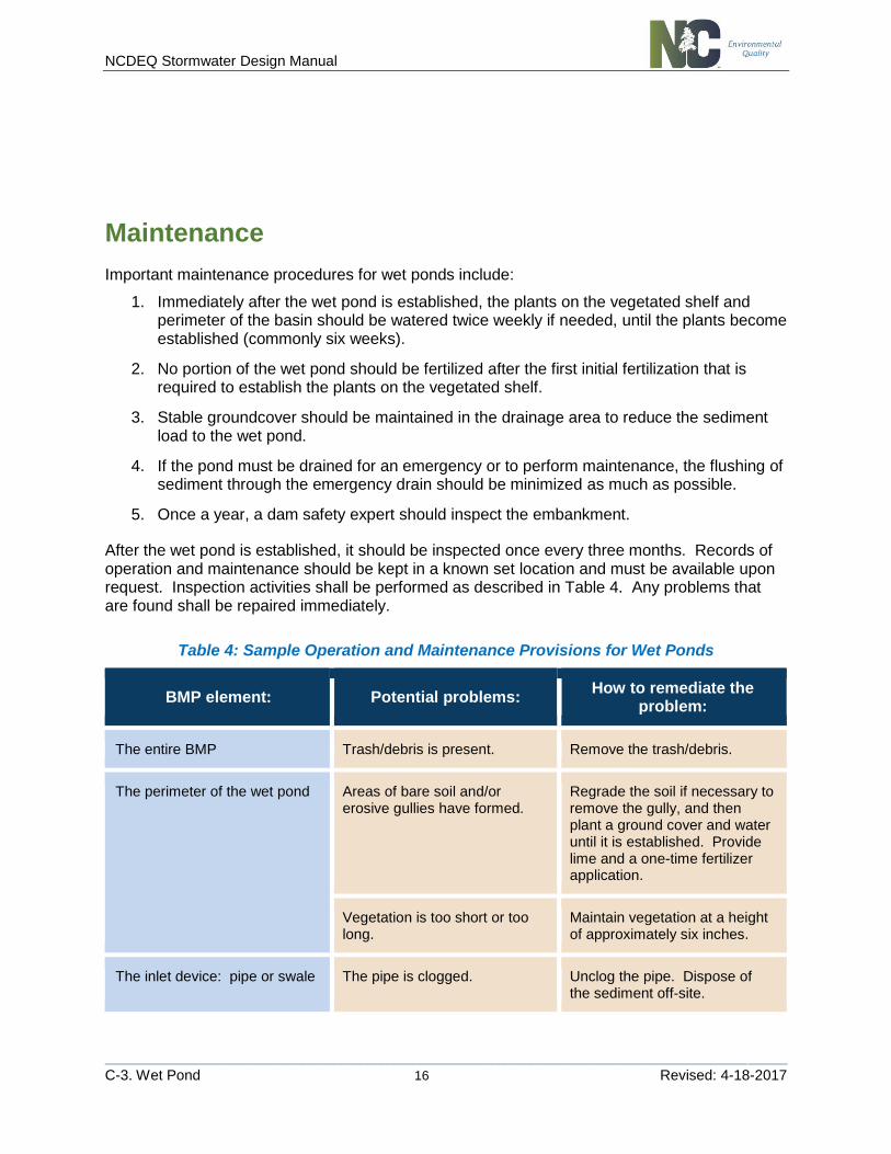
After the wet pond is established, it should be inspected once every three months. Records of operation and maintenance should be kept in a known set location and must be available upon request. Inspection activities shall be performed as described in Table 4. Any problems that are found shall be repaired immediately.
Table 4: Sample Operation and Maintenance Provisions for Wet Ponds
BMP element: Potential problems: How to remediate the
problem:
The entire BMP Trash/debris is present. Remove the trash/debris.
The perimeter of the wet pond Areas of bare soil and/or erosive gullies have formed.
Regrade the soil if necessary to remove the gully, and then plant a ground cover and water until it is established. Provide lime and a one-time fertilizer application.
Vegetation is too short or too long.
Maintain vegetation at a height of approximately six inches.
The inlet device: pipe or swale The pipe is clogged. Unclog the pipe. Dispose of the sediment off-site.
NCDEQ Stormwater Design Manual
________________________________________________________________________________________________________
C-3. Wet Pond 17 Revised: 4-18-2017
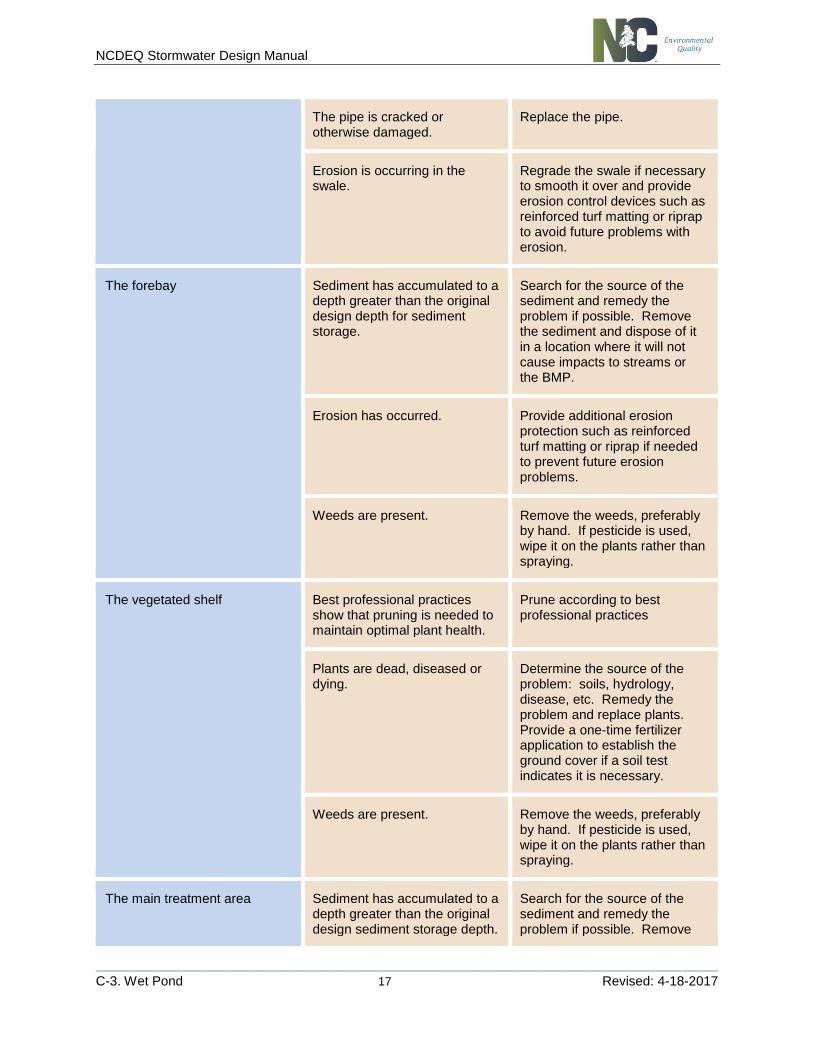
The pipe is cracked or otherwise damaged.
Replace the pipe.
Erosion is occurring in the swale.
Regrade the swale if necessary to smooth it over and provide erosion control devices such as reinforced turf matting or riprap to avoid future problems with erosion.
The forebay Sediment has accumulated to a depth greater than the original design depth for sediment storage.
Search for the source of the sediment and remedy the problem if possible. Remove the sediment and dispose of it in a location where it will not cause impacts to streams or the BMP.
Erosion has occurred. Provide additional erosion protection such as reinforced turf matting or riprap if needed to prevent future erosion problems.
Weeds are present. Remove the weeds, preferably by hand. If pesticide is used, wipe it on the plants rather than spraying.
The vegetated shelf Best professional practices show that pruning is needed to maintain optimal plant health.
Prune according to best professional practices
Plants are dead, diseased or dying.
Determine the source of the problem: soils, hydrology, disease, etc. Remedy the problem and replace plants. Provide a one-time fertilizer application to establish the ground cover if a soil test indicates it is necessary.
Weeds are present. Remove the weeds, preferably by hand. If pesticide is used, wipe it on the plants rather than spraying.
The main treatment area Sediment has accumulated to a depth greater than the original design sediment storage depth.
Search for the source of the sediment and remedy the problem if possible. Remove
NCDEQ Stormwater Design Manual
________________________________________________________________________________________________________
C-3. Wet Pond 18 Revised: 4-18-2017
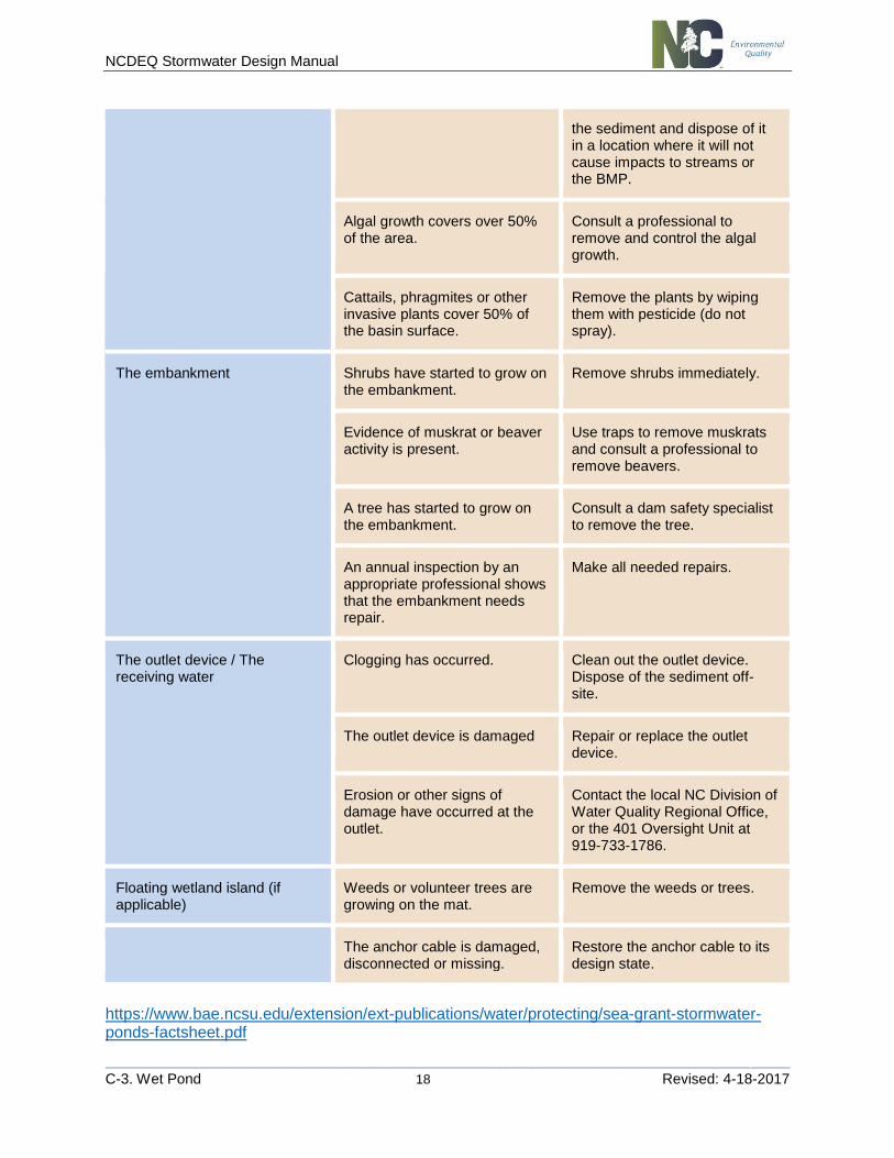
the sediment and dispose of it in a location where it will not cause impacts to streams or the BMP.
Algal growth covers over 50% of the area.
Consult a professional to remove and control the algal growth.
Cattails, phragmites or other invasive plants cover 50% of the basin surface.
Remove the plants by wiping them with pesticide (do not spray).
The embankment Shrubs have started to grow on the embankment.
Remove shrubs immediately.
Evidence of muskrat or beaver activity is present.
Use traps to remove muskrats and consult a professional to remove beavers.
A tree has started to grow on the embankment.
Consult a dam safety specialist to remove the tree.
An annual inspection by an appropriate professional shows that the embankment needs repair.
Make all needed repairs.
The outlet device / The receiving water
Clogging has occurred. Clean out the outlet device. Dispose of the sediment off-site.
The outlet device is damaged Repair or replace the outlet device.
Erosion or other signs of damage have occurred at the outlet.
Contact the local NC Division of Water Quality Regional Office, or the 401 Oversight Unit at 919-733-1786.
Floating wetland island (if applicable)
Weeds or volunteer trees are growing on the mat.
Remove the weeds or trees.
The anchor cable is damaged, disconnected or missing.
Restore the anchor cable to its design state.
https://www.bae.ncsu.edu/extension/ext-publications/water/protecting/sea-grant-stormwater-ponds-factsheet.pdf
NCDEQ Stormwater Design Manual
________________________________________________________________________________________________________
C-3. Wet Pond 19 Revised: 4-18-2017
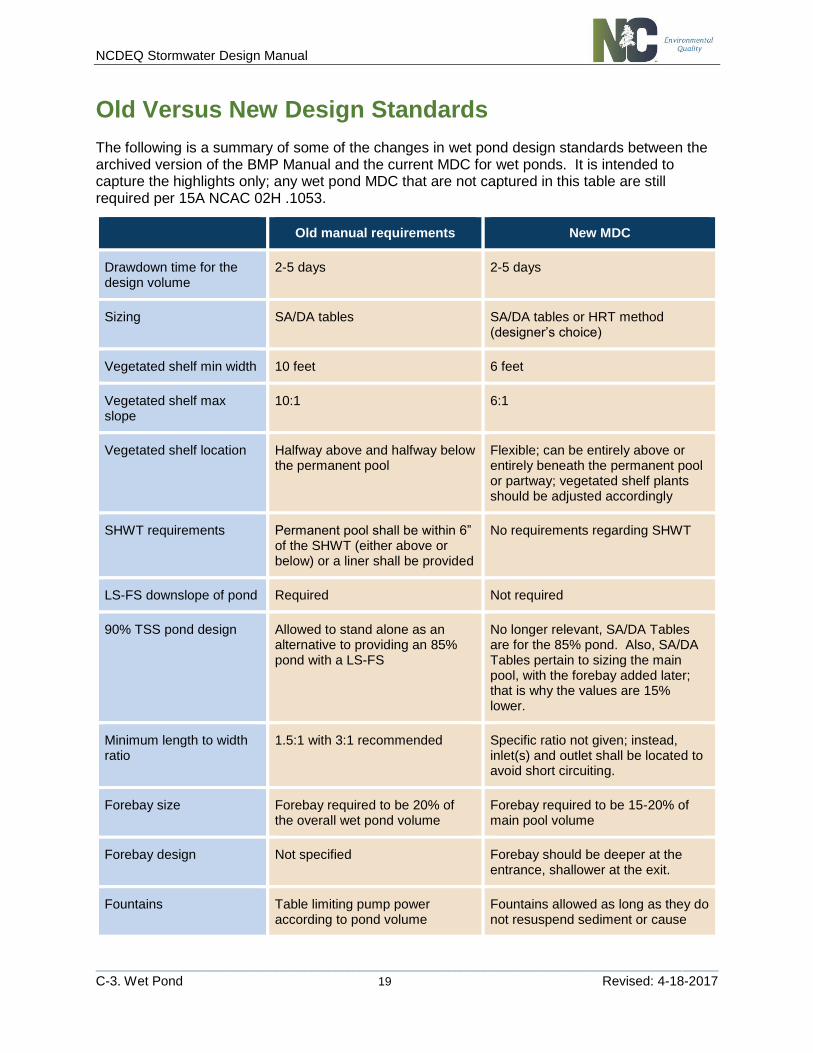
Old Versus New Design Standards
The following is a summary of some of the changes in wet pond design standards between the archived version of the BMP Manual and the current MDC for wet ponds. It is intended to capture the highlights only; any wet pond MDC that are not captured in this table are still required per 15A NCAC 02H .1053.
Old manual requirements New MDC
Drawdown time for the design volume
2-5 days 2-5 days
Sizing SA/DA tables SA/DA tables or HRT method (designer’s choice)
Vegetated shelf min width 10 feet 6 feet
Vegetated shelf max slope
10:1 6:1
Vegetated shelf location Halfway above and halfway below the permanent pool
Flexible; can be entirely above or entirely beneath the permanent pool or partway; vegetated shelf plants should be adjusted accordingly
SHWT requirements Permanent pool shall be within 6” of the SHWT (either above or below) or a liner shall be provided
No requirements regarding SHWT
LS-FS downslope of pond Required Not required
90% TSS pond design Allowed to stand alone as an alternative to providing an 85% pond with a LS-FS
No longer relevant, SA/DA Tables are for the 85% pond. Also, SA/DA Tables pertain to sizing the main pool, with the forebay added later; that is why the values are 15% lower.
Minimum length to width ratio
1.5:1 with 3:1 recommended Specific ratio not given; instead, inlet(s) and outlet shall be located to avoid short circuiting.
Forebay size Forebay required to be 20% of the overall wet pond volume
Forebay required to be 15-20% of main pool volume
Forebay design Not specified Forebay should be deeper at the entrance, shallower at the exit.
Fountains Table limiting pump power according to pond volume
Fountains allowed as long as they do not resuspend sediment or cause

NCDEQ Stormwater Design Manual
________________________________________________________________________________________________________
C-3. Wet Pond 20 Revised: 4-18-2017
erosion around the perimeter of the pond.
Trash rack Not required Trash rack or other device to exclude trash from the outlet structure required.