c a power r workholding l a n e precision vises zero … in international power workholding combined...
TRANSCRIPT

927 Horan Drive n Fenton, MO 63026Phone (636) 386-8022 n Fax (636) 386-8034
Free Engineering Support 1-800-827-2526www.carrlaneroemheld.com
Connect with us: n n n
PW-0816
CARR
LANE
ROEMHELD
MFG
CO
PW
8n
2016
COPYRIGHT © 2016 CARR LANE ROEMHELD MANUFACTURING CO. 16092-0816 PRINTED IN U.S.A.
Authorized Distributor:
Power Workholding n Precision Vises n Zero Point Mounting n Assembly and Handling
PowerWorkholding
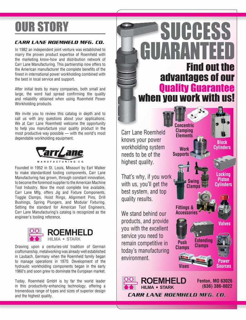
OUR STORYIn 1982 an independent joint venture was established to marry the proven product expertise of Roemheld with the marketing know-how and distribution network of Carr Lane Manufacturing. This partnership now offers to the American manufacturer the complete benefits of the finest in international power workholding combined with the best in local service and support.
After initial tests by many companies, both small and large, the word had spread confirming the quality and reliability obtained when using Roemheld Power Workholding products.
We invite you to review this catalog in depth and to call us with any questions about your applications. We at Carr Lane Roemheld welcome the opportunity to help you manufacture your quality product in the most productive way possible — with the world’s most dependable workholding equipment.
Founded in 1952 in St. Louis, Missouri by Earl Walker to make standardized tooling components, Carr Lane Manufacturing has grown, through constant innovation, to become the foremost supplier to the American Machine Tool Industry. Now the most complete line available, Carr Lane Mfg. offers Jig and Fixture Components, Toggle Clamps, Hoist Rings, Alignment Pins, Drill Bushings, Spring Plungers, and Modular Fixturing. Setting the standard for American Tool Engineers, Carr Lane Manufacturing’s catalog is recognized as the engineer’s tooling reference.
Drawing upon a centuries-old tradition of German craftsmanship, metalworking was already well established in Laubach, Germany when the Roemheld family began to manage operations in 1870. Development of the hydraulic workholding components began in the early 1960’s and soon grew to dominate the European market.
Today, Roemheld GmbH is by far the world leader in this productivity-enhancing technology, offering a tremendous range of types and sizes of superior design and the highest quality.
SUCCESSGUARANTEED
Carr Lane Roemheld knows your power workholding system needs to be of the highest quality.
That’s why, if you work with us, you’ll get the best system, and top quality results.
We stand behind our products, and provide you with the excellent service you need to remain competitive in today’s manufacturing environment.
Work Supports
VisesPower
Sources
Fittings &Accessories
BlockCylinders
Swing Clamps
Concentric Clamping Elements
Extending ClampsPush
Clamps
Fenton, MO 63026(636) 386-8022
Find out theadvantages of ourQuality Guarantee
when you work with us!
Locking Piston
Cylinders
Valves
Fenton, MO 63026(636) 386-8022
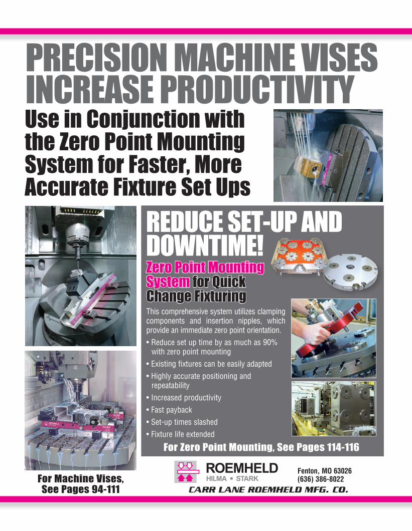
REDUCE SET-UP AND DOWNTIME!
For Zero Point Mounting, See Pages 114-116
Zero Point Mounting System for Quick Change FixturingThis comprehensive system utilizes clamping components and insertion nipples, which provide an immediate zero point orientation.• Reduce set up time by as much as 90%
with zero point mounting• Existing fixtures can be easily adapted• Highly accurate positioning and
repeatability• Increased productivity• Fast payback• Set-up times slashed• Fixture life extended
Use in Conjunction with the Zero Point Mounting System for Faster, More Accurate Fixture Set Ups
PRECISION MACHINE VISES INCREASE PRODUCTIVITY
For Machine Vises,See Pages 94-111

120 8/16
CARR LANE ROEMHELD MFG. CO.Sales — Phone (636) 386-8022 Fax (636) 386-8034
Engineering — Phone 1-800-827-2526 Web www.clrh.com
Power Sources
Standard Electric Power Units are the best power source for most uses. Complete, compact, quiet, and fully automatic. Include pump, reservoir, switches, valves, gauge, and numerous safety devices. Extremely long life. Enough fluid capacity for virtually any fixture. Up to 7500 psi output pressures. 120, 220, or 440 volt.
Economical power source, driven by shop air pressure, includes pump, reservoir, valves, gauges, air filter, muffler, and air extractor/dryer. Very quiet. Ideal for hazardous locations. Enough fluid capacity for virtually any fixture. Up to 7500 psi output pressure.
Air Power Units
Compact Air Power Units are ideal for smaller hydraulic clamping and assembly fixtures with single or double-acting hydraulic elements. Ordinary shop air is all that is required to drive these units.
Air Power Unitspages 128-129
Compact Air Power Unitspage 130
Electric Power Unitspages 124-127
Compact Electric Power Unitspages 122-123
Compact Electric Power Units are compact, light weight, modular units ready for installation. Ideal for operating small and midsize clamping systems, and suitable for both single-acting and double-acting cylinders. These zero leakage systems come complete with motor, pump, oil tank, manifold block, pressure gauge, pressure switch, valves and electrical system.
Electric Power Units
8/16 121
CARR LANE ROEMHELD MFG. CO.Sales — Phone (636) 386-8022 Fax (636) 386-8034
Engineering — Phone 1-800-827-2526 Web www.clrh.com
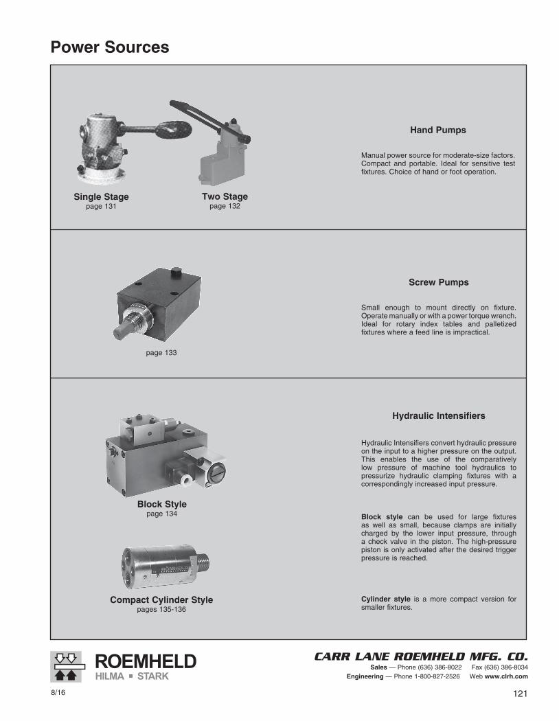
Hand Pumps
Manual power source for moderate-size factors. Compact and portable. Ideal for sensitive test fixtures. Choice of hand or foot operation.
Screw Pumps
Small enough to mount directly on fixture. Operate manually or with a power torque wrench. Ideal for rotary index tables and palletized fixtures where a feed line is impractical.
Hydraulic Intensifiers
Hydraulic Intensifiers convert hydraulic pressure on the input to a higher pressure on the output. This enables the use of the comparatively low pressure of machine tool hydraulics to pressurize hydraulic clamping fixtures with a correspondingly increased input pressure.
Block style can be used for large fixtures as well as small, because clamps are initially charged by the lower input pressure, through a check valve in the piston. The high-pressure piston is only activated after the desired trigger pressure is reached.
Cylinder style is a more compact version for smaller fixtures.
Power Sources
page 133
Single Stagepage 131
Two Stagepage 132
Block Stylepage 134
Compact Cylinder Stylepages 135-136
122 8/16
CARR LANE ROEMHELD MFG. CO.Sales — Phone (636) 386-8022 Fax (636) 386-8034
Engineering — Phone 1-800-827-2526 Web www.clrh.com
Subject to change. For further details, including detailed dimensions and mounting instructions, visit www.clrh.com.
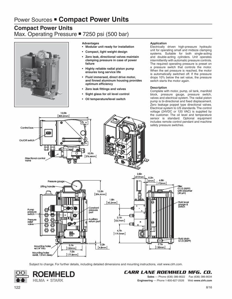
Power Sources n Compact Power UnitsCompact Power UnitsMax. Operating Pressure n 7250 psi (500 bar)
Advantages• Modularunitreadyforinstallation
• Compact,lightweightdesign
• Zeroleak,directionalvalvesmaintainclampingpressureincaseofpowerfailure
• Highlyreliableradialpistonpumpensureslongservicelife
• Fluidimmersed,directdrivemotor,andfinnedaluminumhousingprovidesoptimumefficiency
• Zeroleakfittingsandvalves
• Sightglassforoillevelcontrol
• Oiltemperature/levelswitch
ApplicationElectrically driven high-pressure hydraulic unit for operating small and midsize clamping systems. Suitable for both single-acting and double-acting cylinders. Unit operates intermittently with automatic pressure controls. The required operating pressure is preset on a pressure switch that controls the motor. When the set pressure is reached, the motor is automatically switched off. If the pressure drops 10% below the set value, the pressure switch starts the motor again.
DescriptionComplete with motor, pump, oil tank, manifold block, pressure gauge, pressure switch, valves and electrical system. The radial piston pump is bi-directional and fixed displacement. Zero leakage poppet type directional valves. Electrical system to US standards. The control voltage (24VDC or 120 VAC) is supplied by the customer. The oil level and temperature sensor is standard. Optional equipment includes remote control pendant and machine safety pressure switches.
8/16 123
CARR LANE ROEMHELD MFG. CO.Sales — Phone (636) 386-8022 Fax (636) 386-8034
Engineering — Phone 1-800-827-2526 Web www.clrh.com
Subject to change. For further details, including detailed dimensions and mounting instructions, visit www.clrh.com.
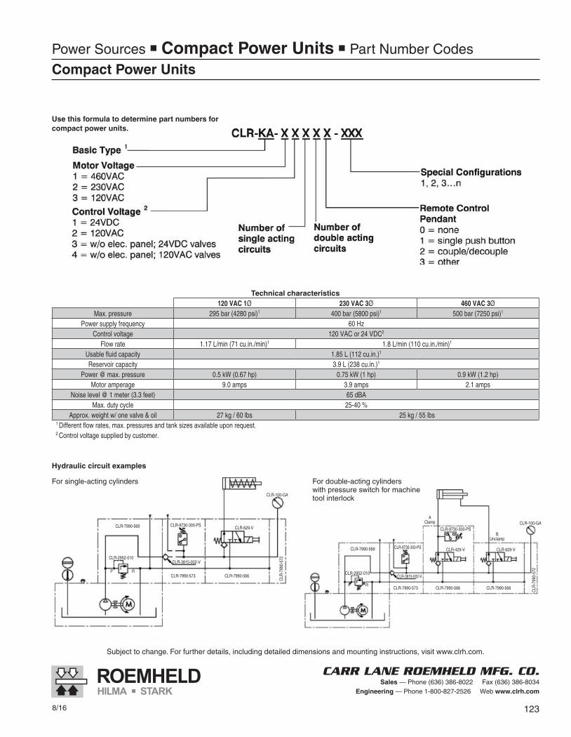
Technical characteristics120 VAC 1Ø 230 VAC 3Ø 460 VAC 3Ø
Max. pressure 295 bar (4280 psi)1 400 bar (5800 psi)1 500 bar (7250 psi)1
Power supply frequency 60 HzControl voltage 120 VAC or 24 VDC2
Flow rate 1.17 L/min (71 cu.in./min)1 1.8 L/min (110 cu.in./min)1
Usable fluid capacity 1.85 L (112 cu.in.)1
Reservoir capacity 3.9 L (238 cu.in.)1
Power @ max. pressure 0.5 kW (0.67 hp) 0.75 kW (1 hp) 0.9 kW (1.2 hp)Motor amperage 9.0 amps 3.9 amps 2.1 amps
Noise level @ 1 meter (3.3 feet) 65 dBAMax. duty cycle 25-40 %
Approx. weight w/ one valve & oil 27 kg / 60 lbs 25 kg / 55 lbs1 Different flow rates, max. pressures and tank sizes available upon request.2 Control voltage supplied by customer.
Use this formula to determine part numbers for compact power units.
Hydraulic circuit examples
For single-acting cylinders For double-acting cylinderswith pressure switch for machine tool interlock
Power Sources n Compact Power Units n Part Number Codes
Compact Power Units
CLR-7990-569 CLR-9730-300-PS CLR-629-V
CLR-2952-010
CLR-2952-010P
P
R
R
CLR-3815-002-V
CLR-7990-573 CLR-7990-566
CLR-
7990
-572
CLR-100-GA
CLR-7990-569 CLR-9730-300-PS
CLR-7990-573 CLR-7990-566 CLR-7990-566
AClamp
BUnclamp
CLR-9730-300-PS
CLR-429-V CLR-629-V
CLR-100-GA
CLR-
7990
-572
CLR-3815-002-V
124 8/16
CARR LANE ROEMHELD MFG. CO.Sales — Phone (636) 386-8022 Fax (636) 386-8034
Engineering — Phone 1-800-827-2526 Web www.clrh.com
All Pump Systems contain Controls and Valve packages ready to go. No add on packages required. Fluid Recommendations are in F&A section.SPECIALS AVAILABLE, CONSULT ENGINEERING 1-800-827-2526
Adjustable Operating Pressure 1160-7250 725-5075 725-5075
460 volts 230 volts 230 volts 115 volts 460 volts 230 volts
Power supply 3 Phase 3 Phase 1 Phase 1 Phase 3 Phase 3 Phase
60Hz 60Hz 60Hz 60Hz 60Hz 60Hz
Flow rate (cu.in/min ) 66 66 66 66 106 106
Usable fluid capacity (cu.in) 400 400 400 400 400 400
Reservoir capacity (cu.in.) 690 690 690 690 690 690
Motor horsepower 1.5 1.5 1.0 1.0 1.5 1.5
Motor amperage 2.1 4.2 6.4 12.8 2.1 4.2
Noise level @ 3 ft.(dBA) 75 75 75 75 75 75
Max. uninterrupted running time (sec.) 15-120 15-120 15-120 15-120 15-120 15-120
Max. % of cycle pump should operate 25-40% 25-40% 25-40% 25-40% 25-40% 25-40%
Weight (Ibs.) 110 110 110 110 110 110
Part No. Basic Pump (No Controls or Valves) CLR-9301-EP CLR-8301-EP CLR-93011-EP CLR-83011-EP CLR-9302-EP CLR-8302-EP Part No. Single Acting System CLR-931-EP CLR-831-EP CLR-9321-EP CLR-8321-EP CLR-932-EP CLR-832-EP Part No. Double Acting System CLR-933-EP CLR-833-EP CLR-9341-EP CLR-8341-EP CLR-934-EP CLR-834-EP 2 Independent S/A systems (shuttle machining) CLR-935-EP CLR-835-EP CLR-9361-EP CLR-8361-EP CLR-936-EP CLR-836-EP 2 Independent D/A systems (shuttle machining) CLR-937-EP CLR-837-EP CLR-9381-EP CLR-8381-EP CLR-938-EP CLR-838-EP Manual Decoupling System Double Acting CLR-939-EP CLR-839-EP CLR-9401-EP CLR-8401-EP CLR-940-EP CLR-840-EP Auto Decoupling System S/A Customer control CLR-941-EP CLR-841-EP CLR-9421-EP CLR-8421-EP CLR-942-EP CLR-842-EP Auto Decoupling System D/A Customer control CLR-943-EP CLR-843-EP CLR-9441-EP CLR-8441-EP CLR-944-EP CLR-844-EP
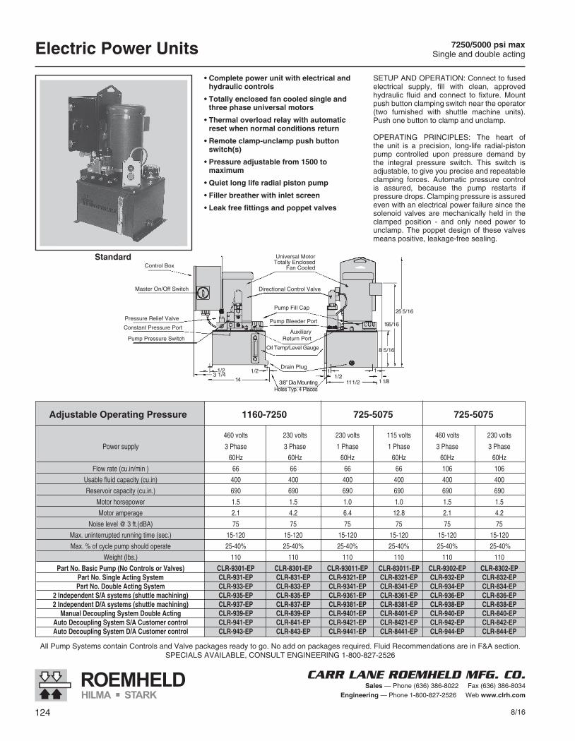
Electric Power Units 7250/5000 psi maxSingle and double acting
• Complete power unit with electrical and hydraulic controls
• Totally enclosed fan cooled single and three phase universal motors
• Thermal overload relay with automatic reset when normal conditions return
• Remote clamp-unclamp push button switch(s)
• Pressure adjustable from 1500 to maximum
• Quiet long life radial piston pump
• Filler breather with inlet screen
• Leak free fittings and poppet valves
SETUP AND OPERATION: Connect to fused electrical supply, fill with clean, approved hydraulic fluid and connect to fixture. Mount push button clamping switch near the operator (two furnished with shuttle machine units). Push one button to clamp and unclamp.
OPERATING PRINCIPLES: The heart of the unit is a precision, long-life radial-piston pump controlled upon pressure demand by the integral pressure switch. This switch is adjustable, to give you precise and repeatable clamping forces. Automatic pressure control is assured, because the pump restarts if pressure drops. Clamping pressure is assured even with an electrical power failure since the solenoid valves are mechanically held in the clamped position - and only need power to unclamp. The poppet design of these valves means positive, leakage-free sealing.
Control Box
Master On/Off Switch
Pressure Relief Valve
Constant Pressure Port
Pump Pressure Switch
Universal MotorTotally Enclosed
Fan Cooled
Directional Control Valve
Pump Fill Cap
Pump Bleeder Port
AuxiliaryReturn Port
Oil Temp/Level Gauge
Drain Plug1
1/211 1/2
1
1 1/8
8 5/16
195/16
25 5/16
14
1/23 1/4
1/2
3/8” Dia MountingHoles Typ. 4 Places
Standard
8/16 125
CARR LANE ROEMHELD MFG. CO.Sales — Phone (636) 386-8022 Fax (636) 386-8034
Engineering — Phone 1-800-827-2526 Web www.clrh.com
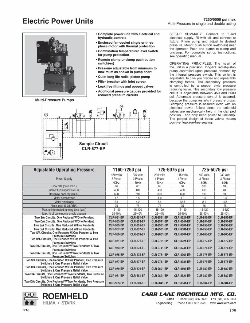
Electric Power Units 7250/5000 psi maxMulti-Pressure in single and double acting
SET-UP SUMMARY: Connect to fused electrical supply, fill with oil, and connect to fixture. Prime pump and adjust to desired pressure. Mount push button switch(es) near the operator. Push one button to clamp and unclamp. For complete set-up instructions, see operating manual.
OPERATING PRINCIPLES: The heart of the unit is a precision, long-life radial-piston pump controlled upon pressure demand by the integral pressure switch. This switch is adjustable, to give you precise and repeatable clamping forces. The secondary pressure is controlled by a poppet style pressure reducing valve. This secondary low pressure circuit is adjustable between 450 and 5500 psi. Automatic pressure control is assured, because the pump restarts if pressure drops. Clamping pressure is assured even with an electrical power failure since the solenoid valves are mechanically held in the clamped position - and only need power to unclamp. The poppet design of these valves means positive, leakage-free sealing.
• Complete power unit with electrical and hydraulic controls
• Enclosed fan-cooled single or three phase motor with thermal protection
• Combination temperature/ level switch for pump protection
• Remote clamp-unclamp push button switch(es)
• Pressure adjustable from minimum to maximum as shown in pump chart
• Quiet long life radial piston pump• Filler breather with inlet screen• Leak free fittings and poppet valves• Additional pressure gauges provided for
reduced pressure circuits
Adjustable Operating Pressure 1160-7250 psi 725-5075 psi 725-5075 psi
Power Supply460 volts 3 Phase
60Hz
230 volts 3 Phase
60Hz
230 volts 1 Phase
60Hz
115 volts 1 Phase
60Hz
460 volts 3 Phase
60Hz
230 volts 3 Phase
60HzFlow rate (cu.in./min.) 66 66 66 66 106 106
Usable fluid capacity (cu.in.) 400 400 400 400 400 400Reservoir capacity (cu.in.) 690 690 690 690 690 690
Motor horsepower 1.5 1.5 1.0 1.0 1.5 1.5Motor amperage 2.1 4.2 6.4 12.8 2.1 4.2
Nose level @ 3ft.(dBA) 75 75 75 75 75 75Max. uninterrupted running time (sec.) 15-120 15-120 15-120 15-120 15-120 15-120Max. % of cycle pump should operate 25-40% 25-40% 25-40% 25-40% 25-40% 25-40%
Two S/A Circuits, One Reduced W/One Pendent CLR-951-EP CLR-851-EP CLR-9521-EP CLR-8521-EP CLR-952-EP CLR-852-EPTwo D/A Circuits, One Reduced W/One Pendent CLR-953-EP CLR-853-EP CLR-9541-EP CLR-8541-EP CLR-954-EP CLR-854-EPTwo S/A Circuits, One Reduced W/Two Pendents CLR-955-EP CLR-855-EP CLR-9561-EP CLR-8561-EP CLR-956-EP CLR-856-EPTwo D/A Circuits, One Reduced W/Two Pendents CLR-957-EP CLR-857-EP CLR-9581-EP CLR-8581-EP CLR-958-EP CLR-858-EP
Two S/A Circuits, One Reduced W/One Pendent & TwoPressure Switches CLR-959-EP CLR-859-EP CLR-9601-EP CLR-8601-EP CLR-960-EP CLR-860-EP
Two D/A Circuits, One Reduced W/One Pendent & TwoPressure Switches
CLR-971-EP CLR-871-EP CLR-9721-EP CLR-8721-EP CLR-972-EP CLR-872-EP
Two S/A Circuits, One Reduced W/Two Pendents & TwoPressure Switches
CLR-973-EP CLR-873-EP CLR-9741-EP CLR-8741-EP CLR-974-EP CLR-874-EP
Two D/A Circuits, One Reduced W/Two Pendents & TwoPressure Switches CLR-975-EP CLR-875-EP CLR-9761-EP CLR-8761-EP CLR-976-EP CLR-876-EP
Two S/A Circuits, One Reduced W/One Pendent, Two PressureSwitches & One Pressure Relief Valve CLR-977-EP CLR-877-EP CLR-9781-EP CLR-8781-EP CLR-978-EP CLR-878-EP
Two D/A Circuits, One Reduced W/One Pendent, Two PressureSwitches & One Pressure Relief Valve CLR-979-EP CLR-879-EP CLR-9801-EP CLR-8801-EP CLR-980-EP CLR-880-EP
Two S/A Circuits, One Reduced W/Two Pendents, Two PressureSwitches & One Pressure Relief Valve CLR-981-EP CLR-881-EP CLR-9821-EP CLR-8821-EP CLR-982-EP CLR-882-EP
Two D/A Circuits, One Reduced W/Two Pendents, Two PressureSwitches & One Pressure Relief Valve CLR-983-EP CLR-883-EP CLR-9841-EP CLR-8841-EP CLR-984-EP CLR-884-EP
Multi-Pressure Pumps
Sample CircuitCLR-877-EP
126 8/16
CARR LANE ROEMHELD MFG. CO.Sales — Phone (636) 386-8022 Fax (636) 386-8034
Engineering — Phone 1-800-827-2526 Web www.clrh.com
Electric Power Units 7250/5000 psi maxSingle and double acting
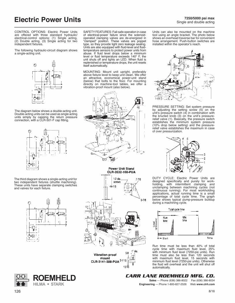
SAFETY FEATURES: Fail-safe operation in case of electrical-power failure since the solenoid-operated clamping valves are de-energized in “clamped” position. These valves are poppet type, so they provide tight zero leakage sealing. Units are also equipped with fluid-level and fluid-temperature sensors to protect power units from abuse. If fluid level drops below a minimum level or fluid temperature exceeds 140° F, the unit shuts off and lights an LED. When fluid is replenished or temperature drops, the unit resets itself automatically.
MOUNTING: Mount unit upright, preferably above fixture level to keep unit clean. We offer an attractive, economical power-unit stand (below) that bolts to the floor. For mounting directly on machine-tool tables, we offer a vibration-proof mount (also below).
PRESSURE SETTING: Set system pressure by adjusting the setting screw (5) on the unit’s pressure switch (4) in combination with the knurled knob (3) on the unit’s pressure-relief valve (1). Basically, the pressure switch establishes the minimum system pressure (10% drop below setting) and the pressure-relief valve establishes the maximum in case of over pressurization.
DUTY CYCLE: Electric Power Units are designed specifically and purely for work-holding, with intermittent clamping and un clamping between machining cycles (not continuous running). For most workholding ap plications, actual running time is a small percentage of total cycle time. The graph below shows typical pump-pressure buildup during a machining cycle.
Run time must be less than 40% of total cycle time with maximum fluid level, 25% with minimum fluid level (7250-psi units). Run time must also be less than 120 seconds with maximum fluid level, 15 seconds with minimum fluid level (7250-psi units). Otherwise the fluid will overheat and the unit will shut off automatically.
Units can also be mounted on the machine tool using an angle bracket. The photo below shows an overhead traverse bar for convenient hose arrangement. Push-button switches are installed within the operator’s reach.
CONTROL OPTIONS: Electric Power Units are offered with three standard hydraulic/ electrical-control options: (1) Single acting, (2) Double acting, (3) Single acting for two independent fixtures.
The following hydraulic-circuit diagram shows a single-acting unit.
The diagram below shows a double-acting unit. Double-acting units can be used as single acting units simply by capping the return pressure connection, with a CLR-501-F cap fitting.
The third diagram shows a single-acting unit for two independent fixtures (shuttle ma chin ing). These units have separate clamping switches and valves for each fixture.

8/16 127
CARR LANE ROEMHELD MFG. CO.Sales — Phone (636) 386-8022 Fax (636) 386-8034
Engineering — Phone 1-800-827-2526 Web www.clrh.com
Connection Examples
Electric Power Units
Two FixturesSingle Acting
(use CLR-935-EP or CLR-835-EP)
Multiple Parts Clamped IndependentlySingle Acting or Double Acting
(use any Electric Power Unit)
Single FixtureSingle Acting
(use any Electric Power Unit)
Single FixtureDouble Acting
(use CLR-933-EP or CLR-833-EP)
(see F&A section)
(see valves section)
128 8/16
CARR LANE ROEMHELD MFG. CO.Sales — Phone (636) 386-8022 Fax (636) 386-8034
Engineering — Phone 1-800-827-2526 Web www.clrh.com
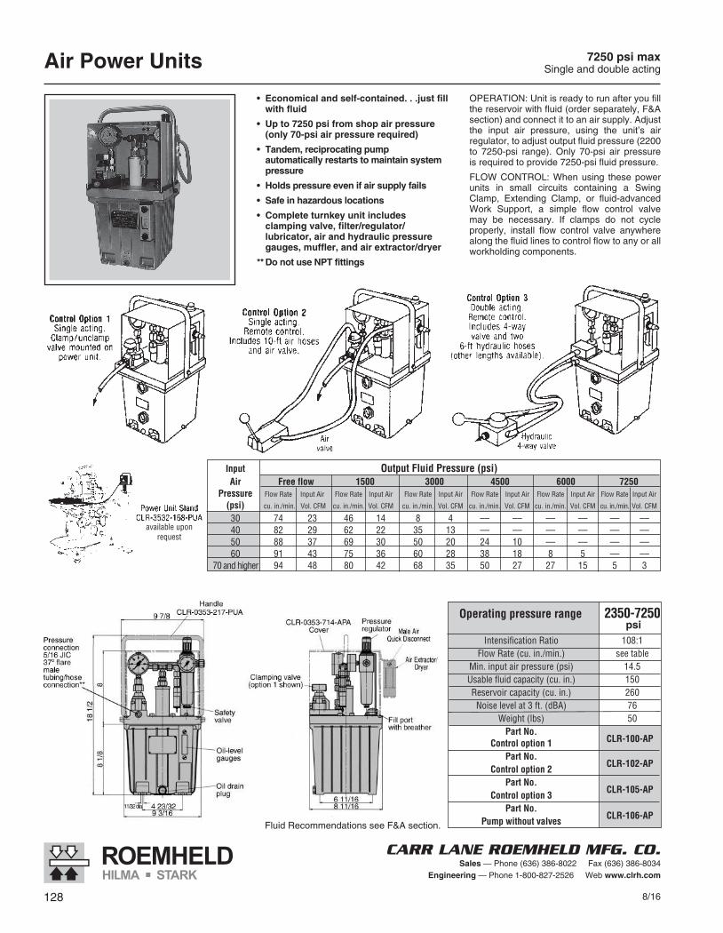
Air Power Units 7250 psi maxSingle and double acting
• Economicalandself-contained...justfillwithfluid
• Upto7250psifromshopairpressure(only70-psiairpressurerequired)
• Tandem,reciprocatingpumpautomaticallyrestartstomaintainsystempressure
• Holdspressureevenifairsupplyfails
• Safeinhazardouslocations
• Completeturnkeyunitincludesclampingvalve,filter/regulator/lubricator,airandhydraulicpressuregauges,muffler,andairextractor/dryer
**DonotuseNPTfittings
OPERATION: Unit is ready to run after you fill the reservoir with fluid (order separately, F&A section) and connect it to an air supply. Adjust the input air pressure, using the unit’s air regulator, to adjust output fluid pressure (2200 to 7250-psi range). Only 70-psi air pressure is required to provide 7250-psi fluid pressure.
FLOW CONTROL: When using these power units in small circuits containing a Swing Clamp, Extending Clamp, or fluid-advanced Work Support, a simple flow control valve may be necessary. If clamps do not cycle properly, install flow control valve anywhere along the fluid lines to control flow to any or all workholding components.
Fluid Recommendations see F&A section.
CLR-100-AP
CLR-102-AP
CLR-105-AP
CLR-106-AP
Operating pressure range 2350-7250 psi Intensification Ratio 108:1 Flow Rate (cu. in./min.) see table Min. input air pressure (psi) 14.5 Usable fluid capacity (cu. in.) 150 Reservoir capacity (cu. in.) 260 Noise level at 3 ft. (dBA) 76 Weight (lbs) 50 Part No. Control option 1 Part No. Control option 2 Part No. Control option 3 Part No. Pump without valves
Input Output Fluid Pressure (psi) Air Free flow 1500 3000 4500 6000 7250 Pressure Flow Rate Input Air Flow Rate Input Air Flow Rate Input Air Flow Rate Input Air Flow Rate Input Air Flow Rate Input Air
(psi) cu. in./min. Vol. CFM cu. in./min. Vol. CFM cu. in./min. Vol. CFM cu. in./min. Vol. CFM cu. in./min. Vol. CFM cu. in./min. Vol. CFM
30 74 23 46 14 8 4 –– –– –– –– –– –– 40 82 29 62 22 35 13 –– –– –– –– –– –– 50 88 37 69 30 50 20 24 10 –– –– –– –– 60 91 43 75 36 60 28 38 18 8 5 –– –– 70 and higher 94 48 80 42 68 35 50 27 27 15 5 3
available upon request
8/16 129
CARR LANE ROEMHELD MFG. CO.Sales — Phone (636) 386-8022 Fax (636) 386-8034
Engineering — Phone 1-800-827-2526 Web www.clrh.com
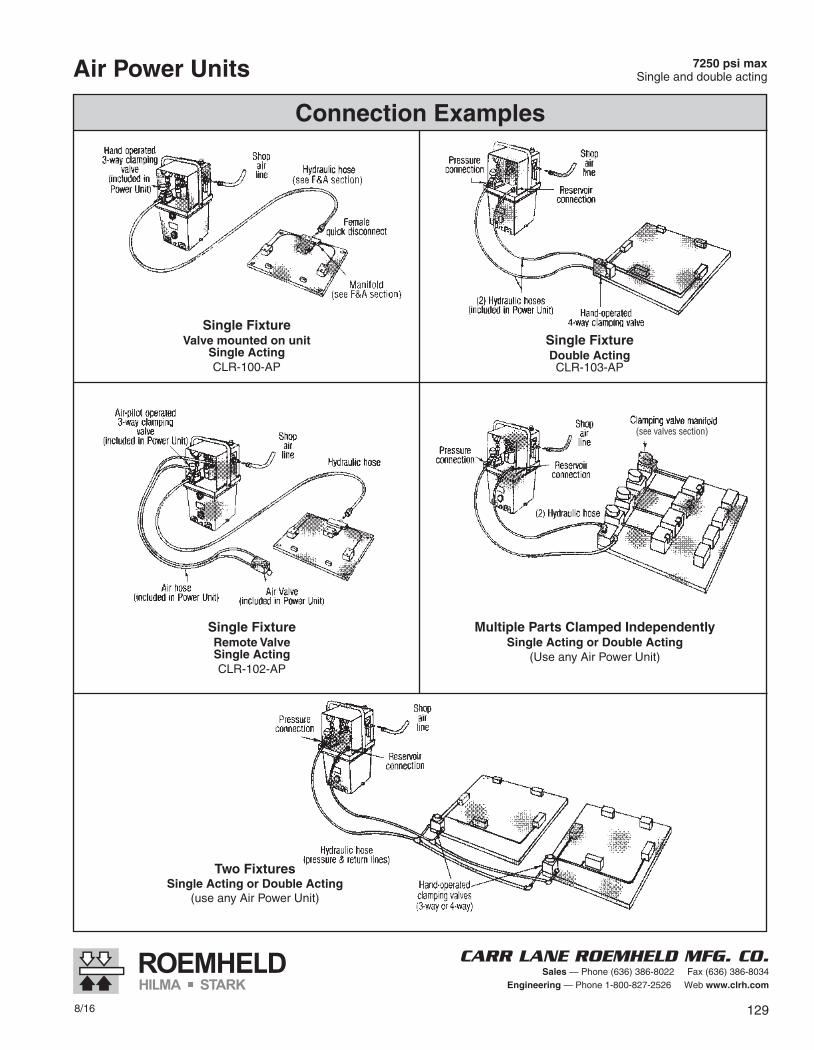
Connection Examples
Air Power Units
Single FixtureValve mounted on unit
Single ActingCLR-100-AP
Single FixtureDouble ActingCLR-103-AP
Single FixtureRemote ValveSingle ActingCLR-102-AP
Multiple Parts Clamped IndependentlySingle Acting or Double Acting
(Use any Air Power Unit)
Two FixturesSingle Acting or Double Acting
(use any Air Power Unit)
7250 psi maxSingle and double acting
(see F&A section)
(see valves section)
130 8/16
CARR LANE ROEMHELD MFG. CO.Sales — Phone (636) 386-8022 Fax (636) 386-8034
Engineering — Phone 1-800-827-2526 Web www.clrh.com
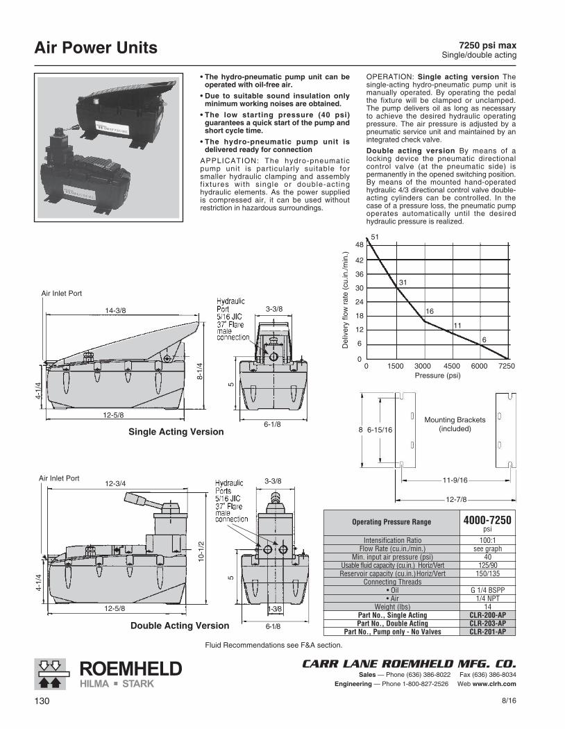
7250 psi maxSingle/double actingAir Power Units
• The hydro-pneumatic pump unit can be operated with oil-free air.
• Due to suitable sound insulation only minimum working noises are obtained.
• The low starting pressure (40 psi) guarantees a quick start of the pump and short cycle time.
• The hydro-pneumatic pump unit is delivered ready for connection
APPLICATION: The hydro-pneumatic pump unit is particularly suitable for smaller hydraulic clamping and assembly f ixtures with single or double-act ing hydraulic elements. As the power supplied is compressed air, it can be used without restriction in hazardous surroundings.
OPERATION: Single acting version The single-acting hydro-pneumatic pump unit is manually operated. By operating the pedal the fixture will be clamped or unclamped. The pump delivers oil as long as necessary to achieve the desired hydraulic operating pressure. The air pressure is adjusted by a pneumatic service unit and maintained by an integrated check valve.
Double acting version By means of a locking device the pneumatic directional control valve (at the pneumatic side) is permanently in the opened switching position. By means of the mounted hand-operated hydraulic 4/3 directional control valve double-acting cylinders can be controlled. In the case of a pressure loss, the pneumatic pump operates automatically until the desired hydraulic pressure is realized.
Del
iver
y flo
w r
ate
(cu.
in./m
in.)
48
42
36
30
24
18
12
6
0
51
31
16
11
6
0 1500 3000 4500 6000 7250Pressure (psi)
8 6-15/16
11-9/16
12-7/8
Mounting Brackets(included)
3-3/812-3/4
10-1
/2
12-5/8
4-1/
4
Double Acting Version
5
Air Inlet Port
6-1/8
1-3/8
3-3/814-3/8
12-5/8
4-1/
4
8-1/
4
Single Acting Version
5
6-1/8
Air Inlet Port
Fluid Recommendations see F&A section.
Operating Pressure Range 4000-7250psi
Intensification Ratio 100:1 Flow Rate (cu.in./min.) see graph Min. input air pressure (psi) 40 Usable fluid capacity (cu.in.) Horiz/Vert 125/90 Reservoir capacity (cu.in.)Horiz/Vert 150/135 Connecting Threads •Oil G1/4BSPP •Air 1/4NPT Weight (lbs) 14 Part No., Single Acting CLR-200-AP Part No., Double Acting CLR-203-AP Part No., Pump only - No Valves CLR-201-AP
8/16 131
CARR LANE ROEMHELD MFG. CO.Sales — Phone (636) 386-8022 Fax (636) 386-8034
Engineering — Phone 1-800-827-2526 Web www.clrh.com
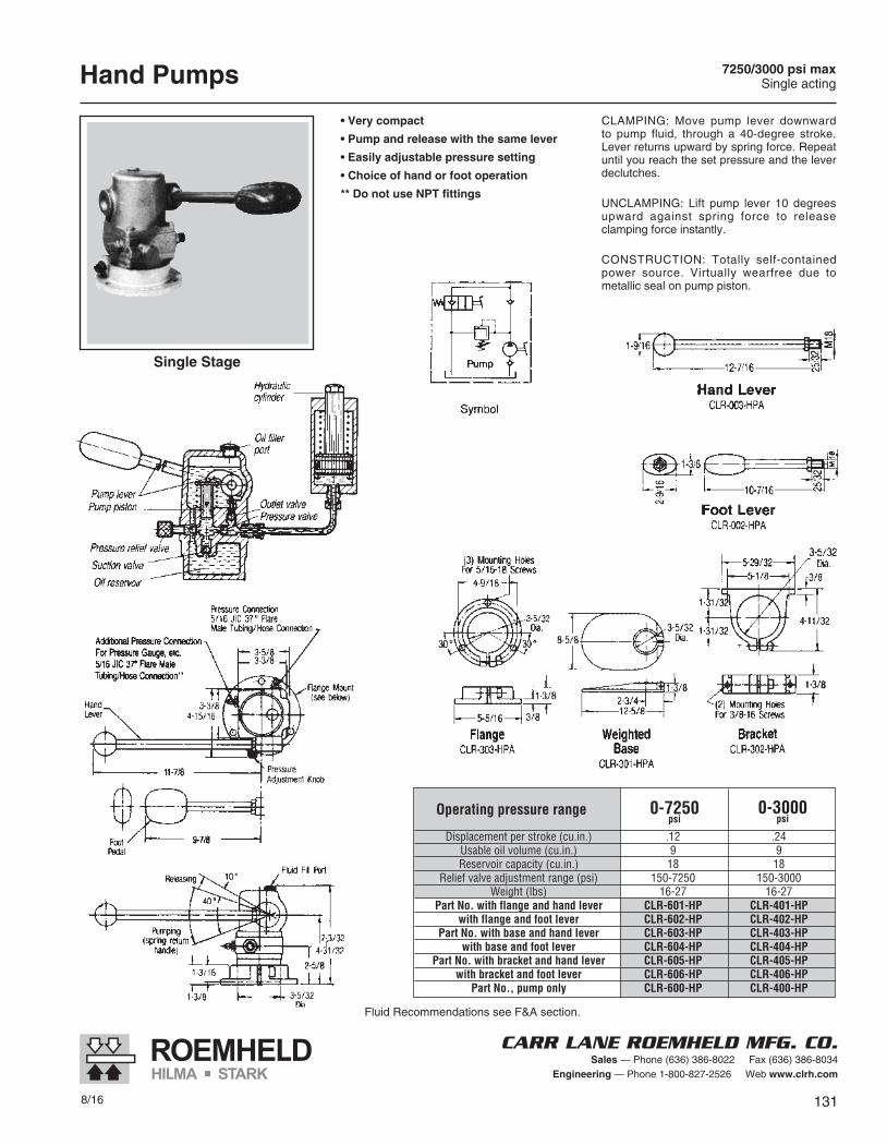
Hand Pumps 7250/3000 psi maxSingle acting
• Very compact
• Pump and release with the same lever
• Easily adjustable pressure setting
• Choice of hand or foot operation
** Do not use NPT fittings
CLAMPING: Move pump lever downward to pump fluid, through a 40-degree stroke. Lever returns upward by spring force. Repeat until you reach the set pressure and the lever declutches.
UNCLAMPING: Lift pump lever 10 degrees upward against spring force to release clamping force instantly.
CONSTRUCTION: Totally self-contained power source. Virtually wearfree due to metallic seal on pump piston.
Single Stage
Operating pressure range Displacement per stroke (cu.in.) .12 .24 Usable oil volume (cu.in.) 9 9 Reservoir capacity (cu.in.) 18 18 Relief valve adjustment range (psi) 150-7250 150-3000 Weight (lbs) 16-27 16-27 Part No. with flange and hand lever CLR-601-HP CLR-401-HP with flange and foot lever CLR-602-HP CLR-402-HP Part No. with base and hand lever CLR-603-HP CLR-403-HP with base and foot lever CLR-604-HP CLR-404-HP Part No. with bracket and hand lever CLR-605-HP CLR-405-HP with bracket and foot lever CLR-606-HP CLR-406-HP Part No., pump only CLR-600-HP CLR-400-HP
0-7250psi
0-3000psi
Fluid Recommendations see F&A section.
132 8/16
CARR LANE ROEMHELD MFG. CO.Sales — Phone (636) 386-8022 Fax (636) 386-8034
Engineering — Phone 1-800-827-2526 Web www.clrh.com
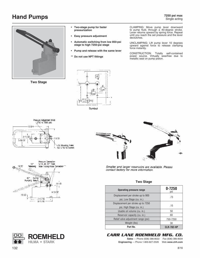
Hand Pumps 7250 psi maxSingle acting
• Two-stagepumpforfaster pressurization
• Easypressureadjustment
• Automaticswitchingfromlow850-psistagetohigh7250-psistage
• Pumpandreleasewiththesamelever
** DonotuseNPTfittings
CLAMPING: Move pump lever downward to pump fluid, through a 40-degree stroke. Lever returns upward by spring force. Repeat until you reach the set pressure and the lever declutches.
UNCLAMPING: Lift pump lever 10 degrees upward against force to release clamping force instantly.
CONSTRUCTION: Totally self-contained power source. Virtually wearfree due to metallic seal on pump piston.
TwoStage
TwoStage
0-7250psi
.73
.15
5060
750-725030
CLR-702-HP
Operating pressure range
Displacement per stroke up to 900 psi, Low Stage (cu. in.) Displacemen t per stroke up to 7250 psi, High Stage (cu. in.) Usable oil volume (cu. in.) Reservoir capacity (cu. in.) Relief valve adjustment range (psi) Weight (lbs) Part No.

8/16 133
CARR LANE ROEMHELD MFG. CO.Sales — Phone (636) 386-8022 Fax (636) 386-8034
Engineering — Phone 1-800-827-2526 Web www.clrh.com
Screw Pumps 7250 psi maxSingle acting
• Compactpressuresource
• Idealforrotarytablesorpalletswherefluidssupplylinesareimpractical
•Excellentforholdingpressurewhilefixtureistransferred
•Canbeusedinmultiplesformorefluidcapacity
•Maybeoperatedwithapowertorquewrench(non-impact)
•7250psipressurefrom38ft-lbstorque
**DonotuseNPTfittings
DESIGN CONSIDERATIONS:
1. Include a pressure gauge in the system (see F&A section).
2. All clamps and components must be leak free, so use only Roemheld products.
3. Since fluid capacity is limited, use only on small fixtures. For best results, clamps should use only 65% of total fluid capacity. Due to limited capacity, use only with smallest accumulator CLR-9606-102-PDA.
4. Systems must be bled carefully and designed to avoid air pockets. In clude a separate fill plug on the cartridge mounted version, at the high est point in the system.
5. Mount block-type Screw Pump only horizontally with fluid fill port up.
6. For safety on palletized fixtures, use a control cylinder (F&A section) with a po sition sensor on the machine.
CompactBlock Cartridge/ManifoldMounted
A body threadB Hex
Part No., compact blockPart No., manifold mounted
Part No., sealing washer
INCH1-1/2- 16
1/2CLR-900-SPCLR-901-SP
CLR-3000-843-SW
METRICA body thread
B HexPart No., compact block
Part No., manifold mountedPart No., sealing washer
M38 x 1.5 SW 13
CLR-8819-001-SPCLR-8819-101-SPCLR-3000-843-SW
Operating Pressure Range
Total fluid capacity (cu. in.)Fluid displacement per revolution (cu. in.)
Installation torque, manifold mounting (ft. lbs.)Weight (lbs)
0-7250psi
1.28.06584.0
134 8/16
CARR LANE ROEMHELD MFG. CO.Sales — Phone (636) 386-8022 Fax (636) 386-8034
Engineering — Phone 1-800-827-2526 Web www.clrh.com
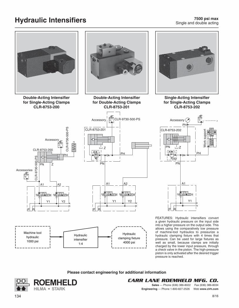
Hydraulic Intensifiers 7500 psi maxSingle and double acting
FEATURES: Hydraulic intensifiers convert a given hydraulic pressure on the input side into a higher pressure on the output side. This allows using the comparatively low pressure of machine-tool hydraulics to pressurize a hydraulic clamping fixture with 4 times that pressure. Can be used for large fixtures as well as small, because clamps are initially charged by the lower input pressure, through a check valve in the piston. The high-pressure piston is only activated after the desired trigger pressure is reached.
Please contact engineering for additional information
P R
A1
Y1
12 3
Accessory
CLR-8753-202
PH
PN
PN60
Z
PHAccessory
Wor
k su
ppor
t
P R
A1
Y1 Y2
A2
12 3
CLR
-973
0-50
0-PS
12 3
CLR
-973
0-50
0-PS
Accessory
Accessories
PN Z
CLR-8753-200PH
P R
A1
Y1 Y2
A2
12 3 CLR-9730-500-PSAccessory
CLR-8753-201
Z
PN
PH
Double-Acting Intensifierfor Single-Acting Clamps
CLR-8753-200
Double-Acting Intensifierfor Double-Acting Clamps
CLR-8753-201
Single-Acting Intensifierfor Single-Acting Clamps
CLR-8753-202
Machine toolhydraulic1000 psi
Hydraulicintensifier
1:4
Hydraulicclamping fixture
4000 psi
8/16 135
CARR LANE ROEMHELD MFG. CO.Sales — Phone (636) 386-8022 Fax (636) 386-8034
Engineering — Phone 1-800-827-2526 Web www.clrh.com
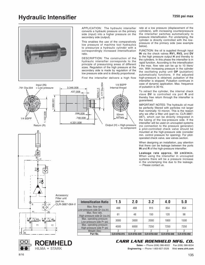
Hydraulic Intensifier 7250 psi max
APPLICATION: The hydraulic intensifier converts a hydraulic pressure on the primary side (input) into a higher pressure on the secondary side (output).
This enables the use of the comparatively low pressure of machine tool hydraulics to pressurize a hydraulic cylinder with a correspondingly increased intenisification ratio.
DESCRIPTION: The construction of the hydraulic intensifier corresponds to the principle of pressurizing areas of different sizes. Regulation of the high pressure at the secondary side is made by regulation of the low pressure side and is directly proportional.
First the intensifier delivers a high flow
rate at a low pressure (displacement of the cylinders), with increasing counterpressure the intensifier switches automatically to pressure intensification. For unclamping, the cylinder is directly controlled with the low-pressure of the primary side (see example below).
FUNCTION: the oil is supplied through input IN via the check valves RV1, RV2, and DV to the high pressure output H and thereby to the cylinders. In this phase the intensifier is in rapid function. According to the in ten sification i the max. flow rate can be up to 10 liters/min. With increasing pressure in the cylinder the oscillating pump unit OP (pulsation) automatically functions. If the adjusted high-pressure is obtained, pulsation of the intensifier is stopped. Pulsation continues in case of dynamic application. Max. frequence of pulsation is 30 Hz.
To retract the cylinder, the internal check vlave DV is controlled via port R and thereby free return through the intensifier is guaranteed.
IMPORTANT NOTES: The hydraulic oil must be perfectly filtered with particles not larger than nominally 10 micron. This is the reason why we offer a filter unit (part no. CLR-3887-087), which can be directly integrated in the tubing of the low-pressure side. If the intensifier will be used on uncoupled systems (no connection to the pressure generator) a pilot-controlled check valve should be mounted at the high-pressure side (consider min. control pressure for opening). For pilot-operated check valve, see valves section.
When designing an installation, pay attention that there can be leakage between the ports IN and R of the high-pressure intensifier.
Leakage rate approx. 50 cm3/min. When using the intensifier in uncoupled systems there will be a pressure increase in the unclamping line due to the leakage. — Please contact us.
Accessory:Filter unitpart no.CLR-3887-064-V
Intensification Ratio 1.5 2.0 3.2 4.0 5.0 Max. flow rate Low-pressure side QIN (cu.in)
488 488 915 854 854
Max. flow rate, High-pressure side QH (cu.in) 61 48 150 120 98
Max. operating pressure Low-pressure side PIN psi 3000 3000 2000 1800 1500
Max. operating pressure High-pressure side PH psi 4500 6000 7250 7250 7250
Weight (lbs) 2 2 2 2 2 Part No. CLR-8755-015 CLR-8755-O20 CLR-8755-032 CLR-8755-040 CLR-8755-050
136 8/16
CARR LANE ROEMHELD MFG. CO.Sales — Phone (636) 386-8022 Fax (636) 386-8034
Engineering — Phone 1-800-827-2526 Web www.clrh.com
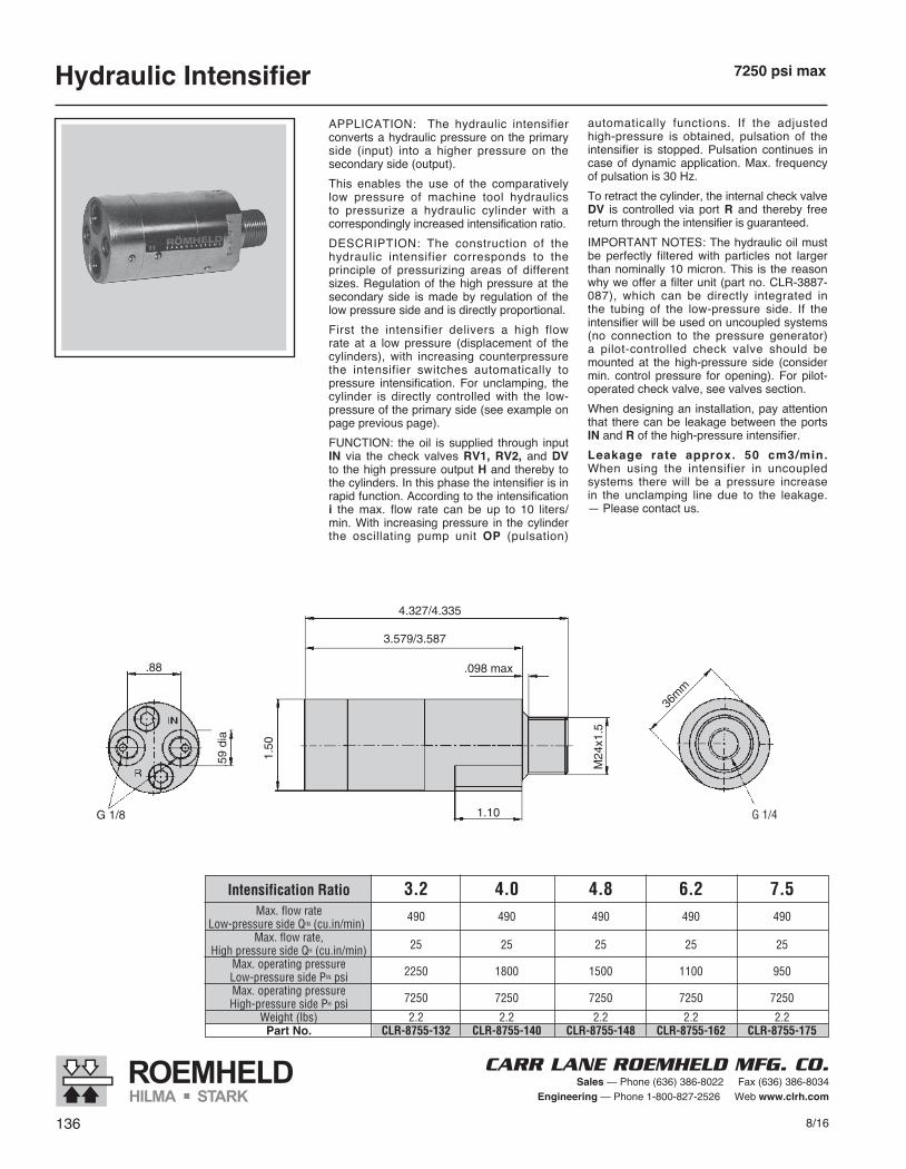
Hydraulic Intensifier 7250 psi max
APPLICATION: The hydraulic intensifier converts a hydraulic pressure on the primary side (input) into a higher pressure on the secondary side (output).This enables the use of the comparatively low pressure of machine tool hydraulics to pressurize a hydraulic cylinder with a correspondingly increased intensification ratio.DESCRIPTION: The construction of the hydraulic intensifier corresponds to the principle of pressurizing areas of different sizes. Regulation of the high pressure at the secondary side is made by regulation of the low pressure side and is directly proportional.First the intensifier delivers a high flow rate at a low pressure (displacement of the cylinders), with increasing counterpressure the intensifier switches automatically to pressure intensification. For unclamping, the cylinder is directly controlled with the low-pressure of the primary side (see example on page previous page).FUNCTION: the oil is supplied through input IN via the check valves RV1, RV2, and DV to the high pressure output H and thereby to the cylinders. In this phase the intensifier is in rapid function. According to the in ten sification i the max. flow rate can be up to 10 liters/min. With increasing pressure in the cylinder the oscillating pump unit OP (pulsation)
automatically functions. If the adjusted high-pressure is obtained, pulsation of the intensifier is stopped. Pulsation continues in case of dynamic application. Max. frequency of pulsation is 30 Hz.To retract the cylinder, the internal check valve DV is controlled via port R and thereby free return through the intensifier is guaranteed.IMPORTANT NOTES: The hydraulic oil must be perfectly filtered with particles not larger than nominally 10 micron. This is the reason why we offer a filter unit (part no. CLR-3887-087), which can be directly integrated in the tubing of the low-pressure side. If the intensifier will be used on uncoupled systems (no connection to the pressure generator) a pilot-controlled check valve should be mounted at the high-pressure side (consider min. control pressure for opening). For pilot-operated check valve, see valves section.When designing an installation, pay attention that there can be leakage between the ports IN and R of the high-pressure intensifier.Leakage rate approx. 50 cm3/min. When using the intensifier in uncoupled systems there will be a pressure increase in the unclamping line due to the leakage. — Please contact us.
Intensification Ratio 3.2 4.0 4.8 6.2 7.5 Max. flow rate Low-pressure side QIN (cu.in/min)
490 490 490 490 490
Max. flow rate, High pressure side QH (cu.in/min) 25 25 25 25 25
Max. operating pressure Low-pressure side PIN psi 2250 1800 1500 1100 950
Max. operating pressure High-pressure side PH psi 7250 7250 7250 7250 7250
Weight (lbs) 2.2 2.2 2.2 2.2 2.2 Part No. CLR-8755-132 CLR-8755-140 CLR-8755-148 CLR-8755-162 CLR-8755-175
G 1/4
OUR STORYIn 1982 an independent joint venture was established to marry the proven product expertise of Roemheld with the marketing know-how and distribution network of Carr Lane Manufacturing. This partnership now offers to the American manufacturer the complete benefits of the finest in international power workholding combined with the best in local service and support.
After initial tests by many companies, both small and large, the word had spread confirming the quality and reliability obtained when using Roemheld Power Workholding products.
We invite you to review this catalog in depth and to call us with any questions about your applications. We at Carr Lane Roemheld welcome the opportunity to help you manufacture your quality product in the most productive way possible — with the world’s most dependable workholding equipment.
Founded in 1952 in St. Louis, Missouri by Earl Walker to make standardized tooling components, Carr Lane Manufacturing has grown, through constant innovation, to become the foremost supplier to the American Machine Tool Industry. Now the most complete line available, Carr Lane Mfg. offers Jig and Fixture Components, Toggle Clamps, Hoist Rings, Alignment Pins, Drill Bushings, Spring Plungers, and Modular Fixturing. Setting the standard for American Tool Engineers, Carr Lane Manufacturing’s catalog is recognized as the engineer’s tooling reference.
Drawing upon a centuries-old tradition of German craftsmanship, metalworking was already well established in Laubach, Germany when the Roemheld family began to manage operations in 1870. Development of the hydraulic workholding components began in the early 1960’s and soon grew to dominate the European market.
Today, Roemheld GmbH is by far the world leader in this productivity-enhancing technology, offering a tremendous range of types and sizes of superior design and the highest quality.
SUCCESSGUARANTEED
Carr Lane Roemheld knows your power workholding system needs to be of the highest quality.
That’s why, if you work with us, you’ll get the best system, and top quality results.
We stand behind our products, and provide you with the excellent service you need to remain competitive in today’s manufacturing environment.
Work Supports
VisesPower
Sources
Fittings &Accessories
BlockCylinders
Swing Clamps
Concentric Clamping Elements
Extending ClampsPush
Clamps
Fenton, MO 63026(636) 386-8022
Find out theadvantages of ourQuality Guarantee
when you work with us!
Locking Piston
Cylinders
Valves
Fenton, MO 63026(636) 386-8022
REDUCE SET-UP AND DOWNTIME!
For Zero Point Mounting, See Pages 114-116
Zero Point Mounting System for Quick Change FixturingThis comprehensive system utilizes clamping components and insertion nipples, which provide an immediate zero point orientation.• Reduce set up time by as much as 90%
with zero point mounting• Existing fixtures can be easily adapted• Highly accurate positioning and
repeatability• Increased productivity• Fast payback• Set-up times slashed• Fixture life extended
Use in Conjunction with the Zero Point Mounting System for Faster, More Accurate Fixture Set Ups
PRECISION MACHINE VISES INCREASE PRODUCTIVITY
For Machine Vises,See Pages 94-111
927 Horan Drive n Fenton, MO 63026Phone (636) 386-8022 n Fax (636) 386-8034
Free Engineering Support 1-800-827-2526www.carrlaneroemheld.com
Connect with us: n n n
PW-0816
CARR
LANE
ROEMHELD
MFG
CO
PW
8n
2016
COPYRIGHT © 2016 CARR LANE ROEMHELD MANUFACTURING CO. 16092-0816 PRINTED IN U.S.A.
Authorized Distributor:
Power Workholding n Precision Vises n Zero Point Mounting n Assembly and Handling
PowerWorkholding