c-arm fluoroscopic and spot-film systems - u s food and drug
TRANSCRIPT
PART X
C-ARMFLUOROSCOPIC
ANDSPOT-FILMSYSTEMS
FORM FD 3260
REPRINTEDAPRIL 2000

PART X CF-1 4/1/2000
ROUTINE COMPLIANCE TESTING
C-ARM FLUOROSCOPES
(Test Procedure CFA - Use Form FDA 3260)
1.0 GENERAL GUIDANCE
1.1 This procedure is applicable to both mobile and stationary C-arm fluoroscopic x-raysystems--with or without a spot-film device. A C-arm fluoroscope is a system wherethe SID is fixed using a "C" or "U" arm and the spot-film device does not provide fortwo on one or four on one formats. Variable SID systems are not compatible withthis procedure.
1.2 When a step or entire section of the procedure does not apply to the system beingtested, simply pass over that step or section and continue. If passing over or sectionmeans that some portion of the Field Test Record will not be completed, enter an "*"in the first column of each inapplicable item in that portion of the Record.
NOTE: If multiple indicators are provided for a single parameter(e.g., kVp, etc.) but the indicators do not agree with one another,choose the indicator (1) associated with a certified component and(2) most commonly used. Note in the REMARKS that theseindicators so not agree, and estimate the amount of discrepancy.
2.0 PRETEST CHECKLIST
2.1 Turn on the main power to the x-ray system.
2.2 if not already completed, complete the General Information Field Test Record. Enterthe field test serial number, which appears preprinted on the General InformationField Test Record in the appropriate block on each page of the C-Arm FluoroscopeField Test Record.
2.3 Verify that the assemblers' reports, FD 2579's, are correctly prepared. If they arenot, write in the correct information above the incorrect information.
2.4 Enter the code for the test procedure at item 1.
2.5 Record the system type (mobile or stationary) in item 2.
2.6 Determine from the ID label or from the installation date whether the BLD wasmanufactured after 5/22/79. Record at item 3.
2.7 Examine the control panel and the BLD to determine if collimator shutter controls areprovided. If shutter blades can be continuously varied from the maximum to theminimum field size record a "2" at item 4. If, however, beam limiting is achieved byuse of fixed apertures or cones, record a "1" at item 4.
2.8 Indicate the certification status of each component making up the system at item 5.
PART X CF-2 4/1/2000
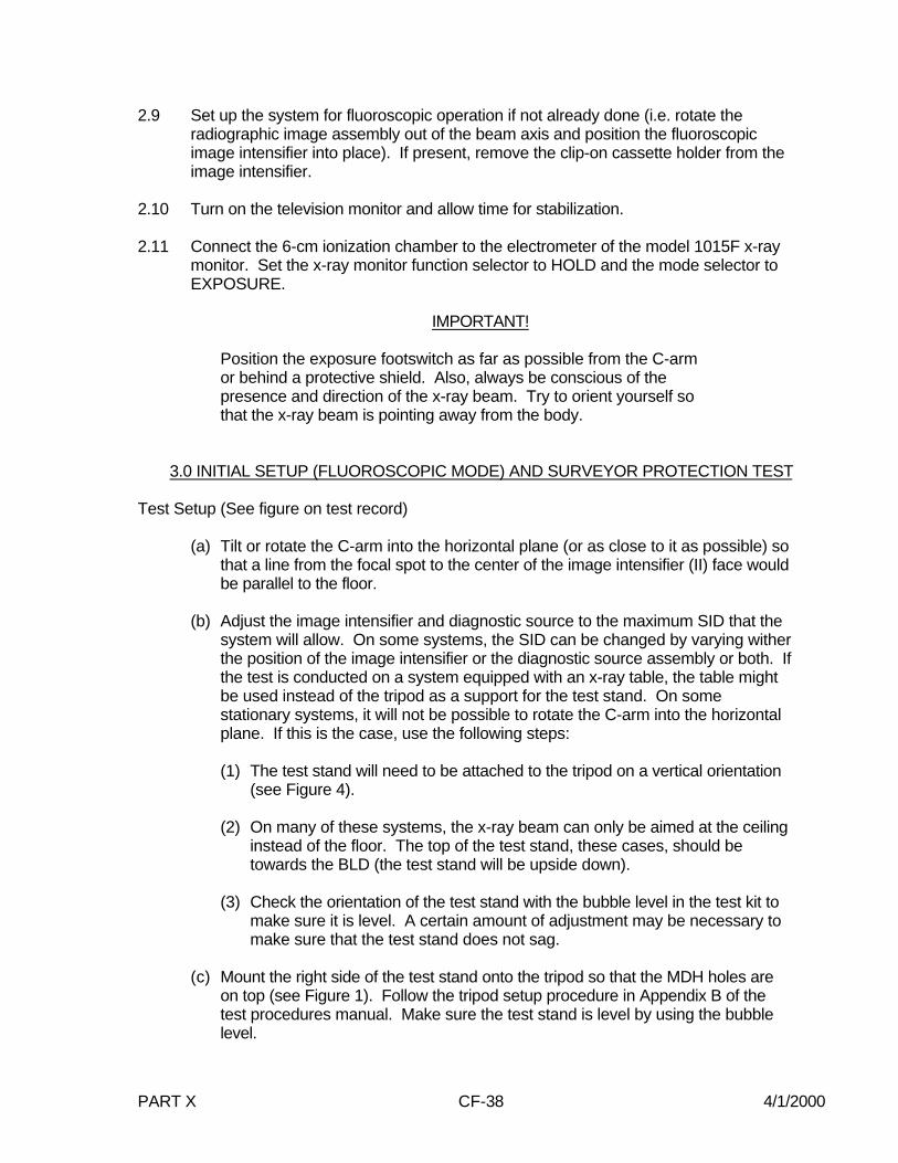
2.9 If present, remove the clip-on cassette holder form the image intensifier.
2.10 Turn on the television monitor and allow time for stabilization.
2.11 Connect the 6-cm3 ionization chamber to the electrometer of the model 1015F x-raymonitor. Set the x-ray monitor function selector to HOLD and the mode selector toEXPOSURE.
IMPORTANT!
Position the exposure floor-switch as far as possible from the C-armor behind a protective shield. Also, always be conscious of thepresence and direction of the x-ray beam. Try to orient yourself sothat the x-ray beam is pointing away from the body.
3.0 INITIAL SETUP (FLUOROSCOPIC MODE) AND SURVEYOR PROTECTION TEST
Test Setup (See figure on test record)
(a) Tilt or rotate the C-ram into the horizontal plane (or as close to it as possible) sothat a line from the center of the image intensifier (II) face would be parallel to thefloor.
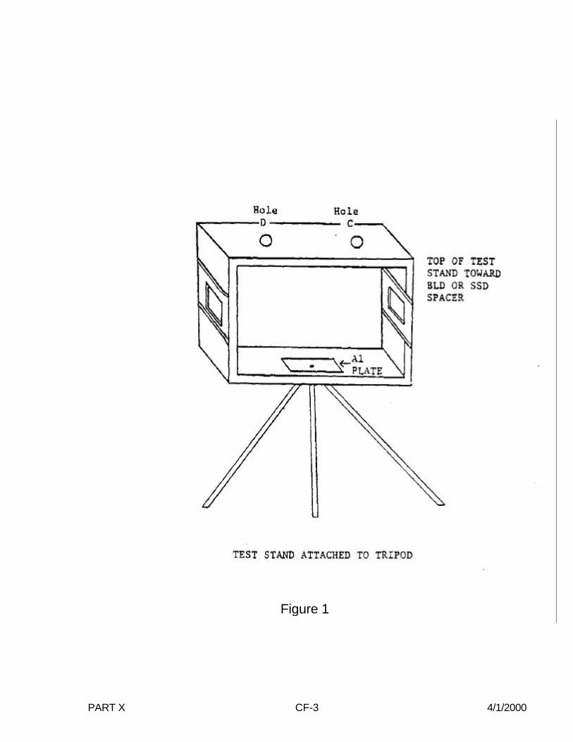
(b) Mount the right side of the test stand onto the tripod so that the MDH holes areon top (see Figure 1). Follow the tripod setup procedure in Appendix B of thetest procedures manual, except that the stand need not be leveled using thebubble level.
(c) Measure the diameter of the image intensifier housing before positioning the teststand against the image intensifier. Record at item 27.
(d) 9" Image Intensifier: Move the tripod toward the BLD until the test stand top isapproximately centered on and about 1-inch from the face of the BLD or SSDspacer. The bottom opening in the test stand should be centered over theimage intensifier face.
6" Image Intensifier: Move the tripod so that the test stand bottom is against theface of the II. Adjust the tripod height and tilt until the bottom opening in the teststand is flush against and centered on the face of the image intensifier.
(e) Center (and tape) 0.1 inches of copper (on slot 7 of the test stand). (See Figure2, modification of the test stand).
(f) Insert the slide assembly, grid side toward the BLD, into slot 6 of the test stand.
(g) Insert the 6-cm ionization chamber through the upper mounting hole (C) of thetest stand.
PART X CF-3 4/1/2000
Figure 1

PART X CF-4 4/1/2000
Figure 2

PART X CF-5 4/1/2000
TEST PROCEDURE
3.1 Select the largest cone or aperture that will still permit fluoroscopy, or if a steplessBLD is provided, fully open the shutters.
3.2 Select fluoroscopic technique factors of approximately 90 kVp and 2mA, and set thecumulative fluoro timer to its maximum setting.
3.3 Using the GM survey meter, make several short exposures and scan the work area. Note the greatest GM meter deflection. Refer to page GM-1 for instructions on theproper use of the GM meter.
NOTE: The GM meter is a sensitive instrument, but is extremelyenergy dependent. It is intended as a qualitative indication. Anyquantitative measurements of radiation exposure should be madeusing the Model 1015F x-ray monitor with the 100-cm2 ionizationchamber. The purpose of this test is to determine the radiationexposure level at any area occupied by the surveyor duringfluoroscopic exposures.
3.4 If the GM meter indication is greater than 5 for the Model 251B Survey Meter or 150for the TBM-1 Ratemeter, make follow-up measurements with the 100-cm2ionization chamber. If these follow-up measurements exceed 50 mR/hr, takeprecautions such as wearing a lead apron, standing behind a lead screen, standingaway from the system and the primary x-ray beam, etc. while making exposures. Tel the user what you found including the exposure rate and the conditions underwhich it was obtained. Explain that this is not a noncompliance with the standard butthat the measurement is taken so that the surveyor can take adequate protectivemeasures during the survey depending on the scattered radiation. Tell the user youare giving him this information is case he/she was not aware of the scatter radiationlevels under the conditions measured so that he/she can consider it as part of theirtotal radiation safety program. Enter in the REMARKS, the observed exposure rateand the conditions under which the excessive radiation rate was obtained, and thencontinue to the next page (step 3.5).
3.5 If the GM meter indication is less than 15 for the Model 251B or less than 150 for theTBM, record "N" in item 6.
3.6 Is there a warning label present on the control panel containing the main powerswitch as prescribed in 21 CFR 1020.30(j)? Record at item 7.
4.0 FLUOROSCOPIC X-RAY FIELD/IMAGE RECEPTOR ALIGNMENT
Test Setup
Same as the initial setup.
Test Procedure
4.1 Either the MANUAL or AUTO brightness control modes may be used. Make an

PART X CF-6 4/1/2000
exposure and observe the slide assembly grid image on the TV monitor. Adjust thebrightness control or the technique factors until a good quality image of the grid isobtained.
4.2 Verify that the grid is approximately centered on the TV monitor. If it is not, slightlymove the tripod with the x-ray beam off until approximate centering is obtained.
4.3 Set the x-ray monitor mode selector to EXPOSURE and the function selector toMEASURE. Leakage on the instrument should not exceed 4 mR in one minute. If itdoes, the instrument may be defective and you should contact CDRH for guidance.
4.4 Verify that the BLD is still fully open.
4.5 Insert a plastic cassette containing a sheet of direct-print paper into the slideassembly at slot 6.
4.6 If testing in a non-magnification mode, record at items 8-15. If testing in a dual-fieldtype image intensifier (e.g., one having 6" and 9" modes of operation), select themode of greatest magnification (e.g., the 6" mode). However, do not select anymode (e.g., a 4" mode) that will not allow the dimensions of the grid to be read. Ifthere is no magnification mode leave items 16-23 blank.
4.7 Make an exposure and read the dimensions of the grid that are visible at each edge.
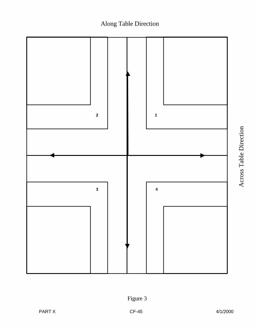
NOTE: See lines 1/4, 2/1, 3/2, and 4/3 of Figure 3. For futurereference, observe that 1/4 passes between the slide assemblyquadrant numbers 1 and 4, etc., and each small division of the gridrepresents 0.1 inches.
4.8 Record the value in order from 1/4 to 4/3 at items 8 through 11.
4.9 If the accumulated exposure is 4 R or greater, the direct-print paper should provide asatisfactory image. Make any additional exposure required to obtain a total of 4R.
4.10 Remove the cassette from the slide assembly and develop the direct-print paper byexposure to fluorescent light. (Refer to page LINA-1 for proper developmenttechnique.)
4.11 Measure to the nearest millimeter the distance from the center of the grid to the edgeof the image along each of the four lines 1/4 through 4/3.
NOTE: Again observe that 1/4 passes between the slide assemblyquadrant numbers 1 and 4, etc.
4.12 Record the values in order form 1/4 to 4/3 at items 12 through 15.
4.13 Insert a plastic cassette containing a sheet of direct-print paper into the slideassembly.

PART X CF-7 4/1/2000
12
3 4
Figure 3
Along Table Direction
Acr
oss
Tab
le D
irec
tion

PART X CF-8 4/1/2000
4.14 Repeat steps 4.7 through 4.12 for the magnification mode and record the data atitems 16 through 23.
4.15 Record the shape of the visible area at item 24.
4.16 Tube potential and current must be continuously indicated during exposure but notnecessarily at the operator's position. Record at item 25.
4.17 Verify that the maximum setting for the fluoro timer is five minutes or less. Record atitem 26.
5.0 PRIMARY PROTECTIVE BARRIER/X-RAY FIELD SIZE COMPARISON
5.1 Measure to the nearest millimeter the distance from the face of the image intensifierto the base of the test stand. Record at item 28. When bottom of test stand is flushagainst the image intensifier (setup for 6" image intensifier) record 00.0 at item 28.
6.0 MINIMUM FLUORO X-RAY FIELD SIZE
Test Setup
Same as the initial setup.
Test Procedure
6.1 Select the smallest BLD aperture or cone. If a stepless collimator is provided, closethe collimator completely and make a short exposure to see if any visible area canbe observed. If none is observed, skip the rest of this procedure and record "00.0" atitems 29 and 30 and an asterisk at item 31. If a visible area is observed, proceedwith step 6.2.
6.2 Insert a plastic cassette containing a sheet of direct-print paper into the slideassembly and insert slide assembly into slot 6.
6.3 Make an exposure to obtain at least 1.5 R to the ionization chamber.
6.4 Remove the cassette from the slide assembly and develop the direct-print paper byexposure to fluorescent light. (Refer to page LINA-1 for proper developmenttechnique.)
6.5 Measure to the nearest millimeter the length and width of the x-ray field image. Record at items 29 and 30. If the field image is circular, record the diameter twice atitems 29 and 30.
6.6 Record the x-ray field image shape at item 31.

PART X CF-9 4/1/2000
Fluoroscopic Technique Factor Control Type
Are the fluoroscopic technique factors manually controlled, automatically controlled,or are both manual and automatic fluoroscopic technique factor controls provided? Record at item 32. It may be necessary to refer to the Users Manual for an exactanswer to this question.
7.0 ENTRANCE EXPOSURE RATE - MANUAL MODE
Test Setup (See figure on test record.)
(a) Insert the focal spot assembly, brass strips toward BLD, into slot 1 of the teststand.
(b) Move the test stand until it is against the image intensifier.
Test Procedure
7.1 Insert a plastic cassette containing a sheet of direct-print paper into the slideassembly.
7.2 Set the fluoroscopic technique factor control mode to "Manual." To check the"Manual" mode insert additional copper in the beam. Observe the exposure rate withand without the additional copper. If the system is in "Manual" mode, exposure ratesin each case should be about the same. Remove any additional copper after thischeck.
7.3 Some systems do not yield their maximum entrance exposure rate at maximumtube potential or tube current; therefore, check the exposure rate at various kVp andmA settings to establish worst case technique factors. Set the x-ray monitor modeselector to EXPOSURE RATE. While making an exposure, vary the kVp and mAsettings to maximize the electrometer reading. Record the worst-case kVp at items33 and 34, respectively. Record the maximum exposure rate at item 35.
NOTE: Since the MDH 1015F provides an indication of the averageexposure rate every 1.2 seconds, the kV and mA settings must bevaried slowly to maximize the electrometer reading.
7.4 7.4 If means to activate a high-level control are provided, make an exposure. Notethe exposure rate. While making an exposure, activate the high-level control. Is ahigh-level control present in the manual mode? Record at item 36. Vary the kVp andmA settings to maximize the electrometer reading. . Use the following format:
7.4 HLC MODE: _______ kVp ______ mA _________ R/min
NOTE: Since on some systems the hookup of a high-level control isa user option, means to activate a high-level control (e.g., button ordouble detent foot switch) may be present but not hooked up. Therefore, to determine the presence or absence of such a control,

PART X CF-10 4/1/2000
a radiation exposure rate check must be made.
Special means of activation are required for high-level control, other than thatrequired to activate normal fluoroscopy. Also, continuous manual pressure must beapplied for the operation of the high-level control. This means that fluoroscopicoperation cannot be "locked" in the high-level control mode.
7.5 If the high-level exceeds the low-levels rate, record “y” in item 36. Otherwise, record“n” in item 36.
7.5 Is a continuous audible signal provided upon activation of the high-level control? Record at item 37. If a high-level control is not present, record "X" at item 37. Ifspecial means of activation or continuous manual pressure are not provided for thehigh-level control, explain the operation of the high-level control in the REMARKSsection.
NOTE: For x-ray controls manufactured after May19, 1995,the EER requirements donot apply to the recording of fluoroscopic images when operating in a pulsed mode. In addition, the recording mode is not considered high-level control and therefore, noaudible signal is required. The Center is looking into the record mode uses andwould need manufacturer justification for any unit that could operate only in a recordmode.
8.0 ENTRANCE EXPOSURE RATE - AUTOMATIC MODE
Test Setup
Same as manual mode except: Center a 1/8 inch thick lead sheet over the 0.1 inches ofcopper and tape into place.
8.1 Set the fluoroscopic technique factor control to "Automatic" and any "AutomaticBrightness Control" for maximum brightness. The "Automatic mode may bechecked by observing the exposure rate with and without the 1/8-inch lead sheet inthe beam. If the system is in "Automatic" and the kVp and mA are not at theirmaximum values, the exposure rate should be higher with the lead in the beam.
NOTE: The three variables that can be controlled by an automaticbrightness control unit are the kVp, the mA, and the width of the x-raypulses in systems with variable pulse width. A determination of thevariable controlled on the system is needed to ensure themeasurement of the maximum EER. Consult the User Manual for adescription of the automatic brightness control.
Set the x-ray monitor mode selector to EXPOSURE RATE. While making anexposure, vary the kVp and/or mA settings to obtain the maximum electrometerreading. Record the indicated tube potential and the tube current at items 38 and 39,respectively, and the exposure rate at item 40.

PART X CF-11 4/1/2000
If means to activate a high-level control are provided, make an exposure. Note theexposure rate. While making an exposure, activate the high-level control. Is a high-level control present in the manual mode? Record at item 41. Vary the kVp and mAsettings to maximize the electrometer reading. Record the high-level exposure ratein the Remarks using the following format.
8.1 HLC MODE: _______ kVp ______ mA _________ R/min
NOTE: Since on some systems the hookup of a high-level control isa user option, means to activate a high-level control (e.g., button ordouble detent foot switch) may be present but not hooked up. Therefore, to determine the presence or absence of such a control,a radiation exposure rate check must be made.
Special means of activation are required for high-level controls, other than thatrequired to activate normal fluoroscopy. Also, continuous manual pressure must beapplied for the operation of the high-level control. This means that fluoroscopicoperation cannot be "locked" in the high-level control mode.
8.2 If the high-level exceeds the low-level rate, record “y” in item 41. Otherwise, record“n” in item 41.
8.3 Is a continuous signal provided upon activation of the high-level control? Record atitem 42. If a high-level control is not present, record "X" at item 42. If special meansof activation or continuous manual pressure are not provided for the high-levelcontrol explain the operation of the high control in the REMARKS section.
NOTE: For x-ray controls manufactured after May19, 1995,the EER requirements donot apply to the recording of fluoroscopic images when operating in a pulsed mode. In addition, the recording mode is not considered high-level control and therefore, noaudible signal is required. The Center is looking into the record mode uses andwould need manufacturer justification for any unit that could operate only in a recordmode.
9.0 SID AND MINIMUM SSD
Test Setup
Same as Entrance Exposure Rate.
Test Procedure
9.1 An exposure of at least 4.5 R to the ionization chamber is required to obtain a goodimage of the focal-spot strips. Estimate the cumulative exposure delivered duringentrance exposure rate measurement. If necessary, switch the x-ray monitor modeselector to EXPOSURE and deliver the required additional exposure.
9.2 Measure to the nearest millimeter the distance from the face of the source-skindistance (SSD) spacer (or from the face of the BLD if a spacer is not present) to thetop of the brass strips. Record at item 43.

PART X CF-12 4/1/2000
9.3 Remove the cassette from the slide assembly and develop the direct-print paper byexposure to fluorescent light. (Refer to page LINA-1 for proper developmenttechnique.)
9.4 Measure to the nearest millimeter the minimum separation of the outside edges ofthe focal-spot strip images. Record at item 44.
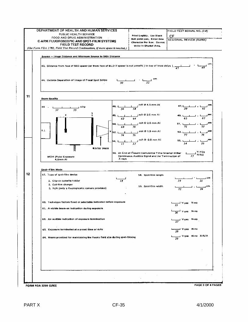
10.0 BEAM QUALITY
Test Setup (See figure on test record)
(a) Remove the focal-spot strips and lead and insert the beam-defining assembly,lead side toward BLD, in slot 1 of the test stand.
(b) Move the 6 cm3 ionization chamber to the lower mounting hold (D) of the teststand.
(c) Place 4.5 mm aluminum on the beam defining assembly in slot 1.
(d) Remove the slide assembly from the test stand.
Test Procedure
10.1 (a) If the system has only an automatic mode of operation, go directly to step 10.5.
(b) If the system has a manual fluoroscopic technique factor control mode, selectthis manual mode.
MANUAL MODE
10.2 Set the tube potential to a commonly used value above 70 kV and the tube current toat least 2.0 mA. Record the kVp at item 45.
10.3 Five exposures are required determination. With the x-ray monitor mode selector inPULSE EXPOSURE, reset the x-ray monitor by switching the function selector toHOLD and back to MEASURE. The display should indicate -0.00. Make anexposure at the selected kVp.
Record the exposure reading in item 46. Switch the function selector to pulseduration and record the time reading at item 47. Reset the x-ray monitor after theexposure by switching the function selector to HOLD and then back to MEASURE.
NOTE: If a time measurement has not been obtained or appearserroneous, the exposure rate may be too low to trigger the MDHinstrument. For this situation, the mA and/or kVp must be increased. If kVp is changed, the kVp recorded at item 45 must also bechanged.
10.4 Remove aluminum to obtain totals of 3.5, 2.5, 1.5, 0.0 millimeters on top of the beamdefining assembly. For each total, make an exposure and time at items 48 through
PART X CF-13 4/1/2000
55. Remember to reset the x-ray monitor between each exposure. Skip to 10.7.
AUTOMATIC MODE ONLY
10.5 Five exposures are required for the beam quality determination. With the x-raymonitor mode selector in PULSE EXPOSURE, reset the x-ray monitor by switchingthe function selector to HOLD and back to MEASURE. The display should indicate -0.00. Make an exposure at the selected kVp. Record the exposure reading at item46. Switch the function selector to PULSE DURATION and record the time readingat item 47.
NOTE: If a time measurement has not been obtained or appearserroneous, the exposure rate may be too low to trigger the MDHinstrument. For this situation, the mA and/or kVp must be increased. If kVp is changed, the kVp recorded at item 45 must also bechanged.
10.6 Move the aluminum from slot 1 of the test stand (toward the BLD) to slot 7 (towardthe II) so that the totals of 3.5, 2.5, 1.5, and 0.0 millimeters are left on the top of thebeam defining assembly. For each total of aluminum make an exposure asdescribed in 10.5 while RESETTING THE X-RAY MONITOR each time betweenexposures. Record the exposure and time at items 48 through 55, respectively.
10.7 Set the cumulative fluoro timer to a very short time interval, only a few seconds ifpossible, and make an exposure of duration greater than the preset time interval. Atthe end of the preset interval, does either a continuous audible signal indicate theend of the interval and/or is x-ray production terminated? Record at item 56.
11.0 RADIOGRAPHIC MODE
11.1 A radiographic mode is normally available on C-arm fluoroscopes. Usually, but notalways, the radiographic images are recorded on a spot-film device (a clip-on holderor a cut-film changer). Occasionally, a fluorographic camera is provided (e.g., a 105mm camera) for recording images off the output phosphor of the image intensifier. Such a camera is not a spot-film device. Indicate at item 57 the type of spot-filmdevice provided. If only a fluorographic camera is provided, continuation of thissection of the test procedure is not appropriate.
11.2 Record the dimensions of the spot-film image receptor or the cut-film nominal sizeat items 58 and 59.
11.3 If both Manual and Automatic (phototimed) exposure modes are provided, select themost commonly used mode of operation.
11.4 Set the tube potential to a value commonly used. Record at item 67.
11.5 Automatic:
(a) If testing in the phototimed mode, record an "*" in the first column of any of item67 which is not preindicated.
11.6 Manual:

PART X CF-14 4/1/2000
(a) If independently selectable, choose values of tube current and exposure time,and record at item 67.
(b) If only the mAs is selectable, choose a value commonly used and record at item67.
11.7 Is the system single-phase or three-phase? Record at item 66.
NOTE: Using one or more of the following methods, determinewhether the system is single-phase or three-phase.
(1) Consult the user to the information provided to him by the high voltagegenerator manufacturer.
(2) Check the identification plate to see if the manufacturer has listed the phaseof the system along with other electrical characteristics.
(3) Observe the time settings on the control panel. Single-phase timer settingsare usually expressed as common fraction multiples of 1/120 second, whilethree-phase usually have timer settings expressed as decimal fractions.
If the system is single-phase, set the x-ray Monitor thumbwheel switch to0.2, and record at item 65.
If the system is three-phase, set the x-ray Monitor thumbwheel switch to"0.5," and record at item 65.
11.8 Set the x-ray monitor mode selector switch to PULSE EXPOSURE.
11.9 If a clip-on cassette holder is provided, mount it over the face of the image intensifier. Insert an empty cassette into the cassette holder.
11.10 On some systems, a rad-fluoro mode selector switch is provided on the controlpanel. If this is the case, switch to the radiographic mode.
*It must be possible to maintain the fluoro field size during spot-filming. The user, athis option, may select automatic full coverage of the spot-film--but there must be anoption on the control panel. A system design that always provides for automatic fullcoverage of the spot-film is noncompliance. Record at item 64.
12.0 REPRODUCIBILITY & LINEARITY
Test Setup (See figure on test record)
(a) Remove the beam defining assembly from slot 1.
(b) Move the 6 cm3 ionization chamber to the upper mounting hole (C) of the teststand.
(c) Center a plastic cassette containing a sheet of direct-print paper on top of the

PART X CF-15 4/1/2000
test stand and tape on place.
Test Procedure
12.1 (a) If both "manual" and "automatic" controls are provided for exposure termination,select the mode of operation most commonly used and complete steps 12.2and 12.12.
(b) If the system has only an automatic technique factor control mode, go directly to12.13.
12.2 Adjust the BLD for full coverage of the spot-film.
MANUAL MODE
12.3 Set the x-ray monitor mode selector to PULSE EXPOSURE. Reset the x-raymonitor mode selector to PULSE EXPOSURE. Without changing the techniquefactors make an exposure. Do not record the resultant reading.
12.4 Without changing technique factors or the x-ray monitor settings, make an additionalexposure. The reading will now have no minus sign present. Record this reading atitem 69. Switch the mode selector back to PULSE EXPOSURE.
12.5 Repeat step 12.4 for three additional exposures, with the exposure readings beingrecorded at items 70, 72, and 74 and the time readings being recorded at items 71,73, and 75. Do not reset the x-ray monitor between exposures. All variable controlsfor technique factors shall be adjusted to alternate settings and reset to the testsetting after each measurement.
12.6 Should the above exposure and/or timer readings appear suspect (i.e., any tworeadings differ by ten percent or more of the greater value) make an additional sixexposures, for total of ten data points.
12.7 If the x-ray control is manufactured before May 1994, follow the guidance ofparagraph a. under each step for this test section, otherwise use paragraph b.
a. If the unit under test either does not allow specific selection of tube current, or, ifonly mAs is selectable, then omit procedural steps 12.8 through 12.12, enter anasterisk in the first column of item 88 on the test record, and state in theREMARKS that the mA is fixed, or that mAs is selected.
b. Enter a new mAs product (not to exceed twice the first mAs product) at item 88on the test record. If a new mAs product cannot be obtained, then enter anasterisk in the first column of item 88 on the test record and state in theREMARKS that the mAs product is fixed.
12.8 a. If tube current selection is in fixed steps, select an adjacent tube current stepand record the indicated value at item 88.
b. If tube current or mAs is in fixed steps, select an adjacent setting and record themAs product at item 88.

PART X CF-16 4/1/2000
12.9 a. If tube current selection is continuous (i.e., not in discrete steps), select asecond tube current not differing from the first by more than a factor of 2, andrecord its value at item 88.
b. If the tube current or mAs is continuous (i.e. not in discrete steps), select asecond setting not differing from the first by more than a factor of 2, and recordthe mAs product at item 88.
12.10 The change in tube current or mAs product may cause a change in tube potential. Ifmanual compensation is available, readjust the tube potential to its original value,and continue with step 12.11. However, if the kVp cannot be compensated back toits original setting, enter an "*" in the first column of item 89, skip procedural step12.11, and state in the REMARKS that the kVp could not be compensated.
12.11 Make four exposures at the selected technique factors and vary the techniquefactors between each measurement as in step 12.5 and record the exposurereadings at items 89-92.
12.12 Sum the exposure entered in items 68-92. If the sum is 1.5 R or greater, the direct-print paper should provide a satisfactory image. Make additional exposures, ifrequired to total at least 1.5 R to the ionization chamber.
AUTOMATIC MODE
12.13 With the x-ray monitor mode selector at PULSE EXPOSURE, reset the x-raymonitor by switching the mode selector to HOLD and then back to MEASURE. Thedisplay should indicate -0.00. Make an exposure at the selected tube current. DONOT record the resultant reading.
IMPORTANT!If the exposure time recorded by the x-ray monitor is less than 100milliseconds, then reduce the tube potential or increase the copper inthe beam to increase the exposure time above this minimum valueand repeat the test exposure. Correct item 67 if necessary.
12.14 Without changing technique factors or the x-ray monitor settings, make an additionalexposure. The reading will now have no minus sign present. Record this reading ofexposure at item 68. Switch the function selector to PULSE DURATION and recordthis reading at item 69. Switch the function selector back to PULSE EXPOSURE.
12.15 Make three additional exposures, with the exposure readings being recorded at items72, 74, and 76 and the corresponding time readings at 71, 73, and 75. If any tworeadings differ by more than 10 percent of the largest value, make six additionalexposures. Record the additional exposure and corresponding time readings 76through 87. All variable controls for technique factors shall be adjusted to alternatesettings and reset to the test setting after each measurement.
12.16 Sum the exposures entered in items 68-86. If the sum is 1.5 R or greater then thedirect-print paper should provide a satisfactory image. Make any additional exposure

PART X CF-17 4/1/2000
required to obtain a total of 1.5 R.
12.17 Enter a "*" in the first column of item 88.
12.18 Are the technique factors, fixed or selectable, indicated prior to exposure? Record atitem 60, and state in the Remarks that mA is fixed or mAs is selected.
12.19 Was there a visible "beam-on" indication during the exposure? This requirement canbe met by a meter that deflects during exposure, or an indicator light that is activatedduring exposure, or some similar indication. Record at item 61.
12.20 Was there an audible indication of exposure termination? This requirement can bemet by the sound of the mechanical contractor terminating the exposure or othermechanical or electronic sound-generating devices. Record at item 62.
12.21 Did the radiographic timer terminate the exposure? Record at item 63.
13.0 X-RAY FIELD/SPOT FILM SIZE COMPARISON
Test Setup
Same as Reproducibility and Linearity.
Test Procedure
13.1 Measure to the nearest millimeter the distance form the spot-film place to the SSDspacer (or to face of BLD if spacer is not present). Record at item 93.
13.2 Measure to the nearest millimeter the distance from the spot-film image receptor tothe bottom of the test stand. Record at item 94.
13.3 Remove the plastic cassette from the top of the test stand and develop the direct-print paper by exposure to fluorescent light. (Refer to page LINA-1 for properdevelopment technique.)
13.4 Measure to the nearest millimeter the length and width of the x-ray field image. Record at items 95 and 96. If the field is circular, record the diameter twice at items95 and 96.

PART X CF-18 4/1/2000
C-ARM FLUOROSCOPIC AND SPOT-FILM SYSTEMS
FIELD TEST RECORD EDIT CHECKS
Verify that:
1. Items 2, 3, and 4 have been answered.
2. Data items 12 through 15, and 20 through 23 are recorded in centimeters. Thus,these data items should be approximately 2.5 times data items 8 through 11, and 16through 19, respectively.
3. Image dimensions (items 8 through 11) are not greater than the corresponding x-rayfield dimensions (items 12 through 15).
4. Items 24, 27, and 28 have been completed.
5. Item 27 is in the range of 10-40 cm.
6. If data item 32 is marked M, data is present at data items 33 through 37.
7. If data item 32 is marked B, data is present at data items 33 through 42.
8. If data item 32 is marked A, data is present at data items 38 through 42.
9. Values for items 43 and 44 have been entered.
10. Item 44 is in the range of 10-15 cm.
11. If item 57 is answered "1" or "2," then items 58 and 59 have been completed andentered in the appropriate data blocks.
12. A quick check of beam quality indicates that the appropriate amount of aluminumwas present during the test by comparing normalized exposures for each data item.
13. If only four exposures are entered for reproducibility, no two exposures differ by morethan ten percent of the highest value.
14. If am mA value is entered for linearity at item 88, then items 89 through 92 have beencompleted.
15. If item 57 is answered "1" or "2," then items 93 through 96 have been completed.
16. If the control is manufactured after May 1994, then item 88 is in units of mAs product.
PART X CF-19 4/1/2000
CALCULATION TECHNIQUE
C-ARM FLUOROSCOPIC AND SPOT-FILM SYSTEMS
(Test Procedure CFA - FORM FDA 3260)
A. Source to Image Distance
1. Refer to data item 44 of the Field Test Record.
Record Y at Result 1.
A = Distance from input phosphor of Image Intensifier to face of Image Intensifier= 3.0 cm. This is a representative value; use this if A is not supplied by themanufacturer (see Table 1).
2. Fluoroscopic SID = Y + 40.2 + A
Record at Result 2.
B. Minimum Source to Skin Distance
1. Refer to data item 43 on the Field Test Record.
Minimum SSD = Result 1 - Item 43.
Record at Result 3.
C. Fluoroscopic X-Ray Field/Image Receptor Alignment
1. Refer to data items 8 through 15 of the Field Test Record. Calculate themisalignment between the x-ray field and the maximum visible area as follows:
Misalignment 1/4 = data item 12 - (data item 8 x 2.54) cm.Misalignment 2/1 = data item 13 - (data item 9 x 2.54) cm.Misalignment 3/2 = data item 14 - (data item 10 x 2.54) cm.Misalignment 4/3 = data item 15 - (data item 11 x 2.54) cm.
Record the results at Results 4 through 7. Note that the misalignments must beequal to or greater than zero, since the x-ray field cannot be smaller than thevisible area. Therefore, small negative misalignments should be taken as zeromisalignments.
2. Calculate the source to image receptor distance
)35.644 Item()79.224(
−=Y

PART X CF-20 4/1/2000
SID' = Y + 35.4 - Item 28 cm. Record at Result 8.
3. Calculate the following misalignments:
a. (1/4 + 3/2) misalignment. Record at Result 9.
b. Percent (1/4 + 3/2) misalignment = Result 9 x 100/SID'.
Record at Result 10.
c. (2/1 + 4/3) misalignment. Record at Result 11.
d. Percent (2/1 + 4/3) misalignment = Result 11 x 100/SID'.
Record at Result 12.
e. Total misalignment = Result 11. Record at Result 13.
f. Percent total misalignment = Result 10 + Result 12.
Record at Result 14.
4. Repeat the Calculations of steps 1 through 3 for data items 16 through 23 andrecord at Results 15 through 25.
D. Fluoroscopic Entrance Exposure Rate
1. Calculate EER 30 cm from the face of the Image Intensifier.
2. Manual Mode
Refer to data item 35 of the Field Test Record.
Record at Result 26.
3. Automatic Mode
Refer to data item 40.
Record at Result 27.
2
2
10.2) 1(Result 8.9) 1(Result
35 Item ++
×=EER
2
2
10.2) 1(Result 8.9) 1(Result
40 Item ++
×=EER

PART X CF-21 4/1/2000
4. FLUORO EER
For Equipment manufactured after May 19, 1995, the EER limit is 10 R/min andHLC mode is limited to 20 R/min. For Equipment manufactured prior to May 19,1995, the applicable EER limit(s) can be determined from one of the tablesbelow:
Single Fluoroscopic Technique Factor control Mode Equipment Mode of Without WithEquipment High-level Control (HLC) High-level Control (HLC)*___________________________________________________________________
Automatic 10 R/min 5 R/min
Manual 10 R/min 5 R/min *EER without activating HLC
Dual Fluoroscopic Technique Factor Control Mode Equipment Mode Without Manual Mode Automatic BothSelected HLC With Mode With Modes
HLC* HLC*With HLC*
Automatic 10 R/min 10 R/min 5 R.min 5 R/min
Manual 10 R/min 5 R/min 10 R/min 5 R/min*EER without activating HLC
5. First determine from data item 32 on the Field Test Record whether the systemis a dual or a single mode. Then refer to the proper table and using data items35, 36, 40, and 41 on the Field Test Record, select the applicable EER limit(s).
E. BEAM LIMITATION REQUIREMENTS
1. Refer to items 8 - 11 of the field Test Record. Calculate the maximum visiblearea at the image receptor. Convert inches to centimeters.
(1/4 + 3/2) = Width (W)
Record at Result 28.
(2/1 + 4/3) = Length (L)
Record at Result 29.

PART X CF-22 4/1/2000
2. Calculate the width (W')
Record at Result 30.
3. Calculate the length (L')
Record at Result 31.
If item 31 = 1 (a circular field),
Record at Result 32.
If item 31 = 2 (a rectangular filed)
a = W' x L' cm2
Record at Result 33.
If the maximum visible area is greater then 300 cm2 and item 3 = Y, steplessadjustment is required, and if item 4 = 1, the BLD is noncompliant.
F. Primary Protective Barrier/X-Ray Field Size Comparison
1. Refer to items 12-15 of the Field Test Record.
Xw = 1/4 +3/2
Record at Result 34.
XL = 2/1 + 4/3
Record at Result 35.
2.
Record at Result 36.
Record at Result 37.
Select the larger value of X1w and X1
L if X1w + X1
L
X1 max must be < item 27 otherwise the primary barrier fails to intercept the
]28) Item - 35.4 + 1(Result
2)(Result [ W x = W′
]28) Item - 35.4 + 1(Result
2)(Result [ x L = L ′
cm (3.14) x ]4
W x L[ = a 2′′
X x ]28) Item - 35.4 + (Y
40.2) + (Y[ = X W
1W
X x ]28) Item - 35.4 + (Y
40.2) + (Y[ = X L
1L

PART X CF-23 4/1/2000
complete x-ray field.
G. Minimum Fluoroscopic Field Size
1. Refer to item 29 and 30. Calculate the field dimensions in the place of the imagereceptor.
Record at Result 38.
Record at Result 39.
2. If items 31 = 1 (circular field)
Record at Result 40.
3. If item 31 = 2 (Rectangular field)
a = L" x W" cm2
Record at Result 41
When item 4 = 1, minimum field area must be < 125 cm 2
When item 4 = 2, minimum field size must be < 5-by-5 cm2
Otherwise the BLD is noncompliant
H. BEAM QUALITY
1. Refer to data items 46, 48, 50, 52, and 54 on the field Test Record. Divide eachexposure readings by its corresponding time (data items 47, 49, 51, 53, and 55to get the exposure rate in each case).
Record the exposure rates R4 through R0 at Results 42-46.
2. Divide each exposure rate R4 through R1 by R0, the exposure rate for zerofiltration.
Record at Results 47-50.
3. On semilog paper, plot the five normalized exposure values along the log scaleand the corresponding thickness of aluminum along the linear axis. Draw asmooth curve fit to the points and determine the observed HVL as the thicknessof added aluminum that would yield a normalized exposure of 0.50.
]28) Item - 35.4 + 1(Result
2)(Result [ x 29 Item = L"
]28) Item- 35.4 + 1(Result
2)(Result [ x 30 Item = W"
cm (3.14) x 4
x W"L" = a 2
PART X CF-24 4/1/2000
Record the observed HVL and kVp at Result 51.
4. To determine the actual HVL, correction for geometry effects and instrumentenergy dependence must be made.
a. Actual HVL = (1.247 x HVLobs) - 0.432
Record the actual HVL and kVp at Result 52
The above equation does not represent a universal correction to the observedHVL, it is only applicable to observed HVLs in the limits specified in the X-rayPerformance Standard. For extremely large observed HVLs, this equationunderestimates the actual HVL. The intent of this equation is to enable accuratecompliance determinations for x-ray beams with marginal observed HVLs.
I. Spot-Film Reproducibility
1. Refer to data items 68, 70, 72, and 74 of the Field Test Record. (Also use dataitem 76, 78, 80, 82, 84, and 86 if ten exposures were made for reproducibility).
a. Using the following equation, substituting n=4 or n=10, as appropriate,calculate the average exposure,
Record at Result 53.
b. Calculate the coefficient of variation, C1, as follows:
Where n=4 or n=10, depending on the number of exposures.
Record at result 54.
2. Refer to data item 67 on the Field Test Record and compute the mAs. This maybe given as a selected technique factor, or must be calculated as a product ofthe exposure time and the tube current.
3. Calculate the average exposure per mAs, X1 as follows:
X1 = 1E / mAs
Record at Result 55.
4. Refer to data items 89-92 and calculate the average, as follows:
1E
X n1
= E i
n
=1i1 ∑
)1-(n
)E - X( (
E
1 = C i
n
-i
2/12
1
111
)∑
2E

PART X CF-25 4/1/2000
Record at Result 56.
5. Calculate the coefficient of variation, C2, as before:
Record at Result 57.
6. Refer to data item 88 on the Field Test Record and compute mAs. For systemsmanufactured on or after May 1994, item 88 will contain the mAs product. Calculate the average exposure per mAs, X2, as follows:
Record at Result 58.
J. Linearity
Refer to Results 55 and 58. Calculate the coefficient of linearity, L, as follows:
where and are average exposures per mAs.
Record at Result 59.
K. X-Ray Field/Spot-Film Size Comparison
1. Refer to data item 93 of the Field Test Record. Calculate the spot-film SID, asfollows:
Spot-film SID = Item 93 + Result 3
Record at Result 60.
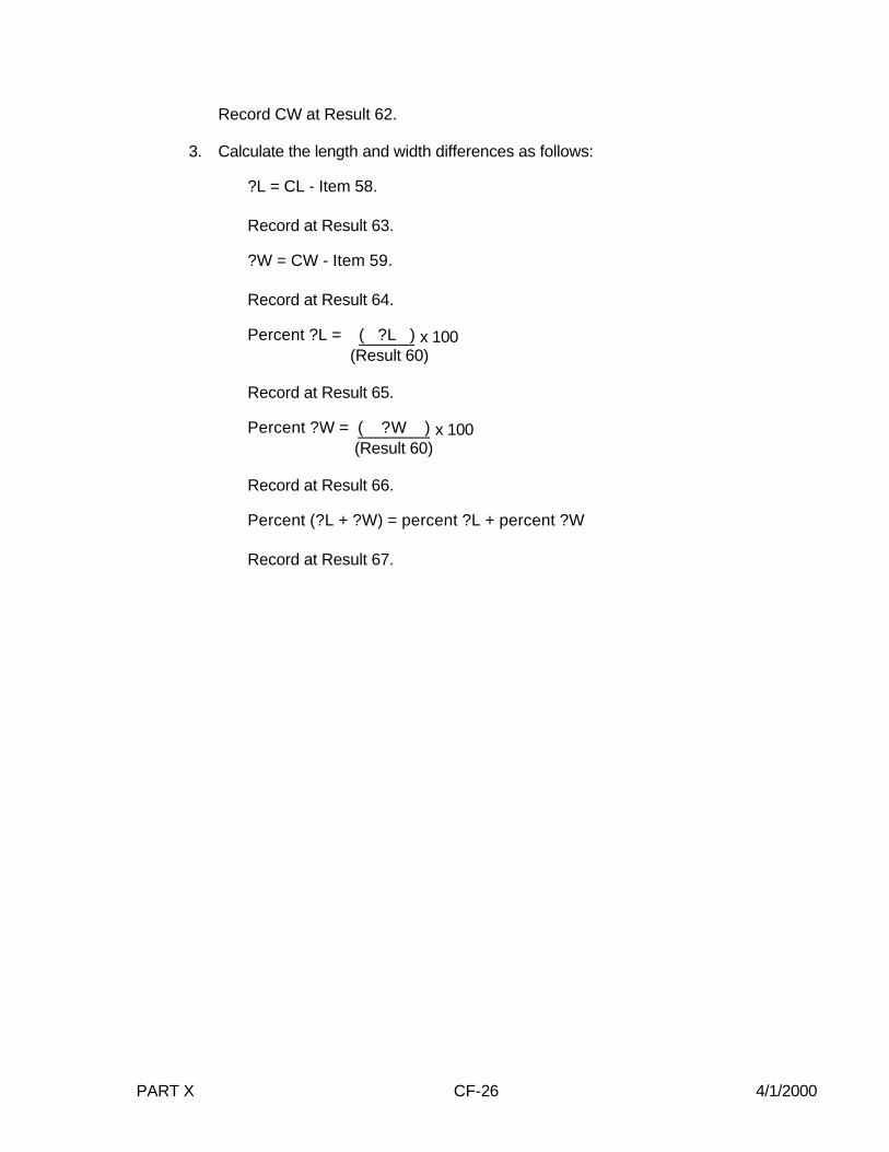
2. Calculate the length and width in the place of the image receptor, CL and CW,as follows:
CL (Calculate x-ray field length) =
CW (Calculate x-ray field width) =
Record CL at Result 61.
1X 2X
X n
= E i
n
=i∑
12
1
)1-(n
)E - X( (
E
1 = C i
n
-i
2/12
2
122
)∑
2
22 mAs
EX =
)X + X(
X - X = L
21
21
40.2) - 94 Item - 60(Result 60)(Result
x 95 Item
40.2) - 94 Item - 60(Result 60)(Result
x 96 Item
PART X CF-26 4/1/2000
Record CW at Result 62.
3. Calculate the length and width differences as follows:
?L = CL - Item 58.
Record at Result 63.
?W = CW - Item 59.
Record at Result 64.
Percent ?L = ( ?L ) x 100 (Result 60)
Record at Result 65.
Percent ?W = ( ?W ) x 100 (Result 60)
Record at Result 66.
Percent (?L + ?W) = percent ?L + percent ?W
Record at Result 67.

PART X CF-27 4/1/2000
C-arm Fluoroscopic and Spot-Film Systems
A = Distance from input phosphor of the image intensifier to the face of the image intensifier(supplied by manufacturer, if not available use 3.0 cm which is a representative value)
C = Distance from face of the image intensifier to base of the test stand.
Y = Distance from the focal spot to top of the brass strips.
Z = Distance from face of SSD spacer (or from face of BLD if spacer is not present) to top ofbrass strips.
Figure 4
S1
S6
C
A
Z
Y
BLD
/SS
DS
PA
CE
R
35.4
cm
Fluo
ro S
ID
40.2
cm
Image Intensifier

PART X CF-28 4/1/2000
Table 1. C-arm fluoroscopic and spot-film system distance from input phosphor ofI.I. to face of I.I. (A)
____________________________________________________________________________Manufacturer A
____________________________________________________________________________1. Philips BV-22 3.0 cm
2. G.E. 6" Polarix II Thompson Insert = 3.9 cmVarian Insert = 3.5 cm
3. Siemens Siremobile 4.0 cm
4. C.G.R. Optascop 8.2 cm
5. Picker Surveyor Not available
6. OEC/Varian Not available
7. Tanka MCA-30 Not available
8. Kramex STV-903 Not available____________________________________________________________________________
Image Intensifier Distance "A" in Centimeters
GE FLUORICON R L-300 VASCULAR & C-ARMS
(On digital systems remove user-insertable grid.)
12" Model 46-233653G1 HousingThomson 46-216631P1 Insert 3.3Varian 46-233654P1 Insert 1.9
9" Model 46-184080G1 HousingThomson 46-174740P1 Insert 2.3Varian 46-174055P1 Insert 1.5
GE 6"POLARIX II/II-E
Model 46-914507G1 HousingThomson 46-216076P1 Insert 3.9Varian 46-223900P1 Insert 3.5

PART X CF-29 4/1/2000
RESULTS RECORDC-ARM FLUOROSCOPIC AND SPOT-FILM SYSTEMS
(Test Procedure CFR - Form FDA 3260)
Source to Image Distance
1. Y = _______ cm.
2. Fluoroscopic SID = _______ cm.
3. Minimum SSD = _______ cm.
Fluoroscopic X-Ray Field/Image Receptor Alignment
4. Misalignment 1/4 = _______ cm.
5. Misalignment 2/1 = _______ cm.
6. Misalignment 2/3 = _______ cm.
7. Misalignment 4/3 = _______ cm.
8. SID' = _______ cm.
9. (1/4 + 3/2) misalignment = _______ cm.
10. Percent (1/4 + 3/2) misalignment = _______ cm.
11. (2/1 + 4/3) misalignment = _______ cm.
12. Percent (2/1 + 4/3) misalignment = _______ percent.
13. Total misalignment = _______ cm.
14. Percent total misalignment = _______ percent.
15. Misalignment 1/4 = _______ cm.
16. Misalignment 2/1 = _______ cm.
17. Misalignment 3/2 = _______ cm.
18. Misalignment 4/3 = _______ cm.
19. SID' = _______ cm.
20. (1/4 + 3/2) misalignment = ________ cm.
21. Percent (1/4 + 3/2) misalignment = _______ percent.
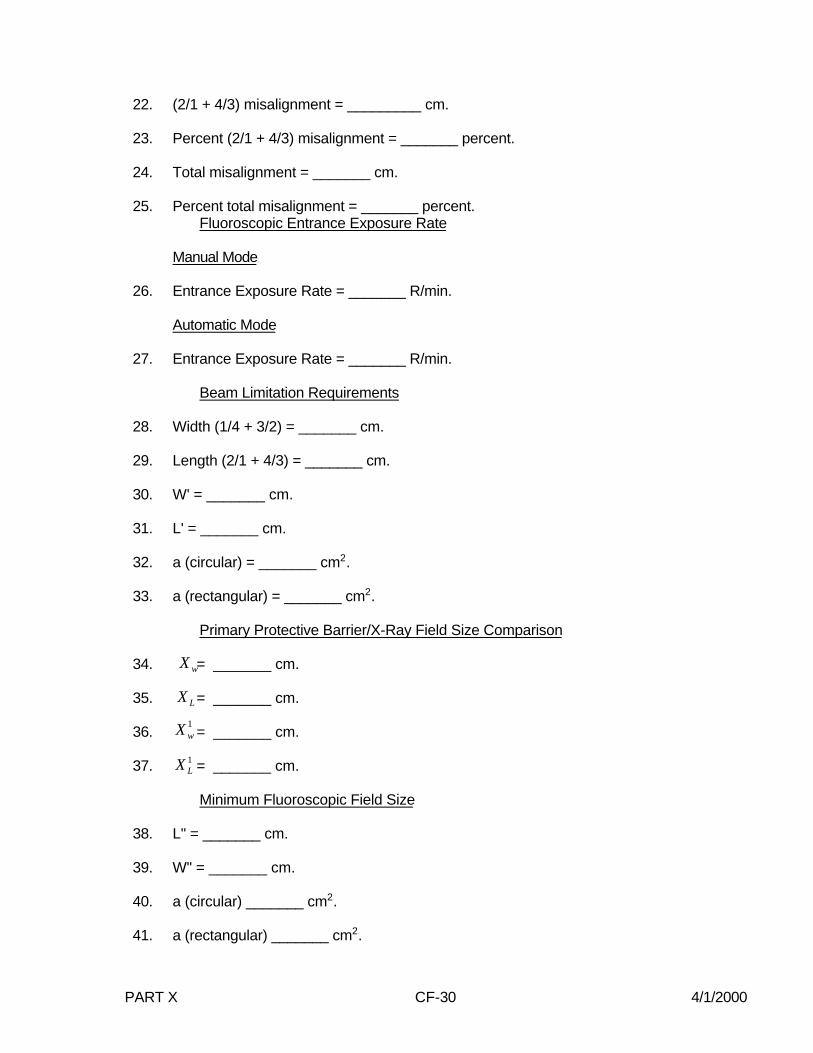
PART X CF-30 4/1/2000
22. (2/1 + 4/3) misalignment = _________ cm.
23. Percent (2/1 + 4/3) misalignment = _______ percent.
24. Total misalignment = _______ cm.
25. Percent total misalignment = _______ percent.Fluoroscopic Entrance Exposure Rate
Manual Mode
26. Entrance Exposure Rate = _______ R/min.
Automatic Mode
27. Entrance Exposure Rate = _______ R/min.
Beam Limitation Requirements
28. Width (1/4 + 3/2) = _______ cm.
29. Length (2/1 + 4/3) = _______ cm.
30. W' = _______ cm.
31. L' = _______ cm.
32. a (circular) = _______ cm2.
33. a (rectangular) = _______ cm2.
Primary Protective Barrier/X-Ray Field Size Comparison
34. = _______ cm.
35. = _______ cm.
36. = _______ cm.
37. = _______ cm.
Minimum Fluoroscopic Field Size
38. L" = _______ cm.
39. W" = _______ cm.
40. a (circular) _______ cm2.
41. a (rectangular) _______ cm2.
1wX
1LX
wX
LX

PART X CF-31 4/1/2000
Beam Quality
Exposure Rate
42. R4 = _______ mR/s at 4.5 mm Al.
43. R3 = _______ mR/s at 3.5 mm Al.
44. R2 = _______ mR/s at 2.5 mm Al.
45. R1 = _______ mR/s at 1.5 mm Al.
46. R0 = _______ mR/s at 0.0 mm Al.
Normalized Exposure Rate
47. N4 = _______ at 4.5 mm Al.
48. N3 = _______ at 3.5 mm Al.
49. N2 = _______ at 2.5 mm Al.
50. N1 = _______ at 1.5 mm Al.
N0 = 1.0 at 0.0 mm Al.
51. HVLobs = _______ mm Al at _______ kVp.
52. Actual HVL = _______ mm Al at _______ kVp.
Spot-Film Reproducibility and Linearity
53. Average exposure, , = _______ mR.
54. Coefficient of variation, C1, = _______.
5. Average exposure/mAs, = _______ mR/mAs.
56. Average exposure, , = _______ mR.
57. Coefficient of variation, C2, = _______.
58. Average exposure/mAs , = _______ mR/mAs.
59. Coefficient of linearity, L, = _______.
X-Ray Field/Spot-Film Size Comparison
60. Spot-Film SID _______ cm.
1E
1X
2E
2X
PART X CF-32 4/1/2000
61. CL = _______ cm.
62. CW = _______ cm.
63. ?L = _______ cm.
64. ?W = _______ cm.
65. Percent ?L = _______ percent.
66. Percent ?W = _______ percent.
67. Percent ?L + Percent ?W = _______ percent.

PART X CF-33 4/1/2000

PART X CF-34 4/1/2000
PART X CF-35 4/1/2000

PART X CF-36 4/1/2000

PART X CF-37 4/1/2000
SUPPLEMENTARY 1: VARIABLE C-ARM FLUOROSCOPIC SYSTEMS
C-ARM FLUOROSCOPIC AND SPOT-FILM SYSTEMS
(Test Procedure CFB - Use Form FDA 3260)
This supplementary procedure is used for testing mobile or stationary C-arm fluoroscopesthat have a variable SID. The SID may be changed by moving the position of the imagingassembly (image intensifier and spot-film device or film changer) or the diagnostic-sourceassembly or both. The same field test record, FDA 3260, is used for recording the data.
1.0 GENERAL GUIDANCE
1.1 When a step or entire section of the procedure does not apply to the system beingtested, simply pass over that step or section and continue. If passing over a step orsection means that some portion of the Field Test Record will not be completed,enter an "*" in the first column of each inapplicable item in that portion of the Record.
NOTE: If multiple indicators are provided for a single parameter(e.g., kVp, etc.) but the indicators do not agree with one another,choose the indicator (1) associated with a certified component and(2) most commonly used. Note in the REMARKS that theseindicators do not agree, and estimate the amount of discrepancy.
2.0 PRETEST CHECKLIST
2.1 Turn on the main power to the x-ray system.
2.2 If not already completed, complete the General Information Field Test Record. Enterthe field test serial number which appears preprinted on the General InformationField Test Record in the appropriate block on each page of the C-Arm Fluoroscopicand Spot-Film System Field Test Record.
2.3 Verify that the assemblers' reports, FD 2579s', are correctly prepared. If they arenot, write in the correct information above the incorrect information.
2.4 Enter the letter "B" in data item 1.
2.5 Record the system type (mobile or stationary) in item 2.
2.6 Determine from the ID label or from the installation date whether the BLD wasmanufactured after 5/22/79. Record at item 3.
2.7 Examine the control panel and the BLD to determine if collimator shutter controls areprovided. If shutter blades can be continuously varied from the maximum to theminimum field size record a "2" at item 4. If, however, beam limitation is achieved byuse of fixed apertures or cones, record a "1" at item 4.
2.8 Indicated the certification status of each component making up the system at item 5.
PART X CF-38 4/1/2000
2.9 Set up the system for fluoroscopic operation if not already done (i.e. rotate theradiographic image assembly out of the beam axis and position the fluoroscopicimage intensifier into place). If present, remove the clip-on cassette holder from theimage intensifier.
2.10 Turn on the television monitor and allow time for stabilization.
2.11 Connect the 6-cm ionization chamber to the electrometer of the model 1015F x-raymonitor. Set the x-ray monitor function selector to HOLD and the mode selector toEXPOSURE.
IMPORTANT!
Position the exposure footswitch as far as possible from the C-armor behind a protective shield. Also, always be conscious of thepresence and direction of the x-ray beam. Try to orient yourself sothat the x-ray beam is pointing away from the body.
3.0 INITIAL SETUP (FLUOROSCOPIC MODE) AND SURVEYOR PROTECTION TEST
Test Setup (See figure on test record)
(a) Tilt or rotate the C-arm into the horizontal plane (or as close to it as possible) sothat a line from the focal spot to the center of the image intensifier (II) face wouldbe parallel to the floor.
(b) Adjust the image intensifier and diagnostic source to the maximum SID that thesystem will allow. On some systems, the SID can be changed by varying witherthe position of the image intensifier or the diagnostic source assembly or both. Ifthe test is conducted on a system equipped with an x-ray table, the table mightbe used instead of the tripod as a support for the test stand. On somestationary systems, it will not be possible to rotate the C-arm into the horizontalplane. If this is the case, use the following steps:
(1) The test stand will need to be attached to the tripod on a vertical orientation(see Figure 4).
(2) On many of these systems, the x-ray beam can only be aimed at the ceilinginstead of the floor. The top of the test stand, these cases, should betowards the BLD (the test stand will be upside down).
(3) Check the orientation of the test stand with the bubble level in the test kit tomake sure it is level. A certain amount of adjustment may be necessary tomake sure that the test stand does not sag.
(c) Mount the right side of the test stand onto the tripod so that the MDH holes areon top (see Figure 1). Follow the tripod setup procedure in Appendix B of thetest procedures manual. Make sure the test stand is level by using the bubblelevel.

PART X CF-39 4/1/2000
(d) Measure the diameter of the image intensifier housing before positioning the teststand against the image intensifier. The size of the housing should besomewhat larger than the size of the input phosphor of the image intensifier. Record at item 27.
NOTE: For image intensifiers that are between 6" (15.24cm) and 9" (22.86 cm), the choice of test geometry (either6" or 9" and larger) depends on which works best for the testprocedure. If one test geometry does not work well, theother geometry might work better.
(e) Enter "006" at data item 87 if the 6" (15.24 cm) geometry is used and "009" atitem 87 if the 9" (22.86 cm) geometry is used.
NOTE: In this supplement, data items 86 and 87 will not beused for reproducibility values. Only a maximum of ninemeasurements will be used during this procedure forreproducibility.
(f) 9" (22.86 cm) or Larger Image Intensifier: Move the tripod toward the BLD untilthe test stand top is approximately centered on and about 3 cm from the face ofthe BLD or SSD spacer. The bottom opening in the test stand should becentered over the image intensifier face. Insert the slide assembly, grid sidetoward the BLD, into slot 4 of the test stand.
6" (15.24 cm) Image Intensifier: Move the tripod so that the test stand bottom isagainst the face of the II. Adjust the tripod height and tilt until the bottom openingin the test stand is flush against and centered on the face of the imageintensifier. Insert the slide assembly, grid side toward the BLD, into slot 6 of thetest stand.
(g) Center (and tape) 0.1 inch (2.54 mm) of copper on slot 7 of the test stand. (SeeFigure 2, modification of the test stand.)
(h) Insert the 6 cm3 ionization chamber through the upper mounting hole (C) of thetest stand.
TEST PROCEDURE
3.1 Select the largest cone aperture that will still permit fluoroscopy, or if a stepless BLDis provided, fully open the shutters.
3.2 Select fluoroscopic technique factors of approximately 90 kVp and 2 mA, and set thecumulative fluoro timer to its maximum setting.
3.3 Using the GM survey meter, make several short exposures and scan the work area. Not the greatest GM meter deflection. Refer to page GM-1 for instructions on theproper use of the GM meter.

PART X CF-40 4/1/2000
Figure 1

PART X CF-41 4/1/2000
Figure 2
PART X CF-42 4/1/2000
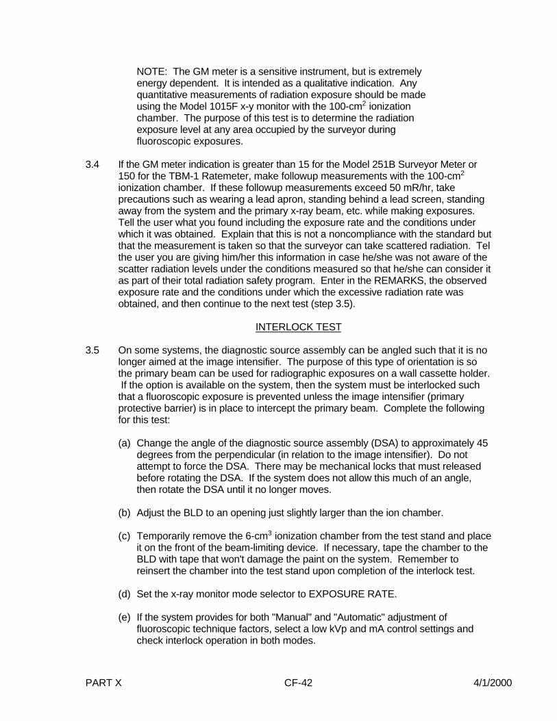
NOTE: The GM meter is a sensitive instrument, but is extremelyenergy dependent. It is intended as a qualitative indication. Anyquantitative measurements of radiation exposure should be madeusing the Model 1015F x-y monitor with the 100-cm2 ionizationchamber. The purpose of this test is to determine the radiationexposure level at any area occupied by the surveyor duringfluoroscopic exposures.
3.4 If the GM meter indication is greater than 15 for the Model 251B Surveyor Meter or150 for the TBM-1 Ratemeter, make followup measurements with the 100-cm2
ionization chamber. If these followup measurements exceed 50 mR/hr, takeprecautions such as wearing a lead apron, standing behind a lead screen, standingaway from the system and the primary x-ray beam, etc. while making exposures. Tell the user what you found including the exposure rate and the conditions underwhich it was obtained. Explain that this is not a noncompliance with the standard butthat the measurement is taken so that the surveyor can take scattered radiation. Telthe user you are giving him/her this information in case he/she was not aware of thescatter radiation levels under the conditions measured so that he/she can consider itas part of their total radiation safety program. Enter in the REMARKS, the observedexposure rate and the conditions under which the excessive radiation rate wasobtained, and then continue to the next test (step 3.5).
INTERLOCK TEST
3.5 On some systems, the diagnostic source assembly can be angled such that it is nolonger aimed at the image intensifier. The purpose of this type of orientation is sothe primary beam can be used for radiographic exposures on a wall cassette holder. If the option is available on the system, then the system must be interlocked suchthat a fluoroscopic exposure is prevented unless the image intensifier (primaryprotective barrier) is in place to intercept the primary beam. Complete the followingfor this test:
(a) Change the angle of the diagnostic source assembly (DSA) to approximately 45degrees from the perpendicular (in relation to the image intensifier). Do notattempt to force the DSA. There may be mechanical locks that must releasedbefore rotating the DSA. If the system does not allow this much of an angle,then rotate the DSA until it no longer moves.
(b) Adjust the BLD to an opening just slightly larger than the ion chamber.
(c) Temporarily remove the 6-cm3 ionization chamber from the test stand and placeit on the front of the beam-limiting device. If necessary, tape the chamber to theBLD with tape that won't damage the paint on the system. Remember toreinsert the chamber into the test stand upon completion of the interlock test.
(d) Set the x-ray monitor mode selector to EXPOSURE RATE.
(e) If the system provides for both "Manual" and "Automatic" adjustment offluoroscopic technique factors, select a low kVp and mA control settings andcheck interlock operation in both modes.

PART X CF-43 4/1/2000
(f) Before making an exposure, position the exposure foot-switch as far from thesystem as possible. Be sure to stand as far away from the primary beam aspossible.
(g) Momentarily depress the exposure foot-switch. Observe the x-ray monitor andx-ray control for any indication of x-ray exposure.
(h) If the system allows an exposure without the image intensifier (primaryprotective barrier) in place to intercept the primary beam, then enter "Y" in item6. Otherwise, enter "N".
It is not necessary at this point to discontinue all further testing. However, cautionmust be used so that accidental depression of the foot switch does not occur if thediagnostic source assembly is no longer aimed at the image intensifier.
3.6 Is there a warning label present on the control panel containing the main powerswitch as prescribed in 21 CFR 1020.30(j)? Record at item 7.
4.0 FLUOROSCOPIC X-RAY FIELD/IMAGE RECEPTOR ALIGNMENT
Test Setup
Same as initial setup.
Test Procedure
4.1 Either the MANUAL or AUTO brightness control modes may be used. Make anexposure and observe the slide assembly grid image on the TV monitor. Adjust thebrightness control or the technique factors until a good quality image of the grid isobtained.
4.2 Verify that the grid is approximately centered on the TV monitor. If it is not, slightlymove the tripod with the x-ray beam off until approximate centering is obtained.
4.3 Set the x-ray monitor mode selector to EXPOSURE and the function selector toMEASURE. Leakage on the instrument should not exceed 4 mR in one minute. If itdoes, the instrument may be defective and you should contact CDRH for guidance.
4.4 Verify that the BLD is still fully open.
4.5 Insert a plastic cassette containing a sheet of direct-print paper into the slideassembly at slot 6 (slot 4 for 9" (22.86 cm) of larger image intensifier).
4.6 Insert the focal-spot into slot 1 of the test stand with the brass strips toward thebeam-limiting device. Measure to the nearest millimeter the distance from the faceof the source-skin distance (SSD) spacer (or the face of the BLD if a spacer is notpresent) to the top of the brass strips of the focal-spot assembly. Record at item 43.
PART X CF-44 4/1/2000
NOTE: If the system is not equipped with a radiographic mode thatwill be tested in section 13.0, it will be necessary to make an imageof the brass strips of the focal-spot assembly during this section ofthe procedure. If this is necessary, make sure that the image benecessary to move the test stand away from the BLD to see bothbrass strips on the TV monitor. Be sure, however, that the x-ray fieldat the slide assembly is not now so large that it extends beyond theedge of the direct-print paper. If you expose a sheet of direct-printpaper, but do not get both the image of the brass strips and all edgesof the x-ray field on the paper, adjust the position of the test standand conduct this test a second time with the test sand in thisreadjust position. Make sure that the test data recorded on the fieldtest record reflects the final position of the test stand and geometryused.
4.7 Some variable C-arm systems are equipped with three-field image intensifiers. Ifthis is the case, start the test in the nonmagification mode and record the data atitems 8-15. If there is no magnification mode leave items 16-23 blank.
4.8 Measure to the nearest millimeter the distance from the face of the image intensifierto the SSD spacer (or face of the BLD if spacer is not present). Record at item 93.
4.9 Make an exposure and read the dimensions of the grid that are visible at each edge.
NOTE: See lines 1/4, 2/1, 3/2 and 4/3 of figure 3. For futurereference, observe that 1/4 passes between the slide assemblyquadrant numbers 1 and 4, etc., and each small division of the gridrepresents 0.1 inch (2.54 mm). If the focal-spot strip image ispresent on the television monitor, make sure that the griddimensions can be read. If they cannot be read, it may benecessary to remove the focal-spot assembly temporarily beforereturning it to the test stand.
4.10 Record the values in order from 1/4 to 4/3 at items 8 through 11.
4.11 If the accumulated exposure is 4 R or greater, the direct-print paper should provide asatisfactory image. Make any additional exposure required to obtain a total of 4 R.
4.12 Remove the cassette from the slide assembly and develop the direct-print paper byexposure to fluorescent light. (Refer to page LINA-1 for proper developmenttechnique). If a satisfactory image of the focal-spot strips is visible on the paper,then the focal-spot assembly may be removed form the test stand.
NOTE: If the system does not hove a radiographic mode, then thissheet of direct-print paper for the FLUOROSCOPIC X-RAYFIELD/IMAGE RECEPTOR ALIGNMENT test must be retained andused for later calculation of source-to-skin distance.
4.13 Measure to the nearest millimeter the distance from the center of the grid to the
PART X CF-45 4/1/2000
12
3 4
Figure 3
Along Table Direction
Acr
oss
Tab
le D
irec
tion

PART X CF-46 4/1/2000
image along each of the four lines 1/4 through 4/3.
NOTE: Again observe that 1/4 passes between the slide assemblyquadrant numbers 1 and 4, etc.
4.14 Record the vales in order from 1/4 to 4/3 at items 12 through 15.
4.15 Insert a plastic cassette containing a sheet of direct-print paper into the slideassembly.
4.16 If the mode of greatest magnification on a three-field image intensifier allows you toread the dimensions of the grid image, then perform this test in this mode. There isno need to test the mode of lesser magnification (e.g. middle mode) unless the griddimensions cannot be read in the mode of greatest magnification. Repeat steps 4.9through 4.13 for the magnification mode and record the data at items 16 through 23.
4.17 Record the shape of the visible area at 24.
4.18 Tube potential and current must be continuously indicated during exposure, but notnecessarily at the operator's position. Record at item 25.
4.19 Verify that the maximum setting for the fluoro timer is five minutes or less. Record atitem 26.
5.0 PRIMARY PROTECTIVE BARRIER/X-RAY FIELD SIZE COMPARISON
5.1 Measure to the nearest millimeter the distance from the face of the image intensifierto the base of the test stand. Record at item 28. When the bottom of test stand isflush against the image intensifier (setup for 6" (15.24 cm) image intensifier), leaveitem 28 blank for later use.
6.0 MINIMUM FLUORO X-RAY FIELD SIZE
Test Setup
Same as initial setup.
Test Procedure
6.1 Select the smallest BLD aperture or cone. If a stepless collimator is provided, closethe collimator completely and make a short exposure to see if any visible area canbe observed. If none is observed skin the rest of this procedure and record "00.0" atitems 29 and 30 and an asterisk at item 31. If a visible area is observed, proceedwith step 6.2.
6.2 Insert a plastic cassette containing a sheet of direct-print paper into the slideassembly.
6.3 Make an exposure to obtain at least 1.5 R to the ionization chamber.
PART X CF-47 4/1/2000
6.4 Remove the cassette from the slide assembly and develop the direct-print paper byexposure to fluorescent light. (Refer to page LINA-1 for Proper developmenttechnique.)
6.5 Measure to the nearest millimeter the length and width of the x-ray field image. Record at items 29 and 30. If the field image is circular, record the diameter twice atitems 29 and 30.
6.6 Record the x-ray field image shape at item 31.
Fluoroscopic Technique Factor Control Type
Are the fluoroscopic technique factors manually controlled,automatically controlled, or are both manual automatic fluoroscopictechnique factor controls provided? Record at item 32. It may benecessary to refer to the Users Manual for an exact answer to thisquestion.
7.0 ENTRANCE EXPOSURE RATE - MANUAL MODE
Test Setup (See figure on test record.)
(a) Adjust the image intensifier and diagnostic source assembly to the minimum SIDthat the system will allow. On some systems, the SID can be changed by varyingeither the position of the image intensifier or the diagnostic source assembly or both. If the minimum SID does not provide enough space between the image intensifierand the BLD for the test stand, skip to step (f).
(b) Move the test stand until the base of the test stand is against the image intensifier.
(c) If the collimator is equipped with a light localizer, turn it on and adjust the size of thelight field at the top of the test stand, such that the light field passes through theopening at the top of the test stand.
(d) Insert the beam-defining assembly into slot 1. If the system is not equipped with alight localizer, but has a variable-aperture collimator, make an exposure. Reduce thesize of the x-ray field so that it is just large enough to image the aperture of thebeam-defining assembly on the television monitor (this information also applies tothe automatic mode).
(e) Measure to the nearest millimeter the distance from the face of the source-skindistance (SSD) spacer (or the face of the BLD if a spacer is not present) to thecenter of the ion chamber. Record at item 86 (10th data item box for reproducibilityin the main procedure is used to record this distance when using this supplement).
(f) Short Minimum SID - Some systems have a minimum SID which allows less than40 cm. of space between the face of the source-skin distance (SSD) spacer (or theface of the BLD if a spacer is not present) and the face of the image intensifier. Since this is the height of the test stand, it cannot be placed in the x-ray beam forEER measurements. Proceed with steps (1) through (6).

PART X CF-48 4/1/2000
(1) Remove the test stand from the space between the BLD and the imageintensifier.
(2) Reverse the 6-cm3 ion chamber at the top mounting hole of the test stand suchthat the ion chamber is sticking out of the side of the test stand. Center the ionchamber beneath the source assembly. The bottom of the test stand must beeven with the face of the image intensifier.
(3) Lower the source assembly such that the end of the face of the source-skindistance (SSD) spacer (or the face of the BLD if a spacer is not present) is asclose as possible to the ion chamber.
(4) Center 0.1 inch (2.54 mm) of copper on the center of the image intensifier. Becareful to cover the face of the image intensifier with paper or cloth to preventscratches to the face of the image intensifier.
(5) Make an exposure and observe the image of the ion chamber on the TV monitor. Make sure the aperture of the BLD is opened sufficiently to cover the entire ionchamber.
(6) Measure to the neatest millimeter the distance from the face of the source-skindistance (SSD) spacer (or the face of the BLD if a spacer is not present) to thecenter of the ion chamber. Record at item 86 (10th data item box forreproducibility in the main procedure is used to record this distance when usingthis supplement). If the ion chamber is touching the face of the source-skindistance (SSD) spacer (or the face of the BLD if a spacer is not present), thenenter 000.0 at item 86.
Test Procedure
7.1 Remove the slide assembly from the test stand, if present.
7.2 Set the fluoroscopic technique factor control mode to "Manual." The "Manual" modemay be checked by inserting additional copper in the beam. Observe the exposurerate with and without the additional copper. If the system is in "Manual" mode,exposure rates in each case should be about the same. Remove any additionalcopper after this check.
7.3 Some systems do not yield their maximum entrance exposure rate at maximumtube potential or tube current; therefore, check the exposure rate at various kVp andmA settings to establish worst-case technique factors. Set the x-ray monitor modeselector to EXPOSURE RATE. While making an exposure, vary the kVp and mAsettings to maximize the electrometer reading. Record the worst-case kVp and mAat items 33 and 34, respectively. Record the maximum exposure rate at item 35.
NOTE: Since the MDH 1015F provides an indication of the averageexposure rate every 1.2 seconds, the kVp and mA settings must bevaried slowly to maximize the electrometer reading.

PART X CF-49 4/1/2000
7.4 If means to activate a high-level control are provided, make an exposure. Note theexposure rate. While making the exposure, activate the high-level control. Vary thekVp and mA settings to maximize the exposure rate. Record the high-level exposurerate in the Remarks. Use the following format:
7.4 HLC MODE: _______ kVp ______ mA _________ R/min
NOTE: Since on some systems the hookup of a high-level control isa user option, means to activate a high-level control (e.g., button ordouble detent foot switch) may be present but not hooked up. Therefore, to determine the presence or absence of such a control,a radiation exposure rate check must be made.
Special means of activation are required for high-level controls, otherthan that required to activate normal fluoroscopy. Also, continuousmanual pressure must be applied for the operation of the high-levelcontrol. This means that fluoroscopic operation cannot be "locked"in the high-level control mode. For controls manufactured after May19, 1995, the HLC mode is limited to 20 R/min. Be aware of heatloading conditions and only run long enough to obtain adequate data.
7.5 If the high-level exceeds the low-levels rate, record “y” in item 36. Otherwise, record“n” in item 36.
7.6 Is there a continuous audible signal provided upon activation of the high-levelcontrol? Record at item 37. If a high-level control is not present, record "X" at item37. If special means of activation or continuous manual pressure are not providedfor the high-level control, explain the operation of the high-level control in theREMARKS section.
NOTE: For x-ray controls manufactured after May19, 1995,the EER requirements donot apply to the recording of fluoroscopic images when operating in a pulsed mode. In addition, the recording mode is not considered high-level control and therefore, noaudible signal is required. The Center is looking into the record mode uses andwould need manufacturer justification for any unit that could operate only in a recordmode.
8.0 ENTRANCE EXPOSURE RATE - AUTOMATIC MODE
Test Setup
Same as manual mode except: Center a 1/8 inch (3.18 mm) thick lead sheet over the 0.1inch (2.54 mm) of copper and tape into place. Remove the slide assembly from the teststand, if present.
Do not change the SID from the EER test that was conducted in the manual mode. Whentesting large image intensifiers, the beam may extend around the lead sheet present in slot7. If this happens, the edge of the image intensifier becomes illuminated and the EER drops

PART X CF-50 4/1/2000
accordingly. Place the beam-defining assembly in slot 1 to determine if the EER changes. If this makes a difference, conduct the test with the beam-limiting assembly in place. If thefocal-spot assembly is still in the test stand from section 4.0 then remove it.
Short Minimum SID - Some systems have a minimum SID which allows less than 40 cm. ofspace between the face of the source-skin distance (SSD) spacer (or the face of the BLD ifa spacer is not present) and the face of the image intensifier. Since this is the height of thetest stand, it cannot be placed in the x-ray beam for EER measurements. The setup will beessentially the same as in the manual mode (step f). Be careful to cover the face of theimage intensifier with paper or cloth to prevent scratches to the face of the image intensifier. If the beam extends around the lead sheet, reduce the size of the x-ray field with the BLDshutters to see if the EER changes. If this makes a difference, conduct the test with theshutters in this position, but open enough not to shield the ion chamber. This may bechecked by observing the image of the ion chamber on the TV monitor when the lead is notin the beam.
Measure to the nearest millimeter the distance from the face of the source-skin distance(SSD) spacer (or the face of the BLD if a spacer is not present) to the center of the ionchamber. Record at item 86 if not already recorded in section 7.0 (10th data item box forreproducibility in the main procedure; used to record this distance when using thissupplement). If the ion chamber is touching the face of the source-skin distance (SSD)spacer (or the face of the BLD if a spacer is not present), then enter 0000.0 at item 86.
Test Procedure
8.1 Set the fluoroscopic technique factor control to "Automatic" mode and any"Automatic Brightness Control" for maximize brightness. The "Automatic" modemay be checked by observing the exposure rate with and without the 1/8 inch (3.18mm) lead sheet in the beam. If the system is in "Automatic" and the kVp and mA arenot at their maximum values, the exposure rate should be higher with the lead in thebeam.
8.2 Set the x-ray monitor mode selector to EXPOSURE RATE. While making anexposure, vary the kVp and/or mA settings to obtain the maxim electrometer reading. Record the indicated tube potential and tube current at items 38 and 39,respectively, and the exposure rate at item 40.
8.3 If means to activate a high-level control are provided, make an exposure. Note theexposure rate. While making an exposure activate the high-level control. Vary thekVp and mA setting to maximize the electrometer reading. Record the high-levelexposure rate in the Remarks section using the following format
8.3 HLC MODE: _______ kVp ______ mA _________ R/min
NOTE: Since on some systems the hookup of a high-level control isa user option, means to activate a high-level control (e.g., button ordouble detent foot switch) may be present but not hooked up. Therefore, to determine the presence or absence of such a control,a radiation exposure rate check must be made.

PART X CF-51 4/1/2000
Special means of activation are required for high-level controls, otherthan that required to activate normal fluoroscopy. Also, continuousmanual pressure must be applied for the operation of the high-levelcontrol. This means that fluoroscopic operation cannot be "locked"in the high-level control mode.
8.4 If the high-level exceeds the low-level rate, record "Y" in item 35. Otherwise, record"N" in item 35.
8.5 Is there a continuous audible signal provided upon activation of the high-levelcontrol? Record at item 42. If a high-level control is not present, record "X" at item42. If special means of activation or continuous manual pressure are not providedfor the high-level control, explain the operation of the high-level control in theREMARKS section.
NOTE: For x-ray controls manufactured after May19, 1995,the EER requirements donot apply to the recording of fluoroscopic images when operating in a pulsed mode. In addition, the recording mode is not considered high-level control and therefore, noaudible signal is required. The Center is looking into the record mode uses andwould need manufacturer justification for any unit that could operate only in a recordmode.
9.0 SID AND MINIMUM SSD
(This section is moved to follow section 12.0 in order to facilitate proper datacollection sequence.)
10.0 BEAM QUALITY
Test Setup (See figure on test record)
(a) Remove the lead from slot 7 (if present from section 8.0).
(b) Move the 6 cm3 ionization chamber to the lower mounting hole (D) of the teststand.
(c) Place 4.5 mm aluminum of the beam defining assembly in slot 1.
Test Procedure
10.1 (a) If the system has only an automatic mode of operation, go directly to step 10.5.
(b) If the system has a manual fluoroscopic technique factor control mode, selectthis manual mode.

PART X CF-52 4/1/2000
MANUAL MODE
10.2 Set the tube potential to a commonly used value above 70 kVp and the tube currentto at least 2.0 mA. Record the kVp at item 45.
10.3 Five exposures are required for the beam quality determination. With the x-raymonitor selector in PULSE EXPOSURE, reset the x-ray monitor by switching thefunction selector to HOLD and back to MEASURE. The display should indicate -0.00. Make an exposure of at least 10 seconds at the selected kVp. Record theexposure reading in item 46. Switch the function selector to pulse duration andrecord the time reading at item 47. Reset the x-ray monitor after the exposure byswitching the function selector to HOLD and then back to MEASURE.
NOTE: If a time measurement has not been obtained or appearserroneous, the exposure rate may be too low to trigger the MDHinstrument. For this situation, the mA and/or kVp must be increased. If kVp is changed, the kVp recorded at item 45 must also bechanged.
10.4 Remove aluminum to obtain totals of 3.5, 2.5, 1.5, 0.0 millimeters on top of the beamdefining assembly. For each total, make an exposure as described in step 10.3. Record the exposure and time at items 48 through 55. Remember to reset the x-raymonitor between each exposure. Skip to 10.7.
AUTOMATIC MODE ONLY
10.5 Set the tube potential to a commonly used value above 70 kVp and the tube currentto at least 2.0 mA. Record the kVp at item 45. Five exposures are required for thebeam quality determination. With the x-ray monitor mode selector in PULSEEXPOSURE, reset the x-ray monitor by switching the function selector to HOLD andback to MEASURE. The display should indicate -0.00. Make an exposure of at least10 seconds at the selected kVp. Record the exposure reading at item 46. Switchthe function selector to PULSE DURATION and record the time reading at item 47.
NOTE: If a time measurement has not been obtained or appearserroneous, the exposure rate may be too low to trigger the MDHinstrument. For the situation, the mA and/or must be increased. IfkVp is changed, the kVp recorded at item 45 must also be changed.
10.6 Move aluminum from slot 1 of the test stand (toward the BLD) to slot 7 (toward the II)so that the totals of 3.5, 2.5, 1.5, and 0.0 millimeters are left on the top of beamdefining assembly. For each total of aluminum, make an exposure as described in10.4 while RESETTING THE X-RAY MONITOR EACH TIME. Record the exposureand time at items 48 through 55, respectively.
10.7 Set the cumulative fluoro timer to a very short time interval, only a few seconds ifpossible, and make an exposure of duration greater than the preset time interval. Atthe end of the preset interval, does either a continuous audible signal indicate theend of the interval and/or is x-ray production terminated? Record at item 56.

PART X CF-53 4/1/2000
11.0 RADIOGRAPHIC MODE
11.1 A radiographic mode is normally available on C-arm fluoroscopes. Usually, but notalways the radiographic images are recorded on a spot-film device (a clip-oncassette holder or a cut-film changer). Occasionally, a fluorographic camera isprovided (e.g. a 105 mm camera) for recording images off the output phosphor ofthe image intensifier. Such a camera is not a spot-film device. Indicate at item 57the type of spot-film device provided. If only a fluorographic camera is provided,continuation of the test procedure is not appropriate. Skip sections 11, 12, and 13and enter and "*" at data item 57.
NOTE: Determination from the user if the system allowsradiographic exposure if no present in the film changer. If film isrequired, then make sure the user does not object to the film usageduring the radiographic portions of the procedure. As an alternativeto making exposure on unexposed film, the film changer magazinecan be filled with exposed film.
11.2 Record the dimensions of the spot-film image receptor or the cut-film nominal sizeat items 58 and 59.
11.3 If both Manual and Automatic (phototimed) exposure modes are provided, select themost commonly used mode of operation.
11.4 Set the tube potential to a value commonly used. Record at item 67.
11.5 Automatic:
(a) If testing in the phototimed mode, record an "*" in the first column of any of item67 which is not preindicated.
11.6 Manual:
(a) If independently selected, choose values of tube current and exposure time, andrecord at item 67.
(b) If only the mAs is selectable, choose a value commonly used and record at item67.
11.7 Is the system single-phase or three-phase? Record at item 66.
NOTE: Using one or more of the following methods, determinewhether the system is single-phase or three-phase:
(1) Consult the user or the information provided to him by the high voltage generatormanufacturer.
(2) Check the identification plate to see if the manufacturer has listed he phase ofthe system along with other electrical characteristics.

PART X CF-54 4/1/2000
(3) Observe the time setting on the control panel. Single-phase timer setting areusually expressed as common fraction multiples of 1/120 second, while three-phase systems usually have timer settings expressed as decimal fractions.
If the system is single-phase, set the x-ray Monitor thumbwheel switch to 0.2,and record at item 65.
If the system is three-phase, set the x-ray Monitor thumbwheel switch to 0.5 andrecord at item 65.
11.8 Set the system to the maximum SID. This should be the worst-case condition forthe size comparison test. If a variable-aperture collimator is present, adjust it to thelargest possible x-ray field size.
11.9 For systems equipped with 9" (22.86 cm) or larger image intensifiers, move the teststand to the exact position that it was located at in section 4.6. The distance fromthe SSD spacer or BLD to the focal-spot assembly should have been recorded atitem 43.
For systems equipped with a 6" (15.24 cm) image intensifier, position the test standsuch that the top of the test stand is approximately 3 cm from the SSD spacer (orthe face of the BLD if a spacer is not present).
11.10 Set the x-ray monitor mode selector switch to PULSE EXPOSURE.
11.11 If a clip-on cassette holder is provided, mount it over the face of the image intensifier. Insert an empty cassette into the cassette holder.
11.12 If the system is equipped with a permanently-mounted film changer, rotate or move itinto the beam.
11.13 On some systems, a rad-fluoro mode selector switch is provided on the controlpanel. If this is the case, switch to the radiographic mode.
NOTE: It must be possible to maintain the fluoro field size duringspot-filming. The user, at his option, may select automatic fullcoverage of the spot-film, but there must be an option on the controlpanel. A system design that always provides for automatic fullcoverage of the spot-film is noncompliance. Record at item 64.
12.0 REPRODUCIBILITY AND LINEARITY
Test Setup (See figure on test record)
(a) Remove the beam defining assembly from slot 1 and replace it with the focal-spot assembly with the brass strips toward the BLD. Tape down the focal-spotassembly.

PART X CF-55 4/1/2000
(b) Move the 6 cm3 ionization chamber to the upper mounting hole (C) of the teststand.
(c) If the test stand top has the optional Plexiglas railings attached, remove theserailings by loosening the retaining screws. Center a plastic cassette containinga sheet of direct-print paper on top of the test stand and tape in place.
(d) Insert the slide assembly, grid side up, into slot 6 of the test stand. Insert aplastic cassette containing direct-print paper into the slide assembly.
Test Procedure
12.1 Adjust the BLD so that it is fully open.
12.2 (a) If both "manual" and "automatic" controls are provided for exposure termination,select the mode of operation most commonly used. If the "manual" mode ofoperation is chosen, complete steps 12.3 through 12.11 and skip steps 12.12through 12.16.
(b) If the "automatic" technique factor control mode is selected, go directly to 12.12.
MANUAL MODE
12.3 Set the x-ray monitor mode selector to PULSE EXPOSURE. Reset the x-raymonitor so that the display reads -0.00. Without changing the technique factors,make an exposure. Do not record the resultant reading.
12.4 Without changing technique factors or the x-ray monitor settings, make andadditional exposure. The reading will now have no minus sign present. Record thisreading of pulse exposure at item 68. Switch the mode selector to PULSEDURATION and record this reading at item 69. Switch the mode selector back toPULSE EXPOSURE.
12.5 Make three additional exposures, with the exposure readings being recorded at items70, 72, and 74, and the corresponding time readings at 71, 73, and 75. Do not resetthe x-ray monitor between exposures. If any two readings differ by more than 10percent of the largest value, make five additional exposures. Record the additionalexposures and corresponding time readings at items 76 through 85 for a total of ninedata points (items 86 and 87 have already been used). All variable controls fortechnique factors shall be adjusted to alternate settings and reset to the test settingafter each measurement.
12.6 If the x-ray control is manufactured before May 1994, follow the guidance ofparagraph a. under each step for this test section, otherwise use paragraph b.
a. If the unit under test either does not allow specific selection of tube current, or, ifonly mAs is selectable, then omit procedural steps 12.7 through 12.12, enter anasterisk in the first column of item 88 on the test record, and state in theREMARKS that the mA is fixed, or that only mAs is selectable.
PART X CF-56 4/1/2000
b. Enter a new mAs product (not to exceed twice the first mAs product) at item 88on the test record. If a new mAs product cannot be obtained, then enter anasterisk in the first column of item 88 on the test record and state in theREMARKS that the mAs product is fixed.
12.7 a. If tube current selection is in fixed steps, select an adjacent tube current stepand record the indicated value at item 88.
b. If tube current or mAs is in fixed steps, select an adjacent setting and record themAs product at item 88.
12.8 a. If tube current selection is continuous (i.e., not in discrete steps), select asecond tube current not differing from the first by more than a factor of 2, andrecord its value at item 88.
b. If the tube current or mAs is continuous (i.e. not in discrete steps), select asecond setting not differing from the first by more than a factor of 2, and recordthe mAs product at item 88.
12.9 The change in tube current may cause in tube potential. If manual compensation isavailable, readjust the tube potential to its original value, and continue with step12.11. However, if the kVp cannot be compensated back to its original setting, enteran "*" in the first column of item 89, skip procedural step 12.11, and state in theREMARKS that the kVp could not be compensated.
12.10 Make four exposures at the selected technique factors and vary the techniquefactors between each measurement as in step 12.5 and record the exposurereadings at items 89-92.
12.11 Sum the exposures entered in items 68-92. If the sum is 1.5 R or greater, the direct-print paper should provide a satisfactory image. Make additional exposures, ifrequired, to obtain at least 1.5 R to the ionization chamber. Remove the slideassembly from the test stand and proceed to step 12.17.
AUTOMATIC MODE
12.12 With the x-ray monitor mode selector at pulse exposure, reset the x-ray monitor beswitching the mode selector to HOLD and then back to MEASURE. The displayshould indicate -0.00. Make an exposure at the selected tube current. DO NOTrecord the resultant reading.
IMPORTANT!
If the exposure time recorded by the x-ray monitor is less than 100milliseconds, then reduce the tube potential or increase the copper in thebeam in slot 7 to increase the exposure time above this minimum value andrepeat the test exposure. Adjustment of the density setting for the automaticmode may increase the exposure time. Correct item 67 if necessary.
12.13 Without changing technique factors or the x-ray monitor settings, make an additional
PART X CF-57 4/1/2000
exposure. The reading will now have no minus sign present. Record the reading ofexposure at item 68. Switch the function selector to PULSE DURATION and recordthis reading at item 69. Switch the function selector back to PULSE EXPOSURE.
12.14 Make three additional exposures, with the exposure readings being recorded at items70, 72, and 74, and the corresponding time readings at 71, 73, and 75. Do not resetthe x-ray monitor between exposures. If any two readings differ by more than 10percent of the largest value, make five additional exposures. Record the additionalexposures and corresponding time readings at items 76 through 85 for a total of ninedata points (items 86 and 87 have already been used). All variable controls fortechnique factors shall be adjusted to alternate settings and reset to the test settingafter each measurement.
12.15 Sum the exposures entered in items 68-85. If the sum is 1.5 R or greater, then thedirect-print paper should provide a satisfactory image. Remove the cassette fromthe slide assembly and develop the direct-print paper by exposure to fluorescentlight. (Refer to page LINA-1 for proper development technique.)
12.16 Enter an "*" in the first column of item 88.
12.17 Are the technique factors, fixed or selectable, indicated prior to exposures? Recordat item 60, and state in the remarks whether the mA is fixed or mAs is selectable.
12.18 Was there a visible "beam-on" indication the exposure? This requirement can bemet by a meter that deflects during exposure, an indicator light that is activatedduring exposure, or some similar indication. Record at item 61.
12.19 Was there an audible indication of exposure termination? This requirement can bemet by the sound of the mechanical contractor terminating the exposure or othermechanical or electronic sound-generating devices. Record at item 62.
12.20 Did the radiographic timer terminate the exposure? Record at item 63.
9.0 SID AND MINIMUM SSD
Test Procedure
9.1 If the system has a radiographic mode, then the direct-print paper from step 12.11 orstep 12.15 will be used in step 9.3 below for calculation purposes.
9.2 If the system u not equipped with a radiographic mode, such as a film changer or aclip-on spot-film device, then refer back to the image on the direct-print paper thatwas developed in step 4.12. There should be an image of the focal-spot strips onthe direct-print paper. This paper should be used in step 9.3 below for calculationpurposes.
9.3 Measure to the nearest millimeter the minimum separation of the outside edges ofthe focal-spot strip images. Record at item 44.

PART X CF-58 4/1/2000
13.0 X-RAY FIELD/SPOT FILM SIZE COMPARISON
Test Setup
Same as Reproducibility and Linearity.
Test Procedure
13.1 Measure to the nearest millimeter the distance from the spot-film image receptor tothe bottom of the test stand. Record at item 94. On many systems, it will be difficultto obtain of the film plane inside a film changer. It may be recessed 5 cm. from thefront panel of the changer. Ask the operator or check the user's manual todetermine this location if it is not indicated on the unit.
13.2 Remove the plastic cassette from the top of the test stand and develop the direct-print paper by exposure to fluorescent light. (Refer to page LINA-1 for properdevelopment technique>)
13.3 Measure to the nearest millimeter the length and width of the x-ray field image. Record at items 95 and 96. If the field is circular, record the diameter twice at items95 and 96. For systems equipped with a 6" (15.24 cm) image intensifier, measure tothe nearest millimeter the distance from the face of the source-skin distance (SSD)spacer (or the face of the BLD if a spacer is not present) to the top of the brassstrips. Record at item 28.

PART X CF-59 4/1/2000
SUPPLEMENT 1: VARIABLE SID C-ARM FLUOROSCOPIC SYSTEMS
FIELD TEST RECORD EDIT CHECKS
Verify that:
1) Items 2, 3, and 4 have been answered.
2) Data items 12 through 15, and 20 through 23 are recorded in centimeters. Thus,these data items should be approximately 2.5 times data items 8 through 11, and 16through 19, respectively.
3.) Image dimensions (items 8 through 11) are not greater than the corresponding x-rayfield dimensions (items 12 through 15).
4) Items 24, 27, and 28 have been completed.
5) Item 27 is in the range of 10-40 cm.
6) The distance from the bottom of the test stand to the face of the image intensifier (6"geometry) or the distance from the source-skin spacer or BLD to the top of thebrass strips (9" geometry) (item 28) is less than 75 cm.
7) If data item 32 is marked M, data is present at data items 33 through 37.
8) If data item 32 is marked B, data is present at data items 33 through 42.
9) If data item 32 is marked A, data is present at data items 38 through 42.
10) Values for items 43 and 44 have been entered.
11) The distance from the source-skin spacer or BLD to the top of the brass strips (6"geometry) or the distance from the bottom of the test stand to the face of the imageintensifier (9" geometry) (item 43) is less than 75 cm.
12) Item 44 is in the range of 10-15 cm.
13) If item 57 is answered "1" or "2", then items 58 and 59 have been completed andentered in the appropriate data blocks.
14) A quick check of beam quality indicates that the appropriate amount of aluminumwas present during the test by comparing normalized exposures for each data item.
15) If only four exposures are entered for reproducibility, no two exposures differ by morethan ten percent of the highest value.
16) The distance from the source-skin spacer or BLD to the top of the brass strips (item86) is less than 75 cm.

PART X CF-60 4/1/2000
17) The identification code for the test geometry used (item 87) is either "006" or "009".
18) If a mA value is entered for linearity at item 88, then items 89 through 92 have beencompleted.
19) If item 57 is answered "1" or "2", then items 93 through 96 have been completed.
20) The distance from the bottom of the test stand to the face of the image intensifier(item 94) is less than 75 cm.
21) If the control is manufactured after May 1994, then item 88 is in units of mAs product.

PART X CF-61 4/1/2000
CALCULATION TECHNIQUE
C-ARM FLUOROSCOPIC AND SPOT-FILM SYSTEMS
SUPPLEMENTARY CALCULATIONS FOR SYSTEMS WITH VARIABLE SID
(Test Procedure CFB - Form FDA 3260)
A. Calculation of Value "Y"
1. Refer to data Item 44 of the Field Test Record.
For systems equipped with a 6" image intensifier (with or without a radiographicmode):
For systems equipped with a 9" or larger image intensifier and a radiographic (film) mode,use the above equation. For systems without a radiographic mode and a 9" or larger imageintensifier:
Record Y at Result 1.
B. Minimum Source to Skin Distance and Fluoroscopic SSD
1. Refer to either data item 43 or data item 28 on the Field Test Record.
For 9" or greater image intensifiers (or 6" image intensifiers without radiographicmodes):
Minimum SSD = Result 1 - Item 43
For 6" image intensifiers with radiographic modes:
Minimum SSD = Result 1 - Item 28
Record at Result 3.
2. Fluoroscopic SID = Result 3 + A + Item 93.
Record at Result 2.
A = Distance from input phosphor of Image Intensifier to face of Image Intensifier =3.0. This is representative value; use if A not supplied by the manufacturer (seeTable 1).
6.35) - 44 (Item225.19
= Y
6.35) - 44 (Item95.43
= Y

PART X CF-62 4/1/2000
C. Fluoroscopic X-Ray Field/Image Receptor Alignment
1. Refer to data items 8 through 15 of the field Test Record. Calculate themisalignment between the x-ray field and the maximum visible area as follows:
Misalignment 1/4 = data item 12 - (data item 8 x 2.54) cm.Misalignment 2/1 = data item 13 - (data item 9 x 2.54) cm.Misalignment 3/2 = data item 14 - (data item 10 x 2.54) cm.Misalignment 4/3 = data item 15 - (data item 11 x 2.54) cm.
Record the results at Results 4 through 7. Note that the misalignment must beequal to or greater than zero, since the x-ray field cannot be smaller than thevisible area. Therefore, small negative misalignments should be taken as zeromisalignments.
2. Refer to data item 28 of the Field Test Record. Calculate the source to imagereceptor distance.
For 6" image intensifiers:
SID' = Result - A - 4.57 cm.
For 9" or larger image intensifiers:
SID' = Result 2 - A - Item 28 - 24.89 cm.
Record at Result 8.
3. Calculate the following misalignments:
a. (1/4 + 3/2) misalignment:
Record at Result 9
b. Percent (1/4 + 3/2) misalignment = Result 9 x 100/SID'.
Record at Result 10.
c. (2/1 +4/3) Misalignment.
Record at Result 11.
d. Percent (2/1 + 4/3) misalignment = Result 11 x 100/SID'.
Record at Result 12.
e. Total misalignment = Result 9 + Result 11.
Record at Result 13.

PART X CF-63 4/1/2000
f. Total percent misalignment = Result 10 + Result 12.
Record at Result 14.
4. Repeat the Calculations of steps 1 through 3 for data items 16 through 23 andrecord at Result 15 through 25.
D. Fluoroscopic Entrance Exposure Rate
1. Calculate EER 30 cm from the face of the Image Intensifiers.
2. Manual Mode
Refer to data item 35 of the Field Test Record.
If data item 86 = 0.00, then EER = Data item 35, otherwise:
Record EER at Result 26.
3. Automatic Mode
Refer to data item 40.
If data item 86 = 0.00, then EER = data item 40, otherwise:
Record EER at Result 27.
4. Fluoro EER
The applicable EER limit(s) can be determined from one of the following tablesbelow:
FOR SYSTEMS MANUFACTURED BEFORE May 19, 1995
Manual Mode Systems
Without High-Level Control (HLC) ..................................................... 5 R/min
With High-Level Control (HLC) ........................................................ 5 R/min*
)1.37 +86 Item + 3(Result )86 Item + 3(Result
x 35 Item = EER 2
2
)1.37 + 86 Item + 3(Result )86 Item + 3(Result
x 40 Item = EER 2
2

PART X CF-64 4/1/2000
Automatic Only Systems
Without High-Level Control (HLC) ..................................................... 10 R/min
With High-Level Control (HLC) ........................................................ 5 R/min*
Dual (both manual and automatic modes) Systems
Manual Mode Selected:
Without High-Level Control (HLC) .............................................. 10 R/min
With High-Level Control (HLC) ................................................. 5 R/min*
Automatic Mode Selected:
Without High-Level Control (HLC) .............................................. 10 R/min
With High-Level Control (HLC) ................................................. 5 R/min*
*Except when the HLC is activated, then the entrance exposure is unlimited.For systems manufactured after May 19, 1995, the EER limit is 10 R/min and theHLC is limited to 20 R/min.
5. First determine from item 32 on the Field Test record whether the system is a dualor a single mode. Then refer to be proper table and using data items 36 and 41 andResult 26 and 27 on the Field Test Record select the applicable EER limit(s).
E. Beam Limitation Requirements
1. Refer to items 8 - 11 of the Field Test Record. Calculate the maximum visiblearea at the image receptor. Convert inches to centimeters.
(1/4 + 3/2) = Width (W)
Record at Result 28.
(2/1 + 4/3) = Length (L)
2. Calculate the width (W)
Record at Result 30.
3. Calculate the length (L')
8)(Result 2)(Result
W x = W′

PART X CF-65 4/1/2000
Record at Result 31.
If data item 31 = 1, the circular area,
Record at Result 32.
If data item 31 = 2, the rectangular area
a = W' x L' cm2
Record at Result 33.
If the maximum visible area is greater than 300 cm2 and item 3 = Y, steplessadjustment is required, and if item 4 = 1, the BLD is noncompliant.
F. Primary Protective Barrier/X-Ray Field Size Comparison
1. Refer to items 12-15 of the Field Test Record.
Record at Result 34.
Record at Result 35.
2.
Record at Result 36.
Record at Result 37.
Select the larger value of X1w and X1
L if X1w ≠ X1
L
X1 max must be ≤ item 27 otherwise the primary barrier fails to intercept thecomplete x-ray field.
G. Minimum Fluoroscopic Field Size
1. Refer to item 29 and 30. Calculate the field dimensions in the place of the imagereceptor.
8)(Result 2)(Result
x L = L ′
cm (3.14) x 4
W x L = a 2′′
3/2 + 1/4 = Xw
4/3 + 2/1 = XL
X x 8)(Result A) - 2(Result
= X w1w
X x 8)(Result A) - 2(Result
= X L1L
8)(Result 2)(Result
x 29 Item = L"

PART X CF-66 4/1/2000
Record at Result 38.
Record at Result 39.
2. If data item 31 = 1 (circular field)
Record at Result 40.
3. If item 31 = 2 (Rectangular field)
a = L" x W" cm2
Record at Result 41.
When data item 4 = 1, minimum field area must be ≤ 125 cm2
When data item 4 = 2, minimum field size must be ≤ 5-by-5 cm
Otherwise the BLD is noncompliant
H. Beam Quality
1. Refer to data items 46, 48, 50, 52, and 54 on the Field Test Record. Divide eachexposure reading by its corresponding exposure item (data items 47, 49, 51, 53,and 55 to get the exposure rate in each case).
Record the exposure rates R4 through R0 at Results 42-46.
2. Divide each exposure rate R4 through R0, the exposure rate for zero filtration.
Record at Result 47-50.
3. On semilog paper, plot the five normalized exposures along the log axis and thecorresponding thickness of aluminum along the linear axis. Draw a smoothcurve fit to the points and determine the observed HVL as the thickness of addedaluminum that would yield a normalized exposure of 0.50.
Record the observed HVL and kVp at Result 51.
4. To determine the actual HVL, correction for geometry effects and instrumentenergy dependence must be made.
a. Actual HVL = (1.247 x HVLobs) - 0.432
Record the actual HVL and kVp at Result 52.
8)(Result 2)(Result
x 30 Item = W"
cm (3.14) x 4
xW"L" = a 2

PART X CF-67 4/1/2000
The above equation does not represent a universal correction to the observedHVL, it is only applicable to observe HVL's in the limits specified in the X-rayPerformance Standard. For extremely large observed HVL's, this equationunder estimates the actual HVL. The intent of this equation is to enable accuratecompliance determination for x-ray beams with marginal observed HVL's.
I. Spot-Film Reproducibility
1. Refer to data items 68, 70, 72, and 74 of the Field Test Record. (Also use dataitems 76, 78, 80, 82, and 84 if nine exposures were made for reproducibility).
a. Using the following equation, substituting n=4 or n=9, as appropriate,calculate the average exposure, ,:
Record at Result 53.
b. Calculate the coefficient of variation, C1, as follows:
Where n=4 or n=9, depending on the number exposures.
Record at Result 54.
2. Refer to data item 67 on the Field Test Record and compute the mAs. This maybe given as a selected technique factor, or must be calculated as a product ofthe exposure time and the tube current.
3. Calculate the average exposure per mAs, , as follows:
Record at Result 55.
4. Refer to data items 89-92 and calculate the average exposure, _2, as follows:
Record at Result 56.
1E
X 1
X n1
= E i
n
1=i1 ∑
)1)-(n
)E - X( ( E
1 = C
1/22
1in
1-i11 ∑
mAsE = X 1
1
X n1
= E i
n
1=i2 ∑

PART X CF-68 4/1/2000
5. Calculate the coefficient of variation, C2, as before:
Record at Result 57.
5. Refer to data item 88 on the Field Test Record and compute mAs. For systemsmanufactured on or after May 1994, item 88 will contain the mAs product. Calculate the average exposure per mAs, , as follows:
Record at Result 58.
J. Linearity
Refer to Results 55 and 58. Calculate the coefficient of linearity, L, as follows:
)X + X(
X - X = L
21
21
where and are average exposures per mAs.
Record at Result 59.
K. X-Ray Field/Spot-Film Size Comparison
1. Spot Film SID = Y + 40.03 + Item 94 (see Figure 4).
Record at Result 60.
2. Calculate the length and width in the plane of the image receptor, CL and CW,as follows:
CL (Calculate x-ray field length) =
CW (Calculate x-ray field width) =Record CL at Result 61.
Record CW at Result 62.
3. Calculate the length and width differences as follows:
L = CL - Data Item 58.
Record at Result 63.
W = CW - Data Item 59.
X 2
)1)-(n
)E - X( ( E
1 = C
1/22
2in
1-i22 ∑
mAs
E = X 22
X 2 X1
40.2) - 94 Item - 60(Result 60)(Result
x 95 Item
40.2) - 94 Item - 60(Result 60)(Result
x 96 Item

PART X CF-69 4/1/2000
Record at Result 64.
Record at Result 65
Record at Result 66.
Record at Result 67.
100 x 60)(Result
L)( = L
∆
100 x 60)(Result
W)( =Percent W
∆
? Wpercent + ? Lpercent = ?W) + L(Percent ∆
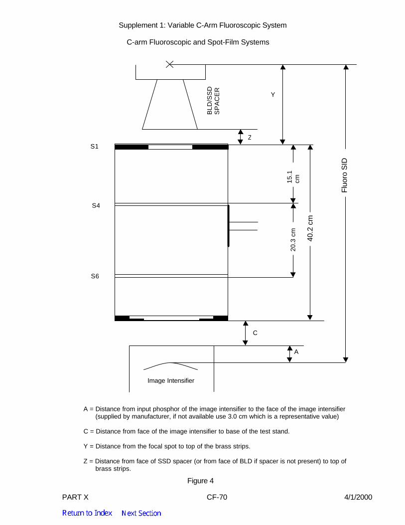
PART X CF-70 4/1/2000
Supplement 1: Variable C-Arm Fluoroscopic System C-arm Fluoroscopic and Spot-Film Systems
A = Distance from input phosphor of the image intensifier to the face of the image intensifier(supplied by manufacturer, if not available use 3.0 cm which is a representative value)
C = Distance from face of the image intensifier to base of the test stand.
Y = Distance from the focal spot to top of the brass strips.
Z = Distance from face of SSD spacer (or from face of BLD if spacer is not present) to top ofbrass strips.
Figure 4
S1
S4
S6
C
A
Z
Y
BLD
/SS
DS
PA
CE
R
15.1
cm20
.3 c
m
Fluo
ro S
ID
40.2
cm
Image Intensifier