c band sspa for communication satellites
TRANSCRIPT


SOLID STATE POWER AMPLIFIER (SSPA)
SAC Product Catalogue
C Band SSPA for Communication Satellites Ku-Band SSPA for Beacon of Satellites
C band SSPA
A large percentage of GEOSAT transponders operate at C
band, serving diverse applications like VSAT networks,
telecoms, television relay etc. A typical C band payload
would carry from twelve to twenty four numbers of normal
C band SSPAs.
The indigenously developed and well-proven 15 W att SSPA
technology will therefore be a recurr ing requirement in the
years to come.
Heritage: GSAT 7
Specifications
• Operating Frequency : 3700 – 4200 MHz
• Nominal RF Output Power : 15 W
• Large Signal Gain : 83 – 86 dB
• Mass : < 1 .7 Kg
• Dimensions : 209 x 110 x 96 mm
• Temperature range (Qualification) : -10 C to 60 C
Features
• Integral EPC
• Tele-commandable Attenuation for on-board gain setting
• Thermally painted chassis for optimal heat balance
Applications like DTH broadcasting, tele-education, telemedicine etc
have dr iven a growing demand for Ku Band transponders. A typical
Ku-band payload would carry two such Ku-Band Beacon SSPAs to
enable tracking the spacecraft from ground stations.
Heritage
Flown in almost all Ku band satellites dur ing the last several years.
Specifications
• Operating Frequency : 11700 5 MHz
• Nominal RF Output Power : 24 dBm
• Efficiency : 32 %
• Gain : 24 dB (min.)
• Mass : 1 kg.
• Dimensions : 206 x 140 x 25 .5 mm
• Temperature range : -5 C to +55 C
Features
• Dual SSPAs in single package
• Tele-commandable Attenuation for on-board gain setting
• Thermally painted chassis for optimal heat balance
Ku-Beacon SSPA

SOLID STATE POWER AMPLIFIER (SSPA)
UHF Band SSPA for Mobile Communication Satellites
The indigenously designed and developed state of the ar t 100W UHF
SSPA has been successfully deployed in GSAT-7 .
Heritage: GSAT 7
Specifications
• Operating Frequency : 242 – 255 MHz
• Nominal RF Output Power : 100 W
• Large Signal Gain : 100 dB
• Efficiency : 32 %
• Output Power Limiting (ALC): 120 W
• 3 rd order IMD @ 5 tone : -17 dBc
• Mass : < 6 .4 Kg (Integrated SSPA)
• Temperature range : -5 C to 55 C
Mechanical Configuration
• High Power Amplifier (350 x 200 x 27 mm 3)
• + Medium Power Amplifier (212 x 109 x 70 mm 3)
• + Electronic Power Conditioner (339 x108 x 229 mm 3)
Features
• Integral EPC
• Output Power Telemetry (Analog Voltage)
• Over Power Protection Mechanism
• Tele-commandable Attenuation for onboard gain setting
• Multi-Carr ier Operation (5 )
100W UHF SSPA with EPC
RF Section of UHF SSPA

SAC Product Catalogue
L-band DA for Navigation Satellites S Band DA for Communication Satellites
Navigational signals are transmitted on L-Band besides
the S-Band. Each IRNSS spacecraft would contain two L-
Band Dr iver Amplifiers as par t of the transmitter .
Heritage: IRNSS-1A, 1B
Specifications
• Operating Frequency : 1175 15 MHz
• Gain : 45 dB (min)
• Telecommand : 12 dB
• Mass : 600 gms
• Dimensions : 150 x 42 x 90 mm3
• Temperature : -5 C to +55 C
Features
• Dual DA in single package
• Tele-commandable Attenuation
• Thermally painted chassis for optimal heat balance
Mobile telecom and multimedia services on S-Band are expected to
grow in importance. The indigenously developed S-Band Dr iver Amplifier
is high output power amplifier specially design for applications like
GSAT-6 .
Heritage: GSAT-6
Specifications
• Operating Frequency : 2550 - 2600 MHz
• Band W idth : 50 MHz
• Gain : 56 dB (min)
• Linear O/ P power : 16 dBm
• Overdr ive : 12 dB
• Mass : 600 gms
• Dimensions : 153 x 43 x 81 mm3
• Temperature : - 5 C to + 55 C
Features
•· High gain & high output power
•· Tele-commandable Attenuation for Gain setting
•· Temperature Compensation
L-Band Driver Amplifier
S-Band Driver Amplifier
DRIVER AMPLIFIERS (DA)

SOLID STATE POWER AMPLIFIER and DRIVER AMPLIFIER
S-Band DA for Navigational Satellites C band SSPA for Navigational Satellites
This amplifier is used in the S-Band transmitter which
provides navigational data for the user receiver . Each
IRNSS spacecraft would use two of these Dr iver
Amplifiers.
Heritage: IRNSS-1A, 1B
Specifications
• Operating Frequency : 2492 15 MHz
• Gain : 45 dB (min)
• Command. Attenuator : 12 dB
• Mass : 600 gms
• Dimensions : 184 x 47 x 82 mm3
• Temperature range : -5 C to +60 C
Features
• Dual DA in single package
• Tele-commandable Attenuation for on-board gain
setting
• Thermally painted chassis for optimal heat balance
The IRNSS spacecraft is equipped with a ranging transponder to
help fix its position. This C-Band ranging payload would two normal
C-Band SSPAs.
Heritage: IRNSS-1A, 1B
Specifications
• Operating Frequency : 3 .4 – 3 .425 GHz
• RF Output Power : 5 W
• Gain : 78 dB (min)
• Command. Attenuator : 12 dB
• Total Phase Shift : 22 deg max.
• Overdr ive : 20 dB
• Mass : 1200 gms
• Dimensions : 185 x 145 x 135 mm3
• Temperature range : - 5 C to +55 C
Features
• Integral EPC & DA
• Tele-commandable Attenuation for on-board gain setting
• Thermally painted chassis for optimal heat balance
C-Band SSPA
S-Band Driver Amplifier
SAC Product Catalogue
ISRO is building up a constellation of IRNSS spacecrafts that will provide time, frequency and positioning services. A number of subsystems have been developed for
this program, which will be used in large numbers. Some of these are shown here.

DRIVER AMPLIFIERS (DA)
Ku-Band ALC DA for Communication Satellites Ku-band ALC DA for Communication Satellites
The lower photograph shows the well proven amplifier design
that has been used for several years.
Heritage: INSAT-4CR
Specifications
• Operating Frequency : 11450 – 11700 MHz
• Band W idth : 250 MHz
• Gain : 44 dB (min)
• Command. Attenuator : 22 dB
• ALC Range : 20 dB
• Input Overdr ive power : - 4 dBm (max.)
• Mass : 450 gms
• Dimensions : 112 x 42 x 90 mm3
• Temperature range : -10 C to +60 C
Features
• Both operational mode FGM & ALC
• Driver Amplifier with 20dB ALC range
• Vertical mounting to reduce foot pr int on panel
• Tele-commandable Attenuation for on-board gain setting
• Thermally painted chassis for optimal heat balance
On the top is a dual dr iver amplifier with improved mechanical
design.
Heritage: GSAT-8 & GSAT-10
Specifications
• Operating Frequency : 11450 – 11700 MHz
• Band W idth : 250 MHz
• Signal Gain : 44 dB (min)
• Command. Attenuator : 22 dB
• ALC Range : 20 dB
• Input Overdr ive power : -4 dBm (max.)
• Mass : 900 gms.
• Dimensions : 200 x 85 x 47 mm3
• Temperature range : -10 C to +60 C
Features
• Dual DA in single package with 20dB ALC range
• Both operational mode FGM & ALC
• Tele-commandable Attenuation for on-board gain setting
• Thermally painted chassis for optimal heat balance Ku-Band ALC Driver Amplifier
Ku-Band ALC Driver Amplifier
Direct-to-Home (DTH) television is one major application of GEOSAT Ku band satellites. To ensure good signal quality in all the weather conditions,
Automatic Level Control (ALC) driver amplifiers have been developed, of which 12 to 24 units are found on any satellite.
SAC Product Catalogue

Ku-band MMIC DA for Communication Satellites C-Band Lineariser for Communication Satellites
Ku-Band MMIC Driver Amplifier
DRIVER AMPLIFIER and LINEARISERS
MMIC based Ku-band dr iver amplifier is third generation of
Dr iver Amplifier . Besides being low weight and card-size
compact, the unit promises immense capabilities such as a
wideband operation and high ALC dynamic range.
Heritage
This Dr iver Amplifiers are under qualifications for future Ku-
Band satellites.
Specifications
• Operating Frequency : 10 .75 to 12 .75 GHz
• Band W idth : 2 GHz
• Gain : 44 dB (min)
• Gain Flatness : 0 .3 dB (any 40 MHz)
0 .8 dB (250 MHz)
• Command. Attenuator : 30 dB
• ALC Range : 20 dB
• Input Overdr ive power : -4 dBm (max.)
• Mass : 200 gms
• Dimensions : 122 x 17 x 55 mm3
• Temperature range : -10 C to +60 C
Features
• High dynamic Range: 30 dB
• Tele-commandable Attenuation for on-board gain setting
• Thermally painted chassis for optimal heat balance
• Hermetically sealed MMIC package
The indigenously developed C-Band Linear izer is compact and
efficient to linear ize the TW T Amplifier by adding reverse
distor tion character istics at the input of the TW T amplifier . It
has unique capability to nullify up to 10 dB AM/ AM and 50
degree AM/ PM component of the TW TA.
Heritage: Qualified and will be used in high power transponders
future C-Band satellites.
Specifications
• Operating Frequency : 3700 - 4200 MHz
• Gain : 14 dB
• Gain Expansion : 10 dB
• Phase Expansion : 50 Deg.
• Mass : 200 gms.
• Dimensions : 133 x 43 x 49 mm3
• Temperature : - 5 C to +55 C
Features
• Limiter for overdr ive protection
• Compact & light weight
• Easily tunable anywhere within the full C-band
C-Band Linearizer
Pre-distortion Linearisers are used to improve the Quality of Service by compensating for distortion in Power Amplifiers.
SAC, Ahmedabad has designed a series of Linearisers at L, S, C and Ku Bands.

LINEARISERS
Ku-Band Lineariser for Communication Satellites. S/L Band Lineariser for Navigation Satellites
Ku-Band Lineariser
S/ L-Band Lineariser
Heritage: IRNSS-1A, 1 B
Specifications
• Operating Frequency : 2492 15 MHz (S-Band)
: 1176 15 MHz (L-Band)
• Gain : 14 dB
• Gain Expansion : 10 dB
• Phase Expansion : 50 Deg.
• Mass : 120 gms.
• Dimensions : 102 x 17 x 58 mm3
• Temperature : - 5 C to +55 C
Features
• Limiter for overdr ive protection
• W ide band design can be tuned for L or S-band
• Compact & light weight
• Thermally painted chassis for optimal heat balance
Heritage: Qualified and will be used in high power
transponders of future Ku-Band satellites
Specifications
• Operating Frequency : 10500 – 12700 MHz
• Gain : 10 dB
• Gain Expansion : 10 dB
• Phase Expansion : 50 Deg.
• Mass : 120 gms
• Dimensions : 100 x 17 x 54 mm3
• Temperature : - 5 C to +55 C
Features
• Limiter for overdr ive protection
• Compact & light weight
• Easily tunable anywhere within entire Ku-band
SAC Product Catalogue

RECEIVERS (Rx)
Cext-Band MMIC Rx for Communication Satellites Cext-Band MMIC Rx for Communication Satellites
The indigenously developed Cext- band receiver is now a
proven technology for all its C band communication
satellites.
Heritage: This SSPA is already flown in INSAT-4CR satellite
and they are working to the best of the per formance.
Specifications
• Input Frequency : 6450 – 6690 MHz
• Output Frequency : 3425 – 3665 MHz
• Band W idth : 240 MHz
• Nominal Input power : -75 to -57 dBm
• Linear Gain : 50 ~ 53 dB
• Input Overdr ive power : -37 dBm (max.)
• Two tone IM3D @ -60 dBm : -44 dBc
• Mass : 450 gms
• Dimensions : 112 x 42 x 90 mm3
• Temperature range : -5 C to +60 C
Features
• W ith LNA auxiliary output
• Thermally painted chassis for optimal heat balance
The indigenously developed Cext- band receiver is now a proven
technology for all its C-Band communication satellites.
Heritage: This SSPA is already flown in GSAT-8 & GSAT-10 satellites
and they are working to the best of the per formance.
Specifications
• Input Frequency : 6450 – 6690 MHz
• Output Frequency : 3425 – 3665 MHz
• Band W idth : 240 MHz
• Nominal Input power : -51 to -33 dBm
• Linear Gain : 27 ~ 29 dB
• Input Overdr ive power : -13 dBm (max.)
• Two tone IM3D @ -33 dBm : -44 dBc
• Mass : 450 gms
• Dimensions : 112 x 42 x 90 mm3
• Temperature range : -5 C to +60 C
Features
• W ithout LNA
• Thermally painted chassis for optimal heat balance
Cext-Band MMIC Receiver
Cext-Band MMIC Receiver

SAC Product Catalogue
Ku-Band MMIC Rx for Communication Satellites Ku-Band Rx for Communication Satellites
Ku-Band MMIC Receiver
Ku-Band Receiver
RECEIVERS (Rx)
The indigenously developed MIC based Ku--Band Receiver is now a
proven technology for all its Ku-Band communication satellites.
Heritage: This receivers already flown in GSAT-3 , INSAT-4A,4B
satellite and they are working to the best of the per formance.
Specifications
• Input Frequency : 14000 – 14250 MHz
• Output Frequency : 10950 – 11200 MHz
• Translation Frequency : 3050 MHz
• Linear Gain : 55 ~ 57 Db
• Noise figure : 2 .5 dB
• Nominal Input power : - 75 dBm
• Two tone IM3D @ -62 dBm : - 44 dBc
• Mass : 1700 gms
• Dimensions : 120 x 80 x 90 mm3
• Temperature range : - 5 C to +60 C
Features
• Thermally painted chassis for optimal heat balance
The indigenously developed MMIC based Ku--Band Receiver
is now a proven technology for all its Ku-Band communication
satellites.
Heritage: This receivers are already flown in GSAT-7 satellite
and they are working to the best of the per formance.
Specifications
• Input Frequency : 14000 – 14250 MHz
• Output Frequency : 10950 – 11200 MHz
• Translation Frequency : 3050 MHz
• Nominal Input power : -75 dBm
• Linear Gain : 55 ~ 57 dB
• Noise figure : 2 .0 dB
• Two tone IM3D @ -62 dBm : -44 dBc
• Mass : 1500 gms
• Temperature range : -5 C to +60 C
• Dimensions : 120 x 50 x 90 mm3
Features
• Thermally painted chassis for optimal heat balance

DIPLEXERS
Transmit – Receive Diplexers
SAC has an extensive exper ience in the field of satellite filters. A multitude of Tx-Rx
diplexers from L to Ka-band and frequencies of up to 30 GHz have been designed,
manufactured and qualified in var ious programs in the last 30 years. The function
of the Tx-Rx diplexer is the separation of receive and transmit bands served by
one polar ization of a dedicated antenna.
Specifications
• Inser tion Loss: < 0 .15 dB over temperature range
• Rejection over Receive Band: > 60 dB
• Power handling capability: Up to 140 W / CH in Ku-Band,
40W / CH in L-Band and 60 W / CH in C-band.
Features
• The diplexers are realized using low pass-band pass filter combination.
• The Tx filter is a stepped impedance low pass filter realized using corrugated
waveguide sections. The receive filter is a Chebyshev BPF realized using
inductive ir is coupled waveguide resonators.
• The diplexers are realized without the use of tuning screws, which can
degrade multipaction threshold and generate PIM.
• The diplexers are fabr icated from aluminium alloy by cutting it in to two
halves and clamping them together & silver plated internally
• The designs have met all the structural requirements of payloads where the
stiffness is greater than 12 5 Hz and the maximum temperature is found to
be 98 0C.
Performance
• Low inser tion loss (<0 .15 dB)
• Good Return Loss (>26 dB)
• High receive/ transmit isolation of > 60 dB
• Flat amplitude and group delay response
• High power handling capability
• – Low dissipated power (Good thermal design)
• No generation of passive inter -modulation products (Tested up to –150 dBm)
L-Band Tx/Tx
Diplexer
Ku-Band Tx/Rx
Diplexer
C-Band Tx/Tx
Diplexer

SAC Product Catalogue
Ku-Band Output Multiplexers
MULTIPLEXERS
Features
• Channel Filters realized using 5 -Pole Quasi elliptic filter ing function
• Channel Filters in 7 -Channel OMUX operates in TE113 resonant mode
• Channel Filters in 6 -Channel OMUX operates in TE114 resonant mode
• Channel Bandwidth = 36 MHz Average Power Handling = 140 W per Ch.
• Peak Power Handling (n2Pi)=5 .04 kW
• Channel Filters are combined using Manifold Multiplexing technique
• Manifold realized using full height W R75 waveguide
• Filters & Manifold waveguides constructed from silver plated Super Invar
mater ial for temperature stability & best possible quality factor
SAC has an extensive exper ience in the field of satellite filters. A multitude of filters
and multiplexers from L- to Ka-band and frequencies of up to 30 GHz have been
designed, manufactured and qualified in var ious programs in the last 30 years. The
function of the Output Multiplexer is to recombine the var ious downlink channel
frequency bands into a broadband signal after amplification. A typical output
multiplexer used in spacecraft communication payload consists of channel filters and
a common manifold.
Specifications
• Inser tion Loss: <0 .75 dB over temp. range
• Rejection: >30 dB
• Power handling capability: Up to 140 W atts
Performance
• Extremely low loss channel filter design
• Q > 15000
• Measured ELFD < 0 .4 ppm / 0C
• High power handling capability and low PIM level designs
• Design ver ification by test up to 30 kW
Ku-Band 6 CH OMUX Ku-Band 7 CH OMUX
Ku-Band 13 Ch OMUX

FILTERS
Helical Band Pass Filters
SAC has an extensive exper ience in the field of satellite filters. Helical Resonators
based filters from 20 0 to 800 MHz have been designed, manufactured and
qualified in var ious mission programmes in the last 20 years. These are most
suitable type of filters in VHF/ UHF Band consider ing size, weight, Inser tion loss
and out of band rejection parameters & widely used in communication payload
subsystems. The functions of the Helical Resonators based filters are as Pre
Select Filter , Image Reject BPF in Receiver at UHF, for harmonic rejection after
Multipliers in Local Oscillators.
Specifications
• Centre Frequency range: 200 to 800 MHz
• Inser tion Loss range: <1 to 5 dB over temp. range
• 3 dB Bandwidth range for different types are: 2 .1 MHz to 60 MHz
• Flatness: < 1 dB
• I/ P & O/ P Impedance: 50 Ohm
Features
• Helical Filters realized using 3 -Pole,4 -Pole & 5 -pole having Butterworth &
Chebyshev filter ing function
• Small size & compact
• Light weight
• I/ P & O/ P inter face SFT Pin or SMA (F)
• Filters constructed from silver plated Aluminium mater ial & for Helix Teflon
supports for best possible quality factor
• Outer sur face finish Black paint/ Anodized
Performance
• Extremely compact with low loss filter design
• PCB mountable & SMA connector version

SAC Product Catalogue
Cext Upper band Harmonic Rejection Filter
FILTERS
C-ext upper Harmonic Rejection Filter is a low pass filter used at the output
of C ext upper OMux. It provides rejection of > 60 dB over receive
frequency range and at second and third harmonic frequencies. It is a 9 -
section stepped impedance corrugated waveguide low pass filter .
Specifications
• Frequency band: 4500 – 4800 MHz
• Inser tion Loss: <0 .10 dB
• Input / Output Return loss: >20 dB
• Operating Temperature: -15 to 60 deg C
Ku band Harmonic Rejection Filter
Ku-Band 12 GHz Harmonic Rejection Filter is used for Tx frequency range
of 10 .95 -11 .7 GHz. It provides rejection of > 60 dB over receive frequency
range of 13 .75 -14 .5 GHz and at second and third harmonic frequencies. It
is a 9 -section stepped impedance corrugated waveguide low pass filter .
Cr it ical gaps in the HRF are designed such that it has multipaction
threshold of > 1 .2 KW .
Specifications
• Frequency band: 10950 – 11700 MHz
• Inser tion Loss: <0 .20 dB
• Input / Output Return loss: >20 dB
• Operating Temperature: -15 to 60 deg C

FILTERS
Ku band PIM Filter
The PIM filter is a stepped impedance corrugated waveguide low pass filter .
The filter is realized without the use of tuning screws. The filter is fabr icated
in two halves & clamped together with grooved joints to generate high
contact pressure. The filter is silver plated internally to achieve lowest
possible inser tion loss and also have low PIM generation. The Ku-band PIM
filter suppresses the PIM signals generated by high power carr iers in the
10 .95 -11 .7 GHz from falling in 13 .75 -14 .5 GHz by more than > 60 dB. The
PIM performance of the filter itself should be <-175 dBc. The gaps in the
filters are sufficiently large to achieve the required multipaction threshold of
5 .04 kW .
Specifications
• Frequency range: 10950 – 11700 MHz
• Inser tion Loss range: < 0 .15 dB
• Operating Temperature: - 15 to 60 deg C
• Input / Output Return Loss: > 20 dB
UHF band PIM FILTER
PIMP filter is realized as a Band-stop filter as it provides better rejection in
the stop-band compared to a low-pass filter , for a given no. of sections. It
is a 4 -pole filter and consists of a tx line coupled to quarter wavelength Tx
lines resonating at Rx frequency. Teflon is filled between inner and outer
conductors to avoid multipaction. The unit was tested for a peak power of
1 .5 KW and was multipactor free at both the temperature extremes of the
operating temperature.
Specifications
• Frequency range: 242 .1– 254 .7 MHz
• Inser tion Loss range: < 0 .10 dB
• Operating Temperature: - 40 to 80 deg C
• Input / Output Return Loss: > 20 dB
SAC Product Catalogue
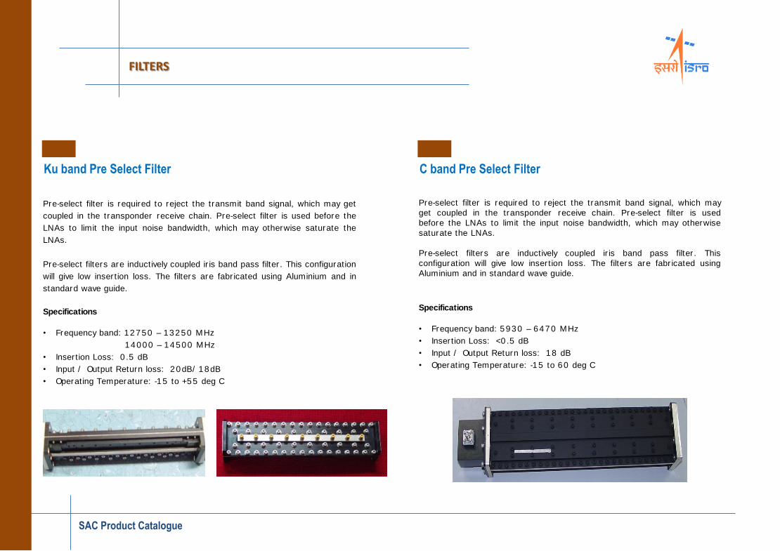
Ku band Pre Select Filter
FILTERS
Pre-select filter is required to reject the transmit band signal, which may get
coupled in the transponder receive chain. Pre-select filter is used before the
LNAs to limit the input noise bandwidth, which may otherwise saturate the
LNAs.
Pre-select filters are inductively coupled ir is band pass filter . This configuration
will give low inser tion loss. The filters are fabr icated using Aluminium and in
standard wave guide.
Specifications
• Frequency band: 12750 – 13250 MHz
14000 – 14500 MHz
• Inser tion Loss: 0 .5 dB
• Input / Output Return loss: 20dB/ 18dB
• Operating Temperature: -15 to +55 deg C
C band Pre Select Filter
Pre-select filter is required to reject the transmit band signal, which may
get coupled in the transponder receive chain. Pre-select filter is used
before the LNAs to limit the input noise bandwidth, which may otherwise
saturate the LNAs.
Pre-select filters are inductively coupled ir is band pass filter . This
configuration will give low inser tion loss. The filters are fabr icated using
Aluminium and in standard wave guide.
Specifications
• Frequency band: 5930 – 6470 MHz
• Inser tion Loss: <0 .5 dB
• Input / Output Return loss: 18 dB
• Operating Temperature: -15 to 60 deg C

3 dB Quadrature Hybrid Coupler
COUPLERS
Features
• Hybr id couplers are realized using var ious approaches i.e. branch line, lange
patterns etc
• Mode of operation is quasi TEM
• W idely used for combining and splitt ing operations and also provide
redundancy in different subsystems.
• Var ious operational fractional bandwidths star ting from 8% to 53%
SAC has developed var ious class of modern communication systems and Quadrature
couplers which remained an integral par t of the system development. A wide range
of frequency spectrum is covered star ting from UHF band (375MHz) to Ka-band
(28GHz). The Quadrature couplers are having a strong her itage of use in var ious
INSAT/ GSAT projects and still evolving as per the requirement. Lesser weight and
super ior per formance is an inevitable requirement and has to be maintained as
better as possible.
Specifications
• Frequency: UHF, S, C, Ku and Ka bands
• Inser tion Loss: <1 .5 dB over temp. range
• Amplitude imbalance: <0 .5 -0 .8dB
• Return loss: >17 dB
• Isolation: >17 dB
• Phase Imbalance: <5 º
Performance
• An up to date design with high end per formance
• W ideband temperature (-22 ºC to 65 ºC) stability
• W ide communication band coverage
UHF/ S/ C band Coupler Ku band transmit Coupler Ka band Coupler