c copyright 2011 elsevier notice changes introduced … · 57 nester et al., 2007, leardini et al.,...
TRANSCRIPT

This is the author’s version of a work that was submitted/accepted for pub-lication in the following source:
Bishop, Chris, Paul, Gunther, & Thewlis, Dominic(2011)Footwear modifies foot and ankle kinematics during stance phase of walk-ing gait.Journal of Science and Medicine in Sport, 14(Sup1), e39-e40.
This file was downloaded from: https://eprints.qut.edu.au/49111/
c© Copyright 2011 Elsevier
This is the author’s version of a work that was accepted for publication in Journal of Sci-ence and Medicine in Sport. Changes resulting from the publishing process, such aspeer review, editing, corrections, structural formatting, and other quality control mecha-nisms may not be reflected in this document. Changes may have been made to this worksince it was submitted for publication. A definitive version was subsequently published inJournal of Science and Medicine in Sport, [VOL: 14, ISSUE: Supplementary, (2011)] DOI:10.1016/j.jsams.2011.11.082
Notice: Changes introduced as a result of publishing processes such ascopy-editing and formatting may not be reflected in this document. For adefinitive version of this work, please refer to the published source:
https://doi.org/10.1016/j.jsams.2011.11.082

For Peer Review O
nly
A radiological method to determine the accuracy of motion
capture marker placement on palpable anatomical landmarks through a shoe
Journal: Footwear Science
Manuscript ID: Draft
Manuscript Type: Original Article
Keywords: Anatomical markers, Reliability, Kinematic model, X-ray, footwear, Foot & ankle
URL: http:/mc.manuscriptcentral.com/tfws Email: [email protected]
Footwear Science

For Peer Review O
nly
Manuscript Title: A radiological method to determine the accuracy of motion capture marker 1
placement on palpable anatomical landmarks through a shoe 2
3
Abstract 4
The accuracy of marker placement on palpable surface anatomical landmarks is an important 5
consideration in biomechanics. Although markers may be able to be applied consistently in the same 6
position on the foot between rater’s or sessions, it remains unknown whether these markers accurately 7
reflect the location of the underlying anatomical landmark they are intended to represent. A novel 8
method was developed to identify the accuracy of markers placed on the shoe surface by palpating 9
landmarks through the shoe. An anterior-posterior and lateral-medial x-ray were taken on 24 10
participants with a custom marker set applied to both the skin and shoe. The vector magnitude of both 11
skin and shoe mounted markers from the anatomical landmark was calculated, as well as the mean 12
marker offset between skin and shoe mounted markers. The mean difference in displacement of 13
the shoe mounted marker relative to the skin mounted marker, accounting for shoe thickness, 14
was less than 10 mm for all markers studied. Further, when using the developed guidelines 15
provided in this study, the method was deemed reliable (Intra-rater ICC’s = 0.61-0.96). In 16
addition to proposing a method to determine marker placement accuracy, this paper also 17
provides a series of offsets to account for shoe-marker thickness in an in-shoe kinematic 18
model. 19
20
21
22
23
24
25
26
27
Page 1 of 19
URL: http:/mc.manuscriptcentral.com/tfws Email: [email protected]
Footwear Science
123456789101112131415161718192021222324252627282930313233343536373839404142434445464748495051525354555657585960

For Peer Review O
nly
Keywords 28
Anatomical markers; Kinematic Model; X-ray; Reliability; Foot and ankle 29
30
31
32
33
34
35
36
37
38
39
40
41
42
43
44
45
46
47
48
49
50
51
52
Page 2 of 19
URL: http:/mc.manuscriptcentral.com/tfws Email: [email protected]
Footwear Science
123456789101112131415161718192021222324252627282930313233343536373839404142434445464748495051525354555657585960

For Peer Review O
nly
Background 53
Kinematic marker sets are commonly used to quantify the foot and ankle mechanics during 54
gait and have interchangeably been applied to both the skin surface of the foot and on the 55
shoe surface with little consideration for accuracy in the latter condition (Carson et al., 2001, 56
Nester et al., 2007, Leardini et al., 2007, Cheung and Ng, 2007, Stacoff et al., 1992, Nigg and 57
Morlock, 1987, Lundgren et al., 2008). The markers are intended to define anatomical frames 58
that allow for the description of joint kinematics (Cappozzo et al., 1995). The focus of the 59
majority of the literature over the past twenty years has been on reliability. It is widely 60
accepted that the intra-rater reliability of marker application is good (Kadaba et al., 1989), yet 61
the largest source of marker placement variation is found between raters from different 62
laboratories (Gorton et al., 2009). 63
64
While reliability is essential, it is seemingly worthless if the accuracy of the anatomical frame 65
is defined incorrectly, as marker placement errors as small as 10 mm have been shown to 66
significantly alter joint moments (Thewlis et al., 2008, Holden and Stanhope, 1998). Where 67
reliability analyses will show whether marker researchers and scientists can place markers in 68
the same position, it gives no information in regards to whether the markers are placed on the 69
anatomical landmark of interest. Achieving acceptable marker placement accuracy may be 70
enhanced with strict adherence to guidelines designed to improve the consistency in 71
identifying anatomical landmarks on the skin surface (Van Sint Jan, 2007). Inaccuracies in 72
marker placement as small as 10 mm are conceivable at large joints; however this problem is 73
much aggravated for feet covered by shoes. The relatively small surface area and close 74
proximity of palpable anatomical landmarks on the foot presents a problem where marker 75
misplacement is a genuine possibility. 76
77
Page 3 of 19
URL: http:/mc.manuscriptcentral.com/tfws Email: [email protected]
Footwear Science
123456789101112131415161718192021222324252627282930313233343536373839404142434445464748495051525354555657585960

For Peer Review O
nly
This paper presents a method we have developed to quantify the accuracy of marker 78
placement on palpable anatomical landmarks of the foot through shoes. The paper will also 79
develop a set of offset values for the compensation of shoe thickness in models used to 80
investigate in-shoe foot kinematics. 81
82
Methods 83
This study was approved by the Human Research Ethics Committee, University of South 84
Australia. Twenty-four participants (mean age of 22.4 yrs (SD = 4.8 yrs), height of 1.79 m 85
(SD = 0.10 m) and body mass of 75.8 kg (SD = 13.4 kg)) were recruited to the study. An 86
weight bearing anterior-posterior and lateral-medial x-ray were taken of a marker set (seven x 87
10 mm markers [Figure 1]) affixed to each participant in two experimental conditions: 88
barefoot [A] and shod [B]. A basic structured shoe (Mexico 66, ACICS Corporation, Japan) 89
consisting of an outsole, midsole and upper was used. A Shimadzu Computer Radiography 90
(CR) machine (Shimadzu, Japan) was used to take all x-rays. 91
92
To take the weight-bearing A-P view, the participant stood on the floor with their feet on the 93
CR x-ray plate. The x-ray tube was angled at 20˚ to the perpendicular line coming from the 94
floor. The source-image distance (SID) used was 1.0 m. To take the lateral-medial view, the 95
participant stood on a raised platform, with the CR cassette mounted between the two feet. 96
This ensured even distribution of the centre of mass over the base of support. The x-ray beam 97
was (perpendicular) to the foot sagittal plane. The source-image distance used was 100 cm. 98
The data was automatically digitised by computational software (Voyager PACS digitization 99
software, 3.2 Release 7 Build 3, Voyager Imaging, Australia) and provided for analysis as 100
raw, unidentified, digital imaging and communications in medicine (DICOM) files. The 101
exposure settings used (A-P View – 5 mAs and 55 kVp and lateral-medial view – 5 mAs and 102
Page 4 of 19
URL: http:/mc.manuscriptcentral.com/tfws Email: [email protected]
Footwear Science
123456789101112131415161718192021222324252627282930313233343536373839404142434445464748495051525354555657585960

For Peer Review O
nly
59 kVp) ensured the correct contrast and density of image was obtained. The two x-ray 103
images were calibrated with a standard reference object. The 2D positions of each marker and 104
corresponding anatomical landmark were manually digitised in Matlab (Matlab 2010b, 105
Mathworks, USA) following custom guidelines (Appendix 1). This was repeated for each 106
experimental condition on both the A-P and lateral-medial x-ray images. 107
108
To assess the accuracy of marker placement, the vector magnitude between the underlying 109
anatomical landmark and each of the skin (d1) and shoe mounted (d2) markers was calculated. 110
The vector magnitude between the skin and shoe mounted markers was also calculated (d3), 111
which was assumed to be a measure of shoe thickness. The adjusted measure of shoe mounted 112
marker displacement (d4) was defined as the vector magnitude between the anatomical 113
landmark and shoe mounted marker minus the vector magnitude between the two markers. 114
The mean shoe marker offset (MMO) was calculated as the adjusted shoe mounted marker 115
displacement minus the vector magnitude between the anatomical landmark and skin mounted 116
marker (Figure 2). The MMO was considered a medial-lateral offset on the A-P x-ray image 117
and a superior-inferior offset on the lateral-medial image. The MMO was assumed to be a 118
direct measure of shoe mounted marker placement accuracy. 119
120
Two independent researchers with a minimum of five years expertise working with foot and 121
ankle radiography identified the coordinates of markers separately, one week apart to analyse 122
both intra- and inter-rater reliability. Rater 1 re-identified marker positions one week later to 123
assess intra-rater reliability. Intra-class correlation coefficients were used as measures of 124
reliability of the method (Landis and Koch, 1977). 125
126
127
Page 5 of 19
URL: http:/mc.manuscriptcentral.com/tfws Email: [email protected]
Footwear Science
123456789101112131415161718192021222324252627282930313233343536373839404142434445464748495051525354555657585960

For Peer Review O
nly
Results 128
The results of the accuracy assessment indicate that shoe mounted markers were placed 129
further away from the anatomical landmarks compared to the equivalent skin mounted 130
markers (Table 1). On the A-P view, the greatest displacement of a shoe mounted marker 131
from an anatomical landmark was the styloid process (MMO = 6.9 mm). The mean marker 132
offset between all other markers was < 5 mm, which was equivalent to the radius of the 133
markers. On the lateral-medial view, the greatest displacement of a shoe mounted marker 134
from an anatomical landmark was the apex of the 2nd toe (MMO = 9.2 mm). Four markers 135
resulted in mean marker offsets of < 1 mm. The calculated mean marker offset also provides a 136
method to compensate for shoe thickness in an in-shoe model, with medial-lateral and 137
superior-inferior offset projections provided for each shoe mounted marker (Table 2). 138
139
In respect to the reliability of the method, the application of markers on the anterior-posterior 140
x-ray view resulted in strong to excellent intra-rater reliability (ICC = 0.61 – 0.96). The 141
application of markers on the lateral-medial x-ray view resulted in strong to excellent intra-142
rater reliability (ICC = 0.73 – 0.96). Inter-rater reliability ranged from moderate to excellent 143
on both the A-P view (ICC = 0.44 – 0.96) and the lateral-medial view (ICC = 0.45 – 0.83). 144
145
Discussion 146
This study presents a method to determine the accuracy of markers placed on either the skin 147
or shoe surface in relation to the underlying anatomical landmark they are purported to 148
represent. We present data pertaining to the measured accuracy of markers from the 149
underlying anatomical landmark as well as the reliability of the measurement protocol 150
proposed. The mean difference in displacement of the shoe mounted marker, accounting for 151
shoe thickness, was less than 10 mm for all markers studied. Previously proposed methods to 152
assess reliability focus on static marker placement, indicating that reliable marker placement 153
Page 6 of 19
URL: http:/mc.manuscriptcentral.com/tfws Email: [email protected]
Footwear Science
123456789101112131415161718192021222324252627282930313233343536373839404142434445464748495051525354555657585960

For Peer Review O
nly
can result in consistent joint kinematics. However, this paper presents a novel method using 154
radiology designed to quantify the accuracy of motion capture marker placement on palpable 155
anatomical landmarks through a shoe. 156
157
This study has established that when using the developed guidelines (Appendix 1), the 158
method is reliable. In the participants used in this study, the method identified that the 159
application of markers was accurate to < 10 mm with respect to the underlying anatomical 160
landmark. 161
162
When accounting for shoe thickness, the application of shoe mounted markers resulted in sub-163
millimetre accuracy in 43% of cases. The recorded accuracy was < 5mm in 78% of cases. The 164
large mean marker offsets demonstrated in respect to the forefoot markers on the lateral-165
medial x-ray image can be explained by the presence of the shoe toe box, whereby the dorsal 166
surface of the shoe does not directly articulate with the dorsal aspect of the toes. Despite this, 167
the high accuracy demonstrated in this study is testament to the strength and transparency of 168
the guidelines and methods proposed to assess the accuracy of marker placement on the shoe 169
overlying anatomical landmarks. 170
171
Although the development of this method is novel and provides a significant step forward in 172
footwear research, it does have its limitations. The proposed method may prove to be more 173
difficult in the presence of a more structured shoe (i.e. heel counters), especially given the 174
likelihood of increased difficultly in palpating anatomical landmarks through rigid shoe 175
componentry. Furthermore, this method managed the accuracy individually in the sagittal and 176
coronal planes. The lack of measured accuracy in the transverse plane limits the interpretation 177
and consequent validation of the dynamic displacement of markers in 3-D space. Future 178
Page 7 of 19
URL: http:/mc.manuscriptcentral.com/tfws Email: [email protected]
Footwear Science
123456789101112131415161718192021222324252627282930313233343536373839404142434445464748495051525354555657585960

For Peer Review O
nly
research utilising computer tomography (CT scans) will aid in the 3-D interpretation of 179
marker placement accuracy. Despite this limitation, the results presented can still inform 180
future development of in-shoe kinematic models, whereby the shoe thickness is accounted for 181
as either a medial-lateral or superior-inferior offset for true estimation of in-shoe foot segment 182
geometry and coordinate systems. 183
184
Conclusion 185
We have developed a reliable radiologic method that is capable of describing the accuracy of 186
markers placed on the surface of the shoe with reference to an underlying anatomical 187
landmark. As expected, all shoe mounted marker were placed further away from the 188
referenced anatomical landmark than their skin-mounted counterparts, yet when accounting 189
for shoe thickness, the mean marker offset of shoe mounted markers was less than 10 mm for 190
all markers. Based on the results of this study, the protocol described serves as an additional 191
tool for footwear researchers given its ability to determine the accuracy of markers placed on 192
either the skin or shoe surface in reference to the underlying anatomical landmark they are 193
intended to represent. 194
195
Acknowledgements 196
We would like to acknowledge ASICS Oceania for supplying the footwear used in this study and the 197
Medical Radiation Department, University of South Australia providing access to the radiology suite. 198
Ergolab is supported by AutoCRC and the South Australian Government. 199
200
201
202
203
204
Page 8 of 19
URL: http:/mc.manuscriptcentral.com/tfws Email: [email protected]
Footwear Science
123456789101112131415161718192021222324252627282930313233343536373839404142434445464748495051525354555657585960

For Peer Review O
nly
205
206
207
208
Appendix 1– Identification of Anatomical Landmarks on X-ray 209
Navicular Tuberosity 210
Lateral-Medial View A-P View 211
212
213
214
1st Metatarsal head 215
Lateral-Medial View A-P View 216
217
218
219
220
Identification of Apex of 1st Toe (hallux) 221
Lateral-Medial View A-P View 222
The navicular tuberosity on the lateral-
medial x-ray view is located in the
inferior-posterior corner of the navicular
bone
The navicular tuberosity on the A-P x-ray
view is located at the most medial point of
the navicular bone.
The 1st
metatarsal landmark on the lateral-
medial x-ray view is identified as the
median point on a line connecting the two
widest points of the 1st
metatarsal head.
The 1st
metatarsal landmark on the A-P x-
ray view is identified as the most medial
point of the 1st
metatarsal head.
Page 9 of 19
URL: http:/mc.manuscriptcentral.com/tfws Email: [email protected]
Footwear Science
123456789101112131415161718192021222324252627282930313233343536373839404142434445464748495051525354555657585960

For Peer Review O
nly 223
224
225
Identification of Apex of 2nd
Toe 226
Lateral-Medial View A-P View 227
228
229
230
231
Identification of 2nd
Metatarsal Head 232
Lateral-Medial View A-P View 233
234
235
236
237
Identification of 5th
Metatarsal Head 238
Lateral-Medial View A-P View 239
The Apex of the 1st
toe landmark on the
lateral-medial x-ray view is identified as the
most dorsal point of the distal 1st
phalanx.
The Apex of the 1st
toe landmark on the A-
P x-ray view is identified as the median
point on a line connecting the two widest
points of the distal 1st
phalanx.
The Apex of the 2nd
toe landmark on the
lateral-medial x-ray view is identified as the
most dorsal point of the distal 2nd
phalanx.
The Apex of the 2nd
toe landmark on the A-
P x-ray view is identified as the median
point on a line connecting the two widest
points of the distal 2nd
phalanx.
The 2nd
metatarsal head landmark on the
lateral-medial x-ray view is identified as the
most dorsal point of the 2nd
metatarsal head.
The Apex of the 2nd
toe landmark on the A-
P x-ray view is identified as the median
point on a line connecting the two widest
points of the 2nd
metatarsal head.
Page 10 of 19
URL: http:/mc.manuscriptcentral.com/tfws Email: [email protected]
Footwear Science
123456789101112131415161718192021222324252627282930313233343536373839404142434445464748495051525354555657585960
For Peer Review O
nly 240
241
242
Identification of Styloid Process 243
Lateral-Medial View A-P View 244
245
246
247
248
249
250
251
252
253
254
255
256
257
258
259
260
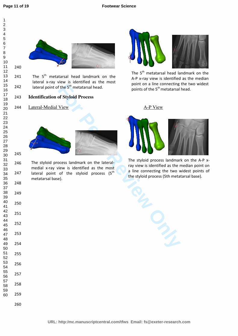
The 5th
metatarsal head landmark on the
lateral x-ray view is identified as the most
lateral point of the 5th
metatarsal head.
The 5th
metatarsal head landmark on the
A-P x-ray view is identified as the median
point on a line connecting the two widest
points of the 5th
metatarsal head.
The styloid process landmark on the A-P x-
ray view is identified as the median point on
a line connecting the two widest points of
the styloid process (5th metatarsal base).
The styloid process landmark on the lateral-
medial x-ray view is identified as the most
lateral point of the styloid process (5th
metatarsal base).
Page 11 of 19
URL: http:/mc.manuscriptcentral.com/tfws Email: [email protected]
Footwear Science
123456789101112131415161718192021222324252627282930313233343536373839404142434445464748495051525354555657585960

For Peer Review O
nly
Reference list 261
CAPPOZZO, A., CATANI, F., DELLA CROCE, U. & LEARDINI, A. 1995. Position and orientation in space of 262
bones during movement: anatomical frame definition and determination. Clinical Biomechanics, 10, 263
171-178. 264
CARSON, M. C., HARRINGTON, M. E., THOMPSON, N., O'CONNOR, J. J. & THEOLOGIS, T. N. 2001. 265
Kinematic analysis of a multi-segment foot model for research and clinical applications: A 266
repeatability analysis. Journal of Biomechanics, 34, 1299-1307. 267
CHEUNG, R. T. H. & NG, G. Y. F. 2007. Efficacy of motion control shoes for reducing excessive rearfoot 268
motion in fatigued runners. Physical Therapy in Sport, 8, 75-81. 269
GORTON, G. E., HEBERT, D. A. & GANNOTTI, M. E. 2009. Assessment of the kinematic variability 270
among 12 motion analysis laboratories. Gait & Posture, 29, 398-402. 271
HOLDEN, J. P. & STANHOPE, S. J. 1998. The effect of variation in knee center location estimates on 272
net knee joint moments. Gait & Posture, 7, 1-6. 273
KADABA, M. P., RAMAKRISHNAN, H. K., WOOTTEN, M. E., GAINEY, J., GORTON, G. & COCHRAN, G. V. 274
B. 1989. Repeatability of kinematic, kinetic, and electromyographic data in normal adult gait. Journal 275
of Orthopaedic Research, 7, 849-860. 276
LANDIS, J. R. & KOCH, G. G. 1977. The measurement of observer agreement for categorical data. 277
Biometrics, 33, 159-174. 278
LEARDINI, A., BENEDETTI, M. G., BERTI, L., BETTINELLI, D., NATIVO, R. & GIANNINI, S. 2007. Rear-foot, 279
mid-foot and fore-foot motion during the stance phase of gait. Gait and Posture, 25, 453-462. 280
LUNDGREN, P., NESTER, C., LIU, A., ARNDT, A., JONES, R., STACOFF, A., WOLF, P. & LUNDBERG, A. 281
2008. Invasive in vivo measurement of rear-, mid- and forefoot motion during walking. Gait & 282
Posture, 28, 93-100. 283
NESTER, C., JONES, R. K., LIU, A., HOWARD, D., LUNDBERG, A., ARNDT, A., LUNDGREN, P., STACOFF, 284
A. & WOLF, P. 2007. Foot kinematics during walking measured using bone and surface mounted 285
markers. Journal of Biomechanics, 40, 3412-3423. 286
Page 12 of 19
URL: http:/mc.manuscriptcentral.com/tfws Email: [email protected]
Footwear Science
123456789101112131415161718192021222324252627282930313233343536373839404142434445464748495051525354555657585960

For Peer Review O
nly
NIGG, B. M. & MORLOCK, M. 1987. The influence of lateral heel flare of running shoes on pronation 287
and impact forces. Medicine and Science in Sports and Exercise, 19, 294-302. 288
STACOFF, A., REINSCHMIDT, C. & STUSSI, E. 1992. The movement of the heel within a running shoe. 289
Medicine and Science in Sports and Exercise, 24, 695-701. 290
THEWLIS, D., RICHARDS, J. & BOWER, J. 2008. Discrepancies in knee joint moments using common 291
anatomical frames defined by different palpable landmarks. Journal of Applied Biomechanics, 24, 292
185-190. 293
VAN SINT JAN, S. 2007. Color Atlas of Skeletal Landmark Definitions: Guidelines for Reproducible 294
Manual and Virtual Palpations, Elsevier. 295
296
297
298
299
300
301
302
303
Page 13 of 19
URL: http:/mc.manuscriptcentral.com/tfws Email: [email protected]
Footwear Science
123456789101112131415161718192021222324252627282930313233343536373839404142434445464748495051525354555657585960

For Peer Review Only
Table 1 – Skin & Shoe Marker Displacement from Anatomical Landmark 304
Markers A-P View Lateral-Medial View
Skin-mounted Shoe-mounted Skin-mounted Shoe-mounted
Mean (mm) 95% CI (mm) Mean (mm) 95% CI (mm) Mean (mm) 95% CI (mm) Mean (mm) 95% CI (mm)
Navicular tub. 5.3 4.2 - 6.3 9.9 8.4 - 11.3 2.6 1.7 - 3.4 3.5 2.3 - 4.8
1st met. head 5.0 4.3 - 5.7 7.4 6.5 - 8.2 2.0 1.4 - 2.5 1.8 1.0 - 2.6
Apex 1st toe 2.1 1.2 - 2.9 2.2 0.6 - 3.9 3.8 2.7 - 5.0 9.6 8.1 - 11.1
Apex 2nd toe 4.1 3.3 - 4.9 4.0 2.4 - 5.6 5.6 4.1 - 7.2 14.5 12.2 - 16.7
2nd met. head 2.4 1.5 - 3.3 2.5 1.1 - 3.9 7.6 6.4 - 8.8 16.7 14.4 - 19.0
5th met. head 4.5 3.5 - 5.5 9.2 7.8 - 10.7 2.3 1.5 - 3.1 3.0 1.4 - 4.5
Styloid process 5.5 4.9 - 6.1 12.4 11.2 - 13.5 1.8 1.0 - 2.5 4.1 2.9 - 5.3
305
306
307
308
309
310
311
312
313
314
Page 14 of 19
URL: http:/mc.manuscriptcentral.com/tfws Email: [email protected]
Footwear Science
123456789101112131415161718192021222324252627282930313233343536373839404142434445464748495051525354555657585960

For Peer Review O
nly
Table 2 - Compensation for Shoe Thickness (Mean Marker Offset) 315
Marker Marker Offset
medial-lateral axis (mm) Dorsal-plantar axis (mm)
Navicular Tub. 5.4 3.9
1st met. head 2.7 2.5
Apex 1st toe 3.8 4.4
Apex 2nd toe 4.3 5.3
2nd met. head 7.3 3.8
5th met. head 10.7 4.5
Styloid process 11.1 5.6
316
317
318
319
320
321
322
323
324
325
326
327
328
329
330
331
332
333
334
335
336
337
338
339
340
341
342
343
344
345
346
347
348
349
350
351
352
353
354
355
356
Page 15 of 19
URL: http:/mc.manuscriptcentral.com/tfws Email: [email protected]
Footwear Science
123456789101112131415161718192021222324252627282930313233343536373839404142434445464748495051525354555657585960

For Peer Review O
nly
Table 3 – Reliability of Identification of Marker Placement 357
358
X-Ray View Marker Intra-rater Inter-Rater
ICC Abs Diff (mm) ICC Abs Diff (mm)
Anterior-Posterior
Navicular tub. 0.73 0.91 0.66 1.40
1st met. head 0.86 0.52 0.58 1.06
Apex 1st toe 0.74 0.62 0.88 0.38
Apex 2nd toe 0.61 0.23 0.44 0.85
2nd met. head 0.93 0.29 0.96 0.52
5th met. head 0.77 0.18 0.86 0.42
Styloid process 0.96 0.08 0.92 0.02
Lateral-Medial
Navicular tub. 0.96 0.12 0.8 1.63
1st met. head 0.78 0.17 0.63 0.49
Apex 1st toe 0.78 0.21 0.5 1.18
Apex 2nd toe 0.79 0.69 0.6 1.13
2nd met. head 0.88 0.25 0.45 1.63
5th met. head 0.92 0.13 0.83 0.09
Styloid process 0.73 0.37 0.49 0.14
Abs Diff – Absolute difference between shoe and skin mounted marker displacement. 359
360
361
362
363
364
365
366
367
368
369
370
371
Page 16 of 19
URL: http:/mc.manuscriptcentral.com/tfws Email: [email protected]
Footwear Science
123456789101112131415161718192021222324252627282930313233343536373839404142434445464748495051525354555657585960

For Peer Review O
nly
Figure Lists 372
Figure 1 – Foot-shoe complex markers : A – Navicular tuberosity, B – 1st Metatarsal head, C 373
– Apex 1st Toe, D – Apex 2nd Toe, E – 2nd Metatarsal head, F – 5th Metatarsal head and G – 374
Styloid process 375
376
Figure 2 – Calculation of Marker Placement Accuracy. Point A- Anatomical landmark, Point 377
B – Skin mounted marker and Point C – Shoe mounted marker. 378
379
Page 17 of 19
URL: http:/mc.manuscriptcentral.com/tfws Email: [email protected]
Footwear Science
123456789101112131415161718192021222324252627282930313233343536373839404142434445464748495051525354555657585960

For Peer Review Only
Figure 1 – Foot-shoe complex marker set (static reference markers): A – Navicular Tuberosity, B – 1st Metatarsal Head, C – Apex 1
st Toe, D – Apex 2
nd
Toe, E – 2nd
Met Head, F – 5th Met Head and G – Styloid Process
A
G
F
E B D
C
A B
C
D E
F
G
A
G F
E
B D
C
A B
C
D E
F G
1 – Barefoot Lateral 2 – Barefoot A-P
3 – Shod Lateral 4 – Shod A-P
Page 18 of 19
URL: http:/mc.manuscriptcentral.com/tfws Email: [email protected]
Footwear Science
123456789101112131415161718192021222324252627282930313233343536373839404142434445464748495051525354555657585960

For Peer Review O
nly
Figure 2 – Calculation of Marker Placement Accuracy. Point A- Anatomical landmark, Point
B – Skin mounted marker and Point C – Shoe mounted marker.
Skin
Surface
Shoe
Surface
A B
C
d1
d2
d3
Page 19 of 19
URL: http:/mc.manuscriptcentral.com/tfws Email: [email protected]
Footwear Science
123456789101112131415161718192021222324252627282930313233343536373839404142434445464748495051525354555657585960