c-) giannotti & associates, inc, giannotti & associates, inc, apolis, m ar land -_ b erkeley...
TRANSCRIPT

-, ! i~ ! --•! •: -• ---- - ---- -
C-)
GIANNOTTI & ASSOCIATES, INC,SAnn apolis, M ar land -_ B erkeley , C alifornia
SApp~ roved for pu8ic relea0 8 10rIBDistribution Unlimited |..
88 08 12 026

NAVAL ARCHITECTSOCEAN ENGINEERSMARINE ENGINEERS
DEVELOPMENT of ANALYTICAL TECHNIQUES
for the ASSESSMENT of
ENERGY ABSORPTION MECHANISMS
in MARINE FENDER SYSTEMS
March 1983
Richard C. Janava
Chen-Wen Jiang
Acceion For
NTIS TAt, Prepared forDTIC TAB
UJnu,';':',. t t Office of Naval ResearchJu:;~tififl. .. 800 North Quincy Street
Arlington, Virginia 22217
1,t'. t A , !i,'L
1725 JEFFERSON DAVIS HIGHWAY, SUITE 912 *ARLINGTON, VIRGINIA 22202 .(703) 892.23601847 Berkeley Way *Beikeley. Calilornia 94703 0415) 841.5875
703 Giddings Avenue, Surte U.3 *Annapolis, Maryland 21401 a (301) 268-0030 *D.C. 261-1031

UNCLASSIFIEDSECOjRIVY CLASSIFICATION Or THIS PAGE rut,., Doe Ke. £I*d)
REPORT DOCUMENTATION PAGE REFORE COMPLTN FORMI R4EPORT NU64BER 2. GOVT ACCESSION NO. 3. RECIPIENT'S CATALOG NUMBER
CA 31-115-001 -"x'l 111______________
T IT LE (.~d Subtitle) S. TYPE or REPORT 6 PERIOD COVER1EDDevelopment of Analytical Techniques for TechnicalAssessment of Energy Absorption Mechanisms Dec. 1981 - Sept. 1982in Marine Fender Systems 6. PERFORMING ONG. REPORT NU"DBER
____ ___ ___ ____ ___ ___ ____ ___ ___ ____ ___ ___ None17 AU T"Oft(s 8, CONTRACT Oft GRANT NUMUE11110
RicharJ C. Janava, Chen-Wen Jiang .N00014-82-C-0018
9 PERFORMING ORGANIZATION NAME AND ADDRESS 10. PROGRAM ELEMENT. PROOECT. TASKAREA A WORK UNIT NUMBERS
Giannotti & Associates, Inc.703 Giddings Avenue, Suite U-3Annanoliq. Maryland 21401 3____________
1 1. CONTROLLING OFFICE NAME AND ADDRESS 12. REPORT DATE
Office of Naval Research March 1983800 North Quincy Street IT. NUMBER OF PAGES
Arliwzton. Virginia 22217 ill14 MONITORING AGENCY NAME 6 AODRESS(Il di~fferen from CeensooIling Ofice~) I5. SECURITY CLASS. (of 1)1. report)
UNclassifiedIS&. OECLASSI FICATION/ DOWNGRADING
SCmNECu L E
16 DISTRIUBUTION STATEMENT (of Chia Report)
Approved for Public Release: Distribution UMlimited.
17 DISTRIBUTION STATEMENT (of the Abettect antor.d n Block 20. if differentIf"v. Report)
It SUPPLEMENTARY NOTES
It KEYV WORDS (Continue an fewer&* aid. #I n*C00eeP mid Identify by block nwiber)
Fender Design, Fender Performance
20 A BSTRPACT (Continue an revere. Old& Iffn.c*9*V w'E mIdnIlfy by blockrnumber)
Performance algorithms have been determined relating energy andloLad/defleczion characteristics for various generic types of fenderingsystems. These systems are typically rubber, pneumatic, foam filled, etc.,and have been investigated herein.
The fender type variables have been identified to define the particular;.wriorniance relationships. This generalized relationship is based on the
(Continued on reverse side)
D D A 14 7 S3 E01702.OF1. No 4 s01 oLT UNCLASSIFIEDS/ 00-04661SECURITY CLASSIFICATION OF THIS PAGE (6ýe e ats-

UNCLASSIFIEDSECURITY CLASSIFICATION OF' TIS PAGt(When D0ta SnPeeE-
S-,performance data acquired from numerous manufacture sources fordifferent types of fender systems. The correlation andcondensation of particular energy performance curves substantiatesthe choice of the volumetric interrelation as a significantrelationship for the fender types.-
!*
UNCLASSIFIED
S$CURli''v CLASSIFICATION OF ThIS PAGE ("o.ni Dea 8at.9q*
ir , .-, ;i

CONTENTS
REVIEW OF TASK OBJECTIVE AND ESSENTIAL TASK ELEMENTS 1Objective 1Essential Task Elements - Phase I 2Essential Task Elements - Phase II 2
II. DATA BASE ACQUISITION RELATIVE TO FENDER-RELATEDINFORMATION 3
III. GENERIC TYPE FENDERS INVESTIGATED 4
IV. DERIVED FENDER PERFORMANCE RELATIONSHIPS 7
Approach 7Polynomial Performance Equations - General 13Cylindrical Fenders - Transversely Loaded 14Axial Loaded Cylindrical Fenders 20Hollow Cubic Rubber Fenders - Shear Loaded 25Hollow Cubic Rubber Fenders - Transversely Loaded 32Trapezoidal Rubber Fenders - Transversely Loaded 37Solid Cylindrical Shear Fenders 42Rotary Donut Fenders - Transverse Compression 47Pneumatic Rubber Fenders - Floating Type 53Rubber Pneumatic - Air Block Fender 59Rubber Pneumatic - Air Block Cushions 65Foam-Filled Rubber Fenders 71Summary Tables for Generic Fender Algorithms 76
V. RANKING OF FENDER SYSTEM MECHANISMS 79
VI. PRELIMINARY FORMULATION OF THE FENDER/VESSELINTERACTION RESPONSE PROBLEM 80
APPENDIXES
APPENDIX A - BIBLIOGRAPHY A-1
APPENDIX B - "DYNAMIC RESPONSE OF THE SHIP AND THE BERTHINGFENDER SYSTEM AFTER IMPACT" B-1
ii

SiII
mmI ±. REVIEW OF TASK OBJECTIVE AND ESSENTIAL TASK ELEMENTS
OBJECTIVE
i The proposed two-phased effort is intended to result in an analytical
procedure which is capable of predicting the response associated with a
ii fender/vessel interaction. As part of Phase I efforts, performance algorithms
--- would be determined relating energy and load/deflection characteristics for
I--various generic types of fendering systems. These systems are typically
rubber, pneumatic, foam-filled, etc. and have been investigated herein. The
resulting algorithms would be used to characterize a particular generic type
fender which would be represented in the response vessel/fender interaction
procedure developed in Phase II.
The response analysis to be developed would be capable of estimating the
following.
a. The maximum energy absorbed by a generic type fender represented inthe response problem.
b. The maximum reaction load input to the pier and vessel hull duringresponse.
c. The maximum local deflections occurring in the fender and hull duringresponse.
d. The relative amounts of energy stored in fender, local hull, hullmode motions and hydrodynamic dissipation during response, thusdefining the energy storage requirements for the fender system.
The benefits of fender/vessel response capability would include:
a. The ability to simply explore a specific vessel/fender responsesubject to design constraints such as maximum permissible reactionloads and deflections or fender system energy absorption requirements.
b. The ability to plug in and out alternative fender performance charac-teristics via algorithms and explore overall vessel/fender response.
c. The capability of optimizing a specific vessel/fender response fora given set of problem constraints.
.. ..........
1mm m1-
,I i i~ t

11 -ESSENTIAL TASK ELEMENTS - PHASE I
-IiTask 1 - Acquire, review and assess the performance characteristics of currently
llm used fendering systems in the available literature in order to estab-
lish a data base of energy absorption and load deflection data.
Task 2 - Determine algorithms which quantify fender system performance for generic
fenders. Identify and rank energy absorption mechanisms for these fenderI III
systems.
" J Task 3- Based on the literature search performed, identify an approach leading
to the development of a rigorous analytical technique for predicting
1 )vessel/fender interaction. This technique will be fully developed in
Phase II work.
ESSENTIAL TASK ELEMENTS - PHSE II
Task I- Formulate the generalized equations of motion for the vessel/fender
dynamic interaction problem based on the approach identified in
Phase I work. This approach will consider fender performance
algorithms, local vessel stiffness, dock mass and stiffness, vessel
and berthing characteristics.
Task 2 - Characterize vessel local hull or appendage stiffness.
Task 3 - Characterize dock stiffness and mass characteristics.
i Task 4 - Characterize hydrodynamic mass and damping for vessels considered.
Task 5 - Computer code methodology.l iIiiTask 6 - Validate results against existing experimental data.
"-I Task 7- Validate results against proposed test program.
II 2
- atlrIm l

II. DATA BASE ACQUISITION RELATIVE TO FENDER-RELATE) INFORMATION
A data base of fender performance data and related information has been
established during the initial efforts of this project. Some 110 reports,
papers and manufacturers' catalogs have been accumulated and are included
as a bibliography with brief abstracts in Appendix A.
The sources of information relative to fender performance data have been
designated by single asterisks (*). Similarly, those sources relative to the
vessel/fender response problem have been designated with a double asterisk(*).
A search of the available literature listed in Appendix A resulted in the
following observations relative to fender performance data.
* The most significant source of energy and load deflection data is con-tained within the catalogs of individual marine fender manufacturers.
0 Fender performance data listed within individual papers or reports[ generally reflect data extracted from mhnufacturers' catalogs.-I.
* The most common generic type of fender for which performance datais available is rubber.
* A minimum, and in some cases negligible, amount of performance datais available for wood, gravity, torsion, hydropneumatic, hydraulicand spring fendering systems.
0 The second and third most common fendering.systems for which performancedata is available is pneumatic bag and foam-filled fenders. Thereappears to be two primary manufacturers of pneumatic fenders, Sumitomoand Yakohama, and two primary manufacturers of foam-filled fenders,Seward and Samson.
* Much of the performance data for large size fenders, especially pneumaticbag types, is extrapolated and not the result of full-scale testing dueto the magnitude of the loads required in compression.
3
..

III. GENERIC TYPE FENDERS INVESTIGATED
The result of extensive literature search relative to ships fendering
systems concluded that fendering systems generally fall into two categories:
one considered commonly available, the other highly specialized. Common
"type fenders are readily obtainable from many marine fender manufacturers
who have performed extensive full-scale fender tests relative to energy
absorption and load deflection data. These systems are widely used for com-
mercial and naval applications. Other systems considered highly specialized
have been determined to have little performance data available and have limited
or questionable practical field application. By far the most common fender
m* system, for which extensive performance data was available, was rubber fenders
followed by pneumatic and foam-filled fender types. Specialized torsional,
"hydropneumatic, gravity and hydraulic fenders haa little available performance
data and relatively limited practical field application. The small quantity of
data results available for specialized fender types was concluded so specific
and unique to the system investigated that generalized fender performance relation-
ships could not be readily determined. Generalized relationships require per-
- - formance data for variations of fender system parameters. Thus, the performance
data derived from a particular specialized fender test could not be generalized
I_ to describe the generic family-type action.
For the commonly available systems consisting of rubber, pneumatic and
. foam-filled systems, sufficient data was available for variations of system
j= parameters, including basic geometric dimensions, materials, pressures, etc.
in addition to full-scale test and extrapolated load and energy deflection
I -j performance data. Because of the availability of required information, rubber
pneumatic bag and foam-filled fenders were selected for detailed investigation.
45m- == ------ I

• I'Included in this investigation were the following specific type fender systems:
I * Rubber
- Hollow cylinder - transverse loading
- Hollow cylinder - axial loading
- Trapezoidal - transverse loading
- Solid cylinder - shear loading
- Hollow cubic - transverse loading
- Hollow cubic - shear loading
- Rotary donut - transverse loading
* Pneumatic
- Floating bag - transverse loading- Air block fenders transverse loading
- Air block cushions - transverse loading
* Foam filled
- Floating bag - transverse loading
Table I indicates the various manufacturers of the fender systems investigated
in this task.
4
5
i!* 1]

I<I0
------------------------------------------- f- el 1 o'I
Y'-'I
I i*
z C
< I T FI
AiCO.CC 0W - -&- 10101 IZityLi z-jzww Uzi < Im M u z JM u
U -MU N -MW -J -J < <
D0 0 I01 -
XI !U =i= m C I ~ U- <I <Ic L
II

171
IV. DERIVED FENDER PERFORMANCE RELATIO1NSHIPS
APPROACH
"Figure 1 illustrates typical energy and load/deflection performance data
for a rubber fender system. In this case the data reflects the performance of
a set of hollow cylindrical fenders under transverse loading. This data is
"typical of data obtained from various manufacturers and test reports. As can
be seen, the energy and load relationships vary as functions of geometric and
material properties between various manufacturers.
In order to characterize a particular type fender system, it is necessary
to determine a relationship between the fender type variables capable of con-
densing or collapsing the particular performance relationships shown in Figure 1
into more generalized ones which represent a family of curves. An equation for
this generalized relationship can then be determined as a function of the vari-
ables established. The generalized relationships are based on the performance
data acquired from numerous sources and are the basis for characterizing the
generalized performance of the fender type.
The resulting generalized relaticnships derived will have an associated
degree of dispersion in the relationship which reflects the choice of variables
selected to collapsed performance curves and the accuracy of the test or extrapo-
lated performance data in addition to the effects from manufacturers' material
differences. The more accurate the choice of collapsing and nondimensionalizing
variables and the more accurate the available test or extrapolated data, the less
dispersion will be evident in the relationships determined.
The collapsing variable identification process is illustrated typically
in Figure 2 which correlates the energy-absorbing capacity of rubber cylindrical
fenders at the rated 50 percent deflection to the volume of material tested.
7
IA

4' 1Figure 1: TYPICAL PERFORMANCE DATA
Load/Deflection /Energy Absorption
Cylindrical Hanging Fenders 5" to 24" O.D."Load applied perpendicular to bore. Test length: 1 ft.
S24" OD Approximate load
Load vs. Deflection 21" OD V. deflection240
15" 0...18" 00I24 Lbs./ Lbs.I-15" OD 18", OD 0.D..D. ft. igth. ft. igth.
12" OD (In.) (in.) @50% @67%._ _.•_ E-`200 10" OD
S, 0 5 21/2 3,500 25,000
" 7 31/2 4.400 44,000-JJ
Z:160 8" OD 8 4 5,800 50,000
B 10 5 7,000 66,000-- 7OD 12 6 8,000 75,000Qjl120 5" OD 15 71/2 10.000 85,000
. 18 9 12,000 101,000-o 121 101/2 14.000 106,000M24 12 16,"00 110,0000-- 40
*0
0 2 4 6 8 10 12 14 16 18Deflection in Inches
56
Energy vs. Deflection 24" O0 Approximate energyEng vvs. deflection
4848 Ft. Mbs.I Ft. lbs./
-O"" O.D. L.D. ft. Igth. ft. Igth.S21 0 (in.) (in.) @ 50% @67%40 5 21/2 365 1 1,700
0 18" OD 7 31/2 650 3.000
S328 4 970 3,800
15" OD 10 5 1,460 5,200/ 12 6 2,000 5,800
-24 15 7½/ 3,125 11,800,. 12 OD,. 18 9 4,500 15.200
16 O-OD - -- 21 10 6,125 22.800
8 D 24 12 8,000 24,000`" ~8" OD
1 8 7"OD OD
C
0 2 4 6 8 10 12 14 16 18Deflection in inches
8
-- - -- .- . - , - ,-

nFigurde' 2:- 'Y I5 ,-E M I-R
180.AI' 180 TYPE: RUBBER CYLINDRICAL FENDERS M
LOADING: TRANSVERSE
PLOT: ENERGY ABSORPTION VS. VOLUME
160 (per foot length of fender)
0 t VREDESTEINSx o GOODYEAR
cr) o U.S. RUBBERL140 JOHNSON RUBBER
CD,-J
120z0
uc -00-
z 80 -I-
80
rr0
Li- 8060
I- 0z^/
20
0 10 20 30 40 so 60 70 80FENDER MATERIAL VOLUME (1J3 )
9

I Intuitively, it is reasoned that a quantifiable relationship between energy
1 capacity and volume exists but is not evident, since energy storage per
linit volume may be significantly affected by manufacturers' brand materials
and by the variable ratio of cylinder inner and outer diameters and any other
pertinent factors. However, the high degree of linearity illustrated by the
resulting relationship from four manufacturers' data sources based on some 70
cylinder sizes indicates that this relationship is well defined, highly linear
and has very little associated dispersion, regardless of the material differences
I'I and variation of diameter ratio generally existing. This identifies energy
Ii storage per unit volume as a strong collapsing relationship for this fender
type. (This relationship has prevailed for most types of rubber fenders
I jinvestigated.) The above correlation and signif icant condensation of particular
energy performance curves which occurs based on this relationship substantiates
I the choice of the volumetric relationship as a sig-nificant relationship for
i rubber fender types. A relative independence of the effects of geometry and
material differences is implied by this relationship for fenders presently
II available from fender manufacturers. Figures 3 and 4 illustrate the typical
in a more well-defined relationship.
II~ Once a satisfactory set of condensing or collapsing variables has been
formulated and determined to result in a minimum of dispersion for the generic
II relationship when plotted, a polynomial regression analysis is performed toi itdetermine the polynomial equation of order (n) which best describes the energy!
deflection or load/deflection generalized relationship for the fender type.
I! II 10
o ..,,,I II caatyndoleexssbtsnoevdnsneergsoaepe

Figure 3: NON-EFFECTIVE PERFORMANCE CONDENSATION- 14
400 TYPE* RUBBER CYLINDRICAL
LOADING: TRANSVERSE
PLOT: LOAD / DEFLECTION350 (per foot length of fender)
S350 - o VREDESTEINo GOODYEAR
* SIGNIFICANT DISPERSION0
300
250
L
200
I ×,
150 '
CL
00
0
100 0U) 01 •0
0i 0I oO
500 UL 000 .. c 0
0 & ,
0 0.1 0.2 0.3 0.4 0.5 ,0.6 0.7 0.8 0.9 1.0 1.1 1.2 1.3 1.4,
SA / Di (NON - DMvENSIONAL)11
'•",=:,=,i=, m m.ii, Vmb : n nL " ~ i '

Figure 4: EFFECTIVE PERFORMANCE CONDENSATION 00'
TYPE. RUBBER CYLINDRICAL
LOADING: TRANSVERSE
I PLOT: LOAD / DEFLECTION(per foot length of fender)
- GOODYEAR 0001
oI VREDESTEIN
. LITTLE DISPERSION 0 0
700
C] 0
0
200I\1 00
00K0 0..02.....
11--, fN 0 0
C12
mm mm3 0C
mm m • t
mm mm p
-=;; • 0 0 00_-E=-=-
="~(- ( " o.[• •i, D20
[] im -- v
,i.FOR
212

The equations which result are considered characteristic of the performance
relationships which exist for the fender type based on available manufacturers'
data.
POLYNOMIAL PERFORMANCE EQUATIONS - GENERAL
1. The polynomial equations derived from regression analysis of manufacturers'
data for energy and load/deflection are of the following form:
E X i y (i)
I..
where:
[ E - Fender energy absorption
c = Characteristic fender volume
/ IP = Fender reaction load
y = Characteristic fender area
X,Y = Nondimensionalized deflection-- LI (L) = characteristic dimension of fender type
n = Order of polynomial equation used in regression analysis
Polynomial coefficients
I "Tables 2 and 3 located at the end of this section, summarize the polynomial
* coefficients determined for energy absorption and load deflection described in
detail in the following pages.
1 "13
I"

K 711�IiI. *
CYLINDRICAL FENDERS - TRANSVERSELY LOADED
I.FI.
I -
IT
II
Ii 14
II

IFigure 5: CYLINDRICAL FENDER INSTALLATION
I4f
Mongstad (ne.ar bergan), Norway Jumbo fenders 0 27O0x 16O0x4000mm long.Oiltanker tertmnal
-co
i i
15
OEM

F,4
CYLINDRICAL FENDERS -TRANSVERSE LOADING
This type fender is by far the most commonly available from various fender
manufacturers as indicated in Table 1. The variables determined most effec-
I tive in condensing the test energy absorption performance data were cylinder
volume for energy absorption, and cylinder inside diameter for nondimensionalizing
deflection. Figure 6 indicates the generic energy absorption relationship
* which resulted from the data sources considered. In this case, the length of
cylinder considered is on a per foot basis. The relationship between variables
wohich best fits the trend indicated in Figure 7 for energy absorption is:
E - OL 10.09X - 5.07X 2 + 914X 3 10 3o (2)
where:
L E -Energy absorption Cf t-lb)
D 0- Outside diameter of the cylindrical fender (ft)
Di=Inside diame~ter of the cylindrical fender (ft)
L -Length of fender (ft) (plotted in Figure 6 per foot length)
X =AID nondimensional
A -Deflection under load (ft)
= 'rr (D 2 _-D 2 )(t2
The above equation is representative in the range of X < 1.5.
I 16

The load/deflection relationship indicated in Figure 7 can be characterized
by the following equation.
IP - DoL {105.76X - 254.88X2 + 163.95X3 } o3 (3)
where:
P - Reaction load (lb)
D = Cylinder outside diameter (ft)X -I/Di nondimensional
D . Cylinder inside diameter '(ft)
A - Deflection under load (ft)
L = Length of fender (ft) (plotted in Figure 7 per foot length)
The above equation is representative in the range of X < 1.5.
17

S10 Figure 6: GENERIC PERFORMANCE PLOT
i i TYPE. RUBBER CYLINDRICALII I-I- LOADING: TRANSVERSE
9 PLOT: ENERGY ABSORPTION,',(I (per foot length of fender) L
a VREDESTEINo GOODYEAR. U.S. RUBBER
ce) 6
ii -- i---i
1L4
3A
A] Di (NN DW.ON
"18
iill A
I i i
I .m .mm. #*
"--'--" ,1" '-.
0_e• A i(O DMNINL0e2l .18 08101

I- Figure 7: GENERIC PERFORMANCE PLOT 00
- I 901 I TYPE- RUBBER CYLINDRICAL
LOADING: TRANSVERSE
PLOT: LOAD / DEFLECTION
80 (per foot length of fender)0 U.S.RUBBER
0 GOODYEAR O(D0 VREDESTEIN
C0 0
0300
0 050
0. o10 D
00
30
200
£ K0I 0.
0 0.1 0. 2 0.~33 0.4 0.5 0.6 0.7 0.8 0.9 1.0 1.1 1.2 1.3 1.4A /D (NON- DMENSIONAL)
-- -19

AXIAL LOADED CYLINDRICAL FENDERS
20
t' .1

Figure 8: AXIAL LOADED FENDER INSTALLATION
Axial Loaded Fenders
121
"Ww wmI i wm

I!
AXIAL LOADED CYLINDRICAL FENDERS
Ii Next to transversely loaded cylinders, the axial loaded fender was the
most common type for which performance data was available. These fender
systems are annular columns which comprass and deflect as buckling columns
with added energy capability resulting from its "hoop" effect. Being
circular, they have equal shear resistance for all directions of transverse
I'|loading.
Figure 9 indicates the generic relationship for energy absorption
determined for this type fender system. The energy-volume relationship
"* I determined for transversely loaded cylinders was equally effective for
axial fender types. In this case, the nondimensionalizing characteristic
- I dimension for deflection was the length of the cylinder. The resulting
algorithm for energy absorption derived from Figure 9 was determined to-be:
E = 8H {5.95X + 51.13X2 + 20.79X 3 103 (4)
The corresponding load/deflection algorithm illustrated in Figure 10 is:
I P = SH {140.69X + 6.4X2 - 15.65X3 } 103 (5)
.I where:
P, E, D0 , Di, 8, A are previously defined.
X = A/H
H - Height of fender (ft)
The applicability of the above equations is X < 0.6.
I22
z
!-------- - --- -' ~.*v$ '

Figure 9: GENERIC PERFORMANCE PLOT
TYPE: RUBBER CYLINDRICAL FENDERS
LOADING: AXIAL COMPRESSION
PLOT: ENERGY ABSORPTION 0
25fr25 ~0 GOODYEAR0
LŽ U. S. RUBBER0 UNIROYAL
20 - 0lln20 00 O
0 0
QN
co-iI-.
15 .
-j0
10 0 l E]
000 0
0 000ooic
0 0.1 0:2. 03 014 0
23
!| !t *. * C*.

. .. Figure 10:" GENERIC PERFORMANCE PLOT
* 90- TYPE: RUBBER CYLINDRICAL FENDERS
Iii $LOADING: AXIAL COMPRESSION
I-PLOT: LOAD / DEFLECTION A/i 80 a UNIROYAL
- U.S. RUBBER 00 GOODYEAR
70- A 00
e 0
60_ .
* I|0
*cvf5% 0 00
1'cl). . 50-
I
.40.ox of
0
300"--I- i-' 30 A
20-
10-0
I l
0 .05 .10 .15 .20 .25 .30 .35 .A0 .45 .50 .55 .60 .65
24

i~ij
. I • I
Sl I
i~i i25
.lI I I

IIII
Figure ii: CUBIC SHEAR LOADED FENDER INSTALLATION
II
IjI'
* I
IIII-LI
U
I'I�1II
26
II

I' -;, I i
,- 1I I
KWb1
illi
MOUNTING RECOMMENDATIONS
-- BCLTS(P) 1/2 UNC-2Ax--3/bLGCORROSION PROTECTION REQD.SAE GRADE 5
STANDARD WASHER
SHEAR FENDER
DOCK STRUCTURE TYP. (FIXED)
I27
Ii_ . 2i7_
.•= l•.I=

HOLLOW CUBIC RUBBER FENDERS - SHEAR LOADED
ii JShear fenders have the ability to stretch in four shear directions in
addition to withstanding large compression loads and limited tension loads.
IjThis feature allows for wale movement away from, into or tangential to docks
as vessels berth. In compression, the fender can be used alone or in tandem,
bolted between a wall and whale. Tension and compression loading allow the
shear fender to support the wale. This is illustrated in the previous figure
(Figure 11). Although this type fender system is simple and effective, it is
not commonly available from fender manufacturers as indicated in Table 1.
The data used to determine the appropriate performance algorithms has
been selected from a single source but reflects the eight different size
fenders available. These fenders are characterized by a cylindrical bore
running lengthwise in the direction of shear loading.
I Figure 12 indicates the characteristic energy absorption curve deter-
mined by correlating the fender energy volume and the normalized deflection
relationship. In this case the characteristic length was the height of the
II shear fender normal to the direction of shear. The representative equation
for energy absorption was determined to be:
8E = H {2.63X - 5.39X2 + 10.62X3 _ 3.44X4 .103 (6)
The corresponding load/deflection relationship illustrated in Figure 13 is:
1 8 {21.6X - 21.9X2 + 19.76X3 _ 5.06X4 103 (7)IIwhere:
P - Reaction load (lb)
Wb2 7r (ft 2
b W, ~Bd (t
'3 28

Wb - Width of fender base (ft)
.Bd - Bore diameter (ft)
"RH - Height of shear fender (ft)
X - A/H (nondimensional)
I E - Energy absorption (ft-lb)
-i The above equations are representative for X < 1.9.
i m I
m~Ii
Ii i 29
i .... III REiI

Figure 12: GENERIC PERFORMANCE PLOT
TYPE: HOLLOW RUBBER CUBIC
-LOADING: SHEARPLOT: ENERGY / DEFLECTION
15 0 MORSE0 0
14 0
0
13 0.00
00
12 0
]l il• i11
o0 000
00
00
;J
'-L0. /0/0S- =, 0
07 00
0
4 o/
3 -0 0
09
090
0~
0 L-6
S • a
0 51. 1.5 2.0 2.5 3.0
i1i il i/H
:•|A / H_-- • - _-

Figure 13: GENERIC PERFORMANCE PLOT
-'U ~30 /*30 TYPE: HOLLOW RUBBER CUBIC 0
29 LOADING: SHEAR0' :i 28 PLOT: LOAD / DEFLECTION•JJJ ="27
26 0 MORSE25
24 .023 0
22
21 0
1- 20
LL 00i19 °
-18 0
17
C- 1 6
~15 .0
n14== =-- L 13 o
12
110
*1090
8 0i
76 0 p
5 ~ 0
0
00
-A //
---. 11 30
K 2i iiii ii1I- i:I 10' 5. 7. :11:13.15.17:19:
.•__-• '=__-31

•="= II
I. ll
ii•.(I
-- 3OL2CBCRBBRFNES-TANVREYLA

Figure 14: HOLLOW CUBIC COMPRESSION FENDER INSTALLATION
t7
~:d~! ~ 233

II_ _ ____ _ _ __-__ _ ____ _
HOLLOW1 CUBIC RUBBER FENDERS - TRANSVERSELY LOADED
' I This fendering system generally offers larger energy absorption and
larger reaction loads compared to similar sized cylindrical fenders although
it does not exhibit the typical buckling phenomenon. Their use is generally
between wood walers and concrete piers or draped as indicated in Figure 14.
The parameters determined significant in collapsing the energy and
reaction load relationships were determined to be fender volume and fender
height in the loaded direction. Fender deflections were normalized by the
characteristic fender height.
Figure 15 indicates the resulting generic relationship f or energy
absorption. This curve can be defined by the following equation.
i- - I2 3} 13E = HWbL {21.1X - 74.X + 208.8X 10- (8)
The corresponding load/deflection relationship illustrated in Figure 16 is:
P HL {178.7X - 702.8X2 + 1600.9X3 13 o (9)
where:
E = Energy absorption (ft-lb)
P - Reaction load (Ib)
H - Height of cubic in direction of loading (ft)
Wb = Base width of cubic (ft)
L - Length of fender (ft)
X - A/H (nondimensional), X < 0.65
34
iii i'

Figure 15: GENERIC PERFORMANCE PLOT
;80- TYPE: HOLLOW RUBBER CUBIC 0"80" .LOADING: TRANSVERSE
PLOT: ENERGY ABSORPTIONII-(per foot length of fender)
!!!! !-!•70- ""0 -A UNIROYAL- JOHNSON RUBBER- U. S. RUBBERo GOODYEAR
60
cv,
LL
I 0-
200
rri i
I.l II l "-.
'.* "Z'"
20
0•:: i--.- 0. 0"-. .506.
A /H(O-IMNINL
35 oIf III I
0i. . 03040. 60A / H (NON-DIMENSIONAL
iii35
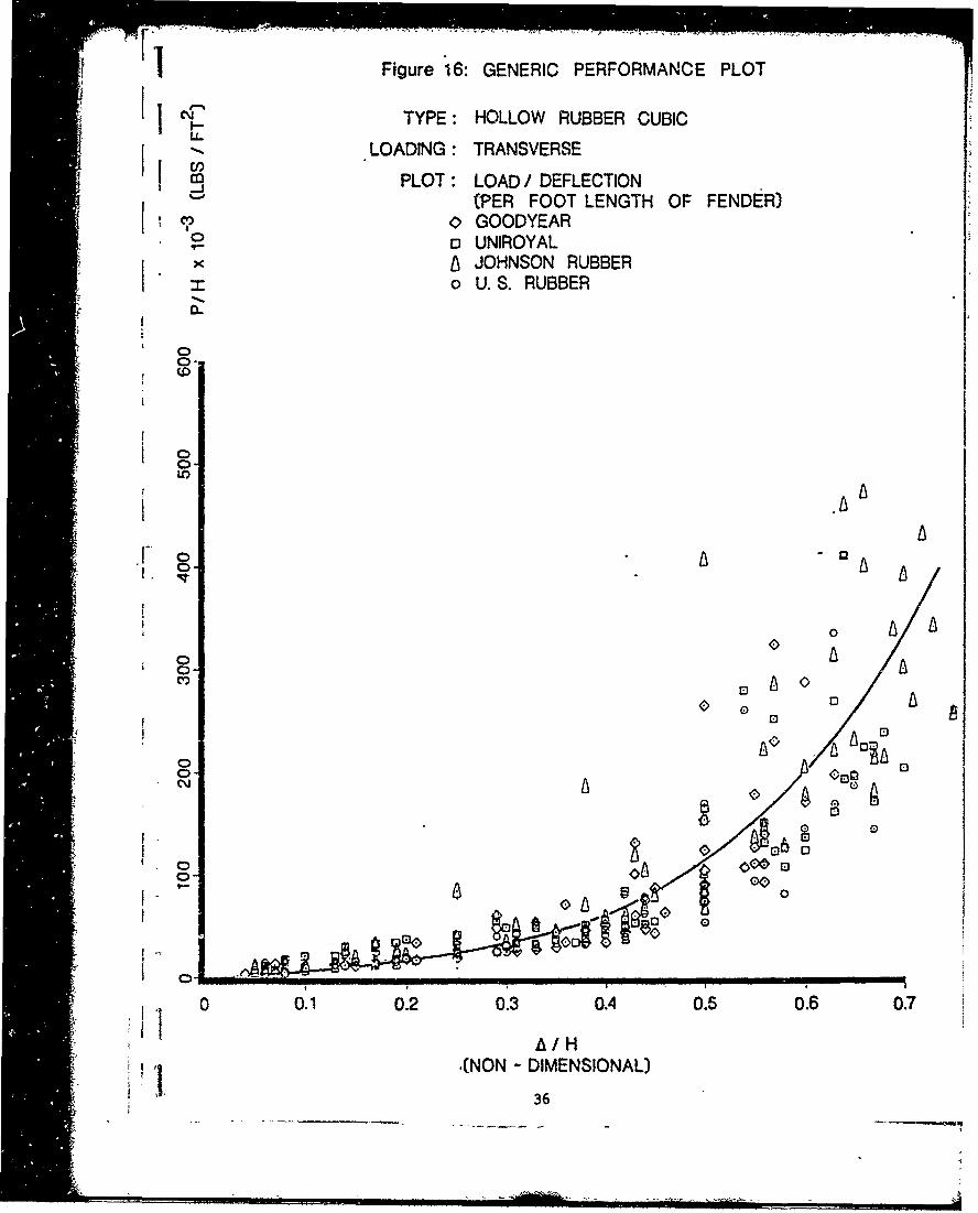
- - I'Figure 16: GENERIC PERFORMANCE PLOT
.•el TYPE: HOLLOW RUBBER CUBIC
*-LOADING : TRANSVERSECD PLOT: LOAD/DEFLECTION
(PER FOOT LENGTH OF FENDER)c?' GOODYEAR
- UNIROYALX× JOHNSON RUBBER
o U.S. RUBBER
0
0-0
10001
lo 0IA
I 08
o o
- - -- A A
0 03. 0
A HA
A A ..
i•'• ' I,], ,NON - DIMENSIONAL)
S36
"•'•"-•--'•o• .... 6- • . -,,.= , ",i -• '"l/" ""... - ".;•- ". c'"t w D- •

'1!1I
TRAPEZOIDAL RUBBER FENDERS -TRANSVERSELY LOADED
!37
FL.
* I

Ii Figure 17: TRAPEZOIDAL FENDER INSTALLATION
. .. ......
a lng oun~ew high Wing TyeTrapezoidal fenders. 10 ft.York, N.Y.
38

TRAPEZOIDAL RUBBER FENDERS - TRANSVERSELY LOADED
Trapezoidal rubber fenders employ two mechanisms in the absorption of
energy, these are: direct compression and buckling. They are generally
mounted directly to open-faced structures,or they can be used in combination
with timbering.
I Figure 18 indicates the generic load/deflection curve which is
characterized by the region of buckling generally occurring at approximately
30 percent deflection.
Figure 19 illustrates the generic energy/deflection curve for this type
fender. For this case the characteristic height of the fender in the direction
of loading was determined to be the significant condensing parameter for energy
absorption and load/deflection.
The following equations are representative of tradezoidal fender -
performance:
IE - HLWb {0.57X + 36.55X2 - 56.55X3 + 40.37X4 10 3 (10)
The corresponding load/deflection relationship is:
P - HL {105.82X - 207.06X2 48.24X3 + 423.72X4 103 (11)
where:
P - Reaction load (lb)
SWb - Fender base width (ft)
H = Fender height in direction of load (ft)
L - Fender length (ft)
E - Energy absorption (lb-ft)
K X - A/H (nondimensional, X < 0.53)
39
iI. . .....

- 2 F igure 18: GENERIC' PE RFORMANCE. PLOT ,
3111i30
29 TYPE: TRAPEZOIDAL RUBBERI1 CLOSED BASE
28 0"LOADING: TRANSVERSE .COMPRESSION
27 PLOT: LOAD / DEFLECTION26 (per foot length of fender)
25 O GOODYEAR
"24 0 UNIROYAL*23 A ISEIBU23
N% 210
~20
coo
19 0g -
13
12 0015 0
C 1 1
__-•" i• 13 9 0 r
00012 0
11 ~ 0 0
i||.0 O. 012
0.3 E).4
/E)l E)
44
- !Illl l
•nnp=111 I
0 iii1 0. 0. 0. . .~A/ 40---
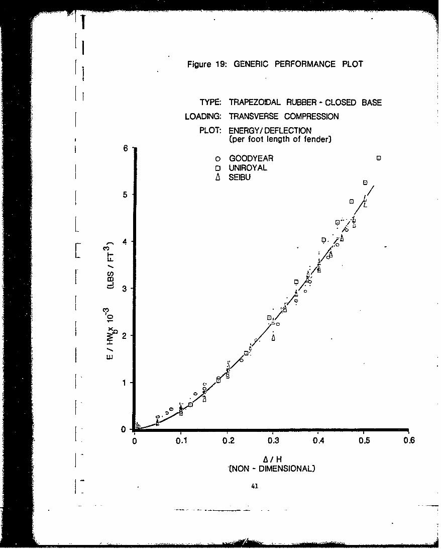
Figure 19: GENERIC PERFORMANCE PLOT1 II lII
TYPE: TRAPEZOIDAL RUBBER - CLOSED BASE
l LOADING: TRANSVERSE COMPRESSION
PLOT: ENERGY/ DEFLECTION(per foot length of fender)
I 6o GOODYEAR 0o UNIROYALA SEIBU
co
3-J
cv,
0
14
0,01l02 I31.40.l0.
(NON ,DIMENIONAL
il I41I

Jlii ii
SOLD YLNDICLJHER ENER
ii Ui•I
•1 el DIil
S... .____ I

liBII
I . . ..4.
.%...... .I an-. -
I!!!.
I m% .*IN
* .**H i
III.lI," r

4 • - -- -i• .• , - -• - --.-.. .. ... .
II
SOLID CYLINDRICAL SHEAR FENDERS
SI In shear fender installations, as in Figure 20, wooden fendering is fitted
over by means of supports on metal plates. The fenders are then mounted on
brackets secured to the quay. When the wood fendering is compressed, the shear
fenders are loaded into shear. Since the shear modulus of rubber is only a
third of its modulus of elasticity, reaction forces are kept low for this type
configuration.
Figure 21 indicates the generic energy absorption relationship which
-characterizes this type fender. In the figure fender energy absorption
curves have been condensed by the volume of the fender. The deflection
under load has been nondimensionalized by the fender height normal to the
loading.
The energy equation which characterizes this relationship is:
E = $H {O.54X + 8.79X2 1 103 (12)
The corresponding load/deflection relationship illustrated in Figure 22 is:
P 1 {22.77X + 1.14X - 1.43X3 ) 10 3 (13)
* iwhere:
P - Reaction load (lb)
X -A/H X < 1.0
D 0 Diameter of cylinder (f t)
, I 0 D t
I-H - Height of fender (ft)
A = Fender deflection under load
E - Energy absorption (ft-lb)
*• I 44

Figure 21: GENERIC PERFORMANCE PLOT
TYPE: 'SOLID RUBBER CYLINDER
LOADING: SHEAR
12 PLOT: ENERGY ABSORPTION
o VREDESTEIN"" ii o REGAL
100
8 00
06
00
2 0 0 )
00
00
I 3
IiiiiI I
02. 0. . 0. 0. 0. 07 08 09 10
1.01
• - _= = _= _
•! -=- -= 0• _" _- __ __- m--0
,tomB ][] 0
0iii l 802 03 04 05 0. . . . .Al IN (NNDMNINL
•lil I I I45

Ij Figure 22: GENERIC PERFORMANCE PLOT
(I iTYPE: SOLID RUBBER CYLINDERU LOADING: SHEAR
I 2 PLOT: LOAD / DEFLECTIONS"! 24
23 o VREDESTEIN cpoS22 '1' 22 EGL
21
020
19 0
"18
17-16 0 D
, " • 1 5 .i--LL 14
m 1312 0
C) 11
* ' 10
-9 /
8 0
7
6 00
5 .
J 43 0
21
0 0.1 0.2 0.3 0.4 0.5 0.6 0.7 0.8 0.9 1.0
AI/H(NON - DIMENSIONAL)
46

I{
ROTARY DONUT FENDERS -TRANSVERSE COMPRESSION
_ - _
iI-.e 47i'| i-

Figure 23: ROTARY DONUT FENDER INSTALLATION
* 48

. . . . . . ... ... .. •.' •,...i=. .
l4] 1 if
ROTARY DONUT FENDERS - TRANSVERSE COMPRESSION
Rotary fenders consist of hollow section rubber wheels which are mounted
on a control axis that allows them to rotate freely when ships horizontal shear
forces are applied. This type fender is available in multiple-wheeled configu-
rations in a variety of wheel size diameters. The hollow wheeled section
essentially absorbs its energy in material compression and exhibits signifi-,
cant absorption compared to the reaction loads developed.
S!!Figures 24 and 25 illustrate the energy absorption and reaction load
deflection curves derived for single-, double- and triple-wheeled fender
configurations. In these figures the energy absorption relationships have
been modified by characteristic dimensions of fender inner and outer diameters,
the number of donuts per axial and the width of the donut base. For the
reaction load relationship: the number of donuts, outer diameter and base
width were significant. For both relationships deflection was normalized by
the characteristic depth of the donut tire.
The generic relationships derived for energy absorption and load/deflection
and indicated in Figures 24 and 25 are:
• m e, 31X2 2 . 5 3 1 3E N$ {5.51X - 21.31X + 28-05X3 10 (14)
The corresponding load deflection curve determined was:
-- 322 63 18.64 13P NDWb {-0.45X + 67.32X - 189.6X + 188.46X 1 (15)
where:
N Number of donuts per axial
...... ,b(o-i)D I 9
]i ii•49
=-----------

I= D - Outer donut diameter (ft)0
. - Wb - Base width of donut (ft)
.D = Inner donut diameter (ft)
Ii E = Energy absorption (lb-ft)
P - Reaction load (ib)
X X < 0.68Do-Di[ 0 2.
II 2Fender deflection (ft)
* 5
i" 50
IT
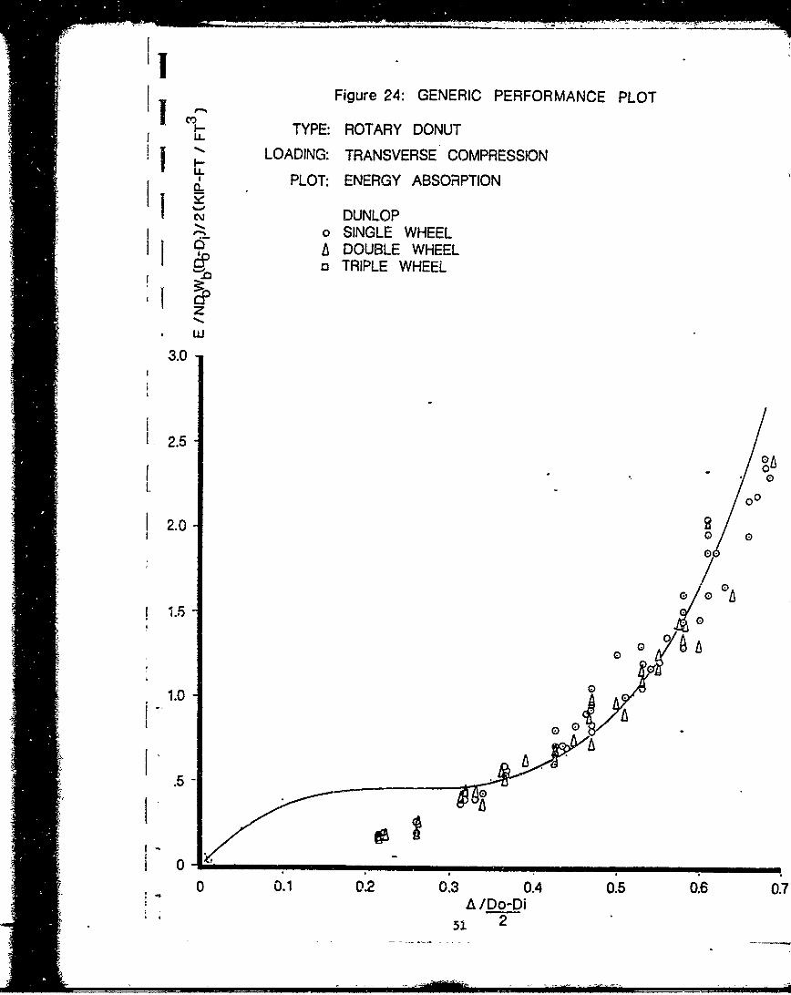
Figure 24: GENERIC PERFORMANCE PLOT
Li.!, TYPE: ROTARY DONUT
IjLOADING: TRANSVERSE" COMPRESSION. PLOT: ENERGY ABSORPTION
i DUNLOPI-A o SINGLE WHEELII.z . DOUBLE WHEEL
- TRIPLE WHEEL
3.0.
I 2.5
- O0
*00
2.000C
12.0 0
07
1.0
I'I'
.5-
0 0.1 02 0.3 0.4 0.5 0.6 0.7- A /Do-Di
51 2

-••• "•i) -'' .*'• .... .... .. . --
Figure 25: GENERIC PERFORMANCE PLOT
TYPE: ROTARY DONUT
LOADING: TRANSVERSE COMPRESSION
I% PLOT: LOAD / DEFLECTION
DUNLOP0 SINGLE WHEEL
DOUBLE WHEELTRIPLE WHEEL
13 ill b
12 -
11'* 10 -
vv8-
7
6/
4
3
2 S
0 .i i ! e "
0 0.1 0.2 0.3 0.4 0.5 0.6 0.7A Do-Di
52
:il52

PNEUMATIC RUBBER FENDERS FLOATING TYPE
53
- -i,•

Figure 26: PNEUMATIC FLOATING FENDER
I.. .......
1 54

, ____ ______ ______I__I__ __i__
PNEUMATIC RUBBER FENDERS -FLOATING TYPE
Floating pneumatic fenders utilize the compressive elasticity of air
to support loads. For this reason performance deterioration due to fatigue
1is absent. For realistic oblique ship loading, pneumatic type fenders do not
I suffer significant loss of energy absorbing capacity as do solid rubber fenders.
S* For rough weather mooring, this type fendering system exhibits much less damage
i -I due to the fact that maximum reaction forces under combined shear and compres-
- sion increase slowly and sustain large allowable deflections. Under excessive
loads these fenders do not result in excessive reaction loads as do solid or
bottomed out rubber fenders.
Figures 27 and 28 indicate the results for 32 different size pneumatic
fenders investigated. These fenders ranged in pressures from 4.3 to 11.4 psi
-l internally. Figure 27 illustrates the characteristic energy absorbing relation-
ship resulting from condensing the plot of energy absorption by the relationship
I1/1.4 2p LD . the pressure, length and diameter characteristic of the fender.
This quantity is plotted against the deflection normalized by the diameter of
the cylinder bag.
-- oThe following relationship was determined representative of energy absorp-
tion for pneumatic fenders.
E 8D {0.82X - 2.54X2 + 17.94X 3 10 (16)
The corresponding load/deflection relationship illustrated in Figure 28 is:
{iP - 5 .19X + 39.95X - 77.02X3 + 149.09X4 0 (17)
where:
- p /1 .4 LD
55

p - Internal pressure (psf)
L = Length of fender (ft)D 0 - Fender diameter (ft)
X =- A/Do, X < 0.55
A - Fender deflection (ft)
E - Energy absorption (lb-ft)
P = Reaction load (ib)
n56
iii 56

I Figure 27: GENERIC PERFORMANCE PLOT
TYPE: RUBBER PNEUMATIC - FLOATING BAG
LOADING: TRANSVERSE COMPRESSION
PLOT: ENERGY ABSORPTION
3.0 _ YOKOHAMA0 DUNLOP
2.5
i2.0
F 0z
z 1.50z
1.0
00
0 0.1 0.2 0 .3 0.4 0 .5 0.6
A~ /D (NON-DIMENSIONAL)57

S.Figure 28: GENERIC PERFORMANCE PLOT
TYPE: RUBBER PNEUMATIC-FLOATING TYPE
. .- LOADING: TRANSVERSE COMPRESSION 0'I PLOT: LOAD / DEFLECTION
0 DUNLOP0
'15II
15<
00co
__ ,limb
10z0
am mi
5
0 0.1 0.2 0.3 0.4 0.05 0.
A D (NON-DI0ENSiONAL)58

° II
I =i
RUBBER PNEUMATIC -AIR BLOCK FENDER
59

Ix
I'* Ii
* IjFigure 29: PNEUMATIC AIR BLOCK FENDER INSTALLATION
-9.-.
I . -
I . . .
I -,
60
I -*

S~1
1 RUBBER PNEUMATIC - AIR BLOCK FENDER
*, Ij Air block fenders are pneumatic, axially loaded fenders which can be
bolted to docks and applicable when floating bag types cannot be used.
They offer all the performance advantages that pneumatic bag types generally
exhibit.
The characteristic performance curves illustrated in Figures 30 and 31
were determined by nondimensionalizing the energy absorption and load/deflection
curves by P, H, and D, the characteristic pressure, height and diameter of the
block fender. The energy absorption and load/defelction relationships were then
"- plotted against nondimensional deflection A/H, the percentage fender height.
The resulting relationships are based on the investigations of 13 fender sizes
i at 14.2 psi. Since this type fender was available in only one pressure size,
S.1 the pressure variable was considered similar to the relationship determined
SI for floating bag types.
The following relationship is representative of the energy absorption of
air block fenders illustrated in Figure 30:
E SD {2.58X + 9.73X2 _ 13.40X3 + 40.09X4} 103 (18)
The corresponding load/deflection relationship illustrated in Figure 31 is
represented by:
* P - B {43.96X - 8.77X - 62.48X3 + 256.23X4 10 3 (19)
where:
E - Energy absorption
P - Reaction load
* 61* I
* I

S- p1 /1. 4 HD°
H - Fender height
D - Fender diameter
. .p - Internal pressure
X - A/H (nondimensional) X < 0.6
A - Fender deflection
The above relationships are valid for any set of consistent units.
Ii 62
iiiiBii

i ,'.-'-.
Figure 30: GENERIC PERFORMANCE PLOT
TYPE: RUBBER PNEUMATIC -AIR BLOCK.FENDERS
LOADING: AXIAL COMPRESSION
PLOT: ENERGY ABSORPTION
0 YOKOHAMA
5
4
.nJ
.4 1 Z0z
zIIm II
=--
0 0.1 0.2 0.3 0.4 0.5 0.6
A H (NON - DIMENSIONAL)
63
-• - -'

Figure 31: GENERIC PERFORMANCE PLOT
'1 TYPE: RUBBER PNEUMATIC - AIR BLOCK FENDERS
LOADING: 'AXIAL COMPRESSION
PLOT: LOAD / DEFLECTION
"o YOKOHAMA
m
6 0 .
50-
I'
@
.44Q 0
t •30.0z0
z
i20
30-
iz
100z.
, 0 0.1 0.2 0.3 0.4 0.5 0.6
A IAH (NON - DIMENSIONAL)64
,- .i i f . ii - ' l

LiiJNII
RUBBER PNEUMATIC -AIR BLOCK CUSHIONS
-65
"C *
iil65

"Fgue-2:AI BOC CSHO
; I,
* . I
* - .. . .. ... .2

IiI __ _ _ _ __ _ _ _
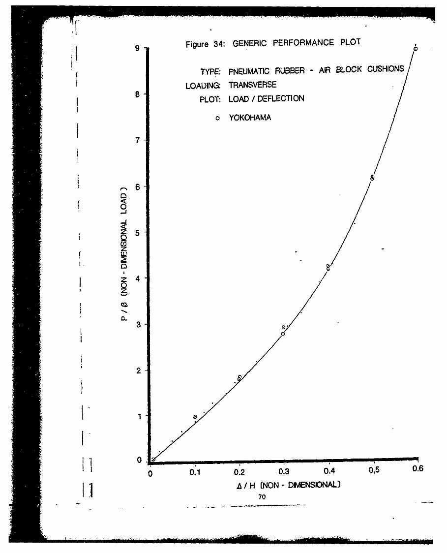
"RUBBER PNEUMATIC - AIR BLOCK CUSHIONS
This systeui is similar to the air block fenders except that it is
"rectangular in shape. It is mounted on a steel backing plate which can
be bolted to docks or semisubmersible drill rig legs. Although this fendering
system appeared to have a significant number of merits typically associated
with pneumatic systems, they were only available from one fendering manu-
facturer.
The data represented in Figures 33 and 34 are for only two fender
lengths at the same internal pressure. In these figures the energy and
load curves have been normalized by the characteristic pressure, length
and base width dimensions, while the deflection has been normalized by
the cushion height ii, the direction of loading.
[ The derived relationship which best fits the condensed data for energy
was determined to be:
E = BH -0.12X + 7.46X -_1271X 3+ 1477X (20)
The corresponding load deflection relationship is:
P -- 8---m2'X 1-X2 4O3 4 (3,P = B 19.22X - 4.16X + 5.10X + 29.55X (21)
where:
E = Energy absorption
P - Reaction load
B pl1/1.4 WLb
p Internal pressure
W b Base width of cushion
67
..- ... .----

L - Cushion length
H - Cushion height in direction of load
X = A/H, X < 0.6
-- A - Fender deflection
! The above relationships are valid for any set of consistent units.
68
i-1-

_- _ -
i, ,Figure 33: GENERIC PERFORMANCE PLOT
TYPE: PNEUMATIC RUBBER - AIR BLOCK CUSHIONS
. .,LOADING: TRANSVERSE
"2.0 PLOT: ENERGY ABSORPTION!1 II I
i . YOKOHAMA
1.75
1.50 -
~1.25z
z0 1.0zw5 .75
*~0. z-T-
j w .2 5
4 .50
S--I I *
0 0.1 0.2 0.3 0.4 0.5 0.6A /H
69
i - -- -* .--L -4 - l
S9 Figure 34: GENERIC PERFORMANCE PLOT
TYPE: PNEUMATIC RUBBER - AIR BLOCK CUSHIONS
LOADING: TRANSVERSE8 PLOT: LOAD / DEFLECTION
o YOKOHAMA
7
6
Z5CIOz
I4
0z
£ P
a.. 3 o
2
i01' 1
ii0 0.1 0.2 0.3 0.4 0.5 0.6
Iil A H (NON - DENSIONAL)70

I]
[.'" m•I FOAM-FILLED RUBBER FENDERS
Ill -
*ii~i.-
iii i. .N. N *-

I Figure 35: FOAM-FILLED- FENDER
F - j.*
~AN
72 -
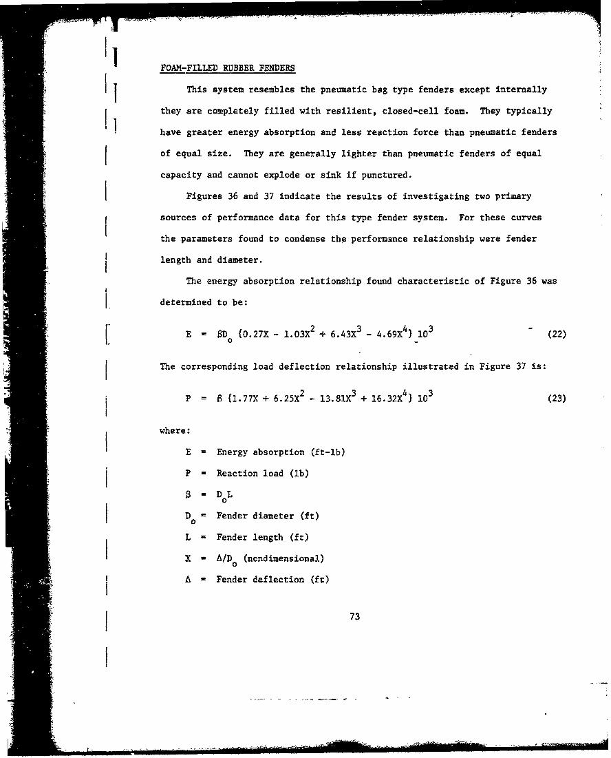
"FOAM-FILLED RUBBER FENDERS
This system resembles the pneumatic bag type fenders except internally
- they are completely filled with resilient, closed-cell foam. They typically
have greater energy absorption and less reaction force than pneumatic fenders
of equal size. They are generally lighter than pneumatic fenders of equal
capacity and cannot explode or sink if punctured.
•I Figures 36 and 37 indicate the results of investigating two primary
sources of performance data for this type fender system. For these curves
the parameters found to condense the performance relationship were fender
length and diameter.
The energy absorption relationship found characteristic of Figure 36 was
I. determined to be:
"E D {0.27X - 1.03X + 6.43X - 4.69X 4 10 (22)"L I
The corresponding load deflection relationship illustrated in Figure 37 is:3 4If 3
* i P = 6 {1.77X + 6.25X2 - 13.81X3 + 16.32X 4 103 (23)
where:
E= Energy absorption (ft-lb)
P - Reaction load (lb)
D = Fender diameter (ft)
L = Fender length (ft)
X -x A/D (nondimensional)
A - Fender deflection (ft)
I 73

"If Figure 36: GENERIC PERFORMANCE PLOT
0.8- TYPE: FOAM FILLED FENDER. LOADING: TRANSVERSE
PLOT: ENERGY ABSORPTION
0.7 L/ SAMSONii SEAWARD
0 .6.
cf)L-ý, .5
==/) 06-
_, 0..3-
i -0.4
0.202 . 0.' , .
A /D (NON-DIMENSIONAL)
74

I Figure '37:,.. GENERIC PERFORMANCE PLOT
13.5TYPE: FOAM FILLED RUBBER FENDERSLOADING: TRANSVERSE
PLOT: LOAD / DEFLECTION
0 SEAWARD13.0 6 SAMSON
2.5
I?0 m
1.0A
0A
0h0. 0.2 0'3 0.4 0,5_ 0.6 0.7
K ti /D (NON-DIMENSIONAL)75

SUMMARY TABLES FOR GENERIC FENDER ALGORITHMS
I 76

e S2
-J~~~~ z a &p 9
< x
I< e'jtf -'1 14 4 4 % i J i
ali ceocr - 0 V- LID
t I~ :C:
0 l 0CJ u0 ;~ I
C.) M- -' c
Zl C') 0 Lc) CJ UcQ Q )
Cl) C 0) co L() C 4
Q1 LO4J M
LUz W\ uN -) mm
W0) cm - o(5) U- 7. LW cj L nII co C? CF , N 0 .ci
C-j Y
0
00I~ ~ ~ ~ C co vnwinmnimn lmimCm7

.S2
> X
LO L
z ~
Cw Lo~% C~ OLU CY % Lo C ~
~ 10 U)
<o o 04 U-) CV)
~j z IT V-. V- CM -
C,, UY) () CIDa) ') CC) ED r CD CM). 0) 7D U')
oo 0 CD -Ja: ZC CD. 0)
0 < v: C ~ C U vQ ~ C . I.)--0 Q 'oC rC) - 6 6C
F- I - a x
C/ (. m, +~ 0 CC) L-
M: LL M*) 0* Xr CI r-
C~ L6) Cf C
LUC~ P.0 I - 9
00 C. M- Veco -cc0,a, a<L or~C OCY X -xci
a. N~i up. m-
-J -o coi mu C13
co O3CYzx clU-
00+ I :;uCX YLmr mCC t x a ujU mm 4LZy n ~

V. RANKING OF FENDER SYSTEM MECHANISMS
Commonly available fenders from manufacturers of fender systems operate
on the basis of one or more mechanisms which determine the way An which thefender stores energy and deflects under loading. These mechanisms are commonly:
a. Axial compression
b. Transverse compression
c. Transverse shear
d. Pneumatic bag compression
e. Foam-filled bag compression
These different mechanisms result in considerable differences in the basic
performance characteristics of the individual fender types. The ranking of
energy-absorbing mechanisms takes on a significantly different importance
depending on the measure of merit or goal which is established for the ranking
process. Since a designer is concerned with many variables such as fender
energy absorption, reaction load, deflection, relative system costs, system
durability, etc., the ranking of fender mechanisms will vary in accordance
with his selected criteria. For purposes of this discussion, only two measures
of merit are considered: energy absorption capability and reaction load as a
function of deflection. These measures of merit are generally diametrically
opposed.From a design point of view, one would like maximum energy absorption
with minimum reaction load generation for a given deflection. In ranking the
candidate mechanisms, the first approach considers which mechanisms absorbed
the most energy for a given deflection with reaction load not a factor. The
second viewpoint considers which mechanisms resulted in the least reaction
load for a given deflection not considering energy absorption.
79
k -

II VI I. PRELIMINARY FORMULATION OF THE FENDER/VESSELINTERACTION RESPONSE PROBLEM
The references included in Appendix A relative to the ship/fender
response problem have been designated by (**). These references approach
the dynamic response problem in various ways and to various depths. Of the
references cited in Appendix A, the "Dynamic Response of the Ship and the
Berthing Fender System after Impact," (37) included as Appendix B for
ready reference, was considered the most appropriate for further development.
The response problem formulation appears generalized enough to be
adapted to include the generic fender algorithms preliminarily developed
in Phase I work and hull, dock and berthing characterizations.
The essential task steps envisioned for Phase II efforts would include:
* Formulate the generalized equations of motion for the vessel/fenderdynamic interaction problem based on the approach identified inPhase I work. This approach will consider fender performancealgorithms, local vessel stiffness, dock mass and stiffness, vesseland berthing characteristics.
* Characterize vessel local hull or appendage stiffness.
• Characterize dock stiffness and mass characteristics.
* Characterize hydrodynamic mass and damping for vessels considered.
* Computer code methodology.
* Validate results against existing experimental data.
• Validate results against proposed test program.
It is envisioned that the first two task elements above would be based on
Phase I results, references (37, (32) and (33), the basic methodology for
the dynamic problem and studies related to local hull stiffnesses. Task 3
will be approached through a representative dock characterization for the
80
C--- .Ci

II
ship selected initially as part of the response problem. The hydrodynamic
mass and damping characteristics for this vessel would be investigated using
references (37), (20) and (75) in addition to other relevant sources of mass
n and damping information.
1 It is assumed that computer coding of the dynamic equations of motion
and their bolution will require the significant Phase II effort. An initial
validation effort will include correlation between program results and any
known test results for which comparisons can be made. These will consider
the results in references (8), (62), (21), (26) and (3) but not be limited
to those references.
Actual test programs to be developed as part of task 7 would consider
validation of fender algorithms for large size generic fenders via static
_I or model testing since most data issued by manufacturers is based on extrapolation
I j of small scale test data. This would be further developed as part of Phase II
efforts. In addition, test programs could include validation of response
I program results through small scale model testing. This also would be
developed further into Phase II efforts.
I8
18
..........................................- t4

Silia
Im•,I
: I
Appendix A
BIBLIOGRAPHY
1A-1

Bibliography
1. Ackroyd, J., "Why Fender? What Fender?" International Dredging & PortS Construction, January 1981. This article examines reasons why port authoritiesand shipowners fit their structures and vessels with expensive fendering systems,at a time when costs are rising rapidly and every kind of economy is beingexercised.
2. Atack, D.C., Kohring, W., "Berthing and Mooring Systems for Mammoth Ships." Dockand Harbor Authority, October 1970.
*3. Balfour, J.S., Feben, J.C., et al, "Fendering Requirements/Design Fender Impact
y Criteria." Ports '80, 1980. The paper describes the collection and analysis of3 berthing impact energy records from the BP jetties in the 6th Petroleum Harbor,
Rotterdam. It shows that a simple logarithmic transformation of these recordsyields a distribution that can be extrapolated to predict extreme probabilityvalues. Records for several groups of fully and part laden oil tankers areanalyzed.
*4. Beach, R.L., Davis, N.B., "Specialized Fender Sys:ems Requirements and Design."SPorts '80, ASCE, May 1980. Case studies are presented for the berthing of large
vessels with low allowable reaction pressure loads. The case studies includei specific design cases where large floating foam-filled or pneumatic fenders and
floating donut fenders have been utilized. Fender selection, spacing, riggingand operational experience are detailed. These cases are not meant to summarizeall types of standard dock fendering designs, but'to instead provide an analysisof several unique and specialized designs.
5. Bijlsma, T.J., "Super Fenders for Super Tankers." Dock and Harbor Authority,April 1970.
**6. Blok, J.J., Dekker, J.N., "On Hydrodynamic Aspects of Ship Collision with Rigid orSNon-Rigid Structures." Offshore Technology Conference 3664, April 1979. ?*,eltest data to support the design of fendering systems is presented.
k7. Broersma, G., ?dddelbiik, C.G., "Middlebiik Fender." Naval Engineers Journal,April 1971.
*8. Brolsma, J.U., Hirs, J.A. et al, "Qn Fender Design and Berthing Velocities."
1 .4th International Navigation Congress, 1977. Two aspects of fender design areemphasized in this paper, calculation of energy to be absorbed by the fender, andberthing velocities. Measurements of berthing velocities at Europoort, Rotterdam
II are included.
9. Brolsma, J.U., "Docking and M~oring of a VLCC Inside a Harbor." Symposium onj Shiphandling, Netherlands Ship Mbdel Basin, 1973. The paper discusses two
electronic navigation devices designed to assist in the berthing of VLCC's, theshore-based jetty approach speed system and the ship-based Sonar Dopplar System.
II.0. Brunn, P., "Alternative to Conventional Fendering." Norwegian Institute ofTechnology, April 1979. The paper examine4i.zhe concepts of forced fendering andrecoiling versus non-recoiling fenders. Arguments for and against forced
A-2

I fendering systems are presented. The Irving marine (non-recoiling) fender ishighlighted.
il i Brunn, P., Wharves and Ouays." (Chapter from the Book - Port Engineering.) GulfPublishing Company, 1976. This book is a basic research tool for the designer ofports and port structures. Chapter subheadings include: Berthing and Mboring"Forces on Structures; Fenders; and Dolphins. The book contains excellentdiagrams of various port structures.
12 Carlin, B., Ibrley, C, et al, "Offshore Fender Systems." Det Norske Veritas,1 November 1977. The stated objective of this study was to give recommendations
for the protection of offshore structures, covering both design criteria andpossible fendering systems. The scope of the work covers shipping in the North
j Sea in general and shipping in the vicinity of offshore installations inparticular. An evaluation of relevant design criteria included looking intocollision mechanism and establishing force deflection and energy deflection curvesfor ships and platfcrms. A literature survey of fendering systems was alsoperformed.
3. Chapman, P.O., "Comparative Tests of Boat Fenders." 1961, USCG, Baltimore,Maryland.
4. Davies, I.L., "A Method for the Determination of the Reaction Forces andStructural Damage Arising in Ship Collisions." EUR 237 European OffshorePetroleum Conference and Exhibition, October 1980.
1'5. Dent, G.E., Saurin, B.F., "Tanker Terminals, Berthing Structures." Conference onTanker and Bulk Carrier Terminals, Institute of Civil Engineers, November 13,1969.
16. Dent, G.E., "Berthing Structures for Large Oil Tankers." Structural Engineer,February 1964.
17. de Oliveira, J.G., "Simple Methods of Estimating the Energy Absorption Capabilityof Steel Tubular Members Used in Offshore Structures." University of Trondheim,I Norwegian Institute of TecLnology, August 1979.
"*18. Derucher, K.N., Heins, C.P., "State of the Art Bridge Protective Systems andI Devices." Uniersity of Maryland/USCG, 1979. This 320 page report is intendedas an aid in the design of bridge protective systems and devices. The reportincludes; (1) factors considered in design and type of systems used; (2)advantages and disadvantages of seven types of fendering systems; (3) material
I properties of fendering systems; (4) design parametsr; (5) hand calculation andcomputer application; and (6) conclusions and recommendations of state of the artstudy.
I'. Drelicharz, J.A., "Design, Construction atid Installation of the Rich Ship'sFendering System at Naval Installations." CEL, February 1971.
*I. Endo, H., "Motions of a Vessel M'ored Near Vertical Walls and With Limited Under-Keel Clearance." University of Hawaii, Hay 1981. The purpose of this study isI to develop a method for computing the hydrodynamic characteristics of and the wave
A-3-
i fI.ill l~ii ~ lini ...

i ! excitation on a three-dimensional vessel of arbitrary shape floating freely inshallow water and near two semi-infinite vertical walls placed at right angle toeach other.
*,1. Fontijn, H.L., "Berthing of a Ship to a Jetty." Journal of Waterway Port Coastalzind Ocean Division, May 1980. This paper presents a mathematical modeldescribing the behavior of a ship berthing to a Jetty (or similar facility) andpredicting the fender loads in a theoretical way, in which all essential featuresare maintained and that produces quantitative results of sufficient accuracy for
practical applications. To this end, use is made of the so-called "impulseresponse function (IRF)" technique, which has as the restriction that the ship-fluid system is supposed to be linear and time invarient.
12. Fontijn, H.L., "The Berthing Ship Problem: Forces on Berthing Structures from1boring Ships." Delft University of Technology, 1978.
3. Ford, D.B., Young, B.O., Waler, G.W., "Hi-Dro Cushion Camel - A New FloatingFender Concept." Conference on Coastal Engineering, London, September 1968.
S. Fumes, 0., Amdahl, J., "Computer Simulation Study of Offshore Collisions andAnalysis of Ship-Platform Impacts." Brazil Offshore 1979. The paper outlinesa method to evaluate the probability of collisions between ships and fixedoffshore installations by making use o! simulation techniques. The greaterbenefit of the method is to compare various alternatives by assessing the relativefrequencies of collision. A total risk assessment was not feasible for the timebeing due to the scarcity of data concerning collision events. In brder to
I j account for the influence of both human failures as well as actions taken to avoidcollisions, the model was being linked to an interactive. simulation unitdeveloped presently by DnV.
I.s... Girgrah, M., "Practical Aspects of Dock Fender Design." 24th International
Navigation Congress, 1977. The author reviews briefly the first stage of dockfender design relating to energy computation, and discusses, in some detail,practical aspects of fender system design.
j•. Goulston, G., "Ikasured Berthing Energies and Use of Control Instrumentation."NATO Conference on Berthing and ?boring of Ships, 1973.
"Han, E., Priori, G., et al, "Improved Fender Systems for Shallow and Deep DraftBerths, Phase I." Dravo Van Houten/Marad, June 1976. This report was writtenwith port administrators and operators in mind. The purpose of the study was toexamine the nany types of fender damage and interrelated causes oi damage and thento rank the problems in terms of relative importance. The ultimate objective ofthe Phase I report was to develop apecific design objectives which are to be usedas the basis for specifications and type plans for possible solutions as part of
* - the future Phase IT study.
*218. Heins, C.P., Derucher, K.N., "Force Interaction of Piers, Wharves and Fenders."
* Journal of Civil Engineering Design, 1979. The paper discusses the problem ofI ship impact forces against interactive pilings. A series of design charts havebeen prepared, relating the interaction of a series of vertical pilings andassociated horizontal whalers and their respective stiffnesses.
A-4
P-. .¾ * ~. .

I
f*29. HJelde, E., Nottveit, A., et al, "Impacts and Collisions offshore. ProgressReport No. 2: Pilot Tests with Pendulum Impacts on Fendered/Unfendered ConcreteCylinders." Det Norske Veritas, February 1978. The report describes a pilotstudy to the main experimental investigations described as Part Project No. 5 inthe main project "Impacts and Collisions Offshore." Two concrete cylindricalshells have been tested with a local radial impact load with and withoutfendering, in order to obtain early information about dynamic responses and therelationship between input energy and impact loads. Prior to the impact tests,the models had been used in another project, where they were tested to failureunder hydrostatic pressure. Thus, the "models" described in this report shouldonly be understood as "foundations" or suitable impact-receiving bodies for theimpact tests.
30. Holley, M.J., "Fendering for Structural Steel Dolphins." Hansen Holley andBiggs, Cambridge, Mass. 1976.
31. Hysing, T., "Impacts and Collisions Offshore. Progress Report No. 4, Analysis ofPenetration of Hull." Dot Norske Veritas, July 1978. A theoretical calculationmodel has been developed to determine the relationship between load and
penetration and the corresponding energy involved during indentation of the sideof a ship. The model is based on large plastic deformations and takes intoaccount the membrane tension stresses in the ship's side, deck and bottom and theplastic buckling load of the deck, bottom and transverse frames.
32. Kawakami, M., Nobukawa, H., et al, "On the Required Function of Fender Consideringof Prevention of Damage of Ship Side Structure." ftiroshima University, 1976.
33. Kawakami, M., Nobukawa, H., et al, "On the Relations of Fende- to Strength of ShipSide Structure." Hiroshima University, 1975.
34. Khanna, J., Bict, C., "Soft Mooring Systems at Exposed Terminals." ASCE Port 77Specialty Conference, Long Beach, California.
35. Kikutani, H., "Some Requirements for the Design of Sea-Berths from the View-Pointof Ship Handling." 24th International Navigation Ccngress, 1977. As indicatedin the title, the paper analyzes the problems associated with designing sea-berthsfrom the view-point of tanker maneuvering and handling. After surveying shipcaptains and berth owners on the subject of tanker berthing, the authors presentsome sea-berth design requirements.
.36. Ko'an, B., "Fender System Requirements at Open-Sea Berths." Ports '80, ASCE, May,1980. This paper discusses the special fender design requirements necessitatedby the oscillations of moored ships at offshore terminals. E:amples of energyabsorption and load deflection curves are given for breasting dolphins.
7. Komatsu, S., Salman, A.H., "Dynamic Response of the Ship and the Berthing FenderSystem After Impact." Japan Society of Civil Engineers, Proceedings, 1972.This paper describes a method of analysis for evaluating the portion of shipkinetic energy and impact force transmitted to a berthing structure provided withfenders which have linear or nonlinear spring constant. In the analysis thedynamic responses of the ship, fender and berthing structure, after impact, areconsidered, and derived equations for the selection of different parameters needed
S~A-5

Ji | for the solutions of the dynamic equations are included. These are comprised ofthe virtual mass of the ship, in both translational and rotational motion, in
addition to the time interval required for the solutions of the motion equationsby numerical integration methods.
**38. Komatsu, S., Salman, A.B., "Generalized ýthod for Designing Petractable FenderSystems." Japan Society of Civil Engineers, April 1971, This paper describes ageneralized method for designing the retractable fenders system. The presentedtI hypothetical method of design is based on the mathematical analysis of thefrictional resistance created during retraction, between the fender frame and boththe ship hull and the sliding surface of the supporting brackets. In the designprocedure included herein, a particular attention is directed to the influence of
SI I the combined dynamic behavior of the system, including the berthing ship, thefender and the marine structure.
39. Lackner, E., Wirsbitzki, B., "Fendering for Bulk Carrier Ports and ContainerTerminals." 6th International Harbor Congress, May 12-18, 1974.
40. 1Larsen, C.M., Engseth, A., "Ship Collision and Fendering of Offshore ConcreteStructures." European Offshore Petroleum Conference and Exhibition, October1978. The first part of this paper discusses the risk of collision betweenoffshore platforms and ships, and how that risk might be taken into considerationwhen designing a platform. Part 2 describes a fender proposal for protecting adeep water concrete platform.
41. Laura, P.A.A., Nava, L.C., "Economic Device for Protecting Bridge Piers AgainstShip Collisions." Ocean Engineering, 1981. This brief technical note describesa floating energy-absorbing device designed to protect bridge piers. It consistsof a floating V-shaped system of concrete barges.
•*42. Lean, G.H., "Subharmonic ?btions of Moored Ships Subjected to Wave Action."
t43. Lee, T.T., "Biological and Physical Deterioration of Timber Fender Systems."University of Hawaii, June 1981. Biological deterioration and mechanical damageby berthing and mooring ships have significant effects on energy-absorptioncapabilities of conventional timber fender piles. This paper presentssignificant findings of on-site investigations and subsequent technical andeconomical analyses of existing fender systems at ten representative Navalstations and shipyards on both west and east costs. Special emphasis is placed on
* .the effects of biological and physical deterioration on the cost effectiveness ofapproximately 200,000 linear feet of fender systems studied.
-44. Lee, T.T., "Hydraulic-Pneumatic Floating Fender - Additional In-Service Tests,Second Series." CEL, March 1967. This report summarizes the results of in-"service tests of two experimental hydraulic-pneumatic floating fenders in the
] harbor of San Diego, California. The test period was from June 1965 to June1966. A previous series of tests, reported by Lee (1965a and 1966a), covered a19-month period - 14 months in a well-protected harbor (Port Hueneme, California)and then 5 months in a moderately exposed harbor (San Diego). Full-scale
.. measurements of 35 berthing impacts at Port Hueneme were also reported. It wasconcluded that the energy-absorption capacity of the fender is adequate for awell-protected harbor and that the fenders provided satisfactory service during
"A-6

the preliminary tests at San Diego. Rowever, the following shortcomings werelisted and have existed since the initial tests: (1) high initial and maintenancecosts, (2) excessive distance (up to 5 feet) between moored ship and wharf faceJ due to the width of fender, and (3) high rebound forces resulting from the use ofpneumatic rubber bags on the test fenders.
11*45. Lee, T.T., "Hydraulic-Pneumiatic Floating Fender - Additional In-Service Tests,First Series." CEL, March 1966. Tests of two experimental hydraulic-pneumaticfloating fenders, first in a well-protected harbor (Port Hueneme) and then in arelatively exposed harbor (San Diego), are described. Each fender consists of a50-foot long bulkhead fronted by two air-filled and two water-filled rubberbags. Also included is information to aid engineers in increasing the energy-absorption capacity of existing dock fender systems.
*46. Lee, T.T., "Review of 'Report on the Effective Fender Systems in EuropeanCountries', by Risseleda and Van Lookern Campagne." CEL, October 1965. Withthe purpose of providing improved fenders for U.S. Navy used in berthing ships upto 20,000 tons, a Navy-contracted report by Risselada and Van Lookeren Calmpagne ofthe Netherlands on effective fender systems in European countries is digested andreviewed. Additional material has been added by the reviewer to provide a moreuseful treatment of the subject of European fendering systems. This report isintended as a supplement to NCEL Technical Report R-312, "A Study of EffectiveFender Systems for Navy Piers and Wharves," issued March 1965. SignificantEuropean systems are described, with emphasis on systems attached to docks.
47. Lee, T.T., "Imarine Fender." Department of the Naly, Patent Appl. April f965.
*48. Lee, T.T., "A Study of Effective Fender Systems for Navy Piers and Wharves."
Naval Civil Engineering Laboratory, Technical Report R-312, March 1965. Thereport is intended to assist engineers in the selection of effective andeconomical fenders. Search of literature, consultation with authorities, fieldinspection and research, lead to the conclusions that, for berthing ships of up to20,000 tons displacement, the most effective and economical fender systems forNavy docks are: (1) for sheltered harbors, a modified retractable system; (2) forunsheltered harbors, standard greenheart timber pile with rubber bearing block atdeck level; and (3) for dock corners generally, the Raykin (rubber-in-shaer)system. Drawings and specifications for the three recommended fendering systemsare included. Also included are: (1) comments by authorities in the field ofmarine fendering, (2) case histories, (3) load transmission and energy-absorptiondata, and (4) cost of construction and maintenance.
*49. Lee, T.T., "A Hydraulic-Penumatic Floating Fender." Naval Civil EngineeringLaboratory, Technical Report R-334, February 1965. The report is intended toprovide technical information and data to engineers and designers who are
* concerned with an effective increase in the energy-absorption capacity of existingfender systems. In-service tests of two 50-foot long floating fenders (each abulkhead fronted by two water-filled and two air-filled bags) indicate that they
* meet the requirements of reducing damage to piers, ship-hulls and pier. fenders,particularly in protected harbors with only moderate swell and wind.
*50* Lee, T.T., "Evaluation of a Hydro-Pneumatic Floating Fender or Camel." Naval
i == _-'L• I
i ii [Civilh pElngineerin Laboratoy TeanDical. Note Ner, June 1963.n Thshworkcoins part
i II 'Ilsted andhave exised sincethe inita-?et:()hihiiilan aneac
,•mn

S~I!
'I .of an effort to develop a family of camels (floating fenders) which will be lower''• in combined first cost and maintenance costs than existing fenders and will reducedamage to ship-hulls or to pier fender systems. The performance in Port Hueneme(California) Harbor of a pair of 50-foot long hydro-pneumatic camels has beenstudied over a four-month period.
151. Lee, T.T., "Design Criteria Recommended for Marine Fender Systems." Naval CivilEngineering Laboratory. This paper summarizes the world-wide effectiveness ofmarine-fender systems. A design criteria is recommended as a result of anextensive research and development program executed at the U.S. Naval CivilI Engineering Laboratory, Port Hueneme, California, under the sponsorship of NavalFacilities Engineering Command. Pertinent information includes analyticaltreatment and experimental investigation of the effects of berthing impact on thedesign of berthing structures; definition, function, and types of fendersystems; advantage and disadvantages of various fender systems, cost-effectiveness and design procedures for different marine environment and exposureconditions. The energy absorption characteristics, berthing velocity, andvirtual mass of ship are discussed in detail.
'2. Li, S-T, Ramakrishnan, V., "Ultimate Energy Design of Prestressed Concrete FenderPiling." ASCE, Journal of Waterways, Harbors and Coastal Engineering Division,November 1971. This article examines the advantages of lightweight, prestressedconcrete fender piling over other types of marine fender materials. Energyabsorbing capacity, ultimate energy design and optimum stress are among thefactors analyzed.
1 3. March, F.A., Davis, N.B., "Floating Donut Fendering System." CoastalEngineering, 1979. A new dock fendering system with special application in
Im_ remote areas and areas of large water level variation is described. The systemis based on the use of a large floating Donut fender which rides up and down on acentral driven steel piling. A summary of general design requirements for dockfendering systems is presented, followed by a description of Donut fenderconstruction and features.
**54. Oortmerssen, G., "Berthing of a Large Tanker to a Jetty." Offshore TechnologyConference, May 1974. A method to describe the berthing maneuver of a largetanker to a jetty is presented. The method, which results in the perdiction ofmaximum deflection of and maximum load in a dolphin, is based on an equation ofmotion with a constant added mass coefficient and zero damping. Data are
* presented on the added mass and damping of large tankers in shallow water.
55. Ostenfeld, C. et al, "Ship Collisions Against Bridge Piers." Offshore TechnologyConference Proceedings 1975, 2252.
56. Petersen, M.J., Pedersen, P.T., "Collisions Between Ships and OffshorePlatforms." Offshore Technology Conference, May 1981.
57. Fiaseckyj, P.J., "State of the Art of Fender Design." 24th InternationalNavigation Congress, 1977. The author is a technical consultant to Mitsubishi
* International Corporation for "Seibu" Dock Fender in North America. In this paperhe reviews three systems, the ship (docking operation), the fender (design andspacing), and the berthing structure.
A-4
C -

58. Powell, R.G., Carle, R.B., "The Use of Hydraulic Cushioning in the Docking ofSuper Tankers." Offshore Technology Conference, May 1972.
1*59. Ouinn, A., "Design and Construction of Ports and Marine Structures." McGraw-Hill, 1976. An extremely valuable source of fendering performance data. Thechapter includes numerous tables with load-deflection, energy absorption and
iI reaction data, and diagrams depicting specific brand-name fenders.
60. Reese, L.C., O'Neill, M.W., et al, "Rational Design Concept for BreastingDolphins." ASCE Journal of Waterways and Harbor Division, May 1970. A singlefreestanding tubular pile-dolphin forms the basis of the design concept examinedin this article. The authors present an informative discussion of breastingabsorption capabilities, and include a case study as an example problem toillustrate their design concepts.
**61. Seidl, L.H., "A System for the Analysis of the Dynamics of Vessels and PlatformsMoored Offshore." Brazil Offshore 1981 International Symposium, September1981. A systematic approach for the numerical simulation, of the behavior of
* vessels or platforms moored offshore is presented. The paper illustrates how"different analytical techniques are used in various applications. Among theapplications discussed are those of vessels moored to conventional pier-typeoffshore loading terminals, vessels or platforms moored to offshore multi-pointmoorings and finally single point moorings. The theoretical background for eachof the analyses is presented first. The method of treating the various componentsof the mooring system as well as the -assessment of the nonlinear, mooringrestoration function for the time-domain analyses Is then outlined.
.*62. Seidl, L.H., Lee, T.T., "Correlation between Theoretical and Experimental Valuesof ?btions and Mýoring Forces of Ships Mbored at a Sea Berth." 3rd InternationalOcean Development Conference, Tokyo, 1975.
63. Surin, B.F. "Berthing Forces of Large Tarkers." 6th World Petroleum Congress1963, Frankfurt, Section VII, Paper 10.
64. Svendsen, I.A., "Measurement of Impact Energies on Fenders." Dock and HarborAuthority, September 1970.
65. Svendsen, !.A., Jensen, J.V., "Form and Dimensions of Fender Front Structures."Dock and Harbor Authority, June 1970. This article discusses the requireddimensions the front structure of a fender must have to avoid the fender causingplastic deformations in the side of a ship. Diagrams for tankers and bulkcarriers are presented from which the dimensions of the fender front can bedetermined when the fender force and the size of the ship is known.
**66. Takagi, M., Shimomura, Y., et al, "Design of Mooring System of Vessels InsideBreakwater." Ocean Engineering, 1981. A method of simulation calculation for amooring system of vessels inside a breakwater is illustrated. Using a simulationprogram based on the above method, a test design for a mooring system for oil-storage vessels of total 5.6 million kiloliters rzas conducted. In order to obtaindata for the simulation program, various experiments such as wind tunnel tests totest wind resistance, and wave tank tests to test the waves transmitted through orover the breakwater, and the motions of vessels inside the breakwater due to
A-9
I|

waves, were conducted. Some proposals concerning design criteria and safety* factors are presented. Finally, the results of the test design under estimated
sea and weather conditions are shown, and the design is concluded to be bothtechnically and economically feasible.
67. Tam, W.A., "Dynamic lboring and Fendering System." Offshore Technology ConferenceSII 1971, April 1971.
68. Terrell, M., "A New Look at Fendering Systems." Dock and Harbor Authority, .y
1972.
69. Thoresen, C.A., Torset, O.P., "Fenders for Offshore Structures." 24thInternational Navigation Congress, 1977. The design of fender systems for fixedoffshore structures and the influence of collision potential between ship andstructure.
"70. Thorn, B.J., "Engineering and Economic Evaluation of Floating Fender Concepts."CEL, June 1966. This report contains an engineering and economical evaluation of
* eight different concepts of floating fenders to be con- idered for Navy docks.The engineering aspects involve discussion of different design criteria, such asvessel approach velocities, acceptable lateral dock loads, hull loads and stressesin structural timber. A description of the dynamics of a berthing ship is given,including a discussion of the various energy correction coefficients to beused. The hydrodynamic mass coefficient is especially emphasized. The resultsobtained on this coefficient by many different investigators are summarized,showing that large unexplained discrepancies exist.
'1. Toppler, J.F., Harris, H.R.. Weiersma, J., "Planning and Design of Fixed BerthStructures for 300,000 to 500,000 DWT Tankers." Offshore Technology Conference,May 1972.
**72. Van Orrschot, J.H., "Subharmonic Components in Hawser and Fender Forces."
Coastal Engineering, 1976. Forces in mooring lines and fenders of a mooredvessel exposed to waves have a mixed harmonic and a subbarmonic character. Thnesubharmonic oscillations, with periods well beyond the range of wave periods, maycause forces that are as large as, or even larger than the forces associated withthe harmonic oscillations. The origins of the subharmonic oscillations arediscussed and it is shown that in model testing, the correct reproduction of boththe mooring arrangement and the irregular wave motion is essential.
3. Vasco Costa, F., "Dynamics oi Berthing Impacts." NATO Advanced Study Instituteon Analytical Treatment of Problems in the Berthing and Mboring of Ships, Nay1973. The analytic approach presented in this paper is intended to help navalarchitects with the design of ship's hulls, engineers with the selection offenders and the evaluation of the forces on which to base the design of berthingstructures, and, finally, to help masters and pilot choose berthing proceduresless likely to go wrong.
74. Vasco Costa, F., "Fenders as Energy Dissipators." Dock & Harbor Authority,September 1979. The author's purpose in writing the article was to point out theadvantages of developing new types of fender systems that dissipate energy insteadof giving it back to the ship.
A-10

1^5. Vasco Costa, F., "Mechanics of Impact and Evaluation of the Hydrodynamic Mass,Analytic Study of the Problem of Berthing." July 1965.
]6. Vasco Costa, F., "Shipping Ropes as Energy Absorbers." Dock & Harbor Authority,- October 1978 and February 1979.
f 7 . Vasco Costa F., "The Berthing Ship, the Effect of Impact on the Design of FendersI and Other Structures." The Dock & Harbor Authority, May, June and July, 1964.
8. Vine, A.C., "Advanced Marine Technology. Handling and Transfer at SeaSection." Woods Hole Oceanographic Institute, ONR, December 1974.
"79. Young, R.A., "Marine Fender Specifications." Ports '80, ASCE, May 1980. Thispaper examines the various parameters and characteristics which can be specifiedfor a marine fender system. These factors include vessel size range and type,type of installation, fender size and arrangement, energy, reaction, deflection,hull pressure, elastomeric material, etc.
'80. "Cambridge Fender." Tanker and Bulk Carrier, March 1969. A brief descriptionof the Cambridge fender including its energy absorption capabilities.
*81. "Dunlop Oil and Marine Division Fender Manual." Dunlop Oil and Marine
Division. This very complete manual describes in detail each of Dunlop's fendertypes. Performance data includes energy absorption, load-deflection and themanual provides charts, diagrams and tables describing the characteristics ofDunlop Fendering systems.
-" Engineering Data on Duramax Commercial Fenders, Johnson Marine Fender
Catalog." Johnson Rubber Company, January 1982. Included in this package is adescription of Johnson's commercial bumpers and marine products in general.Detailed information on Johnson's rubber fender systems is provided, includingenergy absorption, deflection and reaction data. This booklet is a valucblesource of engineering data.
83. "Fender Manufacturers - Expanding Range and Capacity." Cargo SystemsInternational, July 1980. The results of a Cargo Systems survey of the worldwidefender market are presented. Only fourteen fender manufacturers responded; theirproducts and capabilities are briefly summarized.
"Fender Selection Guide." Intertrade Industries, Ltd. Intertrade produces theShip Guardian foam-filled fender. The company's brochure emphasizes theimportance of guidelines for selecting fender systems. Energy absorption,reaction force, and standoff are discussed.
*85. "Fender System - Laid on the Line." Cargo Systems International, February1980. A brief article describing Bridgestone's latest fender type - the CellShock Absorber; performance curves are included.
"4. "Fenders for Marine Structures and Ships." International Dredging and PortConstruction, January 1981.
,P7. "General Tire Marine Fender Guide." General Tire & Rubber Company. This
A-lI
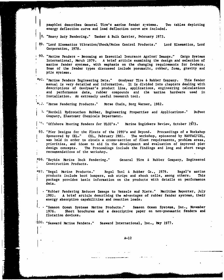
pamphlet describes General Tire's marine fender systems. Two tables depictingenergy deflection curve and load deflection curve are included.
i5. "Heavy Duty Fendering." Tanker & Bulk Carrier, February 1973.
i 89. "Lord Kinematics Vibration/Shock/Noise Control Products." Lord Kinematics, Lord"Corporation, 1978.
90. "Marine Fenders - Becoming an Essential Insurance Against Damage." Cargo SystemsInternational, March 1979. A brief article examining the design and selection ofmarine fender systems, with emphasis on the changing requirements for fenders.Some of the fender types discussed include pneumatic, rubber, foam, gravity andpile systems.
i*•1 "Marine Fenders Engineering Data." Goodyear Tire & Rubber Company. This fender
manual is very detailed and informative. It is divided into chapters dealing withdescriptions of Goodyear's product line, applications, engineering calculationsand performance data, rubber compounds and the marine hardware used ininstallation. An extremely useful research tool.
,5,. "Ybrse Fendering Products." Mbrse Chain, Borg Warner, 1982.
"Nordell Hydrocarbon Rubber, Engineering Properties and Applications." DuPontCompany, Elastomer Chemicals Department.
I f "Offshore ýboring Fenders for ULCC's." Marine Engirieers Review, October 1973.
95. "Pier Designs for the Fleets of the 1990's and Beyond. Proceedings of a WorkshopSponsored by CEL." CEL, February 1981. The workshop, sp6nsored by NAVFAC/CEL,was held in order to obtain a cross-section of fleet requirements, problem areas,priorities, and ideas to aid in the development and evaluation of improved pierdesign concepts. The Proceedings include the findings and long and short rangerecommendations of the workshop.
-96. "Ravkin Marine Dock Fendering." General Tire & Rubber Company, EngineeredConstruction Products.
*97. "Regal Marine Products." Regal Tool & Rubber Co., 1979. Regal's marinevroducts include boat bumpers, sub strips and shock cells, among others. Thispackage provides basic information on the products with details on performancedata.
' "Rubber Fendering Reduces Damage to Vessels and Piers." Maritime Reporter, July1981. A brief article describing the advantages of rubber fender systems, theirenergy absorption capabilities and reaction loads.
"- "Samson Ocean Systems Marine Products." Samson Ocean Systems, Inc., November1976. Short brochures and a descriptive paper on non-pneumatic fenders andflotation devices.
:100. .Seaward harine Fenders." Seaward International, Inc., May 1977.
A-12
I dim"

•I l"Seibu Dock Fenders." Seibu Polymer Chemical Co., Ltd., 1981. Seibumanufactures rubber fenders for a wide variety of marine applications. Seibu'smanual is a comprehensive guide to the company's product line. It includesdetailed performance data, photographs and diagrams.
('02. "Sumitomo Rubber Fenders." Sumitomo Rubber Industries, Ltd. Brief descriptionsof Sumitomo's full line of fenders, including pneumatic, rotary and rubber V-typeand D-type fenders.
13. "Survey of Naval Port Fender Systems." VSE Corporation/CEL, January 1980. A. . survey of Navy pier fender systems was conducted to evaluate the need for an RDT&E
program leading to improved fender systems. Eighteen major activities weresurveyed by mail and on-site visits were made to activities in San Diego andNorfolk. Among other problems, the survey revealed poor to fair conditions forpier fender systems, increasing costs and declining quality of timber materials.
4. "Survey of Naval Port Fender Systems. Berthing of Submarines, Aircraft Carriers,Hydrofoils and Surface Effect Ships." VSE Corporation/CEL, June 1980. This
_ -survey is a follow-on to the overall survey of naval port fender systems conductedfrom May 1979 to January 1980. This present survey provides information, data,conclusions and recommendations concerning fender systems and camels used forsubmarine berthing, aircraft carrier berthing, and berthing of hydrofoils and
surface effect ships.
*105. "Technical Manuals for Oreco Protective Systems." Oreco III, Inc., January
- 1982. Oreco III manufactures boat and offshore -platform bumpers of thi donut. type. Their brochure gives a brief description of their product.
.. _06'he Irving Marine Fender, Non-recoiling." Marine Aluminum Aanensen and Co., A/SHawgesund, Norway.
*107. "Uniroyal Marine Fendering Systems." Uniroyal, Inc. Uniroyal produces primarily
rubber fenders, small line of pneumatic. This comprehensive fendering manualincludes detailed descriptions of and extensive performance data for Uniroyal'sline of rubber fenders. Also included are results of full-scale testing, rubber
-I compound specifications and descriptions of marine hardware for installation.
_108. "Vredestein Industrial Products in Building, Dredging, Marine and Offshore."Vredestein Building/Dredging/Marine, 1981. Vredestein's marine manual reflectsthe varied character of the company. It includes detailed descriptions of andperformance data for Vredestein's rubber dock fenders as well as for dredging andsealing equipment.
" "Yokohama Pneumatic Rubber Fenders." Yokohama P ibber Co. Ltd., 1980. Acomprehensive manual describing Yokohama's line of pneumatic rubber fenders. The
.. manual contains photographs and diagrams of the fenders plus numerous tables andfigures depicting performance data.
A-13SDra m1

Appendix B
"1DYNAMIC RESPONSE OF THE SHIP AND THE BERTHINGFENDER SYSTEM AFTER IMPACT"
,B-
/11-i__ ___a__ __:~

S~~111 i
PROC. OF JSCE,11 No. 200. APRIL 1972
DYNAMIC RESPONSE OF THE SHIP AND THE BERTHINGI, FENDER SYSTEM AFTER IMPACT
By Sadao KOMAtsu* and Abdel Hamid SALMAYN"
where AfM=virtual .mass of the ship,
ABSTRACT 19 =virtual moment of inertia about theC) vertical axis through the ship's cen.This paper describes a mothod analysis for ter of gravity.
evaluating the portion of ship kinetic energy and V@ =velocity of translation,impact force transmitted to a berthing structure 'a =angular velocity.provided with fenders which have linear or non-linear spring constants. In the analysis, present. (2) The Effective Energy for Fender System
ed herein,4 the dynamic responses of the ship, IDsgfender and -berthing structure, after impact, are During berthing the kinetic energy of the shipconsidered, and derived equations for the selec. may be dissipated in several ways, among whichtion of different parameters needed for the solu. are the foilowing:tions of the dynamic equation• are included. i) Elastic deformation of the structure and
These are comprised of the virtual mass of the fender.ship, in both translational and rotational motion, ii) Swinging of the ship due to yawing mo-in addition to the time interval required for the tion.solutions of the motion equations by numerical iii) Heeling of the ship due to rolling motion.integration methods. iv) Elastic deformation of the ship's hull.
-v) Piling of the water trapped between the1. INTRODUCTION ship's hull and the face of the berthing
structure. (This occurs in the case of aSince the size of ships, particularly tankers, long closed structure.)
has increased in recent years, the design of off- Designers who are involved with marine struc.shore berthing structures has become more -m- tures design are interested in the portion ofportant. One of the prime difficulties facing de. energy indicated by i) which is called the effec.signers is the evaluation of the portion of .thip tive energy (E&). The problem of determiningkinetic energy and the impact force transmnirted the effective energy has been treated analyticallyto each of the fenders and the berthing struco by several investigators. Michalosl),i) treated theture, especially structures provided with rubber. problem as one which had a single.degree.of-like fenders, freedom dynamic motion, and considered the
theory of elastic impact in his analysis. The(I ) The Kinetic Energy of the Berthing Ship judgement of others,'),, including the authors,When a ship is approaching the berth with is that the ship's dynamic impact on the struc-
both translational and rotational motion, its kine. ture can be considered as a plastic impact, where,tic energy is given by the following equation; upon impact, both the ship and the fender sys-
S1 1 tem move together as one combined mass. VascoS...... Costal) has derived a dynamic equation for esti-
mating the effective energy in which only theProfessor of Civil Engineering, Osaka Uni- portion of the energy dissipated by the yawingversity. motion of the ship was considered. The rollingDoctorate Course Student, Civil Engineer. motion and the influence of the fender systeming Department, Osaka Univeasity (Eng. dynamic response were ignored. Hayashi andSuez Canal Research Center, Egypt). Shirai#) have dealt with the problem as one which
S" B-2* I
Sil|:iii i.
, ¾ ; it•lFI°Iii|ml

112 S. KomAiSU and A. H. SALMAN
has three-degrees.of.freedom dynamic motion; still a problem, especially in the case of fendersswaying, yawing, and rolling motion. The equa. with non.linear spring constants, and rubber.liketions are valid i) for structures which are pro. fenders, which are in this class, are being usedvided with linear spring constants, such as steel extensively due to their large energy.absorbingspring.like fenders. ii) for only one case of ap- characteristics.proaching mode of berthing, in which the vector The authors have presented a method of analy.of the approaching velocity is perpendicular. to sis based on the dynamic behavior of the system,
Sthe arm connecting the ship's center gravity with after collision, to evaluate the impact load andthe point of contact, the portion of the ship's kinetic energy trans-
Besides, the dynamic response of the fender mitted to the berthing structure and fenderssystem -was ignored. The empirical equation for which includes fenders that have both linear anddetermining the effective energy (&.) is also used non-linear spring constants. Also, to evaluatefor design purposes and is of the form the portion of the energy dissipated in the swing.
=CE, ...... (2) ing and rolling of the ship after impact.I where Be represents the approaching ship's kine-tic energy and C is the reduction or dispersion 2. DYNAMIC RESPONSE OF THE SHIPfactor. Pages") suggests the following equation AND THE BERTHING STRUCTUREfor determining for C; AFTER THE FIRST IMPACT
C=11/(1+16a) ...... (3)where a=d/l. L represents the ship's total length (1) General Mode of Berthinig
and d represents the distance between the ship's When the ship is approaching the berth undercenter of gravity and the point of contact, mneas- its own power, it is angled in to make the firstured parallel to the berthing face. Other design- contact with the fender system at a point nearers have selected a value of C which varies from its bow or stern. This point of contact is always0.2 to 1.0 depending on several factors, such as located in a horizontal plane higher than thatthe mode of berthing operation, local hull de. passing through the ship's center of gravity.formation, structure type, etc.2.S),-,?),) During this mode of berthing, the ship will
From published information it became clear undergb dynarmic motion which has three-degree.!shat the portion of the energy transmitted sepa. of-freedom, namely; swaying, yawing, and roll.rately to the berthing structure and fender is ing. The other motions, heaving, pitching and
--
Mir. I Behaviour of ship after contact.
B-3
• •- •=:d kb~-'• I I ll I I l [ am lie m l ~ le [ [[ [ [ [ [ [ [ ms l m || m m

JIDynamic Response of the Ship and the Berthing Fender Sstem After Inspac 113
surging are of little consequence in energy dis. Mjj,.Px-Kz.X 5-px.,_ (-i i ]sipation and may be neglected. .M...Pr-Kr.Ya-,uy..... (6)
(2) Equations of Motion In the previous equations the value of P is evalu-In the following analysis it is assumed that no ated from the given load-deflection relation (P-I .sliding contact is made along the fendei's surface. D) of the fender in question, The load is con-
Consider the motion of the ship, as a *free dody sidered to be applied in small increments atsoci.under the action of the load Pacting at the point ated with the time interval. This P-D relation"uof contact C, we have; is determined from statical analysis or tests. At
--At any time , after the ship came in contact any time 1, the deflection D will be calculatedA nwith the fender system s Fig. 1, its center of from the displacement of the point of contact Cwiththefener ystm, Fg. , is cnte of and the deflection of the structure, which will
gravity will sway in the direction of the acting e fl
load, to the position G. Then the ship will swing equal to;
about its vertical axis passing through C, an Dx=Xc-Xt " dangle 0 due to the yawing motion and finally it D). = Y- Ys awill roll about its horizontal longitudinal axis an ...... (7)angle #. Denote the coordinates of the final In considering the second impact, the velocitypositions of G and C, with respect to the axes of the point of the first contact at separation,X and Y, by (Xe, Ye) and (Xv, Y¢) respectively, magnitude and direction is needed, which willThe X and Y axes are taken parallel and nor. equal to;mal to the surface of berthing respectively.From the figure, the relation connecting the V 4 'Xc+'. . .
fender system motion at C with the motion of at=tan-3 (X•c2'Ic1)jG is; At time of contact a4=a, the angle that the ap-
keX=jtv+(r1+H0)cos(T+a) proaching velocity makes with Y-axis. a is con--Vc=P-(rI+H s) )I ...... (4) sidered positive when the velocity vector of V.
at G points towards the point of contact C.the second order terms in the above equation, If the value of the spring constant of the shipIs, 01 are neglected, hull at point of contact is available, the elastic
Consider the dynamic equilibrium of G, the deformation of the ship's hull can be evaluated.following equations of motion will hold; Let Kx, SA. and pA define the spring constant,
deflection, and the damping coefficient of thehull at point of contact respectively, then theMsX.=-Px-Rw"x equation of deflection of the ship's hull, in P-
WMse-Pr-Rwr direction, will be;
ii) YAWING "SA(P-KA.SA./J.SA)....... (9)& s-I=Pr.r.sin(T+a) ..... (5) In this case P will be function of (Xc, Yc, X,. Ys,
-Px.r.cos(r+*)-NZ S).. The initial conditions of motion, at time ofSiii) ROLLING contact, are;
I.. .•=(Pr.cos 41-Px -sin O)H X 9= Y@=8=0=XV= Yo-- • - W H,.- N•=X,= }8=SA=O.O
!C=.kCX= V, sin a ...... (10)Px, Pr and Rw, Rywr are the components of the!ender reaction and the water resistance, after kPe=kc=V cosa
:he ship came in contact with the fender system, 1#Xs=s=S5 0.0"espectively. N1 and Ns denote the water resis. The solution of dynamic equations is carried outa:nce to yawing a&-. rolling motions respectively, by numerical integration methods with the helpHlowever, as the time of contact is very small, of the digital computer.mater resistance, is safely allowed. Water resis.i nce is effective in the time between the first (3) Energy Equations.nd the second impact, this will be discussed in The developed previous equations are valid asletails in next paper. long as the ship being in contact with the fender.
As for the berthing structure response, the During this timt, the following energy equations'ollowing eq. will hold; are valid;
B-4

114 S. KOMAMIU and A. H. SAXLMA
I. Part of the ship's kinetic energy trans. ii) Ship (+fender)mitted to; k.,=-P/Mi
i) Fcnder Vj=iP.dDs in which P=K.r(Y,-Y,) and Y,.Y, are the dis.I placements of the structure and the poin. of
) Scontact respectively in Y.direction Fig. 1.ii) Structure V K1.dS. If, at the time of contact, the following condi.
[ I' tions exist;
iii) Ship's Hull V-- K.dS,, Y,=Y5 =0.0 4=0.0 3',=V1 ...... ei0t
=effective energy E, and assuming p=0.0, the analytical solution of
II. Work done by the ship in rotational these eq. (13) is given by;motions; Ys=A 3 sin pil+Ai sin pit
i) Swinging W,= P.r.dO,4 Ye=AiBssinpzt+A3Bssin
i HThe equations of energy become:m ii) Heeling W,,=ý','.do., ,V. =S ý'I,, Y,,dY. = .KYI?Ill. Part of energy induced in the system
vibration;
i) Ship a,%.=tM,(X',+Ye')................... -...... (16)
. =12K,[Ai(Ba-1) sin pit
2 2 +As(Bs-1) sin pi)lli) tuu-- M1 In the case of a very rigid berth, which offersi-) Sru -- a large resistance, the deflection Y, will be very
.......... . .......(1) small and, consequently, its ability for energyabsorption will be very poor, and can, therefore,
The above equations should satisfy the con- be neglected. In this case all the portion ofservation of energy during berthing i.e. energy consumed in the swaying motion of the
-I--- E+E + (2 ship should be absorbed by the fenders.il ,E,=-FMjV,'=Z,+Es,.+E, ...... (12)
NotationsT (4) Broadside Berthing ji.i=polar moment of inertia about
If the motion of the ship during the berthing the longitudinal axis (1-1)operation is mainly governed by tugboats, as is passing through the C.G.always the case with the large ships, the ship s..i=polar moment of inertia aboutcan make contact with the berthing structure the vertical axis (2-2) pass-entirely broadside. In this casc the ship will ing through the C.G.undergo dynamic motion which has two.degree Mi=the effective mass of theof.freedom; swaying and rolling, and terms con- structure.taining OP in equations (5) and (11) with vanish. M,=the virtual mass of the ship
If the energy dissipated by rolling motion is while swaying.neglected for safety, then the fender system P=the ship acting load.will be designed to absorb all of the kinetic H, Ri=the vertical distances betweenenergy of the ship, which is the case when C= the C.G. and the point of con.1.0 in equation (2). This mode of berthing is tact and the reta.center re-considered ideal as the ship impact load will be spectively.
. uniformly distributed on the structurell). r=the distance from the C.G. toIf we assume that the berthing structure is the point of contact.
provided with a fender which has a linear spring w=the ship's displacementconstant K7 the equations of motion will be; weight. • ..... (17)
i) Structure T-the angle that the velocityI (vector makes with the arm-__ __- J1,. • ..... (13) r at time of the first contact.
..5S,~I

Dynam.ic espsc of Me• ship and the BerthsIg ý'der System Aficr impaci i
X ,K ,=structure stiffness in X and than one approaching under its own power.Y direction. 2) Berthing conditions
pa, ps structure damping coefficients In the case where the berth is exposed to wind,in X and Y direction. waves, currents, etc., it is more difficult to con-
X-, Xi=the displacement of the struc, trot the ship velocity than in a sheltered berthture in X and Y direction. and the velocity may become large. However,
As: Vo/p,(B-EBs) for extremely high wind velocities in the order
AI i -A,_-_V.(B-,-Bs) of _00 to 120 mph that occur during short peri.p.,==(a+b)12TI(a+b)2+bcs, it is advisable to require ships to temporari-.IjBz=b/(pz'-a) ly anchor away from the berth in order to avoidBs=b1(ps1-a) being damaged")., l(Kj+Ks)IMz 3) Ship size
e sc K,/Ml Larger ships are always berthed with greatSIc=K;¢/Ms care and with the assistance of tugboats. It is
generally assumed that the larger the ship, the
3. SELECTION OF THE PARAMETERS smaller will be the velocity with which the ship
FOR SOLUTIONS OF THE DYNAMIC will contact the fender systems).II • iEQUATIONS 14.
The dynamic equations of motion presented in ,.0section 2 contain the following parameters; Zi H
for the ship, Va, Ms, I,.., I1-,. Hi,"for the structure. M,. K. sfor the fender, (P.D) 80 i ,, : , • • toot
and in practical design, the ship's displacement Ship displacement weightweight (IV) is, generally, the only value given
with the information for the marine structure to Fig. 2 Berthing velocity normal to dockbe constructed. vs. Ship displacement %-eight (after
This section includes equations, tables, and Lee).
graphs to help in selecting or computing the T. Lee presented the curves shown in Fig. 2unknown parameters for solutions of the dynam. from which the berthing velocity may be select-1ic equations. ed for design. Under various conditions of berth.
(1) Approach Velocity, V& ing, Vasco Costas" recommended Table 1 as a
From eq. (1) the impact energy is proportion. guide for the selection of velocity.
al to the square of the approach velocity. Thus, Before proceeding to the selection of otherthe energy level will increase considerably if the parameters, some relations concerning the ship
velocity is only slightly increased. In the selec. characteristics will be discussed. For example,tion of this velocity for design, many factors a tanker of length L, draft d and beam breadth
n I should be considered, such as: B, Fig. 1, will have the following empirical re-I•-• • 'lations:1) Method of dockingA ship approaching the berth under the con. W=caPLBd
trol of tugboats usually berths with less velocity c,=0.75 to 0.80-0.78
Table I Approach velocity of berthing ships_____________________ ft/sec)
i•E' iI" Ap Ic Dail,,men, ot the ship
Wind and swell Approach e
conditions, pt 3,000 ton Up to t,0.0on Over 30,0 ton
Strong wind and swell Dicult 2.5 2.0 1.5Strong wind and swell Iavourable 2.0 1.5 1.0Moderate wind and swell Moderate 1.5 1.0 0.8Protected Difficult 1.0 0.3 0.6Protected Favourable 0.3 0.6 0.4
II (after V. Costa)
* B-6
-... .. . . . *-

lit S. Koxasu and A. H. SA1Jw
Did=total depth/draft=l.33' 5 a ----- "L/D=23.75L/d= 18.25M=d-o.52=o:0,3, ...... (18) ' .. ,.•" ,
-'-=kwdiu, of gatioo about vertical.axis through G=0.2L$)
k.= radius of gyration about longi. @tudinal axis through GWnB
,,'I0.37 to 0.47,0.42 Fig. 5 Values of added mass coefficient C,ii •"i •"i •"N) jfor horizontal motion in deep water.(2) Derivation of Added Mam Equations for
Berthing in Shallow Water for typical tankers, Fig. 4 31), are considered in
1) Added mass in horizontal motion, MA the analysis hereafter.
It is well known that when a ship moves from With the help of the curves of Fig. 5 and these
deep to shallow water, as in the case when berth. sections, the distribution of the added mass along
ing, the added virtual mass is increased due to the ship length may be obtained (step 6 in Table
the presence of restricting boundaries. Koch") 2, and curve a Fig. 7). Considering the Koch
investigated the effects of shallow water on add- results for rectangular sections, and the proce.
ed virtual weight for both vertical and horizontal dure above, the added mass of actual hull shape
vibration. The measurements were made for a sections, where the ratio of water depth T to
block having a half-beam b and a draft d. The draft d is 2.0, can be evaluated (steps 7 to 10,
results of the experiments are shown in Fig. 3. Table 2). The results are shown by curve 6 of
To apply the Koch results on hull shape sections, Fig. 7).
it is suggested that the added weight to any However, the water depth considered by Koch
section of the ship, calculated for deep water for was deeper than that required for berthinig. The
this particular section shape, should be increased experimental results obtined by Marwood andby the ratio of the added weights in shallow and Johnson, Fig. 6 are of considerable help in this
deep water for a rectangular section of the cor- field1 s). This is bearing on the fact that the
rect beam.draft ratio and depth of water, percentage increase in C, in shallow water,* Furthermore, on the basis that many modern where T/d=2.0, than that in deep water for the
"•kers have very similar hull shapes, sections ship mid.sections (4-7), computed on the basis
* ~V.34 ,
e.1' I
C. T 4 41.WI
I!d,,!! . ......
iiiiiii .."; C.,. * P""" '
Fig. 3 Effect of shallow water on added massin horizontal vibration, Curves of Ci j "for rectangular section (after Koch). " I.,
IWAI "- L_\ L
Fig. 6 Effect of shallow water on added mass
Fig. 4 Actual sections of ship (after Kumai), '-(hlarwood & Johnson).
B-7

I:Ij
Dysimic Response of the Ship and the BerMisog.Fender System After Impad i17
Table 2 Evaluation of added mass in shallow water
Setio o. -0 1 ,h V1 , , ,23 4 1 I T 1 T 9 ,_ 9 11 4-1/ZbeamonW.L. 0.0 12.0 11.5 23.0 26.0 27.5 27.5 27.5 27.5 27.5 26.5 24.5 19.o 10.0 0.0
2 A-bxd Ud-20) 0.0 441 3618.5 493 546 577.5 577.5 577. 577. 577. 556. 514.5 39 210 0.0
3 S-Actual area 0.0 Ill 250.3 239.5 441.5 558.5 574.4 S74.4 S73.9 573. 536 S73.33 365.5 195 0.0
4 ,-Area. coeff. S/A 1.0 0.2S2 0.644 0.703 o.89 0.%7 0.995 o.09 0.994 0.9.4 0.963 0. 0.916 0.929 1.0
s 2/ld 0.0 1.143 1.762 2.19D 2.476 2.619 2.619 2.619 2.619 2.619 2.S24 2.333 1.810 0.952 0.0
6 CS, $Dep 0.0 0.49 0.42 0.42 0.405 0.44 0.46 0.46 0.46 0.46 0.44 0.42 0.415 0.41 0.0Fig.
I7Cg (Deep water) 0.0 o.4s 0 15 0.46 0.46S 0.46S 0.465 0.465 0.465 0.465 0.465 0.46 0.45 0.44 0.0
5 dlb 0.0 1.75 1.135 0.913 0.W6 0.764 0.764 0.764 0.764 0.764 0.79 0.857 1.105 2.10 0.0
CMo (Shallow W.)9 T/d-2.0 *-1 0.0 0.411 0.501 0.510 0.512 0.516 0.516 o.516 0.516 0.516 0.513 0.511 o.M 0.48 0.0
s Fi ag. 3
10 ICY.* 0.0 0.537 0.468 0.466 0.446 0.4811 0.510 0.510 0.510 0.510 0.485 0.467 0.463 0.4"7 0.0
CM_ otr M Ihlo I. III I II I
~1 MfrsalwW 0.0 0.886 0.772 0.769J 0.736 0.80 0.840 0.140 0.540o 0.840 0.80 0.77J .6 .3 .
of the Koch results, showed a close agreement W=I p ...(9with Marwood and Johnston's experimental re- 2
6, the derived values of the added mass coeffi. M,=m '. (20)
cients in step 10 are re.calculated for a water and the virtual moment of inertia Is-., in yawingdepth and draft ratio of 1.2 (step 11, Table 2 and motion will be"'."curve c, Fig. 7). h..=M~k1 ...... (21)
By integrating along the length and substitut.ing for d=B12.61 from Table 2, the following 2) Checking the derived formula
equation, for the added mass in horizontal vibra. Taking into account both model and prototype
tion. was derived; experiments, Vasco CostasO presented the follow.ing equation for estimating the virtual mass of
l I. • ' a berthing ship;
. .. M,=M+m,=m(,+2d1B) ...... (22)• I 1 I"- t ........ -...
Shu Tien Lil) also presented the following equa-
S. .. +/ •' ., , , •M=,JIM/(6z) ...... (23)V ti~n; M&=m(I+urB/(l6D)) (3-, -. ,,.4 I-- The virtual mass for different tankers, using
. -- - , .- -- 4- the three equations, was calculated, Table 3. ItC' .- I' ,""'.'"' can be seen that the derived equations yield re.
__ sults which are about 5A% more than the ShuT'ien Li equation and about 5% less than theVasco Costa equation.
&A ,3) Added mass of inertia in rolling motionThe added mass moment of inertia coefficients
Fig, I Distribution of added mass along depend upon the sectional shapes and the ratiolength. of beam to draft; the same parameters which
Ii B-8

::1
118 S. KOMA7SU and A. H. SALMAN
Table 3L -.
D/W I hI. .
Tankers to 17. M 111 tol~ tof to)0 00 330 140 1o7~o . .2• 7.9 2S 5o°' 3900 24® 70 9.0
20 X700 7 22.4 9.5 48O00 39000 47750 99.9300O0 40000 o 60 25.8 10.3 72000 59620 682M0 95.0
0OD 66037 11.4 114000D 103000 105700 92.535 ODD 113 O 260 3X.1 14.0 196000 173000 180o0D 92.0
100000 133000 285 141.2 S4.6, 223000 206700 213000 9i.0
iiVasC Costa Formula average: 95%11 Shu T'ien Li Formula
1illThe New Formula
To apply the results shown in Fig. 9 to thecase of a fully loaded ship, the following correc.tions are necessary; a) first, since we are inter.
. ,il?) ested in the moment of inertia (J,-1) about thecenter of gravity of the ship where v,/d=0.31,
-____-_;_;____ eq. (18), the effect of shallow water on the cen-
Fig. 8 Distribution of added virtual weight I -along length in torsional vibration T
(after Kumai). .
effect Cir. Also, these coefficients depend on the 0.4 .......location of the center of rotation. Model experi. Iments were carried out by Kumai on prismatic CV I = 1. Vmodels having sections corresponding to those ofa tanker',). Applying the experimental results I Lon the actual sections of a tanker ship, Fig. 4, - .J.Kumai obtained the distribution of the added -UU Imass moment of inertia along a typical tanker -- ri I 'hull in the loadeS condition, Fig. 8. By integrat.-_ Iing along the length, Kumni derived the follow. Iing expression; 0 i •
nJe=0.00531(I+0.365ddjr)B'L (ton-ml) Fig. 9 Effect of shallow water on added...... (24) mass moment of inertia in rolling
For a fully loaded tanker (d=dor). the above ex- (after Matsuura & Kawakami).pression becomes;
J-•=0.00725B'L (ton.m') I
...... (25) I LEq. (24) represents the added mass moment of 0.3inertia in deep water, but, as was discussed pre. C7 I I I /lviously, berthing always takes place in shallow -.-. L - I I -
waters. Therefore, the effect of shallow water Ion the inertial moment has to be considered. 1,
01 t I~ LMatsuura and Kawakamil'O performed numeri.cal computations, applying the finite element ""-
method, on the effect of the restricted water on 0 I
i the inertial coefficients, Cr. Rectangular sections V I IV ,.
having a ratio of half.beam to draft of 1.0 and Fig. 10 Variation of Cr with 'respect totwo locations of center of rotation, Vld=-0.0 and center of rotation for bidacl.0 (after1.5, were investigated, Fig. 9. Matsuura & Kawakami).
R-9

Dynamic Response of the Ship and the Zerthing Fýnder System After lJnpact 119
ter of rotation becomes Important. This is ob. eq. (24). Hence, for deduction, the C7 values oftained by companiag the inertial coefficienti, Cr, ship sections in shallow water (values includedat point as where T/d-l.2, Fig. 9, with point as in Fig. 8) can be multiplied by the ratio 0.064/0.06,in Fig. 10. That is, which denotes the Cr value in shallow water as
Cr.*1 Cr•S=O.l210.1=I.2 compared to deep water for sections 4 to 7. ThisSFrom which the value of Cr at ij.di0.31 and will lead, finally, to multiplying eq. (25) with the
T/d=1.2, namely Cr., will approximately be above ratio for obtaining the added mass moment
equal to of inertia, as follows, in shallow water;
(1h=0.00774B'L (ton.ml) ...... (28)Crv=.2(0056)0.07 ..... 26) The polar moment of inertia, Is, about a longi-
b) The second correction is obtained from the the par singetor ou t a toconsideration of three dimensional motion. Thecorrection factors from 2 to 3 dimensional mc- I,=m(kr)i
tion can be obtained from Fig. 11). If L/d= and substituting from eq. (18) results18.25, eq. (18). the correction factor correspond. J.=0.78pLBd(0.42B)3ing to pure rolling, (n=O), is equal to 0.96. Letting d=B/2.62 from Table 2, step 5, p=1.3Multiplying eq. (26) by this value yields; .ton/ml
Cro=0.067(0.96)=0.064 ...... (27) l,=0.0541BIL (ton.mS)
I ; I• -I4, I(J,)f(O.00774B4L)/(O.OS41B'L)=0.143J - ...... (29)
This ratio is in close agreement with the ratioS. .of 0.15 given by Prof. Hayashi). The virtuil.- 4 Jmoment of inertia I1-i becomes
r Fig. 11 Taylor correction factor from 2 to 1J-f=1.43m(zk)1=0.202Bim (ton'ml)
SL 3 dimensional motion. or J1 .•.i,+J,=.0Ol8B'L (ton.mi) Jc) The third correction is obtained from the -. . ..... (30)
fect of actual ship hull sections. A comparison 4) H1 or (-W, which denotes the vertical dis.was made with sections 4 to 7, Fig. 8, having tance between the ship's center of gravity, G,Cr in deep water equal to 0.06, and the rectan- and its metacentre, M, Fig. 1, can be calculated
gular.shaped sections where Cr in shallow water from the following equationW;was derived, eq. (27). From Table 2 the area B=LIC1+CM-(dlD)C9 ...... (31)
coefficient (a) of these sections is equal to 0.996 where Ci and Cs are constants having the fol.or about 1.0, giving a very slight effect due tothe round edges of these particular sections. lowing values for oil tankers (where K-/D=0.52);
The other sections have already been considered Ci=12.5 (U.shape)-13.2 (V.shape)
by the use of the equation derived by Kumai, C:=5.7
+ 45M
B-10
-' - -.- ., .'-

120 S. KONA7u and A. H. Si.LuAi
5) Effective mass, M1, of the structure-or determining the value of M1 that should be 4. SOLUTIONS OF THE DYNAMIC
subistituted in the motion equations. the authors EQUATIONS BY NUMERICAL IN-investigated some existing berths in Kobe harbor. TEGRATION
One is an oil berth belonging to the MitsubishiShoji Co. which consists of four dolphins of dif- The differential equations of motion of the shipferent sizes and a platform, Fig. 12. located back and the berthing structure are in the form of:from the berth line The berth is provided with Stuur =m PX .)V-type rubber lenders. The berth was designed Stuur X.fXPX X)X)to accomodate tankers varying in size (8 000 Ship120 000 and 47 000 DWT) under the control of i) roll O=G(0. P(X8, XC), it)tugboats. ii) yaw 0= Gi(, P(Xs, X.). 6)
a) The 47 000 DWT berths aga-nst two dol- iii) sway le= Gs(Xv. 1. J, P(Xs. Xe),Jphins which have-an effective weight equal to
cap+effective piles weight (CX) ...(3=2(160+180)=680 tans. (enA3)e x in section 2.)
b) The 20000DWT should use two dolphinswhich have an effective weight equal to In eq. (33) the first differential terms represent
210022rdeter 0 th eon. tthe damping effect which is generally neglected.2II+10)O theoions. eSolutions of eq. (33) are quite difficult to be car.c) The 800 t DWT should berth against two sed out analytically, especially In the case where
dolphins which have an effective weight equal to fenders (such as rubber) that have non-linear2(60+80)=290 tons. spring constants are used.
The displacement weights of the above ships A numerical solution implies the determinationare approximately (1.3hW) or 61000. 26 000 and of the displtcement and velocity of a system a.s10 400 tons, respectively. The virtuah masses a o mc e
(Mg)wil be qua to104 00,48 00 ad ~ velocities are 6btained in a step-by-step Integra-tons, respectively, Table I and the ratio MI tion procedure, starting with given initial condi-
will be equal to 680/104 000=0.007, 440/48 ODD tions. There are many different methods of0.009, and 2 8025000=0.0n1. numerical integration from which two methods,
MI/M=0.0 ..... 32) the Nlewmark Pi method'O and the Runge-Kutta-MGill method"), will be explained.
Thus for the first design approximation, we canassume that Mv will be as much as w IA of the (1) Time Interval Effect on the Two Numeri-virtual mass, Mi. of the approaching ship. If, cal Integration Methodsat the end of the calculations, the difference be- Tests have been conducted to study the effecttween the derived value of Al3 and the assumed of the time interval on the accuracy of the twovalue is great, the calculations can be repeated methods. In these tests, fenders with linearusing the derived value for MI. spring constants were used. for which the exact
6) Structure and fender resistance solution of the equation of motion is obtainedAs discussed previously for the design of marine by using eq. (15). Through the comparison of
structbres, the function of the structure should results which are included in Table 4 and Fig.be known in advance in addition to the ship dis. 13, the following conclusions could be made:placement weight. In the selection of the resis. 1) The error involved in fender absorbed ener-tance (.s) of the structure, the structure func. gy. 1'p. is relatively small compared to thetions, whether rigid or flexible. should be con- energy Vs absorbed by the structure.aidered. If the berth carries heavy l*ads (heavy, 2) The percentage of error involved in the VsSdelicate equipment carried on the deck, cranes, values is nearly twice that of the structurepower station, etc.), there is no choice; deflection maximum deflection, X1, i.e. iVn tialco1%.must be limited. Tle construction should be 3) For the same time interval the error in-
It rigid and provided with elasticfenders to absorb curred using the RungeyKutta-Gill methodthe ship's kinetic energy. On the other hand, is greater than that Involved in the New-if deflection is allowed, the berth can be flexible, mark P method. The difference also in.
IA
-B-l

Dy~mamic Response of the Ship and the Berthing Fender System After Impact 121
0a w so -- i V! O
ii. ii' i0
- " "
.1,
""EI KViT=I ..
II a 44 IIIII, @4. #1,
0 00C
.L . , I.*B.1
ii O l"I i- I - -,*- • - .,, .. -"
.3nn- .I .3 - I3 - ,'1 I "1
!!iii :
... . ; E I il .E I E II ~ E ~ E i
0I= l I I =I.. .. ... ,• .i-i i ii : _I-, I,
I i l4, , ,
_:-_-' -_ __"_.... . .
'*III t. " ,__ _ _ _ _
*0 III
-lII* *,
SI I I t.... . . . ... . . . . .
iii ii []12
iii i i i

interval variation, the berthing data, and theerror involved in the maximum deflection of theberthing structure was developed.
The curves shown in Fig. 15 were plotted fromFig. 14 for an error equal to 2% of the struc-
-- - -- TA..__. ture maximum deflection. This gives 2% error
-.,. . . in the structure maximum reaction (KsX,) andnearly 4A; in the structure's stored energy. In
... " , , , this figure the x.axis represents the berthingI 8•" " 94 30 3 data, which is the factor N, and the y.axis re-; _A -I . - 3 presents the time interval 41. The factor N is
"M ._ W 3S a function of the ship's virtual mass, the struc-ture's effective mass, the structure and fenderspring constants, and the ship's approachingI. Ivelocity according to the following equation;N=(AaIMAjXIO0) (cm) ...... (34)
-.- Iwhere As is obtained from eq. (17).i- ,..-' From Fig. 15 the relation between JV and the
time interval i1 for an error of 2A; in iXi is- --_. _ __.-.---.--.----------. _given by:
AIM t in. i) The Newmark P method (0=1/4)Fig. 13 Convergence of error with respect(sec). (3)
to time interval. 41= 3. 73,•II! •I I I 1=O.OO01SN'-.O.OO29N' .
(2) Selection of a Suitable Time Interval +o.018N-o.0313 (sec) . (36)Through many investigations carried out by N :3.73
the authors, Fig.e4, a formula linking the time ii) The Runge-*utta.Gill method
a-NW8 ' Method1K~ lN TM, V I
_II i9i- 6-Y. /- b-. h.. Ku l1 241K 30 0. 0 * 21 tI+--- -- nI+I " M, I •++ +
4 .
0,5 is I A'
- L_ soo 0.91 41747
•I I I I I 10j 60 1, 1 ,+ ;"7 in 4.5 t 1 '. I 4.7S4120 a ii W".
10 _ WE 2.2#u~-. _ - - i
00 i lieI 0__-.
,i. ,..5 0.40, o.., 0.00S 0.M&... . T in• see* &T in we*
Fig. 14 Effect of time interval on the berth structure max deflection for different cases"of berthing.
IB
-- -- - - - ll ii' --

:! IT>DWamic Raponse of the Ship and the Berthing Fender System After Impact 1it
newnuk DNI mom
- anae.Ea4&, M,.ed .. . 5. APPLICATION
(1) A Caue of General Berthing and Fendersf &T~wo JW- WNa o Non41naear Spring Constant
7- - a) Data Given;------. A tanker ship of displacement weight W
. -•=40 000 ton011 * ýr-~ Approaching velocity V,=15 Cm/aec
III II0' •, l61 Ship characteristics are;,--W4&NIg*-j* Length=200 .m Bread:h=25.8m
- --' - -,. Draft=10.81m
Berthing data;S~r=80m H--3.0in 7"=50" a=200., - - - Assuming, for the first trial, the fender system
data as;"s=15ton/cm Fender=2 pieces of type I,
S ' " Fig. 17.1I .". " .. b) By applying the formulas included in sec.
Fig. 15 4T, vs. N for 2% error in berth tion 3, the following data was computed;structure max deflection. . Ms=70.69 ton.sect/cm
i l=0.0018 (sec) .. ..... (37) 0N=g3.73 • . !
41=0.000066N'-0.00137Nsl II. +0.oo0sN-0.0178 (sec) ...... (38)
N 3.73....(3) Application to the Non-linear Spring Con. ,..:
start Fenders
Both rubber and retractable fenders possess -- -..non.linear relations between the load and the C .1 .A Adisplacement. To apply the preceding equationsfor selecting the time interval for structuresprovided with these type of fenders, the load isconsidered to be applied in small increments as- C.1.1 &4.a4sociated with the time interval. The procedure A
for calculation is as follows:.. , . .
1) The spring constant (Ks) of the fender corre-sjponding to zero displacement is taken fromthe given load-displacement relationship. .....
2) The factor N can be calculated and. con-sequectly, the time interval from eqs. (35),(36) or eqs. (37), (38):
3) Substituiing in the equations of motion,-•ie displacement of the fender at the endof the interval can be obtained.
-- 4) The spring constant corresponding to thisdisplacementcan "be" calculated as indicated .in step 1).
- 5) Repeating steps 2), 3). and 4) until the al- Fig. 26 Flow chart for design procedure by* I i . lowable fender displacement is reached, using newmark "s' method.
B.44
,1 iii ii

• "i, 124 S. KOMATSU and A. H. SALMAN "
Table 5
r X.K Fender Effectivec,& *MCaeMdI etigT energy soNo _ _ m ton/cm Fig. 17 awl- se e-
I General berthing : I0 3 is Type _41.7_ _2.6 0.1112 +0._1 X1 * X 10- 2 l -
-•2 No-rolling 0 is 42.09 $3.44 \
I0 T e 6.25 X.70 52.5
Feeer of linear
s ang coflant Kr,,O0ton/m V.60 $7.7 Tables 3 and 4. .C refer. 4)
The fender stiffness used In these cases is chosen by trials to give Ie"C.0 at max. xway•. MaI30tonostc2/cm. V.o.l0cm/sec
.Xrthe combiund stiffness of the fender system"-K.Kj/(X,+Kj)
M=0".7ton-secf/cm " 1 ' ' "H"'AH=M=2.27m 2
_-2=54 x 106 ton.secS.cm-
J,-a=1l3xI0?ton-secl-crn% +.2 sjI~#c) For numerical integration, Newmark • substituting 'for 6 aid • their values,
method with P=2/4 was used. Besides, equations 0.nlIzx0-' and 0.151x 0-'sec1- re-(35) and (36) were applied for selecting the time spectIvely, we obtain;" - : .. .interval. Calculations were carried out by the ectively, weotim-digital computer, the flow of computations is , ( ishown by the block diagram Fig. 16. Results is Structureincluded in Table 5. •
(2) Besides, for comparing the presentediiii ii..-:
L method with other investigators methods, two -2I x 0.7 x (-4.659)3/100=0.077other examples were tried, Table 5. (ton.n)
- " -+E, =37.26+0.077=-37.3 (ton.nr)6. COMMENTS ON THE RESULTS TS.... =I .Total energy at Vo=:O.O~willl'*b";"
S+.E 1 +E,=79.09 (tonlr) : .. (39)(1) Verification of the Developed Method of
But the ship's approaching energy is;
7o verify the assumptions presented in estab- E,-=1x70. 69x11 /,00=79.520 (ton-m)lishing the dynamic equations included in section• ; ; - ., " . .. ,-. .. ' .. :..... (40)2, conservation of energy before and after colli.sion is checked from the deduced results. Eq. (39)-Eq. (40) which satisfied the conserva.
- -o the in c n .. tion of kinetic energy before and collision.1) Consenrotion of tekntceeFrom Table 5 we have at V.=0.09*0• .. _: 2) Counseraion of the moment of momentumQ Part of the ship's kinetic energy transmit. i) At time when the ship made the first con.
ted to:. ... tact, the moment of momentum is given
Fender system=Effective energy by;F.t=41.79 (ton/m) MMi=M,.V,.rsln'. "
I-ii) Part of energy induced by the system vi- .sm7O.6ixI5x8O00' 076611C00S_- .-.- • ! ~ ~~bration.:-". .. : ""...Ship .... .' "." m649.8x01t (ton.s-,.nm). •
(41)
I1-T 7 - .30 Ii) At time when th4 81ip starte'd to rebound,II;.. .. " "the moment of momentum' "equal to;
1312+ 4111 -I-- """ . M 0h•+44+Ms .
at W'0.0 this eq. yields to; -=26.,OxIO'+LIsxIo'
IBam Ii
-- -15
i ll ms

Dynamic Response of the Ship and the Berhing Fender Syslem After Impac 125
I +527.80X10=662.05x10s (ton.sec.m) 7. COMPARING THE METHOD WITH
...... (42) OTHER INVESTIGATORS METHOD
Eq. (41)=Eq. (42) which satisfied the moment i) Case 2. Table 5, in which H=O.O, is Simi.of momentum principles. Jar to the case treated by Vasco Costa, i.e. sway.
ing and yawing motions are only considered.(2) Checking of Time Interval Selection Proce- From the table we have; at Vc=0.69•0.Ocm/sec.:: : •dure--(Vat-l Vsy+ Vfr)--(l8.40-13.42-120•2•)i"-The accuracy of the deduced results, as seen -42 .0 + . ......(4)
in the previous paragraph, verified, on one hand, =42.09 (ton/r) (43)the right procedure of developing the equations Substituting with the given data in the equationof motion, and on the other hand, it supported given by Vasco Costa, we obtain;the author's recommendations for the evaluation E'W I1 MV kt2+rleosi4of the time interval AT presented in section 4. ,sV,Fig. 18 shows the variation of AT through the =42.15 (ton/i) .(44)numerical integration process acoording to thevariation of the fender's stiffness shown by Fig. ii) Case 3 is similar to the case treated b v_ _17. Any is-coice of the time interval will lead Hayashi & Shirai, i.e. fender of linear springto large errors, and sometime, leads to unreason. constant and T, Fig. 1. equals to 90%
_ able results as included in Table 4. From i) and ii), if we considered some errordue to numerical integration, the author's meth.32=0o 4•. -d will be in agreement with the two special
i- -- - - cases treated in references 4) and 5).
-I-20s 8. SUMMARY AND CONCLUSIONS
-F PD - The foregoing study describes an analyticalL 3i treatment of the ship berthing problem, basedZ aon the dynamic response of the ship and the
-o -/ ,4 - fennder system during berthing.0J __ The presented analysis covers almost the main
z factors involving in berthing operations. These---- - -are comprised of;
i) The approaching mode of the ship with_ 90 U 0 W - n o I reference to the face of the berth, de.
Fig. 17 The load and energy vs. deflection ii) The location of the point of contact onfor V600H rubber fender (Tokyo the ship's hull, denoted by r and H.Rubber Dock Fenders). iii) The structure stiffness and the fender
stiffness, whether the latter of a linear or-I non.linear spring constant, beside to the
hull stiffness at the point of contact, ifCO • available.* - iv) The mechanical behaviour of the fender
-.. -system with respect to the variation ofethe acting load direction. This Is very
important in case of rubber.like fenders,- - -, as their energy absorbing capacity is a
-OW function of the load direction.*..) Consideration of shallow water effect in
0A .swaying, yawing and rolling._. S.0 _-For solving the developed equations of motions,Fig. 29 Variation of time interval AT vs. recommendations and formulas for estimationtime of berthing, and selection of the different parameters, partti
cularly the time Interval, are presented.
III1I11 3!-16

126 S. KOus.TSU and A. H. SALx.,,
I The solution of these equations will lead io 9) Vasco Costa: "Berthing Manoeuvres ofthe evaluation of the data required for design. Large Ships", Dock and Harbour Authority,ing the fender system; March 1968, pp. 351-358.
i) Evaluation of the energy absorbed by the 10) "The Construction of Quays and Jetties,"fender. Dock and Harbour Authority, Vol. 42, April
ii) Evaluation of the energy absorbed by the 1962.fender structure and its dynamic reaction, 11) Shu.t'ien Li: "'Operative Energy Conceptmagnitude and direction. in Marine Fendering", ASCE Proc. Paper
REFRE E 2875, August 1961, Vol. 87, No. WW3.REFERENCES 12) F. H. Todd: Ship Hull Vibration, Edward
1) James Michalos: "Dynamic Response and Arnold L. T. London, 1961, pp. 65-104.Stability of Piers on Piles", ASCE Proc. 13) Y. Matsuura and H. Kawakami: "Calcula.Paper 3221, August 1962, Vol. 87, WW2. tion of Added Virtual mass of inertia of
2) James Micbalo. and David P. Billington: ship", Journal of Zosen Kiokaf, J.S.N.A.,"Design and Stability Consideration for November 1968. (In Japanese)Unique Pier", ASCE Proc. Paper 2807, May 14) Y. Matsuura, H. Kawakami and H. Onogi:
. " 1961, Vol. 87, WW2. . "Study on the Coupled Torsional and Flex.3) Lymon C. Reese: Discussion on Paper 3221, tual Vibrations of Ships," Journal of Kansal
Reference 1) ASCE Proc. Discussion, May Zosen Kiokai, September 1969. (In Japanese)1963. WW2. 15) T. Sawvcmura: "The Determination of the
4) T. Hayashi and M. Shirai: Force of Impact Breadth of Ship Coupling GM and Did ra-at the Moving Collision of a Ship with the tio." Journal of Zosen Kiokai, J.S.N.A., De.Mooring Construction, Coastal Eng. in Ja. cember 1965. (!n Japanese)pan, Vol. 6, 1963. 16) Nathan M. Newmark: A Method of Compu.
5) F. Vasco Costa: "The Berthing Ship", Dock tation for Structural Dynamics". ASCE Proc.and Harbour Authority. Vol. 45, No. 523, Struct. Div. Paper 2094, July 1959.May 1964, No. 524, June 1964 and No. 525, 17) Norris and Others: "Structural Design forJuly 1964. Dynamic Loads", McGraw.Hill Book Co.,
6) Theodre T. Lee: "'Design Criteria Recom. 1959, pp..183-212.mended for Marine Fender Systems", Pro. 18) H. W. Reeves: "Marine Oil Terminal for"ceeding of Eleventh Conf. on Coastal Eng., Rio de Janeiro, Brazil". ASCE, Proc., Vol.Vol. 1, Part 2, 1968. 87, February 1961, WWI.
7) Lymon Reese and Michael W.: "Rational 19) T. Kumai: "Some Correction Factors forDesign Concept for Berthing Dolphins", Virtual Inertia Coefficient on the HorizontalASCE Proc. Paper 7291, May 1970, WW2. Vibration of a Ship ", Journal of Zosen Kio-
8) B. G. Tyrrell: "Mooring Dolphins", Dock kai, J.S.N.A., Vol. 108, 1960.and Harbour Authority, Part 1, August 1966,pp. 115-120, Part 2, September 1966, pp. (Received Sept. 2, 1971)261-166.
B-17
I .... _ -17