c h :: relays ,l:v i ' j/ . l:p· . com .. ·. ( l ·,i· 1' p ·1 ·zo mounting. scre.ws...
TRANSCRIPT
c
I. L. ijJ-659-A
Westinghouse " . /\·. I')' .
. l:P· .. ·. ( .. l � ' j/ J ,· �P
TYPES PS-I, PS-2, AND PS-3 PILOT'I I/. I' t4 . ..'··f·:· .· ·,i·�" (I
H �::,l:v RELAYS ,' y \/ J.1• 1' �·
./'? '• _, •. ·1 CAU TION
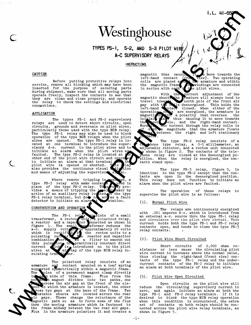
Before putt ing prote ct ive re lays int o service, remove all blocking which may have been inserted for the purpose of se curing parts during shipment, make sure that a l l moving parts operate freely, inspe ct the c ontacts to see that they are clean and c l ose properly, and operate the relay t o check the sett ings and e le ctrical connect ions.
APPLICATION
The types PS-1 and PS-2 supervisory relays are used to det e ct short c ircuits, open circuits, grounds and reversals on pi l ot wires, part icularly those used with the type HCB re lay. The type PS-1 relay may also be used t o block operation of the type HCB relays when the pilot wires are opened. The type PS - 1 relay is l ocated at one terminal to introduce the supervisory d-e. current t o the pilot wires and t o initiate a n alarm when the piLot wires are fault ed . The type PS-2 relay is l o cat ed at the other end of the pilot wire circuit and operates t o initiate an alarm at that terminal when the pilot wire is opened or shorted. This relay also provides the continuous visual indication and means of adjust ing the supervisory signal.
Where remote tripping is required, a type PS-3 relay with make contacts is used in place of the type PS-2 re lay . This relay provides a means of tripping the l ocal breaker by action of an auxi l iary relay l o cated at the type PS-1 relay terminal, but does not act as a fault det ector to initiat e an alarm at its stat ion .
CONSTRUCTION AND OPERATION
The PS-1 relay consists of a small transformer, a rectox unit, a p olarized relay, a reactor and a capacitor conne cted as shown in figure 1. The small transformer reduces the a-c. supply volt age to approximately 20 volts which is rect ified by the rectox units t o a pulsating current. The reactor and capacitor combination serves as a filter t o smooth out this pulsation to practically constant dire ct current which is introduced on to the pilot wires at the mid-tap of the t ype HCB re lay insulating transformer.
The po larized relay consists of an armature and contact mounted on a leaf spring supported symmetrically within a magnet i c frame . The poles of a permanent magnet c lamp directly to each side of this frame . Flux from the permanent magnet divides into two paths, one path across the air gap at the front of the e lement in which the armature is located, the other across two gaps at the base of the frame . Two adjustable shunts are located across the rear air gaps. These change the reluctance of the magnet i c path so as to force some of the flux thru the moving armature which is fastened t o the frame midway between the two rear air gaps . Flux in the armature polarizes it and creates a
-1 -
./ / magnetic bias causing it to ,tnove t owards the l eft-hand contact (front view<) . Two operating c o i ls are placed around the armature and within the magnetic frame. The windings are conne cted in series with each of the pilot wires .
With the correct adjustment of the magnet i c shunts the armature will always tend t o trave l t owards the north po le o f the front air gap with the coils deenergized. This holds the left-hand contact c l osed. When either of the operating coils are energized, the armature is magnet ized with a polarity that reverses the initial bias, thus causing it to move towards the south pole, and the right-hand contact. Normal ly, the current through the relay coils is of such a magnitude that the armature floats midway between the right and left stationary contacts.
The type PS-2 relay consists of a t e l ephone type relay, a 0-5 mi l l iammeter, an adjustable resistor, and a rectox unit connected as shown in figure 2 . The contacts of the te lephone re lay are c l osed at the deenergized posit ion . When the relay is energized, the contacts stand open.
The type PS-3 re lay, figure 3, is ident ical to the type PS-2 except that the contacts are open in the deenergized positi on. This relay does not function to initiate an alarm when the pilot wires are fault ed .
The operat ion of these rel ays supervise the pilot wire is as follows:
( l) . Normal Pilot Wire
t o
The relays are continuously energized with .001 amperes d-e. which is introduced from an ext ernal a-c. source thru the type PS-1 relay and cir culates over the pilot wire circuit. This current holds both the type PS-1 and PS-2 relay c ontacts open, and tends to close the type PS-3 re lay contacts.
(2) . Pilot Wire Short Circuited
Short circuits of 2,000 ohms resistance or less cause the circulat ing pilot wire current t o'increase above the normal value, thus c l osing the right-nAnd (front view) contacts of the type PS-1 re lay and the undercurrent contacts of the PS-2 relay to initiate an alarm at both terminals of the pilot wire .
(3). Pilot Wire Open Circuited
Open circuits on the pilot wire wi l l reduce the circulat ing supervisory current t o zero, and again initiate an alarm at both the type PS-1 and PS-2 re lay t erminals. If it is desired t o block the type HCB relay operat ion when this condition is encountered, the extra set of contacts on both re lays should be connected across the pilot wire re lay terminals, as shown in figure 5 . www .
Elec
tricalP
artM
anua
ls . c
om

115V. G;ON
TYPES PS-I, P5-2, AND PS-3 RELAYS
IOMF CA.PA.C.ITOR
PILOT W IR.£ -
CONNECT 11.'5 SliOWN If IT IS DE.SIR.£0 TO I!IL..OC.I<. HC.e. Rli!:L..A.Y W�£N PILOT WIRE.
IS OPEN.
®----1-1'----<D-1 AL�R�H���H2�--��----��AL�RM
[__ �--.!:)4--D-52.2.
REA.R VIEW
REA.R VIEW
Figure 5 External Conne ct ions for the Types PS-1 and PS-2 Relays.
11'4SULI'.TING TRANSFORME:.RS
IOMF tiJ.o,_---+-cAPACITO;;R;----I------'o.J
PILOT WIRE.
----15
TO HCe, RELAY
�R.MINAL'S
ICO
OPTION}\L TO -�..-...-r Bl.OCK HC B L---------+--1--. RELAYS_
115V. GON
AUXILI�RY ! CON'TII.C.TS NORMA.l.I..Y C.L..oe.E.o. A..\1'11.11...\A..RY CONTACTS 1-D- 20&7(11!£AQ.Ifoe-w)
I M.F, CAPACITOR. l'tE.MOTE.
TRIP NORMII\LL "'( OPE.I'ol·
Figure 6
.94-·l>-52� (ReAL�"''-')
Ext ernal Connections for the Types PS-1 and PS-3 Re lays.
-'+-
•
•
www . El
ectric
alPar
tMan
uals
. com

TYPES PS-I, P5-2, AND P5-3 REL�YS
�-oe--------7 !-k------�1 USE SC.�E:W 5 FOR THIN PANCLS rr·-----
\_ � DIA. DRILL (2-HOLE.S) 1�0-32 TERM.SCRlWS It STUDS -41 ·ZO MOUNTING. SCRE.WS
8:. STUDS
DIMENSIONS IN INCHE.S
Figure 7 Outline & Drilling Plan for the Types PS-1, PS-2, and PS-3 Relays in the Standard Projection Type Case. (See figures 1, 2 and 3 for Terminals Supplied.)
� 1>11\ HOL� Itt PI\I-IE.L (.'\\OLE. S) fO� SPE.C.IAL -a.\)\� . .SC. 7� 8
'j_ SAFE.T'f SW. (WHE.N UStt>) 2
.IS0-32. 1_:3* --·-�·- r--•if-s�
" j TE.RI"\. SC..
1/
r r I
=1.: I -:� I I') ,..,
� i I
I
/ -
, =::=;
'- - . I--lie
l--.2-l
.L� �b I
�� -=---?-�
fL r I I
- .i�
��� �7 I
�Jj I
2f
I
-1!:2 'It·
-leo
- .l.
ljk,./ I "lt'"
? �� � 'l:t Ill' -
1--2-!--l a ..La BR CI(.E.T I FoR l:k-PAtlEL I
l!o
3 �!(.; u � 1�---t � �'�liD ...3 a:l -l<t ......
l ! r-1 u- � �t CIO
� I I 'u 1--1.7 I �\ ;: I -tr. �- 1::1
) r�
BLADES VE.R n1tf',.\.. f>,.S , ......... _?< '1:119 -�J .. f-i• I' SHOW". 1\ISE.Rl C.OTH:.R f'lt\S
1\ Tt\£.N TI"\\1EN t\\llS. u
5-i c.R ��! i_ 0\�. t 4- OOL£.S) IM Pr-.�o�E.L fOR ,\90 -32. OPE.M\tl I� P�Mt.L .Sl
TttlM HO. SC.
Figure 8 Outline & Drilling Plan for the Types PS-1, PS-2 and PS-3 Relays in the Standard Flush Detachable Type Case for 1/811 Panel mounting.
PRINTED IN U.S.A. Westinghouse Electric & Manufacturing Company
Meter Division, Newark, N. J, 4-42 www . El
ectric
alPar
tMan
uals
. com

www . El
ectric
alPar
tMan
uals
. com

l.l. 41-659(
INSTALLATION • OPERATION • MAINTENANCE
INSTRUCTIONS TYPES PS-1. PS-2 AND PS-3 RELA {S
\ I
CAUTION Before putting protective relays remove all blocking which may into service,
have been inserted ror the purpose of securing parts during shipment, make sure that all moving parts operate freely, inspect the con-tacts to see that they are clean and close properly, and operate the relay to chec_k the settings and electrical connections .
The two capacitors serve as a filter to smooth out the pulsation of the re/eified c�u rent to practically constant di/ect curre which is introduced on to the pi11Qt '{ires t the mid-tap of the type HCB rel�y i�ulat g t::-ansform
,'er . . ·' /) .Q . � �
! t /''" · · ; T'i:,e po18.r1zed relay consists of an arma��
.. { f!.nrf" contact mounted on a leaf s ing su p.tfrted APPLICATION
.
/ · /�/ �' ,c•'"/'''· �l:nrnetrically within a magnet c
...
�r�
Ps 1 d Ps 2 .. i " 1 :poles of a permanent magnet cl mp , di The types - an - supel'v sory· ays ·· ;
.. /. ,- · ·each side of this�me:•"'"'Flu fr · e perma-are used to detect short ci�u1ts, open cir-/ nent magnet divid into t path , one path cuits, grounds and revers9's on pilot wires, -· !);
particularly those use�d /with the type HCB across the air ga at the f >· nt of t\he element
Th t Ps 1 i 1 t d t in which the a�mature is located, the other relay. e ype - r ay s oca e a one
terminal to introduce' the supervisory d-e. across two gaps at the base of the frame. Two
current to the pilot wires and to initiate an adjustable shunts are located across the
alarm when the pilot wires are faulted. The type PS-2 relay is located at the other end of the pilot wire circuit and operates to initiate and alarm at that terminal when the pilot wire is opened or shorted. This relay also provides the continuous visual indication and means of adjusting the supervisory current.
Where remote tripping is requjred, a type PS-3 relay with make contacts is used in place of the type PS-2 relay. This relay provides a means of tripping the local breaker by action of an auxiliary relay located at the type PS-1 relay terminal, but does not act as a fault detector to initiate an alarm at its station.
CONSTRUCTION AND OPERATION
The type PS-I relay consists of a small transformer with taps on the primary, a full wave Rectox unit, a polarized relay, and a potentiometer for grounding the d-e circuit.
The relay is also supplied with a 4 mfd. and a 10 mfd. condenser to be used with it as shown in figures 4 or 5 .
NEW INFORMATION !FORMER L L. 41·659-A REVISED)
rear air gaps. These change the reluctance of the magnetic path so as to force some of the flux thru the moving armature which is fastened to the frame midway between the two rear air gaps. Flux in the armature polarizes it and creates a magnetic bias causing it to move towards the left-hand contact (front view). Two operating coils are placed around armature and within the magnetic frame.
the The
windings are connected in series with each of the pilot wires.
With the correct adjustment of the magnetic shunts the armature will always tend to travel towards the north pole of the front air gap with the coils deenergized. This holds the left-hand contact closed. When either of the operating coils are energized, the armature is magnetized with a polarity that reverses the initial bias, thus causing it to move towards the south pole, and the right-hand contact. Normally, the current through the relay coils is of such a magnitude that the armature floats midway between the right and left stationary contacts.
EFFECTIVE 7-47 www . El
ectric
alPar
tMan
uals
. com

TYPES PS-1. PS-2 AND PS-3 RELAYS---------------
REAR VIEW
- TO STA'TION�V COHTAC"TS
TRANSFORMI!.R
PO\..A.R\ZEO ELEMENT
Fiq. 1-lntemal Schematic Of The Type PS-1 Relay In The Type FT Case.
The type PS-2 relay consists of a telephone
type relay, a milliammeter, an adjustable
resistor, and two Rectox units. The contacts
of the telephone relay are closed at the de
energized position. When the relay is ener
gized, the contacts stand open.
The type PS-3 relay is identical to the type
PS-2 except that the contacts are open in the
deenergized position. This relay does not
function to initiate an alarm when the pilot
wires are faulted.
CHARACTERISTICS The type PS-1 relay transformer has 100,
110, 120 and 130 volt taps on the transformer
primary. With tap voltage applied to the
transformer primary, the relay will supply
.00 1 ampere d-e to the pilot wire at approxi
mately 17 volts d-e at the output terminals.
This is sufficient to handle a 2000 ohm pilot
wire, and a type PS-2 or PS-3 relay adjusted
for approximately 15,000 ohms internal re
sistance with .00 1 amp flowing.
The type PS-2 and type PS-3 relays are ad
justable from roughly 9000 to 15,000 ohms.
The milliammeter has a 0-5 milliampere scale.
The type PS-1, PS-2 and PS-3 relays function
to supervise the pilot wire as follows:
( 1). Normal Pilot v.'ire
The relays are continuously energized with
J @)(
c @l )(
TEST :,wrrew P$-Z >II
A )(<!)
P>-2 >II B )(®
L.EPK*E T"t'PE RELAY
'T1!&T &WITC� cp 6t=TO R£l.AY
0 0 TO 8A!;E TER .. S �VI!.W
Fiq. 2-Intemal Schematic Of The Type PS-2 Relay In The Type FT Case.
.00 1 ampere d-e. which is introduced from an
external a-c. source thru the type PS-1 relay
and circulates over the pilot wire �ircuit.
This current holds both the type PS-1 and
PS-2 relay contacts open, and tends to close
the type PS-3 relay contacts.
( 2 ) . Pilot Wire Short Circuited
Short circuits of 2,000 ohms resistance or
less cause the circulating pilot wire cur
rent to increase above the normal value, thus
closing the right-hand (front view) contacts
of the type PS-1 relay and the undercurrent
contacts of the PS-2 relay to initiate an
alarm at both terminals of the pilot wire.
(3). Pilot Wire Open Circuited
Open circuits on the pilot wire will redu�e
the circulating supervisory current to zero,
and again initiate an alarm at both the type
PS-1 and PS-2 relay terminals.
(4). Pilot Wire Grounded
The connection of the separate windings of
the type PS-1 relay in each of the pilot wire
circuits provides two circuits of equal
impedance from the grounded midtap of the
potentiometer in the type PS-1 relay to the
remote terminal on the pilot wire. The type
PS-2 relay contains a relatively high re
sistance, such that when either pilot wire
becomes grounded at any 'point along its
length, unequal currents flow to operate the
type PS-1 relay. This provides supervision www . El
ectric
alPar
tMan
uals
. com
TYPES P8-l. PS-2 AND PS-3 RELAYS ______________ �'·-=-L.-'-41:....:-6=5 9-=- c
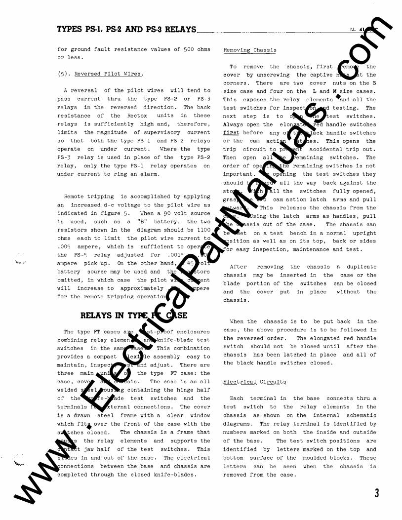
for ground fault resistance values of 500 ohms or less.
(5). Reversed Pilot Wires.
A reversal of the pilot Wires will tend to pass current thru the type PS-2 or PS-3 relays in the reversed direction. The back resistance of the Rectox units in these relays is sufficiently high and, therefore, limits the magnitude of supervisory current so that both the type PS-1 and PS-2 relays operate on under current . Where the type PS-3 relay is used in place of the type PS-2 relay, only the type PS-1 relay operates on under current to ring an alarm.
Remote tripping is accomplished by applying an increased d-e voltage to the pilot wire as indicated in figure 5. When a 90 volt source is used, such as a "B" battery, the two resistors shown in the diagram should be 1100 ohms each to limit the pilot wire current to . 005 ampere, which is sufficient to operate the PS -5 relay adjusted for .001� or . 002 ampere pick up. On the other hand, a 45 volt battery source may be used and the resistors omitted, in which case the pilot wire current will increase to approximately . 004 ampere for the remote tripping operation.
RELAYS IN TYPE FT CASE
The type FT cases are dust-proof enclosures combining relay elements and knife-blade test
switches in the same case. This combination provides a compact flexible assembly easy to maintain, inspect, test and adjust. There are three main units of the type FT case: the case, cover and chassis. The case is an all welded steel housing containing the hinge half of the knife-blade test switches and the terminals for external connections. The cover is a drawn steel frame with a clear window which fits over the front of the case with the switches closed. The chassis is a frame that houses the relay elements and supports the contact jaw half of the test switches. This slides in and out of the case. The electrical connections between the base and chassis are completed through the closed knife-blades.
Removing Chassis
To remove the chassis, first remove the cover by unscrewing the captive nuts at the corners. There are two cover nuts on the S
size case and four on the L and M size cases. This exposes the relay elements and all the test switches for inspection and testing. The next step is to open the test switches. Always open the elongated red handle switches � before or the cam
any of the black handle switches action latches. This opens the
trip circuit to prevent accidental trip out. Then open all the remaining switches. The order of opening the remaining switches is not important. In opening the test switches they should be moved all the way back against the stops. With all the switches fully opened, grasp the two cam action latch arms and pull outward . This releases the chassis from the case. Using the latch arms as handles, pull the chassis out of the case. The chassis can be set on a test bench in a normal upright position as well as on its top, back or sides for easy inspection, maintenance and test .
After removing the chassis a duplicate chassis may be inserted in the case or the blade portion of the switches can be closed and the cover put in place without the chassis.
When the chassis is to be put back in the case, the above procedure is to be followed in the reversed order. The elongated red handle switch should not be closed until after the chassis has been latched in place and all of the black handle switches closed.
Electrical Circuits
Each terminal in the base connects thru a test switch to the relay elements in the chassis as shown on the internal schematic diagrams. The relay terminal is identified by numbers marked on both the inside and outside of the base. The test switch positions are identified by letters marked on the top and bottom surface of the moulded blocks . These letters can be seen when the chassis is removed from the case.
3 www . El
ectric
alPar
tMan
uals
. com

TYPES PS-1. PS-2 AND PS-3 RELAYS _______________ _
RECTOX t)NITS
P>-3 I
f"S-'3 II
A )((!) • )(@
TEST �W\TCH
MILLIAM�ETER:
TELCP"''NE 1'YPE. RELAY
Fig. 3-Intemal Schematic Of The Type PS-3 Relay In The Type FT Case.
The potential and control circuits thru the relay are disconnected from the external circuit by opening the associated test switches.
A cover operated switch can be supplied with its contacts wired in series with the trip circuit. This switch opens the trip circuit when the cover is removed. This switch can be added to the existing type FT cases at any time.
Testing
The relays can be case but with the
tested in service, in the external circuits isolated
or out of the case as follows:
Testing In Service
Voltages between the potential circuits can be measured conveniently by clamping #2 clip leads on the projecting clip lead lug on the contact jaw.
Testing In Case
With all blades in the full open position, the ten circuit test plug can be inserted in the contact jaws . This connects the relay elements to a set of binding posts and completely isolates the relay circuits from the external connections by means of an insulating barrier on the plug. The external test circuits are connected to these binding posts. The plug is inserted in the bottom test jaws with the binding posts up and in the top test switch jaws with the binding posts down.
4
The external test cir.cuits may be made to the relay elements by #2 test clip leads instead of the test plug .
Testing Out of Case
With the chassis removed from the base, relay elements may be tested by using the ten circuit test plug or by #2 test clip leads as described above. The factory calibration is made with the chassis in the case and removing the chassis from the case will change the calibration values by a small percentage . It is recommended that the relay be checked in position as a final check on the calibration .
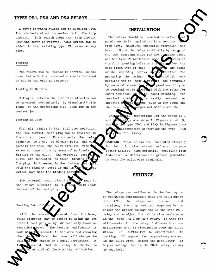
INSTALLATION
The relays should be mounted on swit8hboard panels or their equivalent in a location free from dirt, moisture, excessive vibration and heat. Mount the relay vertically by means of the two mounting studs for the standard cases and the-type FT projection case or by means of the four mounting holes on the flange for the semi-flush type FT case. Either of the studs or the mounting screws may be utilized for grounding the relay . The electrical connections may be made direct to the terminals by means of screws for steel panel mounting or to terminal studs furnished with the relay for ebony-asbestos or slate panel mounting. The terminal studs may be inserted by locking two
easily removed or nuts on the studs and
then turning the proper nut with a wrench .
The external connections for the types PS-1 and PS-2 relays are shown .in figure 4, and for the type PS-1 and PS-3 in figure 5. For information concerning the type HCB relay see I. L. 41-658.
CAUTION These relays are connected directly in the pilot wire circuit and must be protected against high potential resulting from induction or differences in ground potential between the pilot wire terminals.
SETTINGS
The relays are calibrated in the factory to be energized continuously with one milliampere
� ...1
www . El
ectric
alPar
tMan
uals
. com
-
TYPES PS-1. PS-2 AND PS-3 RELAYS _______________ ,_.L_4_1 -6_59_c
TO{� TYPE
HC.B RELAY
11 5 v e,o eve.
4 MFD
PILOT WIR.E5
} A:�RM J----t--t-• C. I R C. U IT }-+---11---+-
RECTOX \JNlTS
PS-2
REAR VIEW
T'fPE HC.B RELAY
TO }ALARM C..IRCUI,-
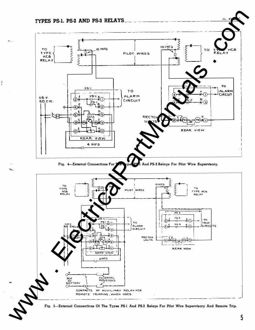
Fig. 4-External Connections For The Types PS-I And PS-2 Relays For Pilot Wire Supervisory.
TO TYPE
HC.B RELAY 0 PILOT WIRES
115V. E'>O CYCLES
4-MFD
o-+----t ..------,__ _ _,--sov.
DC BATTERY o�-----� ���--�------�
CONTACTS OF AUXILIARY RELAY FOR REMOTE TRIPPING,, WHEN USED.
RECTO X UNI"t5
Cl
REAR VIEW
TQ TYPE HC.B
RELAY
} TO TRIP CIRC. ITS
Fig. 5-External Connections Of The Types PS-I And PS-3 Relays For Pilot Wire Supervisory And Remote Trip.
5 www . El
ectric
alPar
tMan
uals
. com

TYPES PS-1, PS-2 AND PS-3 RELAYS _______________ _
"' ' -�I c��
11t If\ ··-� * r!�- " �
_LHTG �OLES � � -/·190·2>2 FOR .150 J)IA. SC. f SCREW (Zo,.4R-.:1)
]� �� t w
r- I
:!:.� TOL-E:RA.NCE ON ALL DIMe-NSIONS U"""l..E.SS OTHE.RWI'SE MARkED.
· A B C D E � l zf I 2.!. 2j I l!-
2 4 I 3! 3! I� I! 3 4 I! 3i 4§ I r I!
G
4 4 2! 3� 4e 1/o. I! It 5�! I d: \i i 1;: 102� 1 z.l:: J.!:i Jt. �-?;>� I Z43Y4 '/e )8 -
D A A6S1:• E.I"K.s.nL( CAP MF1). O.C.,VOL I �4S12Z.. I 1000
� .34312.1 4 <>OO
.3 .34-3125 5 1000
4 94312.1:d 10 1000 5 n .. 4-l�oo .. ,8 l!.'?>O
"":c':'?'i�l"'� t.as 1000
��':'c;.li�'fT 165 1000
H: '---- '-!- I T
Fig. 6-0utline And Drilling Plan For The Auxiliary 4 And 10 Mfd. Capacitors. For Reference Only.
d-e. After the relays are checked and installed, the only setting required is to select the proper voltage tap in the type PS-1 relay and to adjust the slide wire re�istance in the type PS-2 or PS-3 relay, so that the milliammeter in the relay indicates that one milliampere d-e. is circulating over the pilot wires. If difficulty is experienced in getting . 001 ampere d-e supervisory current in the pilot wire, select the next lower or higher voltage tap in the PS-1 relay, as may be required.
If pilot wires are subject to induction from adjacent transmission lines, it is recommended that the relays be set in the laboratory rather than while they are directly connected to the pilot wires. This precaution is to prevent injury to the personnel from high induced voltages. Neutralizing transformers are available for use to keep high voltages from the relay.
ADJUSTMENTS AND MAINTENANCE
The proper adjustments to insure correct
6
operation of this relay have been made at th9 factory and should not be disturbed after receipt by the customer. If the adjustments have been changed, the relay taken apart for repairs, or if it is desired to check the adjustments at regular maintenance periods, the instructions below should be followed.
All contacts should be periodically cleaned with a fine file. Style #1002110 file is recommended for this purpose. The use of abrasive material for cleaning contacts is not recommended, because of the danger of embedding small particles in the face of the soft silver and thus impairing the contact.
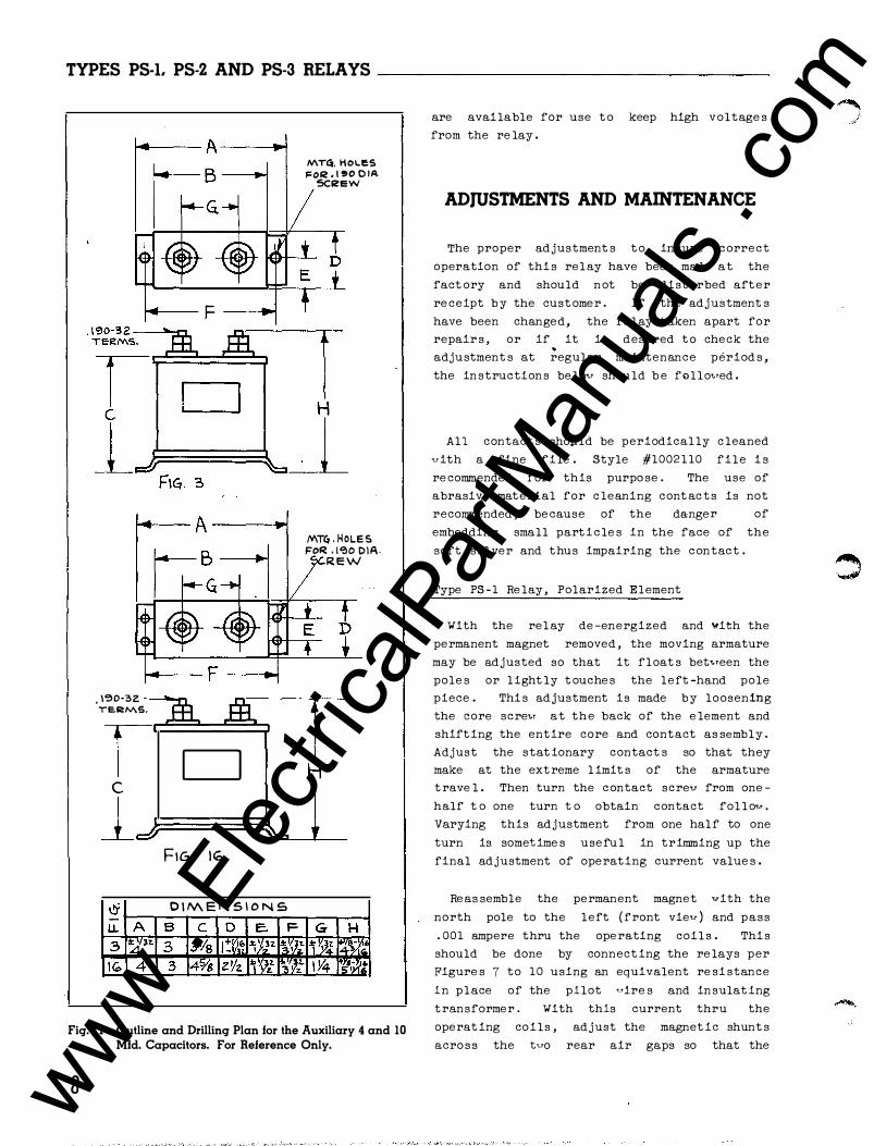
Type PS-1 Relay, Polarized Element
With the relay de-energized and with the permanent magnet removed, the moving armature may be adjusted so that it floats between the poles or lightly touches the left-hand pole piece. This adjustment is made by loosening the core screw at the back of the element and shifting the entire core and contact assembly. Adjust the stationary contacts so that they make at the extreme limits of the armature travel. Then turn the contact screw from onehalf to one turn to obtain contact follow. Varying this adjustment from one half to one turn is sometimes useful in trimming up the final adjustment of operating current values.
Reassemble the permanent magnet with the north pole to the left (front view) and pass .001 ampere thru the operating coils. This should be done by connecting the relays per figures 4 or 5 using an equivalent resistance in place of the pilot wires and insulating transformer. vlith this current thru the operating across the right-hand
coils, adjust the magnetic shunts two rear air gaps so that the
contacts close at approximately .0013 ampere, and the left-hand contacts close
at approximately .0007 ampere. With this adjustment, the moving contacts should float approximately �idway between the right and lefthand contacts at . 001 ampere.
For three terminal pilot wire applications, the contacts should float at . 002 ampere, close to the right at . 0023 to . 0024 ampere, and close to the left at . 0016 to . 0017 ampere. www .
Elec
tricalP
artM
anua
ls . c
om
-
TYPES PS-1, PS-2 AND PS-3 RELAYS _______________ ,._L_41_-6_s9c
tbiA. HDL£ {INIILL HDL� AS Nit TA6L f'()R THICK PA £L..
�------------ s'' ;....----sf-lf-'--+--
2.J 1------- 3 k-----.;
.. ,. ..... �, ...... T\tiCK ""'Na'-
-16 MJJi. STUD II
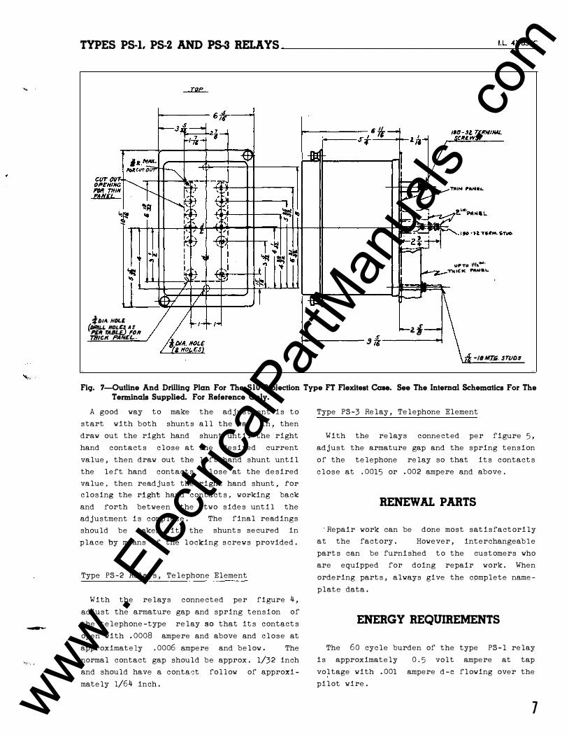
Fig. 7-0utline And Drilling Plan For The SIO Projection Type FT Flexitest Case. See The Internal Schematics For The Terminais Supplied. For Reference Only.
A good way to make the adjustment is to start with both shunts all the way in, then draw out the right hand shunt until the right hand contacts close at the desired current value, then draw out the left hand shunt until the left hand contacts close at the desired value, then readjust the right hand shunt, for closing the right hand contacts, working back and forth between the two sides until the adjustment is complete. should be taken with the
The final readings shunts secured in
place by means of the locking screws provided.
Type PS-2 Relays, Telephone Element
With the relays connected per figure 4,
adjust the armature gap and spring tension of the telephone-type relay so that its contacts open with . 0008 ampere and above and close at approximately .0006 ampere and below. The normal contact gap should be approx. 1/32 inch and should have a conta:::t follow of approximately 1/64 inch.
Type PS-3 Relay, Telephone Element
With the relays connected per figure 5,
adjust the armature gap and the spring tension of the telephone relay so that its contacts close at .0015 or . 002 ampere and above.
RENEWAL PARTS
Repair work can be done most satisfactorily at the factory. However, interchangeable parts can be furnished to the customers who are equipped for doing repair work. When ordering parts, always give the cpmplete nameplate data.
ENERGY REQUIREMENTS
The 60 cycle burden of the type PS-1 relay is approximately 0. 5 volt ampere at tap voltage with .001 ampere d-e flowing over the pilot wire.
7 www . El
ectric
alPar
tMan
uals
. com
TYPES P5-l. P5-2 AND PS-3 RELAYS ______________ _
TOP
'i--sl� L
"'F' 'I'" j;�
�� . I
r - A. � , ' , ' '� f �
i(j<lj � --- TDiNINIILS I
!:7-l'--1• l'--1•
�� ·:J--j �
./!11/J� .sc�
�--- -- _A. ... --, .� - 1-2-/!-
'r-6f '-::IS I'lL
�[ .JJID-5Z M1"0. 3C.
76" A
R.
i !/·
_ ..
1 ill
�I� 'IIi
::::1 "'� � v CVTOVT
OPENING INMNEL
J� ....
""'-.. I :f: PI-f. (4 NOLES)
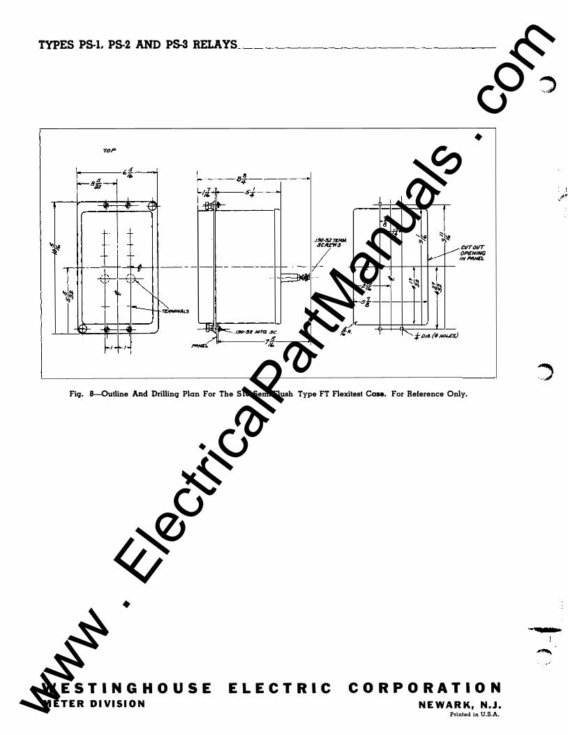
Fiq. 8-0utline And Drilling Plan For The S lO Semi-Flush Type FT Flexitest Case. For Reference Only.
WESTINGHOUSE METER DIVISION
ELECTRIC CORPORATION NEWARK, N.J.
Printed in U.S.A. www . El
ectric
alPar
tMan
uals
. com

I.L. 41-6590
INSTALLATION • OPERATION • MAINTENANCE
INSTRUCT IONS TYPES PS-1, PS-2 AND PS-3 RELAYS
(A-C OPERATED)
CAUTION Before into service,
putting protective relays remove all blocking ,,rhich may
have been inserted for the purpose of securing parts during shipment, make sure that all moving parts operate freely, ins�ect the contacts to see that they are c�an and close properly, and operate the rel�y .:to check the settings and electrical connections.
' /
APPLICATIO;�·
,ti j .�� /
The types PS-1 and Ps-l supe.rvisory relays are used to detect shot{ �ir�uits, open cir-/ cults, grounds antr versals on pilot ,.>fres, particularly those sed vith the type HCB
relay. The type P -1 relay is loca�t at one terminal to introduce the supervis ry d-e. I current to the pilot Pires and to i ,till,te
'·an 1
alarm Phen the pilot wires are fau e�. j The type PS-2 relay is located at the o her end o� the pilot r.rire circuit and operates to ipi'tiate an alarm at that terminal Phen the pilot· r.rire is opened or shorted. This rela)r"-·also provides the continuous visual indication and means of adjusting the supervisory current.
Where remote tripping is required, a type ___... PS-3 relay uith make contacts is used in place
of the type PS-2 relay. This relay provides a means of tripping the local breaker by action of an auxiliary relay located at the type PS-1 relay terminal, but does not act as a fault detector to initiate an alarm at its station.
CONSTRUCTION AND OPERATION
The type PS-1 relay consists of a small transformer Pith taps on the primary, a full vave Rectox unit, a polarized relay, and <t
potentiometer for grounding the d-e circuit.
SUPERSEDES 11. 41-659C
The relay is also supplied vith a 4 mfd. and a 1 0 mfd. condenser to be used vith. it as sho1.rn in Figures 7 to 10.
to cur-
rent to practical on��ant ,irect current r.rhich is int:t;.C:d-� t� 'the pilot vires at the mid-� · of t type HCB relay insulating transformer.
The polarized relay and contac�<mounted on symmetrically Pithin �.magn
•. ,dff·' poles of �,-;Jermantl4�agnet c each side -of this frame. Flux
divides
pported The
front ,rf the element armature is locafed, the other
acr� tr.ro gap5 at the base of the f�a e. Tup adjustable shunts areJ located \cr
. s �e
rear air gaps These �ange the r#lu ance of the magne c path, so as�o force s e of he flux thru he mov�g- �rritature Phich i
's fasten
ed to thEJ frame mid,.ray bebreen the two rear air gaps� Flux in the armature polarizes it and creates a magnetic bias causing it to move tor.rards the left-hand contact ( front vie,.r ) . Tr.ro operating coils are placed around the armature ar1d r.rithin the magnetic frame. The uindings are connected in series uith each of the pilot r.rires.
With the correct adjustment of the magnetic shunts the armature ,.rill alvays tend to travel tovards the north pole of the front air gap r.rith the coils deenergized. This holds the left-hand contact closed. When either of the operating coils are energized, the armature is magnetized vith a polarity that reverses the initial bias, thus causing it to move touard the south �ales, and the right-hand contact
EFFECTIVE OCTOBER 1948 www . El
ectric
alPar
tMan
uals
. com

TYPES PS-1. PS-2 AND PS-3 RELAYS _______________ _
TO MOVtNGC.ON!ACT
�����t6���� ����ED 6 "]e.eMtrtAL 10 AND IN, AT "TeltM1NAL... 9 TENOS TO C..LOS.E Tlo4E. R.H.(I=RONT 'VIe:W) C.OI<.ITAC.TS.
---TO S1ATIONARY CONTAC.IS
------ TE'S.I SWITCH
TRAt'\15FORME.R
\..1....�-----r-- FULL WAVE
REAR VIEW
FRONT VIE.W
RECTIFIER
PO\...AR\ZE.l> ELEMENT
Fig. 1-Internal Schematic of the Type PS-I Relay in the Type FT Case.
Normally, the current through the re lay coils
is of such a magnitude that the armature
floats mid,.ray bet,.reen the right and left
stationary contacts .
The type PS-2 re lay consists of a telephone
type re lay, a mil liammeter, an adjustable
resistor, and t•ro Rectox units . The contacts
of the t e lephone re lay are closed at the de
energized position . When the re lay is energized, the cont acts stand open .
The type PS-3 re lay is ident ical to the type
PS-2 except that the contacts are open in the
deenergized posit ion . This re lay does not
funct ion to init iate an alarm ,.rhen the pilot
vires are faulted"
CHARACTERISTICS
The type PS-1 re lay transforme r has 100,
110, 120 and 130 volt taps on the transformer
primary . With tap voltage appl ied to the
�ransformer primary, the rel ay vill supp ly
. 001 ampere d -e to the pilot vire at approxi
mately 1 7 volts d -e at the output terminals .
This is sufficient to handle a 2000 ohm pilot
vire , and a type PS-2 or PS-3 re lay adjusted
for approximate ly 1 5 , 000 ohms internal re
sistance vith . 00 1 amp fl o,.ring .
2
TRANSFORMER
FULL WAVE --"---RECTIFIER
REAR VIEW
WHEN NORMALLY ENERGIZED, CURRENT FLOWING OUT OF TERMINAL 10 AND IN AT TERMINAL 9 TENDS TO CLOSE THE R.H.(FRONT VIEW) CO.TACTS.
Fig. 2-Internal Schematic of the Type PS-I Relay in the Standard Case.
The type PS- 1 , PS-2 and PS-3 re lays function
to supervise the pilot vire as foll ovs:
( 1 ) . Normal Pilot Wire
The re lays are cont inuousl y ene rgized vith
. 00 1 ampere d-e . whi ch is int roduced from an
external a-c . source thru the type PS-1 relay
and c irculates ove r the pilot vire c ircuit .
This current holds both the type PS - 1 and PS-2 relay contacts open·, and tends to close the type PS-) relay contacts .
( 2 ) . Pilot Wire Short Circuited
Short circuits of 2 , 000 ohms resistance or
less cause the circulat ing pilot ,,,ire cur
rent to increase above the normal value , thus
closing the right -hand (front viev1 contacts
of the t ype PS-1 re lay and the undercurrent
contacts of the PS-2 re lay to initiate an
alarm at both terminals of the pilot vire .
(3 ) . Pilot Wire 0pen Circuited
Open circuits on the pilot vire vil l reduce
the circulat ing supervisory current to zero,
and again init iate an alarm at both the type
PS-1 and PS-2 re lay terminals .
I f
www . El
ectric
alPar
tMan
uals
. com

TYPES PS-1. PS-2 AND PS-3 RELAYS
"TEST ��lTCH " PS-z A�
@ )( >II )( <D c P>-2 •
@)( >II )(®
NILLIAMMET'f:R
/ "f"E.LEP\-ION.E TYPE �LAY �"!-, �� d'�����
RaAR VIEW "TEST 5WITC� qJ q:Jt=TO I<ELAY
6 0 0 "TO SASE TE.RMS FRONT Vl�W
Fig. 3---lnternal Schematic of the Type PS-2 Relay in the Type FT Case.
(4 ) . Pilot Wire Grounded
The connect ion of the separate ;.rindings of
the type PS-1 re lay in each of the p ilot ,,,ire
c ircuits provides tvo c ircuits of equal
impedance from the gounded midtap of the
potent iometer in the type PS-1 re lay to the remote terminal on the pilot vire . The type
PS-2 rel ay contains a relat ive ly
sistance , such that 1Jhen e ither
becomes gounded at any point
high re
pilotvire along its
length, unequal currents flow to operate the
type PS-1 re lay . This provides supervision
for ground fault resistance values of 500 ohms
or less .
( 5 ) . Reversed Pilot Wire s .
A reversal o f the pilot ,.,ires vil l t end to
pass current thru the type PS-2 or PS-3
re lays in the reve rsed direct ion . The back
resistance of the Re ctox units in these
re lays is sufficient ly high and , therefore ,
l imits the magn itude of supervisory current
so that both the type PS-1 and PS-2 relays
operate on under current . Where the type
PS-3 relay is used in place of the type PS-2
re lay , only the type PS-1 re lay operates on
under current t o ring an alarm .
Rct:rox UNtTs
REAR VJCW
l.l. 41-6590
MtLLIANHt:TCR TCLt:PHON£
TYPE ReLAY
Fig. 4--lnternal Schematic of the Type PS-2 Relay in the Standard Case.
Remote tripping is accomplished by applying
an increased d-e voltage t o the pilot vire as
indicated in Figures 8 and 10 . When a 90 volt
source is used, such as a "B" bat te ry , the two
resistors shovn in the diagram should be 1100 ohms each t o l imit the pilot vire cur.rent to
. 005 ampere , vhich is sufficient t o operate
the PS-5 re lay adjusted for . 0015 or . 002
ampere pick up . On the other hand , a 45 volt
battery source may be used and the resistors
omitted, in vhich case the pilot ,.,ire current
vill increase to approximate ly . 004 ampere
for the remote tripping operat ion .
RELAYS IN TYPE FT CASE
The type FT cases are dust -proof enclosures
combining re lay e lements and knife -blade test
svitches in the same case . This combination
p rovides a compact flexible assembly easy t o
maintain , inspect , test and adjust. There are
three main units of the type FT case : the
case , cover and chassis . The case is an all
'·'e lded stee 1 housing c ontaining the hinge half
of the knife -blade t est svitches and the
terminals for external connections . The cover
is a dravn ste e l frame vith a c lear •rind01.1
vhich fits over the front of the case ;.rith the
s1.rit ches closed . The chassis is a frame that
houses the rel ay e lements and supports the
3 www . El
ectric
alPar
tMan
uals
. com

TYPES PS-L PS-2 AND PS-3 RELAYS
COVE::�R:��: I�DICA,:r�O::_:R�-------� 5W\TC.H WHEN U5EC
REC1UX UNITS
"\ J "'-- , .• �I A )(CD PS·3 8
lf-1 ----')("'-@
FRONT VIEW
TES\ :::.W\TC�
MILLIAM)vlETER!
TELEJ>�E l'YPI:. RELAY
.....-RED HANDLE TO J?.E.LAY
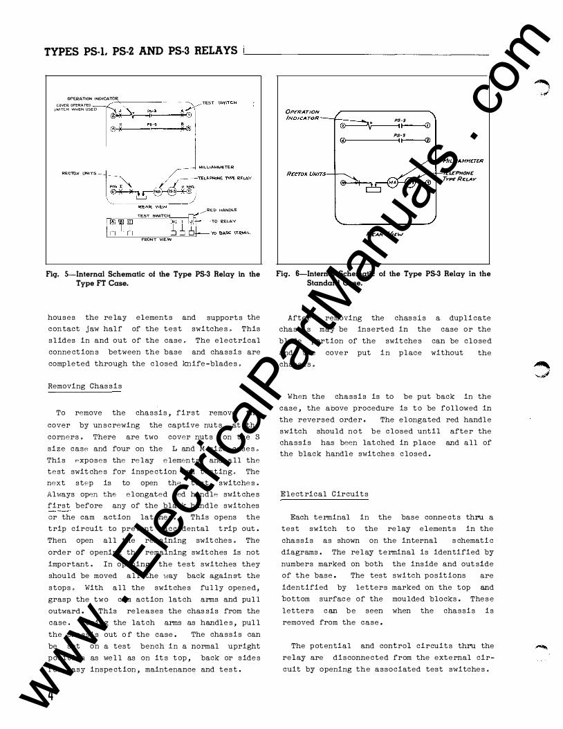
Fig. 5-Internal Schematic of the Type PS·3 Relay in the Type FT Case.
contact j au half of the t e st suit che s . This
s lide s in and out of the case . The electrical
conne ctions betveen the base and chas sis are
completed through the closed knife -blade s .
Removing Chas sis
To remove the chassis, first remove the
cover by un scre,.ring the captive nut s at the
corners . There are b.ro cover nut s on the S
size case and four on the L and M size case s .
Thi s expose s the re lay e lements and all the
test s'.rit che s for in spe ction and testing . The next step is t o open the test svit che s .
Ahrays open the e l ongated red handle suit che s
first before any of the black handle suit che s
or the cam act ion lat che s . This open s the
t rip circuit t o prevent accidental trip out .
Then open all the remaining suit che s . The
order of opening the remaining svit che s i s not
important . In opening the test s,.rit che s they
should be moved all the vay back again st the
stop s . With all the s�rit che s fully opened,
grasp the hro cam act ion lat ch arms and pul l
outvard . This re lease s the chassis from the
case . Using the lat ch arms as handle s, pul l
the chassis out o f the case . The chassis can
be set on a t e st bench in a normal upright
po sition as ue l l as on it s top , back or side s
for easy in spect ion, maintenance and test .
Aft er removing the .chassis a duplicate
4
OPERATION INDICATOR
MtLLIAMMCTER
Tea-PHONe TYPCRE:LAY
ReAR &-1cw
Fig. 6-Internal Schematic of the Type PS-3 Relay in the Standard Case.
chassis may be in seroed in the case or the
blade portion of the s�rit che s can be c l o sed
and the cover put in p lace ,.rithout the
chassis .
When the chassis i s t o be put back in the
case , the above procedure is to be follo;.red in
the reve rsed order . The e l ongated red handle
svit ch should not be c l o sed unti l afte r the
chassis has been lat·ched in p lace and all of the black handle suit che s c l o sed .
Electrical Circuit s
Each terminal in the base conne ct s thru a
test s,,rit ch t o the re lay e lement s in the
chassis as sho,,rn on the internal schemat ic
diagrams . The re lay terminal i s identified by
numbers marked on both the in side and out side
of the base . The test s,,ritch posit ion s are
ident ified by letters marked on the top and
bottom surface of the moulded blocks . The se
letters can be seen ,.rhen the chas sis i s
removed from the case .
The potent ial and control circuit s thru the
re lay are disconne cted from the external cir
cuit by opening the assoc�ated test s•r:±tche s .
A cover operated s•ritch can be supplied vith
it s contact s "'ired in serie s vith the t rip
circuit . Thi s s,.ritch opens the t rip circuit
www . El
ectric
alPar
tMan
uals
. com

TYPES PS-1. PS-2 AND PS-3 RELAYS-----------------=I=.L-'4-'--l- 6=5 ..:....::.9o
TO 0 TYPE
HCB RELAY
11&1/. €.0 c 'IC..
4 MFD
PILOT WIRES
PS-2 } A:�RM r--t-+-- CIRCUIT }--t--il--
RECTO X -1--f----:::-7-\J NITS
REAR VIEW
T'fPE HCB RELAY
TO }ALARM
C.IRCUI"T
Fig. 7-External Connections for the Types PS.l and PS-2 Relays in the Type FT Case for Pilot Wire Supervision of a Two Terminal Line.
TO T'I'PE
HCa RELAY 0 PILOT VoiiRES [] J-+---+---} TO
ALARM CIRCIJ\"T
R8::TOX ....1-..--jf-------:-..
4MFD
0,....+ __ ---i ..----,___ 90\f. DC
BAoTERY o-
C.ONTACoS OF AUXILIARY RELAY F'OR
REMOTE TRIPPING,, WHEN U'i>EO.
UNITS
P.EA� 1/IEW
TO TYPE HCB
Rf.LIW
1 TO TRIP Cl R.C. liS
Fig. 8-External Connections of the Types PS-1 and PS-3 Relays in the Type FT Case for Pilot Wire Supervision and Remote
Trip of a Two Terminal Line.
5 www . El
ectric
alPar
tMan
uals
. com

TYPES PS-I. PS-2 AND PS-3 RELAYS----------------
•rhen the cover is removed . Thi s svitch can be
added to the exist ing type FT case s at any
t ime .
Testing
The re lays can be
case but ,,rith the
tested in se rvice , in the
external circuit s i solated
or out of the case as fol l o,.r s :
Te sting In Service
Voltage s bebreen the potent ial circuit s can
be measured convenient ly by clamp:t . Jg #2 clip
leads on the projecting c l ip lead lug on the
contact j ar.r .
Testing In Case
With all blade s in the ful l open posit ion ,
the ten circuit test p lug can be in serted in
the contact j a,.r s . Thi s connect s the re lay
e lement s t o a set of binding post s and com
pletely i solates the re lay circuit s from the
external connect ion s by mean s of an insulat ing
barrier on the p lug . The external test cir-
cuit s are conne cted t o the se binding post s .
The plug i s in serted in the bottom test j a,.r s
heat . Mount the relay vert ically by mean s of
the bro mounting studs for the standard case s
and the type FT project ion case or by mean s of
the four mounting hol e s on the flange for the
semi -flush type FT case . Eithe r of the studs or the mounting
grounding the
nection s may be
scre,.rs may be utilized for
re lay . The e lectrical con
made direct t o the terminal s by mean s of scre,.r s for steel panel mount ing or
t o te rminal studs furnished ,.rith the re lay for
ebony-asbe stos or slate
terminal studs may
in serted by l ocking t'r.ro
panel mount ing . The be easily removed or
nut·s on the studs and then turning the proper nu"C vith a ·vrench .
The external connections for the type s PS-1
and PS-2 re lays are shovn in Figure s 7 or 9,
and for the type PS-1 and PS-3 in Figure s 8 or
10 . For informat ion concernin g the type
relay see I . L . 4 1 -658 .
HCB
CAUnON The se re lays are c onne cted dire ct ly
in the pilot ,.rire circuit and must be pro
tected again st high potent ial re sulting from
induction or diffe •ence s in ground potential
betveen the pilot vire terminal s .
vith the binding post s up and in the top test SETTINGS S'·'it ch j avs ,,rith the binding post s dovn .
The external test circuit s may be made t o the re lay elements b y #2 test c l ip leads in stead of the test plug .
Te sting Out of Case
With the chassis removed from the base , re lay e lement s may be te sted by using the ten circuit test plug or by #2 test 0 l ip leads as
de scribed above . The fact ory cal ibration is
made "'ith the chassis in the case and removing
the chassis from the case uil l change the
calibrat ion value s by a smal l percentage . It
is re commended that the relay be che cked in
posit ion as a final che ck on the calibrat ion .
INSTALLATION
The re lays should be mounted on s,.rit chboard
pan e l s or the ir equivalent in a l ocation free
from dirt , moi sture , exce s sive vibration and
6
The re lays are calibrated in the fact ory t o
b e energized cont inuous ly ,.rith one mil l iampere d -e . After the re lays are checked and
instal led , the on ly sett ing required i s t o se lect the prope r voltage tap i n the type PS-1
relay and t o adjust the s l ide ,.,ire re s i st ance
in the type PS -2 or PS-3 re lay, so that the
mil liammeter in the relay indicat e s that one mil liampere d-e . is c irculat ing over the pilot
,.,ire s . If difficulty is experienced in
getting . 00 1 ampere d-e supervisory current
in the pilot ,.,ire , se lect the next l o,.,.e r or higher voltage tap in the PS-1 rel ay, as may
be required .
If pilot ,.rire s are sub j e ct t o induction from
adj acent tran smi s sion line s , it is re commended
that the re lays be set in the l 2bor�tory
·rathe r than ,,rhile they are dire ct ly conne cted
to the pilot ,.dre s . This precaution is to
prevent in jury to the personne l from high
induced voltage s . Neutralizing t ran sformers
www . El
ectric
alPar
tMan
uals
. com
tl '!, I
TYPES PS-1. PS-2 AND PS-3 RELAYS _______________ ,�.L�4�1 -..:.;:65�9o
INSULATING TRA�;FO{RMER
TVPE HCB RELAV
I IS V. G;O eve.
Pl\..oT 'WIRES
INSULP..TI NG TR�NSFORMER
l T�PE ---J �CB RELAY
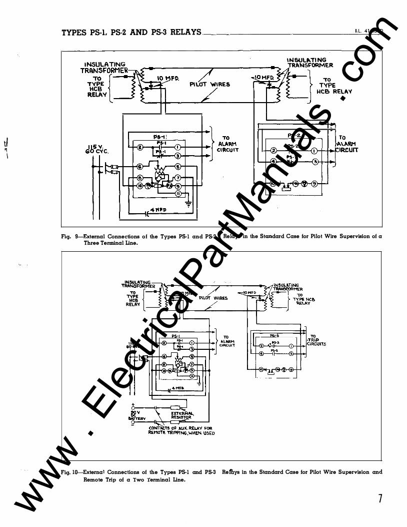
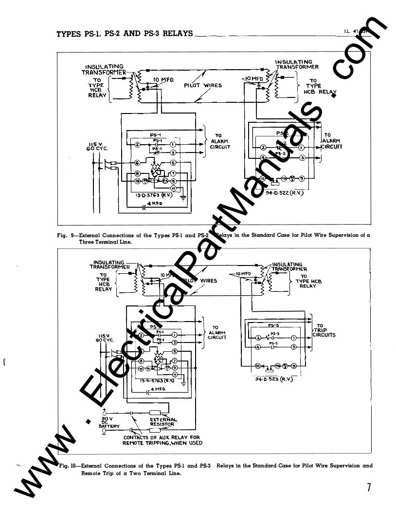
Fig. 9-External Connections of the Types PS-I and P5-2 Three Terminal Line.
Relays in the Standard Case for Pilot Wire Supervision of a
IN5ULATING TRA:FOR{MER T'IPE HCS RELIW
LH�_..it:---{10+-++} ��M CIRCUIT
++·1'-11:1-"H-{§)"""'
TO TRIP 't-<Y..."rlll----(j)--1-+._ICIRCUI"TS
Fig. 10---External Connections of the Types PS-1 and P5-3 Reffiys in the Standard Case for Pilot Wire Supervision and Remote Trip of a Two Terminal Line.
7 www . El
ectric
alPar
tMan
uals
. com
TYPES PS-1. PS-2 AND PS-3 RELAYS ----------------
,..__ __ F
F . I�0-3Z TE.RMS.
I D c 1
Flq. IG
l!i D I M E N S I O N S -u. A B c 0 E. F 3 '23Z. 3 3Vs ���]� �'}J_'Z. �{}i ' " 4 3 4% zYz i9.i ?,'�;
MT4. HOI.!:S FOR . 1 �0 O IA.
SCREW
MT4 . HOLE S FOR . l 'aO DIA.
R E W
f I H
G H iYl �� 1 Y4 r�·.�:
Fig. 1 1-0utline and Drilling Plan for the Auxiliary 4 and 10 Mfd. Capacitors. For Reference Only.
8
are available for use t o keep high voltage s
from the re lay .
ADJUSTMENTS AND MAINTENANCE
The proper adjustment s t o in sure c orrect
operation of thi s rel ay have been made at the
fact ory and should n ot be disturbed after
re ceipt by the cust omer . If the adjustment s
have been changed, the re lay taken apart for repair s , or if it is desired t o check the
� adjustment s at regular maintenance period s ,
the in struction s be lo,.r should b e follo�red .
All contact s sho�ld be periodical ly c leaned
uith a fine file . Style #1002 1 10 file i s
re commended for this purpo se . The use of
abrasive material for c leaning cont ac t s is not
recommended , be cause of the danger of
embedding small part i c le s in the face of the
soft silver and thus impairing the c ontact .
Type PS -1 Re lay, Polarized Element
With the rel ay de -energized and with the
permanent magnet removed , the moving armature
may be adjusted so that it float s bebreen the
pole s or light ly t ouche s the left -hand pole piece . Thi s adjustment is made by loosening
the core scre•r at the back of the e lement and
shift ing the entire core and contact as sembly .
Adjust the stat ionary contact s so that they make at the ext reme l imit s of the armature t rave l . Then turn the c ontact screv from one
half t o one turn t o obtain contact fol l o'·' ·
Varying this adjustment from one half to one
turn is sometime s usefu l in trimming up the
final adjustment of operating current value s .
Reas semble the permanent magnet ,.rith the
north pole to the left (front vie,.r ) and pass
. 001 ampere thru the ope rating coil s . Thi s
should be done by connect ing the re lays per
Figure s 7 to 10 using an equivalent re si stance
in place of the pilot ,.rfre s and in sulat ing
t ransformer . With this current thru the
operat ing coils , adjust the magnet ic shunt s
across the b.ro rear air gaps so that the
www . El
ectric
alPar
tMan
uals
. com
TYPES PS-1. PS-2 AND PS-3 RELAYS ______ ·------------'J=. L'-4:.:...1 -=6sc:.=.9o
right -hand contact s c lose at approximately
. 0013 ampere , and the left -hand contact s clo se
at approximate ly . 0007 ampe re . With thi s ad-
justment , the moving contact s should float ap proximat e ly mid•ray behreen the right and left
hand contact s at . 001 ampere .
For three
the contact s
terminal pilot ,.rire
should float at
clo se to the right at . 0023 t o
and close t o the left at
ampere .
app lication s ,
. 002 ampere ,
. 0024 ampe re ,
. 0016 t o . 00 17
A good vay t o make the adjustment is t o
start ,.rith both, shun t s a l l the vay in , then
dra,.r out the right hand shunt unt il the right
hand contacts close at the de sired current
value , then dra•r out the left hand shunt until
the left hand contact s c lose at the de sired
value , then readjust the right hand shun t , for
clo sing the right hand contact s , ,.,orking back
and forth bet,.reen the hro side s unt il the
adjustment is comp lete . The final readings
should be taken ,.rith the shunts secured in
place by mean s of the locking s :: re,.r s provided .
Type PS-2 Relays , Telephone Element
With the rel ays connected per Figure 4 ,
r I
t DtA DRILL FOR HUCK PANELS
.ii DIA.OKILL (2.-I-IOLES)
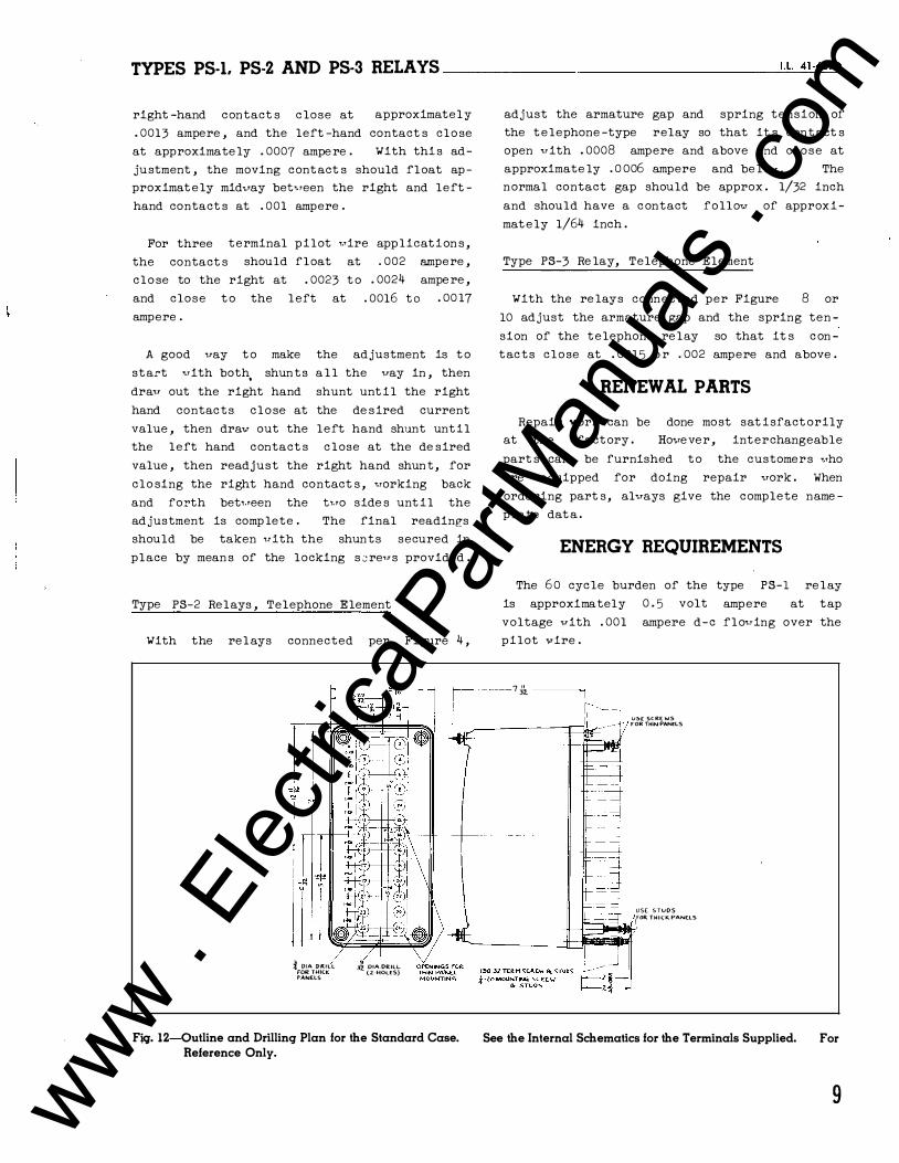
Fjq. 12-0utline and Drilling Plan lor the Standard Case. Reference Only.
adjust the armature gap and spring tension of
the t e lephone -type relay so that it s contact s
open ,.rith . 0008 ampere and above and close at
approximate ly . 0 006 ampere and be l o•r . The normal contact gap should be approx . 1/32 inch
and should have a c ontact follo"' of approxi
mat e ly 1/64 inch .
Type PS-3 Re lay, Telephone Element
With the re lays connected per Figure 8 or
10 adjust the armature gap and the spring ten
sion of the telephone re lay so that it s c on
tacts close at . 0015 o r . 002 ampere and above .
RENEWAL PARTS
Repair work can be done most sat isfact orily at the factory . Hovever , interchangeable
part s can be furnished to the customers vho
are equipped for doing repair vork . When
ordering part s, alvays give the complete name
plate dat a .
ENERGY REQUIREMENTS
The 6 0 cycle burden of the type PS-1 re lay
is approximately 0 . 5 volt ampere at tap
voltage ,.,ith . 001 ampere d-e flo,.ring over the
pilot vrire .
- ----7 & ___ _,
U�E SC.RE.WS FOR THIN PANELS
USE STUDS FOR THI<K PANELS
See the Internal Schematics lor the Terminals Supplied. For
9 www . El
ectric
alPar
tMan
uals
. com
TYPES PS-L PS-2 AND PS-3 RELAYS----------------
0
,190-.U. TE.RM. SCREW USE .190 �3z. 5TUD FOR CUT OUT FOR T H I C K. PA.NE.L MIG. S E M I - FLUSH
PA.NC.L LOCA.T\Oh ;f 0\A. HOLE DRILL
0
�0 I
PE.R. IH.TE.RNP..L SCHEM ATIC FOR PRO.JE.CT I O N MT� OM THICK PANE.LS.
t----- s � -STUDS F"OR PRO.J.
TYPE. MTG. ! DIA HOLE. (� REQ.).
i\-18 MT<O. STUD ( 2 REQ.)
i OIA. HOLE.$ FOR SEMI FLUSH TYPE.
MTG. (4 HOLES).
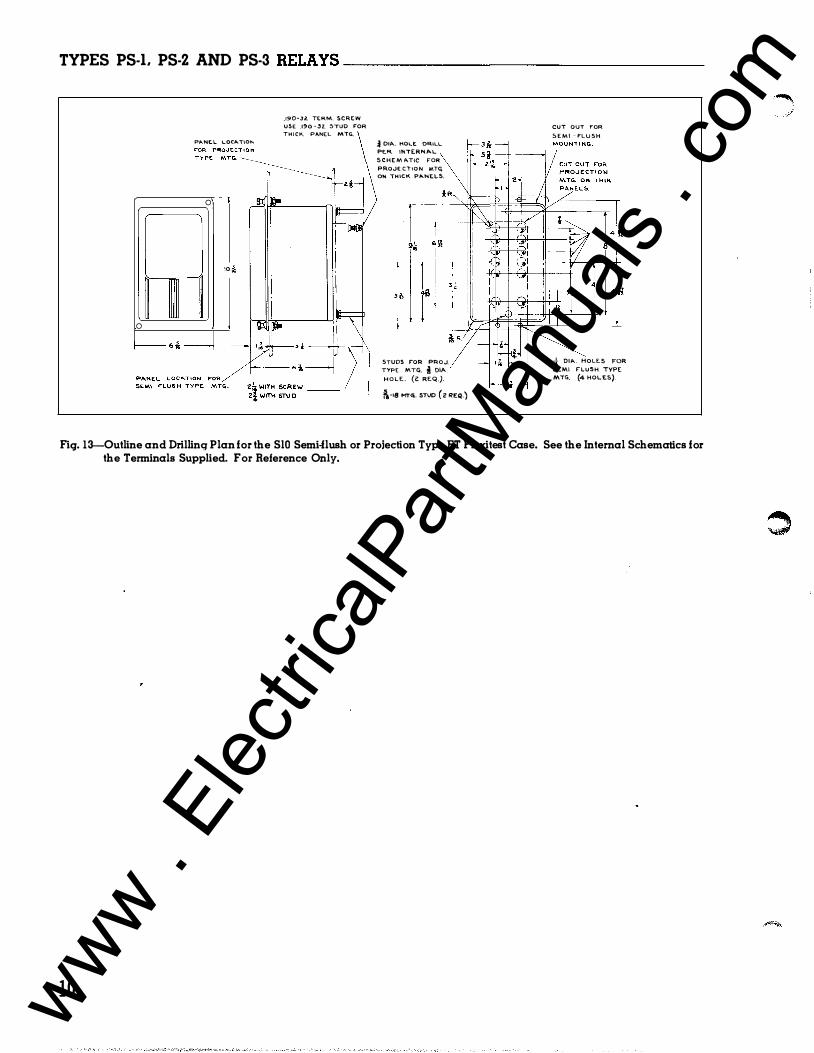
Fig. 13--0utline and Drilling Plan for the SlO Semi-flush or Projection Type FT Flexitest Case. See the Internal Schematics for the Terminals Supplied. For Reference Only.
10 www . El
ectric
alPar
tMan
uals
. com

www . El
ectric
alPar
tMan
uals
. com

W E S T I N G H O U S E E L E C T R I C C O R P O R A T I O N M E T E R D I V I S I O N • N E W A R K, N . J .
Printed in 1J .S.A. www . El
ectric
alPar
tMan
uals
. com
l .l. 41-659 F
INSTALLATION • OPERATION • MAINTENANC E
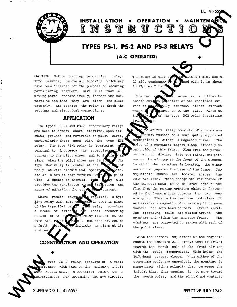
INS T R U C T I O N S TYPES PS-1, PS-2 AND PS-3 RELAYS
(A-C OPERATED)
CAUTION Before putting prot e ct ive rel ays
into service , remove all b locking which may
have been in serted for the purpose of securing
part s during shipment , make sure that all
moving part s operate freely, inspe ct the con
tacts to s e e that they are clean and close
properly, and operate the re lay to che ck the
settings and elect rical connect ions .
APPLICATION
The type s PS-1 and PS-2 supervisory rel ays
are used to dete ct short c ircuit s , open cir
cuit s , gro�nds and reve rsal s on pil ot wire s ,
part icularly those used with the type HCB
re lay . The type PS-1 re lay is located at one
terminal to :Jd)t roduge the supervisory d-e .
current to the p il ot wire s and to initiate an
alarm when the pilot wires are faulted . The
type PS-2 re lay is l oc ated at the other end of
the pilot wire circuit and operates to in it i
ate an alarm at that terminal when the pilot
wire is opened or shorted. This relay also
provide s the cont inuous visual indicat ion and
means of adjusting the supervisory current .
Where remote t ripping is required, a type
PS-3 relay with make contact s is used in place
of the type PS-2 rel ay . This relay provide s a mean s of t ripping the local breaker by action of an auxiliary rel ay l ocated at the
type PS-1 relay terminal , but doe s not act as
a fault detector to initiate an alarm at it s
stat ion .
CONSTRUCTION AND OPERATION
The type PS-1 relay consists of a small
t ransformer with taps on the primary, a full
wave Re ctox unit , a polarized re lay, and a
potent iometer for grounding the d-e circuit .
SUPERSEDES I.L 41 -659E
The rel ay is also suppl ied with a 4 mfd . and a
10 mfd . conden ser t o be used with it as shown
in Figure s 7 to 1 0 .
The two capacitors serve a s a filter t o
smooth out the pul sation o f the rectified cur
rent to pract ically constant dire ct current
which is introduced on to the pilot wires at
the mid-tap of the type HCB relay insulating
t ransforme r .
The polarized re lay con sist s o f an armature and contact mounted on a leaf spring supported symmetrically within a magnetic frame . The poles of a permanent magnet clamp directly to e ach s ide of this frame . Flux from the permanent magnet divides into two paths, one path across the air gap at the front of the e lement in which the armature is l ocated, the other across two gap s at the base of the frame . Two adjustable shunt s are located across the rear air gaps . These change the reluctance of the magnetic path so as to force some of the flux thru. the moving armature which is fasten
ed t o the frame midway between the two rear
air gap s . Flux in the armature polarizes it and creates a magnetic bias causing it to move towards the left -hand contact (front view ) . Two operating coils are p laced around the armature and within the magnetic frame . The windings are connected in serie s with each of
the pilot wire s .
With the corre ct adjustment o f the magnetic
shunt s the armature will always tend t o t rave l
t owards the north pole of the front air gap
with the coils deenergized . This holds the
left -hand contact closed . When e ither of the
operating coils are energized, the armature is
magnetized with a polarity that reverses the
init ial bias , thus causing it t o move t oward
the s outh pole s , and the right -hand contact .
EFFECTIVE JULY 1 949 www . El
ectric
alPar
tMan
uals
. com

TYPES PS-L PS-2 AND PS-3 RELAYS
TO MO'f' INGC.ONIACT
-- TO STATIONARY CONT"'CIS
____..- TES"T SWITCH
�--- TRANSFORMER WHEN NMMALLY ENEI(GIZED 6 Cl.l���TFLOWII'(� OtJT OF 1"i2MirtAL 10 -'ND l"i AT "TI!�MINAL 9 TE.NDS TO C.LOSE 1"1-!'E. I<'.H.(FRONT VI�W) C.O�TAC.TS
REAR V I E W
---- FULL WAVE RECT I F I E R
------- POLARIZE\) ELEMENT
�� �S� S�T� � qJ � -/ TO REL AY
l_Q_Q_J_6_6 __ 6_6_6_6 6 ------ TO BASE TERMS FRONT YIE.W
Fig. 1-Internal Schematic of the Type PS-I Relay in the Type FT Case.
Normally, the current through the re lay coils
i s of such a magnitude that the armature
float s midway bPtween the right and left
stat ionary contact s .
The type P S-2 re lay consists of a telephone
type re lay, a mil liammeter, an adjustable
re s istor, and two Re ctox unit s . The contact s
of the telephone rP lay are c losed at the de
energized posit ion . When the relay is ener
gized, the contact s stand open .
The type PS-3 re lay is ident ical to the type PS-2 except that the contact s are open in the
deenergizPd posit ion . This re lay does not
funct ion t o init iate an alarm when the pilot
wires are faulte d .
CHARACTERISTICS
The type PS-1 relay t ransformer has 100 ,
1 1 0 , 120 and 130 volt taps on the t ransforme r
primary . With tap voltage appliE,d to the
t ransformer primary, thP re lay will supply
.001 ampere d-e to the pilot wire at approxi
mat.Ply 17 vol t s d-e at the output terminal s .
Thi3 i s sufficient t o handle a 2000 ohm pilot
wire , and a type PS-2 or PS-3 re lay adjusted
f'or approximate ly 1 5 , 000 ohms internal re
si stan cP with . 00 1 amp . flowing. If n2ces sary
2
FULL WAVE -----., __ RECTIFIER ---t-->..t
/ REAR V I EW
WHEN NORMALLY ENERGIZED, CURRENT FLOWING OUT OF TERMINAL 10 AND IN AT TERMINAL 9 TENDS TO CLOSE THE R.H.(FRONT VIEW) CONTACTS.
Fig. 2-Internal Schematic of the Type PS-I Relay in the Standard Case.
as much as 130 volts may be used continuous ly
on any of the taps marked from 1 00 t o 130 .
The type PS-1, PS-2 and PS-3 re lays function
t o supervise the pilot -,.rire as follo�.r s :
( 1 ) . Normal Pilot Wire
The re lays are cont inuous ly energized vith
. 00 1 ampere d - e . which is introduced from an ext e rnal a - c . source thru the type PS-1 re lay
and circulates ove r the pilot ;.rire circuit .
Thi s current holds both the type PS-1 and
PS-2 re lay contact s open , and tends t o c lose
the type PS-3 re lay contact s .
( 2 ) . Pilot Wire Short Circuited
Short circuit s of' 2 , 000 ohms resistance or
le s s cause the circulat ing pilot wire cur
rent to increase above the normal value , thus
closing the right-hand ( f ront view) contacts
of the type PS-1 re lay and the undercurrent
contact s of the PS-2 relay to initiate an
alarm at both terminals of the pilot wire .
(3 ) . Pilot Wire Open Circuited
Open circuit s on the pilot wire wil l reduce
the circulating supervisory current to zero ,
and again initiate an alarm at both the type
PS-1 and PS-2 re lay terminal s .
www . El
ectric
alPar
tMan
uals
. com

TYPES PS-L PS-2 AND PS-3 RELAYS
J @ )( c
@)(
"TE5T :.'NITCH PS-z A./" ��- )( <D P> - 2 • II )(®
f;lE.AR VIEW TEST <>WITC� cp G!ltTO RELAY
0 6 rl, "TO BASE TI.Rt¥'15 FROWT VIEW
Fig. 3-lnternal Schematic of the Type PS-2 Relay in the Type FT Case.
( 4 ) . Pilot Wire Groundf"d
The conne ct ion of the separate windings of
the type PS-1 re l ay in each of the p i l ot wire
circuit s provide s two circuit s o f equal
impedan ce from the grounded midt ap of the
potentiomet P r in the typP PS-1 re l ay to the
remote t e rminal on the p i l ot wire . The type
P S-2 re lay contain s a re l at i w, ly high re
s i s t an c e , such that when P ither p i l ot wire
be come s grounded at any p o int al ong it s
length, unequal currf':nt s f l ow t o opf.lrate the
type" PS .. l re l ny . This provid e s sup,.,rvi s ion
for ground fcml t re s i s t an c e- valur-e 3 of 500 ohms
or l ( ·· s s ,
(5 ) . Re v0rs�d P i l ot W i r0 s
A rc-• ve: rsa l of t he- p i l ot v!i r, - s wi l l t · ·r: d t o
Ps : · re- lays in th'• r'• V rsc-d d i r•- ct iCJn .
CJr PS- ) Th� b�ctck
rt: l ays
l imit s
so that
of' th- R c t ox un its
i c "' u f f i c i·-- n t l .'T high :�nct , the- rr- f ore ,
the-: r.:u.tgn itudc, o f sup· r·-rL: ory curr'cnt
both thi'J t ypf-- PS-1 and PS :2 rr. l ays
opc·ratCJ on und�;; r currc,nt .
PS-j r�c l ay is u s "-d in plac'
".Vh•·r-, th"' typ<e
of the type PS-?
rtc lay, on ly th8 t yp,, PS- 1 r• l ay op�c ratr- s on
und'or curr:-:nt to ring ·.1n a l ':J.rr.J ,
l.l. 41 -659F
PS-'2. ®�------�;�r------�0 PS-2 0�------�J�r�------�
Rn:rox UNITS
RE:AR V/E:W
MILL/AHH£TC't;
TE:L£PHONC
TYPe ReLAY
Fig. 4-Internal Schematic of the Type PS-2 Relay in the Standard Case.
Remot e t ripp ing is ac compl i shed by app lying
an in c reas8d d-e voltage t o the p i l ot wire as
indi c at e d in FigurP s 8 and 1 0 . Whrm a 90 volt
s ource i s u s P d , such a s a "B" batt e ry , the two
re s i st ors shown in the diagram should be 1 1 00
ohms e ach to l imit the p i l ot vrire current t o
, 00 5 ampere , which i s suffi ciPnt t o operate
the PS�3 re l ay ad justed for . 00 1 5 or , 002
ampere p i ck up . On t hf• othf-'r han d , a 4 ') volt
bat t e ry s ource may be U S P d and the rP s i st ors
omitted, in which case th"' pilot wirr_. currf'-nt
will incrPasee to approximat r' ly . 004 ampere,
for thee rr,mot e t ripping op� r�ctt ion ,
RELAYS IN TYPE FT CASE
Tht-- typ� FT cas s r-;rr, dust -proof Pn c l o surc- s
conbinir.g ree L·1y •" l r ·nr, n t s and kn ifP -bh tde t e, s t
p rovid� s u c omp ,� ct
naintain , in spr- ct ,
tl!rH main un i t e;
This combin at ion
f l r xibl� as s Rmbly easy t o
t r s t and adjust , Th"' rR are
of t hP t yp ro FT cas"' : t hrcr
C ':L s r, , c ovr-r rctnd cha s s i s , The, case is an a l l
w-- l dr,d s t r- •- 1 hou s ing c or,t .'cJ.in ing th,, hing"' hal f
of th' lm ifr - b l adr t r-. st swit chr ·s and thcc
t ;-- rrninal s for , ,xt,c rn a l conw- c t i on s . The, c ove r
is a dravrn st" e- 1 frwne 1·1ith a c l r, ar window
which fit s ov�-- r thrr front o f the, cas": with the
swit chf': s c l o s •· d . The: cha s s i s i s a fram�" that
3 www . El
ectric
alPar
tMan
uals
. com
TYPES PS-1. PS-2 AND PS-3 RELAYS 1---------------
OPE.IC!AT\ON 1'-IDICATOR GOVER OPERATED ��----�S
I TEST
>WITCH WHEN USED
� I @ � 7r-l-3---l)�(@ 1 I I
I MILLIAM'-"ETE.2
RECTOX UNITS
�RED HANDLE TE.ST SWITCH
TO gELA.Y
FRONT VIE.W
Fig. 5-Internal Schematic of the Type PS-3 Relay in the Type FT Case.
houses the re lay element s and support s the
contact jaw half of the test switche s . This
s l ides in and out of the case . The elect rical
conne ct ion s between the base and chassis are
completed through the closed knife -blade s .
Removing Chas sis
To remove the chassis , first remove the
cover by un screwing the captive nut s at the
corners . There are two cover nut s on the S size case and four on the L and M size case s .
This exposes the re lay e lemen t s and all the test swit che s for inspe ction and testing . The next step is to open the test switche s .
Always op'm the elongated red handlR swit che s first before any of the black handle switches
or the cam action lat che s . This opens the
t rip circuit to prevent accidental t rip out .
Then open al l the remaining swit ches . The
order of opening the remaining swit ches is not
important . In opening the test switches they
should be moved all the ''ay back again s·t the
stops . With all the swit che s ful ly opened,
grasp the two cam action lat ch arms and pul l
outward . This releases the chas sis from the
case . Using the lat ch arms as handle s , pul l
the chassis out o f the case . The chassis can
be set on a test bench in a normal upright
posit ion as we l l as on it s t op , back or s ide s
for easy inspe ct ion , maintenance and test .
4
OPERATION INDICATOR ----,..--__.... PS-3
�--�---; � PS-3
>--------tl t-----®
HILLIAMM£TER
ReAR L;Jcw
TeLEPHONE Type ReLAY
Fig. 6-Internal Schematic of the Type PS-3 Relay in the Standard Case.
After · removing the chas sis a duplicate chassis may be inserted in the case or the
blade portion of the swit che s can be closed
and the cover put in place without
chas sis .
the
When the chassis is to be put back in the
case , the above procedure is t o be followed in
the reversed order . The elongated red handle
switch should not be closed until after the
chassis has been lat ched in place and all of the black handle swit che s c losed .
Elect rical Circuit s
Each terminal in the base conne ct s thru a
test switch t o the re lay element s in the
chassis as shown on the internal s chemati c
diagrams . The rel ay terminal is identified by
numbers marked on both the inside and out side
of the base . The test switch posit ions are
identified by letters marked on the top and
bottom surfac e of the moulded blocks . The s e
letters c an b e seen when the chassis is
removed from the case .
The pot ential and control circuit s thru the
relay are disconnected from the external cir
cuit by opening the associated test switche s .
www . El
ectric
alPar
tMan
uals
. com

TYPES PS-1, PS-2 AND PS-3 RELAYS ________________ I .L_4_1 -_65_9 F
TO {� TYPE t-\C.B
RELAY
116 1/ . €>0 c 'IC:. .
4 MFD
PILOT WIRE�
RECTOX U N I TS
PS -2
R EAR V IEW
T'IPE HC.B RELAY
TO }ALARM
C.IRCU\1'
Fig. 7-External Connections for the Types PS-1 and PS-2 Relays in the Type FT Case for Pilot Wire Supervision of a Two Terminal Line.
TO TYPE
HC.B RELAY
0+ 9Q>/.
0
DC BATTERY o-
PILOT WIRES
H---1--} TO ALARM C I RC. U \,.
RECTO X UNI\S
CONTACTS OF A U X I L I ARY RELAY FOR
1--------- REMOTE TR.I PPI NC, . WHEN USE D .
Cl
R E Ali: VIEW
TO TYPE HC B
RE.LIW
} TO TRIP Cl R.C. ITS
Fiq. 8-External Connections of the Types PS-1 and PS-3 Relays in the Type FT Case for Pilot Wire Supervision and Remote Trip of a Two Terminal Line.
5 www . El
ectric
alPar
tMan
uals
. com
TYPES PS-L PS-2 AND PS-3 RELAYS _______________ _
A cover operated switch can be suppl ied with
it s contact s wired in serie s with the t rip
circuit . This s'\dt ch opens the trip circuit
when the cover is removed • . This switch can be
added to the existing type FT case s at any
t ime .
Testing
The re lays can be te sted in service , in the
case but with the external circuit s isolated
or out of the case as follows :
Testing In Service
Voltage s between the potential circuit s can
be meusured convenient ly by clamping #2 c l ip
l eads on the projecting clip lead lug on the
contact jaw .
Testing In Case
With all blades in the ful l open position ,
the ten circuit test plug can be in serted in
the contact jaws . This connects the rel ay
e l ement s t o a set of binding posts and com
pletely is olates the relay circuits from the
external conne ctions by means of an insulat ing barrier on the plug . The external test cir
cuit s are conne cted to the se binding post s .
The plug is inserted in the bottom test jaws with the binding post s up and in the top test
switch jaws with the binding posts down .
The external test circuit s may be made t o
the re lay e lement s by # 2 t e s t clip leads
in stead of the test plug .
Testing Out of Case
With the chassis removed from the bas-e ,
relay element s may be t e sted by using the ten
circuit test plug or by #2 test c lip leads as
described above . The factory calibration is
made with the chassis in the case and removing
the chassis from the case wil l change the
calibration values by a smal l percentage . It
is recommended that the re lay be checked in
position as a final check on the calibration .
6
INSTALLATION
The relays should be mounted on swit chboard
pane l s or their equivalent in a location free
from dirt , moi sture , exce s sive vibrat ion and
heat . Mount the re lay vert ically by means of
the two mounting studs for the standard cases
and the type FT project ion case or by means of
the four mounting hol e s on the flange for the
semi-flush type FT case . Either of the studs
or the ·mounting s c rews may be ut il ized for
grounding the re lay . The electrical con
nect ions may be made direct to the terminals
by means of screws for steel panel mount ing or
to terminal studs furnished with the relay for
ebony-asbe stos or s late panel mounting . The
terminal studs may be
inserted by locking two
easily removed or
nut s on the s tuds and
then turning the prope r nut with a wrench .
The external connections for the type s PS-1
and PS-2 relays are shown in Figure s 7 or 9 ,
and for the type PS-1 and PS-3 in Figure s 8 or
1 0 . For information concerning the type HCB
re lay see I . L . 4 1 -658 .
CAUTION The se relays are connected dire .::tly
in the pilot wire circuit and must be pro
t e cted against high potential re sultin g from
induction or difference s in ground potential
between the pilot wire terminal s .
SETTINGS
The re lays are calibrated in the fact ory t o
b e energized continuou s ly with one mil liampe re
d-e . After the re lays are checked and
instal led, the only setting required is t o
select the proper voltage tap in the type PS-1
relay and to adjust the s l ide wire re sistance
in the type PS-2 or PS-3 rel ay, so that the
mil liammeter in the relay indicates that one
mil liampere d-e . is circulat ing over the pilot
wire s . If difficulty is expe rien ced in
getting . 001 ampere d-e supervisory current
in the pilot wire , sele ct the next lower or
higher voltage tap in the PS-1 rel ay, as may
be required .
www . El
ectric
alPar
tMan
uals
. com
f
TYPES PS-1. PS-2 AND PS-3 RELAYS _______________ u_. _41_-6s_9F
1 1 5 "· 100 CYC.
PI LOT �IRES
I N SUL�TI NG TR�NSFORMER
} T�PE .....____ HCB RELAY
PS-2. TO ALARM
Joo--1'-���...IRCUIT
Fig. 9-External Connections of the Types PS-1 and PS-2 Relays in the Standard Case for Pilot Wire Supervision of a Three Terminal Line.
INSULATING TR�NSFORMER
TO { "NPE
HCB RELAY
I ISV. 60 CVC.
PILOT WIRES
4 Mfll.
CONT,.,CTS Of "UX. RELAY !=OR REMOTE TRIPPING,WI-IEN U5ED
INSUUTING TRANSF.:}ORM�:
1'YPE HCB REL"Y
TO TRI P CIRCUITS
Fig. 10-External Connections of the Types PS-1 and PS-3 Relays in the Standard Case for Pilot Wire Supervision and
Remote Trip of a Two Terminal Line.
7 www . El
ectric
alPar
tMan
uals
. com

TYPES PS-L PS-2 AND PS-3 RELAYS -----------------
1-4---- F
F1<:t . 3
�-- F
MTq, \iOI..eS F'Oii? . I " 0 O I A
5CIZEW
MTC:, . HOLES FOR . 1�0 DIA.
I< E W
. ...: 0 \ M E N S \ O N S v r-�--��r--r--��--�� u. A B C O E F G H
I �
Fig. 1 1-0utline and Drilling Plan for the Auxiliary 4 and 10 Mfd. Capacitors. For Reference Only.
8
Due t o a relatively wise variation in re ctox
forward re sistance characteristics it is
neces sary to provide an ext ra terminal on the
t ransformer secondary coil in the PS-1 relay
for purposes of adjustment . In the event that
. 00 1 ampere d-e supervisory current c an not be
obtained by the combined adjustment s of the
s l ide wire res istance in the type PS-2 or PS-3
re lay and the use of the primary voltage taps
in the PS-1 relay then the conne ction t o the
t ran sformer se condary coil in the PS-1 relay
must be changed . In such cases , remove the
lead from the center t e rminal on the secondary
coil and conne ct it to the extra terminal , which is the t op terminal on the coil . This
connect ion wil l raise the voltage output of
the PS-1 re lay so that the current may be ad
justed to . 001 amp . by means of the s l ide wire
resistan ce in the PS-2 or PS-3 relay .
NOTE : Add tap t o all PS-1 s chematics .
If pilot wires are subject t o induct ion from
adjacent t ran smission line s , it is recommended
that the relays be set in the l aboratory
rather than while they are direct ly conne cted
to the pilot wire s . This precaution is to
p revent in jury to the personnel from high
induced voltage s . Neutralizing t ran sformers
are available for use t o keep high voltage s
from the relay .
ADJUSTMENTS AND MAINTENANCE
The proper adjustment s to insure corre ct
operation of this re lay have been made at the
fact ory and should not be disturbed afte r
receipt by the custome r . If the adjustment s
have been changed, the re lay t aken apart for
repairs , or if it is de sired to che ck the
adjustment s at regular maintenan ce periods ,
the in struct ions bel ow should be foll owed .
All cont act s should be periodically cleaned
with a fine file . Style #10021 1 0 file is
re commended for thi s purpose . The use of
abrasive material for cleaning contact s is not
re commended, be cause of the danger of
embedding smal l particles in the face of the
soft silve r and thus impairing the contact .
www . El
ectric
alPar
tMan
uals
. com
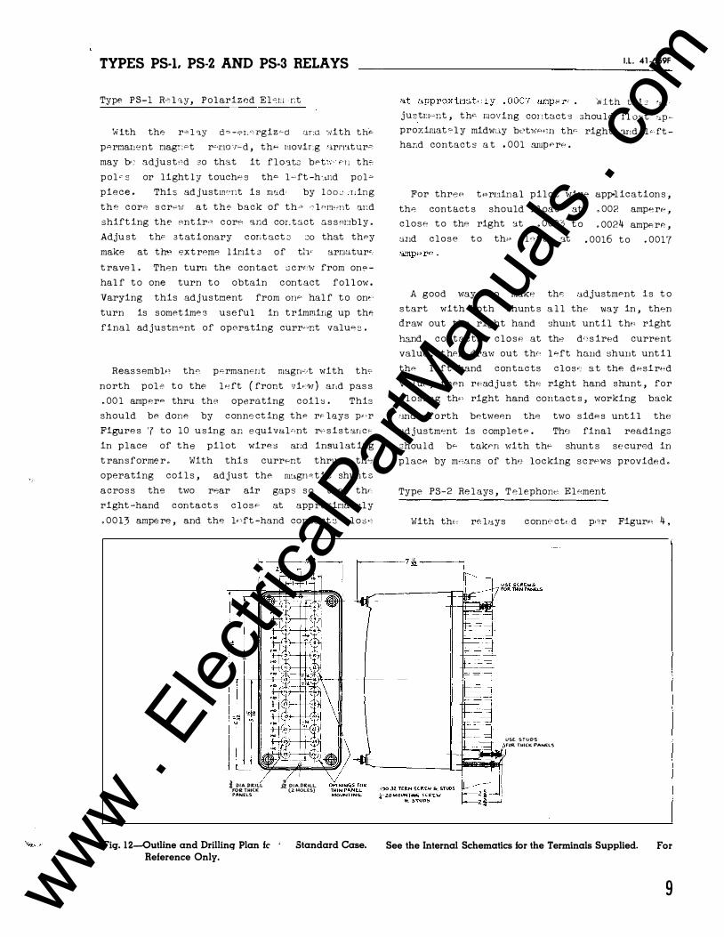
TYPES PS-1. PS-2 AND PS-3 RELAYS
Type PS-1 R"> l "lY, Polarized Elctl r,t
',Jith the r� l ·:J.Y ct� -"'L"o rgiz �ct ar:a ·:�ith thF"
p<=>rmar1ent nagc>"t r'·rw ·r�d , the; rnovir.g 'lrn•J.tUr"
may be; adjust:;d so that it f l o-at;::: bet\;- f' l l th�
p o l e s or light ly touche s th<> l � ft -h·"'r;d pol"'
piece . Thi s ad justm';r;t is mad• by l o o c: r :ing
the c orP s crew at th"- back of th� -• l mnc;nt -:wd
shift ing the Pnt ir-" c ore and cor. t::;.ct o.s s P.r:rbly .
Adju st the s t at i onary c ont o.ct 2 JO that they
make at the ext reme l ir1it s of tl·F arr:mtur"
t rave l . Th8n turn thA contact s c r':W from one
hal f t o one turn t o obtain c ont act fol l ow .
Varying this ad justment from OJJF' hal f t o on�·
turn is somet iml" s useful in t rimming up the
final ad justm<>nt of operating curr,�nt valu<C 3 .
Reas s embl<C the permanent magn"·t with th''
north pole t o the l R ft ( front vi,c·�1 ) ar,d pas s
. 00 1 amper<> thru the operating coil � . This
should be done by c onne ct ing thP r" lays w-r
Figure s '7 to 10 u s ing an e quival>"nt r•' s i s t ar, c<c
in p lace of the p i l ot wire s ar:d insu l at ing
t ran s forme r . With thi s current thru th�
operating coi l s , ad just the rn:,gn P t i c shunt s
acro s s the two rFOar air gap s s o that thrc
right -hand c ontact s c l o s e at app roxir.w.t , l y
. 00 13 ampe re , and the l•'ft -hand contact e1 c l o s "?
1.- D/A.J)ItiLL FOR THICK PANELS
Fiq. 1 2-0utline and Drillinq Plan fc Reference Only.
3� 0/A. DRILL (Z·HOLES)
Standard Case.
I.L. 41 -659F
'liith thL 'J.d justr:t- 'nt , th•- moving cor:tuct s should fl o :tt .'.tP proximat P l y midwLJ.y bt't'HF·<:n th'' right ar :d l • · ft
har.d contact s a t , 001 anJW ' rP .
For threP tPre:tinal pilot wirP app-l ication s ,
thA cont act s should f l oat at . 002 ampe re ,
c l o s e t o the right �t . 002) t o
cmd c l o s e t o thP 1 <�ft .at
• 0024 ampe rF� ,
• 0016 t o • 0017
A good way to make th<S adjustmPnt is t o
s tart with both Ghunt s a l l the way in , thPn
draw out th•J right hand 3hunt unt il thf' right
h3.nd c ontacts c l a s P at thA d': s ired current
value , t hPn draw out thr: l"eft hand �hunt unt i l
thP le-;ft hand contacts c l o s e: a t the dPsirPd
value , thPn readjust the right hand shunt , for
c l o s ing th,, right hand contact s , working back
-'J.nd forth bPtwe<?n the two s idA s unt i l the
.o-J.d justm<ont is c omplete . Th<J final readings
:chou l d bP taken with the shunt s se cured in
place by m'"ans of th•; locking s c rews provide d .
Type PS-2 Re l ays , T e l ephon;o, Elc�ment
With tht-: r"' lays c onne ct<. d pc>r Figur"' 4 ,
USE STUDS fOR THICK PANELS
See the Internal Schematics for the Terminals Supplied. For
9 www . El
ectric
alPar
tMan
uals
. com

TYPES PS-L PS-2 AND PS-3 RELAYS _______________ _
adjust the armature gap and spring tension of
the telephone -type re lay so that it s contact s
open with . 0008 ampere and above and close at
approximately . 0006 ampere and be low o The
normal contact gap should be approx - 1/32 inch
and should have a contact fol low of approxi
mate ly 1/64 inch.
Type PS-3 Rel ay, Te lephone Element
With the relays connected per Figure 8 or
10 adjust the armature gap and the spring ten
s ion of the telephone relay s o that its con
tacts close at , 0015 or , 002 ampere and above .
PA.Nt.L LOC.O.T\0._,
�-----..::0
. 190-JZ. TERM. SCREW USE .1�0 - 32. STUD FOR THICK PANEL MTG.
z'! Wm< STUD
RENEWAL PARTS
at
Repai r \wrk can be
the fact ory o done most satisfactorily
Hm;ever , interchangeable
part s can be furni shed to the customers who
aro equipped for doing repair worko When
orde ring part s , always give the c omplete name
plat e dat a .
ENERGY REQUIREMENTS
The 60 cycle burden of the type PS-1 re lay
i s approximate ly O o 5 volt ampe re at tap
voltage with . 001 ampere d-e flowing over the
pilot wire .
::f DIA.. HOLE DRILL PE.R. INTE.RN ,C...L SCHEMATIC FOR PR.O.JE.CTlON MTG. ON. THICK p,e..,NE.LS.
STUDS F"OR PRO,.J, TYPE MT�. i DIA . HOLE (� REQ.). �-18 Ml"<!j. STUD ( 2 RtQ.)
CUT OUT f"OR 5EMI - FLUSH
* DIA. HOLES FOR SEMI FLU S H TYPE MTG. (4 HOU:.S).
Fiq. 13-0utline and Drilling Plan for the SIO Semi-flush or Projection Type FT Flexitest Case. See the Internal Schematics for the Terminals Supplied. For Reference Only.
10 www . El
ectric
alPar
tMan
uals
. com

www . El
ectric
alPar
tMan
uals
. com

W E S T I N G H O U S E E L E C T R I C C O R P O R A T I O N M E T E R D I V I S I O N e N E W A R K, N . J .
Printed in 1J .S.A. www . El
ectric
alPar
tMan
uals
. com

l.l. 41-659 H
INSTALLATION • OPERATION • MAINTENANCE
INSTR U CT IO N S TYPES PS-1, PS-2 AND PS-3 RELAYS
(A-C OPERATED)
CAUTION Before putt ing prot e ct ive rel ays
into ser-..; J.ce , remove all blocking which may
have been in sert6d for the purpose of securing
part s during shipment , make sure that all
moving part s ope rate freely, inspect the con
t act s to see that they are clean and c lose
p roperly, and ope rate the rel ay to che ck the
settings and e l e ct rical connect ion s .
APPLICATION
The typ e s PS-1 and PS-2 supervisory rel ays
are used to det e ct short circuit s , open cir
cuit s , gro�nds and reve rsals on pilot wire s ,
part icularly those used with the type HCB
re lay . The type PS-1 re lay is located at one
t e rminal to introduce the supervisory d-e .
current t o the pilot wires and t o initiate an
alarm when the pilot wires are faulted . The
type PS-2 relay is located at the other end of
the pilot wire circuit and operate s t o initi
ate an alarm at that terminal when the pilot
wire is opened or shorted . This rel ay als o
provides the continuous visual indication and
means of adjusting the supervisory current .
Where remote t ripping is required, a type PS-3 re lay with make contacts is used in place
of the type PS-2 rel ay . This re lay provide s a mean s of t ripping the local breaker by
action of an auxiliary relay l ocated at the
type PS-1 re lay terminal , but doe s not act as
a fault detector to init iate an alarm at its
stat ion .
CONSTRUCTION AND OPERATION
The type PS-1 re lay c on sist s of a small
t ran sformer with tap s on
secondary windings , a ful l
a polarized rel ay, and a
grounding the d-e circuit .
SUPERSEDES l.l. 41 -659 G
the primary, and wave Re ctox unit ,
potent iometer for
The re lay i s also
supplied with a 4 mfd . and a 10 mt·d . condenser
t o be used with it as shown in Figure s 7 to
10 .
The two capacitors serve as a filter t o
smooth out the pul sat ion of the re ctified cur
rent to practically constant direct current
whi ch is int roduced on to the pilot wire s at
the mid-tap of the type HCB relay insulating
t ransformer .
The polarized rel ay consist s o f an armature and contact mounted on a leaf spring supported
symmet rically within a magnet ic frame . The
poles of a permanent magnet clamp directly t o
each s ide o f this frame . Flux from the perma
nent magnet divides int o two paths , one path
across the air gap at the front of the e lement
in which the armature is l ocated, the other
acro s s two gap s at the base of the frame . Two
adjustable screw type shunt s are located in
the rear air gaps . The se change the reluc -
t ance of the magnet-ic path so as to force some
of the flux thru the moving armature which i s
fastened t o the frame midway between the two
rear air gap s . Flux in the armatute po larize s it and create s a magnetic bias causing it t o
move t oward s the left -hand contact ( front
view ) . Two operating coi l s are p laced around
the armature and within the magnetic frame .
The windings are connected in serie s with e ach
of the pilot wire s .
With the correct adjustment of the magnet i c
shunt s the armature wil l always tend t o t ravel
t owards the north pole of the front air gap
with the coi l s deenergized . This holds the
left -hand contact closed . When e ither of the
operating coils are energized, the armature i s
magnetized with a polarity that reverses the
initial bias , thus causing it to move t oward
the s outh pole s , and the right -hand contact .
EFFECTIVE JUNE 1 951 www . El
ectric
alPar
tMan
uals
. com

TYPES PS-1. PS-2 AND PS-3 RELAYS----------------
TO I"'' OVINGC.ONTACT
����:i�t6���� E0't,;-��EO 6 TEI!Mli'III.LIO ,I>,NI) 114 AT i't!�MINAL 9 TENDS TO C.LOS.E TI-lE fV4.(J="�ONT 'l'leW)COI<>lTAC.TS.
REAR VIEW
FRON"T '/IE.W
- TO STATIONARY CONTAC"'TS
------ TEST SWITCK
TRANSl="ORME.R
F\JLL WAVE
RECTIFIER
PO\...A.RIZE.t> ELEMENT
Fig. 1-lnternal Schematic of the Type PS-I Relay in the Type FT Case.
Normally, the current through the re lay coil s
is of such a magnitude that the armature
float s midway between the right and left
stat ionary c ontact s .
The type PS-2 re l ay consist s of a t elephone
type rel ay, a mil l iammeter, an adjustable
resistor, and two Rectox unit s . The contacts
of the t e lephone re lay are c losed at the de
energized posit ion . When the re lay is ener
gize d , the contact s stand open .
The type PS-3 rel ay is identi cal t o the type PS-2 except that the contact s are open in the
deenergized posit ion . This rel ay does not
function t o init iate an alarm when the pilot
wire s are faulted .
CHARACTERISTICS
The type PS-1 re lay t ransformer has 100 ,
110 , 120 and 130 volt tap s on the t ransformer
primary . With tap voltage applied t o the
t ransformer primary, the relay will supply
. 00 1 ampere d-e t o the pilot wire at approxi
mateely 17 vol t s d-e at the output terminals .
This is sufficient t o handle a 2000 ohm pilot
wire , and a type PS-2 or PS-3 relay adjusted
for approximate ly 1 5 , 000 ohms internal re
s ista.nc8 with . 00 1 amp " flowing . If nP-ce s s ary
2
FULL WAVE ----.--RECTif"IER --+-->./
REAR VIEW
WHEN NORMALLY ENERGIZED, CURRENT FLOWING OUT OF TERMINAL 10 AND IN 1\T TERMINAL 9 TENDS TO CLOSE THE R.H.(FRONT VI EW) CONTACTS.
POLARIZED ELEMENT
Fig. 2-Internal Schematic of the Type PS-I Relay in the Standard Case.
as much as 130 vol t s may be used continuously
on any of the t ap s marked from 1 00 t o 130 .
The secondary winding al so has a t ap , the
use of which i s de scribed under " Setting s " .
The type PS-1 , PS-2 and PS-3 re lays function
t o supervise the pilot wire as foll ow s :
( 1 ) . Normal Pilot Wire
The re lays are cont inuou s ly energized •rith
. 001 ampere d-e . which is introduced from an external a - c . source thru the type PS-1 relay
and circulat e s ove r the pilot ,.,ire c ircuit .
This current holds both the type PS-1 and PS-2 re lay contact s open , and t ends t o c lose
the type PS-3 re lay contact s .
(2 ) . Pilot Wire Short C ircuited
Short c ircuits of 2 , 000 ohms res istance or
l e s s cause the c irculating pilot wire cur
rent to increase above the normal value , thus
closing the right -hand (front view ) contacts
of the type PS-1 rel ay and the undercurrent
contact s of the PS-2 relay to init iate an
alarm at both terminals of the pilot wire .
(3 ) . Pilot Wire Open Circuited
Open circuit s on the pilot wire wil l reduce
the circulat ing supervisory current t o zero ,
and again initiate an alarm at both the type
PS-1 and PS-2 re lay terminal s .
..
www . El
ectric
alPar
tMan
uals
. com

TYPES PS-1. PS-2 AND PS-3 RELAYS
TES.l !)VII\TC"' J PS·Z A.;V
@ )( II" )( <D c P>·Z 8
@ )( II )(®
Fig. 3-Internal Schematic of the Type PS·2 Relay in the Type FT Case.
( 4 ) . Pilot Wire Grounded
The connection of the separate windings of
the type PS-1 relay in each of the pilot wire
circuit s provides two circuit s of e qual
impedan ce from the grounded midtap of the
potent iometer in the type PS-1 relay to the
remote terminal on the pilot wire . The type
PS-2 re lay contains a relat ive ly high re
sistan ce , such that when e ither pilot wire
becomes grounded at any point along its
length, unequal current s flow t o operate the
type PS-1 relay . This p rovide s supervision
for ground fault re sistance value s of 500 ohms
or lP s s .
( 5 ) . Reversed Pilot Wire s
A reve rsal of the pilot wires will te�d t o
pass currc.,nt t hru the typr-c PS�2 o r PS-3
rF:lays in thA rev1.;rsed dir� ct ion . The back
resistan cs of the Re ctox unit s in thPSe
relays is sufficiPntly high and , thRrefore, ,
l imit s the magnitudA of supervisory current
so that both the type PS-1 and PS-·2 relays
operate on under current . Where the type
PS-j re lay is used in plac� of the type PS-2
re lay, only the type PS'-1 rel ay op8rates on
under current to ring an alarm."
Rt:C70X UNITS
REAFI VIEW
I.L. 41 -659 H
MILLIAHH£T£k
TELEPHONE
TYPe ReLAY
Fig. 4-Internal Schematic of the Type PS-2 Relay in the Standard Case.
Remote t ripping is accomplished by applying
an increased d-e voltage to the pilot wire as
indicated in Figure s 8 and 10 . When a 90 volt
s ource is used, such as a "B" battery, the two
resistors shown in the diagram should be 1 1 00
ohms each t o limit the pilot wire current t o
. 005 ampere , which is sufficient t o operate
the PS-3 relay adjusted for . 0015 or . 002
ampere pick up . On the other hand , a 45 volt
battery s ource may be used and the resistors
omitted, in which case the pilot wire current
will increase to approximately . 004 ampere
for the remote tripping operat ion .
RELAYS IN TYPE FT CASE
The type FT cas e s are
combining relay elements
dust -proof enclosures
and knife-blade test swit che s in t he same case . This combination providPs a compact flexible assembly easy t o
maintain , inspe ct , t e s t and adjust . Tl1ere are
three main un it s of the type FT case : the
case , cover and chass i s . The case is an all
welded steel housing containing the hinge half
of thP lcnife -blad8 t8st swit che s and the
terminals for exte rnal conne ctions . The cover
is a dravm steel frame ��ith a c lear window
which fit s over the front of the cas8 with the
swit che s closPd . The chassis is a frame that
3 www . El
ectric
alPar
tMan
uals
. com
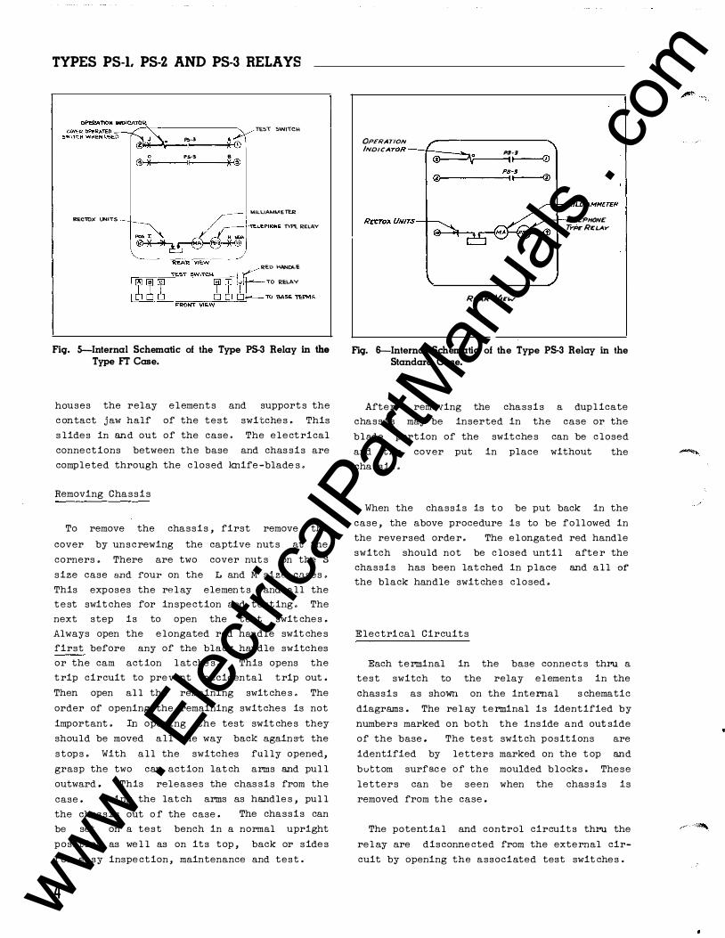
TYPES PS-I. PS-2 AND PS-3 RELAYS
RECTOX UNITS
P.;-3 I
PS·'!o II
8 )(@
TES\ 5WITCH
MILLIAM\AETER
TELE.PI-\ONE 1'Yf'E RELAY
RED HANDLE
TO 2£LAY
Fiq. 5--Internal Schematic of the Type PS-3 Relay in the Type FT Case.
houses the relay element s and support s the
c ontact jaw half of the test switche s . This
s lides in and out of the case . The elect rical
connections between the base and chas sis are
completed through the c losed knife -blade s .
Removing Chassis
To remove the chassis , first remove the
cover by uns c rewing the captive nut s at the
corners . There are two cover nut s on the S
size case and rour on the L and M size cases .
This exposes the rel ay elemen t s and all the
t e st swit ches for inspection and testing . The
next step is to open the test swit che s .
Always open the e longated red handle swit che s
first before any of the black handle switches
or the cam act ion l at che s . This opens the
t rip circuit to prevent accidental t rip out .
Then open al l the remaining swit che s . The
order of opening the remaining switches is not
important . In opening the test swit che s they
should be moved all the way back agains·t the
stops . With a l l the switches ful ly opened,
grasp the two cam action lat ch arms and pul l
outward . This releases the chas sis from the
case . Using the lat ch arms as handle s , pul l
the chas sis out o f the case . The chassis can
be set on a test bench in a normal upright
posit ion as we l l as on its top , back or side s
for easy inspe ction , maintenance and test .
4
OPERATION INDICA TOR---t---•· . P8·9 �--���----��
MILLIAMMETER
ReAR !new
TcLt:PHONC TYPCRCLAY
Fiq. 6-Internal Schematic of the Type PS-3 Relay in the Standard Case.
After · removing the chassis a duplicate
chassis may be inserted in the case or the
blade portion of the switche s can be c losed
and the cover put in place without
chassis .
the
When the chassis is t o be put back in the
case , the above procedure is to be followed in
the reversed orde r . The e l ongated red handle
switch should not be c losed until afte r the
chassis has been lat ched in place and a l l or the black handle swit che s closed .
Electrical Circuits
Each terminal in the base connect s thru a
test switch to the relay element s in the
chassis as shown on the internal s chematic
diagrams . The rel ay terminal is identified by
numbers marked on both the inside and out side
of the base . The test swit ch positions are
identified by letters marked on the t op and
buttom surfac e of the moulded blocks . These
letters can be seen when the chass is is
removed from the case .
The potent ial and control circuit s thru the
rel ay are disconne cted from the external cir
cuit by opening the associated test swit che s .
www . El
ectric
alPar
tMan
uals
. com

TYPES PS-1. PS-2 AND PS-3 RELAYS _______________ L_L . _"',_-65_9 H
TO {=:1 TYPE
HC5 RELAY
115 v 60 C'IC .
PILOT WIRE5
1 A��RM >---+-+-- f C. I R C. Ul T >--++--.-'
PS-2
T 'I PE t-IC.B RELAY
TO }AL-ARM
C:..IRCUrT
R EC TOX .!--+------:-?, \J N I TS
R EAR VIEW
4 MFD
Fiq. 7-External Connections for the Types PS-1 and PS-2 Relays in the Type FT Case for Pilot Wire Supervision of a Two Terminal Line.
TO T'f'PE
HC6 RE.LAY
I I:I V.
0 &0 C'ICLES
0+ 90\f. DC
BA'T'TERY o-
PILOT '1NIRES
r-t--f--�} TO ALP<RM C I RC. U \0
Ret:TOX --1-...-J--. UNI\5
C.ONTACIS OF A U X I L I ARY REI... AV !=OR REMOTE TRI PPIN<?, , WHEN U'&ED . �------------------------
CJ
R E A R VIEW
TO TYPE HCS
RE.L,_Y
} TO TRIP CIRC. ITS
__ _j
Fiq. 8-External Connections of the Types PS-1 and PS-3 Relays in the Type FT Case for Pilot Wire Supervision and Remote Trip of a Two Terminal Line.
5 www . El
ectric
alPar
tMan
uals
. com
TYPES PS-I. PS-2 AND PS-3 RELAYS -----------------
A cover operated switch can be suppl ied with
its contact s wired in serie s with the t rip
circuit . This switch opens the t rip circuit
when the cover is remove d . This switch can be
added to the existing type FT case s at any
t ime .
Testing
The relays can be te sted in service , in the
case but with the external circuit s is olated
or out of the case as fol l ows :
Testing In Service
Voltage s between the potential circuits can
be measured conveniently by clamping #2 c l ip
leads on the proje cting clip lead lug on the
contact jaw .
Testing In Case
With all blade s in the ful l open posit ion ,
the ten circuit t e st plug can be inserted in
the contact jaws . This connects the rel ay
element s to a set of binding pos t s and com
pletely isolat e s the re lay circuit s from the
external connections by means of an insulat ing
barrier on the plug . The external test cir
cuit s are conne cted to the se binding post s .
The plug is inserted in the bottom test jaws
1-rith the binding post s up and in the top t e s t
switch j aws with the binding p o s t s down .
The external test circuit s may be made to
the re lay element s by #2 test clip leads
in stead of the test plug .
Testing Out of Case
With the chassis removed from t he ,bas e ,
relay element s may be te sted b y using the t en
circuit test plug or by #2 test clip leads as
described above . The factory calibration is
made with the chas sis in the case and removing
the chassis from the case wil l change the
calibration values by a small percentage . It
is recommended that the re lay be checked in
position as a final check on the calibration .
6
INSTALLATION
The relays should be mounted on swit chboard
panels or their equivalent in a l o cat ion free
from dirt , moisture , exce s sive vibration and
heat . Mount the re lay vert ically by means of
the two mounting studs for the standard cases
and the type FT pro j e ct ion case or by means of
the four mounting hol e s on the flange for the
semi-flush type FT case . Either of the studs
or the ·mounting screws may be util ized for
grounding the re lay. The electrical con
nect ions may be made direct to the terminals
by mean s of screws for steel panel mount ing or
to terminal studs furnished with the relay for
ebony-asbe stos or s late panel mountin g . The
terminal studs may be easily removed or
inserted by l ocking two nut s on the studs and
then turning the proper nut with a wrench.
The external connection s for the type s PS-1
and PS-2 rel ays are shown in Figure s 7 or 9 , and for the type PS-1 and PS-3 in Figure s 8 or
1 0 . For information concerning the t ype
relay see I . L . 4 1 -658 .
HCB
CAUTION The se relays are connected dire .::tly
in the pilot wire circuit and must be pro
t e cted against high potent.ial resulting from
induction or differences in ground potential
between the p il ot wire terminal s .
SETTINGS
The rel ays are calibrated in the fact ory to
be energized continuously with one milliampere
d-e . Afte r the re lays are checked and
installed, the only setting required is t o
select the proper voltage tap in the type PS-1
re lay and to adjust the s lide wire resistance
in the type PS-2 or PS-3 rel ay, so that the
mil liammeter in the rel ay indi cat e s that one
milliampere d-e . is circulating over the pilot
wire s . If difficulty is experienced in
get t ing . 001 ampere d-e supervisory current
in the pilot wire , select the next l ower or
higher voltage tap in the PS-1 rel ay, as may
be r.,quire d .
www . El
ectric
alPar
tMan
uals
. com
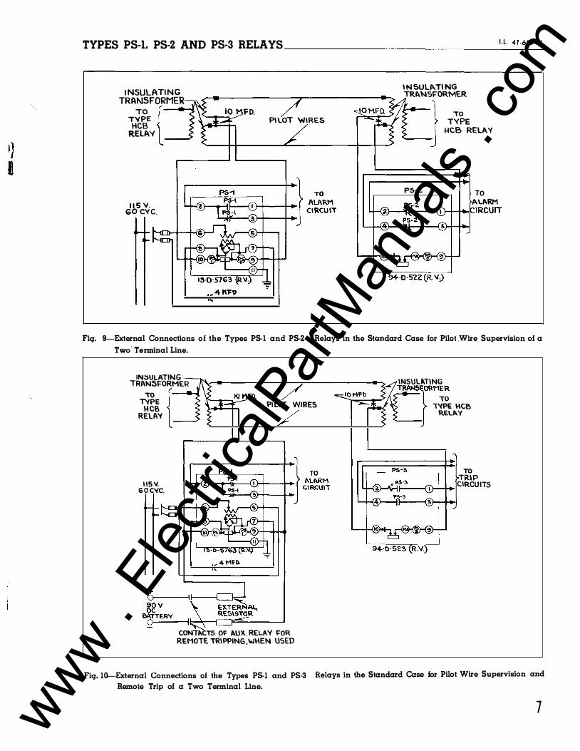
TYPES PS-1. PS-2 AND PS-3 RELAYS _______________ 1_· L_4_1 - 6_s9_H
I NSULATI N G TRANSFORMER
TO { TYPE
HCB RELAY
1 1 5 "· 100 eve.
F D. PI LOT 'WIRES
I N SUL�TI NG TR�NSI="ORMER
l T��E "----J �CB RELAY
PS-2. TO A\_/>.RM
��----� ��-�tRCUIT
Fiq. 9-External Connections of the Types PS-1 and PS-2 Relays in the Standard Case for Pilot .Wire Supervision of a
Two Terminal Line.
IN5ULATING TRANSFORMER
TO { TYPE
H CB RELAY
1 15 \1. ro o eve.
PILOT WIRES
4 MFO.
CONTto.CTS OF />.UX. RELAY FOR REMOTE TRIPPING ,WHEN USED
1"0
INSUUT\NG TRANSFJORMER
IVPE HCB REL"Y
TO TRIP CIRCUIIS
Fiq. 10--External Connections of the Types PS-1 and PS-3 Relays in the Standard Case for Pilot Wire Supervision and
Remote Trip of a Two Terminal Line.
7 www . El
ectric
alPar
tMan
uals
. com
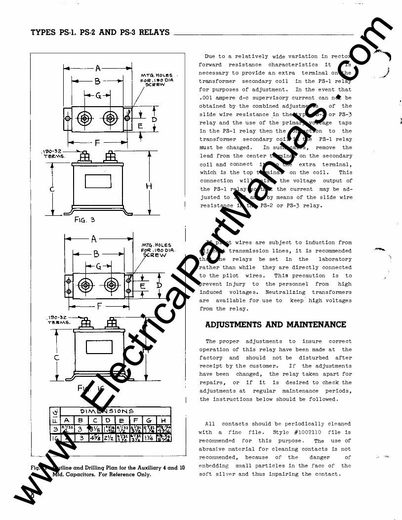
TYPES PS-1. PS-2 AND PS-3 RELAYS _______________ _
�-- F
FIG . 3
MTGr. l101..eS FOR . \ !t O OIA
5C ii! EW
MT4 . HOLES FOR . \'?10 0\A.
R E W
L--------------------------------------�
Fig. 1 1-0utline and Drilling Plan for the Auxiliary 4 and 10 Mfd. Capacitors. For Reference Only.
8
Due t o a rel at ively wide variation in re ctox
forward resistance characteristics it is
neces sary t o provide an extra terminal on the
t ransformer secondary coil in the PS-1 relay
for purposes of adjustment . In the event that
. 00 1 ampe re d-e supervisory current can n ot be
obtained by the combined adjustments of the
s l ide wire re sistance _in the type PS-2 or PS-3
relay and the use of the primary voltage taps
in the PS-1 rel ay then the connection to the
t ransformer secondary coil in the PS-1 rel ay
must be changed . In such case s , remove the
lead from the center t e rminal on the secondary
coil and c onne ct it to the extra terminal ,
which is the t op terminal on the coil . This
c onnection wil l raise the voltage output of
the PS-1 relay s o that the current may be ad
justed to . 00 1 amp . by means of the s l ide wire
re s istance in the PS-2 or PS-3 rel ay .
If pilot wires are subj e ct t o induct ion from
adj acent transmi s sion l ine s , it is recommended
that the relays be set in the l aboratory
rather than while they are dire ct ly connected
to the pilot wire s . This precaution is t o
prevent in jury to the personnel from high
induced voltage s . Neutralizing t ransformers
are available for use to keep'
high voltage s
from the rel ay .
ADJUSTMENTS AND MAINTENANCE
The proper adjustment s t o insure c orre ct
operation of this relay have been made at the
factory and should not be disturbed after
receipt by the custome r . I f the adjustmen t s
have been changed , the re lay t aken apart for
repairs , or if it is desired to che ck the
adjustment s at regular maintenance periods ,
the instruct ions be low should be fol l owed .
All contact s should bP periodical ly cleanPd
with a f ine file . Style #1002110 file is
recommendPd for this purpose . The use of
abrasive material for c leaning contacts is not
re commended, because of the danger of
embedding small part icles in the face of the
soft silver and thus impairing the contact .
www . El
ectric
alPar
tMan
uals
. com
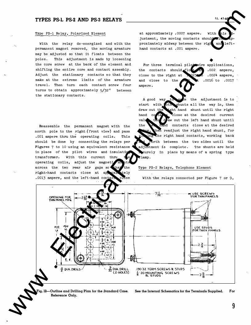
TYPES .PS-1. PS-2 AND PS-3 RELAYS
Type PS-1 Re lay , Polarized Element
With the relay de -energized and with the permanent magnet removed, the moving armature
may be adjusted so that it float s between the
pole s . This adjustment i s made by loo sening
the c ore screw at the back of the e l ement an d
shift ing the ent ire c ore and contact a s semb ly .
Adjust the stat ionary cont acts s o that they
make at the ext reme limit s of the armature
t rave 1 . Then turn each ·contact screw four
turns to obtain approximat e ly 5/32 "
t he stat ionary c ontact s . between
Reas semble the permanent magnet with the
north pole to the right ( front view ) and pass
. 00 1 ampere thru the operating coil s . Thi s
should be done by connecting the relays per
Figures 7 to 1 0 using an equivalent re sistance
in place of the pilot wire s and insulat ing
t ransforme r . With this current thru the
operating coil s , adjust the magnetic shunt s
acro s s the two rear air gaps so that the
right-hand contact s close at approximate ly
. 0013 ampere , and the left -hand contact s close
I.L. 4 1 -659 H
at approximate ly . 0007 ampere . With this ad-
justment , the moving contact s should float ap
proximately midway between the right and left
hand contact s at . 00 1 ampere .
For three terminal pilot wire appl icat ions ,
the cont act s should fl oat at . 002 ampere ,
c lose to the right at . 0023 t o . 0024 ampere ,
and close t o the left at . 0016 t o . 0017
ampe re .
A good way t o make the adjustment is t o
start with both shunt s a l l the way in , then
draw out the right hand shunt unt il the right
hand contact s close at the de sired current
value , then draw out the left hand shunt unt i l
the left hand contact s c l o s e a t the des ired
value , then readjust the right hand shunt , for
closing the right hand contact s , working back
and forth between the two s ide s unt il the
adjustment is c omplete . 'l'he shunt s are he ld
secure ly in place by mean s of a spring t ype
c lamp .
Type PS-2 Re lay s , Telephone Element
With the relays c onne cted per Figure 7 or 9 ,
-------� USE SC.Iit E: W !> FOR THIN PANELS
-r--- - --- - ---- - ----
Fig. 12-0utline and Drilling Plan for the Standard Case. Reference Only.
. 1�0-32 TERM SCR[WS � STU DS -41 - zo MOUNTING SCREWS &:. STUDS
See the Internal Schematics for the Terminals Supplied. For
9 www . El
ectric
alPar
tMan
uals
. com

TYPES PS-1. PS-2 AND PS-3 RELAYS _______________ _
adjust the armature gap and spring tension of
the t e lephone -type relay so that it s contact s
open with . 0008 ampere and above and close at
approximate ly . 0006 ampere and bel ow . The
normal contact gap should be approx . 1/32 inch
and should have a contact fol low of approxi
mate ly 1/64 inch.
Type PS-3 Relay, Te lephone Element
With the relays connected per Figure 8 or
10 adjust the armature gap and the spring ten
sion of the t e lephone relay so that its c on
t act s c l o s e at . 0015 or . 002 ampere and above .
. 190-32. TERM. SCREW
UH .190 -3Z. STUD FOR
THICK PANEL MIG.
RENEWAL PARTS
Repair work can be done most satisfact orily
at the fact ory . Howeve r, interchangeable
part s can be furnished to the customers who
aro equipped for doing repair work. When
ordering part s , always give the c omp lete name
plat e dat a .
ENERGY REQUIREMENTS
The 60 cycle burden of the type PS-1 re lay
is approximately 0 . 5 volt ampere at t ap
voltage with . 001 ampere d-e flowing over the
pilot wire •
CUT OUT f"OR
&EM I - FLUSH PANC.L. LOCA.T\Oh f:'"OR, f>RO.JECTlON TYPE
.J D I A. . HOLE. DRILL
PE.R. lttT(.RNA.L
SC HEMATIC FOR
PROJECTION MTG. ON THICK P.-..NE\...5.
0
! 0 1
0
� 6 � -STUD$ F"OR PROJ,
TYPE. MTG. ! OIA. HOLL (� REQ.).
�-18 MTIO. STUD ( 2 REQ.)
i DIA. HOLES FOR
SE.MI F"LUSH TYPE
MTG. (4 HOLE.S).
Fig. 13-0utline and Drilling Plan for the SID Semi-flush or Projection Type FT Flexitest Case. See the Internal Schematics for the Terminals Supplied. For Reference Only.
1 0 www . El
ectric
alPar
tMan
uals
. com

..
www . El
ectric
alPar
tMan
uals
. com

W E S T I N G H O U S E E L E C T R I C C O R P O R A T I O N M E T E R D I V I S I O N e N E WA R K, N . J .
Printed in U.S.A. www . El
ectric
alPar
tMan
uals
. com