c. marshall space flight center mttrshall space flight ... · which are greater than that provided...
TRANSCRIPT

NASA TECHNICAL
MEMORANDUM
NASA TM X-73394
ORBIT TRANSFER SYSTEMS WITH EMPHASI S ON SHUTTLE APPLICATIONS -1986-1991
By Program Development
April 1977
NASA
George C. Marshall Space Flight Center Mttrshall Space Flight Center, Alabama
https://ntrs.nasa.gov/search.jsp?R=19770019254 2018-06-10T15:46:09+00:00Z

4
TECHNICAL REPORT STANDARD TITLE PAGE 3. RECIPIENT'S CATALOG NO. 1. REPGRT NO. 2. GOVERNMENT ACCESSION NO.
NASA TM X-73394 TITLE AND SUBTITLE 5. REPORT DATE
April 1977Orbit Transfer Systems with Emphasis on Shuttle 6. PERFORMING ORGANIZATION CODE
Applications - 1986-1991
8. PERFORMING ORGANIZATION REPORr 11',7, AUTHOR(S)
9, PERFORMING ORGANIZATION NAME AND ADDRESS 10. WORK UNI~ NO.
George C. Marshall Space Flight Center 11. CONTRACT OR GRANT NO.
Marshall Space Flight Center, Alabama 35812
~~~~~~~~~~~~~~~~~~~~~~~~~~~~~~~~~13. TYPE OF REPOR~ a PERIOD COVERED 12, SPONSORING AGENCY NAME AND ADDRESS
Technical Memorandum ; National Aeronautics and Space Administration
Washington, D. C. 20546
~5. SUPPLEMENTARY NOTES
'" Prepared by Program Development
16, ABSTRACT
The problems of orbit transportation have been addressed significantly during the past 5 years. An Interim Upper Stage (IUS) and a Spinning Solid Upper Stage (SSUS) are being developed for operation in the, early 19RO's. Current long-range planning efforts indicate a need for extended space operations capabilities which are greater than that provided by IUS and SSllS.
This is a systems study for a transportation system which will follow the IUS and SSUS. Included are concepts, concept comparisons, trends, parametric data, etc. associated with the future system. Helevant technical and programmatic information is developed. This information is intended to focus future activity to identify attractive options and to summarize the major issues associated with the future development of the system. A comprehensive summary of the study is included in the body of the report in section X VI.
It is primarily the developing need for Earth synchronous orbit capabilities which gives cause for further consideration of orbital transportation systems at this time. Transportation needs for manned and unmanned synchronous orbit systems are foreseen. Total recoverability and reusability with minimum refurbishment are goals for future orbit transport systems.
To establish a common basis for identifying current transportation concepts, an Orbit Transfer Vehicle (OTV) is defined as a propulsive (velocity producing) rocket or stage. When used with a crew transfer module, a manned sortie module or other payloads, the combination becomes an Orbit Transfer
~ System (OTS). Standardization of OTV's and OTS's is required.
17. KE'r WORDS 18. DISTRIBUTION STATEMENT
Unclassified - Unlimited
19, SECURITY CLASSIF. (of thla report\ 20. SECURITY CLASSI F. (of this page) 21. NO. OF PAGES 22, PRICE
Unclassified Unclassified 218 NTIS
MSFC - (.'orm 3292 (Rev December 1912) For sale by National Technicallnforrrtation Sl'rvice, S~ringfield, Virginia 22 t S1

TABLE OF CONTENTS
Page
I • BACKGROUND ••••••••••••••••••••••••••••••••• 1
• II. INTRODUCTION •••••••••••••••••••••••••••••••• 2
• III • SIGNIFICANT EARLY FINDINGS ••••••••••••••••••••• 4
IV. ORBIT TRANSFER TRANSPORTATION REQUIREMENTS •••• 6
V. OTV CONCEPTS (CONFIGURATIONS) ••••••••••••••••• 15
A. Lox/Hydrogen Propellant Concepts • • • • • • • • • • • • • • • • 15 B. Space Storable Propellant Concepts • • • • • • • • • • • • • • • • 21 C. Convertible Cargo/Man Module. • • • • • • • • • • • • • • • • • • 22 D. Emergency Return Vehicle Configurations ••••••••••• 23 E • Orbit-Based Service Vehicles. • • • • • • • • • • • • • • • • • • • 25 F. Manned Sortie Mission Hardware ••••••••••••••••• 27 G. Docking (Loading/Unloading) Module Configuration. • • • • 28 H. Unique Designs to Obtain Shorter Stages. • • • • • • • • • • • • 31 I. 100 000 lb Capability Shuttle/AMOOS Cargo Bay
Configurations • . • . • • • • . • • • • • • • • • • • • • • • • • • • • • 33 J. Unmanned Payload Configurations. • • • • • • • • • • • • • • • • 36
VI. ~~I(}I11L DJ\1LA •••••••••••••••••••••••••••••••• 37
A. Lox/Hydrogen Propellant Stages • • • • • • • • • • • • • • • • • • 37 B. Lox/Hydrogen Propellant Drop Tanks •••••••••••••• 37 C. Earth and Space Storable Propellant Stages. • • • • • • • • • • 48 D. Manned Modules and Emergency Vehicles. • • • • • • • • • • • 48 E. Manned Sortie Mission Weights ••••••••••• '. • • • • • • • 61 F. OTV Propellant Loading - Propellant Weight Required. • • 65
I VII. OTV FLIGHT PROFILES •••••••••••••••••••••••••• 67
A. Events and Issues •••••••••••••••••••••••••••• 70 B. Single Stage APOTV •••••••••••••••••••••••••• 72 C. Single Stage AMOOS •••••••••••••••••••••••••• 72 D. Emergency Vehicle. • • • • • • • • • • • • • • • • • • • • • • • • • • 75 E. Two-Stage Application. • • • • • • • • • • • • • • • • • • • • • • • • 75
iii

TABLE OF CONTENTS (Continued)
Page
VIII. OTV PERFORMANCE/CAPABILITIES '0 •••••••••••••••• 75
A. OTV Single Stage Capabilities •••••••••••••••••••• 76 •B. Staging Effects on OTV Capab'iUty - One Shuttle
Launch. • • • • • • • • • • • • • • • • • • • • • • • • • • • • • • • • • • 76 C. Capability Comparison for One- and Two-Shuttle
Lallnchcs ••••••••••••••••••••••••••••••••• 76 D. Expendable Solid BoosterH for I\Tultiple Shuttle
Launchcs ••••••••••••••••••••••••••••••••• 81 E. Engine I Effects for Lox/Ilydrogen Cases •••••••••• 81
sp F. Payload Partial Sensitivity for OTV Using Lox/Hydrogen
for Geosynchronous Orbit Missions. • • • • • • • • • • • • • • • 81 G. Oxidizer - Fuel Mbd:urc Ratio Considerations for OTV •• 86
IX. SHUTTLE CARGO BAY LENGTH CONSIDERATIONS ••••••• 88
A. Single Shuttle Launch OTV - Lox/Hydrogen Propellants. • 88
X. CHEMICAL ENGINE SYSTEMS FOR OTS ••••••••••••••• 93
A. Cryogenic Propellant Systems ••••••••••••••••••• 93 B. Storable Propellant Systems. • • • • • • • • • • • • • • • • • • • • 96 C. Solid Rocket lVTotors • • • • • • • • • • • • • • • • • • • • • • • • • • 98D. Summary................................ 98
XI. MISSION MODEL CAPTURE FOn 65 000 AND 100 000 lb SHUTTLE CAPABILITIES. • • • • • • • • • • • • • • • • • • • • • • • • 98
A. 65 000 lb Shuttle Capability Comparison. • • • • • • • • • • • • 99 B. 100 000 Ib Shuttle Capability Comparison • • • • • • • • • • • • 99 C. Annual Launch Rate Comparison. • • • • • • • • • • • • • • • • • 108
XII. PROGRAM SCHEDULES AND COSTS •••••••••••••••••• 108
A. Schedules (For APOTV/ AMOOS Comparison) ••••••••• 110 B. Engine Development •••••••••••••••••••••••••• 110 C. Schedule Compari son ••••••••••••••••••••••••• 113 D. Program Costing (Comparison) •••••••••••••••••• 113 E. Schedules and Cost for Planning Usage •••••••••••••• 121
iv
• • • • • • • • • •
• • • • • • • • • • • • • • • • • • • • • • • • • • • • • • • • • • • • • • • •
• • • • • • • • • • • • • • • • • • • • • • •
TABLE OF CONTENTS (Continued)
Page
XITI. APOTV-AMOOS DESIGN COMPARISONS ••• • • • • • • • • • • • • 124 •
A. Detailed Layout - Design Comparison •• • • • • • • • • • • • • 125 B. Propulsion •••••••••• • • • • • • • • • • • • • • • • • • • • • • 125
• C. Structures ••••••••••••••••• • • • • • • • • • • • • • • • • 125 D. Thennal/Thennal Control • • • • • • • • • • • • • • • • • • • • • • 126 E. Guidance, Navigation, and Control •••••••••••••••• 126 F. Communication and Data Management •••••••••••••• 127 G. Perfonnance/Capability Comparison. • • • • • • • • • • • • • • 127
XIV. DISCUSSION OF THE OTV PROGRAM OPTIONS 130
A. Lox/Hydrogen Propellant Orbit Transfer Vehicles • • • • • • 130 B. Space/Earth Storable Propellant OTV •••••••••••••• 135
XV. TECHNOLOGY REQUIREMENTS. • • • • • • • • • • • • • • • • • • • • 135
Ao Aerodynamic/Aerothermal •• 135 B. Ablative Heat Shield •••••• 136 C. Subsystem Hardware •••••••••••••••••••••••••• 136 D. Pumping of Liquids in Space. • • • • • • • • • • • • • • • • • ••• 138 E. Summary Technology Requirements •••••••••••••••• 138
XVI. SUMMARY ••••• • • • • .. • • • • • • • • • • • • • • • • • • • • • • • • 139
A. Background •• • • • • • • • • .. • • • • • • • • • • • • • • • • • • • • 139 B. Introduction. • • • • • • • 0 139 C. Study Approach ••••••••••••••••••••••••••••• 139 D. Significant Early Findings •••••••••••••••••••••• 140 E. Orbit Transfer Transportation Requirements ••••••••• 140 F • OTV Configurations/Concepts •••••••••••••••••••• 141
• G. Weight Data •••••••••••••••••••••••••••••••• 141 H. OTV Flight Profiles •••••••••••••••••••••••••• 146 I. OTV Perfonnance Capabilities ••••••••••••••••••• 146 J. Shuttle Cargo Bay Length Issues •••••••••••••••••• 149 K. Mission Model Capture •••••••••••••••••••••••• 150 'L. Program Costs and Schedules •••••••••••••••••••• 151 M. APOTV/ AMOOS Design Comparison ••••••••••••••• 151 N. Comparison of the Options •••••••••••••••••••••• 151 O. Teohnology Requirements •••••••••••••••••••••• 155 P. OTV Program Options •••••••••••••••••••••••• 155 Q. OTV Activity Status/FUture ••••••••••••••••••••• 160
v

TABLE OF CONTENTS (Concluded)
Page
XVII. RECOMMENDATIONS. • • • • • • • • • • • • • • • • • • • • • • • • • • • 160 •
APPENDIX A - A SUMMARY OF THE DEVELOPMENT STATUS OF CHEMICAL ENGINE SYSTEMS UNDER GONSIDERA •TION FOR THE ORBITAL TRANSFER SYSTEM (OTS) (NOVEMBER 1976) ••••••••••••••••••• 163
APPENDIX B - SUPPORTING STUDY DATA NOT COVERED BY THE NARRATIVE. • • • • • • • • • • • • • • • • • • • • • • 171
APPENDIX C - OTV - MSFC STUDY PARTICIPANTS. • • • • • • • • • • • 203
'" t•
vi

LlSTOF ILLUSTRATIONS
Figure Title Page
1 • study beginning and early findings • • • • • • • • • • • • • • • • • • • 5
• 2. Baseline APOTV configuration ••••••••••••••••••••• 16
3. APOTV - 50 200 lb propellant for 65 000 lb Shuttle ••••••• 16
4. APOTV - 95 000 lb propellant for 125 000 lb Shuttle •••••• 17
5. APOTV length versus propellant loading ••••••••••••••• 17
6. Baseline AMOOS configuration ••••••••••••••••••••• 18
7. AMOOS - 48 500 lb propellant for 65 000 lb Shuttle capability • • • • • • • • • • • • • • • • • • • • • • • • • • • • • • • • • • • 19
8. AMOOS length versus propellant loading ••••••••••••••• 20
9. AMOOS - 90 200 lb propellant ••••••••••••••••••••• 20
10. APOTV lox/RP and N20 4/MMH ••••••••••••••••••••• 21
11. AMOOS lox/RP and N20 4/MMH ••••••••••••••••••••• 22
12. . Convertible cargo/man module ••••••••••••••••••••• 22
13. Emergency return vehicle - Apollo concept •••••••••••• 23
14. Aeromaneuvering Reentry System ••••••••••••••••••• 24
15• Aeromaneuvering Reentry System (crew and cargo accommodations) • • • • • • • • • • • • • • • • • • • • • • • • • • • • • • 24
•
• 16. Aeromaneuvering Reentry System (convertible cargo/man module berth) •••••••••••••••••••••••••••••••• 25
17. Service vehicle (a derivative of the AMRS lifeboat) ••••••• 26
18. Service vehicle (a derivative of the convertible cargo/crew module) •••••••••••••••••••••••••••••••••••• 26
vii

•••
••••••••••
LI ST OF ILLUSTRATIONS (Continued)
Figure Title Page
19. Service vehicle (a derivative of the AMRS module berth) 27
• 20. Manned sortie configuration (convertible cargo/crew
module) •••••••••••••••••••••••••••••••••••• 28 •
21. Docking (loading/unloading) module ••••••••••••••••• 29
22. Docking/positioning AMRS/module berth •••••••••••••• 29
23. Docking/positioning/module transfer ••••••••••••••••• 30
24. Module transfer/placement ••••••••••••••••••••••• 30
25. End-view - docking system ••••••••••••••••••••••• 31
26. AMOOS design for cargo bay length restraints ••••••••••• 32
27. Single Shuttle/AMOOS (100 000 lb Shuttle payload capability) •••••••••••••••••••••••••••••••••• 34
28. Typical AMOOS flight configurations •••••• 0 35
29. Unmanned orbital platform •••••••••••••••••••••••• 36
30. Lox/hydrogen propellant APOTV weight versus propellant loading. • • • • • • • • • • • • • • • • • • • • • • • • • • • • • • • • • • • • 41
31. Lox/hydrogen propellant AMOOS weight versus propellant. loading. • • • • • • • • • • • • • • • • • • • • • • • • • • • • • • • • • • • • 45
32. Lox/hydrogen propellant drop tank weight versus propellant loading ••••••••••••••••••••••••••••••••••••• 47 ..
33. Lox/RP propellant APOTV weight versus propellant loading. • • • • • • • • • • • • • • • • • • • • • • • • • • • • • • • • • • • • 53
34. N20 4/MMH propellant APOTV weight versus propellant loading. • • • • • • • • • • • • • • • • • • • • • • • • • • • • • • • • • • • • 54
viii

Ll ST OF ILLUSTRATIONS (Continued)
Figure
35.
36• •
37.
38.
39.
40.
41.
42.
43.
44.
45.
46.
47.
.48. •
49.
Title Page
Lox/RP propellant AMOOS weight versus propellant loading ••••••••••••••.•.•••••••••.•••••••••• 59
N20,/MMH propellant AMOOS weight versus propellant loading .•••••••••••••••••••••••••••••••••••• 60
Crew module weight versus man days • • • • • • • • • • • • • • • • 62
Four-man sortie mission module (reference crew transfer module) weight and volume requirement ••••••••••••••• 66
Stage weights verl;lUS Shuttle capability •••••••••••••••• 68
OTV propellant loading propellant weight required •••••• 69
APOT V flight profile. • • • • • • • • • • • • • • • • • • • • • • • • ••• 73
AMOOS flight profile •••••••••••••••••••••••••••• 74
Single stage OTV performance comparison ••••••••••••• 77
Single stage OTV performance/capabilities ••••••••••••• 78
Staging effects for OTV systems (100 000 Ib Shuttle capability) • • • • • • • • • • • • • • • • • • • • • • • • • • • • • • • • • • 79
Single/dual Shuttle performance/capabilities •••••••••••• 80
Solid boosters for large payloads geosynchronous capability • • • • • • • • • • • • • • • • . • • • • • • • • • • • • • • • • • • 82
I effects on the geosynchronous orbit APOTV payload sp
capability • • • • • • • • • • • • • • • • • • • • • • • • • • • • • • • • • • • 83
I effects on the geosynchronous orbit AMOOS payloadsp
capability • • • • • • . • • • • • • • • • • • • • • • • • • • • • • • • • • • • 84
•••••••
LI ST OF ILLUSTRATIONS (Continued)
Figure Title
50. OTV payload capability - sensitivity to burnout weight (65 000 lb Shuttle) .. . . . . .. . . . . . . . . ... . . .... . . ..
51- Oxidizer - fuel mixture ratio considerations for OTV AMOOS with lox/hydrogen - 65 000 lb Shuttle capability ••••
52. APOTV-AMOOS cargo bay requirements comparison (lox/hydrogen at 470 sec I ) ••••••••••••••••••••••
sp
53. OTV length issues (lox/hydrogen) •••••••••••••••••••
54. Unique design to meet cargo bay length restraint •••••••••
55. OTV with improved Shuttle (60 ft cargo bay) ••••••••••••
56. Engine configurations •••••••••••••••••••••••••••
57. Total program capture/launches required ••••••••••••••
58. Advanced engine comparison schedule ••••••••••••••••
59. APOTV comparison schedule ••••••••••••••••••••••
60. AMOTV comparison schedule ••••••••••••••••••••••
61. AMOTV comparison schedule (option) ••••••••••••••••
62. OTV program (comparison) nonrecurring cost summary ... 63. OTV program cost summary (comparison) including
Shuttle transportation •••••••••••••••••••••••••••
64. OTV program cost (discounted at 10 percent) summary (comparison) including Shuttle transportation" •••••••••••
65. OTV planning schedules (APOTV and AMOTV), •• 0
Page
85 ., 87 •
89
91
92
94
97
109
111
112
114
115
119 ., 119
120
122

LI ST OF ILLUSTRATIONS (Concluded)
•
•
Figure
66.
67.
68.
69.
70.
71.·
72.
73.
74.
75.
76.
77.
·.. 78 •
•
Title Page
OTV nonrecurring cost summary ••••••••••••••••••• 123
Geosynchronous orbit capability comparison •••••••••••• 128
Four-man Sortie capability requirement (Shuttle/OTV capability referenced) • • • • • • • • • • • • • • • • • • • • • • • • • • • 129
OTV geosynchronous delivery capability (lox/hydrogen) -payload required •••••••••••••••••••••••••••••• 131
OTV geosynchronous round trip capability (lox/hydrogen) -payload required •••••••••••••••••••••••••••••• 132
Capability comparison lox/hydrogen OTV • • • • • • • • • • • • • • 133
Orbit transfer systems-concepts. • • • • • • • • • • • • • • • • • • • 142
All propulsive orbital transfer vehicle weights (APOTV) ••• 143
Aeromaneuvering orbit to orbit stage weights (AMOOS) •••• 144
Weights for manned systems •••••••••••••••••••••• 145
.All propulsive orbit transfer vehicle geosynchronous orbit typical configurations and flight profile ••••••••••••••• 147
Aeromaneuvering orbit transfer vehicle geosynchronous orbit typical configurations and flight profile. • • • • • • • • • • • 148
STS cost summary (1976 dollars) ••••••••••••••••••• 152
xi

• • • • • • • • • • • • • • • • • • • • • • • • • • • • • • • • •
LI ST OF TABLES
Table Title Page
1. Geosynchronous Orbit - Four-Man station •••••••••••••• 8
• 2. Geosynchronous Orbit - Four-Man Station •••••••••••••• 9
3. Derived Crew Transfer and Four-Man Sortie Capability • Requirements 10
4. Miscellaneous Candidate Payloads for OTV •••••••••••••• 12
5. Nominal Program Option Candidate Missions - OTV ••••••• 13
6. Low Program Option Candidate Missions - OTV •••••••••• 14
7. APOTV Baseline Weights •••••••••••••••••••••••••• 38
8. APOTV Weights for 83 255 lb Propellant Load •••••••••••• 39
9. APOTV Weights for 99 248 Ib Propellant Load •••••••••••• 40
10. Baseline AMOOS weights •••••••••••••••••••••••••• ' 42
11. AMOOS Weights for 72 000 lb Propellant Load •••••••••••• 43
12. AMOOS Weights for 90 200 lb Propellant Load •••••••••••• 44
13. Drop Tank Weights •••••••••••••••••••••••••••••• 46
14. APOTV with 52 394 lb Lox/RP1 Propellant Load •••••••••• 49
15. APOTV with 99 865 lb Lox/RP1 Propellant Load •••••••••• 50 ~.. 16. APOTV with 56 595 lb N20 4/MMH Propellant Load ••••••••• 51
• 5217. APOTV with 99 865 lb N204/MMH Propellant Load •••••••••
5518. AMOOS with 52 391 lb Lox/RP1 Propellant Load ••••••••••
5619. AMOOS with 99 911lb Lox/RP1 Propellant Load ••••••••••
LI ST OF TABLES (Continued)
Table Title Page
20. AMOOS with 52 412 lb NaO,/MMH Propellant Load. • • • • • • • • 57 •
21. AMOOS with 99 865lb Na04/MMH Propellant Load ••••••••• 58
• 22. Weight Summary - Manned Carriers (Weight in lb) •••••••• 61
23. Transportation/Sortie Mission Manned Volume Requirements ••••••••••••••••••••••••••••••••• 63
24. Transportation/Sortie Mission Manned Module Weight Requirements ••••••••••••••••••••••••••••••••• 64
25. Weights Required for Crew Transfer and Sortie Missions •••• 65
26. Sequence of Events for APOTV Flight Profile • • • • • • • • • • • • 73
27. Sequence of Events for AMOOS Flight Profile • • • • • • • • • • • • 74
28. Geosynchronous Payload Partial Sensitivity ••••••••••••• 86
29. Nominal Program Option, 65 000 lb Shuttle/APOTV • • • • • • • • 100
30. Nominal Program Option, 65 000 lb Shuttle/AMOOS • • • • • • • • 101
31. Low Program Option, 65 000 Ib Shuttle/APOTV • • • • • • • • • • • 102
32. Low Program Option, 65 000 lb Shuttle/AMOOS. • • • • • • • • • • 103
33. Nominal Program, 100 000 lb Shuttle/APOTV • • • • • • • • • • • • . 104
34. Nominal Program, .100 000 lb Shuttle/AMOOS • • • • • • • • • • • • 105
• 35. Low Program Option, 100 000 lb Shuttle/APOTV •••••••••• 106
36. Low Program Option, 100 000 lb Shuttle/AMOOS •••••••••• 107
37. OTV Cost Summary (1976 Dollars in Millions) ••••••••••• 118
xiii
• • • • • • • • • • •
LI ST OF TABLES (Concluded)
Table Title
38. OTV Technology Requi rements ••••••••••••••••••••••
39. APOTV/AMOOS Design Comparison (General)
40. APOTV/AMOOS Design Comparison (Subsystems) •••••••••
41. OTV/STS Evolution - Current Shuttle (Using APOTV Concept - GEO Missions) •••••••••••••••••••••••••
42. OTV/STS Evolution - Improved Shuttle (Using APOTV Concept - GEO Missions) •••••••••••••••••••••••••
43. OTV/STS Evolution - Current Shuttle (Using AMOOS Concept - GEO Missions) •••••••••••••••••••••••••
44. OTV/STS Evolution - Current Shuttle Leading to Improved Shuttle (Using AMOOS Concept - GEO Missions) • • • • • • • • •
45. OTV Activity Status/Future ••••••••••••••••••••••••
Page
138
• 153
154 •
156
157
158
159
161

•
•
•
TECHNICAL MEMORANDUM X-73394
ORBIT TRANSFER SYSTEMS WITH EMPHASIS ON SHUTTLE APPLICATIONS -1986-1991
I. BACKGROUND
The problems of orbit transportation have been addressed significantly during the past 5 years. Early efforts defined a Space Tug which used high energy cryogenic propellants, and considerable technology development effort has occurred on this type transportation element. Primarily due to programmatic considerations, the cryogenic Space Tug concept was replaced by the Interim Upper Stage (IUS) and Spinning Solid Upper Stage (SSUS) which use solid motor propulsion. These systems are being developed and will be available in the early 1980's for use as an upper stage with the Space Shuttle.
In the meantime many new space initiatives have been conceived by the National Aeronautics and Space Administration (NASA). Considerable longrange planning, which is now underway, will lead to the need for extended space operations capabilities which are greater than that provided by IUS and SSUS. While firm plans for development of the space resources have not been completed at this time, the general trend for development after low Earth orbit seems to be toward development of the synchronous Earth orbit resource first, then toward returning to and development of the lunar resources and further exploration and development of the resources of the other planets. The lunar and planetary developments receive very little consideration, and the nature and timing of their development will be largely dependent on what eventually takes place in the development of the Earth orbit capabilities. It is primarily the developing need for Earth synchronous orbit capabilities which gives cause for further consideration of orbital transportation systems at this time.
The Earth synchronous orbit transportation capability with current United States rocket technology is not an easy one to achieve. Total recoverability and reuseability with minimum refurbishment are goals for future orbit transport systems. Previous study efforts and Space Shuttle developments have led to these goals primarily on an economic basis. Accommodation of the goals requires return of the rocket elements, certain payload carrier elements, and sometimes the rocket payload.
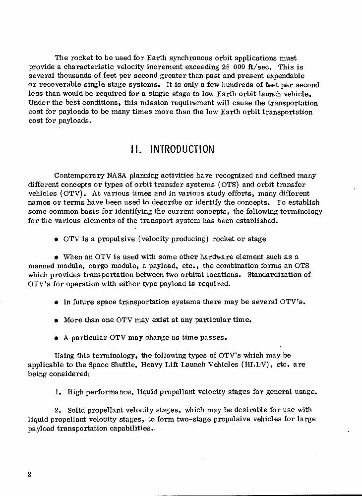
The rocket to be used for Earth synchronous orbit applications must provide a characteristic velocity increment exceeding 28 000 ft/sec. This is several thousands of feet per second greater than past and present expendable or recoverable single stage systems. It is only a few hundreds of feet per second less than would be required for a single stage to low Earth orbit launch vehicle. Under the best conditions, this mission requirement will cause the transportation cost for payloads to be many times more than the low Earth orbit transportation .. cost for payloads.
• II. INTRODUCTION
contemporary NASA planning activities have recognized and defined many different concepts or types of orbit transfer systems (OTS) and orbit transfer vehicles (OTV). At various times and in various study efforts, many different names or terms have been used to describe or identify the concepts. To establish some common basis for identifying the current concepts, the following terminology for the V'arious elements of the transport system has been established.
• OTV is a propulsive (velocity producing) rocket or stage
• When an OTV is used with some other hardware element such as a manned module, cargo module, a payload, etc., the combination forms an OTS which provides trans portation between two orbital locations. Standardization of OTV's for operation with either type payload is required.
• In future space transportation systems there may be several OTV's.
• More than one OTV may exist at any particular time.
• A particular OTV may change as time passes.
Using this terminology, the following types of OTV's which may be applicable to the Space Shuttle, Heavy Lift Launch Vehicles (HLLV), etc. are being considered:
1. High performance, liquid propellant velocity stages for general usage. •
2. Solid propellant velocity stages, which may be desirable for use with liquid propellant velocity stages, to form two-stage propulsive vehicles for large payload transportation capabilities•.
2

3. Velocity stages to be used for service vehicles, etc.
4. Advanced propulsion velocity stages.
To date primary emphasis in the in-house activity has been given to item 1. Item 2 was introduced early in the in-house study effort after problems asso
• ciated with using multiple stages represented by item 1 were recognized. The need or desire for service vehicles has been recognized for several years. Although major use of advanced propulsion velocity stages is not expected before
• the last decade of this century, the long term planning and technology development which must precede the practical implementation in a learned manner necessitate their consideration at this time.
Potential near term applications for the OTS being considered, beginning with orbit flight tests in the 1986 time frame, are:
1. Eight to ten flights per year to replace or supplement the IUS..
2. Several tens of flights per year (depending on concept to be selected, lower stage capabilities to be selected, etc.) to satisfy orbit transportation to-be required by future programs which are now being planned.
Primarily the purpose of this study is to:
1. Generate data to fill gaps in available OTV technical and planning . information.
2. Determine and illuminate major OTV issues
3. Compare proposed OTV concepts
4. Determine OTV technology requirements.
The study emphasis is for OTV arid OTS applications with the Space ' Shuttle. This report consists of a narrative with supporting material (Appendices A, B, and C). The narrative portion was prepared primarily to organize and illuminate the important issues and findings associated with the study activity,
• and Appendices A and B include supporting data or study data not covered by the narrative.
Where possible, previous study results have been used. It should be noted that much of the data included have been normalized to a common base. It is not expected that normalization will cause a variance of the technical data
3

by more than a few percent. Further use of the data presented should be preceded by careful consideration of the qualifications indicated for the data and, if possible, a discussion regarding the planned data usage with the originator(s) of the data.
A listing and telephone numbers of the study participants are included as Appendix C. •
A comprehensive summary of this report is given in the body of the report beginning on page 139. •
III. SIGNIFICANT EARLY FINDINGS
The in-house OTS study effort at Marshall Space Flight Center (MSFC) was initiated in June 1976. Shortly thereafter certain findings were developed which have affected the course of the activity which followed. These prelimimry findings were recognized as having significant impact on the selection of future transport systems. In each case, the early findings mentioned here will appear later and in some cases throughout the document so that the reader may recognize their importance as they are discussed. They are summarized in Figure 1.
Early in the study effort, certain hardware elements weighing up to 30 000 lb were identified which would require delivery to synchronous orbit. The elements are part of expected manned station or manned base complexes. The high performance OTV systems which are applicable to the current 65 000 lb to low Earth orbit Shuttle, which has been identified previously, only exhibited delivery capabilities of approximately 8000 to 13 000 lb. Previously it was assumed that multiple launches of the high performance stages would be used to provide the larger capabilities. Problems exist with this concept. For the dual Shuttle launch cases, one-half of the payload would have to be carried on each launch. This may not be practical since the station elements were of unitized design weighing as much as 30 000 lb. The two and three Shuttle launch cases suffer significant offloading - Shuttle payload load factor penalty. In all cases, very near simultaneous Shuttle launches would be required or significant design pemlties could be expected in the OTV rocket. Also, significant additional orbital operations capability would be required. •
The future OTV will also have to transport manned modules. For the aeromaneuvering concept using lox/hydrogen propellants, the 65 000 lb Shuttle will only deliver and return a very minimal (approximately 6500 to 7000 lb) four-man module. For the all-propulsive concept with lox/hydrogen propellants, two Shuttle launches would be required to deliver and return a very minimal four-man module. Previous synchronous orbit s~udies have indicated the
4

en
•
ASSEMBL Y OF PAST AND ONGOING STUDY DATA
SPACE POWER PROGRAM
HEAVY LIFT LAUNCH VEHICLE
SHUTTLE IMPROVEMENTS
GEOSYNCHRONOUS SPACE STATION
SPACE TUG
PEER GROUP THINKING/ADVOCACY
MINIMUM REFURBISHMENT
TOTAL REUSABILITY
TOTAL RECOVERABILITY
COLLECTION OF IDEAS AND CONCEPTS
SORTIE MIlliON MODULE
CREW TRANSFER MODULE
SERVICE VEHICLES
STS CAPABILITIES AND INTERFACES
OTVANOSTS OPERATIONS
IOC DATE 1986
MISSION GOALS
to •
~ ~~
Q ~ ~ 1_-pji;(;;=~~~~Ta$.l..t; I ' Iii '" '--"'j';;;:=:::::~-~--
r! DEVELOP MlssrON DATA
NORMALIZE DATA
MAIN ISSUES
TECHNOLOGY AVAILABILITY
FUTURE GROWTH CAPABILITIES
PROGRAM FLEXIBILITY
Figure 1. study beginning and early findings.

desirability to have manned sortie capabilities. This capability requires an equivalent round trip (delivery and return) of approximately 12 000 to 15 000 lb.
Requirements may also exist for delivery-only payloads above 30 000 lb. These requirements are based on low orbit assembly options and are expected to range from 50 000 to 100 000 lb. Some previous studies have also identified desirable round trip capabilities ranging from 18 000 to 25 000 lb.
For these reasons, Space Shuttle capabilities between 65 000 and 125 000 lb to low Earth orbit have been studied. For Shuttle type applications, OTV design data have been parameterized over this range. Also solid motor boost stages are being considered for the case where dual Shuttle launches (two orbit stages) are involved and would be used as the first orbit stage with the high performance liquid propellant stage used as the second orbital stage.
The combination of round trip and delivery mission to synchronous orbit also presents a problem in stage design. Stages used for round trip payloads require more propel1ant if the full Shuttle capability is to be used. If a common stage is used for both type missions, the delivery missions incur a significant penalty. This penalty is different for different OTV concepts.
The nature of these early findings is such to suggest that at best there will be many compromises in final OTV selection. Solutions to these problems may be expected to have significant effect on Shuttle capabilities which are required on the eventual design of the payloads to be delivered and the nature of orbital operations to be required.
IV. ORBIT TRAI~SFER TRANSPORTATION REQUIREMENTS
The ongoing OTV study effort is taking place simultaneously with several long-range planning efforts which are to define various payload programs, various capability development, and various hardware and vehicle developments. The various documents which are available to select candidate missions for OTVare:
1. The 1973 Shuttle mission model
2. The 1976 Shuttle mission model
3. The 1976 Space Industrialization project/element model
4. other ongoing study results are mentioned below.
•
•
•
6
The 1975 study by MSFC, which defined several Space Station program options for geosynchronous orbit for the 1985-2000 time period, projects ~
several different paths in which the geosynchronous orbit programs may evolve. In-house and contracted geosynchronous Space Construction Base study efforts are currently underway and have produced certain element characteristics which are helpful in projecting future OTV requirements. Space power system study efforts project needs for significant payload capabilities in geosynchronous orbit in the post-1990 time period•
• The most important requirement issues for OTV seem to be:
1. The ability to perform manned sortie missions
2. The ability to deliver or transfer rather large station or base elements and the ability to deliver or transfer rather large payloads
3. The ability to efficiently transfer man between low Earth orbit and geosynchronous orbit.
Table 1 presents the large geosynchronous Space Station elements which were identified in the 1975 geosynchronous Space Station study by MSFC. The weights have been increased 25 percent here to allow for the addition of radiation protection which has been identified as needed since the 1975 study. Whether these elements should be assembled in low Earth orbit or assembled in geosynchronous orbit is an issue which is important in OTV selection.
Table 2 presents the large geosynchronous Space Station elements which have been identified in the ongoing in-house MSFC Space Construction Base study. These values include the necessary radiation protection for geosynchronous orbit application. Whether these elements should be assembled in low Earth orbit or assembled in geosynchronous orbit is also an important issue. The major difference from Table 1 is that the Habitability and Subsystems Module have been combined.
•
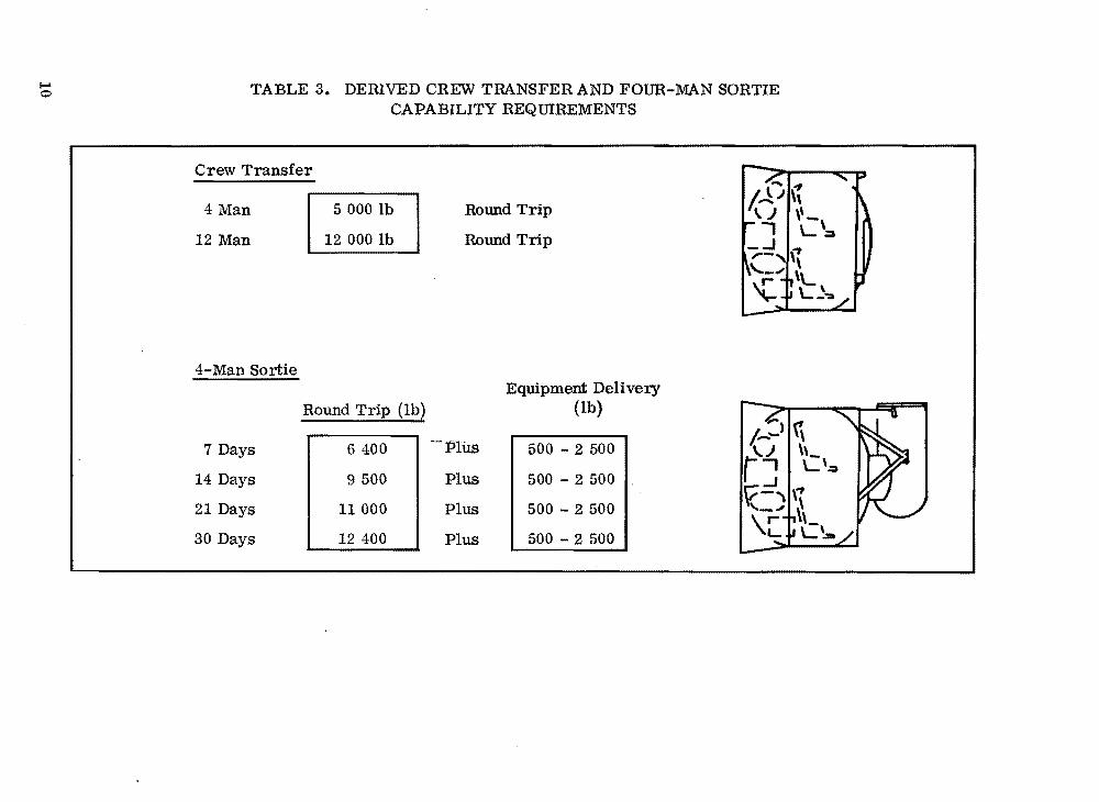
Table 3 presents the weight requirements for transferring crews from low Earth orbit to geosynchronous orbit. During the 1985-1990 time period, transfer of a crew of 4 has been assumed and after 1991 transfer of a crew of 12 has been assumed.
Table 3 also presents the weight requirements for a four-man sortie mission to geosynchronous orbit. In addition to the weights of the module shown. it is desirable that extra payload capability ranging from 500 to 2500 lb be available.
7

• •
00 TABLE 1. GEOSYNCHRONOUS ORBIT - FOUR-MAN STA TIONa
Element Number
Required weight
b
(lb) Length
(ft)
I
Function
Habitability Module
Subsystems Module
Logistics Module
Docking Module
Payload Module
1
1
1
1
1
22 100
24900
17300
10400
18 800
25
26
23
8
-
Crew Quarters, Hygiene, Stowage
Power, Stabilization, etc.
Fluids, Bulk Cargo, Waste Stowage
Docking and Connection of Elements
As required
--
Total Complement 93500 82
a. Reference Geosynchronous Space Station Options, MSFC, July 28, 1975.
b. Weights increased 25 percent from reference to include radiation protection, etc•
40

• • "
TABLE 2. GEOSYNCHRONOUS ORBIT - FOUR-MAN STA TIONa
Element Number
Required Weight . (lb)
Length (ft) Function
Habitability/ Subsystems Module
1 44200 46 Crew Quarters, Power Stabilization, Data Management, etc.
Docking Module
2 5600 ( ea)
12 Allows Docking and Connection of Elements
Logistics Module
1 23600 18 Fluids, Bulk Cargo, Waste Storage, etc.
General Purpose Laboratory
1 20000 20 Laboratory Functions
Total Complement 99000 108
a. 1976 In-House Study - Assembled in Low-Earth Orbit.
(.0
..... o TABLE 3. DERIVED CREW TRANSFER AND FOUR-MAN SORTIE
CAPABILITY REQUIREMENTS
Crew Transfer
4 Man
12 Man
4-Man Sortie
7 Days
14 Days
21 Days
30 Days
•
5000lb
12 000 lb
Round Trip (lbl
6400
9 500
11 000
12 400
Round Trip
Round Trip
Equipment Delivery (lb)
-"'Plus 500 - 2 500
Plus 500 - 2 500
Plus 500 - 2 500
Plus 500 - 2 500
- .,I: \. .J \\- \\) \-,
-, L::a _.J \~ ......-" \ ~-"" 'L ~ L~':A
• •

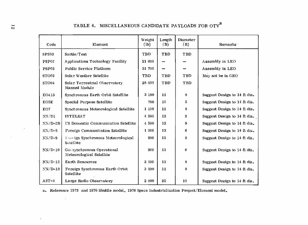
Table 4 presents several miscellaneous candidate payloads for OTV. The payloads were selected from the 1973 and 1976 Shuttle mission models and from the 1976 Space Industrialization project/element model. The configuration (length and diameter) of the automated payloads shown in Table 4 is an important issue for the future OTV and the future Shuttle system. The current configurations do not fit well in the Space Transportation System (STS) payload envelope .. capability. Previous standard spacecraft studies have identified this problem and have indicated that many of these payloads could be accommodated by a standard spacecraft which is very short and approximately 14 ft in diameter•.. It is suggested that, where possible, these payloads be redesigned to a 14 ft diameter. The configuration of these payloads is an issue which should be resolved in the near future.
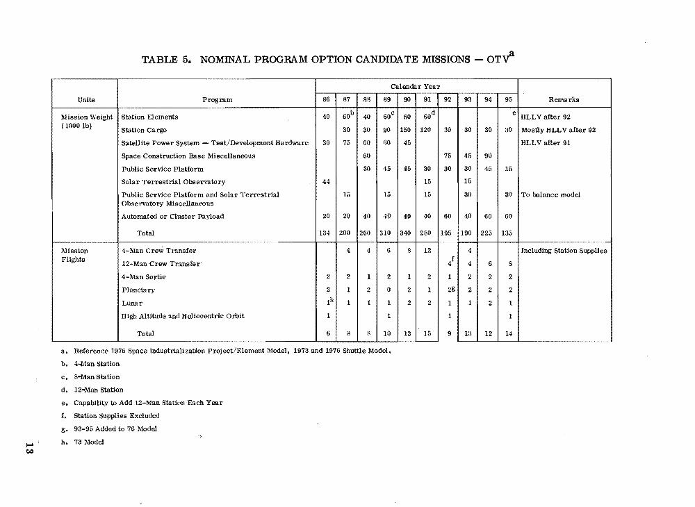
Table 5 presents a tabulation of candidate missions for the high performance OTV for the 1986-1995 time period. These missions are representative of the 1973 and 1976 Shuttle mission models and the 1976 Space Industrialization project/element model. Planetary missions are typical of 1976 plans. In certain cases, additions have been made to balance the model. The candidate missions have been listed by two types: the first being tabulated simply as mission payload weight and the second where individual or particular mission flights are indicated. The missions presented in Table 5 are hereafter referred to as the nominal program for OTV analysis and characterization.
The nominal program model shown in Table 5 is representative of a rather ambitious space program during the 1986-1995 time period. Although this model seems ambitious today, major programs being planned, such as the space power program or extensive development of the public services program, could result in a program much more ambitious than shown. It is not expected, however, that this type increase in programs would have a major effect on the transportation systems being considered. However, a less ambitious program may have some effect and is introduced here to determine the effects of a reduced actiVity.
Table 6 presents a tabulation of candidate missions for the high per-' formance OTV with major reductions in activities. Table 6 is similar to Table 5 with the major difference being .a 10 year delay in the space power program and major reductions or delays in other programs. It is noteworthy that the manned• sortie mission capability is probably more important in the reduced program than in the nominal program.
The manned sortie mission capability is an important issue for OTV and future Space Shuttle capability selection and requirements should be firmly established and characterized in the near future.
11
• •
a ..... TABLE 4. MISCELLANEOUS CANDIDATE PA YLOADS FOR OTVI:\:)
Code Element Weight
(lb) Length
( ft) Diameter
( ft) Remarks'
SPS03 Sortie/Test TBD TBD TBD
PSP02 Applications Technology Facility 21600 - - Assembly in LEO
PSP03 Public Service Platform 31700 - - Assembly in LEO
ST003 Solar Weather Satellite TBD TBD TBD May not be in G EO
ST004 Solar Terrestrial Observatory Manned Module
28600 TBD TBD
E0413 Synchronous Earth Orbit satellite 3 100 11 8 Suggest Design to 14 ft dia.
E05E Special Purpose Satellite 700 10 5 Suggest Design to 14 ft dia.
E07 Synchronous Meteorological Satellite 1 100 11 8 Suggest Design to 14 ft dia.
~X/D1 INTELSAT 4 500 13 9 Suggest Design to 14 ft dia. -XX/D-2B l'S Domestic Communication Satellite 4 500 13 9 Suggest Design to 14 ft dia.
KN/D-5 Foreign Communication Satellite 1 000 13 6 Suggest Design to 14 ft dia.
NK/D-9 1111 dgn Synchronous Meteorological S~,tellite
900 11 9 Suggest Design to 14 ft dia.
NN/D-10 Ge',3ynchronous Operational Meteorological Satellite
900 11 6 Suggest Design to 14 ft dia.
NN/D-12 Earth Resources 3 100 11 8 Suggest Design to 14 ft dia.
XN'/D-13 Foreign Synchronous Earth Orbit Satellite
3100 11 8 Suggest Design to 14 ft dia.
AST-8 Large Radio Observatory 2800 25 10 Suggest Design to 14 ft dia.
a. Reference 1973 and 1976 Shuttle model, 1976 Space Industrialization Project/Element model•
t
.,f•
TABLE 5. NOMINAL PROGRAM OPTION CANDIDATE MISSIONS - OT~
Units Program
. Calendar Year
Remarks86 87 88 89 90 91 92 93 94 95
Mission Weight Station Elements 40 60b 40 60c 60 60d
e HLLV after 92 (1000 lb)
Station Cargo 30 30 90 150 120 30 30 30 30 Mostly HLLV after 92
Satellite Power System Test/Development Hardware 30 75 60 60 45 HLLV after 91
Space Construction Base Miscellaneous 60 75 45 90
Public Service Platform 30 45 45 30 30 30 45 15
Solar Terrestrial Observatory 44 15 15 I
Public Service Platform and Solar Terrestrial Observatory Miscellaneous
15 15 15 30 30 To balance model
Automated or Cluster Payload 20 20 40 40 4P 40 60 40 60 60
Total 134 200 260 310 340 280 195 190 225 135
Mission 4-Man Crew Transfer 4 4 6 8 12 4 Including Station Supplies •
Flights 12-Man Crew Transfer' 4f 4 6 8
4-Man Sortie 2 2 1 2 1 2 1 2 2 2
Planetary 2 1 2 0 2 1 2g 2 2 2
Lunar Ih 1 1 1 2 2 1 1 2 1
High Altitude and Heliocentric Orbit 1 1 1 1
Total 6 8 8 10 13 15 9 13 12 14
a. Reference 1976 Space Industrialization Project/Element Model, 1973 and 1976 Shuttle Model.
b. 4-ll.1an Station
c. &oMan Station
d. 12..J'dan station
e. Capability to Add 12-Man Station Each Year
f. Station Supplies Excluded
g. 93-95 Added to 76 Model
.... h. 73 Model \:t.)

• • •
I-' TABLE 6. LOW PROGRAM OPTION CANDIDATE MISSIONS - OT~ ~
CaleDdar Year
Units Progmm 116 87 88 89 90 91 92 93 !14
MiNion Weight Station Elements 40 GOb 40c 4. (lOO0Ib) Station Cargo 45 45 45 45 60
Satellite Power System - Test/Development Hardware 30d 30 45
Space Construction Baae Miscellueoua 30 30
Public Service Platform 15 15 15 15 15
Solar Terrestrial Observatory 15 30 15
Public ServiCE: Platform and Solar Terreltrlal 15 15 30 Observatory Miscellaneoua
Automated or Cluster Payl_d 2t 20 4e 40 ; 4J 40 GO 40 'I,
Total 65 10 125 115 i55 100 140 135 2.5
Mlllsion 4-Man Crew Tranafer 3 4 6 4 6 4 Flights 12-Man Crew Transfer None
4-Man Sortie
[ I 21 : 1
2 1 ~ 1 2 1 ~el 2 [ ~fIPlanetary
Lunar None
High Altitude and Heliocentric Orbit None
Total 2 4 5 7 8 7T 8 1 7 -
95 RlIII'arkll
40
45
" To IIalance Medel
15
To ..lance MedII
" Same .. Nem1nal Precnm
220
6 1nc1U111Dc StaUen SlIppU..
2 I 8
a. Reference 1976 Space Industrialization Project/Element Model, 1973 and 1976 Shuttle Model (major reductiOIlll a ..umed).
b. 4-Man Station
c. 4-Man Station (8-Man StatiOD Part Time)
d. SPS Program Delayed 10 Years
e. Added to Model

•
•
•
v. OlV CONCEPTS (CONFIGURATIONS)
A. lox/Hydrogen Propellant Concepts The lox/hydrogen high performance vehicle has been considered the
primary candidate for the post-1985 time period in the overall OTV study activities. Early in the latest study activity, it was determined that a capability somewhat larger than could be provided by the current 65 000 lb Shuttle capability might be desirable. For this reason, configuration data for Shuttle capabilities from 65 000 to 125 000 lb have been investigated, and parametric data for the range have been developed.
1. All-Propulsive Orbit Transfer Vehicle (APOTV). 1 A Shuttle compatible APOTV has been extensively studied by MSFC and MSFC contractors. The resulting design configuration has been selected as, a baseline configuration for the in-house OTV study activity. This baseline stage utilizes an RL-10Category lIB engine (see section on propulsion and Appendix A) with I approxi
.' ~
mately 456.5 sec for lox/hydrogen when used at a 6: 1 (lox/hydrogen) mixture ratio.
The baseline APOTV configuration is shown in Figure 2. It should be noted that this design is for delivery only and has a usable propellant load of approximately 52 200 lb. If the configuration was used in a round trip mode, the tankage would be inadequate for utilization of the full 65 000 lb Shuttle capability. The latest configuration concepts utilize a somewhat shorter engine system and have considered both 6:1 and 7:1 propellant mixture ratios. The appropriate APOTV for these characteristics is shown in Figure 3.
As the propellant loading of the stage increases, the lox tank is permitted to grow in diameter to equal the diameter of the hydrogen tank. Figure 4 shows the APOTV for a 125 000 lb Shuttle capability.
Previous OTV studies have included a tilt table and accessories which would remain in the Shuttle. The tilt table would increase the dimensions shown in Figures 2 and 4 by approximately 2 ft. The tare weight in the Shuttle would_ be '2. 9 percent of the Shuttle capability. Shuttle capability in each case has been reduced by the tare weight.
The APOTV length versus propellant loading is shown in Figure 5. Propellant capacities used for Figure 5 cover the range needed for the 65000-to 125 000 lb Shuttle capabilities. Shuttle attachment length is not considered here.
1. Formerly Space Tug.
15

116.0 OtA.
SPACECRAFT INTERFACE RtNQ
LH2 SUPPORT STRUT (16 PLACES)
THRUST STRUCTURE (8 STRUTS)
RLIO<ATII8 (NOZZLE RETRACTED)
..-______________ BOOVSHELL ________---__~
360.01 130 FT)
Figure 2. Baseline APOTV configuration.
28 FT 7:1 MR
-,29 FT 6:1 MR
,
T/ ""-\,t \
J \ 176 IN.
/ \ / 1- ./ ", ../" --HiPc ENGINE
Figure 3. APOTV - 50 200 lb propellant for 65 000 lb Shuttle.
16
•
•
•

• r
..
•
40.5 FT 7:1 MR 42.7 FT 6:1 MR
-........ ",--
'\ / \ I I \
/ \ / / "- - - ----""'"
Figure 4. APOTV 95 000 lb propellant for 125 000 lb Shuttle.
45
40
35
30
m:____~~----~~----~~------L-----~20 80 100 120
PROPELLANT CAPACITY (1000 LBI
Figure 5. APOTV length versus propellant loading.
17
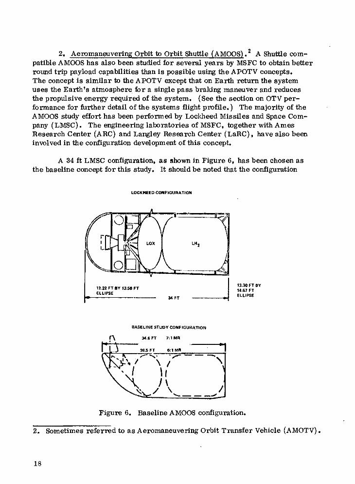
2. Aeromaneuvering Orbit to Orbit Shuttle (AMOOS). 2 A Shuttle compatible AMOOS has also been studied for several years by MSFCto obtain better round trip payload capabilities than is possible using the APOTV concepts. The concept is similar to the APOTV except that on Earth return the system uses the Earth fS atmosphere for a single pass braking maneuver and reduces the propulsive energy required of the system. (See the section on OTV perfonnance for further detail of the systems flight profile.) The majority of the AMOOS study effort has been perfonned by Lockheed Missiles and Space Company (LMSC). The engineering laboratories of MSFC, together with Ames Research Center (ARC) and Langley Research Center (LaRC), have also been involved in the configuration development of this concept.
A 34 ft LMSC configuration, as shown in Figure 6, has been chosen as the baseline concept for this study. It should be noted that the configuration
LOCKMEED CONfiGURATION
12.22 fT BY 13.58 FT eLLiPse
34FT
BASELINE STUDY CONfiGURATION
34.6 FT 7: 1 MR
6:1 MR "1-.,----\ I , \ I J\ I
/ \ '- --"'"
13.30 FT BY 14.67 FT eLLIPSE
Figure 6. Baseline AMOas configuration.
2. Sometimes referred to as Aeromaneuvering Orbit Transfer Vehicle (AMOTV).
18
•
•
•

•
..
to
involves both ogival/elliptical shapes and tapers along the external length of the stage. The configuration shown was designed to accommodate 48 500 lb of propellant which is required for a round trip mission. It uses 6: 1 mixture ratio with a 456.6 sec I RL-10-IIB engine. It is used with a 65 000 lb Shuttle capability. sp
If the AMOOS were designed for delivery only, as was the case with the APOTV, only 42 000 to 43 000 lb of propellant would be required, and the stage could be somewhat shorter•
The tankage bulkhead designs by LMSC are somewhat flatter than that used for the APOTV. To make the AMOOS data more comparable with APOTV data, the tanks were resized and reshaped using ..[2 elliptical bulkheads. A later propulsion system concept was also used. The resulting AMOOS configuration for the 65 000 lb Shuttle, which is directly comparable with the APOTV shown earlier, is shown in Figure 7.
34.6 FT 7:1 MR 36.5 FT 6:1 MR
Figure 7. AMOOS - 48 500 lb propellant for 65 000 lb Shuttle capability.
The LMSC studies do not involve using the APOTV-type tilt table for Shuttle deployment. Shuttle deployment and support of the concept are still ,.. issues for the AMOOS. For the purpose of this study, a Shuttle tare weight of 2.9 percent (same as APOTV) of the Shuttle capability has been assumed.
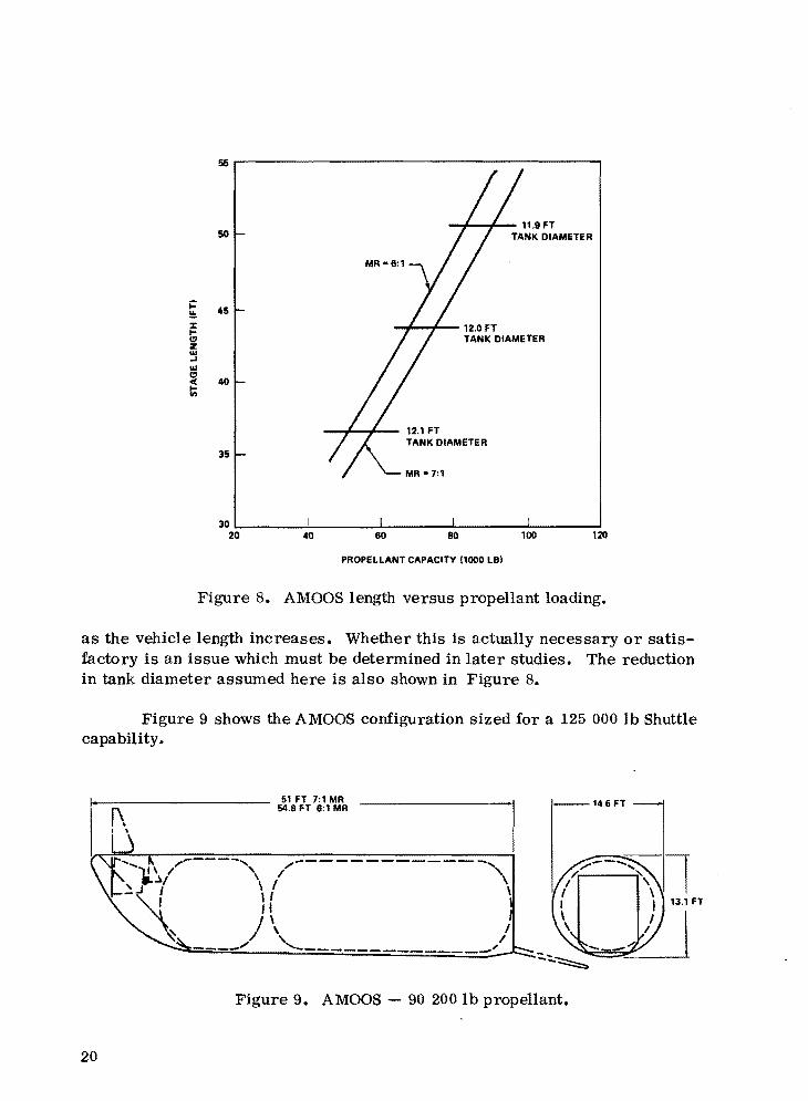
The AMOOS length versus propellant loading is shown in Figure 8. These propellant capacities cover the range needed for the 65 000 to 125 000 lb Shuttle capabilities. In developing these AMOOS configurations, it has been assumed that the same external taper angle used on the baseline configuration would be maintained. This results in using a somewhat different tank diameter
19
oo~----------------------------------------~
50 ...,f-w+-- 11.9FT
TANK DIAMETER
~ 45!.!o
i!: 12.0 FT (lI TANK DIAMETER z .... .... .... (lI
40« In
12.1 FT TANK DIAMETER
35
30~______~______~______~________~______~
20 40 120
PROPELLANT CAPACITY 11000 LBI
Figure 8. AMOOS length versus propellant loading.
as the vehicle length increases. Whether this is actually necessary or satisfactory is an issue which must be determined in later studies. The reduction in tank diameter assumed here is also shown in Figure 8.
Figure 9 shows the AMOOS configuration sized for a 125 000 lb Shuttle capability.
~\, \
20
51 FT 7:1 MR 54.8 FT 6:1 MR
/-------------....., / \
\
Figure 9. AMOOS - 90 200 lb propellant.
•

The internal arrangement and external configurations of the AMOOS require further study effort. It is expected that significant reductions in stage length may be possible. The subject is discussed further in the section on cargo bay length issues•
• B. Space Storable Propellant Concepts
Extended mission duration problems associated with cryogenic hydrogen,• cargo bay length, and general space storability associated with liquid hydrogen
have dictated the need for a propellant combination with high bulk propellant density and which is somewhat easier to store in space. For this reason, two different propellant combinations have been considered. In the first case lox and rocket propellant (RP), where lox is considered a space storable, were investigated. In the" second case nitrogen tetroxide (N20 4) and monometbyl-~ hydrazine (MMH) were investigated.
The two storable configurations have not been studied to the same detail level as have the lox/hydrogen configurations. However, parametric configuration, weight, and performance data have been developed. The configurations studied include the AMOOS and the APOTV concepts.
Configuration sketches for the storable propellant configurations are shown in Figures 10 and 11. To simplify weight calculations and permit ease of developing parametric data, the configurations studied have used rather conventional tankage design. These designs do not efficiently utilize the Shuttle cargo bay, and if the storable propellant systems are to be considered as serious competitors, further configuration development is required.
Figure 10. APOTV lox/RP and N20 4/MMH.
21
• Figure 11. AMOOS lox/RP and N20.j./MMH.
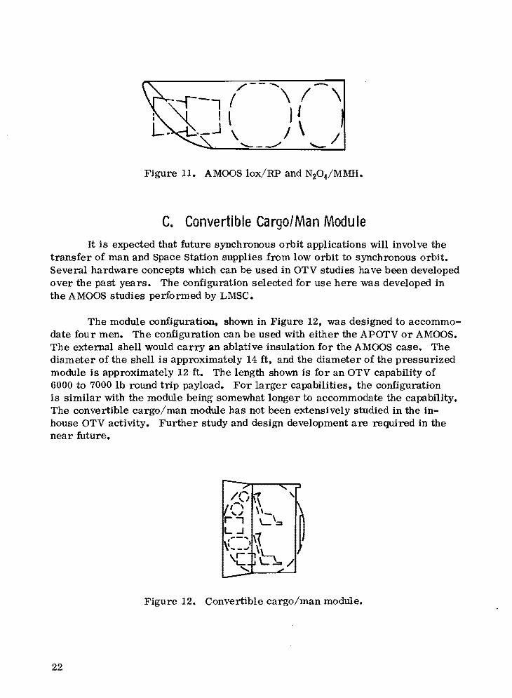
C. Convertible Cargo/Man Module It is expected that future synchronous orbit applications will involve the
transfer of man and Space Station supplies from low orbit to synchronous orbit. Several hardware concepts which can be used in OTV studies have been developed over the past years. The configuration selected for use here was developed in the AMOOS studies performed by LMSC.
The module configuration, shown in Figure 12, was designed to accommodate four men. The configuration can be used with either the APOTV or AMOOS. The external shell would carry an ablative insulation for the AMOOS case. The diameter of the shell is approximately 14 ft, and the diameter of the pressurized module is approximately 12 ft. The length shown is for an OTV capability of 6000 to 7000 lb round trip payload. For larger capabilities, the configuration is similar with the module being somewhat longer to accommodate the capability. The convertible cargo/man module has not been extensively studied in the inhouse OTV activity. FUrther study and design development are required in the near future.
Figure 12. Convertible cargo/man module.
22
•
..
D. Emergency Return Vehicle Configurations As is the case with ships on the high seas, it is likely that a lifeboat type
system will be provided for use in emergency situations. It has been assuIl,)ed here that such a system should be able to return directly to the Earth with an option of stopping in low Earth orbit. It seems most likely that any system used for this purpose would utilize aeromaneuvering or aerobraking.
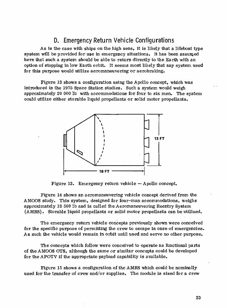
Figure 13 shows a configuration using the Apollo concept, which was introduced in the 1975 Space Station studies. Such a system would weigh approximately 20 000 lb with accommodations for four to six men. The system could utilize either storable liquid propellants or solid motor propellants.
, \ \
I I
I
\, I, I
I
1----- 18 FT ------.1 Figure 13. Emergency return vehicle Apollo concept.
Figure 14 shows an aeromaneuvering vehicle concept derived from the AMOOS study. This system, designed for four-man accommodations, weighs approximately 13 500 lb and is called the Aeromaneuvering Reentry System (AMRS). Storable liquid propellants or solid motor propellants can be utilized.
The emergency return vehicle concepts previously shown were conceived for the specific purpose of permitting the crew to escape in case of emergencies. As such the vehicle would remain in orbit until used and serve no other purpose•
The concepts which follow were conceived to operate as functional parts of the AMOOS OTS, although the same or similar concepts could be developed for the APOTV if the appropriate payload capability is available.
Figure 15 shows a configuration of the AMRS which could be nominally used for the transfer of crew and/or supplies. The module is sized for a crew
23

WASTE MANAGEMENT
25 FT
Figure 14. Aeromaneuvering Reentry System.
114-·------- 33.5 FT
Figure 15. Aeromaneuvering Reentry System (crew and cargo accommodations) •
of four and for station supplies for a crew of four for 90 days. The system could be converted to accommodate a crew of 12 or more. The configuration as shown in Figure 15 could use portions of the external shell of the AMOOS high performance stage. It would remain with the crew for the period the crew remained on orbit. It could then, or at any time an emergency arises, return to low Earth orbit or directly to Earth.
It is envisioned that the station supplies would only be off-loaded as required and at least during the early portion of the orbit stay would remain onboard for crew usage if needed•. This capability would permit the crew to remain on orbit and perhaps perform emergency operations, if required, after abandoning the station.
24
•
,
•

•
•
The storable propulsion system would always be used to deorbit the AMRS, and the OTV would usually be used only as a delivery system.
The OTV study activity, to date, indicates that this mode of operation would require approximately the same payload capability as the convertible cargo/man module concept. The operations cost, however, would be considerably higher because there would be two stages plus heat shields to refurbish after each launch. Also a Shuttle capability greater than 100 000 lb is probably required.
Figure 16 shows an AMRS configuration which avoids the stage and heat shield refurbishment on each launch. As with the previously described configuration, crew and cargo are accommodated. In this case, however, only the cargo/man module is transferred between orbits each time. The AMRS serves as a berth for the convertible cargo/man module while it is on orbit.
v = 1150 CONVERTIBLE CARGO/MAN MODULE
Figure 16. Aeromaneuvering Reentry System (convertible cargo/man module berth).
This concept is somewhat shorter since the propulsion system is located at the forward end. Since the AMRS is only transported to synchronous orbit one time, an airlock can be provided without significant transportation cost· penalty•
E. Orbit-Based Service Vehicles Although it is recognized that some type of manned service vehicle will
be used in the synchronous operation, very little development effort has been performed on it. The main consideration here has been to identify concepts
25
whereby the service vehicle would be a derivative of other hardware involved in the OTS. It is assumed that some type airlock would be desirable on any service vehicle.
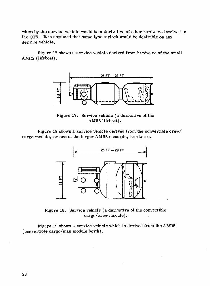
Figure 17 shows a service vehicle derived from hardware of the small AMRS (lifeboat).
26 FT -28 FT
Figure 17. Service vehicle (a derivati ve of the AMRS lifeboat).
Figure 18 shows a service vehicle derived from the convertible crew/ cargo module, or one of the larger AMRS concepts. hardware.
lLl. C")...
I 26 FT -28 FT -I
Figure 18. Service vehicle (a derivative of the convertible cargo/crew module) •
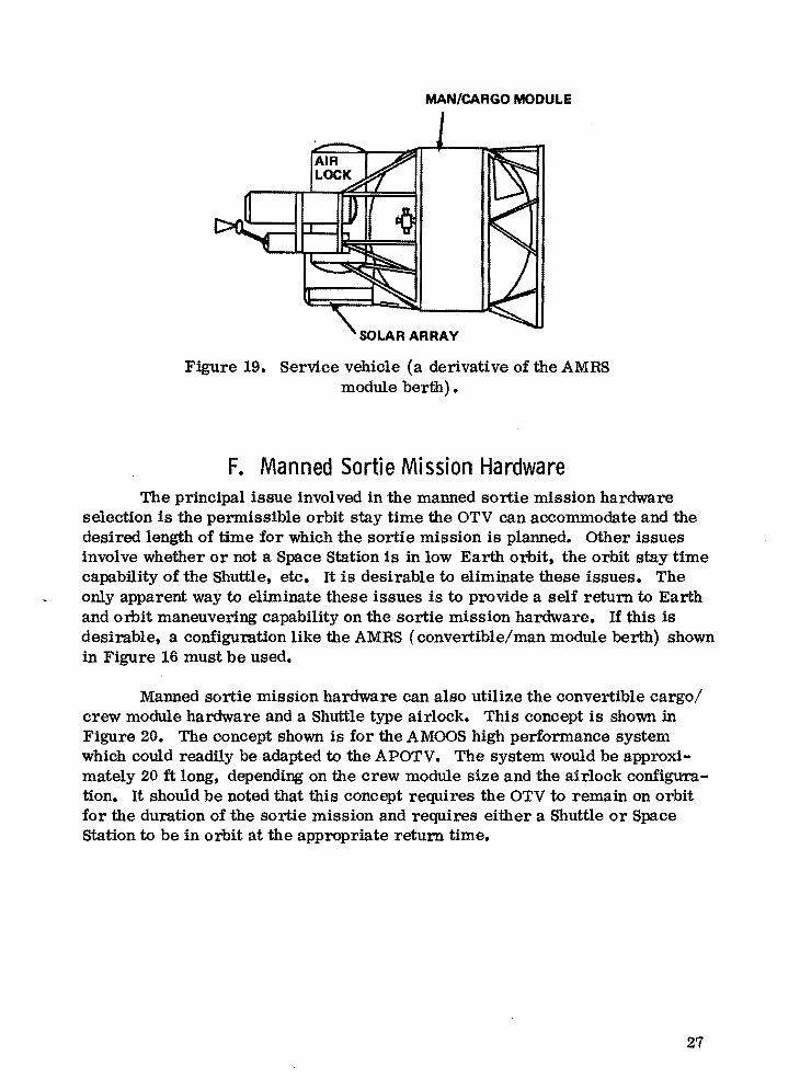
Figure 19 shows a service vehicle which is derived from the AMRS (convertible cargo/man module berth).
26
..
•
MAN/CARGO MODULE
•
Figure 19. Service vehicle (a derivative of the AMRS module berth) •
F. Manned Sortie Mission Hardware The prinCipal issue involved in the manned sortie mission hardware
selection is the permissible orbit stay time the OTV can accommodate and the desired length of time for which the sortie mission is planned. Other issues involve whether or not a Space Station is in low Earth orbit, the orbit stay time capability of the Shuttle, etc. It is desirable to eliminate these issues. The only apparent way to eliminate these issues is to provide a self return to Earth and orbit maneuvering capability on the sortie mission hardware. If this is desirable, a configuration like the AMRS (convertible/man module berth) shown in Figure 16 must be used.
Manned sortie mission hardware can also utilize the convertible cargo/ crew module hardware and a Shuttle type airlock. This concept is shown in Figure 20. The concept shown is for the AMOOS high performance system which could readily be adapted to the APOTV. The system would be approximately 20 ft long, depending on the crew module size and the airlock configuration. It should be noted that this concept requires the OTV to remain on orbit for the duration of the sortie mission and requires either a Shuttle or Space Station to be in orbit at the appropriate return time•
..
27

-20 FT
r----,"
I
,..1---- 1'-, ICREW MODULE
'\ I
\',:\1
AT 1150 FT3
AIR LOCK r--~ / ATII ... 150F~ ...I 'TI •
f,\ ~ i\, ---,!1--- • ,
•/" .." I
I
" 1----
Figure 20. Manned sortie configuration (convertible cargo/crew module).
G. Docking (Loadi ng/ Un loadi ng) Module Configu ration Space station studies, to date, have not developed appropriate station
element configurations for the OTS hardware concepts which have been developed in this study. Low Earth orbit stations must interface with the Space Shuttle system which is somewhat different than the OTS. Also, low Earth orbit stations do not assume the need for lifeboat or emergency return type systems. Transfer transportation to synchronous orbit is very expensive, and the eventual selected docking module concept must favor, as much as possible, the OTV or OTS because it is only delivered to orbit one time (i. e., if a penalty is necessary or desirable, it should be placed on the docking module and not on the OTS).
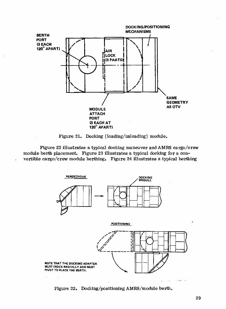
The docking module concept shown in Figure 21 is introduced to illustrate the desirable accommodations from an OTV point-of-view. This configuration and the operation concept sketches which follow are illustrative of OTV requirements on the Space Station.
It has been assumed that it would be desirable to have some overlap of crew accommodations during the crew exchange period. This requires accommodations for multiple crew modules. It is assumed that it may be desirable to have accommodations for extra cargo modules and perhaps a service vehicle. It has also been assumed that some type of airlock between any berth and the Space Station proper is required.
28
•
BERTH PORT ",. (3 EACH / 120° APART)
MODULE ATTACH PORT (3 EACH AT 120° APART)
DOCK INGIPOSITIONING MECHANISMS
J /
/
SAME GEOMETRY ASOTV
Figure 21. Docking (loading/unloading) module.
Figure 22 illustrates a typical docking maneuver and AMRS cargo/crew module berth placement. Figure 23 illustrates a typical docking for a convertible cargo/crew module berthing. Figure 24 illustrates a typical berthing
RENDEZVOUS
NOTE THAT THE DOCKING ADAPTER MUST INDEX RADIALLV AND MUST PIVOT TO PLACE THE BERTH.
POSITIONING
DOCKING MODULE
Figure 22. Docking/positioning AMRS/module berth.
29

DOCKING~
r-POSITIONING
NOTE THAT THE DOCKING ADAPTER MUST MODULE INDEX RADIALLY AND ROTATE ABOUT A TRANSFER POINT JUST OUTSIDE THE RING CIRCUMFERENCE TO ARRANGE THE MODULE IN TRANSFER POSITION.
Figure 23. Docking/positioning/module transfer.
MODULE POSITIONED AT AIRLOCK TYPICAL
REMOVAL FROM BERTH OR AIRLOCK OR OTV AND POSITION TO BERTH OR AIRLOCK OR OTV
NOTE THAT DOCKING ADAPTER MUST INDEX-ROTATE-PIVOT AND EXTEND.
Figure 24. Module transfer/placement.
30

•
or placement of a cargo module or storage of a crew module. Figure 25 presents an end view of the orbital assembly. Specific requirements on the docking and placement hardware are mentioned. The configurations shown are typical of the AMOOS utilization; however, APOTV requirements would be similar.
MODULE STORAGE LOAD/UNLOAD
MODULE BERTH POSITION
CAMRS-LIFEBOAT) ,±!MANNED ,. __ MODULE 1--_ ~
• • ~- -~" "",,/
ORBIT BASED SERVICE VEHICLE
DOCKING MODULE
"""..,... MODULE STORAGE
/ "'Ill'.. ~ LOAD/UNLOAD't- POSITION MODULE STORAGE --..,. LOADIUNLOAD POSITION,
MANNED MODULE
I I '/)\('.L/~
MODULE BERTH tAMRS-LIFEBOAT)
Figure 25. End-view docking system.
H. Unique Designs to Obtain Shorter Stages Shuttle cargo bay length availability. may necessitate unique designs fpr
OTV to be able to carry the OTV and payloads in the same Shuttle. This is particularly true if the Shuttle capability is improved significantly and if the cargo bay length is not extended beyond 60 ft.·
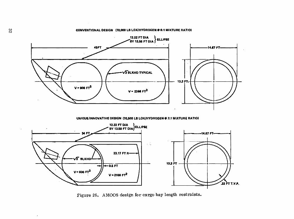
The configurations shown in Figures 2 through 9 involved somewhat conventional design with tJ2 ellipsoidal bulkheads as shown on the AMOOS configuration in Figure 26. This particular configuration is sized for a round trip mission for a 100 000 lb Shuttle payload capability. As can be seen, the stage is approximately 45 ft long, which is probably unacceptable, and if the design is unchanged the 100 000 lb Shuttle capability would probably be impractical.
31
.1
c:,.:)
""
..
CONVENTIONAL DESIGN (70.000 LB LOx/HVDROGEN 0 8:1 MIXTURE RATIO)
12.22 FT DIA }BV 'UI FT DIA ELLIPSE
1----14.17"'
I -vlBLKHD TYPICAL
13.3 FT.--I.11-+1--
V-800 Fyi V- 2311 F13
UNIQUE/INNOVATIVE DESIGN (70.100 LB LOXfHVDROGEN 0 7;1 MIXTURE RATIO)
12.22 FT DIA }BY 13.68 FT DIA ELLIPSE
1-----'14.61 FT .1
23.17 FT R
0.& FT 13.3 FT I I + I I
V-Z100 n2
Figure 26. AMOOS design for cargo bay length restraints.
., •

Figure 26 also shows a unique/innovative design using nestled central bulkheads and a very low profile forward bulkhead to improve volumetric efficiency. The tanks would be tapered and elliptical in cross section to match the external shell of the AMOOS. A somewhat simpler, but similar, design could be devised for the APOTV •
• The unique design also uses a 7: 1 (lox/hydrogen) mixture ratio which. saves approximately 2 ft. A 6 percent ullage space is provided for both cases. Other possibilities for reducing stage length are:
•
1. Reduce ullage to 4 percent @ ~ 0.4 ft
2. Use 8: 1 mixture ratio @ ~ 1.5 ft
3. Use 9: 1 mixture ratio @ ~ 2.7 ft
4. Use slush hydrogen @ ~ ???? ft
5. Reshape exterior configuration @ ???? ft.
The problem of unique design to obtain shorter stage length is an issue of paramount importance and should be investigated in the near future. The problem is discussed further in the section on cargo bay length considerations.
I. 100000 Ib Capabi lity ShuttlelAMOOS Cargo Bay Configurations
It is difficult to visualize the problems associated with OTV, OTV payloads, and the 60 ft cargo bay. In this section an attempt has been made to correlate the payloads and OTV in a manner where both can be included in one 60 ft cargo bay. It is assumed that the appropriate AMOOS (unique/innovative design) can be limited to 34 ft length and that payloads can be limited to 24 it length. Figure 27 shows the AMOOS type OTS Shuttle cargo bay configurations which were previously described.
The Shuttle airlock is used nominally for the crew transfer flights. Since the sortie mission hardware includes an airlock (and since there is not enough cargo bay length to use a Shuttle airlock), it is assumed that the sortie airlock would be used for crew loading and unloading.
Figure 28 shows typical AMOOSflight configurations when the system is being used for major propulsion events. The AMRS orbital and landing configurations are also shown.
33

• •
~ ~
SINGLE SHUTTLE LAUNCH
~:!~
SHUTTLE PAYLOAD (LOW EARTH ORam CAPABllI'ry' .'00,000 LB
STAGE AND PAYLOAD IN SAME SHUTTLE CARGO BAY-LENGTH.
AMOOILENGTH ALLOWABLE (REQUIRES UNIQUE DESIGN, i.e. NESTLED BULKHEADS, TAPERE[)'OOIVAL TANKS, 7:1 MIXTURE RATIO, etc.1
PAYLOAD LENGTH ALLOWABLE
LENGTH TOLERANCE
80 FT
34 FT
24FT
2fT
CARGO BAY CONFIGURATIONS
"MANNED SORTIE
CREW/CARGO TRANSFER
AUTOMATED PAYLOADS
STATION ELEMENTS LARGE PAYLOADS ETC.
r-' , - "
t • ,..'
.~ [~JIII Rf& DJ]tIIB~ ~FII'I~~
(SHUTTLE CARGO BAY LENGTH 60 FEET
CAPABILITIES (SYNCHRONOUS ORBIT'
DELIVERY PAYLOADS 21,000-22,000 LI
ROUND TRIP PAYLOADS 12.,100-13,000 LI
Figure 27. Single Shuttle/AMOOS (100 000 lb Shuttle payload capability) •

Ok
AMRS ORBITAL CONFIGURATION
PAYLOAD DELIVERY CONFIGURATION
CARGO/MAN TRANSFER CONFIGURATION
AMRS LANDING CONFIGURATION
c:,,:) C1 Figure 28. Typical AMOOS flight configurations.

J. Unmanned Payload Configurations Previous transportati.n studies have shown the desirability to provide
more efficient cargo bay utili.aation 8y unmanned payloads. The unmanned orbital platform study performed for MSFC by Rockwell International (RI) developed a payload c.ncept which ceuld be used to obtain the desired effect. RI also showed that the concept would be applicable to most automated payloads •and could be considered as a standard spacecraft (Fig. 29).
Figure 29. Unmanned orbital platform.
36

•
•
•
VI. WEIGHT DATA
Several previous study and design efforts are available for weight references for OTV. Primarily the reference data deal with hydrogen- and oxygentype stages. Baseline stage weights for the APOTV used herein were taken from report MSFC 68 M00039-2, "Baseline Space Tug Configuration Definition," dated July 15, 1974. Baseline stage weights for the AMOOS, the AMRS, and the small man module were taken from report LMSC-HREC TR D49633, "Application Study of Aeromaneuvering Orbit-to-orbit Shuttle (AMOOS)," dated January 1976. These baseline data were taken as a starting point for the parametric weight data which follow. It is recognized that in some cases the baseline data are not exactly comparable. The error, however, should only be on the order of a few hundred pounds. Future OTV studies should deal with correcting these discrepancies.
A. Lox/Hydrogen Propellant Stages
Weight data for the AMOOS and APOTV concepts are included here. In addition a drop tank system using lox/hydrogen is given.
The baseline weights used for the APOTV are shown in Table 7. This system was designed for a 65 000 lb Shuttle capability delivery mission.
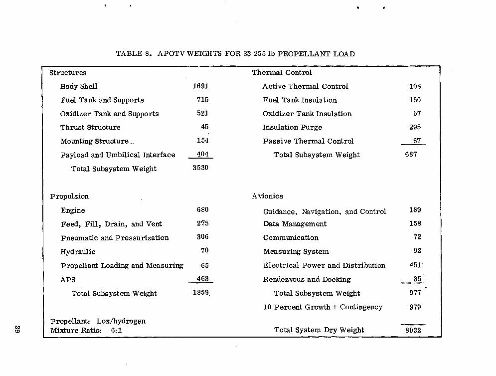
Weights for higher propellant loadings are shown in Tables 8 and 9. Parametric weight data for APOTV reflecting propellant capacities suitable for Shuttle capabilities ranging from 65 000 to 125 000 lb are shown in Figure 30.
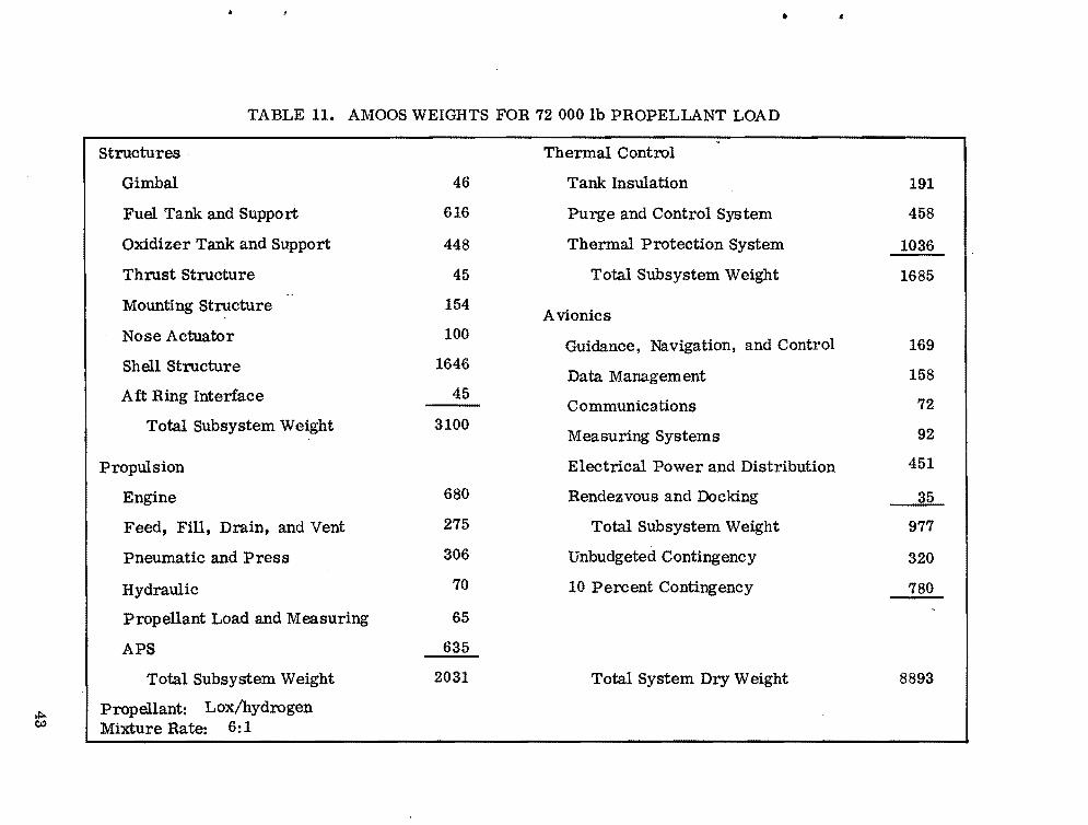
The baseline weights for the AMOOS are shown in Table 10. This system was designed for a 65 000 Ib Shuttle capability round trip mission. Weights for higher propellant loads are shown in Tables 11 and 12. Parametric weight data for AMOOS reflecting capacities ranging from 65 000 to 125 000 lb are shown on Figure 31. '
B. Lox/Hydrogen Propellant Drop Tanks Several NASA transportation studies have considered using recoverable
lox/hydrogen stages with expendable drop tanks used to supplement the basic stage propellant loading. Weights for such a drop tank with 50 000 Ib of lox/ hydrogen propellant are given in Table 13. These weights were derived by using the design weights developed for the baseline APOTV tankage. Parametric weight data for drop tanks with propellant loadings between 50 000 lb and 100 000 lb are given in Figure 32.
37

00 c,.:) TABLE 7. APOTV BASELINE WEIGHTS
Structures
Body Shell 914
Fuel Tank and Supports 425
Oxidizer Tank and Supports 243
Thrust Structure 29
Mounting Structure __ 100
Payload and Umbilical Interface 263
.Total Subsystem Weight 1947
Propulsion
Engine 442
Feed, Fill, Drain, and Vent 256
Pneumatic and Pressurization 234
Hydraulic 63
Propellant Loading and Measuring 50
APS 301
Total Subsystem Weight 1346
propellant: Lox/hydrogen Mixture Ratio: 6: 1
Thermal Control
Active Thermal Control 70
Fuel Tank Insulation 90
Oxidizer Tank Insulation 40
Insulation Purge 200
Passive Thermal Control 41
Total Subsystem Weight 441
Avionics
Guidance, Navigation, and Control 154
Data Management 158
Communication 72
Measuring System 92
Electrical Power and Distribution 410
Rendezvous and Docking 35
Total Subsystem Weight 921
10 Percent Growth 468
Total System Dry Weight 5150
• <II
•
TABLE 8. APOTV WEIGHTS FOR 83 255 lb PROPELLANT LOAD
Structures
Body Shell
Fuel Tank and Supports
Oxidizer Tank and Supports
Thrust Structure
Mounting Structure._
Payload and Umbilical Interface
Total Subsystem Weight
Propulsion
Engine
Feed, Fill, Drain, and Vent
Pneumatic and Pressurization
Hydraulic
Propellant Loading and Measuring
APS
Total Subsystem Weight
propellant: Lox/hydrogen eo Mixture Ratio: 6:1<:0
1691
715
521
45
154
404
3530
680
275
306
70
65
463
1859
Thermal Control
Active Thermal Control
Fuel Tank Insulation
Oxidizer Tank Insulation
Insulation Purge
Passive Thermal Control
Total Subsystem Weight
Avionics
Guidance, Navigation, and Control
Data Management
Communication
Measuring System
Electrical Power and Distribution
Rendezvous and Docking
Total Subsystem Weight
10 Percent Growth + Contingency
Total System Dry Weight
108
150
67
295
67
687
169
158
72
92
451"
35
977
979
8032
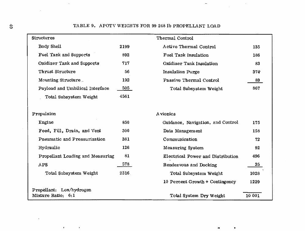
...... <0 TABLE 9. APOTV WEIGHTS FOR 99 248 lb PROPELLANT LOAD
Structures
Body Shell 2199
Fuel Tank and Supports 892
Oxidizer Tank and Supports 717
Thrust structure 56
Mounting Structure _ 192
Payload and Umbilical Interface 505
Total Subsystem Weight 4561
Propulsion
Engine 850
Feed, Fill, Drain, and Vent 300
Pneumatic and Pressurization 381
Hydraulic 126
Propellant Loading and Measuring 81
APS
Total Subsystem Weight 2316
Propellant: Lox/hydrogen Mixture Ratio: 6:1
Thermal Control
Active Thermal Control
Fuel Tank Insulation
Oxidizer Tank Insulation
Insulation Purge
Passive Thermal Control
Total Subsystem Weight
Avionics
Guidance, Navigation, and Control
Data Management
Communication
Measuring System
Electrical Power and Distribution
Rendezvous and Docking
Total Subsystem Weight
10 Percent Growth + Contingency
Total System Dry Weight
135
186
83
374'
89
867
175
158
72
92
496
35
1028
1229
10001
... .

,po.. .....
ai ..J
§ !: I::r: !:a w 3: w CJ « t;
12
11
10
9
8
1
6
5
4
40
STAGE DRY WEIGHT
60 80 100 120
PROPELLANT LOADING (1000 LB)
• •
CONFIGURATION
--r \r ),\..
'--_/
NOTES: 1. LOX/HYDROGEN PROPELLANT AT 6:1 MIXTURE
RATIO.
2. THRUST/IGNITION WEIGHT AT APPROXIMATELY 0.15.
3. STAGE CUTOFF WEIGHT SCALING EQUATION Wg = 5126 +0.09888 (Wp.50 189)
4. DO NOT USE SCALING EQUATION FOR LESS THAN 50 189 LB PROPELLANT LOADING
Figure 30. Lox/hydrogen propellant APOTV weight versus propellant loading.

,.j::.. I:\:) TABLE 10. BASELINE AMOOS WEIGHTS
Structures
Gimbal 30
Fuel Tank and Support 417
Oxidizer Tank and Support 238
Thrust Structure 29
Mounting Structure 100
Nose Actuator 100
Shell Structure 1013
Aft Ring Interface 30
Total Subsystem Weight 1957
Propulsion
Engine 442
Feed, Fill, Drain, and Vent 256
Pneumatic and Press 234
Hydraulic 63
Propellant Load and Measuring 50
APS 500
Total Subsystem Weight 1545
Propellant: Lox/hydrogen Mixture Rate: 6: 1
Thermal Control
Tank Insulation 130
Purge and Control System 311
Thermal Protection System 1036
Total Subsystem Weight 1477
Avionics.
Guidance. Navigation. and Control 154
Data Management 158
Communications 72
Measuring Systems 92
Electrical Power and Distribution 410
Rendezvous and Docking 35
Total Subsystem Weight 921
Unbudgeted Contingency 210
10 Percent Contingency 590
Total System Dry Weight 6700
.."' •
•
TABLE 11. AMOOS WEIGHTS FOR 72 000 lb PROPELLANT LOAD
H>e.:>
Structures·
Gimbal
Fuel Tank and Support
Oxidizer Tank and Support
Thrust Structure
Mounting Structure
Nose Actuator
Shell Structure
A ft Ring Interface
Total Subsystem Weight
Propulsion
Engine
Feed, Fill, Drain, and Vent
Pneumatic and Press
Hydraulic
Propellant Load and Measuring
APS
Total Subsystem Weight
Propellant: Lox/hydrogen Mixture Rate: 6:1
46
616
448
45
154
100
1646
45
3100
680
275
306
70
65
635
2031
Thermal Control
Tank Insulation
Purge and Control System
Thermal Protection System
Total Subsystem Weight
Avionics
Guidance, Navigation, and Control
Data Management
Communications
Measuring Systems
Electrical Power and Distribution
Rendezvous and Docking
Total Subsystem Weight
Unbudgeted Contingency
10 Percent Contingency
Total System Dry Weight
191
458
1036
1685
169
158
72
92
451
35
977
320
780
8893

,.j:::.. ,.j:::.. TABLE 12. AMOOS WEIGHTS FOR 90 200 lb PROPELLANT LOAD
Structures Thermal Control
Gimbal 58 Tank Insulation 243
Fuel Tank and Support 787 Purge and Control System 582
Oxidizer Tank and Support 632 Thermal Protection System 1036
Thrust Structure 56 Total Subsystem Weight 1861
Mounting Structure 192 Avionics
Nose Actuator
Shell Structure
Aft Ring Interface
100
2192
60
Guidance, Navigation, and Control
Data Management
Communications
175
178
72 Total Subsystem Weight 4077
Measuring Systems 92
Propulsion Electrical Power and Distribution 496
Engine 850 Rendezvous and Docking 35
Feed, Fill, Drain, and Vent 300 Total Subsystem Weight 1028
Pneumatic and Press 381 Unbudgeted Contingency 400
Hydraulic 126 10 Percent Contingency 950
Propellant Load and Measuring 81
APS 730
Total Subsystem Weight 2468 Total System Dry Weight 10784
Propellant: Lox/hydrogen Mixture Rate: 6:1
f
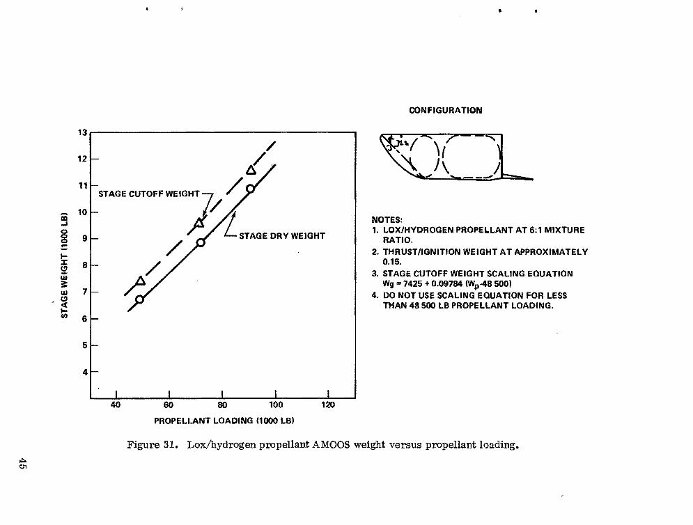
•
iii ...I C)
g c ... :J: 5! w 3: w
-~ ~
13
12
11
10
9
8
7
6
5
4
40 60 80 100 120
PROPELLANT LOADING (1000 LB)
CONFIGURATION
NOTES: 1. LOX/HYDROGEN PROPELLANT AT 6:1 MIXTURE
RATIO. 2. THRUST/IGNITION WEIGHT AT APPROXIMATELY
0.15. 3. STAGE CUTOFF WEIGHT SCALING EQUATION
Wg = 7425 +0.09784 (Wp-48 500) 4. DO NOT USE SCALING EQUATION FOR LESS
THAN 48500 LB PROPELLANT LOADING.
Figure 31. Lox/hydrogen propellant AMOOS weight versus propellant loading. ,j::.. 01
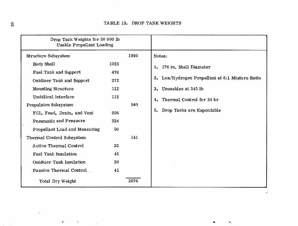
TABLE 13. DROP TANK WEIGHTS ~ """
Drop Tank Weights for 50 000 lb Usable Propellant Loading
Structure Subsystem 1995 Notes:
Body Shell 1023 1. 176 in. Shell Diameter
Fuel Tank and Support 476 2. Lox/Hydrogen Propellant at 6: 1 Mixture Ratio
Oxidizer Tank and Support 272
Mounting Structure 112 3. Unusables at 545 lb
Umbilical Interface 112 4. Thermal Control for 24 hr
Propulsion Subsystem 540 5. Drop Tanks are Expendable
Fill, Feed, Drain, and Vent 256
Pneumatic and Pressure 234
Propellant Load and Measuring 50
Thermal Control Subsystem 141
Active Thermal Control 35
Fuel Tank Insulation 45
Oxidizer Tank Insulation 20
Passive Thermal Control , 41
Total Dry Weight 2676
.. ..

H:>-;J
CD ...I C)
8 :: ~ :E: e" w 3: ~ Z <C... £I. 0 a: c
10
9
8
7
6
5~ 4
3
2
DAOPWEIGHT ~
40 60 80 100 120
PROPELLANT LOADING (1000 LB'
•
CONFIGURATION
/" \". JI
./'
NOTES: 1. 176 IN. SHELL DIAMETER 2. LOX/HYDROGEN PROPELLANT AT6:1 MIXTURE
RATIO 3. THERMAL CONTROL FOR 24 HR. 4. CUTOFF WEIGHT SCALING EQUATION
Wg = 3221 +0.0474 IWp · 50 000' 5. DROP TANKS ARE EXPENDABLE
Figure 32. Lox/hydrogen propellant drop tank weight versus propellant loading.

c. Earth and Space Storable Propellant Stages To compare the performance of the lox/hydrogen propellant stages with
Earth and space storable propellant stages, weight data for lox/RP and N204/ MMH propellants have been estimated for the APOTV and AMOOS concepts. APOTV data are shown in Tables 14 through 17 and in Figures 33 and 34. AMOOS data are shown in Tables 18 through 21 and in Figures 35 and 36.
D. Manned Modules and Emergency Vehicles Weight data for the AMRS (which would serve as a lifeboat type system
and which uses AMOOS type aeromaneuvering) have been developed under study contract with LMSC. Data for a minimum manned module concept to carry four men for 7 days have also been developed. These data may be found in the report LMSC-HREC TR D 496644. The weight data are summarized in Table 22.
The manned module weight data were for use on the AMOOS concept which requires reentry thermal protection. An appropriate manned module weight for use with the APOTV is derived by subtracting the reentry thermal protection. Weight data for the APOTV manned module are also given in Table 22.
It is emphasized that the AMRS and manned module weight data represent very minimal missions, and no payload is included. The AMRS includes no extravehicular activity (EVA) capability, and the manned module includes weights for EVA by two of the crew.
The weight required for the crew module is a significant issue in the selection of an OTV concept. For this reason the manned module weights have been compared with other systems or design data which represent similar hardware. References for this comparison are all manned module data taken from:
1. "Pre-phase A Technical Study for Use of Saturn V, Int 21, and Other Saturn V Derivatives to Determine an Optimum Fourth Stage," NASA Document CR-I03004 Space Tug Volume I of II, February 26, 1971.
2. The Lunar Excursion Module (LEM) data were obtained from the "Apollo Operations Handbook Spacecraft," LMA790-3-LM, dated February 1, 1970.
3. The AMOOS Module Data were obtained from "Applications Study of Aero-Maneuvering Orbit-to-Orbit Shuttle (AMOOS)" LMSC-HREC TR D496644, January 1976.
..
,
..
48

" ..
TABLE 14. APOTV WITH 52 394 lb LOX/RP1 PROPELLANT LOAD
structures
Body Shell 474
Fuel Tank and Supports 146
Oxidizer Tank and Supports 268
Thrust Structure 29
Mounting Structure 100
Payload and Umbilical Interface 263
Total Subsystem Weight
Propulsion
Engine
Feed, Fill, Drain, and Vent
Pneumatic and Pressurization
Hydraulic
Propellant Loading and Measuring
APS
Total Subsystem Weight
Propellant: Lox/RP1 ,j:>. <:s::> Mixture Ratio: 3.2:1
1280
442
256
234
63
50
301
1346
Thermal Control
Active Thermal Control 60
Fuel Tank Insulation 30
Oxidizer Tank Insulation 40
Insulation Purge 72
Passive Thermal Control 41
Total Subsystem Weight 243
Avionics
Guidance, Navigation, and Control 154
Data Management 158
Communication 72
Measuring System 92
Electrical Power and Distribution 410
Rendezvous and Docking 35
Total Subsystem Weight 921
10 Percent Growth 379
Total System Dry Weight 4169
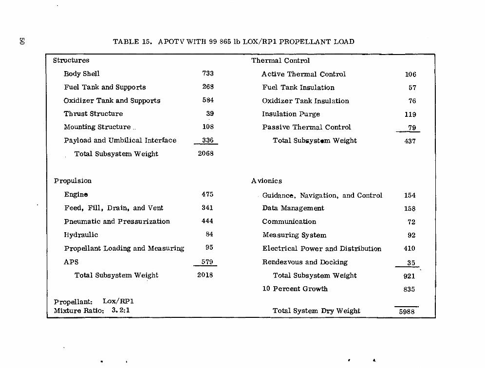
c.n o TABLE 15. APOTV WITH 99 865 lb LOX/RP1 PROPELLANT LOAD
Structures
Body Shell 733
Fuel Tank and Supports 268
Oxidizer Tank and Supports 584
Thrust Structure 39
Mounting Structure __ 108
Payload and Umbilical Interface 336
Total Subsystem Weight 2068
Propulsion
Engine 475
Feed, Fill, Drain, and Vent 341
Pneumatic and Pressurization 444
Hydraulic 84
Propellant Loading and Measuring 95
APS 579
Total Subsystem Weight 2018
Propellant: Lox/RP1 Mixture Ratio: 3. 2: 1
Thermal Control
Active Thermal Control 106
Fuel Tank Insulation 57
Oxidizer Tank Insulation 76
Insulation Purge 119
Passive Thermal Control 79
Total Subsystem Weight 437
Avionics
Guidance, Navigation, and Control 154
Data Management 158
Communication 72
Measuring System 92
Electrical Power and Distribution 410
Rendezvous and Docking 35
Total Subsystem Weight 921
10 Percent Growth 835
Total System Dry Weight 5988
.. • .t,
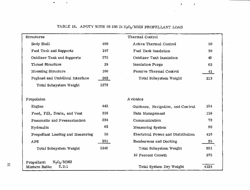
~
TABLE 16. APOTV WITH 56 595 lb N20 4/MMH PROPELLANT LOAD
structures
Body Shell
Fuel Tank and Supports
Oxidizer Tank and Supports
Thrust Structure
Mounting Structure ..
Payload and Umbilical Interface
Total Subsystem Weight
Propulsion
Engine
Feed, Fill, Drain, and Vent
Pneumatic and Pressurization
Hydraulic
Propellant Loading and Measuring
APS
Total Subsystem Weight
Propellant: N20 4/MMH Mixture Ratio: 2.2:1
409
197
275
29
100
263
1273
442
256
234
63
50
301
1346
Thermal Control
Active Thermal Control 50
Fuel Tank Insulation 20
Oxidizer Tank Insulation 40
Insulation Purge 62
Passive Thermal Control 41
Total Subsystem Weight 213
Avionics
Guidance, Navigation, and Control 154
Data Management 158
Communication 72
Measuring System 92
Electrical Power and Distribution 410
Rendezvous and Docking 35
Total Subsystem Weight 921
10 Percent Growth 375
Total System Dry Weight 4128 01

<:Jl N TABLE 17. APOTV WITH 99 865 lb N20 4!l\1l\1H PROPELLANT LOAD
Structures
Body Shell 634
Fuel Tank and Supports 573
Oxidizer Tank and Supports 730
Thrust Structure 39
Mounting Structure .. 108
Payload and Umbilical Interface 336
Total Subsystem Weight 2420
Propulsion
Engine 475
Feed, Fill, Drain, and Vent 341
Pneumatic and Pressurization 444
Hydraulic 84
Propellant Loading and Measuring 95
APS 579
Total Subsystem Weight 2018
Propellant: N20 4!MMH Mixture Ratio: 2.2: 1
Thermal Control
Active Thermal Control 96
Fuel Tank Insulation 38
Oxidizer Tank Insulation 76
Insulation Purge 119
Passive Thermal Control 79
Total Subsystem Weight 408
Avionics
Guidance, NaVigation, and Control 154
Data Management 158
Communication 72
Measuring System 92
Electrical Power and Distribution 410
Rendezvous and Docking 35
Total Subsystem Weight 921
10 Percent Growth 577
Total System Dry Weight 6344
.. ..

CONF IGURA nON
..., /' \ I
J\--""" \
NOTES: 1. LOX/RP PROPELLANT AT 3.2:1 MIXTURE
RATIO 2. THRUST/IGNITION WEIGHT AT APPROXIMATELY
0.15 . 3. STAGE CUTOFF WEIGHT SCALING EQUATION
Wg =4733 +0.04167 (Wp-55 000) 4. DO NOT USE SCALING EQUATION FOR LESS
THAN 55000 LB PROPELLANT LOADING
40 60 80 100 120
PROPELLANT LOADING (1000 LB)
Figure 33. Lox/RP propellant APOTV weight versus propellant loading.
e,., 01

Ql ....
CONF IGURATION
.... ,,\ , I
I
,\
---' "
NOTES: 1. N20 4IMMH .. ROPELLANT AT 2.2:1 MIXTURE
RATIO 2. THRUST/IGNITION WEIGHT AT APPROXIMATELY
0.15 3. STAGE CUTOFF WEIGHT SCALING EQUATION
Wg = 5500 +0.04155 (Wp-56 400) 4. DO NOT USE SCALING EQUATION FOR PROPELLANT
LOADING LESS THAN 56400 LB
40 60 80 100 120
PROPELLANT LOADING (1000 LB)
Figure 34. N20 4/MMH propellant APOTV weight versus propellant loading.
.. ~

TABLE 18.
Structures
Gimbal
Fuel Tank and Support
Oxidizer Tank and Support
Thrust Structure
Mounting Structure
Nose Actuator
Shell Structure
Aft Ring Interface
Total Subsystem Weight
AMOOS WITH 52 391lb LOX/RP1 PROPELLANT LOAD
30
146
268
29
100
100
704
24
1401
Propulsion
Engine 442
Feed, Fill, Drain, and Vent 256
Pneumatic and Press 234
Hydraulic 63
Propellant Load and Measuring 50
APS 500
Total Subsystem Weight 1545
c.n Propellant: Lox/RP1 c.n Mixture Rate: 3.2: 1
Thermal Control
Tank Insulation 78
Purge and Control Sys tern 187
Thermal Protection System 719
Total Subsystem Weight 953
Avionics
Guidance, Navigation, and Control 154
Data Management 158
Communications 72
Measuring Systems 92
Electrical Power and Distribution 410
Rendezvous and Docking 35
Total Subsystem Weight 921
Unbudgeted Contingency 144
10 Percent Contingency 496
Total System Dry Weight 5461
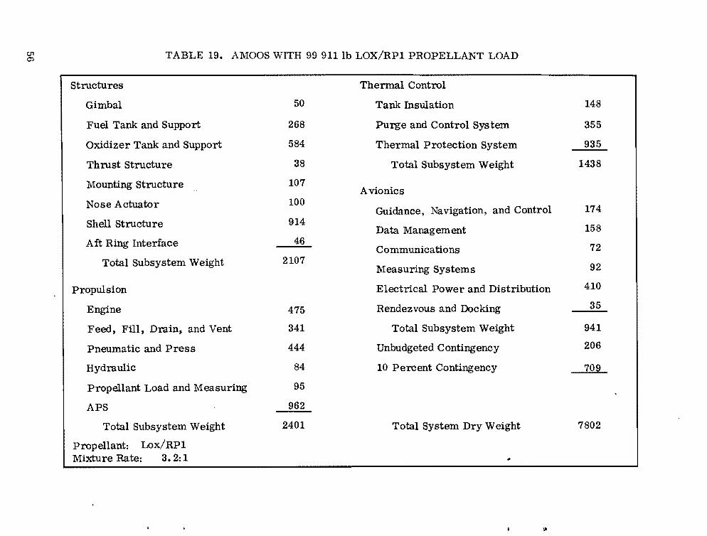
01 TABLE 19. AMOOS WITH 99 911lb LOX/RPI PROPELLANT LOAD<.:l';
Structures
Gimbal
Fuel Tank and Support
Oxidizer Tank and Support
Thrust Structure
Mounting Structure
Nose Actuator
Shell Structure
Aft Ring Interface
Total Subsystem Weight
Propulsion
Engine
Feed, Fill, Drain, and Vent
Pneumatic and Press
Hydraulic
Propellant Load and Measuring
A~
Total Subsystem Weight
Propellant: Lox/RPI Mixture Rate: 3.2: 1
50
268
584
38
107
100
914
46
2107
475
341
444
84
95
9U
2401
Thermal Control
Tank Insulation 148
Purge and Control System 355
Thermal Protection System 935
Total Subsystem Weight 1438
Avionics
Guidance, Navigation, and Control 174
Data Management 158
Communications 72
Measuring Systems 92
Electrical Power and Distribution 410
Rendezvous and Docking 35
Total Subsystem Weight 941
Unbudgeted Contingency 206
10 Percent Contingency 709
Total System Dry Weight 7802
~

TABLE 20. AMOOS WITH 52 412lb N20 4/MMH PROPELLANT LOAD
Structures Thennal Control
Gimbal 30 Tank Insulation 26
Fuel Tank and Support 197 Purge and Control System 62
Oxidizer Tank and Support 275 Thermal Protection System 682
Thrust Structure 29 Total Subsystem Weight 770
Mounting Structure 100 Avionics
Nose Actuator 100 Guidance, Navigation, and Control 154
Shell Structure 667 Data Management 158
Aft Ring Interface 24 Communications 72
Total Subsystem Weight 1422 Measuring Systems 92
Propulsion Electrical Power and Distribution 410
Engine 442 Rendezvous and Docking 35
Feed, Fill, Drain, and Vent 256 Total Subsystem Weight 921
Pneumatic and Press 234 Unbudgeted Contingency 140
Hydraulic 63 10 Percent Contingency 480
Propellant Load and Measuring 50
APS 500
Total Subsystem Weight 1545 Total System Dry Weight 5278
01 ....::)
propellant: N20 4/MMH Mixture Rate: 2.2:1

00 c:.n TABLE 21. AMOOS WITH 99 865 lb N20 4/MMH PROPELLANT LOAD
Structures
Gimbal
Fuel Tank and Support
Oxidizer Tank and Support
Thrust Structure
Mounting Structure
Nose Actuator
Shell Structure
Aft Ring Interface
Total Subsystem Weight
Propulsion
Engine
Feed, Fill, Drain, and Vent
Pneumatic and Press
HydrauliC
Propellant Load and Measuring
APS
Total Subsystem Weight
Propellant: N20 4/MMH Mixture Rate: 2.2:1
40
573
730
39
108
100
1055
60
2705
475
341
444
84
95
961
2400
Thermal Control
Tank Insulation 49
Purge and Control System 118
Thermal Protection System 1078
Total Subsystem Weight 1245
Avionics
Guidance, Navigation, and Control 174
Data Management 158
Communications 72
Measuring Systems 92
Electrical Power and Distribution 410
Rendezvous and Docking 35
Total Subsystem Weight 941
Unbudgeted Contingency 219
10 Percent Contingency 751
Total System Dry Weight 8260
...
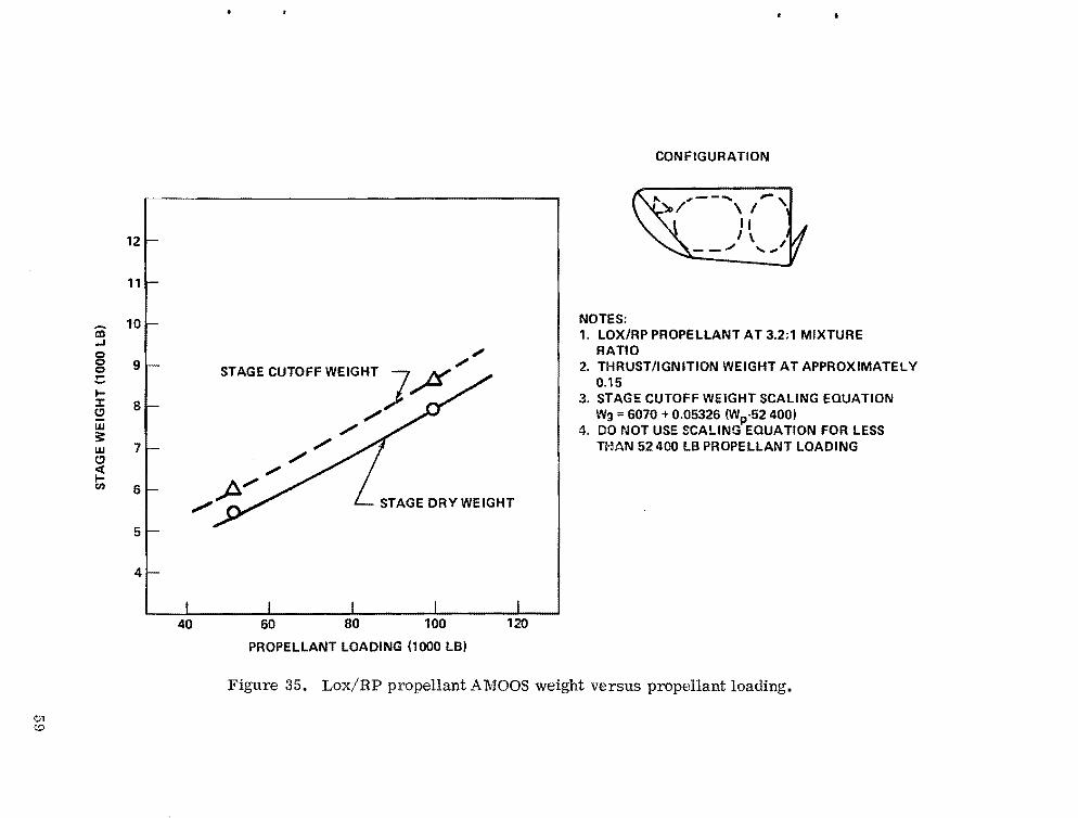
01 ~
iii ....I Q Q Q
!::: ... :r: 0 w 3: w 0 «... CI)
12
11
10
9
8
7
6
I 5
4
"., STAGE CUTOFF WEIGHT J~
" " " " /p//-/ L- STAGE DRY WEIGHT
40 60 80 100 120
PROPELLANT LOADING (1000 lB)
NOTES:
CONFIGURATION
... .,.-- .... -,)0/ \1
II J \
--"'" .... ""
1. LOX/RP PROPELLANT AT 3.2:1 MIXTURE RATIO
2. THRUST/IGNITION WEIGHT AT APPROXIMATELY 0.15
3. STAGE CUTOFF WEIGHT SCALING EQUATION Wg =6070 +0.05326 (Wp.52400)
4. DO rJOT USE SCALING EQUATION FOR LESS THAN 52400 lB PROPELLANT LOADING
Figure 35. Lox/RP propellant AMOOS weight versus propellant loading.

0') o
-al ...I
8 0 !: I::c (!I
w ~ w (!I « ICI.I
12
11
10
9
8
7
6
5
4
/' STAGE CUTOFF WEIGH],/,;~
/ /
"IX/ /' L- STAGE DRY WEIGHT
0
40 60 80 100 120
PROPELLANT LOADING (1000 LB)
CONFIGURATION
"".-- -, .-.- .... , .... , I ,I' \ _ .... J \/
l I' .I \- -_/
NOTES: 1. N20 4 /MMH PROPELLANT AT 2.2:1 MIXTURE
RATIO 2. THRUST/IGNITION WEIGHT AT APPROXIMATELY
0.15 3. STAGE CUTOFF WEIGHT SCALING EQUATION
Wg = 5900 +0.06723 (Wp·S2400) 4. DO NOT USE SCALING EQUATION FOR PROPELLANT
LOADING LESS THAN 52400 LB
Figure 36. N20 4/l\:IMH propellant AMOOS weight versus propellant loading.
..

TABLE 22. WEIGHT SUMMARY - MANNED CARRIERS (WEIGHT IN lb)
Vehicle Element AMRSa
Man Modulea
(A MOOS Configuration)
Man Module (APOTV
Configuration)
Crew and Supplies 1664 2873 2873
Structures 1542 1671 1671
Thermal Protection 395 335 N/A
Propulsion 867 N/A N/A
Avionics 1065 725 725
EVA Equipment N/A 372 372
Miscellaneous 00 40 40
10 Percent Growth 477- 604- 569-Total Dry Weight 6010 6620 6250
Propellant 6500 N/A N/A
a. Reference LMSC-HREC TR D 496644.
A comparison with the data being used is shown in Figure 37. As can be seen, the minimum module weight for four men for 7 days is approximately 6500 lb. This is also the approximate weight needed for crew transfer to geo- . synchronous orbit and return to low Earth orbit. These data are not necessarily applicable for either the crew transfer or the sortie missions, and the data which follow in Paragraph E should be used for the crew transfer and sortie mission cases.
E. Manned Sortie Mission Weights Previous OTV study as well as other NASA planning studies indicate the
desirability for man-sortie mission capability. The data given in Paragraph D may be applicable for short sortie missions where shielding is not important.
61

~
1Il t:.n -1 ~
1:r: L!J
w :3:
16320 12 MEN
I Ll~r:l~
12m:m
10Zin:l
Bi1~1B
6r." "'3u.:.!
~m:m
2Z~a
B 8
~ tiEN
2 HEN
AMOOS MANNED MODUL!
LEM DATA CORRECTED
J8 2H NO. Dr DAYS
Figure 37. Crew module weight versus man days.
Also, the data assume rather large crew modules. The data which follow in this section were derived to determine the effects of stay time on crew module size and to incorporate current shielding requirements.
Table 23 shows the manned sortie mission volume requirements for a four-man crew for mission times of 2, 7, 14, 21, and 30 days. Table 24 shows the corresponding weight which is required for these missions. No weight is included for the external OTV shell because it is assumed that the shell would contribute to the radiation shield and that the shielding weight would be reduced by the OTV shell weight. This should be satisfactory for the longer missions but may be marginal for shorter missions. The weight values are approximately 20 percent lower than previously given. The OTV power supply would not be designed to accommodate the longer missions. The manned module would be equipped with a power system using fuel cells and solar arrays. This system would supply OTV power during the long mission.
62
..
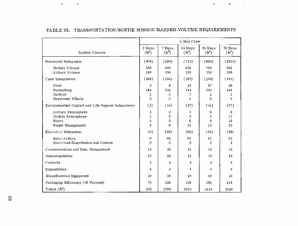
TABLE 23. TRANSPORTATION/SORTIE MISSION MANNED VOLUME REQUIREMENTS
4 Man Crew
2 Days 7 Days 14 Days 21 Days 30 Days System Closure (ft3) ( ft3) ( ft3) ( ft3) ( ft3)
Structural Subsystem ( 308) ( 598) ( 754) ( 934) ( 1054)
:\1odule Volume 158 448 604 784 904 Airlock Volume 150 150 150 150 150
Crew Subsystems ( 150) ( 156) ( 167) ( 183) ( 191)
Food 3 9 18 27 38 Furnishing 144 144 144 144 144 :'ledical 1 1 1 1 1 Personnel Effects 2 2 4 6 8
Envi ronmental Control and Life Support Subsystems ( 5) ( 14) ( 27) ( 41) (57)
Ai rlock Atmosphere 1 2 4 6 8 :'lodule Atmosphere 1 3 5 8 11 Water 1 3 6 9 13 Waste Management 2 6 12 18 25
E lectriu, I Subsystem ( 6) (66) (66) ( 66) ( 66)
Sola r Arrays - 64 64 64 64 Electrical Distribution and Control 6 2 2 2 2
Communication and Data Management 12 12 14 14 14
Instrumentation 10 13 18 18 18
Controls 4 4 4 4 4
Expendables 4 4 4 4 4
Miscellaneous Equipment 10 10 10 10 10
Packaging Efficiency (85 Percent) 76 131 159 191 212
Totals (ft3) 585 1008 1223 1414 1630
(J') C;:>
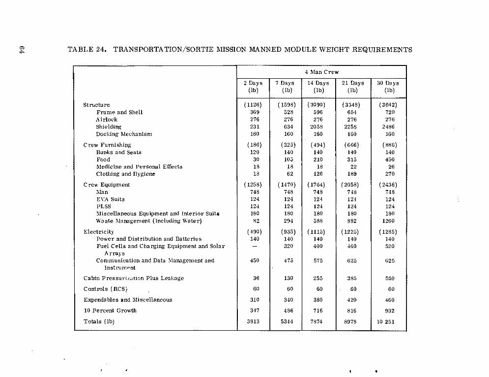
0') TABLE 24. TRANSPORTATION/SORTIE MISSION MANNED MODULE WEIGHT REQUIREMENTSIl'>
Structure Frame and Shell Airlock Shielding Docking Mechanism
Crew Furnishing Bunks and Seats Food l\ledicine and Personal Effects Clothing and Hygiene
Crew Equipment l\Ian EVA Suits PLSS Miscellaneous Equipment and Interior Suits Waste Management (Including Water)
Electricity Power and Distribution and Batteries Fuel Cells and Charging Equipment and Solar
Arrays Communication and Data ::'Ilanagement and
lnst r'llrr.f>nt
Cabin Pressuril.~ltion Plus Leakage
Controls (RCS)
Expendables and Miscellaneous
10 Percent Grov.1h
Totals (lb)
4 Man Crew
2 Days (lb)
7 Days (lb)
14 Days (lb)
21 Days ( lb)
30 Days (lb)
I
( 1126) 369 276 231 160
( 186) 120 30 18 18
( 1258) 748 124 124 180 82
( 490) 140 -
450
36
60
310
347
3813
(1598) 528 276 634 160
( 325) 140 105 18 62
( 1470) 748 124 124 180 294
(935) 140 320
475
130
60
340
486
5344
( 3090) 596 276
2058 160
(494) 140 210
18 126
( 17(4) 748 124 124 180 588
( 1115) 140 400
575
255
60
380
716
7874
( 3348) 654 276
2258 160
( (66) 140 315
22 189
( 2058) 748 124 124 180 882
( 1225) 140 460
625
385
60
420
816
8978
( 3(42) 720 276
2486 160
( 886) 140 450
26 270
( 2436) 748 124 124 180
1260
( 1285) 140 520
625
550
60
460
932
10 251
•

The data in this section and in Section D were reviewed, and the weight data shown in Table 25 were selected for further OTV analysis.
TABLE 25. WEIGHTS REQUIRED FOR CREW TRANSFER AND SORTIE MISSIONS
Crew Mission Weight (lb) Mission Size DUration Round Tripa
Crew Transfer 4 12
N/A N/A
5000 12000b
Man-Sorties 4 4 4 4
7 14 21 30
6400 9500
11 000 12 400
a. Does not include any mission equipment weight b. Reference LMSC 1977 AMOOS Study
Figure 38 shows the data given in Tables 23, 24, and 25 in curve form. As can be seen, the four-man sortie mission weight required is rather linear with mission time. The volume also increases linearly after approximately 7 days. Also referenced on the chart are crew transfer volume requirements as determined by LMSC in the 1977 AMOOS Applications Study. The weight required for a four-man 30 day sortie is approximately the same as that required for a 12-man crew transfer mission.
F. OTV Propellant Loading - Propellant Weight Required To say that TIthe sizing of an OTV for a particular Shuttle capability is
difficultn is a gross understatement. The propellant loading required for a particular Shuttle capability is determined by:
1. The payload weight
Delivery only or
Round trip or
Combination delivery and round trip
65

0') 0')
18
16
14
-ID 12.... 8 0 !: I
10 ::J: C)
w 3: 8 w .... :::> Q 0 6::E
41
21
0
WEIGHT VOLUME 18
16
REFERENCE CREW SIZE (TRANSFER ONLY) 14 I 4-MAN SORTIE
rf) I 12
4-MAN SORTIE u.
8 !: w 10 r / REFERENCE CREW (SIZE)::E :::> TRANSFER ONLY .... 0 > 8 w .... :::> Q0 6::E
~ REFERENCE LEM 4
2
·....,SC 1977 J I *LMSC 1971
5 10 15 20 25 30 0 5 10 15 20 25
MISSION DURAtiON (DAYS) MISSION DURATION (DAYS)
Figure 38. Four-man sortie mission module (reference crew transfer module) weight and volume requirement.
..
30
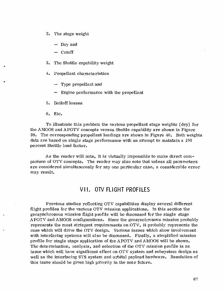
2. The stage weight
Dry and
Cutoff
3. The Shuttle capability weight
4. Propellant characteristics
Type propellant and
Engine performance with the propellant
5. Boiloff losses
6. Etc.
To illustrate this problem the various propellant stage weights (dry) for the AMOOS and APOTV concepts versus Shuttle capability are shown in Figure 39. The corresponding propellant loadings are shown in Figure 40. Both weights data are based on single stage performance with an attempt to maintain a 100 percent Shuttle load factor.
As the reader will note, it is virtually impossible to make direct comparison of OTV concepts. The reader may also note that unless all parameters are considered simultaneously for anyone particular case, a considerable error may result.
VII. OTV FLIGHT PROFILES
Previous studies reflecting OTV capabilities display several different flight profiles for the various OTV mission applications. In this section the geosynchronous mission flight profile will be discussed for the Single stage APOTV and AMOOS configurations. Since the geosynchronous mission probably represents the most stringent requirements on OTV, it probably represents the case which will drive the OTV design. Various issues which show involvement with interfacing systems will also be discussed. Finally, a simplified mission profile for single stage application of the APOTV and AMOOS will be shown. The determination, analysis, and selection of the OTV mission profile is an issue which will have significant effect on OTV system and sUbsystem design as well as the interfacing STS system and orbital payload hardware. Resolution of this issue should be given high priority in the near future.
67

en 00
a:I .... g 0.... l:I: c:J w:: w c:J <t l(I)
>a:: C
AMOOS APOTV 20~i----------------------------------' ~,,-------------------------------~
10 10 9
a:I 9
8 .... 8 0
1 0 70.... 6 - 6I
:I: 5 c:J 5
w:: 4 w 4
c:J <t I(I)
3 > 3 a:: C
21 2
1 LI______~____~_______L______L_____~~____~ 1 L'______~____~_______L______~______L______J
60 70 80 90 100 110 120 60 70 80 90 100 110 120
SHUTTLE CAPABILITY (1000 LB) SHUTTLE CAPABILITY 11000 LB)
Figure 39. weights versus Shuttle capability.
,. III
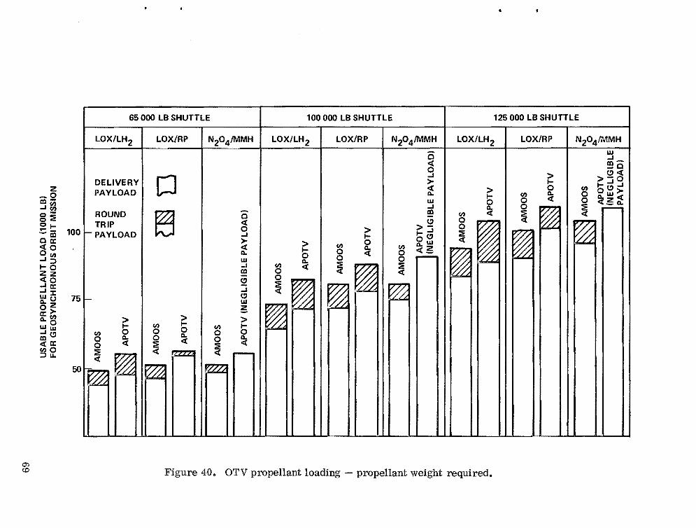
65 000 LB SHUTTLE 125000 LB SHUTTLE 100000 LB SHUTTLE
LOX/LH2 LOX/RP N20 4IMMH LOX/LH2 LOX/RP N20 41i'JlMHLOX/LH2 1 LOX/RP 1N20 4IMMH
DELIVERY z PAYLOAD LJ_0
co..J~ 0 -ROUND 00:::E «TRIP01 0"'" -co 100 ...I~PAYLOADOa:: >«0 «
0..Oen W..J::::l ..J1-0 coZz
«0 CJ ...I a::
...I..JJ: CJWo 75 WO-z g0>a:: (I)
0.. 0 > >> I-enI- en I-Ww 00 0 0en 0 0..~CJ 0..0 00 0« «««a:: :::E0enO ~ .-
~ ::::lLl.
5O~~~i1
-0 « o ...I > « 0.. w ...I co
en 0
> I 0 0.. «
(I)
0 0
> I 0 0.. «
en 0 0 :::E «
CJ >1-...1 oCJ o..w «g n
~~ ~~ ~ ~
W ...I co_0 CJ«> >-0I 1-...1...10 (I) OCJ>> (I) 0.. 0I ~w««0 0 go..0
0.. :::E .-(I) « «
~~~ ~~
O'l <:.0 Figure 40. OTV propellant loading - propellant weight required.
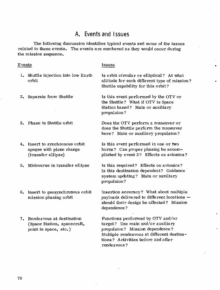
A. Events and Issues The following discussion identifies typical events and some of the issues
related to these events. The events are numbered as they would occur during the mission sequence.
Events
1. Shuttle injection into low Earth orbit
2. Separate from Shuttle
3. Phase in Shuttle orbit
4. Insert to synchronous orbit apogee with plane change (transfer ellipse)
5. Midcourse in transfer ellipse
6. Insert to geosynchronous orbit mission phasing orbit
7. Rendezvous at destination (Space Station, spacecraft, point in space, etc.)
Issues ..
Is orbit circular or elliptical? At what . altitude for each different type of mission? Shuttle capability for this orbit?
Is this event performed by the OTV or the Shuttle? What if OTV is Space Station based? Main or auxiliary propulsion?
Does the OTV perform a maneuver or does the Shuttle perform the maneuver here? Main or auxiliary propulsion?
Is this event performed in one or two burns? Can proper phasing be accomplished by event 3? Effects on avionics?
Is this required? Effects on avionics? Is this destination dependent? Guidance· system updating? Main or auxiliary propulsion?
Insertion accuracy? What about multiple payloads delivered to different locations should their design be affected? Mission dependence?
Functions performed by OTV and/or target? Use main and/or auxiliary propulsion? Mission dependence? Multiple rendezvous at different destinations? Activities before and after rendezvous?
70

Events
8. Deliver payload
or
9. Dock
10. On orbit stay
11. Separate from target or depart location
12. Move to next target
or 13. Insert to low Earth orbit
transfer ellipse
14. Midcourse correction
15. Low Earth orbit injection burn (APOTV only)
or
16. Low Earth orbit aeromaneuver (AMaaS only)
17. Raise perigee (AMaaS only)
Issues
Positioning accuracy? Check out payload? Multiple payloads?
Docking peculiar hardware and/or avionics carried on target or OTV? Number of dockings per mission?
Length of time? Functions to be performed while on orbit? Effects on Shuttle waiting in low Earth orbit? Boiloff? Effects on subsystems?
Guidance update? Time phasing? Is total orbit mission complete?
Phasing? Main or auxiliary propulsion?
Guidance update? Time phasing? What portion of plane change to make propulsively (AMaaS only)? Number of burns?
Entry corridor? Altitude and longitude requirement? Subsystem effects? Timing of correction? Guidance updating?
Number of burns? Altitude error? Inclination error? Phasing? Period in high radiation environment?
Large Reaction Control System (RCS) required. Number of passes? Communications during maneuver? Plane change to perform? Payload protection? Apogee altitude? Minimum altitude?
Initiate by timer or by guidance/reference system? Main or auxiliary propulsion? Communications?
71

Events Issues
18. Insert to Shuttle phasing orbit Shuttle position? Guidance update? Ground support? Maneuver by Shuttle or OTV? What about Space Station case? Main or auxiliary engines?
19. Orbit trim maneuvers Shuttle or OTV?
20. Burn for Shuttle rendezvous Shuttle or OTV? Main or auxiliary • orbit propulsion? Space Station case?
21. Rendezvous burn Burn by Shuttle or OTV? Functions by Shuttle or OTV? Space Station case?
22. Shuttle docking and loading OTV Hardware? Shuttle hardware? AMOOS temperature? Residual(s) disposal? Tank insulation protection? Tank pressurization? Load and attach? Transfer man to Shuttle cabin? Safety check?
Resolution of the OTV flight profile and event sequencing requires simultaneous considerations of interfacing space hardware and the Shuttle or Space Station functions as well as some type of standardized space operations procedures. The events and associated issues previously given are only typical of the situations which could arise. Practical solutions to these issues will certainly have significant influence on the eventual OTV design.
B. Single Stage APOTV Figure 41 shows a simplified flight profile for the APOTV. Events are
numbered with explanation given in Table 26. This profile was determined in the past high performance Tug studies. Whether this profile would still be applicable or optimum for APOTV application under the current mission planning is uncertain.
C. Single Stage AMOOS Figure 42 shows a simplified flight profile for the AMOOS. Events are
numbered with explanation given in Table 27.
72
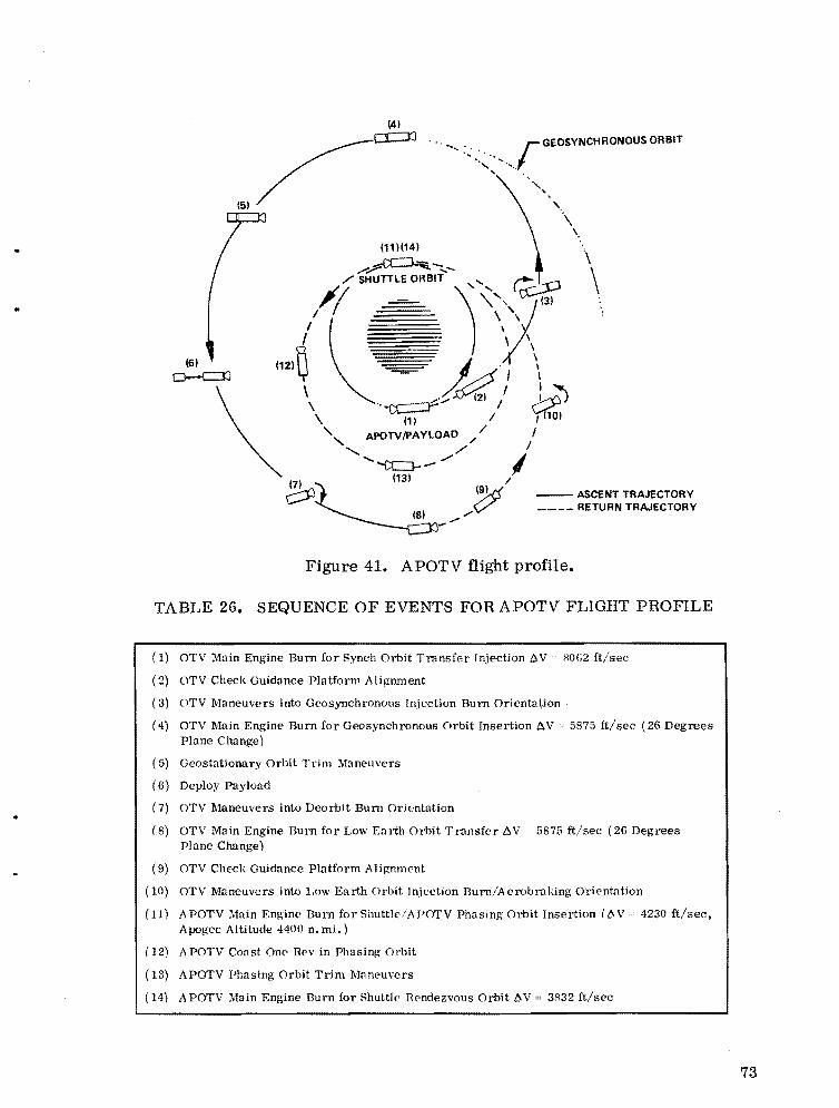
....... ::.<··~ ... rGEOSYNCHRONOUSORBIT
, .
'\ \
(1111141
.......~"'liiE.-:..._ /' SHUTTLE ORBIT ", ~ \
• ,// ~ )\'\)'" '.
\
,6' "21~ ( ~ _ . \ \ o--c::::!l Y ~ -=- I \
\ (1) / I 10)
" APOTVIPAYLOAD / / I '- /' I
'--cc:J-./ I (131 - /
- ASCENT TRAJECTORY ~=t ~ ____ RETURN TRAJECTORY
~-,,/
Figure 41. APOTV flight profile.
TABLE 26. SEQUENCE OF EVENTS FOR APOTV FLIGHT PROFILE
(1) OTV Main Engine Burn for Synch Orbit Transfer Injection D V ~ ?l062 ft/sec
(2) OTV Check Guidance Platform Alignment
(3) OTV Maneuvers into Geosynchronous Injection Burn Orientation
(4) OTV Main Engine Burn for Geosynchronous Orbit Insertion f:,V 5875 rt/sec (26 Degrees Plane Change)
(5) Geostationary Orbit Trim Maneuvers
(6) Deploy Payload
(7) OTV Maneuvers into Deorbit Burn Orientation
(8) OTV Main Engine Burn for Low Eo. rth Orbit Transfer f:,V ~ 5875 ft/sec (26 Degrees Plane Change)
(9) OTV Check Guidance Platform Alignmcnt
(10) OTV Maneuvers into Low Earth Orbit Injection Burn/Aerobraking Orientation
(11) APOT V Main Engine Burn for Shuttle/APOTV Phasing Orbit Insertion «(). V 4230 ft/sec, Apogee Altitude 4400 n. mi.)
(12) APOTV Coast One Rev in Phasing Orbit
(13) APOTV Phasing Orbit Trim Maneuvers
(14) APOTV Main Engine Burn for Shuttle Ilendezvous Orbit ()..V 3832 ft!sec
73

74
GEOSYNCHRONOUS ORBIT , ........ _
.-' /
/ 5 /
c:.:::J:J I
/ I
I . ~ j ."'.. b6' ·... 0·,. )3o c:::ll 1",
\
\ .. i\ .. ;..... l./ \ ''-oc:=r~ J:;:?
1 I
7 AMOTVIPAVlOAD)
c::::ll I
~-bJ-""/Y
_ ASCENT TRAJECTORY ---- RETURN TRAJECTORV
Figure 42. AMOOS flight profile.
TABLE 27. SEQUENCE OF EVENTS FOR AMOOS FLIGHT PROFILE
(1) OTV Main Engine Burn for Synch Orbit Transfer Injection 6 V HOG2 ftlsec
(2) OTV Check Guidance Platform Alignment
(3) OTV Maneuvers into Geosynchronous Injection Durn Orientation
(4) OTV Main Engine Burn for Geosynchronous Orbit Insertion l!J.V ~ GH75 ft/sec (26 Degrees Plane Change)
(5) Geostationary Orbit Trim Maneuvers
(6) Deploy Payload
(7) OTV Maneuvers into Deorbit Burn Orientation
(8) OTV Main Engine Durn for Low f:arth Orbit Transfer l!J. V 5H75 ft/eec (26 Degrees Plane Change)
(9) OTV Check Guidance Platform Alignment
(10) OTV Maneuvers into Low Earth Orbit Injection Durn/Aerobraking Orientation
(11) AMOTV Performs Aerobraking Maneuver (Minimum Altitude = 37 n. mi.) Apogee Altitude = 388 n. mi. ± 54
(12) AMOTV Coast One Rev in Phasing Orbit
(13) AMOTV Phasing Orbit Trim and Perigee Raise Maneuver D.V 220 ft/sec
(14) AMOTV Main Engine Durn for Shuttle Hendezvous Orbit l!J. V = 400 ft/sec
II
•
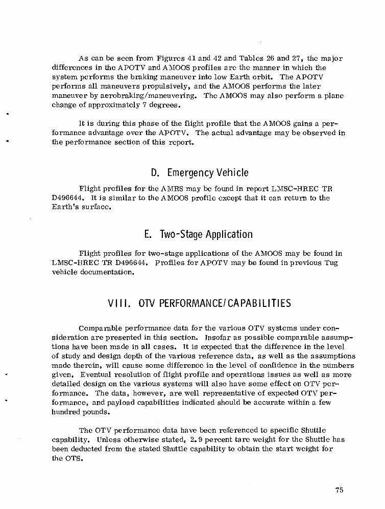
As can be seen from Figures 41 and 42 and Tables 26 and 27, the major differences in the APOTV and AMOOS profiles are the manner in which the system performs the braking maneuver into low Earth orbit. The APOTV performs all maneuvers propulsively, and the AMOOS performs the later maneuver by aerobraking/maneuvering. The AMOOS may also perform a plane change of approximately 7 degrees.
It is during this phase of the flight profile that the AMOOS gains a performance advantage over the APOTV. The actual advantage may be observed in the performance section of this report.
D. Emergency Vehicle Flight profiles for the AMRS may be found in report LMSC-HREC TR
D496644. It is similar to the AMOOS profile except that it can return to the Earth fS surface.
E. Two-Stage Application
Flight profiles for two-stage applications of the AMOOS may be found in LMSC-HREC TR D496644. Profiles for APOTV may be found in previous Tug vehicle documentation.
VIII. OTV PERFORMANCE/CAPABILITIES
Comparable performance data for the various OTV systems under consideration are presented in this section. Insofar as possible comparable assumptions have been made in all cases. It is expected that the difference in the level of study and design depth of the various reference data, as well as the assumptions made therein, will cause some difference in the level of confidence in the numbers given. Eventual resolution of flight profile and operations issues as well as more detailed design on the various systems will also have some effect on OTV performance. The data, however, are well representative of expected OTV performance, and payload capabilities indicated should be accurate within a few hundred pounds.
The OTV performance data have been referenced to specific Shuttle capability. Unless otherwise stated, 2.9 percent tare weight for the Shuttle has been deducted from the stated Shuttle capability to obtain the start weight for the OTS.
75

For the most part the lox/hydrogen APOTV and AMOOS reference data were based on an engine I of 456.5 sec (HL 10 Category IIB engine), and the
sp data given here are primarily for this engine performance. Advanced engines are expected to provide approximately 470 sec I • A comparison of the 456.5 and 470 sec performance will be shown. sp
The reader should note the I values shown for the storable and solid sp
systems are slightly optimistic. This was intentional to ensure that the competitiveness of these systems be maximized.
A. OlV Single Stage Capabilities Comparable payload capabilities for lox/hydrogen, lox/HP, and N20 4/
MNIH propellants are shown for the APOTV and AMOOS concepts in Figure 43. Capabilities for 65 000, 100 000, and 125 000 lb Shuttle capabilities are shown. As indicated, the payload capabilities for lox/HP and N20 4/MNIH are very low or negligible for the APOTV concept. Parametric data for each case are shown in Figure 44.
B. Staging Effects on OlV Capability - One Shuttle Launch Single stage, dual stage, and drop tank plus stage for a 100 000 lb Shuttle
capability are shown in Figure 45. It should be noted that a 456.5 sec I was sp
used in this case. Even though the drop tanks were expended in this case, the capability is only slightly greater than the dual stage case. The dual stage and the drop tank cases shown here would probably require cargo bay lengths greater than 60 ft.
C. Capability Comparison for One- and Two-Shuttle Launches Figure 46 shows capabilities for the 65 000 and 100 000 lb Shuttle capa
bilities for one- and two-Shuttle launches. As noted, the payload for the twostage case must be split and carried on each of the two Shuttle launches. As may be expected, the major problem with multiple Shuttle launches is maintaining a high Shuttle load factor. This creates the problem of dividing the payload for the two-launch case. Since the stages are designed for single launch, they must be offloaded.
..
76

-::J -::J
REQUIREMENT I::. ::.. : :.=~~ DEUVERY ONLY D ROUNDTRIP ~
65000 LB SHUTTLE 100,000 SHUTTLE 125000 LB SHUTTLE I ~ w
30 I LOX/HYD LOX/RP IN20 4IMMH LOX/HYD I LOX/RP IN204IMMN I LOX/HY·D I LOX/RP I N20 4/MMN ~. _I W 0
'iii "'" § !: o g > ~20
~ o a: :J: o Z
~ ~ 10 ~
CI')
~ g ~1~ ~ ~ ~ ~ ~ ~ ~ U ~ll~ L~1~ ~J ~ ~ i8 0
-~----~ ~--.-~ ~ ---~ -!- ~ ~---~ ~ g -!---g -!-- g- j~ At(
O'KLlr'.'K"r',IILAI'D,rLI.LOJW'4'CO Ke,..-" 'Lor" I"IK<"KC' .'c.
NOTES:
G) SINGLE STAGE
® LOX/HYD 0456.5 SEC Isp
LOX/RP 0 380 SEC Isp
N204IMMH " 349 SEC Isp
® NO LENGTH CONSTRAINTS CONSIDERED
Figure 43. Single stage OTV performance comparison.
30 DAY ROUND TRIP 1500- 2500 LB. eQUIP.'
1500 LB. eQUIP.)

-J 00
APOTV - LOX/HYDROGEN 32~i------------------------------------~
_28 GIl ..l
824 S 020 w a: w >16 ~ w 0 12o c(
g 8 >~
4
SHUTTLE CAR
l i~OOO LSI
"IJ0<0
125~ "0~
l,P = 45$.5 SEC
' 2 (t,. 100\" '\{ ~"'(t
• t.-~
4 0 1
:'< , .., MAXIMUM
'\Y" ROUND
TRIPO~'______________________________________~
;::A=M=O=O=S~__L_O_X_/H_Y_D_R_O__G_EN__________________--, ~i
_28.125 :g
"4 "LOAO2 .. .,~.,. ISp = 456.5 SEC
..l
8 24
S 020 w a:
216 ..l w 012 o c(
g 8 >~ ..
4 6 "/~II~O 8 10 (1000L8
)
12 14
SHUTTLE CAPABILITV
11000 LBI
MAXIMUM ROUNDTRIP CAPABILITY
O,L__________________________________________~
AI!Q.Dt LOXIRP 32ri----------------------~
_28 GIl .....
§ 24.. 020 w a: w > 16 ~ w 0
12o « g 8 >c( Q.
4
~ "<o
111.0 I,:..O~
liP = 380 SEC
I 't)~)': 2 (~~~i
(1'0
o L'_____________--'
~-LOX/RP 32ri====~----------------~
iij28 GIl ..l 024 8.. 020 w a: ~ 16 ~ w 0 12 o « g 8 >« Q. 4
Isp =380 SEC
"4"(.040
It) 0 2 1i~"'''/~I1,," N ".<;0(,tlA.,. .. • '6 -~L_ 8 .8 10...
TRIPOL'______________~
~ - N20..' MMH32.
_28 GIl ..J
§ 24 .020 w a: w > 16 ~ w 012 o c(
g 8 >c( Q. 4
liP = 349 SEC
NEGLIGIBLE CAPABILITY
o L'_________....
~-N204/MMH32 i
iii 28 ..J o ~ 24
o w 20 a: w ::= 16 ..l w o 0 12 c( o ~ 8 c( Q.
4
Isp =349 SEC
SHUTTLE CAP.
1 11000-~a'
Ii~,. I-(O..q 11o",,!/~/,; 0
III~ -"'Q1.""e"0 ~\~ 2 VJ8 . ..
MAXIMUM
oI ROUND TRIP
Figure 44. Single stage OTV performance/capabilities.
NOTE!i: 1 SHUTTLE TARE
02.9% 2 THRUST/IGNITION
WEIGHT.0.1S 3 NO HEAT SHIELD
ASSUMED FOR AMOOS RETURNED PAVLOAD IAPPROX. SHIELD
WEIGHT IS 8 '" OF PAYLOAD C!.PABILlTV
..

--1 ~
a:I ...J
g Il: (!)
w :it o <t o ...J ><t Q..
en ::::> o z o 0:: l: (,) Z > ~ u.s (!)
REOUIREMENT [= - -
SINGLE STAGE DROP TANK
DUAL STAGE PLUS STAGE
32 ll------------~--------~--t_----------~
28
24
20 -I
16 -I
12 1 n >I
8 ..,I I 0 a... <t
h 4
0
r-l
enl 0
I 0
~ 1_1_1 ~ L-......J
a... «
en 0 0 :!! <t
~ o Q.. <t
en o o ~ <t >
0:: u.s 2! ....I u.s o
o z =>2:: 00:: 0:: ....
NOTES: CD LOX/HYDROGEN @
456.5 SEC Isp @NOCARGO BAY LENGTH
RESTRAINTS. (AMOOS SINGLE STAGE PRESENTS LENGTH PROBLEM· ALL DUAL STAGE & DROP TANK CONFIG. EXCEED 60FT CARGO BAY LENGTH)
GDSTAGESANDPAYLOAD LAUNCHED ON SAME SHUTTLE
@)SHUTTLE TARE WEIGHT @2,900 LB
@DROPTANKS EXPENDED· ALL OTHER STAGES RECOVERED/REUSED
o DELIVERY ONLY
~ ROUND TRIP
Figure 45. Staging effects for OTV systems (100 000 lb Shuttle capability).

00 o
a.oJ SINGLE STAGE
~ 70 651( SHUTTLE 1001( SHUTTLE
>I
60J DELIVERY ONLY I~
0iii « CL « u Q«
d0 .oJ 50> UNCERTAINTY«. CL I-iii a: 40
fZd0 II) ROUND TRIP :;) 0 Z 0 30 ------ ------ ------ - --cij--a: :I: 0 U 0 Z "':
> .. --- -- .. ---- - --=t-.II)
> II) >0 020 I 0 I-w 0 0(!) CL :: CL « '" '" --_ ...... -. 10
I
DUAL SHUTTLES
'TWO STAGE CSEE 2'
651( SHUTTLE 1001( SHUTTLE
I (II
0 0 :E '"
~ 0
CIt ~ g :E
'"
NOTES:
<D lOX/HYDROGEN PROPELLANT @ 456.5 SEC Isp
~STAGES USED IN TWO STAGE APPLICATIONS ARE SIZED fOR SINGLE STAGE APPLICATIONS (SEEla.SI
~WEIGHT OF TWO STAGE SYSTEMS AND PAYLOAD MAY EXCEED CAPABILITY OF TWO SHUTTlE LAUNCHES. STAGES WOULD BE Off LOADED TO MATCH TWO SHUTTLE CAPABILITY. (SEE 4)
@PAYLOADMUSTBE SPLIT ON EACH OF TWO SHUTTLES OR CARRIED ON A THIRD SHOTTLE.
<I) REQUIRES NEAR SIMUL TANEOUS SHUTTlE LAUNCH AND OR LOW EARTH ORBIT SPACE STATION ASSY AND FUEL·BOILOH REPLENISHMENT.
ELEMENT DELIVERY
30 DAY ROUND TRIP
: :1- 1!>OIl - 2500 L8 EGUIP..
/10........ 7 DAY ROUND TRIP t!JOO t 8. EOUIP J
o 1«1 t<c1 """ 1«.
REOUIREMENT t::.~ ~-::- ::-=- -~J
Figure 46. Single/dual Shuttle performance/capabilities.
...

D.. Expendable Solid Boosters for Multiple Shuttle Launches Expendable solid boosters may offer attractive options for obtaining large
payload transfer capabilities. The data shown in Figure 47 show the capability using a solid system with an AMOOS designed for a single launch round trip capability. Capabilities for the APOTV would be slightly less than shown.
For the solid motor case shown in Figure 47, the solid motor was sized to use the total Shuttle capability. The other two Shuttle launches, carrying the high performance stage and payload, would suffer load factor penalties.
The solid boost concepts offer options which would simplify orbital storage. It may also be possible to conceive practical solid concepts which would offer higher Shuttle load factors and relieve the need for near simultaneous Shuttle launches for the multiple launch cases required to transfer very large payloads.
Further concepts of the solid motor for two-stage and multiple launch cases should be studied and comparisons made with the two-stage liquid systems.
E. Engi ne Isp Effects for Lox/Hydrogen Cases
As previously mentioned, OTV payload capabilities have been calculated for lox/hydrogen propellants using I of 456.5 and 470 sec. Figures 48 and 49
sp show the effects of the different I for the APOTV and AMOOS concepts.
sp
F. Payload Partial Sensitivity for OTV Using Lox/Hydrogen for Geosynchronous Orbit Missions
Payload partial sensitivities for the APOTV and AMOOS are shown i~ Table 28. Partials are given for payload-to-Shuttle capability, for payload-toburnout weight, and for payload-to-I • The effects of a ±10 percent change in
sp stage burnout weight are shown graphically in Figure 50. It should be noted that AMOOS weights could increase approximately 3000 and 6000 lb for: round trip and delivery only payloads, respectively, before the APOTV and AMOOS systems exhibit comparable capabilities. The 3000 lb value represents a 40 percent increase in stage weight for the AMOOS concept.
81
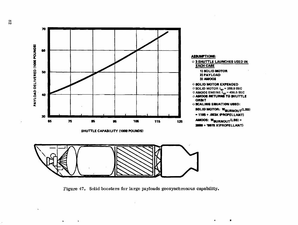
00 ~
iii a z :::> 2 I ::: a IU a: IU >:::; IU' a ~, 0 -' > ~
ML a
.. 50
40
30 1.65 75 IS 15 115 125
SHUTTLE CAPABILITY (1000 POUND$'
ASSUMPnOf!lS:
o 3 SHUTTLE LAUNCHES USED IN EACH CASE
,. SOLID MOTO" 2"AYLOAD 3,AMOOS
o IOLiD MOTOII EXPENDED o SOLID MOTOR Isp = 288.9 SEC o AMOOS ENG INE Isp =456.5 SEC o AMOOI RETU.... TO afUTTLE
ORBIT o .:ALINe EeuATIGN USEO:
_LID MOTOR: W...,"NOUT(LBS'
• 1115 + .0I3K fPfIOPELLANT'
MIOOS: W.,"NOUT(LBS'...+ _71 X(PROPELLANT)
Figure 47. Solid boosters for large payloads geosynchronous capability.
It
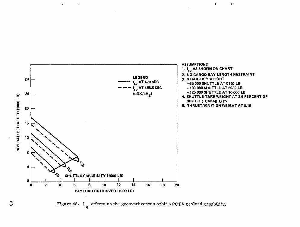
00 c,.)
m -J
8 0.0 w a:: w 2: -J w 0 0
~ -J
> ~
28
24
20
16
12
8
4
0 0 2 4
~ -aZ)
LEGEND - lap AT 470 SEC
- -- Isp AT 456.5 SEC
(LOX/LH2)
SHUTTLE CAPABILITY (1000 LB)
6 8 10 12 14 16 18
PAYLOAD RETRIEVED (1000 LB)
20
ASSUMPTIONS 1. Isp AS SHOWN ON CHART
2. NO CARGO BAY LENGTH RESTRAINT 3. STAGE·DRY WEIGHT
-65000 SHUTTLE AT 5150 LB -100 000 SHUTTLE AT 8030 LB -125000 SHUTTLE AT 10000 LB
4. SHUTTLE TARE WEIGHT AT 2.9 PERCENT OF SHUTTLE CAPABILITY
5. THRUST/IGNITION WEIGHT AT 0.15
Figure 48. I effects on the geosynchronous orbit APOTV payload capability.sp

co ....
a:I ...I
8 0 :: 0 w a: w >::::; w 0 0
~ ...I >« a..
32r.--------------------------------------------------------~ ASSUMPTIONS:
28
24
20
16
12
8
4
0 0
~ <" ......................65n..._
"V(J l.8 S,.,1Jt'r1.
£ C4P4811.rr}l'
2 4 6 8 10
LEGEND I sp AT 470 SEC
-- IspAT456.5SEC
(LOX/LH2 '
12 14 16 18
PAYLOAD RETRIEVED (1000 LB,
20
1. Isp AS SHOWN ON CHART.
2. NO CARGO BAY LENGTH RESTRAINT 3. STAGE DRY WEIGHT
-65000 SHUTTLE AT 6700 LB -100 000 SHUTTLE AT 8900 LB -125000 SHUTTLE AT 10 800 LB
4. NO HEAT SHIELD PROVIDED FOR RETURN PAYLOAD APPROXIMATE WEIGHT OF SHIELD WOULD BE 80 LB PER 1000 LB PAYLOAD RETURNED
5. SHUTTLE TARE WEIGHT AT 2.9 PERCENT OF SHUTTLE CAPABILITY
6. THRUST/IGNITION WEIGHT AT 0.15.
Figure 49. I effects on the geosynchronous orbit AMOOS payload capability.sp
"

00 CJ1
§ §...-... :c C)
W ~ o
9 > ~
~ ~ a:
~ 8 UI C)
APOTV AMOOS
16·~1----------------------~~--------------------~ DELIVERY n ONlYPAYlOAD~
14 , ROUNDTRIP PAYLOAD o
12
10
8
6
4
2
-10%
NOMINAL
-10%
+10%
NOMINAL
+10%
o ' y < I r < d I < <'1 ( ,. D I r , I I' L.
STAGE BURNOUT WEIGHT (POUNDS)
t; \"" an
o
~ ~ i l!3 ;!
:8... co
NOTES 1 HYDROGEN/OXYGEN
PROPELLANTS @ 456.5 SEC Isp
2 NO REDUCTION IN AMOOS ROUND TRIP CAPABILITY FOR PAYLOAD HEAT SHIELD. APPROX. VALUE IS8%OF ROUND TRIP PAYLOAD
3 NO REDUCTIONS OR INCREASES IN PROPELLANT DUE TO CHANGE IN STAGE CUT·OFF WEIGHT
4 SHUTTLE TARE WEIGHT o 2.9% OF SHUTTLE CAPABILITY
Figure 50. OTV payload capability sensitivity to burnout weight (65 000 lb Shuttle).
TABLE 28. GEOSYNCHRONOUS PA YLOAD PARTIAL SENSITIVITY
Partial
a (Pa;yload) a
a (Shuttle Capability)
a {Pa;yload} a (Burnout Weight)
a (Pa;yload) a (lsp)
Partial
a (Pa;yload} a
a (Shuttle Capability)
a (Pa;yload) a (Isp)
Payload Delivery
lb/lb
lb/lb
lb/sec 65 K Shuttle 125 K Shuttle
Payload Round Trip
Ib/lb
lb/sec 65 K Shuttle 125 K Shuttle
APOTV
0.1283
-2.6187
83 160
APOTV
0.0501
39 74
AMOOS
0.2496
-1.6016
61 118
AMOOS
0.1550
47 90
•
•
a. Includes the associated change in stage weight.
G. Oxidizer - Fuel Mixture Ratio Considerations for ON When used for delivery only missions, the OTV requires several thousand
pounds less propellant than when used for round trip missions. This is true for APOTV and AMOOS concepts. It should be advantageous if only one size tankage could satisfy both cases with a minimum effect on payload.
Figure 51 shows an example, using the AMOOS concept, where the nominal stage would be designed for full tankage for the round trip mission and to use a 7: 1 lox/hydrogen mixture ratio. The delivery mission would then be operated at a 6: 1 mixture ratio with the oxidizer tank slightly offloaded.
86

00 -::J
MIXTURE RATIO IO:FI 6,1 7,1
TANKAGE ROUNDTRIP DELIVERY ONLY ROUNDTRIP DELIVERY ONLY
... HYDROGEN 8800 6200
~ OXYGEN 41600 37000
- -TOTAL 48500 43200
Ii... ~ 0 « 0... >« AU>
5 !a::z: ~ >! III
"
*NOMINAL STAGE DESIGN FOR BOTH DELIVERY AND ROUND TRIP MISSIONS. SHUTTLE CARGO BAY EFFECTS AND STAGE WEIGHT EFFECTS MUST BE INCLUDED.
DELIVERY ONLY 16
14
13
12
11 40 42
HYDROGEN STORED II 500 LB/FT • STAGE LENGTH OXYGEN STORED II 7900 LBIFT . STAGE LENGTH
10 ROUNDTRIP
Ii... § !: I 0 I« 0... ~ AU> a :;) 0 z 0 a::z: ~ 7
8 III
" I 44 46 48 40 4Z
IENGINE. 7,1 MIXTUItE RATIO
44 48
5500
31500
-44000
STAGE PROPELLANT LOADING 11000 LBI STAGE PROPELLANT LOADING 11000 LB)
48
-
Figure 51. Oxidizer fuel mixture ratio considerations for OTV AMOOS with lox/hydrogen - 65 000 lb Shuttle capability.

Figure 51 also shows the corresponding effects on vehicle performance for this case. Operating the engine at the varying mixture ratios is an issue which should be resolved in OTV engine development.
A similar arrangement can be developed for the APOTV if desirable. The resulting capability effects would be similar.
IX. SHUTTLE CARGO BAY'LENGTH CONSIDERATIONS
A major problem associated with the OTV is the available length of the cargo bay. For the single Shuttle launch cases, the OTV and the payload must be carried in the same cargo bay. For the dual Shuttle launch case, it has been assumed that one-half of the payload weight would be carried in each of the cargo bays. This section deals primarily with the single launch case with lox/hydrogen propellants.
The length of the OTV plus payload is a function of the Shuttle payload capability minus the Shuttle tare weight, the OTV payload capability, and the OTV weight and propellant loading. As shown in the configuration, weight, and performance capability sections, these values are significantly different for the various OTV concepts. Payload weight and length characteristics may be found in the requirements section.
Shuttle improvement studies have indicated a need to maintain the 15 by 60 ft dimension of the current Shuttle. Early in the OTV study activity, it was determined that this could present some problems over the Shuttle capability range from 65 000 to 125 000 lb, particularly for the AMOOS. The same is true for APOTV at different capabilities within the range.
A. Single Shuttle Launch OTV - Lox/Hydrogen Propellants The payloads carried by the OTV may be represented by density to obtain
a volume needed by the payload. Figure 52 shows the AMOOS and APOTV cargo bay length requirements versus the geosynchronous payload capability. As shown for the delivery mode, the two concepts display essentially the same length requirement for equal payloads. The APOTV requires significantly more length than the AMOOS for the round trip payloads. It can also be noted that the APOTV requires much larger Shuttle capability than AMOOS.
88

00 <:.0
32 1 PAYLOAD VS LENGTH
AMOOS --APQTV ~
Ai 28 /' .... 65K SHUTTLE b. /'§ 100K SHUTTLE 0 ./
", .:: 24
125 K SHUTTLE 0 I!r:t"0a «0 .¥.:/.... > 20 « Q.,
DELIVERY ONLY /... zii A~ I ./' iii 2100cc 180 .... tl M .."!l ,cf' 8:E6
12 j~ROUNOTRIPONLV ClI
~ !:ii aa:
a: «0 x OCil (,)
8 ~ .... :l
Z I- 0 75> Zz M «00 .... a:Ilol ~ r----CURRENTCARGOBAY
.... xc:t Il0l(,)IL Z'4 t:.;, LENGTH AVAILABLE 0>a:CIlILo il0lil0l
O~ I I I I I I r; c:t 50 40, 45 50 55 60. 65 70 75 80 85 «a:CIlO
CARGO BAY LENGTH REQUIRED (FEET) :lu..
NOTES
G) MIXTURE RATIO 0 6:1
® PAYLOAD DIAMETER 0 14 FT
® PAYLOAD DENSITY
-DELIVERY ONLY 06 LB/Fr3
@ CONVENTIONAL DESIGN
APOTV
~TI AMOas
~=='I(==-'J"I, II
-ROUND TRIP 0 4 LB/FT3 @ VEHICLES SIZED FOR
MISSION (DELIVERY ONLY OR ROUND TRIP ONL YI
... -=-= -=-=":. ....I
PROPELLANT LOADING
SHUTTLE CAPABILITY (1000 POUNDS)
65 100
DELIVERY 0 PAYLOAD
ROUND ~ TRIP PAYLOADS
~ o ~
~ ~ «
125
~ ~
Figure 52. APOTV-AMOOS cargo bay requirements comparison (lox/hydrogen at 470 sec I ). sp
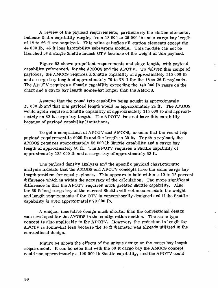
A review of the payload requirements, particularly the station elements, indicate that a capability ranging from 18 000 to 25 000 lb and a cargo bay length of 18 to 26 ft are required. This value satisfies all station elements except the 44 000 lb, 46 ft long habitability SUbsystem module. This module can not be launched by a single Shuttle launch OTV because of the weight of this payload.
Figure 53 shows propellant requirements and stage length, with payload capability referenced, for the AMOOS and the APOTV. To deliver this range of payloads, the AMOOS requires a Shuttle capability of approximately 115 000 lb and a cargo bay length of approximately 70 to 78 ft for the 18 to 26 ft payloads. The APOTV requires a Shuttle capability exceeding the 140000 lb range on the chart and a cargo bay length somewhat longer than the AMOOS.
Assume that the round trip capability being sought is approximately 13 000 lb and that this payload length would be approximately 24 ft. The AMOOS would again require a Shuttle capability of approximately 115 000 lb and approximatelyan 82 ft cargo bay length. The APOTV does not have this capability because of payload capability limitations.
To get a comparison of APOTV and AMOOS, assume that th~ round trip payload requirement is 6000 lb and the length is 20 ft. For this payload, the AMOOS requires approximately 55 000 lb Shuttle capability and a cargo bay length of approximately 50 ft. The APOTV requires a Shuttle capability of approximately 125 000 lb and a cargo bay of approximately 63 ft.
The payload density analysis and the specific payload characteristic analysis indicate that the AMOOS and APOTV concepts have the same cargo bay length problem for equal payloads. This appears to hold within a 10 to 15 percent difference which is within the accuracy of the calculation. The more significant difference is that the APOTV requires much greater Shuttle capability. Also the 60 ft long cargo bay of the current Shuttle will not accommodate the weight and length requirements if the OTV is conventionally designed and if the Shuttle capability is over approximately 70 000 lb.
A unique, innovative design much shorter than the conventional design was developed for the AMOOS in the configuration section. The same type concept is also applicable to the APOTV. However, the reduction in length for APOTV is somewhat less because the 14 ft diameter was already utilized in the conventional design.
Figure 54 shows the effects of the unique design on the cargo bay length requirement. It can be seen that with the 60 ft cargo bay the AMOOS concept could use approximately a 100 000 lb Shuttle capability, and the APOTV could
90
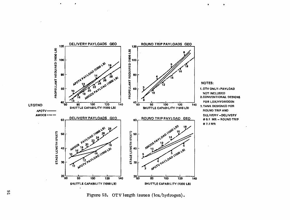
120 iii -' 8 0 ::100 Q w a: 5 c w 80a: I-z <t -' -' w 60 Q. Qa: Q.
4060 80 100 120
SHUTTLE CAPABILITY 11000 LBI APOTV-
LEGEND
AMOOS~--DELIVERY PAYLOADS GEO
601
j:: w 50 w ~ ::J: I
~ 40 w -' w CI <t I 30CIiI
20
DELIVERY PAYLOADS GEO ROUND TRIP PAYLOADS GEO 120
iii -'
~100 Q,,~ 16 w a:\'~ 5,..0 ,/ g 80~"O 14 /1.
:(4f\l" "" ,,'9' a: 28
.,sO 12 ~/24 \'~ ':< 22 0,..0 20 ..(-..:
V'"18 o0t; 16 ~
,,'9' 2:'--/\'\~ 28/
0,..0 24/ V,..-t\.i 22.)"
ot; 20 /" 16 r?0 .18 .Y ~,
16 ~-..: 14 \'" ,..0
12 V,..-t"O .,so~
60 80 100 120
SHUTTLE CAPABILITY (1000 LB)
to
NOTES:
1.0TV ONLY-PAYLOAD
NOT INCLUDED 2.CONVENTIONAL DESIGNSi:'t1%
I FOR LOX/HYDROGEN140 060 80 100 120 140 3.TANK DESIGNED FOR
SHUTTLE CAPABILITY 11000 LBI ROUND TRIP AND
DELIVERY -DELIVERY ROUND TRIP PAYLOAD GEO @ 6:1 MR - ROUND TRIP
@7:1MR 60
1
~50 w ~ ::J: I
~ 40 w -' w CI <ttii30
140 20
60 80 100 120 140
SHUTTLE CAPABILITY (1000 LB)
I-' Figure 53. OTV length issues (lox/hydrogen).

______
tl:) l'.:>
60 I
50
t= w w !:. % l-e" z 40 W ...J
W
:! e"
en
30
20
STAGE LENGTHS VS SHUTTLE CAPABILITY LOX/HYDROGEN - MR 07:1 (ROUND TRIP pL)
AMOOS / APOTV /
/ /'
/' /
/'
/' /" ~7UNIQUE
/- DESIGN
60 80 100 120 SHUTTLE CAPABILITY (1000 LB)
CONVENTIONAL DESIGN
AMOOS
~-::=-\ ;--:'::-~1
" ....' __J II'- __../-1\II
APO.,;...;--TV----.
c0D\· Figure 54.
UNIQUE DESIGN
AMOOS
~::='~=~:-~l ''::::-=-~--:..:-.:=~J
APOTV
r{)) )\
WEIGHT AND LENGTH LIMITS FOR 60 FOOT CARGO BAY LENGTH ACCOMMODATION
AMOOS:
SHUTTLE CAPABILITY AMaas LENGTH PAYLOAD LENGTH LENGTH TOLERANCE DELIVERY ONLY PAYLOAD ROUND TRIP PAYLOAD
AI'OTV:
SHUTTlE CAPABILITY MOTVLENGTH PAYLOAD LENGTH LENGTH TOLERANCE DELIVERY ONLY PAYLOAD ROUND TRIP PAYLOAD
100000 LB 34FT :M FT 2FT 21 000-22 000 LB 12500-13000 LB
12500 LB 34 FT 24FT 2FT 15500-16000 LB 55OO-MOO LB
OTHER POSSIBILITIES TO REDUCE LENGTH
• REDUCE ULLAGE FROM 6 % TO 4% iI '::::: OA FT
• USE 8:1 MIXTURE RATIO @ '::::: 1.5 FT
• USE 9:1 MIXTURE RATlOil~2.7 FT
• USE SLUSH HYDROGEN @ ~ ??
• RESHAPE EXTERIOR CONFIGURATION @ ??
Unique design to meet cargo bay length restraint.
~

use up to approximately 125 000 lb of Shuttle capability. Figure 54 also shows similar data for the conventionally designed OTV. The analysis indicates that these values are the approximate upper limits. Longer (lower density) payloads, heavier payloads, or more conventional OTV design is probably not a practical possibility and would require a longer cargo bay.
Limits on payload weights and lengths can now be established. These must be accompanied by specific lengths for the OTV (Fig. 54). Redesign of payloads may change the limits slightly; however, major changes are not expected.
Figure 55 depicts the conventionally designed OTV in a 60 ft cargo bay. This design would yield payload capabilities approximately the same as those given in Figure 54.
It is emphasized that while additional cargo bay length is very desirable, the redesign of the Orbiter would be quite expensive and weighty. Johnson Space Center (JSC) estimates that the Orbiter weight would increase by 685 lb/ft of length added to the cargo bay. The additional Orbiter weight would make Shuttle payload capability improvement Significantly more difficult.
x. CHEMI CAL ENG INE SYSTEMS FOR OTS
Consideration of potential engine systems suitable for OTV's in the 65 000 to 125 000 lb gross weight class has been restricted to chemical systems, which include cryogenic and storable liquid propellants and solid propellants. Electric (ion/plasma) and nuclear (solid/gas core) engine systems, which may be appropriate for post-1990 vehicles, have been excluded from this discussion.
Additional technical descriptions and parametric,data .can be found in Appendices A and B.
A. Cryogenic Propellant Systems As a point of departure, the lox/hydrogen RL10 Category liB engine
system was selected to characterize the 65 000 to 125000 lb class OTV. This engine has reasonably good performance and was the one selected for the MSFC Baseline Space Tug (1974). This engine can be made available with a moderate technological development, and a good data base and extensive parametric data
93
C.D ~
1-16 FT-I .. 43 FT ... [ - ---V -, >~ •
, \ "!':'. ~- ./ ...... -~ ......
100000 LB PAYLOAD CAPABILITY
1 FT
__r'7FT~I~___ :::,T rc -I I \ I
\ \ ,-- -..-.-
. \ I II, \
-_/ "
125000 LB PAYLOAD CAPABILITY
Figure 55. OTV with improved Shuttle (60 ft cargo bay).

exist. Nominal engine performance is based on a retracted nozzle engine length of 55 in. with an expansion ratio of 205: 1 (with nozzle extended) and a corresponding I of 456. 5 sec. Performance, as measured by I ,may be improved
~ ~ by increasing the nozzle expansion ratio. This expander cycle engine operates at a propellant mixture ratio of 6: 1 and a nominal thrust of 15 000 lbf.
The Advanced Space Engine (ASE) was selected to determine the advantages to the OTV of using a higher performing engine system. .The ASE has been used for some of the previous in-house MSFC Space Tug studies. A reasonable data base exists, and extensive parametric data are available. Nominal engine I is 470 sec at a nozzle expansion ratio of 400: 1 and a chamber pressure of sp
1600 psia. Thrust may be varied as desired over a range of approximately 8000 to 25 000 lbf to maintain whatever gross stage weight to engine thrust ratio is desired. The engine may be equipped with an extendable/retractable nozzle and operates at a nominal propellant mixture ratio of 6: 1, although this may be increased somewhat with a corresponding decrease in specific impulse. Propellants are lox/hydrogen, and the engine operates in a staged-combustion power cycle~
Consideration of projected lox/hydrogen propulsion systems has shown two other options which are performance competitive with the ASE. The first of these is the RLI0 Category IV, which represents the most efficient expander cycle engine. At an expansion ratio of 400:1 and chamber pressure of approximately 1000 psia, this engine produces an I of 470 sec. Nominal thrust is
sp 15 000 lbf, and the engine operates at a propellant mixture ratio of 6: 1. An extendable/retractable nozzle is optional.
The second high performance alternative to the ASE is the plug cluster concept, which is a grouping of multiple small engines around an aerodynamically designed central nozzle cone. For OTV application, a lox/hydrogen engine of 1500 lbf with an individual nozzle expansion ratio of 40: 1 has been selected. However, when appropriately arranged in the circular plug cluster geometry, the collective expansion ratio is 400: 1, resulting in an effective I of 466 sec.
sp The number of individual engine modules may be varied to adjust the total thrust as desired. The nominal propellant mixture ratio is 6: 1. The plug cluster design is presently undergoing conceptual evaluation and, therefore, must be considered only as theoretically attractive at this time, pending feasibility analysis and the usual demonstration testing.
In previous studies, certain versions of the lox/hydrogen aerospike engine have been considered for upper stage application. This engine, operating
95

in an expander cycle mode at a chamber pressure of 1000 psia, has been projected to produce an I of 470 sec at an effective expansion ratio of 200:1.
sp Although theoretically competitive with bell nozzle engines from weight considerations and having certain advantages because of its short length, severe difficulties in demonstration hot firings of prototype aerospike hardware led to cancellation of Air Force Rocket Propulsion Laboratory (AFRPL) and NASA test programs. Development of an aerospike engine is presently considered to be a high risk, high cost program and, therefore, is not included among the principal candidate engine systems for the OTV. Figure 56 gives engine configuration data on the systems discussed here.
B. Storable Propellant System s Although lower performing than cryogenic systems, as measured by
delivered I ,storable propellant engine systems may find a role in the OTS if sp
extended orbital stay time is a requirement. In this event, several types of storable propellant systems may be considered. The first of these is an N20 4/
MMH engine derived from the Shuttle Orbiter 6000 lbf Orbit Maneuvering Engine (OME) (I = 313). Significant modifications would be required for OTV applica
sp tion; however, these would not represent advances in the state-of-the-art. Changes would be required for operation in a pump-fed mode instead of the present pressure-fed mode, and increases in engine thrust to higher levels for OTV application would be necessary. Increasing the propellant mixture ratio from 1.65: 1 to 2: 1 would increase engine performance as would increasing the nozzle expansion ratio. I would typically range from 325 to 330 sec.
sp
Improved performance for storable propellant engines may be achieved by increasing the chamber pressure to a practical maximum of approximately 1000 to 1500 psia. The gas-generator and staged-combustion cycle engines have been investigated (e. g. , Aerojet contract NAS 8-29806), with all engines using N20 4 and MMH as propellants, and are fuel cooled. These engines produce I
. sp ranging from 335 to 349 sec, depending upon engine thrust, nozzle expansion ratio, chamber pressure, percent fuel used for film cooling (i. e., allowable chamber wall temperature), and overall engine propellant mixture ratio.
A third type of system may be included in this category if liquid oxygen is considered to be a space storable propellant. These systems would use the lox as oxidizer and hydrocarbon or amine fuels. Engine systems of this design would produce I ranging from 380 to 388 sec at an expansion ratio of 400: 1,
sp with MMH having the higher performance (and cost). Engine design data base is poor, with the result that these engines are not well characterized at this time.
96

(Q -:]
I • ~. I
ttT
RL 10 CAT II B
!' i· !
iIi,... , CIA
i;'ilIii I': :!I IIi !~ If·_
I. 114.00 ------~ I
ENGINE REFERENCE PLANE
DIA
';L~
'-i"~f~---- '". 125~7.80 -"-'::t:::::+:-~32.a74 '. __..
57.00
... RL10CATIV
"
)1,: IjI,Ii,III, ,6S.2O
ill I
1:·401
I • ENGINE LENGTH .....0 INCHES -I EXTENDED .
~~{\~l:!e!l!!I-1-=,.J
ASE
PLUG CLUSTER
Figure 56. Engine configurations.
C. Solid Rocket Motors Solid propellant rocket motors offer an alternative to storable propellant
engine systems for extended orbit stay time and may be preferable for some applications. An OTV using solids for main propulsion would draw heavily on the technology established for the IUS being developed by the Air Force for Shuttle upper stage application. These vehicles would utilize Class 2 propellants producing I ranging from 290 to 300 sec, depending upon nozzle expansion ratio
sp and propellant composition. Solid propellants offer the advantages of high bulk density and reliability and may, over limited ranges, have variable propellant loadings to accommodate different mission impulse requirements. More detailed engine data and development status may be found in Appendix A.
D. Summary To date, OTV studies have shown the lox/hydrogen engines to be the most
desirable systems for the 1985-1990 time frame. Maximum practical engine performance (I ) is needed. An additional requirement, which evolved in this
sp study, is for the engines to use higher and varying oxidizer-to-fuel mixture ratios. This is an issue which should be addressed in near future technology efforts.
XI. MI SSION MODEL CAPTURE FOR 65 000 AND 100000 Ib SHUTTLE CAPABILITIES
Comparisons of the AMOOS and APOTV using lox/hydrogen propellants for the 65 000 and 100 000 lb Shuttle capabilities are given in this section. The capture shown here is consistent with the candidate missions shown in the Requi rements section.
For this analysis it has been assumed that the heavier payloads would be designed to fit within the capabilities which would result for each Shuttle capability. Whether single or dual launches were assumed is indicated.
Data are presented for the nominal and low program options defined in the Requirements section. For the Nominal Program Option, an HLL V has been assumed in 1991, and at that time unmanned payload hardwares would be transferred to the HLL V • For the Low Program Option, no HLL V is assumed. Also for the Nominal Program Option, a four-man crew transfer capability is assumed prior to 1991, and a 12-man transfer capability is assumed thereafter. Only a four-man capability is asslUned in the Low Progrnm Option.
98

The capture shown here does not consider cargo bay length restraints. However, the analysis in the section on Shuttle cargo bay length issues indicates that the 60 ft cargo bay will accommodate the capture if the OTV length is limited to approximately 34 ft, which requires unique/innovative OTV structural design. For the 65 000 lb Shuttle capability case, there would be no problem with the conventionally designed OTV for either case, and the qualification here is only for the 100 000 lb Shuttle capability case.
A. 65 000 Ib Shuttle Capability Compari son A tabulated summary of the Shuttle launches by the APOTV with a 65 000 lb
Shuttle capability for the Nominal Program Option is shown in Table 29. The majority of the missions require dual Shuttle launches with two-stage OTV's. The capability for a 30 day sortie mission is not possible and would probably require some type of orbital assembly. Al so the 12-man crew transfer capability is marginal.
A tabulated summary of the Shuttle launches by the AMOOS with a 65 000 lb Shuttle capability for the nominal program option is shown in Table 30. Approximately 25 to 35 percent of the missions require dual Shuttles with two-stage OTVts. This value may be higher depending on the nature of Satellite Power System (SPS) and Public Service Platform (PSP) payloads. The sortie mission requires dual launches. The 12-man crew transfer would be possible but was not used here.
The nominal program from 1986-1995 will require approximately 643 Shuttle launches if APOTV is selected and approximately 380 Shuttle launches if AMOOS is assumed.
Similar launch requirements for the Low Program Option for APOTV and AMOOS are shown in Tables 31 and 320 The findings are similar with reduced launch rates. The APOTV requires approximately 317 Shuttle launches, and the AMOOS requires approximately 198 Shuttle launcheso
B. 100000 Ib Shuttle Capability Comparison Tabulated values for the Nominal and Low Program Options, with a
100 000 lb Shuttle capability for the APOTV and AMOOS, are shown in Tables 33 through 36.
99

I-' o o
TABLE 29. NOMINAL PROGRAM OPTION, 65 000 lb SHUTTLE/APOTV
470 I - Lox/Hydrogen sp
Single and Dual Launches
Units Program 86 87 88
Calendar Year
89 90 91 92 93 94 95 Remarks
Shuttle Launches (Mission Weight)
Station Elements
Station Cargo
SPS - Test/Development Hardware
Space Construction Base Miscellaneous
PSP
Solar Terrestrial Observatory (STO)
PSP and STO Miscellaneous
Automated or Cluster Payload
5
4
5
2
8
4
10
1
3
5
4
8
10
3
5
8
11
8
5
2
5
8
18
5
6
5
8
15
4
2
2
5
4
17
4
7
3
5
4
2
4
5
4
11
6
7
3
2
4
5
Dual Launch
Subtotal 16 26 35 39 42 36 32 23 28 14
Shuttle Launches
(Mission Flights)
4-Man Crew Transfer
Station Supplies
12-Man Crew Transfer
4-Man Sortie
Planetary
Lunar
High Altitude and Heliocentric
6
2
1
8
.4
6
1
1
8
4
3
2
1
12
6
6
0
1
1
16
8
3
2
2
24
12
6
1
2
24
3
2
1
1
32
6
2
1
36
18
2
1
52
18
2
1
1
Dual Launch
Marginal
Repair Orbital Assembly
Subtotal 9 20 18 26 31 45 31 41 57 74
Program Total 25 46 53 65 73 81 63 64 85 88
I
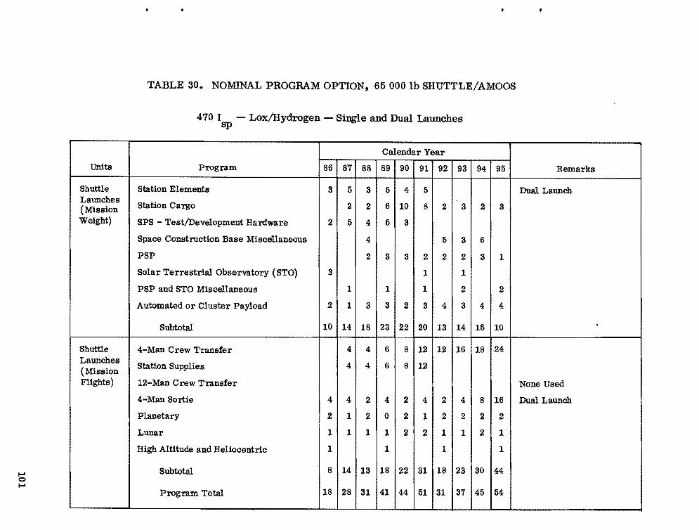
1-' o I-'
Units
Shuttle Launches (Mission Weight)
Shuttle Launches (Mission Flights)
TABLE 30. NOMINAL PROGRAM OPTION, 65 000 lb SHUTTLE!AMOOS
470 I - Lox/Hydrogen - Single and Dual Launches sp
Program
Station Elements
Station Cargo
SPS - Test/Development Hardware
Space Construction Base Miscellaneous
PSP
Solar Terrestrial Observatory (STO)
PSP and STO Miscellaneous
Automated or Cluster Payload
Subtotal
4-Man Crew Transfer
Station Supplies
12-Man Crew Transfer
4-Man Sortie
Planetary
Lunar
High Altitude and Heliocentric
Subtotal
Program Total
86 87 89
3
88
5 3 5
2 62
2 5 4 5
4
2 3
3
1 1
2 3
10
1 3
14 23
4
18
4 6
4 4 6
4 4 42
2 1 02
1 1 1 1
1 1
8 14 18
18
13
28 4131
Calendar Year
90
4
10
3
3
2
22
8
8
2
2
2
22
44
91
5
8
2
1
1
3
20
12
12
4
1
2
31
51
-
92
2
5
2
4
13
12
2
2
1
1
18
31
93
3
3
2
1
2
3
14
16
4
2
1
23
37
94
2
6
3
4
15
18
8
2
2
30
45
95
3
1
2
4
10
24
16
2
1
1
44
54
Remarks
Dual Launch
.
None Used
Dual Launch
I

~ TABLE 31. LOW PROGRAM OPTION, 65000 lb SHUTTLE/APOTV I),j
470 I - Lox/Hydrogen - Single and Dual Launches sp
Units Program 86 87 88
Calendar Year
89 90 91 92 93 94 95 Remarks
Shuttle Launches (Mission Weight)
Station Elements
Station Cargo
SPS - Test/Development Hardware
Space Construction Base Miscellaneous
PSP
Solar Terrestrial Observatory (STO)
PSP and STO Miscellaneous
Automated or Cluster Payload
4
2
3
3
2
2
2
5
4
2
5
7
2
5
5
5
4
5
5
2
5
5
4
2
7
5
2
2
4
5
5
7
5
7
5
5
7
2
7
Dual Launch
Subtotal 9 9 16 14 19 12 18 18 24 26
Shuttle Launches (Mission Flights)
4-Man Crew Transfer
Station Supplies
12-Man Crew Transfer
4-Man Sortie
Planetary
Lunar
High Altitude and Heliocentric
6 6
2
6
3
6
8
4
3
2
12
6
6
8
4
3
2
12
6
6
8
4
3
2
12
6
6
Dual Launch
.
Marginal
Repair Orbital Assembly
Subtotal 6 8 15 17 24 17 24 17 24
Program Total 9 15 24 29 36 36 35 42 41 50
..

Units Program
Calendar Year
Remarks86 87 88 89 90 91 92 93 94 95
Shuttle Station Elements 3 4 3 3 3 Dual Launch Launches. (Mission
Station Cargo 3 3 3 3 4 3
Weight) SPS - Test/Development Hardware 2 2 3 4
Space Construction Base Miscellaneous 2 2
PSP 1 1 1 1 1 1
Solar Terrestrial Observatory (STO) 1 2 1
PSP and STO Miscellaneous 1 1 2
Automated or Cluster Payload 2 1 3 3 3 3 4 3 4 4
Subtotal 5 5 9 8 11 7 10 10 14 15
Shuttle 4-Man Crew Transfer 3 4 6 4 6 4 6 Launches (Mission
Station Supplies 3 4 6 4 6 4 6
Flights) 12-Man Crew Transfer None Assumed
4-Man Sortie 4 4 4 2 4 2 4 2 4 Dual Launches
Planetary
Lunar
High Altitude and Heliocentric
2 2 2 2
Subtotal 4 6 10 12 16 12 16 12 16
Program Total 5 9 15 18 23 23 22 26 26 31
TABLE 32. LOW PROGRAM OPTION, 65000 lb SHUTTLE/AMOOS
470 I - Lox/Hydrogen - Single and Dual Launches sp
~ (0
I
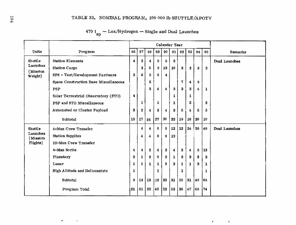
...... o
'*"' TABLE 33. NOMINAL PROGRAM, 100000 lb SHUTTLE/APOTV
470 I - Lox/Hydrogen sp
Single and Dual Launches
Units Program
Calendar Year
Remarks86 87 88 89 90 91 92 93 94 95
Shuttle Station Elements 4 5 4 5 5 5 Dual Launches Launches
Station Cargo 3 5 8 13 10 3 2 3 2 (Mission Weight) SPS - Test/Development Hardware 3 6 5 6 4
Space Construction Base Miscellaneous 5 7 4 8
PSP 3 4 4 2 3 2 4 1
Solar Terrestrial Observatory (STO) 4 1 1
PSP and STO Miscellaneous 1 1 1 3 2
Automated or Cluster Payload 2 2 4 3 4 3 5 4 5 5
Subtotal 13 17 26 27 30 22 18 16 20 10 •
Shuttle 4-Man Crew Transfer 4 4 6 8 12 12 24 36 48 Dual Launches Launches (Mission Flights)
Station Supplies
12-Man Crew Transfer
4 4 6 8 12
4-Man Sortie 4 4 2 4 2 4 2 4 8 12
Planetary 2 1 2 0 2 1 2 2 2 2
Lunar 1 1 1 1 2 2 1 1 2 1
High Altitude and Heliocentric 1 1 1 1
Subtotal 8 14 13 18 22 31 18 31 48 64
Program Total 21 31 35 45 52 53 36 47 68 74
-

TABLE 34. NOMINAL PROGRAM, 100 000 Ib SHUTTLE/AMOOS
470 I - Lox/Hydrogensp
Calendar Year
Units Program 86 87 88 89 90 9291 93 94 95
Shuttle Launches (Mission Weight)
Shuttle Launches (Mission Flights)
.... o
Station Elements
Station Cargo
SPS - Test/Development Hardware
Space Construction Base Miscellaneous
PSP
Solar Terrestrial Observatory (STO)
PSP and STO Miscellaneous
Automated or Cluster Payload
Subtotal
4-Man Crew Transfer
Station Supplies
12-Man Crew Transfer
4-Man Sortie
Planetary
Lunar
High Altitude and HeUocentr.l.c
Subtotal
Program Total
2
2
2
1
7
2
2
1
1
6
13
3 2 3 3 3
72 41 6 2 1
3 3 3 2
3 4 2
2 32 1 2 1
1 1
1 1 1 1
1 2 2 2 2 3 2
10 1513 17 14 11 8
4 4 6 8 12
4 8
2 21 1 2 1 2
01 2 2 2 21
1 1 1 2 2 1 1
1 1
8 8 10 13 17 9 13
18 3021 25 2031 21
•
Remarks
I
I
Carried on Crew Transfer Launch or after 1991 on HLLV
2
5
2
3
12
1
1
2
3
7
12
4
2
2
20
32
24
6
2
1
1
34
41 01

.... TABLE 35. LOW PROGRAM OPTION, 100000 lb SHUTTLE/APOTVo 0")
470 I - Lox/Hydrogen - Single and Dual Launches sp
Calendar Year
Units Program 86 87 9088 89 91 92 93 94 95 Remarks
Shuttle Station Elements 4 5 4 4 3 Dual Launches Launches 4 4 4 4 5 4Station Cargo(Mission Weight) SPS - Test/Development Hardware 2 4
Space Construction Base Miscellaneous 3 3
PSP 1 2 1 1 2 1
Solar Terrestrial Observatory (STO) 1 13 ,
PSP and STO Miscellaneous 1 3
Automated or Cluster Payload
2
32 2 4 4 5 4 5 53
5Subtotal 9 12 9 15 9 13 14 14 13
Shuttle 6 88 12 12 8 12 Dual Launches Launches
4-Man Crew Transfer
6 43 4 6 4 6Station Supplies (Mission Flights) 12-Man Crew Transfer
4-Man Sortie 4 4 Capability Marginal
Planetary
4 2 4 2 4 2 4
2 2 2 2
Lunar
High Altitude and Heliocentric
4 6 13 16 22 16 22 16 22Subtotal
5 13 18 22 31 31 29 36 30 35Program Total
~ ..

•
TABLE 36. LOW PROGRAM OPTION, 100000 Ib SHUTTLE/AMOOS
470 I - Lox/Hydrogensp
Units Program
Calendar Year
Remarks86 87 88 89 90 91 92 93 94 95
Shuttle Station Elements 2 3 2 2, 2 Launches (Mission Station Cargo 3 2 2 2 3 3
Weight) SPS - Test/Development Hardware 2 1 2 3
Space Construction Base Misbellaneous 2 1
PSP 1 1 1 1 1 1
Solar Terrestrial Observatory (STO) 1 1 1
PSP and STO Miscellaneous 1 1 1
Automated or Cluster Payload 1 1 2 2 2 2 3 2 3 3
Subtotal 4 4 7 6 8 5 7 7 10 12
Shuttle 4-Man Crew Transfer 3 4 6 4 6 4 6 Launches (Mission Station Supplies
Flights) 12-Man Crew Transfer 2 2 2 1 2 1 2 1 2
4-Man Sortie
Planetary
Lunar
High Altitude and Heliocentric
2 2 2 2
Subtotal 2 4 5 7 8 7 8 7 8 I
Program Total 4 6 11 11 15 13 14 15 17 20
f-' o ....:]
The APOTV findings are similar to the 65 000 lb case with dual launches being required. The 12-man crew transfer capability and a marginal 4-man 30 day sortie mission using dual Shuttle launches is possible.
The AMOOS findings are somewhat better with the possibility that dual Shuttle launches can be a voided.
The Nominal Program Option requires launching approximately 466 APOTV's or approximately 252 AMOOS's. The Low Program Option requires launching approximately 250 APOTV's or approximately 126 AMOOS's.
C. Annual Launch Rate Comparison Figure 57 shows graphical comparisons of the Shuttle launches required
by the APOTV and AMOOS for the 65 000 and 100 000 Ib Shuttle systems, respectively. As can be seen, the AMOOS requires approximately 60 percent as many Shuttle launches as APOTV for the 65 000 lb Shuttle capability. The AMOOS improves slightly for the 100 000 lb Shuttle case and only requires approximately 51 to 54 percent as many launches as APOTV.
Figure 57 also reflects the Shuttle launch rate comparisons for the APOTV and AMOOS and summarizes the same data for a 10 year rate. It can be seen that the AMOOS with the 65000 lb Shuttle is more attractive than the APOTV with a 100 000 lb Shuttle. Also, the AMOOS can perform the Nominal Program Option with only a few more flights than APOTV can perform the Low Program Option.
XII. PROGRAM SCHEDULES AND COSTS
The two prinCipal OTV concepts which have been investigated are the APOTV and the AMOOS. In this section AMOOS is sometimes referred to as • A MOTV. Program schedules and costs for those OTV's for the high performance lox/hydrogen systems are given in this sectiono Development, schedules, schedule differences, cost, and cost differences are shown for each stage concept. Finally the two concepts are compared.
The reader should note that the program schedules and cost information shown from pages 109 through page 120 is for analYSis and concept comparison purposes. Schedules and costs for planning usage are given in Section E beginning on page 121.
•
108

::; 1:.0
> ~
~ aiDz<C :;) ~ Ou " ... i~
3
> ~
~ Qj
a«z"
~~ §~g!;-3
13100 r
NOMINAL PROGRAM
~ 75\ 10""'-=) I ,r I / ..I ... i=! 50 I .£I F'w:1 ~ t , 7, I :;)
ili ;p5r,..c I T ;:) z HLlV IN 1991 ~ 0 1 I I 1
..I
~ z
86 B8 90 92 94 96
NOTES:
CALENDAR YEAR
AMOOS ('l)DUAL STAGES FOR HEAVY
ELEMENTS AND PAYLOADS
(%lDUAL STAGES FOR 4 MAN
SORTIE MISSIONS
NOMINAL PROGRAM
/7
.,.""1'='.1/1 j
~ OLI____~__~L___~____~--~ 86 B8 90 92 94 96
NOTES:
CALENDAR YEAR
AMOOS
\J)6TA. SUPPLIES CARRIED WITH
4 MAN CREW MODULE
1%;12 MAN CREW MODULE @ 1991
<3)CARGO BAY LENGTH PROBLEM
-REQUIRES UNIQUE DESIGN.
LOW PROGRAM OPTION
~ l00ri----.----y----,---~~---
%
~ ~ 1511---i----+---~--~l---~ ..I ... ..I ~ ~ ~
ili ..I
§ZZ «
B8 90 92 94
CALENDAR YEAR
APOTV
'l,DUAL STAGES fOR HEAVY ELEMENTS
HEAVY PAYLOADS AND CREW TRANSfER
(%lORB. ASSY. ANDIOR SPECIAL HARDWARE
REQUIRED FOR 4 MAN SORTIE MISSION
LOW PROGRAM oPTION
CII 100... %
~ ~ 75« ..J
5 )
...
..J ~ ~ ~ % CII
~ 25 :::>
~~ .-' iP'M~~ ,- INOHLLV'z z
« 0 ~ 86 B8 90 92 94
CALENDAR YEAR
APOTV
·l'DUAL LAUNCHES USED fOR HEAVY
elEMENTS, CREW TRANSfeR AND
96
4 MAN SORTIE (CAPABILITY TO PERFORM
THE 4 MAN SORTIE IS VERY OUESTIONABLE'
> ~ ... -
..I:
l: ~ ~"r« CIIU
r--." 0
02:5 ~ ",0""I>
g~0'521>
'-
,
TOTAL PROGRAM CAPTU RE/LAUNCHES
REQUIRED
TOTAL SHUTTLE LAUNCHES REO'D
APOTV AMOOS
NOMINAL LOW NOMINAL LOW PROGRAM PROGRAM PROGRAM PROGRAM
643 317 380 198
-------
466 250 252 126
-_.
Figure 57. Total program capture/launches required.

A. Schedules (For APONIAMOOS Comparison) Guidelines for the program schedules for the OTV concepts which follow
are for orbit flight tests in 1985 and initial operations capability (IOC) in 1986. Capture cost comparisons reflect OTV usage for the 10 year period from 1986 to 1995. A Phase C/D start in 1980 is assumed.
B. Engine Development The lox/hydrogen RL..,10 category JIB engine system, as proposed by
MSFC and defined by the Pratt and Whitney (P& W) Company, has been extensively used in previous OTV studies. This engine was selected for the MSFC baseline Space Tug in 1974. This engine development schedule as proposed by P& W is shown in Figure 58.
The schedule shows approximately 1 year of flexibility. It does not, however, allow for a new startup which will be required if the current RL-I0 A3-3 engine product line is shut down in 1978 as has been indicated by P& w.
The RL-I0-IIB engine technology is partially proven, and the engine performance at an expansion ratio of 205: 1 was demonstrated by hot firings at Amold Engineering Development Center (AEDC) in 1976. Only minimum supporting research and technology (SRT) efforts are required. An engine definition update would be required in FY-79.
The ASE being developed by Rocketdyne and NASA/Lewis Research Center (LeRC) was chosen to be representative of later propulsion system technology.. This engine system was extensively studied by MSFC in 1972. The development schedule for the ASE is also shown in Figure 58. Scheduling information developed by P& W for the RL-I0-IV was used as a basis for the ASE schedule which is shown.
The ASE requires considerable SRT and performance verification testing. A 15 month Phase B program is required in FY-78/79.
The development schedule for APOTV, in Figure 59, was based on schedules developed in the Phase B Space Tug studies by General Dynamics Corporation (GDC).
A 12 month Phase B activity is required in FY-78/79. Phase Cj.D begins in April 1980 for first vehicle delivery in October 1984. Vehicle production rate is two per year, and there are no apparent critical scheduling problems.
110
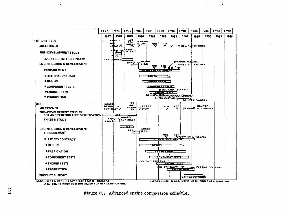
..
RL-10-11 B
MILESTONES
PRE-DEVELOPMENT STUDY
ENGINE DEFINITION UPDATE
ENGINE DESIGN & DEVELOPMENT
O. AHE D CID PDR CDR UP ATIEV ~ ~ V V '9---9 DEL. FLt. ENGINU A~RO t~~ AWAR I
PR ~e NTHAWARD J
P OC. l DE .... U ATEc:::::::l
R"'P AWA I) '0" WO. RE ASE ~ <P C POR COR / DEL. F.t. ENGINU
PROCUREMENT
PHASE CID CONTRACT
• DESIGN
e COMPONENT TESTS
eENGINE TESTS
e PRODUCTION
AWARe DEFINIIION
ASE MILESTONES CONTR CTV
PRE-DEVELOPMENT STUDIES SRT AND PERFORMANCE VERIFICATIONI 3RT
I QOIAN .lwlLoUJ V~L.D""""T
c...= DESIGN ..........
~~~~lr:AT1ON
I cbllPCINENT TEST£] ENG.
~ilm:m!ilfli~!tDE'L.-hT. ENGIIIIES
HQ'S
GO· I AW.,RDAH~D vrpC.f:I
poRi V I
CDR I 1_ V V---1""'"
DELivER FloT.lENGINE
. !
PHASE B STUDY - R"'P~ co TRACTATRD •
PROCc::::!
---1'lnJ""I
ENGINE DESIGN & DEVELOPMENT PROCUREMENT
PHASE CID CONTRACT
RF~"'WAlrtDc::::J rp C/P
PDR I C;ii'o% owe. RELE+E DI5I48 , O\vtLop~ T " I
eDESIGN
eFABRICATION
eCOMPONENT TESTS
e ENGINE TESTS
e PRQDUCTION
PRODUCT SUPPORT
I I .......bIC'4&
I L_ flAIRll:4TION
I I I ~OAPONENT tEsts
DEL. NO. TP ENG'iiI , ~IHi iESTS J
I EL. STV ENG ~ !--__ ;:y FLT liNG. DELlvERV i fI 61. 'M . .
"lfODufl'SU~T
I-' I-' I-'
NOTE: USEOP. ws RL-l0 CAT. II. ENGINE SCHI:DULE"'$ USED P.W·S RL-IO CAT. IV I:NGINE SCHEDULE AS A GUIDELINE A GUIDt;LINE WHICH DOES NOT ALLOW "'OR NEW START UP TIME.
-,
Figure 58. Advanced engine comparison scheduleo
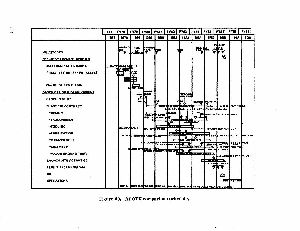
..... ..... N)
MILESTONES
PBIH21ili!IiL.OPMlliflllITUD'U
MATERIALS SRT STUDIES
PHASE B STUDIES (2 PARALLEL)
IN-HOUSE SYNTHESIS
APOn DElIGN a DEli!RQPMENT
PROCUREMENT
PHASE C/D CONTRACT
-DESIGN
-PROCUREMENT
-TOOLING
-FABRICATION
-SUB-ASSEMBLY
-ASSEMBLY
-MAJOR GROUND TESTS
LAUNCH SITE ACTIVITIES
FLIGHT TEST PROGRAM
IOC
OPERATIONS
.
I FY77 I FY18 I FY781 FY80 I FY81 I FY82 I FY83 I FY84 I FY85 I FY86 I FY87 I FY881
1977 1978 1919 1980 1981 ,1982 1983 1984 1985 1986 1987 1988
.,WARD HCI'S ~RD ;- C ~R ~.\ T ; ~T 9 . ~EA
jiH. V V' V IVV'
.0IOC
R r15 D
~ TA,.. t
5 ~t AWARD
R~ PH r F c~J --" ~........
(Sn FI.T.VE .1 R tc. STY I NG..- r-R C.IST F T.AST' ONICS
I=~: .'iiA'bj ... r R£C FLT.EN INES D' fI ...
T,K ~ eLY
)ELSTV ,ANK ~"'D'w' STAR ISTFL't VEH. , \'t
STYIA IiTRION. Isc.... .... V V
._T FI. .ASTRI NICS C( ~P\"ETE
s IYCOMP -"TYee -....EYE !IV \'t \'t ~I .'ith. ST FI.T VEH
.VEH.
• GIN DYI _te ..... .,... fZVEt< PER VA
~GINS RUCT. L9 .ll INSTA 1CTEST
........ H l$TF T.VEH.\'t
FUC!I:I TESTS ... 17 ...
.0fOC
NOTIl: _DQO 'SLOW II$KAI -- ..... ETUC SCHEDii LEASA W'DELI e
Figure 59. AParV comparison schedule.
,

A development schedule for the AMOOS, which is directly comparable with the APOTV schedule previously mentioned, is shown in Figure 60. Major differences in the AMOOS and APOTV schedules are the large vehicle SRT for development of the aeromaneuvering capability, with appropriate guidance and navigation and the ablative heat shield.
The AMOOS also needs a 12 month Phase A which is scheduled for FY-78. If the Phase C/D and OTV delivery dates are held at the same schedule as shown (and as shown for APOTV), the AMOOS schedule shows a critical problem in having adequate procurement time for both Phase A and Phase B studies. The AMOOS schedule shown in Figure 61 reflects a combination Phase AlB which eliminates one procurement cycle and tends to be less time critical.
C. Schedule Comparison The schedule analysis indicates that the RL-10 derivative engine and the
ASE can be developed to meet the assumed schedules. The ASE represents a newel' technology system, and more development is required. Future OTV study efforts should include further engine development schedule analysis to minimize schedule risk and to assure minimum developmental cost.
The schedule analysis indicates that the APOTV and AMOOS concepts can be developed to meet the assumed schedule. The AMOOS concept requires a tighter schedule to accomplish the design and development needs. To meet the development schedule, the AMOOS concept requires a combined Phase AlB effort. Future OTV study effort should include further schedule analysis to minimize schedule risk and to assure minimum developmental cost.
D. Program Costing (Comparison) Program costs have been determined for the lox/hydrogen propellant
APOTV and AMOOS. The cost values which are shown for the two concepts 'are .. directly comparable. No costs have been determined for the space storable or Earth storable type OTV systems shown in other sections of the report. The primary purpose of the costing analysis was to determine the cost differences associated with the development and operation of each OTV concept. The effects on the Shuttle, different launch facilities required for the Shuttle due to different launch rates for each concept, any cost on the payloads due to concept differences, etc., were not considered.
113

..... ..... ,;..
IFY77
MILESTONES
FRE-DEVELOPMENT STUDIES AMOTVSRT IHEAT SHIELD, AERO
MANEUVERING, G8.N, ETC.I
PHASE A STUDIES 12 PARALLE U
PHASE B STUDIES 12 PARALLELI
IN-HOUSE SYNTHESIS
AMOTV DESIGN 8. DEVELOPMENT PROCUREMENT
PHASE CIO CONTRACT
• DESIGN
• PROCUREMENT
• TOOLING
FABR ICA TION
• SU8-ASSEMBLY
• ASSEMBLY
• MAJOR GROUND TESTS
LAUNCH SITE ACTlVIT!:S
FLIGHT TEST PROGRAM
• DELIVERY FLIGHT ROUND TRIP W/SHUTTLE RECOVERY
DELIVERY FLT. WIGND RECOVERY
INITIAL OPERATING CONDITION
OPERATIONS
9/1 1918 l"J19 19110 ~981
AW_ AWARD
T-~r.V
RFP I ....""0 : ..
SVNTHE SVIWTHHtS I
POA
V
m¥T~~'~
19'17 I 1983 9O%-OWG
~ IR~EASE
9O'-DWG-'i' I~LEAS.
1984 198!) 1986
OEltVlR I reST fUGtf'f$
1ST '\7 Y" v-YV 0IOC
1987
OI.l I..... W:"o~ v·Z
(S nf f'U ViEM.)
="TTfW-'l" f====t======::m~mx:::::~
Ir rUTfLT_l
V i--TEST FLT *:2
NOTE: USED GDC'S LOW RISK ALL PROPULSIVE TUG SCHEDULE AS A GUIDELINE
• V-T£ST HT·3
.ce 0
19H8
Figure 60. AMOTV comparison scheduleo
.. •

--
•
!917 1978 1979 1980 1981 1982 1983 1984 1985 1986 I 1987 I 1988 _DWG DELIVERJ_
SntfLT.YE",1
OEL 2ND FLT VEH
l1"UHCH1STFLT
,.....T...TFLT .. '
t-TEST FLT,. 2
f"" TEST FLT .. 1
ICC o
TEST FLIGHTSMen ~J,RD 'OR '\tEAS£MILESTONES ~V V0 1STF~Tv-n·
PRE-DEVELOIPMENT STUDIES AMOTVSRT tHEAT SHIELD, AERO
MANEUVERING, G&N, ETC.)
DEFINITION STUDIES 12 PARALLEL)
OA
: I I
.Jv.:t.::...j..IN-HOUSE SYNTHESIS I
AMOTV DESIGN &: DEVELOPMENT .... ow.. ..n. lOll.irT~~R~PROCUREMENT WK.• 1 WM. #2~I~LE..S( a '0'
PHASE CIO CONTRACT
• DESIGN , . '.OO~.~!='"m"'._~ I R(C.RAW ....~ECSTV! 1V=..C~·CFLHNGI"E$
• PROCUREMENT i i·er: @ ?\ .. 1 EE
• TOOLING IitT 1ST FLT V(H
• FABRICATION ~=~=~Jdf::=~=F3.LT .JTRIONICS COMPLETE
~~~:::}I I• SUB-ASSEMBLY DEL 1ST FLT VEH
I t:==:Z:?::IIlI:i=~=~_1'2VEHPEA-YAI• ASSEMBLY BEGIN OVttAllt(: TEST I
.." .. A........... MAT. nm _BEG.N STRUCT TEST "VJLv:: 8EG'" STATIC TESTS
• MAJOR GROUND TESTS Y I ; ~bIESlS~ Ii'''ft" ILAUNCH SITE ACTIVITIES
IFLIGHT TEST PROGRAM
V• DELIVERY FLIGHT • ROUND TRIP W/SHUTTLE RECOVE RY
• DELIVERY FLT. W/GND RECOVERY
INITIAL OPERAT ING CONDITION
OPERATIONS
NOTE: USED GDC'S LOW RISK ALL PROPULSIVE TUG SCHEDULE AS A GUIDELINE
.... .... OJ Figure 61. AMOTV comparison schedule (option) •
Costing groundrules and assumptions are as follows:
1. All costs are in constant 1976 dollars
2. Design, development, test and evaluation (DDT& E) costs include:
a. Contingency for 10 percent growth
b. Initial tooling
c. Cost for one operational vehicle plus additional instrumentation for obtaining flight test data
d. 1.75 equivalent vehicles required for ground test program
e. Model test flight plan for AMOTV (test bed)
f. GSE design and development plus two sets of GSE coding, verification, and system analyses for:
(1) On board software
(2) Mission support software
(3) GSE software
h. Prime contractor fee at 10 percent
3. Theoretical first unit cost includes the total estimated cost of procuring the first operational vehicle.
40 Investment cost includes:
a. A fleet of five operational vehicles
b. Initial spares
c. Sustaining tooling
d. Prime contractor fee at 12 percent
5. Operational cost includes all direct and indirect labor, materials (follow on spares) and propellants required to operate and maintain the OTV, and facilities and equipment peculiar to the OT V which were developed and produced during the DDT& E and investment phases•.
..
116

6. The RL-I0-I1B engine development cost is baselined.
Cost factors which were not considered are:
1. Orbiter interface equipment
2. Cost and cost difference for each OTV concept for developing dual stage (with dual Shuttle launches) operations capability
3. Orbital payload or orbital operations cost differences involved with each OTV concept
4. Effects on the Shuttle payload capability or number of Shuttle vehicles needed for each OTV concept
5. Different Shuttle vehicle launch facilities required for each OTV concept to produce similar program operations
6. Any additional OTV cost which might be necessary to meet up to 30 day mission duration to accommodate the manned sortie mission.
A 5 year DDT& E program and a 10 year operational program were assumed. Orbital Flight 'Test (OFT) is scheduled for 1985 and initial operational capability (IOC) is scheduled for 1986. To analyze accumulative transportation cost comparisons, a mission profile which requires 285 Shuttle/OTV flights for AMOOS and 528 Shuttle/OTV flights for APOTV were used. These AMOOS and APOTV flights are needed by each concept to perform a comparable 10 year program. The cost for each STS flight is $16 200 000.
Table 37 shows the OTV cost summary for the APOTV and AMOOS concepts. The AMOOS concept program cost is considerably higher than the APOTV concept primarily because of the requirement for the ablative thermal protection system (TPS) (heat shield) on the AMOOS. The TPS requires increased development and also results in a higher investment and operations cost. A' model test program is assumed for development of the TPS system. It should be noted that the cost summary presented does not include costs for the STSo
Table 37 shows the average cost per flight for AMOOS at $2.4 M and for APOTVat $0.8 M. These values are average for a 10 year program (1986-1995) • If these costs are added to other STS costs ($16.2 M per flight), the resulting average total transportation cost per flight is $18.6 M for AMOOS and $17.0 M for APOTV. The average total transportation for each Shuttle/AMOOS flight is
117
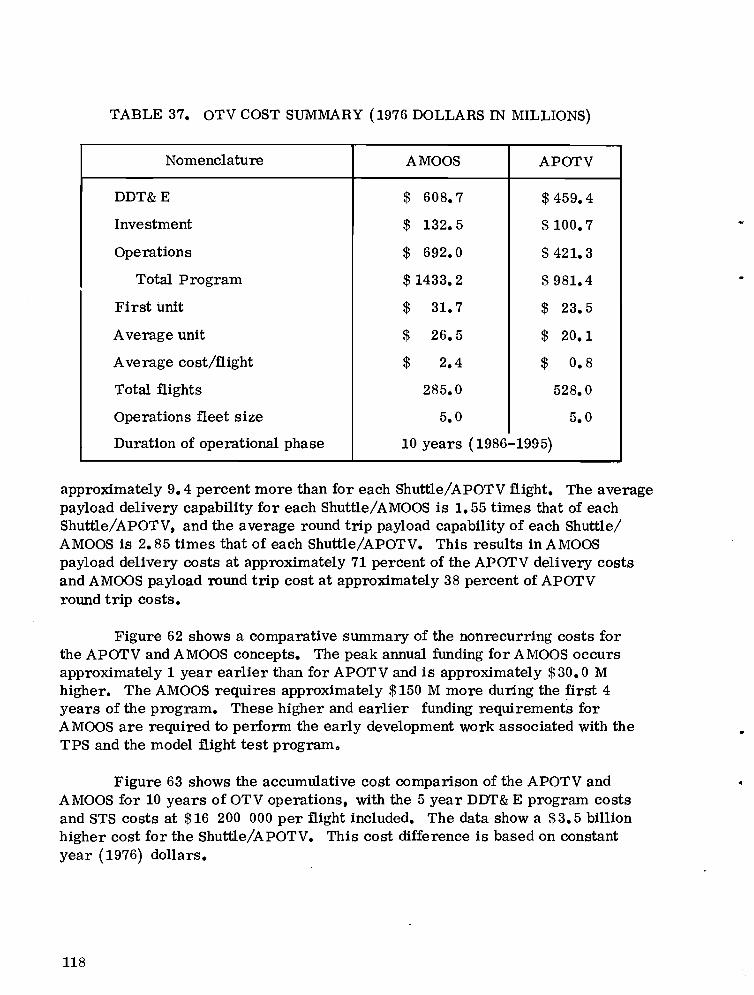
TABLE 37. OTV COST SUMMARY (1976 DOLLARS IN MILLIONS)
Nomenclature AMOOS APOTV
DDT&E $ 608.7 $ 459.4
Investment $ 132.5 $ 100.7
Operations $ 692.0 $ 421.3
Total Program $ 1433.2 $ 981.4
First unit $ 31.7 $ 23.5
Average unit $ 26.5 $ 20.1
Average cost/flight $ 2.4 $ 0.8
Total flights 285.0 528.0
Operations fleet size 5.0 5.0
Duration of operational phase 10 years (1986-1995)
approximately 9.4 percent more than for each Shuttle/APOTV flight. The average payload delivery capability for each Shuttle/AMOOS is 1.55 times that of each Shuttle/APOTV, and the average round trip payload capability of each Shuttle/ AMOOS is 2.85 times that of each Shuttle/APOTV. This results in AMOOS payload delivery costs at approximately 71 percent of the APOTV delivery costs and AMOOS payload round trip cost at approximately 38 percent of APOTV round trip costs.
Figure 62 shows a comparative summary of the nonrecurring costs for the APOTV and AMOOS concepts. The peak annual funding for AMOOS occurs approximately 1 year earlier than for APOTV and is approximately $30.0 M higher. The AMOOS requires approximately $150 M more during the first 4 years of the program. These higher and earlier funding requirements for AMOOS are required to perform the early development work associated with the TPS and the model flight test program o
Figure 63 shows the accumulative cost comparison of the APOTV and AMOOS for 10 years of OTV operations, with the 5 year DDT& E program costs and STS costs at $16 200 000 per flight included. The data show a $ 3.5 billion higher cost for the Shuttle/APOTV. This cost difference is based on constant year (1976) dollars.
118

..
•
180
AMAX == 58.9 (FY81). FIRST 4 YEAR A == 152.7
CI') (FY8O-FY83)2 1500::;... ~ 2 120 CI')
a: «...... 900 C <I:),.. C»... .... 60 2
~ 2 300 CJ
O~__~~__~____~____--'____--'____--'~____~ 80 83 84 85 8786
FISCAL YEAR
Figure 62. OTV program (comparison) nonrecurring cost summary.
12r---------------------------------~
CI') 102
2 I......
as , ~ 8
I A== 3.58 CI')
a: ,<t... I... 60 IC
APOTV), ~ C»... .... 4 )2 <t .... /CI')
2 /8 2 /
/.
o~____~__~~__~~__~~____~__~ 76 80 84 88 92 96 100
FISCAL YEAR
Figure 63. OTV program cost summary (comparison) including Shuttle transportation.
119

Because the AMOOS requires extensive early year funding, it was considered desirable to discount the expected costs at a 10 percent rate and to determine the comparative cost differences which result. Figure 64 shows this comparison. As can be seen the APOTV is $1.1 billion higher. The analysis for current year (1976) dollars and the 10 percent discount cases indicate that the crossover point for the additional AMOOS costs occurs in 1986 or 1987, or within 1 to 2 years after operations begin, and the AMOOS has the advantage from the cost point of view.
6~----------------------------------~
5
en Z 0 :; -' 4iii !!: en Irz: :3 I-' 30 / A·1.10
~ / I APOTV~/ ~
2; /8 " ",,"",.
o~____~__~~__~~____~____~____~
FISCAL YEAR
Figure 64. OTV program cost (discounted at 10 percent) summary (comparison) including Shuttle transportation.
Future OTV study effort should include further cost analysis. In addition to including those considerations previously mentioned, some analysis should address the high average flight cost of $2.4 M for A MOaS. Some SRT or some development effort in ablator refurbishment may result in savings in operations costs. Also, further effort in schedule and cost optimization Is desirable to assume a minimum cost OTV program.
120
E. Schedules and Cost for Planning Usage The schedules and costs previously shown were developed for OTV com
parison purposes. The OTV schedules and costs shown here should be used for future planning purposes. The schedules for APOT'V and AMOOS shown in Figure 65 represent approximately equal risks for either concept. The engine
• schedules previously given are appropriate. The nonrecurring program cost totals given in Table 37 are applicable. Howevert for the equal risk schedules t
the nonrecurring cost swnmary shown in Figure 66 should be used. Guidelines ... and assumptions (APOTV and AMOTV) for these schedules are:
1. Phase A study in FY-78/79; 12 month duration
2. Phase B studies in FY-80 (two parallel); 12 month duration
3. Phase C/D start in 3rd quarter FY-81
4. P& W RL-I0 liB engine assumed
5. Comparable schedule risk
6. Six months planned for Shuttle integration and launch preparation
7. One year flight test program (three flights) prior to IOC.
The APOTV planning schedule includes only nominal SRT t and there are no outstanding risk factors. A new engine development would extend the total program by 9 months. First vehicle delivery is 42 months after Phase C/D contract award (51 months if a new engine development is required). IOC is in July 1986 for the RL-I0 lIB engine assumption and in April 1987 if a new engine is required.
The AMOOS planning schedule includes extensive SRT with two model test flights scheduled for July and December ill 1980. Primarily, the risk assocIated with the AMOas is keyed to the predevelopment SRT and model test flight program achievements. Extensive ground test programs are scheduled in support of the vehicle design and development and for heat shield design and development efforts. A new engine development would not affect schedule planning which shows first vehicle delivery 51 months after Phase C/D contract award and IOC in April 1987.
The cost summary shows significant early year funding for the model test program for the AMOOS concept. The peak funding for AMOOS is slightly higher and approximately 1 year later for AMOOS than for APOTV•.
121

I-' t:>::> t:>::>
ALL PROPULSIVE OTV APOTV SRT (NOMINAL LEVEL)
PHASE A STUDY
PHASE B STUDIES (2 PARALLEL)
PHASE C/D PROCUREMENT
APOTV DESIGN 81 DEVELOPMENT CONTRACT
• DESIGN -TOOLING - FABRICATION, ASSEMBLY 81 CHECKOUT - MAJOR GROUND TESTS
LAUNCH SITE ACTIVITIES
FLIGHT TEST PROGRAM
IOC
OPERATIONS
AERO MANEUVERING OTV
(HEAT SHIELO. WINO TUNNEL. Ga.N.
••.I VEK.--lORT
CD 6 ': I I Eif> 8,I I I
C4)NCEPTI : SlflECTl<f\I I
I
AWARD RFP CONTRACT I to% DWO ~ RELEASE OEL
'.0<= ~ yo."I/>IClef f e~~. PDR CDy. #2
14'3..... F T I.(' I I
MODEL TEST FLIGHTS (2)
I --.. I I V V
«C .,"•• ASSY .. CIO ~ MAJOR GND TESTS
I !N\E~AU~CH 1ST FLT. TEST
\
IF~IGH~ TE~TS I 'V
I I~ I • IOPERATIONS i \.
AMOTV SRT AEROMANEUVERING. MOOEL FLT. TEST. ETC.) -I' ---YEH~'T
PHASE A STUDY
PHASE B STUDIES (2 PARALLEL)
PHASE C/D PROCUREMENT
AMOTV DESIGN 81 DEVELOPMENT CONTRACT
- DESIGN - TOOLING -FABRICATION, ASSEMBLY 81 CHECKOUT
- MAJOR GROUND TESTS
LAUNCH SITE ACTIVITIES
FLIGHT TEST PROGRAM
REFURBISHMENT
IOC
OPERATIONS
NOTE: P8IW RL10 CAT. liB ENGINE ASSUMED
tfl A ,
I ! H~ B 3 AWARD '''''" DWO I RFP CONT"ACTS "ELEASE DEL # :
: I
: tP
~ CID
I t
IPREL.IM PDRV PDR 1 VEH I DEL
<~ tF'·dISICN":':>.
# 2
: 166LI80 I
BEGIIjI HEIAT SHIELD a. -MODIlL TESTING I
· . ~
.?
/
MAJOR eND
~~ AS;
hI 3. 11 tl I LAUNCH
:R/EST I IN lEG I
1ST FLT
FLIGHT TESTS
V V V
I r:=::?gc OPERATIONS'"!----"'It.
Figure 65. OTV planning schedules (APOTV and AMOTV) •

•
U)
z 0 .... ...l 200 ...l
~ Z.... ~ 150 j ...l 0 CI ...0 100 r13' .... E-t Z « 50E-t U)
Z 0 u
..... N co
.
K AMOTV...,...
/' ~
/ APOTV~~ ~
If
~~~~ INCLU DES AMO rv MODE u TESTS
'" FY80 FY81 FY8Z FY83 FY84 FY85 FY86 FY87
"
Figure 66. OTV nonrecurring cost summary.
: ,
\
.
,

XIII. APOlV-AMOOS DESIGN COMPARI SONS
The APOTV (formerly Space Tug) and AMOOS concepts have been extensively studied by MSFC. The AMOOS efforts followed the APOTV activity and used, where appropriate, the results of the APOTV design efforts. The APOTV background primarily addressed unmanned payloads, and the AMOOS study has addressed manned capability. The AMOOS studies have mainly addressed problems peculiar to the aeromaneuvering aspects of the system. The APOTV definition, particularly in detailed design, is much more advanced than AMOOS.
While there are differences in the complexities and level of understanding of APOTV and A MOOS, there are no "show stoppers" expected for either concept. The comparisons which follow are illustrative of the differences and concerns related to each concept and should be useful for costing the two concepts and for future activity planning.
In Pre-Phase A activities, $578 000 and $291 359 have been spent on contracted studies on the APOTV and AMOOS, respectively. In the Phase A type contracted efforts, $400 000 has been spent on APOTV and $ 50 000 on AMOOS. No Phase B contracted activity has occurred for the AMOOS vehicle; $1 635 115 has been spent on APOTV.
It is difficult to compare the status of maturity of the two concepts because the requirements and payload capabilities have changed significantly since the major portions of the APOTV studies were performed. Also, a portion of the APOTV study effort and advanced development is directly applicable to AMOOS. The desire to improve the Shuttle payload capability and maintain the current cargo bay length will probably require new unique design approaches for either case.
It seems fair to say that, up to and including significant portions of the Phase A definition efforts, the two concepts are comparable in definition and maturity; thereafter, the AMOOS definition is less than APOTV. This is particularly so in areas such as internal arrangement, specific conceptual design detail of structural closures, TPS (ablative shield) refurbishment, and problems associated with the small atmospheric reentry corridor necessary for AMOOS. Also, problems associated with communication systems, RCS, and their protection during reentry have not been addressed for AMOOS.
124

A. Detailed Layout - Design Comparison 1. APOTV. For the most part, the APOTV design is relatively mature
and few issues exist. Problems associated with Shuttle improvements, interfacing with the Orbiter, payloads, Space Station, etc., are issues.
2. AMOOS. AMOOS studies have primarily addressed the external configuration aspects of the OTV. Generally APOTV internal arrangements, etc., have been used, and as a result no AMOOS optimal design exists. Internal arrangements (in-board profile, structural, propulsion, avionics details) are of concern. Center of gravity/center of pressure relationships and general aerodynamic evaluation for range of payloads and reentry configurations are needed. Engine arrangement and related door openings and sealing problems are issues. Problems associated with Shuttle improvements, interfacing with the Orbiter, payloads, Space Station, etc., are issues.
B. Propu Ision The APOTV and AMOOS concepts studied here use essentially the same
main stage propulsion system. Lox and hydrogen have been used as principal engine propellants. Very little effort has been expended on the Earth or space storable systems.
Differences in the RCS of the two concepts are reasonably well known. No problems are anticipated for either in a propulsion sense. The AMOOS requires a rather high thrust (200 lbf) during reentry, and the arrangement and protection of the system are problems.
Comparison of the APOTV and AMOOS for propulsion problems associated with two staging, long orbit stay time, higher mixture ratios, and other problems associated with the OTV mission capture have not been investigated; however, few if any problems are expected.
C. Structu res 1. APOTV. Due to the high velocity requirements required by the APOTV
type system, weight is a very critical factor. Quite exotic and advanced designs are needed to obtain reasonable and competitive payload capabilities with APOTV. The configuration aspects of the APOTV are significantly more simple or conventional than AMOOS.
125

2. AMOOS. The AMOOS uses aeromaneuvering/braking with an ablative heat shield which reduces the propulsive velocity required by 25 to 28 percent when compared to APOTV. For this reason the AMOOS has significantly more payload capability, and structural system weight is much less critical. The AMOOS, however, requires a very unconventional structural design in configuration and environment. The AMOOS structure experiences the cold environment of the cryogenics and the hot environment of the atmospheric reentry. It is to be expected that the structural problems of AMOOS are significantly greater than APOTV; for example, the tank support structure must be designed to absorb large thermal gradients. Although most of the structural concepts for AMOOS are current state-of-the-art, they are representative of innovative applications of these arts. .
D. Thermal/Thermal Control Thermal control for cryogenic tankage is the same for the APOTV and
AMOTV with slightly more insulation being required for AMOOS. The proposed protection systems seem adequate for up to 7 day systems. Since the previous Space Tug studies, the requirement for up to 30 day sortie missions has been added, and very little is known about the resulting tankage insulation effects. This is an issue which must be addressed in future definition of either system.
1. APOTV. The thermal design of APOTV is relatively simple when compared to AMOOS. Significantly less refurbishment is expected as the APOTV has no heat shield and few sealing problems.
2. AMOOS. The AMOOS has an ablative heat shield covering the entire external surface. The proposed shield material is current state-of-the-art as manufactured by the Martin Marietta Company (MMC) for the Viking program. Sealing problems are expected for the openings and closures of the external surface. Significant problems associated with refurbishment or replacement of the ablator are expected.
E. Guidance, Navigation, and Control Basically the guidance, navigation, and control (GN& C) problems of the
APOTV and AMOOS concepts are the same for all maneuvers prior to the maneuvers which place the OTV in Shuttle compatible rendezvous orbits. Simplified flight profiles depicting these maneuvers are given in the Flight Profile Section. The first significan~ difference, which affects GN& C, occurs as the OTV's are approaching the insertion window at perigee (APOTV) or
..
126

atmospheric reentry corridor (AMOOS). The APOTV requires only a 15 n. mi. constraint on the Orbiter compatible rendezvous orbit while the AMOOS has a ±2 n.mi. constraint on the atmospheric entry corridor. The AMOOS contractort LMSC t has studied this problem and recommends a sextant type system composed of two star trackers and a horizon system for use on the AMOOS.
The AMOOS requires an additional guidance law for the aerobraking maneuver. An additional 5000 words of software are required for AMOOS. This is compared with APOTV.
As the AMOOS ascends from the atmosphere after the atmospheric maneuvert 1he perigee must be raised so that the AMOOS does not enter again on the next orbit. This maneuver must be made in less than 45 min after atmospheric exit which causes an issue at the approximate time for tracking or position, updatingt etc. It may be necessarYt or desirable, to perform an additional propulsive maneuver here to circumvent these problems. The additional maneuver would be predetermined but only for the purpose of raising perigee and could be initiated by a timer. The AMOOS would then accommodate the 15 n. mi. constraint Shuttle Orbiter compatible rendezvous orbit.
F. Communication and Data Management There have been no principal differences identified in the communication
and data management subsystems for APOTV or AMOOS except that computer memory must be increased by 5000 words to accommodate the increased guidance and navigation capability for AMOOS. There are, however, differences in operations applicability and subsystems design due to the atmosphere maneuver of AMOOS. These are as follows:
• Ports in vehicle to allow antenna deployment (e. g., communications, docking, etc.)
• Deploy/retract mechanism for antennas and control system.
• Plasma sheath problems (if communication is required during the atmospheric maneuver) •
G. Performancel Capabi lity Compa ri son A performance/capability comparison for the APOTV and AMOOS con
cepts is shown in Figure 67. As can be seen, it is increased performance/ capability which makes the AMOOS desirable. The payload retrieval shown
127

I--' IS) 00
iii... <:>
~ Q... :!: w ~ ..J... Q Q « 0 ..J >« c..
28
24
20
16
12
8
4
0
()
125 P.4"l0.40
lOX/HYDROGEN PROPELLANTS
11£1"111£"£0 ( o 1~(~
Cb
iii ~
g !'.: L () ~ 125t' w ,
~ \ ~ ~ 100 ~ c tc" U) \ ',\ , 1)0
65" ~ ,\,
NOTES
, \' \ , 4'0
,~'\V~ I APOTV , )i'
"'~ MAX. ROUND TRIP
1 SINGLE SHUTTLE LAUr:CH WITHSTAGEA~DPAYLOAD
CARRIED m; SA·.~c SHUTTLE 2 2.9:; SHUTTLE TARE
WEIGIIT A:;SU~.~cD
RETRIEVE ONLY CAPABILITY
APOTV 65KSHUTTlE
125K SHUTTLE
AMOOS 65K SHUTTLE
125K SHUTTLE
4,900 LB 9,100 LB
-I 1<;,500 LB - 34,700 LB
Figure 67. Geosynchronous orbit capability comparison.
..
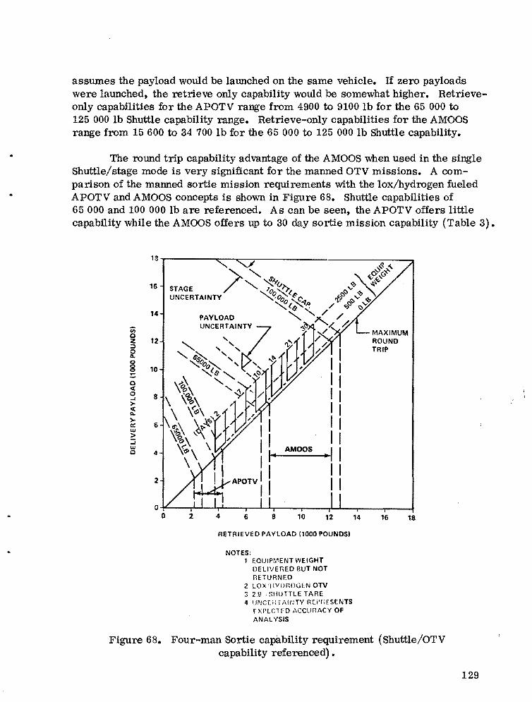
assumes the payload would be launched on the same vehicle. If zero payloads were launched, the retrieve only capability would be somewhat higher. Retrieveonly capabilities for the APOTV range from 4900 to 9100 lb for the 65 000 to 125 000 lb Shuttle capability range. Retrieve-only capabilities for the AMOOS range from 15 600 to 34 700 lb for the 65 000 to 125 000 lb Shuttle capability.
The round trip capability advantage of the AMOOS when used in the single Shuttle/stage mode is very significant for the manned OTV missions. A comparison of the manned sortie mission requirements with the lox/hydrogen fueled APOTV and AMOOS concepts is shown in Figure 68. Shuttle capabilities of 65 000 and 100 000 lb are referenced. As can be seen, the APOTV offers little capability while the AMOOS offers up to 30 day sortie mission capability (Table 3).
13
16
14
Cii 0 z 12 :;:, 0 "0 0 0. 0 « 0 -l >« ">a:: w > -l W 0
10
6
4
2
AMOOS
MAXIMUM ROUND TRIP
RETRIEVED PAYLOAD (1000 POUNDS)
NOTES: 1 EOUIPMENT WEIGHT
DELIVERED BUT NOT mTURNED
2 LOX '1IYDROGlN OTV 3 2.9 . SHUTTLE TARE 4 UNC[inA!~lTY RLt'f,[SENTS
[XPlC1EO ,\CCUf1ACY OF ANALYSIS
Figure 68. Four-man Sortie capability requirement (Shuttle/OTV capability referenced) •
129

XIV. DI SCUSSION OF THE OTV PROGRAM OPTIONS
As previously mentiqned, the OTV analysis data have been parameterized for Shuttle capabilities ranging from 65 000 to 125 000 lb. This section deals with identification and discussion of various options within this Shuttle capability range. The options deal primarily with lox/hydrogen OTV concepts; however, limited discussion with space/Earth storable systems is shown.
A summary of payload transfer capability requirements is shown in Table 3. These capabilities may be expected to change somewhat as more development is completed. It is, however, expected that they are representative of the future needs and that they will change only by a small percent. Also, when an OTV concept together with a corresponding improved Shuttle capability is selected, the payloads can be expected to be designed to conform with the transportation capability.
A. Lox/Hydrogen Propellant Orbit Transfer Vehicles
Twelve options for the single Shuttle stage and dual Shuttle stage OTV are discussed. The single Shuttle stage concepts involve only one Shuttle launch, and the payload and OTV are carried to low Earth orbit in the same Shuttle. For the dual Shuttle stage case, a stage sized for single launch has been used, and one stage and one-half of the payload are carried to orbit on each of two Shuttles •
. Summary payload requirements and capabilities are shown in Figures 69 and 70. Figure 69 shows the delivery only case, and Figure 70 shows round trip· capability. Figure 71 shows similar summary in simpler form.
1. 65 000 lb Shuttle Capability Options. For the single Shuttle stage cases, neither the APOTV nor AMOOS satisfies the required capabilities. The AMOOS does, however, provide limited capability for manned transfer.
For the dual Shuttle stage cases, the APOTV does not adequately provide capability for sortie missions. The AMOOS provides capabilities to perform all missions except the fully assembled stations.
2. 100 000 lb Shuttle Capability Options. For the single Shuttle stage case, the APOTV still does not meet any of the capability requirements. It may nearly meet the four-man crew transfer requirement. The AMOOS single Shuttle stage, however, meets nearly all of the requirements except for the fully assembled station.
..
130
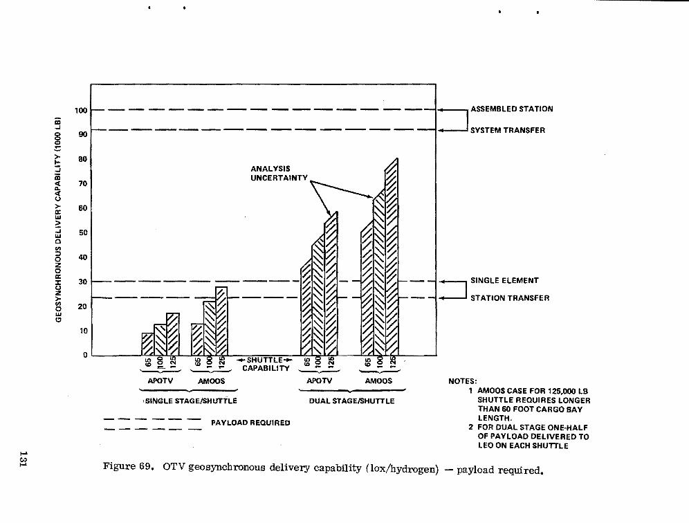
I-' C..:> I-'
iii ..J
g :: > I:::; Cii « ~ Co)
>a:: w ~ ..J W a en :l o Z o a:: ::r: Co) z > ~ w (!I
100
90
80
70
60
50
40
30
20
10
ANALYSIS UNCERTAINTY
o ' •r" > I , I " < I i! r= I
- .... itS l8 0 ~ -SHUTTLE '!"-'d''f... ' ".c!~'6s' ~ CAPABILITY
APOTV AMOOS APOTV
SINGLE STAGEISHUTTLE DUAL STAGEISHUTTLE
PAYLOAD REQUIRED
---, ASSEMBLED STATION
----1 SYSTEM TRANSFER
---, SINGLE ELEMENT
-----1 STATION TRANSFER
NOTES: 1 AMOOS CASE FOR 125,000 LB
SHUTTLE REQUIRES LONGER THAN 60 FOOT CARGO BAY LENGTH.
2 FOR DUAL STAGE ONE-HALF OF PAYLOAD DELIVERED TO LEO ON EACH SHUTTLE
Figure 69. OTV geosynchronous delivery capability (lox/hydrogen) - payload required.
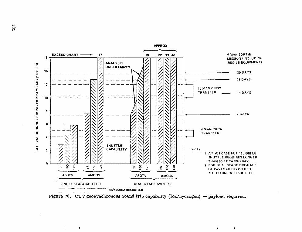
_ _ _ _ _ _
---------------
.... t.:l I:\:)
APPROX.
EXCEED CHART - 17 18 22 33 40 4 MAN SORTIE 16 MISSION (IN": UDING/.
2500 LB EQUIPMENT)%ANALYSIS % % ~ /. ..,I ,,, ~ UNCERTAlNTY ~ /; ~ ~= ° 30 DAYS--'%------ %_-~~%° !:° ~--- ~ ~~%-----.-----
~1 DAYS0 - - -- -- - ---~% -- -- - // ~ c "" // ----- %--~~%---."" % ---120 ..,I ~~ ~%--~~~--JC 14DAYS> ._____ ==I~~----- ~~ /j~~ 12MANCREWQ. ~ /; _____ ~ /; :::% ~ /; ::, TRANSFER_!: 10 c I ~~ ~~ ~~% ;0 z ::;) II _______ ~~,--- - ~~ ~~~ I 7 DA'(S0 IX: ~~~I -~~~ --I~~~--i-'---~
0 6 z ::;)
,----%-_~~~I___- ~~~ I~~I~0 IX: ___ ~--~~~ _____ ~~~--I~~I~I--I 4MAN':REW::c u 4 ~ ~ ~ ~ ~ _:~ ~ ~ -_I~ ~i~ --:J TRANSFERZ > ~ %~~ ~~~ SHUTTlE :~~% '~~10 '-?"" 2 %~ ~ ~ ~ ~I CAPABILITY 1% ~ ~ !~ ~.~ I
AMUUS CASE FOR 125.000 LB SHUTTLE REQUIRES LONGER THAN 60 FT CARGO BAY
;;;~~ ~~~' ~~~ I~~% i ~(}q- - -' %~~ /j~~
t.O e t.O &n0.o ltI:::>t.O 2 FOR DUA STAGE ONE·HALFII)tr: ° e_ '" N...
<C~~.~ ° N - ...... tD~~ OF PAYLOAD DELIVERED-,.~ TO EO ON E A ~H SHUTTLE
0 --- -.APOTV AMOOS APOTV AMOOS
'----------~---------SINGLE STAGE/SHUTTLE DUAL STAGE!SHUTTtE
- -- -- -- -- PAYLOAD REQUIRED
Figure 70. OTV geosynchronous round trip capability (lox/hydrogen) - payload required.

SINGLE SHUTTLE/STAGE
RfW
'" '" > TRANSFER 00 ~~ Z ... CREW SIZE " Z I otoO::l Go ;: ~ -2' ... 0 ... 1-", 4 12 >i!: u "'" "'" ...... 1-'" ,,;Ii !ill" > z "'w "'''IL I 0 ::> 0... - u 0 ..J = >I- ell I1-" 0:::>IL 3:3 g8 II gO 8 0
.. § 08 ~ g r.. ...-
>
8 ~ ·ii! 8'" x ~·,
00 ~.,., 0 8 10;? x x!
8 ~ . x
c "' Cil c'" ~
~ x )( x
DUAL <;Hl'TTtE STAGE
i; (~
~ 0 )( X ~
'" ~ X X• )(·>
0 ~ X )( )(
g 0 !l0- 0 )( X X;
., 1 x X l<. 8 '" Q)~N
X- {' X x
WEIGHTS POUNDS
4 MAN SORTIE
7 DAY 14DAY 21DAY
"iIi::lIS "iIi::lg "il~:::>1& ",I i::liS ~I~ ~II (j) 0 I<D (Y (j) ®
i 8 88 ~~ g ~ j§ 8 0 0> ... .. 8
'" ;Z CD '" ~ 0> --M_---
x
x x )( x x 0
•. )( x x x x
)( )( @
)( X X )( X X
)( )( )( X X X
\( X X X X )(
X X l<. )( X X
X x x x x x
JODAY
~II ~I~~Ig ~ ~
§! II.....-- -
I
0 I
X x I
X X
)( @
X )(
X l(
x )(
'--
!-l c:.:l c:.:l
LEGEND - )( MEETS REOUIRED VALUE --- -®NEARL Y MEETS REOURED VALUE
N°lEI~CLUDING 500 LB PAYLOAD EOUIPMENT
q. INCLUDING 2500 LB PAYLOAD EOL'IPMENT (J). REOUIRES CARGO BAY LENGTH GREATER
THAN 60 FEET LONG
'" FOR SINGLE SHUTTLE/STAGE CASE THE PAYLOAD AND STAGE IS CARRIED ON SAME SHUTTLE
S; FOR DUAL SHUTTLE/STAGE CASE.2!!!5.. STAGE AND OlliE-HALF OF THE PAYLOAD IS CARRIED 0111 EACH SHUTTLE
Figure 71. Capability comparison lox/hydrogen OTV.

For the dual Shuttle stage cases, the APOTV and AMOOS provide the required capability except for the fully assembled station. The APOTV can only perform sortie missions of 14 days duration.
3. 125 000 lb Shuttle Capability Options. For the single Shuttle stage case, the APOTV provides only four-man transfer capabilities. The AMOOS single Shuttle stage case meets all requirements except the fully assembled station.
For the dual Shuttle stage cases, the APOTV and AMOOS provide the required capability except for the fully assembled station.
4. Comparison of APOTV and AMOOS. For the single Shuttle stage cases, the 125 000 lb Shuttle capability is required for APOTV to meet approximately the same capability the AMOOS provides with a 65 000 lb Shuttle capability. For the dual Shuttle stage cases, the 100 000 Ib Shuttle capability is required for APOTV to meet approximately the same capability the AMOOS provides with a 65 000 lb Shuttle capability. There is no single Shuttle stage APOTV option which provides the required capability.
5. Shuttle capabilities. The 65 000 Ib Shuttle capability is not adequate for meeting orbit transportation requirements in single or dual operations flights if the APOTV option is to remain open. A Shuttle capability of approximately 100 000 lb is needed to make both OTV options viable.
The 100 000 lb Shuttle option, with the AMOOS, is the minimum capability needed to meet the transfer capabilities required with single Shuttle stage operations. It is noteworthy that this combination is the maximum capability which can be accommodated with a 60 ft long cargo bay.
6. Single Shuttle/Dual Stage Options. Data for dual stage in a single Shuttle option for the APOTV and AMOOS are presented in the Performance Capability Section. The dual stage cases provide only modest improvement over the single stage cases. It is expected that cargo bay length problems associated with dual stages would eliminate this small advantage in performance. A stage plus drop tank case is also shown. The drop tank case is not significantly better than the dual stage case even though the drop tanks were expended. Dual stage or stage plus drop tanks in the same Shuttle are not attractive options for the lox/hydrogen propellant stages.
134

B. Space/Earth Storable Propellant OlV Capability data for lox/RP and N20 4/MMH propellant APOTV and AMOOS
are shown in the Performance/Capability Section.
For the APOTV, neither propellant combination provides the needed orbit transfer capability in the single Shuttle stage case. The APOTV with N20 4/MMH provides negligible, if any, capability. The data indicate that, in the single Shuttle/stage case, the AMOOS with lox/RP propellant is attractive for Shuttle capabilities exceeding 125000 lb. N20 4/MMH for the single Shuttle stage AMOOS is much less attractive.
Dual Shuttle stage options using the space/Earth storable propellants have not been studied.
XV. TECHNOLOGY REQU IREMENTS
Technology development for OTV has been underway for several years. Some requirements were identified in the early Space Tug activity and development has been started. The requirements which follow were identified in a recent study or were identified earlier and development was not started or was not finished.
A. Aerodynamic! Aerothermal The AMOOS concept requires an aerodynamic configuration which uses
an ablative heat shield to reduce the propulsion requirements of the OTV. Hypersonic wind tunnel testing is required to determine:
1. Loads
2. Aeroheating parameters
3. Configuration optimization
4. Ablative shield optimization.
A model test program has been proposed which would verify the results of this effort. The model would be taken to the appropriate orbital location on an early STS flight and would be released to perform essentially the same aeromaneuvers which are expected for the AMOOS.
135

B. Ablative Heat Sh ield A Viking type ablative heat shield has been proposed for the AMOOS
concept. Required technology development is as follows:
1. Shield optimization (weight minimization)
2. Shield refurbishment
3. Sealing (closures)
4. Antenna protection
5. Higher permissible bond line temperatures.
For the long term, a reusable (nonablative if possible) heat shield is desirable. Recent study indicates such a shield is not practical in the 1980 to 1981 timeframe. This technology should proceed with the intent to replace the ablative shield which will be used in early OTV applications.
The A MOOS costing analysis indicates that heat shield refurbishment is a predominant portion of the AMOOS operations cost. The AMOOS operations cost is $1.6 M more than APOTV per OTV flight on an average basis. Technology development aimed at reducing the estimated cost of the ablative shield refurbishment is desirable and will probably prove to be cost effective.
c. Subsystem Hardware 1. Structures. Recent OTV payload capability requirements are higher
than were previously determined. Shuttle capability improvement with the current Orbiter cargo bay, which is 60 ft long, is highly desirable. Previous OTV efforts have utilized rather conventional structural/configuration/tankage concepts which limit the usage of improved Shuttle capabilities. OTV structural technology development should be extended to include:
a. Nestled or common bulkheads
b. Low profile bulkheads
c. Tapered/ogival tankage.
136
2. Propulsion. The propulsion (engine) options for OTV are covered in other sections of this report. The ongoing technology efforts for anew, high performance engine system are desirable and should be continued. A short engine length is needed.
In addition to the ongoing engine technology development, the requirement for the engine to operate at varying and higher oxidizer-to-fuel mixture ratios has been identified. Current lox/hydrogen engine development efforts (ASE) are aimed at oxidizer-to-fuel mixture ratios over a 5: 1 to 7: 1 range. Development of engine systems which operate at 6:1 to 7:1 (and higher) is needed. In order to provide parametric data for further OTV systems trades in studies related to orbit stay time of the OTV, technology development is also needed on a dual fuel type engine. The dual fuel combination would use lox and LH2 in one mode and lox and some type of space storable fuel in a second mode using the same engine system.
3. Communications. Previous communication system development for OTV has centered primarily on systems for use with the APOTV concept. To also accommodate the AMOOS concept, the following requirements are added:
a. Investigation of plasma sheath problems during the atmospheric maneuvers.
b. Protection of antenna during atmospheric maneuvers.
4. Guidance and Navigation. Previous guidance and navigation system development for OTV has centered around systems for use with the APOTV concept. To also accommodate the AMOOS concept the following requirements are added:
a. Further development of guidance concepts for the atmospheric maneuver.
b. Development of an autonomous navigation system which will provide a 0.5 n. mi. accuracy to meet the atmospheric entry corridor.
5. Tank Insulation. For the most part, previous OTV tankage insulation concepts for lox/hydrogen systems provided the capability for 7 day missions. To perform man-sortie missions with orbit stay times up to 30 days, insulation concepts need improvement.
6. Miscellaneous. The following systems, unique to the OTV, are required to provide interface capability with other STS and payload hardware.
a. Shuttle support/deployment/retrieval mechanisms.
137

b. Servicer/manipulator systems
c. Docking mechanisms/adapters.
D. Pumping of Liquids in Space The current OTV design accommodates only ground based loading of
fuels. In the long term, it may be desirable to fuel or refuel the OTV at various orbital locations. Development of the capability for the handling and pumping of liquid fuels in space is needed.
E. Summary Technology Requi rements OTV technology requirements are summarized in two categories in
Table 38. The first category includes requirements on which technology development efforts have been completed or are ongoing, and in the second category are requirements on which technology development efforts are needed and should be initiated.
TABLE 38. OTV TECHNOLOGY REQUIREMENTS
Ongoing (or Completed) at MSFC
• Structures • Electrical Power - Light Weight Tanks - Fuel Cells
• Communications - Solar Arrays - Phased Arrays • Computer
• Guidance and Navigation • Materials (General) - Laser-Gyro IMU - Lubricants - Laser Radar • RCS/Attitude Control
• Thermal Control • Radiation Hazard Instrumentation - Component (Electronic Equipment • Slush Hydrogen
Internal - Heatpipes) - Instrumentation - Radiators - Test - Tank Insulation • Propulsion (also ASE at LeRC) - Component/Cryogenic Interface • Aerodynamic for AMOOS Shaping - Testing • Aerodynamic and Load Testing (LeRC)
Needed
• Aerodynamics/Aerothermal • Communications - Loads - plasma Sheath - Aeroheating - Deployable/Retractable System
• Configuration Optimization • Guidance and Navigation Structures - Autonomous Navigation (Reentry - Nestled and Flat Bulkheads Corridor) - Tapered/Oglval Tankage • Tankage Insulation
• Heat Shield - 30 Day Sortie - Ablative (Near Term) • Propulsion (Lox/Hydrogen) - Shield Optimization - High Performance at Variable - Shield Refurbishment Mixture Ratio and Dual Fuel - Sealing and Closures • Mechanisms - Antenna, etc. Protection - Shuttle Deployment and Retrieval - Reusable (Far Term) - Docking/Berthing/Adapting
138
XVI. SUMMARY
A. Backg rou nd The problems of orbit transportation have been addressed significantly
during the past 5 years. An IUS and SSUS are being developed for operation in the early 1980's. Current long-range planning efforts indicate a need for extended space operations capabilities which are greater than those provided by IUS and SSUS.
It is primarily the developing need for Earth synchronous orbit capabilities which gives cause for further consideration of OTS at this time. Transportation needs for manned and unmanned synchronous orbit systems are foreseen. Total recoverability and reusability with minimum refurbishment are goals for future OTS.
B. Introduction To establish a common basis for identifying current transportation con
cepts, an OTV is defined as a propulsive (velocity producing) rocket or stage. When used with a crew transfer module, a manned sortie module, or other payloads, the combination becomes an OTS. Standardization of OTV's and OTS's is required.
c. Study Approach As previously mentioned, significant technical and planning information
for OTV concepts has been previously developed. These data were assembled, new ideas were introduced, and problem area identification was extensive and wide ranging. These are summarized as issues:
1. Mission goals
2. Interfacing transportation and space hardware elements
3. Technology availability
4. Minimizing the number of OTS elements required
5. Flexibility for operational applications and future growth capabilities.
139
To determine the effect of these issues, typical mission scenarios were developed and typical OTV and OTS concepts were introduced to satisfy these missions. o.TV and Shuttle capability data were parameterized to cover the range of transportation requirements occurring in the scenarios.
D. Significant Early Findings Earlier preliminary findings in the study indicated that the current
65 000 lb Shuttle capability was insufficient to meet the orbit transfer requirement if single Shuttle launch concepts were to be viable. Previously, dual and triple Shuttle launches had been proposed; however, these concepts presented significant operational problems, low transportation system efficiency, and presented significant problems with payloads.
In this study, data have been developed for the 65 000, 100 000, and 125 000 lb Shuttle capabilities. These three data points give parameterized possibilities over the range from 65 000 to 125000 lb low Earth orbit capabilities.
E. Orbit Transfer Transportation Requirements There are several documents available from which orbit transfer require
ments may be derived. These are the 1973 and 1976 Shuttle mission models, the 1976 Space Industrialization project/element model, the 1975 geosynchronous orbit Space Station options study by MSFC, and misccllaneous 1976 planning data. These references were used to determine a Nominal Program Option and a Low Program Option. The Nominal Program Option included a 4-man geosychronous orbit station operational capability in 1987, 8-man in 1989, 12-man in 1991, and the capability to add one 12-man system per year after 1995. An lILLV was assumed for operational availability in 1992. The Low Program Option assumed that the space power program would be delayed and that the geosynchronous orbit four-man station capability would be delayed until 1989. The station was assumed to be increased in size to accommodate a four-man visit for short periods after 1991. No HLLV was assumed for the Low Program Option.
The Nominal and Low Program Option requirements are summarized in Tables 5 and 6. Cargo type payloads to synchronous orbit are shown as weight to be transported, and other payloads are shown as specific mission flights.
The nominal programs include a 4-man crew transfer capability prior to 1992 and a 12-man crew transfer capability after 1992. The Low Program Option includes only a four-man crew transfer capability, and both options
140

•
include a four-man sortie capability. The sortie capability provides significant program flexibility but is probably more important in the Low Program Option. Lunar, planetary, etc., capabilities are also included. It is noteworthy that only a small percentage of the current Shuttle missions are included.
The requirements previously shown are representative of expected OTV missions for the 1986 to 1995 time period. For OTV consideration, it is necessary to know the weight characteristics of each particular type payload to be transferred.
Table 3 shows the OTV payload capability requirements which were derived in this study. For this study it has been assumed that between 500 and 2500 Ib of equipment would be needed on sortie missions.
F. ON Configu rationsl Concepts Concepts studied for the OTV and manned carriers are shown in Figure
72. An APOTV (formerly Space Tug) and an AMOOS (sometimes referred to as AMOTV) concept have been studied and compared. Crew transfer and fourman sortie modules have also been studied.
The OTV concepts shown in Figure 72 use lox/hydrogen propellants. Lox/RP, N20 4/MMH, and solid propellant systems have also been studied. Parametric configuration data for 65 000 to 125 000 Ib Shuttle capabilities were developed.
G. Weight Data Weights for the liquid propellant APOTV and AMOOS concepts which were
studied are shown in summary form in Figures 73 and 74. Weights for the manned systems are summarized in Figure 75. Weights were also calculated for expendable drop tanks for OTV usage and for expendable solid motor applications. These can be found in the Main Weight Data Section and the Performance Section of this report.
Weights were calculated for selected OTV propellant loadings to provide parametric data over the range of Shuttle capabilities being considered. Weights were calculated for the manned systems to give the particular mission capability which was desired.
141
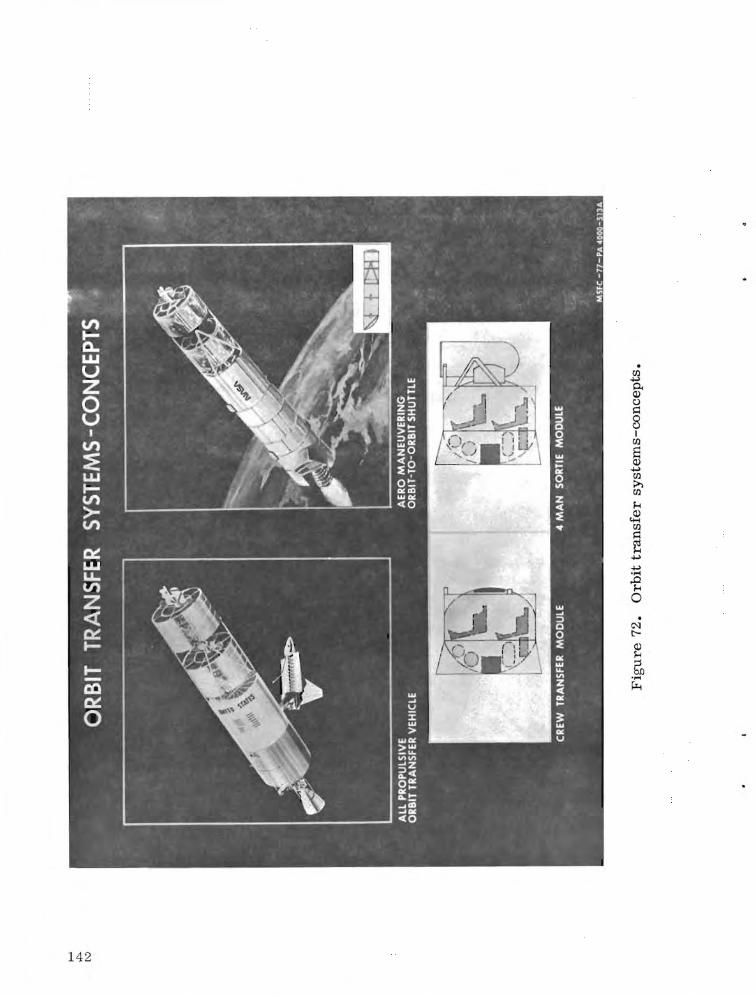

•
• VEHICLES FOR USE WITH SHUTTLES CAPABLE OF CARRYING 65 TO 125 K POUNDS
LOX/HYDROGEN LOX/RP1
APOTV I '~ .." ..-- 99,865I,PROP LOAD@ 99,248 -C1 C1"
4561 2068 I
~APOTV I \t 11{1\ ~ 52,394PROP LOAD @ 83,255 J --- C1" 20182316
3530 ... 1280· 437 PROP LOAD @ 5O,la9LB APOTV-BASELINE ',t
. I 1\ I~ 867 · ----....--- 1346 9211859
• STRUCTURES 1947 243
1028 · --------68, . 921 ~• PROPULSION 1346 -·-977 -10001 -~ • THERMAL 441
4160 -• AVIONICS 924
8032
% GROWTH -TOTAL SYSTEM DRVWT 5150
..... ,;:.. C;:) Figure 73. All propulsive orbital transfer vehicle weights (APOTV).
N204/MMH
~ ~ " ""I 12420
2018
1273 408
1346 921
213 ..... 6344921
.,...... 4128
~
-
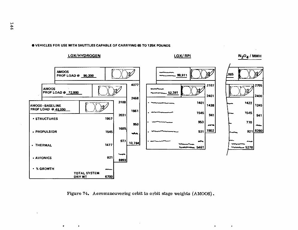
I-' ~ ~
• VEHICLES FOR USE WITH SHUTTLES CAPABLE OF CARRYING 66 TO 125K POUNDS
LOX/HYDROGEN
AMOOS PROP LOAD @ 90,200 r ·-"""""'-'~, \: "
c' •
r,"" __ ,,/!r-.....I
AMOOS PROP LOAD @ 72,000 (-~-- L.'~I. '\."
\." ..\r", ___ ,' r...,'
4077
AMOOS-BASELINE PROP LOAD @ 48.500
• STRUCTURES
• PROPULSION
• THERMAL
• AVIONICS
r ----- ~'?' '\ ~ ..":t I
t,, ____ ,' ......,,'
1957
1545
1477
921
-• % GROWTH TOTAL SYSTEM 6700 DRYWT
2468 3100
1861 2031
950 1685
~
977. 10,784
-8893
LOX/RPI
in,. .... ,., AI 2107
- 52391 ........ ' c-'v 12401"""".,- • ...... --' r
·~Ioi .. "" • -_.... ""l1lI
.-----
1401. 1438
1545 941
953 -921 17802
--~5461
Figure 74. Aeromaneuvering orbit to orbit stage weights (AMOOS).
N20 4 /MMH
1422 , 1245
1545 941
770 -921 18260
-

---------- ---- -------- ------- -------------
-----
•
MANNED SYSTEM WEIGHT ANALYSIS 4 MAN SORTIE WEIGHT REQUIREP
TRANSFER MODULES r 30 DAY MISSION
r 21 DAY MISSION
OJ I 14 DAY MISSION
7 DAY MISSION4MAN
ITEM WEIGHT
STRUCTURES 1598 CREW FURNISHING 3:25 CREW EQUIPMENT 1470 ELECTRICITY 935
12MAN ~l' a
CABIN PRESSURIZATION 130 CONTROLS (RCS) 60f· r' EXPENDABLES 340.k ' 1'" •<I 10% GROWn" ..JWi.
TOTAL 5344
CREW TRANSFER
CREW VOL WEIGHT SIZE (FTS) (LB)
4 585 4062
12· 1033 10,500
$REF LMSC 1977
4 MAN SORTIE VOLUME tCUFT.I
STRUCTURE CREW SYSTEM ECLSS .E..!:,E£.TI!LC!L_
7 DAYS 14
DAYS 21
1008 1223
!.!!!. 1630
~-
7874
~
~
-8978
"---.c
~
~
~
~
-~
10,251
4 MAN SORTIE MISSION
7 DAYS
30 DAYS
~ >+>Cll
Figure 75. Weights for manned systems.

H. OlV Flight Profi les Simplified mission flight profiles for the APOTV and AMOOS concepts
are shown in Figures 76 and 77. The profiles shown are for single Shuttle stage operations. The principal difference in the profiles of the APOTV and AMOOS occur wheI the vehicles are returning to Earth•. The APOTV performs a propulsive retromaneuver, and the AMOOS enters and maneuvers in the atmosphere using an ablative heat shield to brake the vehicle. It is this maneuver that gives the AMOOS a significant performance advantage. The maneuver reduces the AMOOS velocity requirements by over 7000 ft/sec.
The OTV flight profile will have a significant effect on the stage subsystem requirements. Previous studies in this area addressed different mission parameters than are currently envisioned. The determination, analysis, and selection of the OTV mission profile are issues which should be given high priority in the near future.
I. OlV Performance Capabi lities Performance calculations were made for lox/hydrogen, lox/RP, N20 4/
MMH, and expendable solid motor concepts. The staging effects, i. e., single stage, dual stage, or drop tank plus stage, were also investigated. Staging effects for the lox/hydrogen APOTV and AMOOS concepts are shown in Figure 45. A 100 000 lb Shuttle payload capability was assumed for this analysis. It should be noted that all dual stage and drop tank configurations exceed the 60 ft cargo bay length.
Dual staging of the lox/hydrogen APOTV improves the APOTV concept performance by approximately 40 percent. Dual staging improves the lox/ hydrogen AMOOS by approximately 16 percent. The APOTV dual stage performance is approximately equal to the AMOOS single stage. The lox/hydrogen drop tank cases are approximately 15 to 20 percent better than the dual stage cases. In violation of the total reusability/recoverability rule, the drop tanks were expended. Drop tank concepts probably do not warrant further consideration. Dual staging with lox/hydrogen in the same Shuttle requires a cargo bay length greater than 60 ft, and the additional burden on the Shuttle would probably be greater than the advantage gained by this type dual staging.
Single stage OTV performance comparisons for the 65 000, 100000, and 125 000 lb Shuttle payload capabilities are shown in Figure 43. A comparison of single and dual Shuttle performance using lox/hydrogen OTV's with 65 000 and 100 000 lb Shuttle capabilities are shown in Figure 46.
..
146

~ Figure 76. All propulsive orbit transfer vehicle geosynchronous orbit ~
typical configurations and flight profile. -l

Figure 77. Aeromaneuvering orbit transfer vehicle geosynchronous orbit typical configurations and flight profile.

..
Figure 47 depicts the range of performance capabilities possible when a combination solid and lox/hydrogen AMOOS is used to transfer very large payloads. The possibility of using this type concept for very large assembled payloads is an issue which warrants further consideration.
J. Shuttle Cargo Bay Length Issues The physical matching of payloads plus OTV in the Shuttle cargo bay is
probably the most important issue addressed in this study. This problem involves not only the OTV and required OTV performance capability, but it also affects the Shuttle evolution, payload deSign, and OTV engine requirements.
Neither the APOTV nor the AMOOS has problems with the 65 000 lb Shuttle; however, both have problems as Shuttle capability increases. The payload delivery case seems to be the OTV application where cargo bay length gives more problems. However, round trip missions usually require more propellants than delivery only missions (Fig. 51).
If the OTV is to be standard for delivery and round trip missions, the OTV must be designed for round trip missions. The study indicates that the lox/hydrogen OTV tanks should probably be sized for engine operations at a 7: 1 mixture ratio for round trip missions. Due to increased hydrogen boiloff for long mission duration, engine operation at a somewhat higher mixture ratio may be desirable for the 30 ~y sortie mission but would not affect tank sizing. Delivery missions would then be operated at a 6: 1 mixture ratio. Highest possible I at 6:1 also helps the situation because the higher I requires less
sp sp total propellant for a given start weight. A bonus for higher I is a reduction
sp in total transportation cost and a lowering of the needed Shuttle capability to facilitate a particular payload capability. An engine which is optimized for OTV is probably warranted.
Figure 55 shows the relationship of the OTV and payload in the Shuttle cargo bay•
Analysis indicates that a minimum of approximately 24 ft of cargo bay length is required to accommodate the delivery and round trip payloads required. If a 2 ft design margin is allowed, only approximately a 34 ft length remains when a 60 ft cargo bay length restraint is used.
The specific payload capability requirement dictates a need for a minimum Shuttle capability of approximately 100 000 lb payload for the AMOOS concept
149
used in the single Shuttle launch case. To have room in a 60 ft long cargo bay for the AMOOS and for the payload, it is necessary that a very short AMOOS be used.
The APOTV concept in the single Shuttle launch case presents the same cargo bay length problem for delivery at approximately 125 000 lb Shuttle capability. However, the APOTV cannot provide the round trip capability required with the 125 000 Ib single Shuttle capability.
For most cases, past OTV designs used single bulkheads with rather conventional elliptical bulkheads and are probably unacceptable.
An issue for future design is to utilize nestled/common bulkheads and very low profile bulkheads.
Figure 26 shows the type unique AMOOS design which is necessary to utilize a 100 000 lb Shuttle payload capability.
Figure 54 shows a comparison of the APOTV and A MOOS length problems with conventional and unique design concepts. Also shown are the Shuttle capabilities, which can be practically utilized, and the resulting OTV capabilities, which are possible with the 60 ft cargo bay length restraint. The OTV concepts used for this calculation will be difficult to realize, and a list of other issues which can be addressed and which may make the OTV design somewhat easier are shown.
K. Mission Model Captu re Captures for the Nominal Program and Low Program Options were
studied for the 65 000 and 100 000 lb Shuttle payload capabilities. The APOTV and AMOOS concepts were compared. To meet capability requirements, single and dual Shuttle launches are required for the 65 000 lb Shuttle case•. For the 100 000 lb Shuttle case, single launches are required by the A MOOS and dual launches are required by the APOTV. Also, for the AMOOS with the 100 000 lb Shuttle, crew supplies for a 90 day mission are carried on the same flight as the four-man crew transfer module. The results of the analysis are summarized in Figure 57.
The launches per year required with a 65 000 lb Shuttle capability run very high. With a 100 000 lb Shuttle capability, the launch rates become more reasonable.
The APOTV concept always requires 40 to 45 percent more launches than the AMOOS concept. Also the AMOOS accommQdates the total Nominal Program
..
.. ..
150

..
with only a few more launches than required by the APOTV to accommodate the Low Program Option.
Perhaps the most important issue here is that with a 100 000 lb Shuttle payload capability, the AMOOS can reasonably accommodate either program option and can do so with single direct launches. The latter assumes that large payloads are assembled in synchronous orbit at the maximum delivery payload capability for a single launch. Shuttle/AMOOS with a 100 000 lb Shuttle capability delivers approximately 21 000 to 22 000 lb.
L. Program Costs and Schedules OTV program schedules and costs are not summarized here. The reader
should refer to the Program Costs and Schedule Section. An STS cost summary for the program options, using the APOTV and AMOOS with the 65 000 and
\ 100 000 lb Shuttle capabilities, is shown in Figure 78.
M. APOTV IAMOO S Design Com pa ri son The APOTV and AMOOS concepts have been compared from a design
point of view. The APOTV design is rather straightforward with the AMOOS being quite complex. There are general and subsystems differences associated with the two concepts (Tables 39 and 40).
As can be seen, more problems are encountered by AMOOS than APOTV. However, no "show stoppers" are envisioned for either concept. Whether or not the difference in required effort is warranted may be seen on the Performance Capability Comparison for lox/hydrogen OTV's shown in Figure 67. The major issue associated with OTV selection appears to be the round trip payload capability required to perform four-man sortie missions with one Shuttle launch.
N. Comparison of the Options
Lox/hydrogen propellant OTV options seem to offer the most attractive possibilities to meet the future orbit transfer needs. A comparison of the options studied are shown here.
Figures 69 and 70 summarized the OTV capabilities with the payload requirements referenced thereon. Figure 71 shows the ability of each of the single and dual Shuttle OTV options to meet the orbit transfer capability requi rements.
151

01 .... ~ •
(I)
I (I)
12~.
0 10u z 0 -(I) 1-0:: 8-<t«I-,.,JO::,.,J 00
6~C
4-
:r
Zu. <to 0::(1) 1-2 ...JO <t-I-...J 0=I-al
>I0 0.. <t
~':.>~'~'...
(I)
o o :! «
.:.:.:.:.:-:.
NOMINAL PROGRAM OPTION
>I
2 «
(I)
o o :! «
:::::::::::::.1
LOW PROGRAM OPTION
>I-o 0.. «
..:.:::-:.:..:.:
(I)
o o :IE «
:=:=:=:=:::::
NOMINAL PROGRAM OPTION
> .... o 0.. «
(I)
o o :! <t
:..:.:.:.:.;-:...'",..~".""..,,:
LOW PROGRAM OPTION
65,000 LB SHUTTLE CAP. 100,000 LB SHUTTLE CAP.
....::::.::~" .......... • SHUTTLE IMPROVEMENT DDT&E ANDDDT& E:f:~:':..~..;:~ DIFFERENCES IN FACILITIES OR ORBITAL
OPERATIONS COSTS AND COSTS OF II.'IImI!I INVESTMENT COST MANNED MODULES NOT INCLUDED
~ 0 TV OPE RATIONS
~ SHUTTLE OPERAnONS
Figure 78. STS cost summary (1976 dollars).
..

TABLE 39. APOTVIAMOOS DESIGN COMPARISON (GENERAL)
• No "show-stoppers" for either concept
• Concept maturityI depth of understanding is comparable for Pre-Phase A and portions of Phase A - thereafter AMOOS understanding is lacking. While certain portions of APOTV definition is applicable to AMOOS the following is needed for AMOOS:
Internal arrangement
Detail design of structural closures, ablative shield with associated aerodynamic/aerothermal analysis and refurbishment, autonomous navigation and protection of communication systems etc. during the atmospheric maneuver.
• AMOOS requires extensive wind tunnel testing (3400 hr estimated for total program).
• Due to the character of current OTV requirements, large portions of previous OTV definition is now somewhat outdated.
As shown, neither the APOTV nor AMOOS concepts can meet the orbit transfer needs with a single 65 000 Ib Shuttle launch. With dual launches, the 65000 Ib shuttle/APOTV offers marginal capability to meet the needs while the AMOOS can meet the need. APOTV and AMOOS fail to meet the large assembly payload need with any options over the 65 000 to 125 000 Ib range of Shuttle capability.
The APOTV with a single Shuttle also fails to meet the transfer capability need with the 100 000 and 125 000 Ib Shuttle capabilities. The AMOOS marginally meets the need with 100 000 Ib single Shuttle capability and is quite adequat~ for 125 000 Ib Shuttle capability. It should be remembered that for the ShuttlelAMOOS 100 000 Ib Shuttle case, the 60 ft cargo bay is adequate while the 125 000 Ib Shuttle requires a cargo bay length exceeding 60 ft.
The dual Shuttle APOTV and AMOOS meet the transfer needs if 100 000 Ib, or more, Shuttle capability is available.
153
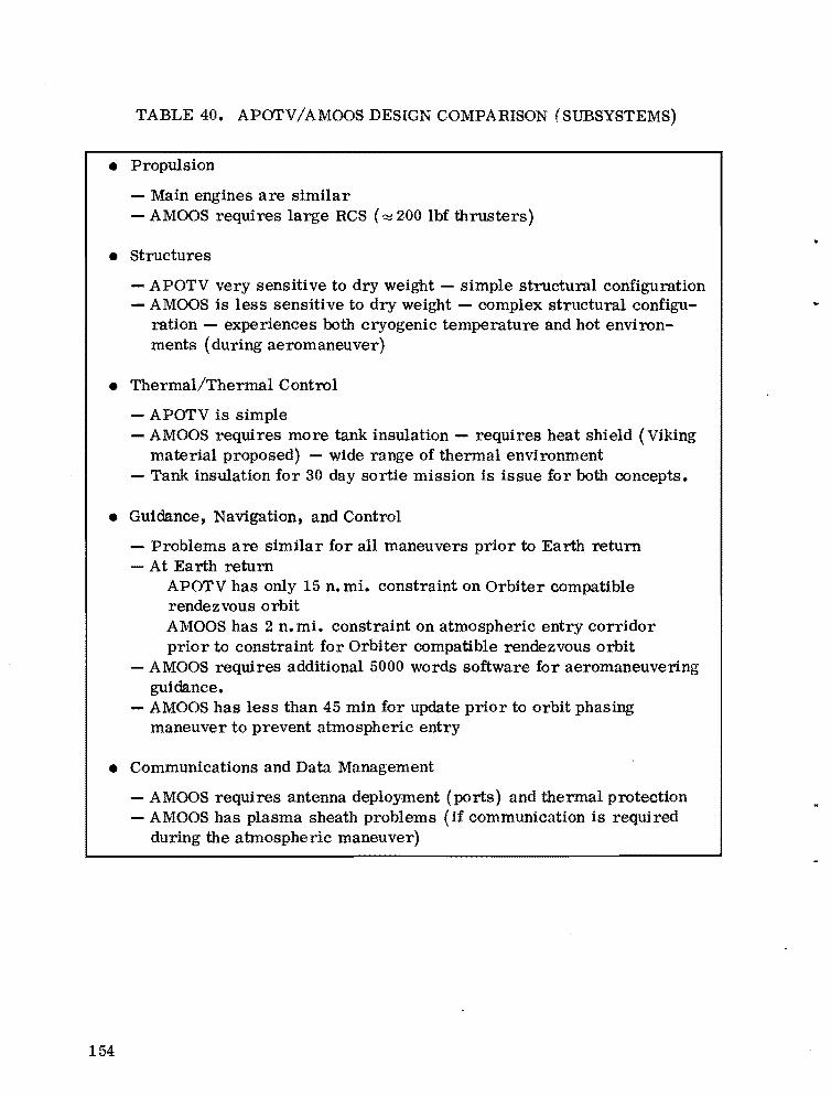
TABLE 40. APOTV/AMOOS DESIGN COMPARISON (SUBSYSTEMS)
• Propulsion
- Main engines are similar - AMaaS requires large RCS (~200 Ibf thrusters)
• Structures
- APOTV very sensitive to dry weight - simple structural configuration - AMaaS is less sensitive to dry weight - complex structural configu
ration - experiences both cryogenic temperature and hot environments (during aeromaneuver)
• Thermal/Thermal Control
- APOTV is simple - AMaaS requires more tank insulation - requires heat shield (Viking
material proposed) - wide range of thermal environment - Tank insulation for 30 day sortie mission is issue for both concepts.
• Guidance, Navigation, and Control
- Problems are similar for all maneuvers prior to Earth return - At Earth return
APOTV has only 15 n. mi. constraint on Orbiter compatible rendezvous orbit AMaaS has 2 n. mi. constraint on atmospheric entry corridor prior to constraint for Orbiter compatible rendezvous orbit
- AMaaS requires additional 5000 words software for aeromaneuvering guidance.
- AMaaS has less than 45 min for update prior to orbit phasing maneuver to prevent atmospheric entry
• Communications and Data Management
- AMOOS requires antenna deployment (ports) and thermal protection - AMaaS has plasma sheath problems (if communication is required
during the atmospheric maneuver)
154

The 100 000 lb Shuttle/AMOOS option appears to be the minimum single Shuttle launch system size which can meet the orbit transfer capability need. Limitations, capabilities, and cargo bay loading configurations for this case are summarized in Figure 27. This type data for the other options shown here and in the main body of the report are issues requiring further study.
O. Technology Requirements Technology development for the OTV has been underway for several years.
Some efforts have been specifically for the OTV while in some cases technology development in other programs is shared. A listing of the activities underway or completed by MSFC are shown in Table 38. Additional technology development needs are also shown in Table 38. It can be noted that these primarily address the problems associated with the AMOOS.
P. OTV Program Options Four OTV options have been identified; two of these options are for the
APOTV concept and two are for the AMOOS concept. For each concept, an option using the 65 000 lb Shuttle capability and the improved 100 000 lb Shuttle capability was identified. These options are described and summarized in Tables 41 through 44 with qualifications for each.
Following are the major issues relating to OTV:
1. Whether an OTV can be justified depends on the need for manned missions beyond low Earth orbit~
2. With a 65 000 Ib Shuttle capability, dual Shuttle launches will be needed to perform sortie missions. With the APOTV concept, the sortie mission will be limited to 14 days because of the payload capability of the dual stage sy~em. .
3. With a 100 000 lb Shuttle capability, the total number of launches is reduced by 28 to 35 percent for APOTV and AMOOS , respectively, when compared to the 65 000 lb Shuttle capability.
4. The AMOOS concept with, or leading to, a 100 000 lb Shuttle capability offers:
155
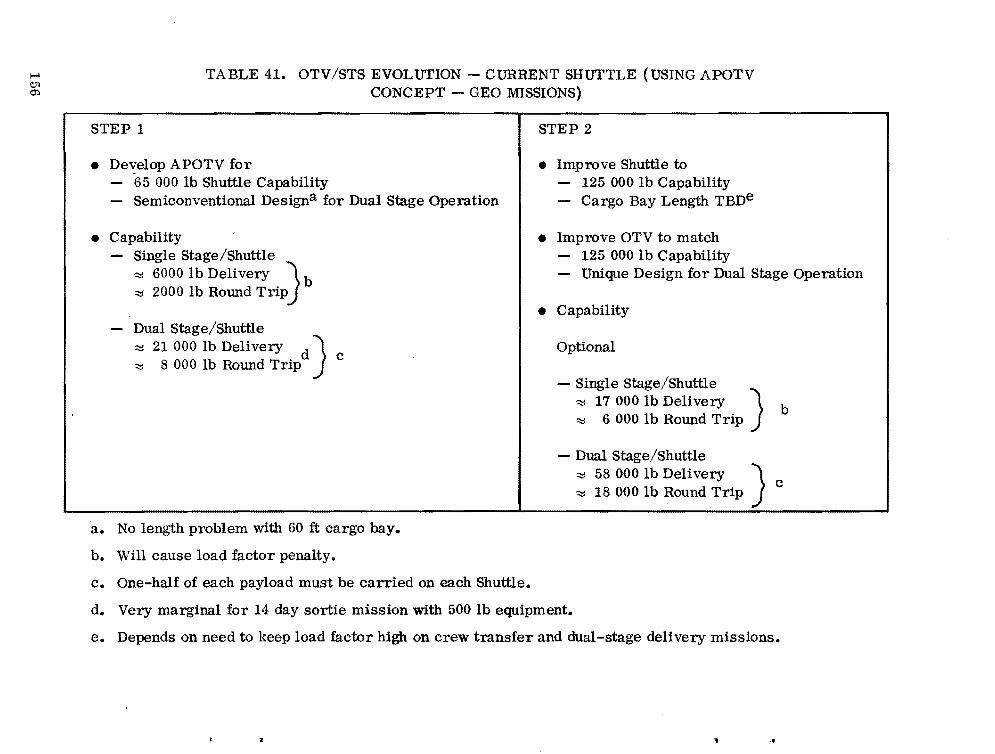
I-' TABLE 41. OTV/STS EVOLUTION - CURRENT SHUTTLE (USING APOTV ClI 0:. CONCEPT - GEO MISSIONS)
STEP 1
• Develop APOTV for 65 000 lb Shuttle Capability
- Semiconventional Designa for Dual Stage Operation
• Capability - Single Stage/Shuttle
'::::l 6000 lb Delivery \. b '::::l 2000 lb Round TripJ
- Dual Stage/Shuttle '::::l 21 000 lb Delivery d) '::::l 8 000 lb Round Trip c
STEP 2
• Improve Shuttle to 125 000 lb Capability
- Cargo Bay Length TBDe
• Improve OTV to match 125 000 lb Capability
- Unique Design for Dual Stage Operation
• Capability
Optional
- Single Stage/Shuttle ) '::::l 17 000 lb Delivery b '::::l 6000 lb Round Trip
- Dual Stage/Shuttle ~ 58 000 lb Delivery ) ~ 18 000 lb Round Trip c
a. No length problem with 60 ft cargo bay.
b. Will cause load factor penalty.
c. One-half of each payload must be carried on each Shuttle.
d. Very marginal for 14 day sortie mission with 500 lb equipment.
e. Depends on need to keep load factor high on crew transfer and dual-stage delivery missions •
..

TABLE 42. OTV/STS EVOLUTION - IMPROVED SHUTTLE (USING APOTV CONCEPT - GEO MISSIONS)
STEP 1 STEP 2
• Improve Shuttle to a
• Improve Shuttle to - 100 000 lb Capability - 125 000 lb Capability } d - 60 ft Cargo Bay - Cargo Bay Length TBD
• Develop APOTV to Match • Improve OTV to Match - 100 000 lb Shuttle Capability - 125 000 lb Shuttle Capability - Semiconventional/Unique Design for Dual-Stage - Unique Design for Dual-Stage Operation
Operation • Capability
• Capability - Single Stage/Shuttle - Single Stage/Shuttle ~ 17 000 lb Delivery } b
i::::I 2000 lb Delivery } b ~ 6 000 lb Round Trip ~ 4200 lb Round Trip
- Dual Stage/Shuttle - Dual Stage/Shuttle } ~ 58 000 Ib Delivery
~ 48 000 lb Delivery c ~ 18 000 lb Round Trip ~ 13 000 lb Round Trip
a. No length problem with 60 ft Cargo Bay.
b. Will cause Shuttle load factor penalty.
c. Marginal for 30-day, 4-man sortie mission.
d. TBD - Depends on need to keep load factor high on crew transfer and dual-stage delivery missions.
~
-:J 01

00
.... TABLE 43. OTV/STS EVOLUTION - CURRENT SHUTTLE (USING AMOOS CJl
CONCEPT - GEO MISSIONS)
STEP 1 STEP 2
• Develop AMOOS - For 65 000 lb Shuttle - Design Conventional, Unique, or in Between for
Single Stage Operation
• capabilitya - Single Stage/Shuttle
'::::I 13 000 lb Delivery ':!:::I 7 000 lb Round Trip
- Dual Stage/Shuttle '::::I 30 000 lb Delivery '::::I 16 000 lb Round Trip
• Improve Shuttle b
- 125 000 lb Capability - Cargo Bay Length (TBD)
• Improve OTV to Match - 125 000 lb Shuttle Capability - Unique (Short) Design for Single Stage
Operation
• Capability - Single Stage/Shuttle
'::::I 27 500 lb Delivery '::::I 17 000 lb Round Tripc
Optional - Dual Stage/Shuttle
'::::I 68 000 lb Delivery '::::I 37 000 lb Round Trip
a. No length problem, allowable payload length 24 to 32 ft, depending on type of design used for OTV.
b. Reduces transportation cost by approximately 50 percent.
c. Capability to transfer crew of 24.
'"

TABLE 44. OTV/STS EVOLtrrION - CURRENT SHtrrTLE LEADING TO IMPROVED SHUTTLE (USING AMOOS CONCEPT - GEO MISSIONS)
STEP 1 STEP lA
b
STEP 2
• Develop AMOOS • Improve Shuttle to • Improve Shuttle to - For 100 000 Ib Shuttle Capability - 100 000 lb Capability - 125 000 Ib Capability - Unique Design for Single stage - 60 ft Cargo Bay - Cargo Bay Length (TBD) } f
Operation • Develop A MOOS • Improve OTV to Match
• Fly Offloaded on 65 000 lb Shuttle - For 100 000 lb Shuttle Capability - Unique Design for Single Stage Operation
- 125 000 lb Shuttle Capability - Unique Design for Single Stage Operation
• Capabilitya - Single Stage/Shuttle • Capabilit/ • Capability
~ 11 000 lb Delivery - Single Stage/Shuttle - Single Stage/Shuttle ~ 5 500 lb Round Trip ~ 21 500 lb Delivery } d
~ 12750 lb Round Trip ~ 27 500 lb Delivery ~ 17 000 lb Round Trip } g
- Dual Stage/Shuttle -,,; 26 000 lb Delivery ~ 14 500 Ib Round Trip
Optional - Dual Stage/Shuttle
~ 52 000 lb Delivery
Optional - Dual Stage/Shuttle
:::I 68 000 lb Delivery "" 28 000 lb Round Trip } e ~ 37 000 Ib Round Trip
a. No problem; however, payloads limited to 24 ft on each Shuttle.
b. Reduces transportation by about 40 to 45 percent.
c. Payload limited to 24 ft length.
d. OK for up to 21-day, 4-man sortie mission.
e. Length problem with some payloads.
f. Should reduce transportation cost.
g. Capability to transfer crew of 24.
I-'
c:o 01

- Single Shuttle launch of large elements and the man sorlie missions
- Lowest cost for transportation
- Programmatic flexibility as to the time of introducing the improved Shuttle capability.
The selection of an OTV concept or the option to be used is not needed at this time. OTV planning and schedule considerations indicate that decisions on concept and option selection are needed in late FY-79. Other concepts or options may be identified in the meantime.
Q. OTV Activity Status/Future The OTV activity status and near term future needs are summarized in
Table 45. The future activity should primarily lead to better technical and programmatic definition of OTV and to acquire technology readiness in a timely manner.
XVII. RECOMMENDATIONS
Recommendations for future OTV efforls are as follows:
1. Key future system work to:
Current Shuttle capability leading to improved Shuttle (95 000 to 100 000 lb)
Sorlie mission manned elements
Minimum length configurations.
2. Key OTV engine development to:
Shorl length concepts
Variable/high oxidizer-to-fuel mixture ratios
3. Key technology development efforts as identified.
..
160
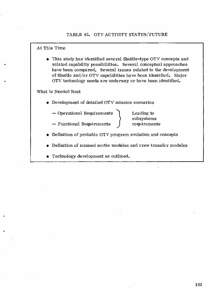
TABLE 45. OTV ACTIVITY STATUS/FUTURE
At This Time
• This study has identified several Shuttle-type OTV concepts and related capability possibilities. Several conceptual approaches have been compared. Several issues related to the development of Shuttle and/or OTV capabilities have been identified. Major OTV technology needs are underway or have been identified.
What is Needed Next
• Development of detailed OTV mission scenarios
- Operational ReqUirements} Leading to sUbsystems
- Functional Requirements requirements
• Definition of probable OTV program evolution and concepts
• Definition of manned sortie modules and crew transfer modules
• Technology development as outlined.
161


APPENDIX A
A SUMMARY OF THE DEVELOPMENT STATUS OF CHEMI CAL ENGINE SYSTEMS UNDER CONSIDERATION FOR THE
ORBITAL TRANSFER SYSTEM (OTS) (NOVEMBER 1976)
163

Development status of Chemical Engine Systems Under Consideration for the Orbital Transfer System (OTS)
Estimated Timet Engine System Of A vailabil1ty
1. RL10A3-3 Present '!'
2. RL10 Category lIB 1985
3. RL10 Category IV 1985
4. Advanced Space Engine 1985
5. Orbit Maneuvering Engine 1985
6. Solid Rocket Motor 1985
7. Storable Propellant High Pressure Engines 1985
8. Space Shuttle Main Engine 1980
9. Plug Cluster Concept 1985
10. Aerospike Engine Concept 1985
1. RL10A3-3
The 15 000 lb thrust RL10A3-3 lox/hydrogen engine is the current production engine for the Centaur upper stage which is being flown on Atlas and Titan TIl launch vehicles. The present production run is for 14 engines and will terminate in February 1977. A proposal by the contractor, Pratt & Whitney, has recently been submitted to NASA- LeRC for an additional six engine production run (with an option for four more engines) for NASA-committed Centaur launches through 1980. The last of these engines will be delivered around August 1978 for integration into the stage. The Pratt & Whitney program technical manager foresees a possible additional small production run to accommodate the phase-in Shuttle transition period. Thus, the best projection for RL10 availability is late 1978 or possibly through 1980, depending on the NASA launch schedule utilizing expendable vehicles. The RL10A3-3 has an excellent reliability record and is the best performing engine currently operational; however, its technology base is approximately 1958 state-of-the-art. I is 444 sec at a nozzle expansion
sp ratio of 57:1. Engine mixture ratio is 5:1, and the engine utilizes an expander cycle turbopump power drive.
1. Assuming FY-79 Funding
164

2. RLI0 Category lIB
The 15 000 lb thrust RLI0 Category lIB is the baseline engine assumed for the MSFC Baseline Space Tug (1974) and is well characterized as the result of a Pratt & Whitney MSFC funded study conducted in 1973. (Technology level is mid-1960's.) This improved engine is derived from the current operational engine and can be made available with present technology and no advances in the state-of-the-art. To increase the I from 444 to 456.4 sec, the injector has
sp been reoptimized to operate at a 6: 1 propellant mixture ratio and the nozzle expansion ratio increased to 205:1. The engine is configured with a two-poSition nozzle with the primary section recontoured for better performance. Further increases in I can be achieved by increasing the nozzle expansion ratio beyondsp 205:1 to a practical maximum of 262: 1 (I = 459 sec). The chamber pressure
sp is 400 psia (same as the current production model), and the engine operates in the same expander cycle.
3. RLI0 Category IV
The 15 000 Ib thrust RLI0 Category IV engine represents the best performance available from the expander power cycle. It is a new engine design but does not require significant advance in technology and, therefore, is considered current state-of-the-art. Chamber pressure is increased to 915 psia, and nozzle expansion ratio on the order of 400:1 is achievable. At the maXimum expansion ratio, I is 470 sec at a propellant mixture ratio of 6:1. This engine
sp is also defined in the 1973 Pratt & Whitney report, but is not as well characterized as the Category II engine.
4. Advanced Space Engine
The 20 000 Ib thrust ASE is a staged-combustion cycle engine operating at chamber pressures on the order of 2000 psia. These characteristics result in a high performance engine with some weight and envelope advantages. I '
sp is nominally 470 sec for operation at a 6:1 mixture ratio. Major components and subsystems have been designed and developed by Rocketdyne under NASA-LeRC contracts since the early 1970's. This engine is well characterized and was selected for the main engine system of the Space Tug defined by the Preliminary Design Office in 1972. (Engine thrust was set at 10 000 Ibf.) Hardware items fabricated to date include the igniter, preburner, high pressure oxygen and hydrogen turbopumps, combustion section, and upper nozzle section. Combustor firing tests have been made in addition to laboratory testing of the other hardware
165

items and a combined preburner and regeneratively cooled thrust chamber assembly test is scheduled for this month. Although this engine would be considered a new development item, the technology level is early to mid-1970's. If continued, the present modest level of NASA -LeRC funding should eventually lead to hardware development appropri~te for all-up engine demonstration testing around 1980.
5. Orbital Maneuvering Engine
A candidate Earth-storable propellant engine system for the OTS is one derived from the Shuttle 6000 lb thrust Orbit Maneuvering Engine (OME). The fundamental design considerations for long service life, multiple starts, and reusability are fully compatible with OTV requirements. Significant modifications would be required for OTV application; however, these would not represent advances in the state-of-the-art. The most prominent of these modifications would be to change from pressure-fed to pump-fed operation and to increase the engine thrust to a more desirable level. The propellant mixture ratio (N20 4/
MMH) woul d be increased from 1. 65: 1 to 2: 1 for improved performance and the nozzle expansion ratio increased from 55:1 for the same reason. These changes would constitute a new engine based on existing technology. The various options for OME derivative engines were explored by the Aerojet Liquid Rocket Company under MSFC-funded studies and documented in 1974 in support of the Storable Space Tug Study. The I range is 330 to 335 sec, depending on the cycle,
sp chamber pressure, expansion ratio, propellant mixture, etc.
6. Solid Rocket Motor
Solid propellant motor manufacturers profess to have developed highly sophisticated computer programs that can predict with a high degree of accuracy in a relatively short time the motor design needed when given a set of requirements. This is exemplified in the IUS program which is using state-of-the-art components and scheduled to be operational by 1980. The case proposed is filament wound with Kevlar, a high-strength low-density fiber, that will maximize stage mass fraction. Over 200 cases have been made for the Trident and MX (advanced Minuteman) programs, and the industry at large has confidence in its ability to work with this relatively new material.
Carbon-carbon nozzles are being touted as the nozzle material to use for space application because with several limited duration firings no visible signs of erosion have been noticed. In the IUS program, carbon-carbon and a more conventional ablative type backup nozzle are to be made and tested. After these tests, a comparison will be made'to determine which of the two materials will be
166
used in the IUS motors. It is expected that the carbon-carbon nozzle will give better performance by 2 to 3 sec, resulting in a higher delivered I • Although the nozzle is gimbaled, this is not a new technology item. sp
Minimum development time for a new state-of-the-art motor is on the order of 2.5 years depending on the long lead-time items, the amount of trade studies imposed, and the number of test/qualification motors required of the program.
The maximum vacuum I expected in the foreseeable future is approxisp
mately 300 sec for Class 2 propellants.
7. Storable Propellant High Pressure Engines
Parametric and design analysis of several high pressure storable propellant engine concepts in the 6000 to 20 000 lb thrust range were studied by Aerojet Liquid Rocket Company, under contract from MSFC, in 1973. Gas genel11tor and staged-combustion cycle engines were investigated, with all engines using nitrogen tetroxide (N20 4) as the oxidizer and monomethyl hydrazine (MMH) as the fuel. Both types of engines were regeneratively and film cooled with MMH. Maximum chamber pressure is on the order of 1000 psia.
The gas generator cycle engines are equipped with turbopump assemblies driven by exhaust products from N20 4/MMH gas generators. The turbine exhaust gases are then ducted into the main nozzle downstream of the throat or into small auxiliary nozzles. The staged-combustion engines are equipped with turbopump assemblies driven by hot gases produced in N204/MMH prebumers. These exhaust gases are then fed directly into the main combustion chamber.
These storable-propellant high-pressure engines produce I rangingsp
from 335 to 349 sec, depending upon engine thrust, nozzle expansion ratio, chamber pressure, percent fuel used for film cooling (i. e., allowable chamber wall temperature), and overall engine propellant mixture ratio.
8. Space Shuttle Main Engine
The 470 000 lb thrust Space Shuttle Main Engine (SSME) is a staged combustion cycle engine operating at chamber pressures on the order of 3000 psia. The high thrust of the engine precludes its use for earlier (and smaller) elements of the OTS. However, there is a potential application for later (and larger) OTV's. Nominal vacuum I is 455 sec. The SSME will be operational in 1979,
sp
167

barring serious difficulties in qualification testing. Technology level is considered to be early to mid-1970's. The engine as configured for the Shuttle has no extendable/retractable nozzle, but is throttable over a range of 50 to 109 percent of the rated thrust level.
9. Plug Cluster Concept
A potentially attractive alternative to using conventional bell nozzle engines is the grouping of multiple small engines in a "plug cluster" geometry. For OTS application, we have selected a lox/hydrogen engine of 1500 lb thrust arranged in a circular fashion around an aerodynamically designed central nozzle section to reduce overall stage length. The individual nozzle expansion ratio is 40:1; however, when appropriately arranged in the plug cluster geometry, the collective expansion ratio is 400:1 resulting in an effective I of 466 sec. The
sp number of individual engine modules may be varied to adjust the total thrust as desired. The nominal propellant mixture ratio is approximately 6: 1. The operation of the plug cluster is necessarily sensitive to geometrical arrangement. For performance and stage conceptual layout purposes, the geometric relationships as they are presently theorized have been defined. The radius which defines the circle circumscribing the cluster of individual engines is determined by selecting the desired performance level (effective expansion ratio) and the desired total thrust (number of engine modules) and by specifying the throat diameter of the individual engine. From this, the geometry of the central nozzle section is determined. The individual nozzles are canted slightly inward to direct the exhaust product flow along the central nozzle cone surface.
The plug cluster is also an attractive concept for booster stages. By clustering engines such as the SSME or Space Shuttle Booster Engine (SSBE) around a central plug, altitude compensation is achieved which increases the average I (over a boost trajectory) approximately 6 percent when compared
sp to bell nozzle engines not used in a plug cluster arrangement. The plug cluster concept also has a potential for propulsion system/stage structure integration which could result in a decrease in stage inert weight. HLLV boosters (Class IV) using the plug cluster concept have been conceptually designed in-house.
The plug cluster design is presently undergoing conceptual evaluation by Aerojet (System Design) and Rocketdyne (Cold Flow Testing) and, therefore, must be considered only as theoretically attractive at this time, pending feasibility analyses and the usual demonstration testing. Funding is through NASA- LeRC.
168

10. Aerospike Engine Concept (OTS - 1985)
The current proposed baseline Aerospike engine for upper stages would operate on lox/hydrogen propellants in an expander cycle at a chamber pressure of 1000 psia, producing a thrust of 25 000 lb and a vacuum I of 470 sec at an
sp expansion ratio of 200:1 and a mixture ratio of 5;1. From analytical studies, it appears that the Aerospike engine is weight competitive with bell nozzle engines; however, a complete flight weight engine (i.e., turbopumps, valves, chamber, and nozzle) has not been built and successfully tested at this time. The major advantage of the Aerospike engine is the potential to achieve high performance in a shorter length than achievable with a bell nozzle engine of the same thrust. The shorter engine length would therefore result in a shorter overall stage length. Rocketdyne has been investigating the toroidal chamber Aerospike engine, applicable to upper stages, since the early 1970's. The present effort is a successor program to an earlier AFRPL fiuorine/hydrogen demonstration program that terminated with destruction of the test article and facilities during an attempted demonstration hot firing. A demonstration lox/hydrogen 25 000 lbf thrust, chamber/nozzle was initially built and tested by Rocketdyne under contract from AFRPL. This test program was discontinued by AFRPL in 1975 because of an oxygen cooling leak during a test firing which resulted in major damage to the Aerospike chamber and nozzle. In January 1976, NASA/LeRC took over the Aerospike program by initiating a contract with Rocketdyne to repair this test article (chamber and nozzle) and to test fire it again. After attempting unsuccessfully to repair the test article, NASA/LeRC has decided to discontinue the effort because new hardware could be required which is out of the scope and funding level of the contract. It appears unlikely that funding will be available to continue this program in the foreseeable future.
169


APPENDIX B
SUPPORTING STUDY DATA NOT COVERED BY THE NARRATIVE
171
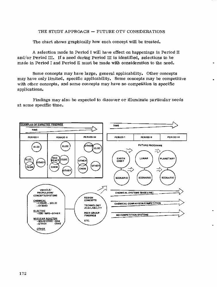
____
THE STUDY APPROACH - FUTURE OTV CONSIDERATIONS
The chart shows graphically how each concept will be treated.
A selection made in Period I will have effect on happenings in Period II and/or Period III. If a need during Period III is identified, selections to be made in Period I and Period II must be made with consideration to the need.
Some concepts may have large, general applicability. Other concepts may have only limited, specific applicability. Some concepts may be competitive with other concepts, and some concepts may have no competition in specific applications.
Findings may also be expected to discover or illuminate particular needs at some specific time.
•
EXAMPLES OF EXPECTED FINDINGS
TIME i> PERIOD I PERIOD II PERIOD III
ELEC8 8 ~ THER
CHEM~e 8
DESIGN CHEMICAL CONCEPTS
-LiaUiD - SOLID -HYBRID
elECTRIC ION MPD-oTHER
NUCLEAR REACTOR SOLID CORE GAS
-OTHER CORE
OTHER
--==------{>TIME
PERIOD I PERIOD II PERIOD III
FUTURE PROGRAMS
---C-H-EM-tC-A-L-S-Y-Sn--MS~.B-AS~E~L-'N~E~)----------~V>
~C~H~E~M~tC~A~LC~O:MP:':AR~I~SO~N~~~OM~PE~T~tTl~ON~________~
V ~
NO COMPETITION SYSTEMS
172

SERVICE VEHICLES DERIVED FROM MAN/CARGO VEHICLES
Shown are service vehicles which can be derived from man/cargo vehicles used with the AMOOS.
To accommodate extravehicular activity, a second compartment is included. The second compartment serves as an airlock and cargo for the service vehicle.
A solar array and the necessary power conditioning equipment are added to extend the service vehicles! independent operating time.
It may be necessary to add radiation shielding around the cabin/control compartment to reduce radiation exposure by the crew.
MAN/CARGO VEHICLE SERVICE VEHICLE
I... 22'
/' - --,
t,,-\ ;' !jj;~':\ / / I ~ ; \ I I,-,1\/ 1:/11 1-;"; ~.... _-=_;;:J/...
38.5' -I I 31' 33'
1 ,
I
Ii d" I.
" '\ ~ \.......
-------~ ,l._,.,;'i;>_
1 1 '_-_" ,/~r- -- -- ----"
,~<:>; - ~;!J" '\ /'\ , - J'5i!f.J f, i \I .... --,~ .'~l/ ,..:/ }
" .. _ ~, \, l' £.:.'.-:j, .:.....J / .... - - - - - - -- ---
, 26' -28' -I
-I
173

AMOOS FOR HLLV
The configuration shown reflects a possible final stage of an HLLV based on the aeromaneuvering concept for reentry deceleration. The configuration was sized for 375 000 lb of lox/hydrogen at a mixture ratio of 6:1. The diameter selected was arbitrary except for giving a reasonable length to diameter ratio. The reentry thermal protection system would require return through the atmosphere for eventual recovery. The payload compartment is assumed to be an integral part of the configuration so as to make the payload carrier reusable.
L02 I LH2 AMOOS, HLLV CLASS, GROUND RETURN
174
......-------80'--------~·1 /--........... ,. - - - ........
,{ \ / '\ (,--(( \,' \ I _~\ 1\ L" I \ I
_/ ,--- ./'
375,000 LBS PROPELLANT 6:1 MIXTURE RATIO HI PC ENGINE, F 76,000 LBS, € =400:1
PAYLOAD
HLLVBOOST INTERFACE
..
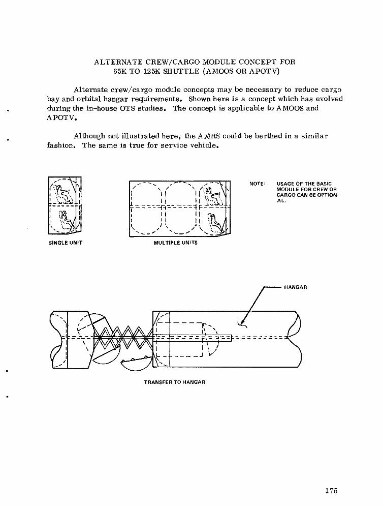
ALTERNATE CREW/CARGO MODULE CONCEPT FOR 65K TO 125K SHUTTLE (AMOOS OR APOTV)
Alternate crew/cargo module concepts may be necessary to reduce cargo bay and orbital hangar requirements. Shown here is a concept which has evolved during the in-house OTS studies. The concept is applicable to AMOOS and APOTV.
.. Although not illustrated here, the AMRS could be berthed in a similar fashion. The same is true for service vehicle.
NOTE: USAGE OF THE BASIC MODULE FOR CREW OR CARGO CAN BE OPTION· Al.
SINGLE UNIT MULTIPLE UNITS
TRANSFER TO HANGAR
175

c
AMOOS A~D APOTV STAGE LENGTH VERSUS PROPELLA~T
LOADI~G (15 ft CARGO BAY DIAMETER)
The graph reflects studies of sizing both the AMOOS and APOTV for compatibility with a 15 ft diameter cargo bay using two lox/hydrogen mixture ratios. The lengths shown are total including retracted nozzles on the Hi P engines. A constant thrust to weight of 0.15 was used in engine sizing.
The APOTV slope is essentially straight because tank diameter is fixed, and length is primarily associated with the propellant capacity. In sizing the AMOOS stages, a nonlinear curve results as a result of the approach used in tank sizing. The larger configurations result in decreased tank diameters which, in turn, increase tank length.
APOTV 10
~r-____.-____~AM~OO~S'-____-r__~
60
j::: !!: :r ~ 50 (!) z w .... w (!) ~ < 40 ~ ~
ot't.'\~ ~II)
~ ~ 30~~----+-----+---~r-----r---~ :::::--2020 !-!---=--r-~-----;!;;----;:;I;:----=,
50 60 70 80 90 100 50 60 10 80 90 100
PROPELLANT 11000 LSI PROPELLANT (1000 LsI
NOTE:O/F REFERS TOTHE OXIDIZER/FUEL AVERAGE MIXTURE RATIO USED SY THE ENGINE
176
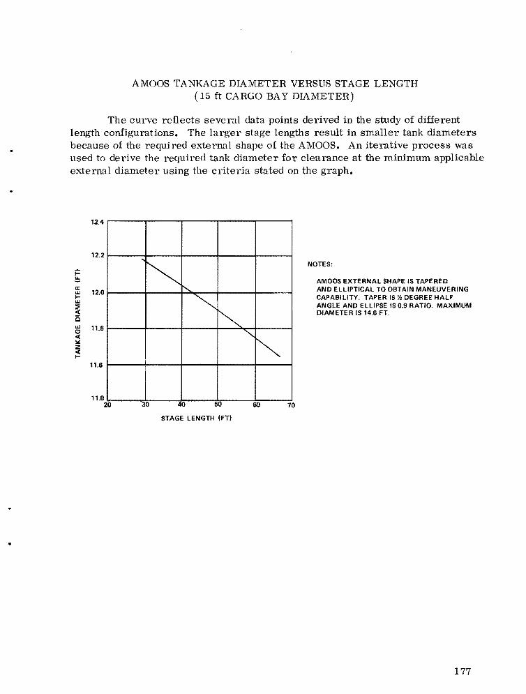
AMOOS TANKAGE DIAMETER VERSUS STAGE LENGTH (15 ft CARGO BA Y DIAMETER)
The curve reflects several data points derived in the study of different length configurations. The larger stage lengths result in smaller tank diameters because of the required external shape of the AMOOS. An iterative process was used to derive the required tank diameter for clearance at the minimum applicable external diameter using the criteria stated on the graph.
12.4
12.2
'~ ........
~ ~
30 40 50
STAGE LENGTH ~FTI
"" ~
NOTES: j:: ~ AMOOS EXTERNAL SHAPE IS TAPERED a: AND ELLIPTICAL TO OBTAIN MANEUVERINGw 12.0 I CAPABILITY. TAPER IS Y, DEGREE HALF w
ANGLE AND ELLIPSE IS 0.9 RATIO. MAXIMUM:F « DIAMETER IS 14.6 FT. 15 w 11.8CI « ~ z « I
11.6
11.0 20 60 70
•
177

---
PA YLOAD WEIGHT VERSUS LOW EARTH ORBIT WEIGHT REQUIRED AND STAGE LENGTH (15 ft DIAMETER CARGO BAY)
The charts show subject data for AMOOS and APOTV systems for single and dual stage applications.
For single stage applications the data show:
For Delivery Only APOTV weight requirements are higher, and stage lengths are approximately equal to AMOOS for equal payloads
For Round Trip AMOOS is much more favorable in weight and length for equal payloads
For dual stage application, the data show the same trend as for single applications with the differences somewhat lower.
o w a: ~ 150 w a: .... % CI
; 100 .... iii a: o % 50Ii: « w
~ o
DELIVERY PAYLOADS ISYN ORSI
WEI HT-Vv ?(:~
GTH~ ?
i... §
100 :: 200 o w a:
_5 .... a
75 ::l ~ 150 !!:: .... % :J: .... (:J
:i(:J -
~ 50 ....... 100
w iii CI a: « 0
In ~ 25 ~ 50
w
~ ... o 0
ROUND TRIP PAYLOADS (SYN ORBI
LI100
j::: IIILEN TH...... III75 !!::V %
I; Z III/ ~ ...50
"-WEI CIHT :: w
/'t? ... 25
o o 10 20 30 40 50 o 5 10 15 20 25
DELIVERY PAYLOAD (1000 LBI ROUND TRIP PAYLOAD 11000 LSI
Single Stage (One Shuttle Launch) AMOOS
178
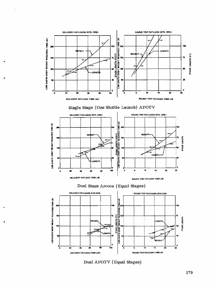
;;j -'
~ 200 Q IIIa:
8 160III
a: .... e iii II: 100 .... iiia: 0
~ 60a: « III
~ 0
iii oJ
~ Q.. 0:
§.. 0: ... ~ I I 0: 0
; c.. ~
iii oJ
~ Q.... 5 51.. !i:
• S!•.... i!! !§
~ c.. ~
DELIVERY PAYLOADS (SYN. ORB,) ROUND TRIP PAYLOAD ISYN. OR8.1
0
L...____'-__--:'-:-__-'____....L....__---IO
10 :1.0 30 40 60
oL-____~__L____L_____L___~ o 2So 5 10 15
2110
1150
100
60
0
0
2110
1150
100
150
0 o
DELivERY PAYLOAD 11000 LB.I ROUND TRIP PAYLOAD 11000 LBl
Single Stage (One Shuttle Launch) APOTV
DEUVERY PAYLOADS ISYN. OR8J ROUND TRIP PAYLOADS ISYN. ORal
0 o~____~____~_____L____-L_____JO
• 40 110 80 100 o w ~ :1.0 m
DELIVERY PAYLOAD (1000 L81 ROUND TRIP PAYLOAD (1000 LB)
Dual Stage Amoos (Equal Stages)
DELIVERY PAYLOADS ISYN ORBI ROUND TRIP PAYLOADs ISYN ORB)
1 100
7 1
WEIGH" LENGTH, ii'..~ l....2::
100 i"-.
V 50 IU
~ ~ ~ p- LENGTH --
~ ;7
6
~'wEIGHTI
20 eo 0 100 o 10 15 20
DELIVERY PAYLOAD (1000 Las) ROUND TRIP PAYLOAD (1000 LB)
Dual APOTV (Equal Stages)
25
o 25
179

OTV CONCEPT COMPARISON AMOOS VERSUS APOTV GEOSYNCHRONOUS ORBIT CAPABILITY
Geosynchronous orbit payload capability was developed for the AMOOS and APOTV systems as a function of Shuttle low Earth orbit capability of 65 000 to 125000 lb. Payload delivery and payload round trip capability were derived for one, two, and three Shuttle launches. Two OTV's were employed on the second and third Shuttle launches. The payload delivery associated with an APOTV and a 65 000 lb Shuttle is approximately 8000 lb, and delivery associated with a 125 000 lb Shuttle is approximately 22 000 lb. Payload round trip capability associated with an APOTV and a 65 000 lb Shuttle is approximately 2800 lb, and round trip payload associated with a 125 000 lb Shuttle is approximately 8500 lb. Achieving the 10 000 to 20 000 lb round trip payload requires two Shuttle launches with two OTV stages having a Shuttle growth capability of 80 000 to 125 000 lb. Two Shuttle launches are also required to achieve the 50 000 to 70 000 Ib payload delivery.
ONE SHUTTLE LAUNCH
ROUNDTRIP
30
~ ~ ~- f..-~-
20
10
o 60 80 100 120
DELIVERY ONLY
1. AMOOS CAPABILITY 2. ALL PROPULSIVE
CAPABILITY
180
TWO SHUTTLE LAUNCH
+ +ROUNDTRIP
THREE SHUTTLE LAUNCH
~ +ROUNDTRIP
30 60r---r---+---~--~
20
10
0 60 80 100 120
--------------------7-------------------DELIVERY ONLY
DELIVERY ONLY
120
A , .,..
10~ ",....",
I.........
80
40
o 80 0100 120 60 80 100 120L_______________________________________ _
SHUTTLE CAPABILITY (K-POUNDS)
...

•
STAGING EFFECTS - OTV HIGH PERFORMANCE/LIQUID SYSTEMS
Analysis was conducted to determine the staging sensitivity on the APOTV and AMOOS system for geosynchronous payload delivery and payload round trip missions. Staging concepts of single stage, dual stage, and drop tank plus stage were considered. A 50 percent gain in payload capability can be realized by employing the drop tanks plus stage as compared to a single stage configuration APOTV system. However, the drop tanks are expended, and the on-orbit operation is more complex with the drop tanks; these points must be factored in to determine the real cost effectiveness of drop tank plus stage as compared to a single stage.
.. '" "iii ~
~ 9 ~ ... !!! 0 z 0a:
'" u z >S.. "
ALL PROPULSIVE STAGE ~r---~~~__~__~~-1~3,~-r-----'
-----
18\-----+-----+------+------l
12' 12 ---r-- ---1---
'- - r- - __ ~ --- ROUNDTRI --
8 - DELIVERY
13'
12'
(1'
~r_----._--~AM~OO~S----r-----,
16~----+-----+------r----~
12~----+-----~-----+----~ --- ROUNDTRIF
- DELIVERY
--~ -><, --_==-=-:.r- __ Ul. ---- -(3'-------
11'
o~----~----~----~----~°M·L-----.~----~I00------I~~----~140 • • 100 140
LOW EARTH ORBIT START WEIGHT 11000 LB: INCLUDES PAYLOAD'
(1) DROP TANKS PLUS STAGE 12' DUAL STAGES 13' SINGLE STAGE
(1) SINGLE STAGE 12' DUAL STAGE
LOW EARTH ORBIT START WEIGHT 11000 LB; INCLUDES PAYLOAD'
13' DROP TANK PLUS STAGE
40
:M
18
8
80
ALL PROPULSIVE STAGE
____ ROUNDTRIP
__ DELIVERY
---- 3 .... - .,-.-....,:=-----..,.-""- --.... ---- .... _- , --:::--.... -------• 100 140
AMOOS 40
____ ROUND TRIP
fa 32· _____ DELIVERY ....
:M
16
M 80 100
SHUTTLE CAPABILITY 11000' LBS.
140
181
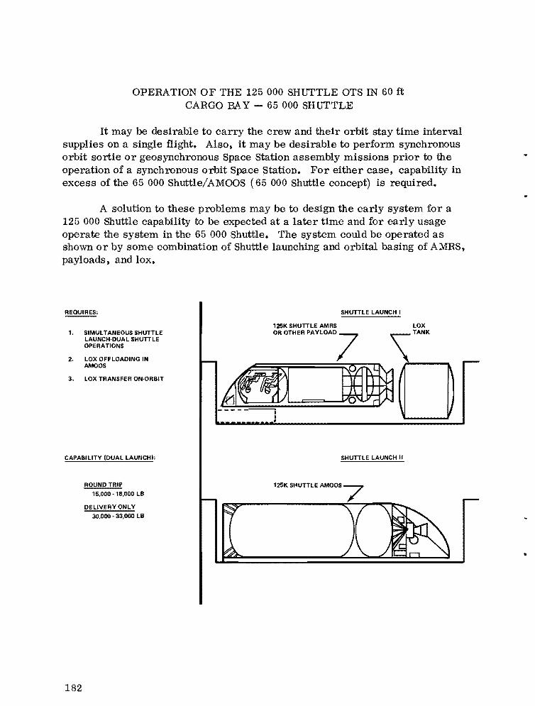
OPERATION OF THE 125000 SHlITTLE OTS IN 60 ft CARGO BAY - 65 000 SHlITTLE
It may be desirable to carry the crew and their orbit stay time interval supplies on a single flight. Also, it may be desirable to perform synchronous orbit sortie or geosynchronous Space Station assembly missions prior to the operation of a synchronous orbit Space Station. For either case, capability in excess of the 65 000 Shuttle/AMOOS (65 000 Shuttle concept) is required.
A solution to these problems may be to design the early system for a 125 000 Shuttle capability to be expected at a later time and for early usage operate the system in the 65 000 Shuttle. The system could be operated as shown or by some combination of Shuttle launching and orbital basing of AMRS, payloads, and lox.
REQUIRES:
1. SIMULTANEOUS SHUTTLE LAUNCH·DUAL SHUTTLE OPERATIONS
2. LOX OFF LOADING IN AMOOS
3. LOX TRANSFER ON'ORBIT
CAPABILITY IDUAL LAUNCH):
ROUNDTRIP
15,000 18,000 LB
DELIVERY ONLY
30,000 33,000 LB
SHUTTLE LAUNCH I
125K SHUTTLE AMRS LOX
0,0'"" ,mOAD7 \'"""
-~ aD•
SHUTTLE LAUNCH II
182
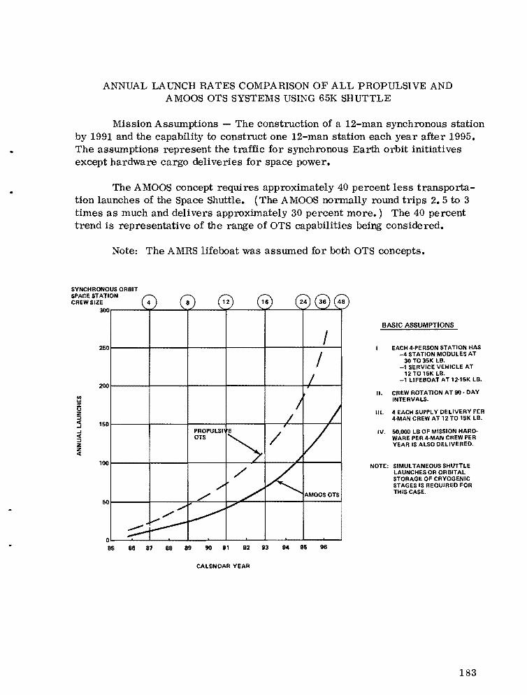
ANNUAL LAUNCH RATES COMPARISON OF ALL PROPULSIVE AND AMOOS OTS SYSTEMS USING 65K SHUTTLE
Mission Assumptions - The construction of a 12-man synchronous station by 1991 and the capability to construct one 12-man station each year after 1995. The assumptions represent the traffic for synchronous Earth orbit initiatives except hardware cargo deliveries for space power.
The AMOOS concept requires approximately 40 percent less transportation launches of the Space Shuttle. (The AMOOS normally round trips 2. 5 to 3 times as much and delivers approximately 30 percent more.) The 40 percent trend is representative of the range of OTS capabilities being considered.
Note: The AMRS lifeboat was assumed for both OTS concepts.
SYNCHRONOUS ORBIT SPACE STATION CREW SIZE
~O~----~~--~~----~~--~~----~~~~~
I 250~-----+------+------+------4-----~~~--~
/ 200
'"...:x: (.) z :::I C 1SO..I ..I C :::I Z Z C
100
50~-----+------~~--~~~--4r----~r-----~
o~~~-L--~--~__~~__~__~__~~~____~
BASIC ASSUMPTIONS
EACH 4-PERSON STATION HAS -4 STATION MODULES AT
30 T035K LB. -1 SERVICE VEHICLE AT
12 TO 15K LB. -1 LIFEBOAT AT 12-15K LB.
II. CREW ROTATION AT 90· DAY INTERVALS •
III. 4 EACH SUPPL Y DELIVERY PE:R 4-MAN CREW AT 12 TO 15K LB.
IV. SO,OOO LB OF MISSION HARDWARE PER 4·MAN CREW PER YEAR IS ALSO DELIVERED.
NOTE:: SIMULTANEOUS SHUTTLE LAUNCHES OR ORBITAL STORAGE OF CRYOGENIC STAGES IS REOUIRED FOR THIS CASE.
85 86 87 88 89 90 81 82 83 94 85 86
CALENDAR YEAR
183

ANNUAL LAUNCH RATES FOR AMOOS WITH 125K SHL'TTLE
Mission Assumptions - The construction of a 12-man synchronous station by 1991 and the capability to construct one 12-man station each year after 1995. The assumptions represent the traffic for synchronous Earth orbit initiatives except hardware cargo deliveries for space power.
A .J:-man crew module with the crew supplies is used up to the time the HLLV is introduced. After HLLV introduction, the crew module is converted to a 12-man system and the crew supplies and all other cargo carried on the HLLV.
SYNCHRONOUS ORBIT SPACE STATION CREW SIZE
en w
50r-----_+------~------~------+_------~~--~
~r-----_+------~------~------+_------~----~
~~r-----_+------~------~------+_~~--~----~z ~ ..J ..J c( :;j
z 20 r-----_+------~------~--_r_--+_------~----~:t
10r-----_+-------b~----~------+_------~----~
CALENDAR YEAR
184
BASIC ASSUMPTIONS
I. EACH 4 - PERSON STATION HAS
II.
- 4 STATION MODULES AT 30 TO 35K LB.
- 1 SERVICE VEHICLE AT 12 TO 15K LB.
- 1 LIFEBOAT AT 12-15 K LB.
CREW ROTATION AT 90 - DAY INTERVALS.
III. 4 EACH SUPPLY DELIVERY PER 4-MAN CREW AT 12 TO 15K LB.
IV. 50,000 LB OF MISSION HARDWARE PER 4 - MAN CREW PER YEAR IS ALSO DELIVERED.
NOTE: NO SIMULTANEOUS SHUTTLE LAUNCHES OR ORBITAL ASSEM· BLY IS REQUIRED. CARGO BAY LENGTH ABOUT 95 - 105 FT NEEDED.

..
•
ANNUAL LAUNCH RATES FOR AMOOS WITH 125K SHUTTLE AND HLLV AFTER 1991
Mission Assumptions - The construction of a 12-man synchronous station by 1991 and the capability to construct one 12-man station each year after 1995. The assumptions represent the traffic for synchronous Earth orbit initiatives except hardware cargo deliveries for space power.
A 4-man crew module with the crew supplies is used up to the time the HLLV is introduced. After HLLV introduction, the crew module is converted to a 12-man system and the crew supplies and all other cargo carried on the HLLV.
SYNCHRONOUS ORBIT SPACE STATION CREW SIZE
50
40
'" w:c Q Z ::I
:5 30 ... 0( ::I Z
i 20
65K SHUTTLE ONLY (REFERENCE)
/ /
CALENDAR YEAR
BASIC ASSUMPTIONS
I. EACH 4· PERSON STATION HAS - 4 STATION MODULES AT
30 T035K LB. - 1 SERVICE VEHICLE AT
12T015K LB. - 1 LIFEBOAT AT 12·15K LB.
II CREW ROTATION AT 90· DAY INTERVALS.
Ill. 4 EACH SUPPLY DELIVERY PER 4 MAN CREW AT 12 TO 15K LB.
IV 50,000 LB OF MISSION HARD· WARE PER 4-MAN CREW PER YEAR IS ALSO DELIVERED.
V. 4· MAN CREW MODULE UP TO 91· 12· MAN CREW MODULE THERE· AFTER.
IV. 125K SHUTTLE USED FOR SUPPLIES AND MISSION HARDWARE THRU 91·· HLLV USED THEREAFTER
185
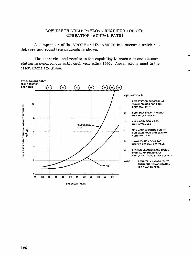
LOW EARTH ORBIT PAYLOAD REQUIRED FOR OTS OPERATION (ANNUAL RATE)
A comparison of the APOTV and the AMOOS in a scenario which has delivery and round trip payloads is shown.
The scenario used results in the capability to construct one 12-man station in synchronous orbit each year after 1995. Assumptions used in the
...
calculations are given.
SYNCHRONOUS ORBIT SPACE STATION CREW SIZE
10Q w
a a:
w a: I 8:r 1:1 W JI: ..J « :;:) l1li Z ..J 6 ~ \O~ I- iii a: 0 :r 4I-a: « w
~ ..J
2
0
..
ASSUMPTIONS:
(1) FIVE STATION ELEMENTS AT 150,000 POUNDS FOR EACH FOUR MAN UNIT.
12) FOUR MAN CREW TRANSFER ON SINGLE STAGE OTS.
(3) CREW ROTATION AT 90· DAY INTERVALS.
(4) ONE MANNED SORTIE FLIGHT FOR EACH FOUR MAN STATION CONSTRUCTION.
(5) 30,000 POUNDS OF CARGO NEEDED PER MAN PER YEAR.
(5) STATION ELEMENTS AND CARGO CARRIED ON MIXTURE OF SINGLE AND DUAL STAGE FLIGHTS .
NOTE: RESULTS IN CAPABILITY TO BUILD ONE 12 MAN STATION PER YEAR BY 1995.
85 66 81 88 89 90 91 92 93 94 85 96
CALENDAR YEAR ..
186
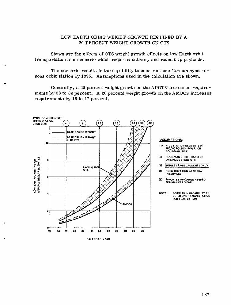
•
LOW EARTH ORBIT WEIGHT GROWTH REQUIRED BY A 20 PERCENT WEIGHT GROWTH ON OTS
Shown are the effects of OTS weight growth effects on low Earth orbit transportation in a scenario which requires delivery and round trip payloads.
The scenario results in the capability to construct one 12-man synchronous orbit station by 1995. Assumptions used in the calculation are shown.
Generally, a 20 percent weight growth on the APOTV increases requirements by 33 to 34 percent. A 20 percent weight growth on the AMOOS increases requi rements by 16 to 17 percent.
SYNCHRONOUS ORBIT SPACE STATION CREW SIZE
10~-----+------+------+------~--~~~~--~
I-m ::t: -I 8 (!l'"_ 0 IJJ ...3:I lil iii a: a: -o is 6::t: IJJ I- a: a: -I « « IJJ :::l
§ ~ -I «
4
D~~~-L__~__~__~~__~__~__~~__~__~ 85 Ss 87 SS SII 110 91 92 93 114 115 116
CALENDAR YEAR
ASSUMPTIONS:
111 FIVE STATION ELEMENTS AT 150,000 POUNDS FOR EACH FOUR-MAN UNIT
(21 FOUR-MAN CREW TRANSFER ON SINGLE STAGE OTS
(31 ISINGLE STAGE LAUNCHES ONLY I
(4) CREW ROTATION AT 9D·DAY INTERVALS
(51 30,000- LB OF CARGO NEEDED PER MAN PER YEAR
NOTE: RESULTS IN CAPABILITY TO BUILD ONE 12·MAN STATION PER YEAR BY 1985
187

ACCUMULA TIVE LOW EARTH ORBIT WEIGHT REQUIRED FOR OTS OPERATION
Shown is a comparison of the APOTV and the AMOOS in a scenario which has delivery and round trip payloads.
The scenario results in the capability to construct one 12-man station in synchronous orbit each year after 1995. Assumptions used in the calculations are given.
SYNCHRONOUS ORBIT SPACE STATION CREW SIZE 12
~r------+------~------+-----~'------+--~~
~ ~r------+------~------+-----~-------++---~ II: o x lII: _
PROP LSIVE OTS
~ ~ ~r------+------~------+-----~,---~-+----~ ~!t>o..J=W >
~ :l :0 :l
~
188
~~-----+------~------+-----~~----~~--~
10~-----4------~----~~----~__-----+------~
0~==~==~__~~__~__-1__~ 86 86 87 88 89 90 91 92 93 94 95 96
CALENDAR YEAR
ASSUMPTIONS:
111
(2)
(31
141
(5)
(6)
FIVE STATION ELEMENTS AT 150,000 POUNDS FOR EACH FOUR MAN UNIT.
FOUR MAN CREW TRANSFER ON SINGLE STAGE OTS.
CREW ROTATION AT 9O-DAY INTERVALS.
ONE MANNED SORTIE FLIGHT FOR EACH FOUR-MAN STATION CONSTRUCTION.
50,000 POUNDS OF CARGO NEEDED PER MAN PE.R YEAR.
STATION ELEMENTS AND CARGO CARRIED ON MIXTURE OF SINGLE AND DUAL STAGE FLIGHTS.
NOTE: RESULTS IN CAPABILITY TO BUILD ONE 12-MAN STATION PER YEAR BY 1995.
..

DUAL SHUTTLE LAUNCH AMOOS CONCEPTS SOLID BOOST OR LOX TRANSFER
This chart was prepared to determine the trends to be expected as a result of the selection of various OTS concepts using dual launches with lox transfer or solid boost.
The significant points to be seen are the effects of Shuttle capability and the effects of the size selection of the OTV.
Low Earth orbit basing of certain OTV elements will also affect the issues being considered.
70
LEGEND:
AMOOSIPAYLOAD AND SOLID 60MOTOR lAMOOS DESIGNED TO SHUTTLE CAPABILITY)
------.-50
iii... ~ Q 40 « 9AMOOS/PAYLOAD AND SOLID >MOTOR tAMOOS DESIGNED «...FOR 125K SHUTTLE CAPABILITY) >II: 30 /JJ:>-------- :::l
AMOOS/PAYLOAD AND LOX /JJ Q
TANK lAMOOS DESIGNED TO MAXIMUM SINGLE SHUTTLE LAUNCH ROUND TRIP CAPA- 20 BILlTY)
10
o
•
v~ .. . / ..,?..
~ t7 ","' , .... .. ...
/'<
V '-"'" - SOLID BOOSTERS
~/
V~f--~-~
~V \ '- LOX TRANSFER ONLY
! I
.....
;::;::. I
!
50 70 80 90 100 110 120 130
SHUTTLE CAPABILITY 11000 LBI
189

SUMMARY AMOOS - SOLID BOOST CAPABILITIES FOR SINGLE AND MULTIPLE SHUTTLE LA UNCHES
Shown here are summary data on the range of solid boosted AMOOS configurations being considered. The single launch AMOOS data are shown for reference.
Note: Multiple launch data shown are very preliminary because the total conceptual design iteration was incomplete when multiple launch performance was calculated. The data are accurate only to 5 to 10 percent for the multiple launch concept.
The solid boost concepts, to date, have been considered only as competitors to liquid boost conc~pts. If low Earth orbit basing of some OTS elements is considered, more solid motor capability could be used and increase maximum delivery payload more.
iii ..J
~ ~ :; iii <C :1t u >a: \II >::; w 0
190
6Or-----~----~------~----~------~----~----__,
60
40
20 ASSUMPTION:I-------I------I----,=--"'f==--------+-------+-----.=;:=-=----I AMOOS SIZED FOR OPTIMUM
0 60 70 80 90 100 110 120 130
SHUTTLE CAPABILITY 11000 LBI
NOTE: THE THREE SHUTTLE LAUNCH CASE IS OPERATED WITH A VERY LOW LOAD FACTOR. THE TWO SHUTTLE LAUNCH CASE SUFFERS ONLY A LOW LOAD FACTOR PENALTY.
PERFORMANCE WITH ONE SHUTTLE LAUNCH FOR EACH SHUTTLE.
!!
•
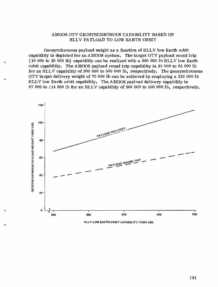
AMOOS OTV GEOSYNCHRONOUS CAPABILITY BASED ON HLLV PAYLOAD TO LOW EARTH ORBIT
Geosynchronous payload weight as a function of HLLV low Earth orbit capability is depicted for an AMOOS system. The target OTV payload round trip (10 000 to 20 000 lb) capability can be realized with a 300 000 lb HLLV low Earth orbit capability. The AMOOS payload round trip capability is 38 000 to 65 000 lb for an HLLV capability of 300 000 to 500 000 lb, respectively. The geosynchronous OTV target delivery weight of 70 000 lb can be achieved by employing a 310 000 lb HLLV low Earth orbit capability. The AMOOS payload deliveIjT capability is 67 000 to 114 000 lb for an HLLV capability of 300 000 to 500 000 lb, respectively.
120~
-------- -
o 300 350 400 450 500
HLLV LOW EARTH ORBIT CAPABILITY 110001 LBS.
191
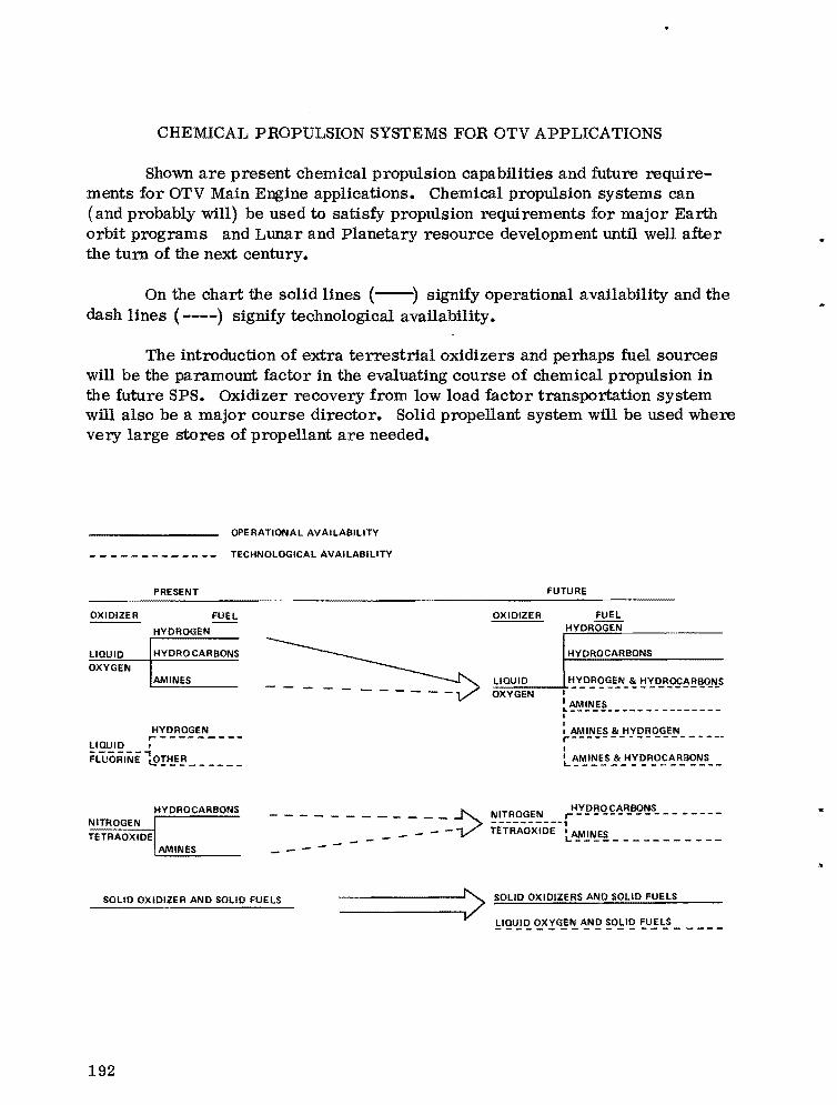
---
CHEMICAL PROPULSION SYSTEMS FOR OTV APPLICATIONS
Shown are present chemical propulsion capabilities and future requirements for OTV Main Engine applications. Chemical propulsion systems can (and probably will) be used to satisfy propulsion requirements for major Earth orbit programs and Lunar and Planetary resource development until well after the tum of the next century.
On the chart the solid lines (--) signify operational availability and the dash lines (----) signify technological availability.
The introduction of extra terrestrial oxidizers and perhaps fuel sources will be the paramount factor in the evaluating course of chemical propulsion in the future SPS. Oxidizer recovery from low load factor transportation system will also be a major course director. Solid propellant system will be used where vety large stores of propellant are needed.
OPERATIONAL AVAILABILITY
TECHNOLOGICAL AVAILABILITY
PRESENT FUTURE
OXIDIZER FUEL OXIDIZER FUEL HYDROGENHYDROGEN
HYDROCARBONS HYDROCARBONS
OXYGEN AMINES
L10UID
:::LI~OU:,::I:=.:D-:---+,!Y_D~~l!E..N_~ !:!!~R~~!!,!~"!.S OXYGEN I
~~~~~---------------I I
HYDROGEN I AMINES & HYDROGEN r-------- r------------------LlOUID I IFlllORINE i.9!l!E~_____ _ L~~I~E..S.!It_H!,::!R_O£~F!.B~~S__
HYDROCARBONS HYDROCARBONS .. ------______ :> r------------ ----NITROGEN NITROGEN ------ ----,
_ _ _ L ______________ _ ___ - - TETRAOXIDE I AMINESTETRAOXIDE
AMINES
SOLID OXIDIZER AND SOLID FUELS
192

EFFECTS OF ENGINE PERFORMANCE AND STAGE LENGTH (AMOOS)
Shown here are the effects of engine performance and stage length for a given A MOOS type propulsion system. Transportation savings shown represent only savings in flights •
.. As noted, no savings in stage or engine system weight was included. It
is expected that savings to be expected from these factors will also be positive and significant. It is also expected that the cost of building a unique short stage may be offset by savings in building longer cargo bays for lower stages.
Unique engines and unique stage designs are probably needed.
BASELINE DATA:
TOTAL WEIGHT STAGE AND PAY· LOAD =63, 100 L8
ROUND TRIP PAYLOAD =8,000 L812 ~
DELIVERY PAYLOAD = 13,000 L8en Z " Isp = 456 S :;;;a STAGE WEIGHT =6,500 L8 z 0 8i=
SENSITIVITIES:~ a: 0 Isp FOR ROUND TRIP =O.57%/SEC"en
Isp INCREASE (SEC)~ a:... STAGE LENGTH ·l.l%/FT4
LENGTH FACTOR:
CARGO 8AY WEIGHT IS ABOUT 685 L8/FT.
Isp FOR DELIVERY = 0.46%ISEC
NOTE: NO SAVING FOR STAGE OR ENGINE SYSTEM WEIGHT REDUCTION IS INCLUDED. CASE SHOWN IS FOR DELIVERY ONLY •
•
193

EXAMPLE - TRADES TO BE MADE IN ENGINE SELECTION (AMOOS CONFIGURATION - 80K SHUTTLE)
Shown here are example engine trades to be made for engine selection for OTV.
All baseline OTV stage data have been developed using the RL10-IIB engine system. Trades for engine selection will be compared against the RL10-IIB. In the example, cases involving a possible change in the RLIO-IIB and introducing a new engine (ASE data used) are typical of trades to be made. Stage data have been parameterized to accommodate these trades.
It can be noted from the examples that interface transportation element (the Shuttle cargo bay in this instance) problems have significant effects on engine selection.
CHANGE TO BASELINE ENGINE
BASELINE ENGINE (RC10-IIB)
RET LENGTH .. 55 IN •
.. 456.5 SEClip
WEIGHT .. 442 LB.
€ 0200:1
MR o 6:1
PC .. 400 PSI
\::l C! NEW ENGINE (ASE) NEW ENGINE (ASE)
RET LENGTH 0471N RET LENGTH .. 48 IN.
.. 471 SEC Isp .. 4&4.5 SEC liP
.. 320 LB WEIGHT .. 310 LB. WEIGHT
e 0400€ .. 400S 7:1MR .. 6:1 MR ..
.. 1400 PSIo ~ 1400 PSI PCPC
C! EFFECTS ON TRANSPORTATION V
•
6:1 7:1
SHUTTLE/STAGE LENGTH +0.6% +2.8%
+7.3% +4.0%lIP ENG WEIGHT +1.6% +1.5%
+8.3%NET RESULT +9.5%
• REDUCE CARGO BAY LENGTH REOUIRED BY 3 TO 4 FEET. CHART.1OF .a.
194

SOLID ROCKET MOTOR PARAMETER DATA
The two mass fraction curves represent current (bottom curve) state-ofthe-art, and the top curve ..is an estimate of 1980 state-of-the-art. Both curves should be used with an I of 300 sec. Solid propellant performance (I ) is
sp sp .. currently at the upper limit•
The dotted curve shows the motor case diameter for a length-to-diameter ratio of 0: 8. To get the total motor length, a nozzle length must be added.
1.0
""~~~ ... ,, ,.. ."". \,\0"
c,t-~,::::::---~ ,
" 4 ~ ~ /
50 100 150
MOTOR WEIGHT (1000 LB)
250
0.98 200
-z -z a:0 150 w0.96
~~ w ::iE~ <t:a:
u. Q en w100 en:l 0.94
<t:::iE (.)
0.92 50
0.90 o o 200
..
195
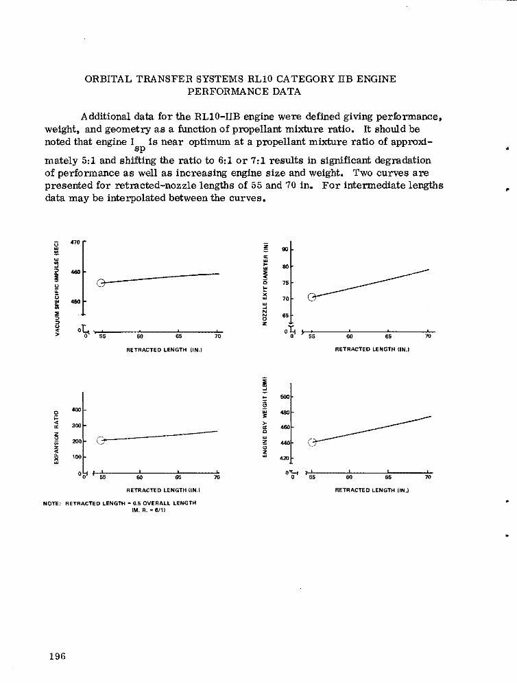
ORBITAL TRANSFER SYSTEMS RL10 CATEGORY IIB ENGINE PERFORMANCE DATA
Additional data for the RLIO-IIB engine were defined giving performance, weight, and geometry as a function of propellant mixture ratio. It should be noted that engine I is near optimmn at a propellant mixture ratio of approxi
sp mately 5:1 and shifting the ratio to 6:1 or 7: 1 results in significant degradation of performance as well as increasing engine size and weight. Two curves are presented for retracted-nozzle lengths of 55 and 70 in. For intermediate lengths data may be interpolated between the curves.
470'i3 !!'" en '" -' ~ 480 Ii 5.! .... U
480'" ij ~ ::> ::>
~ 90 a: ...'" '"~ 80
0(
O 75G!: X w 70 w -' N N 650 z
U 0( oL. I , I I o~ j , I I I> o 55 60 65 70 0 55 60 65 70
RETRACTED LENGTH tiN.) RETRACTED LENGTH UN.'
i = 500I::I: S!400 w 4800 3:i= « >
IX: 300 IX: 480 c w~ Z;;; 200 G (;
440 :z « z Q. 100 w 420X w
, ,I I I ~ I I I00 I o~55 60 65 70 55 60 65 70
RETRACTED LENGTH tiN.) RETRACTED LENGTH IIN.I
NOTE: RETRACTED LENGTH =0.5 OVERALL LENGTH (M. R. =6/11
..
196
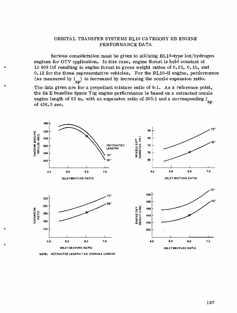
ORBITAL TRANSFER SYSTEMS RL10 CATEGORY IIB ENGINE PERFORMANCE DATA
Serious consideration must be given to utilizing RL10-type lox/hydrogen engines for OTV application. In this case, engine thrust is held constant at
• 15 000 Ibf resulting in engine thrust to gross weight ratios of 0.23, 0.15, and 0.12 for the three representative vehicles. For the RL10-ll engine, performance (as measured by I ) is increased by increasing the nozzle expansion ratio.
sp• The data given are for a propellant mixture ratio of 6: 1. As a reference point,
the S& E baseline Space Tug engine performance is based on a retracted nozzle engine length of 55 in. with an expansion ratio of 205:1 and a corresponding I of 456. 5 sec. sp
465
u 460 ii:-uuw 455w'"11.
"'w :!!'" 450:::> .... :::>~u:!! 445«>
440
70"85
80I-Z x= 55" wa:(RETRACTED 75WW
LENGTH) .... 1NWN:!!0« 70
70" Zo
55" 65
4.0 5.0 6.0 7.0 4.0 5.0 6.0
300
250 Z Qo
200"'zl«« 11. a: X 160W
100
INLET MIXTURE RATIO INLET MIXTURE RATIO
70"
50070"
55" 55"
480
~i 460 c=! wI 440~J: t!)t!) z
420w~
400
4.0 5.0 6.0 7.0 4.0 5.0 6.0 7.0
INLET MIXTURE RATIO INLET MIXTURE RATIO
NOTE: RETRACTED LENGTH = 0.5 OVERALL LENGTH
7.0
197

ORBITAL TRANSFER SYSTEM RL10 CATEGORY IV ENGINE PERFORMANCE DATA
Significant performance improvement is attainable by utilizing the RL10IV engine for the OTV stages. Parametric data are given for an engine of 15 000 lbf at a propellant mixture ratio of 6: 1. The dotted vertical lines on the chart represent the practical upper limit of approximately 470 sec I for expander cycle engines. sp
475
2 IL-0 - 470 Ow ......."' -'" .... 465 :!!~ ::>::>::> ... 460~i!! :>
455
600
500 ~ ;;;
0 400t... X ~ w II: 300
200
80
70I X ~
II:w .... 60w... l-WN
N :!! 500 « z i5 40
50 55 60 65 70 50 55 60 65 70
RETRACTED LENGTH (IN.' RETRACTED LENGTH (IN.l
470
l;: i 460 (:) :::! .... I- 430 z :z: (; CJ z iii 410 w ~
390
50 55 60 65 70 50 55 60 65 70
RETRACTED LENGTH (IN.' RETRACTED LENGTH UN.'
NOTE: RETRACTED LENGTH: 0.5 OVERALL LENGTH MR- 6/1 F - 15,000 1bf
198

ORBITAL TRANSFER SYSTEM PLUG CLUSTER OPTION
An attractive alternative to using conventional bell nozzle engines such as the ASE or RLI0 is the grouping of multiple small engines in a "plug cluster" geometry. For OTS application, we have selected a lox/hydrogen engine of 1500
.. lb thrust arranged in a circular fashion around an aerodynamically designed nozzle cone for illustration. The individual nozzle expansion ratio is 40: 1; however, when appropriately arranged in the plug cluster geometry, the collective expansion ratio is 400:1, resulting in an effective I of 466 sec. The number
sp of individual engine modules may be varied to adjust the total thrust as desired. The nominal propellant mixture ratio is 6: 1.
The operation of the plug cluster is necessarily sensitive to geometrical arrangement. For performance and stage conceptual layout purposes, the geometric relationships as they are presently theorized have been defined. The radius, R
E , which defines the circle circumscribing the cluster of individual
engines, is determined by selecting the desired performance level (effective expansion ratio) and the desired total thrust (number of engines), and by specifying the throat diameter of the individual engine. From this, the geometry of the central nozzle cone is determined by the relationships shown. Nominal separation of the individual engine nozzles is 2 in. For OTV application, the individual nozzles are canted slightly inward to direct exhaust product flow along the central nozzle cone surface.
The plug cluster design is presently undergoing conceptual evaluation and, therefore, must be considered only as theoretically attractive at this time, pending feasibility analysis and the usual demonstration testing.
PLUG CLUSTER PERFORMANCE DATA
• EACH ENGINE MOOULE HAS 1600 LBF
• LOX/LH2 PROPELLANTS
• INDIVIDUAL EXPANSION RATIO IS 40/1
• COLLEcnVE EXPANSION RAno IS_/1
• EFFECTIVE SPECIFIC IMPULSE IS _ SEC
• • MIXTURE RATIO - 6/1
RIRE - 0.7
X/AE - 0.81
RE • «EFF,N. Dl/411!o
WHERE: < - EFFECTIVE EXPANSION RATIO
Dt - ~~~~~:~ROAT
N • NUMBER OF ENGINES
199
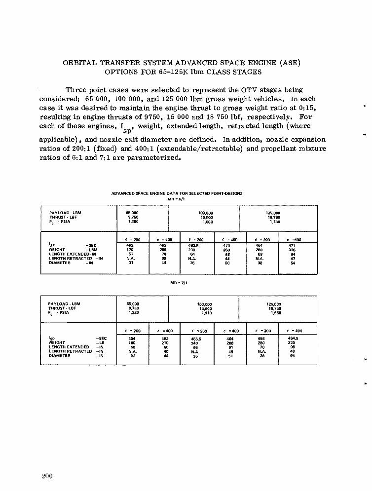
ORBITAL TRANSFER SYSTEM ADVANCED SPACE ENGINE (ASE) OPTIONS FOR 65-125K Ibm CLASS STAGES
Three point cases were selected to represent the OTV stages being considered: 65 000, 100 000, and 125 000 Ibm gross weight vehicles. In each case it was desired to maintain the engine thrust to gross weight ratio at 0:15, resulting in engine thrusts of 9750, 15 000 and 18 750 lbf, respectively. For each of these engines, I , weight, extended length, retracted length (where
sp applicable), and nozzle exit diameter are defined. In addition, nozzle expansion ratios of 200: 1 (fixed) and 400: 1 (extendable/retractable) and propellant mixture ratios of 6: 1 and 7: 1 are parameterized.
ADVANCED SPACE ENGINE DATA FOR SELECTED POINT·DESIGNS MR = 6/1
PAYLOAD· LBM 65,000 100.000 125,000 THRUST· LBF 9,750 15,000 18,750 Pc . PSIA 1,380 1.600 1,730
€ = 200 € =400 € = 200 € 400 € =400
'SP -SEC 462 469 463.5 470 464 471 WEIGHT -LBM 170 200 230 260 260 310 LENGTH EXTENDED ·IN 57 78 64 88 68 94 LENGTH RETRACTED -IN N.A. 39 N.A. 44 N.A. 47 DIAMETER -IN 31 44 35 50 38 54
PAYLOAD . LBM 65,000 100,000 125,000 THRUST· LBF 9,750 15,000 18.750 Pc • PSIA 1.280 1,510 1,650
€ -200 e =400 e =200 e =400 e - 200 e =400
'spWEIGHT LENGTH EXTENDED LENGTH RETRACTED DIAMETER
-SEC -LB -IN -IN -IN
454 180 58
N.A. il2
462 210
80 40 44
455.5 240 66
N.A. 36
464 280
91 46 51
456 280 70
NA 38
464.5 320
96 48 54
..
200
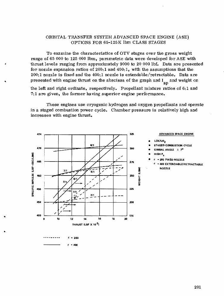
ORBITAL TRANSFER SYSTEM ADVANCED SPACE ENGINE (ASE) OPTIONS FOR 65-125 K Ibm CLASS STAGES
To examine the characteristics of OTV stages over the gross weight range of 65 000 to 125 000 Ibm, parametric data were developed for ASE with thrust levels ranging from approximately 9000 to 20 000 lbf. Data are presented for nozzle expansion ratios of 200:1 and 400:1, with the assumptions that the 200:1~nozzle is fixed and the 400:1 nozzle is extendable/retractable. Data are
.. presented with engine thrust on the abscissa of the graph and I and weight on sp
the left and right ordinate, respectively. Propellant mixture ratios of 6:1 and 7:1 are given, the former having superior engine performance.
These engines use cryogenic hydrogen and oxygen propellants and operate in a staged combustion power cycle. Chamber pressure is relatively high and increases with engine thrust.
474
470
i C (,) .... 466
<f III ,:;! .... '" 482-l ::l... ! !:! II. 458U .... Ils
4Ii4
• 450
~ 611 ~
-~V r
" "" ""
I
I .,
~-if -r
L,3! 7 6/1 ... "" - /
Y " ,
~ " "" "
;'
" "",,
--;;I' .. ""
;'
V 7/1" '" "
~ ." "" f-:- --" , "'~ "
"" 7/1- - -- --
/' /
/ /
It
ADVANCED SPACE ENGINE
• LOX/LH2 • STAGED COMBUSTION CYCLE
300 • GIMBAL ANGLE ±-,o • HIGH Pc
• f - 200 FIXED NOZZLE 275
e - 400 EXTENDABLE/RETRACTABLE
i NOZZLE
,:;! 250 ...
J: CI iii lI:
225
200
175 8 10 12 14 16 18 20
THRUST (LBF X 10.3 ,
• e - 200
e = 400
201


..
•
APPENDIX C
OTV - MSFC STUDY PARTI CI PANTS
203

I\:l 0..,.
Name
Billy A. Neighbors Norma Terrell Reba Kozub
Douglas Westrope Oliver l\Ieredith A rchie Young James Thompson James Sanders Gene Whitaker Ken Turner John Belcher Stephen Hall Max Akridge
Larry Brandon Bert Willis Richard Klan Richard Kramer George Kearns Carl Fritz
OTV-l\ISFC STUDY PARTICIPANTS
Participation
Study Leader Secretary - Report Preparation Editorial Clerk - Report Preparation
Principal Contributors
Systems Analysis Design Analysis Performance Analysis Engine Systems Propulsion Systems Costing Analysis Schedule Analysis Operations/Capture Analysis Large Payload Capability Requirements Concept Comparison/Evaluation
Other Contributors
Guidance and Navigation System Communications System Cost Analysis Liquid Propulsion Solid Propulsion Thermal Evaluation
Organization Telephone
PD01 205/453-4161 PD01 205/453-4160 PD01 205/453-4162
PD24 205/453-4195 PD23 205/453-3569 PD32 205/453-3479 PD13 205/453-3228 PD13 205/453-3229 PP03 205/453-0467 PP02 205/453-3216 PD34 205/453-3936 PD24 205/453-4196 PD31 205/453-4721
PD12 205/453-5727 PD14 205/453-5728 PP03 205/453-1034 PD13 205/453-3228 PD13 205/453-3228 PD22 205/453-4263
.. •
APPROVAL
ORBIT TRANSFER SYSTEMS WITH EMPHASI S ON SHUTTLE APPLI CATIONS - 1986-1991
By Program Development
The information in this report has been reviewed for security classification. Review of any information concerning Department of Defense or Atomic Energy Commission programs has been made by the MSFC Security Classification Officer. This report, in its entirety, has been determined to be unclassified.
This document has also been reviewed and approved for technical accuracy.
aa/l~e~~ -~~ CHARLES R. DARWIN HERMAN P. tbIEROW Director, Preliminary Design Office Director, Payload Studies Office
BILL H. SNE ED Director, Program Planning Office
..
tru. s. GOVERNMENT PRINTING OFFICE 1977-740.Q49/322 REGION NO.4
205

DISTRIBUTION
INTERNAL EPll PS03 EXTERNAL Mr. Kroll Mr. Dudley
EAOI Scientific and Technical IDformattOll Mr. Kingsbury EPl3 PS04 Facility (25) Mr. Belew Mr. EDgier Mr. Cramblit P.O. Box 8757
Baltimore/Washington Inter.-tiona! EEOI EP21 PS06 Airport
Mr. Maraball Mr. Lombardo Mr. Carey Baltimore, MD 21240 Mr. Chandler
EROI Mr. Rodgera POOl NASA Headquarters Dr. Dozier Mr. Reed Mr. Darwin Attn: MT!Mr. Disher Mr. Attaya Mr. Neighbors MTD/Mr. Freltq
FPS1 Mrs. Kozub (150 c'.rs) MTE/Mr. JobnllOn (5) EFOI Mr. Verble PorrG/Mr. Savage (5)
Mr. Powell (2) POll MV/Mr. Mahon EP41 Mr.Dlgen MVE/Mr. McGolrlck (5)
ECOI Mr.H~ MVU/Dr. Wild (3) Mr. Moore PDl3 O/lIlr. CulbertlOn (4) Mr. Chase ELOI Mr. Sanders Washington, D.C. 20546
Dr. Thom88Oll Mr. TbompaOll ECll Mr. Kramer Johnson Space Center
Mr. Aden ELll Mr. Kearns Attn: EAIDr. Faget Mr. Kurt.. ER/Mr. Davie (5)
EC21 PD14 Houston, Texas 77058 Mr. Mack EU1 Mr. Boehme
Mr. Lindberg (3) Mr. Willia Lsngley Resesrch Center EC31 Attn: 365/Mr. He!ll'y
Dr.RaDdall EU1 PD21 365/Mr. Rehder Mr. Huff Mr. Gregg Hampton, VA 23365
EC41 Mr. Garrett EL51 PD22 Edwards Air Force Base
Mr. labell (3) Mr. Denton Attn: Curt Selph (2) Eool Mr. Fritz AFRPL LKCB
Dr. Lov.lngood ETOI Edwards, California 93523 Mr. Cagle (3) PD23
EDll Mr. Colley Mr. Blair SAOI Mr. Meredith
Mr. Lindstrom ED21 PD24
Mr. Ryan PAOI Mr. Shelton Mr. Murphy Mr. Westrope
ED31 Mr. Downey Mr. Hall Mr. Dahm
PMI PD31 ED32 Mr. Sneed Mr. Harrla
Mr. JobnllOn Mr. Akridge PP02
mOl Mr. Ferguaon (2) PD32 Mr. Schwinghammer Mr. French Mr. Cataldo PM3 Mr. Youug
Mr. Rutledge (5) Elill PD33
Dr. Gause PP04 Mr. Croft Dr. Dav.la
EH21 PD34 Mr. Herring PF02 Mr. Pavlick
Mr. Teir (5) BC31 CC01 1
Mr. Curry PFIO Mr. Huber AS61 (2)
Eli41 Mr. Currie I Mr. Franklin AS6lL (8)
PSOI ESOI Mr. Glerow ATIll
Dr. Lundqul.t Mr. Speara Mr. Smith
EMI PS02 Mr. McCool Mr. Ballance