c-mod plasma boundary program · c-mod plasma boundary program presented by b. lipschultz...
TRANSCRIPT

C-Mod Plasma boundary program
Presented by B. Lipschultz
Contributions from B. Labombard,S. Lisgo, J. Terry, D. Whyte, S.
Zweben & C-Mod group
General program description
Transport
Boronization studies
Divertor
D retention in molybdenum
Dust
ITPA contributions
Summary

Program Advisory Committee, January 25-27, 2006 2
C-Mod attributes lead to a capability to study important(and probably unique) aspects of edge physics
• 2-8 Tesla magnetic field (ITER 5.3 T)High parallel power density ( 0.5 GW/m2 approaching that of ITER)
High density
Short neutral mean free paths in SOL and divertor ideal for accessing ITER regimes(difficult or impossible for other tokamaks)
SOL opacity to neutrals and impurities - affecting fueling and impurity screening
Tests of divertor neutral viscosity, i-n and n-n collisions in models
Divertor radiation transfer - affecting the ionization/recombination balance and detachment
Divertor plasma densities spanning that of ITER
• High-Z Plasma Facing Components (ITER Be/C/W initially, all-W later?)D/T retention
Effects of high-Z PFCs on the core plasma and operational experience
Conditioning experience with high-Z PFCs
C-Mod’s parameters, materials and studies bring breadth to the US(and International) program

Program Advisory Committee, January 25-27, 2006 3
C-Mod Boundary physics program emphases
•Combining C-Mod unique characteristics with the goal of advancing the tokamakconcept brings emphases on
Edge plasma transportOur primary emphasis because it is the determining factor for heat and particleloadings, impurity sources and transport
Neutral physics affecting core, divertor and edge plasmasImpurities (sources, effects on core)
GOAL: Develop predictive capability scaleable to ITER & reactors
•We also identify and develop hardware and operational techniques in support ofadvancing the tokamak concept
Propose and develop high heat flux handling, particle and impurity controlmethods

Program Advisory Committee, January 25-27, 2006 4
C-Mod boundary transport research has severalemphases, rooted in understanding SOL transport
Understanding Scrapeoff Layer transport
Parallel transportCross-field transport
Microscopic, or turbulent transport
measurements/modeling
Macroscopic, or time-averaged
sense
Theory-basedDimensionless
scaling
Current transport descriptions are very inadequate, giving rise to large uncertainties in
Heat load profiles for divertor and walls (and surface lifetime)
Impurity sources and effect on core plasma
T retention processes and removal techniques
We need better measures, empirical and physics-based, of transport magnitude/scaling
Macroscopic, or time-averaged
sense
Theory-based Theory-based

Program Advisory Committee, January 25-27, 2006 5
The SOL appears to have different regions with differenttransport
• The regions ‘near’ and far from the separatrixexhibit different characteristics
Far SOLHigh turbulence levels, convective transport
Transport independent of local parameters
Near SOL (one density e-folding length)Less turbulence and less convectiveCross-field transport dependent on local *
• Picture emergingplasma filaments intermittently ‘peel away’from the edge of the steep-gradient, near SOLregion and freely propagate towards the wall.
Radial ion fluxes, and wall recycling, CANcompete with parallel flow to the divertor
0 5 10 15 20 25distance from separatrix (mm)
0.01
0.10
1.00
ne increasingn e
(10
20 m
-3)
{ ’nea
r
’far
’
limite
r
ITER second separatrix locationif scaled by machine size

Program Advisory Committee, January 25-27, 2006 6
Far SOL: Blob/filament propagation studies
•Filament size (||B & B) anddynamics
Several methods utilized•Scaling and inter-machine
comparisons of radial propagation arepresent emphasis (IEA/ITPA DSOL-15)
•Plans to expand to TJ-II, AUG, DIII-D, JT-60U
•Plans for comparisons of vr withtheory/modelling ongoing
Riso (Garcia/Naulin)Lodestar (Myra/D’Ippolito)
=[VR=1000,VZ=0] m/s
Z (
cm
)
separatrix
L-mode
87 88 89 90 91
Rmajor (cm)
-1.5
-2.5
-3.5
sh
ot
10
31
20
40
03
- t
=1
.15
00
5s
1.5 km/s 1-2 km/sVrad
1 km/s 5 km/sVpol
0.7 - 1.5 cm2-6 cmLrad
0.6 - 1.0 cm5-9 cmLpol
20-80 eV5-50 eVTe,edge
2 - 20x1019/m30.2 - 2x10¹⁹/m3nedge
4.4 T0.2- 0.3 TBedge
C-ModNSTX (Zweben)
radial velocity [m/s]
num
ber
of e
vent
s
(b)
-1000 0 1000 20000
10
20
30
40
1%Cs

Program Advisory Committee, January 25-27, 2006 7
New studies of ELM dynamics in the SOL
0.761 0.762
dBθ/dt
1050
6230
33 B
P1T
_GH
K
freq
uenc
y (k
Hz) 500
250
00 < f < 500 kHz
time (s)
dBθ/dt
0 2 4 6 8radial velocity (km/s)
0
2
4
6
# of
ELM
s in
ve
loci
ty in
terv
al
• Precursor oscillation observed - localized in pedestal - growth rate ~ 1x10⁵/s
• Complex structure observed in a single ELM event
• Collapse in pedestal results in radial propagating “primary” pulseVr from 0.5 - 8.0 km/s; radial pulse width ~ 0.5 cm
Reaches wall before divertor
• “Secondary” pulses follow “primary”
• Plans: compare observations with modelling of MHD stability and ELM dynamics(collaboration w/Leonard, Osborne @ DIII-D)

Program Advisory Committee, January 25-27, 2006 8
A number of turbulence studies are planned
• Comparison of blobs in limited/circular plasmas with simulations by B. Scott (IPP-
Garching)
Some experimental data already supplied to B. Scott (by PPPL)
Initial simulations started
• Add new lower-divertor view for more information about filaments (PPPL/MIT)
H-mode trigger near x-point? Poloidal extent of filaments?
• Radial view for structure parallel to B (PPPL/MIT)
• Purchase additional fast camera (PPPL), probably continuously recording (Phantom
7 or Photron APS-RX)
• Expand informal collaboration with Lodestar (Myra/D’Ippolito) to formal (i.e. PPPL
$) for continued work on blob dynamics and density limit physics.
• Implement wide angle view with with fast camera
Program Advisory Committee, January 25-27, 2006 9
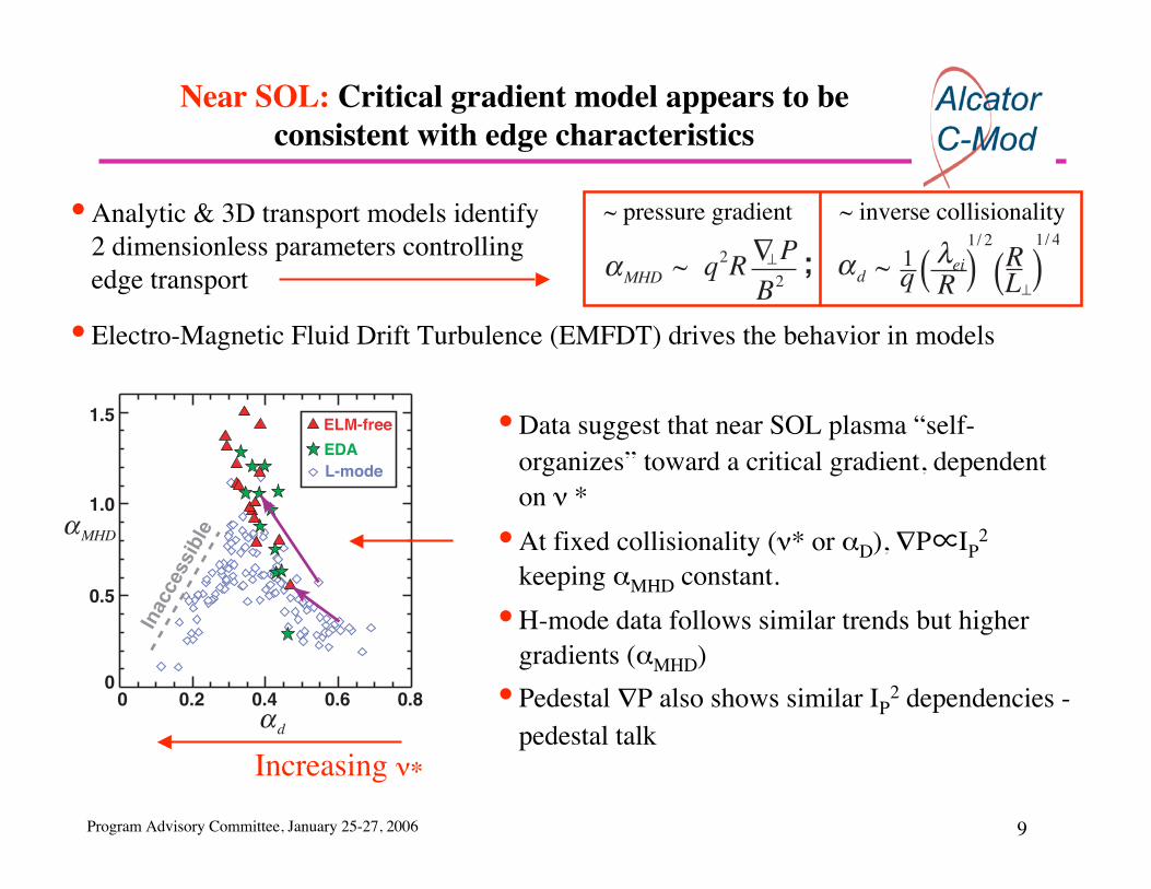
Near SOL: Critical gradient model appears to beconsistent with edge characteristics
• Data suggest that near SOL plasma “self-organizes” toward a critical gradient, dependenton *
• At fixed collisionality ( * or D), P IP2
keeping MHD constant.
• H-mode data follows similar trends but highergradients ( MHD)
• Pedestal P also shows similar IP2 dependencies -
pedestal talk
• Analytic & 3D transport models identify2 dimensionless parameters controllingedge transport
~ pressure gradient ~ inverse collisionality
• Electro-Magnetic Fluid Drift Turbulence (EMFDT) drives the behavior in models
αMHD ~P
B2q2R∇⊥ ~
1/ 2
qαd Rλei( )1 R
L⊥)(1/ 4
;
0 0.2 0.4 0.6 0.80
0.5
1.0
1.5
αd
αMHD
Inaccessib
le
ELM-free
EDAL-mode
Increasing

Program Advisory Committee, January 25-27, 2006 10
Magnetic topology also appears to affect attainablepressure gradients
• Note - ( ei/R)0.5/q is a better fitthan D
• Lower-null achieves higher gradients ( MHD)compared to upper-null
• We believe this difference is due to changes inflows in the SOL - another control parameter
• Plans:
Extend ( MHD, D) studies to higher B
New flow and ionization source diagnostics
0.1 0.2 0.3 0.4 0.5 0.60.0
0.2
0.4
0.6
0.8
1.0
αMHD
1/ 2
q Rλei( )1
0
1
2
0
1
2
0.1 0.2 0.3 0.4 0.5 0.6
1024
eV
m-4
1/ 2
q Rλei( )1
∇ nTe⊥
∇ nTe⊥
0.8 MA
0.4 MA
0.8 MA
0.4 MA
~R
Ln⎛
⎝ ⎜
⎞
⎠ ⎟
1/ 4
αd

Program Advisory Committee, January 25-27, 2006 11
Measurements from multiple machines point to alarge poloidal flow in the SOL
• Flow along B towards the inner divertor
Peaked at the inner midplane
Likely related to D/C co-deposition at inner divertor
Dependent on magnetic topology & B direction
• Difficult for codes to reproduce
ExB drifts & Pfirsch-Schluter effects reproduce Bdependence but not magnitude or poloidal variation
Experimental and modelling evidence for strong radial
transport @ outboard edge driving parallel flows
through pressure balance
• Also evidence of transport-driven flows setting toroidal
rotation boundary condition for confined plasma
• Plans: additional flow measurements in the SOL(probes) and pedestal (CXRS).
0
1
Flux-tube coordinate, S
Para
llel M
ach
Num
ber
0
0.5
1S
0 0.5 1
Inner SOLOuter SOL
C-ModJT-60UJET DIII-D(plumes)

Program Advisory Committee, January 25-27, 2006 12
0510 0
0.0-50
-250
2550
0
00
-50
-50
-25
0
25
50
Inner SOL
0510
Distance from Separatrix (mm)
-25
0
25
Outer SOL0 5 100 10
0 5 100
Parallel FlowVelocity (km/s)
Flows defined by magnetic AND/OR mechanical geometry -divertor or limited, again connecting to H-mode threshold
• Lower-limited, grazing, lower X-pointequilibria have co-current inner SOLflows (not USN or inner-wall limited!)
Lower inner divertor recycling incommon
Each have a low H-mode threshold
Flows towards the inner divertor are theconsistent characteristic
• Plans:New inner wall probes
New probe heads (poloidal and toroidalMach flows)
CXRS (inner and outer edge)

Program Advisory Committee, January 25-27, 2006 13
UEDGE modeling of SOL flows is yielding insights intopotential drive mechanisms
Plans (2006-2007)• UEDGE to be enhanced to
handle near DN equilibria(Rognlien - LLNL)
• Model upper/lower x-point andnear double-null discharges
• => determine LFS/HFStransport asymmetry from C-Mod data
(A collaboration with A. Pigarov & S. Krasheninnikov, UCSD)
• C-Mod high-field SOL, near-sonic parallel flows, can be reproduced in UEDGEif cross-field transport coefficients have strong poloidal asymmetry1
• Cross-field transport at the LFS midplane is predominantly convective; Vconv(sep) = 6m/s; Vconv (wall) = 160m/s
LFS/HFS radial transport asymmetry factor of 20:1
Blue - probe data
Red - UEDGE
1 A. Pigarov et al., presented at 10th InternationalWorkshop on Plasma Edge Theory in Fusion Devices
OuterScanningProbe
Inner ScanningProbe
108
1
DivertorProbes
1
5
9
1316
5

Program Advisory Committee, January 25-27, 2006 14
Inner-wall scanning probe diagnostic will allow detailedinvestigations of inner SOL plasma flows/profiles
• Two new inner wall scanning probes (WASPs) are tobe installed in 2006 (grad student - N. Smick)
Probe actuated by embedded coil and ambientmagnetic field4 electrodes ==> Langmuir/Mach probeLinear plunge motion (+R direction)
• Prototype tested in 4T field last summer• Final version to be tested prior to installation (next
break)
B
B
B
Wall Actuated Scanning ProbeN. Smick, B. LaBombard
• Goals: Record key data in high field SOL (relativelyfree of ICRF sheath rectification effects):
Parallel & perpendicular flowsFluctuations, fluctuation-induced transport
=> inward pinch?=> quasi-coherent mode amplitude in EDA H-mode?
Density, temperature, potential profiles

Program Advisory Committee, January 25-27, 2006 15
Advanced, high-heat flux probes to be tested in 2006• Goal: install on all 4 scanning probe systems
Parallel/perpendicular Mach probe geometrySelf-shadowing, tungsten electrodes
• Prototype fast sweep I-V probe drive electronics to betested in 2006 (grad student - L. Lyons)
Graduate student thesis projectProof of principle operation in 2006 on A-port probe
Voltage sweep rate >~ 1 MHzRecord Te, ne, fluctuations
• New Langmuir probe array in upper divertorInstalled as part of upper divertor/cryopump upgrade
Additional probe diagnostic enhancements are plannedfor boundary layer physics studies
Inner DivertorProbe Array
1
12
8
4
16
108
31
6 Outer Probe Array
C
G
D
Vertical ScanningProbe
HorizontalScanning Probe
Upper Probe Array
1 6 10 14
WallScanningProbes (2)
B

Program Advisory Committee, January 25-27, 2006 16
Boronization was a central focus of the 2005 experimentalcampaign
•At the end of the 2004 campaign
The majority of Mo tiles were covered with thick B layers (~6µm thick)
(note: such thick, widespread, layers are also common in carbon PFC tokamaks)
•All surfaces cleaned of accumulated boron during vacuum break
Surface analysis showed B/(Mo+B) dropping from 99% to 10-20%
B likely ‘trapped’ in the topography of the surface
•All BN tiles replaced with molybdenum
•Long operational period before boronization to properly characterize un-
boronized PFC operation.

Program Advisory Committee, January 25-27, 2006 17
Boronization is very important for plasma performance
• Molybdenum is the primary radiator beforeboronization (no B on walls)
• Fe and Mo fractions approaching 0.1%
• First boronizationLarge drop in molybdenum & iron
Layer wears off in 10s of shots
• Second boronizationMolybdenum levels drop further
• Molybdenum radiation rises after eachboronization - indications are that smallregions (10-1000 cm2) are involved
• Iron radiation stays low after first boronizationLong-term coating of most surfaces
0.0
0.5
1.0
1.5
2.0
P RA
D,Z
(M
W)
0 20 40 60 80 100discharge sequence
10-5
10-4
n Z/n
e
MoFe
1st 2ndboronizations

Program Advisory Committee, January 25-27, 2006 18
Boron coating erosion rate correlates with RF energyinjected
• General trend seen after eachboronization
Radiation low and stored energy high fora period
Followed by impurity increases andconfinement degradation
Confinement degradation occurs at ~ 50MJ input energy (for RF-heating)
• For Ohmic H-modes the degradationappears not to occur as quickly
~3-4 times as much input energy toachieve the same degradation
=> enhancement of sheaths in edge maybe leading to enhanced erosion and Mosource
1050
610
Discharges after boronization
Wto
t (kJ
)
1000 10 20 30 40 50
150
200
250PRF = 3 MWPRF = 4 MW

Program Advisory Committee, January 25-27, 2006 19
There is a clear correlation between higher impurityradiation and degraded confinement
0.0 0.2 0.4 0.6 0.8 1.00.0
0.5
1.0
1.5
2.0
PRAD/PIN
HIT
ER
,89
Pre-boronizationPost-1st-boronizationPost-2nd-boronization
H L
• Mo radiation losses lead to a cooler pedestal
• Profile stiffness causes Te and Pe to decrease across the entire profile
Lower stored energy and H-factor
• Reducing Mo (replaced w/B) leads to hotter pedestal and higher H-factor
Molybdenum radiation efficiency in C-Mod like W radiation in ITER
0 1.00.5 1.5 2.0Pe,95 (1023 eV/m3)
0.0
0.5
1.0
1.5
2.0
HIT
ER
,89
Pre-boronizationPost-1st-boronizationPost-2nd-boronization
H L

Program Advisory Committee, January 25-27, 2006 20
Boronization has a short-term effect on recycling and Dretention
After an overnight boronization
• Amount injected to achieve the desired densityvery small
• Walls are fueling (R > 1)
• Gas seems to be coming from PFC surfacesnear the midplane
• The recycling effects are mostly worn off after50 shots
PFC surfaces shift from dominant fueling toalmost pumping
• Long after boronization PFC surfaces pump
Recycling effects following a boronization
10
50
61
0
10
20
30Gas injected
-40
-20
0
(To
rr-l)
(To
rr-l)
D retainedD fueling
0.2
0.4
0.6
(mT
)
Midplane pressure
0 10 20 30 40 50discharge after boronization
1.25
1.35
1.45(1
020 m
-3) ne

Program Advisory Committee, January 25-27, 2006 21
•Comparison of boronization on carbon and molybdenum PFC tokamaksshows similarities and differences
Boronization coatings (gain or loss) lead to dramaticeffects in a high-Z tokamak
•C-Mod experience raises concerns for ITER/reactor regarding tungsten usage
LARGE - B replaced by Mo,radiation increases strongly,
energy confinement degrades
Small - B replaced by C, radiationlow & outside the pedestal -energy confinement still high.
Effect of the layerwearing off
10s of shots for Mo - small areas
Longer for Fe
10s of shots for C
Longer for Fe, Ni
Impurity reductiontime scales
Lowers Fe, Mo (O already low)
Increases B
Increases recycling coef. (R>1)
Lowers O, Fe, Ni, C
Increases B
Lowers recycling coef. (R<1)?
Boronization effect
Molybdenum PFCsCarbon PFCs

Program Advisory Committee, January 25-27, 2006 22
Between-discharge boronization: a tool for findingimpurity sources & optimizing operation
• Initial development of between-dischargeboronization
Maintain constant conditionsDetermine the most important molybdenumsource location
• Scanned the boronization discharge resonanceacross the chamber
Most effective in reducing radiation @R=70Effect lasts ~1 discharge consistentw/overnight boronization (which lasts longer)
• More experiments plannedBetter locate Mo sourcesOptimize speed and effectivenesslocally apply boron layer where needed
*See Marmar oral RO3.00004 Thursday 2:00PM
10
50
81
0
50 60 70 80 90 100resonance center (cm)
200
250
300
350
PR
AD (
kW
) b
efo
re H
-mo
de
10' boronization
10’ period ~ 1/30 of overnightboronization period

Program Advisory Committee, January 25-27, 2006 23
Other avenues being pursued to identify important Mosources & improve plasma performance
• The preponderance of data point to Mo sources in localized regions (toroidally,poloidally) and not at the divertor strike points. Possibilities include
Leading edges on top surface of outer divertor
Outer limiters, ‘gusset’ tiles…
• Diagnostic improvements being considered for next vacuum breakMore spectroscopic views of the suspected surfaces
Cameras filtered for Mo I (source rate measurement covering most areas of chamber)
Quartz-Microbalance (determine the boronization deposition profile and erosion rate)
Coat suspected tiles with different elements as markers that will show up in plasma
• Experiments during the coming 10 week campaignContinued inter-shot boronization development
More detailed studies of optimal deposition location
Enhance speed of process to minimize impact on shot cycle
During-shot boronization will be tried
Compare Mo I source magnitudes with different antennae, powers and locations.

Program Advisory Committee, January 25-27, 2006 24
Retention of injected gas larger than expected
• Tungsten is projected for use in a reactor due toNuclear damage in comparison to C
T retention in comparison to C (orders of magnitudelower)
BUT, further work is needed in the lab and tokamakto determine whether these advantages hold true.
• Molybdenum - very good proxy for W for H/Dretention
• Initial C-Mod shot retention measurements ofinjected D2
approaching 50%
Density threshold for high retention
Retention appears to decrease for constant shots
Dependent on strike point position & pulse length
• Further experiments neededUnderstand saturation and density dependence
Identify location of pumping surfaces
0.90.6 1.2 1.5 1.8 2.1 2.4ne (1020/m3)
5
0
10
15
wal
l pum
ping
(T
orr-
l)
1.0 MA, 3 MW RF1.0 MA, no RF
1050
406,
105
0412
21
15
12
9
6
3
0
10
0
20
30
40
50
3 4 5 6Discharge sequence
Gas
ret
aine
d (T
orr-
l)
Gas
ret
aine
d/in
ject
ed (
%)

Program Advisory Committee, January 25-27, 2006 25
1E+16
1E+17
1E+18
0 0.5 1 1.5 2
poloidal distance along wall (m)
D i
nven
tory i
n g
ap
(o
ne t
ile)
toroidal gaps
poloidal gaps
Parallel effort to understand the process with laboratoryexperiments started
• Both at PISCES and U. Wisc. (DIONISOS) facilitiesSamples from C-Mod irradiated with D plasmas(varying flux, fluence) and the D retention amountand depth distribution analyzed
• U.W. analysis of tiles from C-Mod for campaign-integrated D retention
D retention on plasma facing surfaces
D retention on tile sidesCan be substantial (~20% of overall D retention)
More difficult to remove (implications for ITER)
Some hints at deposition process
• C-Mod data in this area important for the ITERdecision to proceed with high-Z first wall.
Plans - simulate C-Mod fluxes/fluence and temperaturerange with DIONISOS plasmas

Program Advisory Committee, January 25-27, 2006 26
C-Mod presents a unique opportunity to study hydrogenicretention (H/D/T) and high-Z material migration
•New diagnostic station being designedQuartz-microbalance (next vacuum break)
Studies of deposition during boronization andplasmas
ARRIBA (Alpha Radioisotope Remote IonBeam Analysis) - longer term
In-situ ion beam analysis of surfaces
Depth-resolved erosion/deposition, materialmixing
H/D retention & recovery
Langmuir probes
Local characterization of plasma interactingwith surfaces under study
C
G
D
Val
ve
Sampleexchangestation

Program Advisory Committee, January 25-27, 2006 27
Idea - concentrate heat flux locally toraise surface temperature - outgas H/D
• Disruptions release more gas than‘regular’ shots or wall conditioning
• H removed through isotope exchangein the surface (HD as opposed to H2)
• Gas recovered dependent on energydensity as well
• Threshold increased over time
D stored deeper into surface
• More experiments planned
Technique for removal of D/H retained in surfacesexplored with initial success
20
10
0
non-disruptiveshots
q=2terminations
VDEterminations
Cleaning
H2
rem
oval
effi
cien
cy(T
orr-
l/sho
t cyc
le)
00 20 40
0 2 4
40
80G
as r
ecov
ered
(To
rr-L
)
W (kJ) at plasma termination
Te0 (keV) at plasma termination
Program Advisory Committee, January 25-27, 2006 28
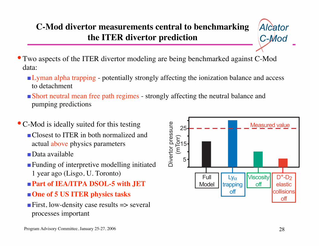
C-Mod divertor measurements central to benchmarkingthe ITER divertor prediction
• Two aspects of the ITER divertor modeling are being benchmarked against C-Moddata:
Lyman alpha trapping - potentially strongly affecting the ionization balance and accessto detachmentShort neutral mean free path regimes - strongly affecting the neutral balance andpumping predictions
• C-Mod is ideally suited for this testingClosest to ITER in both normalized andactual above physics parameters
Data available
Funding of interpretive modelling initiated1 year ago (Lisgo, U. Toronto)
Part of IEA/ITPA DSOL-5 with JETOne of 5 US ITER physics tasks
First, low-density case results => severalprocesses important
5
15
25
Div
ert
or
pre
ssu
re
(mTo
rr)
Full
Model
Lyαtrapping
off
Viscosity
off
D+-D2
elastic
collisions
off
Measured value

Program Advisory Committee, January 25-27, 2006 29
The newest modeled cases span a range of dimensionlessand dimensional parameters
• Three cases now have initial models
Low density - PDIV=25 mT (outer div. attached)
Med density - PDIV=75 mT (outer div. detached)
High density - PDIV=150 mT (x-point MARFE)
• The neutral densities span the ITER range =>
D2-D2 collisional mean free paths (1.3-7.8 mm),
small compared to the divertor volume
D+-D2 collisional mean free paths also 1-8 mm,
small compared to divertor fan
Photon absorption mean free paths ~ 1 mm
• each < relevant dimension => excellent test of
codes
• Next steps
Finish interpretive modelling
Move on to self-consistent predictive modelling
25
0
50
75
100
125
150
175
150 mTorr
425
75 mTorr
25 mTorr
FullModel
Lyαtrapping
off
Viscosityoff
D+-D2elastic
collisionsoff
Div
ert
or
pre
ssure
(m
To
rr)

Program Advisory Committee, January 25-27, 2006 30
Dust studies initiated
• Dust is studied for a number of reasonsSafety problems
Plasma impurities (plasma performance)
• Initial work concentrated on diagnosticsDust characterization during vacuum breaks incollaboration with INEL
Dust quantity and dynamics during shotsImage analysis
MIE scattering
• PlansContinued development of the above
Try to ascertain the origin of dust & how it affects the coreplasma
Visible image
Results of dustrecognition algorithim

Program Advisory Committee, January 25-27, 2006 31
Experiments in 2005 have resulted in an improved (andnovel) upper cryopump concept
Goal: pumping for core and edge studies that separates heat and particle handling functions• Experiments showed that the previous concept would have a high sensitivity to secondary
strike-point location (~x3 variation in pressure)• New ‘pumping slot’ concept
Less sensitive to strike-point locationProximity to upper null also improves heat-flux handling
• Status/PlansTiles and support hardware manufacturedCryopump fabrication & testing in next 3 months; Installation in summer 2006
In-Vessel Penning Gauge
Cryopumpbaffle
In-Vessel Penning Gauge
SIMULATEDCryopumpbaffle
Cryopump SimulationExperiments Performedin 2005 Campaign
Previous CryopumpConcept
Improved 'Pumping Slot'Concept - to be installedin 2006
Toroidal array of 30 pumping slotsbetween tiles

Program Advisory Committee, January 25-27, 2006 32
Tungsten tile development program underway
Goal: ITER relevant tungsten tile developmentand operational experience
Status• 12 tungsten rod tiles installed in C-Mod
No measurable W content in core
Tiles surviving at leading edges
• Design change from rods to lamellae (plates)Simpler, cheaper - currently ITER aim
1st tests at SandiaMechanical attachment failure
Design revised and new tests at JulichTZM bolt holds lamellae together
Tests successful for a range of heat loads
Material bought and design being finalizedfor a toroidal ring of tiles next break

Program Advisory Committee, January 25-27, 2006 33
C-Mod research well-aligned to ITPA high-priorityresearch areas
The C-Mod boundary physics program addresses a number of high priority ITPAissues including:
• Improve understanding of tritium retention & the processes that determine it.
Understanding D levels on tiles and tile sides for B and Mo
Understanding removal of D at low tile temperature
• Improve understanding of SOL plasma interaction with the main chamber.
Wall flux measurements (‘main chamber recycling’)
Impurity influx and screening studies
• Develop improved prescription of SOL perpendicular transport coefficients and
boundary conditions for input to BPX modelling.
Radial flux analysis - transport coefficients
Gradient scaling work (near SOL) connection to fluid turbulence theories
Dimensionless comparisons scalings of SOL characteristics across tokamaks
SOL flows and effect on core

Program Advisory Committee, January 25-27, 2006 34
C-Mod is actively involved in coordinated experimentsacross tokamaks & in support of ITER
• Our divertor/edge scientists seek out collaborations with other tokamaks in order to testideas or gain new information
• The collaborations are encouraged through the IEA/ITPA frameworkDSOL-3 ‘Study of radial transport’, B. Lipschultz organizer
DSOL-5 ‘Role of Lyman absorption in the divertor’, J. Terry, contributor
DSOL-4 ‘Comparison of disruption energy balance and heat flux profile’, D. Whyte, J.Terry, contributor
DSOL-11 ‘Disruption mitigation experiments’, D. Whyte organizer, R. Granetz, contributor
DSOL-13 ‘Deuterium co-deposition with C in gaps of plasma facing components B.Lipschultz, D. Whyte participants
DSOL-15 ‘Inter-machine comparison of blob characteristics’ J. Terry organizer
• The ITER team has requested that the US (C-Mod) advance the understanding of divertorradiation absorption through benchmarking codes - ITER-US subtask 3
Program Advisory Committee, January 25-27, 2006 35
• Our intent is to continue to make fundamental contributions with emphasis on thefollowing :
Steady state profile transport analysis to understand
Role of gradients in determining near SOL transport
Poloidal variations, machine scalings (to ITER), role of neutrals
Edge flows importance in affecting impurities and the core plasma
Turbulence studies
Turbulence relationship to large convective transport
Improved images/analyses/scalings/simulations & predictive capability
Continued H/D retention and removal studies
Develop separable divertor particle and heat control functions
Optimize high-Z first-wall and divertor for long-pulse & high heat flux operation
Understanding boronization and its erosion
Development of strategies to extend the boronization layer lifetime
Boundary Physics: Summary