c. · pdf fileto represent currently accepted design practices in north america ... design and...
TRANSCRIPT

C. TRAIL DESIGNER’S
TOOLBOX


C-i OXFORD COUNTY TRAILS MASTER PLAN
FINAL APPENDIX C – TRAIL DESIGNERS’ TOOLBOX | DECEMBER 2014
TABLE OF
CONTENTS
C.1 INTRODUCTION ................................................................................................................................ C-1
C.2 HOW TO USE THE DESIGN GUIDELINES ...................................................................................... C-1
C.3 CONSIDERATIONS WHEN DESIGNING TRAILS ............................................................................ C-2
C.3.1 Types of Users .................................................................................................................... C-2
C.3.2 General Design Parametres ................................................................................................ C-6
C.3.3 Types of User Trips ........................................................................................................... C-10
C.3.4 Accessibility ....................................................................................................................... C-11
C.3.5 Personal Security .............................................................................................................. C-12
C.3.6 Urban, Suburban and Rural Areas .................................................................................... C-14
C.4 TRAIL DESIGN ALTERNATIVES .................................................................................................... C-14
C.4.1 Off-road Routes ................................................................................................................. C-15
C.4.2 On-road Linkages .............................................................................................................. C-15
C.4.3 Routes Crossing 400 Series Highways at Interchanges ................................................... C-17
C.4.4 Surface Types & Alternatives ............................................................................................ C-17
C.4.5 Trail Lighting ...................................................................................................................... C-20
C.5 ADDITIONAL DESIGN CONSIDERATIONS ................................................................................... C-22
C.5.1 Trail Crossings ................................................................................................................... C-22

C-ii OXFORD COUNTY TRAILS MASTER PLAN FINAL APPENDIX C – TRAIL DESIGNERS’ TOOLBOX | DECEMBER 2014
C.5.2 Trail Structures .................................................................................................................. C-26
C.5.3 Trip End Facilities & Staging Areas ................................................................................... C-30
C.5.4 Closures and Rehabilitation ............................................................................................... C-33
C.6 SIGNING THE TRAIL NETWORK .................................................................................................... C-34

C-1 OXFORD COUNTY TRAILS MASTER PLAN FINAL APPENDIX C – TRAILS DESIGNERS’ TOOLBOX | DECEMBER 2014
C.1 INTRODUCTION
The guidelines prepared for the Oxford County Trails Master
Plan should be treated as a reference for the development
and construction of the trail network including primarily off-
road trail connections as well as some key on-road linkages.
Although they are meant to provide guidance for the range of
conditions typically encountered in a municipal-wide network,
they are not intended to address every condition encountered.
As a guidance document this appendix is not meant to be
prescriptive nor is it intended that these replace “sound
engineering judgement”. The intent is to have regard to the
individual guidelines when implementing facilities at specific
locations to arrive at the most appropriate solution.
In some cases an interim solution may be appropriate where
the desired long-term solution cannot be achieved in the short
or mid-term, provided that the interim solution meets users’
needs and safety considerations.
When using these guidelines it may also be appropriate to
consult additional guidelines on a case-by-case basis. Other
useful references include but are not limited to:
The County of Oxford Transportation Master Plan Study–
Section 5.0 – Cycling
Ontario Traffic Manual (OTM) Book 18 (Cycling Facilities)
OTM Book 15 (Pedestrians)
Transportation Association of Canada Bikeway Traffic
Control Guidelines
Accessibility for Ontarians with Disabilities Act, 2005,
Amending O. Reg. 191/11. Part IV.1 Design of Public
Spaces Standards (Accessibility Standards for the Built
Environment)
C.2 HOW TO USE THE DESIGN GUIDELINES
C.2.1 THE PURPOSE
The purpose of these guidelines is to assist County and local
municipal staff in making informed decisions about off-road
trail and on-road cycling facility design.
C.2.2 HOW TO USE THE GUIDELINES
The guidelines provide general information on a range of trail
user groups including but not limited to cyclists, pedestrians,
cross county skiers, equestrians, etc. Where appropriate,
summary tables are provided which highlight recommended
design treatments and / or considerations when addressing
key features associated with various on and off-road trail and
cycling facilities proposed in the Oxford County Trails Master
Plan. The information included in these guidelines is thought
to represent currently accepted design practices in North
America, and incorporates ongoing research and experience
by the consulting team and other professionals involved with
trail and cycling facility design.
Guidelines:
C-1: Adopt the trail design guidelines presented in Appendix
C of the Oxford County Trails Master Plan as the basis for the
design of trails County-wide.
C-2: County staff should distribute the trail design guidelines
to trail designers and builders e.g. the Oxford Trails Council
and conservation authorities to encourage consistent trail
design and implementation County-wide.
C-3: County staff should supplement the Master Plan design
guidelines with additional resources including but not limited
to the Ontario Traffic Manual (OTM) Books 18 and 15 and
other best practices as they emerge.

C-2 OXFORD COUNTY TRAILS MASTER PLAN FINAL APPENDIX C – TRAILS DESIGNERS’ TOOLBOX | DECEMBER 2014
C.3 CONSIDERATIONS WHEN DESIGNING TRAILS
Many elements of trail design need to be considered when a
trail is being developed, and the elements vary depending on
location. Some of these include:
New construction versus upgrading existing trails;
Trail location;
Context (urban, rural or suburban);
Level of separation (on vs. off-road);
Width;
Surface type;
User groups;
Level of use;
Seasonal versus year round use;
Gradient;
Accessibility;
Degree of difficulty;
Length;
Ownership;
Sustainability and ability to maintain;
Access points;
Transition points / linkages;
Context sensitive conditions;
Road crossings; and
Signage.
C.3.1 TYPES OF USERS
Trail users vary in age and level of physical ability. They have
their own sense of what the trail experience should be, which
in part depends on the use they are interested in or what user
group they consider themselves to be a part of. A “one size
fits all” design approach does not apply to trails and it is
important to try and match the trail type and design with the
type of experience that is desired, while at the same time
achieving a predictable and recognizable quality and
consistency in the design. This will enhance the experience,
enjoyment and safety for a range of trail users and add value
to the communities the trail network travels through.
It is always important to consider the characteristics and
preferences of potential user groups. In Oxford County the
user groups that have been considered and are expected to
be the primary users of the trail system are pedestrians and
cyclists. However, other groups such as cross county skiers,
snowshoers and equestrians have also been considered and
are expected to be seasonal users of the system.
It is acknowledged that other user groups such as
Equestrians, All-Terrain Vehicle (ATV) operators and
snowmobilers currently own, operate, maintain and use some
of the trails found throughout the County. Motorized trail users
have not been considered within the Oxford County Trails
Master Plan, though there may be some cases where trails
intended for non-motorized users overlap with existing trails
intended for motorized recreational users. Although the cases
may be infrequent, adequate and proper signage related to
safe interactions should be implemented. This is also the case
for users that may surround the trail systems including the
potential for in-season hunters.
The following is a brief description of the primary user groups,
how they typically use the trails and design parameters which
should be considered when proceeding with trail design. Trans Canada Trail in Tillsonburg, ON Source: MMM Group

C-3 OXFORD COUNTY TRAILS MASTER PLAN FINAL APPENDIX C – TRAILS DESIGNERS’ TOOLBOX | DECEMBER 2014
Pedestrians be
For the Oxford County Trails Master Plan “pedestrians”
include walkers, hikers, joggers and runners. Table C.1
provides additional design considerations for the anticipated
pedestrian user groups.
.
.
Table C.1 - Pedestrian User Groups
Walkers
Definition:
Walkers represent a wide range of interests and motives such as leisure, relaxation, socializing, exploring,
making contact with nature, meditation, fitness, or dog walking. It is also important to consider pedestrians
who walk for utilitarian or transportation purposes. This group is typically community-focused and engage in
trips focusing on shopping and errands and walking to work and school.
Utilitarian Walkers are typically found within more urban areas and tend to use sidewalks, parking lots and
plazas as well as trails where they are convenient, well designed and properly maintained. In many cases,
trails provide a convenient “short cut” to traveling the sidewalk network to get to their destination.
Where no sidewalks are provided and there are no shoulders (in urban and/or rural areas), pedestrians
should walk on the edge of the roadway facing oncoming traffic consistent with the Ontario Highway Traffic
Act. Signs warning motorists of pedestrians ahead are recommended in high use locations.
Hikers
Definition:
Hikers are often considered the elite of the recreational walking group and may challenge themselves to
cover long distances and be willing to walk on sections of rural roadway shoulder considered less safe or
less interesting by the majority of leisure walkers.
This group typically engages in day trips that may range between 5 and 30 km in length, may be more
keenly interested in natural features, are often more adept at map reading, are more self-sufficient than
leisure walkers, may expect fewer amenities and are often attracted to challenging terrain and rural areas.
Trail planners should assume that there may be hikers even in remote or highway environments despite the
fact that the frequency may be very low.
Joggers / Runners
Definition:
Although the primary motivation for joggers and runners may be fitness, they may share more in terms of
profile characteristics with distance hikers than they do with leisure walkers.
This group typically is accomplishment oriented, enjoy trails at higher speed for distances between 3 and 15
km or more and avoid hard surfaces such as asphalt and concrete and prefer to run on granular, natural
(earth) and turf surfaces as they provide more cushioning effect.
Ninety-five percent of all pedestrian trips are less than
2.5km in length, though it is reasonable to expect that
some walkers whose trips are motivated by exercise /
health / fitness might make trips that are between 5 and
10km in length.

C-4 OXFORD COUNTY TRAILS MASTER PLAN FINAL APPENDIX C – TRAILS DESIGNERS’ TOOLBOX | DECEMBER 2014
Cyclists be
Some bicycles, including the “mountain” or “hybrid” can travel
easily over stone dust and gravel surfaces, whereas,
traditional narrow-tired touring and racing bicycles require
very well compacted granular surfaces or hard surface
pavements such as asphalt.
Points to consider when designing for cyclists:
The mechanical efficiency of the bicycle allows users of
all ages to travel greater distances at a higher rate of
speed than pedestrians.
Distances covered vary widely from a few kilometres to
well over a hundred depending on the fitness level and
motivation of the individual cyclist.
Cyclists have the right to access the public roadway
system, with the exception of the 400 series and major
provincial highways or where prohibited by law.
Some cyclists feel unsafe sharing the road with
automobiles and do not have the desire or skill level to
ride in traffic.
Some cyclists tend to prefer off-road trails, shared with
pedestrians as these facilities offer the less experienced
and less confident cyclist a more comfortable
environment.
Cyclists that travel longer are more likely to focus a
significant portion of their route on the roadway network,
and often seek out quieter, scenic routes over busier
roads even if the pavement quality is lower than on
busier roads.
The average travel speed for a cyclist on a trail is in the range
of 15-20 km/h and 18-30+ km/h on a road, with speeds in
excess of 50 km/h. while traveling downhill on roads and
some hard surface trails. Where excessive speed is a
potential issue on trails, speed limits and warnings should be
posted to discourage fast riding and aggressive behaviour.
Cyclists other than young children should be discouraged
from cycling on sidewalks because of potential conflicts with
pedestrians and potentially dangerous intersections with
intersecting public road, private driveways and entrances.
Many municipalities have prohibited sidewalk cycling through
local by-law, however, many municipalities permit sidewalks
cycling for children learning to ride.
When using roads, cyclists generally travel 0.5 – 1.0m
from the curb or other obstruction because of the
possibility of accumulated debris, uneven
longitudinal joints, catch basins, steep cross slopes,
or concern over hitting a pedal on the curb or
handlebar on vertical obstacles. However, when
cyclists use or cross a public roadway they are
considered vehicles by law and are expected to follow
the same traffic laws as motorized vehicles.
Cycling on Off-road Trails Source: blog.hembrowcyclingholidays.com
C-5 OXFORD COUNTY TRAILS MASTER PLAN FINAL APPENDIX C – TRAILS DESIGNERS’ TOOLBOX | DECEMBER 2014
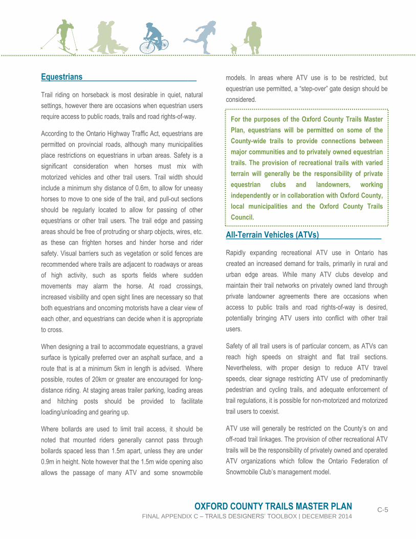
Equestrians be
Trail riding on horseback is most desirable in quiet, natural
settings, however there are occasions when equestrian users
require access to public roads, trails and road rights-of-way.
According to the Ontario Highway Traffic Act, equestrians are
permitted on provincial roads, although many municipalities
place restrictions on equestrians in urban areas. Safety is a
significant consideration when horses must mix with
motorized vehicles and other trail users. Trail width should
include a minimum shy distance of 0.6m, to allow for uneasy
horses to move to one side of the trail, and pull-out sections
should be regularly located to allow for passing of other
equestrians or other trail users. The trail edge and passing
areas should be free of protruding or sharp objects, wires, etc.
as these can frighten horses and hinder horse and rider
safety. Visual barriers such as vegetation or solid fences are
recommended where trails are adjacent to roadways or areas
of high activity, such as sports fields where sudden
movements may alarm the horse. At road crossings,
increased visibility and open sight lines are necessary so that
both equestrians and oncoming motorists have a clear view of
each other, and equestrians can decide when it is appropriate
to cross.
When designing a trail to accommodate equestrians, a gravel
surface is typically preferred over an asphalt surface, and a
route that is at a minimum 5km in length is advised. Where
possible, routes of 20km or greater are encouraged for long-
distance riding. At staging areas trailer parking, loading areas
and hitching posts should be provided to facilitate
loading/unloading and gearing up.
Where bollards are used to limit trail access, it should be
noted that mounted riders generally cannot pass through
bollards spaced less than 1.5m apart, unless they are under
0.9m in height. Note however that the 1.5m wide opening also
allows the passage of many ATV and some snowmobile
models. In areas where ATV use is to be restricted, but
equestrian use permitted, a “step-over” gate design should be
considered.
All-Terrain Vehicles (ATVs) be
Rapidly expanding recreational ATV use in Ontario has
created an increased demand for trails, primarily in rural and
urban edge areas. While many ATV clubs develop and
maintain their trail networks on privately owned land through
private landowner agreements there are occasions when
access to public trails and road rights-of-way is desired,
potentially bringing ATV users into conflict with other trail
users.
Safety of all trail users is of particular concern, as ATVs can
reach high speeds on straight and flat trail sections.
Nevertheless, with proper design to reduce ATV travel
speeds, clear signage restricting ATV use of predominantly
pedestrian and cycling trails, and adequate enforcement of
trail regulations, it is possible for non-motorized and motorized
trail users to coexist.
ATV use will generally be restricted on the County’s on and
off-road trail linkages. The provision of other recreational ATV
trails will be the responsibility of privately owned and operated
ATV organizations which follow the Ontario Federation of
Snowmobile Club’s management model.
For the purposes of the Oxford County Trails Master
Plan, equestrians will be permitted on some of the
County-wide trails to provide connections between
major communities and to privately owned equestrian
trails. The provision of recreational trails with varied
terrain will generally be the responsibility of private
equestrian clubs and landowners, working
independently or in collaboration with Oxford County,
local municipalities and the Oxford County Trails
Council.

C-6 OXFORD COUNTY TRAILS MASTER PLAN FINAL APPENDIX C – TRAILS DESIGNERS’ TOOLBOX | DECEMBER 2014
Speed limits should be posted along all trails where ATV use
is permitted (the County’s existing Gold Trails). Stopping sight
distance is the distance required to for the trail user to come
to a full controlled stop upon spotting an obstacle. It is a
function of the user’s perception and reaction time. At 40km/h,
an ATV rider has a sight stopping distance of approximately
34m, thus all potential hazards, including trail intersections,
should be signed at least 45m in advance. Slower speeds can
be encouraged by including curves, grade changes and trail
narrowing, although these design features should be
accompanied by signage indicating that the ATV rider should
reduce speed.
In these shared use trail locations the trail surface should be
hard and smooth, with no rocks or roots protruding more than
7.5cm, no depressions larger than 0.6m wide or 15cm deep,
and trail clear width should be a minimum of 0.6m beyond the
edge of the trail bed. To allow safe passing of other trail users,
pull-out sections of at least 8m in length should be added at
regular intervals along the trail.
An additional characteristic of ATVs to consider when
designing shared trails is weight of the vehicle. The combined
weight of an ATV and rider can exceed 350kg, which has the
potential to result in significant wear on the trail bed and
surface. In abandoned rail corridors where the rail bed is in
place, the trail bed can be assumed to be capable of
supporting the weight of an ATV, however trail surfaces
should be sufficiently stabilized to resist deformation and
erosion, and they should be inspected and maintained
regularly to repair potholes and ruts that may result from ATV
use. Similar design guidelines should be applied to
snowmobile use in winter, on trails where ATV use is
permitted.
Hunting should not be permitted on trails or from trails,
although hunters may be using parts of the trail system to
access hunting areas at certain times of the year. It should
also be noted that hunting may be permitted at certain times
of the year in some County forests where trails are also
located. Where hunters are using trails to access hunting
areas, firearms must not be loaded. Trailhead signage should
clearly communicate hunting prohibitions / seasonal
permissions and advise trail users that hunters may be
present on lands surrounding some trails at certain times of
the year. Rules related to hunting must be strictly enforced to
ensure safety for all users.
C.3.2 GENERAL DESIGN PARAMETRES
Cyclists require a certain amount of space to maintain stability
when operating a bicycle. Figure C.1 illustrates the typical
Cyclist Operating Space. Generally an operating width of
1.2m to 1.5m is sufficient to accommodate forward movement
by most cyclists, however there can be considerable
difference in the physical dimensions and operating space
requirements depending a cyclist’s age and skill level. Cyclists
do not travel in a straight line and manoeuvring space is
needed to allow for side-to-side movements during operation.
ATV and Snowmobile Use of Trails Source: gunflint-trail.com

C-7 OXFORD COUNTY TRAILS MASTER PLAN FINAL APPENDIX C – TRAILS DESIGNERS’ TOOLBOX | DECEMBER 2014
The 1.2m to 1.5m operating width is greater than the physical
width momentarily occupied by a cyclist in order to
accommodate natural side-to-side movement that varies with
speed, wind, and cyclist proficiency. The operating height of
2.5 metres can generally accommodate an average adult
cyclist standing upright on the pedals of a bicycle.
Careful consideration should be given to the physical,
aesthetic and environmental requirements for each multi-use
trail type. In many instances physical design criteria related to
operating space, design speed, alignment and clear zones are
often governed by the needs of the fastest, most common
user group on the majority of the trails, that being the cyclist.
Therefore, many of the physical design criteria outlined in the
following sections are recommended for to cycling. This is not
to say that all multi-use trails need to be designed to meet the
requirements for cyclists; however, when multi-use trails are
being designed it is prudent to use design parameters for the
cyclist. When considering single or specialty uses where part
of the trail experience involves maneuvering through
challenging conditions, such as BMX or mountain cycling, the
parameters outlined below may not apply. In these instances,
designers should consult directly with the user group and/or
design manuals that are specific for that use. Trail user
operating space is a measurement of the horizontal space
that the user requires. In the case of in-line skating and
cycling, the space includes room required for side to side
body motion used to maintain balance and generate
momentum. Table C.2 outlines minimum and preferred
operating space for different uses.
Table C.2 – Minimum and Preferred Operating Space
Operating Condition by
Trail User Type
Minimum (metres)
Preferred (metres)
One way travel (one wheelchair
user) 1.2 1.5
One way travel (two pedestrians)
1.5 2.0
One way travel (one cyclist)
1.2
(in constrained locations)
1.5+
One way travel (one in-line skater)
2.3 3.0
One way travel (one equestrian)
1.7-2.4 4.3-5.5
Two way travel (two cyclists)
3.0 3.0+
Two way travel (two wheelchair
users) 3.0 3.0+
Figure C.1 – Typical Cyclist Operating Space
Source: Based on information from the AASHTO Guide for the
Planning, Design and Operation of Bicycle Facilities, 2012
Typical
0.9
-

C-8 OXFORD COUNTY TRAILS MASTER PLAN FINAL APPENDIX C – TRAILS DESIGNERS’ TOOLBOX | DECEMBER 2014
Horizontal clear distance is the space beside the trail bed that
should be kept clear of protruding objects. Vertical clear
distance is the space above the head of the user while using
the trail (i.e. walking or mounted on their bicycle). Table C.3
provides minimum and preferred horizontal and vertical clear
distance.
Table C.3 – Horizontal and Vertical Clear Distance
Clearance Condition Minimum (metres)
Preferred (metres)
Horizontal clearance to stationary objects
0.3 1.0
Vertical clearance to stationary objects
2.5 3.0
Slope refers to both the measured fall over a given distance
along the centerline (referred to as longitudinal slope) and
perpendicular to the centerline (referred to as cross slope).
Cross slope can be configured so that all runoff is directed to
one side of the trail, or so that there is centre crown and runoff
is shed to either side of the trail. Table C.4 provides guidance
regarding longitudinal and cross slope.
Table C.4 – Longitudinal and Cross Slope
Longitudinal Grade or Slope
0% to 3% Preferred
5%-10%
Provide additional trail width where trail
segments are greater than 100m in length
Introduce level rest areas every 100 to
150m of horizontal distance
Consider design strategies such as
switchbacks when slopes approach 10%
Install signing to alert users of upcoming
steep grades
Avoid grades over 5% for off road trails.
Where steeper slopes are necessary “trail
hardening” should be considered
Note: 10:1 (horizontal distance or run:
vertical distance or rise), or 10% is the
Table C.4 – Longitudinal and Cross Slope
maximum permissible slope for meeting
accessibility standards. Level landings or
rest areas are required at regular intervals.
10% to 15%
Consider the use of structures such as
steps, step and ramp combinations, or
stairways
Consider locating the trail elsewhere
15% or over
15% represents the maximum possible
longitudinal slope for a sustainable trail
surface. Where slopes approach or
exceed 15% significant washouts become
an ongoing issue.
Structures such as steps, step and ramp
combinations and stairways should be
employed. Otherwise, an alternative
location for the pathway should be sought.
Cross Slope
2%
Minimal, acceptable on hard surfaced
trails, may not provide adequate drainage
on granular surfaced trails
2 to 4% Preferred range for both hard and granular
surfaced trails
Greater than 5%
Avoid wherever possible as excessive
cross slopes can be difficult and potentially
dangerous for some levels of physical
ability and certain user groups as they can
result in difficulty maintaining balance,
especially among user groups with a high
centre of gravity.
Design speed is used to determine trail width, minimum curve
radius, horizontal alignment and banking or super elevation to
ensure that trail users have adequate space and time to safely
approach and navigate sharper curves along the trail. The
design speed for recreational cyclists is generally considered
adequate for all self-propelled trail users including
pedestrians, in-line skaters, skateboarders, scooter users and
those using mobility devices such as wheelchairs.

C-9 OXFORD COUNTY TRAILS MASTER PLAN FINAL APPENDIX C – TRAILS DESIGNERS’ TOOLBOX | DECEMBER 2014
The average recreational cyclist can maintain speeds of up to
18-25 km/h on some multi-use pathways. For granular
surfaced off-road multi-use pathways or trails, a design speed
in the area of 25 km/h is usually adequate, whereas a design
speed of 40 km/h should be considered for hard surfaced
multi-use pathways and trails on steeper descents. Cautionary
signing should be used to warn of upcoming steep grades and
sharp curves.
Cyclists are the critical user group when designing off-road
multi-use trails for self-propelled users as they have the
highest average travel speed. The minimum radius of a curve
on an off-road cycling facility depends on the bicycle speed
and super-elevation. The AASHTO Guide for the
Development of Bicycle Facilities, published in 2012
recommends that the general design speed should be 29km/h
for multi-use trails where cycling is the highest speed user
group.
Based on research, 29km/h represents the 85th percentile for
bicycle speed on granular surfaced trails. The slightly lower
design speed will allow for slightly smaller curve radii and
potentially less construction impact as compared to multi-use
pathways and trails requiring larger radii. Refer to Table C.5
for suggested centerline radii for a range of design speeds
and super elevation rates.
Table C.5 – Suggested Pathways and Trail Radii Based on Travel Speeds
Design Speed (km / h)
Suggested Radius (m) where super elevation =
0.02 m/m
Suggested Radius (m) where super elevation =
0.05 m / m
25 15 14
30 24 21
35 33 30
40 47 42
45 64 57
When horizontal curves are sharp (i.e. a very small radius),
facility widening should be considered to compensate for the
tendency of cyclists to track toward the outside of the curve.
Table C.6 provides additional widening requirements for
curves on multi-use pathways and trails where the radii are
less than the recommended minimum for the design speed
selected.
Table C.6 – Additional Trail Widening on the Outside of the Curve
Radius (m) Additional Widening (m)
0 - 7.5 1.2
7.5 - 15 0.9
15 - 22.5 0.6
22.5 - 30 0.3
Stopping sight distances for off-road multi-use trails are
typically governed by the distance required for cyclists since
pedestrians and other trail users can typically stop more
quickly than cyclists, regardless of the trail configuration.
Guideline(s):
C-4: The County, local municipalities and representatives
from the Oxford Trails Council should refer to the minimum
and preferred trail user operating space widths identified in
Table C.2 when developing or reviewing multi-use trail
design concepts.
C-5: The County, local municipalities and representatives
from the Oxford Trails Council should refer to the minimum
and preferred horizontal and vertical clear distance identified
in Table C.3 when developing or reviewing multi-use trail
design concepts.

C-10 OXFORD COUNTY TRAILS MASTER PLAN FINAL APPENDIX C – TRAILS DESIGNERS’ TOOLBOX | DECEMBER 2014
C-6: The County, local municipalities and representatives
from the Oxford Trails Council should refer to the
longitudinal and cross slope guidelines identified in Table
C.4 when developing or reviewing multi-use trail design
concepts.
C-7: County, local municipalities and representatives from
the Oxford Trails Council should consider the suggested trail
curve radii and additional trail widening dimensions identified
in Table C.5 when developing and reviewing multi-use trail
design concepts.
C.3.3 TYPES OF USER TRIPS
Trail users can also be defined by their trip purpose and
intent. Trip purpose can be divided into the following three (3)
categories – utilitarian, recreational and touring. Additional
details regarding each of these groups are presented in Table
C.7.
Table C.7 - Trail User Trip Purpose
Utilitarian
Definition:
Those who use cycling or walking as their day to day mode of transportation to get to and from work, school,
errands, etc.
Utilitarian trail users often use the on and off-road linkages that make up the trails network year-round in all
weather conditions as opposed to those roads which do not make up part of the designated network. In
some cases they may choose to use public transit or other modes of transportation during the winter season.
Typically utilitarian users have good mobility skills and are cognisant of the “rules of the road”.
Recreational
Definition:
These pedestrians and cyclists will typically use the network for fitness or leisure purposes.
Trips are typically used for travel on weekends as opposed to weekdays and will consist of trips to and from
destinations of cultural or natural significance including off-road recreational trails.
They will typically use the off-road or secondary connections as part of the overall network.
Touring
Definition:
These pedestrians, cyclists and other seasonal trail users use trails as a means of exploring areas of
significance long-distances from their point of origin.
Trips can vary from full day excursions to multi-day excursions. They may plan their trips in advance and are
willing to spend money for accommodation and food at their destination point. In some cases they travel in
groups.
C-11 OXFORD COUNTY TRAILS MASTER PLAN FINAL APPENDIX C – TRAILS DESIGNERS’ TOOLBOX | DECEMBER 2014
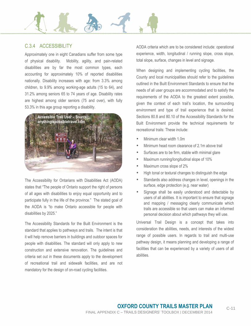
C.3.4 ACCESSIBILITY
Approximately one in eight Canadians suffer from some type
of physical disability. Mobility, agility, and pain-related
disabilities are by far the most common types, each
accounting for approximately 10% of reported disabilities
nationally. Disability increases with age: from 3.3% among
children, to 9.9% among working-age adults (15 to 64), and
31.2% among seniors 65 to 74 years of age. Disability rates
are highest among older seniors (75 and over), with fully
53.3% in this age group reporting a disability.
The Accessibility for Ontarians with Disabilities Act (AODA)
states that “The people of Ontario support the right of persons
of all ages with disabilities to enjoy equal opportunity and to
participate fully in the life of the province.” The stated goal of
the AODA is “to make Ontario accessible for people with
disabilities by 2025.”
The Accessibility Standards for the Built Environment is the
standard that applies to pathways and trails. The intent is that
it will help remove barriers in buildings and outdoor spaces for
people with disabilities. The standard will only apply to new
construction and extensive renovation. The guidelines and
criteria set out in these documents apply to the development
of recreational trail and sidewalk facilities, and are not
mandatory for the design of on-road cycling facilities.
AODA criteria which are to be considered include: operational
experience, width, longitudinal / running slope, cross slope,
total slope, surface, changes in level and signage.
When designing and implementing cycling facilities, the
County and local municipalities should refer to the guidelines
outlined in the Built Environment Standards to ensure that the
needs of all user groups are accommodated and to satisfy the
requirements of the AODA to the greatest extent possible,
given the context of each trail’s location, the surrounding
environment and type of trail experience that is desired.
Sections 80.8 and 80.10 of the Accessibility Standards for the
Built Environment provide the technical requirements for
recreational trails: These include:
Minimum clear width 1.0m
Minimum head room clearance of 2.1m above trail
Surfaces are to be firm, stable with minimal glare
Maximum running/longitudinal slope of 10%
Maximum cross slope of 2%
High tonal or textural changes to distinguish the edge
Standards also address changes in level, openings in the
surface, edge protection (e.g. near water)
Signage shall be easily understood and detectable by
users of all abilities. It is important to ensure that signage
and mapping / messaging clearly communicate which
trails are accessible so that users can make an informed
personal decision about which pathways they will use.
Universal Trail Design is a concept that takes into
consideration the abilities, needs, and interests of the widest
range of possible users. In regards to trail and multi-use
pathway design, it means planning and developing a range of
facilities that can be experienced by a variety of users of all
abilities.
Accessible Trail User – Source: anythingispossibletravel.com

C-12 OXFORD COUNTY TRAILS MASTER PLAN FINAL APPENDIX C – TRAILS DESIGNERS’ TOOLBOX | DECEMBER 2014
Principles of universal trail design can be summarized as
follows:
Equitable use: provide opportunity for trail users to
access, share and experience the same sections of trail
rather than providing separate facilities;
Flexibility in use: provide different options for trail users in
order to accommodate a variety of experiences and allow
choice;
Simple, intuitive and perceptible information: whether
conveying trail information through signage, maps or a
web site, communicate using simple, straightforward
forms and formats with easy to understand graphics
and/or text;
Tolerance for error: design trails and information systems
so as to minimize exposure to hazards, and indicate to
users any potential risks or challenges that may be
encountered;
Low physical effort: trails may provide for challenge but
should not exceed the abilities of the intended users;
where appropriate, rest areas should be provided; and
Size and space for approach and use: trails and
amenities should provide for easy access, comfort and
ease in their usage.
Ontario’s Best Trails – (2006) provides an in depth discussion
of the application of Universal Design principles and their
application.
Where possible and practical trails should be designed to be
accessible to all levels of ability. It must be recognized, that
not all trails and multi-use pathways throughout the system
can meet all accessibility requirements. Steep slopes are one
of the most significant barriers for those with physical
disabilities. Designing trails to be below the threshold (5%
longitudinal slope) for universal access will not only overcome
this significant barrier but it will help to reduce the potential for
erosion of the trail surface. The following are some additional
considerations for making existing and new trails accessible:
Designers should use the most current standards;
Where the trail requires an accessibility solution that is
above and beyond what is normally encountered, a
representative of the local accessibility advisory
committee should be consulted early on in the process to
determine if it is practical and desirable to design the
specific trail to be accessible;
Where it has been determined that accessibility is
feasible, the accessibility representative should be
consulted during the detailed design process to ensure
that the design is appropriate; and
Work collaboratively with the local accessibility advisory
committee to consider developing signage/content to
clearly indicate trail accessibility conditions, which allow
users with mobility-assisted devices to make an informed
decision about using a particular trail.
Guideline(s):
C-8: Every effort should be made to ensure that primary
trails meet or exceed minimum accessibility requirements.
Secondary multi-use trails will be designed to meet minimum
accessibility requirements where feasible and practical.
C-9: Signage and maps should be designed to
communicate which pathways and trails meet minimum
accessibility requirements so that users can make their own
decisions in advance about using the route.
C.3.5 PERSONAL SECURITY
To the extent that it is possible trail routes should be designed
to allow users to feel comfortable, safe, and secure. Although
personal safety can be an issue for all, women, the elderly,
children, are among the most vulnerable groups. Principles of
Crime Prevention Through Environmental Design (CPTED)
should be considered and applied to help address security
issues concerning trail use, particularly in locations where
trails are lightly used, isolated or in areas where security
problems have occurred in the past. The four main underlying
principles of CPTED are presented in Table C.8.

C-13 OXFORD COUNTY TRAILS MASTER PLAN FINAL APPENDIX C – TRAILS DESIGNERS’ TOOLBOX | DECEMBER 2014
Some specific trail design strategies that other jurisdictions
have employed include:
Providing good visibility for other by having routes pass
through well-used public spaces.
Providing the ability to find and obtain help using signage
that tells users where they are along the trail system.
Providing signs near entrances to isolated areas to
inform users and suggest alternative routes.
Providing escape routes from isolated areas at regular
intervals.
Maintaining sight lines and sight distances that are
appropriately open to allow good visibility by users.
Providing trailhead parking in highlight visible areas.
Minimizing routes close to features that create hiding
places such as breaks in building facades, stairwells,
dense shrubs and fences.
Designing underpasses and bridges so that users can
see the end of the feature as well as the areas beyond.
Table C.8 – Guiding Principles of CPTED for trail Design
Natural Access Control
Deters access to a target and creates a perception of risk to the offender.
Natural Surveillance
The placement of physical features and / or activities and people that maximizes natural visibility or observation.
Table C.8 – Guiding Principles of CPTED for trail Design
Territorial Reinforcement
Defines clear borders of controlled space from public to semi-private to private, so that users of an area develop a sense of ownership.
Maintenance
Allows for the continued use of space for its intended purpose.
Guideline(s):
C-10: When implementing the trails network, the underlying
principles of CPTED should be considered including natural
access control, natural surveillance, territorial reinforcement
and maintenance.
C-11: Properly located entrances, exists, fencing,
landscaping and lighting should direct both foot and
automobile traffic in ways that discourage crime.
Credit: CPTED Ontario
www.cptedontario.ca
Credit: CPTED Ontario www.cptedontario.ca
Credit: CPTED Ontario www.cptedontario.ca
Credit: Friends of King Gap www.friendsofkingsgap.org

C-14 OXFORD COUNTY TRAILS MASTER PLAN FINAL APPENDIX C – TRAILS DESIGNERS’ TOOLBOX | DECEMBER 2014
C.3.6 URBAN, SUBURBAN AND RURAL
AREAS
Typically urban / suburban users live closer to their
destinations than rural users. As such they are more likely to
make short trips and utilitarian / commuter trips. Urban will
generally have a higher order and density of infrastructure
than rural systems due to the higher density of users.
The application of bike lanes, paved shoulders, signed routes,
multi-use trails in the road right-of-way should be considered
for those routes found in the County’s and local municipal
urban and suburban areas. Routes in rural areas may include
paved shoulders, fewer designated routes, some linear off-
road trails (e.g. trails within abandoned railway or utility
corridors), and destination trails at conservation areas.
C.4 TRAIL DESIGN ALTERNATIVES
The trail network for Oxford County is divided into three main
categories: on-road facilities, multi-use trails within active road
ROW and multi-use trails outside of active road ROWs. Table
C.9 provides a general description of each
Table C.9 – General Design Categories
Multi-use Trail within an Active Road Right-of-way
Multi-use trails within active road rights-of-way (also referred to as a boulevard multi-use trail or Active Transportation Pathway) is a type of on-road facility that is within the roadway right-of-way but is physically separated from motor vehicle traffic where possible by a buffer.
Table C.9 – General Design Categories
Multi-use Trail outside of an Active Road Right-of-Way
These include trails of varying width, alignment and surface type that are located through conservation areas, public open spaces, valleys and parklands, as well as linear corridors such as abandoned railway lines, unopened road allowances and utility corridors.
On-Road Linkages
“On-road facility” refers to facilities within the roadway right-of-way that are located on or along an existing road and may be incorporated into the existing or future street network.
Source: Flickr – John Luton
Source: doorsopenoxford.ca
Source: MMM Group

C-15 OXFORD COUNTY TRAILS MASTER PLAN FINAL APPENDIX C – TRAILS DESIGNERS’ TOOLBOX | DECEMBER 2014
C.4.1 OFF-ROAD ROUTES
There are a range of off-road trail types which could be
considered for implementation as part of the Oxford County
Trails Network. The selection of the preferred design concept
should be confirmed by County and local municipal staff
based on a detailed assessment of existing characteristics
and natural surroundings.
The design concepts and guidelines prepared for Oxford
County are intended to be used by County staff as well as
those responsible for the design and implementation of trail
facilities throughout the County including but not limited to the
applicable conservation authorities, representatives from the
Oxford County Trails Council, local municipalities as well as
private land owners. The following trail design concepts
should be considered as the County moves forward with the
implementation of the master plan as well as the design and
development of trail facilities.
Each of the design concepts includes a description of its
definition, the user groups that are accommodated on the trail,
the types of materials which could be used to design the trails
as well as some other design consideration.
Figures C.2 – C.24 illustrate the different trail design
concepts that are proposed for consideration by Oxford
County. Additional descriptions / details regarding some of the
design concepts are provided later in the appendix.
C.4.2 ON-ROAD LINKAGES
One of the primary objectives of the County’s Trails Master
Plan is to develop a trail system that is off-road wherever
possible. However, in some cases this will not be possible and
on-road connections will need to be implemented. Typically,
this is the case in the rural areas of the County where long
distance connections will need to be made to link key off-road
trail systems.
This may also be the case in urban and suburban areas in
older residential neighbourhoods where public space is
confined to road rights-of-way and centralized park lands.
Where public land (other than the road right-of-way) is not
available and access agreement for trails on private lands are
not feasible, it is necessary to provide connecting links using
the road network. Where this is the case, pedestrians are
expected to use the sidewalk network in urban areas and road
shoulders in rural areas. Cyclists are expected to use on-road
facilities of multi-use / active transportation pathways in place
of a sidewalk.
As mentioned above, for those on-road linkages found within
the County’s trails network, County and local municipal staff
are encouraged to use the County’s Transportation Master
Plan – Cycling Component, OTM Book 18 and 15 as well as
the TAC Bikeway Traffic Control Guidelines (2012) to evaluate
and confirm the most appropriate cycling facility type.
OTM Book 18 sets out a facility selection process that can
assist staff and those responsible for the design and
implementation of on-road trail facilities. The facility selection
process provides a consistent framework that is easy to apply,
technically based (was developed based on current research
and knowledge of facility type selection), and allows flexibility
to account for the differences in physical and operational
characteristics from one site to another.
The selection tool does not tell designers when and when not
to provide a certain facility type but rather sets out a process
for selecting an appropriate facility type given the context and
readily available data.

C-16 OXFORD COUNTY TRAILS MASTER PLAN FINAL APPENDIX C – TRAILS DESIGNERS’ TOOLBOX | DECEMBER 2014
In Oxford County, a number of options exist for on-road
cycling routes including but not limited to signed bicycle
routes, edgelines, bike lanes and paved shoulders. In addition
to the commonly encountered situations where standard
design guidelines and treatments can be applied, there are
other situations where the proper design requires a more
context sensitive solution where more innovative techniques
need to be employed by a design specialist who is well versed
in emerging trends and best practices.
The graphics included on page C-25 illustrate some of the
proposed on-road cycling facility types which are proposed for
the County to consider and are consistent with the OTM Book
18 guidelines and standards.
Signed Bike Route with Paved Shoulder
Signed Bike Route on Local Roadway
Signed Bike Route with Sharrow
Bike Lane Multi-use Trail within the Road
Right-of-Way

C-17 OXFORD COUNTY TRAILS MASTER PLAN FINAL APPENDIX C – TRAILS DESIGNERS’ TOOLBOX | DECEMBER 2014
C.4.3 ROUTES CROSSING 400 SERIES
HIGHWAYS AT INTERCHANGES
The integration of pedestrians and cyclists at interchanges is
often more complex than that for straight roadway segments.
Interchanges possess unique characteristics and functions
that present challenges when designing for the integration of
cyclists especially when retrofitting bicycle facilities on existing
interchange structures.
Trails as well as individual pedestrian and cycling facilities can
either be implemented for an existing interchange during an
upgrade or retrofitting project or as part of a new interchange
design. Within Oxford County Highway 401 and 403 are
considered key barriers to trail network connectivity. In order
to ensure that the on and off-road system of trails and cycling
facilities provides linkages to local municipalities and key
community destinations, a number of interchanges have been
selected which are proposed as on-road trail links.
It is important to note that should the County and / or local
municipalities choose to retrofit any of their existing
interchanges the following guidelines should be considered:
For lower speed merging/diverging ramps (< 70 km/h.),
the bicycle lane should continue straight across the ramp
using a white, dashed line pavement marking.
For high speed merging/diverging ramps (> 70 km/h.),
the bicycle lane should not be carried straight across the
ramp. Instead, it is recommended that for diverging
ramps, designers either place a crossing further up the
ramp with indicating signage or implement a “jughandle”
crossing.
For more details on the design of these facilities, the County
and local municipalities should refer to the interchange and
ramp crossing design treatments outlined in the OTM Book 18
and TAC’s Bikeway Traffic Control Guidelines (2012).
C.4.4 SURFACE TYPES & ALTERNATIVES
There are a number of options for trail surfaces, each with
advantages and disadvantages related to cost, availability,
ease of installation, lifespan and compatibility with various trail
users groups. Table C.10 is a summary of the most
commonly used trail surfacing materials along with some
advantages and disadvantages for each. There is no one
surface material that is appropriate in all locations, and
material selection during the design stage must be considered
in the context of the anticipated users and location.
Table C.10 – Comparison of Trail Surfacing Materials
Type Advantage Disadvantage
Concrete
Smooth surface, can be designed with a variety
of textures and colours, providing flexibility for
different urban design treatments.
Long lasting, easy to maintain.
High cost to install.
Requires expansion joints which can create
discomfort for users with mobility aids.
Must be installed by skilled trades people.
Is not flexible; Cracking can lead to heaving and
shifting, sometimes creating large step joints.
Unit Pavers
Smooth surface, available in a variety of patterns
and colours to meet urban design needs
Long lasting, can be easily repaired by lifting and
relaying.
High cost to install.
Users with mobility aids may find textured surface
difficult to negotiate.
Must be installed by skilled trades people.

C-18 OXFORD COUNTY TRAILS MASTER PLAN FINAL APPENDIX C – TRAILS DESIGNERS’ TOOLBOX | DECEMBER 2014
Table C.10 – Comparison of Trail Surfacing Materials
Type Advantage Disadvantage
Asphalt
Smooth surface, moulds well to surrounding
grades, and is easily negotiated by a wide range
of trail user groups. Relatively easy to install by
skilled trades.
Patterned and coloured surface treatments are
available, however patterning in surface may be
difficult for some user groups to negotiate, and
may not satisfy AODA requirements.
Retains heat and dries more quickly in
comparison to other materials, allowing for easier
use during the winter months.
Moderate-high cost to install.
Must be installed by skilled trades people. Has a
lifespan of 15-20 years depending on the quality
of the initial installation. Poor base preparation
can lead to significant reduction in lifespan.
Cracking and “alligatoring” occurs near the
edges, grass and weeds can invade cracks and
speed up deterioration.
Must be appropriately disposed of after removal.
Granulars (for bases only)
Pit Run: Mixed granular material “straight from
the pit” containing a range of particle sizes from
sand to cobbles. Excellent for creating a strong
sub base, relatively inexpensive (for bases only)
Not appropriate for trail surfacing
‘B’ Gravel: Similar characteristics to Pit Run with
regulated particle size (more coarse than ‘A’
Gravel). Excellent for creating strong, stable and
well drained sub bases and bases. Relatively
inexpensive. (for bases only)
Not appropriate for trail surfacing
‘A’ Gravel: Similar characteristics to ‘B’ Gravel,
with smaller maximum particle size. Excellent for
trail bases, may be appropriate for trail surfacing
of rail trails in rural areas and woodlands. Easy to
spread and regrade where surface deformities
develop. (for bases only)
Subject to erosion on slopes.
Some users have difficulty negotiating surface
due to range in particle size and uneven sorting
of particles that can take place over time with
surface drainage.
Granulars
Clear stone: Crushed and washed granular,
particles of uniform size, no sand or fine particles
included. Excellent bedding for trail drainage
structures and retaining wall backfilling, if
properly leveled and compacted, makes an
excellent base for asphalt trails. (for bases only)
Not appropriate for trail surfacing

C-19 OXFORD COUNTY TRAILS MASTER PLAN FINAL APPENDIX C – TRAILS DESIGNERS’ TOOLBOX | DECEMBER 2014
Table C.10 – Comparison of Trail Surfacing Materials
Type Advantage Disadvantage
Stone dust (Screenings): Mixture of fine particles
and small diameter crushed stone. Levels and
compacts very well and creates a smooth surface
that most trail users can negotiate easily. Easy to
spread and regrade where surface deformities
develop. Inexpensive and easy to work with.
Widely used and accepted as the surface of
choice for most granular surfaced trails.
Crushed 3/8" Limestone material. This surfacing
material has been used successfully by some
municipalities where finer stone dust has washed
out.
Subject to erosion on slopes
Wheelchair users have reported that stone
shards picked up by wheels can be hard on
hands.
May not be suitable as a base for hard surfaced
trails in some locations.
Mulches and Wood Chips
Bark or wood chips, particle size ranges from fine
to coarse depending on product selected, soft
under foot, very natural appearance that is
aesthetically appropriate for woodland and
natural area settings.
Some user groups have difficulty negotiating the
softer surface, therefore this surface can be used
to discourage some uses such as cycling.
Generally does not meet AODA requirements
May be available at a very low cost depending on
source, and easy to work with.
Breaks down over time, therefore requires
“topping up”.
Source of material must be carefully researched
to avoid unintentional importation of invasive
species (plants and insects).
Earth / Natural Surface
Using existing soil from the trail corridor. Only
cost is labour to clear and grub out vegetation
and regard to create appropriate surface.
Appropriate for trails in natural areas provided
that desired grades can be achieved and that soil
is stable (do not use organic soils).
May not meet AODA requirements.
Subject to erosion on slopes.
Different characteristics in different locations
along the trail can lead to soft spots.
Some user groups will have difficulty negotiating
surface.

C-20 OXFORD COUNTY TRAILS MASTER PLAN FINAL APPENDIX C – TRAILS DESIGNERS’ TOOLBOX | DECEMBER 2014
Table C.10 – Comparison of Trail Surfacing Materials
Type Advantage Disadvantage
Soil Cement and Soil Binding Agents
Soil Cement = mixture of Portland Cement and
native/parent trail material. When mixed and sets
it creates a stable surface that can be useful for
“trail hardening” on slopes, particularly in natural
settings.
Soil Binding Agents = mix of granulars and
polymers that create a solid, yet flexible surface
that may be appropriate for “trail hardening” on
slopes in natural areas.
May not meet AODA requirements
Limits volume and weight of materials to be
hauled into remote locations.
Useful for specific locations only.
Soil binding agents tend to be expensive and
have been met with mixed success.
Wood
Attractive, natural, renewable material that
creates a solid and level travel surface. Choose
rough sawn materials for deck surfacing for
added traction.
Requires skill to install, particularly with the
substructure.
Wood gradually decomposes over time, this can
be accelerated in damp and shady locations, and
where wood is in contact with soil.
Expensive to install.

C-21 OXFORD COUNTY TRAILS MASTER PLAN FINAL APPENDIX C – TRAILS DESIGNERS’ TOOLBOX | DECEMBER 2014
C.4.5 TRAIL LIGHTING
Lighting multi-use pathways must be carefully considered.
Very few municipalities make the decision to light their entire
trail system for a number of important reasons, including:
The cost of initial installation can be prohibitive. General
budget figures range from $130,000 to $160,000 per
kilometre including cabling, transformers, power supply
and fixtures;
Staff time and material cost to properly monitor, maintain
lamp fixtures and replace broken and burned out bulbs
on an ongoing basis;
A tendency for vandals to target light bulbs, however,
light fixtures can be designed to protect bulbs;
Energy consumption, however, options for energy-
efficiency lighting are available;
Excessive light pollution, especially in residential rear
yards and adjacent to natural areas (though this can be
controlled with proper shielding);
Potential detrimental effects on flora and fauna,
especially with light pollution in natural areas such as
woodlands and tributary buffers;
Lighting can promote use which may create greater
security if users increase their presence; and
Inability of the human eye to adapt to the high contrast
resulting from brightly lit and dark shadowed areas
adjacent to one another.
Although generally not recommended there may be some
locations along multi-use pathways where lighting may be
appropriate. The decision of whether or not to light segments
of the multi-use pathway network should be made on a
location-specific basis. Some criteria for pathway lighting
include:
Main connections to important attractions such major
parks;
Heavily used commuter routes (anecdotal information on
volume of use supported by user counts);
Key school routes; and
Numerous requests for lighting, supported by similar
results through public consultation.
Where it has been determined that lighting is appropriate, the
quality and intensity of lighting should be consistent with
prevailing standards that fit the setting being considered.
Sample Trail Lighting Alternatives
Credit: Vancouver, ON

C-22 OXFORD COUNTY TRAILS MASTER PLAN FINAL APPENDIX C – TRAILS DESIGNERS’ TOOLBOX | DECEMBER 2014
C.5 ADDITIONAL DESIGN CONSIDERATIONS
The provision of additional design considerations and features
is a key and sometimes overlooked element of the design of
the trail network. Developing and maintaining a
comprehensive network of on-road and off-road trail facilities
do not automatically mean people will use the network. The
network has to be promoted, users’ needs to feel comfortable
and safety using it and they should have access to adequate
on and off-road trail facilities at strategic locations. This
section outlines many of the amenities that should be
considered during the design and implementation of the trail
network.
C.5.1 TRAIL CROSSINGS
C.5.1.1 Minor Roads
In the case of lower volume, and / or lower speed roads the
crossing should include the following:
Creation and maintenance of an open sight triangle at
each crossing point;
Access barriers to prevent unauthorized motorized users
from accessing the pathway;
Advisory signing along the roadway in advance of the
crossing point to alert motorists to the upcoming
crossing;
Signing along the pathway to alert users of the upcoming
roadway crossing;
Alignment of the crossing point to achieve as close to
possible a perpendicular crossing of the roadway, to
minimize the time that users are in the traveled portion of
the roadway;
Concrete ramp in boulevard between the sidewalk and
roadway; and
Curb ramps on both sides of the road.
Pavement markings, to delineate a crossing, should not be
considered at “uncontrolled” trail intersections with roads as
trail users are required to wait for a gap in traffic before
crossing at these locations. Pavement markings designed to
look like a pedestrian cross over may give pedestrian and trail
users the false sense that they have the right-of-way over
motor vehicles, which is contrary to the Highway Traffic Act of
Ontario for uncontrolled intersections.
In some locations signing on the trail may not be enough to
get trail users to stop before crossing the road. Under these
circumstances or in situations where the sight lines for
motorists are reduced and/or where there is a tendency for
motorists to travel faster than desirable, the addition of other
elements into the trail crossing may be necessary. Changing
the trail alignment may help to get trail users to slow and stop
prior to crossing. Changes to the streetscape may also
provide a cue and traffic calming effect for vehicles.
Guideline(s):
C-12 Trail crossing of local minor roads at mid-block
locations include advance advisory pedestrian crossing
signs on the roadways approaches and a yield or stop sign
on the trail approaches.

C-23 OXFORD COUNTY TRAILS MASTER PLAN FINAL APPENDIX C – TRAILS DESIGNERS’ TOOLBOX | DECEMBER 2014
C.5.1.2 Crossing with Median Refuge Island
Refuge islands are medians that are placed in the centre of
the roadway separating opposing lanes of traffic. They allow
trail users to cross one direction of traffic at a time, resting on
the refuge island in the centre. They are particularly suited for
roadways with multiple lanes since the cognitive requirements
to select a gap in traffic traveling in two directions in multiple
lanes is considerably higher than that required for cross two
lanes of traffic. A number of jurisdictions have implemented
Pedestrian Refuge Islands. Guidelines for the typical design
elements for a pedestrian refuge island are as follows:
Islands are typically a minimum of 6 m in length
Islands should be a width of at least 1.8 m wide, but 2.4
m is preferred to accommodate wheelchairs in a level
landing 1.2 m wide plus 0.6 m wide detectable warning
devices on each side. The 2.4 m width will also
accommodate bicycles in the refuge;
Curb ramps are provided to allow access to the roadway
and island for wheelchair users, and detectable warning
devices (0.6 m in width) should be placed at the bottom
of the curb ramps;
The pathway on the island is constructed of concrete, not
asphalt. Users with low vision or complete visual
impairment can better detect the change in texture and
contrast in colour supplemented by the detectable
warning devices to locate the refuge island;
Appropriate tapers are required to diverge traffic around
the island based on the design speed of the roadway
The pathway on the island can be angled so that
pedestrians are able to view on-coming traffic as they
approach the crossing;
Illumination should be provided on both sides of the
crossing;
Signage associated with the pedestrian refuge island
includes “Keep Right” and “Object Marker” warning signs
installed on the island facing traffic, and “Pedestrian
Crossing Ahead” warning signs installed on the roadway
approaching the crossing.
“Wait for Gap” warning signs can be installed on the far
side of the crossing and on the refuge island if
pedestrians are failing to cross in a safe manner;
Crosswalk markings are not provided unless the crossing
is at an intersection controlled by signals, stop or yield
signs, or controlled by a school crossing guard; and
Railings on the island to control pedestrian access are
not recommended because they are a hazard in potential
collisions (spearing of driver or pedestrian). Some
pedestrians will walk in front of or behind the island to
avoid the railings, a less safe refuge location than on the
island.
There are a number of design alternatives which could be
used to ensure the safe crossing of roadways by pedestrians
and cyclists when on trails. One of the design alternatives that
has recently emerged is a Cross-Ride. A cross-ride can be
used by pedestrians and cyclists when crossing a roadway
and provides a designated space for both users and helps to
prevent possible conflict areas at crossings. Recently
implemented in communities such as the City of Mississauga
the Burlington, this innovative design features is now
endorsed and promoted by OTM Book 18. In addition, there
may be some instances where proposed trail crossings are
identified in urban areas within the County of Oxford. In these
instances, the County or its local municipality is encouraged to
explore the design and implementation of an urban trail
crossing.

C-24 OXFORD COUNTY TRAILS MASTER PLAN FINAL APPENDIX C – TRAILS DESIGNERS’ TOOLBOX | DECEMBER 2014
C.5.1.3 Midblock Pedestrian Signals
The midblock pedestrian signal is a device to assist
pedestrians crossing major streets and is a more positive and
effective pedestrian crossing device than a pedestrian
crossover (PXO). A midblock pedestrian signal includes:
Standard traffic signal indications to control traffic on the
major street; and
Standard pedestrian “Walk” and “Don’t Walk” signals,
activated by push buttons, for pedestrians wishing to
cross the major street at the designated crossing point.
Midblock pedestrian signals may be considered when:
A multi-use path or trail crosses a high volume and / or
multi-lane road;
A grade separation is not practical; and
Crossing nearby.
The graphic above illustrates an application of a midblock
pedestrian signal.
Guideline(s):
C-13: At-grade mid-block multi-use pathways crossings of
collector and arterial roadways should be controlled by a
pedestrian signal or pedestrian cross over where possible.
C.5.1.4 Active Railways
Currently, in order to establish a pathway crossing of an active
rail line, proponents must submit their request directly to the
railway company. Submissions need to identify the crossing
location and its basic design. Designs should be consistent
with Draft RTD-10, Road/Railway Grade Crossings: Technical
Standards and Inspection, Testing and Maintenance
Requirements (2002) available from Transport Canada. In the
event that an agreement cannot be reached on some aspect
of the crossing, then an application may be submitted to the
Canadian Transportation Agency, who may mediate a
resolution between the parties.
The graphic below illustrates an at-grade crossing of an active
railway in Newmarket, ON and some design concepts and
considerations which could be explored for a similar location.
C.5.1.5 Abandoned Rail Lines
In rural areas where abandoned rail corridors are being
considered for multi-use trails, owners of farming operations
who have property on both sides of the corridor and/or are
using a portion of the corridor to gain access to their fields are
sometimes apprehensive when plans are made for trails as
they see this important access being restricted or
discontinued.
At-Grade Trail Crossing of a low frequency Railway
Location: Newmarket, ON
Credit: MMM Group, 2012
Mid-block Pedestrian Signal Without Median
Credit: MMM Group, 2012

C-25 OXFORD COUNTY TRAILS MASTER PLAN FINAL APPENDIX C – TRAILS DESIGNERS’ TOOLBOX | DECEMBER 2014
Where site specific concerns are identified it is important for
trail designers and managers work with the adjacent
landowner(s) to develop a mutually beneficial solution.
Successful solutions have been developed elsewhere in
Ontario and have included:
Post and wire fencing along both sides of the corridor in
the section of concern;
Lockable wire or metal gates in locations that serve the
landowner’s needs, with a local that remains in the
possession of the landowner;
Access ramp(s) to reach the trail bed, which may already
be in place and require only minor improvements such as
grading, culverts or drainage;
Trail widening where the machinery must cross and / or
along the length of the segment that the owner may be
required to travel on the trailbed (in the case of a
diagonal or offset crossing);
Cautionary signs to warn trail users in advance of the
crossing point or zone that the machinery needs to use
the trailbed; and
Signs at trailheads to forewarn trail users that they may
expect to encounter farm machinery crossing or using the
trail, and that this may be more frequent during certain
times of the year.
C.5.1.6 Bridges
Where possible, the trail network should make use of existing
bridges, including pedestrian bridges, vehicular bridges and
abandoned railway bridges in appropriate locations. In cases
where this is not possible a new structure will be needed and
the type and design of a structure needs to be assessed on
an individual basis. The following are some general
considerations:
In most situations the prefabricated steel truss bridge is a
practical, cost effective solution;
In locations where crossing distances are short, a
wooden structure constructed on site may be suitable;
Railings should be considered if the height of the bridge
deck exceeds 60cm above the surrounding grade, and
should be designed with a “rub rail” to prevent bicycle
pedals and handlebars from becoming entangled in the
pickets;
When considering barrier free access to bridges, an
appropriate hardened surface should be employed on the
trail approaches and bridge decking should be spaced
sufficiently close to allow easy passage by a person
using a mobility-assisted device;
Decking running perpendicular to the path of travel is
preferred over decking running parallel, as the latter is
more difficult for use by wheelchairs, strollers, in-line
skates and narrow tired bicycles;
Maintenance considerations; and
Accessibility.
The graphic below illustrates a pedestrian bridge in Brampton,
ON.
C.5.1.7 Underpasses and Tunnels
Often an underpass or tunnel is the only way to cross
significant barriers such as elevated railways and multi-lane
highways. Designing trails through underpasses and tunnels
can be challenging because of the confined space.
Underpasses should be wide enough to accommodate all trail
users whether they are traveling by foot, bicycle, in-line
skates, wheelchair or other forms of active transportation.
Pathways in Bridges
Credit: MMM Group, 2012

C-26 OXFORD COUNTY TRAILS MASTER PLAN FINAL APPENDIX C – TRAILS DESIGNERS’ TOOLBOX | DECEMBER 2014
Where feasible, it is suggested that trail widths through
underpasses be equal to or greater than that of the
approaching trail. The guidelines provided below outline key
considerations for the development of an underpass crossing.
The following graphics illustrate some sample trail
underpasses.
Guideline(s):
C-14:
The minimum recommended underpass or tunnel width
for a multi-use pathway is 3.5m. Where the structure
exceeds 20m in length, in high traffic and/or urban
areas the width should be increased to 4.2m or greater
where possible;
For shorter length underpasses, a vertical clearance of
2.5m is usually sufficient;
For longer structures a vertical clearance of 3.0m
should be considered.
If service and/or emergency vehicles are to be
accommodated within the underpass, an increase in
vertical clearance may also need to be provided;
Underpasses and tunnels can be a security concern
and also present maintenance challenges. To address
these issues, tunnels should be well lit with special
consideration made to security, maintenance and
drainage. Approaches and exits should be clear and
open to provide unrestricted views into and beyond the
end of the structure wherever possible;
Abutments should be appropriately painted/marked with
reflective hazard markings; and
Ideally, the transition between the multi-use pathway
and underpass crossing should be level and provide for
accessibility. In the case where an underpass crosses
beneath ground-level travel/road ways, ramps should
be provided to allow a transition down to the lower
grade under the passage, with grade or alignment
changes being taken up by the access ramps wherever
possible.
Trail Underpass – Boulder Creek Path
Credit: www.everytrail.com

C-27 OXFORD COUNTY TRAILS MASTER PLAN FINAL APPENDIX C – TRAILS DESIGNERS’ TOOLBOX | DECEMBER 2014
C.5.2 TRAIL STRUCTURES
C.5.2.1 Gate and Barrier System
Access barriers are intended to allow free flowing passage by
permitted user groups, and prohibit access by others. Barriers
typically require some mechanism to allow access by service
and emergency vehicles. Depending on site conditions, it may
also be necessary to provide additional treatments between
the ends of the access barrier and limit of the multi-use
pathway right of way to prevent bypassing of the barrier
altogether. Each access point should be evaluated to
determine if additional treatments are necessary.
Additional treatments can consist of plantings, boulders,
fencing or extension of the barrier treatment depending on the
location. There are many designs for trail access barriers in
use by different trail organizations, some are more successful
than others. In general, it should be assumed that the design
of the gates and bollards should be done to encourage
cyclists to dismount. They can generally be grouped into three
categories – Bollards, Offset Swing Gates and Single Swing
Gates.
Bollards
The bollard is the simplest and least costly barrier, and can
range from permanent, direct buried wood or metal posts, to
more intricately designed cast metal units that are removable
by maintenance staff. An odd number of bollards (usually one
or three) are placed in the multi-use pathway bed to create an
even number of “lanes” for users to follow as they pass
through the barrier. Although the removable bollard system
provides flexibility to allow service vehicle access, they can be
difficult to maintain as the metal sleeves placed below grade
can be damaged by equipment and can become jammed with
gravel and debris from the trail bed.
Swing Gates
The single swing gate combines the ease of opening for
service vehicle access, with the ease of passage of the
bollard. Gates also provide a surface/support for mounting
signage. The swing gate should provide a permanent opening
to allow permitted users to flow freely through the barrier. The
width of the permanent opening must be carefully considered
so that it will allow free passage by wheelchairs, wide jogging
and double strollers and bicycle trailers and electric scooters,
yet not allow passage by unauthorized vehicles such as
snowmobiles and all-terrain vehicles.
The offset gate is similar to the single swing gate, except that
barriers are paired and offset from one another. Although they
can be effective in limiting access by unauthorized users and
can be easily opened by operations staff, some groups
including cyclists, especially cyclists pulling trailers and
wheelchair users, can have difficulty negotiating the offset
swing gate if the spacing between the gates is not adequate.
In urban areas the single swing gate or bollard is quite
effective for most applications. For large parks, park service
access/pathway routes, more rural settings and locations
where unauthorized access is an ongoing problem, a more
robust single swing gate should be employed.
C.5.2.2 Boardwalks
Where multi-use pathways and trails pass through sensitive
environments such as marshes, swamps, or woodlands with a
large number of exposed roots, an elevated trailbed or
boardwalk is usually required to minimize impacts on the
natural feature.
If these areas are left untreated, trail users tend to walk
around obstacles such as wet spots, gradually creating a
wider, often braided trail through the surrounding vegetation.

C-28 OXFORD COUNTY TRAILS MASTER PLAN FINAL APPENDIX C – TRAILS DESIGNERS’ TOOLBOX | DECEMBER 2014
The turnpike and low profile boardwalk are two relatively
simple yet effective methods for some trails. The turnpike is a
low tech, low cost method that works very well in areas where
organic soils are encountered. Various geosynthetic products
have also been successfully used to overcome difficult soil
conditions.
Low profile boardwalks have been successfully employed by
trail managers across Ontario. In some cases, the simple
construction method provides a great opportunity for
construction by supervised volunteers where precast “deck
blocks” have been used for the foundation of the boardwalk.
Where the trail is in a high profile location, where it is
necessary to provide an accessible trail, or where the trail
surface must be greater than 60cm above the surrounding
grade, a more sophisticated design and installation is
necessary. This is likely to include engineered footings or
abutments, structural elements and railings.
A professional who is trained in structural design and approval
requirements should be retained for these types of
applications.
C.5.2.3 Switchbacks and Stairs
Pedestrian and some self-propelled users are capable of
ascending grades of 30% or more whereas some users are
limited to grades of less than 10%. For example, a slope of
5% is the threshold for an accessible facility.
Once trail slopes exceed this threshold and slopes are long
(i.e. more than 30m) it is important to consider alternative
methods of ascending slopes. Two alternatives to consider
are switchbacks and stairs.
Where construction is feasible, switchbacks are generally
preferred because they allow wheeled users such as cyclists
to maintain their momentum, and there is less temptation to
create shortcuts, as might be the case where stairways are
used. Switchbacks are constructed with turns of about 180
degrees and are used to decrease the grade of the multi-use
pathway. A properly constructed switchback also provides
outlets for runoff at regular intervals, thus reducing the
potential for erosion.
Switchbacks typically require extensive grading and are more
suited to open locations where construction activity will not
cause major disruption to the surrounding environment.
Switchbacks can be difficult to implement in wooded areas
without significant impacts to surrounding trees.
The graphics illustrate a sample switch-back design concept
and design concept for stairs which could be implemented on
a steep trail.
Use slip resistant surfacing materials, especially in shady
locations.
Incorporate barriers on either side of the upper and lower
landing to prevent trail users from bypassing the stairs;
and
Provide signs well in advance of the structure to inform
users that may not be able to climb stairs. Boardwalk Examples- Boardwalk Foundation on Helical Piles (Halton Hills) (bottom)
Credit: MMM Group

C-29 OXFORD COUNTY TRAILS MASTER PLAN FINAL APPENDIX C – TRAILS DESIGNERS’ TOOLBOX | DECEMBER 2014
In addition, there are a number of design concepts which can
be considered for trails which are designed in a space with a
greater than permitted slope.
Guideline(s):
C-15: When slopes exceed 15%, or where there is
inadequate room to develop a switchback or another
accessible solution, a stairway system should be
considered. In these situations the site should be carefully
studied so that the most suitable design can be developed.
The following are some considerations for stairway design:
Provide a gutter integrated into the stairway for cyclists
to push their bicycles up and down (where appropriate
to have bicycles);
Develop a series of short stair sections with regularly
spaced landings rather than one long run of stairs;
For long slopes, provide landings at regular intervals
(e.g. every 8-16 risers) and an enlarged landing at the
mid-way point complete with benches to allow users the
opportunity to rest;
On treed slopes, lay the stairway out so that the
minimum number of trees will be compromised or
removed.
Switchback Example (top) and Woven Metal Stairs, Dundurn Stairs, Hamilton (bottom) Credit: MMM Group, Word Press

C-30 OXFORD COUNTY TRAILS MASTER PLAN FINAL APPENDIX C – TRAILS DESIGNERS’ TOOLBOX | DECEMBER 2014
C.5.3 TRIP END FACILITIES & STAGING
AREAS
C.5.3.1 Seating and Rest Areas
Seating provides the opportunity to pause along the trail at
points of interest or just to rest. Young children, older adults
and those with disabilities will need to rest more frequently
than others.
Benches are the most common form of seating, but walls of
appropriate height and width, large flat boulders, and sawn
logs are some alternatives depending on the trail setting.
Where seating/rest areas are planned, the design should
consider a 1m wide level area with a curb or other appropriate
wheel stop for mobility-assisted devices.
Staging areas, trail nodes and heavily used trails typically
require a higher density of seating opportunities. For heavily
used trails it is reasonable to provide some form of seating at
approximately 500m intervals.
C.5.3.2 Waste Receptacles & Washrooms
Waste receptacles should be located at regular intervals and
in locations where they can be easily serviced. Mid-block
crossing points, staging areas, trail nodes and in association
with other site amenities such as benches and interpretive
signs are ideal locations. They must be monitored and
emptied on a regular basis to prevent unsightly overflow.
Washrooms should be provided along or near the trail at key
locations. Typically, they are located at major trailheads and
where possible make use of existing facilities (i.e. at
community centres and in major parks). As trail use continues
to increase, and as the network becomes denser, it may be
necessary to provide additional facilities. Where this is
necessary, they must be placed where they can be easily
accessed for maintenance and surveillance.
Pathway Seating & Rest Areas
Credit: (Bottom) MMM Group, Caledon, Palgrave, ON (Top) MMM Group

C-31 OXFORD COUNTY TRAILS MASTER PLAN FINAL APPENDIX C – TRAILS DESIGNERS’ TOOLBOX | DECEMBER 2014
Many trail groups have used portable washrooms prior to
installing permanent facilities, which provides the opportunity
to determine the most appropriate location before the
investment is made in design and construction of permanent
facilities.
C.5.3.3 Bicycle Parking
The provision of bicycle parking facilities is essential for
encouraging more bicycle use throughout Oxford County.
The lack of adequate bicycle parking supply or type can deter
many from considering using their bicycle as a basic mode of
transportation. Bicycle parking can be divided into two
categories bicycle racks and bicycle lockers.
Bicycle Racks
When designing bicycle racks the following components
presented in Table C.11 must be considered. Additional
considerations and guidelines can be found in the TAC
Manual as well as OTM Book 18.
Table C.11 - Design Considerations for Bicycle Racks
The Rack Element The Rack The Rack Area
Definition: The portion of a bicycle rack
that supports the bicycle.
Definition: A grouping of rack elements. Definition: The “bicycle parking lot” or
area where more than one bicycle rack is
installed. Bicycle racks are separated by
aisles, much like a typical motor vehicle
parking lot.
Key Considerations:
Can be joined on any common base
or arranged in a regular array and
fastened to a common mounting
surface.
May be used to accommodate a
varying number of bicycles securely
in a particular location.
Various types of available bicycle
rack designs e.g. “Ribbon” rack, the
“Ring” rack, the “Ring and Post” rack
and the “Swerve” rack.
Rack should support the bicycle by its
frame in two places and prevent the
wheel from tipping over.
Should allow front-in parking and
back-in parking with a U-lock able to
Key Considerations:
Consist of a grouping of the rack
elements either by attaching them to
a single frame or allowing them to
remain as single elements mounted
in close proximity to one another.
Should be securely fastened to a
mounting surface to prevent the theft
of a bicycle attached to a rack.
Be easily and independently
accessed by the user.
Should be arranged to allow enough
room for two bicycles to be secured
to each rack element.
Should be arranged in a way that is
quick, easy and convenient for a
cyclist to lock and unlock their bicycle
Key Considerations:
The recommended minimum width
between aisles should be 1.2 m.
Aisle widths of 1.8 m are
recommended in high traffic areas.
A 1.8 m depth should be provided for
each row of parked bicycles.
Large bicycle rack areas with a high
turnover rate should have more than
one entrance to help facilitate user
flow.
Rack area should be sheltered to
protect bicycles from the elements.
Bicycle racks should be placed as
close as possible to the entrance, no
more than 15m, and should be clearly
visible along a major building

C-32 OXFORD COUNTY TRAILS MASTER PLAN FINAL APPENDIX C – TRAILS DESIGNERS’ TOOLBOX | DECEMBER 2014
Table C.11 - Design Considerations for Bicycle Racks
The Rack Element The Rack The Rack Area
lock the front and the rear wheel. to and from the rack. approach line but not impede
pedestrian traffic.
To avoid excessive bicycle riding on
the grass, bicycle racks should only
be placed on grass surfaces located
within close proximity to a paved
cycling route, such as on off-road
multi-use trail, or an on-road route.
Bicycle racks should not only allow for a
secure lock between the bicycle and the
rack, but should also provide support for
the bicycle frame itself. The rack element
should also be designed to resist being
cut or detached by common hand tools
such as bolt and pipe cutters, wrenches
and pry bars which can easily be
concealed in backpacks.
N/A Bicycle racks should not be placed in the
following areas: bus loading areas, goods
delivery zones, taxi zones, emergency
vehicle zones, hotel loading zones, within
4.0 m of a fire hydrant, within 2.5 m of a
driveway or access lane and within 10.0 m
of an intersection.
Sample Bicycle Parking Design Concepts and Applications
Credit: APBP

C-33 OXFORD COUNTY TRAILS MASTER PLAN FINAL APPENDIX C – TRAILS DESIGNERS’ TOOLBOX | DECEMBER 2014
Bicycle Lockers be
Definitions: Bicycle lockers are individual storage units.
They are weather-protected, enclosed and operated by a
controlled access system that may use keys, swipe card (key
fob) or an electronic key pad located on a locker door. Some
locker systems are set up for multiple users (i.e. coin operated
or secured with personal locks). On average, two standard
car parking spaces (of 5.6 m x 2.6 m each) can accommodate
10 individual bicycle locker spaces but this may differ
depending on the locker model.
Key Considerations:
Security and durability are important to consider when
selecting a bicycle locker.
Design Alternatives:
Transparent panels are available on some models to
allow surveillance of locker contents;
Stackable models can double bicycle parking capacity on
site;
Options for customer access can vary from a simple,
single-use key system to a multi-user system that allows
secure access through smart card technology or
electronic key pads;
Bike Lockers require a level surface, clearance for locker
doors and should be located close to building entrances
or on the first level of a parking garage and within range
of security surveillance. Bicycle Lockers are best placed
away from sidewalks and areas with high pedestrian
traffic. High quality, durable models should be able to
withstand regular use, intense weather conditions and
potential vandalism; and
The installation of lockers and showers at workplaces and
educational institutions helps to promote the use of cycling
for utilitarian purposes. Businesses or institutions with
more than 20 employees commuting by bicycle should be
encouraged to offer these facilities.
Guideline(s):
C-16: Using the criteria outlined the type of bicycle parking
facility, number of available spaces and location should be
carefully considered on a site by site basis.
C-17: Oxford County, local municipalities and partners
should build upon any infrastructure previously implemented
and consider initiating a program to install racks on an as
requested basis for destinations throughout the County.
C.5.4 CLOSURES AND REHABILITATION
From time to time it will be necessary to temporarily close
sections of trails or entire routes to public access. Situations
such as inundation by water, culvert washout or general trail
construction are typical reasons for temporary trail closures.
As these situations arise, users must be informed well in
advance of the closure. If the closure is planned advance
notices should be placed at all access points for the affected
section(s). In the event of an emergency closure, notices must
be placed at these locations immediately following the
discovery of the problem.
Sample Design for Bike Lockers Credit: www.transportation.ubc.ca (top) and www.winnipegtransit.com (bottom)

C-34 OXFORD COUNTY TRAILS MASTER PLAN FINAL APPENDIX C – TRAILS DESIGNERS’ TOOLBOX | DECEMBER 2014
Signing and temporary barricades, notification in community
newspapers, on local radio stations and the County and local
municipal webpages are possible methods of informing users
of about temporary trail closures.
Permanent trail closures may also be required at some point
in the life cycle of the trail, especially in the case of trails in
woodlots and other natural settings. It is important when
closing a trail to rehabilitate the landscape to match the
surrounding conditions, inform trail users that it has been
closed, and to provide reasons for the closure. Depending on
the location, appropriate rehabilitation measures in
natural/naturalized settings may include:
Slope stabilization, using engineered materials and
methods for severely eroded slopes.
Terracing, using locally collected low-tech materials for
eroded slopes of moderate and low severity.
Live staking using locally collected cuttings from
appropriate species.
Plantings with appropriate native species (may include
plants salvaged from nearby sites.
The application of erosion blankets and mulches, and/or
seeding with mixes that are appropriate for the site in
which they are to be applied.
Scarification of the surface of the trail to be closed and
covering it with forest litter (leaves, branches, and limbs)
in a naturalistic manner which can help to reinforce the
message that the trail is closed, reduce erosion, and
supply nutrients to plants during establishment.
Erecting signage describing the closure to inform users of
the conditions and “Water Me” signs for newly planted
trees.
C.6 SIGNING THE TRAIL NETWORK
The design and construction of the network should
incorporate a hierarchy of signs each with a different purpose
and message. This hierarchy is organized into a “family” of
signs with unifying design and graphic elements, materials
and construction techniques. The unified system becomes
immediately recognizable by the user and can become a
branding element. Generally the family of signs includes:
Orientation & Trailheads
Typically located at key destination points and major
network junctions.
Provide orientation to the network through mapping,
network information and rules and regulations.
Useful landmark where network nodes are visible from a
distance.
Used as an opportunity to sell advertising space to offset
cost of signs.
Guideline: Orientation signs could be considered for
implementation when entering the County, one of its local
municipalities or at trail junctions.
Regulatory, Warning and Information
Required throughout the system. Where traffic control
signs are needed (stop, yield, curve ahead etc.), it is
recommended that recognizable traffic control signs be
used (refer to the TAC Bikeway Control Guidelines or
OTM Book 18).
Intended to control particular aspects of travel and be
used along the road or off-road network.
Warning signs are used to highlight bicycle route
conditions that may pose a potential safety or
convenience concern to network users.
These signs are more applicable to cycling routes and
multi-use trails than pedestrian systems.
Guideline: Signs should be considered for implementation
along proposed multi-use trails or in locations where
conditions may change enough that users should be made
aware.

C-35 OXFORD COUNTY TRAILS MASTER PLAN FINAL APPENDIX C – TRAILS DESIGNERS’ TOOLBOX | DECEMBER 2014
“User Etiquette”
Should be posted at public access points to clearly
articulate which trail uses are permitted, regulations and
laws that apply, as well as trail etiquette, safety and
emergency contact information.
At trailheads, this information can be incorporated into
trailhead signs.
Information can be integrated with access barriers.
Guideline: Etiquette signs should be considered for
implementation at public access points or where trailheads
are located.
Interpretive
Should be located at key trail features having a story to
be told. These features may be cultural, historical, or
natural. Interpretive signs should be highly graphic and
easy to read.
Should be located carefully in highly visible locations to
minimize the potential for vandalism.
Guideline: Signs should be implemented throughout the
network in locations where cultural or historic information
should be highlighted.
Route Marker & Trail Directional
Should be located at key network intersections and at
regular intervals along long, uninterrupted sections of
network.
Purpose is to provide a simple visual message to users
that they are travelling on the pathway network.
May include the network logo or “brand” and
communicate other information to users such as
directional arrows and distances in kilometres to major
attractions and settlement areas.
Should be mounted on standard sign poles and be
located on all legs of an intersection or off-road trail
junction, as well as at gateways.
Guideline: Signs should be considered as part of the overall
network to identify a route brand and provide users with
directional / wayfinding information.

C-36 OXFORD COUNTY TRAILS MASTER PLAN FINAL APPENDIX C – TRAILS DESIGNERS’ TOOLBOX | DECEMBER 2014
Regulatory Sign Examples
Interpretive Signs Examples
Interpretive Sign Examples; Top Left: Erin; MMM, Bottom Left: Fundy National Park; MMM; Top Right: Tobermory; MMM; Bottom
Right: Sauble Beach; MMM Group.
Examples of Warning and Informtation Sign – Regulatory, Warning and Information Source: OTM Book 18, TAC

C-37 OXFORD COUNTY TRAILS MASTER PLAN FINAL APPENDIX C – TRAILS DESIGNERS’ TOOLBOX | DECEMBER 2014
Route Marker & Trail Directional Sign Examples
Route Marker & Trail Directional Sign Examples - Essex (Left)-Photo Essex Region Conservation Authority; Kissing Bridge Trail, Guelph / Eramosa
(Second from left) Photo MMM Group; Halton Hills (Third from Left)-Photo MMM Group; Confederation Trail (Right) Photo MMM Group