c110/a21.10-98 ductile-iron and gray-iron fittings, 3 in ... or writing the american national...
TRANSCRIPT
R
American Water Works Association
ANSI/AWWA C110/A21.10-98(Revision of ANSI/AWWA C110/A21.10-93)
AMERICAN NATIONAL STANDARD
FOR
DUCTILE-IRON AND GRAY-IRON FITTINGS,
3 IN. THROUGH 48 IN.
(76 mm THROUGH 1,219 mm),
FOR WATER
Administrative Secretariat
AMERICAN WATER WORKS ASSOCIATION
Effective date: Dec. 1, 1998.
First edition approved by AWWA Board of Directors May 4, 1951.
This edition approved June 21, 1998.
Approved by American National Standards Institute Sept. 10, 1998.
AMERICAN WATER WORKS ASSOCIATION
6666 West Quincy Avenue, Denver, Colorado 80235
Copyright © 1999 American Water Works Association, All Rights Reserved.
AWWA Standard
This document is an American Water Works Association (AWWA) standard. It is not a specification.AWWA standards describe minimum requirements and do not contain all of the engineering andadministrative information normally contained in specifications. The AWWA standards usuallycontain options that must be evaluated by the user of the standard. Until each optional feature isspecified by the user, the product or service is not fully defined. AWWA publication of a standarddoes not constitute endorsement of any product or product type, nor does AWWA test, certify, orapprove any product. The use of AWWA standards is entirely voluntary. AWWA standards areintended to represent a consensus of the water supply industry that the product described willprovide satisfactory service. When AWWA revises or withdraws this standard, an official notice ofaction will be placed on the first page of the classified advertising section of Journal AWWA. Theaction becomes effective on the first day of the month following the month of Journal AWWApublication of the official notice.
American National Standard
An American National Standard implies a consensus of those substantially concerned with its scopeand provisions. An American National Standard is intended as a guide to aid the manufacturer, theconsumer, and the general public. The existence of an American National Standard does not in anyrespect preclude anyone, whether that person has approved the standard or not, from manufactur-ing, marketing, purchasing, or using products, processes, or procedures not conforming to thestandard. American National Standards are subject to periodic review, and users are cautioned toobtain the latest editions. Producers of goods made in conformity with an American NationalStandard are encouraged to state on their own responsibility in advertising and promotionalmaterials or on tags or labels that the goods are produced in conformity with particular AmericanNational Standards.
CAUTION NOTICE: The American National Standards Institute (ANSI) approval date on the frontcover of this standard indicates completion of the ANSI approval process. This American NationalStandard may be revised or withdrawn at any time. ANSI procedures require that action be takento reaffirm, revise, or withdraw this standard no later than five years from the date of publication.Purchasers of American National Standards may receive current information on all standards bycalling or writing the American National Standards Institute, 11 W. 42nd St., New York, NY 10036;(212) 642-4900.
All rights reserved. No part of this publication may be reproduced or transmitted in any form or byany means, electronic or mechanical, including photocopy, recording, or any information or retrievalsystem, except in the form of brief excerpts or quotations for review purposes, without the writtenpermission of the publisher.
Copyright © 1999 American Water Works AssociationPrinted in USA
ii
Copyright © 1999 American Water Works Association, All Rights Reserved.
Committee Personnel
Subcommittee 3, Fittings, which reviewed this standard, had the followingpersonnel at the time:
Larry R. Dunn, ChairC.M. Luna, Vice-Chair
Consumer Members
K.A. Alms, St. Louis County Water Company, St. Louis, Mo. (AWWA)T.E. Coughran, City of Santa Ana, Santa Ana, Calif. (AWWA)R.R. Goold, Johnson County Water District No. 1, Kansas City, Kan. (AWWA)R.D. Zwygart, Tampa Water Department, Tampa, Fla. (AWWA)
General Interest Members
M.G. Hoover, HYA Consulting Engineers, Pasadena, Calif. (AWWA)Harold Kennedy Jr., Suiken & Kennedy LLP, Morrisville, N.C. (AWWA)P.I. McGrath Jr., Birmingham, Ala. (AWWA)W.H. Smith, Flora, Ill. (AWWA)R.D. Wilroy, Catlin Engineers & Scientists, Columbia, S.C. (AWWA)
Producer Members
Siddharth Bhattacharji, Sigma Corporation, Cream Ridge, N.J. (AWWA)Bill Bliss, Tyler Pipe, Tyler, Texas (DIPRA)E.C. Bradley Jr., EBBA Iron, Inc., Eastland, Texas (AWWA)L.R. Dunn, US Pipe & Foundry Company, Birmingham, Ala. (AWWA)M.B. Harrington, Harrington Corporation, Lynchburg, Va. (AWWA)T.M. Kiley, Victaulic Company of America, Easton, Pa. (AWWA)C.M. Luna, McWane Cast Iron Pipe Company, Birmingham, Ala. (AWWA)D.W. McCutcheon, Star Pipe Products Inc., Houston, Texas (AWWA)P.A. Selig, American Cast Iron Pipe Company, Birmingham, Ala. (AWWA)T.F. Stroud, Ductile Iron Pipe Research Association, Birmingham, Ala. (AWWA)C.L. Walton, Russell Pipe & Foundry Company, Alexander City, Ala. (AWWA)
AWWA Standards Committee A21, Ductile-Iron Pipe and Fittings, whichreviewed and approved this standard, had the following personnel at the time ofapproval:
Edward T. Knudsen Jr., Chair
Philip A. Selig, Vice-Chair
John H. Wilber, Secretary
iii
Copyright © 1999 American Water Works Association, All Rights Reserved.
Consumer Members
T.E. Coughran, City of Santa Ana, Santa Ana, Calif. (AWWA)A.J. DeBoy, Indiana–American Water Company, Greenwood, Ind. (AWWA)R.R. Goold, Johnson County Water District, Kansas City, Kan. (AWWA)E.T. Knudsen Jr., St. Petersburg Engineering, St. Petersburg, Fla. (AWWA)J.D. Larson, St. Louis County Water Company, St. Louis, Mo. (AWWA)G.L. Meyer, City of Sioux Falls, Sioux Falls, S.D. (AWWA)T.C. Moreno, Bexar Metropolitan Water District, San Antonio, Texas (AWWA)C.R. Schwenker, Fairfax County Water Authority, Merrifield, Va. (AWWA)R.D. Zwygart, Tampa Water Department, Tampa, Fla. (AWWA)
General Interest Members
K.M. Bell, Underwriters Laboratories Inc., Northbrook, Ill. (UL)Vance Forsgren, Forsgren Associates Inc., Rexburg, Idaho (AWWA)Joseph Goss,* Delon, Hampton & Associates, Rockville, Md. (AWWA)K.W. Henderson, Malcolm Pirnie Inc., White Plains, N.Y. (AWWA)M.G. Hoover, HYA Consulting Engineers, Pasadena, Calif. (AWWA)M.B. Horsley, Black & Veatch Engineers, Overland Park, Mo. (AWWA)W.B. Jeffcoat, CH2M Hill, Montgomery, Ala. (AWWA)Harold Kennedy Jr., Harold Kennedy & Associates, Morrisville, N.C. (AWWA)J.L. Lane,† Council Liaison, Missouri Department of Natural Resources,
Jefferson City, Mo. (AWWA)E.W. Misichko,* Underwriters Laboratories Inc., Northbrook, Ill. (UL)R.L. Scarpa, Metcalf & Eddy, Dripping Spring, Texas (AWWA)W.H. Smith, Flora, Ill. (AWWA)J.H. Wilber,† Standards Engineer Liaison, AWWA, Denver, Colo. (AWWA)L.C. Yates, McGoodwin Williams & Yates, Fayetteville, Ark. (AWWA)
Producer Members
L.R. Dunn, US Pipe & Foundry Company, Birmingham, Ala. (DIPRA)Steven Farkas, Griffin Pipe Products Company, Lynchburg, Va. (DIPRA)B.C. Helton,* American Cast Iron Pipe Company, Birmingham, Ala. (DIPRA)C.M. Luna, McWane Cast Iron Pipe Company, Birmingham, Ala. (DIPRA)C.W. McCauley, Griffin Pipe Products Company, Lynchburg, Va. (AWWA)P.I. McGrath Jr.,* US Pipe & Foundry Company, Birmingham, Ala. (DIPRA)P.L. Robertson, Specification Rubber Products, Alabaster, Ala. (AWWA)P.A. Selig, American Cast Iron Pipe Company, Birmingham, Ala. (DIPRA)Dennis Shumard, EBAA Iron Inc., Eastland, Texas (AWWA)T.F. Stroud, Ductile Iron Pipe Research Association, Birmingham, Ala. (DIPRA)
*Alternate
†Liaison, nonvoting
iv
Copyright © 1999 American Water Works Association, All Rights Reserved.
Contents
All AWWA standards follow the general format indicated subsequently. Some variations from this format may befound in a particular standard.
SEC. PAGE SEC. PAGE
Foreword
I Introduction........................................ viiI.A Background......................................... viiI.B History ................................................ viiI.C Acceptance ............................................ ixII Special Issues ........................................ xII.A Advisory Information
on Product Application...................... xIII Use of This Standard........................... xiIII.A Purchaser Options
and Alternatives ............................... xiIII.B Special Service Requirements............. xiIII.C Modification to Standard................... xiiIV Major Revisions.................................. xiiV Comments.......................................... xiii
Standard
1 General1.1 Scope ...................................................... 11.2 Purpose .................................................. 21.3 Application............................................. 2
2 Definitions........................................... 2
3 References ........................................... 2
4 Requirements4.1 Permeation ............................................ 34.2 General Requirements.......................... 34.3 Coatings and Linings............................ 44.4 Special Requirements for
Flanged Fittings ................................ 4
5 Verification5.1 Inspection and Certification
by Manufacturer ................................ 55.2 Inspection by Purchaser ....................... 55.3 Tolerances or Permitted
Variations........................................... 55.4 Acceptance Tests................................... 65.5 Chemical Limitations ........................... 75.6 Additional Tests Required
by the Purchaser................................ 7
5.7 Defective Specimens and Retests........ 85.8 Rejection of Fittings ............................. 85.9 Determining Rejection ......................... 8
6 Delivery6.1 Marking................................................. 86.2 Packing and Shipping .......................... 86.3 Affidavit of Compliance........................ 8
Appendixes
A Flanged Fittings—Bolts, Gaskets, and Installation............................ 45
A.1 Bolts and Nuts.................................... 45A.2 Gaskets................................................ 45A.3 Installation.......................................... 46
B Special Fittings ............................... 47
Figures
1 Mechanical-Joint Dimensions for Sizes 3 to 48 in. (76 to 1,219 mm) ............................... 9
2 Mechanical-Joint Plain-End Dimensions and Tolerances............ 11
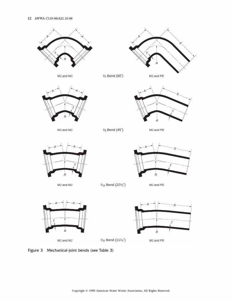
3 Mechanical-Joint Bends..................... 124 Mechanical-Joint Tees
and Crosses...................................... 175 Mechanical-Joint Base Bends............ 236 Mechanical-Joint Base Tees .............. 247 Mechanical-Joint Reducers ................ 258 Mechanical-Joint Tapped Tees.......... 289 Mechanical-Joint Offsets ................... 2910 Mechanical-Joint Sleeves................... 3010a Mechanical-Joint Split Sleeves.......... 3011 Mechanical-Joint Caps and Plugs..... 3112 Mechanical-Joint Connecting
Pieces................................................ 3213 Connecting Pieces, One-End
Flanged ............................................ 3314 Flange Details..................................... 3415 Base Drilling Details.......................... 3516 Flanged Bends .................................... 36
v
Copyright © 1999 American Water Works Association, All Rights Reserved.
SEC. PAGE SEC. PAGE
17 Flanged Tees and Crosses.................. 3718 Flanged Base Bends ........................... 4119 Flanged Base Tees .............................. 4220 Flanged Reducers................................ 43
Tables
1 Mechanical-Joint Dimensions—in. .... 102 Plain-End Dimensions and
Tolerances for Mechanical-Joint Fittings ................................... 11
3 Mechanical-Joint Bends ..................... 134 Mechanical-Joint Tees
and Crosses ...................................... 175 Mechanical-Joint Base Bends ............ 236 Mechanical-Joint Base Tees............... 247 Mechanical-Joint Reducers ................ 25
8 Mechanical-Joint Tapped Tees.......... 289 Mechanical-Joint Offsets ................... 2910 Mechanical-Joint Sleeves................... 3011 Mechanical-Joint Caps and Plugs..... 3112 Mechanical-Joint Connecting
Pieces................................................ 3213 Connecting Pieces, One-End
Flanged ............................................ 3314 Flange Details..................................... 3415 Base Drilling Details.......................... 3516 Flanged Bends .................................... 3617 Flanged Tees and Crosses ................. 3718 Flanged Base Bends........................... 4119 Flanged Base Tees.............................. 4220 Flanged Reducers ............................... 43A.1 Flange Gasket Details........................ 46
vi
Copyright © 1999 American Water Works Association, All Rights Reserved.
Foreword
This foreword is for information only and is not a part of ANSI/AWWA C110/A21.10.
I. Introduction.I.A. Background. American National Standards Committee A21 on Cast-Iron
Pipe and Fittings was organized in 1926 under the sponsorship of the American GasAssociation (A.G.A.), the American Society for Testing and Materials (ASTM), theAmerican Water Works Association (AWWA), and the New England Water WorksAssociation (NEWWA). Between 1972 and 1984, the cosecretariats were A.G.A.,AWWA, and NEWWA, with AWWA serving as administrative secretariat. In 1984,the committee became an AWWA committee with the name AWWA StandardsCommittee A21 on Ductile Iron Pipe and Fittings. In 1988, NEWWA withdrew as aseparate secretariat; however, it continues to maintain its representation on the A21Committee. In 1997, A.G.A. withdrew as cosecretariat.
The present scope of Committee A21 activity is the preparation of standards forcast-iron and ductile-iron pressure pipe for gas, water, and other liquids, and fittingsfor use with such pipe. These standards include design, dimensions, materials,coatings, linings, joints, accessories, and methods of inspection and testing.
The work of Committee A21 is conducted by subcommittees. The scope ofSubcommittee 3, Fittings, includes the periodic review of all current A21 standardsfor fittings and the preparation of revisions and new standards, when needed, forfittings to be used with cast-iron and ductile-iron pressure pipe included in A21standards.
I.B. History. The evolution of AWWA and ANSI standards for fittings ispresented in this foreword to provide information relating to systems having agedcast-iron pipe and fittings still in service.
The earliest record of an AWWA standard for cast-iron pipe is contained in theReport of Proceedings of the Tenth Annual Meeting of the American Water WorksAssociation (1890). In 1902, NEWWA adopted a more detailed standard titled“Standard Specification for Cast Iron Pipe and Special Castings.”
The next AWWA standard for pipe and fittings, AWWA 7C.1-1908, was approvedMay 12, 1908. A second edition, AWWA C100-52T, was approved by AWWA Dec. 31,1952, and by NEWWA Jan. 23, 1953. The third edition, AWWA C100-54T, wasapproved by AWWA Oct. 25, 1954, and finally issued as AWWA C100-55, having beenadvanced from tentative to standard without change June 17, 1955. AWWA C100-55covered fittings in the size range 4 to 60 in. (102 to 1,500 mm).* The fittings were allbell and spigot (caulked joint) of the so-called long-radius design. The outsidediameter (OD) for spigots varied with wall thicknesses, which were designated classesA, B, C, and D. Fittings 4 to 12 in. (102 to 305 mm) were made to class D patterns,having only one OD and pressure rating. Fittings 14 to 24 in. (356 to 610 mm) in sizewere furnished in classes B and D, and fittings 30 to 60 in. (762 to 1,500 mm) in sizewere furnished in classes A, B, C, and D. All fittings made in accordance with AWWA7C.1-1908 and C100-55 had the class identification cast on the fitting.
*Metric conversions given in this standard are direct conversions of US customary unitsand are not those specified in the International Organization for Standardization (ISO)standards.
vii
Copyright © 1999 American Water Works Association, All Rights Reserved.
ASA* A21.10-1952 (AWWA C110-52) was approved by ASA Sept. 30, 1952,following approval by AWWA May 4, 1951. The standard covered 3- to 12-in. (76- to305-mm) fittings of the so-called short-body design, which were the subject ofextensive research and tests by Committee A21. The rated pressure given by thestandard was 250 psi (1,724 kPa) plus water hammer. The standard provided a safetyfactor of 2.5 plus water hammer based on burst tests. Hydraulic losses weredetermined and compared with those found with long-radius fittings manufacturedin accordance with AWWA Standards. The minimum grade of cast iron in thestandard was 25,000 psi (172.4 MPa) tensile strength.
ASA A21.10-1964 (AWWA C110-64) was approved by ASA Jan. 9, 1964. Therevision covered 2- to 48-in. (50- to 1,219-mm) fittings. The design of the 14- to 48-in.(356- to 1,219-mm) fittings in the revision was based on an exhaustive series of bursttests. The minimum grade of cast iron (25,000 psi [172.4 MPa] tensile strength) wasretained, and higher grades up to 35,000 psi (241.3 MPa) tensile strength were usedto secure higher pressure ratings without radically changing the thicknesses. Ductileiron, grade 80-60-03, was also added in the 14- to 48-in. (356- to 1,219-mm) sizes witha rated working pressure of 250 psi (1,724 kPa), having the same wall thicknesses as150-psi (1,034-kPa)-rated gray-iron fittings. The minimum safety factor based onburst tests of representative fittings of the weakest type was three times the ratedworking pressure. Tables for flanged fittings and mechanical-joint fittings wereadded for the first time.
ANSI A21.10-1971 (AWWA C110-71) was approved by ANSI July 14, 1971.Ductile-iron fittings were added in sizes 3 to 12 in. (76 to 305 mm) and were rated for350 psi (2,413 kPa) working pressure. The grade of ductile iron was changed to70-50-05 to provide greater toughness. The safety factor against bursting was threetimes the rated working pressure. If required by the purchaser on special order,fittings were required to withstand a hydrostatic proof test not to exceed one and onehalf times the rated working pressure without leaks or permanent distortions.
ANSI A21.10a-1972 (AWWA C110a-72) was approved Dec. 17, 1972, as asupplement to ANSI A21.10-1971. The pressure rating for 14- to 24-in. (356- to 610-mm)ductile-iron fittings was increased to 350 psi (2,413 kPa).
ANSI/AWWA C110-77 (ANSI A21.10) was approved by ANSI Apr. 7, 1977. Themajor change in this revision was the discontinuance of bell-and-spigot fittings (caulkedjoints) and 2- and 21⁄4-in. (50- and 56-mm) fittings in the standard. These actionswere taken because the use of caulked joints had steadily declined until their use hadbecome a rarity and the 2- and 21⁄4-in. (50- and 56-mm) sizes were no longermanufactured in the United States. (Bell-and-spigot fittings are still available from somefoundries on special order.) With the elimination of 2- and 21⁄4-in. (50- and 56-mm)sizes, the standard included 3- to 48-in. (76- to 1,219-mm) mechanical-joint and flangedfittings only.
Another change made in the 1977 edition was in bolt lengths for flanged fittingsto comply with ANSI/AWWA C115/A21.15-75, Standard for Flanged Cast-Iron andDuctile-Iron Pipe With Threaded Flanges. Appendix A was added to the standard tocover bolts, gaskets, and the installation of flanged fittings. Appendix B was added asa listing of available special fittings that are not a part of the standard. These include
*American Standards Association (ASA) is the former name of the American NationalStandards Institute.
viii
Copyright © 1999 American Water Works Association, All Rights Reserved.
reducing bends, Y-branches, blind flanges, reducing tees, bullhead tees, flaredfittings, side-outlet tees and elbows, and wall pipe.
The following note introduced in the 1977 edition cautioned about usingmechanical-joint fittings with aged existing cast-iron pipe:
NOTE: Care should be used when connecting mechanical-joint fittings to agedexisting cast-iron pipe. The outside diameter of aged pipe should be measured priorto cutting since some of the older pipe was manufactured to a larger diameter than ispresently specified in A21 standards. Mechanical-joint sleeves or bell-and-spigot(caulked-joint) sleeves are available to provide transition from existing cast-iron pipe;however, they must be specified on the purchase order. Center to bottom-of-socketdimensions (dimension A in Table 3 and dimension J in Table 4 of this standard) forA21.10 mechanical-joint fittings are the same as the center to bottom-of-socketdimensions for bell-and-spigot (caulked-joint) fittings specified in the 1971 andprevious editions of A21.10. The following standards contain reference dimensionsuseful in classifying existing cast-iron pipe:
AWWA 7C.1-1908 (AWWA C100-55), Standard Specifications for Cast IronPressure Fittings, Table 1.
ASA A21.2-1953 (AWWA C102-53), American Standard for Cast Iron Pit CastPipe for Water or Other Liquids, Tables 2.1 and 2.2.
ANSI A21.6-1975 (AWWA C106-75), American National Standard for Cast-IronPipe Centrifugally Cast in Metal Molds for Water or Other Liquids, Tables 6.4, 6.5,and 6.6.
ANSI A21.8-1975 (AWWA C108-75), American National Standard for Cast IronPipe Centrifugally Cast in Sand-Lined Molds for Water or Other Liquids, Tables 8.4,8.5, and 8.6.
ANSI/AWWA C151/A21.51-86, American National Standard for Ductile IronPipe Centrifugally Cast in Metal Molds or Sand-Lined Molds for Water or OtherLiquids, Tables 51.4 and 51.5.
ANSI/AWWA C110/A21.10-82, as approved by ANSI Aug. 24, 1982, introducedno major revisions.
ANSI/AWWA C153/A21.53-84 (First Edition), American National Standard forDuctile-Iron Compact Fittings, 3 In. through 12 In. (76 mm through 305 mm), forWater and Other Liquids, was approved by ANSI Feb. 4, 1985. This standard,developed by Standards Committee A21, Subcommittee 3, Fittings, presents compactfittings designed to use the attendant strength of ductile iron.
ANSI/AWWA C110/A21.10-87 was approved by ANSI Oct. 30, 1987. The majorrevisions included new sections on rejection of fittings and determination of rejection,and ductile-iron grade 60-42-10 was added. Cast marking of the country where castwas added; Sec. 10-4.3, Joint Accessories, was added; and 14-in. through 48-in. (356-mmthrough 1,219-mm) solid sleeves made with B-pattern equipment were added.
ANSI/AWWA C110/A21.10-93 was approved by ANSI Aug. 10, 1993. Majorrevisions in this edition of the standard included the addition of a section on healtheffects and permeation, allowance for reduced metal-section thicknesses for ductile-iron glands, addition of a precautionary note on the use of flange gaskets thinnerthan 1⁄8 in. (3.2 mm) in appendix A, addition of flanged-joint bolt tightening sequenceto appendix A, and the addition of a section on ring gaskets in appendix A.
I.C. Acceptance. In May 1985, the US Environmental Protection Agency(USEPA) entered into a cooperative agreement with a consortium led by NSFInternational (NSF) to develop voluntary third-party consensus standards and acertification program for all direct and indirect drinking water additives. Other
ix
Copyright © 1999 American Water Works Association, All Rights Reserved.
members of the original consortium included the American Water Works AssociationResearch Foundation (AWWARF) and the Conference of State Health and Environ-mental Managers (COSHEM). The American Water Works Association (AWWA) andthe Association of State Drinking Water Administrators (ASDWA) joined later.
In the United States, authority to regulate products for use in, or in contactwith, drinking water rests with individual states.* Local agencies may choose toimpose requirements more stringent than those required by the state. To evaluatethe health effects of products and drinking water additives from such products, stateand local agencies may use various references, including
1. An advisory program formerly administered by USEPA, Office of DrinkingWater, discontinued on Apr. 7, 1990.
2. Specific policies of the state or local agency.3. Two standards developed under the direction of NSF, ANSI†/NSF‡ 60,
Drinking Water Treatment Chemicals—Health Effects, and ANSI/NSF 61, DrinkingWater System Components—Health Effects.
4. Other references, including AWWA standards, Food Chemicals Codex,Water Chemicals Codex,§ and other standards considered appropriate by the state orlocal agency.
Various certification organizations may be involved in certifying products inaccordance with ANSI/NSF 61. Individual states or local agencies have authority toaccept or accredit certification organizations within their jurisdiction. Accreditationof certification organizations may vary from jurisdiction to jurisdiction.
Appendix A, “Toxicology Review and Evaluation Procedures,” to ANSI/NSF 61does not stipulate a maximum allowable level (MAL) of a contaminant for substancesnot regulated by a USEPA final maximum contaminant level (MCL). The MALs of anunspecified list of “unregulated contaminants” are based on toxicity testingguidelines (noncarcinogens) and risk characterization methodology (carcinogens). Useof Appendix A procedures may not always be identical, depending on the certifier.
ANSI/AWWA C110/A21.10 does not address additives requirements. Thus, usersof this standard should consult the appropriate state or local agency havingjurisdiction in order to
1. Determine additives requirements, including applicable standards.2. Determine the status of certifications by all parties offering to certify
products for contact with, or treatment of, drinking water.3. Determine current information on product certification.
II. Special Issues.II.A. Advisory Information on Product Application. Unless otherwise provided
in the purchaser’s specifications, all fittings and accessories shall comply with thisstandard. Fittings and accessories not complying with this standard shall be replacedby the manufacturer at the agreed point of delivery. The manufacturer shall not beliable for shortages or damaged fittings after the fitting is accepted at the agreed
*Persons in Canada, Mexico, and non-North American countries should contact theappropriate authority having jurisdiction.
†American National Standards Institute, 11 W. 42nd St., New York, NY 10036.
‡NSF International, 3475 Plymouth Rd., Ann Arbor, MI 48106.
§Both publications available from National Academy of Sciences, 2102 Constitution Ave.N.W., Washington, DC 20418.
x
Copyright © 1999 American Water Works Association, All Rights Reserved.
point of delivery, except as recorded on the delivery receipt or similar document bythe carrier’s agent.
III. Use of This Standard.AWWA has no responsibility for the suitability or compatibility of the provisions
of this standard to any intended application by any user. Accordingly, each user ofthis standard is responsible for determining that the standard’s provisions aresuitable for and compatible with that user’s intended application.
III.A. Purchaser Options and Alternatives. This standard includes certainoptions that, if desired, must be specified in the purchaser’s specifications. It is alsonecessary that such options be included on the purchase order. Also, a number ofitems must be specified to describe completely the fittings required. The following listsummarizes the details and available options, and references the sections of thestandard where they are found.
1. Size, joint type, pressure rating (Sec. 1.1 and tables).2. Joint requirements (Sec. 4.2.1 and 4.2.2).3. Type of iron (Sec. 4.2.4).4. End combinations (Sec. 4.2.5).5. Certification by manufacturer (Sec. 5.1.3).6. Inspection by purchaser (Sec. 5.2).7. Elimination of cement-mortar lining (Sec. 4.3.2). Experience has indicated
that the petroleum asphaltic inside coating is not complete protection against loss inpipe capacity caused by tuberculation. Cement-mortar linings are recommended formost waters.
8. Special coatings and linings (Sec. 4.3.3).9. Acceptance tests (Sec. 5.4).
10. Special tests (Sec. 5.6).11. Special flange bolt-hole orientation (Sec. 4.4.3).III.B. Special Service Requirements. The following special service requirements
should be noted:1. The fittings for which this standard is intended are those normally used for
water. Fittings for other services may require special consideration by the purchaser.2. The method of installation of fittings depends on the type of joint and
should be made in accordance with applicable parts of ANSI/AWWA C111/A21.11,Rubber-Gasket Joints for Ductile-Iron and Gray-Iron Pressure Pipe and Fittings;ANSI/AWWA C600, Installation of Ductile-Iron Water Mains and Their Appurte-nances; and recommendations of manufacturers regarding their product.
3. Attention is directed to an apparent conflict between this standard andASME/ANSI B16.1, Cast Iron Pipe Flanges and Flanged Fittings, with regard topressure ratings for flanged fittings.
In ANSI/AWWA C110/A21.10, flanged joint fittings are rated for 150 or 250 psi(1,034 or 1,724 kPa) working pressure, depending on the material, that is, gray ironor ductile iron; the wall thickness of gray iron; and the size of the fitting. The ratingsof these fittings were established on the basis of hydrostatic testing of fittings tobursting and provide for a factor of safety of at least 3.0 at the rated workingpressure and at ambient temperature. ANSI/AWWA C110/A21.10 flanges that areadequate for water service of 250 psi (1,724 kPa) working pressure have facing anddrilling identical to ASME/ANSI B16.1 class 125 flanges, and match class 125 B16.1flanges, that for service at –20° to 150°F (–28.9° to 65.6°C) are rated for only 150 to200 psi (1,034 to 1,724 kPa), depending on the flange size and the class or grade of iron.
xi
Copyright © 1999 American Water Works Association, All Rights Reserved.
ASME/ANSI B16.1 covers both separate flanges and flanged fittings of gray ironfor service at both ambient and elevated temperatures. The pressure-temperatureratings of these flanges, as set forth in ASME/ANSI B16.1 and stated on the flyleafof that standard, are not based on burst strength, but have evolved over an extendedperiod of time of satisfactory performance in a wide range of general serviceconditions. These ratings encompass pressure combined with elevated temperature,stresses imposed by piping, thermal stresses due to temperature variations, andmany other conditions causing stress in the flange or fitting.
ASME/ANSI B16.1 also contains the design of a class 250 flange, which is muchheavier, has a larger bolt circle, and uses larger-sized bolts than the B16.1 class 125flange and the flanges covered in ANSI/AWWA C115/A21.15 and this standard.ASME/ANSI B16.1 class 250 flanges will not connect to the B16.1 class 125 flange,the ANSI/AWWA C115/A21.15 flange, or the ANSI/AWWA C110/A21.10 flange.
4. Although this standard does not detail the orientation of bolt holes in theflanges of the mechanical joint, it is at times convenient or necessary to have the boltholes specially oriented. The normal but not universal practice is to have the bolt holesstraddle the vertical centerline of the fittings, valves, and hydrants. (The verticalcenterline of a fitting is determined when the fitting is in the position to change thedirection of fluid flowing in a horizontal plane. With standard base bends andstandard base tees, the vertical centerline is determined when the fitting is in aposition to change the fluid flowing in a vertical plane.) If special orientation isknown to be necessary, it should be stated on the purchase order.
III.C. Modification to Standard. Any modification to the provisions, definitions,or terminology in this standard must be provided in the purchaser’s specifications.
IV. Major Revisions. The major revisions made to this standard in thisedition are as follows:
1. The format has been changed to AWWA standard style.2. Section I.A, Background, was revised to recognize the withdrawal of the
American Gas Association as cosecretariat of the A21 Committee.3. The acceptance clause (Sec. I.C) has been revised to approved wording.4. The advisory information paragraph (Sec. II.A) was revised and moved
from the body of the standard into the foreword.5. The scope of the standard has been limited to water service and all
references to gas and other liquids have been eliminated.6. The scope was amended to recognize 350-psi (2,413-kPa) ratings for 12-in.
(305-mm) and smaller flanged ductile-iron fittings when used with special gaskets.7. Cement-mortar linings (Sec. 4.3.2) was revised to reflect the optional
status of seal coat in the latest revision of ANSI/AWWA C104/A21.4.8. Special coatings and linings (Sec. 4.3.3) was revised to include asphaltic
material as a special lining.9. Table 1 was revised in accordance with the 1995 revision of ANSI/AWWA
C111/A21.11. Revisions include plus tolerances on the K1, K2, and L dimensions;longer bolt lengths for the 42- and 48-in. (1,067- and 1,219-mm) sizes; and thefootnote on ductile-iron glands.
10. Tables 16 through 19 on flanged fittings were revised to show the use ofductile iron for 3- to 12-in. (76- to 305-mm) flanged fittings with the same dimensionsas gray-iron fittings. Explanatory footnotes were also added.
11. The gaskets section of appendix A was revised to describe the rubbermaterial as being synthetic.
xii
Copyright © 1999 American Water Works Association, All Rights Reserved.
V. Comments. If you have any comments or questions about this standard,please call the AWWA Volunteer and Technical Support Group, (303) 794-7711 ext.6283, FAX (303) 795-1440, or write to the department at 6666 W. Quincy Ave.,Denver, CO 80235.
xiii
Copyright © 1999 American Water Works Association, All Rights Reserved.

This page intentionally blank.
Copyright © 1999 American Water Works Association, All Rights Reserved.Copyright © 1999 American Water Works Association, All Rights Reserved.
R
American Water Works Association
ANSI/AWWA C110/A21.10-98(Revision of ANSI/AWWA C110/A21.10-93)
AMERICAN NATIONAL STANDARD FOR
DUCTILE-IRON AND GRAY-IRON
FITTINGS, 3 IN. THROUGH 48 IN.
(76 mm THROUGH 1,219 mm),
FOR WATER
SECTION 1: GENERAL
Sec. 1.1 Scope
This standard covers 3- to 48-in. (76- to 1,219-mm) gray-iron and/or ductile-ironfittings to be used with ductile-iron pipe for water. Requirements for fittings withmechanical joints and flanged joints are listed in Tables 1 through 20 at the end ofthis standard. This standard may also be used for fittings with push-on joints or suchother joints as may be agreed on at the time of purchase.
For the 3- to 24-in. (76- to 610-mm) size range, ductile-iron mechanical-jointfittings and ductile-iron push-on-joint fittings are rated for 350 psi (2,413 kPa)working pressure. Ductile-iron flange-joint fittings are rated for 250-psi (1,724-kPa)working pressure; however, 12-in. (305-mm) and smaller sizes may be rated for350 psi (2,413 kPa) with the use of special gaskets. Gray-iron fittings having all typesof joints covered by this standard are rated for 150- or 250-psi (1,034- or 1,724-kPa)working pressures, as shown in the tables.
For the 30- to 48-in. (762- to 1,219-mm) size range, fittings with all types ofjoints covered by this standard are shown in the tables with rated working pressuresof 150 or 250 psi (1,034 or 1,724 kPa), depending on the type of iron as shown in thetables.
1
Copyright © 1999 American Water Works Association, All Rights Reserved.Copyright © 1999 American Water Works Association, All Rights Reserved.
2 AWWA C110-98/A21.10-98
Sec. 1.2 Purpose
The main purpose of this standard is to provide the minimum requirements forductile-iron and gray-iron fittings, 3 in. through 48 in. (76 mm through 1,219 mm),for water.
Sec. 1.3 Application
This standard can be referenced in specifications for ductile-iron and gray-ironfittings, 3 in. through 48 in. (76 mm through 1,219 mm), for water. The stipulationsof this standard apply when this document has been referenced and then only toductile-iron and gray-iron fittings, 3 in. through 48 in. (76 mm through 1,219 mm),for water.
SECTION 2: DEFINITIONS
The following definitions shall apply in this standard:1. Ductile iron: A cast ferrous material in which a major part of the carbon
content occurs as free graphite in a substantially nodular or spheroidal form.2. Flange joint: The flanged and bolted joint as detailed in Figure 14 and
Table 14.3. Gray iron: The cast ferrous material in which a major part of the carbon
content occurs as free graphite in the form of flakes interspersed throughout themetal.
4. Manufacturer: The party that manufactures, fabricates, or producesmaterials or products.
5. Mechanical joint: The gasketed and bolted joint as detailed in the latestrevision of ANSI/AWWA C111/A21.11.
6. Purchaser: The person, company, or organization that purchases anymaterials or work to be performed.
7. Push-on joint: The single rubber-gasket joint as set forth in the latestrevision of ANSI/AWWA C111/A21.11.
SECTION 3: REFERENCES
This standard references the following documents. In their latest editions, theyform a part of this standard to the extent specified within the standard. In any caseof conflict, the requirements of this standard shall prevail.
ASME*/ANSI† B16.1—Cast Iron Pipe Flanges and Flanged Fittings.ASTM‡ A48—Standard Specification for Gray Iron Casting.
*American Society of Mechanical Engineers, United Engineering Center, 345 E. 47th St., New York,NY 10017.
†American National Standards Institute, 11 W. 42nd St., New York, NY 10036.
‡American Society for Testing and Materials, 100 Barr Harbor Dr., West Conshohocken, PA19428-2959.
Copyright © 1999 American Water Works Association, All Rights Reserved.
DUCTILE-IRON AND GRAY-IRON FITTINGS FOR WATER 3
ASTM A438—Standard Test Method for Transverse Testing of Gray Cast Iron.ASTM A536—Standard Specification for Ductile Iron Castings.ANSI/AWWA C104/A21.4—American National Standard for Cement-Mortar Lining
for Ductile-Iron Pressure Pipe and Fittings for Water.ANSI/AWWA C111/A21.11—American National Standard for Rubber-Gasket
Joints for Ductile-Iron Pressure Pipe and Fittings.ANSI/AWWA C153/A21.53—American National Standard for Ductile-Iron Compact
Fittings, 3 In. Through 24 In. (76 mm Through 610 mm) and 54 In. Through 64 In.(1,400 mm Through 1,600 mm), for Water Service.
ANSI/AWWA C600—Standard for Installation of Ductile-Iron Water Mains andTheir Appurtenances.
SECTION 4: REQUIREMENTS
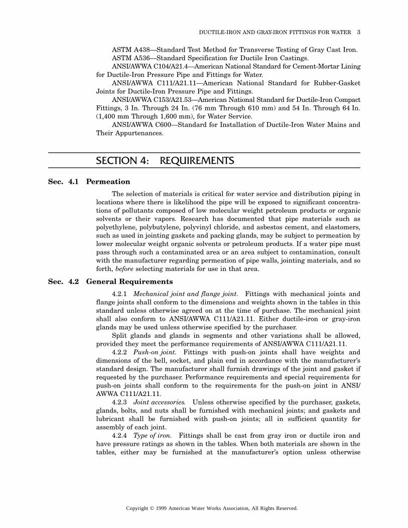
Sec. 4.1 Permeation
The selection of materials is critical for water service and distribution piping inlocations where there is likelihood the pipe will be exposed to significant concentra-tions of pollutants composed of low molecular weight petroleum products or organicsolvents or their vapors. Research has documented that pipe materials such aspolyethylene, polybutylene, polyvinyl chloride, and asbestos cement, and elastomers,such as used in jointing gaskets and packing glands, may be subject to permeation bylower molecular weight organic solvents or petroleum products. If a water pipe mustpass through such a contaminated area or an area subject to contamination, consultwith the manufacturer regarding permeation of pipe walls, jointing materials, and soforth, before selecting materials for use in that area.
Sec. 4.2 General Requirements
4.2.1 Mechanical joint and flange joint. Fittings with mechanical joints andflange joints shall conform to the dimensions and weights shown in the tables in thisstandard unless otherwise agreed on at the time of purchase. The mechanical jointshall also conform to ANSI/AWWA C111/A21.11. Either ductile-iron or gray-ironglands may be used unless otherwise specified by the purchaser.
Split glands and glands in segments and other variations shall be allowed,provided they meet the performance requirements of ANSI/AWWA C111/A21.11.
4.2.2 Push-on joint. Fittings with push-on joints shall have weights anddimensions of the bell, socket, and plain end in accordance with the manufacturer’sstandard design. The manufacturer shall furnish drawings of the joint and gasket ifrequested by the purchaser. Performance requirements and special requirements forpush-on joints shall conform to the requirements for the push-on joint in ANSI/AWWA C111/A21.11.
4.2.3 Joint accessories. Unless otherwise specified by the purchaser, gaskets,glands, bolts, and nuts shall be furnished with mechanical joints; and gaskets andlubricant shall be furnished with push-on joints; all in sufficient quantity forassembly of each joint.
4.2.4 Type of iron. Fittings shall be cast from gray iron or ductile iron andhave pressure ratings as shown in the tables. When both materials are shown in thetables, either may be furnished at the manufacturer’s option unless otherwise
Copyright © 1999 American Water Works Association, All Rights Reserved.
4 AWWA C110-98/A21.10-98
specified by the purchaser. All fittings shall be capable of withstanding, withoutbursting, hydrostatic tests of three times the rated water working pressure.
4.2.5 Other joint designs or dimensions. Standard fittings shall be furnishedwith the end combinations shown in the tables. When fittings of other designs ordimensions are purchased under this standard, the purchaser must specify the fittingdesign. Plain ends of mechanical-joint fittings may be furnished with bevels forassembly with push-on joint bells.
NOTE: Bell fittings without plain ends are most readily available.
Sec. 4.3 Coatings and Linings
4.3.1 Outside coating. The outside coating shall be a petroleum asphalticcoating approximately 1 mil (25 µm) thick. The coating shall be applied to the outsideof all fittings unless otherwise specified by the purchaser. The finished coating shallbe continuous, smooth, neither brittle when cold nor sticky when exposed to the sun,and strongly adherent to the fitting.
4.3.2 Cement-mortar linings. The lining for use under normal conditionsshall be a cement-mortar lining in accordance with the latest revision of ANSI/AWWA C104/A21.4, unless otherwise specified.* Cement-mortar linings are notnormally furnished in sleeves, plugs, or caps.
4.3.3 Special coatings and linings. For special conditions, other types of coat-ings and linings may be available. Special coatings and linings shall be specified bythe purchaser. One special lining for fittings that are not cement-mortar lined is anasphaltic material as thick as practicable, at least 1 mil (25 µm), that conforms to allappropriate requirements for seal coat, as described in the latest revision of ANSI/AWWA C104/A21.4.
Sec. 4.4 Special Requirements for Flanged Fittings
4.4.1 Flanges. Flanges shall conform to the dimensions shown in Table 14,which are adequate for the pressure ratings given in Sec. 4.2.2 of ANSI/AWWA C111/A21.11.
NOTE: The bolt circle and bolt holes of these flanges match those of ASME/ANSIB16.1 and can be joined with these class 125 flanges. Flanges of ANSI/AWWA C110/A21.10 fittings cannot be joined with class 250 B16.1 flanges.
4.4.2 Facing. Flanges shall be flat-faced without projection or raised-face andshall be furnished smooth or with shallow serrations. Flanges may be back-faced orspot-faced for compliance with the flange thickness tolerance set forth in thisstandard. Bearing surfaces for bolting shall be parallel to the flange face within 3°.
4.4.3 Bolt holes. Bolt holes shall be in accordance with the dimensions shownin Table 14. Bolt holes shall be equally spaced and shall straddle the centerlines ofthe flange as shown in Figure 14.
4.4.3.1. Misalignment of corresponding bolt holes of two opposing flanges shallnot exceed 0.12 in. (3.0 mm).
4.4.3.2. If bolt-hole orientation other than provided for in this standard isrequired by the purchaser, the special orientation shall be specified in the purchaser’sspecification.
*Experience indicates that the petroleum asphaltic inside coating is not complete protectionagainst loss in pipe capacity caused by tuberculation. Cement-mortar linings arerecommended for most waters.
Copyright © 1999 American Water Works Association, All Rights Reserved.
DUCTILE-IRON AND GRAY-IRON FITTINGS FOR WATER 5
4.4.4 Laying-length dimensions. Face-to-face dimensions shall conform to atolerance of ±0.06 in. (±1.5 mm) for sizes 3 to 10 in. (76 to 254 mm) and ±0.12 in.(±3.0 mm) for sizes 12 to 48 in. (305 to 1,219 mm). Center-to-face tolerances shall beone half those of face-to-face tolerances. The largest opening shall govern thetolerance for all openings.
SECTION 5: VERIFICATION
Sec. 5.1 Inspection and Certification by Manufacturer
5.1.1 Quality control and inspection practice. The manufacturer shall estab-lish the necessary quality control and inspection practice to ensure compliance withthis standard. All fittings shall be clean and sound without defects that could impairtheir service.
5.1.2 Repairs of defects. Repairing defects by welding or other methods shallnot be allowed if such repairs could adversely affect the serviceability of the fitting orits capability to meet the strength requirements of this standard.
5.1.3 Certification by manufacturer. If required by the purchaser, the manu-facturer shall furnish a sworn statement that the inspection and all the specifiedtests have been made and the results thereof comply with the requirements of thisstandard.
5.1.4 Manufacturer’s records. The results of the specified tests (Sec. 5.4, 5.5,5.6, and 5.9 if applicable) shall be recorded and retained for one year and shall beavailable to the purchaser at the manufacturer’s plant.
Sec. 5.2 Inspection by Purchaser
5.2.1 Purchaser’s obligations. If the purchaser desires to inspect fittings atthe manufacturer’s plant, it shall be stated in the purchaser’s specifications and theconditions described under which the inspection shall be made (such as time andextent of the inspection).
5.2.2 Manufacturer’s obligations. The purchaser’s representative shall havefree access to those areas of the manufacturer’s plant as are necessary to determinecompliance with this standard. The manufacturer shall make available for the use bythe purchaser’s representative such gauges as are necessary for inspection. Themanufacturer shall provide the purchaser’s representative with assistance asnecessary for the handling of fittings.
Sec. 5.3 Tolerances or Permitted Variations
5.3.1 Dimensions. Fittings shall be measured with suitable gauges at suffi-ciently frequent intervals to ensure that the dimensions comply with the require-ments of this standard. The smallest inside diameter (ID) of the sockets and theoutside diameter (OD) of the plain ends shall be tested with circular gauges. Othersocket dimensions shall be measured as appropriate.
Copyright © 1999 American Water Works Association, All Rights Reserved.
6 AWWA C110-98/A21.10-98
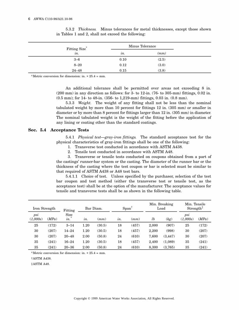
5.3.2 Thickness. Minus tolerances for metal thicknesses, except those shownin Tables 1 and 2, shall not exceed the following:
An additional tolerance shall be permitted over areas not exceeding 8 in.(200 mm) in any direction as follows: for 3- to 12-in. (76- to 305-mm) fittings, 0.02 in.(0.5 mm); for 14- to 48-in. (356- to 1,219-mm) fittings, 0.03 in. (0.8 mm).
5.3.3 Weight. The weight of any fitting shall not be less than the nominaltabulated weight by more than 10 percent for fittings 12 in. (305 mm) or smaller indiameter or by more than 8 percent for fittings larger than 12 in. (305 mm) in diameter.The nominal tabulated weight is the weight of the fitting before the application ofany lining or coating other than the standard coatings.
Sec. 5.4 Acceptance Tests
5.4.1 Physical test—gray-iron fittings. The standard acceptance test for thephysical characteristics of gray-iron fittings shall be one of the following:
1. Transverse test conducted in accordance with ASTM A438.2. Tensile test conducted in accordance with ASTM A48.3. Transverse or tensile tests conducted on coupons obtained from a part of
the castings’ runner-bar system or the casting. The diameter of the runner bar or thethickness of the casting where the test coupon or bar is selected must be similar tothat required of ASTM A438 or A48 test bars.
5.4.1.1 Choice of test. Unless specified by the purchaser, selection of the testbar coupon and test method (either the transverse test or tensile test, as theacceptance test) shall be at the option of the manufacturer. The acceptance values fortensile and transverse tests shall be as shown in the following table.
Fitting Size*
in.
*Metric conversion for dimension: in. × 25.4 = mm.
Minus Tolerance
in. (mm)
3–6 0.10 (2.5)
8–20 0.12 (3.0)
24–48 0.15 (3.8)
Iron Strength Fitting Sizein.*
*Metric conversion for dimension: in. × 25.4 = mm.
Bar Diam. Span†
†ASTM A438.
Min. Breaking Load
Min. Tensile Strength‡
‡ASTM A48.
psi(1,000s) (MPa) in. (mm) in. (mm) lb (kg)
psi(1,000s) (MPa)
25 (172) 3–14 1.20 (30.5) 18 (457) 2,000 (907) 25 (172)
30 (207) 14–24 1.20 (30.5) 18 (457) 2,200 (998) 30 (207)
30 (207) 20–48 2.00 (50.8) 24 (610) 7,600 (3,447) 30 (207)
35 (241) 16–24 1.20 (30.5) 18 (457) 2,400 (1,089) 35 (241)
35 (241) 20–36 2.00 (50.8) 24 (610) 8,300 (3,765) 35 (241)
Copyright © 1999 American Water Works Association, All Rights Reserved.
DUCTILE-IRON AND GRAY-IRON FITTINGS FOR WATER 7
For 20-in. (508-mm) and 24-in. (610-mm) fittings with a body thickness greaterthan 1 in. (25.4 mm), a 2-in. (50.8-mm) test bar shall be used.
5.4.2 Physical test—ductile-iron fittings. The standard acceptance test for thephysical characteristics of ductile-iron fittings shall be a tensile test on coupons castfrom the same iron as the fittings.
Except as otherwise provided herein, coupons shall be cast and the test made inaccordance with ASTM A536. The test coupon shall be obtained, at the manufac-turer’s option, from one of the following: (1) the ASTM A536 keel block, modified keelblock, or Y-block separately cast coupon; (2) the castings’ runner-bar system, providedthat the diameter of the runner bar at the location the coupon is selected is similarto the respective ASTM A536 coupon; or (3) the casting.
5.4.2.1 Acceptance value. The standard grade of iron shall be 70-50-05, withacceptance values as follows: minimum tensile strength, 70,000 psi (483 MPa);minimum yield strength, 50,000 psi (345 MPa); minimum elongation, 5 percent.
Another permissible acceptance value shall be the 60-42-10 grade of iron, withacceptance values as follows: minimum tensile strength, 60,000 psi (414 MPa);minimum yield strength, 42,000 psi (290 MPa); and minimum elongation, 10 percent;provided the manufacturer of fittings produced from this grade can furnish records todemonstrate that such fittings meet the performance test requirements of thisstandard.
5.4.3 Sampling. At least one sample shall be taken during each period ofapproximately 3 h, while the melting unit is operated continuously.
Sec. 5.5 Chemical Limitations
5.5.1 Gray-iron fittings. Analyses of the iron in gray-iron fittings shall bemade at sufficiently frequent intervals to ensure compliance with the followinglimits: phosphorus, 0.90 percent maximum; sulfur, 0.15 percent maximum.
Control of the other chemical constituents shall be maintained to meet thephysical property requirements of this standard. Samples for chemical analyses shallbe representative and shall be obtained from either acceptance-test specimens orspecimens cast for this purpose.
5.5.2 Ductile-iron fittings. Analyses of the iron shall be made at sufficientlyfrequent intervals to ensure compliance with the following limit: phosphorus, 0.08 percentmaximum. Control of other chemical constituents shall be maintained to meet thephysical property requirements of this standard.
Samples for chemical analyses shall be representative and shall be obtainedfrom either an acceptance-test specimen or specimens cast for this purpose.
Sec. 5.6 Additional Tests Required by the Purchaser
If tests other than those provided in this standard are required by thepurchaser, such tests shall be specified by the purchaser. Although it is not customaryto make hydrostatic proof tests of fittings at the foundry, such tests may be made onspecial order at additional cost. If proof tests at the foundry are required by thepurchaser for an order of fittings, the fittings shall withstand, without leaks orpermanent distortion, hydrostatic test pressures not to exceed one and one half timesthe rated water working pressures.
Copyright © 1999 American Water Works Association, All Rights Reserved.
8 AWWA C110-98/A21.10-98
Sec. 5.7 Defective Specimens and Retests
When any physical test specimen shows defective machining or lack ofcontinuity of metal, it shall be discarded and replaced by another specimen cast inthe same sampling period as the specimen that failed.
Sec. 5.8 Rejection of Fittings
If the test results of any sound specimen fail to meet the applicablerequirements of Sec. 5.4, or the chemical analyses do not conform to the limitationsof Sec. 5.5 where applicable, the fittings represented by these tests and/or analysesshall be rejected, except as provided in Sec. 5.9.
Sec. 5.9 Determining Rejection
The manufacturer may limit the amount of rejection by making additionalacceptance tests until the rejected lot is bracketed, in order of manufacture, by anacceptable test at each end of the interval in question.
SECTION 6: DELIVERY
Sec. 6.1 Marking
Fittings shall have distinctly cast on them the pressure rating, nominaldiameters of openings, manufacturer’s identification, country where cast, and thenumber of degrees or fraction of the circle on all bends. Ductile-iron fittings shallhave the letters “DI” or “Ductile” cast on them. Cast letters and figures shall be onthe outside body of the fitting and shall have dimensions no smaller than thefollowing:
Sec. 6.2 Packing and Shipping
This standard has no applicable information for this section.
Sec. 6.3 Affidavit of Compliance
This standard has no applicable information for this section.
Fitting Size*
in.
*Metric conversion for dimension: in. × 25.4 = mm.
Height of Letters Relief
in. (mm) in. (mm)
Less than 8 As large as practical As large as practical
8–10 3⁄4 (19) 3⁄32 (2.5)
12–48 11⁄4 (32) 3⁄32 (2.5)
Copyright © 1999 American Water Works Association, All Rights Reserved.
DUCTILE-IRON AND GRAY-IRON FITTINGS FOR WATER 9
���
��
�
���
��
����
�����
����
��
��
����
������
�������
�������
�������
�������
�������
������
����
��
��
���
���
���
���
���
���
�
X
M L
N
O P
K1K2 C F
0.12 in. (3.0 mm)
0.75 in.(19.1 mm)
0.19 in. (4.8 mm)
See Note 6
AJ D
B
NOTES:
S
2˚
˚7˚
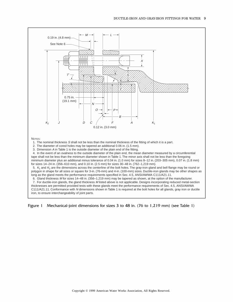
1. The nominal thickness S shall not be less than the nominal thickness of the fitting of which it is a part. 2. The diameter of cored holes may be tapered an additional 0.06 in. (1.5 mm). 3. Dimension A in Table 1 is the outside diameter of the plain end of the fitting. 4. In the event of an ovalness to the outside diameter of the plain end, the mean diameter measured by a circumferential tape shall not be less than the minimum diameter shown in Table 1. The minor axis shall not be less than the foregoing minimum diameter plus an additional minus tolerance of 0.04 in. (1.0 mm) for sizes 8–12 in. (203–305 mm), 0.07 in. (1.8 mm) for sizes 14–24 in. (356–610 mm), and 0.10 in. (2.5 mm) for sizes 30–48 in. (762–1,219 mm). 5. K1 and K2 are the dimensions across the centerline of the bolt holes. The gray-iron gland and bell flange may be round or polygon in shape for all sizes or square for 3-in. (76-mm) and 4-in. (100-mm) sizes. Ductile-iron glands may be other shapes aslong as the gland meets the performance requirements specified in Sec. 4.5, ANSI/AWWA C111/A21.11. 6. Gland thickness M for sizes 14–48 in. (356–1,219 mm) may be tapered as shown, at the option of the manufacturer. 7. For ductile-iron glands, the gland thickness M listed above is not applicable. Designs incorporating reduced metal-section thicknesses are permitted provided tests with these glands meet the performance requirements of Sec. 4.5, ANSI/AWWA C111/A21.11. Conformance with N dimensions shown in Table 1 is required at the bolt holes for all glands, gray iron or ductile iron, to ensure interchangeability of joint parts.
Figure 1 Mechanical-joint dimensions for sizes 3 to 48 in. (76 to 1,219 mm) (see Table 1)
Copyright © 1999 American Water Works Association, All Rights Reserved.
10A
WW
AC
110-98/A21.10-98
ittings for these sizes. These longer ANSI/AWWA 3 and Figure 4 of ANSI/AWWA C111/A21.11.
ded tests with these glands meet the performanceon, to ensure interchangeability of joint parts.
Bolts†
O P S No. Size Length
.31 0.63 0.52–0.10
4 5⁄8 3
.31 0.75 0.65–0.10
4 3⁄4 31⁄2
.31 0.75 0.70–0.10
6 3⁄4 31⁄2
.31 0.75 0.75–0.12
6 3⁄4 4
.31 0.75 0.80–0.12
8 3⁄4 4
.31 0.75 0.85–0.12
8 3⁄4 4
.31 0.75 0.89–0.12
10 3⁄4 41⁄2
.31 0.75 0.97–0.12
12 3⁄4 41⁄2
.31 0.75 1.05–0.15
12 3⁄4 41⁄2
.31 0.75 1.12–0.15
14 3⁄4 41⁄2
.31 0.75 1.22–0.15
16 3⁄4 5
.38 1.00 1.50–0.15
20 1 6
.38 1.00 1.80–0.15
24 1 6
.38 1.00 1.95–0.15
28 11⁄4 6
.38 1.00 2.20–0.15
32 11⁄4 6
Co
pyrig
ht ©
19
99
Am
erica
n W
ate
r Wo
rks Asso
ciatio
n, A
ll Rig
hts R
ese
rved
.
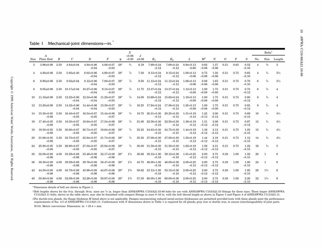
*Dimension details of bell are shown in Figure 1.†Bolt lengths shown for the 8-in. through 16-in. sizes are 1⁄2 in. longer than ANSI/AWWA C153/A21.53-88 bolts for use with ANSI/AWWA C153/A21.53 fC111/A21.11 bolts, shown in the table above, may also be furnished with compact fittings in sizes 8–16 in. with the bolt thread length as shown in Figure
‡For ductile-iron glands, the flange thickness M listed above is not applicable. Designs incorporating reduced metal-section thicknesses are permitted provirequirements of Sec. 4.5 of ANSI/AWWA C111/A21.11. Conformance with N dimensions shown in Table 1 is required for all glands, gray iron or ductile ir
NOTE: Metric conversions: Dimension: in. × 25.4 = mm.
Table 1 Mechanical-joint dimensions—in.*
APlain End
X+0.06–0.00
J±0.06Size B C D F φ K1 K2 L M‡ N
3 3.96±0.06 2.50 4.84±0.04 4.94+0.06–0.04
4.06+0.07–0.03
28° 3⁄4 6.19 7.69+0.24–0.12
7.69+0.24–0.12
0.94+0.13–0.60
0.62–0.06
1.37–0.06
0
4 4.80±0.06 2.50 5.92±0.40 6.02+0.06–0.04
4.90+0.07–0.03
28° 7⁄8 7.50 9.12+0.24–0.12
9.12+0.24–0.12
1.00+0.13–0.06
0.75–0.06
1.50–0.06
0
6 6.90±0.06 2.50 8.02±0.04 8.12+0.06–0.04
7.00+0.07–0.03
28° 7⁄8 9.50 11.12+0.24–0.12
11.12+0.24–0.12
1.06+0.13–0.06
0.88–0.06
1.63–0.06
0
8 9.05±0.06 2.50 10.17±0.04 10.27+0.06–0.04
9.15+0.07–0.03
28° 7⁄8 11.75 13.37+0.24–0.12
13.37+0.24–0.12
1.12+0.13–0.08
1.00–0.08
1.75–0.80
0
10 11.10±0.06 2.50 12.22+0.06–0.04
12.34+0.06–0.04
11.20+0.07–0.03
28° 7⁄8 14.00 15.69+0.24–0.12
15.62+0.24–0.12
1.19+0.13–0.08
1.00–0.08
1.75–0.08
0
12 13.20±0.06 2.50 14.32+0.06–0.04
14.44+0.06–0.04
13.30+0.07–0.03
28° 7⁄8 16.25 17.94+0.24–0.12
17.88+0.24–0.12
1.25+0.13–0.08
1.00–0.08
1.75–0.08
0
14 15.30+0.05–0.08
3.50 16.40+0.07–0.05
16.54+0.07–0.05
15.44+0.06–0.07
28° 7⁄8 18.75 20.31+0.30–0.12
20.25+0.30–0.12
1.31+0.19–0.12
1.25–0.12
2.00–0.12
0
16 17.40+0.05–0.08
3.50 18.50+0.07–0.05
18.64+0.07–0.05
17.54+0.06–0.07
28° 7⁄8 21.00 22.56+0.30–0.12
22.50+0.30–0.12
1.38+0.19–0.12
1.31–0.12
2.06–0.12
0
18 19.50+0.05–0.08
3.50 20.60+0.07–0.05
20.74+0.07–0.05
19.64+0.06–0.07
28° 7⁄8 23.25 24.83+0.30–0.15
24.75+0.30–0.15
1.44+0.19–0.12
1.38–0.12
2.13–0.12
0
20 21.60+0.05–0.08
3.50 22.70+0.07–0.05
22.84+0.07–0.05
21.74+0.06–0.07
28° 7⁄8 25.50 27.08+0.30–0.15
27.00+0.30–0.15
1.50+0.19–0.12
1.44–0.12
2.19–0.12
0
24 25.80+0.05–0.08
3.50 26.90+0.07–0.05
27.04+0.07–0.05
25.94+0.06–0.07
28° 7⁄8 30.00 31.58+0.30–0.15
31.50+0.30–0.15
1.62+0.19–0.12
1.56–0.12
2.31–0.12
0
30 32.00+0.08–0.06
4.00 33.29+0.08–0.06
33.46+0.08–0.06
32.17+0.08–0.06
20° 11⁄8 36.88 39.12+1.00–0.18
39.12+0.36–0.18
1.81+0.25–0.12
2.00–0.12
2.75–0.12
0
36 38.30+0.08–0.06
4.00 39.59+0.08–0.06
39.76+0.08–0.06
38.47+0.08–0.06
20° 11⁄8 43.75 46.00+1.00–0.18
46.00+0.36–0.18
2.00+0.25–0.12
2.00–0.12
2.75–0.12
0
42 44.50+0.08–0.06
4.00 45.79+0.08–0.06
45.96+0.08–0.06
44.67+0.08–0.06
20° 13⁄8 50.62 53.12+1.00–0.18
53.12+0.36–0.18
2.00+0.25–0.12
2.00–0.12
2.75–0.12
0
48 50.80+0.08–0.06
4.00 52.09+0.08–0.06
52.26+0.08–0.06
50.97+0.08–0.06
20° 13⁄8 57.50 60.00+1.00–0.18
60.00+0.36–0.18
2.00+0.25–0.12
2.00–0.12
2.75–0.12
0
DU
CT
ILE
-IRO
N A
ND
GR
AY-IR
ON
FIT
TIN
GS
FO
R W
AT
ER
11
Table 2 Plain-end dimensions and tolerances for mechanical-joint fittings
Sizein.
ODin.
T2in.
LSin.
3 3.96±0.06 0.48–0.10 5.5
4 4.80±0.06 0.47–0.10 5.5
6 6.90±0.06 0.50–0.10 5.5
8 9.05±0.06 0.54–0.12 5.5
10 11.10±0.06 0.60–0.12 5.5
12 13.20±0.06 0.68–0.12 5.5
14 15.30+0.05–0.08
0.66–0.12 8.0
16 17.40+0.05–0.08
0.70–0.12 8.0
18 19.50+0.05–0.08
0.75–0.12 8.0
20 21.60+0.05–0.08
0.80–0.12 8.0
24 25.80+0.05–0.08
0.80–0.15 8.0
30 32.00+0.08–0.06
1.03–0.15 8.0
36 38.30+0.08–0.06
1.15–0.15 8.0
42 44.50+0.08–0.06
1.28–0.15 8.0
48 50.80+0.08–0.06
1.42–0.15 8.0
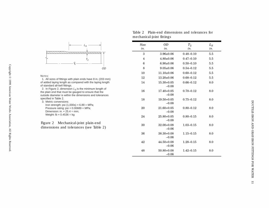
NOTES: 1. All sizes of fittings with plain ends have 8 in. (203 mm) of added laying length as compared with the laying length of standard all-bell fittings. 2. In Figure 2, dimension LS is the minimum length of the plain end that must be gauged to ensure that the outside diameter is within the dimensions and tolerances specified in Table 2. 3. Metric conversions:
Iron strength: psi (1,000s) × 6.89 = MPa;Pressure rating: psi × 0.00689 = MPa;Dimension: in. × 25.4 = mm;Weight: lb × 0.4536 = kg
����������������
T2
LS
OD
CL
Figure 2 Mechanical-joint plain-end dimensions and tolerances (see Table 2)
Co
pyrig
ht ©
19
99
Am
erica
n W
ate
r Wo
rks Asso
ciatio
n, A
ll Rig
hts R
ese
rved
.
12 AWWA C110-98/A21.10-98
MJ and MJ
R
T
A A
1⁄4 Bend (90˚) MJ and PE
R
T
A
S
MJ and MJ 1⁄16 Bend (221⁄2˚)
R
T
A A
MJ and PE
R
T
A S
MJ and MJ 1⁄32 Bend (111⁄4˚)
R
T
A A
MJ and PE
R
T
A S
MJ and MJ 1⁄8 Bend (45˚) MJ and PE
R
T
A AS
R
T
A
Figure 3 Mechanical-joint bends (see Table 3)
Copyright © 1999 American Water Works Association, All Rights Reserved.
DUCTILE-IRON AND GRAY-IRON FITTINGS FOR WATER 13
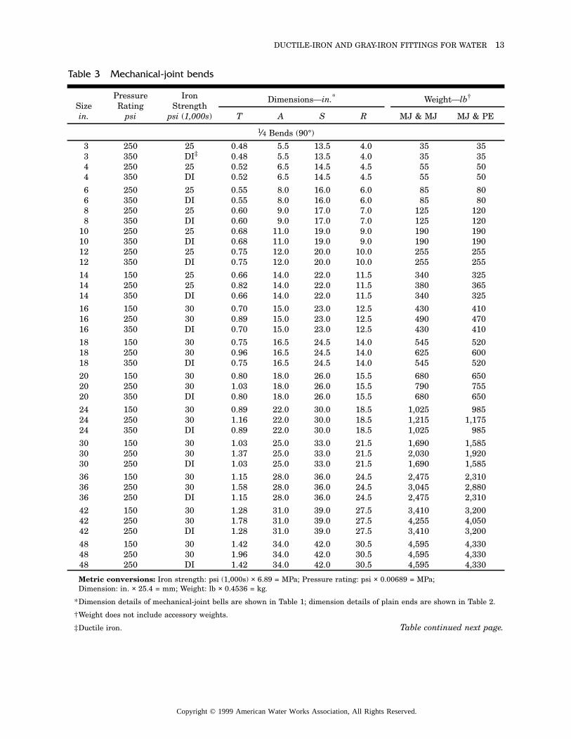
Metric conversions: Iron strength: psi (1,000s) × 6.89 = MPa; Pressure rating: psi × 0.00689 = MPa; Dimension: in. × 25.4 = mm; Weight: lb × 0.4536 = kg.
*Dimension details of mechanical-joint bells are shown in Table 1; dimension details of plain ends are shown in Table 2.
†Weight does not include accessory weights.
‡Ductile iron.
Table 3 Mechanical-joint bends
Sizein.
Pressure Rating
psi
Iron Strength
psi (1,000s)
Dimensions—in.* Weight—lb†
T A S R MJ & MJ MJ & PE
1⁄4 Bends (90°)
3 250 25 0.48 5.5 13.5 4.0 35 353 350 DI‡ 0.48 5.5 13.5 4.0 35 354 250 25 0.52 6.5 14.5 4.5 55 504 350 DI 0.52 6.5 14.5 4.5 55 50
6 250 25 0.55 8.0 16.0 6.0 85 806 350 DI 0.55 8.0 16.0 6.0 85 808 250 25 0.60 9.0 17.0 7.0 125 1208 350 DI 0.60 9.0 17.0 7.0 125 120
10 250 25 0.68 11.0 19.0 9.0 190 19010 350 DI 0.68 11.0 19.0 9.0 190 19012 250 25 0.75 12.0 20.0 10.0 255 25512 350 DI 0.75 12.0 20.0 10.0 255 255
14 150 25 0.66 14.0 22.0 11.5 340 32514 250 25 0.82 14.0 22.0 11.5 380 36514 350 DI 0.66 14.0 22.0 11.5 340 325
16 150 30 0.70 15.0 23.0 12.5 430 41016 250 30 0.89 15.0 23.0 12.5 490 47016 350 DI 0.70 15.0 23.0 12.5 430 410
18 150 30 0.75 16.5 24.5 14.0 545 52018 250 30 0.96 16.5 24.5 14.0 625 60018 350 DI 0.75 16.5 24.5 14.0 545 520
20 150 30 0.80 18.0 26.0 15.5 680 65020 250 30 1.03 18.0 26.0 15.5 790 75520 350 DI 0.80 18.0 26.0 15.5 680 650
24 150 30 0.89 22.0 30.0 18.5 1,025 98524 250 30 1.16 22.0 30.0 18.5 1,215 1,17524 350 DI 0.89 22.0 30.0 18.5 1,025 985
30 150 30 1.03 25.0 33.0 21.5 1,690 1,58530 250 30 1.37 25.0 33.0 21.5 2,030 1,92030 250 DI 1.03 25.0 33.0 21.5 1,690 1,585
36 150 30 1.15 28.0 36.0 24.5 2,475 2,31036 250 30 1.58 28.0 36.0 24.5 3,045 2,88036 250 DI 1.15 28.0 36.0 24.5 2,475 2,310
42 150 30 1.28 31.0 39.0 27.5 3,410 3,20042 250 30 1.78 31.0 39.0 27.5 4,255 4,05042 250 DI 1.28 31.0 39.0 27.5 3,410 3,200
48 150 30 1.42 34.0 42.0 30.5 4,595 4,33048 250 30 1.96 34.0 42.0 30.5 4,595 4,33048 250 DI 1.42 34.0 42.0 30.5 4,595 4,330
Table continued next page.
Copyright © 1999 American Water Works Association, All Rights Reserved.
14 AWWA C110-98/A21.10-98
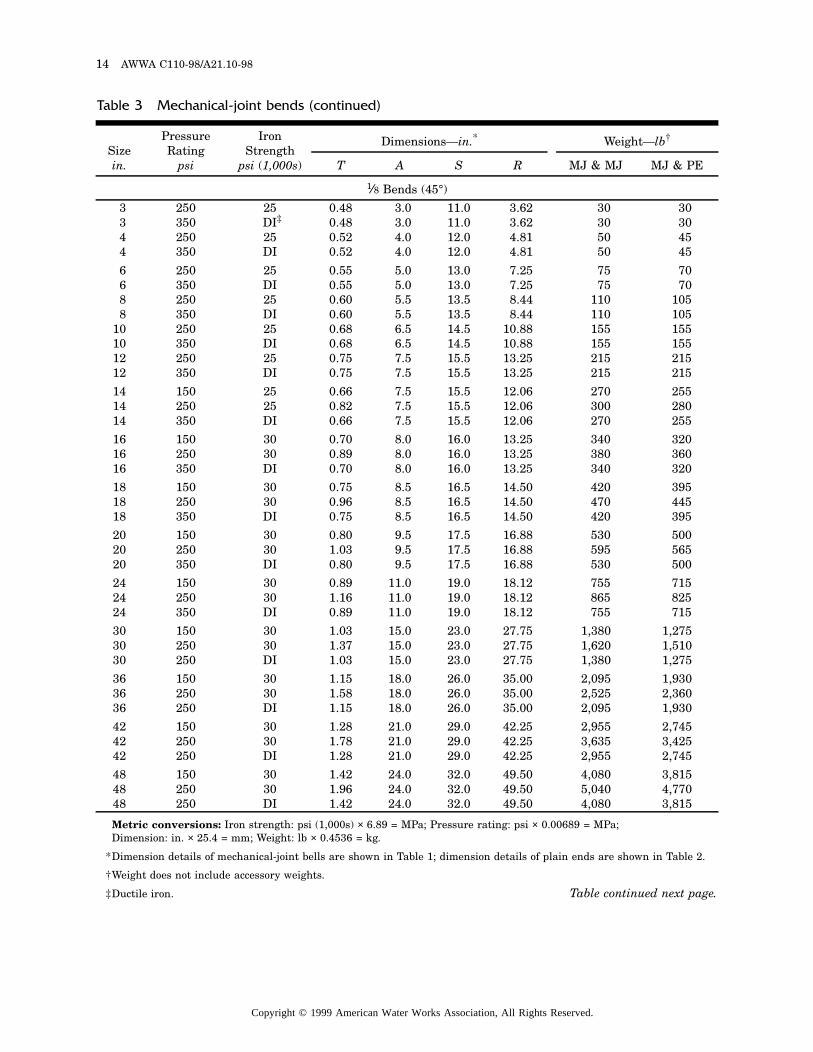
Metric conversions: Iron strength: psi (1,000s) × 6.89 = MPa; Pressure rating: psi × 0.00689 = MPa; Dimension: in. × 25.4 = mm; Weight: lb × 0.4536 = kg.
*Dimension details of mechanical-joint bells are shown in Table 1; dimension details of plain ends are shown in Table 2.
†Weight does not include accessory weights.
‡Ductile iron.
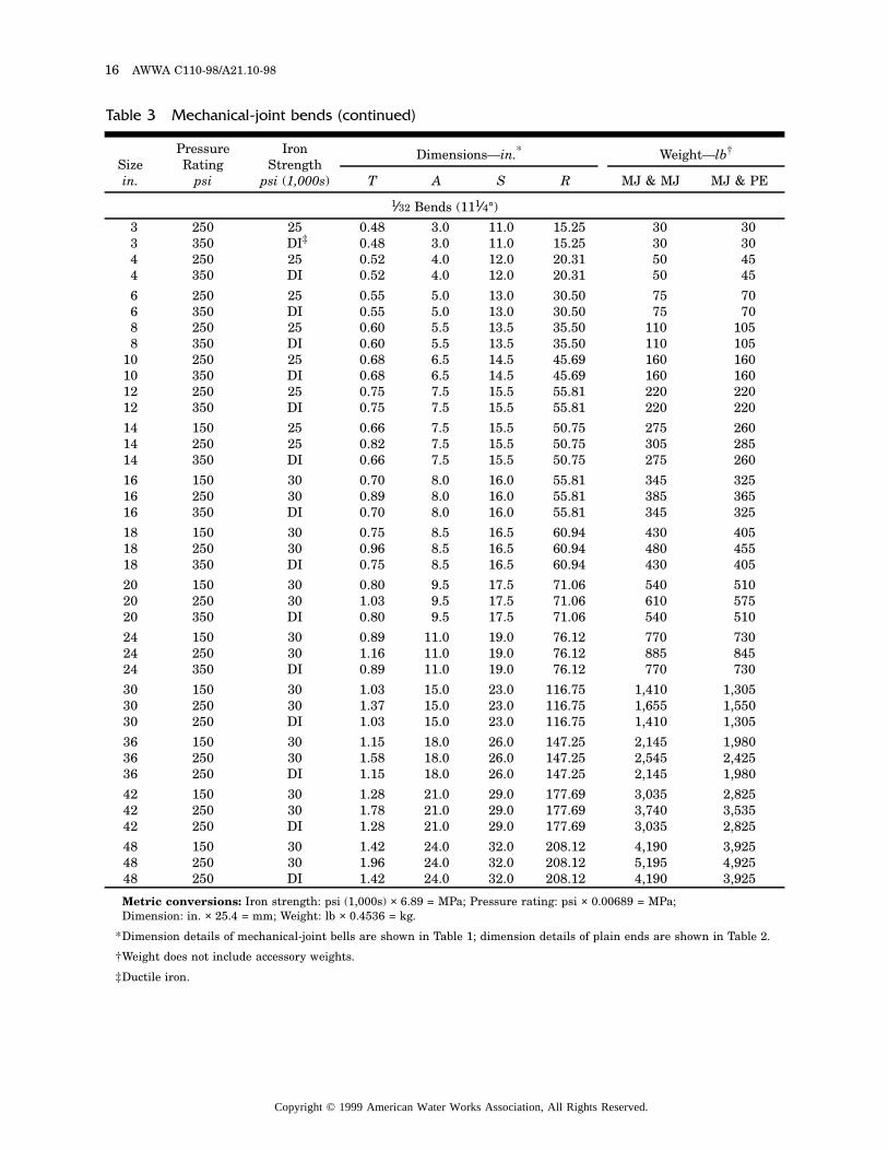
Table 3 Mechanical-joint bends (continued)
Sizein.
Pressure Rating
psi
Iron Strength
psi (1,000s)
Dimensions—in.* Weight—lb†
T A S R MJ & MJ MJ & PE
1⁄8 Bends (45°)
3 250 25 0.48 3.0 11.0 3.62 30 303 350 DI‡ 0.48 3.0 11.0 3.62 30 304 250 25 0.52 4.0 12.0 4.81 50 454 350 DI 0.52 4.0 12.0 4.81 50 45
6 250 25 0.55 5.0 13.0 7.25 75 706 350 DI 0.55 5.0 13.0 7.25 75 708 250 25 0.60 5.5 13.5 8.44 110 1058 350 DI 0.60 5.5 13.5 8.44 110 105
10 250 25 0.68 6.5 14.5 10.88 155 15510 350 DI 0.68 6.5 14.5 10.88 155 15512 250 25 0.75 7.5 15.5 13.25 215 21512 350 DI 0.75 7.5 15.5 13.25 215 215
14 150 25 0.66 7.5 15.5 12.06 270 25514 250 25 0.82 7.5 15.5 12.06 300 28014 350 DI 0.66 7.5 15.5 12.06 270 255
16 150 30 0.70 8.0 16.0 13.25 340 32016 250 30 0.89 8.0 16.0 13.25 380 36016 350 DI 0.70 8.0 16.0 13.25 340 320
18 150 30 0.75 8.5 16.5 14.50 420 39518 250 30 0.96 8.5 16.5 14.50 470 44518 350 DI 0.75 8.5 16.5 14.50 420 395
20 150 30 0.80 9.5 17.5 16.88 530 50020 250 30 1.03 9.5 17.5 16.88 595 56520 350 DI 0.80 9.5 17.5 16.88 530 500
24 150 30 0.89 11.0 19.0 18.12 755 71524 250 30 1.16 11.0 19.0 18.12 865 82524 350 DI 0.89 11.0 19.0 18.12 755 715
30 150 30 1.03 15.0 23.0 27.75 1,380 1,27530 250 30 1.37 15.0 23.0 27.75 1,620 1,51030 250 DI 1.03 15.0 23.0 27.75 1,380 1,275
36 150 30 1.15 18.0 26.0 35.00 2,095 1,93036 250 30 1.58 18.0 26.0 35.00 2,525 2,36036 250 DI 1.15 18.0 26.0 35.00 2,095 1,930
42 150 30 1.28 21.0 29.0 42.25 2,955 2,74542 250 30 1.78 21.0 29.0 42.25 3,635 3,42542 250 DI 1.28 21.0 29.0 42.25 2,955 2,745
48 150 30 1.42 24.0 32.0 49.50 4,080 3,81548 250 30 1.96 24.0 32.0 49.50 5,040 4,77048 250 DI 1.42 24.0 32.0 49.50 4,080 3,815
Table continued next page.
Copyright © 1999 American Water Works Association, All Rights Reserved.
DUCTILE-IRON AND GRAY-IRON FITTINGS FOR WATER 15
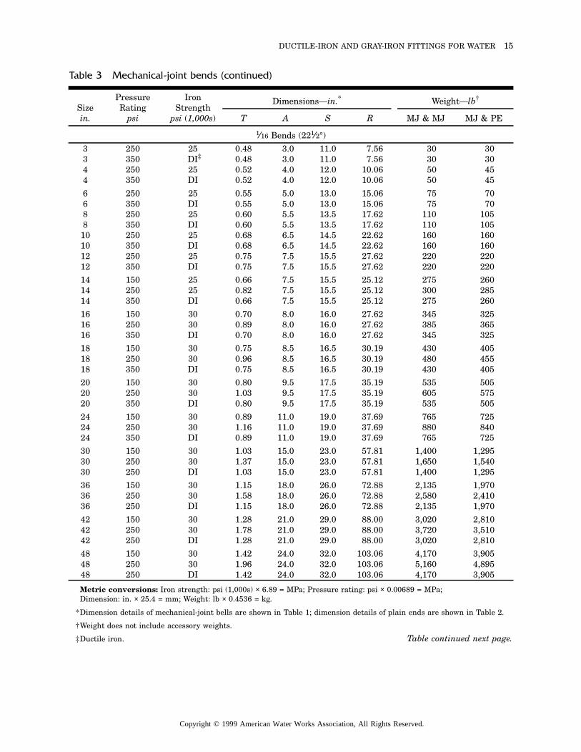
Metric conversions: Iron strength: psi (1,000s) × 6.89 = MPa; Pressure rating: psi × 0.00689 = MPa; Dimension: in. × 25.4 = mm; Weight: lb × 0.4536 = kg.
*Dimension details of mechanical-joint bells are shown in Table 1; dimension details of plain ends are shown in Table 2.
†Weight does not include accessory weights.
‡Ductile iron.
Table 3 Mechanical-joint bends (continued)
Sizein.
Pressure Rating
psi
Iron Strength
psi (1,000s)
Dimensions—in.* Weight—lb†
T A S R MJ & MJ MJ & PE
1⁄16 Bends (221⁄2°)
3 250 25 0.48 3.0 11.0 7.56 30 303 350 DI‡ 0.48 3.0 11.0 7.56 30 304 250 25 0.52 4.0 12.0 10.06 50 454 350 DI 0.52 4.0 12.0 10.06 50 45
6 250 25 0.55 5.0 13.0 15.06 75 706 350 DI 0.55 5.0 13.0 15.06 75 708 250 25 0.60 5.5 13.5 17.62 110 1058 350 DI 0.60 5.5 13.5 17.62 110 105
10 250 25 0.68 6.5 14.5 22.62 160 16010 350 DI 0.68 6.5 14.5 22.62 160 16012 250 25 0.75 7.5 15.5 27.62 220 22012 350 DI 0.75 7.5 15.5 27.62 220 220
14 150 25 0.66 7.5 15.5 25.12 275 26014 250 25 0.82 7.5 15.5 25.12 300 28514 350 DI 0.66 7.5 15.5 25.12 275 260
16 150 30 0.70 8.0 16.0 27.62 345 32516 250 30 0.89 8.0 16.0 27.62 385 36516 350 DI 0.70 8.0 16.0 27.62 345 325
18 150 30 0.75 8.5 16.5 30.19 430 40518 250 30 0.96 8.5 16.5 30.19 480 45518 350 DI 0.75 8.5 16.5 30.19 430 405
20 150 30 0.80 9.5 17.5 35.19 535 50520 250 30 1.03 9.5 17.5 35.19 605 57520 350 DI 0.80 9.5 17.5 35.19 535 505
24 150 30 0.89 11.0 19.0 37.69 765 72524 250 30 1.16 11.0 19.0 37.69 880 84024 350 DI 0.89 11.0 19.0 37.69 765 725
30 150 30 1.03 15.0 23.0 57.81 1,400 1,29530 250 30 1.37 15.0 23.0 57.81 1,650 1,54030 250 DI 1.03 15.0 23.0 57.81 1,400 1,295
36 150 30 1.15 18.0 26.0 72.88 2,135 1,97036 250 30 1.58 18.0 26.0 72.88 2,580 2,41036 250 DI 1.15 18.0 26.0 72.88 2,135 1,970
42 150 30 1.28 21.0 29.0 88.00 3,020 2,81042 250 30 1.78 21.0 29.0 88.00 3,720 3,51042 250 DI 1.28 21.0 29.0 88.00 3,020 2,810
48 150 30 1.42 24.0 32.0 103.06 4,170 3,90548 250 30 1.96 24.0 32.0 103.06 5,160 4,89548 250 DI 1.42 24.0 32.0 103.06 4,170 3,905
Table continued next page.
Copyright © 1999 American Water Works Association, All Rights Reserved.
16 AWWA C110-98/A21.10-98
Metric conversions: Iron strength: psi (1,000s) × 6.89 = MPa; Pressure rating: psi × 0.00689 = MPa; Dimension: in. × 25.4 = mm; Weight: lb × 0.4536 = kg.
*Dimension details of mechanical-joint bells are shown in Table 1; dimension details of plain ends are shown in Table 2.
†Weight does not include accessory weights.
‡Ductile iron.
Table 3 Mechanical-joint bends (continued)
Sizein.
Pressure Rating
psi
Iron Strength
psi (1,000s)
Dimensions—in.* Weight—lb†
T A S R MJ & MJ MJ & PE
1⁄32 Bends (111⁄4°)
3 250 25 0.48 3.0 11.0 15.25 30 303 350 DI‡ 0.48 3.0 11.0 15.25 30 304 250 25 0.52 4.0 12.0 20.31 50 454 350 DI 0.52 4.0 12.0 20.31 50 45
6 250 25 0.55 5.0 13.0 30.50 75 706 350 DI 0.55 5.0 13.0 30.50 75 708 250 25 0.60 5.5 13.5 35.50 110 1058 350 DI 0.60 5.5 13.5 35.50 110 105
10 250 25 0.68 6.5 14.5 45.69 160 16010 350 DI 0.68 6.5 14.5 45.69 160 16012 250 25 0.75 7.5 15.5 55.81 220 22012 350 DI 0.75 7.5 15.5 55.81 220 220
14 150 25 0.66 7.5 15.5 50.75 275 26014 250 25 0.82 7.5 15.5 50.75 305 28514 350 DI 0.66 7.5 15.5 50.75 275 260
16 150 30 0.70 8.0 16.0 55.81 345 32516 250 30 0.89 8.0 16.0 55.81 385 36516 350 DI 0.70 8.0 16.0 55.81 345 325
18 150 30 0.75 8.5 16.5 60.94 430 40518 250 30 0.96 8.5 16.5 60.94 480 45518 350 DI 0.75 8.5 16.5 60.94 430 405
20 150 30 0.80 9.5 17.5 71.06 540 51020 250 30 1.03 9.5 17.5 71.06 610 57520 350 DI 0.80 9.5 17.5 71.06 540 510
24 150 30 0.89 11.0 19.0 76.12 770 73024 250 30 1.16 11.0 19.0 76.12 885 84524 350 DI 0.89 11.0 19.0 76.12 770 730
30 150 30 1.03 15.0 23.0 116.75 1,410 1,30530 250 30 1.37 15.0 23.0 116.75 1,655 1,55030 250 DI 1.03 15.0 23.0 116.75 1,410 1,305
36 150 30 1.15 18.0 26.0 147.25 2,145 1,98036 250 30 1.58 18.0 26.0 147.25 2,545 2,42536 250 DI 1.15 18.0 26.0 147.25 2,145 1,980
42 150 30 1.28 21.0 29.0 177.69 3,035 2,82542 250 30 1.78 21.0 29.0 177.69 3,740 3,53542 250 DI 1.28 21.0 29.0 177.69 3,035 2,825
48 150 30 1.42 24.0 32.0 208.12 4,190 3,92548 250 30 1.96 24.0 32.0 208.12 5,195 4,92548 250 DI 1.42 24.0 32.0 208.12 4,190 3,925
Copyright © 1999 American Water Works Association, All Rights Reserved.
DUCTILE-IRON AND GRAY-IRON FITTINGS FOR WATER 17
All MJ
Tees
T T1
H H
JMJ, PE, and MJ
Crosses
MJ, PE, MJ, and MJ
T T1
H S
S
J
All MJ
T T1
H H
JJ
T T1
H
JJ
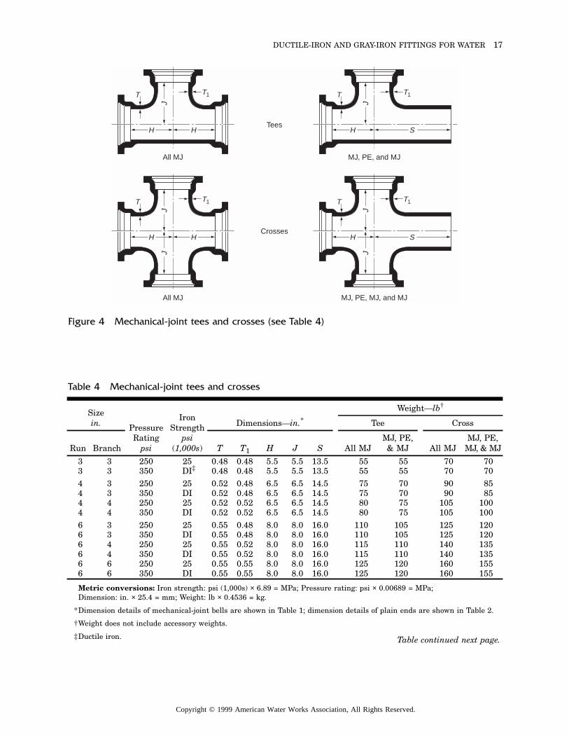
Figure 4 Mechanical-joint tees and crosses (see Table 4)
Metric conversions: Iron strength: psi (1,000s) × 6.89 = MPa; Pressure rating: psi × 0.00689 = MPa; Dimension: in. × 25.4 = mm; Weight: lb × 0.4536 = kg.
*Dimension details of mechanical-joint bells are shown in Table 1; dimension details of plain ends are shown in Table 2.
†Weight does not include accessory weights.
‡Ductile iron.
Table 4 Mechanical-joint tees and crosses
Sizein. Pressure
Ratingpsi
Iron Strength
psi (1,000s)
Dimensions—in.*Weight—lb†
Tee Cross
Run Branch T T1 H J S All MJMJ, PE, & MJ All MJ
MJ, PE, MJ, & MJ
3 3 250 25 0.48 0.48 5.5 5.5 13.5 55 55 70 703 3 350 DI‡ 0.48 0.48 5.5 5.5 13.5 55 55 70 704 3 250 25 0.52 0.48 6.5 6.5 14.5 75 70 90 854 3 350 DI 0.52 0.48 6.5 6.5 14.5 75 70 90 854 4 250 25 0.52 0.52 6.5 6.5 14.5 80 75 105 1004 4 350 DI 0.52 0.52 6.5 6.5 14.5 80 75 105 1006 3 250 25 0.55 0.48 8.0 8.0 16.0 110 105 125 1206 3 350 DI 0.55 0.48 8.0 8.0 16.0 110 105 125 1206 4 250 25 0.55 0.52 8.0 8.0 16.0 115 110 140 1356 4 350 DI 0.55 0.52 8.0 8.0 16.0 115 110 140 1356 6 250 25 0.55 0.55 8.0 8.0 16.0 125 120 160 1556 6 350 DI 0.55 0.55 8.0 8.0 16.0 125 120 160 155
Table continued next page.
Copyright © 1999 American Water Works Association, All Rights Reserved.
18 AWWA C110-98/A21.10-98
Metric conversions: Iron strength: psi (1,000s) × 6.89 = MPa; Pressure rating: psi × 0.00689 = MPa; Dimension: in. × 25.4 = mm; Weight: lb × 0.4536 = kg.
*Dimension details of mechanical-joint bells are shown in Table 1; dimension details of plain ends are shown in Table 2.
†Weight does not include accessory weights.
‡Ductile iron.
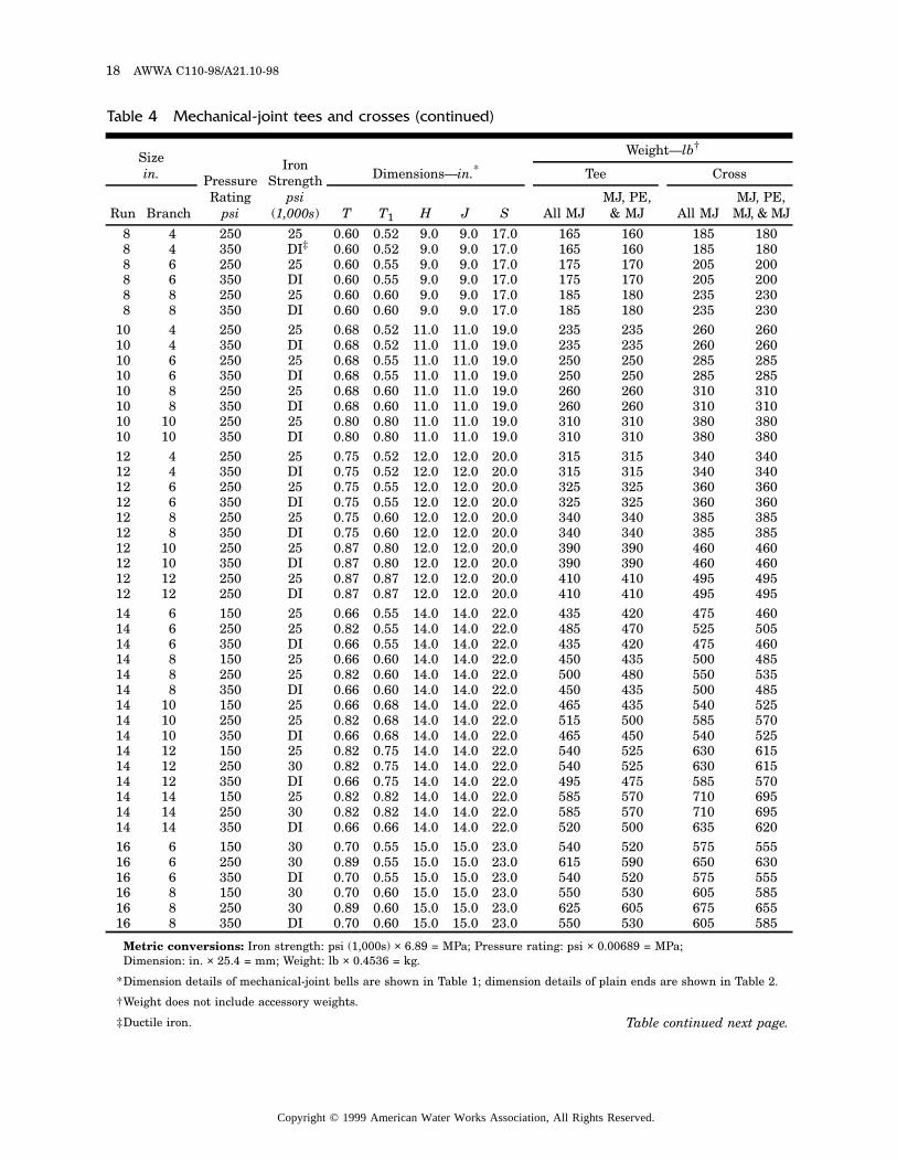
Table 4 Mechanical-joint tees and crosses (continued)
Sizein. Pressure
Ratingpsi
Iron Strength
psi (1,000s)
Dimensions—in.*Weight—lb†
Tee Cross
Run Branch T T1 H J S All MJMJ, PE, & MJ All MJ
MJ, PE, MJ, & MJ
8 4 250 25 0.60 0.52 9.0 9.0 17.0 165 160 185 1808 4 350 DI‡ 0.60 0.52 9.0 9.0 17.0 165 160 185 1808 6 250 25 0.60 0.55 9.0 9.0 17.0 175 170 205 2008 6 350 DI 0.60 0.55 9.0 9.0 17.0 175 170 205 2008 8 250 25 0.60 0.60 9.0 9.0 17.0 185 180 235 2308 8 350 DI 0.60 0.60 9.0 9.0 17.0 185 180 235 230
10 4 250 25 0.68 0.52 11.0 11.0 19.0 235 235 260 26010 4 350 DI 0.68 0.52 11.0 11.0 19.0 235 235 260 26010 6 250 25 0.68 0.55 11.0 11.0 19.0 250 250 285 28510 6 350 DI 0.68 0.55 11.0 11.0 19.0 250 250 285 28510 8 250 25 0.68 0.60 11.0 11.0 19.0 260 260 310 31010 8 350 DI 0.68 0.60 11.0 11.0 19.0 260 260 310 31010 10 250 25 0.80 0.80 11.0 11.0 19.0 310 310 380 38010 10 350 DI 0.80 0.80 11.0 11.0 19.0 310 310 380 38012 4 250 25 0.75 0.52 12.0 12.0 20.0 315 315 340 34012 4 350 DI 0.75 0.52 12.0 12.0 20.0 315 315 340 34012 6 250 25 0.75 0.55 12.0 12.0 20.0 325 325 360 36012 6 350 DI 0.75 0.55 12.0 12.0 20.0 325 325 360 36012 8 250 25 0.75 0.60 12.0 12.0 20.0 340 340 385 38512 8 350 DI 0.75 0.60 12.0 12.0 20.0 340 340 385 38512 10 250 25 0.87 0.80 12.0 12.0 20.0 390 390 460 46012 10 350 DI 0.87 0.80 12.0 12.0 20.0 390 390 460 46012 12 250 25 0.87 0.87 12.0 12.0 20.0 410 410 495 49512 12 250 DI 0.87 0.87 12.0 12.0 20.0 410 410 495 49514 6 150 25 0.66 0.55 14.0 14.0 22.0 435 420 475 46014 6 250 25 0.82 0.55 14.0 14.0 22.0 485 470 525 50514 6 350 DI 0.66 0.55 14.0 14.0 22.0 435 420 475 46014 8 150 25 0.66 0.60 14.0 14.0 22.0 450 435 500 48514 8 250 25 0.82 0.60 14.0 14.0 22.0 500 480 550 53514 8 350 DI 0.66 0.60 14.0 14.0 22.0 450 435 500 48514 10 150 25 0.66 0.68 14.0 14.0 22.0 465 435 540 52514 10 250 25 0.82 0.68 14.0 14.0 22.0 515 500 585 57014 10 350 DI 0.66 0.68 14.0 14.0 22.0 465 450 540 52514 12 150 25 0.82 0.75 14.0 14.0 22.0 540 525 630 61514 12 250 30 0.82 0.75 14.0 14.0 22.0 540 525 630 61514 12 350 DI 0.66 0.75 14.0 14.0 22.0 495 475 585 57014 14 150 25 0.82 0.82 14.0 14.0 22.0 585 570 710 69514 14 250 30 0.82 0.82 14.0 14.0 22.0 585 570 710 69514 14 350 DI 0.66 0.66 14.0 14.0 22.0 520 500 635 62016 6 150 30 0.70 0.55 15.0 15.0 23.0 540 520 575 55516 6 250 30 0.89 0.55 15.0 15.0 23.0 615 590 650 63016 6 350 DI 0.70 0.55 15.0 15.0 23.0 540 520 575 55516 8 150 30 0.70 0.60 15.0 15.0 23.0 550 530 605 58516 8 250 30 0.89 0.60 15.0 15.0 23.0 625 605 675 65516 8 350 DI 0.70 0.60 15.0 15.0 23.0 550 530 605 585
Table continued next page.
Copyright © 1999 American Water Works Association, All Rights Reserved.
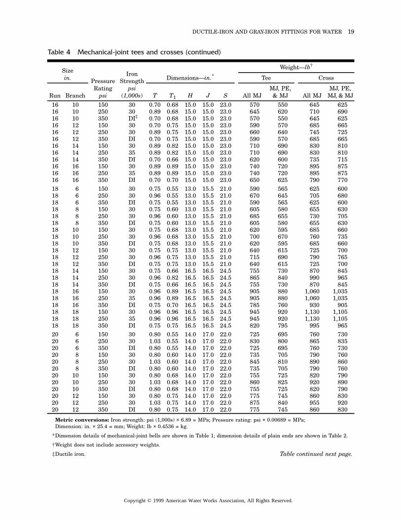
DUCTILE-IRON AND GRAY-IRON FITTINGS FOR WATER 19
Metric conversions: Iron strength: psi (1,000s) × 6.89 = MPa; Pressure rating: psi × 0.00689 = MPa; Dimension: in. × 25.4 = mm; Weight: lb × 0.4536 = kg.
*Dimension details of mechanical-joint bells are shown in Table 1; dimension details of plain ends are shown in Table 2.
†Weight does not include accessory weights.
‡Ductile iron.
Table 4 Mechanical-joint tees and crosses (continued)
Sizein. Pressure
Ratingpsi
Iron Strength
psi (1,000s)
Dimensions—in.*Weight—lb†
Tee Cross
Run Branch T T1 H J S All MJMJ, PE, & MJ All MJ
MJ, PE, MJ, & MJ
16 10 150 30 0.70 0.68 15.0 15.0 23.0 570 550 645 62516 10 250 30 0.89 0.68 15.0 15.0 23.0 645 620 710 69016 10 350 DI‡ 0.70 0.68 15.0 15.0 23.0 570 550 645 62516 12 150 30 0.70 0.75 15.0 15.0 23.0 590 570 685 66516 12 250 30 0.89 0.75 15.0 15.0 23.0 660 640 745 72516 12 350 DI 0.70 0.75 15.0 15.0 23.0 590 570 685 66516 14 150 30 0.89 0.82 15.0 15.0 23.0 710 690 830 81016 14 250 35 0.89 0.82 15.0 15.0 23.0 710 690 830 81016 14 350 DI 0.70 0.66 15.0 15.0 23.0 620 600 735 71516 16 150 30 0.89 0.89 15.0 15.0 23.0 740 720 895 87516 16 250 35 0.89 0.89 15.0 15.0 23.0 740 720 895 87516 16 350 DI 0.70 0.70 15.0 15.0 23.0 650 625 790 77018 6 150 30 0.75 0.55 13.0 15.5 21.0 590 565 625 60018 6 250 30 0.96 0.55 13.0 15.5 21.0 670 645 705 68018 6 350 DI 0.75 0.55 13.0 15.5 21.0 590 565 625 60018 8 150 30 0.75 0.60 13.0 15.5 21.0 605 580 655 63018 8 250 30 0.96 0.60 13.0 15.5 21.0 685 655 730 70518 8 350 DI 0.75 0.60 13.0 15.5 21.0 605 580 655 63018 10 150 30 0.75 0.68 13.0 15.5 21.0 620 595 685 66018 10 250 30 0.96 0.68 13.0 15.5 21.0 700 670 760 73518 10 350 DI 0.75 0.68 13.0 15.5 21.0 620 595 685 66018 12 150 30 0.75 0.75 13.0 15.5 21.0 640 615 725 70018 12 250 30 0.96 0.75 13.0 15.5 21.0 715 690 790 76518 12 350 DI 0.75 0.75 13.0 15.5 21.0 640 615 725 70018 14 150 30 0.75 0.66 16.5 16.5 24.5 755 730 870 84518 14 250 30 0.96 0.82 16.5 16.5 24.5 865 840 990 96518 14 350 DI 0.75 0.66 16.5 16.5 24.5 755 730 870 84518 16 150 30 0.96 0.89 16.5 16.5 24.5 905 880 1,060 1,03518 16 250 35 0.96 0.89 16.5 16.5 24.5 905 880 1,060 1,03518 16 350 DI 0.75 0.70 16.5 16.5 24.5 785 760 930 90518 18 150 30 0.96 0.96 16.5 16.5 24.5 945 920 1,130 1,10518 18 250 35 0.96 0.96 16.5 16.5 24.5 945 920 1,130 1,10518 18 350 DI 0.75 0.75 16.5 16.5 24.5 820 795 995 96520 6 150 30 0.80 0.55 14.0 17.0 22.0 725 695 760 73020 6 250 30 1.03 0.55 14.0 17.0 22.0 830 800 865 83520 6 350 DI 0.80 0.55 14.0 17.0 22.0 725 695 760 73020 8 150 30 0.80 0.60 14.0 17.0 22.0 735 705 790 76020 8 250 30 1.03 0.60 14.0 17.0 22.0 845 810 890 86020 8 350 DI 0.80 0.60 14.0 17.0 22.0 735 705 790 76020 10 150 30 0.80 0.68 14.0 17.0 22.0 755 725 820 79020 10 250 30 1.03 0.68 14.0 17.0 22.0 860 825 920 89020 10 350 DI 0.80 0.68 14.0 17.0 22.0 755 725 820 79020 12 150 30 0.80 0.75 14.0 17.0 22.0 775 745 860 83020 12 250 30 1.03 0.75 14.0 17.0 22.0 875 840 955 92020 12 350 DI 0.80 0.75 14.0 17.0 22.0 775 745 860 830
Table continued next page.
Copyright © 1999 American Water Works Association, All Rights Reserved.
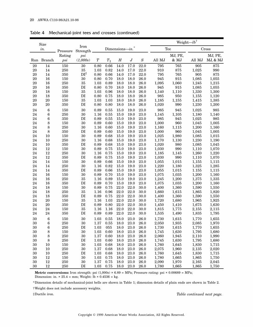
20 AWWA C110-98/A21.10-98
Metric conversions: Iron strength: psi (1,000s) × 6.89 = MPa; Pressure rating: psi × 0.00689 = MPa; Dimension: in. × 25.4 = mm; Weight: lb × 0.4536 = kg.
*Dimension details of mechanical-joint bells are shown in Table 1; dimension details of plain ends are shown in Table 2.
†Weight does not include accessory weights.
‡Ductile iron.
Table 4 Mechanical-joint tees and crosses (continued)
Sizein. Pressure
Ratingpsi
Iron Strength
psi (1,000s)
Dimensions—in.*Weight—lb†
Tee Cross
Run Branch T T1 H J S All MJMJ, PE, & MJ All MJ
MJ, PE, MJ, & MJ
20 14 150 30 0.80 0.66 14.0 17.0 22.0 795 765 905 87520 14 250 35 1.03 0.82 14.0 17.0 22.0 910 875 1,025 99020 14 350 DI‡ 0.80 0.66 14.0 17.0 22.0 795 765 905 87520 16 150 30 0.80 0.70 18.0 18.0 26.0 945 915 1,085 1,05520 16 250 35 1.03 0.89 18.0 18.0 26.0 1,095 1,060 1,245 1,21520 16 350 DI 0.80 0.70 18.0 18.0 26.0 945 915 1,085 1,05520 18 150 35 1.03 0.96 18.0 18.0 26.0 1,140 1,110 1,330 1,30020 18 350 DI 0.80 0.75 18.0 18.0 26.0 985 950 1,155 1,12020 20 150 35 1.03 1.03 18.0 18.0 26.0 1,185 1,155 1,415 1,38520 20 350 DI 0.80 0.80 18.0 18.0 26.0 1,020 990 1,230 1,20024 6 150 30 0.89 0.55 15.0 19.0 23.0 985 945 1,025 98524 6 250 30 1.16 0.55 15.0 19.0 23.0 1,145 1,105 1,180 1,14024 6 350 DI 0.89 0.55 15.0 19.0 23.0 985 945 1,025 98524 8 150 30 0.89 0.60 15.0 19.0 23.0 1,000 960 1,045 1,00524 8 250 30 1.16 0.60 15.0 19.0 23.0 1,160 1,115 1,200 1,16024 8 350 DI 0.89 0.60 15.0 19.0 23.0 1,000 960 1,045 1,00524 10 150 30 0.89 0.68 15.0 19.0 23.0 1,025 1,980 1,085 1,01524 10 250 30 1.16 0.68 15.0 19.0 23.0 1,170 1,130 1,230 1,19024 10 350 DI 0.89 0.68 15.0 19.0 23.0 1,020 980 1,085 1,04524 12 150 30 0.89 0.75 15.0 19.0 23.0 1,030 990 1,110 1,07024 12 250 30 1.16 0.75 15.0 19.0 23.0 1,185 1,145 1,260 1,22024 12 350 DI 0.89 0.75 15.0 19.0 23.0 1,030 990 1,110 1,07024 14 150 30 0.89 0.66 15.0 19.0 23.0 1,055 1,015 1,155 1,11524 14 250 30 1.16 0.82 15.0 19.0 23.0 1,220 1,180 1,325 1,28524 14 350 DI 0.89 0.66 15.0 19.0 23.0 1,055 1,015 1.155 1,11524 16 150 30 0.89 0.70 15.0 19.0 23.0 1,075 1,035 1,200 1,16024 16 250 35 1.16 0.89 15.0 19.0 23.0 1,245 1,200 1,375 1,33524 16 350 DI 0.89 0.70 15.0 19.0 23.0 1,075 1,035 1,200 1,16024 18 150 30 0.89 0.75 22.0 22.0 30.0 1,400 1,360 1,590 1,55024 18 250 35 1.16 0.96 22.0 22.0 30.0 1,660 1,615 1,865 1,82024 18 350 DI 0.89 0.75 22.0 22.0 30.0 1,400 1,360 1,590 1,55024 20 150 35 1.16 1.03 22.0 22.0 30.0 1,720 1,680 1,965 1,92524 20 350 DI 0.89 0.80 22.0 22.0 30.0 1,450 1,410 1,675 1,63024 24 150 35 1.16 1.16 22.0 22.0 30.0 1,815 1,775 2,155 2,11524 24 350 DI 0.89 0.89 22.0 22.0 30.0 1,535 1,490 1,835 1,79530 6 150 30 1.03 0.55 18.0 23.0 26.0 1,730 1,615 1,770 1,65530 6 250 30 1.37 0.55 18.0 23.0 26.0 2,050 1,935 2,085 1,97030 6 250 DI 1.03 055 18.0 23.0 26.0 1,730 1,615 1,770 1,65530 8 150 30 1.03 0.60 18.0 23.0 26.0 1,745 1,630 1,795 1,68030 8 250 30 1.37 0.60 18.0 23.0 26.0 2,060 1,945 2,110 1,99030 8 250 DI 1.03 0.60 18.0 23.0 26.0 1,745 1,630 1,795 1,68030 10 150 30 1.03 0.68 18.0 23.0 26.0 1,760 1,645 1,830 1,71530 10 250 30 1.37 0.68 18.0 23.0 26.0 2,075 1,960 2,135 2,02030 10 250 DI 1.03 0.68 18.0 23.0 26.0 1,760 1,645 1,830 1,71530 12 150 30 1.03 0.75 18.0 23.0 26.0 1,780 1,665 1,865 1,75030 12 250 30 1.37 0.75 18.0 23.0 26.0 2,090 1,970 2,165 2,04530 12 250 DI 1.03 0.75 18.0 23.0 26.0 1,780 1,665 1,865 1,750
Table continued next page.
Copyright © 1999 American Water Works Association, All Rights Reserved.
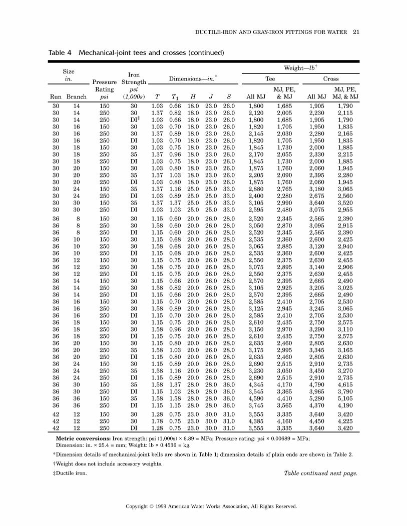
DUCTILE-IRON AND GRAY-IRON FITTINGS FOR WATER 21
Metric conversions: Iron strength: psi (1,000s) × 6.89 = MPa; Pressure rating: psi × 0.00689 = MPa; Dimension: in. × 25.4 = mm; Weight: lb × 0.4536 = kg.
*Dimension details of mechanical-joint bells are shown in Table 1; dimension details of plain ends are shown in Table 2.
†Weight does not include accessory weights.
‡Ductile iron.
Table 4 Mechanical-joint tees and crosses (continued)
Sizein. Pressure
Ratingpsi
Iron Strength
psi (1,000s)
Dimensions—in.*Weight—lb†
Tee Cross
Run Branch T T1 H J S All MJMJ, PE, & MJ All MJ
MJ, PE, MJ, & MJ
30 14 150 30 1.03 0.66 18.0 23.0 26.0 1,800 1,685 1,905 1,79030 14 250 30 1.37 0.82 18.0 23.0 26.0 2,120 2,005 2,230 2,11530 14 250 DI‡ 1.03 0.66 18.0 23.0 26.0 1,800 1,685 1,905 1,79030 16 150 30 1.03 0.70 18.0 23.0 26.0 1,820 1,705 1,950 1,83530 16 250 30 1.37 0.89 18.0 23.0 26.0 2,145 2,030 2,280 2,16530 16 250 DI 1.03 0.70 18.0 23.0 26.0 1,820 1,705 1,950 1,83530 18 150 30 1.03 0.75 18.0 23.0 26.0 1,845 1,730 2,000 1,88530 18 250 35 1.37 0.96 18.0 23.0 26.0 2,170 2,055 2,330 2,21530 18 250 DI 1.03 0.75 18.0 23.0 26.0 1,845 1,730 2,000 1,88530 20 150 30 1.03 0.80 18.0 23.0 26.0 1,875 1,760 2,060 1,94530 20 250 35 1.37 1.03 18.0 23.0 26.0 2,205 2,090 2,395 2,28030 20 250 DI 1.03 0.80 18.0 23.0 26.0 1,875 1,760 2,060 1,94530 24 150 35 1.37 1.16 25.0 25.0 33.0 2,880 2,765 3,180 3,06530 24 250 DI 1.03 0.89 25.0 25.0 33.0 2,400 2,280 2,675 2,56030 30 150 35 1.37 1.37 25.0 25.0 33.0 3,105 2,990 3,640 3,52030 30 250 DI 1.03 1.03 25.0 25.0 33.0 2,595 2,480 3,075 2,95536 8 150 30 1.15 0.60 20.0 26.0 28.0 2,520 2,345 2,565 2,39036 8 250 30 1.58 0.60 20.0 26.0 28.0 3,050 2,870 3,095 2,91536 8 250 DI 1.15 0.60 20.0 26.0 28.0 2,520 2,345 2,565 2,39036 10 150 30 1.15 0.68 20.0 26.0 28.0 2,535 2,360 2,600 2,42536 10 250 30 1.58 0.68 20.0 26.0 28.0 3,065 2,885 3,120 2,94036 10 250 DI 1.15 0.68 20.0 26.0 28.0 2,535 2,360 2,600 2,42536 12 150 30 1.15 0.75 20.0 26.0 28.0 2,550 2,375 2,630 2,45536 12 250 30 1.58 0.75 20.0 26.0 28.0 3,075 2,895 3,140 2,90636 12 250 DI 1.15 0.75 20.0 26.0 28.0 2,550 2,375 2,630 2,45536 14 150 30 1.15 0.66 20.0 26.0 28.0 2,570 2,395 2,665 2,49036 14 250 30 1.58 0.82 20.0 26.0 28.0 3,105 2,925 3,205 3,02536 14 250 DI 1.15 0.66 20.0 26.0 28.0 2,570 2,395 2,665 2,49036 16 150 30 1.15 0.70 20.0 26.0 28.0 2,585 2,410 2,705 2,53036 16 250 30 1.58 0.89 20.0 26.0 28.0 3,125 2,945 3,245 3,06536 16 250 DI 1.15 0.70 20.0 26.0 28.0 2,585 2,410 2,705 2,53036 18 150 30 1.15 0.75 20.0 26.0 28.0 2,610 2,435 2,750 2,57536 18 250 30 1.58 0.96 20.0 26.0 28.0 3,150 2,970 3,290 3,11036 18 250 DI 1.15 0.75 20.0 26.0 28.0 2,610 2,435 2,750 2,57536 20 150 30 1.15 0.80 20.0 26.0 28.0 2,635 2,460 2,805 2,63036 20 250 35 1.58 1.03 20.0 26.0 28.0 3,175 2,995 3,345 3,16536 20 250 DI 1.15 0.80 20.0 26.0 28.0 2,635 2,460 2,805 2,63036 24 150 30 1.15 0.89 20.0 26.0 28.0 2,690 2,515 2,910 2,73536 24 250 35 1.58 1.16 20.0 26.0 28.0 3,230 3,050 3,450 3,27036 24 250 DI 1.15 0.89 20.0 26.0 28.0 2,690 2,515 2,910 2,73536 30 150 35 1.58 1.37 28.0 28.0 36.0 4,345 4,170 4,790 4,61536 30 250 DI 1.15 1.03 28.0 28.0 36.0 3,545 3,365 3,965 3,79036 36 150 35 1.58 1.58 28.0 28.0 36.0 4,590 4,410 5,280 5,10536 36 250 DI 1.15 1.15 28.0 28.0 36.0 3,745 3,565 4,370 4,19042 12 150 30 1.28 0.75 23.0 30.0 31.0 3,555 3,335 3,640 3,42042 12 250 30 1.78 0.75 23.0 30.0 31.0 4,385 4,160 4,450 4,22542 12 250 DI 1.28 0.75 23.0 30.0 31.0 3,555 3,335 3,640 3,420
Table continued next page.
Copyright © 1999 American Water Works Association, All Rights Reserved.
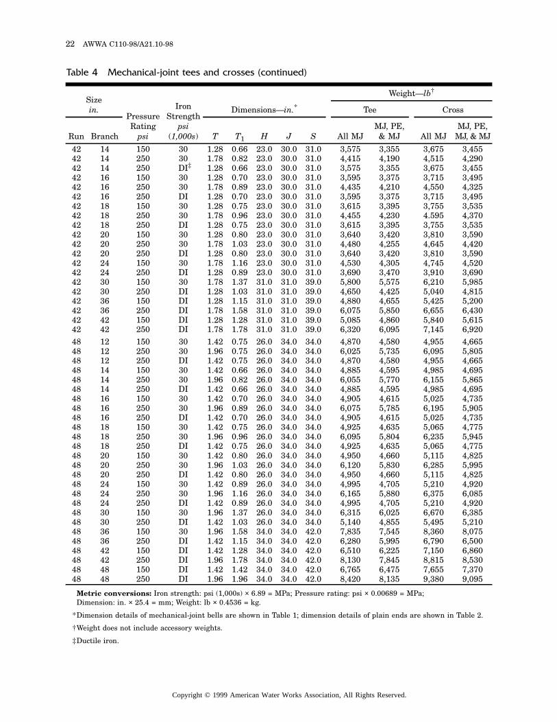
22 AWWA C110-98/A21.10-98
Metric conversions: Iron strength: psi (1,000s) × 6.89 = MPa; Pressure rating: psi × 0.00689 = MPa; Dimension: in. × 25.4 = mm; Weight: lb × 0.4536 = kg.
*Dimension details of mechanical-joint bells are shown in Table 1; dimension details of plain ends are shown in Table 2.
†Weight does not include accessory weights.
‡Ductile iron.
Table 4 Mechanical-joint tees and crosses (continued)
Sizein.
PressureRating
psi
Iron Strength
psi (1,000s)
Dimensions—in.*
Weight—lb†
Tee Cross
Run Branch T T1 H J S All MJMJ, PE, & MJ All MJ
MJ, PE, MJ, & MJ
42 14 150 30 1.28 0.66 23.0 30.0 31.0 3,575 3,355 3,675 3,45542 14 250 30 1.78 0.82 23.0 30.0 31.0 4,415 4,190 4,515 4,29042 14 250 DI‡ 1.28 0.66 23.0 30.0 31.0 3,575 3,355 3,675 3,45542 16 150 30 1.28 0.70 23.0 30.0 31.0 3,595 3,375 3,715 3,49542 16 250 30 1.78 0.89 23.0 30.0 31.0 4,435 4,210 4,550 4,32542 16 250 DI 1.28 0.70 23.0 30.0 31.0 3,595 3,375 3,715 3,49542 18 150 30 1.28 0.75 23.0 30.0 31.0 3,615 3,395 3,755 3,53542 18 250 30 1.78 0.96 23.0 30.0 31.0 4,455 4,230 4.595 4,37042 18 250 DI 1.28 0.75 23.0 30.0 31.0 3,615 3,395 3,755 3,53542 20 150 30 1.28 0.80 23.0 30.0 31.0 3,640 3,420 3,810 3,59042 20 250 30 1.78 1.03 23.0 30.0 31.0 4,480 4,255 4,645 4,42042 20 250 DI 1.28 0.80 23.0 30.0 31.0 3,640 3,420 3,810 3,59042 24 150 30 1.78 1.16 23.0 30.0 31.0 4,530 4,305 4,745 4,52042 24 250 DI 1.28 0.89 23.0 30.0 31.0 3,690 3,470 3,910 3,69042 30 150 30 1.78 1.37 31.0 31.0 39.0 5,800 5,575 6,210 5,98542 30 250 DI 1.28 1.03 31.0 31.0 39.0 4,650 4,425 5,040 4,81542 36 150 DI 1.28 1.15 31.0 31.0 39.0 4,880 4,655 5,425 5,20042 36 250 DI 1.78 1.58 31.0 31.0 39.0 6,075 5,850 6,655 6,43042 42 150 DI 1.28 1.28 31.0 31.0 39.0 5,085 4,860 5,840 5,61542 42 250 DI 1.78 1.78 31.0 31.0 39.0 6,320 6,095 7,145 6,92048 12 150 30 1.42 0.75 26.0 34.0 34.0 4,870 4,580 4,955 4,66548 12 250 30 1.96 0.75 26.0 34.0 34.0 6,025 5,735 6,095 5,80548 12 250 DI 1.42 0.75 26.0 34.0 34.0 4,870 4,580 4,955 4,66548 14 150 30 1.42 0.66 26.0 34.0 34.0 4,885 4,595 4,985 4,69548 14 250 30 1.96 0.82 26.0 34.0 34.0 6,055 5,770 6,155 5,86548 14 250 DI 1.42 0.66 26.0 34.0 34.0 4,885 4,595 4,985 4,69548 16 150 30 1.42 0.70 26.0 34.0 34.0 4,905 4,615 5,025 4,73548 16 250 30 1.96 0.89 26.0 34.0 34.0 6,075 5,785 6,195 5,90548 16 250 DI 1.42 0.70 26.0 34.0 34.0 4,905 4,615 5,025 4,73548 18 150 30 1.42 0.75 26.0 34.0 34.0 4,925 4,635 5,065 4,77548 18 250 30 1.96 0.96 26.0 34.0 34.0 6,095 5,804 6,235 5,94548 18 250 DI 1.42 0.75 26.0 34.0 34.0 4,925 4,635 5,065 4,77548 20 150 30 1.42 0.80 26.0 34.0 34.0 4,950 4,660 5,115 4,82548 20 250 30 1.96 1.03 26.0 34.0 34.0 6,120 5,830 6,285 5,99548 20 250 DI 1.42 0.80 26.0 34.0 34.0 4,950 4,660 5,115 4,82548 24 150 30 1.42 0.89 26.0 34.0 34.0 4,995 4,705 5,210 4,92048 24 250 30 1.96 1.16 26.0 34.0 34.0 6,165 5,880 6,375 6,08548 24 250 DI 1.42 0.89 26.0 34.0 34.0 4,995 4,705 5,210 4,92048 30 150 30 1.96 1.37 26.0 34.0 34.0 6,315 6,025 6,670 6,38548 30 250 DI 1.42 1.03 26.0 34.0 34.0 5,140 4,855 5,495 5,21048 36 150 30 1.96 1.58 34.0 34.0 42.0 7,835 7,545 8,360 8,07548 36 250 DI 1.42 1.15 34.0 34.0 42.0 6,280 5,995 6,790 6,50048 42 150 DI 1.42 1.28 34.0 34.0 42.0 6,510 6,225 7,150 6,86048 42 250 DI 1.96 1.78 34.0 34.0 42.0 8,130 7,845 8,815 8,53048 48 150 DI 1.42 1.42 34.0 34.0 42.0 6,765 6,475 7,655 7,37048 48 250 DI 1.96 1.96 34.0 34.0 42.0 8,420 8,135 9,380 9,095
Copyright © 1999 American Water Works Association, All Rights Reserved.
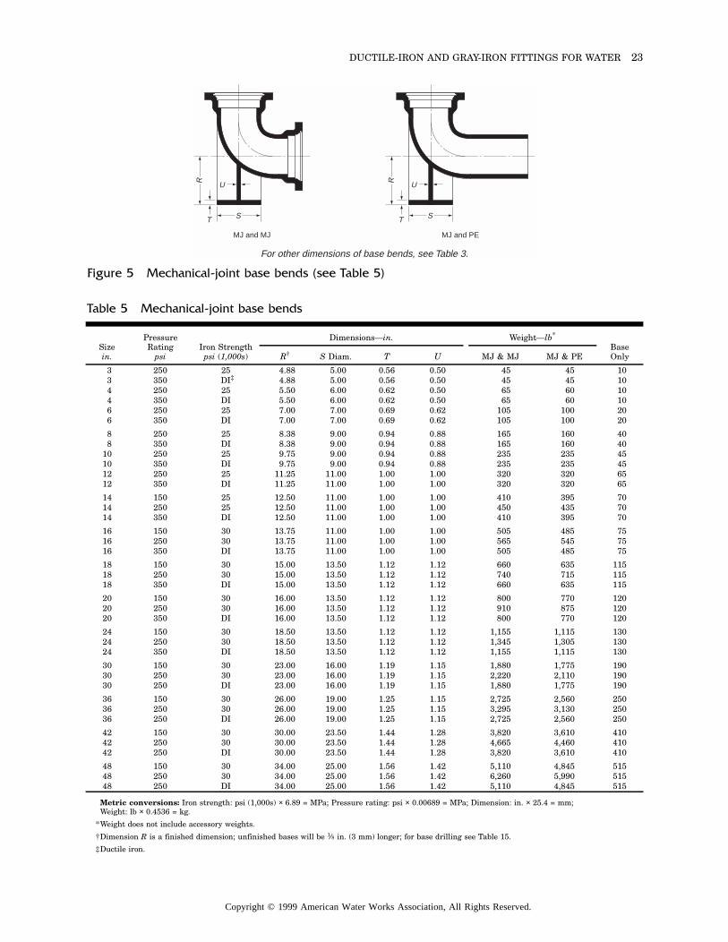
DUCTILE-IRON AND GRAY-IRON FITTINGS FOR WATER 23
For other dimensions of base bends, see Table 3.
MJ and MJ
S
U
T
R
MJ and PE
S
U
T
R
Figure 5 Mechanical-joint base bends (see Table 5)
Metric conversions: Iron strength: psi (1,000s) × 6.89 = MPa; Pressure rating: psi × 0.00689 = MPa; Dimension: in. × 25.4 = mm; Weight: lb × 0.4536 = kg.
*Weight does not include accessory weights.
†Dimension R is a finished dimension; unfinished bases will be 1⁄8 in. (3 mm) longer; for base drilling see Table 15.
‡Ductile iron.
Table 5 Mechanical-joint base bends
Sizein.
Pressure Rating
psiIron Strengthpsi (1,000s)
Dimensions—in. Weight—lb*
Base OnlyR† S Diam. T U MJ & MJ MJ & PE
3 250 25 4.88 5.00 0.56 0.50 45 45 103 350 DI‡ 4.88 5.00 0.56 0.50 45 45 104 250 25 5.50 6.00 0.62 0.50 65 60 104 350 DI 5.50 6.00 0.62 0.50 65 60 106 250 25 7.00 7.00 0.69 0.62 105 100 206 350 DI 7.00 7.00 0.69 0.62 105 100 20
8 250 25 8.38 9.00 0.94 0.88 165 160 408 350 DI 8.38 9.00 0.94 0.88 165 160 40
10 250 25 9.75 9.00 0.94 0.88 235 235 4510 350 DI 9.75 9.00 0.94 0.88 235 235 4512 250 25 11.25 11.00 1.00 1.00 320 320 6512 350 DI 11.25 11.00 1.00 1.00 320 320 65
14 150 25 12.50 11.00 1.00 1.00 410 395 7014 250 25 12.50 11.00 1.00 1.00 450 435 7014 350 DI 12.50 11.00 1.00 1.00 410 395 70
16 150 30 13.75 11.00 1.00 1.00 505 485 7516 250 30 13.75 11.00 1.00 1.00 565 545 7516 350 DI 13.75 11.00 1.00 1.00 505 485 75
18 150 30 15.00 13.50 1.12 1.12 660 635 11518 250 30 15.00 13.50 1.12 1.12 740 715 11518 350 DI 15.00 13.50 1.12 1.12 660 635 115
20 150 30 16.00 13.50 1.12 1.12 800 770 12020 250 30 16.00 13.50 1.12 1.12 910 875 12020 350 DI 16.00 13.50 1.12 1.12 800 770 120
24 150 30 18.50 13.50 1.12 1.12 1,155 1,115 13024 250 30 18.50 13.50 1.12 1.12 1,345 1,305 13024 350 DI 18.50 13.50 1.12 1.12 1,155 1,115 130
30 150 30 23.00 16.00 1.19 1.15 1,880 1,775 19030 250 30 23.00 16.00 1.19 1.15 2,220 2,110 19030 250 DI 23.00 16.00 1.19 1.15 1,880 1,775 190
36 150 30 26.00 19.00 1.25 1.15 2,725 2,560 25036 250 30 26.00 19.00 1.25 1.15 3,295 3,130 25036 250 DI 26.00 19.00 1.25 1.15 2,725 2,560 250
42 150 30 30.00 23.50 1.44 1.28 3,820 3,610 41042 250 30 30.00 23.50 1.44 1.28 4,665 4,460 41042 250 DI 30.00 23.50 1.44 1.28 3,820 3,610 410
48 150 30 34.00 25.00 1.56 1.42 5,110 4,845 51548 250 30 34.00 25.00 1.56 1.42 6,260 5,990 51548 250 DI 34.00 25.00 1.56 1.42 5,110 4,845 515
Copyright © 1999 American Water Works Association, All Rights Reserved.
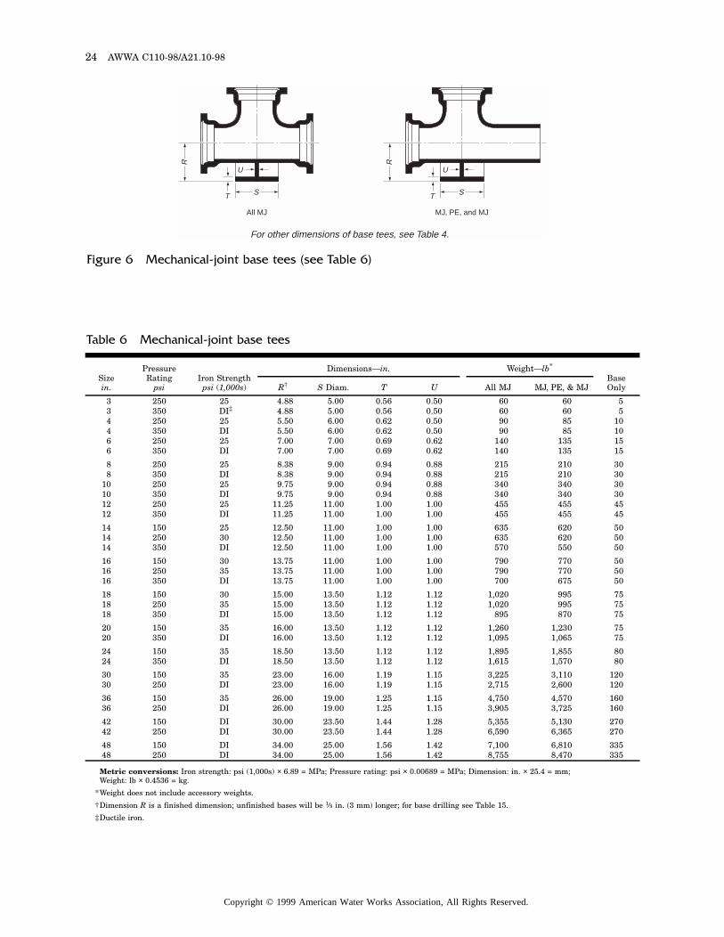
24 AWWA C110-98/A21.10-98
All MJ MJ, PE, and MJ
S
U
T
RS
U
T
R
For other dimensions of base tees, see Table 4.
Figure 6 Mechanical-joint base tees (see Table 6)
Metric conversions: Iron strength: psi (1,000s) × 6.89 = MPa; Pressure rating: psi × 0.00689 = MPa; Dimension: in. × 25.4 = mm; Weight: lb × 0.4536 = kg.
*Weight does not include accessory weights.
†Dimension R is a finished dimension; unfinished bases will be 1⁄8 in. (3 mm) longer; for base drilling see Table 15.
‡Ductile iron.
Table 6 Mechanical-joint base tees
Sizein.
Pressure Rating
psiIron Strength
psi (1,000s)
Dimensions—in. Weight—lb*
Base OnlyR† S Diam. T U All MJ MJ, PE, & MJ
3 250 25 4.88 5.00 0.56 0.50 60 60 53 350 DI‡ 4.88 5.00 0.56 0.50 60 60 54 250 25 5.50 6.00 0.62 0.50 90 85 104 350 DI 5.50 6.00 0.62 0.50 90 85 106 250 25 7.00 7.00 0.69 0.62 140 135 156 350 DI 7.00 7.00 0.69 0.62 140 135 15
8 250 25 8.38 9.00 0.94 0.88 215 210 308 350 DI 8.38 9.00 0.94 0.88 215 210 30
10 250 25 9.75 9.00 0.94 0.88 340 340 3010 350 DI 9.75 9.00 0.94 0.88 340 340 3012 250 25 11.25 11.00 1.00 1.00 455 455 4512 350 DI 11.25 11.00 1.00 1.00 455 455 45
14 150 25 12.50 11.00 1.00 1.00 635 620 5014 250 30 12.50 11.00 1.00 1.00 635 620 5014 350 DI 12.50 11.00 1.00 1.00 570 550 50
16 150 30 13.75 11.00 1.00 1.00 790 770 5016 250 35 13.75 11.00 1.00 1.00 790 770 5016 350 DI 13.75 11.00 1.00 1.00 700 675 50
18 150 30 15.00 13.50 1.12 1.12 1,020 995 7518 250 35 15.00 13.50 1.12 1.12 1,020 995 7518 350 DI 15.00 13.50 1.12 1.12 895 870 75
20 150 35 16.00 13.50 1.12 1.12 1,260 1,230 7520 350 DI 16.00 13.50 1.12 1.12 1,095 1,065 75
24 150 35 18.50 13.50 1.12 1.12 1,895 1,855 8024 350 DI 18.50 13.50 1.12 1.12 1,615 1,570 80
30 150 35 23.00 16.00 1.19 1.15 3,225 3,110 12030 250 DI 23.00 16.00 1.19 1.15 2,715 2,600 120
36 150 35 26.00 19.00 1.25 1.15 4,750 4,570 16036 250 DI 26.00 19.00 1.25 1.15 3,905 3,725 160
42 150 DI 30.00 23.50 1.44 1.28 5,355 5,130 27042 250 DI 30.00 23.50 1.44 1.28 6,590 6,365 270
48 150 DI 34.00 25.00 1.56 1.42 7,100 6,810 33548 250 DI 34.00 25.00 1.56 1.42 8,755 8,470 335
Copyright © 1999 American Water Works Association, All Rights Reserved.
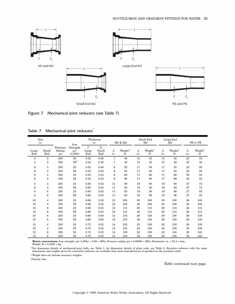
DUCTILE-IRON AND GRAY-IRON FITTINGS FOR WATER 25
MJ and MJ
L
T T1
Large-End MJ
Small-End MJ
L
T T1
L
T T1
PE and PE
L
T T1
Figure 7 Mechanical-joint reducers (see Table 7)
Metric conversions: Iron strength: psi (1,000s) × 6.89 = MPa; Pressure rating: psi × 0.00689 = MPa; Dimension: in. × 25.4 = mm; Weight: lb × 0.4536 = kg.
*For dimension details of mechanical-joint bells, see Table 1; for dimension details of plain ends, see Table 2. Eccentric reducers with the samedimensions and weights given for concentric reducers are available from most manufacturers if specified on the purchase order.
†Weight does not include accessory weights.
‡Ductile iron.
Table 7 Mechanical-joint reducers*
Sizein.
Pressure Rating
psi
Iron Strength
psi (1,000s)
Thicknessin. MJ & MJ
Small-EndMJ
Large-EndMJ PE to PE
Large End
Small End
TLarge End
T1Small End
Lin.
Weight†
lbL
in.Weight†
lbLin.
Weight†
lbLin.
Weight†
lb
4 3 250 25 0.52 0.48 7 40 15 35 15 40 23 354 3 350 DI‡ 0.52 0.48 7 40 15 35 15 40 23 35
6 3 250 25 0.55 0.48 9 55 17 50 17 55 25 506 3 350 DI 0.55 0.48 9 55 17 50 17 55 25 506 4 250 25 0.55 0.52 9 60 17 60 17 60 25 556 4 350 DI 0.55 0.52 9 60 17 60 17 60 25 55
8 4 250 25 0.60 0.52 11 80 19 80 19 80 27 758 4 350 DI 0.60 0.52 11 80 19 80 19 80 27 758 6 250 25 0.60 0.55 11 95 19 90 19 90 27 858 6 350 DI 0.60 0.55 11 95 19 90 19 90 27 85
10 4 250 25 0.68 0.52 12 105 20 100 20 100 28 10010 4 350 DI 0.68 0.52 12 105 20 100 20 100 28 10010 6 250 25 0.68 0.55 12 115 20 115 20 115 28 11510 6 350 DI 0.68 0.55 12 115 20 115 20 115 28 11510 8 250 25 0.68 0.60 12 135 20 130 20 130 28 13010 8 350 DI 0.68 0.60 12 135 20 130 20 130 28 130
12 4 250 25 0.75 0.52 14 135 22 130 22 130 30 13012 4 350 DI 0.75 0.52 14 135 22 130 22 130 30 13012 6 250 25 0.75 0.55 14 150 22 150 22 145 30 14512 6 350 DI 0.75 0.55 14 150 22 150 22 145 30 145
Table continued next page.
Copyright © 1999 American Water Works Association, All Rights Reserved.
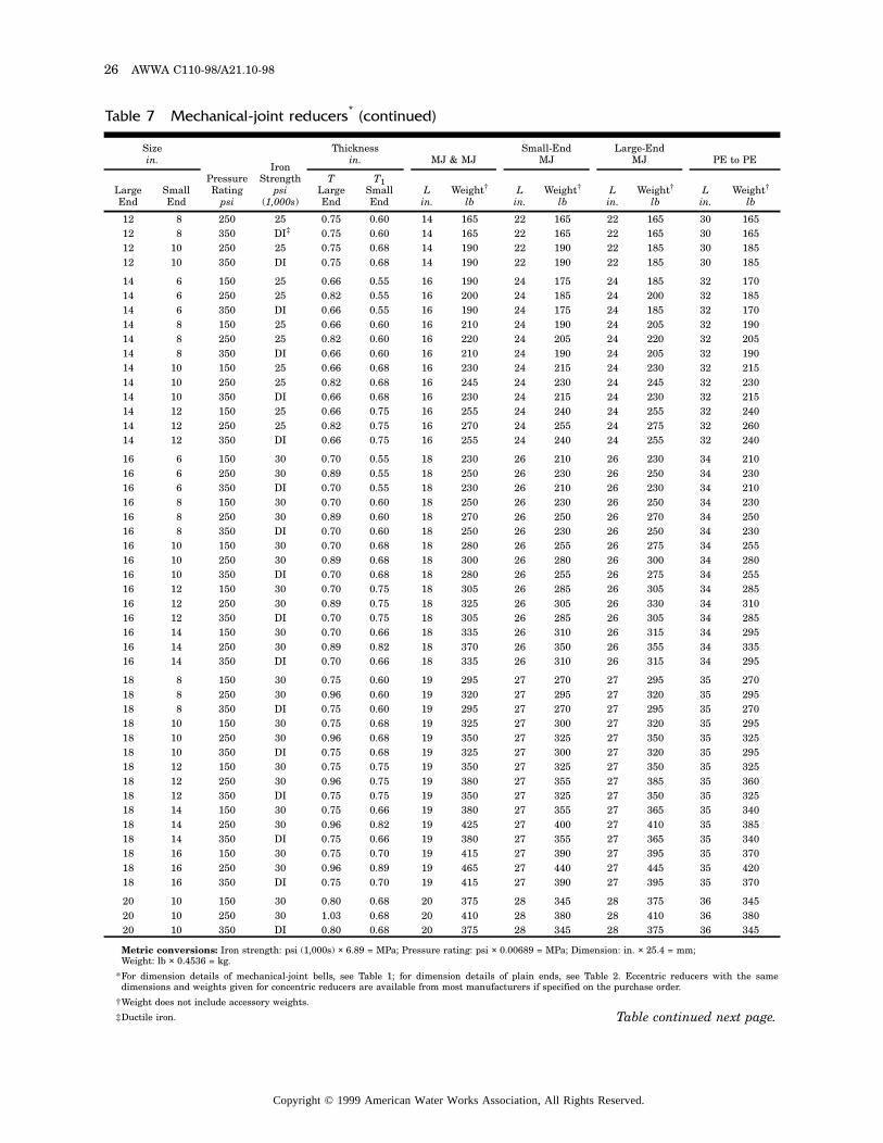
26 AWWA C110-98/A21.10-98
Metric conversions: Iron strength: psi (1,000s) × 6.89 = MPa; Pressure rating: psi × 0.00689 = MPa; Dimension: in. × 25.4 = mm; Weight: lb × 0.4536 = kg.
*For dimension details of mechanical-joint bells, see Table 1; for dimension details of plain ends, see Table 2. Eccentric reducers with the samedimensions and weights given for concentric reducers are available from most manufacturers if specified on the purchase order.
†Weight does not include accessory weights.
‡Ductile iron.
Table 7 Mechanical-joint reducers* (continued)
Sizein.
Pressure Rating
psi
Iron Strength
psi (1,000s)
Thicknessin. MJ & MJ
Small-EndMJ
Large-EndMJ PE to PE
Large End
Small End
TLarge End
T1Small End
Lin.
Weight†
lbL
in.Weight†
lbLin.
Weight†
lbLin.
Weight†
lb
12 8 250 25 0.75 0.60 14 165 22 165 22 165 30 16512 8 350 DI‡ 0.75 0.60 14 165 22 165 22 165 30 16512 10 250 25 0.75 0.68 14 190 22 190 22 185 30 18512 10 350 DI 0.75 0.68 14 190 22 190 22 185 30 185
14 6 150 25 0.66 0.55 16 190 24 175 24 185 32 17014 6 250 25 0.82 0.55 16 200 24 185 24 200 32 18514 6 350 DI 0.66 0.55 16 190 24 175 24 185 32 17014 8 150 25 0.66 0.60 16 210 24 190 24 205 32 19014 8 250 25 0.82 0.60 16 220 24 205 24 220 32 20514 8 350 DI 0.66 0.60 16 210 24 190 24 205 32 19014 10 150 25 0.66 0.68 16 230 24 215 24 230 32 21514 10 250 25 0.82 0.68 16 245 24 230 24 245 32 23014 10 350 DI 0.66 0.68 16 230 24 215 24 230 32 21514 12 150 25 0.66 0.75 16 255 24 240 24 255 32 24014 12 250 25 0.82 0.75 16 270 24 255 24 275 32 26014 12 350 DI 0.66 0.75 16 255 24 240 24 255 32 240
16 6 150 30 0.70 0.55 18 230 26 210 26 230 34 21016 6 250 30 0.89 0.55 18 250 26 230 26 250 34 23016 6 350 DI 0.70 0.55 18 230 26 210 26 230 34 21016 8 150 30 0.70 0.60 18 250 26 230 26 250 34 23016 8 250 30 0.89 0.60 18 270 26 250 26 270 34 25016 8 350 DI 0.70 0.60 18 250 26 230 26 250 34 23016 10 150 30 0.70 0.68 18 280 26 255 26 275 34 25516 10 250 30 0.89 0.68 18 300 26 280 26 300 34 28016 10 350 DI 0.70 0.68 18 280 26 255 26 275 34 25516 12 150 30 0.70 0.75 18 305 26 285 26 305 34 28516 12 250 30 0.89 0.75 18 325 26 305 26 330 34 31016 12 350 DI 0.70 0.75 18 305 26 285 26 305 34 28516 14 150 30 0.70 0.66 18 335 26 310 26 315 34 29516 14 250 30 0.89 0.82 18 370 26 350 26 355 34 33516 14 350 DI 0.70 0.66 18 335 26 310 26 315 34 295
18 8 150 30 0.75 0.60 19 295 27 270 27 295 35 27018 8 250 30 0.96 0.60 19 320 27 295 27 320 35 29518 8 350 DI 0.75 0.60 19 295 27 270 27 295 35 27018 10 150 30 0.75 0.68 19 325 27 300 27 320 35 29518 10 250 30 0.96 0.68 19 350 27 325 27 350 35 32518 10 350 DI 0.75 0.68 19 325 27 300 27 320 35 29518 12 150 30 0.75 0.75 19 350 27 325 27 350 35 32518 12 250 30 0.96 0.75 19 380 27 355 27 385 35 36018 12 350 DI 0.75 0.75 19 350 27 325 27 350 35 32518 14 150 30 0.75 0.66 19 380 27 355 27 365 35 34018 14 250 30 0.96 0.82 19 425 27 400 27 410 35 38518 14 350 DI 0.75 0.66 19 380 27 355 27 365 35 34018 16 150 30 0.75 0.70 19 415 27 390 27 395 35 37018 16 250 30 0.96 0.89 19 465 27 440 27 445 35 42018 16 350 DI 0.75 0.70 19 415 27 390 27 395 35 370
20 10 150 30 0.80 0.68 20 375 28 345 28 375 36 34520 10 250 30 1.03 0.68 20 410 28 380 28 410 36 38020 10 350 DI 0.80 0.68 20 375 28 345 28 375 36 345
Table continued next page.
Copyright © 1999 American Water Works Association, All Rights Reserved.
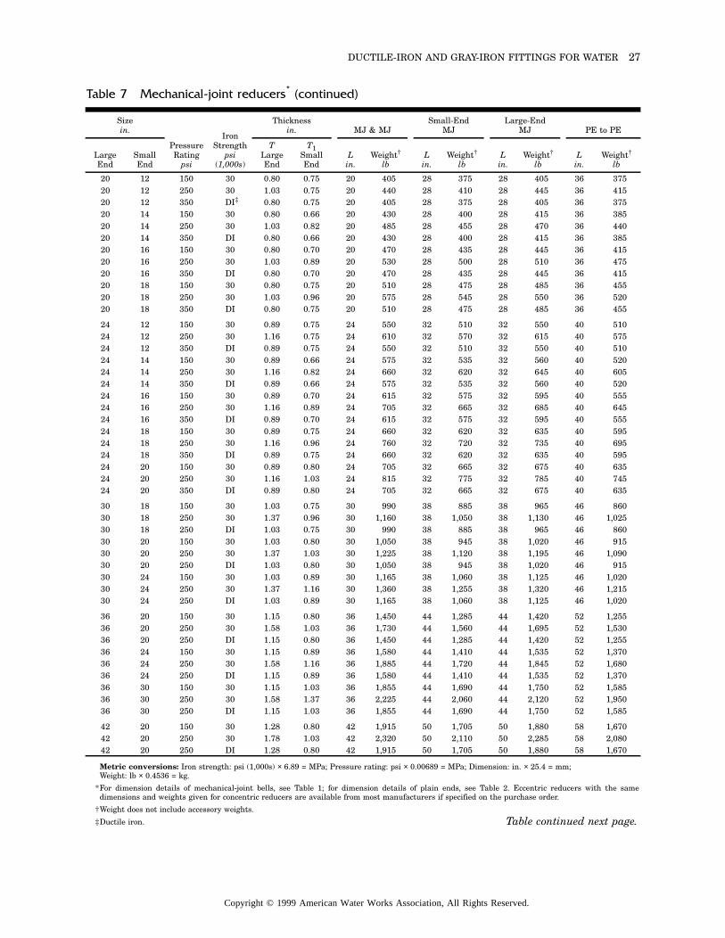
DUCTILE-IRON AND GRAY-IRON FITTINGS FOR WATER 27
Metric conversions: Iron strength: psi (1,000s) × 6.89 = MPa; Pressure rating: psi × 0.00689 = MPa; Dimension: in. × 25.4 = mm; Weight: lb × 0.4536 = kg.
*For dimension details of mechanical-joint bells, see Table 1; for dimension details of plain ends, see Table 2. Eccentric reducers with the samedimensions and weights given for concentric reducers are available from most manufacturers if specified on the purchase order.
†Weight does not include accessory weights.
‡Ductile iron.
Table 7 Mechanical-joint reducers* (continued)
Sizein.
Pressure Rating
psi
Iron Strength
psi (1,000s)
Thicknessin. MJ & MJ
Small-EndMJ
Large-EndMJ PE to PE
Large End
Small End
TLarge End
T1Small End
Lin.
Weight†
lbL
in.Weight†
lbLin.
Weight†
lbLin.
Weight†
lb
20 12 150 30 0.80 0.75 20 405 28 375 28 405 36 37520 12 250 30 1.03 0.75 20 440 28 410 28 445 36 41520 12 350 DI‡ 0.80 0.75 20 405 28 375 28 405 36 37520 14 150 30 0.80 0.66 20 430 28 400 28 415 36 38520 14 250 30 1.03 0.82 20 485 28 455 28 470 36 44020 14 350 DI 0.80 0.66 20 430 28 400 28 415 36 38520 16 150 30 0.80 0.70 20 470 28 435 28 445 36 41520 16 250 30 1.03 0.89 20 530 28 500 28 510 36 47520 16 350 DI 0.80 0.70 20 470 28 435 28 445 36 41520 18 150 30 0.80 0.75 20 510 28 475 28 485 36 45520 18 250 30 1.03 0.96 20 575 28 545 28 550 36 52020 18 350 DI 0.80 0.75 20 510 28 475 28 485 36 455
24 12 150 30 0.89 0.75 24 550 32 510 32 550 40 51024 12 250 30 1.16 0.75 24 610 32 570 32 615 40 57524 12 350 DI 0.89 0.75 24 550 32 510 32 550 40 51024 14 150 30 0.89 0.66 24 575 32 535 32 560 40 52024 14 250 30 1.16 0.82 24 660 32 620 32 645 40 60524 14 350 DI 0.89 0.66 24 575 32 535 32 560 40 52024 16 150 30 0.89 0.70 24 615 32 575 32 595 40 55524 16 250 30 1.16 0.89 24 705 32 665 32 685 40 64524 16 350 DI 0.89 0.70 24 615 32 575 32 595 40 55524 18 150 30 0.89 0.75 24 660 32 620 32 635 40 59524 18 250 30 1.16 0.96 24 760 32 720 32 735 40 69524 18 350 DI 0.89 0.75 24 660 32 620 32 635 40 59524 20 150 30 0.89 0.80 24 705 32 665 32 675 40 63524 20 250 30 1.16 1.03 24 815 32 775 32 785 40 74524 20 350 DI 0.89 0.80 24 705 32 665 32 675 40 635
30 18 150 30 1.03 0.75 30 990 38 885 38 965 46 86030 18 250 30 1.37 0.96 30 1,160 38 1,050 38 1,130 46 1,02530 18 250 DI 1.03 0.75 30 990 38 885 38 965 46 86030 20 150 30 1.03 0.80 30 1,050 38 945 38 1,020 46 91530 20 250 30 1.37 1.03 30 1,225 38 1,120 38 1,195 46 1,09030 20 250 DI 1.03 0.80 30 1,050 38 945 38 1,020 46 91530 24 150 30 1.03 0.89 30 1,165 38 1,060 38 1,125 46 1,02030 24 250 30 1.37 1.16 30 1,360 38 1,255 38 1,320 46 1,21530 24 250 DI 1.03 0.89 30 1,165 38 1,060 38 1,125 46 1,020
36 20 150 30 1.15 0.80 36 1,450 44 1,285 44 1,420 52 1,25536 20 250 30 1.58 1.03 36 1,730 44 1,560 44 1,695 52 1,53036 20 250 DI 1.15 0.80 36 1,450 44 1,285 44 1,420 52 1,25536 24 150 30 1.15 0.89 36 1,580 44 1,410 44 1,535 52 1,37036 24 250 30 1.58 1.16 36 1,885 44 1,720 44 1,845 52 1,68036 24 250 DI 1.15 0.89 36 1,580 44 1,410 44 1,535 52 1,37036 30 150 30 1.15 1.03 36 1,855 44 1,690 44 1,750 52 1,58536 30 250 30 1.58 1.37 36 2,225 44 2,060 44 2,120 52 1,95036 30 250 DI 1.15 1.03 36 1,855 44 1,690 44 1,750 52 1,585
42 20 150 30 1.28 0.80 42 1,915 50 1,705 50 1,880 58 1,67042 20 250 30 1.78 1.03 42 2,320 50 2,110 50 2,285 58 2,08042 20 250 DI 1.28 0.80 42 1,915 50 1,705 50 1,880 58 1,670
Table continued next page.
Copyright © 1999 American Water Works Association, All Rights Reserved.
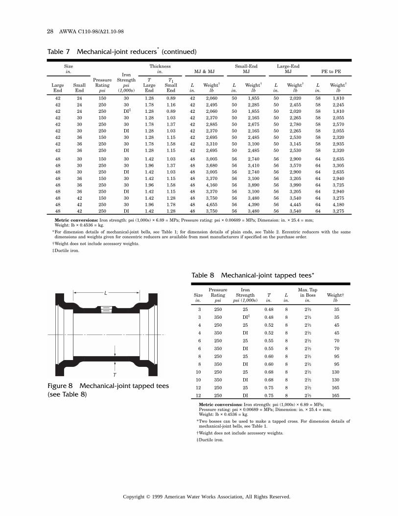
28 AWWA C110-98/A21.10-98
Metric conversions: Iron strength: psi (1,000s) × 6.89 = MPa; Pressure rating: psi × 0.00689 = MPa; Dimension: in. × 25.4 = mm; Weight: lb × 0.4536 = kg.
*For dimension details of mechanical-joint bells, see Table 1; for dimension details of plain ends, see Table 2. Eccentric reducers with the samedimensions and weights given for concentric reducers are available from most manufacturers if specified on the purchase order.
†Weight does not include accessory weights.
‡Ductile iron.
Table 7 Mechanical-joint reducers* (continued)
Sizein.
Pressure Rating
psi
Iron Strength
psi (1,000s)
Thicknessin. MJ & MJ
Small-EndMJ
Large-EndMJ PE to PE
Large End
Small End
TLarge End
T1Small End
Lin.
Weight†
lbL
in.Weight†
lbLin.
Weight†
lbLin.
Weight†
lb
42 24 150 30 1.28 0.89 42 2,060 50 1,855 50 2,020 58 1,81042 24 250 30 1.78 1.16 42 2,495 50 2,285 50 2,455 58 2,24542 24 250 DI‡ 1.28 0.89 42 2,060 50 1,855 50 2,020 58 1,81042 30 150 30 1.28 1.03 42 2,370 50 2,165 50 2,265 58 2,05542 30 250 30 1.78 1.37 42 2,885 50 2,675 50 2,780 58 2,57042 30 250 DI 1.28 1.03 42 2,370 50 2,165 50 2,265 58 2,05542 36 150 30 1.28 1.15 42 2,695 50 2,485 50 2,530 58 2,32042 36 250 30 1.78 1.58 42 3,310 50 3,100 50 3,145 58 2,93542 36 250 DI 1.28 1.15 42 2,695 50 2,485 50 2,530 58 2,320
48 30 150 30 1.42 1.03 48 3,005 56 2,740 56 2,900 64 2,63548 30 250 30 1.96 1.37 48 3,680 56 3,410 56 3,570 64 3,30548 30 250 DI 1.42 1.03 48 3,005 56 2,740 56 2,900 64 2,63548 36 150 30 1.42 1.15 48 3,370 56 3,100 56 3,205 64 2,94048 36 250 30 1.96 1.58 48 4,160 56 3,890 56 3,990 64 3,72548 36 250 DI 1.42 1.15 48 3,370 56 3,100 56 3,205 64 2,94048 42 150 30 1.42 1.28 48 3,750 56 3,480 56 3,540 64 3,27548 42 250 30 1.96 1.78 48 4,655 56 4,390 56 4,445 64 4,18048 42 250 DI 1.42 1.28 48 3,750 56 3,480 56 3,540 64 3,275
Metric conversions: Iron strength: psi (1,000s) × 6.89 = MPa; Pressure rating: psi × 0.00689 = MPa; Dimension: in. × 25.4 = mm; Weight: lb × 0.4536 = kg.
*Two bosses can be used to make a tapped cross. For dimension details ofmechanical-joint bells, see Table 1.
†Weight does not include accessory weights.
‡Ductile iron.
Table 8 Mechanical-joint tapped tees*
Sizein.
Pressure Rating
psi
Iron Strength
psi (1,000s)Tin.
Lin.
Max. Tap in Boss
in.Weight†
lb
3 250 25 0.48 8 21⁄2 35
3 350 DI‡ 0.48 8 21⁄2 35
4 250 25 0.52 8 21⁄2 45
4 350 DI 0.52 8 21⁄2 45
6 250 25 0.55 8 21⁄2 70
6 350 DI 0.55 8 21⁄2 70
8 250 25 0.60 8 21⁄2 95
8 350 DI 0.60 8 21⁄2 95
10 250 25 0.68 8 21⁄2 130
10 350 DI 0.68 8 21⁄2 130
12 250 25 0.75 8 21⁄2 165
12 250 DI 0.75 8 21⁄2 165
L
T
Figure 8 Mechanical-joint tapped tees (see Table 8)
Copyright © 1999 American Water Works Association, All Rights Reserved.
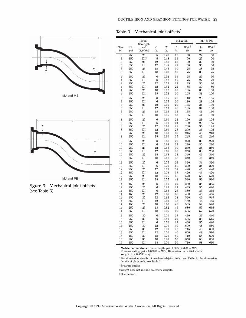
DUCTILE-IRON AND GRAY-IRON FITTINGS FOR WATER 29
MJ and MJ
T
L
D
MJ and PE
T
L
D
Metric conversions: Iron strength: psi (1,000s) × 6.89 = MPa; Pressure rating: psi × 0.00689 = MPa; Dimension: in. × 25.4 = mm; Weight: lb × 0.4536 = kg.
*For dimension details of mechanical-joint bells, see Table 1; for dimensiondetails of plain ends, see Table 2.
†Pressure rating.
‡Weight does not include accessory weights.
§Ductile iron.
Table 9 Mechanical-joint offsets*
Sizein.
PR†
psi
Iron Strength
psi(1,000s)
Din.
Tin.
MJ & MJ MJ & PE
Lin.
Wgt.‡
lbLin.
Wgt.‡
lb
3 250 25 5 0.48 19 50 27 503 350 DI§ 5 0.48 19 50 27 503 250 25 12 0.48 22 60 30 603 350 DI 12 0.48 22 60 30 603 250 25 18 0.48 30 75 38 753 350 DI 18 0.48 30 75 38 75
4 250 25 6 0.52 19 75 27 704 350 DI 6 0.52 19 75 27 704 250 25 12 0.52 22 85 30 804 350 DI 12 0.52 22 85 30 804 250 25 18 0.52 30 105 38 1004 350 DI 18 0.52 30 105 38 100
6 250 25 6 0.55 20 110 28 1056 350 DI 6 0.55 20 110 28 1056 250 25 12 0.55 26 135 34 1306 350 DI 12 0.55 26 135 34 1306 250 25 18 0.55 33 165 41 1606 350 DI 18 0.55 33 165 41 160
8 250 25 6 0.60 21 150 29 1558 350 DI 6 0.60 21 160 29 1558 250 25 12 0.60 28 200 36 1958 350 DI 12 0.60 28 200 36 1958 250 25 18 0.60 35 245 43 2408 350 DI 18 0.60 35 245 43 240
10 250 25 6 0.68 22 220 30 22010 350 DI 6 0.68 22 220 30 22010 250 25 12 0.68 30 250 38 28010 350 DI 12 0.68 30 250 38 28010 250 25 18 0.68 38 340 46 34010 350 DI 18 0.68 38 340 46 340
12 250 25 6 0.75 26 320 34 32012 350 DI 6 0.75 26 320 34 32012 250 25 12 0.75 37 420 45 42012 350 DI 12 0.75 37 420 45 42012 250 25 18 0.75 48 520 56 52012 350 DI 18 0.75 48 520 56 520
14 150 25 6 0.66 27 380 35 36514 250 25 6 0.82 27 435 35 42014 350 DI 6 0.66 27 380 35 36514 150 25 12 0.66 38 480 46 46514 250 25 12 0.82 38 560 46 54514 350 DI 12 0.66 38 480 46 46514 150 25 18 0.66 49 585 57 57014 250 25 18 0.82 49 680 57 66514 350 DI 18 0.66 49 585 57 570
16 150 30 6 0.70 27 460 35 44016 250 30 6 0.89 27 535 35 51516 350 DI 6 0.70 27 460 35 44016 150 30 12 0.70 40 600 48 58016 250 30 12 0.89 40 715 48 69016 350 DI 12 0.70 40 600 48 58016 150 30 18 0.70 50 710 58 69016 250 30 18 0.89 50 850 58 83016 350 DI 18 0.70 50 710 58 690
Figure 9 Mechanical-joint offsets (see Table 9)
Copyright © 1999 American Water Works Association, All Rights Reserved.
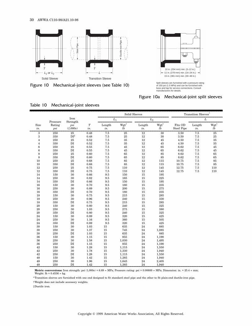
30 AWWA C110-98/A21.10-98
L1 or L2
Solid Sleeve
TL
Transition Sleeve
T
Duc
tile-
Iron
Pip
e
Ste
el P
ipe
10 in. (254 mm) min. (3–12 in.)
11 in. (279 mm) min. (14–24 in.)
15 in. (381 mm) min. (30–48 in.)
Split sleeves are furnished with a pressure rating of 150 psi (1.0 MPa) and can be furnished with boss and tap for service connections. Consult manufacturers for details.
Figure 10 Mechanical-joint sleeves (see Table 10)
Figure 10a Mechanical-joint split sleeves
Metric conversions: Iron strength: psi (1,000s) × 6.89 = MPa; Pressure rating: psi × 0.00689 = MPa; Dimension: in. × 25.4 = mm; Weight: lb × 0.4536 = kg.
*Transition sleeves are furnished with one end designed to fit standard steel pipe and the other to fit plain-end ductile-iron pipe.
†Weight does not include accessory weights.
‡Ductile iron.
Table 10 Mechanical-joint sleeves
Sizein.
Pressure Rating
psi
Iron Strength
psi(1,000s)
Tin.
Solid Sleeves Transition Sleeves*
L1 L2
Fits OD Steel Pipe
L
Lengthin.
Wgt†
lbLength
in.Wgt†
lbLength
in.Wgt†
lb
3 250 25 0.48 7.5 25 12 30 3.50 7.5 253 350 DI‡ 0.48 7.5 25 12 30 3.50 7.5 254 250 25 0.52 7.5 35 12 45 4.50 7.5 354 350 DI 0.52 7.5 35 12 45 4.50 7.5 356 250 25 0.55 7.5 45 12 65 6.62 7.5 456 350 DI 0.55 7.5 45 12 65 6.62 7.5 458 250 25 0.60 7.5 65 12 85 8.62 7.5 658 350 DI 0.60 7.5 65 12 85 8.62 7.5 65
10 250 25 0.68 7.5 85 12 115 10.75 7.5 8510 350 DI 0.68 7.5 85 12 115 10.75 7.5 8512 250 25 0.75 7.5 110 12 145 12.75 7.5 11012 350 DI 0.75 7.5 110 12 145 12.75 7.5 11014 150 30 0.66 9.5 150 15 19514 250 30 0.82 9.5 165 15 22514 350 DI 0.66 9.5 150 15 19516 150 30 0.70 9.5 180 15 23516 250 30 0.89 9.5 200 15 27516 350 DI 0.70 9.5 180 15 23518 150 30 0.75 9.5 215 15 28518 250 30 0.96 9.5 240 15 33018 350 DI 0.75 9.5 215 15 28520 150 30 0.80 9.5 240 15 32520 250 30 1.03 9.5 275 15 38020 350 DI 0.80 9.5 240 15 32524 150 30 0.89 9.5 320 15 42524 250 30 1.16 9.5 360 15 50524 350 DI 0.89 9.5 320 15 42530 150 30 1.03 15 635 24 88530 250 30 1.37 15 745 24 1,08530 250 DI 1.03 15 635 24 88536 150 30 1.15 15 855 24 1,19036 250 30 1.58 15 1,030 24 1,49536 250 DI 1.15 15 855 24 1,19042 150 30 1.28 15 1,115 24 1,55042 250 30 1.78 15 1,330 24 1,94042 250 DI 1.28 15 1,115 24 1,55048 150 30 1.42 15 1,385 24 1,94048 250 30 1.96 15 1,645 24 2,40548 250 DI 1.42 15 1,385 24 1,940
Copyright © 1999 American Water Works Association, All Rights Reserved.
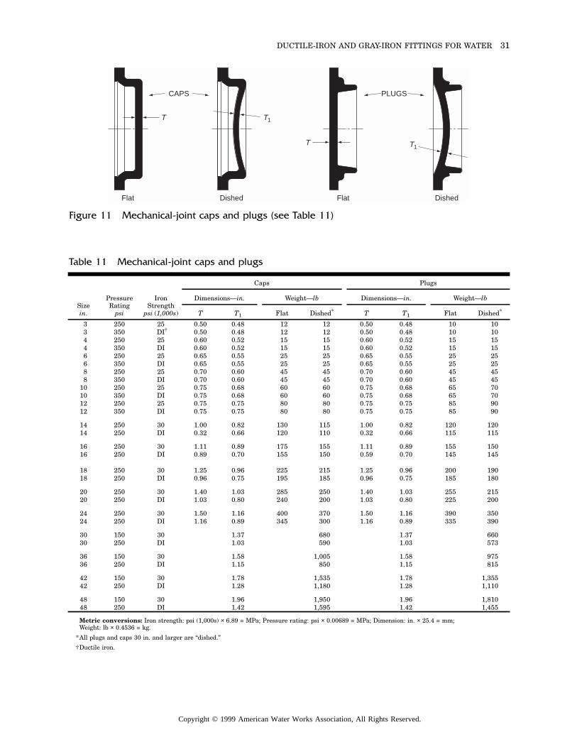
DUCTILE-IRON AND GRAY-IRON FITTINGS FOR WATER 31
T
Flat
CAPS
T1
Dished
T
Flat
PLUGS
T1
Dished
Figure 11 Mechanical-joint caps and plugs (see Table 11)
Metric conversions: Iron strength: psi (1,000s) × 6.89 = MPa; Pressure rating: psi × 0.00689 = MPa; Dimension: in. × 25.4 = mm; Weight: lb × 0.4536 = kg.
*All plugs and caps 30 in. and larger are “dished.”
†Ductile iron.
Table 11 Mechanical-joint caps and plugs
Sizein.
Pressure Rating
psi
Iron Strength
psi (1,000s)
Caps Plugs
Dimensions—in. Weight—lb Dimensions—in. Weight—lb
T T1 Flat Dished* T T1 Flat Dished*
3 250 25 0.50 0.48 12 12 0.50 0.48 10 103 350 DI† 0.50 0.48 12 12 0.50 0.48 10 104 250 25 0.60 0.52 15 15 0.60 0.52 15 154 350 DI 0.60 0.52 15 15 0.60 0.52 15 156 250 25 0.65 0.55 25 25 0.65 0.55 25 256 350 DI 0.65 0.55 25 25 0.65 0.55 25 258 250 25 0.70 0.60 45 45 0.70 0.60 45 458 350 DI 0.70 0.60 45 45 0.70 0.60 45 45
10 250 25 0.75 0.68 60 60 0.75 0.68 65 7010 350 DI 0.75 0.68 60 60 0.75 0.68 65 7012 250 25 0.75 0.75 80 80 0.75 0.75 85 9012 350 DI 0.75 0.75 80 80 0.75 0.75 85 90
14 250 30 1.00 0.82 130 115 1.00 0.82 120 12014 250 DI 0.32 0.66 120 110 0.32 0.66 115 115
16 250 30 1.11 0.89 175 155 1.11 0.89 155 15016 250 DI 0.89 0.70 155 150 0.59 0.70 145 145
18 250 30 1.25 0.96 225 215 1.25 0.96 200 19018 250 DI 0.96 0.75 195 185 0.96 0.75 185 180
20 250 30 1.40 1.03 285 250 1.40 1.03 255 21520 250 DI 1.03 0.80 240 200 1.03 0.80 225 200
24 250 30 1.50 1.16 400 370 1.50 1.16 390 35024 250 DI 1.16 0.89 345 300 1.16 0.89 335 390
30 150 30 1.37 680 1.37 66030 250 DI 1.03 590 1.03 573
36 150 30 1.58 1,005 1.58 97536 250 DI 1.15 850 1.15 815
42 150 30 1.78 1,535 1.78 1,35542 250 DI 1.28 1,180 1.28 1,110
48 150 30 1.96 1,950 1.96 1,81048 250 DI 1.42 1,595 1.42 1,455
Copyright © 1999 American Water Works Association, All Rights Reserved.
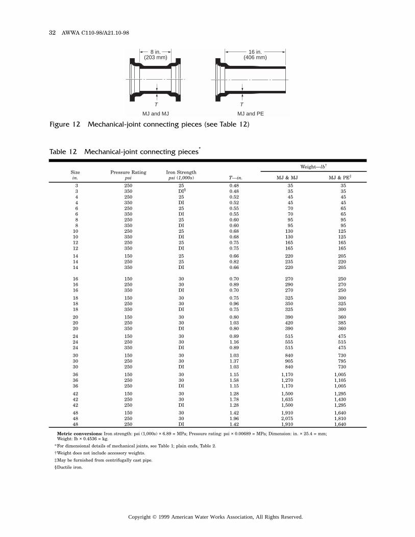
32 AWWA C110-98/A21.10-98
8 in.(203 mm)
MJ and MJ
T
16 in.(406 mm)
MJ and PE
T
Figure 12 Mechanical-joint connecting pieces (see Table 12)
Metric conversions: Iron strength: psi (1,000s) × 6.89 = MPa; Pressure rating: psi × 0.00689 = MPa; Dimension: in. × 25.4 = mm; Weight: lb × 0.4536 = kg.
*For dimensional details of mechanical joints, see Table 1; plain ends, Table 2.
†Weight does not include accessory weights.
‡May be furnished from centrifugally cast pipe.
§Ductile iron.
Table 12 Mechanical-joint connecting pieces*
Sizein.
Pressure Ratingpsi
Iron Strengthpsi (1,000s) T—in.
Weight—lb†
MJ & MJ MJ & PE‡
3 250 25 0.48 35 353 350 DI§ 0.48 35 354 250 25 0.52 45 454 350 DI 0.52 45 456 250 25 0.55 70 656 350 DI 0.55 70 658 250 25 0.60 95 958 350 DI 0.60 95 95
10 250 25 0.68 130 12510 350 DI 0.68 130 12512 250 25 0.75 165 16512 350 DI 0.75 165 165
14 150 25 0.66 220 20514 250 25 0.82 235 22014 350 DI 0.66 220 205
16 150 30 0.70 270 25016 250 30 0.89 290 27016 350 DI 0.70 270 250
18 150 30 0.75 325 30018 250 30 0.96 350 32518 350 DI 0.75 325 300
20 150 30 0.80 390 36020 250 30 1.03 420 38520 350 DI 0.80 390 360
24 150 30 0.89 515 47524 250 30 1.16 555 51524 350 DI 0.89 515 475
30 150 30 1.03 840 73030 250 30 1.37 905 79530 250 DI 1.03 840 730
36 150 30 1.15 1,170 1,00536 250 30 1.58 1,270 1,10536 250 DI 1.15 1,170 1,005
42 150 30 1.28 1,500 1,29542 250 30 1.78 1,635 1,43042 250 DI 1.28 1,500 1,295
48 150 30 1.42 1,910 1,64048 250 30 1.96 2,075 1,81048 250 DI 1.42 1,910 1,640
Copyright © 1999 American Water Works Association, All Rights Reserved.
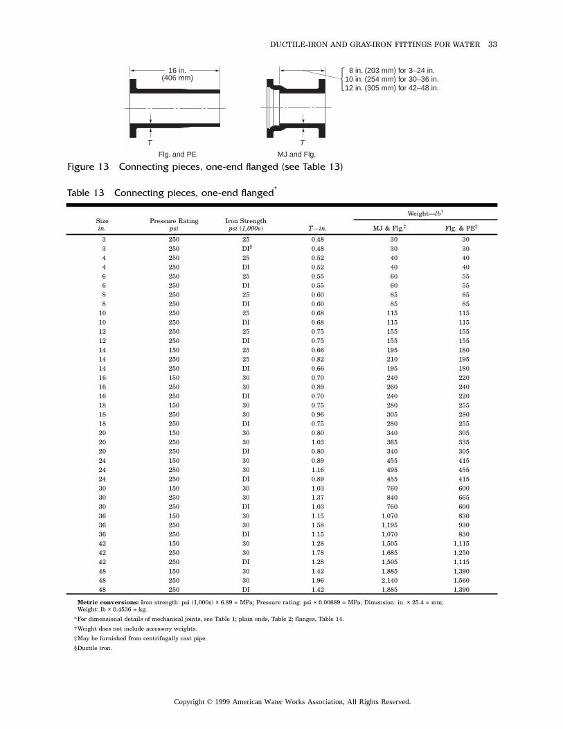
DUCTILE-IRON AND GRAY-IRON FITTINGS FOR WATER 33
8 in. (203 mm) for 3–24 in.10 in. (254 mm) for 30–36 in.12 in. (305 mm) for 42–48 in.
MJ and Flg.
T
16 in.(406 mm)
Flg. and PE
T
Figure 13 Connecting pieces, one-end flanged (see Table 13)
Metric conversions: Iron strength: psi (1,000s) × 6.89 = MPa; Pressure rating: psi × 0.00689 = MPa; Dimension: in. × 25.4 = mm; Weight: lb × 0.4536 = kg.
*For dimensional details of mechanical joints, see Table 1; plain ends, Table 2; flanges, Table 14.
†Weight does not include accessory weights.
‡May be furnished from centrifugally cast pipe.
§Ductile iron.
Table 13 Connecting pieces, one-end flanged*
Sizein.
Pressure Ratingpsi
Iron Strengthpsi (1,000s) T—in.
Weight—lb†
MJ & Flg.‡ Flg. & PE‡
3 250 25 0.48 30 303 250 DI§ 0.48 30 304 250 25 0.52 40 404 250 DI 0.52 40 406 250 25 0.55 60 556 250 DI 0.55 60 558 250 25 0.60 85 858 250 DI 0.60 85 85
10 250 25 0.68 115 11510 250 DI 0.68 115 11512 250 25 0.75 155 15512 250 DI 0.75 155 15514 150 25 0.66 195 18014 250 25 0.82 210 19514 250 DI 0.66 195 18016 150 30 0.70 240 22016 250 30 0.89 260 24016 250 DI 0.70 240 22018 150 30 0.75 280 25518 250 30 0.96 305 28018 250 DI 0.75 280 25520 150 30 0.80 340 30520 250 30 1.03 365 33520 250 DI 0.80 340 30524 150 30 0.89 455 41524 250 30 1.16 495 45524 250 DI 0.89 455 41530 150 30 1.03 760 60030 250 30 1.37 840 66530 250 DI 1.03 760 60036 150 30 1.15 1,070 83036 250 30 1.58 1,195 93036 250 DI 1.15 1,070 83042 150 30 1.28 1,505 1,11542 250 30 1.78 1,685 1,25042 250 DI 1.28 1,505 1,11548 150 30 1.42 1,885 1,39048 250 30 1.96 2,140 1,56048 250 DI 1.42 1,885 1,390
Copyright © 1999 American Water Works Association, All Rights Reserved.
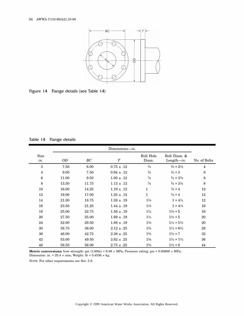
34 AWWA C110-98/A21.10-98
BC
OD
T
Size
Figure 14 Flange details (see Table 14)
Metric conversions: Iron strength: psi (1,000s) × 6.89 = MPa; Pressure rating: psi × 0.00689 = MPa; Dimension: in. × 25.4 = mm; Weight: lb × 0.4536 = kg.
NOTE: For other requirements see Sec. 5.9.
Table 14 Flange details
Sizein.
Dimensions—in.
No. of BoltsOD BC TBolt Hole
Diam.Bolt Diam. & Length—in.
3 7.50 6.00 0.75 ± .12 3⁄4 5⁄8 × 21⁄2 4
4 9.00 7.50 0.94 ± .12 3⁄4 5⁄8 × 3 8
6 11.00 9.50 1.00 ± .12 7⁄8 3⁄4 × 31⁄2 8
8 13.50 11.75 1.12 ± .12 7⁄8 3⁄4 × 31⁄2 8
10 16.00 14.25 1.19 ± .12 1 7⁄8 × 4 12
12 19.00 17.00 1.25 ± .12 1 7⁄8 × 4 12
14 21.00 18.75 1.38 ± .19 11⁄8 1 × 41⁄4 12
16 23.50 21.25 1.44 ± .19 11⁄8 1 × 41⁄4 16
18 25.00 22.75 1.56 ± .19 11⁄4 11⁄8 × 5 16
20 27.50 25.00 1.69 ± .19 11⁄4 11⁄8 × 5 20
24 32.00 29.50 1.88 ± .19 13⁄8 11⁄4 × 51⁄2 20
30 38.75 36.00 2.12 ± .25 13⁄8 11⁄4 × 61⁄2 28
36 46.00 42.75 2.38 ± .25 15⁄8 11⁄2 × 7 32
42 53.00 49.50 2.62 ± .25 15⁄8 11⁄2 × 71⁄2 36
48 59.50 56.00 2.75 ± .25 15⁄8 11⁄2 × 8 44
Copyright © 1999 American Water Works Association, All Rights Reserved.
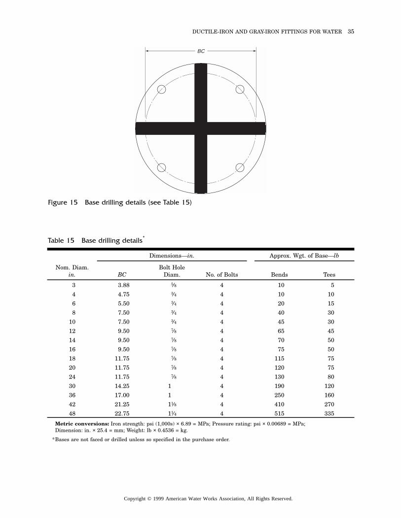
DUCTILE-IRON AND GRAY-IRON FITTINGS FOR WATER 35
BC
Figure 15 Base drilling details (see Table 15)
Metric conversions: Iron strength: psi (1,000s) × 6.89 = MPa; Pressure rating: psi × 0.00689 = MPa; Dimension: in. × 25.4 = mm; Weight: lb × 0.4536 = kg.
*Bases are not faced or drilled unless so specified in the purchase order.
Table 15 Base drilling details*
Nom. Diam.in.
Dimensions—in. Approx. Wgt. of Base—lb
BCBolt Hole
Diam. No. of Bolts Bends Tees
3 3.88 5⁄8 4 10 5
4 4.75 3⁄4 4 10 10
6 5.50 3⁄4 4 20 15
8 7.50 3⁄4 4 40 30
10 7.50 3⁄4 4 45 30
12 9.50 7⁄8 4 65 45
14 9.50 7⁄8 4 70 50
16 9.50 7⁄8 4 75 50
18 11.75 7⁄8 4 115 75
20 11.75 7⁄8 4 120 75
24 11.75 7⁄8 4 130 80
30 14.25 1 4 190 120
36 17.00 1 4 250 160
42 21.25 11⁄8 4 410 270
48 22.75 11⁄4 4 515 335
Copyright © 1999 American Water Works Association, All Rights Reserved.
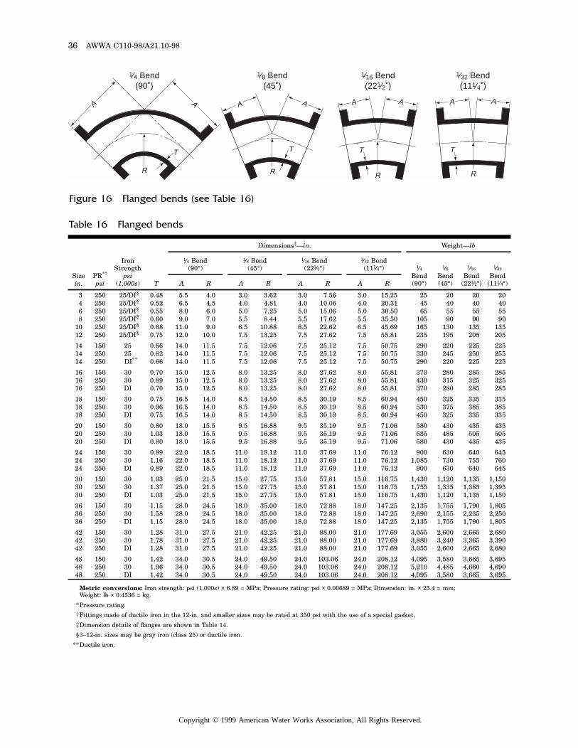
36 AWWA C110-98/A21.10-98
AA
R
T
A A
1⁄4 Bend(90˚)
1⁄16 Bend(221⁄2˚)
R
T
A
1⁄32 Bend(111⁄4˚)
R
T
A
1⁄8 Bend(45˚)
R
T
A A
Figure 16 Flanged bends (see Table 16)
Metric conversions: Iron strength: psi (1,000s) × 6.89 = MPa; Pressure rating: psi × 0.00689 = MPa; Dimension: in. × 25.4 = mm; Weight: lb × 0.4536 = kg.
*Pressure rating.
†Fittings made of ductile iron in the 12-in. and smaller sizes may be rated at 350 psi with the use of a special gasket.
‡Dimension details of flanges are shown in Table 14.
§3–12-in. sizes may be gray iron (class 25) or ductile iron.
**Ductile iron.
Table 16 Flanged bends
Sizein.
PR*†
psi
Iron Strength
psi(1,000s) T
Dimensions‡—in. Weight—lb
1⁄4 Bend(90°)
1⁄8 Bend(45°)
1⁄16 Bend(221⁄2°)
1⁄32 Bend(111⁄4°) 1⁄4
Bend (90°)
1⁄8Bend (45°)
1⁄16
Bend (221⁄2°)
1⁄32
Bend (111⁄4°)A R A R A R A R
3 250 25/DI§ 0.48 5.5 4.0 3.0 3.62 3.0 7.56 3.0 15.25 25 20 20 204 250 25/DI§ 0.52 6.5 4.5 4.0 4.81 4.0 10.06 4.0 20.31 45 40 40 406 250 25/DI§ 0.55 8.0 6.0 5.0 7.25 5.0 15.06 5.0 30.50 65 55 55 558 250 25/DI§ 0.60 9.0 7.0 5.5 8.44 5.5 17.62 5.5 35.50 105 90 90 90
10 250 25/DI§ 0.68 11.0 9.0 6.5 10.88 6.5 22.62 6.5 45.69 165 130 135 13512 250 25/DI§ 0.75 12.0 10.0 7.5 13.25 7.5 27.62 7.5 55.81 235 195 205 205
14 150 25 0.66 14.0 11.5 7.5 12.06 7.5 25.12 7.5 50.75 290 220 225 22514 250 25 0.82 14.0 11.5 7.5 12.06 7.5 25.12 7.5 50.75 330 245 250 25514 250 DI** 0.66 14.0 11.5 7.5 12.06 7.5 25.12 7.5 50.75 290 220 225 225
16 150 30 0.70 15.0 12.5 8.0 13.25 8.0 27.62 8.0 55.81 370 280 285 28516 250 30 0.89 15.0 12.5 8.0 13.25 8.0 27.62 8.0 55.81 430 315 325 32516 250 DI 0.70 15.0 12.5 8.0 13.25 8.0 27.62 8.0 55.81 370 280 285 285
18 150 30 0.75 16.5 14.0 8.5 14.50 8.5 30.19 8.5 60.94 450 325 335 33518 250 30 0.96 16.5 14.0 8.5 14.50 8.5 30.19 8.5 60.94 530 375 385 38518 250 DI 0.75 16.5 14.0 8.5 14.50 8.5 30.19 8.5 60.94 450 325 335 335
20 150 30 0.80 18.0 15.5 9.5 16.88 9.5 35.19 9.5 71.06 580 430 435 43520 250 30 1.03 18.0 15.5 9.5 16.88 9.5 35.19 9.5 71.06 685 485 505 50520 250 DI 0.80 18.0 15.5 9.5 16.88 9.5 35.19 9.5 71.06 580 430 435 435
24 150 30 0.89 22.0 18.5 11.0 18.12 11.0 37.69 11.0 76.12 900 630 640 64524 250 30 1.16 22.0 18.5 11.0 18.12 11.0 37.69 11.0 76.12 1,085 730 755 76024 250 DI 0.89 22.0 18.5 11.0 18.12 11.0 37.69 11.0 76.12 900 630 640 645
30 150 30 1.03 25.0 21.5 15.0 27.75 15.0 57.81 15.0 116.75 1,430 1,120 1,135 1,15030 250 30 1.37 25.0 21.5 15.0 27.75 15.0 57.81 15.0 116.75 1,755 1,335 1,385 1,39530 250 DI 1.03 25.0 21.5 15.0 27.75 15.0 57.81 15.0 116.75 1,430 1,120 1,135 1,150
36 150 30 1.15 28.0 24.5 18.0 35.00 18.0 72.88 18.0 147.25 2,135 1,755 1,790 1,80536 250 30 1.58 28.0 24.5 18.0 35.00 18.0 72.88 18.0 147.25 2,690 2,155 2,235 2,25036 250 DI 1.15 28.0 24.5 18.0 35.00 18.0 72.88 18.0 147.25 2,135 1,755 1,790 1,805
42 150 30 1.28 31.0 27.5 21.0 42.25 21.0 88.00 21.0 177.69 3,055 2,600 2,665 2,68042 250 30 1.78 31.0 27.5 21.0 42.25 21.0 88.00 21.0 177.69 3,880 3,240 3,365 3,39042 250 DI 1.28 31.0 27.5 21.0 42.25 21.0 88.00 21.0 177.69 3,055 2,600 2,665 2,680
48 150 30 1.42 34.0 30.5 24.0 49.50 24.0 103.06 24.0 208.12 4,095 3,580 3,665 3,69548 250 30 1.96 34.0 30.5 24.0 49.50 24.0 103.06 24.0 208.12 5,210 4,485 4,660 4,69048 250 DI 1.42 34.0 30.5 24.0 49.50 24.0 103.06 24.0 208.12 4,095 3,580 3,665 3,695
Copyright © 1999 American Water Works Association, All Rights Reserved.
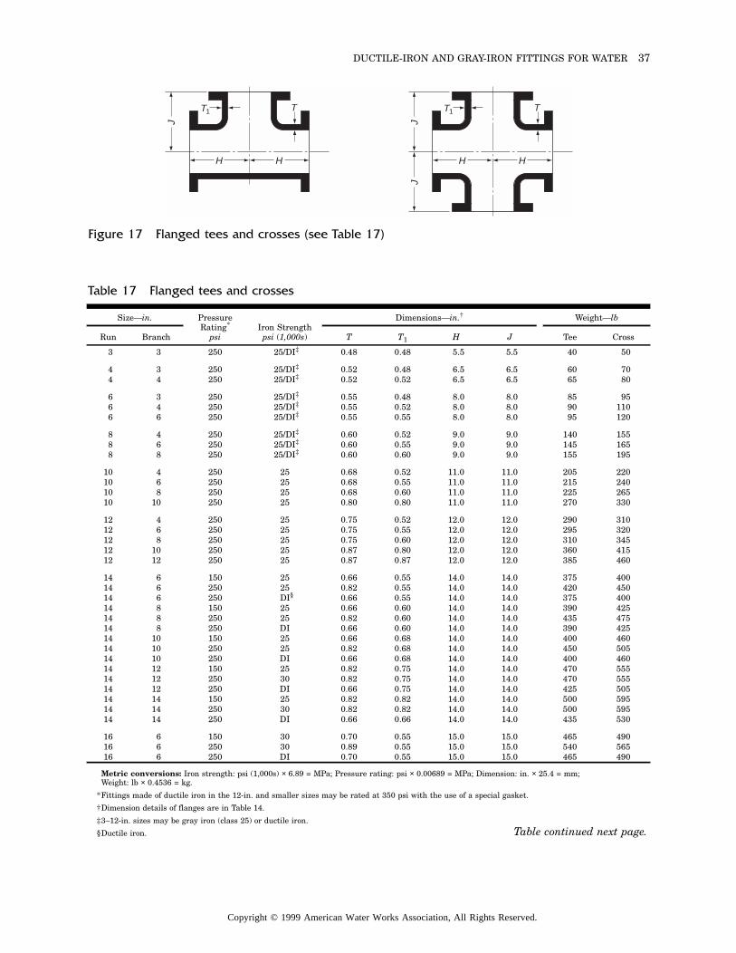
DUCTILE-IRON AND GRAY-IRON FITTINGS FOR WATER 37
TT1
HHJ
TT1
HH
JJ
Figure 17 Flanged tees and crosses (see Table 17)
Metric conversions: Iron strength: psi (1,000s) × 6.89 = MPa; Pressure rating: psi × 0.00689 = MPa; Dimension: in. × 25.4 = mm; Weight: lb × 0.4536 = kg.
*Fittings made of ductile iron in the 12-in. and smaller sizes may be rated at 350 psi with the use of a special gasket.
†Dimension details of flanges are in Table 14.
‡3–12-in. sizes may be gray iron (class 25) or ductile iron.
§Ductile iron.
Table 17 Flanged tees and crosses
Size—in. Pressure Rating*
psiIron Strength
psi (1,000s)
Dimensions—in.† Weight—lb
Run Branch T T1 H J Tee Cross
3 3 250 25/DI‡ 0.48 0.48 5.5 5.5 40 50
4 3 250 25/DI‡ 0.52 0.48 6.5 6.5 60 704 4 250 25/DI‡ 0.52 0.52 6.5 6.5 65 80
6 3 250 25/DI‡ 0.55 0.48 8.0 8.0 85 956 4 250 25/DI‡ 0.55 0.52 8.0 8.0 90 1106 6 250 25/DI‡ 0.55 0.55 8.0 8.0 95 120
8 4 250 25/DI‡ 0.60 0.52 9.0 9.0 140 1558 6 250 25/DI‡ 0.60 0.55 9.0 9.0 145 1658 8 250 25/DI‡ 0.60 0.60 9.0 9.0 155 195
10 4 250 25 0.68 0.52 11.0 11.0 205 22010 6 250 25 0.68 0.55 11.0 11.0 215 24010 8 250 25 0.68 0.60 11.0 11.0 225 26510 10 250 25 0.80 0.80 11.0 11.0 270 330
12 4 250 25 0.75 0.52 12.0 12.0 290 31012 6 250 25 0.75 0.55 12.0 12.0 295 32012 8 250 25 0.75 0.60 12.0 12.0 310 34512 10 250 25 0.87 0.80 12.0 12.0 360 41512 12 250 25 0.87 0.87 12.0 12.0 385 460
14 6 150 25 0.66 0.55 14.0 14.0 375 40014 6 250 25 0.82 0.55 14.0 14.0 420 45014 6 250 DI§ 0.66 0.55 14.0 14.0 375 40014 8 150 25 0.66 0.60 14.0 14.0 390 42514 8 250 25 0.82 0.60 14.0 14.0 435 47514 8 250 DI 0.66 0.60 14.0 14.0 390 42514 10 150 25 0.66 0.68 14.0 14.0 400 46014 10 250 25 0.82 0.68 14.0 14.0 450 50514 10 250 DI 0.66 0.68 14.0 14.0 400 46014 12 150 25 0.82 0.75 14.0 14.0 470 55514 12 250 30 0.82 0.75 14.0 14.0 470 55514 12 250 DI 0.66 0.75 14.0 14.0 425 50514 14 150 25 0.82 0.82 14.0 14.0 500 59514 14 250 30 0.82 0.82 14.0 14.0 500 59514 14 250 DI 0.66 0.66 14.0 14.0 435 530
16 6 150 30 0.70 0.55 15.0 15.0 465 49016 6 250 30 0.89 0.55 15.0 15.0 540 56516 6 250 DI 0.70 0.55 15.0 15.0 465 490
Table continued next page.
Copyright © 1999 American Water Works Association, All Rights Reserved.
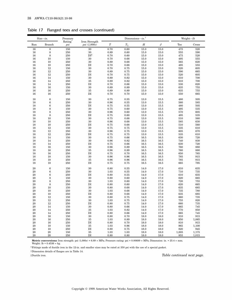
38 AWWA C110-98/A21.10-98
Metric conversions: Iron strength: psi (1,000s) × 6.89 = MPa; Pressure rating: psi × 0.00689 = MPa; Dimension: in. × 25.4 = mm; Weight: lb × 0.4536 = kg.
*Fittings made of ductile iron in the 12-in. and smaller sizes may be rated at 350 psi with the use of a special gasket.
†Dimension details of flanges are in Table 14.
‡Ductile iron.
Table 17 Flanged tees and crosses (continued)
Size—in. Pressure Rating*
psiIron Strength
psi (1,000s)
Dimensions—in.† Weight—lb
Run Branch T T1 H J Tee Cross
16 8 150 30 0.70 0.60 15.0 15.0 475 52016 8 250 30 0.89 0.60 15.0 15.0 555 59016 8 250 DI‡ 0.70 0.60 15.0 15.0 475 52016 10 150 30 0.70 0.68 15.0 15.0 495 55516 10 250 30 0.89 0.68 15.0 15.0 565 62016 10 250 DI 0.70 0.68 15.0 15.0 495 55516 12 150 30 0.70 0.75 15.0 15.0 520 60516 12 250 30 0.89 0.75 15.0 15.0 590 66516 12 250 DI 0.70 0.75 15.0 15.0 520 60516 14 150 30 0.89 0.82 15.0 15.0 610 70016 14 250 35 0.89 0.82 15.0 15.0 610 70016 14 250 DI 0.70 0.66 15.0 15.0 530 62016 16 150 30 0.89 0.89 15.0 15.0 635 75516 16 250 35 0.89 0.89 15.0 15.0 635 75516 16 250 DI 0.70 0.70 15.0 15.0 550 665
18 6 150 30 0.75 0.55 13.0 15.5 480 50518 6 250 30 0.96 0.55 13.0 15.5 560 58518 6 250 DI 0.75 0.55 13.0 15.5 480 50518 8 150 30 0.75 0.60 13.0 15.5 495 53518 8 250 30 0.96 0.60 13.0 15.5 570 60518 8 250 DI 0.75 0.60 13.0 15.5 495 53518 10 150 30 0.75 0.68 13.0 15.5 510 56018 10 250 30 0.96 0.68 13.0 15.5 585 63018 10 250 DI 0.75 0.68 13.0 15.5 510 56018 12 150 30 0.75 0.75 13.0 15.5 535 61018 12 250 30 0.96 0.75 13.0 15.5 605 67018 12 250 DI 0.75 0.75 13.0 15.5 535 61018 14 150 30 0.75 0.66 16.5 16.5 630 72018 14 250 30 0.96 0.82 16.5 16.5 740 83018 14 250 DI 0.75 0.66 16.5 16.5 630 72018 16 150 30 0.96 0.89 16.5 16.5 760 88018 16 250 35 0.96 0.89 16.5 16.5 760 88018 16 250 DI 0.75 0.70 16.5 16.5 650 76518 18 150 30 0.96 0.96 16.5 16.5 785 91518 18 250 35 0.96 0.96 16.5 16.5 785 91518 18 250 DI 0.75 0.75 16.5 16.5 665 795
20 6 150 30 0.80 0.55 14.0 17.0 610 63520 6 250 30 1.03 0.55 14.0 17.0 710 73520 6 250 DI 0.80 0.55 14.0 17.0 610 63520 8 150 30 0.80 0.60 14.0 17.0 620 66520 8 250 30 1.03 0.60 14.0 17.0 720 75520 8 250 DI 0.80 0.60 14.0 17.0 620 66520 10 150 30 0.80 0.68 14.0 17.0 635 68520 10 250 30 1.03 0.68 14.0 17.0 735 78020 10 250 DI 0.80 0.68 14.0 17.0 635 68520 12 150 30 0.80 0.75 14.0 17.0 660 73520 12 250 30 1.03 0.75 14.0 17.0 755 82020 12 250 DI 0.80 0.75 14.0 17.0 660 73520 14 150 30 0.80 0.66 14.0 17.0 665 74520 14 250 35 1.03 0.82 14.0 17.0 770 85020 14 250 DI 0.80 0.66 14.0 17.0 665 74520 16 150 30 0.80 0.70 18.0 18.0 810 91520 16 250 35 1.03 0.89 18.0 18.0 950 1,06520 16 250 DI 0.80 0.70 18.0 18.0 810 91520 18 150 35 1.03 0.96 18.0 18.0 965 1,10020 18 250 DI 0.80 0.75 18.0 18.0 820 94520 20 150 35 1.03 1.03 18.0 18.0 1,005 1,17520 20 250 DI 0.80 0.80 18.0 18.0 855 1,015
Table continued next page.
Copyright © 1999 American Water Works Association, All Rights Reserved.
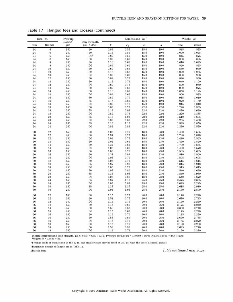
DUCTILE-IRON AND GRAY-IRON FITTINGS FOR WATER 39
Metric conversions: Iron strength: psi (1,000s) × 6.89 = MPa; Pressure rating: psi × 0.00689 = MPa; Dimension: in. × 25.4 = mm; Weight: lb × 0.4536 = kg.
*Fittings made of ductile iron in the 12-in. and smaller sizes may be rated at 350 psi with the use of a special gasket.
†Dimension details of flanges are in Table 14.
‡Ductile iron.
Table 17 Flanged tees and crosses (continued)
Size—in. Pressure Rating*
psiIron Strength
psi (1,000s)
Dimensions—in.† Weight—lb
Run Branch T T1 H J Tee Cross
24 6 150 30 0.89 0.55 15.0 19.0 845 87524 6 250 30 1.16 0.55 15.0 19.0 1,000 1,02524 6 250 DI‡ 0.89 0.55 15.0 19.0 845 87524 8 150 30 0.89 0.60 15.0 19.0 860 89524 8 250 30 1.16 0.60 15.0 19.0 1,010 1,04524 8 250 DI 0.89 0.60 15.0 19.0 860 89524 10 150 30 0.89 0.68 15.0 19.0 880 93024 10 250 30 1.16 0.68 15.0 19.0 1,020 1,06524 10 250 DI 0.89 0.68 15.0 19.0 880 93024 12 150 30 0.89 0.75 15.0 19.0 890 96024 12 250 30 1.16 0.75 15.0 19.0 1,040 1,10024 12 250 DI 0.89 0.75 15.0 19.0 890 96024 14 150 30 0.89 0.66 15.0 19.0 900 97524 14 250 30 1.16 0.82 15.0 19.0 1,050 1,12524 14 250 DI 0.89 0.66 15.0 19.0 900 97524 16 150 30 0.89 0.70 15.0 19.0 915 1,01024 16 250 35 1.16 0.89 15.0 19.0 1,070 1,16024 16 250 DI 0.89 0.70 15.0 19.0 915 1,01024 18 150 30 0.89 0.75 22.0 22.0 1,220 1,36524 18 250 35 1.16 0.96 22.0 22.0 1,470 1,62024 18 250 DI 0.89 0.75 22.0 22.0 1,220 1,36524 20 150 35 1.16 1.03 22.0 22.0 1,510 1,69524 20 250 DI 0.89 0.80 22.0 22.0 1,255 1,43024 24 150 35 1.16 1.16 22.0 22.0 1,585 1,85024 24 250 DI 0.89 0.89 22.0 22.0 1,330 1,570
30 12 150 30 1.03 0.75 18.0 23.0 1,490 1,56530 12 250 30 1.37 0.75 18.0 23.0 1,780 1,84020 12 250 DI 1.03 0.75 18.0 23.0 1,490 1,56530 14 150 30 1.03 0.66 18.0 23.0 1,490 1,57030 14 250 30 1.37 0.82 18.0 23.0 1,790 1,86530 14 250 DI 1.03 0.66 18.0 23.0 1,490 1,57030 16 150 30 1.03 0.70 18.0 23.0 1,505 1,60530 16 250 30 1.37 0.89 18.0 23.0 1,810 1,90030 16 250 DI 1.03 0.70 18.0 23.0 1,505 1,60530 18 150 30 1.03 0.75 18.0 23.0 1,515 1,61530 18 250 35 1.37 0.96 18.0 23.0 1,815 1,91030 18 250 DI 1.03 0.75 18.0 23.0 1,515 1,61530 20 150 30 1.03 0.80 18.0 23.0 1,540 1,67030 20 250 35 1.37 1.03 18.0 23.0 1,840 1,96030 20 250 DI 1.03 0.80 18.0 23.0 1,540 1,67030 24 150 35 1.37 1.16 25.0 25.0 2,475 2,69530 24 250 DI 1.03 0.89 25.0 25.0 2,025 2,24530 30 150 35 1.37 1.37 25.0 25.0 2,615 2,98030 30 250 DI 1.03 1.03 25.0 25.0 2,150 2,500
36 12 150 30 1.15 0.75 20.0 26.0 2,170 2,24036 12 250 30 1.58 0.75 20.0 26.0 2,670 2,72536 12 250 DI 1.15 0.75 20.0 26.0 2,170 2,24036 14 150 30 1.15 0.66 20.0 26.0 2,175 2,24036 14 250 30 1.58 0.82 20.0 26.0 2,680 2,74036 14 250 DI 1.15 0.66 20.0 26.0 2,175 2,24036 16 150 30 1.15 0.70 20.0 26.0 2,185 2,27036 16 250 30 1.58 0.89 20.0 26.0 2,690 2,76536 16 250 DI 1.15 0.70 20.0 26.0 2,185 2,27036 18 150 30 1.15 0.75 20.0 26.0 2,190 2,28036 18 250 30 1.58 0.96 20.0 26.0 2,695 2,77036 18 250 DI 1.15 0.75 20.0 26.0 2,190 2,280
Table continued next page.
Copyright © 1999 American Water Works Association, All Rights Reserved.
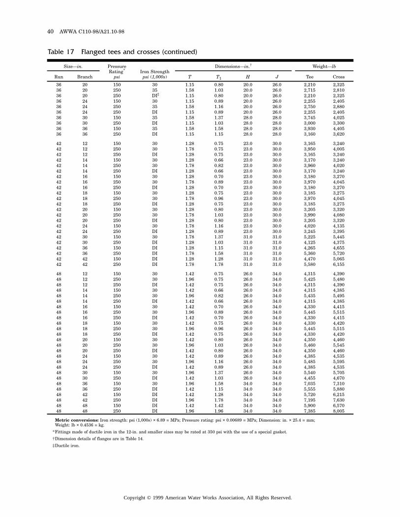
40 AWWA C110-98/A21.10-98
Metric conversions: Iron strength: psi (1,000s) × 6.89 = MPa; Pressure rating: psi × 0.00689 = MPa; Dimension: in. × 25.4 = mm; Weight: lb × 0.4536 = kg.
*Fittings made of ductile iron in the 12-in. and smaller sizes may be rated at 350 psi with the use of a special gasket.
†Dimension details of flanges are in Table 14.
‡Ductile iron.
Table 17 Flanged tees and crosses (continued)
Size—in. Pressure Rating*
psiIron Strength
psi (1,000s)
Dimensions—in.† Weight—lb
Run Branch T T1 H J Tee Cross
36 20 150 30 1.15 0.80 20.0 26.0 2,210 2,32536 20 250 35 1.58 1.03 20.0 26.0 2,715 2,81036 20 250 DI‡ 1.15 0.80 20.0 26.0 2,210 2,32536 24 150 30 1.15 0.89 20.0 26.0 2,255 2,40536 24 250 35 1.58 1.16 20.0 26.0 2,750 2,88036 24 250 DI 1.15 0.89 20.0 26.0 2,255 2,40536 30 150 35 1.58 1.37 28.0 28.0 3,745 4,02536 30 250 DI 1.15 1.03 28.0 28.0 3,000 3,30036 36 150 35 1.58 1.58 28.0 28.0 3,930 4,40536 36 250 DI 1.15 1.15 28.0 28.0 3,160 3,620
42 12 150 30 1.28 0.75 23.0 30.0 3,165 3,24042 12 250 30 1.78 0.75 23.0 30.0 3,950 4,00542 12 250 DI 1.28 0.75 23.0 30.0 3,165 3,24042 14 150 30 1.28 0.66 23.0 30.0 3,170 3,24042 14 250 30 1.78 0.82 23.0 30.0 3,960 4,02042 14 250 DI 1.28 0.66 23.0 30.0 3,170 3,24042 16 150 30 1.28 0.70 23.0 30.0 3,180 3,27042 16 250 30 1.78 0.89 23.0 30.0 3,970 4,04542 16 250 DI 1.28 0.70 23.0 30.0 3,180 3,27042 18 150 30 1.28 0.75 23.0 30.0 3,185 3,27542 18 250 30 1.78 0.96 23.0 30.0 3,970 4,04542 18 250 DI 1.28 0.75 23.0 30.0 3,185 3,27542 20 150 30 1.28 0.80 23.0 30.0 3,205 3,32042 20 250 30 1.78 1.03 23.0 30.0 3,990 4,08042 20 250 DI 1.28 0.80 23.0 30.0 3,205 3,32042 24 150 30 1.78 1.16 23.0 30.0 4,020 4,13542 24 250 DI 1.28 0.89 23.0 30.0 3,245 3,39542 30 150 30 1.78 1.37 31.0 31.0 5,225 5,44542 30 250 DI 1.28 1.03 31.0 31.0 4,125 4,37542 36 150 DI 1.28 1.15 31.0 31.0 4,265 4,65542 36 250 DI 1.78 1.58 31.0 31.0 5,360 5,72042 42 150 DI 1.28 1.28 31.0 31.0 4,470 5,06542 42 250 DI 1.78 1.78 31.0 31.0 5,580 6,155
48 12 150 30 1.42 0.75 26.0 34.0 4,315 4,39048 12 250 30 1.96 0.75 26.0 34.0 5,425 5,48048 12 250 DI 1.42 0.75 26.0 34.0 4,315 4,39048 14 150 30 1.42 0.66 26.0 34.0 4,315 4,38548 14 250 30 1.96 0.82 26.0 34.0 5,435 5,49548 14 250 DI 1.42 0.66 26.0 34.0 4,315 4,38548 16 150 30 1.42 0.70 26.0 34.0 4,330 4,41548 16 250 30 1.96 0.89 26.0 34.0 5,445 5,51548 16 250 DI 1.42 0.70 26.0 34.0 4,330 4,41548 18 150 30 1.42 0.75 26.0 34.0 4,330 4,42048 18 250 30 1.96 0.96 26.0 34.0 5,445 5,51548 18 250 DI 1.42 0.75 26.0 34.0 4,330 4,42048 20 150 30 1.42 0.80 26.0 34.0 4,350 4,46048 20 250 30 1.96 1.03 26.0 34.0 5,460 5,54548 20 250 DI 1.42 0.80 26.0 34.0 4,350 4,46048 24 150 30 1.42 0.89 26.0 34.0 4,385 4,53548 24 250 30 1.96 1.16 26.0 34.0 5,485 5,59548 24 250 DI 1.42 0.89 26.0 34.0 4,385 4,53548 30 150 30 1.96 1.37 26.0 34.0 5,540 5,70548 30 250 DI 1.42 1.03 26.0 34.0 4,455 4,67048 36 150 30 1.96 1.58 34.0 34.0 7,035 7,31048 36 250 DI 1.42 1.15 34.0 34.0 5,555 5,88048 42 150 DI 1.42 1.28 34.0 34.0 5,720 6,21548 42 250 DI 1.96 1.78 34.0 34.0 7,195 7,63048 48 150 DI 1.42 1.42 34.0 34.0 5,900 6,57048 48 250 DI 1.96 1.96 34.0 34.0 7,385 8,005
Copyright © 1999 American Water Works Association, All Rights Reserved.
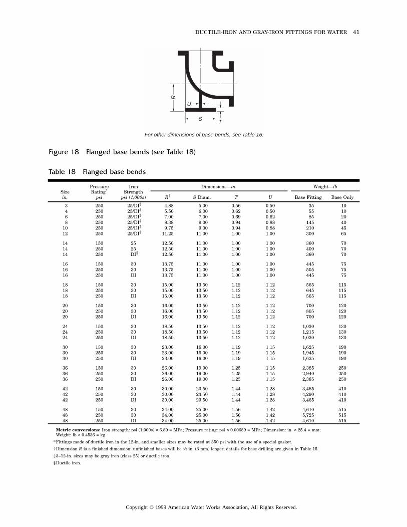
DUCTILE-IRON AND GRAY-IRON FITTINGS FOR WATER 41
For other dimensions of base bends, see Table 16.
S
U
T
R
Figure 18 Flanged base bends (see Table 18)
Metric conversions: Iron strength: psi (1,000s) × 6.89 = MPa; Pressure rating: psi × 0.00689 = MPa; Dimension: in. × 25.4 = mm; Weight: lb × 0.4536 = kg.
*Fittings made of ductile iron in the 12-in. and smaller sizes may be rated at 350 psi with the use of a special gasket.
†Dimension R is a finished dimension: unfinished bases will be 1⁄2 in. (3 mm) longer; details for base drilling are given in Table 15.
‡3–12-in. sizes may be gray iron (class 25) or ductile iron.
§Ductile iron.
Table 18 Flanged base bends
Sizein.
Pressure Rating*
psi
Iron Strength
psi (1,000s)
Dimensions—in. Weight—lb
R† S Diam. T U Base Fitting Base Only
3 250 25/DI‡ 4.88 5.00 0.56 0.50 35 104 250 25/DI‡ 5.50 6.00 0.62 0.50 55 106 250 25/DI‡ 7.00 7.00 0.69 0.62 85 208 250 25/DI‡ 8.38 9.00 0.94 0.88 145 40
10 250 25/DI‡ 9.75 9.00 0.94 0.88 210 4512 250 25/DI‡ 11.25 11.00 1.00 1.00 300 65
14 150 25 12.50 11.00 1.00 1.00 360 7014 250 25 12.50 11.00 1.00 1.00 400 7014 250 DI§ 12.50 11.00 1.00 1.00 360 70
16 150 30 13.75 11.00 1.00 1.00 445 7516 250 30 13.75 11.00 1.00 1.00 505 7516 250 DI 13.75 11.00 1.00 1.00 445 75
18 150 30 15.00 13.50 1.12 1.12 565 11518 250 30 15.00 13.50 1.12 1.12 645 11518 250 DI 15.00 13.50 1.12 1.12 565 115
20 150 30 16.00 13.50 1.12 1.12 700 12020 250 30 16.00 13.50 1.12 1.12 805 12020 250 DI 16.00 13.50 1.12 1.12 700 120
24 150 30 18.50 13.50 1.12 1.12 1,030 13024 250 30 18.50 13.50 1.12 1.12 1,215 13024 250 DI 18.50 13.50 1.12 1.12 1,030 130
30 150 30 23.00 16.00 1.19 1.15 1,625 19030 250 30 23.00 16.00 1.19 1.15 1,945 19030 250 DI 23.00 16.00 1.19 1.15 1,625 190
36 150 30 26.00 19.00 1.25 1.15 2,385 25036 250 30 26.00 19.00 1.25 1.15 2,940 25036 250 DI 26.00 19.00 1.25 1.15 2,385 250
42 150 30 30.00 23.50 1.44 1.28 3,465 41042 250 30 30.00 23.50 1.44 1.28 4,290 41042 250 DI 30.00 23.50 1.44 1.28 3,465 410
48 150 30 34.00 25.00 1.56 1.42 4,610 51548 250 30 34.00 25.00 1.56 1.42 5,725 51548 250 DI 34.00 25.00 1.56 1.42 4,610 515
Copyright © 1999 American Water Works Association, All Rights Reserved.
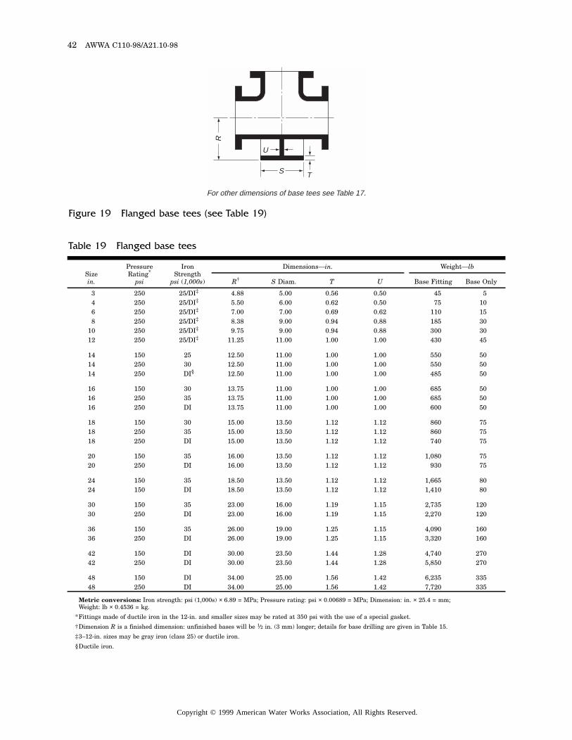
42 AWWA C110-98/A21.10-98
For other dimensions of base tees see Table 17.
S
U
T
RFigure 19 Flanged base tees (see Table 19)
Metric conversions: Iron strength: psi (1,000s) × 6.89 = MPa; Pressure rating: psi × 0.00689 = MPa; Dimension: in. × 25.4 = mm; Weight: lb × 0.4536 = kg.
*Fittings made of ductile iron in the 12-in. and smaller sizes may be rated at 350 psi with the use of a special gasket.
†Dimension R is a finished dimension: unfinished bases will be 1⁄2 in. (3 mm) longer; details for base drilling are given in Table 15.
‡3–12-in. sizes may be gray iron (class 25) or ductile iron.
§Ductile iron.
Table 19 Flanged base tees
Sizein.
Pressure Rating*
psi
Iron Strength
psi (1,000s)
Dimensions—in. Weight—lb
R† S Diam. T U Base Fitting Base Only
3 250 25/DI‡ 4.88 5.00 0.56 0.50 45 54 250 25/DI‡ 5.50 6.00 0.62 0.50 75 106 250 25/DI‡ 7.00 7.00 0.69 0.62 110 158 250 25/DI‡ 8.38 9.00 0.94 0.88 185 30
10 250 25/DI‡ 9.75 9.00 0.94 0.88 300 3012 250 25/DI‡ 11.25 11.00 1.00 1.00 430 45
14 150 25 12.50 11.00 1.00 1.00 550 5014 250 30 12.50 11.00 1.00 1.00 550 5014 250 DI§ 12.50 11.00 1.00 1.00 485 50
16 150 30 13.75 11.00 1.00 1.00 685 5016 250 35 13.75 11.00 1.00 1.00 685 5016 250 DI 13.75 11.00 1.00 1.00 600 50
18 150 30 15.00 13.50 1.12 1.12 860 7518 250 35 15.00 13.50 1.12 1.12 860 7518 250 DI 15.00 13.50 1.12 1.12 740 75
20 150 35 16.00 13.50 1.12 1.12 1,080 7520 250 DI 16.00 13.50 1.12 1.12 930 75
24 150 35 18.50 13.50 1.12 1.12 1,665 8024 150 DI 18.50 13.50 1.12 1.12 1,410 80
30 150 35 23.00 16.00 1.19 1.15 2,735 12030 250 DI 23.00 16.00 1.19 1.15 2,270 120
36 150 35 26.00 19.00 1.25 1.15 4,090 16036 250 DI 26.00 19.00 1.25 1.15 3,320 160
42 150 DI 30.00 23.50 1.44 1.28 4,740 27042 250 DI 30.00 23.50 1.44 1.28 5,850 270
48 150 DI 34.00 25.00 1.56 1.42 6,235 33548 250 DI 34.00 25.00 1.56 1.42 7,720 335
Copyright © 1999 American Water Works Association, All Rights Reserved.
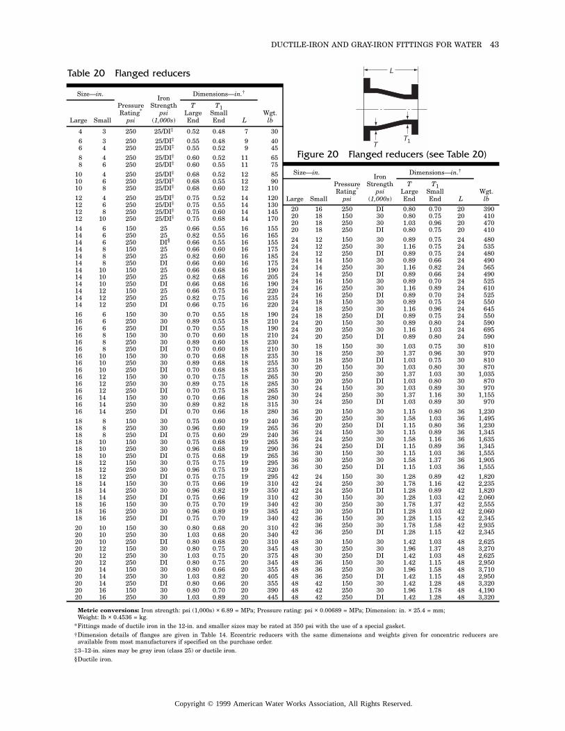
DUCTILE-IRON AND GRAY-IRON FITTINGS FOR WATER 43
Table 20 Flanged reducers
Size—in.
Pressure Rating*
psi
Iron Strength
psi(1,000s)
Dimensions—in.†
Wgt.lbLarge Small
TLarge End
T1Small End L
4 3 250 25/DI‡ 0.52 0.48 7 306 3 250 25/DI‡ 0.55 0.48 9 406 4 250 25/DI‡ 0.55 0.52 9 458 4 250 25/DI‡ 0.60 0.52 11 658 6 250 25/DI‡ 0.60 0.55 11 75
10 4 250 25/DI‡ 0.68 0.52 12 8510 6 250 25/DI‡ 0.68 0.55 12 9010 8 250 25/DI‡ 0.68 0.60 12 11012 4 250 25/DI‡ 0.75 0.52 14 12012 6 250 25/DI‡ 0.75 0.55 14 13012 8 250 25/DI‡ 0.75 0.60 14 14512 10 250 25/DI‡ 0.75 0.68 14 17014 6 150 25 0.66 0.55 16 15514 6 250 25 0.82 0.55 16 16514 6 250 DI§ 0.66 0.55 16 15514 8 150 25 0.66 0.60 16 17514 8 250 25 0.82 0.60 16 18514 8 250 DI 0.66 0.60 16 17514 10 150 25 0.66 0.68 16 19014 10 250 25 0.82 0.68 16 20514 10 250 DI 0.66 0.68 16 19014 12 150 25 0.66 0.75 16 22014 12 250 25 0.82 0.75 16 23514 12 250 DI 0.66 0.75 16 22016 6 150 30 0.70 0.55 18 19016 6 250 30 0.89 0.55 18 21016 6 250 DI 0.70 0.55 18 19016 8 150 30 0.70 0.60 18 21016 8 250 30 0.89 0.60 18 23016 8 250 DI 0.70 0.60 18 21016 10 150 30 0.70 0.68 18 23516 10 250 30 0.89 0.68 18 25516 10 250 DI 0.70 0.68 18 23516 12 150 30 0.70 0.75 18 26516 12 250 30 0.89 0.75 18 28516 12 250 DI 0.70 0.75 18 26516 14 150 30 0.70 0.66 18 28016 14 250 30 0.89 0.82 18 31516 14 250 DI 0.70 0.66 18 28018 8 150 30 0.75 0.60 19 24018 8 250 30 0.96 0.60 19 26518 8 250 DI 0.75 0.60 29 24018 10 150 30 0.75 0.68 19 26518 10 250 30 0.96 0.68 19 29018 10 250 DI 0.75 0.68 19 26518 12 150 30 0.75 0.75 19 29518 12 250 30 0.96 0.75 19 32018 12 250 DI 0.75 0.75 19 29518 14 150 30 0.75 0.66 19 31018 14 250 30 0.96 0.82 19 35018 14 250 DI 0.75 0.66 19 31018 16 150 30 0.75 0.70 19 34018 16 250 30 0.96 0.89 19 38518 16 250 DI 0.75 0.70 19 34020 10 150 30 0.80 0.68 20 31020 10 250 30 1.03 0.68 20 34020 10 250 DI 0.80 0.68 20 31020 12 150 30 0.80 0.75 20 34520 12 250 30 1.03 0.75 20 37520 12 250 DI 0.80 0.75 20 34520 14 150 30 0.80 0.66 20 35520 14 250 30 1.03 0.82 20 40520 14 250 DI 0.80 0.66 20 35520 16 150 30 0.80 0.70 20 39020 16 250 30 1.03 0.89 20 445
Size—in.
Pressure Rating*
psi
Iron Strength
psi(1,000s)
Dimensions—in.†
Wgt.lbLarge Small
TLarge End
T1Small End L
20 16 250 DI 0.80 0.70 20 39020 18 150 30 0.80 0.75 20 41020 18 250 30 1.03 0.96 20 47020 18 250 DI 0.80 0.75 20 41024 12 150 30 0.89 0.75 24 48024 12 250 30 1.16 0.75 24 53524 12 250 DI 0.89 0.75 24 48024 14 150 30 0.89 0.66 24 49024 14 250 30 1.16 0.82 24 56524 14 250 DI 0.89 0.66 24 49024 16 150 30 0.89 0.70 24 52524 16 250 30 1.16 0.89 24 61024 16 250 DI 0.89 0.70 24 52524 18 150 30 0.89 0.75 24 55024 18 250 30 1.16 0.96 24 64524 18 250 DI 0.89 0.75 24 55024 20 150 30 0.89 0.80 24 59024 20 250 30 1.16 1.03 24 69524 20 250 DI 0.89 0.80 24 59030 18 150 30 1.03 0.75 30 81030 18 250 30 1.37 0.96 30 97030 18 250 DI 1.03 0.75 30 81030 20 150 30 1.03 0.80 30 87030 20 250 30 1.37 1.03 30 1,03530 20 250 DI 1.03 0.80 30 87030 24 150 30 1.03 0.89 30 97030 24 250 30 1.37 1.16 30 1,15530 24 250 DI 1.03 0.89 30 97036 20 150 30 1.15 0.80 36 1,23036 20 250 30 1.58 1.03 36 1,49536 20 250 DI 1.15 0.80 36 1,23036 24 150 30 1.15 0.89 36 1,34536 24 250 30 1.58 1.16 36 1,63536 24 250 DI 1.15 0.89 36 1,34536 30 150 30 1.15 1.03 36 1,55536 30 250 30 1.58 1.37 36 1,90536 30 250 DI 1.15 1.03 36 1,55542 24 150 30 1.28 0.89 42 1,82042 24 250 30 1.78 1.16 42 2,23542 24 250 DI 1.28 0.89 42 1,82042 30 150 30 1.28 1.03 42 2,06042 30 250 30 1.78 1.37 42 2,55542 30 250 DI 1.28 1.03 42 2,06042 36 150 30 1.28 1.15 42 2,34542 36 250 30 1.78 1.58 42 2,93542 36 250 DI 1.28 1.15 42 2,34548 30 150 30 1.42 1.03 48 2,62548 30 250 30 1.96 1.37 48 3,27048 30 250 DI 1.42 1.03 48 2,62548 36 150 30 1.42 1.15 48 2,95048 36 250 30 1.96 1.58 48 3,71048 36 250 DI 1.42 1.15 48 2,95048 42 150 30 1.42 1.28 48 3,32048 42 250 30 1.96 1.78 48 4,19048 42 250 DI 1.42 1.28 48 3,320
L
TT1
Figure 20 Flanged reducers (see Table 20)
Metric conversions: Iron strength: psi (1,000s) × 6.89 = MPa; Pressure rating: psi × 0.00689 = MPa; Dimension: in. × 25.4 = mm; Weight: lb × 0.4536 = kg.
*Fittings made of ductile iron in the 12-in. and smaller sizes may be rated at 350 psi with the use of a special gasket.†Dimension details of flanges are given in Table 14. Eccentric reducers with the same dimensions and weights given for concentric reducers are
available from most manufacturers if specified on the purchase order.‡3–12-in. sizes may be gray iron (class 25) or ductile iron.§Ductile iron.
Copyright © 1999 American Water Works Association, All Rights Reserved.

This page intentionally blank.
Copyright © 1999 American Water Works Association, All Rights Reserved.
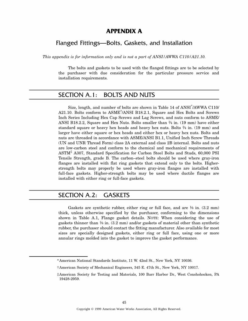
APPENDIX A
Flanged Fittings—Bolts, Gaskets, and Installation
This appendix is for information only and is not a part of ANSI/AWWA C110/A21.10.
The bolts and gaskets to be used with the flanged fittings are to be selected bythe purchaser with due consideration for the particular pressure service andinstallation requirements.
SECTION A.1: BOLTS AND NUTS
Size, length, and number of bolts are shown in Table 14 of ANSI*/AWWA C110/A21.10. Bolts conform to ASME†/ANSI B18.2.1, Square and Hex Bolts and ScrewsInch Series Including Hex Cap Screws and Lag Screws, and nuts conform to ASME/ANSI B18.2.2, Square and Hex Nuts. Bolts smaller than 3⁄4 in. (19 mm) have eitherstandard square or heavy hex heads and heavy hex nuts. Bolts 3⁄4 in. (19 mm) andlarger have either square or hex heads and either hex or heavy hex nuts. Bolts andnuts are threaded in accordance with ASME/ANSI B1.1, Unified Inch Screw Threads(UN and UNR Thread Form) class 2A external and class 2B internal. Bolts and nutsare low-carbon steel and conform to the chemical and mechanical requirements ofASTM‡ A307, Standard Specification for Carbon Steel Bolts and Studs, 60,000 PSITensile Strength, grade B. The carbon–steel bolts should be used where gray-ironflanges are installed with flat ring gaskets that extend only to the bolts. Higher-strength bolts may properly be used where gray-iron flanges are installed withfull-face gaskets. Higher-strength bolts may be used where ductile flanges areinstalled with either ring or full-face gaskets.
SECTION A.2: GASKETS
Gaskets are synthetic rubber, either ring or full face, and are 1⁄8 in. (3.2 mm)thick, unless otherwise specified by the purchaser, conforming to the dimensionsshown in Table A.1, Flange gasket details. NOTE: When considering the use ofgaskets thinner than 1⁄8 in. (3.2 mm) and/or gaskets of material other than syntheticrubber, the purchaser should contact the fitting manufacturer. Also available for mostsizes are specially designed gaskets, either ring or full face, using one or moreannular rings molded into the gasket to improve the gasket performance.
*American National Standards Institute, 11 W. 42nd St., New York, NY 10036.
†American Society of Mechanical Engineers, 345 E. 47th St., New York, NY 10017.
‡American Society for Testing and Materials, 100 Barr Harbor Dr., West Conshohocken, PA19428-2959.
45
Copyright © 1999 American Water Works Association, All Rights Reserved.
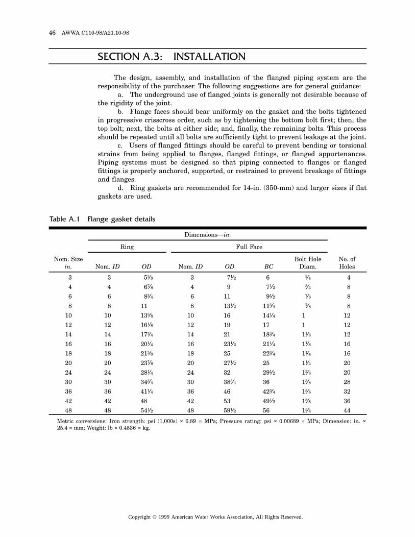
46 AWWA C110-98/A21.10-98
SECTION A.3: INSTALLATION
The design, assembly, and installation of the flanged piping system are theresponsibility of the purchaser. The following suggestions are for general guidance:
a. The underground use of flanged joints is generally not desirable because ofthe rigidity of the joint.
b. Flange faces should bear uniformly on the gasket and the bolts tightenedin progressive crisscross order, such as by tightening the bottom bolt first; then, thetop bolt; next, the bolts at either side; and, finally, the remaining bolts. This processshould be repeated until all bolts are sufficiently tight to prevent leakage at the joint.
c. Users of flanged fittings should be careful to prevent bending or torsionalstrains from being applied to flanges, flanged fittings, or flanged appurtenances.Piping systems must be designed so that piping connected to flanges or flangedfittings is properly anchored, supported, or restrained to prevent breakage of fittingsand flanges.
d. Ring gaskets are recommended for 14-in. (350-mm) and larger sizes if flatgaskets are used.
Metric conversions: Iron strength: psi (1,000s) × 6.89 = MPa; Pressure rating: psi × 0.00689 = MPa; Dimension: in. ×25.4 = mm; Weight: lb × 0.4536 = kg.
Table A.1 Flange gasket details
Nom. Sizein.
Dimensions—in.
No. of Holes
Ring Full Face
Nom. ID OD Nom. ID OD BCBolt Hole
Diam.
3 3 53⁄8 3 71⁄2 6 3⁄4 4
4 4 67⁄8 4 9 71⁄2 3⁄4 8
6 6 83⁄4 6 11 91⁄2 7⁄8 8
8 8 11 8 131⁄2 113⁄4 7⁄8 8
10 10 133⁄8 10 16 141⁄4 1 12
12 12 161⁄8 12 19 17 1 12
14 14 173⁄4 14 21 183⁄4 11⁄8 12
16 16 201⁄4 16 231⁄2 211⁄4 11⁄8 16
18 18 215⁄8 18 25 223⁄4 11⁄4 16
20 20 237⁄8 20 271⁄2 25 11⁄4 20
24 24 281⁄4 24 32 291⁄2 13⁄8 20
30 30 343⁄4 30 383⁄4 36 13⁄8 28
36 36 411⁄4 36 46 423⁄4 15⁄8 32
42 42 48 42 53 491⁄2 15⁄8 36
48 48 541⁄2 48 591⁄2 56 15⁄8 44
Copyright © 1999 American Water Works Association, All Rights Reserved.
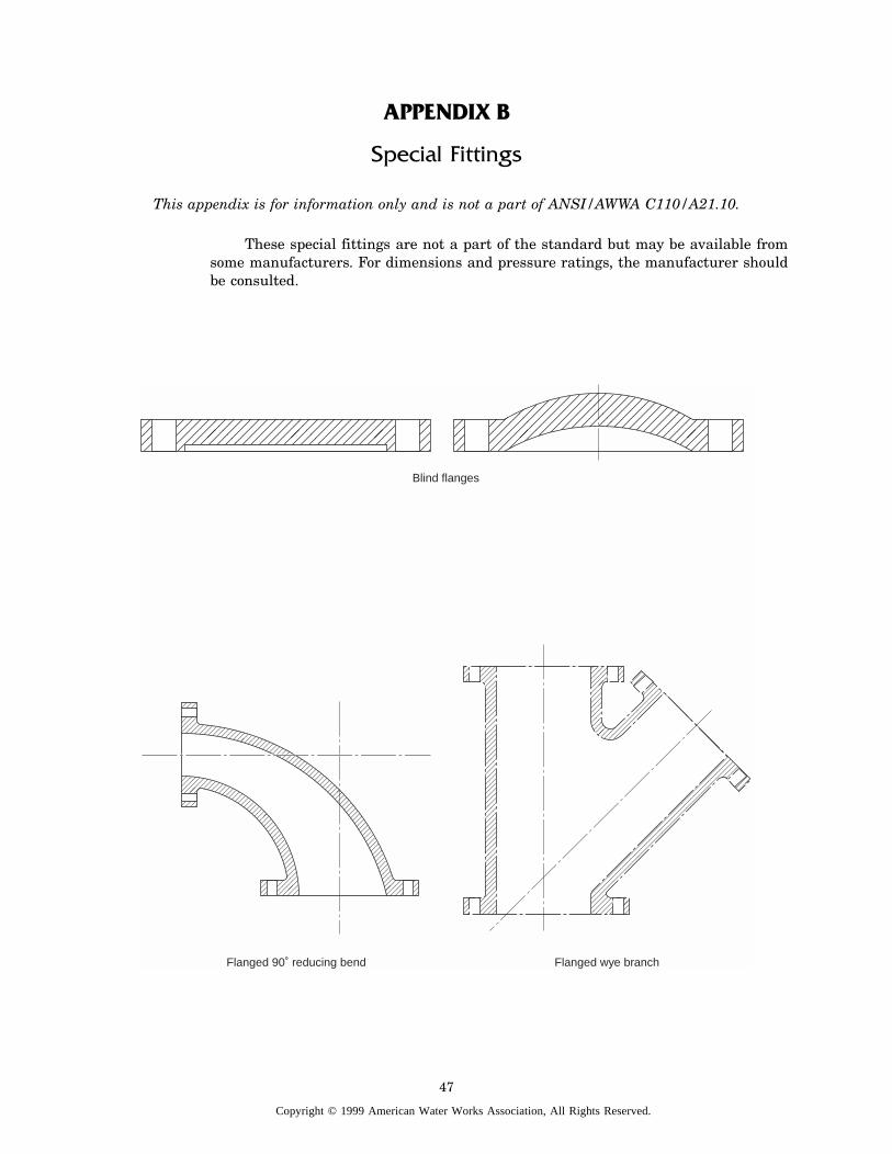
APPENDIX B
Special Fittings
This appendix is for information only and is not a part of ANSI/AWWA C110/A21.10.
These special fittings are not a part of the standard but may be available fromsome manufacturers. For dimensions and pressure ratings, the manufacturer shouldbe consulted.
��
���
���
���
Blind flanges
Flanged 90˚ reducing bend Flanged wye branch
��
���
���
����
���
�����
�������
���������
����������
���������
�������
�����
���
���
�����
�������
���������
�����������
������������
�����������
���������
�������
�����
����
47
Copyright © 1999 American Water Works Association, All Rights Reserved.
48 AWWA C110-98/A21.10-98
Flange and flare 90˚ bend
Flanged bullhead tee
Mechanical-joint wye branch ��
����
������
��������
����������
����������
���������
�������
�����
���
��
����
������
��������
����������
���������
��������
������
����
��
����
�����
�������
���������
����������
����������
��������
������
����
��
����
�����
�������
���������
���������
��������
������
����
��
Flange and flare
Flanged reducing tee
Flanged true wye
����
�����
�������
���������
�����������
������������
������������
����������
��������
������
����
��
���
�����
�������
���������
�����������
������������
������������
�����������
���������
�������
�����
���
��
��
��
��
��
��
��������������
Copyright © 1999 American Water Works Association, All Rights Reserved.
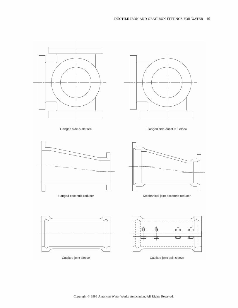
DUCTILE-IRON AND GRAY-IRON FITTINGS FOR WATER 49
Caulked-joint split sleeve
Mechanical-joint eccentric reducer
Flanged side-outlet 90˚ elbow
Caulked-joint sleeve
Flanged eccentric reducer
Flanged side-outlet tee
Copyright © 1999 American Water Works Association, All Rights Reserved.
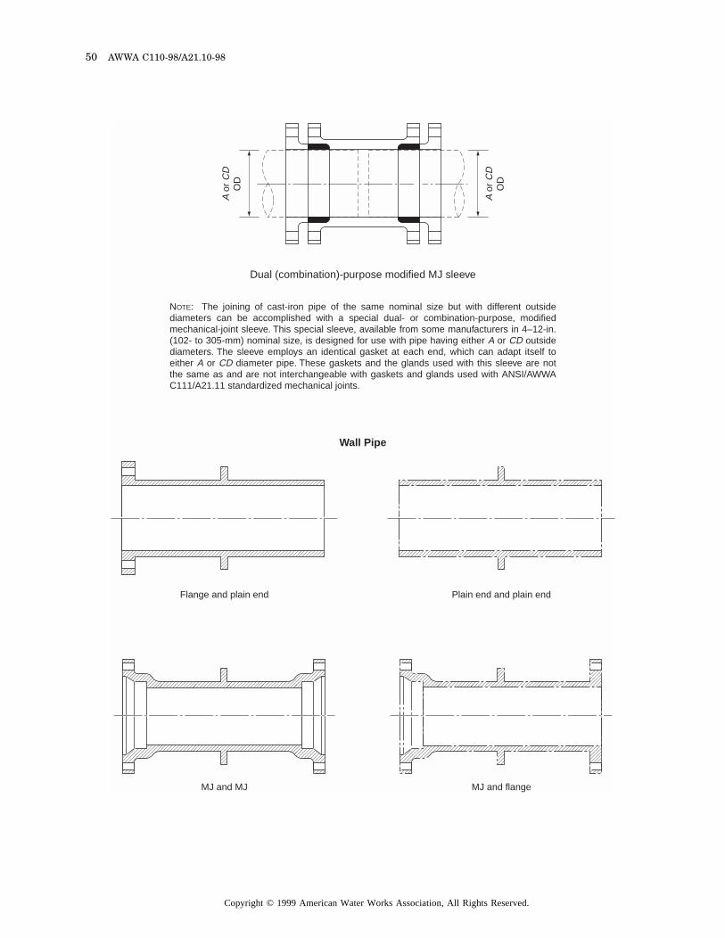
50 AWWA C110-98/A21.10-98
Wall Pipe
Dual (combination)-purpose modified MJ sleeve
NOTE: The joining of cast-iron pipe of the same nominal size but with different outside diameters can be accomplished with a special dual- or combination-purpose, modified mechanical-joint sleeve. This special sleeve, available from some manufacturers in 4–12-in. (102- to 305-mm) nominal size, is designed for use with pipe having either A or CD outside diameters. The sleeve employs an identical gasket at each end, which can adapt itself to either A or CD diameter pipe. These gaskets and the glands used with this sleeve are not the same as and are not interchangeable with gaskets and glands used with ANSI/AWWA C111/A21.11 standardized mechanical joints.
MJ and flangeMJ and MJ ��
����
������
��������
���������
���������
��������
�������
�����
���
Flange and plain end ��
����
������
��������
���������
���������
��������
�������
�����
����
Plain end and plain end ��
����
������
��������
���������
���������
��������
�������
�����
���
��
����
������
��������
���������
���������
��������
�������
�����
���
A o
r C
DO
D
A o
r C
DO
D
Copyright © 1999 American Water Works Association, All Rights Reserved.
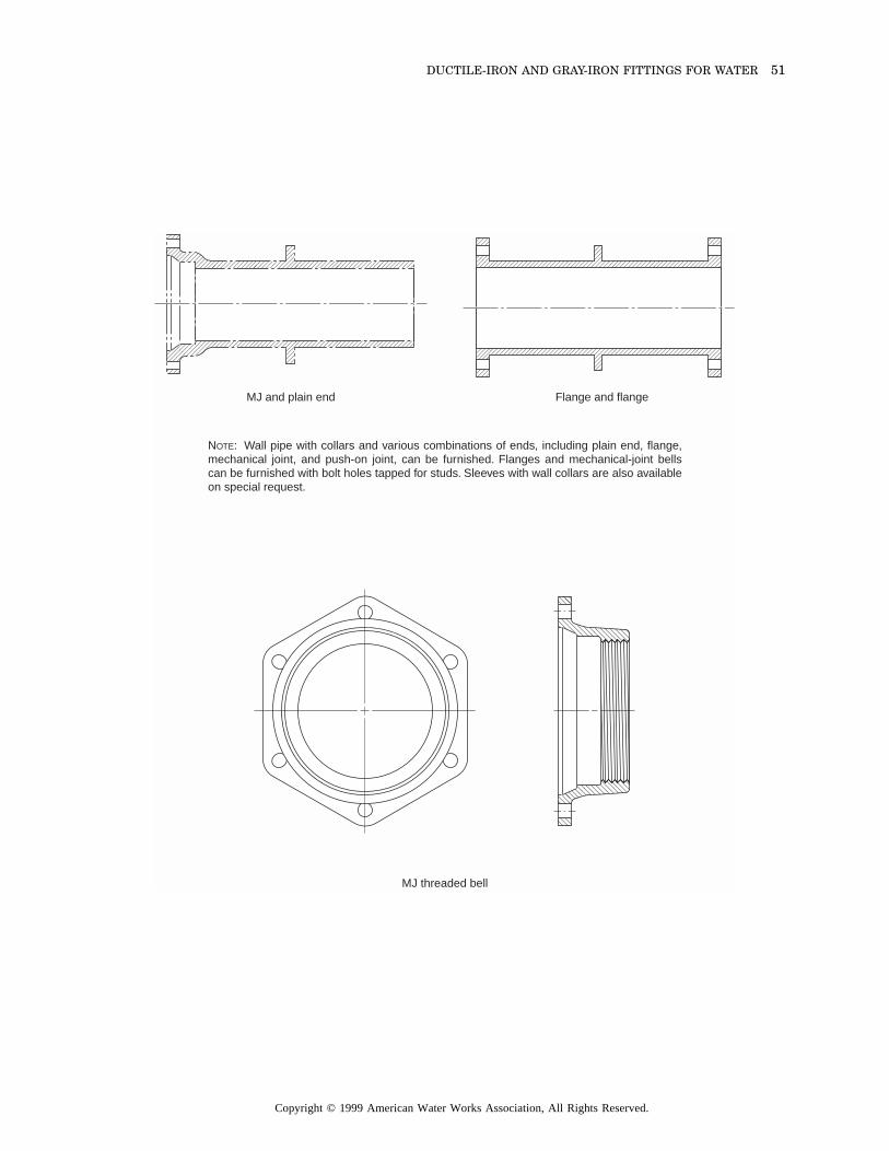
DUCTILE-IRON AND GRAY-IRON FITTINGS FOR WATER 51
NOTE: Wall pipe with collars and various combinations of ends, including plain end, flange, mechanical joint, and push-on joint, can be furnished. Flanges and mechanical-joint bells can be furnished with bolt holes tapped for studs. Sleeves with wall collars are also available on special request.
MJ threaded bell
��
����
������
��������
���������
���������
��������
�������
�����
����
MJ and plain end Flange and flange��
����
������
��������
���������
���������
��������
�������
�����
���
���
����
�����
�����
�����
����
��
Copyright © 1999 American Water Works Association, All Rights Reserved.

This page intentionally blank.
Copyright © 1999 American Water Works Association, All Rights Reserved.

This page intentionally blank.
Copyright © 1999 American Water Works Association, All Rights Reserved.

1P-7.5M-43110-5/99-CM Printed on recycled paper.
Copyright © 1999 American Water Works Association, All Rights Reserved.