c2r summerfall 2011
TRANSCRIPT

8/10/2019 C2R SummerFall 2011
http://slidepdf.com/reader/full/c2r-summerfall-2011 1/24
An PublicationAltair S U M M E R / F A L L 2 0 1
4 Simulation StreamlinesAircraft Door Development
8 Bird Strike Simulation
Takes Flight
17 Inside a NASA Production
Supercomputing Center
Ideas and Strategies In Product Development

8/10/2019 C2R SummerFall 2011
http://slidepdf.com/reader/full/c2r-summerfall-2011 2/24
Cradle North America Inc.70 Birch Alley Suite 240, Beavercreek, OH 45440
Phone: +1-937-912-5798 Fax: +1-513-672-0523 [email protected]
Why Cradle CFDWhy Cradle CFD
Access SC/Tetra & STRThrough Altair HyperW
Choosing CFD software is a crucial step of a long termcommitment. The last thing you want after investing in
personnel, training, and hardware, is to discover that the
software you chose won’t do what you need it to do. Here
seven reasons why Cradle’s SC/Tetra and STREAM CFD
software should be considered as part of your due diligen
Thermofluid Analysis System
with Unstructured Mesh
Thermofluid Analysis Systemwith Structured Mesh
Increase Your Confidence that
You’re Committing to the
Right CFD Software
Cradle software were
originally designed to work
on Windows PC and
not converted from UNIX.
This makes Cradle software
very efficient and capableeven when using standard PC
equipment.
Windows compatible7Cradle customers include
Canon, Panasonic, Sony,
Yamaha, Toyota, and many
others in the United States,
Canada and Asia Pacific.
Used by recognized
global companies6
Both offer full general
purpose functionality
including free-surface,
humidity/condensation, and
moving meshes. SC/Tetra
also simulates fully coupled
Human Body
Thermoregulation andCavitation.
The CFD committee (ed.), Geometry Da
Model Vehicle Used in Wind Tunnel Tes
for Prospective CFD Benchmark Tests
Japanese), Technical Report Series, JS
No.42, (2008).
General purpose
CFD software1Each contains
pre-processor, solver, and
post-processor sharing
common user-friendly
interfaces and providing
seamless integration.
SC/Tetra eliminates the need
to purchase additional 3rd
party grid software.
All inclusive2SC/Tetra unstructured grid
CFD software is used when
accurately modeling arbitrary
shapes and complex curved
surfaces is important.
STREAM structured grid CFD
software is used when fine
geometrical details are lessinfluential.
Unstructured and
structured grid products3
The Japanese Society of
Automotive Engineers (JSAE)
collected drag and lift data
for a 1/5 scale vehicle1 and
provided a 3D computer
model to CFD developers to
determine how well CFD can
predict zero degree yaw drag
and lift. SC/Tetra predicted
both CD and C
L within 1% of
the measured values 2.
Proven accuracy5
ThermofluidAnalysisSystem
withUnstructur edMesh
ThermofluidAnalysisSystem
withStructured Mesh
Ultra-low memory
consumption solver (5M
cell/GB of RAM) facilitates
running higher resolution
models.
4 Low memory consumpt
and fast solver
1
Shimano, K. Et al., Wind Tunnel Testing
JSAE Standard Low- aerodynamic-drag
Vehicle Body Using 1/5 Scale Model,
Review of Automotive Engineering, Vo
No.1, (2009).
2
http://www.cradle-cfd.c
Cradle North America Inc.
70 Birch Alley Suite 240, Beavercreek, OH 45440
Phone: +1-937-912-5798 Fax: +1-513-672-0523 [email protected]
Why Cradle CFDWhy Cradle CFD
Access SC/Tetra & STREAThrough Altair HyperWo
Choosing CFD software is a crucial step of a long term
commitment. The last thing you want after investing in
personnel, training, and hardware, is to discover that the C
software you chose won’t do what you need it to do. Here a
seven reasons why Cradle’s SC/Tetra and STREAM CFD
software should be considered as part of your due diligenc
Thermofluid Analysis System
with Unstructured Mesh
Thermofluid Analysis System
with Structured Mesh
Increase Your Confidence that
You’re Committing to the
Right CFD Software
Cradle software were
originally designed to work
on Windows PC and
not converted from UNIX.
This makes Cradle software
very efficient and capable
even when using standard PC
equipment.
Windows compatible7Cradle customers include
Canon, Panasonic, Sony,
Yamaha, Toyota, and many
others in the United States,
Canada and Asia Pacific.
Used by recognized
global companies6
Both offer full general
purpose functionality
including free-surface,
humidity/condensation, and
moving meshes. SC/Tetra
also simulates fully coupled
Human BodyThermoregulation and
Cavitation.
The CFD committee (ed.), Geometry Data
Model Vehicle Used in Wind Tunnel Testin
for Prospective CFD Benchmark Tests (in
Japanese), Technical Report Series, JSAE
No.42, (2008).
General purpose
CFD software1Each contains
pre-processor, solver, and
post-processor sharing
common user-friendly
interfaces and providing
seamless integration.
SC/Tetra eliminates the needto purchase additional 3rd
party grid software.
All inclusive2SC/Tetra unstructured grid
CFD software is used when
accurately modeling arbitrary
shapes and complex curved
surfaces is important.
STREAM structured grid CFD
software is used when finegeometrical details are less
influential.
Unstructured and
structured grid products3
The Japanese Society of
Automotive Engineers (JSAE)
collected drag and lift data
for a 1/5 scale vehicle1 and
provided a 3D computer
model to CFD developers todetermine how well CFD can
predict zero degree yaw drag
and lift. SC/Tetra predicted
both CD and C
L within 1% of
the measured values 2.
Proven accuracy5
ThermofluidAnalysisSystem
withUnstructuredMesh
ThermofluidAnalysis System
withSt ructuredMesh
Ultra-low memory
consumption solver (5M
cell/GB of RAM) facilitates
running higher resolution
models.
4 Low memory consumptio
and fast solver
1
Shimano, K. Et al., Wind Tunnel Testing of
JSAE Standard Low- aerodynamic-drag
Vehicle Body Using 1/5 Scale Model,
Review of Automotive Engineering, Vol. 3
No.1, (2009).
2
http://www.cradle-cfd.com
Cradle North America Inc.
70 Birch Alley Suite 240, Beavercreek, OH 45440
Phone: +1-937-912-5798 Fax: +1-513-672-0523 [email protected]
Why Cradle CFDWhy Cradle CFD
Access SC/Tetra & STRThrough Altair HyperW
Choosing CFD software is a crucial step of a long term
commitment. The last thing you want after investing in
personnel, training, and hardware, is to discover that the
software you chose won’t do what you need it to do. Here
seven reasons why Cradle’s SC/Tetra and STREAM CFD
software should be considered as part of your due dilige
Thermofluid Analysis System
with Unstructured Mesh
Thermofluid Analysis System
with Structured Mesh
Increase Your Confidence that
You’re Committing to the
Right CFD Software
Cradle software were
originally designed to work
on Windows PC and
not converted from UNIX.
This makes Cradle software
very efficient and capable
even when using standard PC
equipment.
Windows compatible7Cradle customers include
Canon, Panasonic, Sony,
Yamaha, Toyota, and many
others in the United States,
Canada and Asia Pacific.
Used by recognized
global companies6
Both offer full general
purpose functionality
including free-surface,
humidity/condensation, and
moving meshes. SC/Tetra
also simulates fully coupled
Human BodyThermoregulation and
Cavitation.
The CFD committee (ed.), Geometry D
Model Vehicle Used in Wind Tunnel Te
for Prospective CFD Benchmark Tests
Japanese), Technical Report Series, J
No.42, (2008).
General purpose
CFD software1Each contains
pre-processor, solver, and
post-processor sharing
common user-friendly
interfaces and providing
seamless integration.
SC/Tetra eliminates the needto purchase additional 3rd
party grid software.
All inclusive2SC/Tetra unstructured grid
CFD software is used when
accurately modeling arbitrary
shapes and complex curved
surfaces is important.
STREAM structured grid CFD
software is used when finegeometrical details are less
influential.
Unstructured and
structured grid products3
The Japanese Society of
Automotive Engineers (JSAE)
collected drag and lift data
for a 1/5 scale vehicle1 and
provided a 3D computer
model to CFD developers todetermine how well CFD can
predict zero degree yaw drag
and lift. SC/Tetra predicted
both CD and C
L within 1% of
the measured values 2.
Proven accuracy5
ThermofluidAnalysis System
withUnstructuredMesh
ThermofluidAnalysis System
withStructuredMesh
Ultra-low memory
consumption solver (5M
cell/GB of RAM) facilitates
running higher resolution
models.
4 Low memory consump
and fast solver
1
Shimano, K. Et al., Wind Tunnel Testin
JSAE Standard Low- aerodynamic-dra
Vehicle Body Using 1/5 Scale Model,
Review of Automotive Engineering, Vo
No.1, (2009).
2
http://www.cradle-cfd.co

8/10/2019 C2R SummerFall 2011
http://slidepdf.com/reader/full/c2r-summerfall-2011 3/24
8/10/2019 C2R SummerFall 2011
http://slidepdf.com/reader/full/c2r-summerfall-2011 4/24
Landing Success with
Simulation and Optimization
James R. ScapaChairman and CEO,
Altair Engineering, Inc.
Over the last few years, Altair Engineering, Inc. has continued to expand its business. This
year, we are on track to earn over $200 million in revenue, representing a 20% increase
over last year. We attribute this performance to steady growth in markets where we are the
market share leader, such as automotive, as well as growth that is outpacing the industry in
advanced manufacturing segments such as aerospace, shipbuilding, marine, heavy industry and rail.
In fact, aerospace represents our fastest growing market. In 2011, we anticipate an annual growth
rate of 35% as we help customers employ simulation and optimization techniques to develop products
ranging from innovative jet engines to lightweight aircraft structures. Our HyperWorks analysis solu-
tions enable engineers to rapidly analyze, explore and optimize designs to dramatically reduce develop-
ment time and costs.
To assist aerospace and other customers meet both engineering and business challenges, Altair is
investing in several areas. With regard to modeling, visualization and automation, we recently acquired
SimLab, a process-oriented, feature-based, finite-element modeling software for solid structures. With
productivity gains in excess of five times for certain classes of problems, we will be working to identify
opportunities to leverage this technology and philosophy more broadly through our product offerings.
To address simulation, data capture and data management issues, we recently introduced collabora-
tion tools in HyperWorks 11.0. These capabilities bring an intuitive, user-centric experience for manag-
ing personal and team CAE data and processes without leaving the HyperWorks environment. We see
providing immediate productivity benefits to our HyperWorks community, without impacting current
CAE workflow processes, as an integral step towards evolving an enterprise simulation data managementstrategy.
In the realms of predictive analytics and optimization, we are adding evermore robust features to
RADIOSS, OptiStruct and MotionSolve. Through our acquisition of ACUSIM and its AcuSolve
computational fluid dynamics (CFD) technology, HyperWorks now offers a powerful portfolio of solvers
for linear, nonlinear, multi-body dynamics and CFD problems. AcuSolve uniquely provides the added
advantage of being tightly integrated with our structural analysis and optimization solutions to allow our
customers to solve complex fluid-structure interaction and multi-physics problems.
With respect to technology that addresses our customers’ business challenges, we continue to invest
heavily in PBS Works, our suite of on-demand cloud computing technologies for maximizing computing
infrastructure assets. Leveraging this platform, we just introduced HyperWorks On-Demand, a solution
that leverages our patented licensing system to provide access to HyperWorks and a scalable high-per-
formance computing infrastructure through a secure Web-based platform. In addition, we are providing
organizations with unparalleled decision-making power through our HiQube business intelligence solu-tions, which deliver in-depth business analytics and reporting capabilities for the largest data sets.
Through the unique combination of our people, best-in-class simulation technology, open-architec-
ture system and our patented HyperWorks Unit business model, Altair provides customers with the tools
to take their businesses to new heights – and land success.
Altair focuses on simulation, predictive analytics andoptimization, leveraging high-performance computing that
promotes innovative engineering and business decision-making.
www.altair.com/c
2Concept To Reality Summer/Fall 2011
L E T T E R F R O M T H E C E O

8/10/2019 C2R SummerFall 2011
http://slidepdf.com/reader/full/c2r-summerfall-2011 5/24
Software
Altair delivers design, engineering and analytics
software that balances performance, weight and
cost so companies can create more advanced,
protable products.
Consulting
By combining its technology with a deep
understanding of the product life cycle,
Altair collaborates with clients to develop
products that are sustainable from the start.
Delivering Solutions for
High-performance Products
Attention aerospace community!
Complete a short, online survey for a chance to win
an iPad at www.altair.com/C2Raerosurvey
HyperWorks | Altair ProductDesign | PBS Works | solidThinking | HiQube | ilum
8/10/2019 C2R SummerFall 2011
http://slidepdf.com/reader/full/c2r-summerfall-2011 6/24www.altair.com/c
4Concept To Reality Summer/Fall 2011
P R O C E S S A U T O M A T I O N
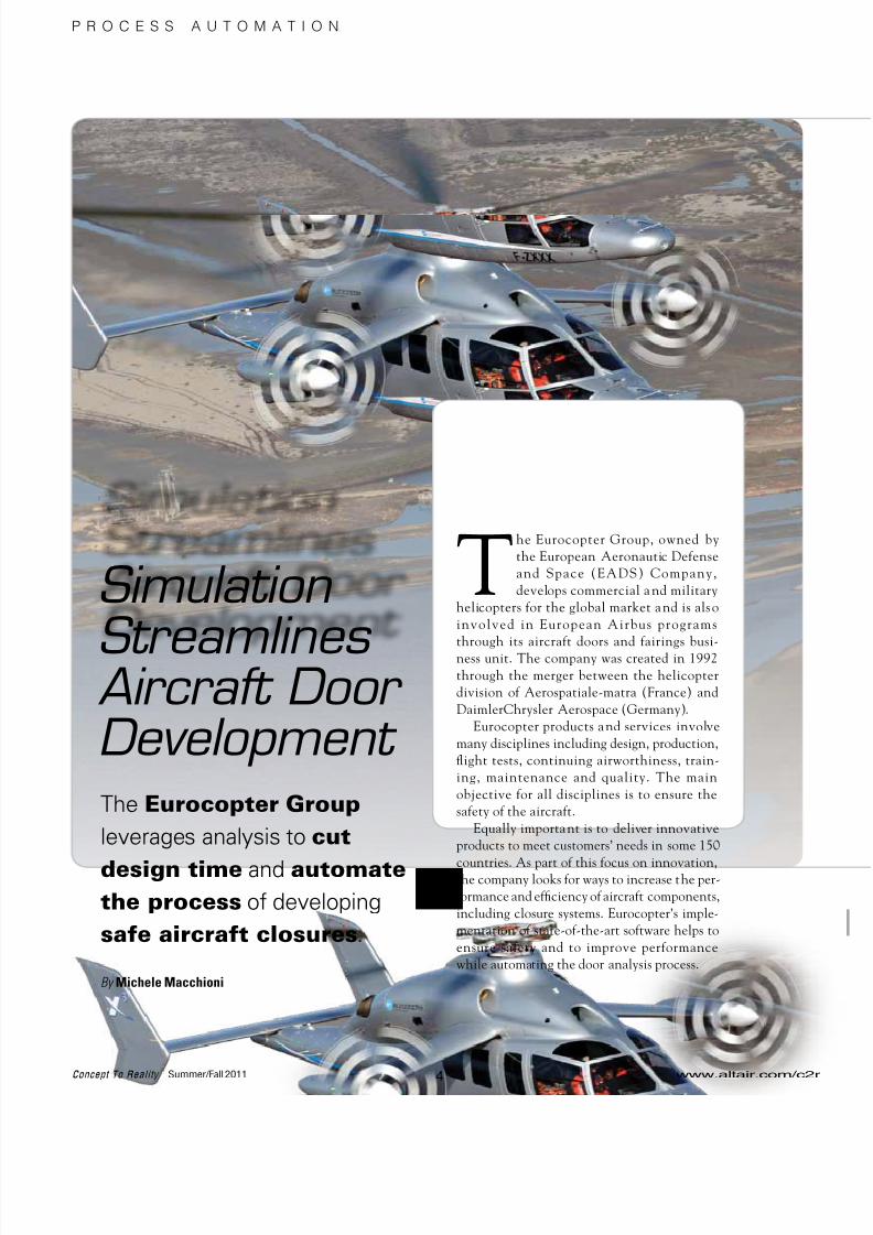
Simulation
StreamlinesAircraft DoorDevelopment
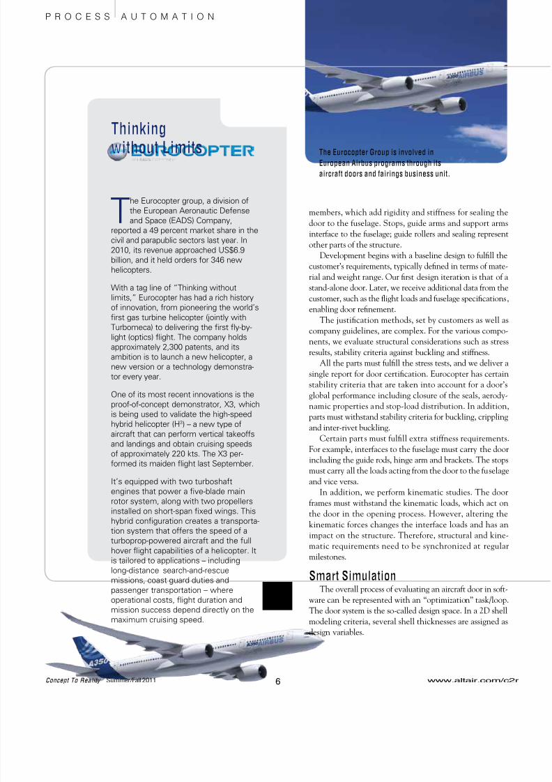
The Eurocopter Group, owned by
the European Aeronautic Defense
and Space (EADS) Company,
develops commercial a nd military
helicopters for the global market and is also
involved in European Airbus programs
through its aircraft doors and fairings busi-
ness unit. The company was created in 1992
through the merger between the helicopter
division of Aerospatiale-matra (France) and
DaimlerChrysler Aerospace (Germany).
Eurocopter products and services involve
many disciplines including design, production,
flight tests, continuing airworthiness, train-
ing, maintenance and quality. The main
objective for all disciplines is to ensure the
safety of the aircraft.
Equally important is to deliver innovative
products to meet customers’ needs in some 150
countries. As part of this focus on innovation,the company looks for ways to increase the per-
formance and efficiency of aircraft components,
including closure systems. Eurocopter’s imple-
mentation of state-of-the-art software helps to
ensure safety and to improve performance
while automating the door analysis process.
The Eurocopter Group
leverages analysis to cut
design time and automatethe process of developing
safe aircraft closures.
By Michele Macchioni

8/10/2019 C2R SummerFall 2011
http://slidepdf.com/reader/full/c2r-summerfall-2011 7/24
Door to DoorClosure systems are complex, with
many integrated parts. Whether theyare being developed for helicopters or
other aircraft, the doors must open, close and
work in emergency situations.
From product to product, we cannot start
with the same hypotheses. Door systems are
built according to each aircraft’s size and gov-
ernmental regulations.
The development process entails balancing
different requirements. The closure systems
must be robust in capabilities but light in
design. The design must fulfill customers’
requirements, even as these requirements
change. And, development must be completedon time to be in sync with client critical-path
program milestones.
In general, the company must meet
requirements for reliability, packaging,
weight, manufacturability and cost.Drilling down, engineers evaluate
structural and kinematic properties of the doors
with the objective of harmonizing the con-
straints and delivering doors that are designed
to operate for the service life of the aircraft and
safely in evacuation situations. Simulation tools
enable Eurocopter to virtually assess the perfor-
mance and robustness of designs through an
iterative design analysis process.
Stepping through DevelopmentWhen you think of an aircraft door, con-
sider its structural components as well asinterfaces to the fuselage. Structural compo-
nents include the door frame, beams and edge
Optimizing a Door Support Arm
In addition to stress engineers employing simulation tools,
Eurocopter’s engineering team includes optimization specialists
whose job it is to investigate innovative designs for aircraft doors
and components. A case in point is a recent door support arm
for the Fairchild Dornier 728 aircraft. Using Altair’s structural
optimization software, engineers achieved a weight reduction ofapproximately 20% in its design.
Altair OptiStruct topology optimization technology was used within the Eurocopter design
process. Engineers were able to create design concepts – taking into account performance
and product objectives – without having to develop, evaluate and iterate on multiple CAD
design proposals.
The initial door hinge design provided by OptiStruct maximized the stiffness for three load
cases: door blocking, emergency opening and damper hit. In addition, draw direction
constraints were included as part of the optimization, yielding a design tailored to the
specific method of manufacture. Secondary analyses further reduced the part mass by
optimizing the shapes and sizes of ribs for all load cases and a maximum allowable stress
level.
The results were impressive. Eurocopter reduced the door support arm weight by approxi-
mately 20% without compromising the stiffness of the part. In addition, the turnaround time
to develop and validate the new door support arm design was reduced from three months to
three weeks.
Also, Eurocopter has successfully applied optimization tools on other projects. For example,
engineers have simulated stop brackets and hinge arms as well as optimized the weight of
the entire door system on a regional jet.
www.altair.com/c2r Concept To Reality Summer/Fall 201
5
P R O C E S S A U T O M A T I O N
Simulation enables engi-
neers to analyze forces on
door components (above
left) and von Mises
stresses (above right).
Passenger door with
support arm
Initial Design
Eurocopter reduced
the door support arm
weight by ~ 20% and cut
design time by 75%.
Final Design
8/10/2019 C2R SummerFall 2011
http://slidepdf.com/reader/full/c2r-summerfall-2011 8/24

8/10/2019 C2R SummerFall 2011
http://slidepdf.com/reader/full/c2r-summerfall-2011 9/24
Reducing weight is the objective, and components must
be optimized by fulfilling all of the requirements. These are
formalized by means of constraints – such as stiffness and
stress – among the selected load cases. Manufacturing con-
straints, such as the maximum shell thickness or type of
material to be used, are also considered. This concept is
valid when referring to global calculations or to a single
component.
As part of the process, we develop three types of finite-
element models (FEMs). For example, the global FEM
represents the global structure, which is provided by the air-
plane manufacturer and is a coarse model. The intermediate
FEM is typically used to evaluate load cases; these models
are more refined. The detailed FEMs, for stress analysis, are
very refined and created for local investigations.
Depending on the component, we define the connec-
tions and the material; then, we decide which type of model
to run. Altair’s modeling and visualization simulation tools,
HyperMesh and HyperView, allow us to rapidly respond to
changes in design specifications and loads and make revi-
sions very quickly.Our previous pre- and post-processing solutions did not
enable us to process models as quickly. One of the primary
drivers to migrate to the Altair HyperWorks suite was to
keep on track in terms of our deadlines.
In making the move, we also discovered the customiza-
tion capabilities of the software. In the f ramework of
creating global models of the door system, for instance, we
leveraged HyperWorks’ scripting language to support the
automation of batch meshing and the model organization
process for specific analyses and solvers.
Being able to tailor HyperWorks for our workflow pro-
cesses and environment has resulted in several benefits. For
example, we have more control over parameters such as
material and rivets, for which we have constructed proprie-
tary databases. HyperWorks also provides a homogeneous
pre- and post-processing environment. Together, these have
contributed significantly to reducing our CAE cycle times.
The gains that we have made in the Stress Department
– in creating models to specific standards in weeks vs.
months – have been recognized by other engineering
departments within Eurocopter. In fact, an initiative is
under way to transfer these best practices to other parts of
the company as Eurocopter works toward harmonizing its
tools and processes.
Through the HyperWorks open-architecture and script-
ing language, Eurocopter has reduced development time by
automating repetitive tasks, even as designs have changed
late in the process. We have also established a framework to
build models to standards, thus helping to enable qualityassurance and reliability.
Michele Macchioni for Eurocopter Deutschland stress
engineering.
www.altair.com/c2r Concept To Reality Summer/Fall 201
7
P R O C E S S A U T O M A T I O N
For more information on HyperWorks,
visit www.altair.com/c2r.

8/10/2019 C2R SummerFall 2011
http://slidepdf.com/reader/full/c2r-summerfall-2011 10/24
Bird strikes have been occurring for more than a
century. In fact, Orville Wright was the first to
report a bird strike in 1905.
In the United States, the Federal Aviation
Administration (FAA) notes that bird strikes occur during
daylight hours, usually during a plane’s approach and land-
ing roll. Ninety-two percent of the strikes take place at orbelow 3,000 ft above ground level. Gulls, doves and pigeons
account for approximately one-third of the encounters.
According to USA Today, which analyzed FAA data,
severe collisions between airborne jetliners and birds have
soared over the past two years. In 2009, severe bird strikes
above 500 ft hit a high of 150; 2010 had a similar number of
bird strikes. Although the FAA is pushing airports to do a
better job of keeping birds away from runways, serious inci-
dents above 500 ft are taking place.
The FAA certifies civil aircraft to meet a series of mini
mum standards. Aircraft must be designed and built to fly
safely as well as survive situations in which internal o
external factors – such as bird strikes – may interfere with
safe operations. To address these regulatory requirements
many aircraft manufacturers are turning to simulation tech
nology in product development.
Making an ImpactRecent events have highlighted the dangers from bird
strikes in flight. The famous US Airways Hudson Rive
emergency landing was the result of two engine failure
from bird strikes (see photo above). At a minimum, bird
strikes cause damage to the airframe that adds repair costs
At the other end of the spectrum, they can cause cata
strophic damage potentially resulting in a crash and loss olife. Many airports are implementing changes to reduce bird
populations around their facilities to reduce incidents.
The airplane manufacturers still are required to con
duct bird strike tests and design structures that ca n
withstand a bird strike event. That is why a key goal in
product development is to deliver airframes and engine
that pass regulatory requirements on the first test. Failure
to do so results in redesign, refabrication, retesting – and
lost time, money and effort.
www.altair.com/c
8Concept To Reality Summer/Fall 2011
D E S I G N S T R A T E G I E S
Bird Strike SimulationTakes Flight
The increasing number
of bird-plane impacts gives
rise to new CAE methods
to address aircraft safety.
By Robert Yancey

8/10/2019 C2R SummerFall 2011
http://slidepdf.com/reader/full/c2r-summerfall-2011 11/24
Following the lead of the automotive
industry with virtual crash testing, many air-
plane manufacturers a nd suppliers areturning to virtual simulations of bird strike
events. Success here with explicit nonlinear
dynamic transient analysis codes such as
RADIOSS from Altair Engineering can dra-
matical ly reduce costs and improve
performance.
The Power of the ProcessBird strike analysis is far different than
automotive crash analysis. Various finite-
element methods have been used, but the
method that is becoming a standard in bird
strike analysis is the SPH method, based onsmooth particle hydrodynamics. This tech-
nique allows the kinetic energy of the bird
test article to be imparted to the structure
while allowing the bird to break apart and
disperse (see images to the right).
The analysis is set up to reproduce the
standard regulatory test method. Some air-
craft companies use gelatin to represent a bird
while others employ actual test articles. As the test arti-
cle impacts the structure, it disperses, much like a water
balloon hitting the ground.
The SPH computational method models the bird test arti-
cles with a set of “particles” (disordered points) that intersect
www.altair.com/c2r Concept To Reality Summer/Fall 201
9
D E S I G N S T R A T E G I E S
The underbelly fairing is an area of an airplane at risk
to bird strike events. As a secondary structure,
lightweight composite material constructions are
desired for underbelly fairings. Through a combination
of advanced structural optimization capabilities in
OptiStruct and the SPH computational methods in
RADIOSS, both developed by Altair Engineering, Inc.,
aircraft manufacturers have the ability to streamlinecomposite material designs taking into account bird
strike impacts.
To incorporate a bird strike event as a load case within a
composite optimization process, kinetic energy, velocity
and deceleration information, together with the
deformation limit desired, first need to be calculated to
estimate the static equivalent loads on the structure.
Using OptiStruct, an optimization analysis can then be
performed to determine the optimal shape, thickness
and order of each ply in the stack – taking into account
the static equivalent loads for the bird strike event
simultaneously with the fairing’s frequency targets and
static load cases.
Subsequently, one would need to consider the most
critical locations for a bird strike and then add reinforce-ment to those areas. For example, sections of the fairing
covering critical components – such as fuel tanks, flight
control electronics, etc. – would need to have adequate
reinforcement to withstand a bird strike event. A
potential approach would be to perform the worst-case
bird strike analysis, using RADIOSS, to determine a
minimum thickness in those areas to ensure flight
safety, then use this minimum thickness constraint in
those zones in the OptiStruct optimization run.
Optimizing Composite Underbelly Fairings for Bird Strike Events
The images above depict the use of the smooth particle hydrodynamics
(SPH) methods with RADIOSS software for bird strike analysis.
8/10/2019 C2R SummerFall 2011
http://slidepdf.com/reader/full/c2r-summerfall-2011 12/24
Initiatives to advance aviation technology are under
way at the National Institute for Aviation Research
(NIAR) at Wichita State University. Located in
Wichita, Kan., the “Air Capital of the World,” NIAR,
an Altair research partner, is the largest university
aviation Research & Development institution in theUnited States.
NIAR is able to integrate business, government and
academia in cooperative efforts to advance aviation
technology; a key example of this is NIAR’s Computa-
tional Mechanics Laboratory. This cutting-edge
laboratory provides research focused on the develop-
ment and application of numerical methods in the
areas of crashworthiness, structures, numerical
optimization techniques, virtual product development
and certification.
According to the Computational Mechanics Technical
Director Dr. Gerardo Olivares, the lab is currentlycollaborating with an aerospace industry advisory group
and researchers at NASA Glenn to develop and validate
numerical modeling techniques to simulate bird impacts
on aircraft structures. Additionally, current ongoing
research includes a joint sponsored project by the
Federal Aviation Administration, aerospace companies
and seat suppliers on Certification by Analysis
of Aircraft Seat Structures. The objective of
this project is to develop numerical modeling
techniques to
support the dynamic
certification process
of aircraft seat
structures per
Advisory Circular20-146.
The aerospace industry is conservative by nature, and
Dr. Olivares notes that pressure to reduce development
costs and cycles is driving companies to introduce
advance simulation tools in the design, development
and certification process. However, since many current
engineers have not been exposed to the technology,
there is a lack of qualified staff trained to apply the use
of advanced analysis tools.
The Computational Mechanics Lab at NIAR plays a key
role in solving this problem. It hires 12 to 16 graduate
students, training them to use a combination ofadvanced simulation tools, analytical skills and experi-
mental methods, all of which are critical in the aircraft
design process. “From the lab, we expect the students
to move into industry where they can either create or
join existing advanced simulation groups and transfer
the technology,” says Dr. Olivares.
with each other through external
forces rather than connections to
nodes. As such, the results areinsensitive to the deformation of
the birds – but provide a clear
understanding of the strike impact
on the structure.
The SPH method is well-suited
to hydrodynamic material (and the
bird material law is mainly hydro-
dynamic). It’s based on interpolation
theory and allows any function to
be expressed in terms of its values at
a set of particles. In addition, it per-
mits the motion of a discrete
number of particles to be followedin time.
In the actual simulation process, the target structure i
modeled from CAD data as a finite-element model. Th
most important features are connection characteristics (rivets) and material behavior (plasticity, rupturing).
The RADIOSS bird strike simulation process include
rupture checks and estimates on the bird’s residual energy in
case of penetration, number of broken rivets, and behavio
of the rupture zone to predict the risk of debris separating
from the structure and possibly impacting another part o
the aircraft. An additional consideration is the ability of the
vehicle to fly after impact despite damage inflicted (change
in aerodynamic characteristics due to deformation).
Though one single simulation is not very CPU-intensive
many simulations are required to assess the sensitivity of the
structure, the number of possible impacts on various zone
of the structure a nd the dispersion of impact typ(incidence). Therefore, optimization and sensitivity analysi
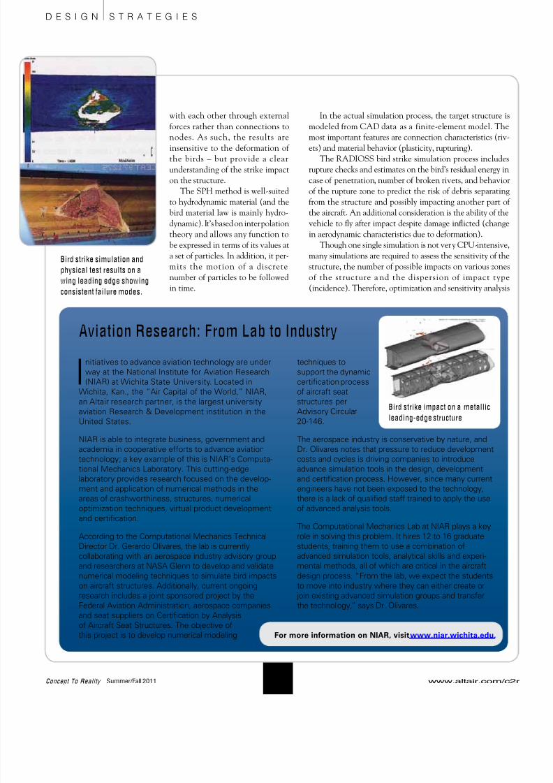
Aviation Research: From Lab to Industry
For more information on NIAR, visit www.niar.wichita.edu.
Bird strike impact on a metallic
leading-edge structure
www.altair.com/c
10Concept To Reality Summer/Fall 2011
D E S I G N S T R A T E G I E S
Bird strike simulation and
physical test results on awing leading edge showing
consistent failure modes.
8/10/2019 C2R SummerFall 2011
http://slidepdf.com/reader/full/c2r-summerfall-2011 13/24
software may be useful to limit the number of simulations
that need to be car ried out and to properly assess the
phenomenon involved in such events.Typically, aircraft manufacturers build physical rigs to
carry out physical testing. They marry the results of the phys-
ical and simulation testing to improve product development.
Through rigorous physical and virtual testing correlation
efforts, the bird strike test articles deliver the right kinetic
energy to the structure, which is important in this type of
simulation. Altair provides certification correlation test
results for virtual bird models of various types and sizes that
can be run with RADIOSS. These results have been corre-
lated with impacts on wings, nacelles and engines.
The Simulation DifferenceIn summary, many aircraft OEMs and suppliers have
improved their bird strike analysis process on several fronts
by using virtual simulation. Altair has been a partner with
many of these companies, providing the technology and
expertise to make these efforts successful. The cost of per-
forming simulations is considerably less than conducting
multiple physical tests. Additionally, a greater number ofsituations can be analyzed and the effects of design changes
can be evaluated very quickly, allowing for the optimization
of components for weight.
What’s more, simulation tools have saved time in the
process. Simulation provides confidence in the design so
that physical testing can run in parallel with production
with a high level of success. The goal is getting the design
right the first time – and simulation has proven in many
applications to provide the right answers before any physical
evaluations are attempted.
Robert Yancey is Executive Director, Global Aerospace, Altair
Engineering, Inc, Troy, Mich.
For more information about RADIOSS and
bird strike analysis, visit www.altair.com/c2r.
www.altair.com/c2r Concept To Reality Summer/Fall 201
11
Acoustics, Noise Vibration and HarshnessCoustyxCoustyx is an analysis software for simulating acoustic phenomena and optimizing
NVH performance.
For more information, contact:
Advanced Numerical Solutions, LLC
3956 Brown Park Drive Suite B
Hilliard OH 43026
www.coustyx.com
Benefits:
• Allows very large models (1 million DOFs);
• Parallel implementation on shared memory, multi-core processors to
yield faster solutions; and
• Most comprehensive selection of Boundary Condition options, and
built-in acoustic wave sources.
“Coustyx is the most advanced Boundary Element (BE) software package
on the market today. Not only does it incorporate the Fast Multipole Method
(FMM) in its solver, it uses iterative techniques to quickly converge to the
solution, instead of solving the problem directly.“Unlike other BE software packages, Coustyx has thought of all the details.
No more fighting the program to try and export your data in a user-friendly
format. No more endless stipulations to incorporate the FMM solver into
your model. And best of all, no more wading through the useless help file, or
wondering if the technical support crew will be getting back with you. Coustyx
is simply the best out there.”
Daniel Tengelsen, Researcher,
Brigham Young University
D E S I G N S T R A T E G I E S
A D V E R T I S E M E N T
8/10/2019 C2R SummerFall 2011
http://slidepdf.com/reader/full/c2r-summerfall-2011 14/24www.altair.com/c
12Concept To Reality Summer/Fall 2011
T H E A R T O F I N N O V A T I O N
Alliant Techsystems Inc. (ATK)
Aerospace Systems, headquartered
in Magna, Utah, U.S.A., produces
solid rocket propulsion systems
and is a leading supplier of military and com-
mercial aircraft structures. It also has extensive
experience supporting human and space pay-
load missions.
That experience came into play on a
recent project for the National Aeronauticsand Space Administration’s (NASA) Orion
Multi-Purpose Crew Vehicle (MPCV).
ATK served as the subcontractor responsi-
ble for the Launch Abort Motor, designed
to lift the space crew module off the pri-
mary launch vehicle in an emergency
on the launch pad and during
launch up to 300,000 ft of flight.
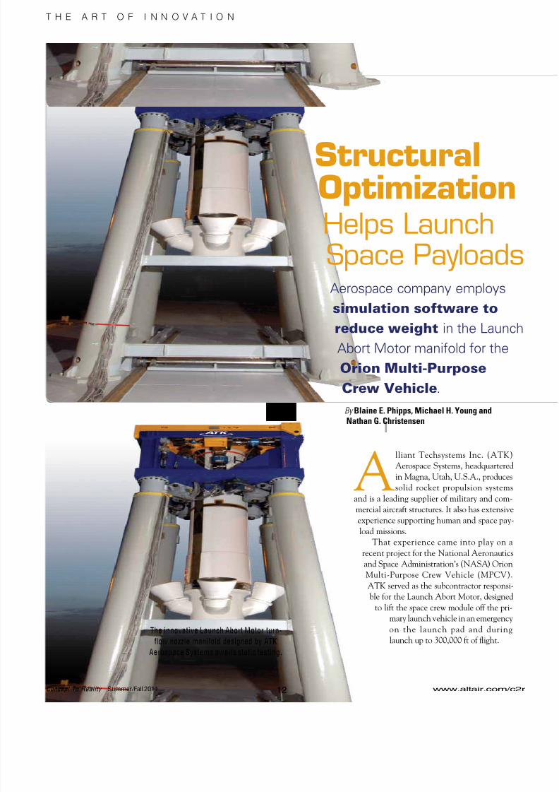
StructuralOptimizationHelps LaunchSpace PayloadsAerospace company employs
simulation software to
reduce weight in the Launc
Abort Motor manifold for the
Orion Multi-Purpose
Crew Vehicle.
By Blaine E. Phipps, Michael H. Young andNathan G. Christensen
The innovative Launch Abort Motor turn-
flow nozzle manifold designed by ATK
Aerospace Systems awaits static testing.

8/10/2019 C2R SummerFall 2011
http://slidepdf.com/reader/full/c2r-summerfall-2011 15/24www.altair.com/c2r Concept To Reality Summer/Fall 201
13
T H E A R T O F I N N O V A T I O N
ATK conducts a ground test of the Launch
Abort Motor at its facility in Utah.
The optimized titanium manifold (left) weighs
approximately 1,000 lbs versus the steel version
(right), which weighs around 2,000 lbs.
The manifold is designed so that combustion
thrust gases create a pulling force on the crew
module to lift it out of harm’s way.
The Launch Abort Motor – 17 ft long, 3 ft in diameter
and capable of generating a half-million pounds of thrust –
was designed to include composite motor case turn-flownozzle manifold technology to reduce overall launch system
weight, critical to space missions, while ensuring crew
safety. Unlike conventional rocket motors, the innovative
exhaust turn-flow manifold is positioned at the forward end
of the motor – so that the combustion thrust gases are com-
pressed evenly through four nozzle ports angled away from
the crew capsule (aft) end, creating a forward-thrust reac-
tion (pulling force) on the crew module.
The initial design, steel manifold, weighed slightly less
than 2,000 lbs and supported an early concept flight test
(see YouTube “Pad Abort 1”). However, to meet the weight
target of 1,300 lbs or less, ATK and Lockheed Martin Space
Systems Company agreed to change the manifold materialto a high fracture toughness titanium for the much lower
weight, flight weight nozzle manifolds. Using specialized
optimization techniques, ATK further reduced the mani-
fold weight by 300 lbs while meeting a ll strengt h
requirements and deflection limits.
Lighter is BetterWhen launching payloads into space, every pound saved
matters. So when the project allocated new mass require-
ments to hit per formance requirements, further weight
reduction throughout the launch abort system was needed.
Although already within the weight budget, to support the
program, ATK stepped up to further reduce weight on the
Launch Abort Motor nozzle manifold using structural opti-
mization on the entire manifold.
ATK engineers pursued a two-phased simulation strat-
egy. This approach applied operational pressures and line
loads to both computer simulations and to a physical test
specimen in a specially designed test fixture. The test speci-
men validated computer simulations of motor operation in a
complex flight loading environment.
ATK had a team of ballistics, structural, fluids and
thermal engineers working on this complex project. The
optimization problem was set up in the following manner.
First, engineers identified the design variables and designspace, which also included external surfaces of the mani-
fold body.
Next, the responses of what could be measured were
established. The mass and the von Mises stress in the mani-
fold also needed to be considered.
The final objective was to minimize the manifold mass
using a simulation-driven design methodology for the
given constraints’ performance target.
8/10/2019 C2R SummerFall 2011
http://slidepdf.com/reader/full/c2r-summerfall-2011 16/24
Alliant Techsystems Inc. (ATK) is a Fortune 500
aerospace, defense, security and sporting
company with more than 18,000 employees and
operations in 24 states, Puerto Rico and internationally. It
was launched as an independent company in 1990 when
Honeywell spun off its defense businesses to sharehold-
ers. ATK Aerospace Systems, ATK Armament Systems,
ATK Missile Products, and ATK Security and Sporting
comprise the business lines.
ATK expanded into the aerospace market with the
acquisition of Hercules Aerospace Company in 1995 and
Thiokol Propulsion in 2001, which transformed the
company into the largest supplier of solid propellant
rocket motors and a provider of high-performance
composite structures.
ATK Aerospace Systems products and services include
solid propulsion systems and rocket motors; advanced
composite structures and components; and satellite
structures, components and systems. In addition, this
business structure provides advanced antennae and
radomes for weapons and ships, energetic materials,
military flares and decoys, and space engineeringservices.
As part of ATK Aerospace Systems, ATK Space Launch
Systems is focused on NASA’s human spaceflight
programs. Space Launch products include the Space
Shuttle’s Reusable Solid Rocket Motor, the abort motor
for NASA’s Orion MPCV Launch Abort System, the
Booster Separation Motors and Booster Deceleration
Motors for the Space Shuttle and Liberty Launch Vehicle.
FocusedForward
www.altair.com/c
14Concept To Reality Summer/Fall 2011
T H E A R T O F I N N O V A T I O N
Getting Off the GroundOptimization of the flight weight nozzle manifold
offered its own set of challenges considering thatalong with the approximate 60% weight density reduc
tion, the modulus of elasticity is also reduced abou
60% compared to steel. This complicates many struc
tural issues in the nozzle manifold such as strain
deflection limits and joint rotations at critical sea
interfaces. Switching from titanium to steel is not sim
ply trading out the materials!
The optimization model started with the baseline
steel manifold working towards an optimized fligh
weight manifold using titanium mechanical properties
Next, engineers “smoothed” all external surfaces of the
steel manifold configuration, making uniform thick
ness thrust ports. These actions reduced the weight othe steel manifold from approximately 2,000 lbs to
1,300 lbs on the titanium design.
ATK engineers then analyzed the performance o
the manifold/nozzle assembly taking into consideration
operational pressures based on computational fluid
dynamics (CFD) results and axial line loads. Later, vir
tual simulations on t he manifold/hydroproof tes
fixture were performed to determine a proof test pres
sure that would envelope the stress response in the
manifold for operational conditions.
Since the proof test is the most severe loading envi
ronment, the manifold was optimized to the proof tes
loads and configurations.
The Outer LimitsBecause requirements dictated that the manifold’
inner-profile remain u nchanged, the only way to
reduce weight was to remove material from the outside
profile. The topological optimization methodologie
employed in Altair Engineering, Inc.’s OptiStruct were
chosen for the task.
OptiStruct’s free-shape optimization capabilitie
enabled engineers to treat every node on the outer surface
of the manifold’s finite-element model (FEM) as an indi
vidual design var iable. OptiStruct then automaticallygenerated shape design variables for each surface node so
that each node could move inward or outward as needed
Stress and displacement constraints were prescribed
for the manifold weight optimization, and the operationa
pressure loading was applied. As the optimization pro
ceeded, the outer profile of the manifold started to thin
where it could without violating the stress, strain or dis
placement constraints.

8/10/2019 C2R SummerFall 2011
http://slidepdf.com/reader/full/c2r-summerfall-2011 17/24www.altair.com/c2r Concept To Reality Summer/Fall 201
15
T H E A R T O F I N N O V A T I O N
ATK also employed simulation
to determine proof test pressure
loads to validate the manifold for
predicted operational loads.
As part of the iterative process, the configuration of the
nodes changed during the thinning process, requiring
engineers to remesh some of the manifold’s components.
The nozzle ports, for example, were slightly out of round as
a result of the port geometry and the distribution of the
pressure loads. It was critical to keep the nozzle stiff so it
wouldn’t deflect too far when under nozzle thrust loads and
adversely affect the motor’s performance. In addition, the
integrity of the seals between the primary and secondary
O-ring joints needed to be verified; the software predicted
O-ring gaps between both interfaces.The operational analysis determined a stress value for
the motor. Because those stresses were well under stress
threshold levels, the optimization cycle was repeated until
the manifold reached optimum weight.
Proof TestThe second part of the two-phased strategy involved
optimizing the mani fold to the proof test loads
and configurations. For the titanium manifold proof test
configuration, mounting the manifold onto a composite
pressure vessel was simulated and a thrust relief piston
attached to each of the nozzle ports. Fluid was pumped into
the system to simulate the operational pressures.
During an operational flight, there is a variable internal
pressure dist ribution within the manifold. To simulate
actual flight conditions in the proof test, the thrust relief
piston was designed to move down, reacting thrust loads at
each of the nozzle port locations to simulate axial thrust
and pressure loads.A FEM of this test proof configuration was used in the
optimization process. A study was performed to determine
what proof pressure was required in the proof test configu-
ration to match operational stresses.
Engineering requirements for the test simulation were
constant pressure inside the manifold and axial and sym-
metric boundary conditions, including an axial thrust load
over 500,000 lbf.
8/10/2019 C2R SummerFall 2011
http://slidepdf.com/reader/full/c2r-summerfall-2011 18/24
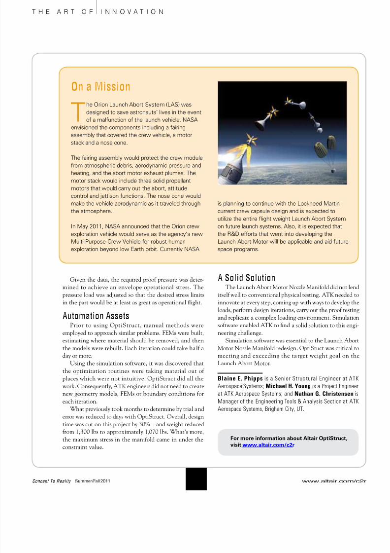
On a Mission
The Orion Launch Abort System (LAS) was
designed to save astronauts’ lives in the event
of a malfunction of the launch vehicle. NASA
envisioned the components including a fairing
assembly that covered the crew vehicle, a motor
stack and a nose cone.
The fairing assembly would protect the crew module
from atmospheric debris, aerodynamic pressure and
heating, and the abort motor exhaust plumes. The
motor stack would include three solid propellant
motors that would carry out the abort, attitude
control and jettison functions. The nose cone would
make the vehicle aerodynamic as it traveled through
the atmosphere.
In May 2011, NASA announced that the Orion crew
exploration vehicle would serve as the agency’s new
Multi-Purpose Crew Vehicle for robust human
exploration beyond low Earth orbit. Currently NASA
is planning to continue with the Lockheed Martin
current crew capsule design and is expected to
utilize the entire flight weight Launch Abort System
on future launch systems. Also, it is expected that
the R&D efforts that went into developing the
Launch Abort Motor will be applicable and aid future
space programs.
www.altair.com/c
16Concept To Reality Summer/Fall 2011
T H E A R T O F I N N O V A T I O N
Given the data, the required proof pressure was deter-
mined to achieve an envelope operational stress. The
pressure load was adjusted so that the desired stress limits
in the part would be at least as great as operational flight.
Automation AssetsPrior to using OptiStruct, manual methods were
employed to approach similar problems. FEMs were built,
estimating where material should be removed, and then
the models were rebuilt. Each iteration could take half a
day or more.
Using the simulation software, it was discovered that
the optimization routines were taking material out of
places which were not intuitive. OptiStruct did all the
work. Consequently, ATK engineers did not need to createnew geometry models, FEMs or boundary conditions for
each iteration.
What previously took months to determine by trial and
error was reduced to days with OptiStruct. Overall, design
time was cut on this project by 30% – and weight reduced
from 1,300 lbs to approximately 1,070 lbs. What’s more,
the maximum stress in the manifold came in under the
constraint value.
A Solid SolutionThe Launch Abort Motor Nozzle Manifold did not lend
itself well to conventional physical testing. ATK needed to
innovate at every step, coming up with ways to develop the
loads, perform design iterations, carry out the proof testing
and replicate a complex loading environment. Simulation
software enabled ATK to find a solid solution to this engi
neering challenge.
Simulation software was essential to the Launch Abor
Motor Nozzle Manifold redesign. OptiStuct was critical to
meeting and exceeding the ta rget weight goal on th
Launch Abort Motor.
Blaine E. Phipps is a Senior Struc tural Engineer at ATK
Aerospace Systems; Michael H. Young is a Project Engineeat ATK Aerospace Systems; and Nathan G. Christensen i
Manager of the Engineering Tools & Analysis Section at AT
Aerospace Systems, Brigham City, UT.
For more information about Altair OptiStruct,
visit www.altair.com/c2r
8/10/2019 C2R SummerFall 2011
http://slidepdf.com/reader/full/c2r-summerfall-2011 19/24
P h o t o c o u r t e s y o f N A S A A m e s R e s e a r c h C e n t e r
www.altair.com/c2r Concept To Reality Summer/Fall 201
17
T R E N D S I N T E C H N O L O G Y
In the past, scientific and engineering advancements
relied primarily on theoretical studies and physical
experiments. Today, however, computational model-
ing and simulation are equally valuable in such
endeavors, especially for an agency such as the National
Aeronautics and Space Administration (NASA). With amission “to pioneer the future in space exploration, scien-
tific discovery and aeronautics resea rch,” the use of
high-end computing (HEC) for high-fidelity modeling and
simulation has become integral to all four of NASA’s mis-
sion directorates: aeronautics re search, exploration
systems, science and space operations.
These HEC resources are provided at NASA’s Advanced
Supercomputing (NAS) Division at Ames Research Center,
Moffett Field, Calif . NAS offers production a nd
development systems to U.S. scientists in government,
industry and at universities, with users currently numbering
over 1,500. Projects such as designing safe and efficient
space exploration vehicles, projecting the impact of human
activity on weather patterns and simulating space shuttle
launches are studied using the facility’s supercomputers.“We provide world-class HEC and associated services to
enable NASA scientists and engineers in all mission direc-
torates to broadly and productively employ large-scale
modeling, simulation and analysis for mission impact. We
pursue a future where these services empower ever greater
NASA mission successes,” says William Thigpen, the HEC
capability deputy project manager at the NAS Division.
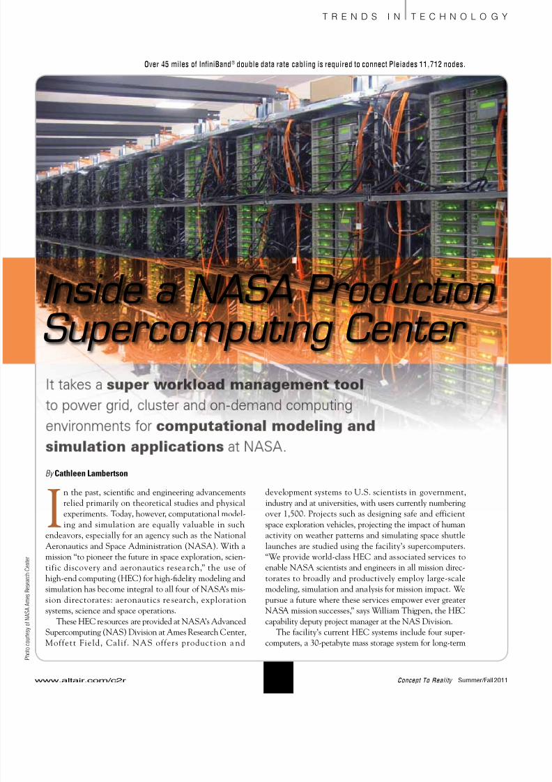
The facility’s current HEC systems include four super-
computers, a 30-petabyte mass storage system for long-term
By Cathleen Lambertson
Inside a NASA ProductionSupercomputing Center
Over 45 miles of InfiniBand® double data rate cabling is required to connect Pleiades 11,712 nodes.
8/10/2019 C2R SummerFall 2011
http://slidepdf.com/reader/full/c2r-summerfall-2011 20/24
data storage, two secure front-end systems requiring two-
factor authentication and two secure unattended proxy
systems for remote operations. Key system resources at NASinclude: Pleiades, a 111,872-core, 1.315 petaFLOPS (Pflop/s)
SGI® Altix® ICE cluster; Columbia, a 4,608-processor SGI
Altix® (Itanium 2); Schirra, a 640-processor IBM® Power5+;
and hyperwall-2, a 1,024-core, 128-node GPU cluster.
Since 300 to 400 jobs are typically running 24 hours a
day, seven days a week, the NAS staff works nonstop to
meet the demands for time on these machines. “Our mis-
sion is to accelerate and enhance NASA’s mission of
space exploration, scientific discovery and aeronautics
research by continually creating and ensuring optimal
use of the most productive HEC environment in the
world,” says Thigpen. “Our viewpoint is that we spend a
lot of money getting hardware in here, but it really makessense that it is effectively exploited by our users because
the bottom line is we’re not about big hardware, we’re
about big science and engineering.”
Building a Supercomputer – PleiadesOriginally installed in the fall of 2008, the Pleiades
supercomputer is an SGI Altix ICE 8200/8400 InfiniBand®
cluster with Intel® Xeon® quad and hex-core processors, run-
ning at 1.09 Pflop/s on the LINPACK benchmark – the
industry standard for measuring a system’s floating-point
computing power. Considered one of the most powerful
general-purpose supercomputers ever built, each of the
Pleiades 184 racks (11,712 nodes) has 16 InfiniBand switches
to provide the 11D dual-plane hypercube that provides the
interconnect for the cluster. The InfiniBand fabric intercon-
necting Pleiades’ 11,712 nodes requires more than 45 miles
of cabling. Pleiades is the largest (measured by number of
nodes) InfiniBand cluster in the world (see sidebar for full
system specifications).
Currently ranked seventh on the TOP500 list of the
world’s most powerful computers, the Pleiades supercom-
puter was built to augment NASA’s current and future
high-end computing requirements. “Pleiades is a general-
purpose machine and provides for all three components of
supercomputers – [capability, capacity and time critical],”says Thigpen. “We have users running jobs using over
18,000 cores, providing new insights into the formation of
the universe. There are numerous users running parameter
studies (often thousands) using from one to a few thousand
cores. Pleiades is also being utilized to answer time-critical
questions concerning the shuttle.”
The most recent upgrade to Pleiades occurred in May
2010 and included the incorporation of 32 SGI ICE 8400
racks with the Intel Xeon X5670 (Westmere) processor,
which effectively doubled the science and engineering com
pute capability to the NAS facility’s general user community
“Placing these racks into service involves the connection oover 4,400 cables. While 1,024 were done in the factory, the
rest had to be done on our floor,” notes Thigpen. “We then
performed an extensive series of tests at first focused on the
new racks and then on the total system. There are no other
systems with this many nodes connected via InfiniBand in
the world, and so we encounter and resolve issues tha
haven’t been seen elsewhere.”
According to Alan Powers, the HEC technical directo
for Computer Science Corp. at NAS, the goal of the upgrade
was to have an up-and-running production machine afte
the integration. “If you look at most other supercomputing
sites, it is hard for them to do this type of integration in thei
environment. We cut in these racks in two weeks, and nowthey are in production. We added 32 racks, which is consid
ered a very large machine to begin with at most sites, but we
just think of it as part of our system.”
Choosing Components and SoftwarePleiades was built to meet as many of the emerging NASA
science and engineering mission requirements as possible
while remaining within the HEC budget. “The Pleiade
architecture was chosen because it provided the best perfor
mance/cost ratio of the systems we looked at. Since its origina
installation in 2008, it has undergone two expansions. We
will continue to build it out as long as the fundamental eco-
nomics of the system remain sound, and the science and
engineering returns remain high,” states Thigpen.
To build Pleiades, NAS engineers began w ith the
components recommended by the vendor and those being
used on other systems. The result has been an easy
transition to the new environment for NASA users. “We
want an environment where the components complemen
each other, are an easy natural transition for our users and
provide a reliable environment,” says Thigpen. For example
the SGI ICE 8200 and 8400 are standard products that have
been taken to an extreme size at the NAS facility
Additionally, the InfiniBand network was expanded to
incorporate both the data analysis and visualization clusteras well as the storage system.
Another consideration is outlining and selecting a scal
able architecture. Powers explains, “We chose SGI because
it had a certain architecture that allowed us to build and
grow it. [It also had] the best price/performance based on ou
workload. Where we are today, we’re near a petaflop capabil
ity, and it’s been built over a couple of years; we’ve been
adding to it slowly. The other vendors’ price/performance
wasn’t even close to this platform.”
www.altair.com/c
18Concept To Reality Summer/Fall 2011
T R E N D S I N T E C H N O L O G Y

8/10/2019 C2R SummerFall 2011
http://slidepdf.com/reader/full/c2r-summerfall-2011 21/24
P h o t o c o u r t e s y o f N A S A E x p l o r a t i o n S y s t e m s M i s s i o n
D i r e c t o r a t e ,
P r i n c i p a l I n v e s t i g a t o r , J o s e p h O l e j n i c z
a k
www.altair.com/c2r Concept To Reality Summer/Fall 201
19
T R E N D S I N T E C H N O L O G Y
• 184 racks (11,712 nodes)
• 1.315 Pflop/s peak cluster
• 1.09 Pflop/s LINPACK rating (June 2011)
• Total cores: 111,872
• Total memory: 185 TB
• Nodes
5,888 Harpertown nodes
2 quad-core processors per node
Xeon E5472 (Harpertown) processors
Processor speed – 3 GHz Cache – 6 MB per pair of cores
Memory Type - DDR2 FB-DIMMs
1 GB per core, 8 GB per node
1,280 Nehalem nodes
2 quad-core processors per node
Xeon X5570 (Nehalem) processors
Processor speed - 2.93 GHz
Cache – 8 MB Intel® Smart Cache for 4
cores
Memory Type - DDR3 FB-DIMMs
3 GB per core, 24 GB per node
4,480 Westmere nodes
2 six-core processors per node
Xeon X5670 (Westmere) processors
Processor speed - 2.93GHz
Cache – 12 MB Intel® Smart Cache for 6
cores
Memory Type - DDR3 FB-DIMMs
2 GB per core, 24 GB per node
Subsystems
• 14 front-end nodes
• 1 PBS server
Interconnects
• Internode - InfiniBand, with all nodes connected in
a partial 11D hypercube topology
• Two independent InfiniBand fabrics
• InfiniBand DDR, QDR
• Gigabit Ethernet management network
Storage
• SGI® InfiniteStorage NEXIS 9000 home filesystem
• 12 DDN RAIDs, 6.9 PB total
• 7 Oracle Lustre cluster-wide filesystems
Operating Environment
• Operating system - SUSE® Linux®
• Job Scheduler – PBS Professional®
• Compilers - Intel and GNU C, C++ and Fortran
• MPI: SGI MPT, MVAPICH2, Intel MPI
Computational fluid dynamics (CFD) calculation of the flow
around the Orion crew module, with wind tunnel sting.
The Pleiades – System
Specifics
Managing the WorkloadWhen providing supercomputing resources to 1,500
users, 24/7, workload mana gement is a top priority.
Originally developed at NAS in the 1990s and then com-
mercialized, PBS Professional® workload management
software has been used since its inception. Commercially
developed by Altair Engineering, Inc., Troy, Mich., the
PBS platform is designed to power grid, cluster and on-
demand computing environments. PBS Professional is
used to manage all HEC resources at NAS, including
Pleiades. “We have found Altair continues to be receptiveto enhancements that NAS needs to manage unique sys-
tems. The choice for Pleiades was a natural progression
from years of a very effective working relationship with
Altair,” states Thigpen.
PBS Professional is a resource allocation tool that makes
it possible to create intelligent policies to manage distrib-
uted, mixed-vendor computing assets as a single, unified
system. Based on a policy-driven architecture, it continually
optimizes how technical HEC resources are used, ensuring
8/10/2019 C2R SummerFall 2011
http://slidepdf.com/reader/full/c2r-summerfall-2011 22/24www.altair.com/c
20Concept To Reality Summer/Fall 2011
T R E N D S I N T E C H N O L O G Y
that they are used effec-
tively and efficiently. Simply
put, the software looks at the
jobs that want to run, looks at the
resources available for them to run on and
makes the best match based on a number of
criteria. “Those criteria can include the user that’s
running and how many jobs that user currently has run-
ning, or how many cores his job is currently using. It canalso be the queue that a user submits their job in, and those
queues can have things limiting them, like how many jobs
are running or how many cores all of the jobs together are
using. It also can be the mission directorate those users are
in,” explains Thigpen.
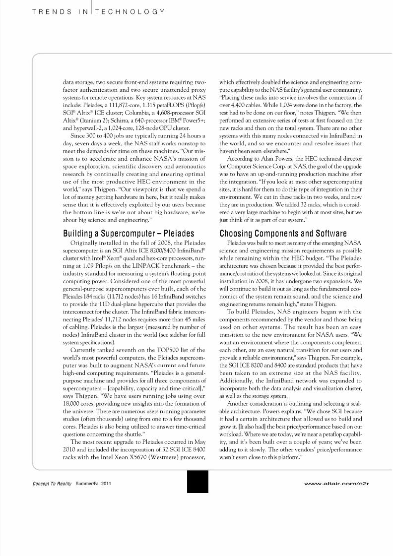
Powers adds: “The ‘P’ in PBS stands for ‘portable,’ and it
allows us to run this on any architecture. We’ve had PBS on
fat node architectures, on thin node clients and on IBM
architectures. PBS has been able to adapt to all those
c o m p u t i n g
envi ronments
This has allowed ou
users to have a consisten
set of batch scripts across these
different environments. They only
have to learn one thing. So one, it’
flexible; two, we can use it on any architec
ture; and three, it’s easy for users to learn.”
Your Own HEC EnvironmentAccording to Thigpen, HEC is an enabling technology
that allows a company to build products that can meet thei
customers’ requirements in a cost-effective manner: “By
spending a relatively small amount on a system, they can
run through hundreds or thousands of alternatives before
building a physical prototype. This will allow for a bette
product with lower production costs.”
However, there are many issues to address when consider
ing whether an HEC environment is the right choice for an
enterprise. “There has to be a balance between the cost of the
resources, the technology they enable, the increased produc
tivity of their staff, the potential return on their investmenand what their competition is doing,” Thigpen concludes.
Cathleen Lambertson is Contributing Editor, Tech Brief
Media Group.
The Pleiades
supercomputer
at the NASA
Advanced
Supercomputing
(NAS) facility
at NASA Ames
Research Center.
For more information on PBS Professional,
visit www.altair.com/c2r

8/10/2019 C2R SummerFall 2011
http://slidepdf.com/reader/full/c2r-summerfall-2011 23/24

8/10/2019 C2R SummerFall 2011
http://slidepdf.com/reader/full/c2r-summerfall-2011 24/24
Solver PowerIntroducing a new advanced CFD solver
and expanded linear and non-linear solutions
Collaborative Simulation ManagemenCollaboration tools making simulation
management natural and intuitive
Desktop IntegrationCAE pre- & post-processing within one
integrated desktop framework
Creating the Broadest
Open-Architecture CAE Solution
HyperWorks 11.0 demonstrates its commitment to
delivering the broadest CAE solution to the PLM market
by adding new products and a rich set of functionality
to the strong foundation of past releases.
Our goal at Altair has always been to provide the best
technology at the highest value to our customers, and the
HyperWorks 11.0 release is no exception.
Learn more about HyperWorks 11.0 at
www.altairhyperworks.com/hw11
1300 East 9th Street
Cleveland, Ohio 44114
Change Service Requested
PRSRT S
U.S. POST
PAIDST CLOUD
PERMIT#