c30-7 locomotive pack general electric...
TRANSCRIPT

C30-7 LOCOMOTIVE PACK
©2017 Virtual Rail Creations, in conjunction with Dovetail Games, LLC
Pag
e1
GENERAL ELECTRIC TRANSPORTATION SYSTEMS
C30-7 USER MANUAL FOR TRAIN SIMULATOR 2017

C30-7 LOCOMOTIVE PACK
©2017 Virtual Rail Creations, in conjunction with Dovetail Games, LLC
Pag
e2
CONTENTS
GENERAL DATA 3
OPERATING CONTROLS 5
EXTERIOR 5
MASTER CONTROLLER 7
BRAKESTAND 10
HEAD OF TRAIN DEVICE 12
ENGINE CONTROL PANEL 13
ENGINE CONTROL PANEL 2 17
ENGINE START COMPARTMENT 19
MISCELLANEOUS CONTROLS 20
OPERATIONS 21
PRE-ENGINE STARTUP 21
STARTING THE ENGINE 21
PRE-OPERATION EOT SETUP 23
PRE-OPERATION HTD SETUP 26
CONTROL NOTES 27
THE C30-7 FOR TRAIN SIMULATOR 29
SCENARIO CHEAT SHEETS 31
APPENDIX I: CREATING FAULTS IN SCENARIOS 33

C30-7 LOCOMOTIVE PACK
©2017 Virtual Rail Creations, in conjunction with Dovetail Games, LLC
Pag
e3
GENERAL DATA
Model C30-7 Horsepower 3000 Type (AAR Symbol) C – C Engine GE-FDL16 MAJOR DIMENSIONS Length 67 ft-3 in. Width 10 ft-3-1/4 in. Height 16 ft. Length Between Bolster Centers 40 ft-11 in. Truck Wheel Base 13 ft-7 in. MINIMUM CURVE Locomotive Alone 273’ or 21 degrees Coupled to Train 273’ or 21 degrees DRIVE Traction Motors Six GE-752 Wheel Diameter 40 in. WEIGHT Minimum 366,000 lbs. Maximum 420,000 lbs. SUPPLIES Fuel Min/Max 3250/4000 gal. Cooling Water 365 gal. Lubricating Oil 380 gal. Governor Oil 2 qt. Sand 60 cu. ft.

C30-7 LOCOMOTIVE PACK
©2017 Virtual Rail Creations, in conjunction with Dovetail Games, LLC
Pag
e4
Model C30-7 Dates Manufactured 1976-1986 Total Units Manufactured 1,105 Purchasing Railroads: Santa Fe – 157
Burlington Northern – 242 Conrail – 60 Ferrocarril del Pacifico – 26 Louisville & Nashville – 44 Ferrocarriles Nationales de Mexico -305
Norfolk and Western – 80 Seaboard Coastline – 51 Union Pacific - 140

C30-7 LOCOMOTIVE PACK
©2017 Virtual Rail Creations, in conjunction with Dovetail Games, LLC
Pag
e5
EXTERIOR
REF. DESCRIPTION REF. DESCRIPTION
1 Cab Doors 5 Kick Plates
2 Cab Mirrors 6 Uncoupling Levers
3 Cab Shades 7 Engine Hood Doors
4 Cab Windows
FIG. 1. EXTERIOR CONTROLS
Cab Doors
These allow access to the interior cab of the locomotive.
Controls Conductor Door: Cab; Keystroke ( Shift+M )
Controls Engineer Door: Cab; Keystroke ( Shift+N )
Cab Mirror
Rear-facing mirrors for viewing the train from the operator / rider positions.
Controls Conductor Mirror: Cab; Keystroke ( Ctrl+Shift+M )
Controls Engineer Mirror: Cab; Keystroke ( Ctrl+Shift+N )
Cab Shades
Covers for shading the operator / rider positions.
Controls Conductor Shade: Cab; Keystroke ( Ctrl+Shift+S )
Controls Engineer Shade: Cab; Keystroke ( Shift+S )

C30-7 LOCOMOTIVE PACK
©2017 Virtual Rail Creations, in conjunction with Dovetail Games, LLC
Pag
e6
Cab Windows
Grasp the frame and clasp for opening and closing the cab windows.
Controls Conductor Window: Cab; Keystroke ( M )
Controls Engineer Window: Cab; Keystroke ( N )
Kick Steps
Plates that are placed to facilitate ease of movement between connected locomotives.
Controls Front: Cab; Keystroke ( Ctrl+K )
Controls Rear: Keystroke ( Ctrl+Shift+K )
Uncoupling Levers
On the prototype, these handles are used to trigger the glad-hand uncoupling mechanism.
Controls Front: Keystroke ( Shift+U )
Controls Rear: Keystroke ( Ctrl+U )
Engine Hood Doors
These doors facilitate access to the interior engine functions.
Controls Start Compartment Doors: Cab; Keystroke ( Shift+V )
Controls Prime Mover Doors: Keystroke ( Ctrl+V )

C30-7 LOCOMOTIVE PACK
©2017 Virtual Rail Creations, in conjunction with Dovetail Games, LLC
Pag
e7
OPERATING CONTROLS
All of the operating devices, manual and visual, normally used by the engineman during
locomotive operation are located near the operator’s position. Most of these devices are located
either on the master control console or on the engine control panel in the rear of the cab.
Customer equipment specifications may cause the controls to vary in appearance and operation
from those shown in this manual.
NOTE: Each description will have the appropriate simulation control that is assigned to it in the
game. These controls can, but may not include all of, Cab, Keystroke, HUD, and Gamepad. If no
control methods are listed after the control description, then the control is non-interactive.
REF. DESCRIPTION REF. DESCRIPTION
1 Head of Train Device 4 Air Gauge: Brake Cylinder and Pipe
2 Speedometer 5 Air Gauge: Air Flow (optional)
3 Air Gauge: Main and Eq Reservior 6 Ammeter
FIG. 2. OPERATIONAL CONTROL CONSOLE
Air Gauges
Speedometer
Head of Train Device (HTD)
Refer to Figure 4 for a description of controls for this device.

C30-7 LOCOMOTIVE PACK
©2017 Virtual Rail Creations, in conjunction with Dovetail Games, LLC
Pag
e8
REF. DESCRIPTION REF. DESCRIPTION
1 Field Generator Switch 9 Reserved
2 Fuel Pump Switch 10 Reserved
3 Control Switch 11 Crew Call Wand
4 Console Lights 12 Throttle Control
5 Head of Train Device Switch 13 Rear Headlight Knob
6 Front Auxiliary Lights Switch 14 Reverser Handle
7 Dynamic Brake Housing 15 Front Headlight Knob
8 Notch 7 Power Limit
FIG. 2A. OPERATIONAL CONTROL CONSOLE
Field Generator Switch
This switch must be enabled for the locomotive to start and run.
Controls: Cab
Fuel Pump Switch
Enables control of the fuel pump from the control stand. This must be enabled for locomotive
start and run operations.
Controls: Cab
Control Switch
Enables control from the operator’s position. Must be enabled for locomotive start and run
operations.
Controls: Cab

C30-7 LOCOMOTIVE PACK
©2017 Virtual Rail Creations, in conjunction with Dovetail Games, LLC
Pag
e9
Console Lights
Turns on the lights panels and gauges on the Master Controller.
Controls: Cab; Keystroke ( L )
HTD Switch
Turns on the Head of Train Device. Refer to Figure 4 for in depth operating instructions.
Front Auxiliary Light Switch
Turns on the front-facing “ditch” lights.
Controls: Cab
Dynamic Brake
Provides braking through engine power resistance.
Controls: Cab; HUD; Keystroke ( . / , ) Gamepad - Right Trigger / Right Bumper.
Notch 7 Power Limit
Limits the locomotive to Notch 7 power for compatibility with older locomotives and wheel slip
control.
Controls: Cab
Crew Call Wand
Activates the bell to alert the crew to locomotive power or movement.
Controls: Cab
Throttle Control
In conjunction with the Reverser, the Throttle controls speed of the locomotive and consist.
Controls: Cab; Keystroke (A Increase / D Decrease); HUD; Gamepad - Left Trigger / Left
Bumper.
Rear Headlight Knob
Three position switch that operates the rear headlight.
Controls: Cab; Keystroke (); HUD; Controller
Reverser Handle
Determines locomotive / consist direction of movement. The Reverser handle points to direction
the locomotive will be moving towards.
Controls: Cab; Keystroke (W Forward / S Reverse); HUD; Gamepad - Left Stick Up/Down
Front Headlight Knob
Three position switch that operates the front headlight.
Controls: Cab; Keystroke (H Increase / Shift+H Decrease); HUD; Gamepad - (A) Left/Right
Directional Pad to select.
C30-7 LOCOMOTIVE PACK
©2017 Virtual Rail Creations, in conjunction with Dovetail Games, LLC
Pag
e10
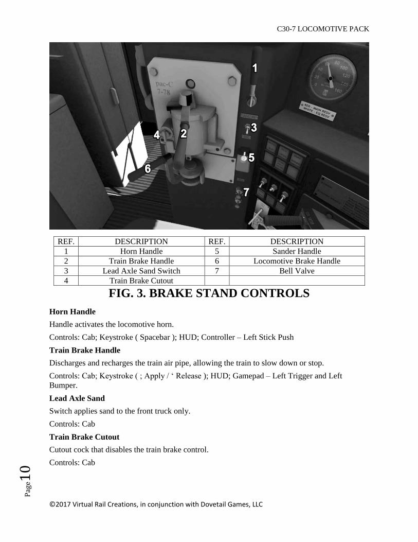
REF. DESCRIPTION REF. DESCRIPTION
1 Horn Handle 5 Sander Handle
2 Train Brake Handle 6 Locomotive Brake Handle
3 Lead Axle Sand Switch 7 Bell Valve
4 Train Brake Cutout
FIG. 3. BRAKE STAND CONTROLS
Horn Handle
Handle activates the locomotive horn.
Controls: Cab; Keystroke ( Spacebar ); HUD; Controller – Left Stick Push
Train Brake Handle
Discharges and recharges the train air pipe, allowing the train to slow down or stop.
Controls: Cab; Keystroke ( ; Apply / ‘ Release ); HUD; Gamepad – Left Trigger and Left
Bumper.
Lead Axle Sand
Switch applies sand to the front truck only.
Controls: Cab
Train Brake Cutout
Cutout cock that disables the train brake control.
Controls: Cab
C30-7 LOCOMOTIVE PACK
©2017 Virtual Rail Creations, in conjunction with Dovetail Games, LLC
Pag
e11
Sander Handle
Activates sanding for both locomotive trucks
Controls: Cab; Keystroke ( X ); HUD
Independent Brake
Brake for the locomotive only.
Controls: Cab; Keystroke ( [ Apply / ] Release ); HUD
Bell
Pull valve controls the exterior warning bell.
Controls: Cab; Keystroke ( B ); HUD; Gamepad – (A) then Left/Right directional pad to select.

C30-7 LOCOMOTIVE PACK
©2017 Virtual Rail Creations, in conjunction with Dovetail Games, LLC
Pag
e12
REF. DESCRIPTION REF. DESCRIPTION
1 Accessory Display 4 Message Display
2 Selector Button 5 Brake-Pipe Display
3 Power Indicator 6 ID Code Entry
FIG. 4. HEAD OF TRAIN DEVICE
Accessory Display
Selector Button
This allows the operator to choose between Acceleration, Distance Counter, and Length of Train
functions.
Controls: Cab
Power Indicator
Message Display
Brake Pipe Pressure Display
Selector Button
Roller control that allows the operator to input the syncing code for the End of Train Device.
Controls: Cab
C30-7 LOCOMOTIVE PACK
©2017 Virtual Rail Creations, in conjunction with Dovetail Games, LLC
Pag
e13
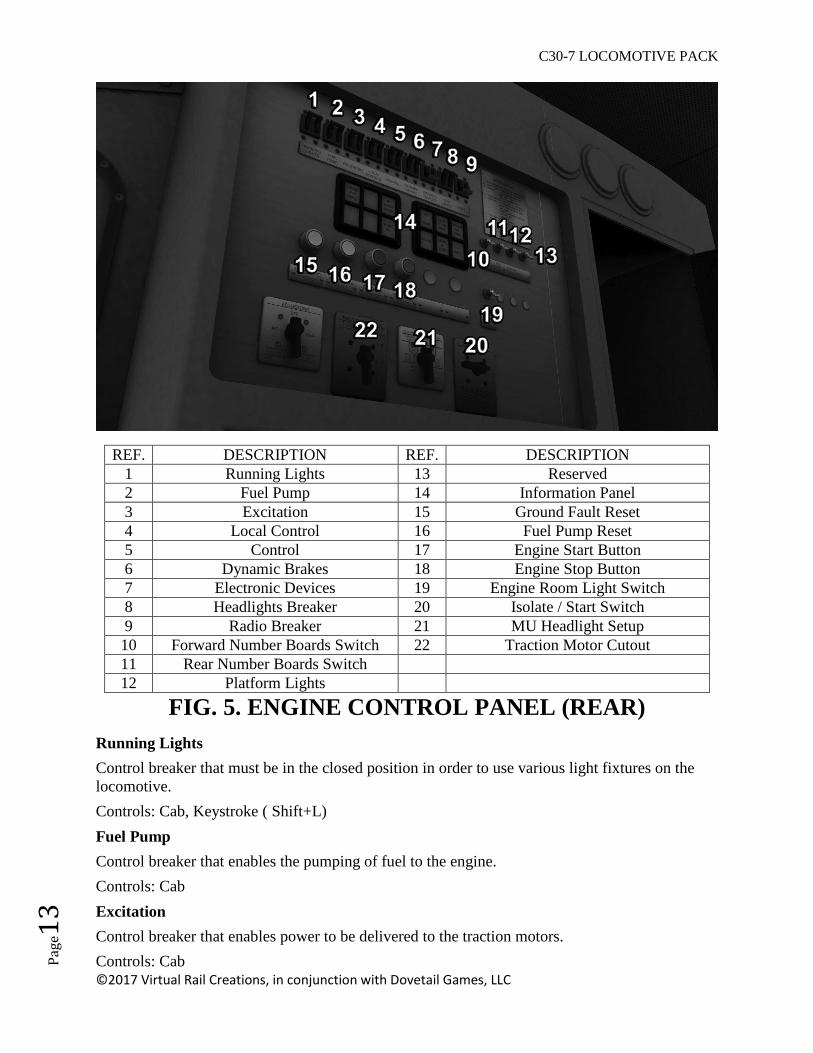
REF. DESCRIPTION REF. DESCRIPTION
1 Running Lights 13 Reserved
2 Fuel Pump 14 Information Panel
3 Excitation 15 Ground Fault Reset
4 Local Control 16 Fuel Pump Reset
5 Control 17 Engine Start Button
6 Dynamic Brakes 18 Engine Stop Button
7 Electronic Devices 19 Engine Room Light Switch
8 Headlights Breaker 20 Isolate / Start Switch
9 Radio Breaker 21 MU Headlight Setup
10 Forward Number Boards Switch 22 Traction Motor Cutout
11 Rear Number Boards Switch
12 Platform Lights
FIG. 5. ENGINE CONTROL PANEL (REAR)
Running Lights
Control breaker that must be in the closed position in order to use various light fixtures on the
locomotive.
Controls: Cab, Keystroke ( Shift+L)
Fuel Pump
Control breaker that enables the pumping of fuel to the engine.
Controls: Cab
Excitation
Control breaker that enables power to be delivered to the traction motors.
Controls: Cab
C30-7 LOCOMOTIVE PACK
©2017 Virtual Rail Creations, in conjunction with Dovetail Games, LLC
Pag
e14
Local Control
Control breaker that enables control from the lead motor.
Controls: Cab
Control
Control breaker that enables the Master Controller.
Controls: Cab
Dynamic Brake
Control breaker that enables the Dynamic Brake controller.
Controls: Cab
Electronic Devices
Control breaker that enables optional electronic equipment, such as the HTD.
Controls: Cab
Headlights
Control breaker that enables control of forward and rear headlights.
Controls: Cab
Radio
Control breaker that enables optional radio equipment.
Controls: Cab
Forward Number Boards
Switch for turning on the forward number ID lights.
Controls: Cab; Keystroke ( K )
Rear Number Boards
Switch for turning on the rear number ID lights.
Controls: Cab; Keystroke ( Shift+K )
Platform Lights
Switch for turning on the locomotive deck and step lights.
Controls: Cab; Keystroke ( Shift+D )

C30-7 LOCOMOTIVE PACK
©2017 Virtual Rail Creations, in conjunction with Dovetail Games, LLC
Pag
e15
Information Panel
These following are engine fault indicator lights.
1. Ground Fault (White) – Indicates that electricity is flowing through the frame of the
locomotive to ground. To reset, place the Throttle in Idle, allow the RPM’s to fall to
idle level, then press the Ground Fault Reset button ( #15 ) to reset. If the ground fault
occurs again within the same operating session, then the locomotive should not be
used until shop personnel can locate and fix the problem.
2. Replay Tripped (White) – Indicates a possible alternator failure, and will result in
reduced locomotive power. To reset, place the Throttle in Idle, allow the RPM’s to
fall to idle level, then press the Ground Fault Reset button ( #15 ) to reset. If the fault
occurs again within the same operating session, then the locomotive should not be
used until shop personnel can locate and fix the problem.
3. No Battery Charge (Blue) – Indicates that the batteries are not being charged. This
light will also illuminate if the locomotive is in shutdown condition and the Battery
Disconnect breaker is still closed.
4. Self-Load Box (White) – Indicates that the locomotive is in self-load test mode. The
locomotive will not operate properly under this condition.
5. Reduced Excitation (White) – Indicates that less than optimal current is being
supplied to the traction motors. The locomotive will operate at reduced power, and
the Reduced Excitation indicator will come on when the power handle is put in Idle.
The locomotive may continue to operate depending upon rules of the particular
railroad.
6. Locked Axle (White) – Indicates one of the locomotive axles has locked down. Power
will be removed from the traction motors to prevent further damage. The locomotive
may continue to operate if the locked axle can be isolated. After inspecting for a
locked axle, follow the procedure for using the Traction Motor Cutout (pg. 16) to
remove the damaged traction motor/axle from service.
7. Hot Engine (Red) – Indicates a condition in which the lubricating oil and/or the
coolant exceed specified heat ratings. If this condition is prolonged it may result in
damage and shutdown to the engine.
8. Engine System Maintenance (White) – Indicates that a fault has occurred. Will stay
on until reset by shop mechanical personnel.
9. Governor Shutdown (Orange) – Indicates that the Governor has faulted due to a low
engine water or oil condition. This can be confirmed by checking the Lube Oil gauge
in the starting compartment, and Engine will operate at reduced power.
10. Overpower (Red) – Indicates that a crank case overpressures fault has occurred. The
engine will shut down and will not restart.
11. Engine Air Filter (Red) – Indicates obstruction of the air filters. It may be possible to
clear whatever debris is blocking the intakes. Place the Throttle in idle and stop the
locomotive. After inspecting and removing any debris that may be found, press the
Engine Air Filter indicator to reset the fault and return to normal operation.
12. Hot Diode (Red) – Indicates that one or more of the rectifiers has reached an over-
temperature condition. The locomotive will operate at reduced power under this
condition. After the diodes have been given time to cool, place the throttle in idle and
press the Hot Diode indicator to reset the fault and return to normal operation.

C30-7 LOCOMOTIVE PACK
©2017 Virtual Rail Creations, in conjunction with Dovetail Games, LLC
Pag
e16
Ground Fault Reset
Push button to reset ground faults.
Controls: Cab
Fuel Pump Reset
Push button to reset fuel pump or fuel breaker faults.
Controls: Non-Interactive
Engine Start Button
Easy mode engine start.
Controls: Cab; Keystroke ( Z ); Gamepad ( Right Stick Push In )
Engine Stop Button
Easy mode engine shut down.
Controls: Cab, Keystroke ( Ctrl+Z )
Engine Room Light Switch
Turns on the engine room light.
Controls: Cab
Isolate / Start Switch
Controls the locomotive Start and Run modes. Must be in Start/Isolate in Expert Mode to start
the Engine, then must be turned to Run.
Controls: Cab
MU Headlight Setup
Controls the headlight positions for lead and trailing units.
Controls: Non-Interactive
Traction Motor Cutout
This switch controls removal of traction motors from service. The motors must be removed in
pairs, so locomotive power will be cut by 1/3rd
. In order to use this switch, the Engine Throttle
must be in idle, the Engine must be stopped, and the Start/Isolate switch must be in the “Start”
position. After cutting out the desired traction motors, move the Start/Isolate switch back to the
“Run” position.
Controls: Cab
C30-7 LOCOMOTIVE PACK
©2017 Virtual Rail Creations, in conjunction with Dovetail Games, LLC
Pag
e17
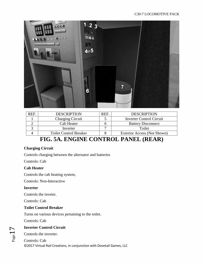
REF. DESCRIPTION REF. DESCRIPTION
1 Charging Circuit 5 Inverter Control Circuit
2 Cab Heater 6 Battery Disconnect
3 Inverter 7 Toilet
4 Toilet Control Breaker 8 Exterior Access (Not Shown)
FIG. 5A. ENGINE CONTROL PANEL (REAR)
Charging Circuit
Controls charging between the alternator and batteries
Controls: Cab
Cab Heater
Controls the cab heating system,
Controls: Non-Interactive
Inverter
Controls the inveter.
Controls: Cab
Toilet Control Breaker
Turns on various devices pertaining to the toilet.
Controls: Cab
Inverter Control Circuit
Controls the inverter.
Controls: Cab

C30-7 LOCOMOTIVE PACK
©2017 Virtual Rail Creations, in conjunction with Dovetail Games, LLC
Pag
e18
Battery Disconnect
This knife switch disconnects the batteries from the locomotive charging system. This should
only be opened if locomotive is undergoing maintenance.
Controls: Cab
Toilet
Toilet.
Controls: Non-Interactive
Exterior Access
Access door to the toilet and cab compartments from outside of the locomotive.
Controls: Cab

C30-7 LOCOMOTIVE PACK
©2017 Virtual Rail Creations, in conjunction with Dovetail Games, LLC
Pag
e19
REF. DESCRIPTION REF. DESCRIPTION
1 Turbocharger Gauge 5 Ready Indicator
2 Fuel PSI Gauge 6 Lube / Prime Button
3 Lube PSI Gauge 7 Engine Start Button
4 Wait Indicator
FIG. 6. ENGINE START COMPARTMENT
Turbocharger Gauge
Shows the amount of turbocharger pressure available during engine operation.
Fuel PSI Gauge
Shows the amount of pressure in the fuel delivery system.
Lube PSI Gauge
Shows the amount of pressure in the lubrication pumping system.
Wait Indicator
This tells the operator the status of the engine during the starting process.
Ready Indicator
This tells the operator that the engine is ready to be started.
Lube/Prime Button
The button to use to prime the engine before startup.
Controls: Cab
Engine Start Button
Pressing this button after the lube/prime cycle completes will start the engine.
Controls: Cab

C30-7 LOCOMOTIVE PACK
©2017 Virtual Rail Creations, in conjunction with Dovetail Games, LLC
Pag
e20
MISCELLANEOUS CONTROLS
Sunshield Visors
Located above the operator forward window and above the rider door, these can be pulled down
to block sunlight from blinding the occupants.
Controls: Cab
Cab Interior Lights
Located above the operator / rider seats, these can be switched on to provide illumination in
darkened conditions. The Running Lights breaker on the ECP must be closed before these lights
will become active.
Controls Conductor: Cab; Keystroke ( Ctrl+L )
Controls Engineer: Cab; Keystroke ( L )
Wipers
The wipers can be turned on from the pull-switch positions above the operator / rider seats.
Controls: Cab; Keystroke ( V ); HUD; Gamepad – (A) then directional pad to choose control.
Handbrake
The handbrake wheel is located on the short nose of the unit on the operator’s side.
Controls: Cab; Keystroke ( / ); HUD; Gamepad – (A) then directional pad to choose control.
C30-7 LOCOMOTIVE PACK
©2017 Virtual Rail Creations, in conjunction with Dovetail Games, LLC
Pag
e21
PRE-ENGINE STARTUP
CONTROLS FOR MULTIPLE UNITS
These units are set up so that control of an entire MU consist can be done from the primary
(front) locomotive. If you try to control the train from any of the trailing units in the consist after
the primary unit has been started, the locomotives will shut down and restart with the cab of the
locomotive that you are currently in becoming the primary unit.
It has been noted that in some cases it may be desirable to have lights or other accessories in the
trailing units to be in the on position. If this is the case, then use the following manual procedure
to activate them without switching the primary unit off.
Before Startup:
If in the beginning of the Scenario the locomotives have not been started, then use CTRL + or
CTRL - to move between the cabs of the engines. You may turn on whatever accessories are
necessary. Be sure that the Battery Disconnect for each unit is engaged and that the proper circuit
breakers are in the “on” position. For example, if you want to run the Dim Lights on a trailing
unit, then the Headlights Breaker must be on.
After Startup:
If you have already started the consist, or it is Auto-started at the beginning of the scenario,
moving into the cab of a trailing unit will shut down the consist. Instead, wait until after the train
has started moving to move between trailing cabs and turn on any desired accessories. However,
if you touch or move any primary controls (brake, throttle, selector, reverser) while the train is
running, the game will assume you are taking control of the train from the cab of the selected
unit and will shut down the engines.
STARTING ENGINE
SIMPLE MODE
In simple mode, the locomotive will already be started and all necessary controls switched on to
allow for immediate control. This control mode is best for using a game-pad type controller.
However, in this mode you will lose some of the advanced functions and physics this locomotive
has to offer.
INTERMEDIATE MODE
For quick start-up in Expert Mode, press the “Engine Start” control on the rear control panel.
This will throw all necessary switches into their “On” positions. However, you will need to
check your auxiliary switches (Lights, Headlights, etc.) to be sure they are on. Wait until the
engine has attained 450 RPM before operating the unit.

C30-7 LOCOMOTIVE PACK
©2017 Virtual Rail Creations, in conjunction with Dovetail Games, LLC
Pag
e22
EXPERT MODE
Before attempting to start the locomotive:
1). Move the Engine Control switch to the “Start/Isolate” position.
2). Close the following breakers on the rear control panel (FIG. 5):
a. Fuel Pump
b. Excitation
c. Local Control
d. Control
e. Dynamic Brake
3). Close the following breakers on the rear auxiliary control panel (FIG 5A):
f. Inverter
g. Charging Circuit
h. Inverter Control Circuit
NOTE: The breaker box below the auxiliary control panel should be checked to be sure that the
Battery Disconnect is engaged. This disconnect switch should only be opened if maintenance is
being performed on the engine electric circuit.
4). Close the Gen Field, Fuel Pump, and Control breakers on upper right side of the
Master Controller (FIG 2A).
5). Once these controls are active, move to the first set of doors at the engine
compartment. Open them and locate the Remote Start pendant (FIG 6).
6.) Press the Pre-lube/Prime button on the pendant and hold. This will begin circulating
oil through the engine. When this is finished, the “Ready” light will illuminate and the
Prime Pump will begin feeding fuel to the engine.
7.) Once the Prime has finished, press and hold the “Start” button for two seconds, until
the engine begins generating RPM.
8.) Back inside the cab, on the rear cabinet (FIG 5), turn the isolate switch to run before
operating engine.

C30-7 LOCOMOTIVE PACK
©2017 Virtual Rail Creations, in conjunction with Dovetail Games, LLC
Pag
e23
EXPERT MODE - TROUBLESHOOTING STARTUP ISSUES
- The engine will fail start-up if the Lube/Prime button is held longer than necessary. A
two minute cool down period is required before trying to start the engine again.
- If “Wait” light does not illuminate when pressing the prime button, go back and check to
be sure that all required breakers have been closed.
- If the Lube Prime cycle completes but the oil and fuel pressures drop when the “Start”
button is pressed, the engine will start and immediately shut down. Check all required
breakers to be sure they have been closed.
STARTUP FOR SCENARIO DEVELOPERS:
By default, the C30-7 locomotive is unpowered at the start of a scenario. If you wish to have the
locomotives start automatically at the beginning of a scenario without user input, then you need
to insert the following code into your scenario script and link it to the scenario through the
Timetable Editor:
if event == "boarding" then
SysCall ( "PlayerEngine:SetControlValue", "ShortcutStartup", 0, 1 );
return TRUE;
end
In the first line, “boarding” is a name that links the script command to the Timetable Editor. A
simple message trigger with this name placed in it is usually enough to start the locomotive. You
could also use the timestamp to trigger the startup later, or include a message to the player.
PRE-OPERATION
SETTING UP THE EOT
The HTD (Head-of-Train-Device) supplements the information that is already available to train
personnel via the console controls. Using the HTD, the train crew can monitor conditions
throughout the entire train and act accordingly. Please note that even if the HTD is not synced to
the EOT, it will still monitor brake pipe pressure and alert accordingly if the pressure in the
brake pipe begins to fall.
An End of Train device is provided to mark the end of the train. On the prototype, this device
marks the end of the train for visibility to other railroad crews, and also monitors train length and
air-pipe pressure. Of note, this model replicates a battery powered prototype. To conserve
battery power, the EOT does not flash in daytime conditions.

C30-7 LOCOMOTIVE PACK
©2017 Virtual Rail Creations, in conjunction with Dovetail Games, LLC
Pag
e24
To set up the EOT that is provided for Train Simulator, use the following procedure:
1.) If the train does not already have an EOT, switch to the Scenario Editor.
2.) From the Freight Car filter, select End of Train Device.
3.) Place the EOT on the tracks. In actuality, this is a 40’ long invisible freight car with
an EOT on the end. Manipulate the EOT just as you would a freight car. Grab the
EOT to move along the track or to turn the EOT to the correct end for use.
C30-7 LOCOMOTIVE PACK
©2017 Virtual Rail Creations, in conjunction with Dovetail Games, LLC
Pag
e25
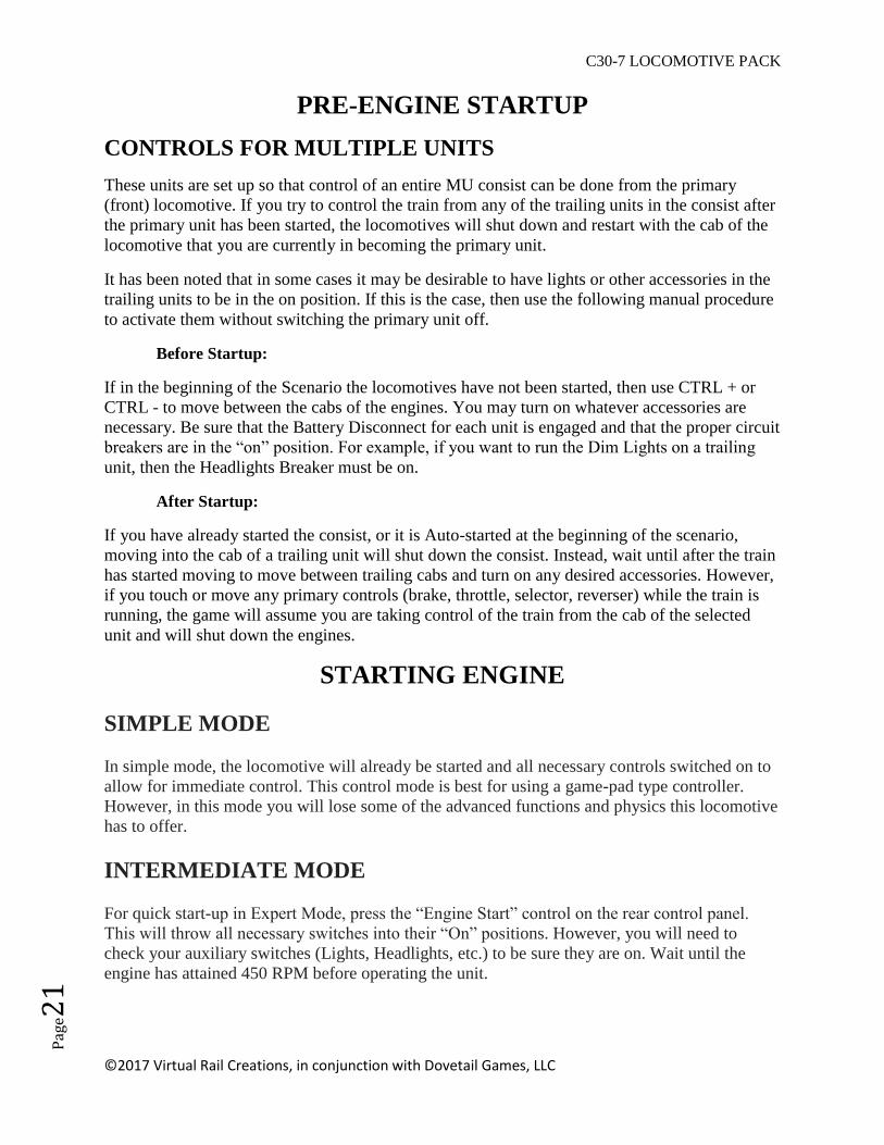
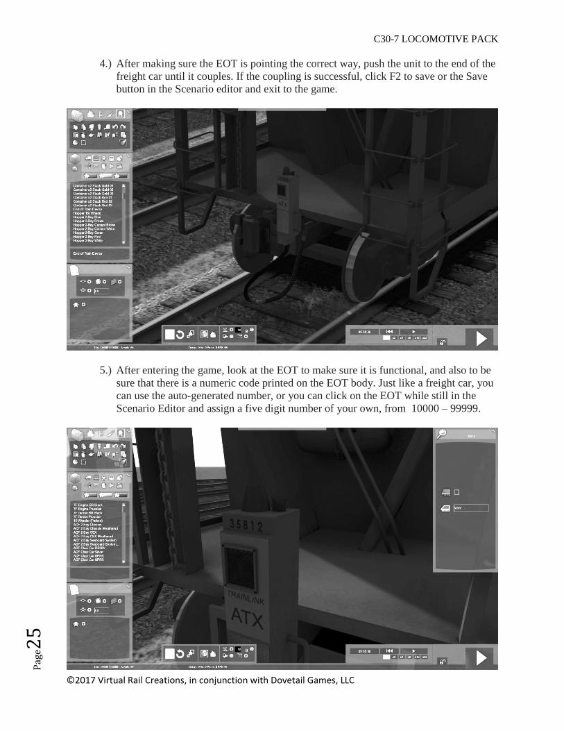
4.) After making sure the EOT is pointing the correct way, push the unit to the end of the
freight car until it couples. If the coupling is successful, click F2 to save or the Save
button in the Scenario editor and exit to the game.
5.) After entering the game, look at the EOT to make sure it is functional, and also to be
sure that there is a numeric code printed on the EOT body. Just like a freight car, you
can use the auto-generated number, or you can click on the EOT while still in the
Scenario Editor and assign a five digit number of your own, from 10000 – 99999.
C30-7 LOCOMOTIVE PACK
©2017 Virtual Rail Creations, in conjunction with Dovetail Games, LLC
Pag
e26
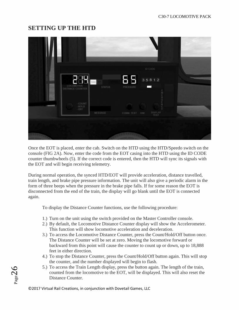
SETTING UP THE HTD
Once the EOT is placed, enter the cab. Switch on the HTD using the HTD/Speedo switch on the
console (FIG 2A). Now, enter the code from the EOT casing into the HTD using the ID CODE
counter thumbwheels (5). If the correct code is entered, then the HTD will sync its signals with
the EOT and will begin receiving telemetry.
During normal operation, the synced HTD/EOT will provide acceleration, distance travelled,
train length, and brake pipe pressure information. The unit will also give a periodic alarm in the
form of three beeps when the pressure in the brake pipe falls. If for some reason the EOT is
disconnected from the end of the train, the display will go blank until the EOT is connected
again.
To display the Distance Counter functions, use the following procedure:
1.) Turn on the unit using the switch provided on the Master Controller console.
2.) By default, the Locomotive Distance Counter display will show the Accelerometer.
This function will show locomotive acceleration and deceleration.
3.) To access the Locomotive Distance Counter, press the Count/Hold/Off button once.
The Distance Counter will be set at zero. Moving the locomotive forward or
backward from this point will cause the counter to count up or down, up to 18,888
feet in either direction.
4.) To stop the Distance Counter, press the Count/Hold/Off button again. This will stop
the counter, and the number displayed will begin to flash.
5.) To access the Train Length display, press the button again. The length of the train,
counted from the locomotive to the EOT, will be displayed. This will also reset the
Distance Counter.

C30-7 LOCOMOTIVE PACK
©2017 Virtual Rail Creations, in conjunction with Dovetail Games, LLC
Pag
e27
6.) Press the Count/Hold/Off button again to return to the Accelerometer.
NOTE: The EOT is currently designed to work with cars that can pass consist messages from
the rear of the train to the HOTD, and cars that are generally available for Train Simulator.
Currently, the cars that can pass consist messages and sync up with the numbers on the EOT are:
- 2 Bay ACF Hoppers and CSX 100Ton Coal Gondola that are supplied with this
package.
- 100 Ton Open Top Gondolas that come with the Chessie U30C package (sold
separately).
All other cars that cannot pass consist messages can sync up with the HOTD using the following
hardwired code: 70186
OPERATION
Simple / Intermediate Modes
1. Place the Reverser in the forward or reverse position.
2. Move the Train and Independent braking lever to release.
3. Move the Power Lever to the desired position to begin moving the locomotive.
Expert Mode
1. After the startup procedure is complete, move the Engine Control switch on the rear
control panel to “Run”.
2. Place the Reverser in the forward or reverse position.
3. Move the Train and Independent braking lever to release.
4. Move the Throttle to the desired position to begin moving the locomotive.
Dynamic Braking
1. Move the Throttle to the “Idle” position.
2. Move the Reverser lever to either the forward or reverse position.
3. Grab the Dynamic Brake portion of the Power Lever and move it to Setup. Wait for
10 seconds for the brakes to activate, then move to the desired position.
CONTROL NOTES – ALL UNITS
WARNING LIGHTS
Warning lights are defined as any light that has been added to the unit for the sole purpose of
enhancing the safety of the train crew and general public by calling attention to the fact that a
train is approaching.
On this unit, the HEADLIGHTS breaker must be in the closed position before operation warning
lights.

C30-7 LOCOMOTIVE PACK
©2017 Virtual Rail Creations, in conjunction with Dovetail Games, LLC
Pag
e28
RUNNING LIGHTS
Running lights on these locomotives include step lights, number boards, engine compartment
lights, toilet lights, and any other light that provides access for crew-related functions.
In order to operate these lights, the RUNNING LIGHTS breaker on the rear control panel must
be in the closed position.
EMERGENCY BRAKE RECOVERY
If the emergency brake is applied, from either the Engineer or Conductor stations, a penalty time
is enacted to allow the brake system to recharge. In order to recover from an E-brake application,
you must hold the Train Brake handle in Emergency for at least 1 minute. Afterwards, hold the
train brake in “Suppression” until the PCS light goes off. The unit will not generate power again
until the Pneumatic Control Switch resets.
OVERSPEED
The maximum powered speed for this locomotive is 70mph. Operation of the unit above the
maximum speed can result in damage to engine or traction components. The locomotive is
equipped with over speed control to prevent this. Once the unit has reached 70 mph, the PCS
Relay will be tripped in an automatic attempt to reduce unit speed.
PCS RELAY AND RESET
These units are equipped with a PCS (pneumatic control switch) relay that, in the event the train
exceeds the maximum locomotive speed, will dump the brake pipe and reset the throttle to zero,
no matter its current position. If the PCS relay is tripped, you must place the throttle to Notch 0,
place the Reverser handle in neutral, and place the Train Brake in Suppression. Once the speed of the
train has dropped below the maximum tolerable limit, the PCS relay will be reset.
The PCS reset can also be triggered if an electrical fault causes the AC Control breaker to disengage.
You will need to make sure that this breaker is engaged before attempting a reset.

C30-7 LOCOMOTIVE PACK
©2017 Virtual Rail Creations, in conjunction with Dovetail Games, LLC
Pag
e29
THE GENERAL ELECTRIC C30-7 FOR TRAIN SIMULATOR
This package features the C30-7 locomotive in CSX Transportation licensed paint liveries, and
contains the following downloadable content for use with Dovetail Game’s Trains Simulator
2017 PC and video game:
C30-7 : CSX
C30-7 : CSX Weathered ( Light and Heavy )
40' CSX Two-Bay covered hopper, clean and weathered.
40' Chessie System Two-Bay covered hopper, clean and weathered.
40' Seaboard System Two-Bay covered hopper, clean and weathered.
45’ CSX Three-Bay 100 Ton coal hopper.
End of Train Device
Quick Drive scenario for each locomotive.
Career Scenarios
SCENARIOS
C30-7 01. Sandbaggin’ – Make up a loaded train at the local Sand Plant and take it south.
C30-7 02. Hobo Special - Pick up empty loads from sidings along the division and take them to
Jacksonville.
C30-7 03. Scrap Iron Express, Parts I and II – The company decides to retire the C30’s, but
“new” does not always mean “improved”.
QUICK DRIVE SCENARIOS
Each locomotive is enabled for Quick Drive. Simply click on the Quick Drive tile in Train
Simulator and select one of the locomotives and a route to run it on.
CREATING YOUR OWN SCENARIOS
These instructions are for creating a simple free-roam scenario using the C30-7 and freight cars.
If you want to create a more sophisticated scenario or add special instructions you should consult
the TS2016 user manual.
- After opening the Scenario Editor for the Scenario and Route of your choosing, click on the
Object Filter pane (left middle pull-out).
- Click on the Provider Filter (box with arrow on it) to bring up the filter box (right-side pullout)

C30-7 LOCOMOTIVE PACK
©2017 Virtual Rail Creations, in conjunction with Dovetail Games, LLC
Pag
e30
- Scroll down through the list of providers and make sure that "VRC" is checked, as well as C30-
7.
- Return to the object filter and click the Locomotive icon.
- Scroll through the list and choose one of the available C30-7 locomotives.
- Place the locomotive on the tracks as many times as desired.
- Add freight cars to the consist.
- Place a driver icon on the lead locomotive.
- Press F2 to save the scenario, then close it out.
- Once in the actual game, click on the locomotive to select it as your player avatar.
C30-7 LOCOMOTIVE PACK
©2017 Virtual Rail Creations, in conjunction with Dovetail Games, LLC
Pag
e31
SUPPLIED SCENARIOS CHEAT SHEETS
WARNING: SPOILERS AHEAD. If you want to play these scenarios without knowing the
outcome, stop reading now!
Scenario 01: C30-7 01. Sandbaggin’. This is a straightforward route tour scenario. You begin
your day on a siding at Northwood. After being given instructions and starting your locomotive,
you move your light engines south to the sand plant and pick up two strings of loaded freight
cars. After collecting the cars and setting your EOT, you head south to Hileah.
Tips:
- There is a northbound Amtrak train coming on the main you will be working on. It
would not be a good idea to stop that train.
- Handle the cars at the sand plant carefully. They are backed against the buffers and
can easily be derailed.
- Unless you are extremely fast in your switching, you will be passed by a southbound
freight. Be on the watch for restricted signals and equipment on the tracks ahead of
you.
Scenario 02: C30-7 02. Hobo Special. In this scenario, you will be following an Amtrak local
north. This is the weekly Hileah-to-Jacksonville empty car collector, so you will have plenty of
stops of your own to make.
Tips:
- Check your switching list to be sure that you make all of your drops and pick-ups.
- Make sure that all of your manual switches are lined correctly. The dispatcher will
give you the track that you should be on, but you and your crew are responsible for
making sure you are on that track. You will need to make sure that your route is lined
before entering the sidings to avoid collisions with static rail cars.
- Several of the sidings that you are switching will have Restricted Signal protection.
You need to ask Dispatch permission to pass them.
- The C30-7 is a slow, lumbering beast that is not meant for switching. It may take
some patience and trial and error at the controls to get the hang of making multiple
stops.

C30-7 LOCOMOTIVE PACK
©2017 Virtual Rail Creations, in conjunction with Dovetail Games, LLC
Pag
e32
Scenario 03: C30-7 03. Scrap Iron Express, Parts I and II. It’s 2003 and CSX is retiring its
fleet of Dash 7’s. Unfortunately, someone in the shop pencil whipped a work order, and the Dash
8 assigned to the move is not exactly up to the task.
Tips:
- This is a two part “no win” scenario. The first part will see multiple failures en-route
to Waycross. The second part solves the issue by firing up one of the diesels that are
about to be scrapped to continue the journey.

C30-7 LOCOMOTIVE PACK
©2017 Virtual Rail Creations, in conjunction with Dovetail Games, LLC
Pag
e33
APPENDIX 1: CREATING LOCOMOTIVE FAULTS IN
SCENARIOS
The C30-7 Locomotive has been scripted to take advantage of as many realistic controls as is
possible in this game. This includes a number of errors and faults that prototype railroad crews
may encounter when operating this locomotive. These faults, described on page 15, can be
triggered through scenario scripting in Train Simulator.
CONTROL NAMES
In order to trigger locomotive faults, you first must know the Control Names that must be
plugged into the script to activate them. The following are the fault names that are used. They
must be put into the script exactly as written here:
GroundFault
OverloadRelay
Fault:ReducedExcitation
LockedAxle
HotEngineLight
Governer Fault
Failure:CrankCaseOverpressure
EngineAirFilter
HotDiodes

C30-7 LOCOMOTIVE PACK
©2017 Virtual Rail Creations, in conjunction with Dovetail Games, LLC
Pag
e34
SETTING UP THE SCENARIO
After setting up your consist with the C30-7 as the player locomotive, you will need to do a few
things in the Scenario Editor to set up a failure.
1. You will need to set up a marker to trigger the failure. You can either use a marker that is
already present (i.e. a siding, destination, or platform marker), or you can set up a new
one. If you do set up a new one, it’s important to make it as inconspicuous as possible so
that a player who is new to the scenario will not suspect that a failure is imminent. Name
it after a nearby milepost, signal, or road crossing so it looks to be a natural part of the
route.
FIG. 7. TRIGGER MARKER
2. After your trigger marker is set up, you will need to go into the Time Table Editor and
find your consist. Insert a “Stop at Destinations” instruction and open it for editing. For
the Destination, you will need to find the marker that you just created from the dropdown
list. In this example, the marker is called MP43. For the speed, if you want your
locomotive to be moving when it hits the marker, then put in 1mph or above. And to hide
it from the player, check the “Hide in Taskbar” box.
Finally, in the Trigger Event Success field box, you need to put in a friendly name. This
name will be what hooks the fault to the script. In this example, we will put “FaultOne”
in the field.

C30-7 LOCOMOTIVE PACK
©2017 Virtual Rail Creations, in conjunction with Dovetail Games, LLC
Pag
e35
FIG. 8. DESTINATION INSTRUCTION

C30-7 LOCOMOTIVE PACK
©2017 Virtual Rail Creations, in conjunction with Dovetail Games, LLC
Pag
e36
3. Still in the Time Table Editor, got to the icon in the upper quadrant, second from the
right, the Script Editor. Teaching you how to create a script from scratch is beyond the
scope of this manual, so for starters you will want to copy and paste a copy of an already
existing script from another scenario. Once you have done this, in the script editor, click
on the “Edit” button to open the script in plain text. Notepad++ is the recommended
editor used here.
When you open the script, you will see a lot of different stuff, but all that we are worried
about comes between the word “function” and “end”. The first thing you need to do is
plug in your “hook word” from the Time Table “Stop at Destinations” marker. That word
was “FaultOne”, so that is what we are going to type in after the words “if event ==”. It
should look like this:
if event == "FaultOne" then
The next part will be our fault trigger. In the second line that begins with “SysCall”, we
are going to put in one of the Control Names that were listed earlier. Since it is a simple
fault that can be reset by the player from the engine cab, in this example we are going to
use the “GroundFault”. The line should look like this:
SysCall ( "PlayerEngine:SetControlValue", "GroundFault", 0, 1 );
What this line does is send a message to the Engine Blueprint to turn on the Ground Fault
Light. When that happens, another script that governs how the engine behaves when this
light comes on tells the locomotive what to do next. If all goes well, you have just caused
a bit of a headache for the player.
Put altogether, the script should look like this. Don’t be intimidated by this, as lines 34
and 37 are all you really need to worry about.
NOTE: In the photo the script hook word shows “GroundFaultLight”. It should read
“GroundFault”.

C30-7 LOCOMOTIVE PACK
©2017 Virtual Rail Creations, in conjunction with Dovetail Games, LLC
Pag
e37
FIG. 9. SCRIPTING HOOK
4. Now save your script and go back into the Time Table Editor. Still in the Scripting
Screen, you need to push the button that reads “Compile/Generate MD5” to make the
script active in the scenario. Do this each time that you change your script in order to
update it in the game. Now, exit out of the script editor.
5. If you are done making changes to your scenarios, click F2 to save the scenario, click OK
in the Time Table Editor to exit, and then click on the Play button in the lower left corner
to enter your scenario. Start up the locomotive and move to the marker that is set up to
make the locomotive fail. If you have done your work correctly, when you hit the marker,
the rear ECP panel should look like this, and your locomotive should lose power.

C30-7 LOCOMOTIVE PACK
©2017 Virtual Rail Creations, in conjunction with Dovetail Games, LLC
Pag
e38
FIG. 10. GROUND FAULT
COMPLICATIONS
If you want to make things a bit more difficult for the player, then you could try a few of the
following suggestions:
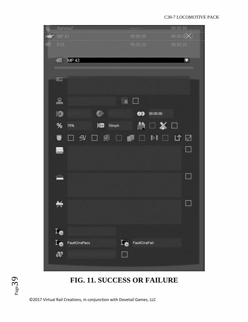
1. Create a success or failure for each event. When you create your Destination Instruction,
in addition to your success condition ( “FaultOne” ), put a failure condition in the
“Trigger Event Failure” field. Change the Speed box to “10mph”. Making these changes
would give you an and/or condition that could dictate whether the player triggers a failure
or makes it successfully past that point. It would look something like this:
C30-7 LOCOMOTIVE PACK
©2017 Virtual Rail Creations, in conjunction with Dovetail Games, LLC
Pag
e39
FIG. 11. SUCCESS OR FAILURE

C30-7 LOCOMOTIVE PACK
©2017 Virtual Rail Creations, in conjunction with Dovetail Games, LLC
Pag
e40
You would then need to change your script to look like this:
FIG. 12. SCRIPT HOOKS
What you have done is create a condition where if the player is driving the locomotive at
a speed of greater than 10mph, the scenario will not trigger the failure. But, if the
locomotive is going slower than 10mph, the failure would be triggered. This could be
very useful to simulate failures in situations where the locomotive has been running at
full power for long periods of time, such as hauling a heavy consist up Donner Pass.
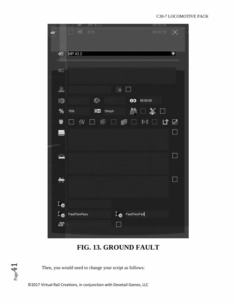
2. The Hot Engine failure is a fault that would need more in depth scripting. You would
need two points of failure for this one. The first would trigger the Hot Engine light. The
second failure point would be like the one shown in the first example and could be
loosely dependent on the first trigger.
For example: The locomotive is pulling a heavy consist up a long grade. You have done
your homework as you created the scenario, so you know that the engine is going to
experience at least ten minutes of running at maximum throttle. So, midway up the hill,
around the five minute mark, you create your first Destination Marker failure and script it
to turn on the Hot Engine Light. This is the first warning that something bad is about to
happen. The Engineer will either need to throttle back or risk burning up the traction
motors. So, a few thousand feet more up the hill, you would need to place a second
destination marker, name it, and then put in the information in the Time Table Editor like
so:
C30-7 LOCOMOTIVE PACK
©2017 Virtual Rail Creations, in conjunction with Dovetail Games, LLC
Pag
e41
FIG. 13. GROUND FAULT
Then, you would need to change your script as follows:
C30-7 LOCOMOTIVE PACK
©2017 Virtual Rail Creations, in conjunction with Dovetail Games, LLC
Pag
e42
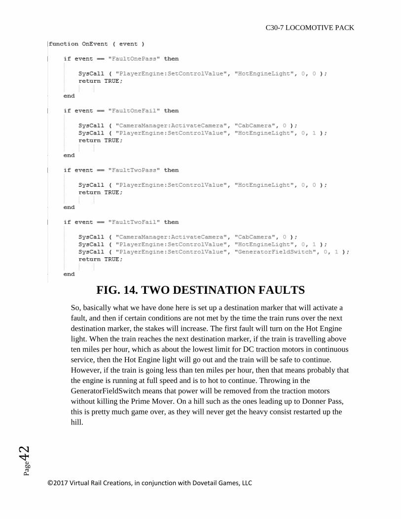
FIG. 14. TWO DESTINATION FAULTS
So, basically what we have done here is set up a destination marker that will activate a
fault, and then if certain conditions are not met by the time the train runs over the next
destination marker, the stakes will increase. The first fault will turn on the Hot Engine
light. When the train reaches the next destination marker, if the train is travelling above
ten miles per hour, which as about the lowest limit for DC traction motors in continuous
service, then the Hot Engine light will go out and the train will be safe to continue.
However, if the train is going less than ten miles per hour, then that means probably that
the engine is running at full speed and is to hot to continue. Throwing in the
GeneratorFieldSwitch means that power will be removed from the traction motors
without killing the Prime Mover. On a hill such as the ones leading up to Donner Pass,
this is pretty much game over, as they will never get the heavy consist restarted up the
hill.

C30-7 LOCOMOTIVE PACK
©2017 Virtual Rail Creations, in conjunction with Dovetail Games, LLC
Pag
e43
BIBLIOGRAPHY
- Fallen Flags Locomotive Operations Manuals: GE New Series Diesel-Electric
Locomotives.
- U Boats: General Electric’s Diesel Locomotives – Greg McDonnell.
CREDITS AND THANKS
Many thanks to the fine amatuer rail fans and professional rail workers who have
helped make this locomotive as realistic an experience as possible:
Anthony Wood
Ed Kaspriske
Eric Salter
Frank Sanfranek
CSX Transportation
The Illinois Railway Museum
The Tennessee Valley Railroad Museum