c51r/c51u bike repair manual (electronics)...c51r/c51u bike repair manual (electronics) - contents...
TRANSCRIPT

C51R/C51U Bike Repair Manual (Electronics)
C51R Bike C51U Bike
Version 1; Date: 11-24-04

C51R/C51U Bike Repair Manual (Electronics)
The C51R and C51U Bike Repair Manual (Electronics) was made as a troubleshooting guide for technicians in the field. Please send suggestions and comments to [email protected]. Thank you. Preliminary Manual - Date: 04-15-04 Version 1 – Date: 11-24-04 – Format revised, contents updated.
0

C51R/C51U Bike Repair Manual (Electronics) - Contents
Table of Contents Chapter 1 – Product and Component Illustrations 1-1-1. C51U Exercise Bicycle Picture 1-1-2. C51R Exercise Bicycle Picture 1-2-1. C51U Part Location: Display 1-2-2. C51R Part Location: Display 1-3-1. C51U Parts: Lower Half 1-3-2. C51R Parts: Lower Half 1-4-1. C51U Display Front 1-4-2. C51R Display Front 1-5-1. Display Board Front 1-5-2. Display Board Back 1-6-1. Drive Board 1-7-1. Other Electronic Components (Continued through 1-7-2) Chapter 2 – Product Functions 2-1-1. C51R/C51U Product Function Overview 2-1-2. Display Functions: Windows 2-1-3. Display Functions: Light Emitting Diode (LED) Indicators 2-1-4. Display Functions: Keys
i

C51R/C51U Bike Repair Manual (Electronics) - Contents
Table of Contents (Continued) Chapter 3 – Product Operation 3-1-1. Start Up Operation 3-1-2. User Settings (Continued through 3-1-3) 3-1-4. Program Operation 3-1-5. Quick Start Operation 3-1-6. Resistance Operation 3-1-7. Stop Operation 3-1-8. Pause/Reset Operation 3-1-9. Mode Operation Chapter 4 – Wire Connections 4-1-1. Display Board Wire Connections 4-1-2. Drive Board Wire Connections Chapter 5 – Component Placement 5-1-1. Component Placement on the Display Board 5-1-2. Display Board LED Placement 5-1-3. Display Board Cable Connections 5-2-1. Drive Board Component Placement 5-2-2. Drive Board LED Placement 5-2-3. Drive Board Wire Connections
ii

C51R/C51U Bike Repair Manual (Electronics) - Contents
Table of Contents (Continued) Chapter 6 – Troubleshooting 6-1-1. Malfunction: Display Will Not Light Up (Continued through 6-1-8) 6-2-1. Malfunction: Key Operation Error (Continued through 6-2-6) 6-3-1. Malfunction: ERR 7 (Continued through 6-3-4) 6-4-1. Malfunction: No Resistance Motor Movement (Continued through 6-4-4) 6-5-1. Malfunction: Polar Heart Rate Error (Continued through 6-5-4) 6-6-1. Malfunction: Heart Touch Rate (HTR) Reading Error (Continued through 6-6-6) 6-7-1. Malfunction: Fuse Breaks (Continued through 6-7-2) 6-8-1. Malfunction: No Speed Count (Continued through 6-8-2) Note: HTR function is not offered on C51 bikes in North America.
iii

C51R/C51U Bike Repair Manual (Electronics) - Illustrations
Chapter 1 – Product and Component Illustrations 1-1-1. C51U Exercise Bicycle Picture 1-1-2. C51R Exercise Bicycle Picture 1-2-1. C51U Part Location: Display 1-2-2. C51R Part Location: Display 1-3-1. C51U Parts: Lower Half 1-3-2. C51R Parts: Lower Half 1-4-1. C51U Display Front 1-4-2. C51R Display Front 1-5-1. Display Board Front 1-5-2. Display Board Back 1-6-1. Drive Board 1-7-1. Other Electronic Components (Continued through 1-7-2)
1-0-0

C51R/C51U Bike Repair Manual (Electronics) - Illustrations
C51U Exercise Bicycle Picture
1-1-1

C51R/C51U Bike Repair Manual (Electronics) - Illustrations
C51R Exercise Bicycle Picture
1-1-2

C51R/C51U Bike Repair Manual (Electronics) - Illustrations
C51U Part Location: Display
1-2-1

C51R/C51U Bike Repair Manual (Electronics) - Illustrations
C51R Part Location: Display
1-2-2

C51R/C51U Bike Repair Manual (Electronics) - Illustrations
C51U Parts: Lower Half
1-3-1
ResistanceMotor/VR
Reed Switch Wire
Drive Board
On/Off Switch
Transformer
Fuse

C51R/C51U Bike Repair Manual (Electronics) - Illustrations
C51R Parts: Lower Half
1-3-2
Reed Switch Wire
VR
Fuse
Drive Board
Transformer
On/Off Switch

C51R/C51U Bike Repair Manual (Electronics) - Illustrations
C51U Display Front
1-4-1

C51R/C51U Bike Repair Manual (Electronics) - Illustrations
C51R Display Front
1-4-2

C51R/C51U Bike Repair Manual (Electronics) - Illustrations
Display Board Front
1-5-1

C51R/C51U Bike Repair Manual (Electronics) - Illustrations
Display Board Back
1-5-2

C51R/C51U Bike Repair Manual (Electronics) - Illustrations
Drive Board
1-6-1

C51R/C51U Bike Repair Manual (Electronics) - Illustrations
Other Electronic Components
Part Transformer (110V) Part No. 051823020 Part Transformer (220V) Part No. 051823030
Part POLAR Receiver Part No. 111120040 Part Key Board Part No. 052420021
1-7-1

C51R/C51U Bike Repair Manual (Electronics) - Illustrations
Other Electronic Components (Continued)
Part On/Off Switch Part No. 000125020 Part Reed Switch Part No. 052427050
Part VR Set Part No. 051851041
1-7-2

C51R/C51U Bike Repair Manual (Electronics) - Functions
Chapter 2 – Product Functions 2-1-1. C51R/C51U Product Function Overview 2-1-2. Display Functions: Windows 2-1-3. Display Functions: Light Emitting Diode (LED) Indicators 2-1-4. Display Functions: Keys
2-0-0

C51R/C51U Bike Repair Manual (Electronics) - Functions
C51R/C51U Product Function Overview
Function Details Display Main Window Shows scrolling messages and resistance illustrations
Display Mode Windows Shows TIME/HR/RESISTACE LEVEL/ WATTS/DISTANCE/CAL/SPEED/RPM
Resistance LEVEL1~ LEVEL20 Operation Modes MANUAL/HILL/RANDOM/ INT1/ INT2
Heart Rate Not included in North American market KPH / MPH Display jumper JUMP1/Continuity: KPH; No continuity: MPH
USER Configurations Four user configurations: USER1~ USER4
Other Specifications: Serial number location: C51R – in back of unit, faces rear on transport handle that extends below the seat; C51U – in back of unit, faces front on frame post connected to rear stand.
On/Off switch location: C51R - in front of user at about knee level; C51U - behind user, in rear of unit, below the seat.
Power cord socket and fuse location: C51R – in front of unit, low; C52U – low under unit, toward the rear.
Fuse: 250V 0.5 Amp (length: 32mm)
2-1-1

C51R/C51U Bike Repair Manual (Electronics) - Functions
Display Functions: Windows
2-1-2
Main Window Shows scrolling
messages and resistance illustrations
MODE Window (1) TIME Lit = Shows time HR Lit = Shows heart rate RESISTACE LEVEL Lit = Shows
resistance level WATTS Lit = Shows WATTS
MODE Window (2) DISTANCE Lit = Shows
distance CAL Lit = Shows calorie
expenditure SPEED Lit = Shows speed RPM Lit = Rotations per
minute

C51R/C51U Bike Repair Manual (Electronics) - Functions
Display Functions: Light Emitting Diode (LED) Indicators
2-1-3
CAL LED lit: Shows calorie expenditure
SPEED LED lit: Shows speed
RPM LED lit: Shows rotations
i t SCAN LED lit: Scans from one readout function to the next: DISTANCE, CAL, SPEED, RPM
MANUAL LED lit: Manual operation mode is activated
HILL LED lit: Shows hill mode is activated
RANDOM LED lit: Shows random resistance mode is activated
INT1 LED lit: Shows INTERVAL 1 mode is activated
INT2 LED lit: Shows INTERVAL 2 mode is activated
DISTANCE LED lit: Shows accumulated distance
SCAN LED lit: Scans from one readout function to the next:
TIME、HR、RESISTANCE
LEVEL、RPM indicators light in
WATT LED lit: Shows WATTS
HR LED lit: Shows heart rate value
TIME LED lit: Shows exercise time duration
RESISTANCE LEVEL LED lit: Shows resistance value

C51R/C51U Bike Repair Manual (Electronics) - Functions
Display Functions: Keys
2-1-4
<MODE> Press to set MODE
(1) window display of TIME/RESISTANCE LEVEL/WATTS/SCAN
<MODE> Press to set MODE (2)
window display of DISTANCE/CAL/SPEED/RPM/SCAN
<MANUAL> Press for manual operation
<HILL> Press to run the hill workout
<RANDOM> Press to set random workout
<INT2> Press to run INTERVAL2 mode
<INT1> Press to run INTERVAL1 mode
RESISTANCE LEVEL
<▲>/<▼> Press to set
RESISTANCE LEVEL lower or higher
<RESET> Press to reset
<STOP> Press to stop action
<QUICK START> Press to start without setting personal details
<START> Press to start with personal details
<ENTER> Press to confirm your
selection

C51R/C51U Bike Repair Manual (Electronics) - Operation
Chapter 3 – Product Operation 3-1-1. Start Up Operation 3-1-2. User Settings (Continued through 3-1-3) 3-1-4. Program Operation 3-1-5. Quick Start Operation 3-1-6. Resistance Operation 3-1-7. Stop Operation 3-1-8. Pause/Reset Operation 3-1-9. Mode Operation
3-0-0

C51R/C51U Bike Repair Manual (Electronics) - Operation
3-1-1
Start Up Operation Function: 1. Start the unit. Procedure: 1. Plug power cord into the bike and appropriate wall power socket. 2. Turn on the On/Off switch. “C51” scrolls across the display. 3. Press the <START> key to operate with personal details (see User Settings on 3-1-2), or press the <QUICK START> key to immediately start exercising (see Quick Start on 3-1-5).
Start Up Display: Scrolling “C51”

C51R/C51U Bike Repair Manual (Electronics) - Operation
User Settings Function: 1. Establish user information for USER 1 through USER 4. Procedure: 1. Establish user information as follows: (a) Press the <Start> key. The USER indicator lights, and the main window shows “1”, indicating activation of USER 1 mode, as shown on the lower left.
(b) Press the RESISTANCE LEVEL<▲>/<▼>keys to select USER1 - USER4. Press the<ENTER> key to confirm your choice. 2. Establish the user weight setting as follows: (a) The WT indicator lights, indicating the activation of the weight setting mode. The left MODE window shows either a pre-set value or a weight set by another user, as shown on the lower right.
(b) Press RESISTANCE LEVEL<▲>/<▼>keys to select your weight. Press the <ENTER> key to confirm your selection. Setting range: 20~150 Kg or 45~330 LB.
User Setup: User 1 User Weight: 75 LBS
3-1-2
C51R/C51U Bike Repair Manual (Electronics) - Operation
3-1-3
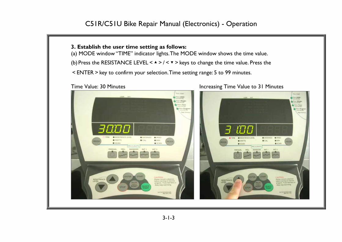
3. Establish the user time setting as follows: (a) MODE window “TIME” indicator lights. The MODE window shows the time value.
(b) Press the RESISTANCE LEVEL<▲>/<▼>keys to change the time value. Press the
<ENTER>key to confirm your selection. Time setting range: 5 to 99 minutes. Time Value: 30 Minutes Increasing Time Value to 31 Minutes

C51R/C51U Bike Repair Manual (Electronics) - Operation
3-1-4
Program Operation Function: 1. Select PROGRAM operation modes. Procedure: 1. After turning on the unit and establishing user settings, press any PROGRAM key to activate that program. The illustration on the lower left shows the display with a MANUAL program selected. (MANUAL program LED lights; the main window shows the resistance level.) The illustration on the right shows a user selecting a STAIR program. (The STAIR program LED lights; the main window shows resistance.)
Manual Program, Resistance Level 1 Stair Program, Resistance Illustration

C51R/C51U Bike Repair Manual (Electronics) - Functions
3-1-5
Quick Start Operation Function: 1. Start exercising quickly, without setting user details. Procedure: 1. After starting up the unit, the display shows “C51”.
2. Press the<QUICK START>key. The display appears as shown below. Note that PROGRAM LEDs do not light.
3. Press RESISTANCE LEVEL <▲>/<▼> keys to set the resistance level. The main window shows the RESISTANCE LEVEL. The higher the dots, the higher the resistance level.

C51R/C51U Bike Repair Manual (Electronics) - Operation
3-1-6
Resistance Operation Function: 1. Set and show resistance levels. Procedure: When the RESISTANCE LEVEL LED lights:
1. Press the RESISTANCE LEVEL<▲>key. Values in the RESISTANCE LEVEL window (lower left) increase. Actual resistance increases.
2. Press the RESISTANCE LEVEL<▼> key. Values in the RESISTANCE LEVEL window (lower right) decrease. Actual resistance decreases. Resistance level range: LEVEL 1 – 20.
Increasing Resistance Decreasing Resistance

C51R/C51U Bike Repair Manual (Electronics) - Operation
3-1-7
Stop Operation Function: Stop unit operation.
Operation: 1. When the<STOP>key is pressed, the display dot matrix shows “T”. TIME and DISTANCE LEDs light, and their respective values appear (lower left). 2.TIME and DISTANCE values appear simultaneously for 4 seconds. 3. HR and CAL LEDs light, and their respective values appear for 4 seconds (lower right). 4.The display cycles twice as explained in steps 2 and 3, then “C51” scrolls across the display.
Time and Distance Values Heart Rate and Calorie Values

C51R/C51U Bike Repair Manual (Electronics) - Operation
3-1-8
Pause/Reset Operation Function: 1. Operate pause and reset functions.
Procedure: 1. Press the<PAUSE/RESET>key. The word “PAUSE” scrolls across the display
(lower left). Press the<START>key or start exercising to recover the time count.
2. Press and hold the<PAUSE/RESET>key for two seconds. “C51” scrolls across the display (as shown on the right).
Pause Function Reset Function

C51R/C51U Bike Repair Manual (Electronics) - Operation
Mode Operation Function: 1. Show values for TIME, HR, RESISTANCE LEVEL, WATTS, DISTANCE, CAL SPEED, RPM, SCAN.
Procedure: 1. Press the left <MODE> key to see values for TIME, HR, RESISTANCE LEVEL, WATTS, SCAN (lower left).
2. Press the right <MODE> key to see values for DISTANCE, CAL, SPEED, RPM, SCAN (lower right).
Left Mode Key Right Mode Key
3-1-9

C51R/C51U Bike Repair Manual (Electronics) - Connections
Chapter 4 – Wire Connections 4-1-1. Display Board Wire Connections 4-1-2. Drive Board Wire Connections
4-0-0

C51R/C51U Bike Repair Manual (Electronics) - Connections
Display Board Wire Connections
DISPLAY BOARDKEY BOARD
POLARBOARD
DRIVE BOARD
4-1-1

C51R/C51U Bike Repair Manual (Electronics) - Connections
Drive Board Wire Connections
DISPLAY BOARD
DRIVE BOARD
RESISTANCEVR & MOTOR
REEDSWITCH
WIRE
FUSE
ON/OFFSWITCH
TRANSFORMER
POWERCORD
4-1-2

C51R/C51U Bike Repair Manual (Electronics) - Placement
Chapter 5 – Component Placement 5-1-1. Component Placement on the Display Board 5-1-2. Display Board LED Placement 5-1-3. Display Board Cable Connections 5-2-1. Drive Board Component Placement 5-2-2. Drive Board LED Placement 5-2-3. Drive Board Wire Connections
5-0-0

C51R/C51U Bike Repair Manual (Electronics) - Placement
Component Placement on the Display Board
5-1-1

SPORTS ART INDUSTRIAL CO., LTD.
C51R/C51U Display Board LED Placement and Explanation
DISTANCE RESISTANCE LEVEL
CAL WATTS
SPEED TIME
RPM HR
SCAN SCAN
HILL MANUAL RANDOM INT1 INT2
5-1-2

SPORTS ART INDUSTRIAL CO., LTD.
C51R/C51U Display Board Cable Connections
CN1 To drive board
CN2 To POLAR board
CN3 To HTR cable
(not used in North American Market)
CN4 To key board
5-1-3

C51R/C51U Bike Repair Manual (Electronics) - Placement
Drive Board Component Placement
5-2-1

C51R/C51U Bike Repair Manual (Electronics) - Placement
Drive Board LED Placement
5-2-2
LED5 - CLK Indicator Flashes or lights to
indicate incoming reed switch signal.
LED3 – Level Up Indicator When lit, VR motor
operates. Resistance increases.
LED4 – Level Down Indicator When lit, VR motor
operates. Resistance decreases.
LED2 - Motor Power Indicator Lit indicates power is available
to the motor.
LED1 - Power Indicator Lit indicates power to
the board.

C51R/C51U Bike Repair Manual (Electronics) - Placement
Drive Board Wire Connections
5-2-3
CN2 to
transformer
CN1 to power
cord
CN5 to reed
switch
CN4 to resistance
VR/motor
CN3 to display

C51R/C51U Bike Repair Manual (Electronics) - Troubleshooting
Chapter 6 – Troubleshooting 6-1-1. Malfunction: Display Will Not Light Up (Continued through 6-1-8) 6-2-1. Malfunction: Key Operation Error (Continued through 6-2-6) 6-3-1. Malfunction: ERR 7 (Continued through 6-3-4) 6-4-1. Malfunction: No Resistance Motor Movement (Continued through 6-4-4) 6-5-1. Malfunction: Polar Heart Rate Error (Continued through 6-5-4) 6-6-1. Malfunction: Heart Touch Rate (HTR) Reading Error (Continued through 6-6-6) 6-7-1. Malfunction: Fuse Breaks (Continued through 6-7-2) 6-8-1. Malfunction: No Speed Count (Continued through 6-8-2) Note: HTR function is not offered on C51 bikes in North America.
6-0-0

C51R/C51U Bike Repair Manual (Electronics) - Troubleshooting
Malfunction: Display Will Not Light Up Turn on unit power switch. Display board does not beep, and display does not light up.
Operation Diagram
DISPLAY BOARD
DRIVE BOARD
FUSE
ON/OFFSWITCH
POWERCORD
TRANSFORMER
6-1-1

C51R/C51U Bike Repair Manual (Electronics) - Troubleshooting
Normal Operation
Order Part Operation 1 Power Cord 1.The cord supplies power from the wall power socket to the unit.
2 Fuse and Fuse Holder
1.Power passes through the fuse. The fuse protects components. When current is too high, the fuse breaks.
3 On/Off Switch 1.When the On/Off Switch is set to “0”, there is no power to the drive board. 2.When the On/Off Switch is set to “1”, power travels AC1 and AC2 wires to the drive board.
4 Transformer 1. The transformer lowers wall power into voltages used by various circuits. Power in and out of the transformer is alternating current (AC).
5 Drive Board 1.The drive board turns the alternating current from the transformer into direct current (DC) for use by various circuits, such as VBB and VCC circuits.
6 Data Cable 1.Drive board VBB and VCC circuit power travels the data cable to the display.
7 Display Board 1.After the display gets VBB and VCC circuit voltage, it lights up and operates. Possible Causes of Malfunction 1. There is no voltage at the wall, so there is no voltage at the drive board. 2. The fuse broke, so there’s no power at the drive board. 3. The drive board is bad. There is power at the drive board but no power out of it. 4. The cable is bad. The drive board sends power but it doesn’t arrive at the display. 5. The display is bad. The display gets power but does not light up. IC U1 could be bad.
6-1-2

C51R/C51U Bike Repair Manual (Electronics) - Troubleshooting
Troubleshooting Order Part Troubleshooting
1 Power Plug 1.Inspect the connection of the power cord to the bike and wall socket. Inspect wall socket voltage.
2 Fuse and Fuse Holder
1.Inspect the fuse holder and spring. Inspect the fuse. 2.Put in a good fuse and test for power past the fuse. If there is no power there, replace the fuse holder.
3 On/Off Switch
1.When the on/off Switch is set to “1”, the switch should light. If there is power to the switch but none out of it, inspect wire connections. If connections are good, replace the switch.
4 CN1 1.Inspect the main power cable connection (CN1) at drive board. See 5-2-3.
5 Transformer 1.Inspect transformer wire connection (CN2) at the drive board. 2.Inspect the transformer input and output voltages. See 6-1-4.
6 Drive Board 1.Inspect drive board LEDS: LED1 and LED2 light when there is power to the board. See 6-1-6.
7 Data Cable 1.Inspect the data cable connection (CN3) at the drive board. See 5-2-3. 2.Inspect whether the data cable is pinched or crimped. 3.Inspect the data cable connection at the display.
8 Display Board
1.Test for power at the display. See 6-1-7 and 6-1-8. 2.Press down on the program IC (U1) on the display. See 6-2-4.
6-1-3

C51R/C51U Bike Repair Manual (Electronics) - Troubleshooting
Transformer Voltage Test Test Configuration
6-1-4

C51R/C51U Bike Repair Manual (Electronics) - Troubleshooting
Transformer Power Test Procedure 1.Make sure that transformer wires are connected to the drive board at the CN2 connector. 2. Put the multimeter on the 500 VAC setting. Turn on unit power. 3. Put multimeter probes on like-colored wires, starting with the two red wires (120V markets), or the two blue wires (220V markets), as shown below. These are the primary (input) wires. 4. Normal reading: 110 VAC (N. America) or 220 VAC (Europe). Transformer voltage input = wall power. 5. Test other like-colored wires in order as indicated below. These are the secondary (output) wires.
Troubleshooting 1. If there is no input voltage, inspect the on/off switch, the fuse, the power cable connections, and power at the wall. 2. If there is input but no output, the transformer is bad. Replace it.
Transformer Wires Red Probe Black Probe
Voltage Specification
RED(BLUE) RED(BLUE) 110V USA (220 V Europe) WHITE WHITE 8.5-9.5 VAC
YELLOW YELLOW 8.5-9.5 VAC
6-1-5

C51R/C51U Bike Repair Manual (Electronics) - Troubleshooting
6-1-6
LED1 LED2 Power Indicators
1. Turn on unit power. Power switch lights. 2. Under normal conditions, drive board LED1 and LED2 indicators light.
Troubleshooting If drive board LED1 and LED2 power indicators do not light, investigate as follows: 2.Inspect whether CN1 is connected properly. A disconnected CN1 cable would prevent power from reaching the drive board. 2. Inspect whether the transformer is connected properly. Inspect the transformer. 3. Inspect whether the power fuse is OK. Replace the fuse if necessary. 4. Disconnect the CN3 cable and see if the problem goes away. An electrical short in the cable could cause the problem.
Drive Board VCC Voltage Test Procedure

C51R/C51U Bike Repair Manual (Electronics) - Troubleshooting
Display Board VBB Circuit Voltage Test
6-1-7
Test VBB circuit voltage across L7 and L8.
Test Procedure 1. Turn on unit power. Drive board LED1 and LED2 light. 2. Put the multimeter to the 20 VDC setting. Place probes on inductors L7 and L8 as shown. Normal reading: approximately 12 VDC. 3. If the reading does not show 12 VDC, inspect the data cable and drive board.

C51R/C51U Bike Repair Manual (Electronics) - Troubleshooting
Display Board VCC Circuit Voltage Test
6-1-8
Test VBB circuit voltage across L1 and L6.
Test Procedure 1. Turn on unit power. Drive board LED1 and LED2 light. 2. Put the multimeter to the 20 VDC setting. Place probes on inductors L1 and L6 as shown. Normal reading: approximately 5 VDC. 3. If the reading does not show 5 VDC, inspect the data cable and drive board. Replace the main program IC U9.

C51R/C51U Bike Repair Manual (Electronics) - Troubleshooting
Malfunction: Key Operation Error After turning on the unit, the display operates as if keys were pressed, even though no key was pressed. Or the user presses a key, but the display shows no reaction.
Operation Diagram
Normal Operation
Order Part Operation
1 Keys
1. When a key is not pressed, its circuit is “open” – not conductive. The display does not react to the key. 2. When the key is pressed, the key circuit is “closed” – conductive. The key signal travels to the display board.
2 Display 1. The display board main program IC reads the key signal and, in return, sends command signals accordingly.
6-2-1
DISPLAY BOARD KEY BOARD
C51R/C51U Bike Repair Manual (Electronics) - Troubleshooting
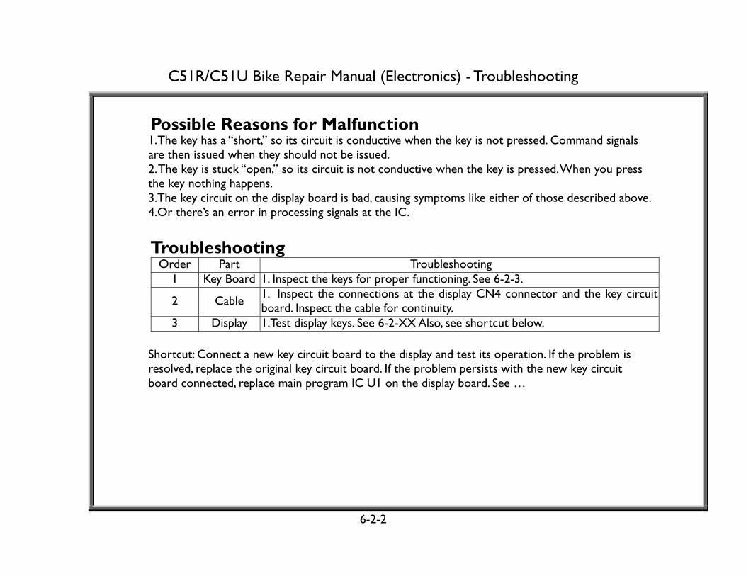
Possible Reasons for Malfunction
1. The key has a “short,” so its circuit is conductive when the key is not pressed. Command signals are then issued when they should not be issued. 2. The key is stuck “open,” so its circuit is not conductive when the key is pressed. When you press the key nothing happens. 3.The key circuit on the display board is bad, causing symptoms like either of those described above. 4.Or there’s an error in processing signals at the IC.
Troubleshooting
Order Part Troubleshooting 1 Key Board 1. Inspect the keys for proper functioning. See 6-2-3.
2 Cable 1. Inspect the connections at the display CN4 connector and the key circuit board. Inspect the cable for continuity.
3 Display 1.Test display keys. See 6-2-XX Also, see shortcut below.
Shortcut: Connect a new key circuit board to the display and test its operation. If the problem is resolved, replace the original key circuit board. If the problem persists with the new key circuit board connected, replace main program IC U1 on the display board. See …
6-2-2
C51R/C51U Bike Repair Manual (Electronics) - Troubleshooting
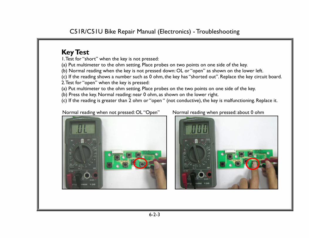
Key Test 1. Test for “short” when the key is not pressed: (a) Put multimeter to the ohm setting. Place probes on two points on one side of the key. (b) Normal reading when the key is not pressed down: OL or “open” as shown on the lower left. (c) If the reading shows a number such as 0 ohm, the key has “shorted out”. Replace the key circuit board. 2. Test for “open” when the key is pressed: (a) Put multimeter to the ohm setting. Place probes on the two points on one side of the key. (b) Press the key. Normal reading: near 0 ohm, as shown on the lower right. (c) If the reading is greater than 2 ohm or “open “ (not conductive), the key is malfunctioning. Replace it.
Normal reading when not pressed: OL “Open” Normal reading when pressed: about 0 ohm
6-2-3

C51R/C51U Bike Repair Manual (Electronics) - Troubleshooting
Display Board Connectors and IC
6-2-4
Notes: When a key activates even though it has not been pressed, disconnect connector CN4 from the display board. If the problem desists and the cable is good, the key is at fault. Replace the key circuit board. If a key is pressed but the display shows no reaction, inspect the following: The cable connection (left); cable continuity; the key (6-2-3). If replacing the key circuit board and its cable fails to resolve the problem, replace IC U1 on the display.
CN4 Connector (top) Key Board Cable (middle) Key Circuit Board (bottom)
U1 Main Program IC

SPORTS ART INDUSTRIAL CO., LTD.
Display Board Key Test 1. Test for “short” when the key is not pressed: (a) Put multimeter to the ohm setting. Place probes on two points on one side of the key as shown. (b) Normal reading when the key is not pressed down: OL or “open” as shown on the lower left. (c) If the reading shows a number near 0 ohm, the key has “shorted out.” Replace the key or the whole display board. 2. Test for “open” when the key is pressed: (a) Put multimeter to the ohm setting. Place probes on two points on one side of the key. (b) Press the key as shown on the lower right. Normal reading: close to 0 ohm. (c) If the reading is greater than 2 ohm or “open, “ the key is malfunctioning. Replace the key or the whole display board.
Normal reading when not pressed: “OL” or “open” Normal reading when pressed: near 0 ohm
6-2-5

C51R/C51U Bike Repair Manual (Electronics) - Troubleshooting
Key Definition Illustrations
6-2-6
Mode
Manual
Hill
Random
Interval 1
Interval 2
Mode
Level Up
Enter
Start
Level Down
Stop Pause/Reset Quick Start
Display Board Key Circuit Board

C51R/C51U Bike Repair Manual (Electronics) - Troubleshooting
Malfunction: ERR 7 When either the display main IC does not detect resistance VR voltage or the voltage exceeds the range, ERR7 appears on the display. Operation Diagram
DISPLAY BOARD
DRIVE BOARD
VRSIGNAL
VR
CA
BLE
VR VOLTAGE
ERR7 Operation
Order Part Operation 1 Drive Board 1.The drive board provides 5 VDC power supply for VR operation.
2 VR
1.Resistance motor operation turns a variable resistor (VR) on the motor/VR assembly. 2.As the VR turns one way, voltage output increases. As it turns the other way, voltage output decreases. (Continued on the following page.)
6-3-1

C51R/C51U Bike Repair Manual (Electronics) - Troubleshooting
ERR7 Operation (Continued from 6-3-1)
Order Part Operation 3 Cable 1. VR output voltage travels the cable to the drive board. 4 Drive Board 1.The drive board relays the VR voltage to the display. 5 Data Cable 1. VR output voltage travels the data cable from the drive board to the display.
6 Display Board
1.The main program IC detects the VR voltage. VR voltage corresponds to motor position. Motor movement changes the location of magnets inside the flywheel, which changes resistance. If there is no VR voltage or if the VR voltage exceeds the range, the display lacks information to command motor action, so ERR7 appears.
Circumstance of Malfunction 1. Turn on unit power. Display shows “ERR7”.
ERR7 Troubleshooting Order Part Procedure
1 Drive Board 1. Measure power supply to the VR across the black and blue wires. Normal reading: 5 VDC. If not, inspect the drive board. See 6-1-1. Replace it if receiving but not outputting power.
2 VR 1. Measure VR output across the white and blue wires to the drive board. Normal reading: 0.4-4.6 VDC. See 6-3-3. If not within this range, replace the motor/VR assembly.
3 Data Cable 1.Inspect the data cable and its connections on the drive board and the display board and at the hub board on C51R. Also, make sure that VR wires are in place properly.
4 Display Board 1. Inspect whether the main program IC U1 is in place properly. See 6-2-4.
6-3-2

C51R/C51U Bike Repair Manual (Electronics) - Troubleshooting
VR Output Voltage at the Drive Board Test Configuration
6-3-3

C51R/C51U Bike Repair Manual (Electronics) - Troubleshooting
VR Output Test Procedure 1. Put multimeter to the 20 VDC voltage setting. Place probes on the VR connector, CN4, white and blue wires. 2. Turn on unit power. Normal voltage reading: 0.4 to 4.6 VDC.
3. Press the RESISTANCE LEVEL<▲> key until the LEVEL window shows 20. The actual resistance should be at its highest level. Normal VR voltage: 4.59~4.49 VDC.
4. Press the RESISTANCE LEVEL<▼> key until the LEVEL window shows 1. The actual resistance should be at its lowest level. Normal VR voltage: 0.41~0.31 VDC.
Troubleshooting 1. If VR voltage reading differs from those above, or if it changes suddenly during operation, the VR is unstable. Replace it.
6-3-4

C51R/C51U Bike Repair Manual (Electronics) - Troubleshooting
Malfunction: No Resistance Motor Movement When you press the Level Up or Down key, the motor does not move. Motor Operation Operation Diagram
Motor Troubleshooting Order Part Description
1 Display 1.If the key beeps when pressed, assume that the signal was sent.
2 Data Cable
1.Inspect the cable and connections. On C51R, inspect the hub board connections. If issue occurred just after installation, inspect cable connections in the pedestal.
3 Drive Board
1.Inspect drive board power output to the motor. See 6-4-2. If there is power to the motor, but the motor does not operate, replace it. If there is no power output, inspect whether the drive board has power. See 6-1-1.
6-4-1
DISPLAY
DATA CABLE
MOTOR DRIVE BOARD
Order Part Description
1 Display 1.Key signal travels to the display. The main program IC then sends a command signal to the drive board.
2 Data Cable
1.The signal travels the data cable. On C51R, it also passes a hub board.
3 Drive Board
1.Drive board receives the signal and responds by putting out power to the motor. Level Up: +5 VDC; Level Down:-5 VDC.
Key Power: Signal:

C51R/C51U Bike Repair Manual (Electronics) - Troubleshooting
Motor Voltage Test Test Configuration
6-4-2

C51R/C51U Bike Repair Manual (Electronics) - Troubleshooting
Motor Voltage Test Procedure 1. Put multimeter to the 20 VDC setting. Place probes on the VR wires (brown and orange) on the drive board as shown on 6-4-2. 2.Turn on unit power. The display lights up.
3.Press RESISTANCE LEVEL<▲> key. Drive board LED3 lights up. Normal reading: +4.80~+5.20 VDC. Motor operates. Resistance increases.
4.Press RESISTANCE LEVEL<▼> key. Drive board LED4 lights up. Normal reading: -4.80~-5.20 VDC. Motor operates. Resistance decreases. 5.If there is no voltage, inspect the transformer output voltage. See 6-1-1. If the transformer voltage is OK, the drive board is bad. Replace it.
Motor Ohm Test Simply put, if there is power to the motor, and the motor does not operate, it is bad. But what happens if there is no power to the motor? Is there still a way to check the motor? Yes, you can perform an ohm test on the motor. Motors with very high or low ohm readings are bad. High ohm readings indicate too much impedance. Low readings, like 0 or 0.4, indicate an electrical “short,” and a reading of “OL” indicates an “open,” a break in the motor. Please see 6-4-4 for ohm test instructions.
6-4-3
C51R/C51U Bike Repair Manual (Electronics) - Troubleshooting
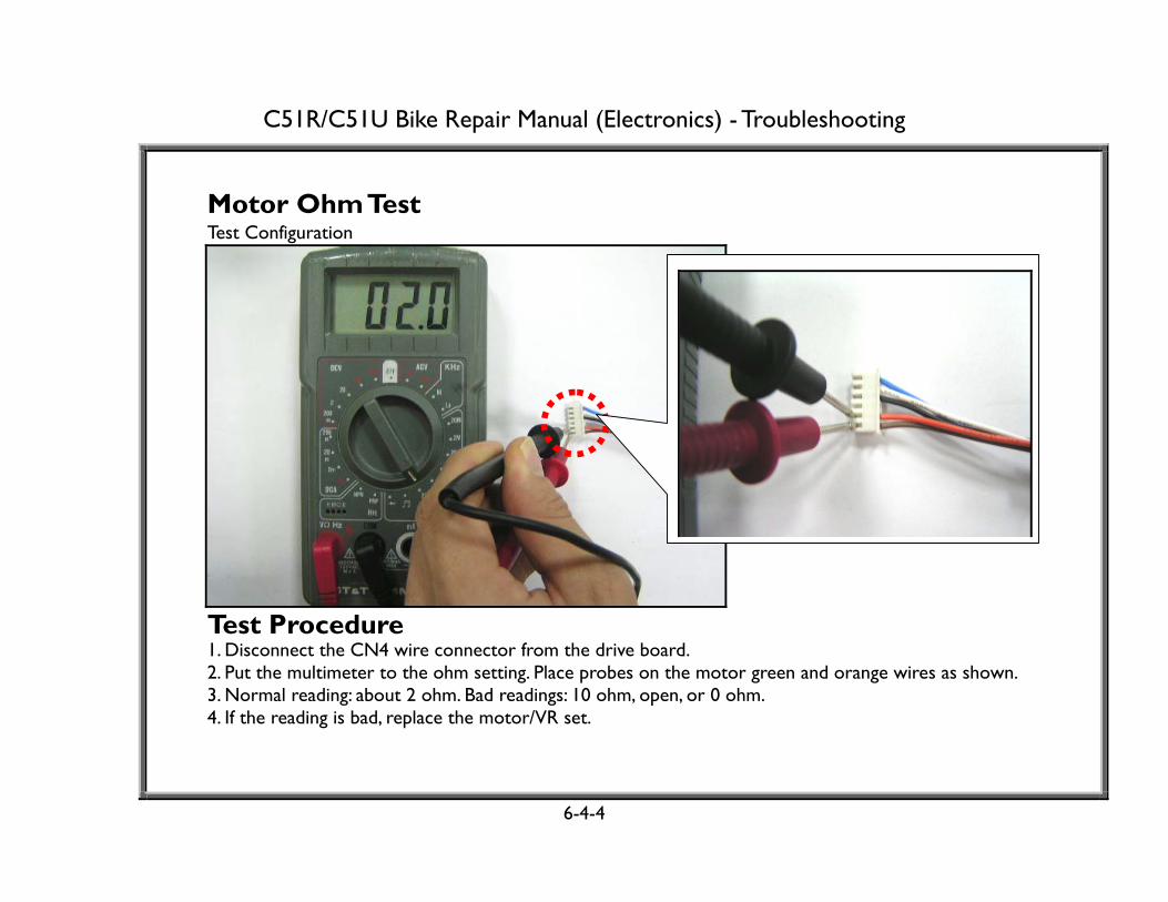
Motor Ohm Test Test Configuration
Test Procedure 1. Disconnect the CN4 wire connector from the drive board. 2. Put the multimeter to the ohm setting. Place probes on the motor green and orange wires as shown. 3. Normal reading: about 2 ohm. Bad readings: 10 ohm, open, or 0 ohm. 4. If the reading is bad, replace the motor/VR set.
6-4-4

C51R/C51U Bike Repair Manual (Electronics) - Troubleshooting
Malfunction: Polar Heart Rate Error The user puts on the Polar strap. But there is no Polar heart rate reading, or reading differs from the actual heart rate. Operation Diagram
Normal Operation Order Part Operation
1 Polar Transmitter 1. Heart rate transmitter detects the user’s pulse and transmits a signal to the Polar receiver.
2 Polar Receiver 1.The receiver receives the signal and sends it to the display board.
3 Display Board 1. The CPU reads the heart rate signal. 2.The heart rate appears in the heart rate window on the display.
6-5-1
DISPLAY BOARD
POLAR TRANSMITTER
POLAR RECEIVER
Heart Rate Signal Heart Rate Signal

C51R/C51U Bike Repair Manual (Electronics) - Troubleshooting
Possible Causes of Malfunction 1. Polar transmitter malfunction: No heart rate is detected or transmitted. 2. Polar receiver malfunction: The heart rate signal is not received. 3. Interference is disrupting POLAR receiver operation. 4.The Polar 3-pin wire is not connected properly. 5.The display board is defective; the CPU cannot detect or process the heart rate signal. Troubleshooting Order Part Troubleshooting
1 Polar Transmitter
1. Inspect whether the Polar transmitter operates on other products. See 6-5-3. 2. If not, replace it. Note: Transmitter batteries can be recharged by Polar.
2 Polar Receiver
1. Inspect Polar receiver placement. Location can determine signal reception. In general, keep it as far from electronic components as possible. 2. Inspect the solder on the Polar board. If solder is loose, replace the board. Make sure that nothing metal, including the serial number sticker, touches the antenna, the blue cube on the receiver board.
3 3-pin Cable 1. Inspect the connection of the 3-pin cable. Inspect cable continuity. 4 Display Board 1. Press down on the display board U1 IC to ensure a good connection.
6-5-2
C51R/C51U Bike Repair Manual (Electronics) - Troubleshooting
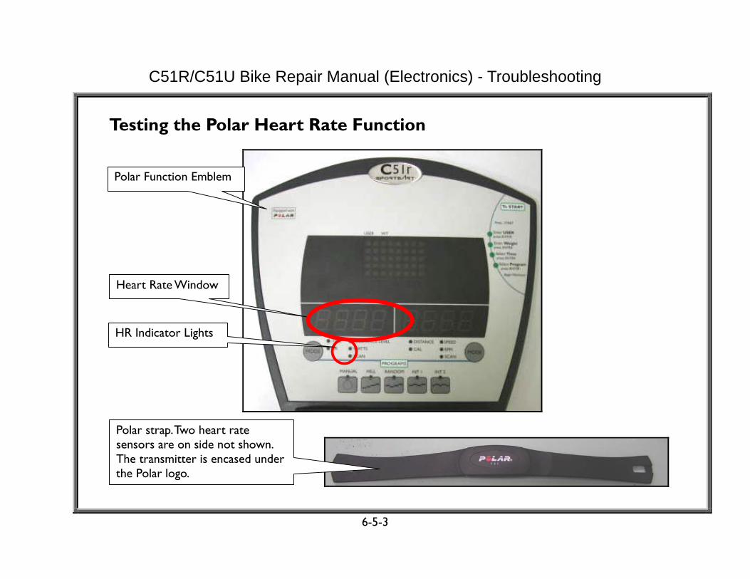
Testing the Polar Heart Rate Function
6-5-3
Heart Rate Window
Polar Function Emblem
Polar strap. Two heart rate sensors are on side not shown. The transmitter is encased under the Polar logo.
HR Indicator Lights

C51R/C51U Bike Repair Manual (Electronics) - Troubleshooting
Test Procedure 1. Put on the Polar strap, making sure it makes good contact with your skin. 2. Turn on unit power. Sit on the bike seat within 2 1/2 feet from the display. 3. Press the QUICK START key, then press the MODE (1) key until the HR LED lights. 4. The display should show your heart rate within five seconds.
Troubleshooting 1. Inspect whether the Polar strap works on other equipment. If it does not operate on any equipment, try another Polar strap. If it works on other equipment but not this unit, proceed to the following. 2. Inspect whether the wire from the Polar receiver board to the display is connected properly. 3. Replace the Polar receiver board. Re-insert the main program IC into its socket on the display board.
6-5-4

C51R/C51U Bike Repair Manual (Electronics) - Troubleshooting
Malfunction: Heart Touch Rate (HTR) Reading Error Hold onto the HTR handlebar. The display does not show any heart rate reading. Do not hold onto the HTR handlebar. The display shows a heart rate reading. Or, the heart rate reading is inaccurate.
Operation Diagram
DISPLAY BOARD HTR BOARD
HTRHANDLE-
BAR(RIGHT)
HEART RATESIGNAL
HTRHANDLE-BAR(LEFT)
6-6-1

C51R/C51U Bike Repair Manual (Electronics) - Troubleshooting
Normal Operation
Order Part Operation
1 HTR Handlebars
1.Hold onto the HTR handlebars with both hands. 2.Handlebars detect the user’s heart rate.
2 HTR Handlebar Wires
1.The left and right HTR handlebar wires transmit the heart rate to the heart rate board.
3 HTR Board
1.The heart rate board detects the HTR handlebar signal. 2.The heart rate board sends the heart rate signal to the display.
4 3-pin Cable 1.The signal from the heart rate board travels the 3-pin cable to the display.
5 Display Board 1.The display CPU detects the heart rate signal. 2.The display shows the heart rate value.
Possible Cause of Malfunction 1. HTR handlebars or wires are bad, making it impossible for the HTR board to receive a signal. 2. HTR board cannot read the heart rate signal. 3. The display CPU cannot detect the HTR signal.
6-6-2

C51R/C51U Bike Repair Manual (Electronics) - Troubleshooting
Troubleshooting Order Part Troubleshooting
1 HTR Handlebar
1. Clean the HTR handlebars. 2. Test the HTR cables.
2 HTR Cable
1. Inspect whether the HTR handlebar cable is broken or crimped. 2. Test the HTR wire.
3
HTR Board
1. Inspect the LEDs on the HTR board when the handlebars are held. 2. If LED2 does not light, inspect the HTR cable or handlebars. 3. If LED2 lights but LED3 does not flash, the issue is in the HTR board. 4. If LED2 lights and LED4 flashes, but LED5 does not flash (indicating no output), the HTR board is bad. 5. If you do not hold onto the handlebar but the HTR LED4 flashes, replace the HTR board.
4 3-pin Cable 1. Inspect wire connections from the HTR board to the display board. 5 Display Board 1. Inspect wire connections.
2. Inspect whether display IC U1 is installed properly.
6-6-3

C51R/C51U Bike Repair Manual (Electronics) - Troubleshooting
HTR Board Test HTR Board LED Placement and Definitions
LED Definitions LED Color Name Explanation LED1 Red POLAR Heart Rate Flashes to indicate incoming POLAR heart rate signal. LED2 Green HTR Handlebar Lights when someone holds the heart rate grips. LED3 Orange HTR Heart Rate Flashes when the HTR signal enters the HTR board. LED4 Red HTR Output Indicator Flashes when heart rate signal is output to the display.
6-6-4
LED1 LED2 LED3
LED4

C51R/C51U Bike Repair Manual (Electronics) - Troubleshooting
Test Procedure 1. When the HTR handlebars are not held, the HTR board LEDs do not light. 2. Hold the HTR handlebars with both hands; LED2 on the HTR board lights. 3. LED3 flashes to indicate that the HTR handlebar signal is entering the board. 4. LED4 flashes to indicate that the HTR board is sending a heart rate signal to the display board. 5. Within ten seconds, the heart rate value is displayed in the display PULSE window.
Troubleshooting If not as above, see the troubleshooting chart shown below.
Order Condition Cause of Malfunction Associated Parts
1 D3 does not light POLAR receiver has no heart rate input
POLAR transmitter, POLAR receiver, cables
2 D4 does not light HTR no one is holding the handlebar
HTR handlebar, Cable from handlebar to HTR board
3 D5 does not light No input from handlebars HTR handlebar, Cable from handlebar to HTR board
4 D6 does not light HTR board is not sending signal HTR board 5 Display does not
show a heart rate reading
HTR board signal is not sent to the display
3-pin cable, display board
6-6-5

C51R/C51U Bike Repair Manual (Electronics) - Troubleshooting
Testing the HTR Cable (5-pin cable to HTR handlebars) Test Procedure: 1. Do not turn on unit power. Disconnect the HTR board 5-pin cable connector. 2. Put multimeter to the 200 ohm setting or audible continuity setting. 3. Test the HTR wires for “shorts” and breaks by placing probes as indicated below.
Test Point Normal A-a Continuity B-b Continuity C-c Continuity D-d Continuity
Place the red probe on the wire. Place the black probe on the HTR grip plates.
(HTR board 5-pin cable)
Test Point Normal A-GND No Continuity B-GND No Continuity C-GND No Continuity D-GND No Continuity Frame - GND No Continuity
6-6-6
B
D
C
GND
d
b
c
a
A
Left Right

C51R/C51U Bike Repair Manual (Electronics) - Troubleshooting
Malfunction: Fuse Breaks 1. Turn on unit power. Display indicators do not light. Main fuse is broken. 2. Replace the fuse. Turn on unit power again. The fuse breaks again.
Operation Diagram
DISPLAY BOARD
DRIVE BOARD
FUSE
ON/OFFSWITCH
POWERCORD
6-7-1

C51R/C51U Bike Repair Manual (Electronics) - Troubleshooting
Fuse Holder Operation When the amp draw exceeds the fuse spec, the fuse breaks. Its breaking protects other components from damage. Drive board component failure is the most common cause of broken fuses. Possible Cause of Malfunction 1. Improper cable connections or shorts could cause high amp draw, making the drive board malfunction. 2. Drive board component failure causes the fuse to break as soon as the unit is turned on. 3. Other component failures might create high amp draw and cause the fuse to break.
Troubleshooting Inspect the fuse and fuse holder. Bad fuse holders have been known to cause fuses to fail. Disconnect the wire from the fuse to the drive board. Put in a good fuse. Turn on the unit. If the fuse does not break, replace the drive board if all wire connections out of the drive board are normal. If the fuse breaks, replace the fuse holder. If it breaks again even with the new fuse and fuse holder, replace the on/off switch.
6-7-2

C51R/C51U Bike Repair Manual (Electronics) - Troubleshooting
Malfunction: No Speed Count When you pedal on the bike, the speed does not appear on the display. Speed Count Operation Operation Diagram
6-8-1
DISPLAY
DATA CABLE
REED SWITCH
DRIVE BOARD
Order Part Description 1 Flywheel Pedal on the bike. The flywheel rotates.
2 Reed Switch
When a magnet on the flywheel passes a reed switch, the reed switch closes, completing the circuit.
3 Drive Board
The reed switch signal travels to the drive board. LED5 flashes. The drive board sends the signal up the data cable to the display.
4 Display Board
The display receives the signal and its main IC calculates the speed. Speed value appears.
Key Power: Signal:

C51R/C51U Bike Repair Manual (Electronics) - Troubleshooting
No Speed Count Troubleshooting Order Part Description
1 Drive Board
LED 5 should flash every time the reed switch passes the magnet. If not, inspect the following. See 5-2-2.
2 Cable Inspect the reed switch cable for continuity. Inspect connections.
3 Reed Switch
Set the multimeter to audible continuity. Place probes on the ends of both reed switch wires. Spin the flywheel. When the magnet passes the reed switch, the reed switch should activate (a click sound can be heard), the multimeter should beep, indicating continuity. If not, replace the reed switch. (Confirm that the magnet attracts metal and the attractive side faces the reed switch.)
4 Data Cable
Inspect the cable and connections. On C51R, inspect the hub board connections. If issue occurred just after installation, inspect cable connections in the pedestal.
5 Display Board
Inspect the main IC for proper connection. See 6-2-4.
6-8-2