ca bayonet / vg95234 connectors - itt cannon...vg95234 connectors are designed for single wire...
TRANSCRIPT

CA Bayonet / VG95234 Connectors

2 www.ittcannon.com
Dimensions shown in mm Specifications and dimensions subject to change
Proven Quality, Reliability & Expertise
ITT’s Interconnect Solutions’ Cannon brand is a leading global manufacturer of connector products serving international customers in the aerospace and defense, medical, energy, transportation and industrial end markets.
Whether delivering critical specs to aircraft pilots, streaming data through communications satellites or giving expectant parents a first look at their unborn children, Cannon connects the world’s most important information to the people who need it.
In 2015, Cannon celebrated 100 years that helped make history. Cannon products were used in the first “talking” movies and helped transmit the first messages home from the moon. Today we proudly continue our legacy of innovating to connect the world and inspire the successes of the next century – because amazing things happen when great things connect.
About ITT ITT is a diversified leading manufacturer of highly engineered critical components and customized technology solutions for the energy, transportation and industrial markets. Building on its heritage of innovation, ITT partners with its customers to deliver enduring solutions to the key industries that underpin our modern way of life.
Founded in 1920, ITT is headquartered in White Plains, N.Y., with employees in more than 35 countries and sales in a total of approximately 125 countries. The company generated 2014 revenues of $2.7 billion. For more information, visit www.itt.com.

3www.ittcannon.com
Dimensions shown in mm Specifications and dimensions subject to change
Our connector portfolio remains the most extensive in the industry.Offering a reliable and cost effective range of interconnect solutions.
Medical
Oil & Gas
Commercial & Military Aerospace
Heavy Equipment
Rail
lndustrial / lnstrumentation
Defense Vehicles

4 www.ittcannon.com
Dimensions shown in mm Specifications and dimensions subject to change
Introduction to CAB/VG95234
Cannon CA Bayonet series was designed in accordance with the VG95234 specification. This versatile and highly reliable connector series is an improvement on the well established MIL-C-5015 series. CA-Bayonet has a proven “reverse bayonet” coupling design that offers exceptional vibration protection, by a simple 120° turn.
Initially designed for aircraft and airborne applications, these rugged connectors are used in the electrical equipment of various off-road vehicles, construction machinery, industrial devices, railroad and military vehicles.
Advantages – rugged shell design
– waterproof up to IP68, (10 meters / 35 feet or 1 bar for 16 h) and IP69k (water jet)
– environmental protection
– bayonet coupling for easy mating and unmating
– vibration proof
Cannon has the complete VG95234 program available and, in addition, many other types which exceed the requirements of VG95234 and MIL-C-5015.
Attention Metal shell connectors which may be accessed are not suitable for mains power.
Connector Design & Features Robust design - Rugged aluminium shell for most severe conditions
- Bayonet coupling with rigid stainless steel roller bolts for fast and reliable mating (min. 500 cycles)
- An audible sound and a colour-marked snap-in position ensure additional coupling security
Contact arrangements & accessories - Over 140 arrangements and 12 connector sizes available for 1 to 65 circuits
- Wide selection of end bells for individual wires & jacketed cables
- Choice of accessories e.g. seals, gaskets, dust caps, wire hole fillers
VG & commercial offering - Connector offering according VG95234 standard – fully approved VG portfolio as required for military applications
- Extended offering of additional connector versions and endbell solutions for typical industrial applications
Contact offering - Contacts provide at least 500 mating cycles
- Contacts available as crimp, solder or PCB versions
- Gold plated contacts available for low current applications
- Crimp and assembly tooling available for all contact sizes
Environmental protection - Cadmium as standard, high performance plating 500h salt spray, highly conductive
- Cadmium & ChromVI free alternatives for RoHS applications
> ZnNi Blue grey A240 plating for 500h salt spray resistance and highly conductive
> ZnCo Black A232 plating, for 200h salt spray resistance, conductive
> ZnCo Green A233 plating, for 200h salt spray resistance and highly conductive
> ZnCo Black A239 plating, VG approved military plating, 48h salt spray and highly conductive
- IP67 pressure water & IP69k water jet sealing
Insulators / grommets
- Made of high quality polychloroprene for temperature range -55/125°C (-67/+257°F)
- Material is self-extinguishing
- Resistant against hydraulic fluids, jet fuel, diesel fuel, gasoline, lubricants, brake and fire extinguisher fluids

5www.ittcannon.com
Dimensions shown in mm Specifications and dimensions subject to change
Table of Contents
Proven Quality, Reliability & Expertise 2-3
Introduction to CAB/VG95234 4
VG/CA Bayonet Technical Data 6 Mechanical Features 7 Mounting Holes & Dimensions 8-9 How to Order 10-12 Contact Arrangements 13-26 Connector Dimensions 27-41 Coupling Dimensions 42
CAB IP69K General Information 43 How to Order 44 Connector Dimensions 45-46
Accessories 47-59
Tools 60-61
Part Number Search 62-64
Product Safety Information 65-67

6 www.ittcannon.com
Dimensions shown in mm Specifications and dimensions subject to change
Technical Data Contact rating at 20 °C (+68 °F) acc. to VG95234
Current rating Reference values based on measurements from a single pair of contacts.
Contact resistance (Mil li volt test) The contact resistance has to be tested according to VG95234 part 2, test no. 5.10.1 and VG 95210, part 37.
Insulation resistance Acc. to VG95319, part 2, test no. 5.12 and VG95210, part 32, test condition B
Standard insulator material > 1000 MΩ
FKM insulator material (upon request) > 5000 MΩ
Test voltage Acc. to VG95319, part 2, test no. 5.13 and VG 95210, part 31 Test voltage for service rating:
Operating voltage and connector usage Operating voltage for CA Bayonet / VG95234 connectors is limited to 50VAC / 75VDC according to the safety regulations defined in the European Low Voltage Directive (LVD) 2014/35/EU.
For other uses or regions please see appropriate regional regulations.
Air and creepage paths (min.)
Contact size Max. current A
10 8
16S/15S 22
16/15 22
12/25 41
8/60/100 74
4/160 135
0/500 245
Service rating Test voltage Vrms
In stru men ts 1050
A 2000
B 4500
D 2500
E 3500
Voltage class Instr. A D E
Air and creepage paths mm 0,7 1,1 2,8 4,8
Contact sizeMetric AWG
Max. contact resistance mΩ
10 – 12
15S/15 16S/16 6
25 12 3
60/100 8 1
160 4 0,5
500 0 0,2
VG/CA Bayonet
Derating Curves according to VG 95234
Ambient Temperature (OC)
Cur
rent
(A
)
200
20406080
100120140160180200220240
30 40 50 60 70 80 90 100 110 120 130
Contact size 500/0, wire size 50mm2/AWG0 Contact size 160/4, wire size 16mm2/AWG4 Contact size 60/100/8, wire size 60/100mm2/AWG8
Contact size 25/12, wire size 2,5mm2/AWG12 Contact size 15/15S/16/16S, wire size 1,5mm2/AWG16 Contact size 10/20, wire size 0,75/1,0mm2
Contact size 500, wire size 50mm2 Contact size 160, wire size 16mm2
Contact size 100, wire size 10mm2 Contact size 60, wire size 6mm2
Derating Curves - ITT Cannon
Ambient Temperature (OC)
Cur
rent
(A
)
200
20406080
100120140160180200220240260280300320
30 40 50 60 70 80 90 100 110 120 130

7www.ittcannon.com
Dimensions shown in mm Specifications and dimensions subject to change
Mechanical Features Ambient temperature Standard insulator material –55°/125°C (– 67/257°F)
FKM insulator material* –30°/200°C (– 22/392°F)
Safety provisions** In mated condition General (all connectors): IP67 acc. to ISO20653
VG 95234 Connectors: 1 bar for 16h
IP69K Version Connectors: Plug with Universal Endbell and receptacle with o-ring IP68 (1bar for 16h); IP69K (Jet water sealed) acc. to ISO20653
Vibration test 200 m/s2 at 10 to 2000 Hz
Mating cycles 500 min.
Withdrawal force per contact The corresponding separating force has to be measured according to VG95319, part 2, test no. 5.7. using the required test gage and DIN EN60512-16-5.
Materials Shell - Aluminum alloy Standard finishes
Cadmium (A66), VG approved,, 500h salt spray, highly conductive ZnCo black (A239) RoHS, VG approved, 48h salt spray, highly conductive ZnNi blue grey (A240) RoHS, 500h salt spray, highly conductive ZnCo black (A232) RoHS, 200h salt spray, conductive ZnCo green (A233) RoHS, 200h salt spray, highly conductive
Insulator and grommets Polychloroprene (Standard) FKM (High temperature)
Contacts - Copper alloy Standard finish - Hard silver Special finish - A176 nickel and hard gold plating
* consult factory for availability
** Longitudinal sealing: The connector is not sealed against fluids entering through the cable, as the sealing lips of the single wire sealing are pressing against the jacket of the individual conductors.
Only solutions as PG or ME adapters as well as universal endbell provide for longitudinal sealing provided that both ends of the cable are sealed correctly.
Coupling torque The allowable coupling torques have to be tested under full bundle conditions of the connectors to VG95319, part 2, test no. 5.8.2.
Contact retention The contact retention has to be tested according to VG95319, part 2, test no. 5.4. Test force direction = Mating direction.
Gauge (see also VG95234, Part 1)
Contact size AWG
Test force N
10 – 30
15S/15 16S/16 35
25 12 55
60/100 8 80
160 4 90
500 0 95
Gauge Contact diameter d +0,01
L–1
G 0,99 0,99 7
G 1,56 1,56 9
G 2,36 2,36 12
G 3,58 3,58 13
G 5,69 5,69 13
G 9,04 9,04 13
Shell Size Allowable coupling torque closing and opening Nm max.
Opening Nm min.
10SL 1,7 0,15
12S 2,5 0,23
14S 3,6 0,35
16S/16 5,5 0,46
18 8 0,58
20 9 0,7
22 11 0,8
24 14 0,8
28 17 0,92
32 19 1,03
36 23 1,03
Contact sizeMetric AWG
Separating force minN Gage
10 – 0,3 G 0,99
15S/15 16S/16 1,0 G 1,56
25 12 1,5 G 2,36
60/100 8 3,0 G 3,58
160 4 4,0 G 5,69
500 0 8,5 G 9,04

8 www.ittcannon.com
Dimensions shown in mm Specifications and dimensions subject to change
Mounting Holes Mounting holes for wall mounting receptacles style A, B1, B2, C1, C2, J1, J2, N1 and N2 acc. to VG95234, or CA 3100E/F/R-B and CA 3102 E-B.
Harnessing VG95234 connectors are designed for single wire harnessing.Full sealing will be guaranteed only by using wires in accordance with MIL-W-5086, LN 9251 (for AWG) and VG 95218-20 and TL 6145-011 (for metric wires). All other wires have to conform to wire and insulation diameters with the data given in the following table:
Wire Stripping Either mechanical or hot stripping can be used. Prevent conductor or insulator damage. For solder contacts, conductors have to be pretinned.
Note: Do not twist conductors used with crimp contacts. Do not touch uninsulated conductors before crimping. Twisting of conductors and grease or lubricants on the wires cause poor crimp quality.
When used with safety elements the max. outer diameter must not exceed the outer diameter of the screw head. *Drilling tolerances according to DIN ISO 286.
Shell size ø d1 (H12*)Style A Style B1, B2 CA 3102E-B C1, C2, J1, J2 N1, N2 CA 3100E, F, R-B
ø d2 (H13*) Style Style A, B2, C2, B1, C1, J1, N1 J2, N2 CA 3100E, F, R-B CA-B Mod-05
E ±0,15
Screws to be used A, B2, C2, J2, B1, C1, J1, N N2 CA 3100E, F CA-B-Mod. 05
10SL 16,4 18,5 3,4 4,5 18,2 M3...ISO 1580 M4...ISO 1207
12S 16,4 21,7 3,4 4,5 20,6 M3...ISO 1580 M4...ISO 1207
14S 19,7 24,9 3,4 4,5 23,0 M3...ISO 1580 M4...ISO 1207
16S 22,9 27,7 3,4 4,5 24,6 M3...ISO 1580 M4...ISO 1207
16 22,9 27,7 3,4 4,5 24,6 M3...ISO 1580 M4...ISO 1207
18 26,1 31,1 3,4 4,5 27,0 M3...ISO 1580 M4...ISO 1207
20 29,5 34,5 3,4 4,5 29,4 M3...ISO 1580 M4...ISO 1207
22 32,7 37,8 3,4 4,5 31,8 M3...ISO 1580 M4...ISO 1207
24 36,0 41,3 3,9 4,5 34,9 M3,5...ISO 1580 M4...ISO 1207
28 42,0 47,1 3,9 5,5 39,7 M3,5...ISO 1580 M5...ISO 1207
32 48,3 53,8 4,5 5,5 44,5 M4...ISO 1580 M5...ISO 1207
36 54,6 60,0 4,5 5,5 49,2 M4...ISO 1580 M5...ISO 1207
Contact size AWG Metric mm
Crimp- and solder contacts AWG Metric mm2
Insulation Ø AWG Metric mm
– 10 – 0,75-1,0 – 1,45-2,5
16S/16 15S/15 16 0,75-1,5 1,6-2,8 1,60-2,8
12 25 12 2,5 2,9-3,5 2,9-3,5
– 60 – 6,0 – 3,5-4,9
8 100 8 10,0 4,2-5,8 5,5-6,5
4 160 4 16,0 6,2-9,0 7,1-9,0
0 500 0 50,0 10,5-13,0 10,5-13,0
Contact size AWG Metric
Stripping length mm
– 10 4,0 + 0,4
16S/16 15S/15 6,0 + 0,5
12 25 6,0 + 0,5
8 60/100 11,0 + 0,8 – 0,4
4 160 11,0 + 0,8 – 0,4
0 500 13,0 + 0,8 – 0,4
9www.ittcannon.com
Dimensions shown in mm Specifications and dimensions subject to change
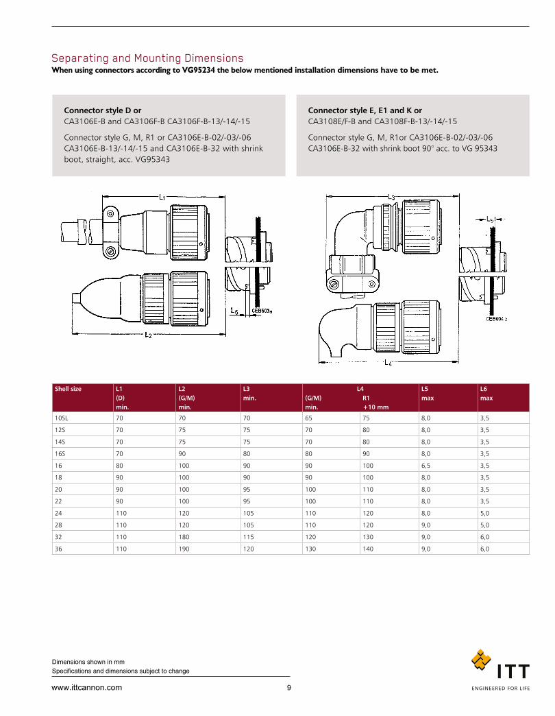
Separating and Mounting Dimensions When using connectors according to VG95234 the below mentioned installation dimensions have to be met.
Shell size L1 (D) min.
L2 (G/M) min.
L3 min.
L4 (G/M) R1 min. +10 mm
L5 max
L6 max
10SL 70 70 70 65 75 8,0 3,5
12S 70 75 75 70 80 8,0 3,5
14S 70 75 75 70 80 8,0 3,5
16S 70 90 80 80 90 8,0 3,5
16 80 100 90 90 100 6,5 3,5
18 90 100 90 90 100 8,0 3,5
20 90 100 95 100 110 8,0 3,5
22 90 100 95 100 110 8,0 3,5
24 110 120 105 110 120 8,0 5,0
28 110 120 105 110 120 9,0 5,0
32 110 180 115 120 130 9,0 6,0
36 110 190 120 130 140 9,0 6,0
Connector style D or CA3106E-B and CA3106F-B CA3106F-B-13/-14/-15
Connector style G, M, R1 or CA3106E-B-02/-03/-06 CA3106E-B-13/-14/-15 and CA3106E-B-32 with shrink boot, straight, acc. VG95343
Connector style D or CA3106E-B and CA3106F-B CA3106F-B-13/-14/-15
Connector style G, M, R1 or CA3106E-B-02/-03/-06 CA3106E-B-13/-14/-15 and CA3106E-B-32 with shrink boot, straight, acc. VG95343
Connector style D or CA3106E-B and CA3106F-B CA3106F-B-13/-14/-15
Connector style G, M, R1 or CA3106E-B-02/-03/-06 CA3106E-B-13/-14/-15 and CA3106E-B-32 with shrink boot, straight, acc. VG95343
Connector style E, E1 and K or CA3108E/F-B and CA3108F-B-13/-14/-15
Connector style G, M, R1or CA3106E-B-02/-03/-06 CA3106E-B-32 with shrink boot 90° acc. to VG 95343

10 www.ittcannon.com
Dimensions shown in mm Specifications and dimensions subject to change
Series
Shell style
Dash
Shell size
Contact arrangement
Contact type
Contact termination
Insulator position
With / without contacts
Plating
VG95234 A – S 132–6 N 1 H
How to order VG Order reference
Explanation Series VG95234
Shell style J1, J2, N1, N2, S1, U1, U2 – wall mounting receptacle F, V – cable connection receptacle A, B1, B2 – box mounting receptacle C1, C2 – bulkhead receptacle D, G, H, L, M, R1, T – straight plug E, E1, K – plug 90°
Shell size 10SL, 14S, 16S, 16, 18, 20, 22, 24, 28, 32 and 36
Contact arrangement See pages 13 to 26
Contact type P – Pin contact S – Socket contact
Contact termination Without identification = metric crimp contacts Identification ‘1’ = AWG crimp contacts Identification ‘2’ = mixed AWG and metric crimp contacts
Insulator position Positions N, X, Y allowed only, see details on ‘contact arrangement’ pages 13-23
With / without contacts Without identification = with crimp contacts Identification ‘1’ = without crimp contacts, to be ordered separately
Plating Without identification = cadmium Identification ‘H’ = RoHS, black, ZnCo plating, VG approved
* ‘H’ is the VG plating modification identical to commercial plating A239
Accessories acc. to VG Dummy receptacles VG95234 BOD Gaskets, front mount VG95234 DA Gaskets, rear mount VG95234 DH Protecting caps VG95234 KR Protecting caps VG95234 KB Cable clamps VG95234 KK Bushing VG95234 KT
Connector style D or CA3106E-B and CA3106F-B CA3106F-B-13/-14/-15
Connector style G, M, R1 or CA3106E-B-02/-03/-06 CA3106E-B-13/-14/-15 and CA3106E-B-32 with shrink boot, straight, acc. VG95343
Important! VG contact arrangements are restricted. Only those layouts listed in VG95234 standard are allowed. See the following pages for VG permitted layouts and contact arrangements.
Further details about contact terminations / wire ranges can be found on pages 54-59.

11www.ittcannon.com
Dimensions shown in mm Specifications and dimensions subject to change
Series
Shell style
Class
Shell size
Contact arrangement
Contact type
Insulator position
Connectors with bayonet coupling
Dash
Mo di fica tion
CA 3106 E 1 S18– X –B ***
How to order Cannon Order reference
Explanation Series CA – Circular connectors with bayonet coupling
Shell style 3100 – Wall mounting receptacle 3101 – Cable connecting receptacle 3102 – Box mounting receptacle 3105 – Dummy receptacle for front and panel mounting 3106 – Plug, straight 3108 – Plug, 90° TBF – Bulkhead receptacle
Class E – environmental with resilient insulators and endbell with clamp and bushing F – environmental with resilient insulator and endbell for flex tube R – environmental with resilient insulator and shortened light-weight endbell without cable clamp
Shell size 10SL, 12S, 14S, 16S, 16, 18, 20, 22, 24, 28, 32 and 36
Contact arrangement See pages 13 to 26
Contact type P – Pin S – Socket PS – one side pin, one side socket (only for TBF)
Insulator position Besides the normal position further insulator positions are possible for Cannon connectors (see page 13-23) to prevent mismating. Polarization is achieved by turning the pin contact insulator clockwise towards the shell, the socket insulator, however, in opposite clockwise direction. This information refers to the mating side of the contact insulator. For special insert alternations of standard inserts see page 24.
Modification see page 12
Connector style D or CA3106E-B and CA3106F-B CA3106F-B-13/-14/-15
Connector style G, M, R1 or CA3106E-B-02/-03/-06 CA3106E-B-13/-14/-15 and CA3106E-B-32 with shrink boot, straight, acc. VG95343

12 www.ittcannon.com
Dimensions shown in mm Specifications and dimensions subject to change
With Spring Washer and Friction Ring These connectors feature a spring washer and a friction ring under the coupling nut.
Advantage Improved resistance to vibration
How to order Delete “31” from standard part number and then insert “W” after Class E, F or R.
Example: CA06EW10SL-3P-B-14
The connectors acc. to VG95234 are generally delivered with spring washer.
Additional Connector Options CA3100E-B-02/03/06 Adapter for heat shrink boot
CA3100E-B-13/14/15 Adapter for shielded cables
CA02L-B Receptacle with PCB solder contacts
CA20L-B Rear mount receptacle with PCB solder contacts
CA06EH* H stands for High temperature FKM insulator and sealing material
CA07A-B Jam nut receptacle
CA00EP-B-TL* TINEL-LOCK adapter
CA06EW-B-TLXX* TINEL-LOCK adapter
CA06PG/ME PG or Metric gland adapter
*Consult factory for availability
Modifications (only for CA......-B) 01 – metric crimp contacts 02 – adapter for heat shrink boots AWG crimp contacts 03 – adapter for heat shrink boots, metric crimp contacts04 – rear mount, thread holes in flange, metric crimp
contacts (CA3102 only)05 – rear mount, through holes in flange, (CA3100, CA
3102, rear mounting CA 20, TBF)06 – adaptor for heat shrink boots, solder pot contacts08 – angular endbell, thread holes in flange (for CA3100 only)09 – angular endbell, through holes in flange (for CA3100
only)13 – shielded version, solder pot contacts14 – shielded version, metric crimp contacts15 – shielded version, AWG crimp contacts32 – shielded version, reduced cable entry diameter41 – grounding spring on barrel109 – F80 contacts, rear mount, thread holes in flange (for
CA3102 only)111 – rear mount, thread holes in flange (CA3102 only),
solder pot contactsF80 – AWG crimp contactsA176 – gold plated contact, see pages 54-55A232 – Zinc cobalt black platingA233 – Zinc cobalt green platingA239 – Zinc cobalt black plating, VG approved A240 – Zinc Nickel plating, blue grey platingF42 – less grommet and backshellF0 – less contacts, contacts to be ordered separately, see pages 54-55
Connector style D or CA3106E-B and CA3106F-B CA3106F-B-13/-14/-15
Connector style G, M, R1 or CA3106E-B-02/-03/-06 CA3106E-B-13/-14/-15 and CA3106E-B-32 with shrink boot, straight, acc. VG95343
Important! VG contact arrangements are restricted. Only those layouts listed in VG95234 standard are allowed. See the following pages for VG permitted layouts and contact arrangements.
Further details about contact terminations / wire ranges can be found on pages 54-59.

13www.ittcannon.com
Dimensions shown in mm Specifications and dimensions subject to change
Contact Arrangements
View on Mating face of Pin Insulator
No. of Contacts
Contact arrangement Contact size VG CA
Service rating
Insulator positionN V W X Y Z
Position Special polarization
Insulator (g) including contacts Pin Socket
3 10SL-3
15S
10SL-3
16S
A
0 – – – – – – – 6 9
2 10SL-4
15S
10SL-4
16S
A
0
–
–
–
–
–
–
–
4
6
♦ 2
–
12S-3
16S
A
0
100
70
145
215
290
–
–
4
6
1
–
12S-4
16S
D
0
–
–
–
–
–
–
–
3
4,5
4
–
12SA10
16S
Instr.
0
–
–
–
–
–
3
8
110
250
6
8
3
–
14S-1
16S
A
0
–
–
–
–
–
–
–
6
9
4
–
14S-2
16S
Instr.
0
–
–
120
240
–
–
–
7
11
1
–
14S-4
16S
D
0
–
–
–
–
–
–
–
4
7
5
–
14S-5
16S
Instr.
0
–
–
110
–
–
–
–
9
13
6 14S-6
15S
14S-6
16S
Instr.
0
–
–
–
–
–
–
–
11
15
♦ 3 14S-7
15S
14S-7
16S
A
0
–
90
180
270
–
–
6
9
2
–
14S-9
16S
Instr.
0
–
70
145
215
290
–
–
5
18
7
–
14SA7
16S
Instr.
0
–
–
–
–
–
–
–
10
15
♦ 7 16S-1
15S
16S-1
16S
A
0
–
80
–
–
280
–
–
4
19
2 16S-4
15S
16S-4
16S
D
0
–
35
110
250
325
–
–
7
10
♦ 3
–
16S-5
16S
A
0
–
70
145
215
290
–
–
8
12
5
–
16S-8
16S
A
0
–
–
170
265
–
–
–
10
15
♦ Attention: For all insert rotations, it is possible for miss-mating to occur. It is the responsibility of the customer to ensure they have selected correctly.

14 www.ittcannon.com
Dimensions shown in mm Specifications and dimensions subject to change
View on Mating face of Pin Insulator
No. of Contacts
Contact arrangement Contact size VG CA
Service rating
Insulator positionN V W X Y Z
Position Special polarization
Insulator (g) including contacts Pin Socket
3
2
1
16-7
15
100
16-7
16
8
A
0
–
80
110
250
280
–
–
16
25
4
2
2
–
16-9
12
16
A
0
–
35
110
250
325
–
–
13
20
♦ 3 16-10
25
16-10
12
A
0
–
90
180
270
–
–
–
17
24
2
–
16-11
12
A
0
–
35
110
250
325
–
–
11
17
1 16-12
160
16-12
4
A
0
–
–
–
–
–
–
–
24
28
2 16A11
25 (socket)
25A (pin) short
16A11
12
A
0
–
35
110
250
325
–
–
11
17
♦ 10 18-1
15
18-1
16
A (B, C,
F, G) Instr.
(all others)
0
–
70
145
215*
290
–
–
24
37
2
–
18-3
12
D
0
–
35
110
250
325
–
–
13
22
4
–
18-4
16
D
0
–
35
110
250
325
– –
19
30
3
2
1
–
18-5
12
16
D
0
–
80
110
250
280
–
–
15
25
1
–
18-6
4
D
0
–
–
–
–
–
– –
24
32
1
–
18-7
8
D
0
–
–
–
–
–
–
–
16
25
8
1
7
–
18-8
12
16
A
0
–
70
–
–
290
–
–
18
30
7
2
5
18-9
25
15
18-9
12
16
Instr.
0
–
80
110
250
280
–
–
18
30
4
–
18-10
12
A
0
–
–
120
240
–
–
–
13
22
5 18-11
25
18-11
12
A 0 – – 170 265 – – – 31 40
6 – 18-12
16
A 0 – 80 – – 280 – – 15 25
♦ Attention: For all insert rotations, it is possible for miss-mating to occur. It is the responsibility of the customer to ensure they have selected correctly.
Caution: This insulator rotation is not recommended as it can mate with normal rotation connectors.

15www.ittcannon.com
Dimensions shown in mm Specifications and dimensions subject to change
View on Mating face of Pin Insulator
No. of Contacts
Contact arrangement Contact size VG CA
Service rating
Insulator positionN V W X Y Z
Position Special polarization
Insulator (g) including contacts Pin Socket
♦ 4
1
3
18-13
60
25
18-13
8
12
A
0
–
80
110
250
280
–
–
15
24
7
2
5
–
18-17
12
16
Instr.
0
–
–
–
–
–
12
100
15
23
10 – 18-19
16
A 0 – – 120 240 – – – 19 31
5 – 18-20
16
A 0 – 90 180 270 – – 15 25
3 – 18-21
12
A 0 – – – – – – – 17 28
3 – 18-22
16
D 0 – 70 145 215 290 – – 10 20
1 20-2
500
20-2
0
D 0 – – – – – – – 46 55
3
–
20-3
12 D
0
–
70
145
215
290
–
–
28
42
4 – 20-4
12
D 0 – 45 110 250 – – 250
(20A37)
24 40
3 – 20-6
16
D 0 – – – – – – – 22 36
8
–
20-7
16
A (C, D, E,
F) D (A, B,
H, G)
0
–
80
110
250
280
–
–
28
42
6
2
4
20-8
100
15
20-8
8
16
In str.
0
–
80
110
250
280
–
–
37
49
13 – 20-11
16
In str. 0 – – – – – – – 25 41
5
3
2
– 20-14
12
8
A 0 – 80 110 250 280 – – 22 39
7 – 20-15
12
A 0 – 80 – – 280 – – 27 46
9
2
7
–
20-16
12
16
A
0
–
80
110
250
280
–
–
19
32
6
5
1
–
20-17
12
16
A
0
–
90
180
270
–
–
–
20
33
♦ Attention: For all insert rotations, it is possible for miss-mating to occur. It is the responsibility of the customer to ensure they have selected correctly.

16 www.ittcannon.com
Dimensions shown in mm Specifications and dimensions subject to change
View on Mating face of Pin Insulator
No. of Contacts
Contact arrangement Contact size VG CA
Service rating
Insulator positionN V W X Y Z
Position Special polarization
Insulator (g) including contacts Pin Socket
9
3
6
– 20-18
12
16
A
–
–
35
110
250
325
–
–
19 32
3 – 20-19
8
A 0 – 90 180 270 – – – 33 46
6
3
3
20-22
15
8
20-22
8
16
A
–
–
80♦ 110
♦ 250
280
–
–
37
49
2 – 20-23
8
A
–
–
35
110
250
325
–
–
25
35
4
2
2
– 20-24
8
16
A 0 – 35 110 250 325 – – 40 53
14 – 20-27
16
A 0 – 35 110 250 325 – – 26 42
17 – 20-29
16
A 0 – 80 – – 280 – – 29 47
11 – 20-33
16
A 0 – – – – 2
3
17
260
110
130
– 23 38
9 20A9
25
20A9
12
Instr.
(all others)
0
–
–
110
250
–
–
–
21
35
24 – 20A24
16
– 0 – – – – – – – 42 58
19 20A48
15
20A48
16
Instr. 0 – – 80 280 – – – 30 50
2 – 22-1
8
D 0 – 35 110 250 325 – – 28 42
3 22-2
8
22-2
8
D 0 – 70 145 215 290 – – 35 50
4
2
2
– 22-4
8
12
A
–
–
5
110
250
325
–
–
34
48
6
2
4
– 22-5
12
16
D
–
–
35
110
250
325
–
–
23
38
1 – 22-7
0
E
0
–
–
–
–
–
–
–
45
57
♦ Attention: For all insert rotations, it is possible for miss-mating to occur. It is the responsibility of the customer to ensure they have selected correctly.

17www.ittcannon.com
Dimensions shown in mm Specifications and dimensions subject to change
View on Mating face of Pin Insulator
No. of Contacts
Contact arrangement Contact size VG CA
Service rating
Insulator positionN V W X Y Z
Position Special polarization
Insulator (g) including contacts Pin Socket
2 – 22-8
12
E
–
–
35
110
250
325
–
–
18
28
3 – 22-9
12
E 0 – 70 145 215 290 – – 21 32
4 – 22-10
16
E
–
–
35
110
250
325
–
–
17
31
5
2
3
22-12
100
15
22-12
8
16
D 0 – 80 110 250 280 – – 28 42
♦ 19 22-14
15
22-14
16
A 0 – 80 – – 280 – – 30 50
6
5
1
– 22-15
12
16
A (A, B, C,
E, F) E (D)
0
–
80
110
250
280
–
–
30
50
9
3
– 22-16
12
16
A 0 – 80 110 250 280
–
–
–
28
45
14 – 22-19
16
A 0 – 80 110 250 280 – – 28 47
9
3
6
– 22-20
16
A 0 – 35 110 250 325 – – 22 39
3
2
1
– 22-21
16
0
A 0 – 80 110 250 280
–
–
–
49 58
4 22-22
100
22-22
8
A 0 – – 110 250 – – – 42 58
8 – 22-23
12
D (H)
A (all
others)
0
–
35
–
250
–
–
–
34
54
9
1
8
22-27
60
15
22-27
8
16
A (A to H)
0
–
80
–
250
280
–
–
21
34
7 – 22-28
12
A
–
–
80
–
–
280
–
–
33
50
4 22B22
60
– A 0 – – 110 250 –
–
–
42
58
7 – 24-2
12
D 0 – 80 – – 280 – – 33 53
♦ Attention: For all insert rotations, it is possible for miss-mating to occur. It is the responsibility of the customer to ensure they have selected correctly.

18 www.ittcannon.com
Dimensions shown in mm Specifications and dimensions subject to change
View on Mating face of Pin Insulator
No. of Contacts
Contact arrangement Contact size VG CA
Service rating
Insulator positionN V W X Y Z
Position Special polarization
Insulator (g) including contacts Pin Socket
4
1
3
–
24-4
0
16
D
–
–
80
110
250
280
–
–
51
63
16
–
24-5
16
A
–
–
80
110
250
280
–
–
30
54
16
2
14
–
24-7
12
16
A
0
–
80
110
250
280
–
–
45
65
2 24-9
4
24-9
4
A 0 – 35 110 250 325 – – 45 60
7 24-10
100
24-10
8
A 0 – 80 – – 280 – – 65 85
9
3
6
24-11
100/8
25/12
24-11
8
12
A
0
–
35
110
250
325
–
–
55
75
5
2
3
24-12
4
12
24-12
4
12
A
0
–
80
110
250
280
–
–
60
80
12 – 24-19
16
A 0 – – – – – – – 28 47
11
2
9
– 24-20
12
16
D
0
–
80
110
250
280
–
–
40
60
4 – 24-22
8
D 0 – 45 110 250 – – 44 61
7 – 24-27
16
E
–
–
80
–
–
280
–
–
21
37
24 24-28
15
24-28
16
Instr. 0 – 80 110 250 280 – – 40 65
12 – 24A24
12
A –
–
–
–
–
–
–
–
–
–
–
–
–
–
–
–
–
–
–
–
–
–
–
–
2
4
9
12
260
80
280
100
46 71
28
–
24A28
16
Instr.
–
–
65
146
235
–
–
–
42
75
19 13 5 1
24A51 16 12 8
A – – – – – – 14 30 60 70

19www.ittcannon.com
Dimensions shown in mm Specifications and dimensions subject to change
View on Mating face of Pin Insulator
No. of Contacts
Contact arrangement Contact size VG CA
Service rating
Insulator positionN V W X Y Z
Position Special polarization
Insulator (g) including contacts Pin Socket
14
12
2
– 28-2
16
12
D
–
–
35
110
250
325
–
–
43
61
5
2
2
1
– 28-5
4
16
12
D
–
–
35
110
250
325
–
–
60
70
12
6
6
–
28-9
16
12
D
–
–
80
110
250
280
–
–
46
65
7
2
2
3
– 28-10
4
8
12
A (= A, B,
C, D, E, F)
D (= G)
–
–
80
110
250
280
–
–
80
91
22
4
18
28-11
25
15
28-11
12
16
A
0
–
80
110
250
280
–
–
65
110
26 –
28-12
16
A
0
–
90
180
270
–
–
–
47
77
35 – 28-15
16
A 0 – 80 110 250 280 – – 54 90
20 – 28-16
16
A (A-L)
D (M, N,
P)
0
–
80
110
250
280
–
–
41
68
10
6
4
–
28-19
16
12
A (= C, E,
G, J, K, L)
D = A, B
B = H, M
–
–
80
110
250
280
–
–
40
58
14
10
4
28-20
25
15
28-20
12
16
A
0
–
80
110
250
280
–
–
65
110
37 28-21
15
28-21
16
A
0
–
80
110
250
280
–
–
58
93
6
3
3
28-22
160/4
15/16
28-22
4
16
D
0
–
70
145
215
290
–
–
80
120
All alternative insert position as above are permitted for VG95234 types.

20 www.ittcannon.com
Dimensions shown in mm Specifications and dimensions subject to change
View on Mating face of Pin Insulator
No. of Contacts
Contact arrangement Contact size VG CA
Service rating
Insulator positionN V W X Y Z
Position Special polarization
Insulator (g) including contacts Pin Socket
12
–
28-51
12
D
–
–
80
135
195
–
–
–
57
77
9
4
5
28A16
4
15
28A16
4
16
A (e)
Instr.
0
–
–
–
–
–
–
–
–
–
–
–
–
–
–
–
–
–
–
–
–
–
2
3
8
9
260
110
250
280
100
135
43 – 28A51
16
A 0
–
–
–
–
–
–
–
–
–
–
–
–
–
–
–
–
–
–
–
–
–
–
–
–
–
–
–
–
–
3
4
8
9
12
110
80
250
280
100
64 107
28
9
19
28A63
25
15
28A63
12
16
A
0
–
–
100
260
–
–
–
85
135
5
2
3
32-1
500/0
25/12
32-1
0
12
E (A)
D (all
others)
0
–
80
110
250
280
–
–
130
155
2
–
32-5
0
D
0
–
35
110
250
325
–
–
86
114
23
2
3
2
16
32-6
160/4
60/8
25/12
15/16
32-6
4
8
12
16
A
0
–
80
110
250
280
–
–
130
170
35
7
28
32-7
25
15
32-7
12
16
Instr.
(A, B, U, I.)
A (all
others)
0
–
80
125
235
280
–
–
110
160
30
6
24
– 32-8
12
16
A
0
–
80
125
235
280
–
–
105
155
14
12
2
–
32-9
16
4
D
0
–
80
110
250
280
–
–
79
130

21www.ittcannon.com
Dimensions shown in mm Specifications and dimensions subject to change
View on Mating face of Pin Insulator
No. of Contacts
Contact arrangement Contact size VG CA
Service rating
Insulator positionN V W X Y Z
Position Special polarization
Insulator (g) including contacts Pin Socket
23
5
18
–
32-13
12
16
D
0
–
80
110
250
280
–
–
95
145
8
2
6
32-15
0
25
32-15
0
12
D
0
–
35
110
250 325
–
–
140
165
4 – 32-17
4
D 0 – 45 110 250 – – – 80 116
54 – 32A10
16
A
–
–
–
–
–
–
–
–
–
–
–
80
–
–
–
–
110
–
–
–
–
250
–
–
–
–
280
–
–
–
3
4
8
9
12
110
80
250
280
100
89
132
47
–
32A47
16
–
A
–
–
–
–
–
–
–
–
–
–
–
–
–
–
–
–
–
–
–
–
–
–
–
–
–
–
–
–
–
–
–
–
–
–
–
–
2
3
4
8
9
12
260
110
80
250
280
100
73
120
5 – 32A55
16
A
–
–
80
110
250
280
–
–
90
134
61
20
41
32A69
15
10
32A69
16
20
Instr. 0 – – 110 250 – – – 49 84
Not for through-bulkhead receptacle C1 / C2. No solder pot contacts available for #10/20 contacts.
6
3
3
36-3
500/0
25/12
36-3
0
12
D
0
–
70
145
215
290
–
–
165
200
All alternative insert positions as above are permitted for VG95234 types.
4 36-5
500/0
36-5
0
A 0 – – 120 240 – – – 152 181

22 www.ittcannon.com
Dimensions shown in mm Specifications and dimensions subject to change
View on Mating face of Pin Insulator
No. of Contacts
Contact arrangement Contact size VG CA
Service rating
Insulator positionN V W X Y Z
Position Special polarization
Insulator (g) including contacts Pin Socket
6
4
2
36-6
4
0
36-6
4
0
A
0
–
35
110
250
25
–
–
155
173
47
7
40
– 36-7
12
16
A
–
–
80
110
250
280
–
–
92
144
47
1
46
– 36-8
12
16
A
–
–
80
110
250
280
–
–
80
132
31
14
14
2
1
– 36-9
16
12
8
4
A
0
–
80
125
235
280
–
–
116
159
48 36-10
15
36-10
16
A 0 – 80 125 235 280 – – 79 133
16
5
5
6
– 36-14
8
12
16
D
–
–
–
–
–
–
–
150
230
35 – 36-15
16
D (m)
A (all
others)
0
–
60
125
245
305
–
–
70
111
52 – 36A34
16
A
–
–
–
–
–
–
–
–
–
–
–
–
–
–
–
–
–
–
–
–
–
–
–
–
–
–
–
–
–
–
–
–
–
–
–
–
–
–
–
–
–
–
2
3
4
8
9
12
20
260
110
80
250
280
100
220
83
139

23www.ittcannon.com
Dimensions shown in mm Specifications and dimensions subject to change
View on Mating face of Pin Insulator
No. of Contacts
Contact arrangement Contact size VG CA
Service rating
Insulator positionN V W X Y Z
Position Special polarization
Insulator (g) including contacts Pin Socket
8
4
4
36A35
15
0
36A35
16
0
A
–
–
–
–
–
–
–
–
–
–
–
–
–
–
–
–
–
–
–
–
–
–
–
–
2
3
8
9
260
110
250
280
172
183
27 – 36A46
12
A
–
–
–
–
–
–
–
–
–
–
–
–
–
–
–
–
–
–
–
–
–
–
–
–
–
–
–
–
–
–
–
–
–
–
–
–
2
3
4
8
9
12
260
110
80
250
280
100
112
154
39
8
31
– 36A98
8
16
A
0
–
–
110
–
–
–
–
160
140
♦ 65
15
50
– 36A99
16
20*
Instr.
–
–
30
135
– –
–
–
80
121
No solder pot contacts available for #10/20 contacts.
♦ Attention: For all insert rotations, it is possible for miss-mating to occur. It is the responsibility of the customer to ensure they have selected correctly.
*Reduced contact termination 0,3 mm2.

24 www.ittcannon.com
Dimensions shown in mm Specifications and dimensions subject to change
Alternative Insert Positions Indicates location of centerline of key or keyway of shells in fixed normal position. Insert is rotated as shown by arrow and letters.
Connectors according to VG95234 are generally available with insert positions X and Y only.
Tolerances: # 10SL-20: ± 2°
# 22-36: ± 1,5°
# 32A69: ± 1°
Special Insert Positions A number of layouts allow for additional insert alternations. These special insert alternations are identified by a position number as shown in the table below.
Positions View shows mating side of pin or termination side of socket.
Insert positions are added without hyphen directly behind the contact type.
Example: CA3106F32A10P 2 -B-01
Position Polarization
2 260°
3 110°
4 80°
5 use pos. 3
6 85°
8 250°
9 280°
11 105°
12 100°
13 use pos. 8
14 30°
15 45°
16 120°
17 130°
18 150°
19 195°
20 220°
21 255°
22 290°
23 165°
24 330°
25 235°
26 125°
Pin Mating face
Normal position
Socket Mating face

25www.ittcannon.com
Dimensions shown in mm Specifications and dimensions subject to change
Contact Arrangements
Contact arrangement No. of Contacts
Contact size0 4 8 12 16 20 500 160 100 25 15 10 60
12S4 1 1
14S4 1 1
16-12 1 1
18-6 1 1
18-7 1 1
20-2 1 1
22-7 1 1
10SL4 2 2
14S9 2 2
16S4 2 2
16-11 2 2
16A11 2 2
18-3 2 2
20-23 2 2
22-1 2 2
22-8 2 2
24-9 2 2
32-5 2 2
10SL3 3 3
14S1 3 3
14S7 3 3
16S5 3 3
16-7 3 1 2
16-10 3 3
18-5 3 2 1
18-21 3 3
18-22 3 3
20-3 3 3
20-6 3 3
20-19 3 3
22-2 3 3
22-9 3 3
22-21 3 1 2
12SA10 4 4
14S2 4 4
16-9 4 2 2
18-4 4 4
18-10 4 4
18-13 4 1 3
20-4 4 4
20-24 4 2 2
22-4 4 2 2
22-10 4 4
22-22 4 4
22B22 4 4
24-4 4 1 3
24-22 4 4
32-17 4 4
36-5 4 4
Contact arrangement No. of Contacts
Contact size0 4 8 12 16 20 500 160 100 25 15 10 60
14S5 5 5
16S8 5 5
18-11 5 5
18-20 5 5
20-14 5 2 3
22-12 5 2 3
24-12 5 2 3
28-5 5 2 1 2
32-1 5 2 3
14S6 6 6
18-12 6 6
20-8 6 2 4
20-17 6 5 1
20-22 6 3 3
22-5 6 2 4
22-15 6 5 1
28-22 6 3 3
36-3 6 3 3
36-6 6 2 4
14SA7 7 7
16S1 7 7
18-9 7 2 5
18-17 7 2 5
20-15 7 7
22-28 7 7
24-2 7 7
24-10 7 7
24-27 7 7
28-10 7 2 2 3
18-8 8 1 7
20-7 8 8
22-23 8 8
32-15 8 2 6
36A35 8 4 4
24-6 8 8
20-16 9 2 7
20-18 9 3 6
20A9 9 9
22-16 9 3 6
22-20 9 9
22-27 9 1 8
24-11 9 3 6
28A16 9 4 5
18-1 10 10
18-19 10 10
28-19 10 4 6

26 www.ittcannon.com
Dimensions shown in mm Specifications and dimensions subject to change
Contact arrangement No. of Contacts
Contact size0 4 8 12 16 20 500 160 100 25 15 10 60
20-33 11 11
24-20 11 2 9
24-19 12 12
24A24 12 12
28-9 12 6 6
28-51 12 12
20-11 13 13
20-27 14 14
22-19 14 14
28-2 14 2 12
28-20 14 10 4
32-9 14 2 12
24-5 16 16
24-7 16 2 14
36-14 16 5 5 6
20-29 17 17
20A48 19 19
22-14 19 19
28-16 20 20
28-11 22 4 18
32-6 23 2 3 2 16
32-13 23 5 18
24-28 24 24
20A24 24 24
28-12 26 26
36A46 27 27
24A28 28 28
28A63 28 9 19
32-8 30 6 24
36-9 31 1 2 14 14
28-15 35 35
32-7 35 7 28
36-15 35 35
28-21 37 37
36A98 39 8 31
Contact arrangement No. of Contacts
Contact size0 4 8 12 16 20 500 160 100 25 15 10 60
28A51 43 43
32A47 47 47
36-7 47 7 40
36-8 47 1 46
36-10 48 48
36A34 52 52
32A10 54 54
32A55 55 55
32A69 61 20 41
36A99 65 15 50

27www.ittcannon.com
Dimensions shown in mm Specifications and dimensions subject to change
Box Mounting Receptacle - Front Mount
VG95234 Part no.
Can non Part no.
d1 max.
d2 H13*
d3 -0,15
l1 ±0,3
l2 ±0,4
l3 ±0,2
l4 ±0,3
Weight1) g max.
VG95234A-10SL-* CA3102E10SL-**-B 16,2 3,2 18,2 24,7 14,2 2,8 25,4 12
– CA3102E12S-**-B 16,2 3,2 21,4 24,7 14,2 3,2 28,0 15
VG95234A-14S-* CA3102E14S-**-B 19,2 3,2 24,6 24,7 14,2 3,2 30,0 17
VG95234A-16S-* CA3102E16S-**-B 22,4 3,2 27,4 24,7 14,2 3,2 32,5 19
VG95234A-16-* CA3102E16-**-B 22,4 3,2 27,4 33,8 19,0 3,2 32,5 22
VG95234A-18-* CA3102E18-**-B 25,6 3,2 30,8 33,8 19,0 4,0 35,0 28
VG95234A-20-* CA3102E20-**-B 29,0 3,2 34,2 33,8 19,0 4,0 38,0 33
VG95234A-22-* CA3102E22-**-B 32,2 3,2 37,4 33,8 19,0 4,0 41,0 38
VG95234A-24-* CA3102E24-**-B 35,3 3,7 40,9 33,8 20,6 4,0 44,5 46
VG95234A-28-* CA3102E28-**-B 41,4 3,7 46,7 33,8 20,6 4,0 50,8 52
VG95234A-32-* CA3102E32-**-B 47,8 4,3 53,4 33,8 22,2 4,0 57,0 64
VG95234A-36-* CA3102E36-**-B 52,6 4,3 59,6 33,8 22,2 4,0 63,5 80
VG95234 – Style A CA 3102E-B, additional modifications on page 12. Description: Receptacle for front panel mounting with square flange.
Threaded holes in flange not possible.
CA02L-B, additional modifications on page 12. Description: Receptacle for front panel mounting with solder pin contacts to solder into printed circuits. All pattern drawings upon request. For all other dimensions see above table. For contact arrangements with #16 and #12 contacts only. For#12 contacts consult factory.
1) Weight without insulator.
*Drilling tolerances according to DIN ISO 286.
28 www.ittcannon.com
Dimensions shown in mm Specifications and dimensions subject to change
VG95234 Part no.
Can non Part no.
d1 max.
d2
B1 H13*
B2 d3 -0,15
l1 ±0,3
l2 ±0,4
l3 ±0,2
l4 ±0,3
Weight1) g max.
VG95234BX-10SL-* CA3102E10SL-*B-*** 16,2 M4 3,2 18,2 24,7 18,2 2,8 25,4 14
– CA3102E12S-*B-*** 16,2 M4 3,2 21,4 24,7 18,2 3,2 28,0 18
VG95234BX-14S-* CA3102E14S-*B-*** 19,2 M4 3,2 24,6 24,7 18,2 3,2 30,0 21
CG95234BX-16S-* CA3102E16S-*B-*** 22,4 M4 3,2 27,4 24,7 18,2 3,2 32,5 22
VG95234BX-16-* CA3102E16-*B-*** 22,4 M4 3,2 27,4 33,8 23,05 3,2 32,5 27
VG95234BX-18-* CA3102E18-*B-*** 25,6 M4 3,2 30,8 33,8 23,05 4,0 35,0 33
VG95234BX-20-* CA3102E20-*B-*** 29,0 M4 3,2 34,2 33,8 23,05 4,0 38,0 37
VG95234BX-22-* CA3102E22-*B-*** 32,2 M4 3,2 37,4 33,8 23,05 4,0 41,0 42
VG95234BX-24-* CA3102E24-*B-*** 35,3 M4 3,7 40,9 33,8 23,05 4,0 44,5 48
VG95234BX-28-* CA3102E28-*B-*** 41,4 M5 3,7 46,7 33,8 24,05 4,0 50,8 58
VG95234BX-32-* CA3102E32-*B-*** 47,8 M5 4,3 53,4 33,8 24,05 4,0 57,0 72
VG95234BX-36-* CA3102E36-*B-*** 54,1 M5 4,3 59,6 33,8 24,05 4,0 63,5 84
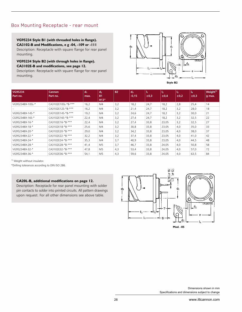
VG95234 Style B1 (with threaded holes in flange).CA3102-B and Modifications, e g -04, -109 or -111 Description: Receptacle with square flange for rear panel mounting.
VG95234 Style B2 (with through holes in flange).CA3102E-B and modifications, see page 12. Description: Receptacle with square flange for rear panel mounting.
CA20L-B, additional modifications on page 12. Description: Receptacle for rear panel mounting with solder pin contacts to solder into printed circuits. All pattern drawings upon request. For all other dimensions see above table.
1) Weight without insulator.
*Drilling tolerances according to DIN ISO 286.
Style B2
Mod. -05
Box Mounting Receptacle - rear mount

29www.ittcannon.com
Dimensions shown in mm Specifications and dimensions subject to change
*Drilling tolerances according to DIN ISO 286
VG95234 Part no.
Can non Part no.
d2
C1
C2 H13* Ø
d2 -0,15
e ±0,1
l1 ±0,7
l2 ±0,3
l3 ±0,2
l4 ±0,3
Weight1) g max.
VG95234CX-10SL-* TBF10SL-*B-*** M4 3,2 18,2 18,2 37,5 14,2 2,8 25,4 17
– TBF12S-*B-*** M4 3,2 21,4 20,6 37,5 14,2 3,2 28,0 24
VG95234CX-14S-* TBF14S-*B-*** M4 3,2 24,6 23,0 37,5 14,2 3,2 30,0 29
CG95234CX-16S-* TBF16S-*B-*** M4 3,2 27,4 24,6 37,5 14,2 3,2 32,5 34
VG95234CX-16-* TBF16-*B-*** M4 3,2 27,4 24,6 51,4 19,0 3,2 32,5 41
VG95234CX-18-* TBF18-*B-*** M4 3,2 30,8 27,0 51,4 19,0 4,0 35,0 49
VG95234CX-20-* TBF20-*B-*** M4 3,2 34,2 29,4 51,4 19,0 4,0 38,0 56
VG95234CX-22-* TBF22-*B-*** M4 3,2 37,4 31,8 51,4 19,0 4,0 41,0 61
VG95234CX-24-* TBF24-*B-*** M4 3,7 40,9 34,9 51,4 20,6 4,0 44,5 65
VG95234CX-28-* TBF28-*B-*** M5 3,7 46,7 39,7 51,4 20,6 4,0 50,8 76
VG95234CX-32-* TBF32-*B-*** M5 4,3 53,4 44,5 51,4 22,2 4,0 57,0 92
VG95234CX-36-* TBF36-*B-*** M5 4,3 59,6 49,2 51,4 22,2 4,0 63,5 103
Style C2
Socket PinThru-Bulkhead Receptacle
VG95234 – Style C1 TBF-B, additional modifications on page 12. Description: Bulkhead receptacle with mounting flange - with threaded holes.
VG95234 – Style C2 TBF-B-05, additional modifications on page 12. Description: Bulkhead receptacle with mounting flange - with through holes.
VG95234 – Style D CA3106E–B, additional modifications on page 12. Description: Straight plug with endbell, cable clamp and telescoping bushing.
1) Weight without insulator, grommets and contacts. 2) For max. cable entry. 3) For contact insert 36-5P a support washer is included.
VG95234 Part no.
Can non Part no.
d1 max.
d22)
max.l1 max.
l2 max.
l3 max.
l4 max.
Weight1) g max.
VG95234D-10SL-* CA3106E10SL-**B-*** 22,8 6,5 115 55 22,7 22,7 30
– CA3106E12S-**B-*** 26,0 6,5 115 55 22,7 22,7 37
VG95234D-14S-* CA3106E14S-**B-*** 29,2 9,0 115 60 27,5 27,5 44
VG95234D-16S-* CA3106E16S-**B-*** 32,0 11,0 115 60 30,0 30,0 54
VG95234D-16-* CA3106E16-**B-*** 32,0 11,0 120 70 30,0 30,0 62
VG95234D-18-* CA3106E18-**B-*** 36,5 14,2 120 75 33,0 33,0 70
VG95234D-20-* CA3106E20-**B-*** 39,9 15,8 120 75 37,5 37,5 85
VG95234D-22-* CA3106E22-**B-*** 43,1 15,8 120 75 37,5 37,5 92
VG95234D-24-* CA3106E24-**B-*** 46,6 21,4 120 90 43,3 43,3 127
VG95234D-28-* CA3106E28-**B-*** 53,4 21,4 120 90 48,0 43,3 154
VG95234D-32-* CA3106E32-**B-*** 60,1 26,7 120 90 55,0 51,7 199
VG95234D-36-*3) CA3106E36-**B-*** 66,3 31,7 130 100 58,0 58,0 260
Straight Plug with cable clamp

30 www.ittcannon.com
Dimensions shown in mm Specifications and dimensions subject to change
VG95234 Part no.
Can non Part no.
d3-Thread
Style E1 CA3108F
d1 max.
d22)
max.l1 max.
l2 max. E
l3 max. E1 E
l4 max.
l5 Weight1) g E E1
VG95234EX-10SL-* CA3108X10SL-**B-*** 5/8-24NEF-2A 22,8 6,5 45 42 30 100 22,7 9,4 37 27
– CA3108X12S-**B-*** 5/8-24NEF-2A 26,0 6,5 45 42 30 100 22,7 9,4 45 35
VG95234EX-14S-* CA3108X14S-**B-*** 3/4-20UN EF-2A 29,2 9,0 47 42 30 100 27,5 9,4 58 43
VG95234EX16S-* CA3108X16S-**B-*** 7/8-20UN EF-2A 32,0 11,0 48 45 30 100 30,0 9,4 68 48
VG95234EX-16-* CA3108X16-**B-*** 7/8-20UN EF-2A 32,0 11,0 57 45 30 100 30,0 9,4 78 58
VG95234EX-18-* CA3108X18-**B-*** 1-20UN EF-2A 36,5 14,2 58 53 35 100 33,0 9,4 90 58
VG95234EX-20-* CA3108X20-**B-*** 1 3/16-18UNEF-2A 39,9 15,8 61 53 35 100 37,5 9,4 109 74
VG95234EX-22-* CA3108X22-**B-*** 1 3/16-18UNEF-2A 43,1 15,8 61 53 35 100 37,5 9,4 113 78
VG95234EX-24-* CA3108X24-**B-*** 1 7/16-18UNEF-2A 46,6 21,4 66 58 40 100 43,3 9,4 159 104
VG95234EX-28-* CA3108X28-**B-*** 1 7/16-18UNEF-2A 53,4 21,4 66 58 40 100 43,3 9,4 181 126
VG95234EX-32-* CA3108X32-**B-*** 1 3/4 -18UNS-2A 60,1 26,7 72 66 45 110 51,7 11,0 245 160
VG95234EX-36-* CA3108 36-**B-*** 2 -18UNS-2A 66,3 31,7 75 69 50 110 58,0 12,6 300 190
Plug 90° with cable clamp or endbell for flex tube
Cable Connection Receptacle with cable clamp
VG95234 – Style E1 CA3108F-B, additional modifications on page 12. Description: Plug 90° with endbell for flex tube.
VG95234 – Style E CA3108E-B, additional modifications on page 12. Description: Plug 90° with cable clamp and telescoping bushing.
VG95234 – Style F CA3101E-B, additional modifications on page 12. Description: Cable connection receptacle with cable clamp and telescoping bushing.
1) Weight without insulator, grommets and contacts. 2) For max. cable entry. 3) For contact insert 36-5P a support washer is included.
VG95234 Part no.
Can non Part no.
d1 max.
d22) d3
-0,15l1 max.
l2 ±0,1
l3 ±0,2
l4 max.
l5 ±0,2
l7 max.
Weight1) g max.
VG95234F-10SL-* CA3101E10SL-**B-*** 25,2 6,5 18,2 57 18,2 2,8 120 20,6 22,7 35
– CA3101E12S-**B-*** 27,8 6,5 21,4 57 18,2 3,2 120 23,6 22,7 43
VG95234F-14S-* CA3101E14S-**B-*** 29,8 9,0 24,6 59 18,2 3,2 120 25,4 27,5 50
VG95234F-16S-* CA3101E16S-**B-*** 32,3 11,0 27,4 60 18,2 3,2 120 28,6 30,0 60
VG95234F-16-* CA3101E16-**B-*** 32,3 11,0 27,4 68 23,05 3,2 125 28,6 30,0 65
VG95234F-18-* CA3101E18-**B-*** 34,8 14,2 30,8 72 23,05 4,0 125 31,7 33,0 80
VG95234F-20-* CA3101E20-**B-*** 37,8 15,8 34,2 72 23,05 4,0 125 34,9 37,5 95
VG95234F-22-* CA3101E22-**B-*** 41,1 15,8 37,4 72 23,05 4,0 125 38,1 37,5 105
VG95234F-24-* CA3101E24-**B-*** 44,6 21,4 40,9 78 23,05 4,0 125 41,3 43,3 140
VG95234F-28-* CA3101E28-**B-*** 50,9 21,4 46,7 79 24,05 4,0 125 47,6 43,3 160
VG95234F-32-* CA3101E32-**B-*** 57,1 26,7 53,4 78 24,05 4,0 125 54,0 51,7 205
VG95234F-36*-*3) CA3101E36*)-**B-*** 63,6 31,7 59,6 78 24,05 4,0 135 60,6 58,0 270
VG/CA E1/F
VG E
31www.ittcannon.com
Dimensions shown in mm Specifications and dimensions subject to change
VG95234 Part no.
Can non Part no.
d1
max.d2 ±0,2
d3 ±0,2
d4
max.d4
min.l1 max.
l2±0,5
Weight1) g max.
VG95234G-10SL-* CA3106E10SL-**B-*** 22,8 17,0 15,5 13,3 7,7 50 11,7 24
– CA3106E12S-**B-*** 26,0 17,8 15,5 13,3 7,9 50 11,7 35
VG95234G-14S-* CA3106E14S-**B-*** 29,2 20,1 19,1 17,0 10,6 50 11,7 41
VG95234G-16S-* CA3106E16S-**B-*** 32,0 23,5 23,9 21,9 13,5 50 11,7 51
VG95234G-16-* CA3106E16-**B-*** 32,0 23,5 23,9 21,9 13,5 60 11,7 58
VG95234G-18-* CA3106E18-**B-*** 36,5 26,5 23,9 21,9 14,6 60 11,7 65
VG95234G-20-* CA3106E20-**B-*** 39,9 30,2 29,6 26,2 18,7 65 12,7 75
VG95234G-22-* CA3106E22-**B-*** 43,1 33,6 29,6 26,2 20,8 65 12,7 80
VG95234G-24-* CA3106E24-**B-*** 46,6 38,1 37,8 34,5 24,6 65 12,7 95
VG95234G-28-* CA3106E28-**B-*** 53,4 41,4 37,8 34,5 27,0 65 12,7 120
VG95234G-32-* CA3106E32-**B-*** 60,1 48,6 47,8 43,6 33,3 70 15,2 165
VG95234G-36-* CA3106E36-**B-*** 66,3 54,8 47,8 43,6 38,5 80 15,2 180
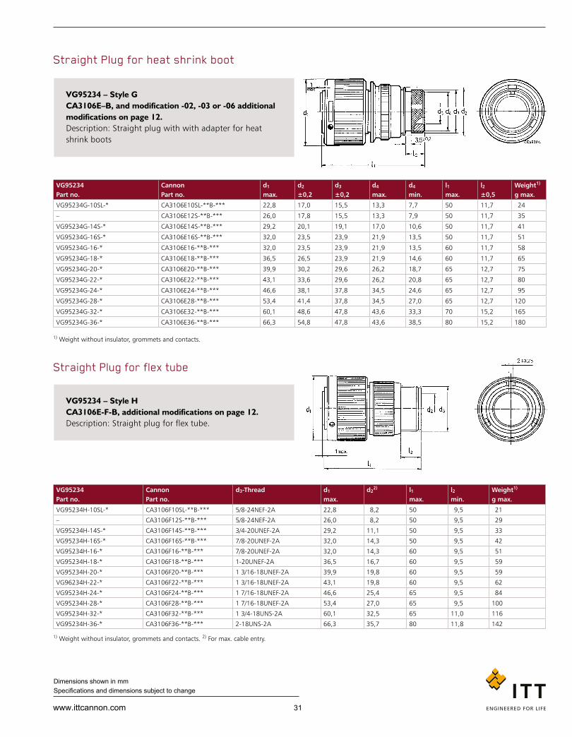
Straight Plug for heat shrink boot
VG95234 – Style G CA3106E–B, and modification -02, -03 or -06 additional modifications on page 12. Description: Straight plug with with adapter for heat shrink boots
1) Weight without insulator, grommets and contacts. 2) For max. cable entry.
1) Weight without insulator, grommets and contacts.
VG95234 Part no.
Can non Part no.
d3-Thread d1 max.
d22) l1
max.l2 min.
Weight1) g max.
VG95234H-10SL-* CA3106F10SL-**B-*** 5/8-24NEF-2A 22,8 8,2 50 9,5 21
– CA3106F12S-**B-*** 5/8-24NEF-2A 26,0 8,2 50 9,5 29
VG95234H-14S-* CA3106F14S-**B-*** 3/4-20UN EF-2A 29,2 11,1 50 9,5 33
VG95234H-16S-* CA3106F16S-**B-*** 7/8-20UN EF-2A 32,0 14,3 50 9,5 42
VG95234H-16-* CA3106F16-**B-*** 7/8-20UN EF-2A 32,0 14,3 60 9,5 51
VG95234H-18-* CA3106F18-**B-*** 1-20UN EF-2A 36,5 16,7 60 9,5 59
VG95234H-20-* CA3106F20-**B-*** 1 3/16-18UN EF-2A 39,9 19,8 60 9,5 59
VG96234H-22-* CA3106F22-**B-*** 1 3/16-18UNEF-2A 43,1 19,8 60 9,5 62
VG95234H-24-* CA3106F24-**B-*** 1 7/16-18UNEF-2A 46,6 25,4 65 9,5 84
VG95234H-28-* CA3106F28-**B-*** 1 7/16-18UNEF-2A 53,4 27,0 65 9,5 100
VG95234H-32-* CA3106F32-**B-*** 1 3/4-18UNS-2A 60,1 32,5 65 11,0 116
VG95234H-36-* CA3106F36-**B-*** 2-18UNS-2A 66,3 35,7 80 11,8 142
Straight Plug for flex tube
VG95234 – Style H CA3106E-F-B, additional modifications on page 12. Description: Straight plug for flex tube.

32 www.ittcannon.com
Dimensions shown in mm Specifications and dimensions subject to change
Wall Mounting Receptacle with cable clamp
Plug 90°, Shielded for flex tube
VG95234 – Style J1. CA3100E-B, additional modifications on page 12. Description: Wall mounting receptacle with cable clamp and telescope bushing, threaded holes in flange, for rear mounting.
VG95234 – Style J2. CA3100E-B, and modification -05, additional modifications on page 12. Description: Same as Style J1 but with through holes in flange, for rear mounting.
VG95234 – Style K. CA3108F, and modifications -13, -14 or -15, additional modifications on page 12. Description: Shielded plug with 90° endbell for flex tube, grounding spring on the barrel. No rear accessories to mount cable braid to the endbell.
VG95234 Part no.
Can non Part no.
d1 -0,15
d21) d3
J1 J2 H13*
l1 max.
l2 +0,4
l2 ±0,2
l4 ±0,3
l5 max.
VG95234*JX-10SL-* CA3100E10SL-**-B-*** 18,2 6,5 M4 3,2 57 18,2 2,8 25,4 120
– CA3100E12S-**-B-*** 21,4 6,5 M4 3,2 57 18,2 3,2 28,0 120
VG95234*JX-14S-* CA3100E14S-**-B-*** 24,6 9,0 M4 3,2 59 18,2 3,2 30,0 120
VG95234*JX-16S-* CA3100E16S-**-B-*** 27,4 11,0 M4 3,2 60 18,2 3,2 32,5 120
VG95234*JX-16-* CA3100E16-**-B-*** 27,4 11,0 M4 3,2 68 23,05 3,2 32,5 125
VG95234*JX-18-* CA3100E18-**-B-*** 30,8 14,2 M4 3,2 72 23,05 4,0 35,0 125
VG95234*JX-20-* CA3100E20-**-B-*** 34,2 15,8 M4 3,2 72 23,05 4,0 38,0 125
VG95234*JX-22-* CA3100E22-**-B-*** 37,4 15,8 M4 3,2 72 23,05 4,0 41,0 125
VG95234*JX-24-* CA3100E24-**-B-*** 40,9 21,4 M4 3,7 78 23,05 4,0 44,5 125
VG95234*JX-28-* CA3100E28-**-B-*** 46,7 21,4 M5 3,7 79 24,05 4,0 50,8 125
VG95234*JX-32-* CA3100E32-**-B-*** 53,4 26,7 M5 4,3 78 24,05 4,0 57,0 125
VG95234*JX-36-*2) CA3100E36-**-B-*** 59,6 31,7 M5 4,3 24,05 4,0 63,5 135 190
VG95234 Part no.
Can non Part no.
d3-Thread d1 max.
I1 max.
I2 max.
I3 min.
Weight1) g max.
CA3108F10SL-**-B-*** 5/8-24UN EF-2A 22,8 45 22 9,4 27
– CA3108F12S-**-B-*** 5/8-24UN EF-2A 26,0 45 22 9,4 35
VG95234K-14S-* CA3108F14S-**-B-*** 3/4-20UN EF-2A 29,2 47 24 9,4 43
VG95234K-16S-* CA3108F16S-**-B-*** 7/8-20UN EF-2A 32,0 48 25 9,4 48
VG95234K-16-* CA3108F16-**-B-*** 7/8-20UN EF-2A 32,0 57 25 9,4 58
VG95234K-18-* CA3108F18-**-B-*** 1-20UN EF-2A 36,5 58 27 9,4 58
VG95234K-20-* CA3108F20-**-B-*** 1 3/16-18UNEF-2A 39,9 61 29 9,4 74
VG95234K-22-* CA3108F22-**-B-*** 1 3/16-18UNEF-2A 43,1 61 30 9,4 78
VG95234K-24-* CA3108F24-**-B-*** 1 7/16-18UNEF-2A 46,6 66 32 9,4 104
VG95234K-28-* CA3108F28-**-B-*** 1 7/16-18UNEF-2A 53,4 66 34 9,4 126
CG95234K-32-* CA3108F32-**-B-*** 1 3/4-18UNS-2A 60,1 72 39,5 11,0 160
VG95234K-36-* CA3108F36-**-B-*** 2-18UNS-2A 66,3 75 45 12,6 190
1) For max. cable entry. 2) For contact insert 36-5P a support washer is included.
*Drilling tolerances according to DIN ISO 286
1) Weight without insulator, grommets and contacts.

33www.ittcannon.com
Dimensions shown in mm Specifications and dimensions subject to change
VG95234 Part no.
Can non Part no.
d1 max.
d22)
min.d3
±0,5d4
max.l1 max.
l2 +1
l3 ±0,5
Weight1) g max.
VG95234M-10SL-* CA3106E10SL-**-B-*** 22,8 7,7 18,5 16,3 55,0 17,0 7,0 40
– CA3106E12S-**-B-*** 26,0 9,3 20,0 17,0 55,0 17,0 7,0 42
VG95234M-14S-* CA3106E14S-**-B-*** 29,2 10,6 22,0 20,0 55,0 17,0 7,0 45
VG95234M-16S-* CA3106E16S-**-B-*** 32,0 13,5 25,0 23,0 60,0 18,0 8,0 55
VG95234M-16-* CA3106E16-**-B-*** 32,0 13,5 25,0 23,0 70,0 18,0 8,0 65
VG95234M-18-* CA3106E18-**-B-*** 36,5 14,6 28,0 24,5 70,0 18,0 8,0 75
VG95234M-20-* CA3106E20-**-B-*** 39,9 18,5 32,0 28,5 70,0 18,0 10,0 85
VG95234M-22-* CA3106E22-**-B-*** 43,1 20,8 34,0 30,5 70,0 18,0 10,0 100
VG95234M-24-* CA3106E24-**-B-*** 46,6 24,6 38,0 34,5 70,0 18,0 10,0 115
VG95234M-28-* CA3106E28-**-B-*** 53,4 27,0 41,0 37,5 70,0 18,0 10,0 130
VG95234M-32-* CA3106E32-**-B-*** 60,1 33,3 48,0 44,0 70,0 18,0 10,0 170
VG95234M-36-* CA3106E36-**-B-*** 66,3 38,5 55,0 51,0 80,0 18,0 10,0 190
VG95234 Part no.
Can non Part no.
d3-Thread d1 d22)
max.I1 I2
min.Weight1) g max.
– CA3106F10SL-**-B-*** 5/8-24UN EF-2A 22,8 8,2 50 9,5 21
– CA3106F12S-**-B-*** 5/8-24UN EF-2A 26,0 8,2 50 9,5 29
VG95234L-14S-* CA3106F14S-**-B-*** 3/4-20UN EF-2A 29,2 11,1 50 9,5 33
VG95234L-16S-* CA3106F16S-**-B-*** 7/8-20UN EF-2A 32,0 14,3 50 9,5 42
VG95234L-16-* CA3106F-16-**-B-*** 7/8-20UN EF-2A 32,0 14,3 60 9,5 51
VG95234L-18-* CA3106F-18-**-B-*** 1-20UN EF-2A 36,5 16,7 60 9,5 59
VG95234L-20-* CA3106F-20-**-B-*** 1 3/16-18UNEF-2A 39,9 19,8 60 9,5 58
VG95234L-22-* CA3106F-22-**-B-*** 1 3/16-18UNEF-2A 43,1 19,8 60 9,5 62
VG95234L-24-* CA3106F-24-**-B-*** 1 7/16-18UNEF-2A 46,6 25,4 65 9,5 84
VG95234L-28-* CA3106F-28-**-B-*** 1 7/16-18UNEF-2A 53,4 27,0 65 9,5 100
VG95234L-32-* CA3106F-32-**-B-*** 1 3/4-18UNS-2A 60,1 32,5 65 11,0 116
VG95234L-36-* CA3106F-36-**-B-*** 2-18UNS-2A 66,3 35,7 80 11,8 142
Straight Plug, shielded for flex tube
Straight Plug, shielded
VG95234 – Style L CA3106F-B, and modifications -13, -14 or -15, additional modifications on page 12. Description: Straight plug with endbell for flex tube, grounding spring on the barrel.
VG95234 – Style M CA3106E-B, and modifications -13, -14 or -15, additional modifications on page 12. Description: Straight, shielded plug with endbell for shielding braid, and heat shrink boots, grounding spring on the barrel.
1) Weight without insulator, grommets and contacts. 2) For max. cable entry.
1) Weight without insulator, grommets and contacts. 2) For max. cable entry.

34 www.ittcannon.com
Dimensions shown in mm Specifications and dimensions subject to change
VG95234 Part no.
Can non Part no.
d1 -0,15
d2 Thread H13*
N1 N2d3
±0,5d4
2)
min.d5
max.e ±0,1
l1 max.
l2 +0,4
l3 ±0,2
l4 +0,3
Weight1) g max.
VG95234*NX-10SL-* CA3100E10SL-**-B-*** 18,2 M4 3,2 18,5 7,7 16,3 18,2 55 18,2 2,8 25,4 45
VG95234*NX-14S-* CA3100E14S-**-B-*** 24,6 M4 3,2 22,0 10,6 20,0 23,0 58 18,2 3,2 30,0 55
VG95234*NX-16S-* CA3100E16S-**-B-*** 27,4 M4 3,2 25,0 13,5 23,0 24,6 70 18,2 3,2 32,5 65
VG95234*NX-16-* CA3100E16-**-B-*** 27,4 M4 3,2 25,0 13,5 23,0 24,6 70 23,05 3,2 32,5 75
VG95234*NX-18-* CA3100E18-**-B-*** 30,8 M4 3,2 28,0 14,6 24,5 27,0 70 23,05 4,0 35,0 85
VG95234*NX-20-* CA3100E20-**-B-*** 34,2 M4 3,2 32,0 18,5 28,5 29,4 70 23,05 4,0 38,4 95
VG95234*NX-22-* CA3100E22-**-B-*** 37,4 M4 3,2 34,0 20,8 30,5 31,8 70 23,05 4,0 41,0 105
VG95234*NX-24-* CA3100E24-**-B-*** 40,9 M4 3,7 38,0 24,6 34,5 34,9 70 23,05 4,0 44,5 120
VG95234*NX-28-* CA3100E28-**-B-*** 46,7 M5 3,7 41,0 27,0 37,5 39,7 70 24,05 4,0 50,8 150
VG95234*NX-32-* CA3100E32-**-B-*** 53,4 M5 4,3 48,0 33,3 44,0 44,5 75 24,05 4,0 57,0 190
VG95234*NX-36-* CA3100E36-**-B-*** 59,6 M5 4,3 55,0 38,5 51,0 49,2 85 24,05 4,0 63,5 220
/Mod.-05
Wall Mounting Receptacle, shielded
VG95234 – Style N1. CA3100E-B, and modifications -13, -14 or -15, see page 12. Description: Shielded receptacle with endbell for shielding braid, and heat shrink boots. With threaded holes in flange, for rear mounting.
VG95234 – Style N2. CA3100E-B, and modifications -05-13, -05-14 or -05-15, see page 12. Description: Same as Style N1 but with through holes in flange, for rear mounting.
VG95234 Part no.
Can non Part no.
d1 d3 d4 d5 d6 d7 l1 l2 Weight1) g max.
VG95234R1-14S CA3106E14S-**-B-32 29,2 10,0 14,0 M 20x1 21,0 23,5 57 21,0 50
VG95234R1-16S CA3106E16S-**-B-32 32,0 10,0 14,0 M 20x1 21,0 23,5 57 21,0 60
– CA3106E16S-**-B-32-D12 32,0 12,2 16,0 M 22x1 23,0 25,5 57 21,0 60
VG95234R1-18 CA3106E18-**-B-32 36,5 12,2 16,0 M 22x1 23,0 25,5 66 21,0 80
VG95234R1-20 CA3106E20-**-B-32 39,9 13,4 18,0 M 27x1 26,6 30,5 68 21,0 90
– CA3106E20-**-B-32-D19 39,9 19,6 22,6 M 27x1 31,5 35,5 68 21,0 90
VG95234R1-28 CA3106E28-**-B-32 53,4 19,0 26,0 M 35x1 37,6 41,5 76 26,0 135
– CA3106E28-**-B-32-D22 53,4 23,0 26,5 M 35x1 37,6 41,5 76 26,0 135
VG95234R1-32 CA3106E32-**-B-32 60,1 21,0 26,5 M 35x1 37,5 41,5 79 26,0 175
– CA3106E32-**-B-32-D22 60,3 23,0 26,5 M 35x1 37,5 41,5 82 26,0 200
– CA3106E36-**-B-32-D22 66,3 23,0 26,5 M 42x1 37,5 41,5 82 26,0 200
– CA3106E36-**-B-32-D26 66,3 27,0 33,0 M 42x1 45,0 49,7 82 26,0 200
Straight Plug, shielded
VG95234 – Style R1. CA3106E-B-32-DXX, see page 12. Description: Straight, shielded plug with endbell for system cable acc. MTV 6145-005. DXX means cable entry diameter, grounding spring on the barrel.
1) Weight without insulator, grommets and contacts. 2) For max. cable entry. *Drilling tolerances according to DIN ISO 286.
1) Weight without insulator, grommets and contacts.

35www.ittcannon.com
Dimensions shown in mm Specifications and dimensions subject to change
VG95234 Part no.
Can non Part no.
d1 -0,15
d2
Thread Ø H13*
d3 d4
±0,3d5 e
±0,1l1 max.
l2 ±0,4
l3 ±0,2
l4 ±0,3
l5 max.
VG95234S1-14S CA3100E14S-**-B-*** 24,6 M4 3,2 21,0 23,5 10,0 23,0 61 18,2 3,2 30,0 21,0
VG95234S1-16S CA3100E16S-**-B-*** 27,4 M4 3,2 21,0 23,5 10,0 24,6 61 18,2 3,2 32,5 21,0
VG95234S1-18 CA3100E18-**-B-*** 30,8 M4 3,2 23,0 25,5 12,2 27,0 70 23,05 4,0 35,0 21,0
VG95234S1-20 CA3100E20-**-B-*** 34,2 M4 3,2 26,6 30,5 13,4 29,4 72 23,05 4,0 38,0 21,0
VG95234S1-28 CA3100E28-**-B-*** 46,7 M5 3,7 37,5 41,5 19,0 39,7 78 24,05 4,0 50,8 26,0
VG95234S1-32 CA3100E32-**-B-*** 53,4 M5 4,3 37,5 41,5 21,0 44,5 81 24,05 4,0 57,0 26,0
/Mod.-05
Wall Mounting Receptacle, shielded
VG95234 – Style S1. CA3100E-B, and modifications -32, see page 12. Description: Wall mounting receptacle, shielded with endbell for system cable acc. MTV 6145-005, with threaded holes in flange, for rear mounting.
CA3100E-B, and modifications -32-05, see page 12. Description: Same as Style S1 but with through holes in flange, for rear mounting.
VG95234 Part no.
Can non Part no.
d1
max.d3
±0,2d3
±0,2d4
max.d5
min.l1
max.l2
±0,5Weight1) g max.
VG95234T-10SL-* CA3106E10SL-**B-*** 22,8 17,0 15,5 13,3 7,7 50 11,7 24
– CA3106E12S-**B-*** 26,0 17,8 15,5 13,3 7,9 50 11,7 35
VG95234T-14S-* CA3106E14S-**B-*** 29,2 20,1 19,1 17,0 10,6 50 11,7 41
VG95234T-16S-* CA3106E16S-**B-*** 32,0 23,5 23,9 21,9 13,5 50 11,7 51
VG95234T-16-* CA3106E16-**B-*** 32,0 23,5 23,9 21,9 13,5 60 11,7 58
VG95234T-18-* CA3106E18-**B-*** 36,5 26,5 23,9 21,9 14,6 60 11,7 65
VG95234T-20-* CA3106E20-**B-*** 39,9 30,2 29,6 26,2 18,7 65 12,7 75
VG95234T-22-* CA3106E22-**B-*** 43,1 33,6 29,6 26,2 20,8 65 12,7 80
VG95234T-24-* CA3106E24-**B-*** 46,6 38,1 37,8 34,5 24,6 65 12,7 95
VG95234T-28-* CA3106E28-**B-*** 53,4 41,4 37,8 34,5 27,0 65 12,7 120
VG95234T-32-* CA3106E32-**B-*** 60,1 48,6 47,8 43,6 33,3 70 15,2 165
VG95234T-36-* CA3106E36-**B-*** 66,3 54,8 47,8 43,6 38,5 80 15,2 180
Straight Plug, shielded with adapter for heat shrink boots
VG95234 – Style T. CA3106E-B-32-DXX, and modifications 02-41, 03-41 or 06-41, see page 12. Description: Straight plug, shielded ground spring on the barrel with endbell for heat shrink boot.
1) Weight without insulator, grommets and contacts.
*Drilling tolerances according to DIN ISO 286

36 www.ittcannon.com
Dimensions shown in mm Specifications and dimensions subject to change
VG95234 Part no.
Can non Part no.
d1 -0,15
d2
Thread Ø H13*
d3 ±0,2
d4 d5 max.
e ±0,1
l1 max.
l2 +0,4
l3 ±0,2
l4 +0,3
Weight1) g max.
VG95234UX-10SL-* CA3100E10SL-**-B-*** 18,2 M4 3,2 15,5 7,7 13,3 18,2 57 18,2 2,8 25,4 35
– CA3100E12S-**-B-*** 21,4 M4 3,2 15,5 7,9 13,3 20,6 57 18,2 3,2 28,0 45
VG95234UX-14S-* CA3100E14S-**-B-*** 24,6 M4 3,2 19,1 10,6 17,0 23,0 57 18,2 3,2 30,0 50
VG95234UX-16S-* CA3100E16S-**-B-*** 27,4 M4 3,2 23,9 13,5 21,9 24,6 57 18,2 3,2 32,5 60
VG95234UX-16-* CA3100E16-**-B-*** 27,4 M4 3,2 23,9 13,5 21,9 24,6 63 23,05 3,2 32,5 65
VG95234UX-18-* CA3100E18-**-B-*** 30,8 M4 3,2 23,9 14,6 21,9 27,0 65 23,05 4,0 35,0 80
VG95234UX-20-* CA3100E20-**-B-*** 34,2 M4 3,2 29,6 18,7 26,2 29,4 68 23,05 4,0 38,0 95
VG95234UX-22-* CA3100E22-**-B-*** 37,4 M4 3,2 29,6 20,8 26,2 31,8 68 23,05 4,0 41,0 105
VG95234UX-24-* CA3100E24-**-B-*** 40,9 M4 3,7 37,8 24,6 34,5 34,9 70 23,05 4,0 44,5 140
VG95234UX-28-* CA3100E28-**-B-*** 46,7 M5 3,7 37,8 27,0 34,5 39,7 71 24,05 4,0 50,8 160
VG95234UX-32-* CA3100E32-**-B-*** 53,4 M5 4,3 47,8 33,3 43,6 44,5 74 24,05 4,0 57,0 205
VG95234UX-36-* CA3100E36-**-B-*** 59,6 M5 4,3 47,8 38,5 43,6 49,2 74 24,05 4,0 63,5 270
Wall Mounting Receptacle for heat shrink boots
VG95234 – Style U1. CA3100E-B, and modifications -02, -03, or -06, see page 12 Description: Wall mounting receptacle with adapter for heat shrink boots, with threaded holes in flange, for rear mounting.
VG95234 – Style U2. CA3100E-B, and modifications -02-05, -03-05, -06-05, see page 12. Description: Same as Style U1 but with through holes in flange, for rear mounting.
VG95234 Part no.
Can non Part no.
d1 -0,15
d22)
min.d3 ±0,2
d4 max.
d5 max.
l1 max.
l2 +0,4
l3 ±0,2
l4 ±0,5
l5 Weight1) g max.
VG95234V-10SL-* CA3101E10SL-**-B-*** 18,2 7,7 15,5 25,2 13,3 57 18,2 2,8 11,7 20,6 35
CA3101E12S-**-B-*** 21,4 7,9 15,5 27,8 13,3 57 18,2 3,2 11,7 23,6 45
VG95234V-14S-* CA3101E14S-**-B-*** 24,6 10,6 19,1 29,8 17,0 57 18,2 3,2 11,7 25,4 50
VG95234V-16S-* CA3101E16S-**-B-*** 27,4 13,5 23,9 32,3 21,9 57 18,2 3,2 11,7 28,6 60
VG95234V-16-* CA3101E16-**-B-*** 27,4 13,5 23,9 32,3 21,9 63 23,05 3,2 11,5 28,6 65
VG95234V-18-* CA3101E18-**-B-*** 30,8 14,6 23,9 34,8 21,9 65 23,05 4,0 11,5 31,7 80
VG95234V-20-* CA3101E20-**-B-*** 34,2 18,7 29,6 37,8 26,2 68 23,05 4,0 12,7 34,9 95
VG95234V-22-* CA3101E22-**-B-*** 37,4 20,8 29,6 41,1 26,2 68 23,05 4,0 12,7 38,1 105
VG95234V-24-* CA3101E24-**-B-*** 40,9 24,6 37,8 44,6 34,5 70 23,05 4,0 12,7 41,3 140
VG95234V-28-* CA3101E28-**-B-*** 46,7 27,0 37,8 50,9 34,5 71 24,05 4,0 12,7 47,6 160
VG95234V-32-* CA3101E32-**-B-*** 53,4 33,3 47,8 57,1 43,6 74 24,05 4,0 15,2 54,0 205
VG95234V-36-* CA3101E36-**-B-*** 59,6 38,5 47,8 63,6 43,6 74 24,05 4,0 15,2 60,6 270
Cable Connection Receptacle for heat shrink boots
VG95234 – Style V. CA3101E-B, and modifications -02, -03 or -06, see page 12. Description: Cable connection receptacle with adapter for heat shrinkable boots.
1) Weight without insulator, grommets and contacts. *Drilling tolerances according to DIN ISO 286
1) Weight without insulator, grommets and contacts. 2) For max. cable entry.

37www.ittcannon.com
Dimensions shown in mm Specifications and dimensions subject to change
Can non Part no.
d1 -0,15
d2
Thread Ø H13*
d3
Threade ±0,1
I1
max.l2 +0,4
l3 ±0,2
l4 ±0,3
l5 min.
l6 max.
Weight1) g max.
CA3100F10SL-**-B-*** 18,2 M4 3,2 5/8-24UN EF-2A 18,2 50 18,2 2,8 25,4 9,4 30 47
CA3100F12S-**-B-*** 21,4 M4 3,2 5/8-24UN EF-2A 20,6 50 18,2 3,2 28,0 9,4 30 57
CA3100F14S-**-B-*** 24,6 M4 3,2 3/4-20UN EF-2A 23,0 52 18,2 3,2 30,0 9,4 30 57
CA3100F16S-**-B-*** 27,4 M4 3,2 7/8-20UN EF-2A 24,6 53 18,2 3,2 32,5 9,4 30 75
CA3100F16-**-B-*** 27,4 M4 3,2 7/8-20UN EF-2A 24,6 60 23,05 3,2 32,5 9,4 30 85
CA3100F18-**-B-*** 30,8 M4 3,2 1-20UN EF-2A 27,0 62 23,05 4,0 35,0 9,4 35 95
CA3100F20-**-B-*** 34,2 M4 3,2 1 3/16-18UNEF-2A 29,4 66 23,05 4,0 38,0 9,4 35 115
CA3100F22-**-B-*** 37,4 M4 3,2 1 3/16-18UNEF-2A 31,8 66 23,05 4,0 41,0 9,4 35 125
CA3100F24-**-B-*** 40,9 M4 3,7 1 7/16-18UNEF-2A 34,9 69 23,05 4,0 44,5 9,4 40 160
CA3100F28-**-B-*** 46,7 M5 3,7 1 7/16-18UNEF-2A 39,7 70 24,05 4,0 50,8 9,4 40 190
CA3100F32-**-B-*** 53,4 M5 4,3 1 3/4-18UNS-2A 44,5 74 24,05 4,0 57,0 11,0 45 250
CA3100F36-**-B-*** 59,6 M5 4,3 2-18UNS-2A 49,2 78 24,05 4,0 63,5 12,6 50 310
Can non Part no.
d1 -0,15
d2
Thread Ø H13*
d32)
max.e ±0,4
I1 max.
l2 +0,4
l3 ±0,2
l4 max.
l5 max.
l6 max.
l7 max.
Weight1) g max.
CA3100E10SL-**-B-*** 18,2 M4 3,2 6,5 18,2 50 18,2 2,8 25,4 42 22,7 100 50
CA3100E12S-**-B-*** 21,4 M4 3,2 6,5 20,6 50 18,2 3,2 28,0 42 22,7 100 60
CA3100E14S-**-B-*** 24,6 M4 3,2 9,0 23,0 52 18,2 3,2 30,0 42 27,5 100 70
CA3100E16S-**-B-*** 27,4 M4 3,2 11,0 24,6 53 18,2 3,2 32,5 45 30,0 100 80
CA3100E16-**-B-*** 27,4 M4 3,2 11,0 24,6 60 23,05 3,2 32,5 45 30,0 100 90
CA3100E18-**-B-*** 30,8 M4 3,2 14,2 27,0 62 23,05 4,0 35,0 53 33,0 100 100
CA3100E20-**-B-*** 34,2 M4 3,2 15,8 29,4 66 23,05 4,0 38,0 53 37,5 100 120
CA3100E22-**-B-*** 37,4 M4 3,2 15,8 31,8 66 23,05 4,0 41,0 53 37,5 100 130
CA3100E24-**-B-*** 40,9 M4 3,7 21,4 34,9 69 23,05 4,0 44,5 58 43,3 100 170
CA3100E28-**-B-*** 46,7 M5 3,7 21,4 39,7 70 24,05 4,0 50,8 58 43,3 100 200
CA3100E32-**-B-*** 53,4 M5 4,3 26,7 44,5 74 24,05 4,0 57,0 66 51,7 110 265
CA3100E36-**-B-*** 59,6 M5 4,3 31,7 49,2 78 24,05 4,0 63,5 69 58,0 110 325
Mod -09
1) Weight without insulator, grommets and contacts.
*Drilling tolerances according to DIN ISO 286.
Wall Mounting Receptacle, 90°, with cable clamp
CA3100E-B-08, additional modifications on page 12. Description: Wall mounting receptacle, with 90° endbell, cable clamp and telescoping bushing, flange with threaded holes.
CA3100E-B-09, additional modifications on page 12. Description: Wall mounting receptacle, with 90° endbell, cable clamp and telescoping bushing, flange with through holes.
Wall Mounting Receptacle, 90°, for flex tube
CA3100F-B-08, additional modifications on page 12. Description: Wall mounting receptacle, with 90° endbell for flex tube. Flange with threaded holes
CA3100F-B-09, additional modifications on page 12. Description: Wall mounting receptacle, with 90° endbell for flex tube. Flange with through holes.
1) Weight without insulator, grommets and contacts. 2) For max. cable entry. *Drilling tolerances according to DIN ISO 286

38 www.ittcannon.com
Dimensions shown in mm Specifications and dimensions subject to change
Can non Part no.
d1 -0,15
d2 Thread H13
d32)
max.d4
max.e ±0,1
l1
max.l2 +,0,4
l3
±0,2l4 ±0,3
Weight1) g max.
CA3100R10SL-**-B-*** 18,2 M4 3,2 9,6 22,0 18,2 50 18,2 2,8 25,4 40
CA3100R12S-**-B-*** 21,4 M4 3,2 10,3 23,0 20,6 52 18,2 3,2 28,0 50
CA3100R14S-**-B-*** 24,6 M4 3,2 12,4 27,0 23,0 52 18,2 3,2 30,0 60
CA3100R16S-**-B-*** 27,4 M4 3,2 15,4 28,0 24,6 58 18,2 3,2 32,5 70
CA3100R16-**-B-*** 27,4 M4 3,2 15,4 28,0 24,6 58 23,05 3,2 32,5 75
CA3100R18-**-B-*** 30,8 M4 3,2 18,4 31,0 27,0 65 23,05 4,0 35,0 90
CA3100R20-**-B-*** 34,2 M4 3,2 22,0 35,0 29,4 65 23,05 4,0 38,0 110
CA3100R22-**-B-*** 37,4 M4 3,2 24,7 38,0 31,8 65 23,05 4,0 41,0 125
CA3100R24-**-B-*** 40,9 M4 3,7 27,6 42,0 34,9 67 23,05 4,0 44,5 160
CA3100R28-**-B-*** 46,7 M5 3,7 31,6 49,0 39,7 67 24,05 4,0 50,8 190
CA3100R32-**-B-*** 53,4 M5 4,3 38,5 55,0 44,5 67 24,05 4,0 57,0 230
CA3100R36-**-B-*** 59,6 M5 4,3 44,5 62,0 49,2 67 24,05 4,0 63,5 300
Wall Mounting Receptacle with short endbell
Cable Connection Receptacle for flex tube
CA3100R-B, additional modifications on page 12. Description: Wall mounting receptacle with short endbell without cable clamp. Flange with threaded holes, for rear mounting.
CA3100R-B, additional modifications on page 12. Description: Wall mounting receptacle with short endbell without cable clamp. Flange with through holes, for rear mounting.
CA3101F-B, additional modifications on page 12. Description: Cable connection receptacle for flex tube.
1) Weight without insulator, grommets and contacts. 2) For max. cable entry.
1) Weight without insulator, grommets and contacts. 2) For max. cable entry.
*Drilling tolerances according to DIN ISO 286.
Can non Part no.
d1 -0,15
d22)
min.d3 Thread
d4 max.
l1 max.
l2 +0,4
l3 ±0,2
l4 min.
l5 ±0,2
Weight1) g max.
CA3101F10SL-**-B-*** 18,2 8,2 5/8-24NEF-2A 25,2 52 18,2 2,8 9,5 20,6 35
CA3101F12S-**-B-*** 21,4 8,2 5/8-24NEF-2A 27,8 52 18,2 3,2 9,5 23,6 45
CA3101F14S-**-B-*** 24,6 11,1 3/4-20UN EF-2A 29,8 52 18,2 3,2 9,5 25,4 50
CA3101F16S-**-B-*** 27,4 14,3 7/8-20UN EF-2A 32,3 59 18,2 3,2 9,5 28,6 60
CA3101F16-**-B-*** 27,4 14,3 7/8-20UN EF-2A 32,3 59 23,05 3,2 9,5 28,6 65
CA3101F18-**-B-*** 30,8 16,7 1-20UN EF-2A 34,8 63 23,05 4,0 9,5 31,7 80
CA3101F20-**-B-*** 34,2 19,8 1 3/16-18UNEF-2A 37,8 63 23,05 4,0 9,5 34,9 95
CA3101F22-**-B-*** 37,4 19,8 1 3/16-18UNEF-2A 41,1 66 23,05 4,0 9,5 38,1 105
CA3101F24-**-B-*** 40,9 25,4 1 7/16-18UNEF-2A 44,6 69 23,05 4,0 9,5 41,3 140
CA3101F28-**-B-*** 46,7 27,0 1 7/16-18UNEF-2A 50,9 70 24,05 4,0 9,5 47,6 160
CA3101F32-**-B-*** 53,4 32,5 1 3/4-16UNS-2A 57,1 71 24,05 4,0 11,0 54,0 205
CA3101F36-**-B-*** 59,6 35,7 2-18UNS-2A 63,6 73 24,05 4,0 11,8 60,6 270
Mod -05

39www.ittcannon.com
Dimensions shown in mm Specifications and dimensions subject to change
Can non Part no.
d1 -0,15
d2
Thread Ø H13*
d32)
d4
Threade ±0,1
l1 max.
l2 +0,4
l3 ±0,2
l4 ±0,3
l5 min.
Weight1) g max.
CA3100F10SL-**-B-*** 18,2 M4 3,2 8,2 5/8-24NEF-2A 18,2 52 18,2 2,8 25,4 9,5 40
CA3100F12S-**-B-*** 21,4 M4 3,2 8,2 5/8-24NEF-2A 20,6 52 18,2 3,2 28,0 9,5 50
CA3100F14S-**-B-*** 24,5 M4 3,2 11,1 3/4-20UN EF-2A 23,0 52 18,2 3,2 30,0 9,5 60
CA3100F16S-**-B-*** 27,4 M4 3,2 14,3 7/8-20UN EF-2A 24,6 59 18,2 3,2 32,5 9,5 70
CA3100F16-**-B-*** 27,4 M4 3,2 14,3 7/8-20UN EF-2A 24,6 59 23,05 3,2 32,5 9,5 75
CA3100F18-**-B-*** 30,8 M4 3,2 16,7 1-20UN EF-2A 27,0 63 23,05 4,0 35,0 9,5 90
CA3100F20-**-B-*** 34,2 M4 3,2 19,8 1 3/16-18UNEF-2A 29,4 63 23,05 4,0 38,0 9,5 110
CA3100F22-**-B-*** 37,4 M4 3,2 19,8 1 3/16-18UNEF-2A 31,8 66 23,05 4,0 42,0 9,5 125
CA3100F24-**-B-*** 40,9 M4 3,7 25,4 1 7/16-18UNEF-2A 34,9 69 23,05 4,0 44,5 9,5 160
CA3100F28-**-B-*** 46,7 M5 3,7 27,0 1 7/16-18UNEF-2A 39,7 70 24,05 4,0 50,8 9,5 190
CA3100F32-**-B-*** 53,4 M5 4,3 32,5 1 3/4-18UNS-2A 44,5 71 24,05 4,0 57,0 11,0 230
CA3100F36-**-B-*** 59,6 M5 4,3 35,7 2-18UNS-2A 49,2 73 24,05 4,0 63,5 11,8 300
Wall Mounting Receptacle for flex tube
CA3100F-B, additional modifications on page 12. Description: Wall mounting receptacle with straight endbell for flex tube. Flange with threaded holes, for rear mounting.
CA3100F-B-05, additional modifications on page 12. Description: Wall mounting receptacle with straight endbell for flex tube. Flange with through holes, for rear mounting.
1) Weight without insulator, grommets and contacts. 2) For max. cable entry.
*Drilling tolerances according to DIN ISO 286.
Mod -05

40 www.ittcannon.com
Dimensions shown in mm Specifications and dimensions subject to change
Can non Part no.
d1 -0,15
d2 min.
d3
max.d4 max.
l1
max.l2 +,0,4
l3
±0,2l5 ±0,2
Weight1) g max.
CA3101R10SL-**-B-*** 18,2 9,6 22,0 25,2 50 18,2 2,8 20,6 32
CA3101R12S-**-B-*** 21,4 10,3 23,0 27,8 52 18,2 3,2 23,6 40
CA3101R14S-**-B-*** 24,6 12,4 27,0 29,8 52 18,2 3,2 25,4 47
CA3101R16S-**-B-*** 27,4 15,4 28,0 32,3 58 18,2 3,2 28,6 55
CA3101R16-**-B-*** 27,4 15,4 28,0 32,3 58 23,05 3,2 28,6 60
CA3101R18-**-B-*** 30,8 18,4 31,0 34,8 65 23,05 4,0 31,7 75
CA3101R20-**-B-*** 34,2 22,0 35,0 37,8 65 23,05 4,0 34,9 90
CA3101R22-**-B-*** 37,4 24,7 38,0 41,1 65 23,05 4,0 38,1 100
CA3101R24-**-B-*** 40,9 27,6 42,0 44,6 67 23,05 4,0 41,3 135
CA3101R28-**-B-*** 46,7 31,6 49,0 50,9 67 24,05 4,0 47,6 155
CA3101R32-**-B-*** 53,4 38,5 55,0 57,1 67 24,05 4,0 54,0 200
CA3101R36-**-B-*** 59,6 44,5 62,0 63,6 67 24,05 4,0 60,6 260
Cable Connection Receptacle with short endbell
Straight Plug with short endbell
CA3101R-B, additional modifications on page 12. Description: Cable connection receptacle with short endbell, without cable clamp.
CA3106R-B, additional modifications on page 12. Description: Straight plug with short endbell, without cable clamp.
Can non Part no.
d1 max.
d21) d3
max.l1 max.
Weight1) g max.
CA3106R10SL-**-B-*** 22,8 9,6 22,0 50 27
CA3106R12S-**-B-*** 26,0 10,3 23,0 50 35
CA3106R14S-**-B-*** 29,2 12,4 27,0 50 40
CA3106R16S-**-B-*** 32,0 15,4 28,0 50 50
CA3106R16-**-B-*** 32,0 15,4 28,0 60 57
CA3106R18-**-B-*** 36,5 18,4 31,0 62 65
CA3106R20-**-B-*** 39,9 22,0 35,0 62 80
CA3106R22-**-B-*** 43,1 24,7 38,0 62 87
CA3106R24-**-B-*** 46,6 27,6 42,0 62 120
CA3100R28-**-B-*** 53,4 31,6 49,0 62 150
CA3106R32-**-B-*** 60,1 38,5 55,0 62 190
CA3106R36-**-B-*** 66,3 44,5 62,0 62 250
1) Weight without insulator, grommets and contacts.
1) Weight without insulator, grommets and contacts.
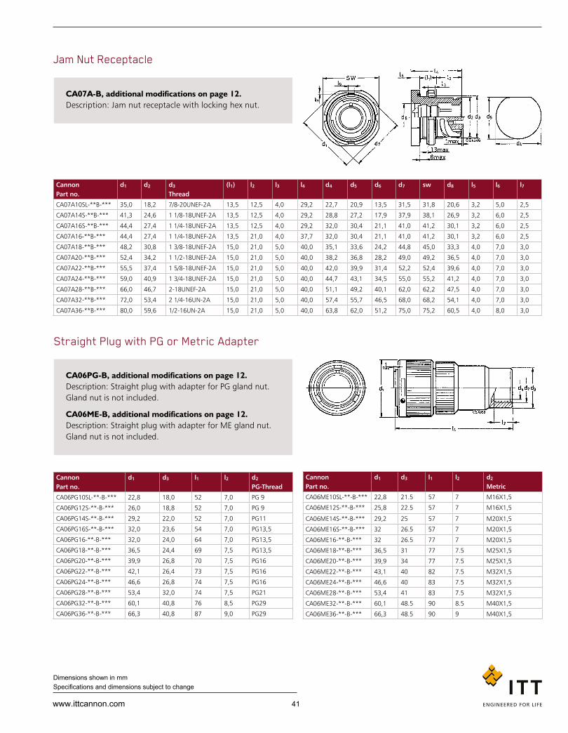
41www.ittcannon.com
Dimensions shown in mm Specifications and dimensions subject to change
Can non Part no.
d1 d2 d3
Thread(l1) l2 l3 l4 d4 d5 d6 d7 sw d8 l5 l6 l7
CA07A10SL-**B-*** 35,0 18,2 7/8-20UN EF-2A 13,5 12,5 4,0 29,2 22,7 20,9 13,5 31,5 31,8 20,6 3,2 5,0 2,5
CA07A14S-**B-*** 41,3 24,6 1 1/8-18UNEF-2A 13,5 12,5 4,0 29,2 28,8 27,2 17,9 37,9 38,1 26,9 3,2 6,0 2,5
CA07A16S-**B-*** 44,4 27,4 1 1/4-18UNEF-2A 13,5 12,5 4,0 29,2 32,0 30,4 21,1 41,0 41,2 30,1 3,2 6,0 2,5
CA07A16-**B-*** 44,4 27,4 1 1/4-18UNEF-2A 13,5 21,0 4,0 37,7 32,0 30,4 21,1 41,0 41,2 30,1 3,2 6,0 2,5
CA07A18-**B-*** 48,2 30,8 1 3/8-18UNEF-2A 15,0 21,0 5,0 40,0 35,1 33,6 24,2 44,8 45,0 33,3 4,0 7,0 3,0
CA07A20-**B-*** 52,4 34,2 1 1/2-18UNEF-2A 15,0 21,0 5,0 40,0 38,2 36,8 28,2 49,0 49,2 36,5 4,0 7,0 3,0
CA07A22-**B-*** 55,5 37,4 1 5/8-18UNEF-2A 15,0 21,0 5,0 40,0 42,0 39,9 31,4 52,2 52,4 39,6 4,0 7,0 3,0
CA07A24-**B-*** 59,0 40,9 1 3/4-18UNEF-2A 15,0 21,0 5,0 40,0 44,7 43,1 34,5 55,0 55,2 41,2 4,0 7,0 3,0
CA07A28-**B-*** 66,0 46,7 2-18UNEF-2A 15,0 21,0 5,0 40,0 51,1 49,2 40,1 62,0 62,2 47,5 4,0 7,0 3,0
CA07A32-**B-*** 72,0 53,4 2 1/4-16UN-2A 15,0 21,0 5,0 40,0 57,4 55,7 46,5 68,0 68,2 54,1 4,0 7,0 3,0
CA07A36-**B-*** 80,0 59,6 1/2-16UN-2A 15,0 21,0 5,0 40,0 63,8 62,0 51,2 75,0 75,2 60,5 4,0 8,0 3,0
Can non Part no.
d1 d3 l1 l2 d2
PG-Thread
CA06PG10SL-**-B-*** 22,8 18,0 52 7,0 PG 9
CA06PG12S-**-B-*** 26,0 18,8 52 7,0 PG 9
CA06PG14S-**-B-*** 29,2 22,0 52 7,0 PG11
CA06PG16S-**-B-*** 32,0 23,6 54 7,0 PG13,5
CA06PG16-**-B-*** 32,0 24,0 64 7,0 PG13,5
CA06PG18-**-B-*** 36,5 24,4 69 7,5 PG13,5
CA06PG20-**-B-*** 39,9 26,8 70 7,5 PG16
CA06PG22-**-B-*** 42,1 26,4 73 7,5 PG16
CA06PG24-**-B-*** 46,6 26,8 74 7,5 PG16
CA06PG28-**-B-*** 53,4 32,0 74 7,5 PG21
CA06PG32-**-B-*** 60,1 40,8 76 8,5 PG29
CA06PG36-**-B-*** 66,3 40,8 87 9,0 PG29
Can non Part no.
d1 d3 l1 l2 d2
Metric
CA06ME10SL-**-B-*** 22,8 21.5 57 7 M16X1,5
CA06ME12S-**-B-*** 25,8 22.5 57 7 M16X1,5
CA06ME14S-**-B-*** 29,2 25 57 7 M20X1,5
CA06ME16S-**-B-*** 32 26.5 57 7 M20X1,5
CA06ME16-**-B-*** 32 26.5 77 7 M20X1,5
CA06ME18-**-B-*** 36,5 31 77 7.5 M25X1,5
CA06ME20-**-B-*** 39,9 34 77 7.5 M25X1,5
CA06ME22-**-B-*** 43,1 40 82 7.5 M32X1,5
CA06ME24-**-B-*** 46,6 40 83 7.5 M32X1,5
CA06ME28-**-B-*** 53,4 41 83 7.5 M32X1,5
CA06ME32-**-B-*** 60,1 48.5 90 8.5 M40X1,5
CA06ME36-**-B-*** 66,3 48.5 90 9 M40X1,5
Jam Nut Receptacle
Straight Plug with PG or Metric Adapter
CA07A-B, additional modifications on page 12. Description: Jam nut receptacle with locking hex nut.
CA06PG-B, additional modifications on page 12. Description: Straight plug with adapter for PG gland nut. Gland nut is not included.
CA06ME-B, additional modifications on page 12. Description: Straight plug with adapter for ME gland nut. Gland nut is not included.
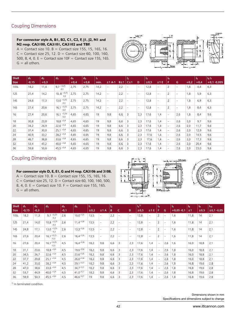
42 www.ittcannon.com
Dimensions shown in mm Specifications and dimensions subject to change
For connector style D, E, E1, G and H resp. CA3106 and 3108. A = Contact size 10. B = Contact size 15S, 15, 16S, 16. C = Contact size 25, 12. D = Contact size 60, 100, 160, 500, 8, 4, 0. E = Contact size 10. F = Contact size 15S, 16S. G = al l others.
Shell Size
d1 -0,15
d2 +0,3
d3 d4 +0,4
d5 +0,8
l1 min. ±1 A-1 B±1
l2
C±1 Dl3 ±0,5 ±1 E
l4
F G +0,2l5
+0,4l6 l7
+0,1 -0,005
10SL 18,2 11,4 9,7 +0,25
-0,3 2,75 2,75 14,2 – 2,2 – – 12,8 – 2 – 1,8 4,4 6,3
12S 21,4 14,2 10, 8 +0,25
-0,32,75 2,75 14,2 – 2,2 – – 12,8 – 2 – 1,8 5,9 6,3
14S 24,6 17,3 13,0 +0,25
-0,32,75 2,75 14,2 – 2,2 – – 12,8 – 2 – 1,8 6,9 6,3
16S 27,4 20,6 16,1 +0,25
-0,32,75 2,75 14,2 – 2,2 – – 12,8 – 2 – 1,8 8,4 6,3
16 27,4 20,6 16,1 +0,25
-0,34,65 4,65 19 9,8 6,6 3 2,3 17,6 1,4 – 2,6 1,8 8,4 9,6
18 30,8 23,8 18,8 ±0,4 4,65 4,65 19 9,8 6,6 3 2,3 17,6 1,4 – 2,6 2,0 9,7 9,6
20 34,2 26,9 22,6 ±0,4 4,65 4,65 19 9,8 6,6 3 2,3 17,6 1,4 – 2,6 2,0 11,7 9,6
22 37,4 30,0 25,1 ±0,4 4,65 4,65 19 9,8 6,6 3 2,3 17,6 1,4 – 2,6 2,0 12,9 9,6
24 40,9 33,2 28,2 ±0,4 4,65 4,65 19 9,8 6,6 3 2,3 17,6 1,4 – 2,6 2,0 14,5 9,6
28 46,7 38,8 33,6 ±0,4 4,65 4,65 19 9,8 6,6 3 2,3 17,6 1,4 – 2,6 2,0 17,3 9,6
32 53,4 45,2 40,0 ±0,4 4,65 4,65 19 9,8 6,6 3 2,3 17,6 1,4 – 2,6 2,0 20,4 9,6
36 59,6 50,6 45,5 ±0,4 4,65 4,65 19 9,8 6,6 3 2,3 17,6 1,4 – 2,6 2,0 23,0 9,6
Shell Size
d1 -0,15
d2 -0,3
d3 d4 -0,1
d6 l1 ±0,2 ±1 A
l2
B C Dl31) ±0,5 ±1 E
l4
F Gl5
+0,05 -0,1l8
±1l9
±0,5l10
±0,1 -0,05
10SL 18,2 11,3 9,7 +0,25
–0,32,6 10,0+0,3 13,5 – 2,2 – – 12,8 – 2 – 1,6 11,8 14 2,1
12S 21,4 14,0 10,8 +0,25
–0,32,6 11,4+0,6 13,5 – 2,2 – – 12,8 – 2 – 1,6 11,8 14 2,1
14S 24,8 17,1 13,0 +0,25
–0,32,6 13,3+0,6 13,5 – 2,2 – – 12,8 – 2 – 1,6 11,8 14 2,1
16S 27,6 20,4 16,1+0,25
–0,32,6 16,4+0,6 13,5 – 2,2 – – 12,8 – 2 – 1,6 11,8 14 2,1
16 27,6 20,4 16,1+0,25
–0,34,5 16,4+0,6 18,2 9,8 6,6 3 2,3 17,6 1,4 – 2,6 1,6 16,0 18,8 2,1
18 31,1 23,6 18,8 ±0,4 4,5 19,6+0,6 18,2 9,8 6,6 3 2,3 17,6 1,4 – 2,6 1,8 16,0 18,8 2,1
20 34,5 26,7 22,6 ±0,4 4,5 23,6+0,6 18,2 9,8 6,6 3 2,3 17,6 1,4 – 2,6 1,8 16,0 18,8 2,1
22 37,7 29,8 25,1 ±0,4 4,5 26,0+0,6 18,2 9,8 6,6 3 2,3 17,6 1,4 – 2,6 1,8 16,0 18,8 2,1
24 41,2 33,0 28,2 ±0,4 4,5 29,1+0,7 18,2 9,8 6,6 3 2,3 17,6 1,4 – 2,6 1,8 16,8 19,6 2,8
28 47,0 38,6 33,6 ±0,4 4,5 34,7+0,7 18,2 9,8 6,6 3 2,3 17,6 1,4 – 2,6 1,8 16,8 19,6 2,8
32 53,7 44,9 40,0 ±0,4 4,5 41,0+0,7 18,2 9,8 6,6 3 2,3 17,6 1,4 – 2,6 1,8 16,8 19,6 2,8
36 59,9 50,3 45,5 ±0,4 4,5 46,6+0,7 19 9,8 6,6 3 2,3 17,6 1,4 – 2,6 1,8 16,8 19,6 2,8
Coupling Dimensions
Coupling Dimensions
For connector style A, B1, B2, C1, C2, F, J1, J2, N1 and N2 resp. CA3100, CA3101, CA3102 and TBF. A = Contact size 10. B = Contact size 15S, 15, 16S, 16. C = Contact size 25, 12. D = Contact size 60, 100, 160, 500, 8, 4, 0. E = Contact size 10F = Contact size 15S, 16S. G = al l others.
1) In terminated condition.

43www.ittcannon.com
Dimensions shown in mm Specifications and dimensions subject to change
General Information Scope This specification describes a CA-B connector with a sealing effectiveness up to IP69K. This connector is interchangeable with the corresponding types as per MIL-C-5015 and VG95234, as they offer the same mounting dimensions and contact arrangements. These connectors are without spring washer, friction ring and grommet.
Recommended Method of Mounting Connector shell is fixed with 4 screws on the housing. In combination with universal endbell and an o-ring between flange receptacle and wall the connector will reach IP68 sealing (1 bar, 16h) and IP69K sealing acc. to ISO20653.
Ratings & Characteristics
Locking Device Bayonet Coupling
Contact Type Crimp or Solder Contacts
Electrical Characteristics In accordance with VG95234 bayonet coupling
Environmental Characteristics In accordance with VG95234 bayonet coupling Deviance with plating A240: 500h salt spray test with mated pair Deviance with plating A34: 48h salt spray test
Water tightness for mated connector IP68 (1bar, 16h) and IP69K in combination with universal endbell and o-ring (flange receptacle to wall)
Normative references
DIN EN 61984 Electrical Connector, safety requirements and tests
IEC 60068 Environmental tests
IEC 60352 Crimp connection and requirements
IEC 60512 Electrical Connector, measuring and test procedure
IEC 60529 Specification for degrees of protection provided by enclosures
VG 95373 Electromagnetic compatibility
CAB IP69K
Designation Material Finish
Shell
Aluminium-alloy According to order reference
Coupling Nut
Endbell
Cone Ring
Clamping Nut
Clutch Spring
Circlip Spring Steel -
Contact Copper-alloy Silver Plated and Passivated
Clutch Ring PPS -
Shielding Sleeve PA66
Clamping Ring PBT
Insulator
CR-rubber -Sealing Ring
Grommet
O-ring
Mechanical Characteristics

44 www.ittcannon.com
Dimensions shown in mm Specifications and dimensions subject to change
Series
Shell style
Class
Sealing Material
Shell Size
Contact Arrangement
Contact Type
Insulator position
Coupling Mechanism
Dash
Mo di fica tion
Cable Sealing Area
CA 06 X 20 29H S –W 13-D17-A240B
How to order Cannon Order reference
Explanation Series CA
Shell style 01 = Cable connection receptacle 02 = Wall mounting receptacle, front panel mounting 06 = Straight plug, without spring washer, friction ring and grommet
Class X=Environmental (IP69K)
Sealing Material Without = CR-Sealing (cable seal: Silicone) H= FKM sealing (cable seal: Silicone), consult factory
Shell Sizes Available shell sizes: 10SL, 14S, 18, 20, 22, 28
Contact Arrangement See pages 13-23
Contact Type P= Pin, S=Socket
Coupling Mechanism B=Bayonet
Insulator Position See pages 13-23, no identification for normal position
Cable Sealing Area D07 = with Universal Endbell (IP69K), straight version: #10SL, #14S, #20 (wire size 4,5 – 7,2mm) D09 = with Universal Endbell (IP69K), straight version: #14S, #20 (wire size 6,5 - 9,3mm) D11 = with Universal Endbell (IP69K), straight version: #14S, #18, #20 (wire size 8,0 – 10,3mm) D13 = with Universal Endbell (IP69K), straight version: #18, #20, #22 (wire size 9,0 – 12,5mm D14 = with Universal Endbell (IP69K), straight version: #18, #20, #22, #28 (wire size 11,5 – 14,2mm) D17 = with Universal Endbell (IP69K), straight version: #20, #22, #28 (wire size 14,5 – 16,6mm)
Mo di fi ca tion 13 – shielded version, solder pot contacts 14 – shielded version, metric crimp contacts 15 – shielded version, AWG crimp contacts A176 – gold plated contact, see pages 54-55 A239 – Zinc Cobalt black plating, VG approved A232 – Zinc cobalt black plating A233 – Zinc cobalt green plating A240 – Zinc Nickel blue grey plating F0 – less contacts, contacts to be ordered separately, see page 54-59

45www.ittcannon.com
Dimensions shown in mm Specifications and dimensions subject to change
Cable Connecting Receptacle with universal endbell
Box Mounting Receptacle for front panel mounting
Endbell: Universal Endbell Shielding: Yes Sealing: IP67, IP68, IP69K in mated condition
CA01X… Straight receptacle for cable connection with universal endbell.
Please pay attention that the diameter of the cable is within the range ØH.
Endbell: None Shielding: None Sealing: IP67, IP68, IP69K in mated condition
CA02X…-B… Box Mounting Receptacle
Front Panel Mounting with O-Ring Sealing for IP69K
Part no. ØA -0.15
ØB ± 0,2
C + 0,4
D ± 0,2
E max
ØF max
G ± 0,2
ØH Range min max
CA01X10SL-**…D07… 18.2 17.9 18.2 2.8 85 25.2 20.6 4.5 - 7.2 mm
CA01X14S-**…D07… 24.6 17.9 18.2 3.2 87 29.8 25.4 4.5 - 7.2 mm
CA01X14S-**…D09… 24.6 21.0 18.2 3.2 87 29.8 25.4 6.5 - 9.3 mm
CA01X14S-**…D11… 24.6 24.0 18.2 3.2 87 29.8 25.4 8.0 - 10.3 mm
CA01X18-**…D11… 30.8 24.0 23.05 4.0 93 34.8 31.7 8.0 - 10.3 mm
CA01X18-**…D13… 30.8 27.4 23.05 4.0 93 34.8 31.7 9.0 - 12.5 mm
CA01X18-**…D14… 30.8 30.0 23.05 4.0 93 34.8 31.7 11.5 - 14.2 mm
CA01X20-**…D07… 34.2 17.9 23.05 4.0 96 37.8 34.9 4.5 - 7.2 mm
CA01X20-**…D09… 34.2 21.0 23.05 4.0 96 37.8 34.9 6.5 - 9.3 mm
CA01X20-**…D11… 34.2 24.0 23.05 4.0 96 37.8 34.9 8.0 - 10.3 mm
CA01X20-**…D13… 34.2 27.4 23.05 4.0 96 37.8 34.9 9.0 - 12.5 mm
CA01X20-**…D17… 34.2 33.6 23.05 4.0 96 37.8 34.9 14.5 - 16.6 mm
CA01X22-**…D13… 37.4 27.4 23.05 4.0 100 41.1 38.1 9.0 - 12.5 mm
CA01X22-**…D14… 37.4 30.0 23.05 4.0 100 41.1 38.1 11.5 - 14.2 mm
CA01X22-**…D17… 37.4 33.6 23.05 4.0 100 41.1 38.1 14.5 - 16.6 mm
CA01X28-**…D17… 37.4 33.6 24.05 4.0 108 50.9 47.6 14.5 - 16.6 mm
Part no. A -0.15
B + 0,4
C ± 0,2
D ± 0,3
E max
F ± 0,1
G ± 0,3
H H13
X / Contact size 15 25 100
CA02X10SL-**-P*-B 18.2 14.2 2.8 24.7 16.2 18.2 25.4 3.2 13.6 - -
CA02X14S-**-P*-B 24.6 14.2 3.2 24.7 19.2 23 30 3.2 13.2 - -
CA02X18-**-P*-B 30.8 19.0 4.0 33.8 25.6 27.0 35.0 3.2 17.1 17.1 18.7
CA02X20-**-P*-B 34.2 19.0 4.0 33.8 29.0 29.4 38.0 3.2 17.1 17.1 18.7
CA02X22-**-P*-B 37.4 19 4.0 33.8 32.2 31.8 41 3.2 17.1 17.1 18.7
CA02X28-**-P*-B 46.7 20.6 4.0 33.8 41.4 39.7 50.8 3.7 15.5 15.5 17.1

46 www.ittcannon.com
Dimensions shown in mm Specifications and dimensions subject to change
Straight Plug with universal endbell
Endbell: Universal Endbell Shielding: Yes, with Modification Code Sealing: IP67, IP68, IP69K in mated condition
CA06X…-B… Straight plug with universal endbell.
Please pay attention that the diameter of the cable is within the sealing range ØD.
Part no. ØA max
B max
ØE ± 0,2
ØD Sealing Range min max
CA06X10SL-**…D07… 22.8 82 17.9 4.5 - 7.2 mm
CA06X14S-**…D07… 29.2 82 17.9 4.5 - 7.2 mm
CA06X14S-**…D09… 29.2 82 21.0 6.5 - 9.3 mm
CA06X14S-**…D11… 29.2 82 24.0 8.0 - 10.3 mm
CA06X18-**…D11… 36.5 88 24.0 8.0 - 10.3 mm
CA06X18-**…D13… 36.5 88 27.4 9.0 - 12.5 mm
CA06X18-**…D14… 36.5 88 30.0 11.5 - 14.2 mm
CA06X20-**…D07… 39.9 92 17.9 4.5 - 7.2 mm
CA06X20-**…D09… 39.9 92 21.0 6.5 - 9.3 mm
CA06X20-**…D11… 39.9 92 24.0 8.0 - 10.3 mm
CA06X20-**…D13… 39.9 92 27.4 9.0 - 12.5 mm
CA06X20-**…D14… 39.9 92 27.4 9.0 - 12.5 mm
CA06X20-**…D17… 39.9 92 33.6 14.5 - 16.6 mm
CA06X22-**…D13… 43.1 98 27.4 9.0 - 12.5 mm
CA06X22-**…D14… 43.1 98 30.0 11.5 - 14.2 mm
CA06X22-**…D17… 43.1 98 33.6 14.5 - 16.6 mm
CA06X28-**…D14… 43.1 98 33.6 14.5 - 16.6 mm
CA06X28-**…D17… 53.4 105 33.6 14.5 - 16.6 mm

47www.ittcannon.com
Dimensions shown in mm Specifications and dimensions subject to change
Plastic Protecting Caps
Part no. Protecting cap for Receptacles Plugs Shell size Shell size
Ø A max.
Ø B -0,2
Ø D +0,2
F ±0,2
G ±0,2
H max.
025-8636-005 10S/10SL – 22,8 17,7 19,7 10,7 14,2 15,9
025-8636-006 – 10S/10SL 22,8 10,7 12,9 15,5 17,0 18,7
025-8636-008 – 12S 26,0 13,4 15,8 15,5 17,0 18,7
025-8636-010 12S/12 – 26,0 20,9 22,9 10,7 14,2 15,9
025-8636-016 14S/14 – 29,2 24,1 26,1 10,7 14,2 15,9
025-8636-017 – 14S 29,2 16,5 19,1 15,5 17,0 18,7
025-8636-018 – 14 29,2 16,5 19,1 20,2 21,7 23,4
025-8636-022 – 16S 32,0 19,8 22,4 15,5 17,0 18,7
025-8636-024 – 16 32,0 19,8 22,4 20,2 21,7 23,4
025-8636-025 16S – 32,0 26,9 28,9 10,7 14,2 15,9
025-8636-026 16 – 32,0 26,9 28,9 17,5 19,0 20,7
025-8636-034 18 – 36,5 30,3 32,3 17,5 19,0 20,7
025-8636-036 – 18 36,5 23,0 25,6 20,2 21,7 23,4
025-8636-042 20 – 39,9 33,7 35,7 17,5 19,0 20,7
025-8636-044 – 20 39,9 26,1 28,8 20,2 21,7 23,4
025-8636-048 – 22 43,1 29,2 31,9 20,2 21,7 23,4
025-8636-049 22 – 43,1 36,9 38,9 17,5 19,0 20,7
025-8636-053 24 – 46,6 40,4 42,4 19,1 20,6 22,3
025-8636-054 – 24 46,6 32,4 35,1 20,2 21,7 23,4
025-8636-058 28 – 53,4 46,2 48,2 19,1 20,6 22,3
025-8636-060 – 28 53,4 38,0 40,7 20,2 21,7 23,4
025-8636-061 – 32 60,1 44,3 47,2 20,2 21,7 23,4
025-8636-062 32 – 64,9 52,9 54,9 20,7 22,2 23,9
025-8636-064 36 – 71,1 59,1 60,1 20,7 22,2 23,9
025-8636-065 – 36 66,3 49,7 51,6 20,2 21,7 23,4

48 www.ittcannon.com
Dimensions shown in mm Specifications and dimensions subject to change
A66*** A239 A240 d1 max.
d2 +0,5
l1 ±10
l2 max.
CA121003-901 CA121003-1181 CA121003-1161 23.4 4.3 100 19.5
CA121003-902 CA121003-1182 CA121003-1162 26.6 4.3 100 19.5
CA121003-903 CA121003-1183 CA121003-1163 29.8 4.3 100 19.5
CA121003-904 CA121003-1184 CA121003-1164 32.6 4.3 100 19.5
CA121003-905 CA121003-1185 CA121003-1165 32.6 4.3 113 24.5
CA121003-906 CA121003-1186 CA121003-1166 36.7 4.3 113 24.5
CA121003-907 CA121003-1187 CA121003-1167 40.1 4.3 127 24.5
CA121003-908 CA121003-1188 CA121003-1168 43.3 4.3 127 24.5
CA121003-909 CA121003-1189 CA121003-1169 46.8 4.3 127 24.5
CA121003-910 CA121003-1190 CA121003-1170 52.6 5.5 169 24.5
CA121003-911 CA121003-1191 CA121003-1171 59.3 5.5 169 24.5
CA121003-912 CA121003-1192 CA121003-1172 65.5 5.5 169 24.5
Shell size
VG95234* Cannon A66 Cord length (mm)
d2 +0,5
10SL VG95234KA10SL CAB81-10SL-D 400 4.3
12S - CAB81-12S-D 400 4.3
14S VG95234KA14S CAB81-14S-D 400 4.3
16S VG95234KA16S CAB81-16S-D 400 4.3
16 VG95234KA16 CAB81-16-D 400 4.3
18 VG95234KA18 CAB81-18-D 400 4.3
20 VG95234KA20 CAB81-20-D 400 4.3
22 VG95234KA22 CAB81-22-D 400 4.3
24 VG95234KA24 CAB81-24-D 400 4.3
28 VG95234KA28 CAB81-28-D 400 5.5
32 VG95234KA32 CAB81-32-D 400 5.5
36 VG95234KA36 CAB81-36-D 400 5.5
Shell size
VG95234* Cannon A66 A232 A233 A239 A240 d1
max.d2
+0,5l1
±10l2
max.
10SL VG95234KR10SL CA121003-1 CA121003-71 CA121003-121 CA121003-141 CA121003-161 23.4 4.3 100 19.5
12S - CA121003-2 CA121003-72 CA121003-122 CA121003-142 CA121003-162 26.6 4.3 100 19.5
14S VG95234KR14S CA121003-3 CA121003-73 CA121003-123 CA121003-143 CA121003-163 29.8 4.3 100 19.5
16S VG95234KR16S CA121003-4 CA121003-74 CA121003-124 CA121003-144 CA121003-164 32.6 4.3 100 19.5
16 VG95234KR16 CA121003-5 CA121003-75 CA121003-125 CA121003-145 CA121003-165 32.6 4.3 113 24.5
18 VG95234KR18 CA121003-6 CA121003-76 CA121003-126 CA121003-146 CA121003-166 36.7 4.3 113 24.5
20 VG95234KR20 CA121003-7 CA121003-77 CA121003-127 CA121003-147 CA121003-167 40.1 4.3 127 24.5
22 VG95234KR22 CA121003-8 CA121003-78 CA121003-128 CA121003-148 CA121003-168 43.3 4.3 127 24.5
24 VG95234KR24 CA121003-9 CA121003-79 CA121003-129 CA121003-149 CA121003-169 46.8 4.3 127 24.5
28 VG95234KR28 CA121003-10 CA121003-80 CA121003-130 CA121003-150 CA121003-170 52.6 5.5 169 24.5
32 VG95234KR32 CA121003-11 CA121003-81 CA121003-131 CA121003-151 CA121003-171 59.3 5.5 169 24.5
36 VG95234KR36 CA121003-12 CA121003-82 CA121003-132 CA121003-152 CA121003-172 65.5 5.5 169 24.5
Metal Protecting Caps for Receptacles with Cord
Metal Protecting Caps for Receptacles with Chain
* Also available with VG approved ZnCo black plating. Add modification code -H, for example: VG95234KA10SLH.
Dust caps delivered with terminal link unassembled
Dust caps delivered with terminal link assembled (cord length l1)
Dust caps delivered with terminal link assembled (cord length l1)
* Also available with VG approved ZnCo black plating. Add modification code -H, for example:VG95234KR10SLH.

49www.ittcannon.com
Dimensions shown in mm Specifications and dimensions subject to change
A66 A239 A240*** d1
max.d2
+0,5l1
±10l2
max.
CA121004-901 CA121004-1141 CA121004-1161 20.7 4.3 100 29
CA121004-902 CA121004-1142 CA121004-1162 23.9 4.3 113 29
CA121004-903 CA121004-1143 CA121004-1163 27.1 4.3 113 29
CA121004-904 CA121004-1144 CA121004-1164 29.9 4.3 113 29
CA121004-905 CA121004-1145 CA121004-1165 29.9 4.3 127 37
CA121004-906 CA121004-1146 CA121004-1166 33.3 4.3 127 37
CA121004-907 CA121004-1147 CA121004-1167 36.7 4.7 140 37
CA121004-908 CA121004-1148 CA121004-1168 39.9 4.7 140 37
CA121004-909 CA121004-1149 CA121004-1169 43.4 4.7 140 37
CA121004-910 CA121004-1150 CA121004-1170 49.2 4.7 197 37
CA121004-911 CA121004-1151 CA121004-1171 55.9 5.5 197 37
CA121004-912 CA121004-1152 CA121004-1172 62.1 5.5 197 37
Shell size
VG95234* Cannon A66 Cord length (mm)
d2
+0,5
10SL VG95234KC10SL CAB80-10SL-D 400 4.3
12S - CAB80-12S-D 400 4.3
14S VG95234KC14S CAB80-14S-D 400 4.3
16S VG95234KC16S CAB80-16S-D 400 4.3
16 VG95234KC16 CAB80-16-D 400 4.3
18 VG95234KC18 CAB80-18-D 400 4.3
20 VG95234KC20 CAB80-20-D 400 4.7
22 VG95234KC22 CAB80-22-D 400 4.7
24 VG95234KC24 CAB80-24-D 400 4.7
28 VG95234KC28 CAB80-28-D 400 4.7
32 VG95234KC32 CAB80-32-D 400 5.5
36 VG95234KC36 CAB80-36-D 400 5.5
Shell size
VG95234* Cannon A66 A232 A233 A239 A240 d1
max.d2
+0,5l1
±10l2
max.
10SL VG95234KB10SL CA121004-1 CA121004-71 CA121004-121 CA121004-141 CA121004-161 20.7 4.3 100 29
12S - CA121004-2 CA121004-72 CA121004-122 CA1t21004-142 CA121004-162 23.9 4.3 113 29
14S VG95234KB14S CA121004-3 CA121004-73 CA121004-123 CA121004-143 CA121004-163 27.1 4.3 113 29
16S VG95234KB16S CA121004-4 CA121004-74 CA121004-124 CA121004-144 CA121004-164 29.9 4.3 113 29
16 VG95234KB16 CA121004-5 CA121004-75 CA121004-125 CA121004-145 CA121004-165 29.9 4.3 127 37
18 VG95234KB18 CA121004-6 CA121004-76 CA121004-126 CA121004-146 CA121004-166 33.3 4.3 127 37
20 VG95234KB20 CA121004-7 CA121004-77 CA121004-127 CA121004-147 CA121004-167 36.7 4.7 140 37
22 VG95234KB22 CA121004-8 CA121004-78 CA121004-128 CA121004-148 CA121004-168 39.9 4.7 140 37
24 VG95234KB24 CA121004-9 CA121004-79 CA121004-129 CA121004-149 CA121004-169 43.4 4.7 140 37
28 VG95234KB28 CA121004-10 CA121004-80 CA121004-130 CA121004-150 CA121004-170 49.2 4.7 197 37
32 VG95234KB32 CA121004-11 CA121004-81 CA121004-131 CA121004-151 CA121004-171 55.9 5.5 197 37
36 VG95234KB36 CA121004-12 CA121004-82 CA121004-132 CA121004-152 CA121004-172 62.1 5.5 197 37
Metal Protecting Caps for Plugs with Chain
Metal Protecting Caps for Plugs with Cord
Dust caps delivered with terminal link unassembled
Dust caps delivered with terminal link assembled (cord length l1)
Dust caps delivered with terminal link assembled (cord length l1)
* Also available with VG approved ZnCo black plating. Add modification code -H, for example: VG95234KC10SLH.
* Also available with VG approved ZnCo black plating. Add modification code -H, for example:VG95234KB10SLH.

50 www.ittcannon.com
Dimensions shown in mm Specifications and dimensions subject to change
Shell size
VG95234 Part No.
Cannon Part No.
d1 -0,15
d2 ±0,2
l1 ±0,3
l2 ±0,1
l3 max.
l4 +0,3
10SL VG95234BOD10SL CA3105E10SL-B 18,2 3,2 25,4 18,2 17,5 14,2
12S CA3105E12S-B 21,4 3,2 28,0 20,6 18,0 14,2
14S VG95234BOD14S CA3105E14S-B 24,6 3,2 30,0 23,0 18,0 14,2
16S VG95234BOD16S CA3105E16S-B 27,4 3,2 32,5 24,6 18,0 14,2
16 VG95234BOD16 CA3105E16-B 27,4 3,2 32,5 24,6 23,5 19,0
18 VG95234BOD18 CA3105E18-B 30,8 3,2 35,0 27,0 23,5 19,0
20 VG95234BOD20 CA3105E20-B 34,2 3,2 38,0 29,4 23,5 19,0
22 VG95234BOD22 CA3105E22-B 37,4 3,2 41,0 31,8 23,5 19,0
24 VG95234BOD24 CA3105E24-B 40,9 3,7 44,5 34,9 25,5 20,6
28 VG95234BOD28 CA3105E28-B 46,7 3,7 50,8 39,7 25,5 20,6
32 VG95234BOD32 CA3105E32-B 53,4 4,3 57,0 44,5 27,0 22,2
36 VG95234BOD36 CA3105E36-B 59,6 4,3 63,5 49,2 27,0 22,2
Shell size
Cannon Part no. with thread Style A
Cannon Part no. with through holes Style B
d1 l1 ±0,25
l2 ±0,3
l3 l4+0,3
Style A d2
Style B d2
±0,3
10SL 248-8513-000 248-8501-000 18,2 25,4 18,2 21,1 18,3 M4 3,2
12S 248-8514-000 248-8502-000 21,4 28,0 20,6 21,5 18,3 M4 3,2
14S 248-8515-000 248-8503-000 24,6 30,0 23,0 21,5 18,3 M4 3,2
16S 248-8516-000 248-8504-000 27,4 32,5 24,6 21,5 18,3 M4 3,2
16 248-8517-000 248-8505-000 27,4 32,5 24,6 24,8 21,6 M4 3,2
18 248-8518-000 248-8506-000 30,8 35,0 27,0 27,2 23,15 M4 3,2
20s 248-8519-000 248-8507-000 34,2 38,0 29,4 27,2 23,15 M4 3,2
22 248-8520-000 248-8508-000 37,4 41,0 31,8 27,2 23,15 M4 3,2
24 248-8521-000 248-8509-000 40,9 44,5 34,9 27,2 23,15 M4 3,7
28 248-8522-000 248-8510-000 46,7 50,8 39,7 28,2 24,15 M5 3,7
32 248-8523-000 248-8511-000 53,4 57,0 44,5 28,2 24,15 M5 4,4
36 248-8524-000 248-8512-000 59,6 63,5 49,2 28,2 24,15 M5 4,4
Dummy Receptacles
Dummy Receptacles
Front panel mounting (rear side open) VG95234 Style BOD (Flange with through-holes)CA3105-B
Rear panel mounting (rear side closed). Available as Style A with through holes and Style B with threaded holes.

51www.ittcannon.com
Dimensions shown in mm Specifications and dimensions subject to change
Shell size
VG95234 Part No.
For contact size metr. AWG
d1 ±0,1
d2 ±0,2
l1 ±0,1
l2 ±0,3
Colour Part No.
20 VG95234B20 10 2,3 3,0 2,4 9,7 red 225-1000-000
16S VG95234B16S 15S 16S 2,8 3,7 1,5 4,8 natural 225-8510-000
16 VG95234B16 15S/15 16S/16 2,8 3,7 3,2 11,9 blue 225-0017-000
12 VG95234B12 25/25A 12 3,7 4,6 3,2 11,9 yellow 225-0018-000
8 VG95234B08 60/100 8 5 5,8 3,2 11,9 white 225-0019-000
4 VG95234B04 160 4 7,6 8,5 3,2 11,9 green 225-8502-000
0 VG95234B00 500 0 12,8 13,5 3,2 11,9 black 225-8503-000
Size Part no. d9
10SL 980-8550-000 9,0
12S 980-8551-000 11,5
14S 980-8552-000 14,0
16/16S 980-8553-000 17,0
18 980-8554-000 19,5
20 980-8555-000 22,5
22 980-8556-000 25,4
24 980-8557-000 28,5
28 980-8558-000 34,0
32 980-8559-000 40,0
36 980-8560-000 45,0
Sealing Rings
Wire Hole Fillers
Accessories
For use on the barrel of the plug; interfacial seal.
Used to close unused contact cavities. Contacts have to be installed while the wire hole fillers are mounted into the relevant open grommet holes.

52 www.ittcannon.com
Dimensions shown in mm Specifications and dimensions subject to change
VG95234 Part No.
Former Designation MS
Shell size suitable for connectors acc. MS
A-Thread l2 max.
d1 max.
l1 max.
l3 max.
Max. Shell-Weight g
VG95234KK 4 MS3057- 4A* 10SL, 12S, 5/7-24NEF-2B 10,5 7,9 20,8 22,5 15
VG95234KK 6 MS3057- 6A* 14S, 3/4-20UN EF-2B 10,5 11,1 22,4 27,4 20
VG95234KK 8 MS3057- 8A* 16S, 16 7/8-20UN EF-2B 10,5 14,2 24,0 29,8 25
VG95234KK10 MS3057-10A* 18 1-20UN EF-2B 10,5 15,8 24,0 32,2 25
VG95234KK12 MS3057-12A* 20, 22 1 3/16-18NEF-2B 10,5 19,0 24,0 37,4 35
VG95234KK16 MS3057-16A* 24, 28 1 7/16-18NEF-2B 10,5 23,7 26,4 43,5 45
VG95234KK20 MS3057-20A* 32 1 3/4-18NS-2B 12,0 31,8 28,0 51,7 55
VG95234KK24 MS3057-24A* 36 2-18NS-2B 13,7 34,6 29,6 57,8 75
Cable Clamps
without telescoping bushing VG95234 Style KK
* WB = Cable clamp with telescoping bushing.
Shell size
VG95234 Part No.
Cannon Part no.
d1 d2 d3 l Weight g
10SL VG95234KT10SL 012-8552-000 8.0 6.6 9.9 70.0 4
14S VG95234KT14S 012-8554-000 10.9 9.1 12.7 67.0 5
16S, 16 VG95234KT16 012-0218-000 14.0 11.1 19.0 64.0 6
18 VG95234KT18 012-0219-000 15.7 14.3 22.0 60.0 4
20, 22 VG95234KT20 012-0220-000 18.8 15.9 26.9 57.0 7
24, 28 VG95234KT24 012-8556-000 23.6 21.5 33.3 54.0 13
32 VG95234KT32 012-8558-000 31.5 26.8 40.4 51.0 26
36 VG95234KT36 012-0223-000 34.7 31.8 46.8 48.0 30
24.28 - 012-8555-000 21.2 16.6 26.9 57.0 13
32 - 012-8557-000 26.5 21.5 33.3 54.0 26
Shell size Combination of:
24, 28 012-8556-000 and 012-8555-000
32 012-8558-000 and 012-8557-000
36 012-0223-000 and 012-8558-000
Telescoping Bushings
Telescoping bushings (used with MS3057A resp. VG95234KK cable clamp) keep dirt, oil and dust out of the endbell. Taping or wrapping wires is eliminated since bushing protects wires guided through the clamp. Material: Polychloroprene
The Commercial versions allow for the following combinations of two bushings used together in order to decrease the inner diameter as required.

53www.ittcannon.com
Dimensions shown in mm Specifications and dimensions subject to change
Gaskets
Thickness of gaskets =1,0 mm (Made of Polychloropren, mod. “1”). 0,5 mm (Made of Alu-Flex, mod. “2”) VG95234 Style DA for front panel mounting VG95234 Style DH for rear panel mounting
For front panel mounting
For rear panel mounting
X = insert “1” (electrically non-conductive) or “2” (electrically conductive).
Shell size
VG95234 Part No.
Part no. Version Polychloropen1
Part no.VersionAlu-Flex2
l ±0,5
e ±0,2
d1 +1
d2
+0,5Weight g max.
10SL VG95234 DA 10SL-X 075-8512-000 075-8512-001 25,4 18,2 15,7 4,2 2
12S 075-8513-000 075-8513-001 28,0 20,6 18,9 4,2 2
14S VG95234 DA 14S-X 075-8514-000 075-8514-001 30,0 23,0 22,1 4,2 2
16/16S VG95234 DA 16-X 075-8515-000 075-8515-001 32,5 24,6 25,3 4,2 2
18 VG95234 DA 18-X 075-8516-000 075-8516-001 35,0 27,0 28,4 4,2 2
20 VG95234 DA 20-X 075-8517-000 075-8517-001 38,0 29,4 31,6 4,2 2
22 VG95234 DA 22-X 075-8518-000 075-8518-001 41,0 31,8 34,8 4,2 2
24 VG95234 DA 24-X 075-8519-000 075-8519-001 44,5 34,9 38,0 4,2 2
28 VG95234 DA 28-X 075-8520-000 075-8520-001 50,8 39,7 44,3 5,1 2
32 VG95234 DA 32-X 075-8521-000 075-8521-001 57,0 44,5 50,7 5,1 2
36 VG95234 DA 36-X 075-8522-000 075-8522-001 63,5 49,2 57,0 5,1 2
Shell size
VG95234 Part No.
Part no. Version Polychloropen1
Part no.VersionAlu-Flex2
l ±0,5
e ±0,2
d1 +1
d2
+0,5Weight g max.
10SL VG95234 DH 10SL-X 075-8501-000 075-8501-001 25,4 18,2 18,2 4,2 2
12S 075-8502-000 075-8502-001 28,0 20,6 21,4 4,2 2
14S VG95234 DH 14S-X 075-8503-000 075-8503-001 30,0 23,0 24,6 4,2 2
16/16S VG95234 DH 16-X 075-8504-000 075-8504-001 32,5 24,6 27,4 4,2 2
18 VG95234 DH 18-X 075-8505-000 075-8505-001 35,0 27,0 30,8 4,2 2
20 VG95234 DH 20-X 075-8506-000 075-8506-001 38,0 29,4 34,2 4,2 2
22 VG95234 DH 22-X 075-8507-000 075-8507-001 41,0 31,8 37,4 4,2 2
24 VG95234 DH 24-X 075-8508-000 075-8508-001 44,5 34,9 40,9 4,2 2
28 VG95234 DH 28-X 075-8509-000 075-8509-001 50,8 39,7 46,7 5,1 2
32 VG95234 DH 32-X 075-8510-000 075-85010-001 57,0 44,5 53,4 5,1 2
36 VG95234 DH 36-X 075-8511-000 075-85011-001 63,5 49,2 59,6 5,1 2

54 www.ittcannon.com
Dimensions shown in mm Specifications and dimensions subject to change
Size 15S/16S, 15/16, 25/12, 60/100/8, 160/4, 500/0
Size 10/20
Pin contacts
Standard contacts and contacts with reduced termination diameter Pin contacts Finish A36 – 5 µm silver plated and passivated A176 – 2 µm nickel plated, min. 0,5 µm gold plated
Contact size
VG95234 Part No.
Wire size mm2
AWG Part no. with finish Standard: A36 silver plated
Part no. with finish Mod. Code: A176 gold plated
d1 -0,05
d4 d6 d7 l1 ±0,15
l3 ±0,5
Color Code
10/20 VG95234P10 0,5-1,0 20/18 030-8585-000 030-8585-006 1,04 1,5 - 0,5 1,5 + 0,5 2,4 -0,05 28,4 4,75 –
VG95234P10-001 0,2-0,4 26/22 030-8585-010 030-8585-016 1,04 1,5 - 0,5 0,9 + 0,5 2,4 -0,05 28,4 4,75 blue
15S/16S VG95234P15S 0,75-1,5 18/16 030-8586-000 030-8586-006 1,6 1,75 -0,1 1,75 +0,08 2,75 -0,05 27,4 3,85 –
VG95234P15S-002 0,3-0,6 22/20 330-8744-000 330-8744-006 1,6 1,75 -0,1 1,2 +0,1 2,75 -0,05 27,4 3,85 red
VG95234P15S-001 0,14-0,38 22/26 030-8586-010 030-8586-016 1,6 1,75 -0,1 0,9 +0,05 2,75 -0,05 27,4 3,85 blue
15/16 VG95234P15 0,75-1,5 18/16 030-8587-000 030-8587-006 1,6 1,75 -0,1 1,75 +0,08 2,75 -0,05 31,4 7,9 –
VG95234P15-002 0,3-0,6 22/20 330-8659-000 330-8659-006 1,6 1,75 -0,1 1,2 +0,1 2,75 -0,05 31,4 7,9 red
VG95234P15-001 0,14-0,38 22/26 030-8587-030 030-8587-036 1,6 1,75 -0,1 0,9 +0,05 2,75 -0,05 31,4 7,9 blue
25/12 VG95234P25 2,0-3,0 14/12 030-8588-000 030-8588-006 2,4 3,3 -0,15 2,5 +0,1 3,8 -0,1 37,0 7,9 –
VG95234P25-001 0,75-1,5 18/16 030-8588-010 030-8588-016 2,4 3,3 -0,15 1,75 +0,08 3,4 -0,1 37,0 7,9 black
4,0 – 030-8588-054 – 2,4 3,3 -0,15 2,8 +0,1 3,8 -0,1 37,0 7,9 –
60/100/8 VG95234P8 – 8 030-8612-000 030-8612-006 3,6 6,25 -0,15 4,55 +0,1 6,8 -0,1 39,6 6,35 –
VG95234P60 6,0 10 030-8589-000 – 3,6 6,25 -0,15 3,5 +0,1 6,8 -0,1 39,6 6,35 yellow
VG95234P100 10,0 – 030-8590-000 – 3,6 6,25 -0,15 4,8 +0,1 6,8 -0,1 39,6 6,35 –
VG95234P60-001 2,0-3,0 14/12 030-8612-010 – 3,6 6,25 -0,15 2,5 +0,05 6,8 -0,1 39,6 6,35 green
160/4 VG95234P4 – 4 030-8613-000 – 5,75 9,55 -0,15 7,1 +0,15 9,55 -0,1 39,6 6,35 –
VG95234P160 16,0 – 030-8591-000 – 5,75 9,55 -0,15 6,2 +0,15 9,55 -0,1 39,6 6,35 –
10,0 – 030-8591-020 – 5,75 9,55 -0,15 4,8 +0,1 9,55 -0,1 39,6 6,35 –
VG95234P160-001 – 6 030-8613-010 – 5,75 9,55 -0,15 5,7 +0,1 9,55 -0,1 39,6 6,35 brown
500/0 VG95234P0 – 0 030-8614-000 – 9,1 13,55 -0,15 11,5 +0,15 14,35 -0,1 41,0 6,35 –
VG95234P500 50,0 – 030-8592-000 – 9,1 13,55 -0,15 10,7 +0,15 14,35 -0,1 41,0 6,35 –
VG95234P500-001 25,0 4 030-8614-010 – 9,1 13,55 -0,15 7,6 +0,15 14,35 -0,1 41,0 6,35 white
VG95234P500-002 35,0 2 030-8614-020 – 9,1 13,55 -0,15 9,1 +0,15 14,35 -0,1 41,0 6,35 grey
16,0 – 030-8614-030 – 9,1 13,55 -0,15 6,2 +0,15 14,35 -0,1 41,0 6,35 –

55www.ittcannon.com
Dimensions shown in mm Specifications and dimensions subject to change
Size 10/20
Size 15S/16S, 15/16
Size 25/12
Size 60/100/8, 160/4, 500/0
Socket contacts
Standard contacts and contacts with reduced termination diameter Socket contacts Finish A36 – 5 µm silver plated and passivated A176 – 2 µm nickel plated, min. 0,5 µm gold plated
Contact size
VG95234 Part No.
Wire size mm2
AWG Part no. with finish Standard: A36 silver plated
Part no. with finish Mod. Code: A176 gold plated
d1 d2
+0,05d3 d5 d6 l1
±0,2l3 ±0,1
Color Code
10/20 VG95234S10 0,5-1,0 20/18 031-8554-000 031-8554-006 2,0 -0,1 1,07 1,5 -0,05 1,5 +0,05 2,4 -0,05 36,8 ±0,3 4,75 –
VG95234S10-001 0,2-0,4 26/22 031-8554-010 031-8554-016 2,0 -0,1 1,07 1,5 -0,05 0,9 +0,05 2,4 -0,05 36,8 ±0,3 4,75 blue
15S/16S VG95234S15S 0,75-1,5 18/16 031-8555-110 031-8555-115 3,2 -0,15 1,65 1,75 -0,1 1,75 +0,08 2,75 -0,05 29,1 3,9 –
VG95234S15S-002 0,3-0,6 22/20 031-8688-110 031-8555-115 3,2 -0,15 1,65 1,75 -0,1 1,20 +0,1 2,75 -0,05 29,1 3,9 red
VG95234S15S-001 0,14-0,38 22/26 031-8555-130 031-8555-135 3,2 -0,15 1,65 1,75 -0,1 0,90 +0,05 2,75 -0,05 29,1 3,9 blue
15/16 VG95234S15 0,75-1,5 18/16 031-8556-110 031-8556-115 3,2 -0,15 1,65 1,75 -0,1 1,75 +0,08 2,75 -0,05 37,8 7,9 –
VG95234S15-002 0,3-0,6 22/20 031-8639-120 031-8639-115 3,2 -0,15 1,65 1,75 -0,1 1,2 +0,1 2,75 -0,05 37,8 7,9 red
VG95234S15-001 0,14-0,38 22/26 031-8556-130 031-8556-135 3,2 -0,15 1,65 1,75 -0,1 0,9 +0,05 2,75 -0,05 37,8 7,9 blue
25/12 VG95234S25 2,0-3,0 14/12 031-8557-000 031-8557-006 4,8 -0,1 2,45 3,3 -0,1 2,5 +0,1 3,8 -0,1 37,0 7,9 –
VG95234S25-001 0,75-1,5 18/16 031-8557-020 031-8557-026 4,8 -0,1 2,45 3,3 -0,1 1,75 +0,08 3,4 -0,1 37,0 7,9 black
4,0 – 031-8557-010 – 4,8 -0,1 2,45 3,3 -0,1 2,8 +0,1 3,8 -0,1 37,0 7,9 –
0,3–0,6 22/20 031-8557-040 – 4,8 -0,1 2,45 3,3 -0,1 1,2 +0,1 2,75 -0,1 37,0 7,9 –
60/100/8 VG95234S8 – 8 031-8519-000 031-8519-006 6,5 -0,2 3,65 6,25 -0,2 4,55 +0,1 6,8 -0,1 40,1 6,35 –
VG95234S60 6,0 10 031-8558-000 – 6,5 -0,2 3,65 6,25 -0,2 3,5 +0,1 6,8 -0,1 40,1 6,35 yellow
VG95234S100 10,0 – 031-8559-000 – 6,5 -0,2 3,65 6,25 -0,2 4,8 +0,1 6,8 -0,1 40,1 6,35 –
VG95234S60-001 2,0-3,0 14/12 031-8519-010 – 6,5 -0,2 3,65 6,25 -0,2 2,5 +0,05 6,8 -0,1 40,1 6,35 green
160/4 VG95234S4 – 4 031-8520-000 – 8,6 -0,2 5,8 9,55 -0,2 7,1 +0,15 9,55 -0,1 40,1 6,35 –
VG95234S160 16,0 – 031-8560-000 – 8,6 -0,2 5,8 9,55 -0,2 6,2 +0,15 9,55 -0,1 40,1 6,35 –
10,0 – 031-8560-020 – 8,6 -0,2 5,8 9,55 -0,2 4,8 +0,1 9,55 -0,1 40,1 6,35 –
VG95234S160-001 – 6 031-8520-010 – 8,6 -0,2 5,8 9,55 -0,2 5,7 +0,15 9,55 -0,1 40,1 6,35 brown
500/0 VG95234S0 – 0 031-8521-000 – 13,2 -0,2 9,15 13,55 -0,2 11,5 +0,15 14,35 -0,1 41,6 6,35 –
VG95234S500 50,0 – 031-8561-000 – 13,2 -0,2 9,15 13,55 -0,2 10,7 +0,15 14,35 -0,1 41,6 6,35 –
VG95234S500-001 25,0 4 031-8521-010 – 13,2 -0,2 9,15 13,55 -0,2 7,6 +0,15 14,35 -0,1 41,6 6,35 white
VG95234S500-002 35,0 2 031-8521-020 – 13,2 -0,2 9,15 13,55 -0,2 9,1 +0,15 14,35 -0,1 41,6 6,35 grey
16,0 – 031-8521-030 – 13,2 -0,2 9,15 13,55 -0,2 6,2 +0,15 14,35 -0,1 41,6 6,35 –

56 www.ittcannon.com
Dimensions shown in mm Specifications and dimensions subject to change
CA Bayonet Layout Overview with standard contact wire size The table below shows all available contact arrangements (layouts) available for ITT’s CA Bayonet product line.
For each layout the crimp contact styles and wire cross sections used as default are shown.
If other crimp sizes are required the connector can be ordered with suffix “-F0” (without contacts).
See ordering key on page 11 for details. In this case, separate contacts can be selected according to contact selection tables on pages 54-55.
*The numbers represent modifications for contact termination as listed on page 12. E.g. CA3106E20-29S-B-14 is the modification for a shielded endbell with metric crimp contacts.
Layout No. of Contacts
Contact size
Contact Termination*
-01, -03, -04, - 14 -F80, -02, -15, -109
wire size mm² wire size AWG
10SL-3 3 15S/16S 0,75-1,5 18/16
10SL-4 2 15S/16S 0,75-1,5 18/16
12S-3 2 15S/16S 0,75-1,5 18/16
12S-4 1 15S/16S 0,75-1,5 18/16
12SA10 4 15S/16S 0,75-1,5 18/16
14S-1 3 15S/16S 0,75-1,5 18/16
14S-2 4 15S/16S 0,75-1,5 18/16
14S-4 1 15S/16S 0,75-1,5 18/16
14S-5 5 15S/16S 0,75-1,5 18/16
14S-6 6 15S/16S 0,75-1,5 18/16
14S-7 3 15S/16S 0,75-1,5 18/16
14S-9 2 15S/16S 0,75-1,5 18/16
14SA7 7 15S/16S 0,75-1,5 18/16
16S-1 7 15S/16S 0,75-1,5 18/16
16S-4 2 15S/16S 0,75-1,5 18/16
16S-5 3 15S/16S 0,75-1,5 18/16
16S-8 5 15S/16S 0,75-1,5 18/16
16-7 2 15/16 0,75-1,5 18/16
1 60/100/8 10.0 8
16-9 2 15/16 0,75-1,5 18/16
2 25/12 2,0-3,0 14/12
16-10 3 25/12 2,0-3,0 14/12
16-11 2 25/12 2,0-3,0 14/12
16-12 1 160/4 16.0 4
16A11 2
2
18-1 10 15/16 0,75-1,5 18/16
18-3 2 25/12 2,0-3,0 14/12
18-4 4 15/16 0,75-1,5 18/16
18-5 2 25/12 2,0-3,0 14/12
1 15/16 0,75-1,5 18/16
18-6 1 160/4 16.0 4
18-7 1 60/100/8 10.0 8
18-8 1 25/12 2,0-3,0 14/12
7 15/16 0,75-1,5 18/16
18-9 5 15/16 0,75-1,5 18/16
Layout No. of Contacts
Contact size
Contact Termination*
-01, -03, -04, - 14 -F80, -02, -15, -109
wire size mm² wire size AWG
2 25/12 2,0-3,0 18/16
18-10 4 25/12 2,0-3,0 14/12
18-11 5 25/12 2,0-3,0 14/12
18-12 6 15/16 0,75-1,5 18/16
18-13 3 25/12 2,0-3,0 14/12
1 60/100/8 10.0 8
18-17 2 25/12 2,0-3,0 14/12
5 15/16 0,75-1,5 18/16
18-19 10 15/16 0,75-1,5 18/16
18-20 5 15/16 0,75-1,5 18/16
18-21 3 25/12 2,0-3,0 14/12
18-22 3 15/16 0,75-1,5 18/16
20-2 1 500/0 50.0 0
20-3 3 25/12 2,0-3,0 14/12
20-4 4 25/12 2,0-3,0 14/12
20-6 3 15/16 0,75-1,5 18/16
20-7 8 15/16 0,75-1,5 18/16
20-8 4 15/16 0,75-1,5 18/16
2 60/100/8 10.0 8
20-11 13 15/16 0,75-1,5 18/16
20-14 3 25/12 2,0-3,0 14/12
2 60/100/8 10.0 8
20-15 7 25/12 2,0-3,0 14/12
20-16 2 25/12 2,0-3,0 14/12
7 15/16 0,75-1,5 18/16
20-17 5 25/12 2,0-3,0 14/12
1 15/16 0,75-1,5 18/16
20-18 3 25/12 2,0-3,0 14/12
6 15/16 0,75-1,5 18/16
20-19 3 60/100/8 10.0 8
20-22 3 15/16 0,75-1,5 18/16
3 60/100/8 10.0 8
20-23 2 60/100/8 10.0 8
20-24 2 15/16 0,75-1,5 18/16
2 60/100/8 10.0 8
20-27 14 15/16 0,75-1,5 18/16
20-29 17 15/16 0,75-1,5 18/16
20-33 11 15/16 0,75-1,5 18/16
20A9 9 25/12 2,0-3,0 14/12
20A24 24 15/16 0,75-1,5 18/16
20A48 19 15/16 0,75-1,5 18/16
22-1 2 60/100/8 10.0 8
22-2 3 60/100/8 10.0 8
22-4 2 25/12 2,0-3,0 14/12
2 60/100/8 10.0 8
22-5 2 25/12 2,0-3,0 14/12
4 15/16 0,75-1,5 18/16
22-7 1 500/0 50.0 0
22-8 2 25/12 2,0-3,0 14/12
22-9 3 25/12 2,0-3,0 14/12
22-10 4 15/16 0,75-1,5 18/16
22-12 2 60/100/8 10.0 8
3 15/16 0,75-1,5 18/16
22-14 19 15/16 0,75-1,5 18/16
22-15 5 25/12 2,0-3,0 14/12
1 15/16 0,75-1,5 18/16

57www.ittcannon.com
Dimensions shown in mm Specifications and dimensions subject to change
Layout No. of Contacts
Contact size
Contact Termination*
-01, -03, -04, - 14 -F80, -02, -15, -109
wire size mm² wire size AWG
22-16 3 25/12 2,0-3,0 14/12
6 15/16 0,75-1,5 18/16
22-19 14 15/16 0,75-1,5 18/16
22-20 9 15/16 0,75-1,5 18/16
22-21 2 15/16 0,75-1,5 18/16
1 500/0 50.0 0
22-22 4 60/100/8 10.0 8
22-23 8 25/12 2,0-3,0 14/12
22-27 1 60/100/8 10.0 8
8 15/16 0,75-1,5 18/16
22-28 7 25/12 2,0-3,0 14/12
24-2 7 25/12 2,0-3,0 14/12
24-4 1 500/0 50.0 0
3 15/16 0,75-1,5 18/16
24-5 16 15/16 0,75-1,5 18/16
24-6 8 25/12 2,0-3,0 14/12
24-7 2 25/12 2,0-3,0 14/12
14 15/16 0,75-1,5 18/16
24-9 2 160/4 16.0 4
24-10 7 60/100/8 10.0 8
24-11 6 25/12 2,0-3,0 14/12
3 60/100/8 10.0 -
24-12 3 25/12 2,0-3,0 14/12
2 160/4 16.0 4
24-19 12 15/16 0,75-1,5 18/16
24-20 2 25/12 2,0-3,0 14/12
9 15/16 0,75-0,5 18/16
24-22 4 60/100/8 10.0 8
24-27 7 15/16 0,75-1,5 18/16
24-28 24 15/16 0,75-1,5 18/16
24A24 12 25/12 2,0-3,0 14/12
24A28 28 15/16 0,75-1,5 18/16
24A51 13 15/16 0,75-1,5 18/16
5 25/12 2,0-3,0 14/12
1 60/100/8 10.0 8
28-2 12 15/16 0,75-1,5 18/16
2 25/12 2,0-3,0 14/12
28-5 2 15/16 0,75-1,5 18/16
2 160/4 16.0 4
1 25/12 2,0-3,0 14/12
28-9 6 15/16 0,75-1,5 18/16
6 25/12 2,0-3,0 14/12
28-10 2 160/4 16.0 4
2 60/100/8 10.0 8
3 25/12 2,0-3,0 14/12
28-11 18 15/16 0,75-1,5 18/16
4 25/12 2,0-3,0 14/12
28-12 26 15/16 0,75-1,5 18/16
28-15 35 15/16 0,75-1,5 18/16
28-16 20 15/16 0,75-1,5 18/16
28-19 6 15/16 0,75-1,5 18/16
4 25/12 2,0-3,0 14/12
28-20 4 15/16 0,75-1,5 18/16
10 25/12 2,0-3,0 14/12
28-21 37 15/16 0,75-1,5 18/16
28-22 3 160/4 16.0 4
Layout No. of Contacts
Contact size
Contact Termination*
-01, -03, -04, - 14 -F80, -02, -15, -109
wire size mm² wire size AWG
3 15/16 0,75-1,5 18/16
28-51 12 25/12 2,0-3,0 14/12
28A16 4 160/4 16.0 4
5 15/16 0,75-1,5 18/16
28A51 43 15/16 0,75-1,5 18/16
28A63 19 15/16 0,75-1,5 18/16
9 25/12 2,0-3,0 14/12
32-1 3 25/12 2,0-3,0 14/12
2 500/0 50.0 0
32-5 2 500/0 50.0 0
32-6 16 15/16 0,75-1,5 18/16
2 25/12 2,0-3,0 14/12
3 60/100/8 10.0 8
2 160/4 16.0 4
32-7 28 15/16 0,75-1,5 18/16
7 25/12 2,0-3,0 14/12
32-8 6 25/12 2,0-3,0 14/12
24 15/16 0,75-1,5 18/16
32-9 12 15/16 0,75-1,5 18/16
2 160/4 16 4
32-13 5 25/12 2,0-3,0 14/12
18 15/16 0,75-1,5 18/16
32-15 6 25/12 2,0-3,0 14/12
2 500/0 50.0 0
32-17 4 160/4 16.0 4
32A10 54 15/16 0,75-1,5 18/16
32A47 47 15/16 0,75-1,5 18/16
32A55 55 15/16 0,75-1,5 18/16
32A69 41 10/20 0,5-1,0 20/18
20 15/16 0,75-1,5 18/16
36-3 3 500/0 50.0 0
3 25/12 2,0-3,0 14/12
36-5 4 500/0 50.0 0
36-6 4 160/4 16.0 4
2 500/0 50.0 0
36-7 7 25/12 2,0-3,0 14/12
40 15/16 0,75-1,5 18/16
36-8 1 25/12 2,0-3,0 14/12
46 15/16 0,75-1,5 18/16
36-9 14 15/16 0,75-1,5 18/16
14 25/12 2,0-3,0 14/12
2 60/100/8 10.0 8
1 160/4 16.0 4
36-10 48 15/16 0,75-1,5 18/16
36-14 5 60/100/8 10.0 8
5 25/12 2,0-3,0 14/12
6 15/16 0,75-1,5 18/16
36-15 35 15/16 0,75-1,5 18/16
36A34 52 15/16 0,75-1,5 18/16
36A35 4 15/16 0,75-1,5 18/16
4 500/0 50.0 0
36A46 27 25/12 2,0-3,0 14/12
36A98 8 60/100/8 10 8
31 15/16 0,75-1,5 18/16
36A99 15 15/16 0,75-1,5 18/16
50 10/20 0,2-0,4 26/22

58 www.ittcannon.com
Dimensions shown in mm Specifications and dimensions subject to change
VG Layout Overview with standard contact wire size The table below shows all contact arrangements (VG layouts) permitted to be used under VG95234 standard.
For each layout the contact sizes and wire sizes used as default are shown. Generally, all contacts used according to VG95234 are crimp contacts.
If other crimp sizes are required the VG95234 standard allows to order a connector without contacts.
See ordering key on page 10 for details. In this case, separate contacts can be selected according to contact selection tables on pages 54-55.
* The numbers represent modifications for contact termination as listed on page 12. E.g. VG95234M20-22P2N is the modification for a shielded endbell with metric and AWG crimp contacts.
Layout No. of Contacts Contact size Contact Termination*
no identification 1 2
wire size mm² wire size AWG wire size mm² wire size AWG
10SL-3 3 15S 0,75-1,5 - - -
10SL-4 2 15S 0,75-1,5 - - -
14S-6 6 15S 0,75-1,5 - - -
14S-7 3 15S 0,75-1,5 - - -
16S-1 7 15S 0,75-1,5 - - -
16S-4 2 15S 0,75-1,5 - - -
16-7 2 15 0,75-1,5 - - -
1 100 10.0 - - -
16-10 3 25 2,0-3,0 - - -
16-12 1 160 16.0 - - -
16A11 2 25/25A 2,0-3,0 - - -
18-1 10 15 0,75-1,5 - - -
18-9 5 15 0,75-1,5 - - -
2 25 2,0-3,0 - - -
18-11 5 25 2,0-3,0 - - -
18-13 3 25 2,0-3,0 - - -
1 60 6.0 - - -
20-2 1 500 50.0 - - -
20-8 4 15 0,75-1,5 - - -
2 100 10.0 - - -
20-22 3 15 - - 0,75-1,5 -
3 8 - - - 8
20A9 9 25 2,0-3,0 - - -
20A48 19 15 0,75-1,5 - - -
22-2 3 8 - 8 - -
22-12 2 100 10.0 - - -
3 15 0,75-1,5 - - -
22-14 19 15 0,75-1,5 - - -
22-22 4 100 10.0 - - -
22-27 1 60 6.0 - - -
8 15 0,75-1,5 - - -
22B22 4 60 6.0 - - -
24-9 2 4 - 4 - -
24-10 7 100 - - - -
24-11 6 25 2,0-3,0 14/12 - -
3 100 10.0 8 - -
24-12 3 12 - 14/12 - -
2 4 - 4 - -
24-28 24 15 0,75-1,5 - - -
28-11 18 15 0,75-1,5 - - -
4 25 2,0-3,0 - - -
28A16 5 15 - - 0,75-1,5 -

59www.ittcannon.com
Dimensions shown in mm Specifications and dimensions subject to change
Layout No. of Contacts Contact size Contact Termination*
no identification 1 2
wire size mm² wire size AWG wire size mm² wire size AWG
4 4 - - - 4
28-20 4 15 0,75-1,5 - - -
10 25 2,0-3,0 - - -
28-21 37 15 0,75-1,5 - - -
28-22 3 160 16.0 4 - -
3 15 0,75-1,5 18/16 - -
28A63 19 15 0,75-1,5 - - -
9 25 2,0-3,0 - - -
32-1 3 25 2,0-3,0 14/12 - -
2 500 50.0 0 - -
32-6 16 15 0,75-1,5 18/16 - -
2 25 2,0-3,0 14/12 - -
3 60 6.0 8 - -
2 160 16.0 4 - -
32-7 28 15 0,75-1,5 - - -
7 25 2,0-3,0 - - -
32-15 6 25 - - 2,0-3,0 -
2 0 - - - 0
32A69 41 10 0,5-1,0 - - -
20 15 0,75-1,5 - - -
36-3 3 500 50.0 0 - -
3 25 2,0-3,0 14/12 - -
36-5 4 500 50.0 0 - -
36-6 4 4 - 4 - -
2 0 - 0 - -
36-10 48 15 0,75-1,5 - - -
36A35 4 15 - - 0,75-1,5 -
4 0 - - - 0

60 www.ittcannon.com
Dimensions shown in mm Specifications and dimensions subject to change
Crimp Tools For pin and socket contacts according VG95234 and for Cannon contacts with reduced coupling dimensions.
Insertion & Extraction Tools Crimp contacts should be inserted or, if needed, extracted with the correct tools. In order to avoid damage to the insulator it is recommended to use guide pins for the insertion of socket contacts.
Contact Size Wire size mm2 AWG Hand Crimp Tools Order Reference Crimp Locator Order Reference
10 0,5-1,0 20/18
600325 (mod.TH 452)
121586-0034
0,2-0,4 26/22
15S/16S 0,75-1,5 18/16
0,3-0,6 22/20
0,14-0,38 22/26
15S/16S 0,750-1,5 18/16
M22520-1-01 995-0001-585600324 (mod.TH 452)
121586-00330,3-0,6 22/20
0,14-0,38 22/26
15/16 0,75-1,5 18/16
TH 452 995-0002-052
0,3-0,6 22/20
0,14-0,38 22/26
25/12 2,0-3,0 14/12
0,75-1,5 18/16
4
Hydraulic Handpump
Order Number Electro Hydraulic Tool Order Number
60/100/8 62,0-3,0
81014/12
HPW400U-ITT 121586-5257 HP400EL-ITT 121586-5253
160/4 1610
46
500/0 50253516
0-42-
Insertion Tools Part No. Order Reference
Insertion Pliers Part No. Order Reference
Extraction Tools Part No. Order Reference
Guiding Pins for Socket Contacts
CIT 20 121086-3009 CIT-F80-20 121086-0098 CET-F80-20 121086-0082
CIT 16 121086-3008 CIT-F80-16 121086-0097 CET-F80-16 121086-0081 27977-16T50
CIT 12 121086-3007 CIT-F80-12 121086-0096 CET-F80-12 121086-0080 27977-12T8
CIT 8 121086-0095 CET-8 121086-0079
CIT 4 121086-0094 CET-4 121086-0078
CIT 0 121086-0093 CET-0 121086-0077
Pin
Sock
et
Tools

61www.ittcannon.com
Dimensions shown in mm Specifications and dimensions subject to change
Crimp Dies
Product Contact Size Part Number Hex. Diameter Stamped label Cable Size AWG mm2
Crimp die
60/100/8 121586-5231 5,20 01 8 6/10
160/4 121586-5230 7,25 02 4 16
500/0 121586-5229 11,40 03 0 50
Locator MS / CA 121586-5232
Version Description Marking Part Number
A Electro-Hydraulic - Aggregat with footpedal HP400EL-ITT 121586-5253
B Manually operated Hydraulic handtool HPW400U-ITT 121586-5257
C Hand Crimp Tool M22520-1-01 995-0001-585
Description Marking Part Number
Pneumatic crimp tool (AWG 12 - 20) WA27F-CE 121586-5067
Bench mount BM-2 121586-5068
Foot pedal WA10 121586-5069
Gauge M22520-3-1 995-0001-684
Basic - Hydraulic - Electrically driven tool - Version A Basic - Hydraulic - Manual Operated tool - Version B
Basic – Manual operated crimp tool – Version C
H- Crimp Head
Crimp tool and Bench mount Foot pedal Gauge
Crimp die with locator LocatorCrimp die
Electro-Hydraulic Aggregat EHA2 - ITT
Foot pedal
H- Crimp Head
Pump Handle with Reset Function
Handle
Notes 1. For large series production, semi-automatic crimp machine
Type HACS-IV-MSXX upon request2. For insertion and extraction of the contacts and for connector
assembly, see Assembly Instructions MIL-C-5015/VG952343. Stan dard contacts acc. to MIL-C-5015/VG95234
* Datasheet available upon request

62 www.ittcannon.com
Dimensions shown in mm Specifications and dimensions subject to change
Part Number Page Part Number PagePart Number Page Part Number Page
012-0218-000 ......................52012-0219-000 ......................52012-0220-000 ......................52012-0223-000......................52012-8552-000......................52012-8554-000......................52012-8555-000......................52012-8556-000......................52012-8557-000......................52012-8558-000......................52025-8636-005 ......................47025-8636-006......................47025-8636-008......................47025-8636-010......................47025-8636-016......................47025-8636-017......................47025-8636-018......................47025-8636-022......................47025-8636-024......................47025-8636-025......................47025-8636-026......................47025-8636-034......................47025-8636-036......................47025-8636-042......................47025-8636-044......................47025-8636-048......................47025-8636-049......................47025-8636-053......................47025-8636-054......................47025-8636-058......................47025-8636-060......................47025-8636-061......................47025-8636-062......................47025-8636-064......................47025-8636-065......................47030-8585-000 ......................54030-8585-006......................54030-8585-010......................54030-8586-000......................54030-8586-006......................54030-8586-010......................54030-8587-000......................54030-8587-006......................54030-8587-030......................54030-8587-036......................54
030-8588-000......................54030-8588-006......................54030-8588-010......................54030-8588-016......................54030-8588-054......................54030-8589-000......................54030-8590-000......................54030-8591-000......................54030-8591-020......................54030-8592-000......................54030-8612-000......................54030-8612-006......................54030-8612-010......................54030-8613-000......................54030-8613-010......................54030-8614-000......................54030-8614-010......................54030-8614-020......................54030-8614-030......................54031-8519-000 ......................55031-8519-006......................55031-8519-010......................55031-8520-000......................55031-8520-010......................55031-8521-000......................55031-8521-010......................55031-8521-020......................55031-8521-030......................55031-8554-000......................55031-8554-006......................55031-8554-010......................55031-8555-110......................55031-8555-115......................55031-8555-115......................55031-8555-130......................55031-8556-110......................55031-8556-115......................55031-8556-130......................55031-8557-000......................55031-8557-006......................55031-8557-010......................55031-8557-020......................55031-8557-026......................55031-8557-040......................55031-8558-000......................55
031-8559-000......................55031-8560-000......................55031-8560-020......................55031-8561-000......................55031-8639-115......................55031-8639-120......................55031-8688-110......................55075-8501-000.............. ........53075-8502-000.............. ........53075-8503-000.............. ........53075-8504-000.............. ........53075-8505-000.............. ........53075-8506-000.............. ........53075-8507-000.............. ........53075-8508-000.............. ........53075-8509-000.............. ........53075-8510-000.............. ........53075-8511-000.............. ........53075-8512-000.............. ........53075-8513-000.............. ........53075-8514-000.............. ........53075-8515-000.............. ........53075-8516-000.............. ........53075-8517-000.............. ........53075-8518-000.............. ........53075-8519-000.............. ........53075-8520-000.............. ........53075-8521-000.............. ........53075-8522-000.............. ........53121086-0077 .......................60121086-0078.......................60121086-0079.......................60121086-0080.......................60121086-0081.......................60121086-0082.......................60121086-0093.......................60121086-0094.......................60121086-0095.......................60121086-0096.......................60121086-0097.......................60121086-0098.......................60121086-3007.......................60121086-3008.......................60121086-3009.......................60121586-0033.......................60
121586-0034.......................60121586-5067................ .......61121586-5068................ .......61121586-5069................ .......61121586-5229................ .......61121586-5230................ .......61121586-5231................ .......61121586-5232................ .......61121586-5253 .......................60121586-5253................ .......61121586-5257 .......................60121586-5257................ .......61225-0017-000 ......................51225-0018-000......................51225-0019-000......................51225-1000-000......................51225-8502-000......................51225-8503-000......................51225-8510-000......................51248-8501-000............... .......50248-8502-000............... .......50248-8503-000............... .......50248-8504-000............... .......50248-8505-000............... .......50248-8506-000............... .......50248-8507-000............... .......50248-8508-000............... .......50248-8509-000............... .......50248-8510-000............... .......50248-8511-000............... .......50248-8512-000............... .......50248-8513-000............... .......50248-8514-000............... .......50248-8515-000............... .......50248-8516-000............... .......50248-8517-000............... .......50248-8518-000............... .......50248-8519-000............... .......50248-8520-000............... .......50248-8521-000............... .......50248-8522-000............... .......50248-8523-000............... .......50248-8524-000............... .......5027977-12T8 .........................6027977-16T50 .......................60
Part Number Search

63www.ittcannon.com
Dimensions shown in mm Specifications and dimensions subject to change
Part Number Page Part Number PagePart Number Page Part Number Page
330-8659-000............... .......54330-8659-006............... .......54330-8744-000............... .......54330-8744-006............... .......54600324 ................................60600325 ................................60980-8550-000............... .......51980-8551-000............... .......51980-8552-000............... .......51980-8553-000............... .......51980-8554-000............... .......51980-8555-000............... .......51980-8556-000............... .......51980-8557-000............... .......51980-8558-000............... .......51980-8559-000............... .......51980-8560-000............... .......51995-0001-585 ......................60995-0001-585............... .......61995-0001-684 ......................61995-0002-052 ......................60BM-2................ ....................61CA121003-1 .........................48CA121003-10.......................48CA121003-11.......................48CA121003-1161 ...................48CA121003-1162...................48CA121003-1163...................48CA121003-1164...................48CA121003-1165...................48CA121003-1166...................48CA121003-1167...................48CA121003-1168...................48CA121003-1169...................48CA121003-1170...................48CA121003-1171...................48CA121003-1172...................48CA121003-12.......................48CA121003-121.....................48CA121003-122.....................48CA121003-123.....................48CA121003-124.....................48CA121003-125.....................48CA121003-126.....................48CA121003-127.....................48CA121003-128.....................48CA121003-129.....................48CA121003-130.....................48CA121003-131.....................48CA121003-132.....................48CA121003-141.....................48CA121003-142.....................48
CA121003-143.....................48CA121003-144.....................48CA121003-145.....................48CA121003-146.....................48CA121003-147.....................48CA121003-148.....................48CA121003-149.....................48CA121003-150.....................48CA121003-151.....................48CA121003-152.....................48CA121003-161.....................48CA121003-162.....................48CA121003-163.....................48CA121003-164.....................48CA121003-165.....................48CA121003-166.....................48CA121003-167.....................48CA121003-168.....................48CA121003-169.....................48CA121003-170.....................48CA121003-171.....................48CA121003-172.....................48CA121003-2.........................48CA121003-3.........................48CA121003-4.........................48CA121003-5.........................48CA121003-6.........................48CA121003-7.........................48CA121003-71.......................48CA121003-72.......................48CA121003-73.......................48CA121003-74.......................48CA121003-75.......................48CA121003-76.......................48CA121003-77.......................48CA121003-78.......................48CA121003-79.......................48CA121003-8.........................48CA121003-80.......................48CA121003-81.......................48CA121003-82.......................48CA121003-9.........................48CA121003-901.....................48CA121003-902.....................48CA121003-903.....................48CA121003-904.....................48CA121003-905.....................48CA121003-906.....................48CA121003-907.....................48CA121003-908.....................48CA121003-909.....................48CA121003-910.....................48
CA121003-911.....................48CA121003-912.....................48CA121004-1.................. .......49CA121004-10................ .......49CA121004-11................ .......49CA121004-1141............ .......49CA121004-1142............ .......49CA121004-1143............ .......49CA121004-1144............ .......49CA121004-1145............ .......49CA121004-1146............ .......49CA121004-1147............ .......49CA121004-1148............ .......49CA121004-1149............ .......49CA121004-1150............ .......49CA121004-1151............ .......49CA121004-1152............ .......49CA121004-1161............ .......49CA121004-1162............ .......49CA121004-1163............ .......49CA121004-1164............ .......49CA121004-1165............ .......49CA121004-1166............ .......49CA121004-1167............ .......49CA121004-1168............ .......49CA121004-1169............ .......49CA121004-1170............ .......49CA121004-1171............ .......49CA121004-1172............ .......49CA121004-12............ ...........49CA121004-121.......... ...........49CA121004-122.......... ...........49CA121004-123.......... ...........49CA121004-124.......... ...........49CA121004-125.......... ...........49CA121004-126.......... ...........49CA121004-127.......... ...........49CA121004-128.......... ...........49CA121004-129.......... ...........49CA121004-130.......... ...........49CA121004-131.......... ...........49CA121004-132.......... ...........49CA121004-141.......... ...........49CA121004-143.......... ...........49CA121004-144.......... ...........49CA121004-145.......... ...........49CA121004-146.......... ...........49CA121004-147.......... ...........49CA121004-148.......... ...........49CA121004-149.......... ...........49CA121004-150.......... ...........49CA121004-151.......... ...........49
CA121004-152.......... ...........49CA121004-161.......... ...........49CA121004-162.......... ...........49CA121004-163.......... ...........49CA121004-164.......... ...........49CA121004-165.......... ...........49CA121004-166.......... ...........49CA121004-167.......... ...........49CA121004-168.......... ...........49CA121004-169.......... ...........49CA121004-170.......... ...........49CA121004-171.......... ...........49CA121004-172.......... ...........49CA121004-2.......... ...............49CA121004-3.......... ...............49CA121004-4.......... ...............49CA121004-5.......... ...............49CA121004-6.......... ...............49CA121004-7.......... ...............49CA121004-71 .......................49CA121004-72.......................49CA121004-73.......................49CA121004-74.......................49CA121004-75.......................49CA121004-76.......................49CA121004-77.......................49CA121004-78.......................49CA121004-79.......................49CA121004-8.........................49CA121004-80.......................49CA121004-81.......................49CA121004-82.......................49CA121004-9.........................49CA121004-901.....................49CA121004-902.....................49CA121004-903.....................49CA121004-904.....................49CA121004-905.....................49CA121004-906.....................49CA121004-907.....................49CA121004-908.....................49CA121004-909.....................49CA121004-910.....................49CA121004-911.....................49CA121004-912.....................49CA1t21004-142....................49CA3105E10SL-B....................50CA3105E12S-B.....................50CA3105E14S-B.....................50CA3105E16-B.......................50CA3105E16S-B.....................50CA3105E18-B.......................50

64 www.ittcannon.com
Dimensions shown in mm Specifications and dimensions subject to change
Part Number Page Part Number PagePart Number Page
CA3105E20-B................ .......50CA3105E22-B................ .......50CA3105E24-B................ .......50CA3105E28-B................ .......50CA3105E32-B................ .......50CA3105E36-B................ .......50CAB80-10SL-D.... ..................49CAB80-12S-D.... ...................49CAB80-14S-D................ .......49CAB80-16-D................ .........49CAB80-16S-D................ .......49CAB80-18-D................ .........49CAB80-20-D................ .........49CAB80-22-D................ .........49CAB80-24-D................ .........49CAB80-28-D................ .........49CAB80-32-D................ .........49CAB80-36-D................ .........49CAB81-10SL-D.............. ........48CAB81-12S-D.............. .........48CAB81-14S-D.............. .........48CAB81-16-D.............. ...........48CAB81-16S-D.............. .........48CAB81-18-D.............. ...........48CAB81-20-D.............. ...........48CAB81-22-D.............. ...........48CAB81-24-D.............. ...........48CAB81-28-D.............. ...........48CAB81-32-D.............. ...........48CAB81-36-D.............. ...........48CET-0 ...................................60CET-4...................................60CET-8...................................60CET-F80-12..........................60CET-F80-16...................... ...60CET-F80-20..........................60CIT0.....................................60CIT12...................................60CIT16...................................60CIT20...................................60CIT4.....................................60CIT8.....................................60CIT-F80-12...........................60CIT-F80-16...........................60CIT-F80-20...........................60HP400EL-ITT.........................60HP400EL-ITT.................. .......61HPW400U-ITT......................60HPW400U-ITT......................61M22520-1-01......................60M22520-1-01......................61M22520-3-1........................61
MS3057-10A................. .......52MS3057-12A................ ........52MS3057-16A................ ........52MS3057-20A................ ........52MS3057-24A................ ........52MS3057-4A................ ..........52MS3057-6A................ ..........52MS3057-8A................ ..........52TH452 ..................................60VG95234B00 ........................51VG95234B04........................51VG95234B08........................51VG95234B12........................51VG95234B16........................51VG95234B16S......................51VG95234B20........................51VG95234BOD10SL ...............50VG95234BOD14S .................50VG95234BOD16 ...................50VG95234BOD16S .................50VG95234BOD18 ...................50VG95234BOD20...................50VG95234BOD22...................50VG95234BOD24...................50VG95234BOD28...................50VG95234BOD32...................50VG95234BOD36...................50VG95234DA10SL-X ..............53VG95234DA14S-X................53VG95234DA16-X..................53VG95234DA18-X..................53VG95234DA20-X..................53VG95234DA22-X..................53VG95234DA24-X..................53VG95234DA28-X..................53VG95234DA32-X..................53VG95234DA36-X..................53VG95234DH10SL-X..............53VG95234DH14S-X................53VG95234DH16-X.................53VG95234DH18-X.................53VG95234DH20-X.................53VG95234DH22-X.................53VG95234DH24-X.................53VG95234DH28-X.................53VG95234DH32-X.................53VG95234DH36-X.................53VG95234KA10SL ..................48VG95234KA14S...................48VG95234KA16.....................48VG95234KA16S....................48VG95234KA18.....................48
VG95234KA20....................48VG95234KA22....................48VG95234KA24....................48VG95234KA28....................48VG95234KA32....................48VG95234KA36....................48VG95234KB10SL .................49VG95234KB14S...................49VG95234KB16.....................49VG95234KB16S...................49VG95234KB18.....................49VG95234KB20.....................49VG95234KB22.....................49VG95234KB24.....................49VG95234KB28.....................49VG95234KB32.....................49VG95234KB36.....................49VG95234KC10SL..................49VG95234KC14S....................49VG95234KC16.....................49VG95234KC16S...................49VG95234KC18.....................49VG95234KC20.....................49VG95234KC22.....................49VG95234KC24.....................49VG95234KC28.....................49VG95234KC32.....................49VG95234KC36.....................49VG95234KK10 .....................52VG95234KK12 .....................52VG95234KK16 .....................52VG95234KK20 .....................52VG95234KK24 .....................52VG95234KK4 .......................52VG95234KK6 .......................52VG95234KK8 .......................52VG95234KR10SL..................48VG95234KR14S....................48VG95234KR16......................48VG95234KR16S....................48VG95234KR18......................48VG95234KR20......................48VG95234KR22......................48VG95234KR24......................48VG95234KR28......................48VG95234KR32......................48VG95234KR36......................48VG95234KT10SL.......... ........52VG95234KT14S............ ........52VG95234KT16.............. ........52VG95234KT18.............. ........52VG95234KT20.............. ........52
VG95234KT24.............. ........52VG95234KT32.............. ........52VG95234KT36.............. ........52VG95234P0 ..........................54VG95234P10........................54VG95234P100......................54VG95234P10-001.................54VG95234P15........................54VG95234P15-001.................54VG95234P15-002.................54VG95234P15S......................54VG95234P15S-001...............54VG95234P15S-002...............54VG95234P160......................54VG95234P160-001...............54VG95234P25........................54VG95234P25-001.................54VG95234P4..........................54VG95234P500......................54VG95234P500-001...............54VG95234P500-002...............54VG95234P60........................54VG95234P60-001.................54VG95234P8..........................54VG95234S0 ..........................55VG95234S10 ........................55VG95234S100 ......................55VG95234S10-001 ................55VG95234S15 ........................55VG95234S15-001 ................55VG95234S15-002 ................55VG95234S15S ......................55VG95234S15S-001 ...............55VG95234S15S-002 ...............55VG95234S160 ......................55VG95234S160-001 ..............55VG95234S25 ........................55VG95234S25-001 ................55VG95234S4 ..........................55VG95234S500 ......................55VG95234S500-001 ..............55VG95234S500-002 ..............55VG95234S60 .......................55VG95234S60-001 ................55VG95234S8 .........................55WA10.................. ................61WA27F-CE.................. .........61

65www.ittcannon.com
Dimensions shown in mm Specifications and dimensions subject to change
Product Safety Information
1. Material content and physical form Electrical connectors do not usually contain hazardous materials. They contain conducting and non-conducting materials and can be divided into two groups.
a) Printed circuit types and low cost audio types which employ all plastic insulators and casings.
b) Rugged, Fire Barrier and High Reliability types with metal casings and either natural rubber, synthetic rubber, plastic or glass insulating materials. Contact materials vary with type of connector and also application and are usually manufactured from either: Copper, copper alloys, nickel, alumel, chromel or steel. In special applications, other alloys may be specified.
2. Fire characteristics and electric shock hazard There is no fire hazard when the connector is correctly wired and used within the specified parameters. Incorrect wiring or assembly of the connector or careless use of metal tools or conductive fluids, or transit damage to any of the component parts may cause electric shock or burns. Live circuits must not be broken by separating mated connectors as this may cause arcing, ionization and burning.
Heat dissipation is greater at maximum resistance in a circuit. Hot spots may occur when resistance is raised locally by damage, e.g. cracked or deformed contacts, broken strands of wire.
Local overheating may also result from the use of the incorrect application tools or from poor quality soldering or slack screw terminals. Overheating may occur if the ratings in the product Data Sheet / Catalog are exceeded and can cause breakdown of insulation and hence electric shock. If heating is allowed to continue it intensifies by further increasing the local resistance through loss of temper of spring contacts, formation of oxide film on contacts and wires and leakage currents through carbonization of insulation and tracking paths. Fire can then result in the presence of combustible materials and this may release noxious fumes. Overheating may not be visually apparent. Burns may result from touching overheated components.
3. Handling Care must be taken to avoid damage to any component parts of electrical connectors during installation and use. Although there are normally no sharp edges, care must be taken when handling certain components to avoid injury to fingers. Electrical connectors may be damaged in transit to the customer, and damage may create hazards. Products should therefore be examined prior to installation / use and rejected if found to be damaged.
4. Disposal Incineration of certain materials may release noxious or even toxic fumes.
5. Application Connectors with exposed contacts should not be selected for use on the current supply side of an electrical circuit, because an electric shock could result from touching exposed contacts on an unmated connector. Voltages in excess of 30 V ac or 42.5 V dc are potentially hazardous and care should be taken to ensure that such voltages cannot be transmitted in any way to exposed metal parts of the connector body.
The connector and wiring should be checked, before making live, to have no damage to metal parts or insulators, no solder blobs, loose strands, conducting lubricants, swarf, or any other undesired conducting particles. Circuit resistance and continuity check should be made to make certain that there are no high resistance joints or spurious conducting paths.
Always use the correct application tools as specified in the Data Sheet / Catalog. Do not permit untrained personnel to wire, assemble or tamper with connectors. For operation voltage please see appropriate national regulations.
Important general information (i) Air and creepage paths/Operating voltage. The admissible operating voltages depend on the individual applications and the valid national and other applicable safety regulations.
For this reason the air and creepage path data are only reference values. Observe reduction of air and creepage paths due to PC board and/or harnessing.
(ii) Temperature. All information given are temperature limits. The operation temperature depends on the individual application.
(iii) Other important information. Cannon continuously endeavors to improve their products. Therefore, Cannon products may deviate from the description, technical data and shape as shown in this catalog and data sheets.
This note must be read in conjunction with the Product Data Sheet / Catalog. Failure to observe the advice in this information sheet and the operating conditions specified in the Product Data Sheet/ Catalog could result in hazardous situations.

66 www.ittcannon.com
Circular/Filter/Hermetic/Fiber Optic ConnectorsAs a world leader in circular, filter, and hermetic connectors, ITT can leverage its design and manufacturing expertise to fit virtually any application. Our expertise includes fast positive mating for a wide range of military applications, as well as numerous sizes and contact configurations for various harsh environments. ITT can meet numerous specifications, including NATO and MIL standards.
D-Subminiature Connectors Cannon invented D-Sub connectors in 1952. Our family of D-Subs now includes combinations of signal, power and RF, as well as severe service sealed connectors. Cannon D-Subs are available with an extensive line of backshells and accessories and are one of the most economical shielded connector solutions available. ITT D-Sub connectors are qualified to the MIL-DTL- 24308 specification.
Microminiature Connectors Developed first by Cannon in the 1960’s, Interconnect Solutions microminiature connectors offer high performance and reliability with exceptional versatility. Available in rectangular, circular, and strip configurations for countless applications, many of our connectors meet or exceed applicable requirements of the MIL-DTL- 83513 specification.
Rack and Panel ConnectorsInitially pioneered by Cannon during the 1930s, Interconnect Solutions is the world leader in rack and panel connectors, offering unmatched variety of shell configurations and insert arrangements, materials, plating, and contact options. Many of our standard and custom designs meet the stringent requirements of ARINC 600, ARINC 404 (MIL-C-81659), and MIL-DTL-83733 standards.

Amazing things happen when great things connect

© 2015 ITT Corporation ITT Cannon CAB Cat 201510
The “ITT Engineered Blocks“ symbol, “Engineered for life”, “ITT” and “Cannon“ are registered trademarks of ITT Corporation. Specification and other data are based on information available at the time of printing, and are subject to change without notice.
North America56 Technology DriveIrvine, CA 92618Phone: 1.800.854.3208
Connect with your ITT Interconnect Solutions representative today or visit us at www.ittcannnon.com
EuropeItalyCorso Europa 41/43I - 20020 Lainate (MI) ItalyPhone: +39.02938721
AsiaTuopandun Industrial Area, Jinda Cheng, Xiner Village, Shajing Town, Boan District, Shenzhen City, Guangdong Province, China 518215Phone: +86.755.2726.7888
GermanyCannonstrasse 1D – 71384 Weinstadt, GermanyPhone: +49.7151.699.0
ITT Interconnect Solutions’ Cannon brand is a world leader in the design and manufacture of highly engineered connector solutions for multiple end markets.
Connect with the experts