cab down crane cd225 datasheet-imperial
TRANSCRIPT

CD225
CAB DOWN CRANECD225
DATASHEET - IMPERIAL
Features:Rated capacity: 25 ton @ 10 ft working radius
Maximum boom length: 72 ft
Maximum tip height: 121 ft

2
CD225CONTENTS
Page:
Key . . . . . . . . . . . . . . . . . . . . . . . . . . . . . . . . . . . . . . . . . . . . . . . . . . . . . . . . . . . . . . . . . . . . . . . . . . . . . . . . . . . . . . . . . . . . 3
DimensionsCrane dimensions . . . . . . . . . . . . . . . . . . . . . . . . . . . . . . . . . . . . . . . . . . . . . . . . . . . . . . . . . . . . . . . . . . . . . . . . . . 4Crane weights . . . . . . . . . . . . . . . . . . . . . . . . . . . . . . . . . . . . . . . . . . . . . . . . . . . . . . . . . . . . . . . . . . . . . . . . . . . . . . 5
Load ChartsRange Diagram – Main Boom – Outriggers fully extended (100%) . . . . . . . . . . . . . . . . . . . . . . . . . . . . . . 6Load Chart – Main Boom – Outriggers fully extended (100%) . . . . . . . . . . . . . . . . . . . . . . . . . . . . . . . . . . 7Range Diagram – Main Boom – 26 ft offsettable jib . . . . . . . . . . . . . . . . . . . . . . . . . . . . . . . . . . . . . . . . . . . 8Load Chart – Main Boom – 26 ft offsettable jib . . . . . . . . . . . . . . . . . . . . . . . . . . . . . . . . . . . . . . . . . . . . . . . 9Range Diagram – Main Boom – 43 ft offsettable jib . . . . . . . . . . . . . . . . . . . . . . . . . . . . . . . . . . . . . . . . . . . 10Load Chart – Main Boom – 43 ft offsettable jib . . . . . . . . . . . . . . . . . . . . . . . . . . . . . . . . . . . . . . . . . . . . . . . 11Range Diagram – Main Boom – On tires . . . . . . . . . . . . . . . . . . . . . . . . . . . . . . . . . . . . . . . . . . . . . . . . . . . . . . 12Load Chart – Main Boom – On tires . . . . . . . . . . . . . . . . . . . . . . . . . . . . . . . . . . . . . . . . . . . . . . . . . . . . . . . . . . 13
Technical DescriptionBoom . . . . . . . . . . . . . . . . . . . . . . . . . . . . . . . . . . . . . . . . . . . . . . . . . . . . . . . . . . . . . . . . . . . . . . . . . . . . . . . . . . . . . . 14Hoist, rope and hook . . . . . . . . . . . . . . . . . . . . . . . . . . . . . . . . . . . . . . . . . . . . . . . . . . . . . . . . . . . . . . . . . . . . . . . 14,15Superstructure . . . . . . . . . . . . . . . . . . . . . . . . . . . . . . . . . . . . . . . . . . . . . . . . . . . . . . . . . . . . . . . . . . . . . . . . . . . . . 15Cab, controls, operator aids and load limiter / load indicator . . . . . . . . . . . . . . . . . . . . . . . . . . . . . . . . . . 15, 16Carrier, engine, drive-line and hydraulic system . . . . . . . . . . . . . . . . . . . . . . . . . . . . . . . . . . . . . . . . . . . . . . . 16Vehicle performance . . . . . . . . . . . . . . . . . . . . . . . . . . . . . . . . . . . . . . . . . . . . . . . . . . . . . . . . . . . . . . . . . . . . . . . . 17Tires . . . . . . . . . . . . . . . . . . . . . . . . . . . . . . . . . . . . . . . . . . . . . . . . . . . . . . . . . . . . . . . . . . . . . . . . . . . . . . . . . . . . . . . 17

3
CD225KEY
Counterweight
Main boom
Boom length
Tip height
Boom with extension
Main boom with aux head
Slewing / Allowable slewing range
Slewing brake
Outriggers / Lifting on outriggers(100/50/0% extended)
Main hoist
Hoist speed
Rope – Standard / Optional
Rope diameter
Hook block
Cab
Operator aids / Load limiter / Load indicator
Mechanical transmission
Hydraulics
Working temperature
Lights
Crane / Crane in standard configuration
Crane without counterweight
General performance
Telescoping mode
Boom luffing angle
Working radius
Max. boom length with extension
Distance from the hook to the head sheave pin
Slewing locked / Slewing locked at specified position
Slewing gears
Lifting on wheels / Pick & Carry
Auxiliary hoist
Rope length
Max. line pull
Tire
Controls
Engine
Steering
Speed
Heating / Air conditioning
Gradeability
Gross vehicle weight
Weight on front axle
Weight on rear axle

CRANE DIMENSIONS CD225
4
Note: 14.00 x 24 20.5 x 25
Track width 6’.9.9’’ 6’-10.5’’Overall width 8’-0’’ 8’-8’’
Note: All heights are based on 20.5 x 25 tires. Use of 14.00 x 24 tires will reduce height by 2.5’’.

CRANE WEIGHTSApproximate Weights
CD225
5
STD (without hoo block and auxiliary hoist) 42,534 lb 20,480 lb 22,054 lb
Add / Subtract for main optional equipment
26 ft to 43 ft swing on jib stowed 61 ft boom +1490 lb + 1944 lb – 454 lb72 ft boom +1490 lb + 2489 lb – 999 lb
Auxiliary boom head 61 ft boom + 100 lb + 257 lb – 158 lb72 ft boom + 100 lb + 290 lb + 191 lb
Auxiliary hoist* + 115 lb – 25 lb + 140 lb
25T, 2 sheave hook block + 682 lb + 1155 lb – 473 lb
7T, hook and ball (in tool box) + 240 lb + 81 lb + 159 lb
NOTE: Values are subject to 2% variation* Weight includes rope
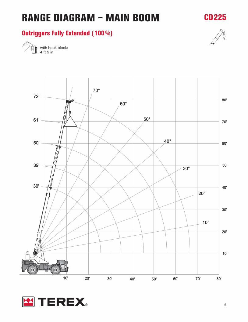
6
CD225
with hook block:4 ft 5 in
RANGE DIAGRAM – MAIN BOOMOutriggers Fully Extended (100%)

7
CD225LOAD CHART – MAIN BOOMOutriggers Fully Extended (100%)
Standard ASMEB30.5
10
12
15
20
25
30
35
40
45
50
55
60
65
50,000
41,600
34,400
21,200
13,700
43,300
39,000
34,000
21,800
14,500
10,300
36,800
31,900
22,000
14,800
10,700
8,000
6,100
4,700
30,500
22,200
14,900
10,800
8,200
6,400
5,000
3,900
3,000
22,300
15,000
10,900
8,300
6,500
5,200
4,100
3,300
2,600
2,000
10
12
15
20
25
30
35
40
45
50
55
60
65
Notes to lifting capacity Lifting capacities do not exceed 85% of tipping load. Weight of hook blocks and slings is part of the load, and is to be deducted from the capacity ratings. Consult operation manual for further details.
Note: Data published herein is intended as a guide only and shall not be construed to warrant applicability for lifting purposes.Crane operation is subject to the computer charts and operation manual both supplied with the crane.
7,200 lbs 14 ft 6 in (100%) 360°
Boom Length
30 ft
lbs
39 ft
lbs
50 ft
lbs
61 ft
lbs
72 ft
lbsft ft

8
CD225
with hook block:4 ft 5 in
RANGE DIAGRAM – MAIN BOOMWith Jib, 26 ft offset

9
CD225LOAD CHART – MAIN BOOMWith Jib, 26 ft offset
7,200 lbs 14 ft 6 in (100%) 360°Standard ASMEB30.5
Notes to lifting capacity Lifting capacities do not exceed 85% of tipping load. Weight of hook blocks and slings is part of the load, and is to be deducted from the capacity ratings. Consult operation manual for further details.
Note: Data published herein is intended as a guide only and shall not be construed to warrant applicability for lifting purposes.Crane operation is subject to the computer charts and operation manual both supplied with the crane.
ft lbs
26 ft 7 in
29 ft 2 in
31 ft 11 in
36 ft 4 in
40 ft 8 in
45 ft
49 ft 9 in
54 ft 10 in
60 ft 11 in
65 ft 7 in
70 ft 4 in
75 ft 8 in
80 ft 11 in
85 ft 11 in
13,000
11,800
9,700
7,800
6,200
5,200
4,400
3,500
2,800
2,200
1,800
1,400
900
600
26 ft Offsettable Jib
0°
ft lbs
31 ft 11 in
34 ft 11 in
37 ft 10 in
42 ft 6 in
47 ft 1 in
51 ft 5 in
55 ft 6 in
60 ft 8 in
65 ft 5 in
70 ft 1 in
74 ft 5 in
79 ft 1 in
83 ft 9 in
88 ft 1 in
7,700
7,200
6,800
6,400
5,400
4,600
3,700
3,000
2,500
2,000
1,600
1,200
800
500
15°
ft lbs
37 ft 6 in
35 ft 5 in
42 ft 4 in
46 ft 8 in
51 ft
55 ft 1 in
58 ft 11 in
63 ft 3 in
67 ft 9 in
72 ft 3 in
76 ft 2 in
80 ft 5 in
84 ft 6 in
5,000
5,300
5,100
4,900
4,700
3,900
3,300
2,700
2,300
1,900
1,500
1,100
800
30°

10
CD225
with hook block:4 ft 5 in
RANGE DIAGRAM – MAIN BOOMWith Jib, 43 ft offset

11
CD225LOAD CHART – MAIN BOOMWith Jib, 43 ft offset
7,200 lbs 14 ft 6 in (100%) 360°Standard ASMEB30.5
43 ft Offsettable Jib
Notes to lifting capacity Lifting capacities do not exceed 85% of tipping load. Weight of hook blocks and slings is part of the load, and is to be deducted from the capacity ratings. Consult operation manual for further details.
Note: Data published herein is intended as a guide only and shall not be construed to warrant applicability for lifting purposes.Crane operation is subject to the computer charts and operation manual both supplied with the crane.
ft lbs
29 ft 10 in
33 ft 9 in
39 ft 1 in
46 ft 2 in
52 ft 6 in
58 ft 1 in
63 ft 3 in
69 ft 6 in
75 ft 1 in
80 ft 3 in
85 ft
90 ft 6 in
96 ft 3 in
5,000
4,800
4,600
4,300
3,900
3,500
3,200
2,600
2,100
1,600
1,300
900
600
0°
ft lbs
33 ft 7 in
39 ft 7 in
45 ft 5 in
52 ft 9 in
58 ft 11 in
64 ft 6 in
69 ft 5 in
75 ft 3 in
80 ft 6 in
85 ft 3 in
89 ft 7 in
94 ft 6 in
99 ft 7 in
3,300
3,100
2,900
2,700
2,500
2,400
2,300
2,200
1,800
1,400
1,100
800
500
15°
ft lbs
47 ft 2 in
51 ft 5 in
55 ft 3 in
60 ft 9 in
65 ft 6 in
69 ft 11 in
74 ft
79 ft 1 in
83 ft 9 in
87 ft 11 in
91 ft 10 in
96 ft 2 in
101 ft
2,400
2,300
2,300
2,200
2,200
2,100
2,100
2,100
1,700
1,300
1,000
700
500
30°

12
CD225
with hook block:4 ft 5 in
RANGE DIAGRAM – MAIN BOOMOn Tires
CD225 usa 10/10 :DB 20.10.2010 6:24 Uhr Seite 12

13
CD225
Notes to lifting capacity Lifting capacities do not exceed 85% of tipping load. Weight of hook blocks and slings is part of the load, and is to be deducted from the capacity ratings. Consult operation manual for further details.
Note: Data published herein is intended as a guide only and shall not be construed to warrant applicability for lifting purposes.Crane operation is subject to the computer charts and operation manual both supplied with the crane.
360°
LOAD CHART – MAIN BOOMOn Tires
7,200 lbsOn tires20.5 x 25-24 PR
Standard ASMEB30.5
10
12
15
20
25
30
35
40
45
50
55
60
65
30
30
39
39
50
50
50
61
61
61
72
72
72
BoomTravel Speed
Boom straight over front
Radius Length
18,600
14,800
11,100
6,400
4,100
2,800
2,000
1,200
700
35,800
30,400
22,200
12,600
8,900
6,600
4,900
3,800
2,800
2,200
1,700
1,200
900
0 mph Creep
25,700
22,100
18,000
12,600
8,900
6,600
4,900
3,800
2,800
2,200
1,700
1,200
900
2.5 mph
ft ft lbs lbs lbs

14
CD225TECHNICAL DESCRIPTION
Boom
Standard configuration:
3 sections hydraulic actuated boom
Full power mechanically synchronized
Min. / Max. 30 ft / 72 ft
Boom elevation angle range (min. / max.) -4° / 76°
Optional configuration:
One section jib 26 ftOffset 0, 15 and 30 degreesMaximum tip height 103 ft
Two section jib 26 ft to 43 ftOffset 0, 15 and 30 degreesMaximum tip height 121 ft
Hoist, Rope and Hook
Standard configuration:
Grooved drumStorage capacity 570 ft
Two speed ratiosWithout load in 5th layer (low range / high range) 227 ft/min / 364 ft/minWithout load in 1st layer (low range / high range) 157 ft/min / 252 ft/min
6 x 19 IWRC XIPS, right regular lay, preformed
5/8 in
455 ft
Max. line pull; 1st layer low-range 12,510 lbsMax. line pull permissible 9,000 lbs

15
CD225TECHNICAL DESCRIPTION
Optional configuration:
Hook and ball 239 lbs2 sheaves 680 lbs3 sheaves 660 lbs4 sheaves 660 lbs
Grooved drumStorage capacity 570 ft
Without load in 5th layer (low range / high range) 227 ft/min / 364 ft/minWithout load in 1st layer (low range / high range) 157 ft/min / 252 ft/min
Rotation resistant compacted strand 18 x 19 or 19 x 19
5/8 in
455 ft
Minimum breaking strength 35,800 lbsMax. line pull permissible 9,000 lbs
Superstructure
Standard configuration:
Non stop 360ºMaximum rotation speed without load 3 rpm
Hydraulic motorPlanetary reducer
360º house lockManually actuated by foot pedal
Cab, Controls, Operator aids and Load limiter / Load indicator
Standard configuration:
Rubber floor matTinted safety glass Six way adjustable seat
Armrest mounted dual axis electro-proportional joysticksSteering wheel column with gear selector on the left and directional light selector on the rightDashboard mounted switches for outrigger operation
Graphic interface for load indicator

16
CD225TECHNICAL DESCRIPTION
Optional configuration:
Hydraulic powered air conditionerHydraulic powered heaterWork lightsRotating beacon
Carrier, Engine, Drive-line and Hydraulic system
Standard configuration:
Hydraulic, independent extension:Diameter of outrigger pads 24 inArea of outrigger pads 452 in2
Cummins QSB4.5 4 cylindersRated power 130 hp @ 2,300 rpmMaximum gross torque 459 ft·lb @ 1,500 rpmIntake: turbocharger with intercoolerFuel type DieselFuel tank capacity 50 gallons
6 x 6 powershift transmission with integral torque converterFull time 4WD (Four-Wheel Drive)Rigid mounted front axleOscillating rear axleDifferential lock on front axle and rear axleRear axle oscillation lock – manual or automatic actuationAir-over-hydraulic disc brakesParking brake on front axleHydraulic oil cooler on carrier
Hydraulic power steeringFront wheel steeringFour wheel steering concentricFour wheel steering crabOptional rear wheel steering package
Hydraulic Pumps:
Tandem pumps:Boom lift / Telescope 30 gal/min @ 3,500 psiPower steering / Outriggers and Swing 21 gal/min @ 2,500 psi
Single pump:Main and auxiliary hoist pump 41 gal/min @ 3,500 psi
Hydraulic oil reservoir capacity 94 gallonsHydraulic oil suction filter 250 micronsHydraulic oil return filter 5 microns

17
CD225TECHNICAL DESCRIPTION
Vehicle performance
Standard configuration:
Max. in 1st gear (low range) 112 %Max. in 3rd gear (high range) 3.8 %
Max. (6th gear) 24.5 mph
Tires
Standard configuration:
Wide tread earth mover pattern (E3) 20.5 x 25-20 PR
Optional configuration:
Industrial pattern 14.00 x 24-20 PR

CD225
www.terexcranes.comEffective Date: October 2010.Product specifications and prices are subject to change without notice or obligation. The photographs and/or drawings in this document are for illustrative purposes only. Refer to the appropriate Operator’s Manual for instructions on the proper use of this equipment. Failure to follow the appropriate Operator’s Manual when using our equipment or to otherwise act irresponsibly may result in serious injury or death. The only warranty applicable to our equipment isthe standard written warranty applicable to the particular product and sale and Terex makes no other warranty, express or implied. Products and services listed may be trademarks, service marks or trade-names of Terex Corporation and/or its subsidiaries in the USA and other countries. All rights are reserved. Terex® is a registered trademark of Terex Corporation in the USA and many other countries.
Copyright 2010 Terex Corporation
Terex Cranes, Global Marketing, Dinglerstraße 24, 66482 Zweibrücken, GermanyTel. +49 (0) 6332 830, Email: [email protected], www.terexcranes.com
Brochure Reference: TC-DS-I-E-CD225-10/10