cable carriers for round cable -beam supported · cable carriers for round cable 4-13 cable saddles...
TRANSCRIPT
8C | EN 2019
CABLE CARRIERS FOR ROUND CABLE-BEAM SUPPORTED
Katalog_8c_Leitungswagen_für_Rundleitungen-Umschlag.indd 1 14.08.2019 12:07:31
VAHLE FESTOON SYSTEMS
2
Contents Page
General Information 2
Questionnaire 3
Cable Carriers for Round Cable 4-13
Cable Saddles for Round Cable 14-15
Cable Loop Clamps for Round Cable 16
Tow Rope Assemblies 17
Page
Spare Parts 18
Typical Application and How to Order 19
Installation Information 20
How to determine: Storage Distance,Cable Length, Number of Carriers 21
Cable Loop Graphs 22-24
Application photos 21, 25
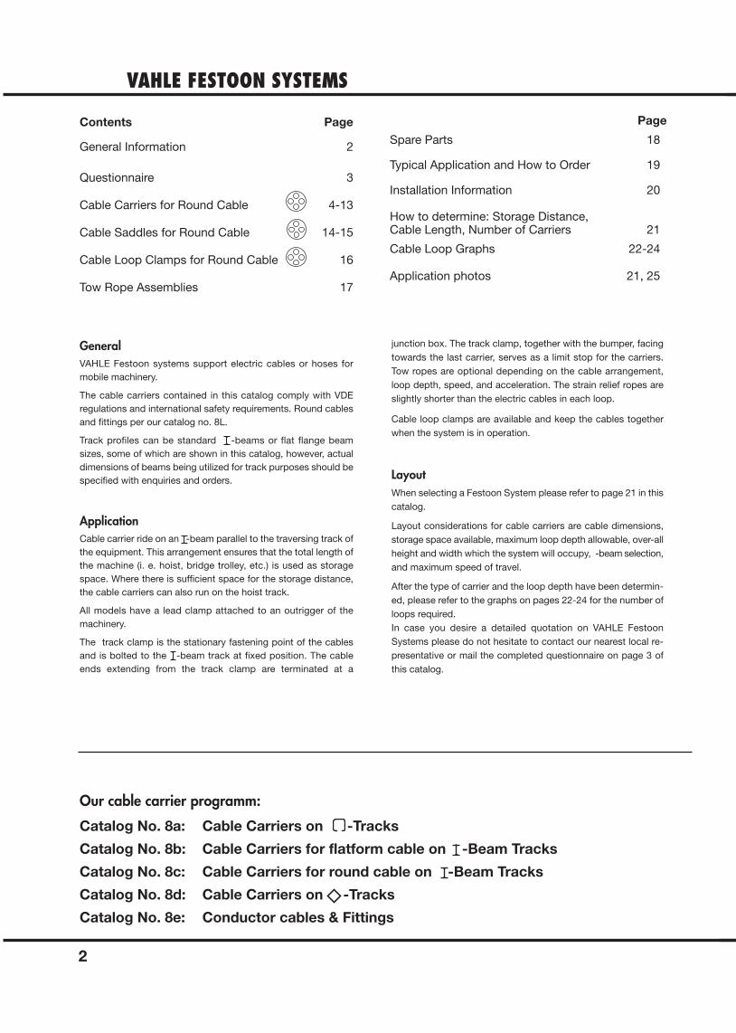
GeneralVAHLE Festoon systems support electric cables or hoses for mobile machinery.
The cable carriers contained in this catalog comply with VDE regulations and international safety requirements. Round cablesand fittings per our catalog no. 8L.
Track profiles can be standard -beams or flat flange beam sizes, some of which are shown in this catalog, however, actualdimensions of beams being utilized for track purposes should bespecified with enquiries and orders.
ApplicationCable carrier ride on an -beam parallel to the traversing track ofthe equipment. This arrangement ensures that the total length ofthe machine (i. e. hoist, bridge trolley, etc.) is used as storagespace. Where there is sufficient space for the storage distance,the cable carriers can also run on the hoist track.
All models have a lead clamp attached to an outrigger of the machinery.
The track clamp is the stationary fastening point of the cablesand is bolted to the -beam track at fixed position. The cableends extending from the track clamp are terminated at a
junction box. The track clamp, together with the bumper, facingtowards the last carrier, serves as a limit stop for the carriers.Tow ropes are optional depending on the cable arrangement,loop depth, speed, and acceleration. The strain relief ropes areslightly shorter than the electric cables in each loop.
Cable loop clamps are available and keep the cables togetherwhen the system is in operation.
LayoutWhen selecting a Festoon System please refer to page 21 in thiscatalog.
Layout considerations for cable carriers are cable dimensions,storage space available, maximum loop depth allowable, over-allheight and width which the system will occupy, -beam selection,and maximum speed of travel.
After the type of carrier and the loop depth have been determin-ed, please refer to the graphs on pages 22-24 for the number ofloops required.In case you desire a detailed quotation on VAHLE Festoon Systems please do not hesitate to contact our nearest local re-presentative or mail the completed questionnaire on page 3 ofthis catalog.
Our cable carrier programm:
Catalog No. 8a: Cable Carriers on -Tracks
Catalog No. 8b: Cable Carriers for flatform cable on -Beam Tracks
Catalog No. 8c: Cable Carriers for round cable on -Beam Tracks
Catalog No. 8d: Cable Carriers on -Tracks
Catalog No. 8e: Conductor cables & Fittings
QUESTIONNAIRE
3
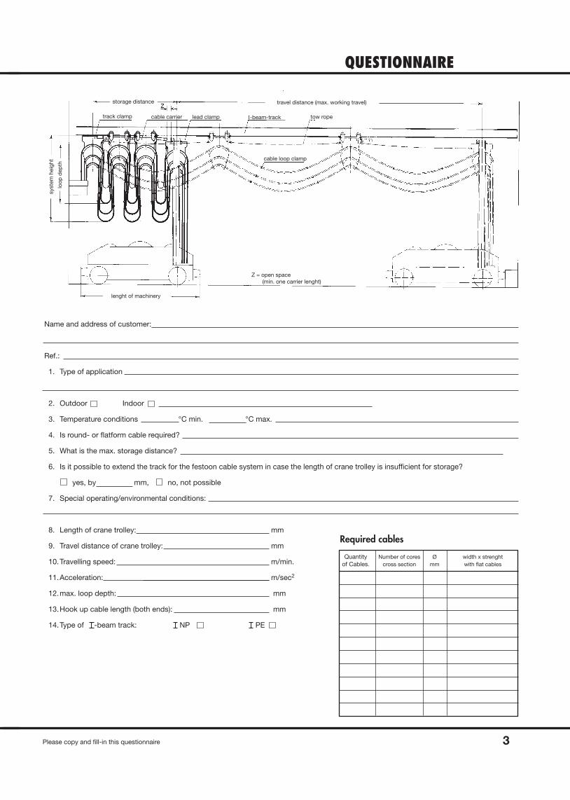
storage distance
track clamp cable carrier lead clamp I-beam-track
travel distance (max. working travel)
tow rope
cable loop clamp
loo
p d
ep
th
syste
m h
eig
ht
lenght of machinery
Z = open space
(min. one carrier lenght)
Name and address of customer:
Ref.:
1. Type of application
2. Outdoor Indoor
3. Temperature conditions °C min. °C max.
4. Is round- or flatform cable required?
5. What is the max. storage distance?
6. Is it possible to extend the track for the festoon cable system in case the length of crane trolley is insufficient for storage?
yes, by mm, no, not possible
7. Special operating/environmental conditions:
8. Length of crane trolley: mm
9. Travel distance of crane trolley: mm
10.Travelling speed: m/min.
11.Acceleration: m/sec2
12.max. loop depth: mm
13.Hook up cable length (both ends): mm
14.Type of -beam track: NP PE
Quantity Number of cores Ø width x strenghtof Cables. cross section mm with flat cables
Required cables
Please copy and fill-in this questionnaire
CABLE CARRIERS W 25 R, W 26 R, W 30 RNormal- and europe profile
4
Engineering data
(for calculation of
storage distance)
joint
profile
cable
(for calculation of
storage distance)
joint
profile
cable
joint
profile
cab
le
joint
profile
cable Ø
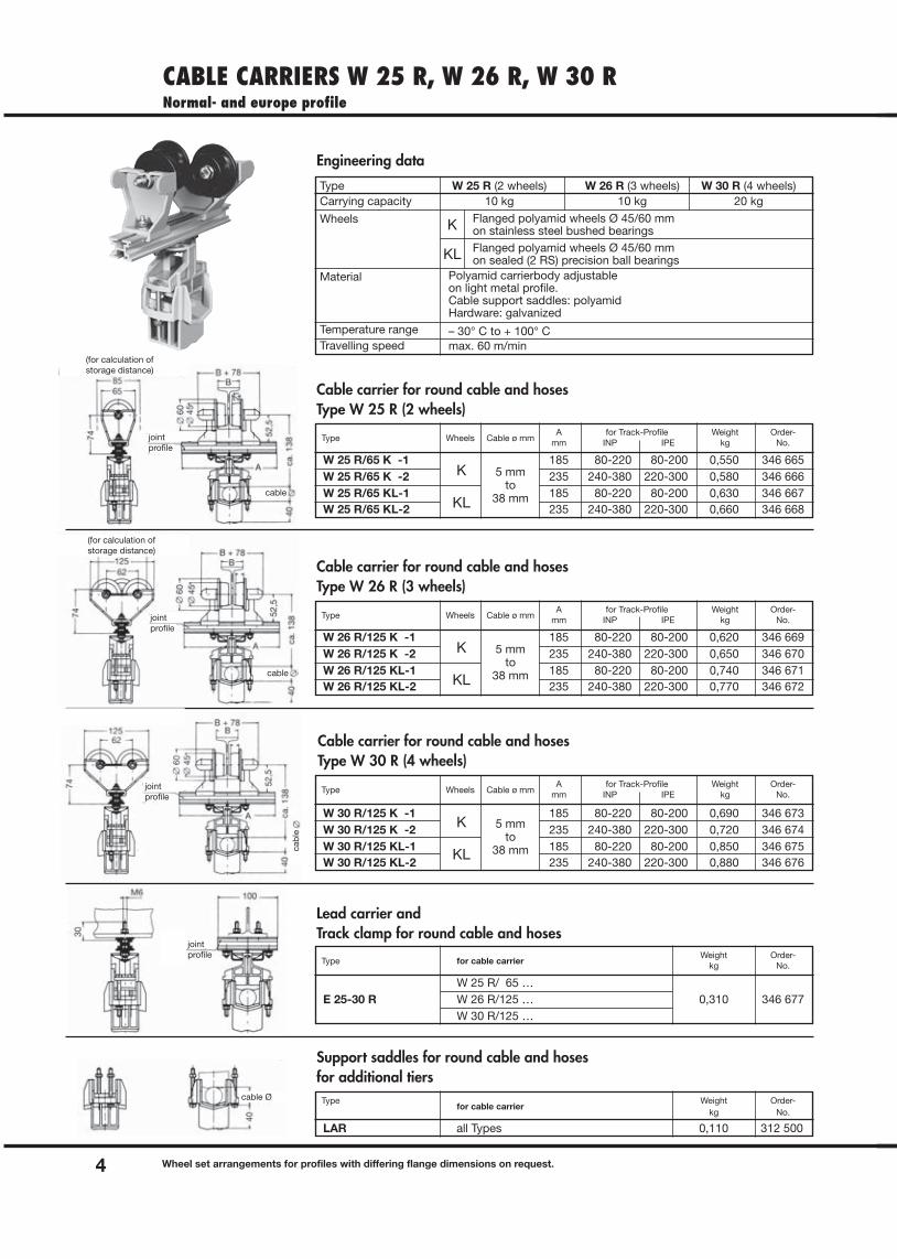
Type W 25 R (2 wheels) W 26 R (3 wheels) W 30 R (4 wheels)Carrying capacity 10 kg 10 kg 20 kg
Wheels
Material
Temperature rangeTravelling speed
Flanged polyamid wheels Ø 45/60 mmon stainless steel bushed bearingsFlanged polyamid wheels Ø 45/60 mmon sealed (2 RS) precision ball bearings
Polyamid carrierbody adjustableon light metal profile.Cable support saddles: polyamidHardware: galvanized
– 30° C to + 100° Cmax. 60 m/min
K
KL
K
KL
K
KL
K
KL
5 mmto
38 mm
5 mmto
38 mm
5 mmto
38 mm
Cable carrier for round cable and hosesType W 25 R (2 wheels)
Type Wheels Cable ø mmA for Track-Profile Weight Order-
mm INP IPE kg No.
W 25 R/65 K -1 185 80-220 80-200 0,550 346 665W 25 R/65 K -2 235 240-380 220-300 0,580 346 666W 25 R/65 KL-1 185 80-220 80-200 0,630 346 667W 25 R/65 KL-2 235 240-380 220-300 0,660 346 668
Cable carrier for round cable and hosesType W 26 R (3 wheels)
Type Wheels Cable ø mmA for Track-Profile Weight Order-
mm INP IPE kg No.
W 26 R/125 K -1 185 80-220 80-200 0,620 346 669W 26 R/125 K -2 235 240-380 220-300 0,650 346 670W 26 R/125 KL-1 185 80-220 80-200 0,740 346 671W 26 R/125 KL-2 235 240-380 220-300 0,770 346 672
Cable carrier for round cable and hosesType W 30 R (4 wheels)
Lead carrier and Track clamp for round cable and hoses
Type Wheels Cable ø mmA for Track-Profile Weight Order-
mm INP IPE kg No.
Type for cable carrierWeight Order-
kg No.
W 25 R/ 65 …E 25-30 R W 26 R/125 … 0,310 346 677
W 30 R/125 …
Support saddles for round cable and hosesfor additional tiers
Typefor cable carrier
Weight Order-kg No.
LAR all Types 0,110 312 500
W 30 R/125 K -1 185 80-220 80-200 0,690 346 673W 30 R/125 K -2 235 240-380 220-300 0,720 346 674W 30 R/125 KL-1 185 80-220 80-200 0,850 346 675W 30 R/125 KL-2 235 240-380 220-300 0,880 346 676
Wheel set arrangements for profiles with differing flange dimensions on request.
CABLE CARRIERS W 45 FR
5
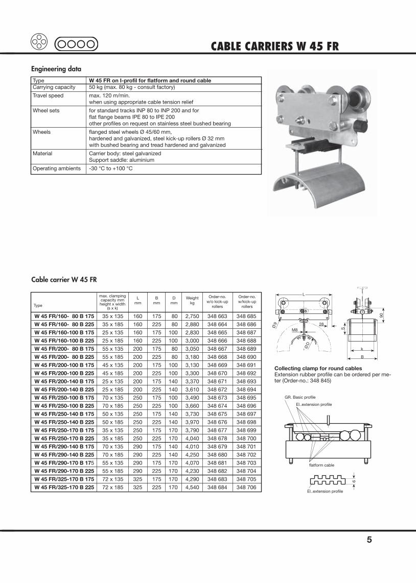
Engineering data
Type W 45 FR on I-profil for flatform and round cableCarrying capacity 50 kg (max. 80 kg - consult factory)
Travel speed max. 120 m/min. when using appropriate cable tension relief
Wheel sets for standard tracks INP 80 to INP 200 and forflat flange beams IPE 80 to IPE 200other profiles on request on stainless steel bushed bearing
Wheels flanged steel wheels Ø 45/60 mm, hardened and galvanized, steel kick-up rollers Ø 32 mm with bushed bearing and tread hardened and galvanized
Material Carrier body: steel galvanizedSupport saddle: aluminium
Operating ambients -30 °C to +100 °C
Cable carrier W 45 FR
Type
Order-no.w/o kick-up
rollers
Order-no.w/kick-up
rollers
Lmm
Bmm
Dmm
Weightkg
W 45 FR/160- 80 B 175 35 x 135 160 175 80 2,750 348 663 348 685
W 45 FR/160- 80 B 225 35 x 185 160 225 80 2,880 348 664 348 686
W 45 FR/160-100 B 175 25 x 135 160 175 100 2,830 348 665 348 687
W 45 FR/160-100 B 225 25 x 185 160 225 100 3,000 348 666 348 688
W 45 FR/200- 80 B 175 55 x 135 200 175 80 3,050 348 667 348 689
W 45 FR/200- 80 B 225 55 x 185 200 225 80 3,180 348 668 348 690
W 45 FR/200-100 B 175 45 x 135 200 175 100 3,130 348 669 348 691
W 45 FR/200-100 B 225 45 x 185 200 225 100 3,300 348 670 348 692
W 45 FR/200-140 B 175 25 x 135 200 175 140 3,370 348 671 348 693
W 45 FR/200-140 B 225 25 x 185 200 225 140 3,610 348 672 348 694
W 45 FR/250-100 B 175 70 x 135 250 175 100 3,490 348 673 348 695
W 45 FR/250-100 B 225 70 x 185 250 225 100 3,660 348 674 348 696
W 45 FR/250-140 B 175 50 x 135 250 175 140 3,730 348 675 348 697
W 45 FR/250-140 B 225 50 x 185 250 225 140 3,970 348 676 348 698
W 45 FR/250-170 B 175 35 x 135 250 175 170 3,790 348 677 348 699
W 45 FR/250-170 B 225 35 x 185 250 225 170 4,040 348 678 348 700
W 45 FR/290-140 B 175 70 x 135 290 175 140 4,010 348 679 348 701
W 45 FR/290-140 B 225 70 x 185 290 225 140 4,250 348 680 348 702
W 45 FR/290-170 B 175 55 x 135 290 175 170 4,070 348 681 348 703
W 45 FR/290-170 B 225 55 x 185 290 225 170 4,230 348 682 348 704
W 45 FR/325-170 B 175 72 x 135 325 175 170 4,290 348 683 348 705
W 45 FR/325-170 B 225 72 x 185 325 225 170 4,540 348 684 348 706
L
Ø 9
M828
Ø D
Sk
B
90
GR. Basic profile
El..extension profile
flatform cable
El..extension profile
6
max. clampingcapacity mmheight x width
(s x k)
Collecting clamp for round cablesExtension rubber profile can be ordered per me-ter (Order-no.: 348 845)
CABLE CARRIERS W 45 FR
6
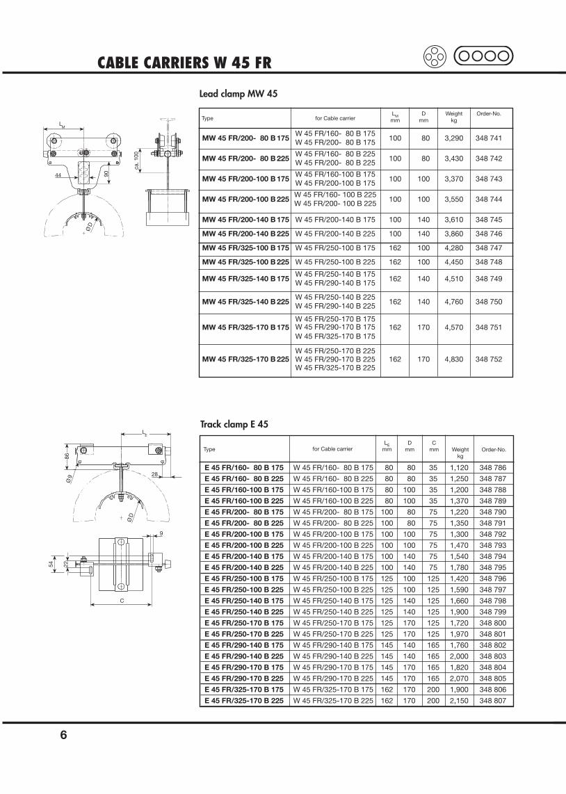
Lead clamp MW 45
Type for Cable carrierLM D Weight Order-No.
mm mm kg
MW 45 FR/200- 80 B 175W 45 FR/160- 80 B 175
100 80 3,290 348 741W 45 FR/200- 80 B 175
MW 45 FR/200- 80 B 225W 45 FR/160- 80 B 225
100 80 3,430 348 742W 45 FR/200- 80 B 225
MW 45 FR/200-100 B 175W 45 FR/160-100 B 175
100 100 3,370 348 743W 45 FR/200-100 B 175
MW 45 FR/200-100 B 225W 45 FR/160- 100 B 225
100 100 3,550 348 744W 45 FR/200- 100 B 225
MW 45 FR/200-140 B 175 W 45 FR/200-140 B 175 100 140 3,610 348 745
MW 45 FR/200-140 B 225 W 45 FR/200-140 B 225 100 140 3,860 348 746
MW 45 FR/325-100 B 175 W 45 FR/250-100 B 175 162 100 4,280 348 747
MW 45 FR/325-100 B 225 W 45 FR/250-100 B 225 162 100 4,450 348 748
MW 45 FR/325-140 B 175W 45 FR/250-140 B 175
162 140 4,510 348 749W 45 FR/290-140 B 175
MW 45 FR/325-140 B 225W 45 FR/250-140 B 225
162 140 4,760 348 750W 45 FR/290-140 B 225
MW 45 FR/325-170 B 175W 45 FR/250-170 B 175
162 170 4,570 348 751W 45 FR/290-170 B 175W 45 FR/325-170 B 175
MW 45 FR/325-170 B 225W 45 FR/250-170 B 225
162 170 4,830 348 752W 45 FR/290-170 B 225W 45 FR/325-170 B 225
Track clamp E 45
Type for Cable carrier Order-No.LE
mmD
mmC
mm Weightkg
E 45 FR/160- 80 B 175 W 45 FR/160- 80 B 175 80 80 35 1,120 348 786
E 45 FR/160- 80 B 225 W 45 FR/160- 80 B 225 80 80 35 1,250 348 787
E 45 FR/160-100 B 175 W 45 FR/160-100 B 175 80 100 35 1,200 348 788
E 45 FR/160-100 B 225 W 45 FR/160-100 B 225 80 100 35 1,370 348 789
E 45 FR/200- 80 B 175 W 45 FR/200- 80 B 175 100 80 75 1,220 348 790
E 45 FR/200- 80 B 225 W 45 FR/200- 80 B 225 100 80 75 1,350 348 791
E 45 FR/200-100 B 175 W 45 FR/200-100 B 175 100 100 75 1,300 348 792
E 45 FR/200-100 B 225 W 45 FR/200-100 B 225 100 100 75 1,470 348 793
E 45 FR/200-140 B 175 W 45 FR/200-140 B 175 100 140 75 1,540 348 794
E 45 FR/200-140 B 225 W 45 FR/200-140 B 225 100 140 75 1,780 348 795
E 45 FR/250-100 B 175 W 45 FR/250-100 B 175 125 100 125 1,420 348 796
E 45 FR/250-100 B 225 W 45 FR/250-100 B 225 125 100 125 1,590 348 797
E 45 FR/250-140 B 175 W 45 FR/250-140 B 175 125 140 125 1,660 348 798
E 45 FR/250-140 B 225 W 45 FR/250-140 B 225 125 140 125 1,900 348 799
E 45 FR/250-170 B 175 W 45 FR/250-170 B 175 125 170 125 1,720 348 800
E 45 FR/250-170 B 225 W 45 FR/250-170 B 225 125 170 125 1,970 348 801
E 45 FR/290-140 B 175 W 45 FR/290-140 B 175 145 140 165 1,760 348 802
E 45 FR/290-140 B 225 W 45 FR/290-140 B 225 145 140 165 2,000 348 803
E 45 FR/290-170 B 175 W 45 FR/290-170 B 175 145 170 165 1,820 348 804
E 45 FR/290-170 B 225 W 45 FR/290-170 B 225 145 170 165 2,070 348 805
E 45 FR/325-170 B 175 W 45 FR/325-170 B 175 162 170 200 1,900 348 806
E 45 FR/325-170 B 225 W 45 FR/325-170 B 225 162 170 200 2,150 348 807
LM
44 90
Ø D
ca. 1
00
86Ø
9
Ø D
28
9
LE
54 22
C
CABLE CARRIERS W 110Normal- and europe profile
7
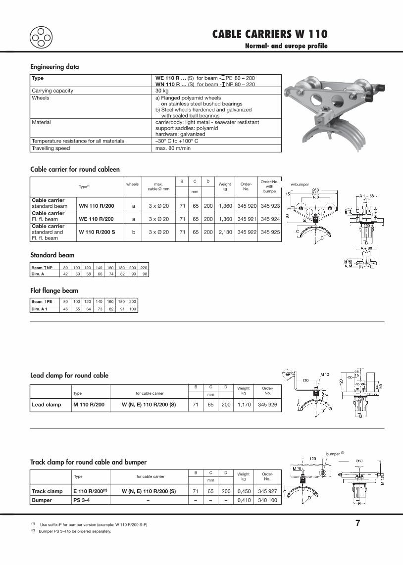
Engineering data
Cable carrier for round cableen
Standard beam
Lead clamp for round cable
Track clamp for round cable and bumper
Flat flange beam
w/bumper
bumper (2)
Type WE 110 R … (S) for beam - PE 80 – 200WN 110 R … (S) for beam - NP 80 – 220
Carrying capacity 30 kgWheels a) Flanged polyamid wheels
on stainless steel bushed bearingsb) Steel wheels hardened and galvanized
with sealed ball bearingsMaterial carrierbody: light metal - seawater restistant
support saddles: polyamidhardware: galvanized
Temperature resistance for all materials –30° C to +100° CTravelling speed max. 80 m/min
Type(1) wheels max.cable Ø mm
mm
B C DWeight
kgOrder-
No.
Order-No.with
bumpe
Cable carrierstandard beam WN 110 R/200 a 3 x Ø 20 71 65 200 1,360 345 920 345 923
WE 110 R/200 a 3 x Ø 20 71 65 200 1,360 345 921 345 924
W 110 R/200 S b 3 x Ø 20 71 65 200 2,130 345 922 345 925
Cable carrierFl. fl. beamCable carrierstandard andFl. fl. beam
Beam NP 80 100 120 140 160 180 200 220
Dim. A 42 50 58 66 74 82 90 98
Beam PE 80 100 120 140 160 180 200
Dim. A 1 46 55 64 73 82 91 100
Type for cable carrier mm
B C D Weightkg
Order-No.
Lead clamp M 110 R/200 W (N, E) 110 R/200 (S) 71 65 200 1,170 345 926
Type for cable carriermm
B C D Weightkg
Order-No..
Track clamp E 110 R/200(2) W (N, E) 110 R/200 (S) 71 65 200 0,450 345 927
Bumper PS 3-4 – – – – 0,410 340 100
(1) Use suffix-P for bumper version (example: W 110 R/200 S-P)(2) Bumper PS 3-4 to be ordered separately.
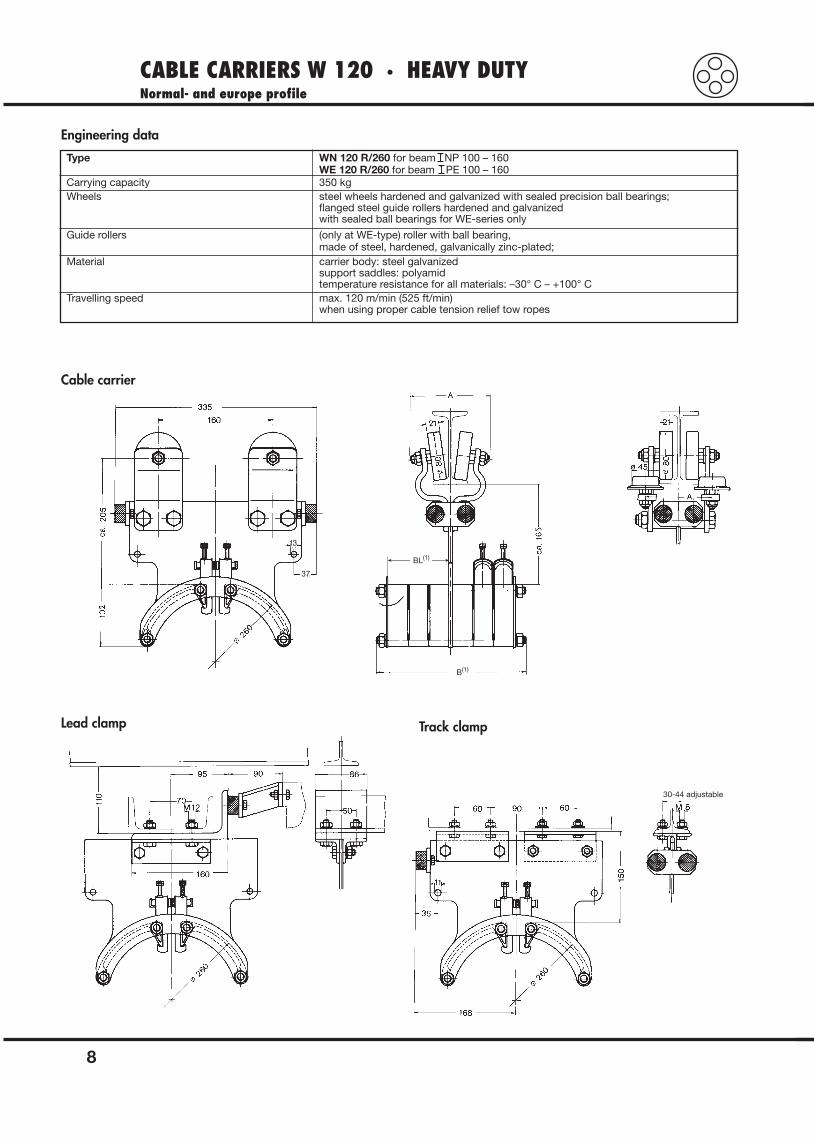
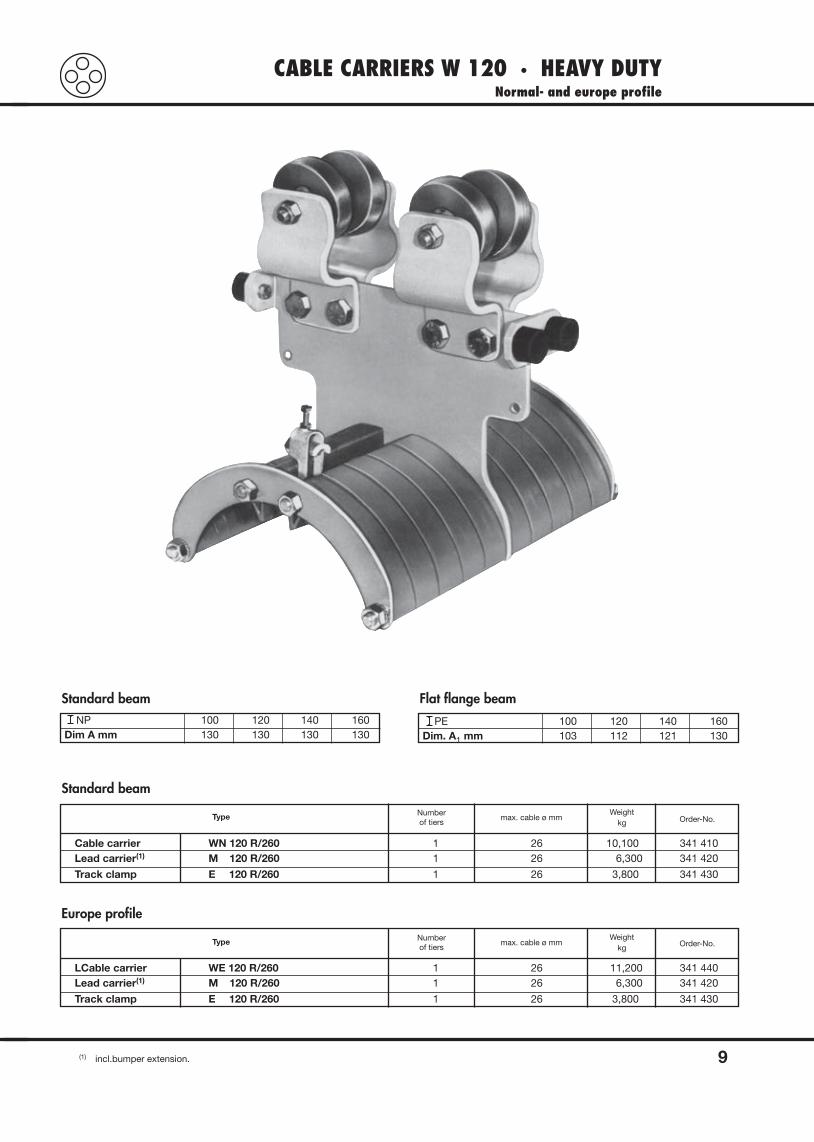
CABLE CARRIERS W 120 · HEAVY DUTYNormal- and europe profile
8
Engineering data
Cable carrier
Lead clamp Track clamp
B(1)
BL(1)
37
13
30-44 adjustable
Type WN 120 R/260 for beam NP 100 – 160WE 120 R/260 for beam PE 100 – 160
Carrying capacity 350 kgWheels steel wheels hardened and galvanized with sealed precision ball bearings;
flanged steel guide rollers hardened and galvanizedwith sealed ball bearings for WE-series only
Guide rollers (only at WE-type) roller with ball bearing,made of steel, hardened, galvanically zinc-plated;
Material carrier body: steel galvanizedsupport saddles: polyamidtemperature resistance for all materials: –30° C – +100° C
Travelling speed max. 120 m/min (525 ft/min)when using proper cable tension relief tow ropes
CABLE CARRIERS W 120 · HEAVY DUTYNormal- and europe profile
9(1) incl.bumper extension.
Standard beam
Standard beam
NP 100 120 140 160Dim A mm 130 130 130 130
Flat flange beam
PE 100 120 140 160Dim. A1 mm 103 112 121 130
Type Numberof tiers
max. cable ø mmWeight
kg Order-No.
Cable carrier WN 120 R/260 1 26 10,100 341 410Lead carrier(1) M 120 R/260 1 26 6,300 341 420
Track clamp E 120 R/260 1 26 3,800 341 430
Europe profile
Type Numberof tiers
max. cable ø mmWeight
kg Order-No.
LCable carrier WE 120 R/260 1 26 11,200 341 440Lead carrier(1) M 120 R/260 1 26 6,300 341 420
Track clamp E 120 R/260 1 26 3,800 341 430
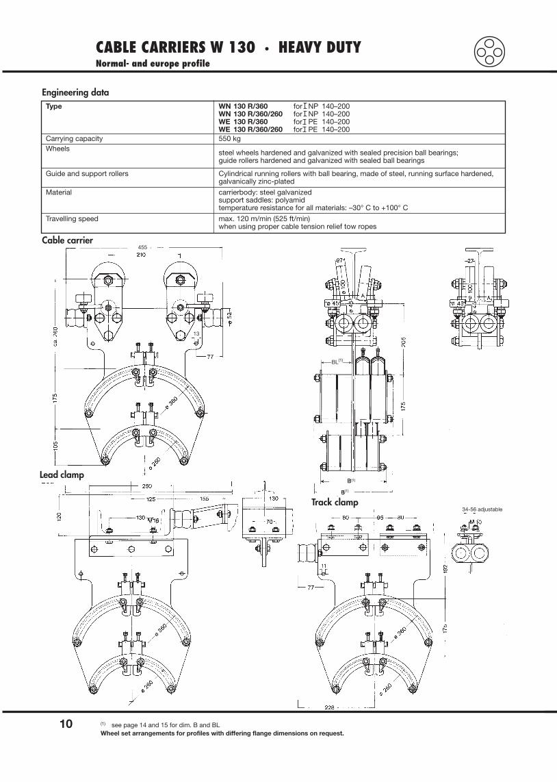
CABLE CARRIERS W 130 · HEAVY DUTYNormal- and europe profile
10 (1) see page 14 and 15 for dim. B and BLWheel set arrangements for profiles with differing flange dimensions on request.
Engineering dataType WN 130 R/360 for NP 140–200
WN 130 R/360/260 for NP 140–200WE 130 R/360 for PE 140–200 WE 130 R/360/260 for PE 140–200
Carrying capacity 550 kgWheels steel wheels hardened and galvanized with sealed precision ball bearings;
guide rollers hardened and galvanized with sealed ball bearings
Guide and support rollers Cylindrical running rollers with ball bearing, made of steel, running surface hardened,galvanically zinc-plated
Material carrierbody: steel galvanizedsupport saddles: polyamidtemperature resistance for all materials: –30° C to +100° C
Travelling speed max. 120 m/min (525 ft/min)when using proper cable tension relief tow ropes
Cable carrier
Lead clamp
Track clamp34-56 adjustable
455
(1)
(1)
13
BL(1)
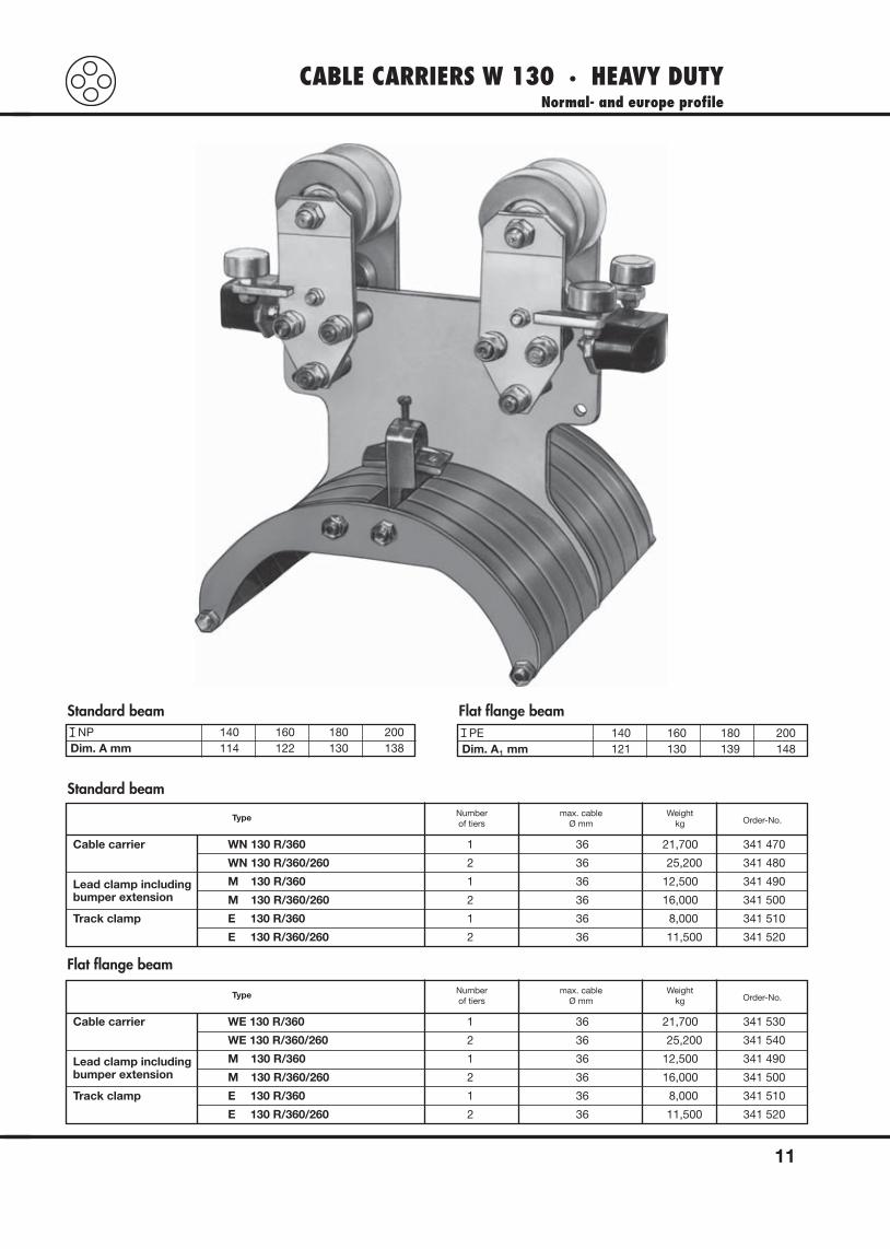
CABLE CARRIERS W 130 · HEAVY DUTYNormal- and europe profile
11
Standard beamNP 140 160 180 200
Dim. A mm 114 122 130 138
Flat flange beamPE 140 160 180 200
Dim. A1 mm 121 130 139 148
Standard beam
Flat flange beam
Type Numberof tiers
max. cableØ mm
Weightkg Order-No.
Cable carrier WN 130 R/360 1 36 21,700 341 470
WN 130 R/360/260 2 36 25,200 341 480
Lead clamp including M 130 R/360 1 36 12,500 341 490bumper extension M 130 R/360/260 2 36 16,000 341 500
Track clamp E 130 R/360 1 36 8,000 341 510
E 130 R/360/260 2 36 11,500 341 520
Type Numberof tiers
max. cableØ mm
Weightkg Order-No.
Cable carrier WE 130 R/360 1 36 21,700 341 530
WE 130 R/360/260 2 36 25,200 341 540
Lead clamp including M 130 R/360 1 36 12,500 341 490bumper extension M 130 R/360/260 2 36 16,000 341 500
Track clamp E 130 R/360 1 36 8,000 341 510
E 130 R/360/260 2 36 11,500 341 520
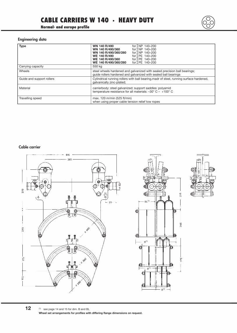
CABLE CARRIERS W 140 · HEAVY DUTYNormal- and europe profile
12
Engineering data
Type WN 140 R/490 for NP 140–200WN 140 R/490/360 for NP 140–200WN 140 R/490/360/260 for NP 140–200WE 140 R/490 for PE 140–200 WE 140 R/490/360 for PE 140–200WE 140 R/490/360/260 for PE 140–200
Carrying capacity 550 kg
Wheels steel wheels hardened and galvanized with sealed precision ball bearings;guide rollers hardened and galvanized with sealed ball bearings
Guide and support rollers Cylindrical running rollers with ball bearing,madr of steel, running surface hardened,galvanically zinc-plated;
Material carrierbody: steel galvanized; support saddles: polyamidtemperature resistance for all materials: –30° C – +100° C
Travelling speed max. 120 m/min (525 ft/min)when using proper cable tension relief tow ropes
(1) see page 14 and 15 for dim. B and BLWheel set arrangements for profiles with differing flange dimensions on request.
BL(1)
B(1)
B(1)
B(1)
13
Cable carrier
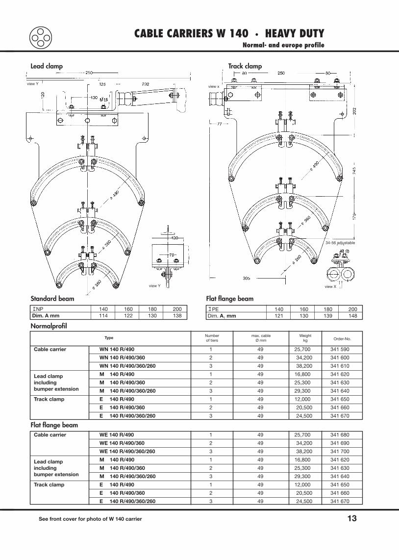
CABLE CARRIERS W 140 · HEAVY DUTYNormal- and europe profile
13See front cover for photo of W 140 carrier
view Yview x
view Xview Y
34-56 adjustable
Lead clamp Track clamp
Standard beamNP 140 160 180 200
Dim. A mm 114 122 130 138
Flat flange beamPE 140 160 180 200
Dim. A1 mm 121 130 139 148
Normalprofil
Flat flange beam
Type Numberof tiers
max. cableØ mm
Weightkg Order-No.
Cable carrier WN 140 R/490 1 49 25,700 341 590
WN 140 R/490/360 2 49 34,200 341 600
WN 140 R/490/360/260 3 49 38,200 341 610
Lead clamp M 140 R/490 1 49 16,800 341 620
including M 140 R/490/360 2 49 25,300 341 630bumper extension M 140 R/490/360/260 3 49 29,300 341 640
Track clamp E 140 R/490 1 49 12,000 341 650
E 140 R/490/360 2 49 20,500 341 660
E 140 R/490/360/260 3 49 24,500 341 670
Cable carrier WE 140 R/490 1 49 25,700 341 680
WE 140 R/490/360 2 49 34,200 341 690
WE 140 R/490/360/260 3 49 38,200 341 700
Lead clamp M 140 R/490 1 49 16,800 341 620
including M 140 R/490/360 2 49 25,300 341 630bumper extension M 140 R/490/360/260 3 49 29,300 341 640
Track clamp E 140 R/490 1 49 12,000 341 650
E 140 R/490/360 2 49 20,500 341 660
E 140 R/490/360/260 3 49 24,500 341 670
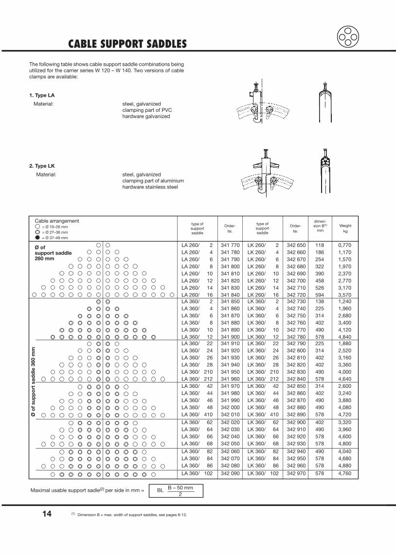
CABLE SUPPORT SADDLES
14 (1) Dimension B = max. width of support saddles, see pages 8-13.
The following table shows cable support saddle combinations beingutilized for the carrier series W 120 – W 140. Two versions of cableclamps are available:
1. Type LA
Material: steel, galvanizedclamping part of PVChardware galvanized
2. Type LK
Material: steel, galvanizedclamping part of aluminiumhardware stainless steel
Cable arrangement= Ø 10–26 mm= Ø 27–36 mm= Ø 37–49 mm
Ø of support saddle260 mm
Ø o
f su
pp
ort
sad
dle
360
mm
type ofsupport saddle
Order-Nr.
type ofsupportsaddle
Order-Nr.
dimen-sion B(1)
mmWeight
kg
LA 260/ 2 341 770 LK 260/ 2 342 650 118 0,770LA 260/ 4 341 780 LK 260/ 4 342 660 186 1,170LA 260/ 6 341 790 LK 260/ 6 342 670 254 1,570LA 260/ 8 341 800 LK 260/ 8 342 680 322 1,970LA 260/ 10 341 810 LK 260/ 10 342 690 390 2,370LA 260/ 12 341 820 LK 260/ 12 342 700 458 2,770LA 260/ 14 341 830 LK 260/ 14 342 710 526 3,170LA 260/ 16 341 840 LK 260/ 16 342 720 594 3,570LA 360/ 2 341 850 LK 360/ 2 342 730 138 1,240LA 360/ 4 341 860 LK 360/ 4 342 740 225 1,960LA 360/ 6 341 870 LK 360/ 6 342 750 314 2,680LA 360/ 8 341 880 LK 360/ 8 342 760 402 3,400LA 360/ 10 341 890 LK 360/ 10 342 770 490 4,120LA 360/ 12 341 900 LK 360/ 12 342 780 578 4,840LA 360/ 22 341 910 LK 360/ 22 342 790 225 1,880LA 360/ 24 341 920 LK 360/ 24 342 800 314 2,520LA 360/ 26 341 930 LK 360/ 26 342 810 402 3,160LA 360/ 28 341 940 LK 360/ 28 342 820 402 3,360LA 360/ 210 341 950 LK 360/ 210 342 830 490 4,000LA 360/ 212 341 960 LK 360/ 212 342 840 578 4,640LA 360/ 42 341 970 LK 360/ 42 342 850 314 2,600LA 360/ 44 341 980 LK 360/ 44 342 860 402 3,240LA 360/ 46 341 990 LK 360/ 46 342 870 490 3,880LA 360/ 48 342 000 LK 360/ 48 342 880 490 4,080LA 360/ 410 342 010 LK 360/ 410 342 890 578 4,720
LA 360/ 62 342 020 LK 360/ 62 342 900 402 3,320LA 360/ 64 342 030 LK 360/ 64 342 910 490 3,960LA 360/ 66 342 040 LK 360/ 66 342 920 578 4,600LA 360/ 68 342 050 LK 360/ 68 342 930 578 4,800
LA 360/ 82 342 060 LK 360/ 82 342 940 490 4,040LA 360/ 84 342 070 LK 360/ 84 342 950 578 4,680LA 360/ 86 342 080 LK 360/ 86 342 960 578 4,880
LA 360/ 102 342 090 LK 360/ 102 342 970 578 4,760
Maximal usable support sadle(2) per side in mm = BL B – 50 mm2
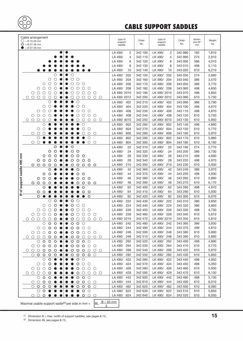
CABLE SUPPORT SADDLES
15(1) Dimension B = max. width of support saddles, see pages 8-13.(2) Dimension BL see pages 8-13.
Cable arrangement= Ø 10–26 mm= Ø 27–36 mm= Ø 37–49 mm
Ø o
f su
pp
ort
sad
dle
490
mm
type ofsupport saddle
Order-No.
type ofsupport saddle
Order-No.
dimen-sion B(1
mm
Weightkg
LA 490/ 2 342 100 LK 490/ 2 342 980 162 1,810LA 490/ 4 342 110 LK 490/ 4 342 990 274 2,910LA 490/ 6 342 120 LK 490/ 6 343 000 386 4,010LA 490/ 8 342 130 LK 490/ 8 343 010 498 5,110LA 490/ 10 342 140 LK 490/ 10 343 020 610 6,210
LA 490/ 202 342 150 LK 490/ 202 343 030 274 2,690LA 490/ 204 342 160 LK 490/ 204 343 040 386 3,570LA 490/ 206 342 170 LK 490/ 206 343 050 386 3,770LA 490/ 208 342 180 LK 490/ 208 343 060 498 4,650LA 490/ 2010 342 190 LK 490/ 2010 343 070 498 4,850LA 490/ 2012 342 200 LK 490/ 2012 343 080 610 5,730
LA 490/ 402 342 210 LK 490/ 402 343 090 386 3,790LA 490/ 404 342 220 LK 490/ 404 343 100 498 4,670LA 490/ 406 342 230 LK 490/ 406 343 110 498 4,870LA 490/ 408 342 240 LK 490/ 408 343 120 610 5,750LA 490/ 4010 342 250 LK 490/ 4010 343 130 610 5,950
LA 490/ 602 342 260 LK 490/ 602 343 140 498 4,890LA 490/ 604 342 270 LK 490/ 604 343 150 610 5,770LA 490/ 606 342 280 LK 490/ 606 343 160 610 5,970
LA 490/ 802 342 290 LK 490/ 802 343 170 610 5,990LA 490/ 804 342 300 LK 490/ 804 343 180 610 6,190
LA 490/ 22 342 310 LK 490/ 22 343 190 274 2,770LA 490/ 24 342 320 LK 490/ 24 343 200 386 3,730LA 490/ 26 342 330 LK 490/ 26 343 210 498 4,690LA 490/ 28 342 340 LK 490/ 28 343 220 498 4,970LA 490/ 210 342 350 LK 490/ 210 343 230 610 5,930
LA 490/ 42 342 360 LK 490/ 42 343 240 386 3,970LA 490/ 44 342 370 LK 490/ 44 343 250 498 4,930LA 490/ 46 342 380 LK 490/ 46 343 260 610 5,890LA 490/ 48 342 390 LK 490/ 48 343 270 610 6,170
LA 490/ 62 342 400 LK 490/ 62 343 280 498 4,970LA 490/ 64 342 410 LK 490/ 64 343 290 610 5,930
LA 490/ 82 342 420 LK 490/ 82 343 300 610 6,070
LA 490/ 222 342 430 LK 490/ 222 343 310 386 3,650LA 490/ 224 342 440 LK 490/ 224 343 320 386 3,850LA 490/ 226 342 450 LK 490/ 226 343 330 498 4,730LA 490/ 228 342 460 LK 490/ 228 343 340 610 5,610LA 490/ 2210 342 470 LK 490/ 2210 343 350 610 5,810
LA 490/ 242 342 480 LK 490/ 242 343 360 386 3,930LA 490/ 244 342 490 LK 490/ 244 343 370 498 4,810LA 490/ 246 342 500 LK 490/ 246 343 380 610 5,690LA 490/ 248 342 510 LK 490/ 248 343 390 610 5,890
LA 490/ 262 342 520 LK 490/ 262 343 400 498 4,890LA 490/ 264 342 530 LK 490/ 264 343 410 610 5,770LA 490/ 266 342 540 LK 490/ 266 343 420 610 5,970
LA 490/ 282 342 550 LK 490/ 282 343 430 610 5,850
LA 490/ 422 342 560 LK 490/ 422 343 440 498 4,850LA 490/ 424 342 570 LK 490/ 424 343 450 498 5,050LA 490/ 426 342 580 LK 490/ 426 343 460 610 5,930LA 490/ 428 342 590 LK 490/ 428 343 470 610 6,130
LA 490/ 442 342 600 LK 490/ 442 343 480 498 5,130LA 490/ 444 342 610 LK 490/ 444 343 490 610 6,010
LA 490/ 462 342 620 LK 490/ 462 343 500 610 6,090LA 490/ 622 342 630 LK 490/ 622 343 510 610 5,850LA 490/ 624 342 640 LK 490/ 624 343 520 610 6,050
Maximal usable support sadle(2) per side in mm = BL B – 50 mm2
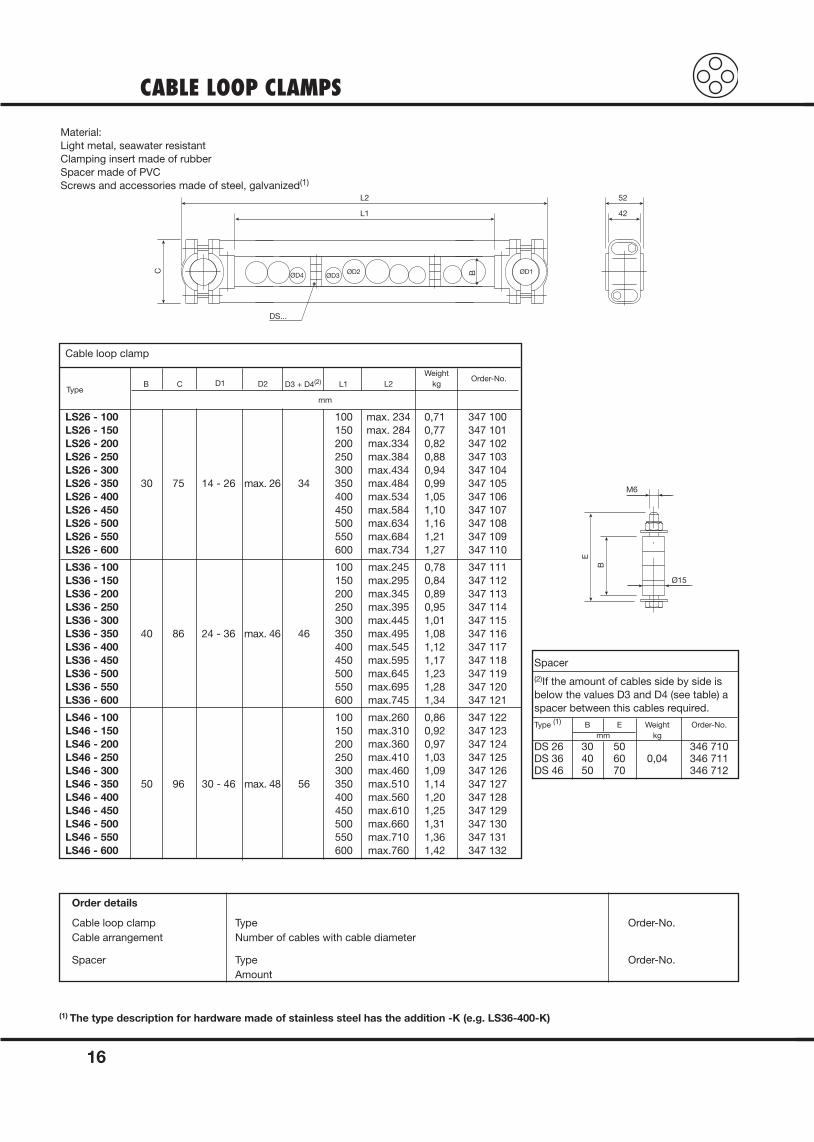
CABLE LOOP CLAMPS
16
Material: Light metal, seawater resistant Clamping insert made of rubberSpacer made of PVCScrews and accessories made of steel, galvanized(1)
TypeB
Order-No.
Cable loop clamp
C D1 D2 D3 + D4(2) L1 L2Weight
kg
mm
LS26 - 100 100 max. 234 0,71 347 100LS26 - 150 150 max. 284 0,77 347 101LS26 - 200 200 max.334 0,82 347 102LS26 - 250 250 max.384 0,88 347 103LS26 - 300 300 max.434 0,94 347 104LS26 - 350 30 75 14 - 26 max. 26 34 350 max.484 0,99 347 105LS26 - 400 400 max.534 1,05 347 106LS26 - 450 450 max.584 1,10 347 107LS26 - 500 500 max.634 1,16 347 108LS26 - 550 550 max.684 1,21 347 109LS26 - 600 600 max.734 1,27 347 110
LS36 - 100 100 max.245 0,78 347 111LS36 - 150 150 max.295 0,84 347 112LS36 - 200 200 max.345 0,89 347 113LS36 - 250 250 max.395 0,95 347 114LS36 - 300 300 max.445 1,01 347 115LS36 - 350 40 86 24 - 36 max. 46 46 350 max.495 1,08 347 116LS36 - 400 400 max.545 1,12 347 117LS36 - 450 450 max.595 1,17 347 118LS36 - 500 500 max.645 1,23 347 119LS36 - 550 550 max.695 1,28 347 120LS36 - 600 600 max.745 1,34 347 121
LS46 - 100 100 max.260 0,86 347 122LS46 - 150 150 max.310 0,92 347 123LS46 - 200 200 max.360 0,97 347 124LS46 - 250 250 max.410 1,03 347 125LS46 - 300 300 max.460 1,09 347 126LS46 - 350 50 96 30 - 46 max. 48 56 350 max.510 1,14 347 127LS46 - 400 400 max.560 1,20 347 128LS46 - 450 450 max.610 1,25 347 129LS46 - 500 500 max.660 1,31 347 130LS46 - 550 550 max.710 1,36 347 131LS46 - 600 600 max.760 1,42 347 132
Spacer(2)If the amount of cables side by side isbelow the values D3 and D4 (see table) aspacer between this cables required.
Type (1) B E Weight Order-No.mm kg
DS 26 30 50 346 710DS 36 40 60 0,04 346 711DS 46 50 70 346 712
Order details
Cable loop clamp Type Order-No.Cable arrangement Number of cables with cable diameter
Spacer Type Order-No.Amount
(1) The type description for hardware made of stainless steel has the addition -K (e.g. LS36-400-K)
DS...
ØD2ØD3ØD4
ØD1B
L1
L2
C
42
52
Ø15E
B
M6
TOW ROPE ASSEMBLIES
17
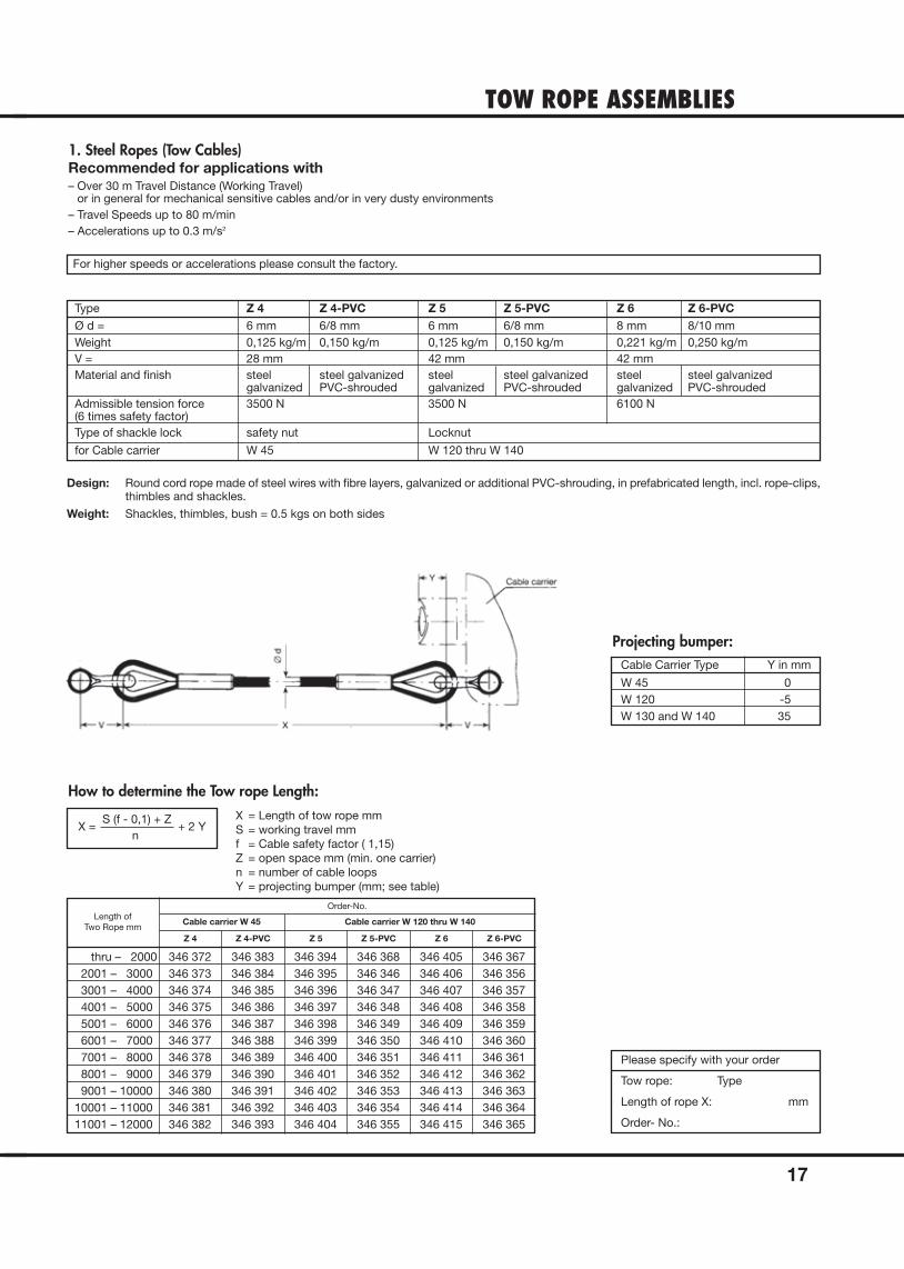
1. Steel Ropes (Tow Cables)Recommended for applications with– Over 30 m Travel Distance (Working Travel)
or in general for mechanical sensitive cables and/or in very dusty environments– Travel Speeds up to 80 m/min– Accelerations up to 0.3 m/s2
For higher speeds or accelerations please consult the factory.
X = S (f - 0,1) + Z
+ 2 Yn
How to determine the Tow rope Length:
Projecting bumper:
X = Length of tow rope mmS = working travel mmf = Cable safety factor ( 1,15)Z = open space mm (min. one carrier)n = number of cable loopsY = projecting bumper (mm; see table)
Type Z 4 Z 4-PVC Z 5 Z 5-PVC Z 6 Z 6-PVCØ d = 6 mm 6/8 mm 6 mm 6/8 mm 8 mm 8/10 mmWeight 0,125 kg/m 0,150 kg/m 0,125 kg/m 0,150 kg/m 0,221 kg/m 0,250 kg/mV = 28 mm 42 mm 42 mmMaterial and finish steel steel galvanized steel steel galvanized steel steel galvanized
galvanized PVC-shrouded galvanized PVC-shrouded galvanized PVC-shroudedAdmissible tension force 3500 N 3500 N 6100 N(6 times safety factor)Type of shackle lock safety nut Locknut
for Cable carrier W 45 W 120 thru W 140
Cable Carrier Type Y in mm
W 45 0W 120 -5W 130 and W 140 35
Length ofTwo Rope mm
Order-No.
Cable carrier W 45
Z 4 Z 4-PVC Z 5 Z 5-PVC Z 6 Z 6-PVC
Cable carrier W 120 thru W 140
Please specify with your order
Tow rope: Type
Length of rope X: mm
Order- No.:
thru – 2000 346 372 346 383 346 394 346 368 346 405 346 3672001 – 3000 346 373 346 384 346 395 346 346 346 406 346 3563001 – 4000 346 374 346 385 346 396 346 347 346 407 346 3574001 – 5000 346 375 346 386 346 397 346 348 346 408 346 3585001 – 6000 346 376 346 387 346 398 346 349 346 409 346 3596001 – 7000 346 377 346 388 346 399 346 350 346 410 346 3607001 – 8000 346 378 346 389 346 400 346 351 346 411 346 3618001 – 9000 346 379 346 390 346 401 346 352 346 412 346 3629001 – 10000 346 380 346 391 346 402 346 353 346 413 346 363
10001 – 11000 346 381 346 392 346 403 346 354 346 414 346 36411001 – 12000 346 382 346 393 346 404 346 355 346 415 346 365
Design: Round cord rope made of steel wires with fibre layers, galvanized or additional PVC-shrouding, in prefabricated length, incl. rope-clips,thimbles and shackles.
Weight: Shackles, thimbles, bush = 0.5 kgs on both sides
SPARE PARTS
18
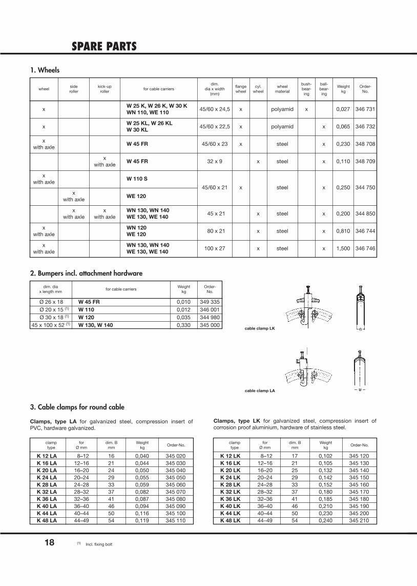
1. Wheels
2. Bumpers incl. attachment hardware
3. Cable clamps for round cable
Clamps, type LA for galvanized steel, compression insert of PVC, hardware galvanized.
Clamps, type LK for galvanized steel, compression insert of corrosion proof aluminium, hardware of stainless steel.
wheel
x
x
xwith axle
xwith axle
xwith axle
xwith axle
xwith axle
xwith axle
xwith axle
xwith axle
sideroller
kick-uproller
for cable carriersdim.
dia x width(mm)
flangewheel
cyl.wheel
wheelmaterial
bush-bear-ing
ball-bear-ing
Weightkg
Order-No.
W 25 K, W 26 K, W 30 KWN 110, WE 110
45/60 x 24,5 x x 0,027
0,065
0,230
0,250
0,200
0,810
1,500
346 731
346 732
348 708
344 750
344 850
346 744
346 746
x
x
0,110 348 709x
x
x
x
x
polyamid
polyamid
steel
steel
steel
steel
steel
steel
x
x
x
x
x
x
x
45/60 x 22,5
45/60 x 23
32 x 9
45/60 x 21
45 x 21
80 x 21
100 x 27
W 25 KL, W 26 KLW 30 KL
W 110 S
W 45 FR
W 45 FR
WE 120
WN 130, WN 140WE 130, WE 140
WN 120WE 120
WN 130, WN 140WE 130, WE 140
dim. diax length mm
for cable carriersWeight
kgOrder-
No.
Ø 26 x 18 W 45 FR 0,010 349 335Ø 20 x 15 (1) W 110 0,012 346 001Ø 30 x 18 (1) W 120 0,035 344 980
45 x 100 x 52 (1) W 130, W 140 0,330 345 000
cable clamp LA
cable clamp LK
clamptype
forØ mm
dim. Bmm
Weightkg
Order-No.clamptype
forØ mm
dim. Bmm
Weightkg
Order-No.
K 12 LA 8–12 16 0,040 345 020K 16 LA 12–16 21 0,044 345 030K 20 LA 16–20 24 0,050 345 040K 24 LA 20–24 29 0,055 345 050K 28 LA 24–28 33 0,059 345 060K 32 LA 28–32 37 0,082 345 070K 36 LA 32–36 41 0,087 345 080K 40 LA 36–40 46 0,094 345 090K 44 LA 40–44 50 0,116 345 100K 48 LA 44–49 54 0,119 345 110
K 12 LK 8–12 17 0,102 345 120K 16 LK 12–16 21 0,105 345 130K 20 LK 16–20 25 0,132 345 140K 24 LK 20–24 29 0,142 345 150K 28 LK 24–28 33 0,152 345 160K 32 LK 28–32 37 0,180 345 170K 36 LK 32–36 41 0,185 345 180K 40 LK 36–40 46 0,210 345 190K 44 LK 40–44 50 0,230 345 200K 48 LK 44–49 54 0,240 345 210
(1) Incl. fixing bolt
19
TYPICAL APPLICATION AND HOW TO ORDER
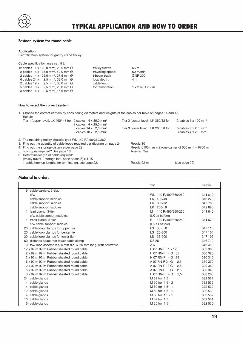
Application:Electrification system for gantry crane trolley
Cable specification: (see cat. 8 L)12 cables 1 x 120,0 mm2, 28,5 mm Ø trolley travel: 65 m
2 cables 4 x 35,0 mm2, 42,0 mm Ø travelling speed: 60 m/min.2 cables 4 x 25,0 mm2, 37,5 mm Ø -beam track NP 2006 cables 24 x 2,5 mm2, 38,0 mm Ø loop depth: 4 m2 cables 19 x 2,5 mm2, 33,0 mm Ø cable length5 cables 8 x 2,5 mm2, 23,0 mm Ø for termination: 1 x 2 m, 1 x 7 m3 cables 4 x 2,5 mm2, 15,5 mm Ø
How to select the correct system:
1. Choose the correct carriers by considering diameters and weights of the cables per table on pages 14 and 15.Result:Tier 1 (upper level): LK 490/ 48 for 2 cables 4 x 35,0 mm2 Tier 2 (center level): LK 360/12 for 12 cables 1 x 120 mm2
2 cables 4 x 25,0 mm2
6 cables 24 x 2,5 mm2 Tier 3 (lower level): LK 260/ 8 for 5 cables 8 x 2,5 mm2
2 cables 18 x 2,5 mm2 3 cables 4 x 2,5 mm2
2. The matching trolley chassis: type WN 140 R/490/360/2603. Find out the quantity of cable loops required per diagram on page 24 Result: 104. Find out the storage distance per page 22 Result: 6100 mm + Z (one carrier of 600 mm) = 6700 mm5. Tow ropes required? See page 18 Answer: Yes6. Determine length of cable required:
(trolley travel + storage incl. open space Z) x 1.15+ cable hookup lengths for termination, see page 22. Result: 92 m (see page 22)
Material to order:
Festoon system for round cable
Type Order-No.
9 cable carriers, 3-tier,c/w WN 140 R/490/360/260 341 610cable support saddles LK 490/48 343 270cable support saddles LK 360/12 342 780cable support saddles LK 260/ 8 342 680
1 lead clamp, 3-tier M 140 R/490/360/260 341 640c/w cable support saddles (LK as before)
1 track clamp, 3-tier E 140 R/490/360/260 341 670c/w cable support saddles (LK as before)
20 cable loop clamps for upper tier LS 36-350 347 11620 cable loop clamps for center tier LS 26-300 347 10420 cable loop clamps for lower tier LS 26-200 347 10260 distance spacer for lower cable clamp DS 26 346 71010 tow rope assemblies, 8 mm dia, 6970 mm long, with hardware Z 6 346 41012 x 92 m 92 m Rubber sheated round cable H 07 RN-F 1 x 120 332 3002 x 92 m 92 m Rubber sheated round cable H 07 RN-F 4 G 35 330 3202 x 92 m 92 m Rubber sheated round cable H 07 RN-F 4 G 25 330 3106 x 92 m 92 m Rubber sheated round cable A 07 RN-F 24 G 2,5 330 3702 x 92 m 92 m Rubber sheated round cable A 07 RN-F 18 G 2,5 330 3605 x 92 m 92 m Rubber sheated round cable A 07 RN-F 8 G 2,5 330 3403 x 92 m 92 m Rubber sheated round cable H 07 RN-F 4 G 2,5 330 260
24 cable glands M 32 for 1,5 332 5314 cable glands M 50 for 1,5 - 2 332 5364 cable glands M 50 for 1,5 - 1 332 532
12 cable glands M 50 for 1,5 - 1 332 5324 cable glands M 50 for 1,5 - 1 332 532
10 cable glands M 32 for 1,5 332 5316 cable glands M 25 for 1,5 332 530
INSTALLATION INFORMATIONwith the associated cable carriers
20
1. Install -beam track parallel with runway of equipment; the side clearance to be sufficient to avoid interference with swinging cables.
2. The support structure for the -beam must be adequately designed for the anticipated loads. Smooth out welded joints to ensure smooth traversing of cable carriers.
The support of the -profile has to take place according to the occurring load. The joints have to carried out aligned.At the tread the welding seams have to be smoothed.
-Beam Track
The system must be installed in the following order:
1. Cable carriers: adjusted per choosen -beam
2. Bolt track clamp: to the lower flange of the -beam
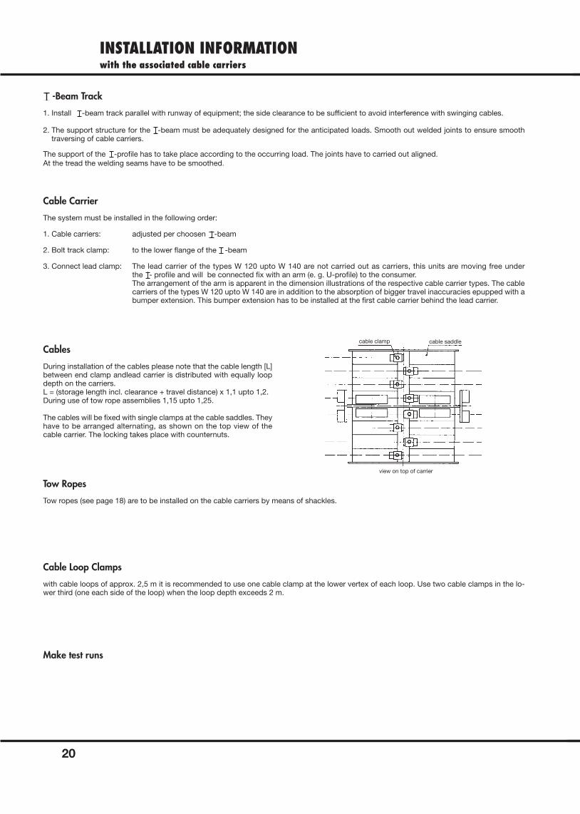
3. Connect lead clamp: The lead carrier of the types W 120 upto W 140 are not carried out as carriers, this units are moving free under the - profile and will be connected fix with an arm (e. g. U-profile) to the consumer. The arrangement of the arm is apparent in the dimension illustrations of the respective cable carrier types. The cablecarriers of the types W 120 upto W 140 are in addition to the absorption of bigger travel inaccuracies epupped with abumper extension. This bumper extension has to be installed at the first cable carrier behind the lead carrier.
Cable Carrier
During installation of the cables please note that the cable length [L]between end clamp andlead carrier is distributed with equally loopdepth on the carriers.L = (storage length incl. clearance + travel distance) x 1,1 upto 1,2. During use of tow rope assemblies 1,15 upto 1,25.
The cables will be fixed with single clamps at the cable saddles. Theyhave to be arranged alternating, as shown on the top view of the cable carrier. The locking takes place with counternuts.
Cables
Tow ropes (see page 18) are to be installed on the cable carriers by means of shackles.
Tow Ropes
with cable loops of approx. 2,5 m it is recommended to use one cable clamp at the lower vertex of each loop. Use two cable clamps in the lo-wer third (one each side of the loop) when the loop depth exceeds 2 m.
Cable Loop Clamps
Make test runs
cable clamp cable saddle
view on top of carrier
HOW TO DETERMINE:Storage Distance, Cable Length, Number of Carriers
21
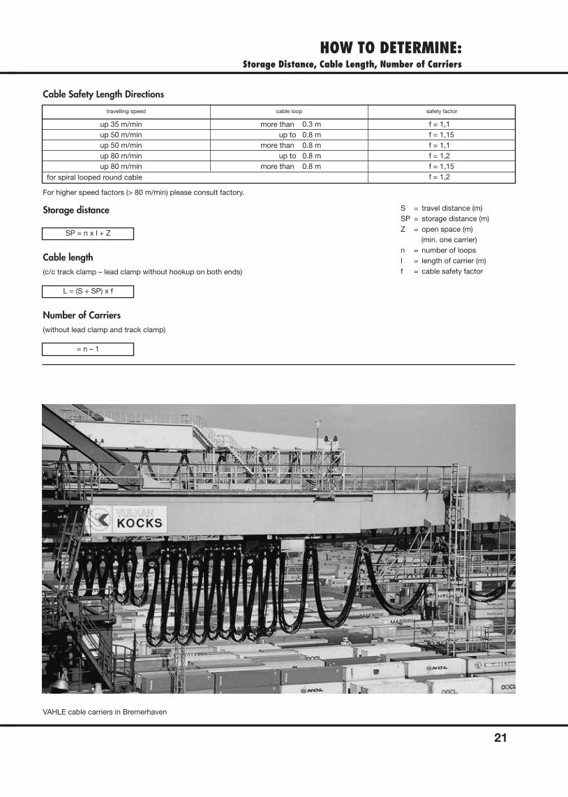
Cable Safety Length Directions
Storage distance
SP = n x l + Z
Cable length(c/c track clamp – lead clamp without hookup on both ends)
L = (S + SP) x f
Number of Carriers(without lead clamp and track clamp)
= n – 1
For higher speed factors (> 80 m/min) please consult factory.
S = travel distance (m)SP = storage distance (m)Z = open space (m)
(min. one carrier)n = number of loopsl = length of carrier (m)f = cable safety factor
VAHLE cable carriers in Bremerhaven
travelling speed cable loop safety factor
up 35 m/min more than 0.3 m f = 1,1up 50 m/min up to 0.8 m f = 1,15up 50 m/min more than 0.8 m f = 1,1up 80 m/min up to 0.8 m f = 1,2up 80 m/min more than 0.8 m f = 1,15
f = 1,2for spiral looped round cable
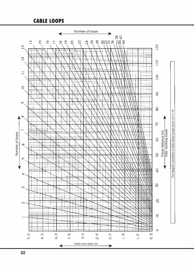
CABLE LOOPS
22
Num
ber
of
loo
ps
Number of loops
Tra
vel d
ista
nce (m
)
max. w
ork
ing
tra
vel
The d
iag
ram
co
nsid
ers
a c
ab
le s
afe
ty leng
ht
facto
r o
f f=
1.1
0
Cable loop depth (m)
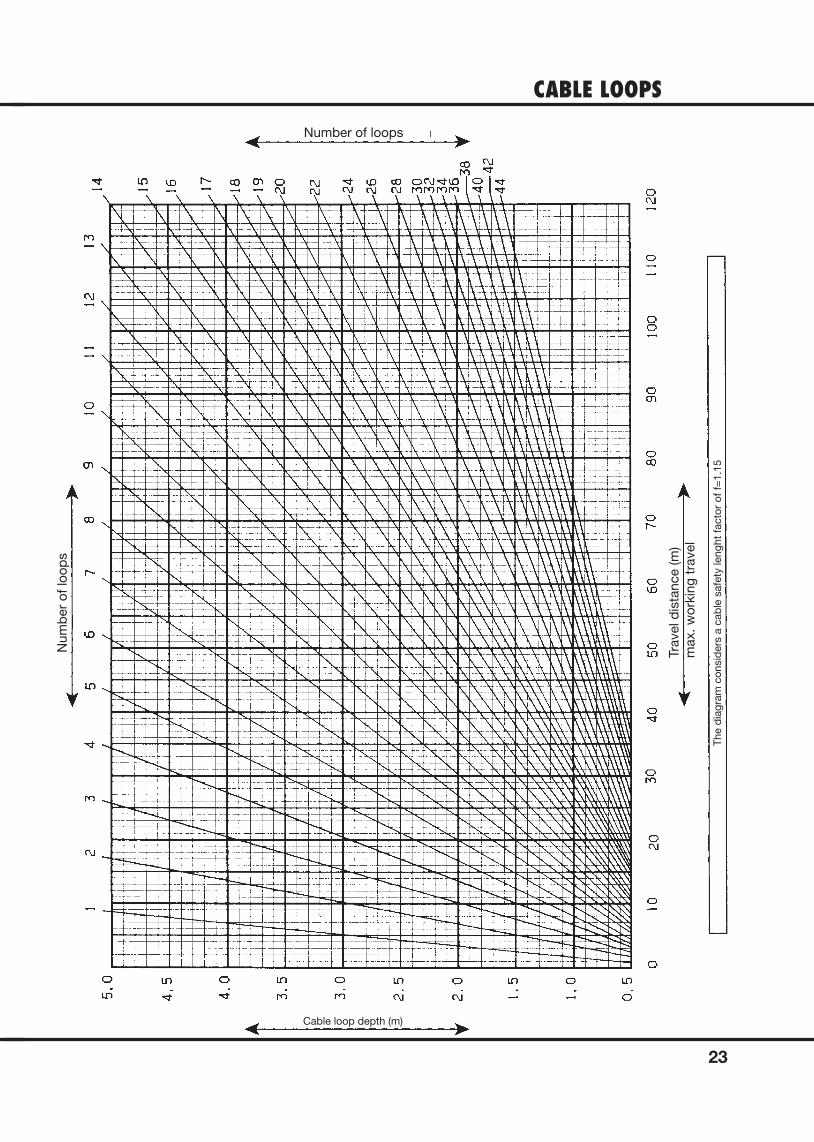
CABLE LOOPS
23
Num
ber
of
loo
ps
Number of loops
Tra
vel d
ista
nce (m
)
max. w
ork
ing
tra
vel
The d
iag
ram
co
nsid
ers
a c
ab
le s
afe
ty leng
ht
facto
r o
f f=
1.1
5
Cable loop depth (m)
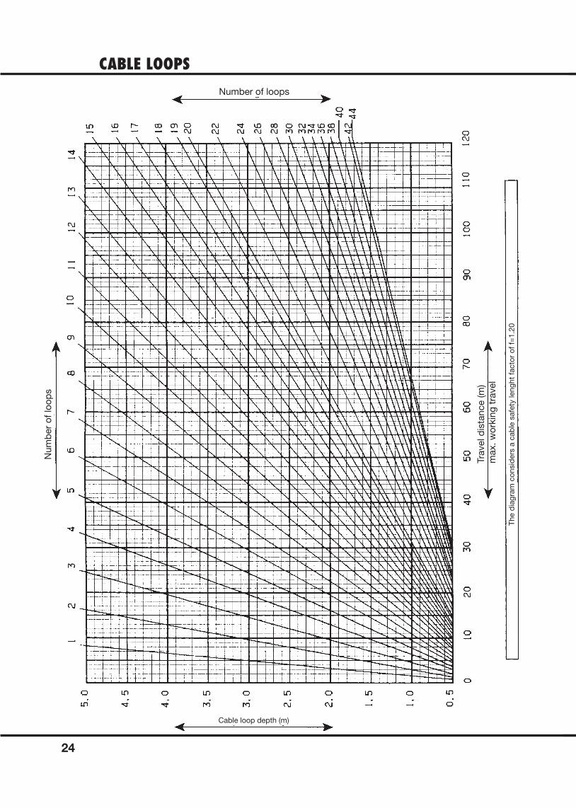
CABLE LOOPS
24
Num
ber
of
loo
ps
Number of loops
Tra
vel d
ista
nce (m
)
max. w
ork
ing
tra
vel
The d
iag
ram
co
nsid
ers
a c
ab
le s
afe
ty leng
ht
facto
r o
f f=
1.2
0
Cable loop depth (m)
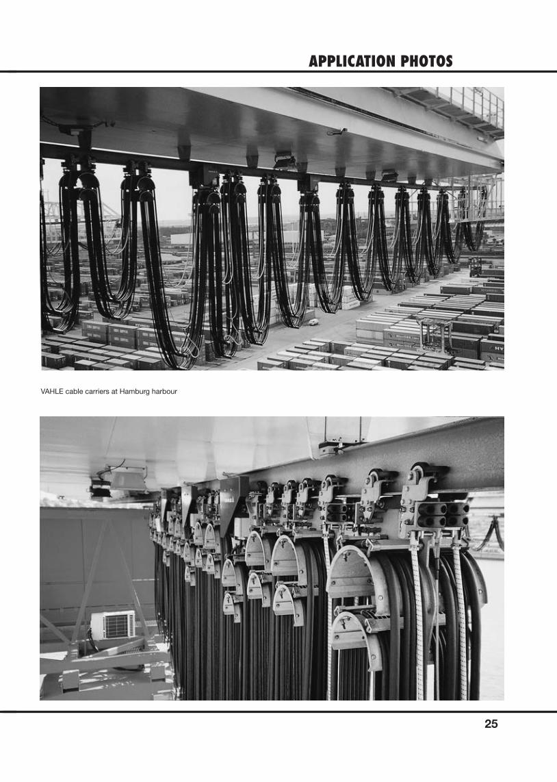
APPLICATION PHOTOS
25
VAHLE cable carriers at Hamburg harbour

NOTES
26
NOTES
27We reserve all rights to make alterations in the interests of further development.
Paul Vahle GmbH & Co. KGWesticker Str. 52
59174 KamenGermany
Tel.: +49 2307 704-0Fax: +49 2307 704-444
www.vahle.com
W11
0012
6/00
-E |
500
| 0
8/19
| E
rrors
and
tech
nica
l mod
ifi ca
tion
subj
ect t
o ch
ange
.
Katalog_8c_Leitungswagen_für_Rundleitungen-Umschlag.indd 2 14.08.2019 12:07:32