cable fault location in a dc microgrid using current ... · cable fault location in a dc ... in...
TRANSCRIPT
Cable Fault Location in a DC MicrogridUsing Current Injection Technique
Rabindra Mohanty, Student Member, IEEEElectrical Engineering Department
Indian Institute of TechnologyKharagpur, India-721302
A. K. Pradhan, Senior Member, IEEEElectrical Engineering Department
Indian Institute of TechnologyKharagpur, India-721302
Abstract—The idea of accurate fault location in dis-tribution system expedites maintenance process, quickrestoration and shorten the power outage duration. InDC microgrid, an existing fault location technique thatassumes the natural frequency of the system is equal todamped resonant frequency of probe current suppliedby probe power unit (PPU) evidences significant errorin calculation of fault location. To estimate all possiblelocation of line fault in low voltage DC microgrids, aportable current injection kit (CIK) is proposed in thispaper. Calculating attenuation and damping frequencyof the injected current the fault distance is obtained.The validity of the proposed method is tested consideringhigh fault resistance, different fault types and radial andlooped network topologies. Using MATLAB, the perfor-mance studies of the proposed fault location algorithmhave been carried out through detailed simulations andmore accuracy is evidenced.
Index Terms—Low voltage DC microgrid, Fault dis-tance, DC transient, damping frequency, attenuationconstant.
NOMENCLATURE
R resistance of injection kit circuit with faulted pathL inductance of injection kit circuit with faulted pathR1 line resistance to fault locationL1 line inductance to fault locationRf fault resistanceLp is the injection kit inductanceCp is the injection kit capacitanceRu resistance of the line per unit lengthLu inductance of the line per unit lengthd distance to the fault locationl overall line distance length
ip(t) injection kit currentα attenuationζ damping co-efficientωn natural frequencyωd damping frequency
I. INTRODUCTION
LOCATING fault by traditional method in a distri-bution system with several branches is difficult.
The strength of accurate fault location leads to advan-tages such as expeditious maintenance, rapid restora-tion and, hence, power outage duration minimization
[1]. One of the features of advanced DC system isto use power electronic converters to optimize powerflow, power quality, and the size and weight of thedistribution equipment. During fault, the current islimited due to presence of power electronic devices upto some extend that leads to difficulty in estimatingfault location operation [2], [3]. The most commonfault location methods are based on impedance mea-surement and traveling wave [4]. Traditional distanceprotection is impedance based measurement at powerfrequency (50 Hz), this only has an accuracy of a fewkilometers and so this is not suitable for distributionsystems [5]. In [6]–[9], fault location technique isproposed based on reflected wave detection and dis-crimination which is an issue in case of close-in faults.For multi-terminal DC (MTDC) system, a travelingwave based fault location method is described in [10].In such system, the limitation is due to variations ofthe shortest paths to the different detectors from thefault location point. Traveling wave and time-domainbased fault location algorithms are used in high volt-age DC (HVDC) transmission line. Fault generatedtraveling wave takes time for its propagation in thetransmission line depending upon the fault position.Moreover, the accuracy of such methods depends onthe accurate detection of the surge arrival time andrequires high performance data acquisition equipment[11], [12].
DC distributed system is a new concept in electricpower system. The growth of distributed energy re-sources (DERs) and the DC loads increase the numberof branches of DC distributed networks and make itdifficult to accurately locate a DC line fault [1], [13],[14]. The traditional fault location methods in highvoltage DC network often use the natural frequencybased fault location [15]. Active impedance estimation(AIE) approach is applied in marine DC power system[16]. Recently, noniterative fault-location techniqueusing PPU, is proposed for low voltage DC microgrid[17]. However, damping coefficient (ζ) of currentresponse id not considered in here. Furthermore, theassumption of natural frequency of the system is equalto damped frequency of current response incorporatesthe error in fault distance calculation.
In this paper, a new method is proposed to ac-978-1-4799-5141-3/14/$31.00 c© 2016 IEEE
Normal AC
loads
Sensi
tive
DC
load
s
Sensitiv
e AC
load
s
Battery
Utility Grid
PV Array
AC bus
Wind Generator
Sensitive DC
loads
PC
C
DC Microgrid
Solid State
Circuit Breaker
Kit Connection Point
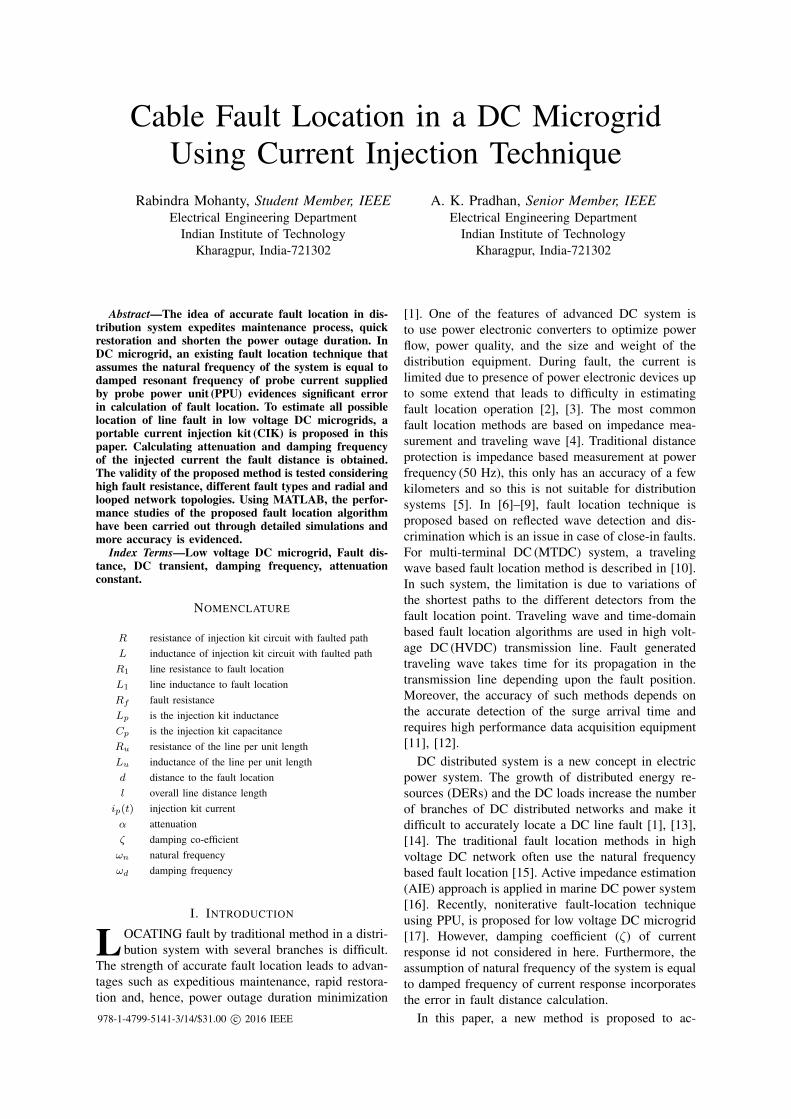
Fig. 1. DC microgrid with CIK connection point
curately locate a fault in DC line using attenuationconstant (α) in damped injected current response. Thedamping coefficient is a function of fault resistance andtherefore, it leads to inaccuracy if neglected. Usingfast fourier transform (FFT) algorithm, the dampedresonant frequency is obtained from sampled currentdata. The attenuation constant is calculated from thepeak values of underdamped injected current response.This method does not require online voltage or currentdata to calculate the fault, hence this improves theaccuracy and more economical. The accuracy andeffectiveness of the method have been tested and foundto be more accurate.
This paper is divided into five sections. Section I isdevoted to introduction. In section II, low voltage DCmicrogrid is briefly discussed. The proposed fault lo-cation technique is explained in section III, simulationresults including comparison study with the method[17] are given in section IV. The overall conclusionsare given in section V.
II. LOW VOLTAGE DC MICROGRID
Renewable energy sources like photo-voltaic array.fuel cell and storage devides are inherently producingDC power. In compatible to that, most of the sensi-tive electronic loads like computers, mobiles and fan,LEDs, electric vehicles consume DC. DC bus micro-grid provides a platform for balance of such generationand demand with higher economy, efficiency and reli-ability. The reduction of AC-DC-AC conversion stagesenhances the efficiency and minimizes the cost in DCdistribution system [13].
Moreover, for same cable DC can deliver√
2 timesmore power than AC. This is because, the peak voltageof the DC system is same as rms and that of AC system
id√
2 times more. DC systems do not experience theskin effect and corona loss. Hence, DC system utilizesthe entire cable that leads decrease in losses [18], [19].DC microgrid can be operated either in grid connectedmode or islanded mode. In case demand of microgridexceeds its generation, the extra power flows from gridand reverse power flow occurs for higher generationcompared to demand in microgrid. A low voltage DCmicrogrid system is shown in Fig. 1. The microgridis operated in grid connected mode and consists ofsources like PV array and wind generator. Both ACand DC type loads are considered in the system. Loadsare connected through DC-DC or AC-DC convertersto the DC bus.
III. PROPOSED FAULT LOCATION METHOD
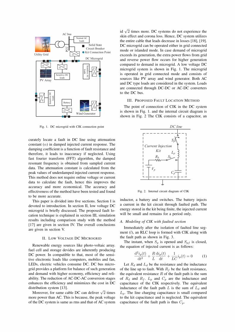
The point of connection of CIK in the DC systemis shown in Fig. 1. and the internal circuit diagram isshown in Fig. 2 The CIK consists of a capacitor, an
Current Injection
Kit
Sp
Lp
Rb
Cp
Sb
Vp
DC line
Fig. 2. Internal circuit diagram of CIK
inductor, a battery and switches. The battery injectsa current in the kit circuit through faulted path. Theenergy stored in the kit being finite, the injected currentwill be small and remains for a period only.
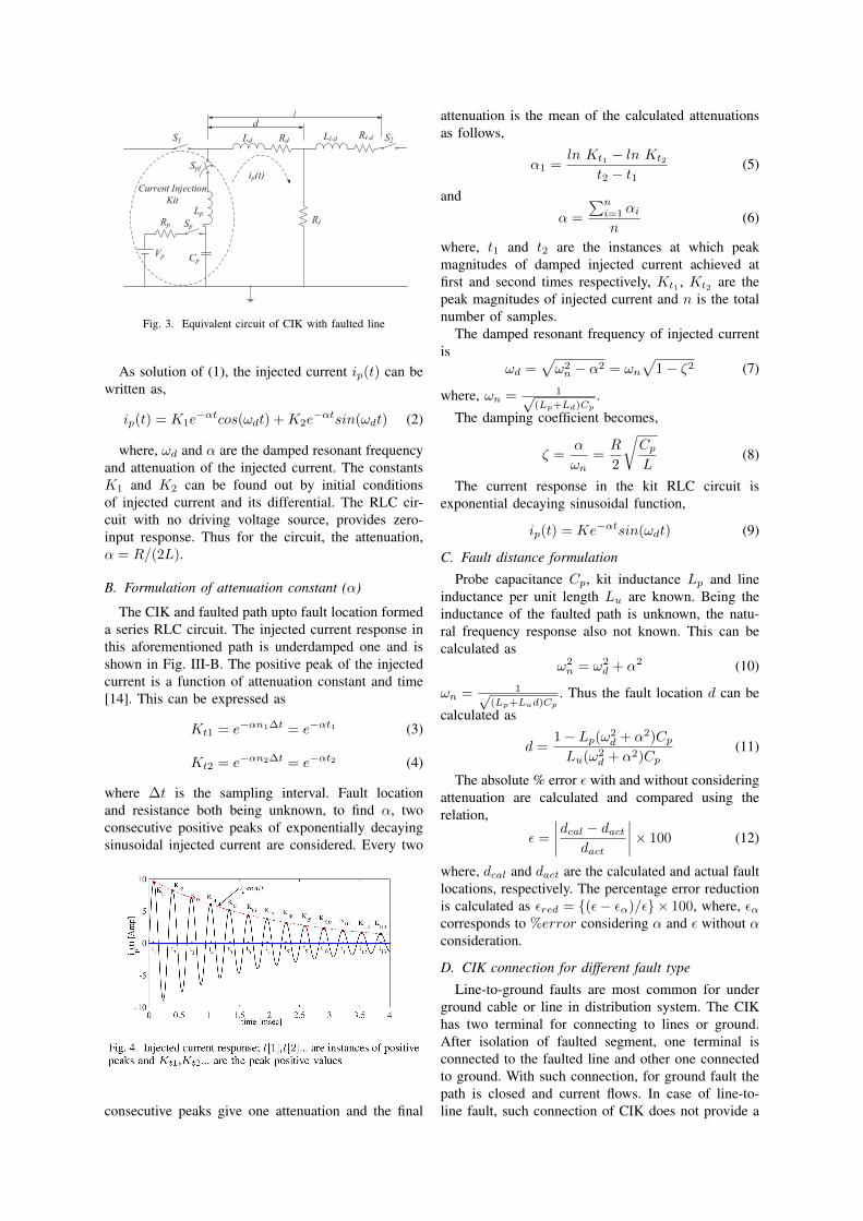
A. Modeling of CIK with faulted section
Immediately after the isolation of faulted line seg-ment (l), an RLC loop is formed with CIK along withthe fault path as shown in Fig. 3.
The instant, when Sp is opened and Spf is closed,the equation of injected current is as follows:
d2ip(t)
dt2+R
L
dip(t)
dt+
1
LCip(t) = 0 (1)
Let Rd and Ld be the resistance and the inductanceof the line up to fault. With Rf be the fault resistance,the equivalent resistance R of the fault path is the sumof Rd and Rf . Lp and Cp are the inductance andcapacitance of the CIK respectively. The equivalentinductance of the fault path L is the sum of Ld andLp. The line charging capacitance is small comparedto the kit capacitance and is neglected. The equivalentcapacitance of the fault path is thus Cp.
Current Injection
Kit
Spf
S1 S2Ld Ll-dRdRl-d
Lp
Rp
Cp
SpRf
dl
ip(t)
Vp
Fig. 3. Equivalent circuit of CIK with faulted line
As solution of (1), the injected current ip(t) can bewritten as,
ip(t) = K1e−αtcos(ωdt) +K2e
−αtsin(ωdt) (2)
where, ωd and α are the damped resonant frequencyand attenuation of the injected current. The constantsK1 and K2 can be found out by initial conditionsof injected current and its differential. The RLC cir-cuit with no driving voltage source, provides zero-input response. Thus for the circuit, the attenuation,α = R/(2L).
B. Formulation of attenuation constant (α)
The CIK and faulted path upto fault location formeda series RLC circuit. The injected current response inthis aforementioned path is underdamped one and isshown in Fig. III-B. The positive peak of the injectedcurrent is a function of attenuation constant and time[14]. This can be expressed as
Kt1 = e−αn1∆t = e−αt1 (3)
Kt2 = e−αn2∆t = e−αt2 (4)
where ∆t is the sampling interval. Fault locationand resistance both being unknown, to find α, twoconsecutive positive peaks of exponentially decayingsinusoidal injected current are considered. Every two
consecutive peaks give one attenuation and the final
attenuation is the mean of the calculated attenuationsas follows,
α1 =ln Kt1 − ln Kt2
t2 − t1(5)
andα =
∑ni=1 αin
(6)
where, t1 and t2 are the instances at which peakmagnitudes of damped injected current achieved atfirst and second times respectively, Kt1 , Kt2 are thepeak magnitudes of injected current and n is the totalnumber of samples.
The damped resonant frequency of injected currentis
ωd =√ω2n − α2 = ωn
√1− ζ2 (7)
where, ωn = 1√(Lp+Ld)Cp
.
The damping coefficient becomes,
ζ =α
ωn=R
2
√CpL
(8)
The current response in the kit RLC circuit isexponential decaying sinusoidal function,
ip(t) = Ke−αtsin(ωdt) (9)
C. Fault distance formulation
Probe capacitance Cp, kit inductance Lp and lineinductance per unit length Lu are known. Being theinductance of the faulted path is unknown, the natu-ral frequency response also not known. This can becalculated as
ω2n = ω2
d + α2 (10)
ωn = 1√(Lp+Lud)Cp
. Thus the fault location d can be
calculated as
d =1− Lp(ω2
d + α2)CpLu(ω2
d + α2)Cp(11)
The absolute % error ε with and without consideringattenuation are calculated and compared using therelation,
ε =
∣∣∣∣dcal − dactdact
∣∣∣∣× 100 (12)
where, dcal and dact are the calculated and actual faultlocations, respectively. The percentage error reductionis calculated as εred = (ε− εα)/ε× 100, where, εαcorresponds to %error considering α and ε without αconsideration.
D. CIK connection for different fault type
Line-to-ground faults are most common for underground cable or line in distribution system. The CIKhas two terminal for connecting to lines or ground.After isolation of faulted segment, one terminal isconnected to the faulted line and other one connectedto ground. With such connection, for ground fault thepath is closed and current flows. In case of line-to-line fault, such connection of CIK does not provide a
close path for current and operator can not find currentresponse. For such fault type, the ground point of CIKmust be connected to other line of the DC system. Thisprovides a close path for current and fault distance canbe obtained using proposed algorithm.
Measure ip(t)
Positive peaks of ip(t)
Extract the ωd from ip(t) using
FFT
Calculate d using (11)
Calculate α1 using two
consecutive peaks
Is α negligible ?
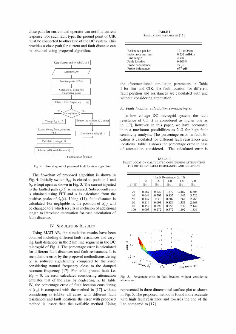
Keep Sp open and switch Spf to 1
Change Spf to 2 Extract the ωd from ip(t) using
FFT
Calculate d using (11)
Subtract additional distance dp
NoYes
Fault location obtained
Obtain α from Avg(α1,α2,…...α5)
Fig. 4. Flow diagram of proposed fault location algorithm
The flowchart of proposed algorithm is shown inFig. 4. Initially switch Spf is closed to position 1 andSp is kept open as shown in Fig. 3. The current injectedto the faulted path ip(t) is measured. Subsequently ωdis obtained using FFT and α is calculated from thepositive peaks of ip(t). Using (11), fault distance iscalculated. For negligible α, the position of Spf willbe changed to 2 which results in inclusion of additionallength to introduce attenuation for ease calculation offault distance.
IV. SIMULATION RESULTS
Using MATLAB, the simulation results have beenobtained including different fault resistances and vary-ing fault distances in the 2 km line segment in the DCmicrogrid of Fig. 1. The percentage error is calculatedfor different fault distances and fault resistances. It isseen that the error by the proposed method(consideringα) is reduced significantly compared to the errorconsidering natural frequency close to the dampedresonant frequency [17]. For solid ground fault i.e.Rf = 0, the error calculated considering attenuationemulates that of the case by neglecting α. In TableIV, the percentage error of fault location consideringα (εα) is compared with the method in [17] withoutconsidering α (ε).For all cases with different faultresistances and fault locations the error with proposedmethod is lesser than the available method. Using
TABLE ISIMULATION PARAMETER [13]
Resistance per km 121 mΩ/kmInductance per km 0.232 mH/kmLine length 2 kmFault location 0-100%Probe capacitance 27 µFProbe inductance 657 µH
the aforementioned simulation parameters in TableI for line and CIK, the fault location for differentfault position and resistances are calculated with andwithout considering attenuation.
A. Fault location calculation considering α
In low voltage DC microgrid system, the faultresistance of 0.5 Ω is considered as higher one asin [17], however, in this paper, we have accountedit to a maximum possibilities as 2 Ω for high faultsensitivity analysis. The percentage error in fault lo-cation is calculated for different fault resistances andlocations. Table II shows the percentage error in caseof attenuation considered. The calculated error is
TABLE IIFAULT LOCATION CALCULATED CONSIDERING ATTENUATION
FOR DIFFERENT FAULT RESISTANCES AND LOCATIONS
Fault Resistance (in Ω)0 0.5 1.0 1.5 2.0
d (%) %εα %εα %εα %εα %εα
20 0.287 0.329 1.779 3.487 6.60840 0.049 0.203 0.835 1.942 3.52650 0.147 0.33 0.607 1.864 2.76360 0.114 0.093 0.884 1.383 2.46380 0.152 0.092 0.555 1.239 2.142
100 0.003 0.272 0.372 1.192 1.836
Fig. 5. Percentage error in fault location without consideringattenuation
represented in three dimensional surface plot as shownin Fig. 5. The proposed method is found more accuratewith high fault resistance and towards the end of theline compared to [17].
B. Fault location calculation without α
The percentage error in fault location, not con-sidering attenuation is listed in Table III and foundprominent error because of not accounting resistanceof the series RLC faulted path from kit to faultposition. Fig. 6 shows the percentage error with respectto different fault resistances and locations.
TABLE IIIFAULT LOCATION CALCULATED WITHOUT CONSIDERINGATTENUATION FOR DIFFERENT FAULT RESISTANCES AND
LOCATIONS
Fault Resistance (in Ω)0 0.5 1.0 1.5 2.0
d (%) %ε %ε %ε %ε %ε
20 0.283 0.856 3.735 7.843 7.84340 0.057 0.514 1.897 4.236 7.58650 0.157 0.600 1.492 3.753 6.05960 0.102 0.335 1.655 2.992 5.25880 0.136 0.301 1.182 2.518 4.329100 0.017 0.464 0.913 2.273 3.654
Fig. 6. Percentage error in fault location without consideringattenuation
TABLE IVPERCENTAGE ERROR COMPARISON BETWEEN PROPOSED
METHOD AND THE METHOD IN [17].
Fault Resistance (in Ω)
0.5 1.0 1.5 2.0
l(%) ε εα ε εα ε εα ε εα
20 0.856 0.329 3.735 1.779 7.843 3.487 7.852 6.60840 0.514 0.203 1.897 0.835 4.236 1.942 7.586 3.52650 0.600 0.330 1.492 0.607 3.753 1.864 6.059 2.76360 0.335 0.093 1.655 0.884 2.992 1.383 5.258 2.46380 0.301 0.092 1.182 0.555 2.518 1.239 4.329 2.142100 0.464 0.272 0.913 0.372 2.273 1.192 3.654 1.836
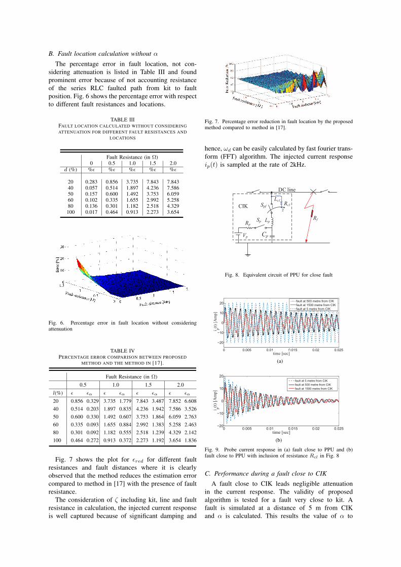
Fig. 7 shows the plot for εred for different faultresistances and fault distances where it is clearlyobserved that the method reduces the estimation errorcompared to method in [17] with the presence of faultresistance.
The consideration of ζ including kit, line and faultresistance in calculation, the injected current responseis well captured because of significant damping and
Fig. 7. Percentage error reduction in fault location by the proposedmethod compared to method in [17].
hence, ωd can be easily calculated by fast fourier trans-form (FFT) algorithm. The injected current responseip(t) is sampled at the rate of 2kHz.
Sp LpRp
Cp
Spf
Vp
DC line
Rf
Rcl2
1
Lcl
Fig. 8. Equivalent circuit of PPU for close fault
0 0.005 0.01 0.015 0.02 0.025
−20
−10
0
10
20
time [sec]
i p(t
) [A
mp
]
fault at 500 metre from
fault at 1500 metre from
fault at 5 metre from
(a)
0 0.005 0.01 0.015 0.02 0.025−20
−10
0
10
20
time [sec]
i p(t
) [A
mp
]
fault at 5 metre from
fault at 500 metre from
fault at 1500 metre from
(b)
Fig. 9. Probe current response in (a) fault close to PPU and (b)fault close to PPU with inclusion of resistance Rcl in Fig. 8
C. Performance during a fault close to CIK
A fault close to CIK leads negligible attenuationin the current response. The validity of proposedalgorithm is tested for a fault very close to kit. Afault is simulated at a distance of 5 m from CIKand α is calculated. This results the value of α to
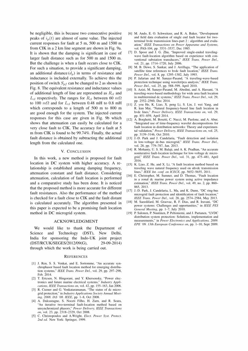
be negligible, this is because two consecutive positivepeaks of ip(t) are almost of same value. The injectedcurrent responses for fault at 5 m, 500 m and 1500 mfrom CIK in a 2 km line segment are shown in Fig. 9a.It is shown that the damping is significant in case oflarger fault distance such as for 500 m and 1500 m.But the challenge is when a fault occurs close to CIK.For such a situation, to provide a significant damping,an additional distance (dp) in terms of resistance andinductance is included externally. To achieve this theposition of switch Spf can be changed to 2 as shown inFig. 8. The equivalent resistance and inductance valuesof additional length of line are represented as Rcl andLcl respectively. The ranges for Rcl between 60 mΩto 100 mΩ and for Lcl between 0.48 mH to 0.8 mHwhich corresponds to a length of 500 m to 800 mare good enough for the system. The injected currentresponses for this case are given in Fig. 9b whichshows that attenuation can easily be calculated for avery close fault to CIK. The accuracy for a fault at 5m from CIK is found to be 99.74%. Finally, the actualfault distance is obtained by subtracting the additionallength from the calculated one.
V. CONCLUSION
In this work, a new method is proposed for faultlocation in DC system with higher accuracy. A re-lationship is established among damping frequency,attenuation constant and fault distance. Consideringattenuation, calculation of fault location is performedand a comparative study has been done. It is noticedthat the proposed method is more accurate for differentfault resistances. Also the performance of the methodis checked for a fault close to CIK and the fault distantis calculated accurately. The algorithm presented inthis paper is expected to be a promising fault locationmethod in DC microgrid system.
ACKNOWLEDGMENT
We would like to thank the Department ofScience and Technology (DST), New Delhi,India for sponsoring the Indo-UK joint project(DST/RCUK/SEGES/2012/09(G), 29-09-2014)through which the work is being carried out.
REFERENCES
[1] J. Ren, S. S. Venkat, and E. Sortomme, “An accurate syn-chrophasor based fault location method for emerging distribu-tion systems,” IEEE Trans. Power Del., vol. 29, pp. 297–298,Feb. 2014.
[2] T. Ericsen, N. Hingorani, and Y. Khersonsky, “Power elec-tronics and future marine electrical systems,” Industry Appli-cations, IEEE Transactions on, vol. 42, pp. 155–163, Jan 2006.
[3] R. Cuzner and G. Venkataramanan, “The status of dc micro-grid protection,” in Industry Applications Society Annual Meet-ing, 2008. IAS ’08. IEEE, pp. 1–8, Oct 2008.
[4] A. Dalcastagne, S. Noceti Filho, H. Zurn, and R. Seara,“An iterative two-terminal fault-location method based onunsynchronized phasors,” Power Delivery, IEEE Transactionson, vol. 23, pp. 2318–2329, Oct 2008.
[5] C. Christopoulos and A.Wright, Elect. Power Syst. Protect.2nd ed. New York: Springer, 1999.
[6] M. Ando, E. O. Schweitzer, and R. A. Baker, “Developmentand field data evaluation of single end fault locator for two-terminal hvdc transmission lines-part 2 : algorithm and evalu-ation,” IEEE Transactions on Power Apparatus and Systems,vol. PAS-104, pp. 3531–3537, Dec 1985.
[7] D. Spoor and J. G. Zhu, “Improved single-ended traveling-wave fault-location algorithm based on experience with con-ventional substation transducers,” IEEE Trans. Power Del.,vol. 21, pp. 1714–1720, July 2006.
[8] M. B. Dewe, S. Sankar, and J. Arrillaga, “The application ofsatellite time references to hvdc fault location,” IEEE Trans.Power Del., vol. 8, pp. 1295–1302, July 1993.
[9] P. Jafarian and M. Sanaye-Pasand, “A traveling-wave-basedprotection technique using wavelet/pca analysis,” IEEE Trans.Power Del., vol. 25, pp. 588–599, April 2010.
[10] S. Azizi, M. Sanaye-Pasand, M. Abedini, and A. Hassani, “Atraveling-wave-based methodology for wide area fault locationin multiterminal dc systems,” IEEE Trans. Power Del., vol. 29,pp. 2552–2560, Dec 2014.
[11] Z. you He, K. Liao, X. peng Li, S. Lin, J. wei Yang, andR. kun Mai, “Natural frequency-based line fault location inhvdc lines,” Power Delivery, IEEE Transactions on, vol. 29,pp. 851–859, April 2014.
[12] A. Borghetti, M. Bosetti, C. Nucci, M. Paolone, and A. Abur,“Integrated use of time-frequency wavelet decompositions forfault location in distribution networks: Theory and experimen-tal validation,” Power Delivery, IEEE Transactions on, vol. 25,pp. 3139–3146, Oct 2010.
[13] J.-D. Park and J. Candelaria, “Fault detection and isolationin low-voltage dc-bus microgrid,” IEEE Trans. Power Del.,vol. 28, pp. 779–787, Jan. 2013.
[14] R. Mohanty, U. S. M. Balaji, and A. K. Pradhan, “An accuratenoniterative fault-location technique for low-voltage dc micro-grid,” IEEE Trans. Power Del., vol. 31, pp. 475–481, April2016.
[15] K. Liao, Z. He, and X. Li, “A fault location method based ontraveling wave natural frequency used on uhvdc transmissionlines,” IEEE Int. conf. on ICECE, pp. 5652–5655, 2011.
[16] E. Christopher, M. Sumner, and D. Thomas, “Fault locationin a zonal dc marine power system using active impedanceestimation,” IEEE Trans. Power Del., vol. 49, no. 2, pp. 860–865, 2013.
[17] J.-D. Park, J. Candelaria, L. Ma, and K. Dunn, “DC ring-busmicrogrid fault protection and identification of fault location,”IEEE Trans. Power Del., vol. 28, pp. 2574–2584, May 2013.
[18] M. Saeedifard, M. Graovac, R. F. Dias, and R. Iravani, “DCpower systems: Challenges and opportunities,” in IEEE PESGeneral Meeting, pp. 1–7, July 2010.
[19] P. Salonen, P. Nuutinen, P. Peltoniemi, and J. Partanen, “LVDCdistribution system protection: Solutions, implementation andmeasurements,” in Power Electronics and Applications, 2009.EPE ’09. 13th European Conference on, pp. 1–10, Sept 2009.