cable-suspended haptic interface - ohio university
TRANSCRIPT

1
CABLE-SUSPENDED HAPTIC INTERFACE
Robert L. Williams IIDepartment of Mechanical Engineering
Ohio UniversityAthens, OH 45701
International Journal of Virtual RealityVol. 3, No. 3, pp. 13-21
1998
Contact information:Robert L. Williams IIAssistant ProfessorDepartment of Mechanical Engineering257 Stocker CenterOhio UniversityAthens, OH 45701-2979phone: (740) 593 - 1096fax: (740) 593 - 0476email: [email protected]: http://www.ent.ohiou.edu/~bobw

2
CABLE-SUSPENDED HAPTIC INTERFACE
Robert L. Williams II
Ohio University
Athens, OH 45701
ABSTRACT
A cable-suspended haptic interface (CSHI) concept is presented. The goal is to create an
input/output device to provide six-degree-of-freedom (dof) wrench (force and moment) feedback to a
human operator in virtual reality or remote applications. Compared to commercially-available haptic
interfaces for virtual reality applications, the present concept is driving for lighter, safer, crisper, more
dexterous, and more economical operation. The CSHI concept is presented, along with the required
mathematical transformations for use of the device.

3
1. INTRODUCTION
Haptic interfaces provide a sense of wrench (force/moment) and/or tactile feedback to the human
from a computer-simulated or remote environment. Most existing wrench-reflection devices are jointed
robots whose actuators are coordinated to provide a force (and some also provide moment) vector to a
human user's hand (for example, the six-degree-of-freedom (dof) Kraft mini-master of Fig. 1 and the six-
dof JPL force-reflecting hand controller of Fig. 2). These devices are too heavy, strong, expensive, and
not dexterous enough to achieve widespread application. Some commercial devices have appeared more
recently. The three-dof PHANToM (Fig. 3, Massie and Salisbury, 1994) is a jointed device with
reasonable weight but provides only three Cartesian forces (no moments) to the operator's finger tip.
The two-dof Impulse Engine 2000 (Fig. 4, Immersion Corp.) is an active flight stick which provides only
two Cartesian forces via the flight stick handle.
The force-reflecting device proposed is an extension of two recently-developed technologies in
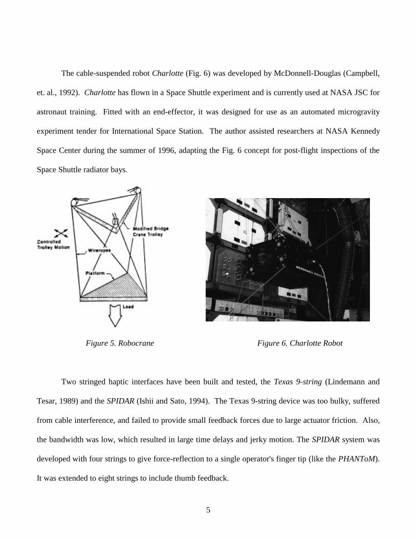
cable-suspended robots and stringed haptic interfaces. A pioneer in cable-suspended robots is NIST
with the Robocrane of Fig. 5 (Albus, et. al., 1993). This device is similar to a six-dof Stewart's platform
(Stewart, 1966), with cables instead of hydraulic-cylinder legs. The Stewart’s platform, consisting of a
six-dof moving table controlled by six hydraulic-cylinder legs, has been widely applied as motion
platforms for flight simulators. In Fig. 5, the lower triangle is a rigid body and the remaining lines are
cables which can independently provide six tensions on the rigid triangle. The upper dashed triangle
indicates a rigid support structure. In this system, gravity is as an implicit actuator which ensures cable
tension is maintained at all times. Robocrane has been proposed for use in shipping ports.

4
Figure 1. Kraft Mini-Master Figure 2. JPL Force-Reflecting Hand Controller
Figure 3. PHANToM Figure 4. Impulse Engine 2000
5
The cable-suspended robot Charlotte (Fig. 6) was developed by McDonnell-Douglas (Campbell,
et. al., 1992). Charlotte has flown in a Space Shuttle experiment and is currently used at NASA JSC for
astronaut training. Fitted with an end-effector, it was designed for use as an automated microgravity
experiment tender for International Space Station. The author assisted researchers at NASA Kennedy
Space Center during the summer of 1996, adapting the Fig. 6 concept for post-flight inspections of the
Space Shuttle radiator bays.
Figure 5. Robocrane Figure 6. Charlotte Robot
Two stringed haptic interfaces have been built and tested, the Texas 9-string (Lindemann and
Tesar, 1989) and the SPIDAR (Ishii and Sato, 1994). The Texas 9-string device was too bulky, suffered
from cable interference, and failed to provide small feedback forces due to large actuator friction. Also,
the bandwidth was low, which resulted in large time delays and jerky motion. The SPIDAR system was
developed with four strings to give force-reflection to a single operator's finger tip (like the PHANToM).
It was extended to eight strings to include thumb feedback.

6
Figure 7. Texas 9-String Figure 8. SPIDAR
The current paper presents a concept for a six-dof cable-suspended haptic interface. Wrench-
reflection is the current focus, although future plans include fusion of wrench/tactile feedback with the
proposed interface. First the concept is presented, followed by required mathematical transformations
for implementation of the device; lastly, the device control is presented and a discussion of VR
applications is given.

7
2. HAPTIC INTERFACE CONCEPT
This section presents the cable-suspended haptic interface (CSHI) concept. The CSHI consists of
a hand-grip supported in-parallel by n-cables controlled by n-independent tensioning actuators, shown in
Fig. 9. Each cable actuator system includes a torque motor, cable reel, tensioning mechanism, plus cable
length and force sensors. For six-dof spatial operation, there must be at least six cables. Since cables
can only exert tension on the hand-grip, there must be more than six cables to avoid configurations
where the hand-grip can go slack. Figure 9 shows eight cables independently controlled by eight
actuators mounted to the frame of the device. This scenario represents actuation redundancy but not
kinematic redundancy. That is, there are two extra motors which provide infinite choices for applying
six-dof wrench vectors, but the hand-grip has only six Cartesian-dof (x, y, z, roll , pitch, yaw).
Figure 9. Cable-Suspended Haptic Interface (CSHI) Concept
Frame
Cables (8)
TensioningActuators
(8)
Hand-Gripwith Tactile
Elements

8
A planar version of this concept has been developed with four cables and planar (x, y, twist)
motions. Figure 10 shows a photograph of the planar CSHI prototype developed by the author and
research assistant Trevor Blackann. This device has served as proof-of-concept in hardware, but the
quality is not yet sufficient to make meaningful comparisons with the existing haptic interfaces reviewed
in the previous section. The motors are too large and easily overpower the human hand. It was learned
that forces in any direction may be readily applied; however, for effective moments (twists) to the human
hand, the cables should connect to opposite corners (as in the Charlotte hardware, Fig. 6). This lesson
and many other from this planar prototype hardware will help determine the specifications and nature of
the spatial prototype hardware, currently under development.
Figure 10. Planar CSHI Prototype
This haptic interface can be used for both input and output. The pose (position and orientation)
of the hand-grip may be calculated and used to command the pose of objects in the virtual/remote world.

9
Velocity commands to virtual objects are also possible, either by interpreting a static hand-grip pose as a
constant velocity or by tracking the velocity of the user's hand. The device is used as output when
reflecting wrenches to the human user. Simulated object weight, mass moment of inertia, stiffness,
dynamics loads, and environment contact forces may thus be felt. The next section gives the forward
kinematics, inverse Jacobian matrix, and statics modeling required for operation of the CSHI.
3. MATHEMATICAL TRANSFORMATIONS
Kinematic modeling is concerned with relating motions of the hand-grip with motions of the
cables. The forward pose kinematics solution is required to calculate operator commands from the
CSHI, while the inverse Jacobian matrix and statics modeling are required to command wrenches to the
hand-grip. These models are non-linear and configuration-dependent.
Figure 9 presents the spatial and Fig. 11 the planar CHSI kinematic diagrams. Figure 9 shows
crossed cables, while Figs. 10 and 11 show non-crossed cables. The methods in this section can be
applied to either crossing case. The crossed-cable case may have moment-applying advantages over the
non-crossed case. The moving frame is {H} and the fixed frame is {0}. The cable index is i,
ni ,,2,1 �= . The dimension of the Cartesian space is m. The number of cables in these examples are
8=n and 4=n for the spatial and planar cases, respectively. Since cables can only exert tension,
generally actuation redundancy ( 68 =>= mn for spatial and 34 =>= mn for planar) is required to
ensure no cables are slack during use. The ground link cable connection points are Gi and the moving
link cable connection points are Hi. Vectors hi give the locations of Hi relative to the origin of {H}. The
cable lengths are Li. The hand-grip point of interest is the origin of {H}. The kinematic equations
derived in this section apply to any general spatial or planar CSHI.

10
g y
h x h y
x H0
Y 0
X H
Y H
h 2
H 4
G 1 G 2
G 3G 4
L 1
L 2
L 3L 4
θ1
θ2
θ3
θ4
H 1
H 2
H 3
φ
g x
X 0
Figure 11. Planar CSHI Kinematic Diagram
3.1 Forward Pose Kinematics
The hand-grip pose is described by TH0 (position Hx0 and orientation RH
0 , using Z-Y-X γβα ,,
Euler convention, Craig, 1989):
[ ] { }
=
1000
000 HH
HxR
T
−+−+
++−
=
1000
0
zccscs
ycssscssscccs
xcscssssccscc
TH γβγββγβαγαγβαγαβα
γβαγαγβαγαβα
(1)
{ }TH zyxX αβγ=0

11
where αα cos=c , αα sin=s , etc. A vector loop-closure equation is written for each cable (Fig. 11
shows details for the second cable):
iiH
HHii HhRxLG 00000 =+=+ ni ,,2,1 �= (2)
The cable lengths Li are related to the Cartesian pose variables via the lengths (Euclidean norms) of
vectors iL0 :
iiH
HHi
iiii
GhRxL
GHLL
000
000
−+=
−==ni ,,2,1 �= (3)
Given the cable lengths Li, the forward pose solution calculates the end-effector pose TH0 . This
problem is not straight-forward because it requires the solution of coupled non-linear equations and
generally results in multiple solutions. "Analytical" solutions have been presented for similar problems
in the past (e.g. Nanua et.al., 1990). However, these techniques involve highly complicated symbolic
terms and the final result requires finding the roots of a high-order polynomial, which must be performed
numerically (for order greater than 4). Therefore, the approach in the current paper is to solve the
forward pose problem numerically, applying the Newton-Raphson method to the vector loop closure
equations, Eqs. 2. This method yields only one solution, but using the previous solution as the initial
guess generally yields convergence to the proper solution.
For CSHIs with actuation redundancy the system of equations is overconstrained. Assuming
consistent cable length inputs (i.e. at least one valid forward pose solution exists), these overconstrained
equations are beneficial because generally only one solution exists. This eases the problem of multiple
solutions. There is an exception to this rule which will be discussed at the end of this section.

12
Here the forward pose equations are derived and solved for the planar case (Fig. 11). The same
method can be extended to the spatial case of Fig. 9. Given 4,3,2,1L we must calculate end-effector pose
unknowns φ,, yx . Equation 3 is written four times, one for each cable. Each equation is squared to
yield four scalar equations in the three unknowns { }TyxX φ= :
( ) ( ) ( )( )( ) ( )( ) ( ) 022
2
2
222222
=−+−−−−+
−+−++++++=
iiyixixiyiy
iyixixiyixiyixi
LyGxGsGxcGyh
sGycGxhGGhhyxXF
φφ
φφ4,3,2,1=i (4)
where { }TH yxx =0 , { }Tiyixi
H hhh = , { }Tiyixi GGG =0 , and the planar orientation matrix is:
−=
100
0
00 φφ
φφcs
sc
RH (5)
Equations 4 are solved numerically using Newton-Raphson iteration (e.g. see Mabie and Reinholtz,
1987, Section 2.3), modified to handle overconstrained equations. Starting from an initial guess X0, the
process for step k+1 is summarized below:
• Solve ( )XFXJ kNR −=δ for kXδ : ( )XFJX NRk+−=δ
• Then kkk XXX δ+=+1
• Iterate until εδ <kX
13
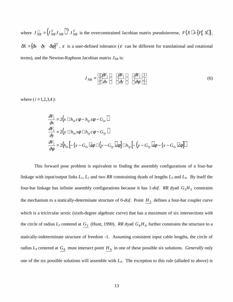
where ( ) TNRNR
TNRNR JJJJ
1−+ = is the overconstrained Jacobian matrix pseudoinverse, ( ) ( ){ }XFXF i= ,
{ }TyxX δφδδδ = , ε is a user-defined tolerance (ε can be different for translational and rotational
terms), and the Newton-Raphson Jacobian matrix JNR is:
=
∂φ∂
∂∂
∂∂ iii
NRF
y
F
x
FJ (6)
where ( 4,3,2,1=i ):
( )
( )
( ) ( )[ ] ( ) ( )[ ]( )φφφφ∂φ∂
φφ∂∂
φφ∂∂
cGxsGyhcGysGxhF
Gchshyy
F
Gshchxx
F
ixiyiyiyixixi
iyiyixi
ixiyixi
−−−−+−+−−=
−++=
−−+=
2
2
2
This forward pose problem is equivalent to finding the assembly configurations of a four-bar
linkage with input/output links L1, L2 and two RR constraining dyads of lengths L3 and L4. By itself the
four-bar linkage has infinite assembly configurations because it has 1-dof. RR dyad 33HG constrains
the mechanism to a statically-determinate structure of 0-dof. Point 3H defines a four-bar coupler curve
which is a tricircular sextic (sixth-degree algebraic curve) that has a maximum of six intersections with
the circle of radius L3 centered at 3G (Hunt, 1990). RR dyad 44HG further constrains the structure to a
statically-indeterminate structure of freedom -1. Assuming consistent input cable lengths, the circle of
radius L4 centered at 4G must intersect point 4H in one of these possible six solutions. Generally only
one of the six possible solutions will assemble with L4. The exception to this rule (alluded to above) is

14
that two possible valid solutions exist when the cable connections to ground iG lie on vertices of a
square and the hand-grip is a square. The same is true if the ground link and hand-grip are similar
rectangles. Therefore, hand-grip/ground link symmetry is not desirable as it causes uncertainty in the
forward pose solution.
3.2 Inverse Jacobian Matrix
The inverse rate kinematics problem for CSHIs is expressed by:
XML jj ��= (7)
where { }TnLLLL �����21= is the vector of cable rates, Mj is the n by 6 inverse Jacobian matrix
expressed with respect to {j} coordinates, and { } { }TzyxTj zyxvX ωωωω ���� == is the vector
of translational and rotational Cartesian rates, also in {j}. For the planar case, Mj is n by 3 and
{ }Tz
j yxX ω��� = . The inverse Jacobian matrix Mj with j=0 may be derived directly as follows
(Roberts et.al., 1997). First the ith cable rate is expressed and related to Cartesian variables using Eq. 3
(where leading superscripts were dropped for brevity):
( ) ( )[ ]( )[ ]iHiHi
i
iHT
iHiiHHi
iHTii
THiH
THiiHH
i
iiHHi
ii
ii
hRGxvLL
hRGxvGRhxL
RhGGxRhxGRhxdt
d
L
GRhxdt
d
LL
dt
d
LL
dt
dL
�
�
�
0
00
002202
202
1
1
2222
1
2
1
2
11
•−+•=
−+•−+=
−−+++=
−+=
==
(8)

15
Working on the rotational term, since iHiH RhhR 00 ×= ω� , we have:
( ) ( ) ( )( ) ( ) ( )iHiiiHiHiHiH
iHiHiHiHiHiH
RhLLRhRhGxRh
GxRhRhGxhRGx0000
000
×−•=ו=+−ו=
−ו=ו−=•−
ωωω
ωω�(9)
where we have used ( ) ( )acbcba ו=ו and ( )ababa +×=× . Now the relationship between one
cable rate and the Cartesian rates is:
( )[ ] ( )
×−=×−•+•=
ωω
vRhLLRhLvL
LL
TiHi
TiiHii
ii
00 ˆˆ1� (10)
where i
ii L
LL =ˆ is a unit vector in the Li direction. Therefore, the inverse Jacobian matrix is:
( )( )( )
×−
×−
×−
=
TnHn
Tn
TH
T
TH
T
RhLL
RhLL
RhLL
M
0
20
22
10
11
0
ˆˆ
ˆˆ
ˆˆ
��
(11)
This matrix is closely related to the Newton-Raphson Jacobian matrix (given for the planar case in Eq.
6): divide each row of JNR by 2Li to yield M0 ; care must be taken to convert Euler rotational rates to
Cartesian rotational rates for the spatial case. To apply Eq. 11 to the planar case, the translational z and
rotational x and y terms are dropped because they are zero, resulting in an n by 3 matrix M0 .
Kinematic singularities occur at CSHI configurations where the inverse Jacobian matrix M has
less than full rank. Singularities result when ( ) mMrank < where m is the dimension of Cartesian space.
In the neighborhood of kinematic singularities, the determinant MM T approaches zero. In a serial-

16
chain robotic arm, kinematic singularities physically correspond to configurations where the robot loses
one or more degrees-of-freedom. For in-parallel-actuated devices such as the Fig. 9 concept, kinematic
singularities physically correspond to configurations where the device gains additional, unwanted,
uncontrollable degrees-of-freedom.
For planar CSHIs, when the ground link and hand-grip are both squares (or similar rectangles)
and 0=φ , all configurations are kinematically singular, regardless of translations x, y. For cases where
the ground link and hand-grip are not similar geometric shapes, the only singular configurations are
when the hand-grip center is placed at 4,3,2,1; =iGi with $90±=φ , which is out of the workspace. The
minimum MM T is always greater than zero for non-similar geometric shapes, so there are no
singularities in practical operation. Thus, hand-grip/ground link symmetry is not desirable in terms of
singularities (this symmetry is also undesirable in the forward pose solution).
3.3 Statics Modeling
This section presents statics modeling for CSHIs. For static equilibrium the sum of external
forces and moments exerted on the hand-grip must equal the external wrench exerted on the human.
Figure 12 shows the static free-body diagram for the second cable; the remaining seven cables also have
tensions Fi (not shown for clarity).
The statics equations are:
RCGH
H
n
ii
R
n
ii
MgmPRM
FgmF
=×+
=+
∑
∑
=
=
0
1
1 (12)
17
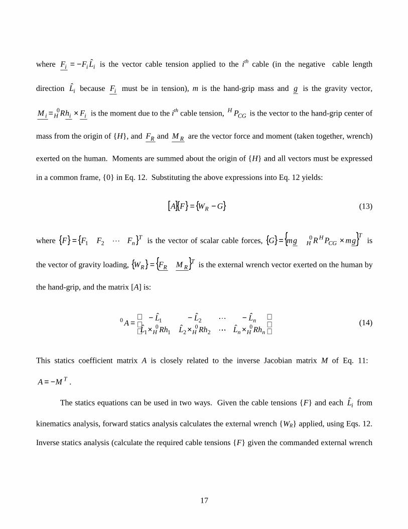
where iii LFF ˆ−= is the vector cable tension applied to the ith cable (in the negative cable length
direction iL̂ because iF must be in tension), m is the hand-grip mass and g is the gravity vector,
iiHi FhRM ×= 0 is the moment due to the ith cable tension, CGH P is the vector to the hand-grip center of
mass from the origin of {H}, and RF and RM are the vector force and moment (taken together, wrench)
exerted on the human. Moments are summed about the origin of {H} and all vectors must be expressed
in a common frame, {0} in Eq. 12. Substituting the above expressions into Eq. 12 yields:
[ ]{ } { }GWFA R −= (13)
where { } { }TnFFFF �21= is the vector of scalar cable forces, { } { }TCG
HH gmPRgmG ×= 0 is
the vector of gravity loading, { } { }TRRR MFW = is the external wrench vector exerted on the human by
the hand-grip, and the matrix [A] is:
×××−−−
=nHnHH
n
RhLRhLRhL
LLLA 0
20
210
1
210
ˆˆˆ
ˆˆˆ
�
�(14)
This statics coefficient matrix A is closely related to the inverse Jacobian matrix M of Eq. 11:
TMA −= .
The statics equations can be used in two ways. Given the cable tensions {F} and each iL̂ from
kinematics analysis, forward statics analysis calculates the external wrench {WR} applied, using Eqs. 12.
Inverse statics analysis (calculate the required cable tensions {F} given the commanded external wrench

18
{ WR} and each iL̂ ) is required for tension optimization control so the human can feel {WR} at the hand-
grip. This is presented in Section 4.
Figure 12. Static Diagram for Second Cable
3.4 Cable Interference
The mathematical transformations derived above (forward pose kinematics, inverse Jacobian
matrix, statics analysis) assume no cable interference during operation. This is a reasonable assumption
when the human inputs do not vary significantly from the equal-cable-length nominal configuration.
This would be useful for rate inputs to the virtual world, but position inputs would cause a problem and
require extensive re-indexing of the nominal position.
Therefore, for robustness, the kinematics and statics transformations must be updated to include
the possibility of cable interference. If the cables are sheathed in a low-friction material, cable
interference should present no troubles while extending the useful interface workspace. Modeling for
the interference case is a subject for future developments.
PHCG
M R F R
F 2
G 2
{H}
mg
h 2
19
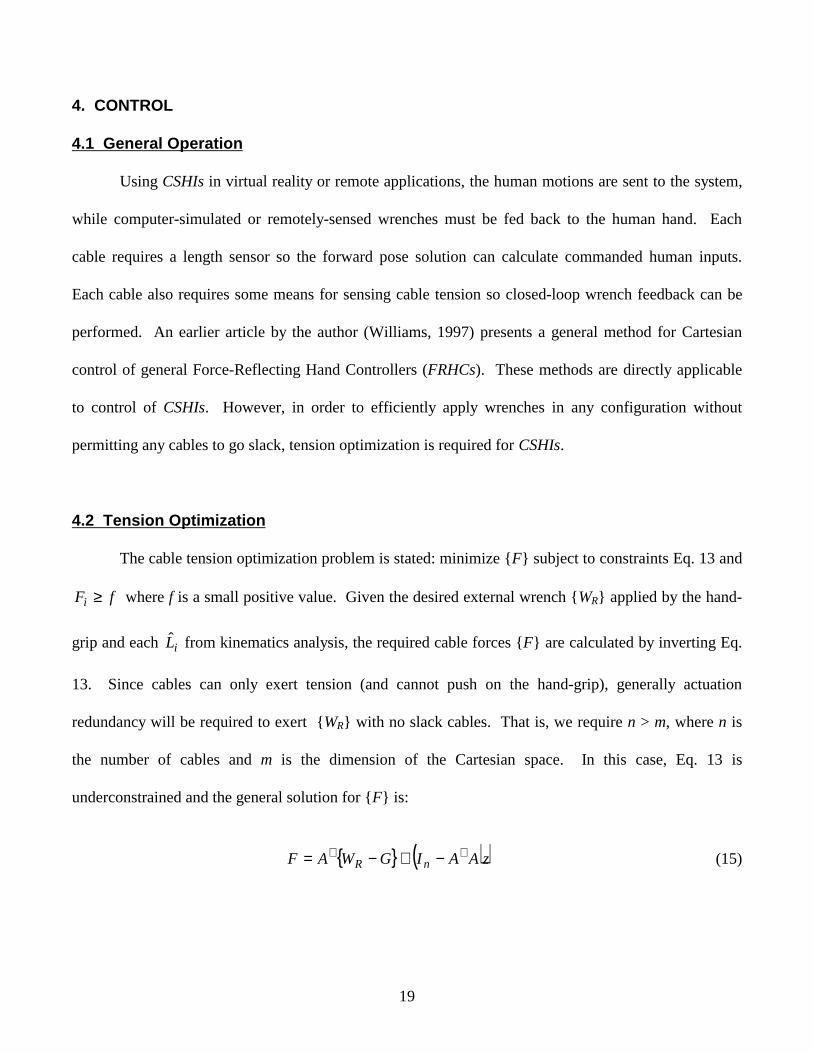
4. CONTROL
4.1 General Operation
Using CSHIs in virtual reality or remote applications, the human motions are sent to the system,
while computer-simulated or remotely-sensed wrenches must be fed back to the human hand. Each
cable requires a length sensor so the forward pose solution can calculate commanded human inputs.
Each cable also requires some means for sensing cable tension so closed-loop wrench feedback can be
performed. An earlier article by the author (Williams, 1997) presents a general method for Cartesian
control of general Force-Reflecting Hand Controllers (FRHCs). These methods are directly applicable
to control of CSHIs. However, in order to efficiently apply wrenches in any configuration without
permitting any cables to go slack, tension optimization is required for CSHIs.
4.2 Tension Optimization
The cable tension optimization problem is stated: minimize {F} subject to constraints Eq. 13 and
fFi ≥ where f is a small positive value. Given the desired external wrench {WR} applied by the hand-
grip and each iL̂ from kinematics analysis, the required cable forces {F} are calculated by inverting Eq.
13. Since cables can only exert tension (and cannot push on the hand-grip), generally actuation
redundancy will be required to exert {WR} with no slack cables. That is, we require n > m, where n is
the number of cables and m is the dimension of the Cartesian space. In this case, Eq. 13 is
underconstrained and the general solution for {F} is:
{ } ( )zAAIGWAF nR++ −+−= (15)

20
where In is the identity matrix of order n, z is an arbitrary vector, and ( ) 1−+ = TT AAAA is the
underconstrained Moore-Penrose pseudoinverse. The first term of Eq. 15 is the particular solution to
achieve the desired wrench, and the second term is the homogeneous solution which maps z to the null
space of A. An equivalent expression for Eq. 15 is:
{ } ∑−
=
+ +−=mn
jjjR NaGWAF
1
(16)
where the homogeneous solution is expressed as the sum of n-m independent null vectors Nj of A,
multiplied by arbitrary scalars aj.
To ensure all cables remain in tension in a given configuration while applying the commanded
wrench {WR}, aj mnj −= ,,1� (alternatively, z) must be chosen to yield F with strictly positive
components. To ascertain the existence of a feasible cable tension vector F, Eq. 13 is rewritten as:
0=FA (17)
where [ ]RWGAA −= and { }TFF 1= . F must be in the left null space of A in order to satisfy
Eq. 17. An algorithm for ascertaining the existence of a feasible solution to Eq. 17 (or Eq. 13) is given
in Roberts et.al. (1997). That work was motivated by the Charlotte application at NASA KSC. Roberts’
method is summarized below.
Static equilibrium is possible at a given configuration if and only if a left null vector of A
exists with all components non-negative and last component non-zero.

21
The ith cable tension is given by the ratio of the ith and last component of a non-negative left null
vector of A satisfying the above statement. Any zero components correspond to slack cables. If the last
component of every null vector is zero, the last column of A is not in the column space of A so the
hand-grip cannot achieve static equilibrium in that configuration even if the cables could push. Not all
CSHI configurations can exert any desired external wrench. The author and his students are currently
researching the wrench-exerting limitations for general CSHIs.

22
5. VR APPLICATIONS
The cable-suspended haptic interface (CSHI) may be used as a spatial 6-dof input/output device
for general virtual reality (VR) applications. The CSHI is used for input when the user moves the hand-
grip to explore virtual environments. It is used for output when reflecting six-degree-of-freedom wrench
feedback to the operator’s hand from the virtual environment. The potential areas for haptic
implementation in VR in the research, education, and commercial sectors is very broad, including
computer-generated scientific visualization, flight simulations and actual flight missions, virtual training,
virtual collaborative environments, rapid prototyping and virtual manufacturing, telerobotics, biomedical
visualization, surgical training, remote surgery, education, and entertainment. Haptics adds a major
dimension (force/moment and tactile information) missing in many current VR implementations
focusing on graphics and audio feedback. Inclusion of the haptic sensory feedback mode can greatly
improve telepresence quality.
One exciting area for future development with CSHIs is wrench/tactile fusion. That is, different
tactile feedback elements can be included at the hand-grip to provide simultaneous force/moment and
tactile feedback. Some early work has been accomplished in this area (e.g. Kontarinis and Howe, 1995;
Chen and Marcus, 1994), but it tends to focus on one-degree-of-freedom force feedback and a specific
tactile element. The bulk of the haptics research and development work to date focuses on either wrench
or tactile feedback. Wrench/tactile fusion is a rich area for future VR haptic feedback research involving
both mechanical/computer developers and human factors researchers. The CSHI will be a tool in this
pursuit.

23
6. CONCLUSION
A cable-suspended haptic interface (CSHI) concept was presented. Though the focus was
wrench reflection, future plans include wrench/tactile feedback fusion using the same device. The
forward pose solution, Jacobian matrix, statics equations, and tension optimization algorithm were
discussed. Cartesian control methods in an earlier article by the author may be implemented for control
of general CSHIs in virtual reality and remote operations. A planar CSHI prototype with four cables has
been completed and a spatial CSHI prototype with eight cables is under development.
7. ACKNOWLEDGEMENTS
This research was supported in part by an Air Force grant and the AFOSR Summer Faculty
Research Program. The author acknowledges researchers in the Human Sensory Feedback Lab at
Wright-Patterson AFB for support and facilities.

24
REFERENCES
J.S. Albus, R. Bostelman, and N.G. Dagalakis, 1993, “The NIST ROBOCRANE”, Journal of
Robotic Systems, 10(5): 709-724.
P.D. Campbell, P.L. Swaim, and C.J. Thompson, 1995, "Charlotte Robot Technology for Space
and Terrestrial Applications", 25th International Conference on Environmental Systems, San Diego,
SAE Paper 951520.
E.Y. Chen and B.A. Marcus, 1994, “EXOS Slip Display Research and Development”, ASME
International Mech Engr Congress, Chicago, IL, DSC 55(1): 265-270.
J.J. Craig, 1989, Introduction to Robotics: Mechanics and Control, Addison Wesley Publishing
Co., Reading, MA.
K.H. Hunt, 1990, Kinematic Geometry of Mechanisms, Clarendon Press, Oxford.
M. Ishii and M. Sato, 1994, “A 3D Spatial Interface Device Using Tensed Strings”, Presence-
Teleoperators and Virtual Environments, MIT Press, Cambridge, MA, 3(1): 81-86.
D. Kontarinis and R. Howe, 1995, “Tactile Display of Vibratory Information in Teleoperation
and Virtual Environments”, Presence-Teleoperators and Virtual Environments, MIT Press, Cambridge,
MA, 4(4): 387-402.
R. Lindemann and D. Tesar, 1989, “Construction and Demonstration of a 9-String 6-DOF Force
Reflecting Joystick for Telerobotics”, NASA International Conference on Space Telerobotics, (4): 55-63.
H.H. Mabie and C.F. Reinholtz, 1987, Mechanisms and Dynamics of Machinery, Wiley, NY.
T.H. Massie and K.J. Salisbury, 1994, “PHANToM Haptic Interface: A Device for Probing
Virtual Objects”, ASME International Mech Engr Congress, Chicago, IL, DSC 55(1): 295-299.
P. Nanua, K.J. Waldron, and V. Murthy, 1990, "Direct Kinematic Solution of a Stewart
Platform", IEEE Transactions on Robotic and Automation, 6(4): 438-443.
R.G. Roberts, T. Graham, and J.M. Trumpower, 1997, "On the Inverse Kinematics and Statics of
Cable-Suspended Robots", IEEE International Conf. on Systems, Man, and Cybernetics, Orlando, FL.
D. Stewart, 1966, "A Platform with Six Degrees of Freedom", Proceedings of the Institute of
Mechanical Engineers (London), 180(15): 371-386.
R.L. Williams II, 1997, "Control of Kinesthetic Haptic Interfaces in VR Applications",
International Journal of Virtual Reality, 3(1): 18-26.